improving design and operating parameters of the
TRANSCRIPT

1
IMPROVING DESIGN AND OPERATING PARAMETERS OF THE RECUPERATOR FOR
WASTE HEAT RECOVERY FROM ROTARY KILNS
Nenad P. STOJIĆ1, Rade M. KARAMARKOVIĆ
1*, Miodrag V. KARAMARKOVIĆ
2, Miloš V.
NIKOLIĆ1
*1 Faculty of Mechanical and Civil Engineering in Kraljevo, University of Kragujevac, Serbia
2Siemens AG Austria, Power and Gas, Vienna, Austria
* Corresponding author; E-mail: [email protected]
Depending on their applications, heat losses from the shells of rotary kilns
account for 3 to 25% of the total heat input. Over the hottest zone of the kiln
shell, an annular duct with a variable diameter is formed. Two air streams
entering the annulus at both ends flow to a common extraction point to
receive the thermal power equal to the ambient heat loss of the bare kiln.
The design does not require airtightness, utilizes the entire heat loss, and by
the variation of the airflow can be used over the kilns with variable
operating parameters (±20% heat loss), which show similar surface
temperature patterns. The main disadvantage of the design is the
approaching of the surfaces of the kiln and the recuperator at the outlet of
preheated air. This means that for a given heat loss and a surface
temperature pattern, the rotational eccentricity of the kiln shell is the most
influencing parameter that defines the air preheating temperature and the
efficiency of the recuperator. To solve the problem, 4 redesigns with: (i)
double annuluses, (ii) the usage of radiation fins, (iii) air addition, and (iv) a
combination of two basic designs are analyzed by the use of analytical and
CFD models. From the listed redesigns: (i) could be used only to prevent
overheating, (ii) has a modest positive effect, (iii) should be applied in
combination with (iv).
Key words: recuperator, design, model, CFD, rotary kiln, energy efficiency,
heat transfer, heat exchanger
1. Introduction
Rotary kilns are pyroprocessing devices used to raise materials to a high temperature in a
continuous process [1]. The kilns are widely applied in various technological processes such as [2]:
cement production, calcination, incineration, aluminum production, activated carbon manufacturing,
pyrolysis, food production, etc. The fact that the world cement and clinker production has increased
more than 240% during the first 20 years of the 21st century [3,4], testifies the importance of these
devices. In high-temperature applications of rotary kilns, heat loss from the shell to the environment
plays an important role. In the cement industry, it accounts for 8-15% [5], in dead burning of
magnesite 24.8% [6], in the calcination of dolomite 17.17% [1], of the total heat input. The heat loss is
not uniform along with rotary kilns and depends on their application, i.e., the processes that take place

2
inside, the thermal resistance and condition of coating and refractory layers inside them, and to a lesser
extent on the environmental conditions. The problem of coating and its assessment is addressed in Ref.
[7]. Several sections differ on a rotary kiln depending on temperature distribution and technological
process. The best option from the standpoint of the second law of thermodynamics is to insulate the
kiln and minimize the heat loss. In some of the above-mentioned applications, high-temperature
processes can cause overheating and endanger kiln shells. Because of that, the authors in Ref. [8, 9],
planned observation windows on the secondary insulating shell, whereas other authors have managed
to use the loss for:
(i) Electricity generation as an array of thermoelectric generation (TEG) units arranged on a secondary
shell coaxial with a rotary kiln [10, 11]. The temperature gradient between the two ends of the TEG
modules results in the generation of electricity as a result of the Seebeck effect. The layer of TEG
modules also acts as thermal insulation, because thermo-electric materials usually have low thermal
conductivity [10].
(ii) Water heating. Caputo et al. [5], developed and optimized the design of a recuperator for water
heating that utilizes the radiant heat loss from the shell of a rotary kiln. The utilized heat is used in
a district heating system. Another water heater, which is used as a heat source for absorption water
chiller is presented in Ref. [12]. It also uses only the radiant component of the heat loss. Through
experimental investigations and numerical simulations, Yin et al. [13–15], presented and optimized
a water heater that uses heat loss from a rotary kiln in a cement factory. In [13], the authors
experimentally investigated three different variants of the developed exchanger, which consists of a
radiant type exchanger in a hexagonal shell that uses radiant heat loss and one or two layers of
coiled pipes that use convective component of the heat loss. In the design, air flows vertically
between the kiln and the exchanger due to the diameter of 4060 mm.
In contrast to the presented systems, a recuperator that uses heat loss from the shell of a rotary
kiln for combustion air preheating was presented in Ref. [1]. Above the hottest zone of the kiln, where
the highest temperatures of the shell are located, an annular duct with a variable diameter is formed.
Two air streams entering the annulus at both ends flow to a common extraction point by the use of a
fan. The annulus is dimensioned so that the air receives a heat flow rate equal to the heat loss from the
bear kiln. fig. 1 a) illustrates the solution. The design does not require airtightness and utilizes the
entire heat loss: radiant and convective.
Fig. 1 b) shows the side view from the recuperator drawing. The design consists of two
symmetrical covers (1) that move on the horizontal rails (2). A constant force of the hydraulic
cylinders (3) connects the covers (1). In the case of a need or urgency, unloading of the hydraulic
cylinders (3) separates the covers (1). The weights (4) detach the recuperator. The inner of the covers
(1) are semicylindrical metal surfaces (5) with a predetermined radius that touch each other in two
lines of contact (6). Two rows of screws (7) regulate the airtightness and the distance between the
semicylindrical surfaces (5). The assembly of the covers (1) and the kiln (8) forms an annular gap for
airflow. The contact lines of the semicylindrical surfaces (5) are filled with a sealing material. Mineral
wool protected with an aluminum sheet (9) prevents heat loss from the surfaces (5). The fan (10)
extracts airflow over the hottest zone of the kiln by the use of two flexible ducts (11). The recuperator
uses radial blinds at both ends to control airflows. A modification of the presented principle with an
extra annulus filled with a phase-change material was experimentally investigated in [16].

3
The design shown in Fig. 1 is simple, cost-effective, uses the entire heat loss, prevents
overheating, and does not influence the technological process within the kiln. Nevertheless, some
conditions disfavor its usage. Because of its compressibility, the air is not an economical heat carrier at
distances longer than a few tens of meters. However, the main disadvantage of the design is the
approach of the kiln and recuperator surfaces at the outlet of preheated air (see fig. 1 a)). This happens
at the air exit from the annulus, where the temperature difference between the air and the kiln is the
smallest. The air needs higher heat transfer coefficients and therefore higher velocities to receive the
precise amount of heat with a given surface area. This could be an insurmountable problem for the
kilns with large rotational eccentricities. Ref. [17], demonstrates the significance of the problem, and
in that respect, the position of the recuperator relative to the supporting roller bearing is important.
Regarding the defined problem, the goals of the paper are: (i) to analyze the performance of the
recuperator shown in Fig. 1 depending on the rotational eccentricity, to examine its behavior in an
unsteady operation, and to find the design parameters that will increase the distance between the kiln
and the recuperator; (ii) to present and analyze redesigns so as the air is preheated to the highest
possible temperature. The simplest way to solve the defined problem is to increase the airflow.
However, this approach decreases the exergy efficiency of the recuperator because of a lower
preheating temperature and requires finding the use of preheated air other than for combustion. One
way to find the optimal usage of preheated air is to employ the pinch analysis as in Ref. [18].
Figure 1. a) The concept of the annular recuperator together with the mass balance of the
examined kiln. b) Side drawing of the recuperator [1]
1.1. Proposed redesigns and improved operating parameters
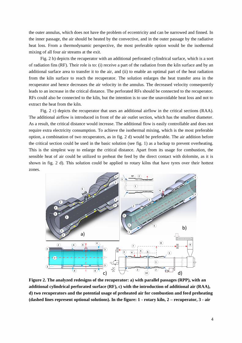
Fig. 2 shows 3 redesigns used to achieve the second goal. Fig. 2 a) depicts the recuperator with
parallel passages (RPP). RPP intends to: (i) decrease air velocity in the inner annulus and consequently
increase the distance between the kiln and the recuperator, and (ii) promote heat transfer to the air in
4
the outer annulus, which does not have the problem of eccentricity and can be narrowed and finned. In
the inner passage, the air should be heated by the convective, and in the outer passage by the radiative
heat loss. From a thermodynamic perspective, the most preferable option would be the isothermal
mixing of all four air streams at the exit.
Fig. 2 b) depicts the recuperator with an additional perforated cylindrical surface, which is a sort
of radiation fins (RF). Their role is to: (i) receive a part of the radiation from the kiln surface and by an
additional surface area to transfer it to the air, and (ii) to enable an optimal part of the heat radiation
from the kiln surface to reach the recuperator. The solution enlarges the heat transfer area in the
recuperator and hence decreases the air velocity in the annulus. The decreased velocity consequently
leads to an increase in the critical distance. The perforated RFs should be connected to the recuperator.
RFs could also be connected to the kiln, but the intention is to use the unavoidable heat loss and not to
extract the heat from the kiln.
Fig. 2 c) depicts the recuperator that uses an additional airflow in the critical sections (RAA).
The additional airflow is introduced in front of the air outlet section, which has the smallest diameter.
As a result, the critical distance would increase. The additional flow is easily controllable and does not
require extra electricity consumption. To achieve the isothermal mixing, which is the most preferable
option, a combination of two recuperators, as in fig. 2 d) would be preferable. The air addition before
the critical section could be used in the basic solution (see fig. 1) as a backup to prevent overheating.
This is the simplest way to enlarge the critical distance. Apart from its usage for combustion, the
sensible heat of air could be utilized to preheat the feed by the direct contact with dolomite, as it is
shown in fig. 2 d). This solution could be applied to rotary kilns that have tyres over their hottest
zones.
Figure 2. The analyzed redesigns of the recuperator: a) with parallel passages (RPP), with an
additional cylindrical perforated surface (RF), c) with the introduction of additional air (RAA),
d) two recuperators and the potential usage of preheated air for combustion and feed preheating
(dashed lines represent optional solutions). In the figure: 1 - rotary kiln, 2 – recuperator, 3 - air
1
2
3
3
3
3
3
3
3
3
6
а)
1
2
5
5
3
3
3
3
6
b)
3
1
2
c)
1
2
3 3
33
44
4 4
6
d)
3 6
1
2
78
2
344
10
9
5
flow, 4 - additional air, 5 – cylindrical fins, 6 – exit of the preheated air, 7 – combustion air, 8 –
air used to preheat the feed, 9 – heat recovery to solids, 10 – rotary kiln tyre ring
Behind the defined goals, the motive for the paper was the implementation of the basic solution
on rotary kilns with large rotational eccentricities, varying operating conditions, and tyres over their
warmest zones. These redesigns have not been implemented in practice, and their implementation by
the use of cell and CFD modeling methods is analyzed in the paper.
2. Case study of the heat loss from the shell of a rotary kiln
Fig. 1 schematically shows the mass balance of a rotary kiln, over which the recuperator and its
modifications are examined. The main features of the kiln are: length 80 m, outer diameter 2 m,
rotational speed 0.75÷0.95 rpm, inclination 3%, maximum output 135 tons/day of calcine (CaO∙MgO),
heavy fuel oil consumption 948.3 l/h at the maximum output [1]. The inclination and rotational speed
enable counterflows of the exhaust gases and dolomite (CaCO3∙MgCO3) inside the kiln [1].
The heat loss of the kiln shell was determined by the heat balance [1]. The loss was analytically
verified in [1], by dividing the shell into 24 sections. The dissection was made according to the
approximately equal surface temperatures. The total heat loss is:
∑
∑
∑
∑ (
)
(1)
As the kiln is sheltered from the wind, the convective heat losses for all i sections were
calculated by the model for free convection around a horizontal cylinder [19], (taken from [20]). In
each section i, the radiation heat loss were calculated for the case of a pipe within a big room
[21]. The model showed a good correlation with the energy balance (see [1]) and was additionally
used in the paper: (1) in the case when enriched air is used for fuel combustion in the kiln to determine
the heat loss based on the measured surface temperatures, and (2) to determine surface temperatures
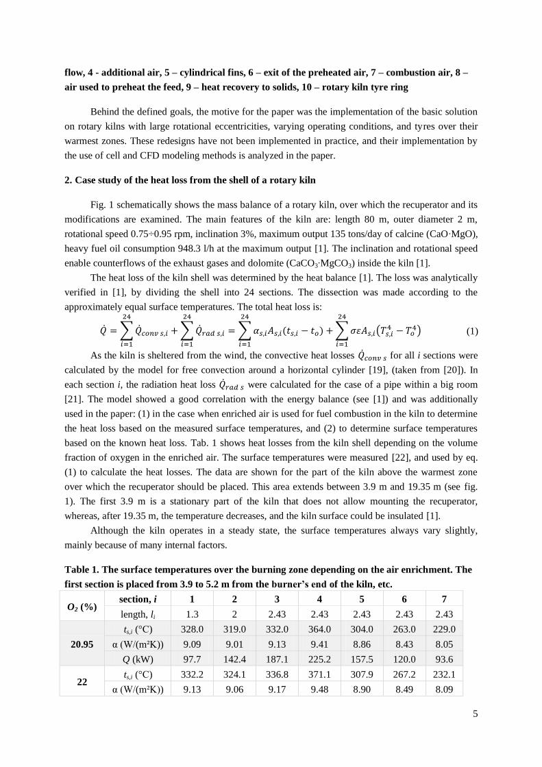
based on the known heat loss. Tab. 1 shows heat losses from the kiln shell depending on the volume
fraction of oxygen in the enriched air. The surface temperatures were measured [22], and used by eq.
(1) to calculate the heat losses. The data are shown for the part of the kiln above the warmest zone
over which the recuperator should be placed. This area extends between 3.9 m and 19.35 m (see fig.
1). The first 3.9 m is a stationary part of the kiln that does not allow mounting the recuperator,
whereas, after 19.35 m, the temperature decreases, and the kiln surface could be insulated [1].
Although the kiln operates in a steady state, the surface temperatures always vary slightly,
mainly because of many internal factors.
Table 1. The surface temperatures over the burning zone depending on the air enrichment. The
first section is placed from 3.9 to 5.2 m from the burner’s end of the kiln, etc.
O2 (%) section, i 1 2 3 4 5 6 7
length, li 1.3 2 2.43 2.43 2.43 2.43 2.43
20.95
ts,i (°C) 328.0 319.0 332.0 364.0 304.0 263.0 229.0
α (W/(m²K)) 9.09 9.01 9.13 9.41 8.86 8.43 8.05
Q (kW) 97.7 142.4 187.1 225.2 157.5 120.0 93.6
22 ts,i (°C) 332.2 324.1 336.8 371.1 307.9 267.2 232.1
α (W/(m²K)) 9.13 9.06 9.17 9.48 8.90 8.49 8.09
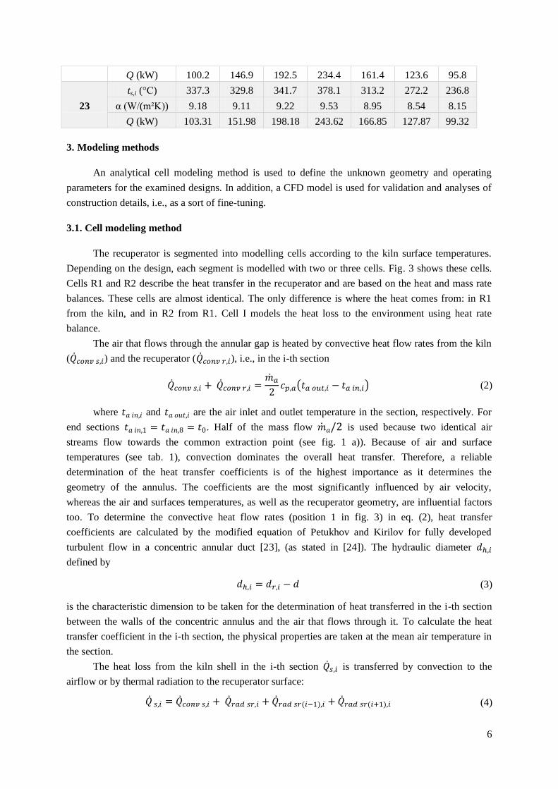
6
Q (kW) 100.2 146.9 192.5 234.4 161.4 123.6 95.8
23
ts,i (°C) 337.3 329.8 341.7 378.1 313.2 272.2 236.8
α (W/(m²K)) 9.18 9.11 9.22 9.53 8.95 8.54 8.15
Q (kW) 103.31 151.98 198.18 243.62 166.85 127.87 99.32
3. Modeling methods
An analytical cell modeling method is used to define the unknown geometry and operating
parameters for the examined designs. In addition, a CFD model is used for validation and analyses of
construction details, i.e., as a sort of fine-tuning.
3.1. Cell modeling method
The recuperator is segmented into modelling cells according to the kiln surface temperatures.
Depending on the design, each segment is modelled with two or three cells. Fig. 3 shows these cells.
Cells R1 and R2 describe the heat transfer in the recuperator and are based on the heat and mass rate
balances. These cells are almost identical. The only difference is where the heat comes from: in R1
from the kiln, and in R2 from R1. Cell I models the heat loss to the environment using heat rate
balance.
The air that flows through the annular gap is heated by convective heat flow rates from the kiln
( ) and the recuperator ( ), i.e., in the i-th section
( ) (2)
where and are the air inlet and outlet temperature in the section, respectively. For
end sections . Half of the mass flow is used because two identical air
streams flow towards the common extraction point (see fig. 1 a)). Because of air and surface
temperatures (see tab. 1), convection dominates the overall heat transfer. Therefore, a reliable
determination of the heat transfer coefficients is of the highest importance as it determines the
geometry of the annulus. The coefficients are the most significantly influenced by air velocity,
whereas the air and surfaces temperatures, as well as the recuperator geometry, are influential factors
too. To determine the convective heat flow rates (position 1 in fig. 3) in eq. (2), heat transfer
coefficients are calculated by the modified equation of Petukhov and Kirilov for fully developed
turbulent flow in a concentric annular duct [23], (as stated in [24]). The hydraulic diameter
defined by
(3)
is the characteristic dimension to be taken for the determination of heat transferred in the i-th section
between the walls of the concentric annulus and the air that flows through it. To calculate the heat
transfer coefficient in the i-th section, the physical properties are taken at the mean air temperature in
the section.
The heat loss from the kiln shell in the i-th section is transferred by convection to the
airflow or by thermal radiation to the recuperator surface:
(4)

7
The last three terms on the right-hand side of eq. (4) designate thermal radiation of the kiln surface
towards the recuperator in the i-th section , and two adjacent sections: upstream
and downstream . The radiation heat transfer rate between the surfaces of the kiln and the
recuperator in the i-th section is [25]:
(
)
(
) (5)
where the view factor F12≈1 is obtained by the graphical method [26]:
(6)
As F12≈1, eq. (5) is similar to the equation for infinitely long concentric pipes.
The third (eq. (2), (4), and (7)) balance is the heat rate balance for the recuperator surface:
(7)
Three thermal radiation heat gains (left-hand side of eq. (7)) are transferred by convection to the air
and towards the second passage (see fig. 3 a)) or the surroundings (see fig. 1 and 2) .
When insulation thickness is known, is calculated, otherwise, it is estimated. The convection term
in eq. (7) is calculated in the same manner as for the kiln surface. In eq. (4) and (7), the terms
that determine thermal radiation between the segment and the adjacent segments can be neglected
because of: (i) small view factors (less than 0.01) given by
(8)
(ii) similar surface temperatures that almost cancel out radiation heat transfer rates between the
adjacent sections (see tab. 1), and (iii) not fully opened the end sections towards the environment
because of the use of radial blinds for airflow control. Through the validation of the model for the
basic design (see fig.1) in Ref. [1], the previous simplification was also validated.
The heat loss rate of the i-th section is transferred through a three-layer-cylindrical wall to the
outer surface, from which the heat is transferred into the environment by convection and radiation:
( ) (
) (9)
The thermal conductivities for steel pipe , mineral wool insulation , and aluminum sheet cover
are taken as in Ref. [27]. The heat transfer coefficient for natural convection from the outer surface
to the environment is taken from Ref. [20], and is identical to the heat loss from the bare kiln. The
radiation from the outer surface is taken for the case of a pipe within a big room. The emissivity of the
aluminum sheet is taken from [21].
3.2. Recuperator with radiation fins
RF recuperator (see fig. 2 b) and 3 b)) is modeled similarly to RPP. Neglecting thermal
radiation between the different sections as in eq. (7), the heat rate balances for the i-th section are:
( ) (10)
(11)
(12)

8
(13)
These equations are heat rate balances: eq. (10) for the airflow, eq. (11) for the kiln surface, eq. (12)
for the fin (see fig. 3 b), and eq. (13) for the recuperator surface. The fin is connected to the
recuperator. Compared with other surfaces involved in the heat transfer, the surface area of the
connection is small. Because of that, its role in heat transfer is neglected.
The convective heat transfer rates in eq. (10-13): at the kiln surface , at the surface of
the recuperator , and at the fin are calculated by the use of heat transfer coefficients
that are calculated according to Ref. [24] (cited by [23]). The Nusselt number eq. (14) is modified by
taking into account the effect of temperature-dependent property variations, eq. (15). For the Prandtl
number in the range 0.5≤Pr≤1.5, these equations are:
[ ] (14)
(
)
(15)
The hydraulic diameter in eq. (14) is calculated by eq. (3). In eq. (11-13) radiation heat transfer
rates are calculated by an electric circuit analogy for heat exchange among diffuse gray bodies [23]:
(
)
(
)
(16)
(
)
(
)
(17)
(
)
(
)
(18)
In eq. (16-18), the view factors are determined by two-dimensional graphical method [24], and f <1 is
the relative closedness of the fin surface in the i-th segment
f=1 - Afo,i/Af,I (19)
where Afo,i [m2] is the total area of the openings on a radiation fin in the i-th section, and Af,i [m
2] is the
total surface area of the radiation fin (see fig. 3 b)). The purpose of the openings is to allow a part of
radiation heat transfer to reach the recuperator surface. Fig. 3 b) shows radiative heat transfer
resistances for the examined recuperator.

9
Figure 3. a) Graphical illustration of the heat transfer and characteristic dimensions of the
annular recuperator, b) Radiation heat transfer resistances and the schematic of the RF
recuperator
In the presented models, the basic temperature-dependent thermodynamic properties for air
(density, thermal conductivity, thermal diffusivity, dynamic viscosity, Prandtl number, specific heat
capacity, and enthalpy) are calculated according to Ref. [28–30].
3.3. CFD model
To simulate the experimental setup and to indirectly validate the RF model as well as to
examine the design details commercially available software Ansys and its integration module Fluent
were used. In all simulations, the inlet/outlet pair: mass-flow-inlet/pressure outlet was used for the
boundary condition. For compressible fluids, this is the most stable and the most frequently used pair
of boundary conditions [31], defined by the mass flow rate and temperature of the fluid at the inlet,
and relative pressure of 0 Pa at the outlet. The applied model uses the energy equation, standard k-ε
turbulent model, and the surface-to-surface radiation model. To solve the model, the pressure-velocity
coupling method was used. It solved the model with the SIMPLEC scheme that used the heigh-order
relaxation option. The absolute convergence criterion is that the residual for energy and all other
quantities were less than 1 E-05 and 0.001, respectively. The set convergence criteria were met before
500 iterations.
3.4. Validation of the RF model
Although it is composed of reliable heat transfer submodels, the RF model was experimentally
validated. Fig. 4 shows the experimental setup, its picture, the average results, measuring errors,
instruments, and methods. The connection between a wood pellet boiler and a chimney is used for the
experiment. Compared with the real conditions, the surface temperature in the experiment was lower
and the innermost cylinder was not rotating. The velocity at the outer surface of the examined rotary
kiln is lower than 0.14 m/s because of low rotational speed (below 0.95 rpm). Compared with the air
velocities in the longitudinal direction (see tab. 3, 5, and 6), the velocity of the kiln is very low and its
influence on the convective heat transfer can be neglected. Additionally, the comparison of CFD and
cell models in the results section speaks in favor of the neglection. Although the surface temperature is
10
lower, the temperature differences between the surfaces and between air and the surfaces are of the
same magnitude as in real conditions.
To compare the results of the experiment and the models, and to evaluate the accuracy of the
experimental results, the uncertainty analysis is performed. The uncertainty R of a function F can be
described as [32] (cited by [13]):
√(
)
(
)
(
)
(20)
where x1, x2, …, xn are independent variables and W1, W2, …, Wn are regarded as their corresponding
uncertainties. The uncertainties are presented in tab. 2, except for the heat loss, which is given in fig.
4.
The RF cell could not be verified on its own by comparison with the experimental results.
Because of that, the RF cell was combined with a flue gas cell, which was developed and validated in
[27]. As this is a sort of indirect validation, the results are additionally checked with the simulation of
the experimental setup by the CFD model. For the CFD model, the mesh is composed of 1.161.350
nodes and 1.659.512 elements with the average quality of an element 0.301, and the average
orthogonal quality of 0.7814. These parameters are used to evaluate the relative quality of the mesh.
The quality is assessed by the number of elements and nodes that are quantitative indicators
concerning: the volume and the shape in which the mesh is generated, the mesh density near the walls
(borders) and at the cross-sections, the ratio between the height and length of an element, as well as
the shape of an element.
In the CFD model, densities of air and flue gas are taken as for an ideal gas, whereas the
specific heat capacity of the flue gas is calculated as for an ideal gas mixture. Fig. 5 shows the
simulation results for the CFD model depending on the position of the cross-section.
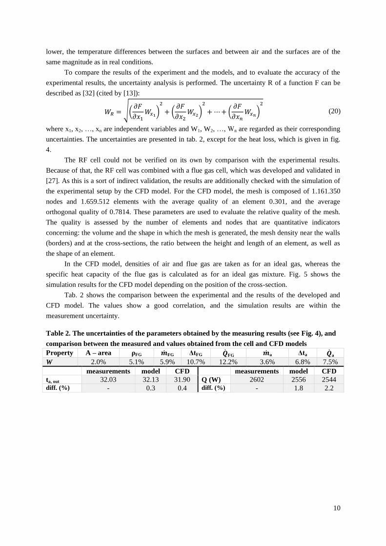
Tab. 2 shows the comparison between the experimental and the results of the developed and
CFD model. The values show a good correlation, and the simulation results are within the
measurement uncertainty.
Table 2. The uncertainties of the parameters obtained by the measuring results (see Fig. 4), and
comparison between the measured and values obtained from the cell and CFD models
Property A – area ρFG FG ΔtFG FG a Δta a
W 2.0% 5.1% 5.9% 10.7% 12.2% 3.6% 6.8% 7.5%
measurements model CFD measurements model CFD
ta, out 32.03 32.13 31.90 Q (W) 2602 2556 2544 diff. (%) - 0.3 0.4 diff. (%) - 1.8 2.2

11
Figure 4. a) Experimental setup and measuring details: results, errors, instruments, and
methods. b) picture of the experimental setup. 1 – flue gas pipe, 2 – radiation fin (f=0.5, i.e., 50%
of the radiation fins are hollow to enable radiative heat transfer from the kiln to the recuperator
surface (see position 2 and Fig. 3 b).), 3 – recuperator, 4 – flow control dampers
Figure 5. The simulation results of the CFD model for the experiment shown in Fig. 4. a) flue gas
temperature, b) air temperature. x/L –represents the relative distance from the entry (see Fig. 4)
CO2 – vol% - calc.O2 – vol%±0.8 vol%CO – 173ppm±5 vol%
CO2 – CO – H2O – N2 – O2–
dry gasmeasured values
wet gas composition calculated values
Testo 350 xl – O2, CO2, COH2O – measured by condensation and
absorption, CO2, N2 calculated according to the wood pellet composition
Measuring point 1 – flue gas
avg. temperature162.1±0.5%
volume flow rate0.289m3/s±3%
Chromel-Alumelthermocouple
measuring range 0-1000
Pitot – Prandtl tube volume flow rate
ISO 10780Zambelli COMBI S
Measuring point 2 -air avg. air inlet temperature
15.2±0.55 Testo 925-1
TC Type K (NiCr-Ni)
volume flow rate - air0.123m³/s±3%
Pitot – Prandtl tube – volume flow rate ISO 10780Zambelli COMBI S
Measuring point 3 heat loss to surroundings
42.6 W ±2.8% Heat flow meter
HFM 201 Kyoto Eletronics
Measuring point – flue gas
Thermocouple Chromel-Alumel
measuring range 0-1000
avg. temperature151.7±0.5%
a)
b)
Measuring point 4 -air avg. air outlet temperature
32.03±0.6 Testo 925-1 TC Type K (NiCr-Ni)
x/L = 1/3 x/L = 2/3 x/L = 1
x/L = 1/3 x/L = 2/3 x/L = 1
T = 19.11 [°C] T = 24.27 [°C] T = 31.90 [°C]
a)
b)
12
4. Results
The air preheated in the recuperator is extracted at the position placed so that both halves utilize
equal heat losses of the kiln. The division enables the isothermal mixing of two air streams that leave
the recuperator above the kiln section with the highest surface temperature (see fig. 1).
Thermodynamically, this is advantageous because the temperature difference between the air and the
kiln surface along the recuperator is analogous to that of counter-current heat exchangers (see tab. 1).
Because of the division of the 4th section in tab. 1, there are 8 instead of 7 sections in the following
analyses.
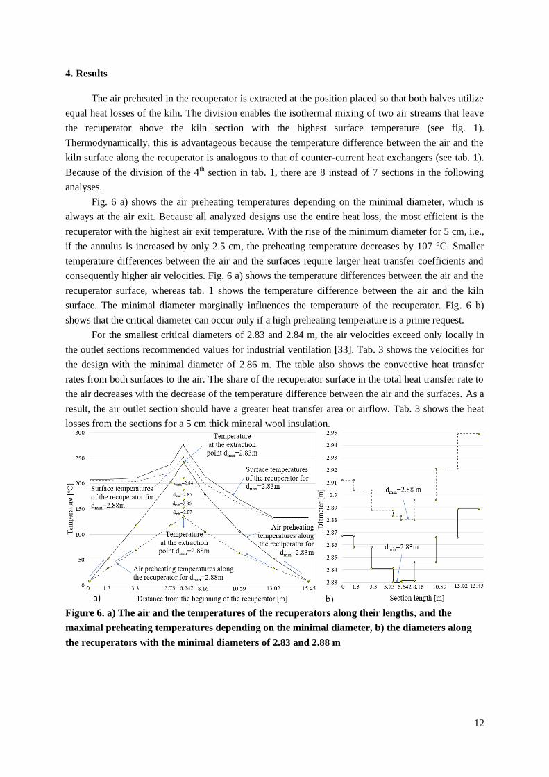
Fig. 6 a) shows the air preheating temperatures depending on the minimal diameter, which is
always at the air exit. Because all analyzed designs use the entire heat loss, the most efficient is the
recuperator with the highest air exit temperature. With the rise of the minimum diameter for 5 cm, i.e.,
if the annulus is increased by only 2.5 cm, the preheating temperature decreases by 107 °C. Smaller
temperature differences between the air and the surfaces require larger heat transfer coefficients and
consequently higher air velocities. Fig. 6 a) shows the temperature differences between the air and the
recuperator surface, whereas tab. 1 shows the temperature difference between the air and the kiln
surface. The minimal diameter marginally influences the temperature of the recuperator. Fig. 6 b)
shows that the critical diameter can occur only if a high preheating temperature is a prime request.
For the smallest critical diameters of 2.83 and 2.84 m, the air velocities exceed only locally in
the outlet sections recommended values for industrial ventilation [33]. Tab. 3 shows the velocities for
the design with the minimal diameter of 2.86 m. The table also shows the convective heat transfer
rates from both surfaces to the air. The share of the recuperator surface in the total heat transfer rate to
the air decreases with the decrease of the temperature difference between the air and the surfaces. As a
result, the air outlet section should have a greater heat transfer area or airflow. Tab. 3 shows the heat
losses from the sections for a 5 cm thick mineral wool insulation.
Figure 6. a) The air and the temperatures of the recuperators along their lengths, and the
maximal preheating temperatures depending on the minimal diameter, b) the diameters along
the recuperators with the minimal diameters of 2.83 and 2.88 m
13
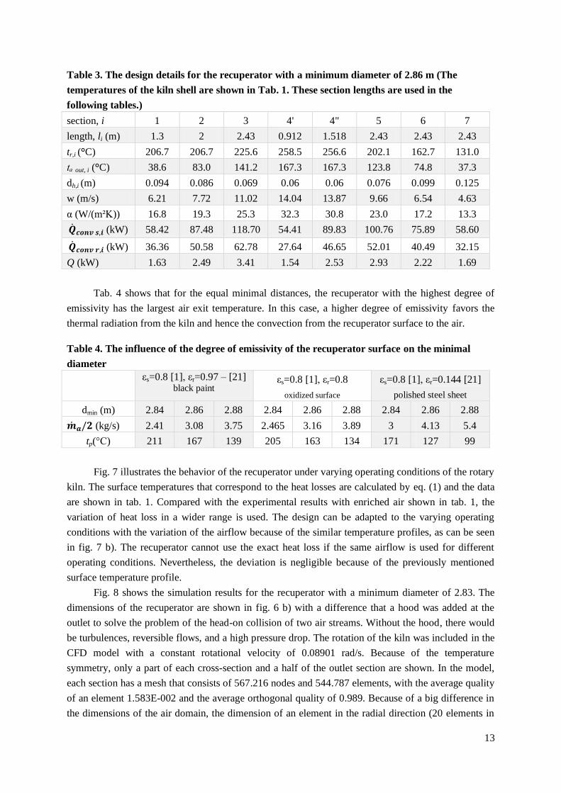
Table 3. The design details for the recuperator with a minimum diameter of 2.86 m (The
temperatures of the kiln shell are shown in Tab. 1. These section lengths are used in the
following tables.)
section, i 1 2 3 4' 4" 5 6 7
length, li (m) 1.3 2 2.43 0.912 1.518 2.43 2.43 2.43
tr,i (°C) 206.7 206.7 225.6 258.5 256.6 202.1 162.7 131.0
tₐ out, i (°C) 38.6 83.0 141.2 167.3 167.3 123.8 74.8 37.3
dh,i (m) 0.094 0.086 0.069 0.06 0.06 0.076 0.099 0.125
w (m/s) 6.21 7.72 11.02 14.04 13.87 9.66 6.54 4.63
α (W/(m²K)) 16.8 19.3 25.3 32.3 30.8 23.0 17.2 13.3
(kW) 58.42 87.48 118.70 54.41 89.83 100.76 75.89 58.60
(kW) 36.36 50.58 62.78 27.64 46.65 52.01 40.49 32.15
Q (kW) 1.63 2.49 3.41 1.54 2.53 2.93 2.22 1.69
Tab. 4 shows that for the equal minimal distances, the recuperator with the highest degree of
emissivity has the largest air exit temperature. In this case, a higher degree of emissivity favors the
thermal radiation from the kiln and hence the convection from the recuperator surface to the air.
Table 4. The influence of the degree of emissivity of the recuperator surface on the minimal
diameter
εs=0.8 [1], εr=0.97 – [21] black paint
εs=0.8 [1], εr=0.8
oxidized surface
εs=0.8 [1], εr=0.144 [21]
polished steel sheet
dmin (m) 2.84 2.86 2.88 2.84 2.86 2.88 2.84 2.86 2.88
(kg/s) 2.41 3.08 3.75 2.465 3.16 3.89 3 4.13 5.4
tp(°C) 211 167 139 205 163 134 171 127 99
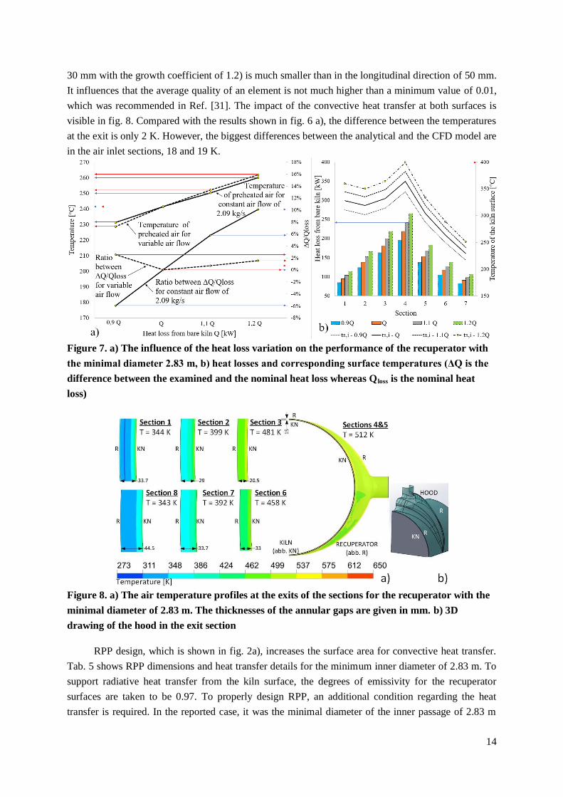
Fig. 7 illustrates the behavior of the recuperator under varying operating conditions of the rotary
kiln. The surface temperatures that correspond to the heat losses are calculated by eq. (1) and the data
are shown in tab. 1. Compared with the experimental results with enriched air shown in tab. 1, the
variation of heat loss in a wider range is used. The design can be adapted to the varying operating
conditions with the variation of the airflow because of the similar temperature profiles, as can be seen
in fig. 7 b). The recuperator cannot use the exact heat loss if the same airflow is used for different
operating conditions. Nevertheless, the deviation is negligible because of the previously mentioned
surface temperature profile.
Fig. 8 shows the simulation results for the recuperator with a minimum diameter of 2.83. The
dimensions of the recuperator are shown in fig. 6 b) with a difference that a hood was added at the
outlet to solve the problem of the head-on collision of two air streams. Without the hood, there would
be turbulences, reversible flows, and a high pressure drop. The rotation of the kiln was included in the
CFD model with a constant rotational velocity of 0.08901 rad/s. Because of the temperature
symmetry, only a part of each cross-section and a half of the outlet section are shown. In the model,
each section has a mesh that consists of 567.216 nodes and 544.787 elements, with the average quality
of an element 1.583E-002 and the average orthogonal quality of 0.989. Because of a big difference in
the dimensions of the air domain, the dimension of an element in the radial direction (20 elements in
14
30 mm with the growth coefficient of 1.2) is much smaller than in the longitudinal direction of 50 mm.
It influences that the average quality of an element is not much higher than a minimum value of 0.01,
which was recommended in Ref. [31]. The impact of the convective heat transfer at both surfaces is
visible in fig. 8. Compared with the results shown in fig. 6 a), the difference between the temperatures
at the exit is only 2 K. However, the biggest differences between the analytical and the CFD model are
in the air inlet sections, 18 and 19 K.
Figure 7. a) The influence of the heat loss variation on the performance of the recuperator with
the minimal diameter 2.83 m, b) heat losses and corresponding surface temperatures (ΔQ is the
difference between the examined and the nominal heat loss whereas Qloss is the nominal heat
loss)
Figure 8. a) The air temperature profiles at the exits of the sections for the recuperator with the
minimal diameter of 2.83 m. The thicknesses of the annular gaps are given in mm. b) 3D
drawing of the hood in the exit section
RPP design, which is shown in fig. 2a), increases the surface area for convective heat transfer.
Tab. 5 shows RPP dimensions and heat transfer details for the minimum inner diameter of 2.83 m. To
support radiative heat transfer from the kiln surface, the degrees of emissivity for the recuperator
surfaces are taken to be 0.97. To properly design RPP, an additional condition regarding the heat
transfer is required. In the reported case, it was the minimal diameter of the inner passage of 2.83 m
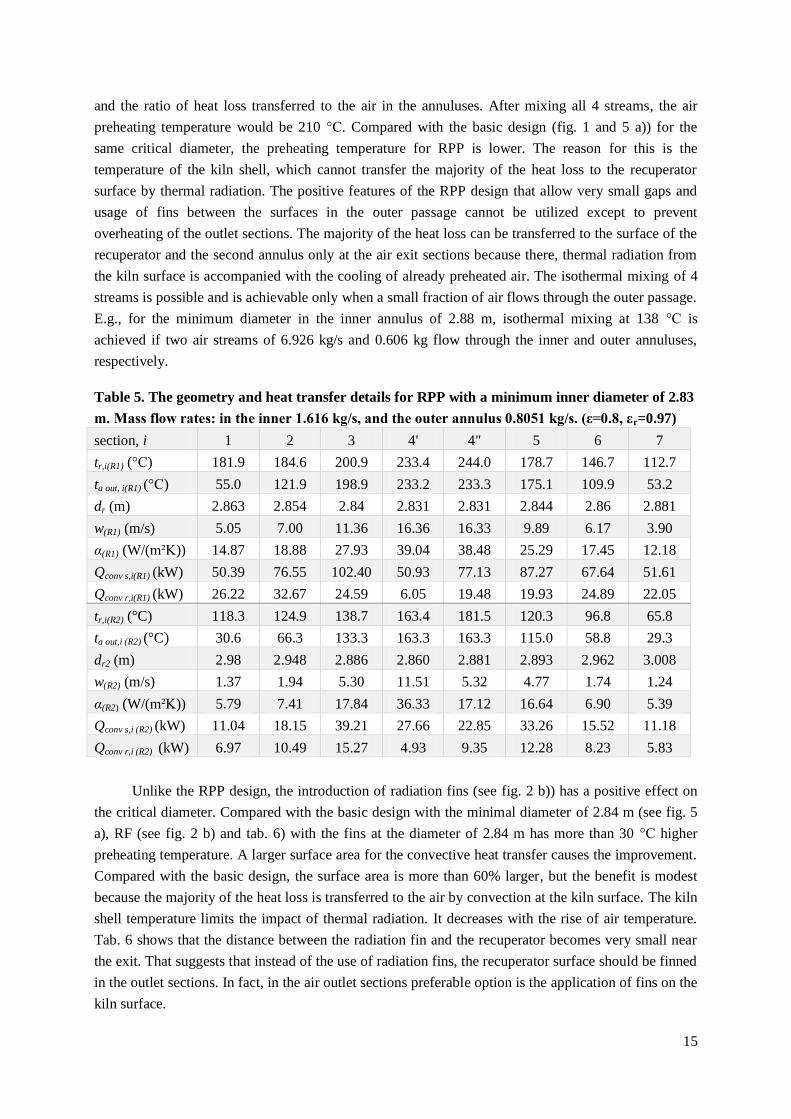
15
and the ratio of heat loss transferred to the air in the annuluses. After mixing all 4 streams, the air
preheating temperature would be 210 °C. Compared with the basic design (fig. 1 and 5 a)) for the
same critical diameter, the preheating temperature for RPP is lower. The reason for this is the
temperature of the kiln shell, which cannot transfer the majority of the heat loss to the recuperator
surface by thermal radiation. The positive features of the RPP design that allow very small gaps and
usage of fins between the surfaces in the outer passage cannot be utilized except to prevent
overheating of the outlet sections. The majority of the heat loss can be transferred to the surface of the
recuperator and the second annulus only at the air exit sections because there, thermal radiation from
the kiln surface is accompanied with the cooling of already preheated air. The isothermal mixing of 4
streams is possible and is achievable only when a small fraction of air flows through the outer passage.
E.g., for the minimum diameter in the inner annulus of 2.88 m, isothermal mixing at 138 °C is
achieved if two air streams of 6.926 kg/s and 0.606 kg flow through the inner and outer annuluses,
respectively.
Table 5. The geometry and heat transfer details for RPP with a minimum inner diameter of 2.83
m. Mass flow rates: in the inner 1.616 kg/s, and the outer annulus 0.8051 kg/s. (ε=0.8, εr=0.97)
section, i 1 2 3 4' 4" 5 6 7
tr,i(R1) (°C) 181.9 184.6 200.9 233.4 244.0 178.7 146.7 112.7
ta out, i(R1) (°C) 55.0 121.9 198.9 233.2 233.3 175.1 109.9 53.2
dr (m) 2.863 2.854 2.84 2.831 2.831 2.844 2.86 2.881
w(R1) (m/s) 5.05 7.00 11.36 16.36 16.33 9.89 6.17 3.90
α(R1) (W/(m²K)) 14.87 18.88 27.93 39.04 38.48 25.29 17.45 12.18
Qconv s,i(R1) (kW) 50.39 76.55 102.40 50.93 77.13 87.27 67.64 51.61
Qconv r,i(R1) (kW) 26.22 32.67 24.59 6.05 19.48 19.93 24.89 22.05
tr,i(R2) (°C) 118.3 124.9 138.7 163.4 181.5 120.3 96.8 65.8
ta out,i (R2) (°C) 30.6 66.3 133.3 163.3 163.3 115.0 58.8 29.3
dr2 (m) 2.98 2.948 2.886 2.860 2.881 2.893 2.962 3.008
w(R2) (m/s) 1.37 1.94 5.30 11.51 5.32 4.77 1.74 1.24
α(R2) (W/(m²K)) 5.79 7.41 17.84 36.33 17.12 16.64 6.90 5.39
Qconv s,i (R2) (kW) 11.04 18.15 39.21 27.66 22.85 33.26 15.52 11.18
Qconv r,i (R2) (kW) 6.97 10.49 15.27 4.93 9.35 12.28 8.23 5.83
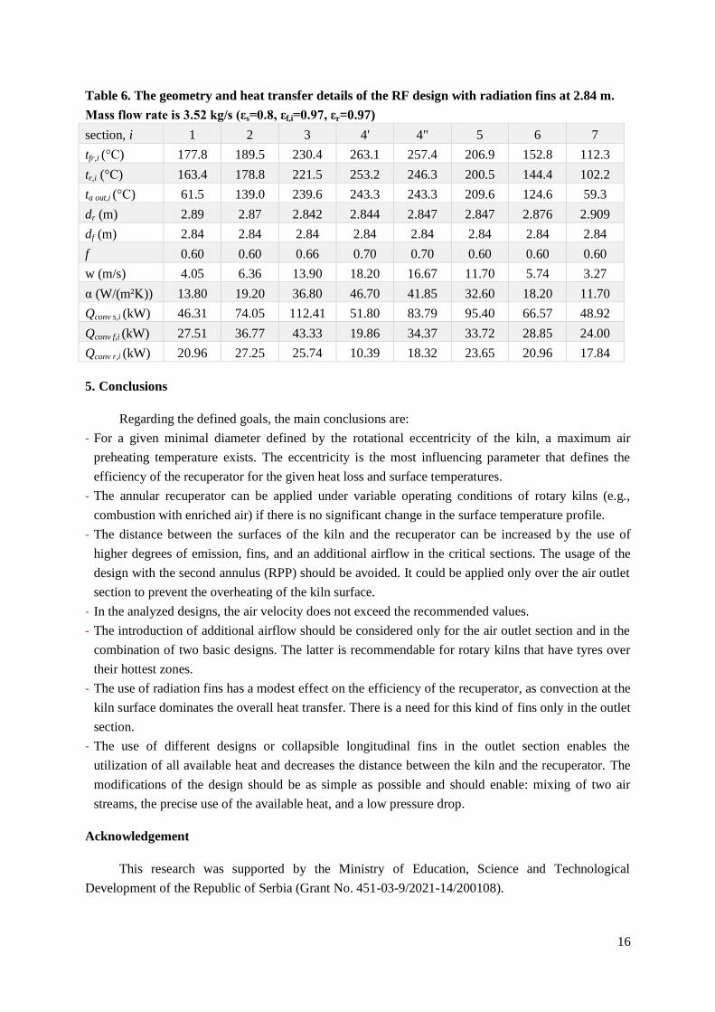
Unlike the RPP design, the introduction of radiation fins (see fig. 2 b)) has a positive effect on
the critical diameter. Compared with the basic design with the minimal diameter of 2.84 m (see fig. 5
a), RF (see fig. 2 b) and tab. 6) with the fins at the diameter of 2.84 m has more than 30 °C higher
preheating temperature. A larger surface area for the convective heat transfer causes the improvement.
Compared with the basic design, the surface area is more than 60% larger, but the benefit is modest
because the majority of the heat loss is transferred to the air by convection at the kiln surface. The kiln
shell temperature limits the impact of thermal radiation. It decreases with the rise of air temperature.
Tab. 6 shows that the distance between the radiation fin and the recuperator becomes very small near
the exit. That suggests that instead of the use of radiation fins, the recuperator surface should be finned
in the outlet sections. In fact, in the air outlet sections preferable option is the application of fins on the
kiln surface.
16
Table 6. The geometry and heat transfer details of the RF design with radiation fins at 2.84 m.
Mass flow rate is 3.52 kg/s (εs=0.8, εf,i=0.97, εr=0.97)
section, i 1 2 3 4' 4" 5 6 7
tfr,i (°C) 177.8 189.5 230.4 263.1 257.4 206.9 152.8 112.3
tr,i (°C) 163.4 178.8 221.5 253.2 246.3 200.5 144.4 102.2
ta out,i (°C) 61.5 139.0 239.6 243.3 243.3 209.6 124.6 59.3
dr (m) 2.89 2.87 2.842 2.844 2.847 2.847 2.876 2.909
df (m) 2.84 2.84 2.84 2.84 2.84 2.84 2.84 2.84
f 0.60 0.60 0.66 0.70 0.70 0.60 0.60 0.60
w (m/s) 4.05 6.36 13.90 18.20 16.67 11.70 5.74 3.27
α (W/(m²K)) 13.80 19.20 36.80 46.70 41.85 32.60 18.20 11.70
Qconv s,i (kW) 46.31 74.05 112.41 51.80 83.79 95.40 66.57 48.92
Qconv f,i (kW) 27.51 36.77 43.33 19.86 34.37 33.72 28.85 24.00
Qconv r,i (kW) 20.96 27.25 25.74 10.39 18.32 23.65 20.96 17.84
5. Conclusions
Regarding the defined goals, the main conclusions are:
- For a given minimal diameter defined by the rotational eccentricity of the kiln, a maximum air
preheating temperature exists. The eccentricity is the most influencing parameter that defines the
efficiency of the recuperator for the given heat loss and surface temperatures.
- The annular recuperator can be applied under variable operating conditions of rotary kilns (e.g.,
combustion with enriched air) if there is no significant change in the surface temperature profile.
- The distance between the surfaces of the kiln and the recuperator can be increased by the use of
higher degrees of emission, fins, and an additional airflow in the critical sections. The usage of the
design with the second annulus (RPP) should be avoided. It could be applied only over the air outlet
section to prevent the overheating of the kiln surface.
- In the analyzed designs, the air velocity does not exceed the recommended values.
- The introduction of additional airflow should be considered only for the air outlet section and in the
combination of two basic designs. The latter is recommendable for rotary kilns that have tyres over
their hottest zones.
- The use of radiation fins has a modest effect on the efficiency of the recuperator, as convection at the
kiln surface dominates the overall heat transfer. There is a need for this kind of fins only in the outlet
section.
- The use of different designs or collapsible longitudinal fins in the outlet section enables the
utilization of all available heat and decreases the distance between the kiln and the recuperator. The
modifications of the design should be as simple as possible and should enable: mixing of two air
streams, the precise use of the available heat, and a low pressure drop.
Acknowledgement
This research was supported by the Ministry of Education, Science and Technological
Development of the Republic of Serbia (Grant No. 451-03-9/2021-14/200108).

17
Nomenclature
surface area, [m2]
the total area of the openings on a
radiation fin in the i-th section, [m2]
the total surface area of the radiation fin
in the i-th section, [m2]
specific heat capacity of air at constant
pressure, [kJkg-1
K-1
]
external diameter of the kiln, 2.8m
hydraulic diameter, [m]
minimal (critical) diameter of the
recuperator, [m]
, , diameters defined in
Fig. 3, [m]
view factor, -
relative closedness of the fin, -
length, [m]
mass flow rate, [kg/s]
Nusselt number, -
Prandtl number, -
heat loss, [kW]
heat flow rate, [kW]
radiative heat flow rate, [kW]
Reynolds number, -
cells (see Fig. 3. a))
temperature, [°C]
temperature, [K]
air velocity, [m/s]
W1,., Wn uncertainties, -
x1,., xn independent variables, -
Greek letters
convective heat transfer coefficient,
[Wm-2
K-1
]
emissivity, -
thermal conductivity, [Wm-1
K-1
],
Steffan-Boltzmann coefficient, 5.67∙10-8
[Wm-2
K-4
],
density, [kg/m3],
Subscripts
a air,
Al aluminum,
conv convection,
FG flue gas,
f fin,
i i-th section or insulation,
,i in the i-th section of the recuperator,
(i-1) in the upstream cell,
(i+1) in the downstream cell,
i+1 upstream section,
i-1 downstream section,
in designates quantity that enters,
io the outer surface of the insulation,
m modified,
,m mean,
o ambient or outer
out designates all streams leaving the kiln, or
air leaving the i-th section of the
recuperator,
O2 oxygen,
p preheating,
r recuperator,
rad radiation,
s designates the outer surface of the kiln
s,i i-th section of the kiln outer surface,
steel steel,
1 or R1 inner segment in the RPP design,
2 or R2 outer segment in the RPP design.
References
[1] Karamarković, V., et al., Recuperator for waste heat recovery from rotary kilns, Appl. Therm.
Eng, 54 (2013), pp. 470-480
[2] Vijayan, S.N., Sendhilkumar , S., Industrial Applications of Rotary Kiln in Various Sectors - A
Review, Int. J. Eng. Innov. Res. 3 (2014), pp. 342–345
[3] Golewski, G.L., Energy savings associated with the use of fly ash and nanoadditives in the
cement composition, Energies 2020, 13(9), 2184, pp. 1-20
18
[4] U.S.G. Survey, National Minerals Information Center, (n.d.).
https://www.usgs.gov/centers/nmic/mineral-commodity-summaries
[5] Caputo, A.C., et al., Performance modeling of radiant heat recovery exchangers for rotary kilns,
Appl. Therm. Eng. 31 (2011), pp. 2578–2589
[6] Chakrabati, B., Investigations on heat loss through the kilne shell in magnesite dead burning
process: a case study., Appl. Therm. Eng. 22 (2002) , pp. 1339–1345
[7] Sadighi Sepehr, A.A., Mansoor, S., Rotary cement kiln coating estimator: Integrated modelling
of kiln with shell temperature measurement, Can. Jouranl Chem. Eng. 89 (2011) 116–125
[8] Engin, T., Ari, V., Energy auditing and recovery for dry type cement rotary kiln systems - a case
study, Energy Convers. Manag. 46 (2005) , pp. 551–562
[9] Kabir, G., et al., Energy audit and conservation opportunities for pyroprocessing unit of a
typical dry process cement plant, Energy. 35 (2010) , pp. 1237–1243
[10] Luo, Q., et al., A Thermoelectric Waste-Heat-Recovery System for Portland Cement Rotary
Kilns, J. Electron. Mater. 44 (2015) , pp. 1750–1762
[11] Mirhosseini, M., et al., Power optimization and economic evaluation of thermoelectric waste
heat recovery system around a rotary cement kiln, J. Clean. Prod. 232 (2019) , pp. 1321–1334
[12] Mittal, A., Rakshit, D., Energy audit and waste heat recovery from kiln hot shell surface of a
cement plant, Therm. Sci. Eng. Prog. 19 (2020) 100599
[13] Du, W.J., et al., Experiments on novel heat recovery systems on rotary kilns, Appl. Therm. Eng.
139 (2018) , pp. 535–541
[14] Yin, Q., et al., Optimization design and economic analyses of heat recovery exchangers on
rotary kilns, Appl. Energy. 180 (2016), pp. 743–756
[15] Yin, Q., et al., Design requirements and performance optimization of waste heat recovery
systems for rotary kilns, Int. J. Heat Mass Transf. 93 (2016) , pp. 1–8
[16] Akram, N., et al., Improved waste heat recovery through surface of kiln using phase change
material, Therm. Sci. 22 (2018), pp. 1089–1098
[17] Zheng, K., et al., Rotary kiln cylinder deformation measurement and feature extraction based on
EMD method, Eng. Lett. 23 (2015), pp. 283–291
[18] Mirzakhani, M.A., et al., Energy benchmarking of cement industry, based on Process
Integration concepts, Energy. 130 (2017), pp. 382–391
[19] Churchill W, C.H., Correlating equations for laminar and turbulent free convection from a
horizontal cylinder, Int. J. Heat Mass Transf. 18 (1975), pp. 1049–1053
[20] Werner Kast, H.K., Heat Transfer by Free Convection: External Flows, in: VDI Heat Atlas, 2nd
ed., Springer, Heidelberg, 2010: pp. 667–672
[21] Kabelac, D., Vortmeyer, S., Radiation of Surfaces, in: VDI Heat Atlas, Heidelberg, 2010: pp.
947–959
[22] Faculty of Mechanical Engineering in Kraljevo, The impact of the usage of enriched air for
combustion on kiln production. (in Serbian), 2012
[23] Gnielinski, V., Forced Convection, in: VDI Heat Atlas, 2nd ed., Heidelberg, 2010: pp. 691–699
[24] Gnielinski, V., New equations for heat and mass transfer in turbulent pipe and channel flow, Int.
J. Chem. Eng. 16 (1976), pp. 359–368
[25] Janna, S.W., Engineering Heat Transfer 3rd Edition, 2009
[26] Vormeyer, K.S., Dieter, View Factors, in: VDI Heat Atlas, Heidelberg, 2010: pp. 961–978
19
[27] Knežević, D. S., et al., Radiant recuperator modeling and design, Therm. Sci. 21 (2017), pp.
1119-1134
[28] Kleiber, M., Joh, R., Calculation Methods for Thermopysical Properties, in: VDI Heat Atlas,
2nd ed., Springer, Heidelberg, Germany, 2010: pp. 121–152
[29] Kleiber, M., Joh, R., Properties of Selected Importanat Pure Substances, in: VDI Heat Atlas, 2nd
ed., Heidelberg, Germany, 2010: pp. 153–299
[30] Kleiber, M., Joh, R., Properties of Pure Fluid Substances, in: VDI Heat Atlas, 2nd ed.,
Heidelberg, Germany, 2010: pp. 301–417
[31] Sofialidis, D., Boundary Conditions & Solver Settings, (2013) 61. https://events.prace-
ri.eu/event/156/contributions/6/attachments/65/89/Fluent-
Intro_14.5_L02_BoundaryConditionsSolverSettings.pdf
[32] Moffat, R.J., Describing the uncertainties in experimental results, Exp. Therm. Fluid Sci. 1
(1988), pp. 3–17
[33] E. ToolBox, Velocity Classification of Ventilation Ducts, (2003).
https://www.engineeringtoolbox.com/velocities-ventilation-ducts-d_211.html
Submitted: 10.04.2021. Revised: 12.07.2021. Accepted: 14.07.2021.