improving engine efficiency through core …
TRANSCRIPT

IMPROVING ENGINE EFFICIENCY THROUGH CORE DEVELOPMENTS
Brief summary: The NASA Environmentally Responsible Aviation (ERA) Project and Fundamental Aeronautics Projects are supporting compressor and turbine research with the goal of reducing aircraft engine fuel burn and greenhouse gas emissions. The primary goals of this work are to increase aircraft propulsion system fuel efficiency for a given mission by increasing the overall pressure ratio (OPR) of the engine while maintaining or improving aerodynamic efficiency of these components. An additional area of work involves reducing the amount of cooling air required to cool the turbine blades while increasing the turbine inlet temperature. This is complicated by the fact that the cooling air is becoming hotter due to the increases in OPR. Various methods are being investigated to achieve these goals, ranging from improved compressor three-dimensional blade designs to improved turbine cooling hole shapes and methods. Finally, a complementary effort in improving the accuracy, range, and speed of computational fluid mechanics (CFD) methods is proceeding to better capture the physical mechanisms underlying all these problems, for the purpose of improving understanding and future designs.

National Aeronautics and Space Administration
www.nasa.gov
Improving Engine Efficiency Through Core Developments
AIAA Aero Sciences Meeting
January 6, 2011
Dr. James Heidmann
Project Engineer for Propulsion Technology (acting)
Environmentally Responsible Aviation
Integrated Systems Research Program

NASA’s Subsonic Transport System Level Metrics…. technology for dramatically improving noise, emissions, & performance
Noise
(cum below Stage 4)
-60% -75% better than -75%
-33% -50% better than -70%
-33% -50% exploit metro-plex* concepts
N+1 = 2015
Technology Benefits Relative
To a Single Aisle Reference
Configuration
N+2 = 2020
Technology Benefits Relative
To a Large Twin Aisle
Reference Configuration
N+3 = 2025
Technology Benefits
LTO NOx Emissions
(below CAEP 6)
Performance:
Aircraft Fuel Burn
Performance:
Field Length
-32 dB -42 dB -71 dB
CORNERS OF THE
TRADE SPACE
2
Goals are relative to reaching TRL 6 by the timeframe indicated
Engine core research primarily focused on fuel burn metric (SFC)
Core developments have positive and negative impacts on NOx

POTENTIAL REDUCTION IN FUEL CONSUMPTIONAdvanced N+2 Configurations
Advanced Configuration #1N+2 “tube-and-wing“
2025 EIS (TRL=6 in 2020)
Advanced Configuration #2AN+2 HWB300
2025 EIS (TRL=6 in 2020)
Advanced Configuration #2BN+2 HWB300
2025 EIS (TRL=6 in 2020 assumingaccelerated technology development)
-139,400 lbs(-49.8%)
-151,300 lbs(-54.1%)
Fuel Burn = 140,400 lbs Fuel Burn = 128,500
lbs
Embedded Engines withBLI Inlets ∆ Fuel Burn = -3.2%
Advanced EnginesΔ Fuel Burn = -15.3%
-120,300 lbs
(-43.0%)
Fuel Burn = 159,500 lbs
Advanced EnginesΔ Fuel Burn = -18.5%
Advanced EnginesΔ Fuel Burn = -16.0%
-43.0%
-49.8%-54.1%

Propulsion Technology Enablers
Fuel Burn - reduced SFC (increased BPR, OPR &
turbine inlet temperature, potential embedding benefit)
Velocity
TSFC
Lift
Dragln
Wfuel
WPL + WO
=
•Aerodynamics • Empty Weight • Engine Fuel
Consumption
Aircraft
Range1 +
Velocity
TSFC
Lift
Dragln
Wfuel
WPL + WO
=
•Aerodynamics • Empty Weight • Engine Fuel
Consumption
Aircraft
Range1 +
TSFC = Velocity / (ηoverall)(fuel energy per unit mass)
ηoverall = (ηthermal)(ηpropulsive)(ηtransfer)(ηcombustion)
Core research impacts thermal efficiency through increased OPR
High power density cores enable higher propulsive efficiency cycles
Low pressure turbine improvements impact transfer efficiency
assuming constant
component efficiencies

Propulsion system improvements require advances in both
propulsor and core technologies
Core
Improvements
(direct impact on LTO NOx)
Propulsor
improvements
Propulsion Technology Opportunity

6
Cycle Performance Improves with Temperature

500
600
700
800
900
1000
1100
1200
1300
1400
1500
1600
1700
1800
1930 1940 1950 1960 1970 1980 1990 2000
AERO-ENGINE
INDUSTRIAL GT
Temp. at Rotor Inlet
CFM56
E3
701F
TRENT
CF6-80
F100
F101
XF3-20 F3-30
F110
MF111
F404
PW2037
H-25 7001F
9001F TEPCO
V2500
AGTJ100BCFM56-5
501F
9001G,H
7001G,H
F100-PW-299
XG40
M-88HYPRA
HYPRB
PW4000GE90 701G
501G
CGTAGTJ100A
JR220
TF39
BBC4000kW1GO
BBC900kWKO-7
HeS3B NE-20
BMW003
W2/700
J69
J73
Dart10
Conway
T56-14
AvonJT3D
CT610 J3-7
T64
J79-17
JT8D
JR100
501AA
7001B
JT15D
TFE731
9001B
TF40
TF30
CF6-6CF6-50
RB199
FJR710/600
FJR710/20
FJR710-10
JT9D-3
RB211-22
7001E 9001E
701D
JT9D-7R4
501D
501B
W1
JUMO004-1J3
YEAR
TU
RB
INE
IN
LE
T T
EM
PE
RA
TU
RE
[℃
]
F.WhittlePAT
From Dr. Toyoaki Yoshida, National Aerospace Laboratory, Japan
Engine Thermal Trends

8
Turbine Materials Improvements
Increase in operational temperature of turbine components.
After Schulz et al, Aero. Sci. Techn.7:2003, p73-80.

9
Turbine Cooling Improvements

10
Turbomachinery Aero Design-Based Tech Enablers
Highly-Loaded,
Multistage
Compressor (higher
efficiency and OPR)
Low-Shock
Design, High
Efficiency,
High Pressure
Turbine
Aspiration Flow
Controlled,
Highly-Loaded,
Low Pressure Turbine
High-Efficiency
Centrifugal
Compressor
(small high
efficiency core)
Low Pressure
Turbine
Plasma Flow
Control
FLOW
z
FLOW
z
UW
FLOW
UW
FLOW
Novel Turbine
Cooling Concepts
11
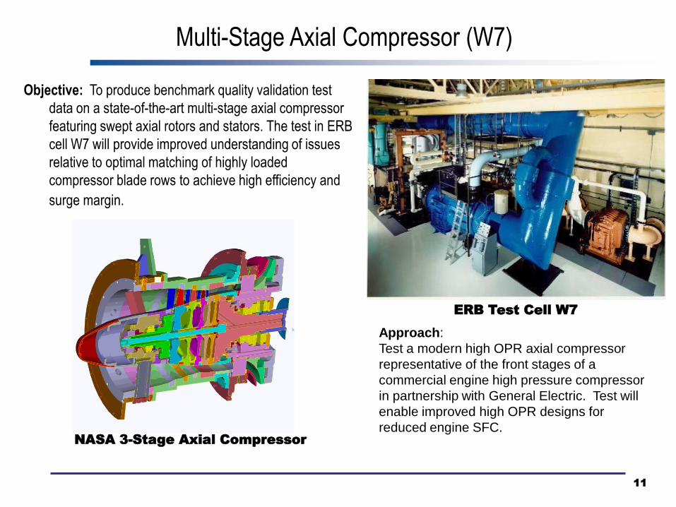
Objective: To produce benchmark quality validation test
data on a state-of-the-art multi-stage axial compressor
featuring swept axial rotors and stators. The test in ERB
cell W7 will provide improved understanding of issues
relative to optimal matching of highly loaded
compressor blade rows to achieve high efficiency and
surge margin.
ERB Test Cell W7
Approach:
Test a modern high OPR axial compressor
representative of the front stages of a
commercial engine high pressure compressor
in partnership with General Electric. Test will
enable improved high OPR designs for
reduced engine SFC.NASA 3-Stage Axial Compressor
Multi-Stage Axial Compressor (W7)

12
86.0%
86.5%
87.0%
87.5%
88.0%
88.5%
89.0%
89.5%
90.0%
CFD prediction apply delta, CFD
to data
increase inlet
radius ratio
scale from rig to
engine
TT
po
lytr
op
ic e
ffic
ien
cy
Engine
scale
polytropic
efficiency is
estimated
as 87.9 -
88.9%
UTRC NRA – High Efficiency Centrifugal Compressor (HECC)
m = 10.1 lbm/s
Opportunity for
improved rotary wing
vehicle engine
performance as well
as rear stages for
high OPR fixed wing
application

Turbine Film Cooling Experiments
Objective: Fundamental study of heat transfer and flow field
of film cooled turbine components
Rationale: Investigate surface and flow interactions
between film cooling and core flow for various large scale
turbine vane models
Approach: Obtain detailed flow field and heat transfer data
and compare with CFD simulations
Trailing
Edge Film
Ejection:
IR images
Large Scale Film Hole:
Film cooling jet
downstream of hole
Vane Heat Transfer:
Good agreement between
GlennHT and experiment

14
Anti-Vortex Film Cooling Concept
Auxiliary holes (yellow) produce counter-
vorticity to promote jet attachment
Advantages: Inexpensive due to use of only
round holes, hole inlet area unchanged
Flow Direction
Front View
Side View
Comparison of round hole and “anti-vortex”
turbine film cooling jet attachment
Top View

FLOW
FLO
W
COFFING
4 TON
HOIST
15
Turbine Testing in NASA Glenn Single Spool Turbine Facility (W6)
Unique High-Speed High Pressure Ratio Capability
NASA/General Electric Highly-Loaded Turbine Tests

16
Conventional HPT Reduced Shock Design
Pressure Ratio (PTR/PS) = 3.25
Stage Pressure Ratio = 5.5
HPT: Reduced Shock Design
LPT: Flow-Controlled Stator & Contoured Endwall
NASA/General Electric Highly-Loaded Turbine Tests
Enables efficient high overall pressure ratio turbine capability
with reduced cooling flow and reduced SFC

17
INSULATOR
ELECTRODE
ELECTRODE
DBD PLASMA
Electrode perpendicular to flow
Active Flow Control via
Oscillating wall jet
FLOW
U
W
Electrode parallel to flow
Active Flow Control via
Streamwise vortices
FLOW
z
Dielectric Barrier Discharge Plasma Actuators
Advantages of GDP actuators:
• Pure solid state device
• Simple, no moving parts
• Flexible operation, good for varying
operating conditions
• Low power
• Heat resistance – w/ proper materials
APPLIED
VOLTAGE
“WIND”
2.7 5.3 8.0 10.7
10
20
30
40
Force, mN/m
Bias Voltage, p-to-p, kV
PR
R, kH
z
0
1.500
3.000
4.500
6.000
7.500
9.000
10.50
12.00
0 10 20 30 40 50
0
1
2
3
4
5
6
7
8
9
10
11
12
Bias Voltage,
p-to-p, kV
Fo
rce
, m
N/m
PRR, kHz
1.4
2.7
4.0
5.3
6.7
8.0
9.3
10.7
11.0
Princeton Nanosecond Pulsing NRA
Large force induced with voltage bias
Force Versus Pulse Repetition Rate & Bias
Low pressure turbine flow control – reduced weight and improved efficiency

18
1
8
CMC Engine Components Reduce Cooling Air Requirements
CombustorHigh Pressure Low Pressure
Exhaust NozzleTurbine Turbine
Temperature 2200-2700°F 2400-2700°F 2200-2300°F 1500-1800°F
CMC System SiC / SiC SiC / SiC SiC / SiC Oxide / Oxide
Engine Benefit
• Reduced cooling • Reduced cooling • Reduced cooling • Light weight
• Reduced NOx • Reduced SFC • Strength / weight • Noise reduction
• Pattern Factor • Higher use temp
Challenges
• Durability • Manufacturing • Manufacturing• Manufacturing
• Attachment & • Durability • Durability
Integration • Attachment & • Attachment &• Durability
Integration Integration

CMC Turbine Vane Reduces Fuel Burn
Prepreg lay-up assembly
• Hi-Nic type S fibers
• BN interface coatings
• Balanced ply lay-up
• 0/90o tapes
• Fiber volume ~ 28%
CVI SiC with MI SiC
• Hi-Nic Type S fibers
• CVI BN fiber coatings
• 5 harness satin weave
• Fiber volume ~ 35%
19
Durability comparison of candidate CMC material systems planned for 2011

20
CMC (Ceramic Matrix Composite)• ATK COIC Oxide/Oxide CMC:
AS-N610 (Aluminosilicate matrix, Nextel 610 fabric reinforcement)
• Composition: 51% fiber, 24% matrix, 25% open porosity
• NASA teaming with Rolls Royce/LibertyWorks on CMC exhaust mixer nozzle development
• Subscale aero-rig component testing (<12” dia.) • Example of a similar article fabricated by ATK
COIC shown. • Structural benchmark testing at NASA GRC, with
stress & failure model validation to follow.
18-inch dia. CMC Mixer Demonstration Article
CMC Nozzle Reduces Weight, Increases Temperature Capability, Potential Noise Benefit

Core Engine Research Summary
Core turbomachinery research directly impacts fuel burn reduction goals of ERA
and other NASA Aeronautics projects
Compressor research focused on increasing overall pressure ratio while
maintaining or improving aerodynamic efficiency
Turbine research focused on increased loading, reduced cooling flows, and
improved aerodynamic efficiency
High OPR axial compressor testing with General Electric
Centrifugal compressor testing with United Technologies Research Center
Highly-loaded HPT testing with General Electric
Fundamental testing of turbine cooling flows and low pressure turbine flow control
with universities and Department of Energy
Computational fluid dynamic development and assessment across all
components, including advanced turbulence models such as LES and DNS