improving loss resilience with multi-radio diversity...
TRANSCRIPT

Improving Loss Resilience with Multi-Radio Diversity inWireless Networks
Allen Miu, Hari Balakrishnan, and Can Emre Koksal∗MIT Computer Science and Artificial Intelligence Laboratory
The Stata Center, 32 Vassar StreetCambridge, MA 02139
{aklmiu, hari}@csail.mit.edu, [email protected]
This paper describes the Multi-Radio Diversity (MRD)wireless system, which uses path diversity to improve lossresilience in wireless local area networks (WLANs). MRDcoordinates wireless receptions among multiple radiosto improve loss resilience in the face of path-dependentframe corruption over the radio. MRD incorporates twotechniques to recover from bit errors and lower the lossrates observed by higher layers, without consuming muchextra bandwidth. The first technique is frame combining,in which multiple, possibly erroneous, copies of a givenframe are combined together in an attempt to recover theframe without retransmission. The second technique isa low-overhead retransmission scheme called request-for-acknowledgment (RFA), which operates above the linklayer and below the network layer to attempt to recoverfrom frame combining failures. We present an analysis thatdetermines how the parameters for these algorithms shouldbe chosen.
We have designed and implemented MRD as a fully func-tional WLAN infrastructure based on 802.11a. In ourtestbed, we measured throughput gains up to 2.3× oversingle radio communication schemes employing 802.11’s au-torate adaptation scheme.
Categories and Subject DescriptorsComputer Systems Organization [Computer-Communications Networks]: Network Architectureand Design—Wireless Communication
General TermsMeasurement, Performance, Design, Experimentation
∗Computer and Communication Sciences, EPFL, Switzer-land.
Permission to make digital or hard copies of all or part of this work forpersonal or classroom use is granted without fee provided that copies arenot made or distributed for profit or commercial advantage and that copiesbear this notice and the full citation on the first page. To copy otherwise, torepublish, to post on servers or to redistribute to lists, requires prior specificpermission and/or a fee.MobiCom’05, August 28–September 2, 2005, Cologne, Germany.Copyright 2005 ACM 1-59593-020-5/05/0008 ...$5.00.
Keywordspath diversity, packet combining, frame combining, bit-error, wireless LAN, wireless networks, performance
1. INTRODUCTIONThis paper describes the design and implementation of
the Multi-Radio Diversity (MRD) system, which reduces theloss rate and improves the throughput observed by transportprotocols and applications running over wireless local areanetworks (WLANs). Our approach uses path diversity, rely-ing on multiple access points (APs) covering a given area (foruplink diversity) and multiple radios on the user’s device (fordownlink diversity). The hypothesis underlying this systemis as follows: because frame losses are often path-dependent(e.g., due to multi-path fading), location-dependent (e.g.,due to noise), and statistically independent between differ-ent receiving radios, multiple radios that all receive versionsof the same transmission may together be able to correctlyrecover a frame, even when any given individual radio is not.
Most current WLAN deployments (e.g., those based on802.11 [6]) use one or more APs that relay packets to andfrom a WLAN client. Each AP operates independently andeach WLAN client can communicate with only one AP ata time. Because the properties of a single path vary withtime and can undergo severe deterioration, the result is thatcommunication often suffers from high packet loss rates, longdelays, and even outages. These, in turn, degrade the per-formance of protocols like TCP and applications like mobileInternet telephony, streaming audio/video, and games.
In MRD, different APs with overlapping coverage and lis-tening on the same radio frequency provide alternate com-munication paths for each frame transmission from a givenWLAN client, while multiple wireless cards on the WLANclient achieve the same result for transmissions to the client.MRD coordinates packet receptions across the different ra-dios to improve loss resilience against path-dependent bitcorruption. The idea is simple: even when each individualreception of a data frame is erroneous, it might be possibleto combine the different versions to recover the correct ver-sion of the frame. In MRD, the entity that performs thisframe combining task is the MRD Combiner (MRDC).
MRD’s frame combining algorithm divides each frameinto blocks. For each block, the algorithm assumes thatat least one of the received copies of a frame (includingany possible retransmissions) contains the correct bit val-ues for that block. The algorithm then attempts to recon-

struct the correct frame by trying every version received foreach block. The process succeeds if a particular block com-bination passes the checksum embedded in the data frame,and fails once the search exhausts all possible block choicesfor each block. The computational complexity of this al-gorithm is exponential in the number of blocks for whichdifferent versions were received, which depends on the num-ber of blocks in each frame. We show how to pick the blocksize and evaluate its performance using theoretical analysisand real-world experiments. This approach to frame com-bining is reminiscent of an old, well-studied idea called “re-transmissions with memory” [31, 13], where retransmissionsof erroneous frames are combined with the original trans-mission in an attempt to recover the correct version of thedata. Our contribution is to generalize this idea using ablock-based technique to incorporate the spatial dimensionas well.
The MRDC can often recover a corrupt frame withoutrequiring a retransmission from the client, but frame com-bining will not always succeed. MRD uses a lightweightretransmission scheme running above the WLAN link layerto further improve error recovery. At the sender, the MRDSender (MRDS) buffers all frames that have not yet beenacknowledged (or given up on), and retransmits any framethat it believes has not been successfully received by theMRDC (after frame combining). To prevent adverse interac-tions caused by ARQ schemes at two different layers, MRDturns off link-layer retransmissions altogether. To keep over-head low and to react quickly to channel contention, how-ever, MRD uses two techniques: first, it retains 802.11’s syn-chronous ACK mechanism, with the MRDS clearing framesthus acknowledged from its retransmission buffer. But be-cause some frames can only be recovered after frame com-bining, and because the MRDC does not know whether anygiven link-layer ACK reached the MRDS, MRD uses a feed-back protocol between the MRDC and MRDS. This protocolis designed to have low overhead, using a request for ACK(RFA) technique rather than traditional ACKs or NACKs.With RFA, the MRDS explicitly requests an ACK from theMRDC for certain frames, and decides whether and whento retransmit frames based on this feedback.
A noteworthy aspect of MRD is that it achieves significantimprovements in loss rates while consuming only a smallamount of additional bandwidth. As a result, it comple-ments both automatic repeat request (ARQ) and rate adap-tation [1, 10, 20], two common error-control techniques usedin contemporary WLANs. ARQ-based retransmissions workwell when the duration of channel degradation is short. Butwhen the channel’s quality deteriorates for a long period,link-layer retransmissions triggered by a missing link-layerACK become ineffective and wasteful. Rate adaptation, onthe other hand, can work well even when the wireless chan-nel experiences severe deterioration. However, efficient rateadaptation is difficult to achieve when channel conditionsvary quickly and unpredictably, as is the case in many real-world WLANs, particularly when users are mobile.
Sections 2 through 5 of this paper detail the different con-tributions of this paper: the MRD architecture, the framecombining algorithm and its theoretical analysis, the RFAscheme, and the MRD modifications to the 802.11 WLANrate adaptation schemes. Section 6 describes our fully func-tional 802.11a/b/g-based Linux implementation of MRD.Section 7 presents the results of several experiments con-
ducted over an in-building 802.11a-based testbed at MIT’sComputer Science and Artificial Intelligence Laboratory.Experiments that experienced a high channel variability(e.g., a mobile WLAN client that moved over a relativelysmall area of about three square meters) show through-put improvements of up to 2.3× compared to contemporary802.11a with “autorate adaptation” [1].
2. MULTI-RADIO DIVERSITY ARCHI-TECTURE
AP …
Wired Backbone
Rest of Network
APAP
WLAN Infrastructure
MRDC
MRDS
WLAN Client
Figure 1: MRD system architecture.
For ease of exposition, we describe the MRD architecturein the context of uplink transmissions from the client to theWLAN infrastructure. The same architecture can be usedwhen the MRD radios are co-located on the same device(either in a single AP or on the WLAN client).
Figure 1 shows the MRD system architecture. Each AP inthe WLAN infrastructure offers a different physical commu-nication path to the client. We configure the APs to listenon the same radio frequency so they can each receive a copyof the client’s uplink transmission. The AP forwards allframes—including those that are corrupted—to the MRDCombiner (MRDC), which filters redundant data frames re-ceived by multiple radios and invokes the frame combiningprocedure when needed. The MRDC maintains a packetbuffer to in-order packet delivery to the rest of the network.
At the WLAN client sender, the MRDS handles datatransmissions and retransmissions. The MRDS operates inbetween the link-layer and the IP network layer. It keepstrack of unacknowledged transmissions and schedules theirretransmissions when it believes that the MRDC has failedto receive a clean copy of the transmitted frame from any ofthe APs or has failed to correct their errors frame combin-ing. The MRDS uses the request-for-ACK (RFA) protocolto obtain the results of the frame combining procedure fromthe MRDC.
The MRD WLAN architecture does not preclude cellularfrequency reuse. Frequency reuse is a common method toincrease network capacity, which requires APs in neighbor-ing cells to operate in different radio frequencies. In MRD,the APs that are not explicitly associated with the clientneed only listen for uplink transmissions passively. Thus,one strategy to achieve frequency reuse is to install passiveradios in addition to the regular, active radio at each AP.1
1In fact, companies have begun selling radio chipsets that

The client associates with the active radio at each AP, whichserves the regular function of transmitting management andcontrol frames to the WLAN client, while the passive radiosare configured to listen on the neighbors’ radio frequencies.Because the passive radios never transmit a frame, they donot create any interference in the network. If installing mul-tiple radios on a single AP is not possible, an operator caninstall additional passive access points in the network. Asthe costs of APs continue to decline, this approach is a vi-able way to add path diversity (for uplink communication)in WLANs.
MRD assumes that there is sufficient bandwidth in thewired backbone to handle the additional traffic generatedby the passive APs. This assumption is reasonable becausethe number of APs within reception range of a transmitter isusually low and the speed of the wired backbone is usuallyat least one or two orders of magnitude higher than thewireless link.
MRD does not affect the functions of handoff and secu-rity in a WLAN. The WLAN client would associate with andhandoffs between different APs using their active radios. Ex-isting WLAN security standards such as WEP [6], 802.1x [7],and WPA/802.11i [4] handle encryption/decryption andother security functions in software and are easily imple-mented in the MRDS and the MRDC, assuming that theMRDC can establish a secure trust relationship with eachMRD radio in the network.
3. FRAME COMBININGWe describe how MRD recovers error-free versions of cor-
rupted data frames and analyze its performance. One ap-proach is to run a simple linear time algorithm that attemptsto correct bit errors by selecting the majority bit value be-tween three or more frames [14]. But this approach requiresat least three copies of the same transmitted frame, whichmay not be available (without a retransmission) in the casewhen only two MRD radios are within receiving range of thesender. Therefore, we develop and analyze a block-basedframe combining scheme that can work even when only twocopies are available.
Suppose two copies of the same transmitted frame of sizeS bits are received at two different receivers. Before framecombining, if any of the data frames passes the link-layercyclic redundancy checksum (CRC) check, it is decoded asthe transmitted frame and forwarded (soft selection). Oth-erwise, we run the block-based combining algorithm to re-cover the packet. Block-based frame combining works byfirst subdividing both frames into blocks, and then recon-structing the frame by assembling the blocks selected fromeach received frame of the transmitted packet. The processsucceeds if a block combination passes the CRC embeddedin the data frame, and fails once the search exhausts allpossible block combinations. We provide a summary of theblock combining algorithm below:
1. The input of the algorithm is two frames f ={A,B} of size S, divided into fixed-sized blocks X =
{Xf1 ,X
f2 , ..., X
fNB}. Let ∆ = |{i|XA
i ⊕XBi �= 0}| (i.e.,
the number of blocks that do not have matching bitvalues).
can process and decode transmissions from multiple chan-nels simultaneously (see, e.g., [3]).
0 2000 4000 6000 8000 10000 120000
50
100
150
200
250
Bit Location
Cou
nt
R1(18558 frames)
R2(17524 frames)
(a) Bit-error locationhistogram
100
101
102
103
0
0.1
0.2
0.3
0.4
0.5
Lag(bits)
Con
ditio
nal P
roba
bilit
y
p( R1i+k
| R1i )
p( R2i+k
| R2i )
p( R1i+k
| R2i )
p( R2i+k
| R1i )
(b) Bit-error condi-tional probabilities
Figure 2: Bit-error analysis. Figure 2(a) showsthat the bit-errors are clustered in a regular patternwithin a frame. The number in the legend indicatesthe number of corrupt frames received at each node.The conditional probabilities in Figure 2(b) suggestthat bit-errors occur in bursts within a frame butbit-errors between frames received at different loca-tions have low correlation.
2. Assemble a combined frame that contains X ′ ={Xf ′
1 ,Xf ′2 , ..., X
f ′NB} blocks from either frame A or B.
Each iteration of this step generates a new combined
frame by replacing Xf ′i with either XA
i or XBi for each
i where XAi ⊕XB
i �= 0.
3. If either of the CRC value embedded in frames A orB matches the CRC value computed over X ′, returnthe combined frame containing X ′. Otherwise, repeatstep 2 until all possible combinations of X ′ have beentried. If none of the block combinations X ′ passes theCRC check, declare a frame combining failure.
There are many ways of dividing a frame into roughlyfixed-size blocks. For simplicity, we divide each frame suchthat blocks Xf
1 ,Xf2 , ..., X
fNB−1 contain B bits and the size
of the last block |XfNB| is 6 B. Thus, NB = S/B.
When the block-based frame combining algorithm de-clares a failure, the MRDC can save the corrupt frames forpossible frame combining (using either bit-majority or block-based combining) with any subsequent retransmissions ofthe frame. In our current implementation, the MRDC savesonly one of the corrupt frames and apply block-based com-bining to two corrupt frames at a time.
The block-based frame combining algorithm is simple butits running time is exponential in ∆, the number of differ-ing blocks. With two copies, it needs up to about 2∆ CRCcheck operations to identify the correct combination. Since∆ ≤ NB , one way to bound the number of CRC checks isto reduce NB by increasing B. Inevitably, the frame com-bining failure probability will increase as the likelihood ofsimultaneous block errors increases with B. We evaluatethis tradeoff next.
3.1 Frame Combining FailureWe analyze how the frame combining failure probability,
pf , varies with NB under a burst bit-error channel modelparameterized by a burst length b. pf is the fraction offrames that cannot be corrected with combining out of thosethat could not be corrected by the soft selection in the first

FLR(R1) 26.5%FLR(R2) 23.4%FLR(R1)FLR(R2) 6.21%FLR(R1 ∩R2) 7.09%
Table 1: Frame loss rates (FLR) observed at tworeceivers (Figure 11) in a broadcast experiment.
place. To find the overall retransmission probability we as-sume that each receiver observes independent losses, andmultiply pf with the independent frame loss rates (FLR)at each receiver FLR(R1)× FLR(R2) (i.e., the probabilitythat the frame goes uncorrected by soft selection).
We observe that losses do occur independently at differentreceivers in practice. Table 1 shows the frame loss statisticsof a broadcast experiment with three 802.11a nodes illus-trated in Figure 11. In the experiment, a total of 500,000frames were transmitted at a bit rate of 48 Mbps. Weuse FLR(R1 ∩ R2) to represent the number of broadcasttransmissions that were lost simultaneously at receivers R1
and R2. Our results indicate that FLR(R1)FLR(R2) ≈FLR(R1 ∩ R2), which suggest that losses are largely inde-pendent at each receiver.
Using the same experiments, we validate the assumptionthat bit-errors occur in bursts by analyzing the bit-errorpatterns of over 36,000 corrupt data frames. Figure 2(a)plots a histogram of the bit-error locations, which shows thatthe error distribution is uneven, often clustered within 300-400 bits, spaced between 800-1200 bit positions apart. Atthe 48 Mbps bit-rate, 802.11a employs QAM-64 modulationat 2/3 coding rate. This burst pattern is also observed inother node placements on our testbed and also in another802.11b testbed deployed in an industrial environment [34].
Figure 2(b) shows the auto-conditional and cross-conditional bit-error probabilities for all the corrupt frames.The cross-conditional probabilities remain flat even at thebit level. The cross-conditional bit-error probabilities fork < 100 are much lower than their counterpart auto-conditional probabilities, which suggests that bit-errorsrarely occur simultaneously at nearby locations between twoframes received at different physical locations. In contrast,the auto-conditional error probability at the bit level in-creases dramatically at small k (< 100). The increasedauto-conditional probability corresponds to the burst bit-error behavior and is most likely related to the clusteredbit-error patterns shown in Figure 2(a).
We believe that the periodic and burst nature of bit-errorsobserved in our experiments is due to the orthogonal fre-quency division multiplexing (OFDM) scheme employed in802.11a. In this scheme, 52 separate sub-carriers are usedto provide separate wireless pathways for sending the infor-mation in parallel. Four of them are used for control, andeach of the remaining 48 sub-channels carries upto 1 Mbpssumming to 48 Mbps. We believe that the non-uniformityof the losses is because different parts of a frame are carriedby different channels, and the periodicity of bit-errors arisesbecause the same set of data bits in each frame are consis-tently assigned to the same sub-channel. Indeed, QAM-64implies that there are 8 bits/symbol on each sub-carrier andhence the bunching of 8 × 48 ≈ 400 bits is consistent withthis hypothesis. Also, the 1,200-bit spacing of the peaksmay be because each sub-channel contributes three symbolsat a time rather than just one.
0 100 200 300 40010
−6
10−5
10−4
10−3
10−2
10−1
100
Number of bit errors
Fre
quen
cy
Original placement
0 500 1000 150010
−6
10−5
10−4
10−3
10−2
10−1
100
Different Placement
Number of bit errors
Fre
quen
cy
Rec. 1Rec. 2
Rec. 1Rec. 2
Figure 3: The PMF for the number of bit-errors fortwo different placements of the receiver pair.
These experimental observations motivated us to developan analytic model that allows us to examine how pf isaffected by the bit-error burstiness in the communicationchannel. In our model, we assume that bit-errors occurin bursts of b > 1 bits. Moreover, we assume that thesesequences of consecutive b bit-errors are spread uniformlyover the frame. Thus, if there occur d such sequences in agiven frame, then it means there are a total of bd bit-errorsin that frame. We neglect the effect of two individual errorsequences starting within b bits of each other.
Let Db,i represent the number of b-bit sequences with er-rors in a given frame received at receiver Ri. Then,
P (Db,i = d|Db,i > 0) = η
dbXd′=(d−1)b+1
P�Di = d′
�. (1)
where η = (1−P (Di = 0))−1 and P (Di = d′) is the proba-bility that a frame received by Ri contains d′ bit-errors. Weobtain the distribution of number of bit-errors empirically.Figure 3 shows the probability mass function of the numberof bit-errors for two broadcast experiments using differentnode placements. We found that given a frame contains bit-errors, P (Di = d′) decays almost exponentially, i.e., as e−αd
where α ≈ 0.01—0.05.In our model, we kept the average number of bit-errors
per packet fixed (independent of b) and b controls only theburst size. This model of fixed sized bursts of error impliesthat the auto-conditional bit error probability distribution isa step function with a jump at b. Even though this model isapproximate (as shown in Fig. 2(b)), it encompasses certainflavors of wireless channels where losses occur in bursts.
Let us denote the set of blocks with errors at receiver Ri
by Ni. Then |N1 ∩N2| represents the set of blocks thatcontain simultaneous errors at both R1 and R2.
To derive the frame combining failure probability, pf , wemake the following simplifying assumptions. First, we ignorethe possibility that two sequences at a given block of twodifferent frames have exactly the same position. Second, weignore the possibility that a sequence can spread over morethan one block. Third, we assume the boundaries of theblocks are not fixed and that each one of them can holdmore than B bit-errors whereas in reality each block cancontain at most B/b sequences of b bit error sequences.All these assumptions are reasonable when b� B, which islikely to be the case in reality.

0 10 20 30 40 500
0.1
0.2
0.3
0.4
0.5
0.6
0.7
0.8
0.9
1
Burst size
Pro
babi
lity
of c
ombi
ning
failu
re
NB=2
NB=4
NB=6
NB=8
NB=16...
Figure 4: The upper bound on pf as a function ofthe burst size, b. From top to bottom, the curves areplotted for the span of values of number of blocks,NB = 2, 4, 6, 8, 10, 12, 14 and 16.
If the sequences of bit-errors are uniformly distributedover the frame, the probability of getting at least d simul-taneous block errors, conditioned on the event that receiverRi receives a frame with di trains of burst errors is at most
P (|N1 ∩N2| > d|Db,1 = d1,Db,2 = d2)
6
�NBd
��NB+d1−d−1
d1−d
��NB+d2−d−1
d2−d
��
NB+d1−1d1
��NB+d2−1
d2
� . (2)
for d < min{d1, d2, NB}. The analogy with a ball placementproblem is as follows. We have d1 red and d2 blue balls tobe placed in a total of NB bins randomly. We evaluate theprobability that at least d bins contain both red and blueballs. First, we place d red balls and d blue balls in a givencombination of d bins so that each bin contains exactly onered and one blue ball. Then we distribute the remainingd1− d red and d2− d blue balls randomly in all possible NB
bins. We end up with an upper bound because we countcertain combinations more than once.
Because a frame combining failure occurs when d > 1, theconditional frame combining failure probability is simply
pf (d1, d2) = P (|N1 ∩N2| > 1|Db,1 = d1,Db,2 = d2) . (3)
Hence, the upper bound on the unconditional probabilityof combining failure can be found plugging (2) in
pf 6
NBXd1=1
NBXd2=1
pf (d1, d2)
2Yi=1
P (Db,i = di|Db,i > 0) . (4)
Figure 4 plots the upper bound on pf as a function ofthe burst size b for several values of the block size, NB . Ifthe bit-errors are uniform (b = 1), pf remains high (≈ 1)regardless of NB . However, the auto-conditional probabili-ties in Figure 2(b) suggests that bit-errors indeed occur inbursts. In this case, we expect pf to decrease with increas-ing NB . As NB gets larger, the difference between the two
curves for a given b becomes very small, which suggests thatincreasing NB beyond a certain point does not yield muchimprovement. Thus, we lose little performance by fixing NB
to some small value (say, 6-10) in order to bound complex-ity. Because pf is a highly convex function of b, we expectthe performance of frame combining to be sensitive with re-spect to the changes in the burstiness of the bit-errors in thechannel. Moreover, the performance of frame combining willimprove as the available computational power increases.
3.2 False PositivesWe now comment on the possibility of false positives in
the combining process caused by repeated trials for the CRCto check with distinct frames. In essence, CRC is an n-bitparity check field that detects any k < n bit errors andmisses detection with probability 2−n when k > n. Thus,if a 32-bit CRC is used, as in 802.11, any number of biterrors < 32 is detected. Moreover, the probability that anyrandomly produced frame will check the CRC is 2−32, whichimplies that it is almost impossible for a random bit errorpattern to go undetected even if a frame contains more than31 erroneous bits.
Now, with frame combining, even though a single checkleading to a false positive is highly unlikely, if we try it re-peatedly many times, we may end up getting a false positive.Indeed, if the number of differing blocks in two frames is ∆,the number of swaps (and the number of tests for the CRCto check) is 2∆. For independently produced 2∆ frames, thefalse positive probability is
P (false positive) = 1− �1− 2−32�2∆
≈ 1− exp�−2∆−32
�.
Thus, if E�2∆�
is close to 232, it is likely that the combin-ing procedure leads to false positives. Even if the availablecomputational power can perform 232 CRC tests, we picka block size that is sufficiently large (i.e., NB is sufficientlysmall) so that, even in the worst case, we do not performtoo many CRC checks. Hence, we guarantee by design that2∆ � 232 and keep the false positive probability sufficientlysmall. Our implementation uses NB = 6.
4. RETRANSMISSIONS WITH RFAMRD disables link-layer retransmissions to allow the
MRDC to recover packets that the active radios receive inerror. The MRDS retransmits frames that the MRDC failsto recover with soft selection or frame combining (i.e., aframe recovery failure). To facilitate these retransmissions,the MRDS uses the request-for-acknowledgment (RFA) pro-tocol to obtain the status (success or failure) of each frametransmission. This section describes the design of RFA.
4.1 DesignRFA operates in between the link-layer and the network
layer, but uses the link-layer synchronous ACKs that is im-plemented in most WLANs such as 802.11. A synchronousACK is a link-layer control packet that is sent by the ac-tive radio (see Section 2) immediately after it successfullyreceives a data frame. After each frame transmission, theMRDS checks the link-layer transmission status. A successimplies that the active radio has received the transmissioncorrectly, so the MRDS can proceed to transmit the next

available packet. A failure implies either a corrupt link-layerACK or a corrupt data transmission. In the former case, theMRDC simply forwards the correctly received data packetor buffers it in the reorder buffer (explained below in Sec-tion 4.3). In the latter case, the MRDC may recover theframe loss using soft selection or frame combining. If the re-covery is unsuccessful, the MRDC saves the corrupt framesfor possible frame combining with any subsequent retrans-missions of the frame.
In either case, the MRDC always knows the final statusof each frame transmission. Thus, when the MRDS failsto receive a link-layer ACK, it issues a “request-for-ACK”frame to the MRDC to obtain an MRD acknowledgment(MRD-ACK), which contains the authoritative status of thetransmission. The MRDS needs to explicitly issue an RFAbecause only the MRDS knows which frames are ACKedby the link-layer. To save overhead, the MRDS signals aRFA by setting a flag in the frame header of subsequentdata transmissions. We explain the implementation detailsof RFA in Section 6.2.
The MRDS buffers the frame that fails to receive a link-layer ACK for later retransmission and schedules the nextavailable frame for transmission. The subsequent transmis-sions keep the wireless channel utilized while the MRDSwaits for the frame recovery results from the MRDC, whichcan take many milliseconds. To limit the size of the retrans-mission buffer, the MRDS may transmit up to N differentframes from the first unacknowledged one. A frame is re-moved from the transmission buffer after K unsuccessfulretransmission attempts. The MRDS schedules a retrans-mission if the MRD-ACK indicates a frame recovery failure.If the MRDS never receives an ACK from the MRDC, theMRDS will schedule all outstanding unacknowledged pack-ets for retransmission after a timeout, Ts. Our current im-plementation uses a static value of 90 ms.
There are two reasons why we chose to use the link-layer ACK, instead of eliminating it and letting MRDS andMRDC handle retransmissions using a standard automaticrepeat request (ARQ) protocol that operates strictly abovethe link-layer. First, the synchronous ACKs are necessaryfor carrier-sense multiple access (CSMA) to operate prop-erly. CSMA uses a randomized backoff window and relieson the absence of the synchronous ACK packet to detectcontention and adjust the backoff window after each frametransmission. Because we allow transmissions to continuewhile the MRDS waits for an MRD-ACK from the MRDC,it is important to preserve the underlying CSMA channelaccess mechanism. 2
Second, the wireless medium is already reserved for thetransmission of synchronous ACKs. They are designed (bymeans of a smaller data-to-ACK frame spacing time) to notcollide with transmissions from another nearby source. Incontrast, the acknowledgments from the MRDC are asyn-chronous and must therefore contend for the channel andsuffer potential collisions. Thus, it is a good idea to avoidsending asynchronous ACKs as much as possible, especiallyduring times when the channel quality is good and link-layerlosses are low.
2It is conceivable to use some other channel access schemesbesides CSMA (e.g., TDMA). Doing that would require in-troducing a major modification to the medium access control(MAC) layer of 802.11.
4.2 Delaying AcknowledgmentsTo reduce the number of MRD-ACKs sent to the sender,
the MRDC delays the return of an MRD-ACK frame byup to D frame-transmission times, where 0 < D < N . Dshould be greater than 0 because the MRDC needs timeto gather corrupt frame copies from the MRD radios andperform frame combining. A smaller D value would causethe system to incur higher overhead as the MRDC wouldsend MRD-ACKs more often. A higher D reduces overhead,but can cause larger transmission delay when the frame re-quires retransmission. In practice, the added delay is oflittle concern to higher layer transport protocols and mostmultimedia applications because D is usually set to a fewframe transmission times, on the order of a few millisec-onds. If D > 1, the MRDC could process multiple framesbefore returning an MRD-ACK to the MRDS. We expandthe MRD-ACK packet with a bit-vector to indicate the finalstatus of several packets at once, instead of spreading theacknowledgment across several different MRD-ACK frames.
4.3 In-order packet deliveryThe MRDC maintains a reorder buffer to ensure that
packets are forwarded in-order to the rest of the network.When a frame requires retransmission, the MRDC insertsall subsequently transmitted frames into the reorder bufferuntil the missing frame has been successfully recovered orhas been given up on.
There are many applications, such as audio and videostreaming, which are sensitive to packet delays but do notrequire in-order packet delivery. To cater to these applica-tions, we can mark specific frames for out-of-order delivery.Such frames can avoid being delayed inside the orderingbuffer. Our current implementation does not include thisfeature but we plan to incorporate it in the future.
5. RATE ADAPTATION IN MRDRate adaptation (or “autorate”) works well when the com-
munication channel severely deteriorates and should be usedin MRD when soft selection and frame combining can nolonger recover frame losses effectively. Traditional autoratealgorithms try to maximize throughput by using loss or sig-nal strength information observed by a single receiver. Cur-rent autorate algorithms behave sub-optimally under MRDbecause they do not use information observed at all of thediversity radios that are within range of the sender.
The interaction between rate adaptation and MRD er-ror control is an interesting open topic. Here, we presentsome simple modifications to an existing rate adaptation.Although these modifications may not necessarily yield anoptimal algorithm for MRD, we found them to work well inour experiments.
Our testbed implementation is based on 802.11 interfacesthat use the Atheros 5212 chipset, which are driven by theMultiband Atheros Driver3 for WiFi (MADWiFi) [1]. TheMADWiFi driver implements an autorate algorithm thatadjusts bit-rates based on the observed link-layer frame lossrate. Due to the popularity of MADWiFi, the MADWiFiautorate algorithm is becoming a de facto benchmark. Itsperformance has been studied extensively in [10] and [20]and is shown to outperform the Auto Rate Fallback (ARF)algorithm that is implemented in many 802.11 interfaces on
3pci: v.0.8.6.1, hal: v.0.9.9.13, wlan: v.0.7.3.2

market. We use the MADWiFi autorate algorithm as thebasis of discussion, but the general ideas in this section canbe applied to many other loss-based autorate algorithms.
Figure 5 provides a pseudo-code of the MADWiFi au-torate algorithm. In our notation, bitrate is an integer witha range [0..MAX BITRATE], which represents the set of dis-crete bit-rates available to the sender. There eight discretebit-rates in 802.11a [6, 9, 12, 18, 24, 36, 48, 54] Mbps.
Init()
stable← 0numtx← 0numtxok← 0
TxCallback()
numtx← numtx+ 1if (txsuccess)numtxok← numtxok + 1
RateAdjust()
if ((numtx > 0 and numtxok == 0) or(numtx > 10 and numtxok/numtx < D))if (bitrate > 0)bitrate← bitrate− 1Init()
elseif (numtx > 10 and numtxok/numtx > 0.90)stable← stable+ 1if (stable > S and bitrate < MAX BITRATE)bitrate← bitrate+ 1Init()
elsestable← stable+ 1
Figure 5: Pseudo-code of the MADWiFi autoratealgorithm.
MRDCallback()
numtxok ←numtxok + min(numacked, numtx− numtxok)
Figure 6: A procedure that helps autorate maintaina better estimate of numtxok in MRD.
The MADWiFi algorithm starts by calling Init() and in-vokes TxCallback() to update the numtx and numtxokcounters after each frame transmission. The algorithm in-vokes RateAdjust() once every T seconds. If the frame de-livery rate is above 90% for at least S number of successiveperiods, increase the bit-rate. If it falls below a minimumdelivery threshold D, decrease the bit-rate.
The original algorithm adjusts the numtxok counterbased on link-layer feedback. This approach can lead toan understated numtxok value in MRD because the MRDCcan recover many frame transmissions using soft selection orframe combining. To fix this problem, we add the routinelisted in Figure 6 to the MADWiFi autorate algorithm.
The MRDS invokes MRDCallback() whenever it re-ceives an MRD-ACK. numacked is the number of frames re-ported in the MRD-ACK that have a successful delivery sta-tus at the MRDC. and is added to numtxok. Thus, MRD-
Scheme Mean (Mbps) Median (Mbps)
Slow R1 4.95 4.68Fast R1 8.25 7.07Slow MRD-R1 19.29 19.85Fast MRD-R1 18.76 19.06
Table 2: The mean and median throughput of onesecond non-overlapping window samples across allfive trials in each experiment.
Callback helps the autorate algorithm maintain a correctestimate for numtxok as long as it receives some MRD-ACKs. Even if MRD-ACKi packet is dropped for some rea-son, the numtxok can still be adjusted to the correct valueby the subsequent MRD-ACKs because the MRD-ACKs cu-mulate the ACK bit vector for any unacknowledged packet.But because numtxok can be adjusted only upon receiv-ing a MRD-ACKi packet, long delays between MRD-ACKreceptions can still cause understatement in the numtxokvalue. This is not usually a problem in practice because 1)MRD-ACKs are always transmitted at the lowest (most ro-bust) bit-rate to minimize loss, and 2) we set a low delaythreshold (16 ms in our implementation) for transmittingMRD-ACKs.
Another problem with the original MADWiFi algorithmis that the default minimum delivery threshold D is fixed at50%, which, as noted in [10], is inefficient for 802.11a/g.Let Dr and Rr be the expected delivery rate and effec-tive throughput4 using bit-rate r. Then, the throughputachieved by the lower bit-rate is the same as the currentbit-rate if Dr−1 ×Rr−1 = Dr ×Rr.Rr−1 and Rr are known values and in general, Dr−1 > Dr
because lower bit-rates are more robust against loss. Tominimize loss, we set Dr−1 = 1. Thus, the ideal minimumdelivery threshold for bit-rate r is Dr = Rr−1/Rr, the ratioof the effective throughput at the lower and higher rates.
In 802.11a, the typical value for Rr−1/Rr varies from 0.6to 0.8. Thus, fixing D = 0.5 is too low and causes thetransmitter to maintain the current bit-rate even though itsdelivery rate is well below the break even point. We modifiedthe MADWiFi algorithm to lower bit-rates according to theproper break-even ratios in our implementation.
Finally, the default values for T and S (T = 1 second andS = 10) cause the MADWiFi algorithm react too slowly torapid changes in the channel. Instead, we set lower valuesT = 0.25 and S = 2 to improve its responsiveness. Weran an experiment with a high channel variability (by usingmobile transmitter, described in Section 7.1) to comparethe performance of the algorithm using different parametervalues. Table 2 shows that the modified parameter values(Fast) helped increase throughput by about 67% over thedefault parameter values (Slow) for the single radio experi-ments using R1.
Intriguingly, the performance difference between SlowMRD and Fast MRD is negligible, suggesting that MRDis relatively insensitive to the particular parameter valueschosen for rate adaptation. Being able to perform consis-tently under different parameter values is useful, becausedetermining the optimal parameter values for any kind ofadaptive algorithm is often difficult in practice.
4The effective throughput is lower than the bit-rate becauseof link-layer overhead.

6. IMPLEMENTATIONThis section describes the MRD system implementation
and the implementation of the RFA protocol in detail.
6.1 System ImplementationWe implemented the MRD system using commodity con-
temporary Pentium class PCs running Linux Kernel 2.4.20and 802.11a/b/g wireless interfaces based on the Atheros5212 chipset. We modified the MADWiFi driver to imple-ment the MRDS component for 802.11a/b/g WLAN clients.
As described before, the primary function of the MRDSis to schedule retransmissions. To handle retransmissionswithin the driver software, we disable the wireless inter-face from retransmitting packets by setting the retry limitto zero. During our experimental evaluation, we discov-ered that doing so caused the distribution of frame inter-transmission times to peak at the nominal packet trans-mission time, despite many transmission losses. In otherwords, setting a zero retry limit also disabled exponentialbackoff in the 802.11 interface. It turns out this is the be-havior mandated by the original 802.11 standard [6]: thecontention window should reset to the lowest value after apacket reaches its retransmission limit.
Consequently, our current MRD implementation does notinclude CSMA exponential backoff. However, future re-leases [5] of the MADWiFi driver [1] will include softwaresupport for 802.11e [16], which includes a software API to al-low the driver to modify the contention window size. Mean-while, we have disabled exponential backoff in all of ourexperiments to make fair performance comparison betweenthe 802.11 standard and our MRD-enhanced 802.11 system.
We used desktop PCs equipped with 802.11 wireless in-terfaces as access points. One AP acts as the active radioand is configured to run in the MADWiFi’s “AP Master”mode. The passive radios are configured to run in MAD-WiFi’s “Monitor” mode. On each of the APs, we run auser-level daemon to capture data frames from the wire-less interface and forward them over a wired backbone (100Mbps Ethernet in our experiments) to the MRDC runningon another PC.
For increased efficiency, the AP daemon performs theCTX header checksum (see the next section) and dropsframes that cannot be used for frame combining (i.e., thoseframes with a corrupt header). Because the RFA protocoldoes not require the client to acknowledge the receipt ofan MRD-ACK, the AP daemon prepends the target client’sMAC address in the MRD-ACK payload and transmits eachMRD-ACK as a broadcast frame. Broadcasts saves thetransmission of link-layer ACK frames in unicast and thebenefit is much larger than the cost of expanding the size ofthe MRD-ACK payload. In our actual implementation, theAP daemon writes the target client’s 6-byte MAC address inthe source address field of the 802.11 header, thus saving usfrom expanding the MRD-ACK payload at all. We transmitthe MRD-ACK packet at the lowest data rate (6 Mbps for802.11a/g and 1 Mbps for 802.11b) for robust delivery.
Because the CRC computation is the bottleneck of theframe combining process, it is important to make it as ef-ficient as possible. The MRDC currently implements awidely-used 8-bit table lookup algorithm to compute the32-bit CRC checksum of a combined frame. Although thealgorithm is simple, it is rather inefficient to process the en-tire frame to compute a new CRC value when the bit values
for only a small portion of the frame changes during eachiteration of the frame combining algorithm. In the futureversions of the MRDC, we plan to implement an incrementalCRC algorithm, which has been shown to reduce complexityby over an order of magnitude [12, 30].
We implemented the MRDC as a user-level daemon run-ning on a 1.5 GHz Pentium 4 PC. Implementing the MRDCas a user-level daemon facilities debugging and running di-agnostics. It forwards clean or corrected packets to the tun-neling driver so that the Linux kernel can forward the packetusing iptables.
6.2 Implementation of RFA
PAYLOADMAC CTX
1 ByteCTRL SEQ
1 Byte 1 ByteUSEQ CHECKSUM
4 Bytes
NTX4 bits
RFA
(a) Headers in the transmitted data frame
SEQMAGIC TX STATEN bits2 Bytes 1 Byte
(b) MRD-ACK Packet
Figure 7: MRD-ACK control information.
Figure 7(a) shows the headers used by RFA. For everydata frame transmission, the MRDS inserts a 7-byte Com-biner Transmit (CTX) header that is prepended to the pay-load of the MAC-layer frame. The CTX header contains actrl field, which uses 4 bits to indicate the number of at-tempted transmissions (ntx) for the current data frame, 1rfa bit to indicate that the sender has pending unacknowl-edged frames and is requesting for acknowledgment, and 3unused bits reserved for future options such as out-of-orderdelivery. The 1-byte seq field labels the sequence number ofthe data frame, while useq labels the oldest transmitted dataframe in the MRDS buffer that has not been acknowledgedby the MRDC. When frame useq exceeds its retransmissionlimit, the MRDS advances useq to the seq number of thenext unacknowledged frame in the retransmission buffer (ifany). This allows the MRDC to detect frames that failedall its retransmissions and flush the blocked frames from thereorder buffer.
The MRDC uses the source address in the MAC headerand the seq value in the CTX header to identify the framesthat belong to the same network-layer packet. When theMRDC receives at least 2 corrupt data frames that corre-spond to the same packet, it attempts frame combining onthe payload part of the data frame. Since it is importantthat the MRDC correctly identifies the frames that belong

to the same packet, RFA uses a 4-byte CRC to protect theMAC and CTX header. If either the MAC or the CTXheader is corrupted, the MRDC drops the entire frame.
The MRD-ACK packet contains a 2-byte “magic” valuethat is used to distinguish the MRD-ACK packet from otherdownlink data payload,5 a 1-byte sequence number, and anN-bit bit vector to indicate the success or failures of up toN consecutive frames. The sequence number is the seq valueof the first data frame in the bit vector being acknowledged.The MRDS uses the link-layer data frame checksum to de-tect errors in the MRD-ACK packet.
The size of the MRD-ACK payload is small (25 bytes inour implementation). Thus, its overhead is largely domi-nated by the preamble and header associated with the 802.11frame. We can potentially decrease overhead further by pig-gybacking MRD-ACK packets on data frames being trans-mitted in the same direction.
Our RFA implementation allows the MRDC to delay ACKtransmissions in terms of the number of successive transmis-sions made by the MRDS. Thus, MRDC can delay an ACKeither by a timeout of length equal to D packet transmis-sion times or by counting D packet transmissions from theMRDS. Delaying ACKs by counting packets removes the re-quirement for sub-millisecond-granularity timers and allowsthe MRDC to be implemented in user space. Note that re-transmitted frames are counted as a transmission while extraframes that are simultaneously received by different MRDradios should not be counted. Because both types of frameshave identical seq values, the MRDC uses the ntx value todistinguish the retransmitted frames.
The MRDC sends MRD-ACKs to the MRDS via the ac-tive radio (i.e., the AP with which the WLAN client is as-sociated for MRDS running in the WLAN clients). TheMRDC may also independently use fine-grained path se-lection [24] to choose the most reliable diversity radio fortransmitting the MRD-ACK packet to the WLAN client.
7. EVALUATIONWe conducted several experiments to evaluate the per-
formance of MRD under different environments. We dividethe presentation of the results into two categories, HIVARand LOVAR, based on whether the WLAN client was expe-riencing a high or low degree of channel variability duringthe experiment. To create a high channel variability envi-ronment in HIVAR, we use a client transmitter that is setin motion during the experiment, while we use a station-ary transmitter in LOVAR. In the rest of this section, wedescribe our experimental setup and analyze the results ofeach experiment.
7.1 SetupWe chose to conduct experiments in 802.11a mode to avoid
interfering traffic from the production 802.11 WLAN in ourlab. In all our experiments, we configure one of the APreceivers (R1 or R2) to be an active AP running in Mastermode. We configure the other AP receiver to run passivelyin Monitor mode. We configure the client sender C to runin 802.11 Managed mode. We run the MRDS on the WLANclient to evaluate the performance for upstream traffic.
5Instead of using “magic”, we should label the MRD-ACKwith a unique value in the Ethernet type field [32]. We usedthe magic value in our implementation to facilitate loggingusing standard tools like tcpdump [2] during our experiments.
In all of the experiments, we set a maximum retransmis-sion limit of 7 (initial transmission plus seven retransmis-sions). The MRD experiments used a MRD-ACK delay ofD = 8 packet transmissions, a sender buffer size of N = 64packets, and a retransmission timeout of Ts = 90 ms. Wepick B = 256 bytes () NB = 6), such that the maximumprocessing time to search through 2NB block combinationsis less than S/r, where S is the transmitted frame size andr is the bit-rate. Bounding B in this way helps prevent theprocessing queue at the MRDC from building up.
In each experiment, the WLAN client sends 100,000 1472-byte UDP packets as fast as possible to saturate the wirelesslink. We repeat each experiment for five trials. On thefirst transmission of each packet, we insert a timestamp intothe frame’s payload. The timestamp remains unchanged onframe retransmissions. The timestamp allows us to measureand compare the packet delivery delay between MRD andthe single radio communication schemes. Also, the payloadof the packet contains a known bit pattern so that we canpost-process the trace to analyze the probability of framecombining failure pf as a function of different block sizes B.
Each MRD experiment involves two sub-experiments: inthe first set (MRD-R1), we configure R1 to be the activeAP with which the client associates and R2 to be the passiveAP. In the second set (MRD-R2), R2 is active and associateswith the client. We compared the performance using differ-ent active APs because the MRDS schedules retransmissionsbased on the link-layer feedback from the active AP.
As mentioned in Section 6, performing software-based re-transmissions in the driver effectively disables exponentialbackoff in the wireless interfaces’ firmware. To make a fairperformance comparison between communication schemes,we used software-based retransmissions (and thus, disablingexponential backoff) in all of our experiments, including thesingle radio communication schemes. We discuss how dis-abling exponential backoff might affect our evaluation re-sults in Section 8.
Because wireless communication is sensitive to the physi-cal environment, we do not claim that the results of the ex-periments presented here are exhaustive and representativeof all situations. Our main objectives are to conduct a set ofexperiments to illustrate the performance gains that MRDcan achieve in the implemented system under a real envi-ronment with different degrees of channel variability, and toanalyze the properties of the MRD system in depth.
We present the results of our HIVAR and LOVAR exper-iments in the following sections. The HIVAR experimentsused the modified autorate algorithm as described in Sec-tion 5, but the LOVAR experiments were conducted beforewe implemented the modifications. Thus, the LOVAR ex-periments use the standard MADWiFi autorate algorithm,which could have reduced the performance of MRD for thoseexperiments.
7.2 HIVAR ExperimentsWe compare the performance of single radio communica-
tion schemes against MRD when the client experiences ahigh degree of channel variability. Figure 8 illustrates thelocation of our APs and client in our HIVAR experiments.
7.2.1 ThroughputWe define throughput to be the sum of the bits from
unique frames received divided by the time elapsed between

~28 m
R1
R2
C
Figure 8: Setup for the HIVAR experiments. R1and R2 are stationary receivers. C is a laptop trans-mitter client that was carried by a walking personwho covered a 1.5 m × 2 m area during the experi-ments.
the first and last frame receptions. Note that the throughputmetric accounts for the overhead of the CTX header, MRD-ACK transmissions, and all the processing delay associatedwith MRD.
The average throughput over five trials for the single ra-dio experiments R1 and R2 were 8.25 Mbps and 6.42 Mbps,which are far below 802.11a’s theoretical maximum UDPthroughput of 31 Mbps. The high channel variability causedby mobility and distance has resulted in a large throughputreduction in the single radio experiments. Despite the harshchannel conditions, MRD-R1 and MRD-R2 maintained a av-erage throughput of 18.7 Mbps and 18.36 Mbps respectively,which constitute improvements of 2.27× and 2.23× over R1(and even more over R2).
We plot the throughput distribution of the one-secondnon-overlapping window samples in Figure 9(a). For R1 andR2, 80% of the samples are between 4-10 Mbps and fewerthan 10% of the samples achieved a throughput more than15 Mbps. In contrast, MRD achieves a throughput greaterthan 15 Mbps for more than 85% of the samples. Theseresults suggest that even if we allow the WLAN client forthe non-MRD cases to perform handoffs every second, theaverage throughput will remain well below 15 Mbps.
Both MRD-R1 and MRD-R2 achieved similar through-put results. This suggests that the performance of MRD isrelatively insensitive to the choice of active AP, even whenthere is a significant difference in link quality between thetwo APs.
7.2.2 Source of ImprovementThe large throughput improvement comes from the reduc-
tion in frame loss rate achieved by MRD. Table 3 summa-rizes the statistics of the raw frame loss rate (FLR) observedat the active AP in each sub-experiment and the ratio of thelost frames that were recovered (frame recovery rate, FRR)by MRD. The active APs in both sub-experiments suffereda raw FLR of about 35% and 39% but MRD was able torecover 50% and 57% of them, respectively. Because MRDwas able to conceal a large number of losses from the rateadaptation algorithm, the sender was able to maintain ahigh bit-rate throughout both sub-experiments, as depictedin Figure 9(b), where over 90% of the frames were trans-mitted at a bit-rate of 24 Mbps or higher. In contrast, thesingle radio communication schemes suffers a high loss rateat the high bit-rates. Consequently, these schemes operateat low bit-rates. Actually, the selected bit-rates in R1 and
Experiment FLR FRR FRRSS FRRF C
MRD-R1 0.345 0.497 0.423 0.073MRD-R2 0.391 0.573 0.515 0.058
Table 3: Frame loss and frame recovery rates of thehigh channel variability experiments.
R2 are spread across several of the low bit-rates due to thehigh degree of channel variability experienced by the client.
These results highlight the importance of MRDCall-
back(). If the procedure were not added to the autoratealgorithm in MRD, the link-layer frame losses observed atthe active AP would have been exposed to the autorate algo-rithm, causing MRD’s to operate at the same low bit-ratesas R1 and R2 in Figure 9(b).
We decompose the recovered frames into frames recov-ered by soft selection (FRRSS) and block-based combining(FRRF C). Thus, FRR = FRRSS + FRRF C. Our resultsshow that 85% and 90% of the gains in MRD-R1 and MRD-R2 were achieved by soft selection (i.e., those frames thatwere received correctly by the passive AP but not by theactive one).
There are two possible explanations for the relativelysmall fraction of frames recovered by frame combining: i)there were few opportunities for running the packet combin-ing either because most of the transmissions were alreadycorrected by soft selection or because the MRDC did notcollect enough valid corrupt frames (due to corrupt headers,etc.) to perform the combining; or ii) there were many framecombining attempts but most of them failed to recover thecorrect frame.
We analyzed the number of successful and failed framecombining attempts. The total number of frame combiningattempts was high, constituting 34% and 26% of the totalnumber of frames that were not successfully received by theactive AP in MRD-R1 and MRD-R2. Although there weremany opportunities for error recovery with frame combining,about 80% of those attempts failed to correct the errors inthe transmitted frame in both sub-experiments.
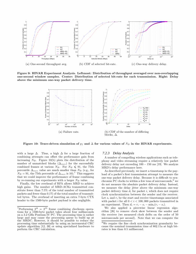
One cause for the high failure rate is the low number ofblock subdivisions in a frame in our implementation (NB =6). We post-processed the data trace of our experiments toanalyze how pf varies with other values for NB and plotthe results in Figure 10(a).6 The plot shows that pf dropsas NB increases, which is consistent with the analytic modelfor burst bit-error channels that we derived in Section 3. Forexample, pf drops from 80% to 60% when NB = 91 (i.e.,B = 16 bytes).
As discussed in Section 3, increasing NB can potentiallyincrease ∆, the number of differing blocks between twoframes. To avoid overloading the MRDC, we may need toabort the frame combining operations for frames received
6Recall that pf excludes those frames that are successfullydelivered by soft selection (Section 3.1). While the major-ity of frame combining attempts were performed for cor-rupt frames that were simultaneously received by the APs,a significant fraction of the frame combining attempts wereperformed with retransmitted frames. For simplicity, weexcluded the retransmitted frames in our post processinganalysis. Nonetheless, our results should remain represen-tative because the retransmitted frames should have an in-dependent bit error behavior similar to the simultaneouslyreceived frames.
0 5 10 15 20 25 30 350
0.1
0.2
0.3
0.4
0.5
0.6
0.7
0.8
0.9
1
Throughput (Mbps)
Fra
ctio
n of
1.0
sec
ond
sam
ples
R1R2MRD−R1MRD−R2
(a) One-second throughput avg.
6 9 12 18 24 36 48 540
0.1
0.2
0.3
0.4
0.5
0.6
0.7
0.8
0.9
1
Selected Bitrate (Mbps)
Fra
ctio
n of
Tra
nsm
itted
Fra
mes
R1R2MRD
(b) CDF of selected bit-rate.
10−4
10−3
10−2
10−1
100
0
0.1
0.2
0.3
0.4
0.5
0.6
0.7
0.8
0.9
1
Fra
ctio
n of
Pac
kets
Delay (s)
R1R2MRD−R1MRD−R2
(c) One-way delivery delay.
Figure 9: HIVAR Experiment Analysis. Leftmost: Distribution of throughput averaged over non-overlappingone-second window samples. Center: Distribution of selected bit-rate for each transmission. Right: Delayabove the minimum one-way packet delivery time.
100
101
102
103
104
105
0
0.1
0.2
0.3
0.4
0.5
0.6
0.7
0.8
0.9
1
Number of blocks
Fra
me
Com
bini
ng F
ailu
re R
ate
(a) Failure rate.
0 5 10 15 200
0.1
0.2
0.3
0.4
0.5
0.6
0.7
0.8
0.9
1
Delta
Fra
ctio
n of
Suc
cess
fully
Com
bine
d F
ram
es
NB=361
NB=181
NB=91
NB=46
NB=23
NB=12
NB=6
(b) CDF of the number of differingblocks, ∆.
Figure 10: Trace-driven simulation of pf and ∆ for various values of NB in the HIVAR experiments.
with a large ∆. Thus, a high ∆ for a large fraction ofcombining attempts can offset the performance gain fromincreasing NB . Figure 10(b) plots the distribution of thenumber of unmatched blocks (∆succ) for the successfullycombined frames at various NB . For NB 6 91, the 75thpercentile ∆succ value are much smaller than NB (e.g., forNB = 91, the 75th percentile of ∆succ is 10).7 This suggeststhat we could improve the performance of frame combiningby re-running our experiments with a larger NB value.
Finally, the low overhead of RFA allows MRD to achievehigh gains. The number of MRD-ACKs transmitted con-stitute fewer than 7.5% of the total number of transmittedpackets and fewer than 0.1% of the total number of transmit-ted bytes. The overhead of inserting an extra 7-byte CTXheader to the 1500-byte packet payload is also negligible.
7Performing 2∆ = 210 frame combining checksum opera-tions for a 1500-byte packet takes about four millisecondson a 3.2 GHz Pentium IV PC. The processing time is ratherlarge and may cause the processing queue to build up atthe MRDC. However, it should be possible to reduce theprocessing time substantially by using an incremental CRCupdate algorithm [12, 30] or using specialized hardware toperform the CRC calculation.
7.2.3 Delay AnalysisA number of compelling wireless applications such as tele-
phony and video streaming require a relatively low packetdelivery delay not exceeding 100− 150 ms [19]. We analyzeMRD’s delay performance here.
As described previously, we insert a timestamp in the pay-load of a packet’s first transmission attempt to measure theone-way packet delivery delay. Because it is difficult to syn-chronize PC clocks to within a few tens of microseconds,8 wedo not measure the absolute packet delivery delay. Instead,we measure the delay jitter above the minimum one-waypacket delivery time di for packet i, which does not requireclock synchronization between the sender and the receiver.Let si and ri be the start and receive timestamps associatedwith packet i for all 0 < i < 100, 000 packets transmitted inan experiment. Then di = ri − si −mini(ri − si).
We also applied a piecewise linear regression algo-rithm [26] to remove clock skew between the sender andthe receiver (we measured clock drifts on the order of 50microseconds per second). Note that we can compute the
8We require the fine clock synchronization granularity be-cause the nominal transmission time of 802.11a at high bit-rates is less than 0.5 millisecond.

one-way packet delivery delay by adding mini(ri−si), whichincludes the nominal transmission time and processing de-lay. In practice, this number is less than one millisecond. Wewill ignore this minor adjustment and use the terms “delayjitter” and “delay” interchangeably.
Figure 9(c) shows the one-way delay distribution for ourHIVAR experiments. The MRD median delay is below 1 msand has 25% more packets delivered than R1 and R2. Thelow median delay is due to its ability to maintain a highbit-rate throughout the experiments. However, about 35%of the packets in MRD were delivered with a significantlyhigher delay than R1 and R2. Nonetheless, MRD was ableto deliver 95% of the packets within a delay of 35 ms, whichis well below the delay bound of 150 ms that can be toleratedby telephony and video applications.
We attribute the increased packet delivery delay in MRDto the fact that there were a significant number of framesthat required retransmissions. In the design of the MRDC,we assumed an in-order packet delivery service and addeda re-order buffer at the MRDC (Section 4.3). Whenever aretransmission is required, the reorder buffer blocks subse-quent packets from being forwarded and increases the packetdelivery delay for all of them.
Another source of delay comes from the losses of MRD-ACKs on the reverse channel, which delays the trigger toretransmit a packet. Also, the user space implementation ofthe MRDC is inefficient as interrupts and user space buffer-ing can add delays in generating and sending MRD-ACKs.
7.3 LOVAR Experiments
R1
R214m
12m
3.5m
C
Figure 11: A diagram that illustrates the relativepositions of the transmitter C and the receivers R1and R2 in the LOVAR experiments.
We evaluate the performance of MRD in a scenario wherethe channel variability is low, using the setup depicted inFigure 11. The parameters and methods we use for the LO-VAR experiments are the same as the HIVAR experiments,except that we use a stationary desktop transmitter insteadof a mobile one. Also, our measurements for the LOVARexperiments were collected before we introduced our modi-fications to the MADWiFi autorate algorithm in Section 5.Thus, the autorate results presented in this section under-state the performance of the MRD system. Nevertheless,our results provide an interesting comparison of the systemoperating under different situations.
7.3.1 ThroughputFigure 12(a) shows the throughput averaged over five tri-
als for the LOVAR experiments. We ran different experi-ments using two different fixed bit-rates (36 and 48 Mbps)
Experiment FLR FRR FRRSS FRRF C
MRD-R1 0.359 0.895 0.694 0.200MRD-R2 0.354 0.958 0.819 0.139
Table 4: Frame loss and frame recovery rates of thelow channel variability experiments.
and using the standard rate adaptation algorithm (Auto)implemented in the MADWiFi WLAN driver. The fig-ure shows that the MRD schemes at fixed bit-rate of 48Mbps performed better than all other schemes. The dashedlines marks the maximum 802.11a UDP throughput for afixed bit-rate 36 and 48 Mbps links, which are 23 and 27Mbps respectively. The MRD throughput is between 94.4%and 96.6% of the maximum UDP throughput at 48 Mbps.Despite the overhead of transmitting MRD-ACK packets,MRD-R1 increases throughput over R1 by 54.6% at the fixedbit-rate of 48 Mbps, while MRD-R2 improves throughputover R2 by 20.2% at 48 Mbps. Similar to the HIVAR exper-iments, both MRD-R1 and MRD-R2 achieved very similarthroughput results, again suggesting that the performanceof MRD is relatively insensitive to the choice of active APin our experiments.
Under autorate (Auto), the throughput gains by MRD-R1 and MRD-R2 diminish to 3.7% and 8.1% respectively.The main reason for the diminished gains is that the LO-VAR MRD experiments used the unmodified version ofthe autorate algorithm. The algorithm ignores informa-tion from the MRD-ACK, so it adapts its bit-rate basedonly on the observed loss rate of the link-layer transmis-sions to the active AP. Consequently, the algorithm selectsa suboptimal bit-rate. For example, Figure 12(b) shows thatMRD-R2 (Auto) selected 36 Mbps roughly 70% of the timeeven though our fixed rate experiments shows that it couldachieve a high throughput at 48 Mbps.
We believe that the MRD throughput results would im-prove if we used the modified autorate algorithm for MRD inour LOVAR experiments. The potential throughput perfor-mance could be as high as (if not higher than) the 48 Mbpsfixed rate MRD experiments, which improved throughputby 9% to 16% over R1 Auto and R2 Auto.
Another reason for the diminished gain is the low variabil-ity of the channel. Although the frame loss rate was substan-tial at 48 Mbps, there was almost no loss at 36 Mbps. Thus,the throughput for R1 and R2 is lower bounded at the 36Mbps bit-rate and caps the maximum achievable throughputgain for MRD.
7.3.2 Source of ImprovementWe analyze the sources of improvement for the 48 Mbps
fixed bit-rate LOVAR experiments and summarized the re-sults in Table 4. The active APs in the LOVAR experimentsobserved similar frame loss rates to the ones observed in theHIVAR experiments, but the FLR is much higher. It rangedbetween 90%−96% for LOVAR compared to 50%−57% forHIVAR. There were also a larger number of frames recoveredby frame combining in the LOVAR experiments.
We found that the total number of frame combining at-tempts was proportionately similar to the HIVAR experi-ments. It represents 37% and 25% of the total number offrames that were not successfully received by the active APin MRD-R1 and MRD-R2. Thus, the increased number of

R1 R2 MRD−R1 MRD−R20
5
10
15
20
25
30G
oodp
ut (
Mbp
s)
36 Mbps48 MbpsAuto
(a) Throughput.
0 5 10 15 20 25 30 350
0.1
0.2
0.3
0.4
0.5
0.6
0.7
0.8
0.9
1
Throughput (Mbps)
Fra
ctio
n of
1.0
00 s
econ
d sa
mpl
es
R1 (48 Mbps)R2 (48 Mbps)MRD−R1 (48 Mbps)MRD−R2 (48 Mbps)R1 (Auto)R2 (Auto)MRD−R1 (Auto)MRD−R2 (Auto)
(b) One-second throughput avg.
10−4
10−3
10−2
10−1
100
101
0.55
0.6
0.65
0.7
0.75
0.8
0.85
0.9
0.95
1
Fra
ctio
n of
Pac
kets
Jitter (s)
R1 (48 Mbps)R2 (48 Mbps)MRD−R1 (48 Mbps)MRD−R2 (48 Mbps)R1 (Auto)R2 (Auto)MRD−R1 (Auto)MRD−R2 (Auto)
(c) One-way delivery delay.
Figure 12: LOVAR Experiment Analysis. Left: Throughput averaged over 5 trials. The dashed line marksthe maximum achievable UDP throughput (23 and 27 Mbps) for 802.11a fixed at 36 Mbps and 48 Mbps bit-rates. Center: Distribution of throughput averaged in non-overlapping one-second window samples. Right:Delay above the minimum one-way packet delivery time.
frame combining recoveries were due to a large reductionin frame combining failure rate. Indeed, the frame combin-ing failure rate pf was about 45% in both sub-experiments,which is a large drop from the 80% in the HIVAR experi-ments.
Like the HIVAR experiments, the average pf drops dra-matically if the frame were subdivided into smaller blocks.Our simulation shows that pf = 17% for NB = 91 (i.e.,B = 16 bytes). At the same time, ∆succ (defined in Sec-tion 7.2.2) remains low for the successfully combined frames:the 95th percentile of ∆succ for NB = 91 is 10.
7.3.3 Delay PerformanceWe repeat the delay analysis in Section 7.2.3 for the LO-
VAR experiments. Figure 12(c) shows the one-way delaydistribution for the fixed and autorate experiments. Com-pared to the HIVAR experiments, MRD delivered packetswith a lot smaller delay because it was able to recover al-most all corrupt frame transmissions to the active AP. As aresult, the LOVAR experiments required much fewer frameretransmissions than the HIVAR experiments. Our LOVARexperiments show that MRD delivered 99% of the success-fully received frames within 20 ms.
Finally, we observe a long tail in the one-way delaydistribution (but representing only a tiny fraction of thetransmitted packets) for the single radio communicationschemes that last up to several hundred milliseconds. Thistail is mostly an artifact of handling retransmissions inthe driver, where kernel interrupts can happen in betweenretransmissions. We suspect that the long tails arise frompackets that require a large number of retransmissionsbecause such packets may experience more interruptsfrom the kernel than packets delivered with fewer or noretransmissions. The MRD scheme does not have this longtail because it successfully delivers packet with a lot fewer(re)transmissions.
In summary, we found that MRD produced through-put gains in all experiments, regardless of the channelvariability experienced by the client. In our HIVARexperiments, we found that MRD was able to increase
throughput up to 2.3× that of the best AP when only asingle radio is used. In our LOVAR experiments, MRD, ata fixed bit-rate of 48 Mbps, the throughput improvement isless impressive but still significant, between 9% and 16%.
8. DISCUSSIONThe conventional wisdom of managing link quality in
WLANs is to have the clients adapt to the channel con-ditions (i.e., adapt the bit-rate) before changing to an alter-nate link (e.g., AP) with a better channel quality. MRD canbe viewed as taking the opposite approach, where the clientsuse multiple links simultaneously before changing their bit-rate to adapt to the underlying channel.
Our experimental results suggest that, with MRD, evena simple rate adaptation algorithm, such the one based-onMADWiFi, can perform well in different environments. Incontrast, we observed a rather large performance differencebetween the HIVAR and LOVAR experiments in the non-MRD schemes. We believe that the large performance differ-ence is attributed not only to the increased frame loss ratesobserved at the individual APs, but also to the sub-optimalbit-rates that might have been chosen by the MADWiFiautorate algorithm in the high channel variability environ-ment. (In Section 5, we tuned the algorithm to work wellwith multiple radios and frame combining, but did not alterthe fundamental mechanisms used in the algorithm.)
In fact, we can use the results from the previous section toshow that there is room for improvement in the rate adap-tation algorithm. Table 3 and Figure 9(b) show that theframe loss rate to the active AP in MRD-R1 was 35% andthat MRD-R1 selected a bit-rate of at least 24 Mbps over90% of the time. Multiplying 1−FLR with the the effectivethroughput of the 24 Mbps (17.8 Mbps) bit-rate yields 11.6Mbps. Thus, we could have fixed the bit-rate to 24 Mbps forthe non-MRD HIVAR experiment (R1) to improve the per-formance by 1.4× over the MADWiFi autorate algorithm,which achieved 8.25 Mbps. (Although the improvement issignificant, it is not as great as MRD-R1, which achieved a2.3× improvement at 18.7 Mbps.)
We are not suggesting that a fixed bit-rate should beused for non-MRD wireless links operating in a channel

with high variability: selecting an optimal fixed bit-rate forsuch a channel still requires an adaptive algorithm. Rather,our intent is to use the example to motivate the followingopen questions: 1) Could other existing autorate schemes(e.g., RBAR [15], AARF [20], MiSer [27], OAR [29], Sam-pleRate [10]) be used to improve performance of the non-MRD schemes in our HIVAR experiments? 2) Can we de-sign an autorate algorithm for a non-MRD WLAN thatperforms well under a variety of channel conditions in areal environment? These are open questions, but we havedemonstrated—using real-world experiments—that MRDcan use a simple rate adaptation algorithm to produce goodperformance under different and difficult channel conditions,and that with MRD, the need for a finely tuned rate ada-patation algorithm is not as important as with single-radioschemes.
As mentioned in Section 6, the MRDS needs to assumecontrol over all retransmissions. Performing software-basedretransmissions in the driver, however, also has the side ef-fect of disabling the exponential backoff controlled by thefirmware.
We acknowledge that the relative throughput improve-ment by MRD may be reduced when exponential backoff isenabled. That is because the link layer increases the back-off window whenever a client fails to successfully transmit adata frame to the target receiver (i.e., the active AP) at thelink layer. In our current design, the link layer is obliviousto MRD. Even if the data frame is recovered through softselection or block-based combining, the link layer may notreduce the contention window (which is what CSMA doeswhen the link-layer transmission succeeds). Consequently,the backoff window may increase unnecessarily and reduceMRD’s performance.
Conceivably, we can alleviate the problem by creating aninterface that allows MRD to inform the link-layer back-off mechanism about the results of frame recovery at theMRDC. Designing a medium access control algorithm thatcan adapt to MRD’s error recovery results is an interestingopen problem.
Despite the above caveat, MRD effectively reduces framelosses and the total number of transmissions required to de-liver a packet, without increasing the nominal frame trans-mission time as in other existing approaches like using low-ering data rates or employing forward error correction.
9. RELATED WORKThe idea of coordinating multiple radios in WLANs has
recently received considerable attention. The authors in [9]proposed to embed multiple radios on a single device forbetter energy and mobility management, capacity enhance-ment, and avoiding channel failures. A system that usesfine-grained path selection (FGPS) that switches transmis-sions from among a set of nearby APs was demonstrated toeffectively reduce path dependent losses in WLANs [24] andto improve the quality of video streaming applications [23].FGPS takes advantage of path diversity at the transmit sideof the system. MRD compliments FGPS to reap the benefitof path diversity at the receive side of the system.
Diversity reception is a common technique used to miti-gate the effects of fading, and interference in wireless sys-tems. Almost all WLAN devices have embedded morethan one antenna that gets selected based on packet lossrates. Recently, the IEEE incorporated a more advanced an-
tenna diversity technique Multiple-Input Multiple-Output(MIMO) [25] into the physical layer specifications of theirnext generation WLAN devices known as 802.11n [35]. Ingeneral, this class of techniques, known as microdiversity,are tightly integrated with the physical layer and mostlyhelp in mitigating path-dependent effect localized at one re-ceiver. In contrast, the MRD WLAN operates above thephysical layer and may be used to collect data frames re-ceived by radios distributed across different access pointsat different locations; thus, our system achieves diversity atthe macro level. Furthermore, a WLAN operator can builda MRD WLAN using 802.11n hardware to exploit the pathdiversity gains at different scales.
Code Division Multiple Access (CDMA) cellular phonenetworks have long used “macrodiversity” to improve per-formance and to provide seamless handoff between base sta-tions [28]. Both [21] and [33] applied the idea to use macro-diversity and frame combining on frames received from ad-jacent access points to improve uplink WLAN performancein the same way as MRD. However, [21] presents simulatedresults based on a capture model and ignores protocol levelissues such as ARQ. The contributions of [33] lie in the the-oretical performance evaluation in the context of a WLANbased on Bluetooth [11] radios. In contrast, our contribu-tions lie in the design of a macrodiversity system that workswell in CSMA-based WLANs and in conducting a perfor-mance study of a fully implemented receiver macrodiversitysystem on a real testbed.
The idea of recovering a frame by combining it with aretransmitted version was first proposed in [31] and thenfurther analyzed in [13, 14]. Hybrid ARQ is an extensionof this technique, which combines forward error correction(FEC) and retransmission to recover unsuccessful transmis-sions [22]. Although numerous hybrid ARQ schemes areavailable, we chose block-based combining because it hasthe advantage that 1) there is no encoding and it insertsno extra FEC bits into the frame, 2) it uses hard decision(i.e., it performs correction using only the received data bitswithout requiring extra information from the physical layer),and consequently 3) the algorithm is easy to implement. Ascheme proposed in [8] uses collaborative decoding to im-prove link reliability. The scheme is complex and requiresthe receivers to exchange soft decision estimates of each datasymbol, which is not accessible from any wireless device onmarket today.
A proposal that uses 802.11’s request-to-send(RTS)/clear-to-send(CTS) control packets to convey the results of packetcombining is outlined in [13]. Because RTS/CTS is requiredfor every transmission, the proposed method (which wasnot implemented and experimentally evaluated) will pro-duce much higher overhead than our RFA protocol.
Like MRD, multi-user diversity [18] and medium-accessdiversity [17] also exploit the fact that losses at different re-ceivers occur independently. In both techniques, an AP hasa queue of packets destined for different clients and attemptsto improve network performance by scheduling transmis-sions to the client receiver that has the best channel condi-tion in a given moment. In contrast to MRD, the techniquerequires explicit receiver selection and channel quality feed-back from each receiver. These requirements are necessaryif the receivers are not inter-connected by a high bandwidthback-channel that MRD relies upon.

10. CONCLUSIONMRD uses wireless path diversity to improve loss resilience
in wireless local area networks. It coordinates wireless re-ceptions among multiple radios—either co-located on thesame device or distributed across different access points inthe WLAN infrastructure—to increase loss resilience againstpath-dependent corruptions in the wireless medium. Usingmultiple radios, MRD performs frame combining, which at-tempts to correct bit errors by combining corrupt copies ofdata frames received by each radio in our system. Becauselosses are often independent among different receivers, MRDis able to achieve significant improvement in loss rates.
Our experiments in an in-building testbed using commod-ity PCs and 802.11a/b/g wireless interfaces demonstratethroughput gains of up to 2.3× that of single radio com-munication schemes, with the corresponding one-way delaybounded to 35 ms for 95% of the delivered packets.
From the experience we gathered in building and evalu-ating MRD, we discovered a number of performance opti-mizations such as marking packets for low-latency and out-of-order delivery, and sharing MRD feedback with the link-layer to improve rate adaptation and contention window ad-justments. We plan to pursue to design and integrate theseoptimizations to further improve the performance of MRDin the future.
11. ACKNOWLEDGMENTSWe thank our shepherd Rajive Bagrodia for his useful
suggestions in the revision of this paper. We also thankGodfrey Tan, Srikanth Kandula, Eugene Shih, John Bicket,Vladimir Bychkovsky and the anonymous reviewers for theirinsightful comments, and Michel Goraczko for his technicalassistance.
This material is based upon work supported by the Na-tional Science Foundation under Grant No. 0205445. Theviews expressed in this paper are not necessarily those ofthe National Science Foundation.
12. REFERENCES[1] Madwifi: Multiband Atheros Driver for WiFi.
http://madwifi.sourceforge.net/.
[2] tcpdump/libpcap. http://www.tcpdump.org.
[3] Engim product overview. http://www.engim.com/products.html,2003.
[4] IEEE P802.11i/D10.0. Medium Access Control (MAC) SecurityEnhancements, Apr. 2004.
[5] Madwifi mailing list archive.http://news.gmane.org/gmane.linux.drivers.madwifi.devel,Feb. 2005.
[6] IEEE 802.11b/d3.0 Wireless LAN Medium Access Control(MAC) and Physical Layer (PHY) Specification, Aug. 1999.
[7] IEEE Standards for Local and Metropolitan Area Networks:Standard for Port Based Network Access Control, Oct. 2001.
[8] Avudainayagam, A., Shea, J., Wong, T., and Li, X. Reliabilityexchange schemes for iterative packet combining in distributedarrays. In Proc. of IEEE WCNC (New Orleans, LA, Mar.2003), pp. 832–837.
[9] Bahl, P., Adya, A., Padhye, J., and Wolman, A. Reconsideringwireless systems with multiple radios. ACM CCR (Oct. 2004),39–46.
[10] Bicket, J. C. Bit-rate selection in wireless networks. Master’sthesis, Massachusetts Intitute of Technology, Cambridge, MA,Feb. 2005.
[11] Specification of the bluetooth system.http://www.bluetooth.com/, Dec. 1999. Bluetooth SpecialInterest Group document.
[12] Braun, F., and Waldvogel, M. Fast incremental CRC updatesfor IP over ATM networks. In Proc. of IEEE HPSR (Dallas,TX, May 2001).
[13] Chakraborty, S., Yli-Juuti, E., and Liinaharja, M. An ARQscheme with packet combining. IEEE Communications Letters2, 7 (July 1998), 200–202.
[14] Daraiseh, A.-G. A., and Baum, C. W. Methods for packetcombining in HARQ systems over bursty channels. MobileNetworks and Applications 2 (Oct. 1997), 213–224.
[15] Holland, G., Vaidya, N. H., and Bahl, P. A rate-adaptiveMAC protocol for multi-hop wireless networks. In Proc. ofACM MobiCom (Rome, Italy, July 2001), pp. 236–251.
[16] IEEE 802.11 Working Group. Draft Supplement toInternational Standard for Information Exchange betweensystems - LAN/MAN Specific Requirements, Nov. 2001.
[17] Ji, Z., Yang, Y., Zhou, J., Takai, M., and Bagrodia, R.
Exploiting medium access diversity in rate adaptive wirelessLANs. In Proc. of ACM MobiCom (Philadelphia, PA, Sept.2004), pp. 345–359.
[18] Knopp, R., and Humblet, P. A. Information capacity and powercontrol in single-cell multiuser communications. In Proc. ofIEEE ICC (Seattle, WA, June 1995), pp. 331–335.
[19] Kopsel, A., and Wolisz, A. Voice transmission in an IEEE802.11 WLAN based access network. In Proc. of ACMWoWMoM (Rome, Italy, July 2001), pp. 23–32.
[20] Lacage, M., Manshaei, M. H., and Turietti, T. IEEE 802.11rate adaptation: A practical approach. In Proc. of ACMMSWiM (Venezia, Italy, Oct. 2004), pp. 126–134.
[21] Leung, V. C. M., and Au, A. W. Y. A wireless local areanetwork employing distributed radio bridges. WirelessNetworks 2 (1996), 97–107.
[22] Lin, S., Costello, D., and Miller, M.
Automatic-repeat-request error-control schemes. IEEECommunications Magazine 22, 12 (Dec. 1984), 5–17.
[23] Miu, A., Apostolopoulos, J., Tan, W. T., and Trott, M.
Low-latency wireless video over 802.11 networks using pathdiversity. In Proc. of IEEE ICME (Baltimore, MD, July 2003),vol. 2, pp. 441–444.
[24] Miu, A. K., Tan, G., Balakrishnan, H., and Apostolopoulos, J.
Divert: Fine-grained path selection for wireless LANs. In Proc.of ACM MobiSys (Boston, MA, June 2004), pp. 203–216.
[25] Molisch, A. F., and Win, M. Z. MIMO systems with antennaselection. IEEE Microwave Magazine (Mar. 2004), 46–56.
[26] Moon, S. B., Skelly, P., and Towsley, D. Estimation andremoval of clock skew from network delay measurements. InProc. of IEEE INFOCOM (New York, NY, Mar. 1999), vol. 1,pp. 227–234.
[27] Qiao, D., and Choi, S. Goodput enhancement of IEEE 802.11awireless LAN via link adaptation. In Proc. of IEEE ICC(Helsinki, Finland, June 2001), pp. 161–175.
[28] Rappaport, T. Wireless Communications. Prentice Hall,Upper Saddle River, N.J., 1996.
[29] Sadeghi, B., Kanodia, V., Sabharwal, A., and Knightly, E.
Opportunistic media access for multirate ad hoc networks. InProc. of ACM MobiCom (Atlanta, GA, Sept. 2002), pp. 24–35.
[30] Satran, J., Sheinwald, D., and Shimony, I. Out of orderincremental CRC computation. To appear: IEEE Trans. onComputers, 2005.http://www.haifa.il.ibm.com/satran/ips/crc_23feb2003.pdf.
[31] Sindhu, P. Retransmission error control with memory. IEEETrans. on Communications 25 (May 1977), 473–479.
[32] Stevens, R. W. TCP/IP Illustrated. Addison-Wesley, Reading,MA, 1994.
[33] Valenti, M. C. Improving uplink performance bymacrodiversity combining packets from adjacent access points.In Proc. of IEEE WCNC (New Orleans, LA, Mar. 2003),pp. 636–641.
[34] Willig, A., Kubisch, M., Hoene, C., and Wolisz, A.
Measurements of a wireless link in an industrial environmentusing an IEEE 802.11-compliant physical layer. IEEE Trans.on Industrial Electronics 43 (Dec. 2002), 1265–1282.
[35] Wilson, J. M. The next generation of wireless LAN emergeswith 802.11n. Device Forge, Aug. 2004.http://www.deviceforge.com/articles/AT5096801417.html.