improving safety and efficiency of agvs at warehouse...
TRANSCRIPT

Improving Safety and Efficiency of AGVsat Warehouse Black Spots
Markus BoehningSICK AG Applied Research22143 Hamburg, Germany
E-mail: [email protected]
Abstract—In order to achieve safe operation of automatedguided vehicles (AGVs) at warehouse black spots such as inter-sections, AGVs decelerate before reaching them. Having crossedthe black spot, they reaccelerate back to full speed. Most of thetime, the black spot is void of other vehicles or workers, so thisprogrammed behavior is unnecessary and thus very inefficient.To overcome this inefficiency, the black spot can be monitored byan infrastructure-based environment perception system consistingof one or several laser scanners in combination with a dataprocessing electronic control unit (ECU). The presence of objectsin the black spot is communicated to approaching AGVs via acontrol center, allowing the AGV to pass the black spot at fullspeed if there are no other objects present and only deceleratingif there are other objects present.
I. INTRODUCTION
AGVs are increasingly used to efficiently and safely movematerials and goods around in industrial environments such asa manufacturing facility or a warehouse. In order to achieveand ensure accident free operation, especially regarding humanworkers, they are most commonly equipped with a set ofsafety laser scanners. These safety laser scanners monitor theenvironment around the AGV in a plane parallel to and slightlyabove the ground with overlapping fields of view, as illustratedin Fig. 1, and thus provide a 360◦ view around the AGV.
However, at black spots such as intersections where objectsare not detectable by the safety laser scanners due to theoccluded field of view, special care has to be taken. Currently,two measures are in place to also ensure safety in these kindsof situations. Firstly, a hemispherical mirror is mounted abovethe intersection so that approaching workers can look forapproaching AGVs, as shown in Fig. 2.
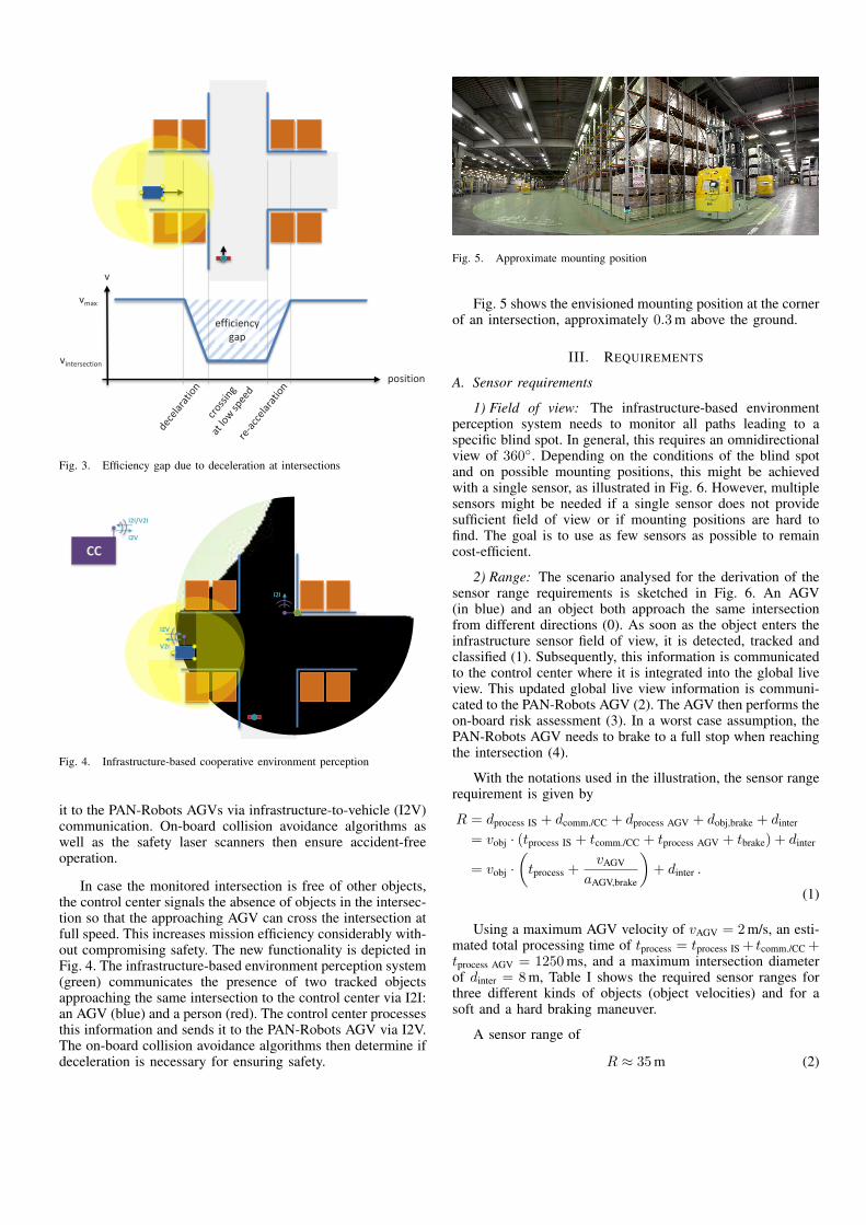
Secondly, AGVs are programmed to decelerate to half theirnominal velocity when approaching intersections, traversingthem at this reduced velocity and to reaccelerate when leavingthe intersection in order to significantly reduce the brakingdistance in case of workers suddenly appearing in the laserscanner’s safety areas, as illustrated in Fig. 3. This proce-dure significantly reduces the overall efficiency in terms ofincreased mission time, energy consumption and mechanicalwear on the AGV and is unnecessary in situations where theintersection is free of workers, other vehicles or obstacles.
The vision of the research project ’Plug and NavigateRobots for Smart Factories (PAN-Robots)’ funded by theEuropean Commision in the 7th Framework Programme is ahighly automated logistics system supporting future factoriesto achieve maximum flexibility, cost and energy efficiency as
Fig. 1. AGV (blue) with overlapping scan areas from three safety laserscanners
Fig. 2. Hemispherical mirror mounted above an intersection
well as accicent-free operation. One of the many technicalobjectives is to address the outlined lack of efficiency andto enhance safety and efficiency at warehouse black spots.The following sections present the PAN-Robots concept ofan infrastructure-based environment perception system, itstechnical requirements and the system architecture [1], [2],[3].
II. CONCEPT
The PAN-Robots concept to reduce the above mentionedefficiency gap is an infrastructure-based cooperative environ-ment perception system. Its objective is to provide the infor-mation about the presence or absence of objects near the moni-tored intersection to each approaching PAN-Robots AGV. Thisinfrastructure system detects, tracks and classifies all objectsin the vicinity of the monitored area and communicates thisinformation to the control center via wireless infrastructure-to-infrastructure (I2I) communication. The control center inturn integrates and consolidates this information disseminates
vmax
vintersection
v
position
efficiency gap
Fig. 3. Efficiency gap due to deceleration at intersections
CC
I2V
V2I
I2I/V2I
I2V
I2I
Fig. 4. Infrastructure-based cooperative environment perception
it to the PAN-Robots AGVs via infrastructure-to-vehicle (I2V)communication. On-board collision avoidance algorithms aswell as the safety laser scanners then ensure accident-freeoperation.
In case the monitored intersection is free of other objects,the control center signals the absence of objects in the intersec-tion so that the approaching AGV can cross the intersection atfull speed. This increases mission efficiency considerably with-out compromising safety. The new functionality is depicted inFig. 4. The infrastructure-based environment perception system(green) communicates the presence of two tracked objectsapproaching the same intersection to the control center via I2I:an AGV (blue) and a person (red). The control center processesthis information and sends it to the PAN-Robots AGV via I2V.The on-board collision avoidance algorithms then determine ifdeceleration is necessary for ensuring safety.
Fig. 5. Approximate mounting position
Fig. 5 shows the envisioned mounting position at the cornerof an intersection, approximately 0.3 m above the ground.
III. REQUIREMENTS
A. Sensor requirements
1) Field of view: The infrastructure-based environmentperception system needs to monitor all paths leading to aspecific blind spot. In general, this requires an omnidirectionalview of 360◦. Depending on the conditions of the blind spotand on possible mounting positions, this might be achievedwith a single sensor, as illustrated in Fig. 6. However, multiplesensors might be needed if a single sensor does not providesufficient field of view or if mounting positions are hard tofind. The goal is to use as few sensors as possible to remaincost-efficient.
2) Range: The scenario analysed for the derivation of thesensor range requirements is sketched in Fig. 6. An AGV(in blue) and an object both approach the same intersectionfrom different directions (0). As soon as the object enters theinfrastructure sensor field of view, it is detected, tracked andclassified (1). Subsequently, this information is communicatedto the control center where it is integrated into the global liveview. This updated global live view information is communi-cated to the PAN-Robots AGV (2). The AGV then performs theon-board risk assessment (3). In a worst case assumption, thePAN-Robots AGV needs to brake to a full stop when reachingthe intersection (4).
With the notations used in the illustration, the sensor rangerequirement is given by
R = dprocess IS + dcomm./CC + dprocess AGV + dobj,brake + dinter
= vobj · (tprocess IS + tcomm./CC + tprocess AGV + tbrake) + dinter
= vobj ·(tprocess +
vAGV
aAGV,brake
)+ dinter .
(1)
Using a maximum AGV velocity of vAGV = 2 m/s, an esti-mated total processing time of tprocess = tprocess IS + tcomm./CC +tprocess AGV = 1250 ms, and a maximum intersection diameterof dinter = 8 m, Table I shows the required sensor ranges forthree different kinds of objects (object velocities) and for asoft and a hard braking maneuver.
A sensor range of
R ≈ 35 m (2)

CC
0
0
𝑑comm./CC
𝑑co
mm
./C
C
𝑑brake
𝑣AGV
𝑣o
bj
𝑑p
roce
ss IS
𝑑process IS
2 3
2
4
𝑅
4
3
𝑑o
bj,
bra
ke
𝑑in
ter
1
1
𝑑p
roce
ss A
GV
𝑑process AGV
Fig. 6. Worst-case scenario for the estimation of range requirements
TABLE I. SENSOR RANGE REQUIREMENTS FOR DIFFERENT OBJECTVELOCITIES AND BRAKING DECELERATIONS
AGV braking deceleration aAGV,brake
1.0m/s2
(hard braking)0.5m/s2
(soft braking)
obje
ctve
loci
tyv
obj
0.8m/s(walking person)
10.6m 12.2m
2m/s(running person)
14.5m 18.5m
5m/s(forklift)
24.3m 34.3m
allows for AGV soft braking even for forklifts, the fastest ob-jects expected in a warehouse environment. For hard braking,a sensor range of R ≈ 25 m is sufficient. Since soft braking ispreferred, the higher range requirements are aimed for.
3) Angular resolution: For robust object detection, severalscan points per object are required. In order to detect an objectof width w at the maximum sensor range R with at least Nscan points, the angular resolution needs to be
∆α = arctan
(w
(N − 1) ·R
). (3)
With the above range requirement for soft braking of R =35 m, assuming an object width of w = 1 m and requiringN = 3 scan points on the object at that distance, the angularresolution needs to be
∆α ≈ 0.8◦. (4)
Accordingly, with the lesser range requirement for hard brak-ing of R = 25 m and the identical assumptions, the angularresolution needs to be ∆α ≈ 1.2◦.
4) Data acquisition rate: In order to cope with the possiblyhighly dynamic situations at intersections and other blind spots(manual forklifts can have a maximum velocity of 5 m/s andextremely high turning rates of more than 100 deg/s), the dataacquisition rate should be at least 10 Hz. This is particularly thecase if object velocities are calculated based on differentiation.
B. Data processing requirements
1) Object tracking: Each detected object needs to betracked with respect to the following properties:
• Timestamp: time of object detection with respect tothe global time frame, accuracy 5 ms with respect toglobal time reference,
• ID: a locally unique identification number duringobject lifetime,
• Position: estimated location of the object with re-spect to the local sensor coordinate system, accuracy:±0.1 m at 1σ,
• Size: the estimated size of the object in terms of widthand length, accuracy: ±0.1 m at 1σ,
• Velocity: the estimated velocity of the object (scalarvalue), accuracy ±0.5 m/s at 1σ,
• Heading: the estimated direction of motion with re-spect to the local sensor coordinate system, accuracy±15◦ at 1σ,
• Age: number of successive scans an object has beentracked,
• Hidden status: indicates whether the track has beenassociated with a measurement in the current scan orif it is just an prediction based on previous detections.
All estimated values should be supplemented by respectiveconfidence values indicating their estimation quality. It isimportant to detect the merging and splitting of tracks as itis a common reason for the appearance and disappearance ofghost tracks, respectively.
2) Object classification: The recognized objects need to beclassified as one of the following:
• Pedestrian
• AGV
• Manual forklift
• Electric tricycle
• Other dynamic object
• Static object
The class should be supplemented by a classification qualityindicating the confidence in the classification decision. Therate of correct classifications should exceed 90 %.
C. Communication requirements
1) Real-time data distribution: The fast processing anddelivery of information is just as important as the informationitself. So during the design and implementation, issues regard-ing data availability should be of the highest priority. As aresult, all the information provided to the perception modulesshould be transmitted with the lowest latency possible. Withthe term real-time it is assumed that the delay in informationdistribution is acceptable as long as it stays below a timingthreshold which is defined by the application requirements andthe algorithms capabilities.

Object detection
Object tracking
Object classification
𝑡comm. IS → CC
𝑡detect 𝑡track 𝑡classify
Data transmission
Object fusion
Data transmission
𝑡process IS 𝑡comm. CC → AGV
𝑡process
𝑡process CC
Risk assessment
Brake trigger
Emergency braking
𝑡brake 𝑡risk assessm. 𝑡trigger
𝑡process AGV
𝑡comm./CC
Fig. 7. Collision avoidance by infrastructure-based environment perceptionsystems
TABLE II. TIMING REQUIREMENTS FOR THEINFRASTRUCTURE-BASED ENVIRONMENT PERCEPTION SYSTEM
Parameter Minimum Aimed Remarks
tdetect 100ms(10Hz)
50ms(20Hz)
worst case: detection at end ofscan cycle
ttrack 300ms 150ms ≥ 3 detections required fortracking
tclassify 200ms 100ms +2 detections for reliableclassification
ttransmit IS→CC 50ms 50ms WLAN transmission time
tprocess CC 150ms 100ms object fusion
ttransmit CC→AGV 50ms 50ms WLAN transmission time
trisk assessment 300ms 150ms decision about emergency braking
ttrigger 100ms 50ms triggering the emergency braking∑1250ms 700ms
2) Transmission delay: On the one hand, the transmissiondelay from the infrastructure environment perception systemto the control center should be as low as possible for real-timesituation analysis and collision avoidance. On the other hand,established communication equipment should be used to keepcosts low. As a reasonable compromise, the transmission delayshould not exceed 50 ms.
3) Update rate: The data transmission from the infrastruc-ture installation to the control center should be in line with thesensor data acquisition rate of 10 Hz.
In order to support collision avoidance by theinfrastructure-based environment perception system, thechain of events additionally involves the data transmissionfrom the infrastructure systems to the control center, theprocessing of the data inside the control center and thetransmission of relevant data to AGVs nearby, as shown inFig. 7.
The range requirements above were calculated using a totalprocessing time of
tprocess = tprocess IS + tcomm./CC + tprocess AGV = 1250 ms (5)
and for a braking time of tbrake = 2000 ms at maximum AGVvelocity of vAGV = 2 m/s for hard braking (tbrake = 4000 msfor soft braking). The timing requirements for the individualcontributions to the total processing time are given in Table II.
IV. SPECIFICATION AND ARCHITECTURE
A. System architecture
The infrastructure-based cooperative environment percep-tion system has a layered architecture as illustrated in Fig. 8.On the sensor layer, a laser scanner provides raw scan data
WLA
N C
LIEN
T SE
NSO
RS
INFR
AST
RU
CTU
RE
ECU
PER
CEP
TIO
N
SEN
SIN
G
CO
MM
.
dyn
. ob
ject
s
Plug-In PICE-3500M
SICK LMS100
tim
e re
fere
nce
Eth
stat
ic 3
D m
ap
object tracking and classification
background elimination
pre-processing
Control Center
I2I communication
WLA
N
low-level fusion
Siemens SCALANCE W746-1PRO
Eth
scan
dat
a
Laserscanner
Fig. 8. The layered architecture and the data flow (left) as well asthe hardware components and the corresponding interfaces (right) of theinfrastructure-based environment perception subsystem
Fig. 9. Connection diagram of the infrastructure-based environment percep-tion system
of the monitored blind spot to the ECU. On the perceptionlayer, this ECU is responsible for pre-processing and times-tamping of raw measurements, low-level sensor data fusion,background elimination, object tracking, and classification.It thus transforms the raw laser scanner measurements intotracked and classified dynamic objects. These dynamic objectsare then transmitted to the control center via a wireless I2Icommunication unit to the control center for global live viewintegration via the communication layer.
Fig. 9 shows the deployed components in a connectiondiagram.
B. Hardware components specification
1) Laser scanner: The laser scanner to be deployed inthe infrastructure-based environment perception system is aSICK LMS100, as shown in Fig. 10. It is a small, lightand economical measurement system that provides real-timemeasurement data output via Ethernet interface. It offers a highangular resolution and high update rate. The LMS100 laserscanner will be mounted near the monitored blind spot so thatits scan plane is parallel to and approximately 0.3 m abovethe ground in order to support advanced pedestrian detection

Fig. 10. SICK LMS100 laser scanner
Fig. 11. Front (left) and back (right) panel of a PICE-3500M ECU
algorithms based on leg pendulum analysis, as illustrated inFig. 5.
2) Infrastructure ECU: The recording and processing ofthe 3D mapping task will be performed on an ECU. A generalpurpose industrial compact embedded fanless system is thePLUG-IN PICE-3500M, which is de-picted in Fig. 11. Theoperating system of the ECU will be a customized Linuxoperating system that runs in the RAM disk and is thereforepower failure safe. An NTP daemon supports precise timesynchronization with the global time reference provided bythe control center.
3) WLAN client: The proposed WLAN client is a SiemensSCALANCE W746-1PRO, as depicted in Fig. 12.
C. Software modules specification
1) Pre-processing: The pre-processing module carries outrange validation, coordinate transformation and timestampassociation on the raw laser scanner measurement data. Thesetasks are carried out for each deployed laser scanner.
2) Low-level fusion: If more than one laser scanner isused for infrastructure-based environment perception, the low-level fusion module merges the measurement data from theindividual laser scanners into a coherent set of measurements,taking the different mounting positions and time differencesinto account.
3) Background elimination: Using the static 3D map pro-vided by the control center, the static background of themonitored scene is eliminated, thus leaving only measurementsof dynamic objects.
Fig. 12. Siemens SCALANCE W746-1PRO WLAN client
4) Object tracking and classification: This module carriesout suitable data segmentation and relies on object contourmodels for object detection. It determines the position andsize of each detected object. Each new object is assigned a(locally) unique object ID. The object tracking module tracksthe positions of all detected objects in subsequent measurementupdates over time based on Kalman filtering. After a shorttime, the objects velocity and heading are determined, allowinga limited prediction of object motion. Based on the trackedfeatures, the object classification module will classify eachobject.
V. CONCLUSION
The presented PAN-Robots approach promises significantlyincreased safety and mission efficiency for AGVs at blackspots in warehouse operating environments.
ACKNOWLEDGMENT
PAN-Robots is funded by the European Commission underthe 7th Framework Programme Grant Agreement no. 314193.The partners of the consortium thank the European Commis-sion for supporting the work of this project.
REFERENCES
[1] PAN-Robots – Plug And Navigate Robots for Smart Factories: TechnicalAnnex, 2012.
[2] PAN-Robots – Plug And Navigate Robots for Smart Factories: UserNeeds and Requirements, 2013.
[3] PAN-Robots – Plug And Navigate Robots for Smart Factories: Specifi-cation and Architecture, 2013.