improving the quality of measurements through the ... · purposes including inspection and reverse...
TRANSCRIPT
Improving the Quality of Measurements through the Implementation of Customised Reference Artefacts
Andy ROBINSON*a, Michael MCCARTHYa, Stephen BROWNa, Anthony EVENDENa, Lifong ZOUb
aNational Physical Laboratory, Teddington, Middlesex, UK; bBarts & The London School of Medicine and Dentistry, Queen Mary University of London, UK
Abstract Three–dimensional (3D) optical scanning technology has made great advances over the last decade and the range of applications is continually growing. However, performance of scanning systems and the quality of measurement data can vary greatly with application. This paper discusses the need for customised reference artefacts and describes three calibrated freeform artefacts, developed at the National Physical Laboratory (NPL) – one related to generic freeform shapes, one related to body scanning, and another relating to dental scanning. The design, manufacture, calibration and implementation of these artefacts are discussed, together with examples of how they are used to add value to a measurement process. Keywords: Measurement, Standards, Reference artefact, Freeform, Metrology.
1. Introduction Significant advances have been made in 3D optical scanning technology in the last decade, and their impact is evident in the areas of aviation, automobile, medicine and dentistry. Measurements of subjects ranging from designed industrial components to human body parts, are made for a variety of purposes including inspection and reverse engineering, Flexibility, portability, speed of data capture, cost of system, and ease of use, are all reasons that make 3D scanning technology an increasingly attractive option. Currently however, very little exists in the way of documented verification standards for this technology. Standards that do exist are typically based around simple tests incorporating geometric objects. Furthermore, the performance of scanning systems is very dependent on the application. With scanning systems, many factors influence the quality of the measurements. For example, the setup of the scanning system, the object to be scanned and the measurement environment can have a profound impact on the scan quality. Whether scanning at the micrometre level or at the millimetre level, it is essential to have confidence in the quality of the measurements, in order that good decisions can be made based on the resulting data. Freeform surfaces, common in body scanning, often raise challenging problems both in terms of data capture and subsequent data analysis. This paper discusses the use of customised reference artefacts designed and developed using established metrological principles, as a way of selecting the right measurement strategy for a given application and to optimise the process to give the best possible results. The closer an artefact can replicate the intended application, in terms of surface finish, size, form and complexity, the more knowledge and confidence the user will gain with regard to the scanner’s likely performance. Three freeform artefacts and their applications are described – one related to generic freeform shapes, one related to body scanning, and one relating to dental scanning. The design, manufacture, calibration and implementation of these artefacts will be discussed, together with examples of how they are used to add value to a measurement process.
2. Challenges in Freeform measurements Freeform measurements prevalent in body scanning can present some of the most challenging and varied measurement subjects for 3D scanning systems. Fig. 1 shows a number of parts scanned at NPL. *[email protected]
3rd International Conference on 3D Body Scanning Technologies, Lugano, Switzerland, 16-17 October 2012
235

Fig. 1. A selection of parts scanned at NPL, (From top left, clockwise; small figurine (Homer); Minke whale bone; dental mould; ear model).
There are a number of factors, discussed below, which can affect measurement quality. Some factors are well documented industry-wide issues and others will depend on the particular optimisation of a scanning system. Consequently, often it is not until measurements are made, that problems are identified and frequently there is not an objective way to determine the quality of the captured data. The complexity of the shape can often mean that scan data is collected from a non-optimal scanning position or angle. Line of sight issues can restrict data capture from certain parts of the object [1, 2]. Multiple reflections from adjacent surfaces can produce false data. Certain features, such as edges, can be difficult to resolve because of measurement point spacing. Material and surface finish can have a very significant effect on the ability of a scanning system to capture data and on the quality of the captured data. Different colours or surface textures, such as skin or bone, can influence data quality [3]. Other materials, such as fabric, may have direction dependant properties. Ambient light conditions can also adversely affect scan quality [4]. Fig. 2 shows how colour can influence scan quality. In this case the scanning system has been unable to capture data from the darker surfaces.
Fig. 2. GretagMacbeth Colour Checker chart (left) and scan (right). Freeform surfaces can also present difficulties in the subsequent data processing steps undertaken in the post-processing software packages. Freeform objects can be very difficult to align because of the lack of geometric datum features. An example is the case of dental scanning when trying to align two scans (taken at different times) into the same coordinate system to investigation tooth wear. The choice of measurement surfaces can have a profound effect on a best-fit alignment process. Identifying and measuring features of interest can also be challenging.
3rd International Conference on 3D Body Scanning Technologies, Lugano, Switzerland, 16-17 October 2012
236

3. The need for measurement standards
3.1. Existing standards Traditional coordinate measuring machines (CMMs) typically consist of a tactile probe attached to the end of a head whose xyz coordinates are monitored. As the probe contacts the surface of a work piece being measured, the xyz co-ordinates are recorded. Since 1994, ISO 10360 series, ‘General Product Specifications (GPS) - Acceptance and re-verification tests for coordinate measuring machines (CMM)’ has been available to assist in verifying the performance of such machines. No such standard exists for 3D optical scanning systems. In 2002, a German guideline, VDI/VDE 2634, was introduced, relating to optically-based 3D scanning systems [5-8]. It currently consists of three parts:
• Part 1: –“Imaging systems with point-by-point probing”; • Part 2: –“Optical systems based on area scanning”; • Part 3: –“Multiple view systems based on area scanning”.
This VDI/VDE guideline defines a series of tests based on geometric measurements including spheres, planes and sphere spacings. While of some value, the tests do not incorporate many of the challenges relating to the measurement of freeform surfaces. In recent years a number of artefacts that have been produced in an attempt to address these challenges [9-14]. However, as yet there is nothing approaching a formal set of standards or procedures that apply to this technical area.
3.2. Why standards are important There are a number of industrial needs that could be met by the use of measurement standards, and in particular the realisation of the standards via a calibrated reference artefact. The needs include:
• An objective instrument selection process; • A method for evaluation of system performance or system verification; • An increase in confidence in measurement results; • An easier method of system optimisation.
As described earlier in the paper, system performance can vary enormously from application to application. This can make the selection and procurement process a particularly challenging one, especially when there is no consistent way to benchmark competing systems. A calibrated measurement artefact would enable an objective evaluation to be made and allow comparisons between competing systems. A calibrated reference artefact is an important tool in the evaluation of system performance. This evaluation can be extended to include testing under similar conditions, such as temperature or ambient lighting that are expected during the intended measurement process. Measurement of a calibrated artefact can help to determine the cause and scale of the errors and uncertainties associated with a 3D scanning system. The level of confidence in the measurement result will determine the usefulness of the data and the quality of the decisions based on the data. Measurement processes can often involve many parameters in the measurement of complex form. A calibrated reference artefact can be a useful tool in optimising the measurement strategy and influencing factors, such as laser intensity, exposure times, or scan angles.
4. Reference artefacts for freeform measurements The approach adopted by NPL, was to produce customised reference artefacts. By nature of the many applications of 3D scanning technology, it is very difficult for a single measurement standard to meet such a variety of needs. A customised artefact should closely replicate the intended application, including the parameters of interest, whether surface finish, form or feature. The artefact should be produced in a controlled manner and then calibrated to provide reference measurement data to enable a 3D scanning system to be compared. The calibration method should have a better uncertainty (by a factor of at least 5) than the anticipated uncertainty of the intended 3D scanning system.
3rd International Conference on 3D Body Scanning Technologies, Lugano, Switzerland, 16-17 October 2012
237
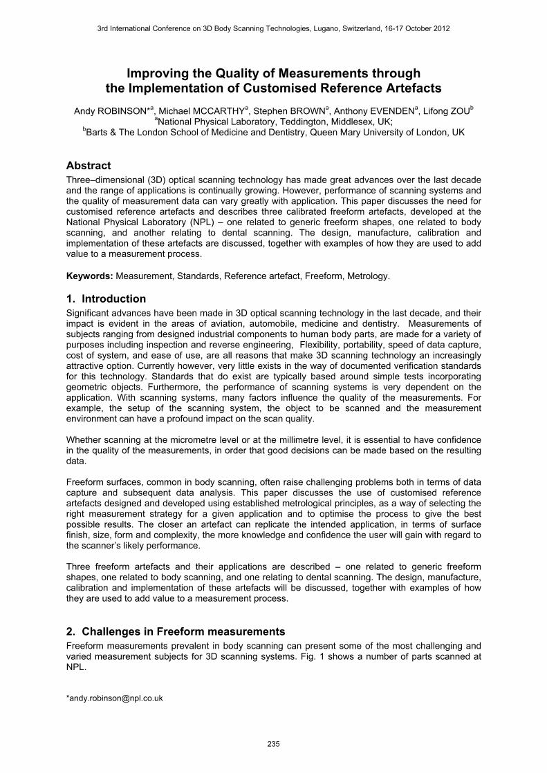
4.1. The NPL freeform artefact
Fig. 3. The NPL freeform artefact.
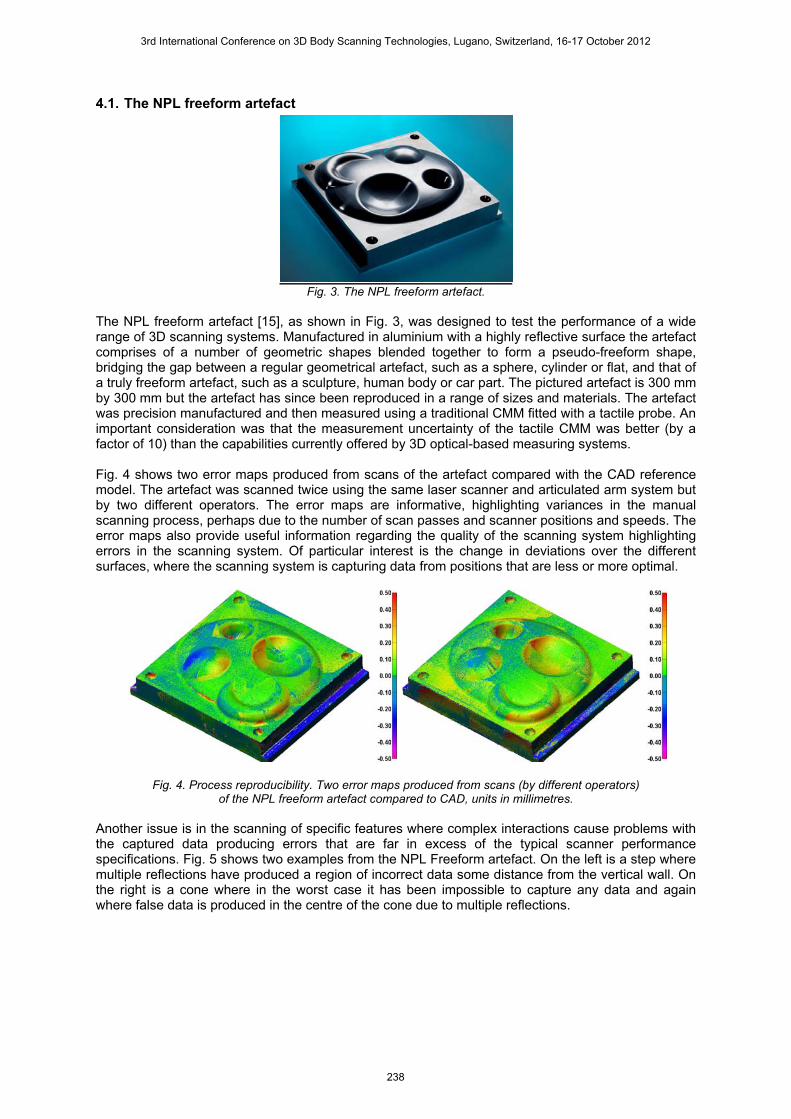
The NPL freeform artefact [15], as shown in Fig. 3, was designed to test the performance of a wide range of 3D scanning systems. Manufactured in aluminium with a highly reflective surface the artefact comprises of a number of geometric shapes blended together to form a pseudo-freeform shape, bridging the gap between a regular geometrical artefact, such as a sphere, cylinder or flat, and that of a truly freeform artefact, such as a sculpture, human body or car part. The pictured artefact is 300 mm by 300 mm but the artefact has since been reproduced in a range of sizes and materials. The artefact was precision manufactured and then measured using a traditional CMM fitted with a tactile probe. An important consideration was that the measurement uncertainty of the tactile CMM was better (by a factor of 10) than the capabilities currently offered by 3D optical-based measuring systems. Fig. 4 shows two error maps produced from scans of the artefact compared with the CAD reference model. The artefact was scanned twice using the same laser scanner and articulated arm system but by two different operators. The error maps are informative, highlighting variances in the manual scanning process, perhaps due to the number of scan passes and scanner positions and speeds. The error maps also provide useful information regarding the quality of the scanning system highlighting errors in the scanning system. Of particular interest is the change in deviations over the different surfaces, where the scanning system is capturing data from positions that are less or more optimal.
Fig. 4. Process reproducibility. Two error maps produced from scans (by different operators) of the NPL freeform artefact compared to CAD, units in millimetres.
Another issue is in the scanning of specific features where complex interactions cause problems with the captured data producing errors that are far in excess of the typical scanner performance specifications. Fig. 5 shows two examples from the NPL Freeform artefact. On the left is a step where multiple reflections have produced a region of incorrect data some distance from the vertical wall. On the right is a cone where in the worst case it has been impossible to capture any data and again where false data is produced in the centre of the cone due to multiple reflections.
3rd International Conference on 3D Body Scanning Technologies, Lugano, Switzerland, 16-17 October 2012
238
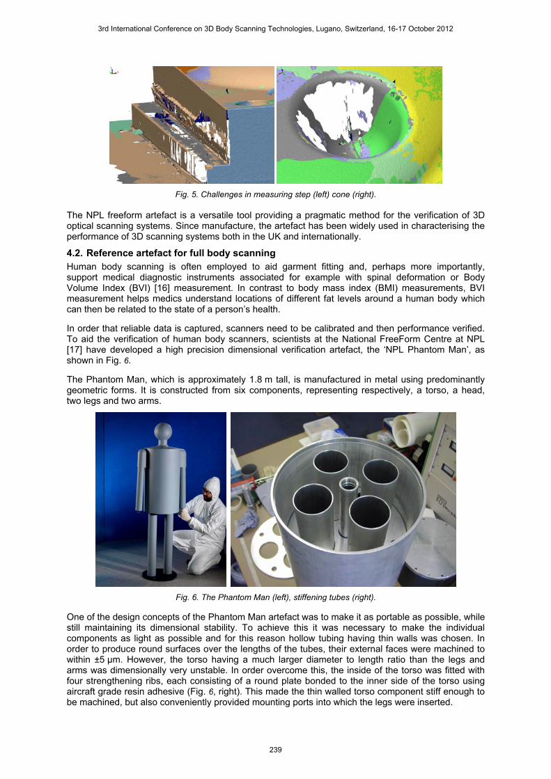
Fig. 5. Challenges in measuring step (left) cone (right). The NPL freeform artefact is a versatile tool providing a pragmatic method for the verification of 3D optical scanning systems. Since manufacture, the artefact has been widely used in characterising the performance of 3D scanning systems both in the UK and internationally.
4.2. Reference artefact for full body scanning Human body scanning is often employed to aid garment fitting and, perhaps more importantly, support medical diagnostic instruments associated for example with spinal deformation or Body Volume Index (BVI) [16] measurement. In contrast to body mass index (BMI) measurements, BVI measurement helps medics understand locations of different fat levels around a human body which can then be related to the state of a person’s health. In order that reliable data is captured, scanners need to be calibrated and then performance verified. To aid the verification of human body scanners, scientists at the National FreeForm Centre at NPL [17] have developed a high precision dimensional verification artefact, the ‘NPL Phantom Man’, as shown in Fig. 6. The Phantom Man, which is approximately 1.8 m tall, is manufactured in metal using predominantly geometric forms. It is constructed from six components, representing respectively, a torso, a head, two legs and two arms.
Fig. 6. The Phantom Man (left), stiffening tubes (right). One of the design concepts of the Phantom Man artefact was to make it as portable as possible, while still maintaining its dimensional stability. To achieve this it was necessary to make the individual components as light as possible and for this reason hollow tubing having thin walls was chosen. In order to produce round surfaces over the lengths of the tubes, their external faces were machined to within ±5 µm. However, the torso having a much larger diameter to length ratio than the legs and arms was dimensionally very unstable. In order overcome this, the inside of the torso was fitted with four strengthening ribs, each consisting of a round plate bonded to the inner side of the torso using aircraft grade resin adhesive (Fig. 6, right). This made the thin walled torso component stiff enough to be machined, but also conveniently provided mounting ports into which the legs were inserted.
3rd International Conference on 3D Body Scanning Technologies, Lugano, Switzerland, 16-17 October 2012
239

The final assembly of the Phantom Man was carried out on a cast iron optical bench. Its surface had been lapped and so acted as a reference plane, such that positions of the individual components could be adjusted during the assembly bonding process. Measurements during assembly were made using mechanical dial gauges and callipers. Once assembled, the shiny surface of the aluminium needed to be made more optical cooperative and this was uniformly coated with a tough acrylic grey paint which resulted in the production of a good Lambertian surface.
The Phantom Man was dimensioned using a high specification coordinate measuring machine employing a contacting probe (see Fig. 7, left). The NPL calibration data is not reported here, but Table 1 shows the nominal design dimensions of each component and the estimated measurement uncertainties.
Fig. 7. Calibration of the Phantom Man on a CMM (left), measurement of the phantom man
using a body scanner (right).
The Phantom man was then measured twice by a body scanner (see Fig. 7, right) and once by an industrial scanner. The results are shown in Table 2 and graphically represented in Fig. 8. The results from the body scanner suggest maximum deviations from the NPL data set in the order of 10 mm, while the high quality industrial scanner is better with all values being less than 1 mm from the reference values. It should be noted that the body scanner measured the Phantom Man repeatability to within nominally a few millimetres and therefore with a suitable calibration procedure the performance of the scanner examined may well be improved.
Table 1. Design and Estimated measurement uncertainty data for NPL Phantom Man.
Component Dimension Design measurement /mm Estimated uncertainty /mm
Head diameter 200 0.001 Neck diameter 99 0.001
Torso diameter 404 0.002
Arm diameter 75 0.001
length 480 0.002
Leg diameter 100 0.001
length 750 0.003
Upper torso height length 990 0.003
Total height length 1750 0.005
Table 2. Deviations from NPL reference data in mm.
Component Dimension Body Scanner Run 1 Body Scanner Run 2 Industrial Scanner Run 1
Head (1) diameter 1.046 1.146 -0.246 Neck (2) diameter 0.100 -1.510 0.110
Torso (3) diameter -9.341 -10.741 0.359
Arm (4) Left diameter -3.301 -5.701 -0.181
Arm (5) Left length 6.529 -0.071 -0.171
Leg (6) Left diameter -6.606 -7.706 -0.666
Leg (7) Left length 5.300 4.470 -0.029
Upper torso height (8)
length Not measured Not measured -0.199
Total height (9) length Not measured Not measured -0.966
3rd International Conference on 3D Body Scanning Technologies, Lugano, Switzerland, 16-17 October 2012
240
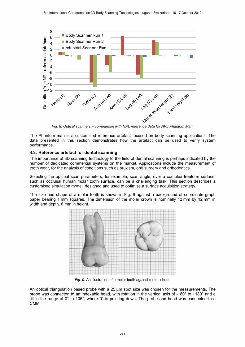
Fig. 8. Optical scanners – comparison with NPL reference data for NPL Phantom Man.
The Phantom man is a customised reference artefact focused on body scanning applications. The data presented in this section demonstrates how the artefact can be used to verify system performance.
4.3. Reference artefact for dental scanning The importance of 3D scanning technology to the field of dental scanning is perhaps indicated by the number of dedicated commercial systems on the market. Applications include the measurement of tooth wear, for the analysis of conditions such as bruxism, oral surgery and orthodontics. Selecting the optimal scan parameters, for example, scan angle, over a complex freeform surface, such as occlusal human molar tooth surface, can be a challenging task. This section describes a customised simulation model, designed and used to optimise a surface acquisition strategy. The size and shape of a molar tooth is shown in Fig. 9 against a background of coordinate graph paper bearing 1 mm squares. The dimension of the molar crown is nominally 12 mm by 12 mm in width and depth, 6 mm in height.
Fig. 9. An illustration of a molar tooth against metric sheet. An optical triangulation based probe with a 25 μm spot size was chosen for the measurements. The probe was connected to an indexable head, with rotation in the vertical axis of -180° to +180° and a tilt in the range of 0° to 105°, where 0° is pointing down. The probe and head was connected to a CMM.
3rd International Conference on 3D Body Scanning Technologies, Lugano, Switzerland, 16-17 October 2012
241

A laboratory based experiment, to scan a 25 mm sphere, was carried out using the probe in a combination of four different scan directions and orientations illustrated in Fig. 10. Firstly the direction of measurement was in the -X scanning direction and the diffused reflection was towards the probe sensor. The optical plane (defined by incident beam and reflection beam) was in line with the probe motion plane (This is recommended by the manufacturer). Secondly the direction of measurement was in the +X scanning direction, and the diffused reflection was backwards to the probe sensor. Thirdly the direction of measurement was in the +Y direction and fourthly in the –Y direction, the optical plane (XOZ) was perpendicular to the probe motion plane (YOZ), and diffused reflections were neither towards nor backwards to the probe sensor.
Fig. 10. An illustration of the investigation arrangement
along the X directions (left) and Y directions (middle and right). The data was analysed by assessing the error of the captured data for each of the four configurations, taking the reference surface data and subtracting the scan data in the X and Y directions. The difference of the subtraction was the error in each of the scans. The error in the X direction is shown in Fig. 11.
Fig. 11. The calculated error along the X direction.
This experiment demonstrates the importance of capturing data from a near-optimal scan angle. Selecting the right combination of scan angles during the data acquisition is essential in obtaining a good quality surface measurement.
3rd International Conference on 3D Body Scanning Technologies, Lugano, Switzerland, 16-17 October 2012
242

To address the problem of establishing the optimum scan parameters for molar tooth scanning a simulation artefact was made from four 6 mm diameter steel balls with good sphericity, rigidly assembled on a steel plate by NPL, as show in Fig. 12. The relative distance and height to each sphere was deliberately made unequal, to reflect the arbitrary relations of the cusps on occlusal molar tooth surfaces. Three balls at the corners of the plate act as datum features enabling comparative measurements to be made.
Fig. 12. The simulation model of the molar tooth surface, on the left (white) is a molar tooth surface, and on the right (blue) is an impression of the simulation model.
Initially based on the experience of the previous experiment, four probe orientations were selected to capture data from each of the four quadrants of the hemisphere, for each of the spheres. The four probe orientations were, (Tilt, vertical rotation); I: (45°, 45°), II: (45°, 135°), III: (-45°, 45°) and IV: (-45°, -135°). Fig. 13 shows a set of measured data captured using this measurement strategy. Two effects can be noticed from the plotted data points in Fig. 13. Firstly, the change in the spacing between measurement points, towards the edges of the image referred to as the spacing shift. Secondly the apparent bend in the lines of scan points, causing crossing where the quadrants meet.
Fig. 13. Data points measured using a four probe orientation measurement strategy. Units in millimetres.
Fig. 14 illustrates the configuration previously described. The sampling interval is defined by D. D is a constant value controlled by the CMM and the probe measurement system. The interaction between the probe orientation and surface curvature, therefore resulted in a variable spacing represented as the distance between a and b, with respect to the X and Y directions. These variations in the X and Y directions are due to the geometry of the sphere.
3rd International Conference on 3D Body Scanning Technologies, Lugano, Switzerland, 16-17 October 2012
243

X
Z
a
b
DD
a b
Z
Y
O
O
Ra Rb
A B
R
Z
Y
O
A - A B - B
Fig. 14. An illustration of the spacing shift, in the X (top) and Y (bottom) directions. To improve the problem of spacing shifts, a combination of six-probe orientations was chosen and implemented. The chosen six probe orientations were set to I: (0°, 180°), II: (30°,-45°), III: (30°,-135°), IV: (0°, 0°), V: (30°, 45°), and VI: (30°, 135°). Consequently, the tilt direction was reduced from 45° to 30°, the reduction of the shift was reduced by a factor of 1.7 in both directions of X and Y. This resulted in a more even distribution of data points as shown in Fig. 15 (compare with Fig. 13).
Fig. 15. Data points measured using a six probe orientation measurement strategy. Units in millimetres.
The measurement strategy was then applied to the simulation artefact including the molar tooth surface. The captured data is shown in Fig. 16.
3rd International Conference on 3D Body Scanning Technologies, Lugano, Switzerland, 16-17 October 2012
244

Fig. 16. A digitised image of the simulation model and occlusal tooth surface.
The simulation artefact enabled the theoretically developed measurement strategy to be tested ensuring that it resulted in a measured data set that adequately covered the features of interest.
5. Conclusions The adoption and implementation of 3D scanning systems is growing year on year as the technology continues to advance. This paper highlights some of the problems and challenges associated with using 3D scanning systems. For a given application it is often difficult to predict how a particular system will perform with regard to the quality of the scan data. This paper describes how these challenges can be addressed through the use of customised, application specific calibrated reference artefacts. Three examples are given together with their implementations, focussing on instrument evaluation, operator reproducibility and development of optimum measurement strategies. The approach is a general one that may be applied to many measurement challenges. Such artefacts could form the basis of (written and physical) standards in the future.
Acknowledgements The authors would like to thank David Putland for the assembly of the Phantom Man, Dr Alan Wilson for measurements made calibrating the Phantom Man, and to Nigel Cross for his involvement in the development of the dental simulation artefact. Finally the authors would like to acknowledge the financial support of the National Measurement Office, of the UK Department for Business, Innovation and Skills.
References 1. Vukašinović, N. Možina, J. Duhovnik, J., (2012): “Correlation between incident angle,
measurement distance, object, colour and number of acquired points at CNC laser scanning” Journal of Mechanical Engineering Vol 58, 1,23-28.
2. Boehler, W. Bordas Vicent, M. Marbs, A., (2003): “Investigating laser scanner accuracy” XIXth CIPA Symposium at Antalya, Turkey.
3. J. Clark, J. Robson S., (2004): “Accuracy of measurements made with a Cyrax 2500 laser scanner against surfaces of known colour”, Survey Review - Commonwealth Association of Surveying and Land Economy, 37 (294) pp. 626-638.
4. Lemeš, S. Zaimović-Uzunović, N., (2009) “Study of ambient light influence on laser 3D scanning”, 7th International conference on industrial tools and material processing technologies, Ljubljana, 327-330.
5. Luhmann, T, Wendt, K. (2000) “Recommendations for an acceptance and verification test for optical 3-d measurement systems”, International Archives of Photogrammetry and Remote Sensing. Vol. XXXIII, Part B5. Amsterdam.
6. VDI/VDE 2634 Part 1, “Optical 3D measuring systems: Imaging systems with point-by-point probing” The Association of German Engineers (VDI) Berlin, Germany, (2002).
7. VDI/VDE 2634 Part 2, “Optical 3D measuring systems: Optical systems based on area s canning” The Association of German Engineers (VDI) Berlin, Germany, (2002).
8. VDI/VDE 2634 Part 3, “Optical 3D measuring systems: Imaging systems based on area scanning in several singles images” The Association of German Engineers (VDI) Berlin, Germany, (2006).
3rd International Conference on 3D Body Scanning Technologies, Lugano, Switzerland, 16-17 October 2012
245

9. Robson, S. Beraldin, A. Brownhill, A. MacDonald,L.,( 2011): “Artefacts for optical surface measurement”, Conference on Videometrics, Range Imaging, and Applications XI. Spie-int soc optical engineering.
10. Savio, E. De Chiffre, L. Schmitt, R., (2007): “Metrology of freeform shaped parts” Annals of the CIRP Vol. 56/2/2007p810-836.
11. Carrier, B. MacKinnon, D. Cournoyer, L. Beraldin, A., (2011): “Proposed NRC portable target case for short range triangulation-based 3-D imaging systems characterisation”, Proceedings of the SPIE, Volume 7864, pp. 78640L-13.
12. Iuliano, L. Minetola, P. Salmi, A., (2010): “Proposal of an innovative benchmark for comparison of the performance of contactless digitizers”, Meas. Sci. Technol. 21 105102 (13pp).
13. Martínez, S. Cuesta, E. Barreiro, J. Álvarez, B., (2010): “Analysis of laser scanning and strategies for dimensional and geometrical control”, Int J Adv Manuf Technol 46:621–629.
14. Acko, B. McCarthy, M. Haertig, F. Buchmeister, B., (2011): “Standards for testing freeform measurement capability of optical and tactile coordinate measuring machines” Meas. Sci. Technol. 23 094013.
15. McCarthy, M. Brown, S. Evenden, A. Robinson A., (2011): “NPL Freeform artefact for the verification of non-contact, measuring systems.”, SPIE-IS&T Vol 7864 78640k1-3.
16. Barnes, R. Rahim, A., (2009) “The Body Volume Index: New Imaging Technology for Body measurement”, Hospital Imaging & Radiology Europe Autumn 2009 Vol 4.
17. The National Freeform Centre (accessed 2012): http://www.npl.co.uk/freeform
3rd International Conference on 3D Body Scanning Technologies, Lugano, Switzerland, 16-17 October 2012
246