improving the satellite power supply continuity using
TRANSCRIPT
euu:t:tthsk.mkevslantmhj.mhr ERJ
Engineering Research Journal
Faculty of Engineering
Menoufia University
ISSN: 1110-1180
DOI: ---------
ERJ, PART 1, ELE. Eng., Vol. 44 (4), October 2021, pp. 365 - 375
Improving the Satellite Power Supply Continuity Using
Flywheel Energy Storage System
Mohamed El Amir Attalla1, and Hassna M. El Arwash
2*
1Department of Electronics and Communications Eng., Alexandria higher Institute of
Engineering & Technology (AIET), Alexandria, Egypt. 2
Department of Mechatronics Eng., Alexandria higher Institute of Engineering & Technology
(AIET), Alexandria, Egypt.
(Corresponding author: [email protected])
ABSTRACT
Recently, Flywheel Energy Storage (FES) systems are gaining significant interest from National Aeronautics
and Space Administration Glenn Research Center (NASA's GRC) in satellite applications due to their
numerous advantages as an energy storage solution over the rest of the alternatives. Regarding FESS features
such as high cycle life, long service life, high efficiency, high energy density and low environmental impact,
this paper introduces a FESS management controller for use with the solar PV system in an integrated
manner that ensures the continuity of the satellite power system and, thus, increases its efficiency. In
addition, a prototype of the management control under various operating modes of the proposed unit is
established. The satellite power supply management controller was implemented practically as a model using
the Arduino controller. The practical results proved the continuity of the satellite operation in different
operating modes using the FES system, which in turn would lead to improving the efficiency of the satellite
feeding source compared to its performance using solar PV system only.
Keywords: Flywheel; satellite power supply; solar PV system.
1. Introduction
Currently, the operation of the International Space
Station (ISS) is accomplished using several solar
arrays, which are made up of several solar cells, or
photovoltaic. It is expected in the coming years that
more arrays will be added as space stations continue
to be built. The idea of photovoltaic is based on the
production of an electric current from sunlight after
directing the cells towards the sun to capture as much
light as possible. During daylight, the solar cells
operate the vehicle directly and, at the same time, the
energy storage unit, represented by nickel and
hydrogen, is charged. The batteries are characterized
by their ability to be recharged in order to provide the
necessary energy for the station when the station is in
the shade. The station is located in low Earth orbit,
which leads to an increase in the duration of the
station in the shade for up to 36 minutes from its 92-
minute orbit. Therefore, these batteries are
continuously discharged and recharged [1m]
Although electrochemical batteries are a source of
energy storage for the station when it enters Earth's
shadow in every orbit, NASA is focusing its research
on an improved way to store electricity on spacecraft.
Due to many important disadvantages of
electrochemical batteries, such as rechargeable nickel
and hydrogen batteries, they have a limited number
of discharging and recharging cycles, which forces
the worn out batteries to be replaced in the space
shuttle. This represents an expensive process in terms
of the actual cost of the batteries, the lost charge
space and at the time of installation [2] .
Recently, flywheels have been on the list of storage
technologies in electrical energy storage applications
due to their advantages such as high energy
efficiency, high energy and high energy density.
Moreover, the most important parameters of FESS
for satellite applications are efficiency, lifetime,
reliability, operating temperature, weight, volume,
and system cost. Additionally, flywheel systems
perform the same function as rechargeable
electrochemical batteries, in addition to their recent
better performance in many ways m [3 ]
Over the past ten years, numerous developments have
taken place in the flywheels in terms of materials
with which they can be built [3, 4] and the method
for controlling their performance, which has
increased their capabilities [5- 8], while others
365

Mohamed El Amir Attalla, and Hassna M. El Arwas "Improving the Satellite Power Supply Continuity
using Flywheel Energy Storage System"
366 ERJ, Menoufia University, Vol. 44 , No. 4 , October 2021
concentrated on the flywheel sizing and its different
applications [9, 10]. Therefore, the flywheel storage
capacity is higher than the past. This means that the
energy that can be stored in the flywheel, i.e., its
kinetic energy, is much greater than the energy stored
in an electrochemical battery on a mass basism
A lot of studies and researches have been done and
prepared to develop the FESS so that it can be used in
many applications, and this was studied through three
directions. The first one is through the internal
development of the flywheel system in order to
improve performance and reduce size for ease of use,
but this direction experienced many difficulties. The
second direction dealt with the development through
the control system in the flywheel, but the limitations
of this direction appeared in many applications. The
third direction was focused on the adaptation of the
application depending on the type of the applicationm
Regarding flywheel interior design development, a
comparison of energy storage technologies have been
performed in 2011 [3] by R. Peña-Alzola et al. The
numerical and graphical review illustrated the
different improvements and issues associated with
FESS interior design. In 2011, a design was
presented to build a long-lifetime flywheel with
minor maintenance need for high energy density,
supported by radial and axial magnetic bearings of
low energy consumption. Thus, the energy-saving
magnetic bearings flywheel is developed and verified
via simulation and experimental investigations [4].
Also, in 2013, a flywheel associated with a grid-
connected variable-speed wind generation scheme,
using a Doubly-Fed Induction Generator (DFIG), has
been investigated [5]. Consequently, the dynamic
behavior of a wind generator, including models of the
wind turbine, DFIG, matrix converter, converter
control and power control, has been studied.
Moreover, the control method of the flywheel energy
storage system has been investigated with a classical
squirrel-cage Induction Machine (IM) associated with
a variable speed wind generation using cascade
rectifier filter. Jiqiang Tang et al., introduced in 2018
a rotor’s suspension stability control system [6m]
Other researchers focused on the Flywheel interior
control system to sustain its effectiveness during
operation. In 2013, Chi Zhang et al. have developed a
mathematical model of flywheel’s force and torque
[7, 8]. Based on PID controller, the control systems
of the flywheel position and velocity have been
designed. The proposed flywheel speed control
systems were experimentally carried out and tested to
prove the feasibility and correctness of the
mathematical analysis of the proposed model. The
proposed method, entitled “Cross Feedback Control
(CFC)”, was studied to ensure that the rotor’s
suspension is stable due to the whirling. A CFC
method, with pre-modulated gains, proved its
effectiveness and sustained the suspension stability
under a wider range of speeds. Also, an optimal
nonlinear controller was proposed in 2019 [9] based
on Model Predictive Control (MPC) for a flywheel
energy storage system in which the constraints on the
system states and actuators were taken into account.
Tube-based MPC was utilized as a robust controller
to control the system modeling uncertainties and the
external disturbances effect. The proposed method
merits in controlling the dc link voltage and the
flywheel speed response were demonstrated via
simulation results. Up till now, the improvement of
the internal flywheel design is still under studym
On the other hand, the application of flywheel in an
integrated manner with other energy storage systems
has been discussed in several researches. In 2013, the
authors designed two energy storage systems based
on chemical batteries and flywheel to optimize the
energy requirement of typical Low Earth Orbit (LEO)
satellites [10]. In addition, a comparison between the
two systems was investigated considering their
efficiency, reliability, weight, operational
temperature and self-discharge dissipation to
conclude the recommendations about their use in
terms of their capability. Moreover, T. Elsayed et al.,
2016, designed a controller to regulate the charging
rate through controlling the flywheel terminal voltage
[11]. Two modes of operations have been studied in
this research, i.e., charging and discharging modes. In
the charging mode, the converter operates in the buck
mode, while it operates in the boost mode in the
discharging mode. A current controller takes over the
control of the injected current from the machine to
the DC bus m
The researchers assert that the energy capacity stored
per unit mass in a flywheel system is much greater
than that in electrochemical batteries, and flywheels
can be discharged at a higher rate as well, which
means more available stored energy. It is also found
that up to 80% more energy could be recovered from
flywheels compared to electrochemical batteries
under the same conditions. The depth of discharge
adds several advantages to the flywheel. In terms of
weight, flywheel systems are lighter than
electrochemical batteries for the same storage
capacity, which is one of the most important
advantages, especially in applications where weight
is a limiting factor such as spacecraft. In terms of
increasing the charging and discharging cycles, the
flywheel can also withstand more cycles, while
reducing wear and tear on the system results in
extended life. While the life of the electrochemical
battery is between four and five years in the
Mohamed El Amir Attalla, and Hassna M. El Arwash "Improving the Satellite Power Supply Continuity
using Flywheel Energy Storage System"
ERJ, Menoufia University, Vol. 44 , No. 4 , October 2021 367
international space station (ISS), the flywheel lasts
between 15 and 20 years. Each ISS module has a
planned lifetime of 10 years [12].
This article proposes a management unit for
controlling the power supply feeding the satellite sub-
systems in the presence of a flywheel, batteries, and
solar cells to ensure the continuity feeding for the
subsystems that operate incessantly and reliably
leading to higher efficiency of the satellites.
Therefore, the use of the flywheel as a source of
energy storage for satellites enables them to fly in
LEO and Geosynchronous Equatorial Orbit (GEO)
orbits. Moreover, it presents the continuity and
reliability and how the proposed management control
unit increases the satellite's efficiency under different
modes of operations. A prototype system is
implemented for realistic results and conclusions.
Extensive simulation results are introduced to
compare the behavior of satellite power supply with
and without Flywheel to investigate the high
accuracy of the introduced approach.
2. Aim and Research Significance
Flywheel Energy Storage System (FESS)
Flywheel energy storage (FES) systems are featured
by their long lifetimes with maintenance free
compared to other storage methods, environmentally
friendly electricity storage technology that can
replace lead-acid batteries. When the stored energy
had recovered from the system, the flywheel rotation
speed decreased due to the principle of energy
conservation. Adding energy to the system, in turn,
increases the flywheel speed.
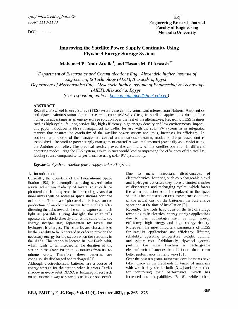
Flywheel Description
A flywheel is a rapidly rotating cylinder or disc
suspended in an airtight container that stores
electrical energy. The new generation of FES satellite
systems consists of a flywheel supported by rolling-
element magnetic bearing connected to a motor–
generator enclosed in a vacuum chamber. The
importance of the magnetic bearing is to reduce
friction and energy loss. However, the rotor is made
of high-strength carbon fiber composites that have a
higher tensile strength and can store much more
energy for the same mass, while spinning at speeds of
up to 50,000 rpm in a vacuum container. Moreover,
the flywheel can reach its capacity in a matter of
minutes [11, 13]. Due to their low weight, high
energy density, high efficiency, high reliability and
high speed, Brushless DC (BLDC) motors are the
most common type used in FESS. Figure 1 shows the
main components of the FES satellite as approved by
NASA.
Fig. 1: The main components of the satellite FESS
as approved by NASA
Form of energy storage
Flywheel is considered one of the most commonly-
used energy storage systems all over the world. In
this section the form of energy storage inside the
flywheel will be explained briefly. As mentioned in
[14], the flywheel moment of inertia is calculated
using Eq. (1) depending on different cylinder
shapes. The angular velocity and stored rotational
energy are calculated using Equations (2) and (3),
respectively.
where:
m : is the integral of the flywheel's mass, and
: is the rotational speed (number of revolutions
per second).
Specific energy
The maximal specific energy of a flywheel rotor is
mainly dependent on two factors: the first is the
rotor's geometry and the second is the properties 𝜎
and 𝜌 of the material being used. For a single-
material, isotropic rotors, this relationship can be
expressed by Eq. (4) as mentioned in [11].
(
) (4)
where:
E: is kinetic energy of the rotor [J],
m: is the rotor's mass [kg],
K: is the rotor's geometric shape factor
[dimensionless],
𝜎: is the tensile strength of the material [Pa], and
𝜌: is the material's density [kg/m3].
In the following, the two main factors affecting the
maximum specific power of the flywheel rotor will
Moment of inertia: ∫
(1)
Angular velocity: (2)
Stored rotational energy:
(3)
Mohamed El Amir Attalla, and Hassna M. El Arwas "Improving the Satellite Power Supply Continuity
using Flywheel Energy Storage System"
368 ERJ, Menoufia University, Vol. 44 , No. 4 , October 2021
be discussed briefly.
1. The geometry of the rotor (shape factor)
The highest possible value for the shape factor of a
flywheel rotor, is K=1, which can be achieved only
by the theoretical constant-stress disc geometry
[14]. A constant-thickness disc geometry has a
shape factor of K= 0.606, while the value is
K=0.333 for a rod of constant thickness. A thin
cylinder has a shape factor of K=0.5. For most
flywheels with a shaft, the shape factor is below or
about K=0.333. A shaft-less design [14] has a shape
factor similar to a constant-thickness disc (K=0.6),
which enables a doubled energy density.
2. deasatuhsutuutt et ueh tv.tualth vthC
For energy storage, materials with high strength and
low density are desirable. For this reason, composite
materials are frequently used in advanced flywheels.
The strength-to-density ratio of a material can be
expressed in Wh/kg (or Nm/kg), where values
greater than 400 Wh/kg can be achieved by certain
composite materials [14].
ewiSeetiSletaSelet iScleS metsittrl
Solar photovoltaic installation usually requires a solar
cell array, energy storage device, maximum power
tracker (MPPT), and DC-to-DC converter. The
MPPT is very important to extracts the maximum
available power under various conditions of solar
array. In the following subsections, a highlight will
be spotted about the main satellite power system
components.
Solar arrays
In satellite application, to have a peak generated
power during daylight, it is obligatory to design the
solar array using the following steps [15]:
1. Selection of the solar cells type;
2. Determining the solar array power capability;
3. Estimating the output power per unit area of the
solar array;
4. Estimating the required output power at the
Beginning Of Life (BOL) of the satellite;
5. Estimating the output power at the satellite End
Of Life (EOL).
In the following, a brief discussion about each step
will be demonstrated:
1. Selection of the solar cells type:
The most important parameters in solar cells for
satellites applications are efficiency and lifetime.
Triple junction 3J (GaInP/GaInAs/Ge) cells are
recommended for both small and LEO satellites since
they have higher efficiency than GaAs cells [16].
Although the cost of the 3J cells is higher than GaAs,
they are smaller and lighter compared to GaAs cells.
This presents big funds for the launching costs, while
satisfying the same power capability of the larger and
heavier GaAs arrays.
Determining the solar array power capability:
The total extent of the generated power, which can be
achieved by the solar array during the non-shadowing
periods, is determined by summing the power
requirements of the spacecraft subsystems during
daylight and the needed power to charge the
secondary batteries to fulfill the eclipse power
demands. The solar array generated power can be
expressed as, [17]m
= 9.34 kW (5)
where:
, : are the spacecraft power requirements
during eclipse and daylight, respectively,
, : are the eclipse and the daylight durations for
the satellite in its orbit, respectively,
,
: are the efficiency of the spacecraft power
subsystem to supply the power from the array
to the loads in daylight and to the batteries for
charging during daylight, respectively.
Estimating the output power per unit area of the
solar array:
The output power per unit area ( ) can be
calculated by multiplying the efficiency of the PV
material (ƞ) by the solar irradiance intensity ( )
[17]. Since the 3J cells power efficiency is 30.7%
and using solar irradiance intensity =1321w/m
2
And Po can be calculated using equations (6), (7),
respectively.
(6)
= solar irradiance intensity × ƞ = 405.547 W/m2
(7)
Estimating the required output power at the
beginning of life (BOL) of the satellite
The required power at the beginning of life is given
by:
= = 312.27 Watt (8)
where is the incidence angle between the vector
Mohamed El Amir Attalla, and Hassna M. El Arwash "Improving the Satellite Power Supply Continuity
using Flywheel Energy Storage System"
ERJ, Menoufia University, Vol. 44 , No. 4 , October 2021 369
normal to the solar arrays and the direction of the
sun line ( = in worst case) [17]. In the
presented design, 0 since the satellite uses
a power tracking mechanism.
Estimating the output power at the satellite end
of life (EOL):
The power degradation factor (Ld) through the
satellite lifetime is calculated as:
(9)
As mention before, the degradation per year for 3J
solar cell is 0.5%. Therefore, the output power at
the satellite EOL can be estimated as:
(10)
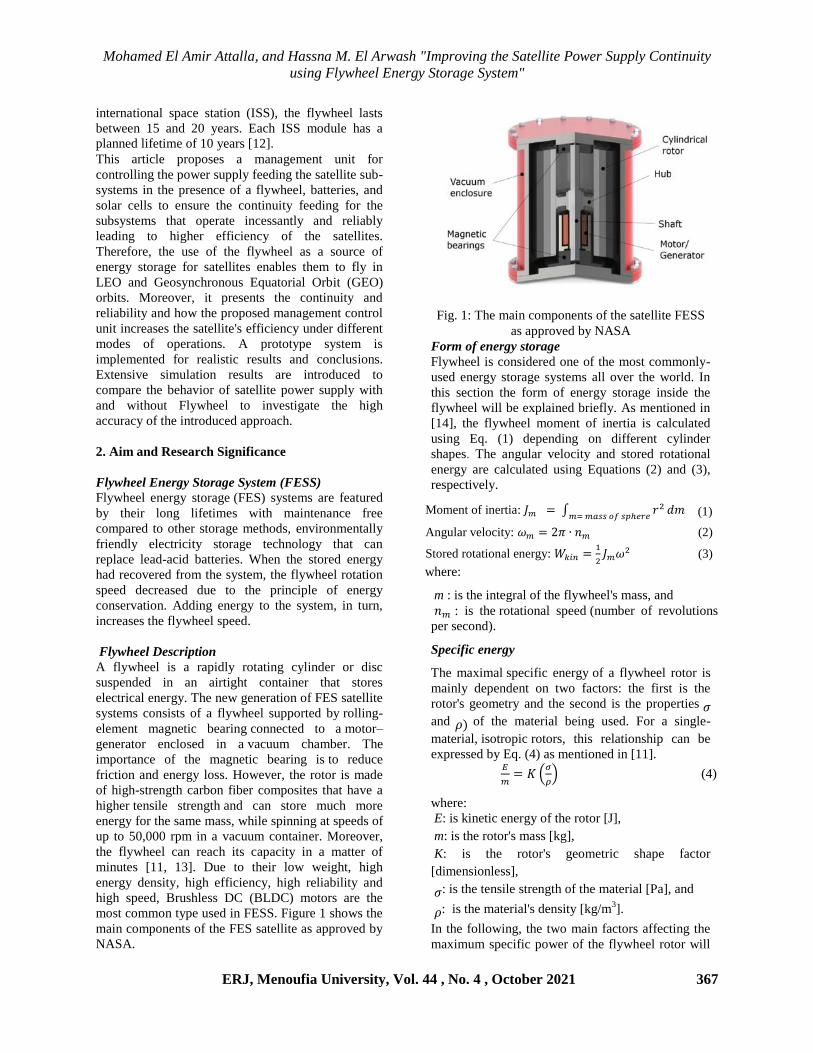
By comparing the performance of solar panels that
use 3J solar cells with panels that use GaAs solar
cells, it is found that the performance of the
manufactured cells of the first type is much better
than the second type, due to the 3J cells higher
efficiency. Figure 3 illustrates the degradation in the
output power delivered to the power subsystem over
the life of the satellite using the cell types 3J and
GaAs. It can be noticed that, the degradation rate of
3J cells is much lower than that of GaAs.
Fig. 3: Output power degradation over the satellite
lifetime
Battery Base Energy Storage System
Two common types of batteries, which are used in
space programs, are Ni-Cd and Ni-H2.
In the following, Table (1) depicts the properties of
these batteries [18].
Table 1: Properties of Ni-Cd and Ni-H2 batteries [18]
sauuhsz rse:hsuuht iu-dC iu-22
y:htutut hlhsrz(getjr) 33 63
flhsrz httutuhltz )%( 72 73
yhnt-Cutteasrh t%Caz)) 3m5 5
eh.:hsauvsh salrh (d˚) -15 ue 43 -23 ue 53
dhnn wenuarh (V) 1m2 1m2
th.esz htthtu sht sht
From Table (1), it can be demonstrated that Ni-Cd
has a lower stored energy for the same weight.
Although the self-discharge rate of Ni-H2 is more
than Ni-Cd, but in LEO satellites, charge and
discharge duration is very short and, so, the effect of
this parameter is negligible. Also, operational
temperature range of Ni-H2 (from -20 to 50 °C) is
more than Ni-Cd (from -15 to 40 °C) [18]. Therefore,
Ni-H2 is more suitable for Chemical Battery Energy
Storage System (CBESS) in this application.
The satellite sample power consumption is 40 watts
for 30 minutes (20 watt hours) in the duration of the
eclipse, and the maximum permissible depth of
discharge for chemical batteries in LEO is 15% [19].
Therefore, the power capacity for batteries should be
as follows:
Batteries Capacity =
5
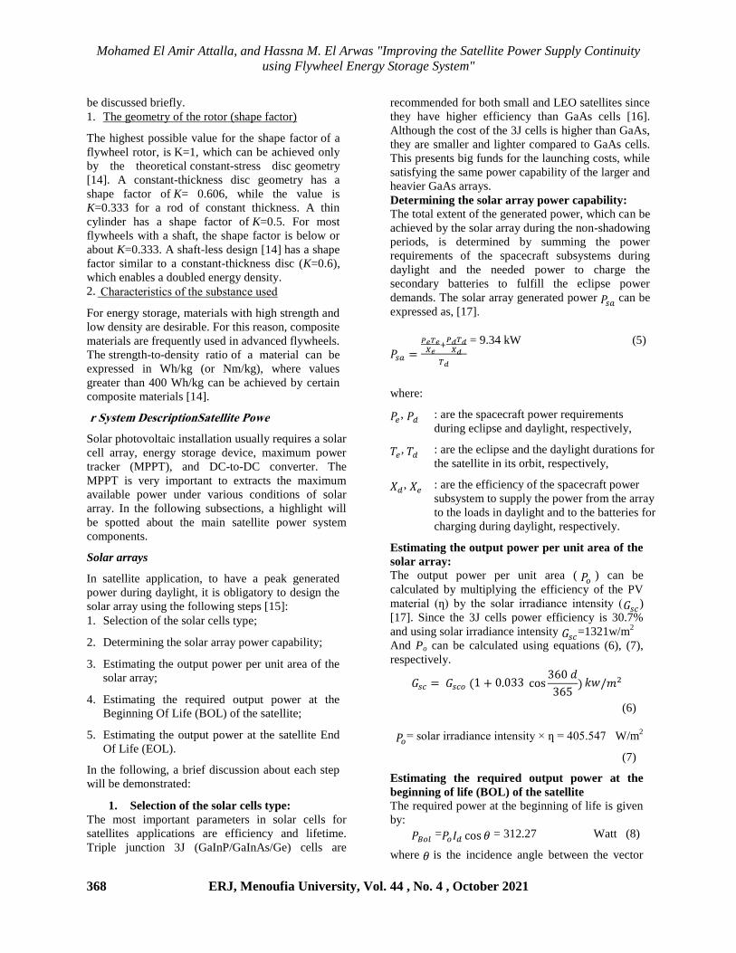
3. Model Approach of Satellite Power System
3.1 Satellite Power System without FESS
Generally, load energy storage systems are
connected through series and parallel structures.
Parallel structure has greater overall efficiency [20].
Moreover, different topologies are used as DC-DC
converter in satellite power transmission system.
Each topology has its own advantages and
disadvantages [21]. Bidirectional push-buck
topology is the topology most suggested in previous
studies. The efficiency of the CBESS power
electronics based on this chassis is about 95%.
Fig. 4: Bidirectional boost-buck converter with
parallel connection for a CBESS for satellite
applications without FESS
Figure 4 shows the parallel structure of a DC-DC
bi-directional converter for CBESS and the batteries
are connected to the DC bus through a two-way
DC-DC converter in a parallel mannerm
For satellite, there are three modes of operation
related to sunlight as shown in Fig. (5). In the
following, a brief discussion about the three modes
according to sunlight will be demonstrated m
0
500
1 5 10 15 20Number of years through satellite lifetime
3J GaAS
Gen
erat
ed
po
wer
(W
/m2
)
Solar panels
Batteries
DC-DC Converter
Control unit
Load
Mohamed El Amir Attalla, and Hassna M. El Arwas "Improving the Satellite Power Supply Continuity
using Flywheel Energy Storage System"
370 ERJ, Menoufia University, Vol. 44 , No. 4 , October 2021
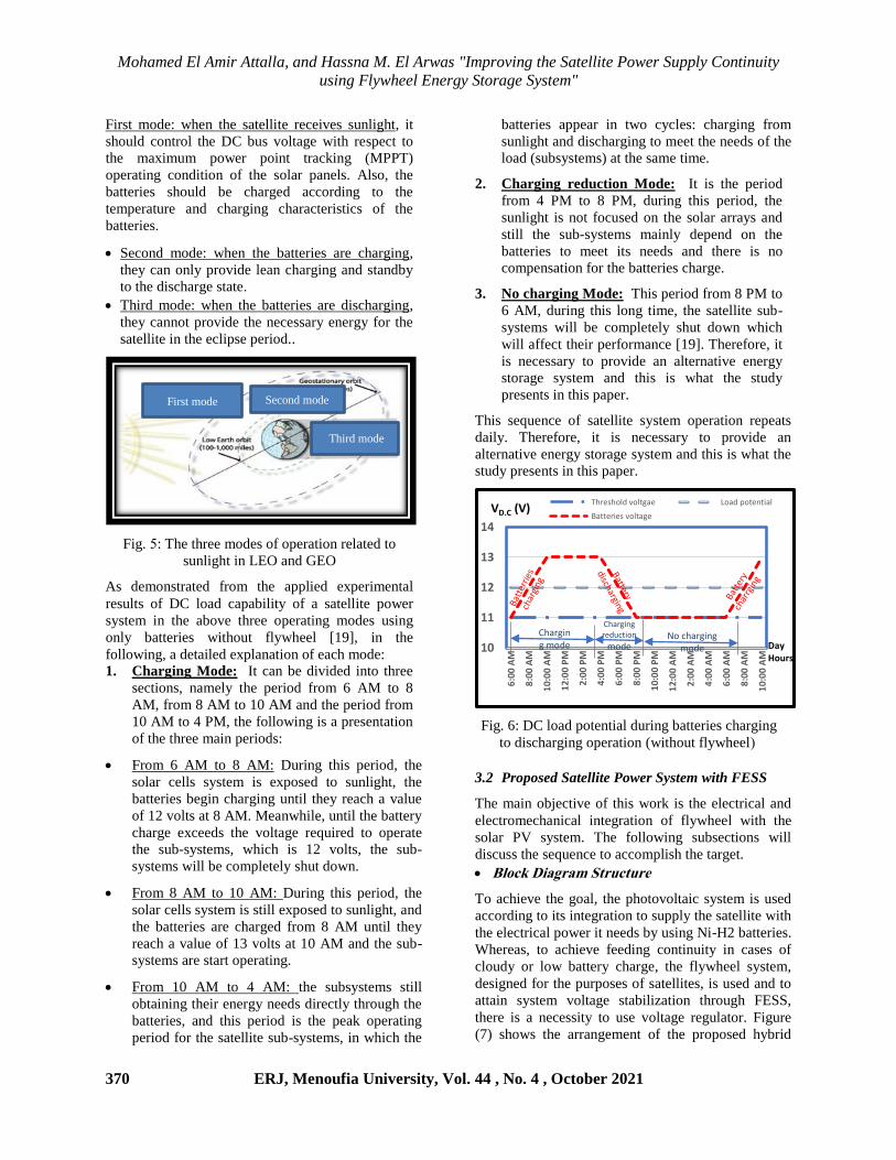
First mode: when the satellite receives sunlight, it
should control the DC bus voltage with respect to
the maximum power point tracking (MPPT)
operating condition of the solar panels. Also, the
batteries should be charged according to the
temperature and charging characteristics of the
batteriesm
Second mode: when the batteries are charging,
they can only provide lean charging and standby
to the discharge statem
Third mode: when the batteries are discharging,
they cannot provide the necessary energy for the
satellite in the eclipse period..
Fig. 5: The three modes of operation related to
sunlight in LEO and GEO
As demonstrated from the applied experimental
results of DC load capability of a satellite power
system in the above three operating modes using
only batteries without flywheel [19], in the
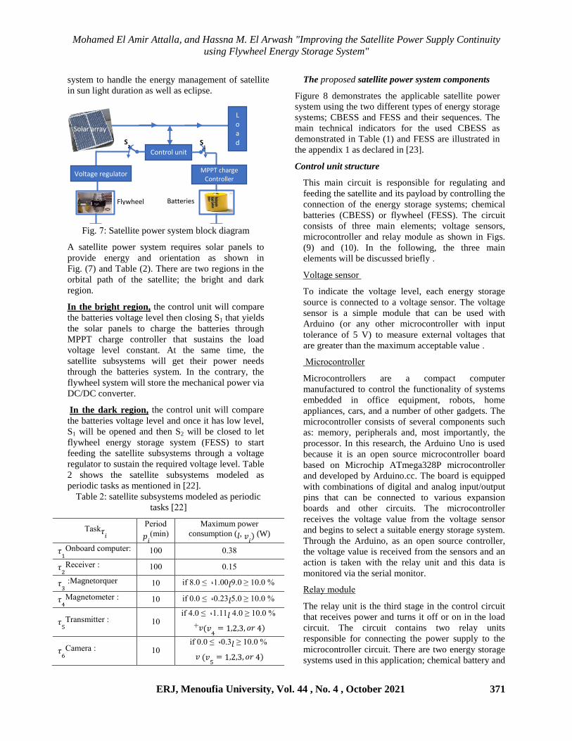
following, a detailed explanation of each mode: 1. Charging Mode: It can be divided into three
sections, namely the period from 6 AM to 8
AM, from 8 AM to 10 AM and the period from
10 AM to 4 PM, the following is a presentation
of the three main periods:
From 6 AM to 8 AM: During this period, the
solar cells system is exposed to sunlight, the
batteries begin charging until they reach a value
of 12 volts at 8 AM. Meanwhile, until the battery
charge exceeds the voltage required to operate
the sub-systems, which is 12 volts, the sub-
systems will be completely shut down.
From 8 AM to 10 AM: During this period, the
solar cells system is still exposed to sunlight, and
the batteries are charged from 8 AM until they
reach a value of 13 volts at 10 AM and the sub-
systems are start operating.
From 10 AM to 4 AM: the subsystems still
obtaining their energy needs directly through the
batteries, and this period is the peak operating
period for the satellite sub-systems, in which the
batteries appear in two cycles: charging from
sunlight and discharging to meet the needs of the
load (subsystems) at the same time.
2. Charging reduction Mode: It is the period
from 4 PM to 8 PM, during this period, the
sunlight is not focused on the solar arrays and
still the sub-systems mainly depend on the
batteries to meet its needs and there is no
compensation for the batteries charge.
3. No charging Mode: This period from 8 PM to
6 AM, during this long time, the satellite sub-
systems will be completely shut down which
will affect their performance [19]. Therefore, it
is necessary to provide an alternative energy
storage system and this is what the study
presents in this paper.
This sequence of satellite system operation repeats
daily. Therefore, it is necessary to provide an
alternative energy storage system and this is what the
study presents in this paper.
Fig. 6: DC load potential during batteries charging
to discharging operation (without flywheel (
3.2 Proposed Satellite Power System with FESS
The main objective of this work is the electrical and
electromechanical integration of flywheel with the
solar PV system. The following subsections will
discuss the sequence to accomplish the target.
eetmcletw ewcleieomioeSl
To achieve the goal, the photovoltaic system is used
according to its integration to supply the satellite with
the electrical power it needs by using Ni-H2 batteries.
Whereas, to achieve feeding continuity in cases of
cloudy or low battery charge, the flywheel system,
designed for the purposes of satellites, is used and to
attain system voltage stabilization through FESS,
there is a necessity to use voltage regulator. Figure
(7) shows the arrangement of the proposed hybrid
10
11
12
13
14
6:0
0 A
M
8:0
0 A
M
10:
00
AM
12:
00
PM
2:0
0 P
M
4:0
0 P
M
6:0
0 P
M
8:0
0 P
M
10:
00
PM
12:
00
AM
2:0
0 A
M
4:0
0 A
M
6:0
0 A
M
8:0
0 A
M
10:
00
AM
Threshold voltgae Load potential
Batteries voltageVD.C (V)
Day Hours
First mode Second mode
Third mode
Charging mode
No charging mode
Charging reduction
mode
Mohamed El Amir Attalla, and Hassna M. El Arwash "Improving the Satellite Power Supply Continuity
using Flywheel Energy Storage System"
ERJ, Menoufia University, Vol. 44 , No. 4 , October 2021 371
system to handle the energy management of satellite
in sun light duration as well as eclipse.
Fig. 7: Satellite power system block diagram
A satellite power system requires solar panels to
provide energy and orientation as shown in
Fig. (7) and Table (2). There are two regions in the
orbital path of the satellite; the bright and dark
region.
In the bright region, the control unit will compare
the batteries voltage level then closing S1 that yields
the solar panels to charge the batteries through
MPPT charge controller that sustains the load
voltage level constant. At the same time, the
satellite subsystems will get their power needs
through the batteries system. In the contrary, the
flywheel system will store the mechanical power via
DC/DC converter.
In the dark region, the control unit will compare
the batteries voltage level and once it has low level,
S1 will be opened and then S2 will be closed to let
flywheel energy storage system (FESS) to start
feeding the satellite subsystems through a voltage
regulator to sustain the required voltage level. Table
2 shows the satellite subsystems modeled as
periodic tasks as mentioned in [22].
Table 2: satellite subsystems modeled as periodic
tasks [22]
The proposed satellite power system componentsl
Figure 8 demonstrates the applicable satellite power
system using the two different types of energy storage
systems; CBESS and FESS and their sequences. The
main technical indicators for the used CBESS as
demonstrated in Table (1) and FESS are illustrated in
the appendix 1 as declared in [23].
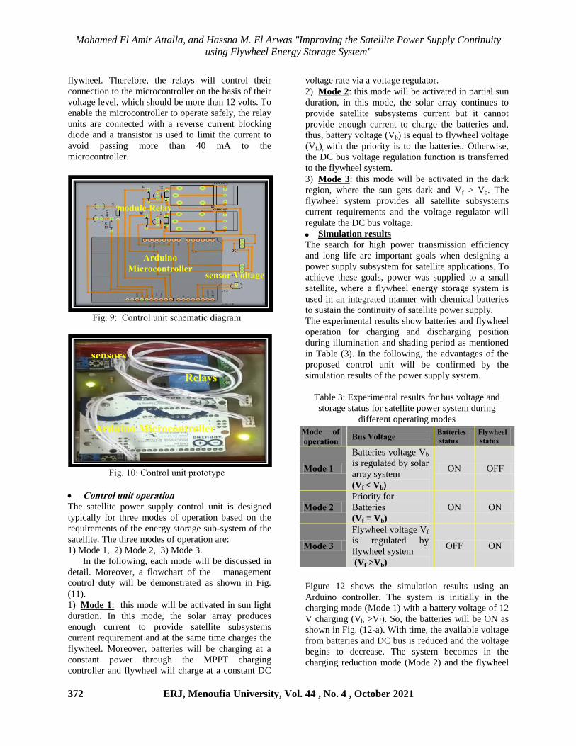
Control unit structure
This main circuit is responsible for regulating and
feeding the satellite and its payload by controlling the
connection of the energy storage systems; chemical
batteries (CBESS) or flywheel (FESS). The circuit
consists of three main elements; voltage sensors,
microcontroller and relay module as shown in Figs.
(9) and (10). In the following, the three main
elements will be discussed briefly m
Voltage sensor
To indicate the voltage level, each energy storage
source is connected to a voltage sensor. The voltage
sensor is a simple module that can be used with
Arduino (or any other microcontroller with input
tolerance of 5 V) to measure external voltages that
are greater than the maximum acceptable value m
tutsetelusennhs
Microcontrollers are a compact computer
manufactured to control the functionality of systems
embedded in office equipment, robots, home
appliances, cars, and a number of other gadgets. The
microcontroller consists of several components such
as: memory, peripherals and, most importantly, the
processor. In this research, the Arduino Uno is used
because it is an open source microcontroller board
based on Microchip ATmega328P microcontroller
and developed by Arduino.cc. The board is equipped
with combinations of digital and analog input/output
pins that can be connected to various expansion
boards and other circuits. The microcontroller
receives the voltage value from the voltage sensor
and begins to select a suitable energy storage system.
Through the Arduino, as an open source controller,
the voltage value is received from the sensors and an
action is taken with the relay unit and this data is
monitored via the serial monitor.
ehnaz .eCvnh
The relay unit is the third stage in the control circuit
that receives power and turns it off or on in the load
circuit. The circuit contains two relay units
responsible for connecting the power supply to the
microcontroller circuit. There are two energy storage
systems used in this application; chemical battery and
eatj 𝜏
rhsueC
(.ul)
Maximum power
consumption (𝑙, 𝑣 (W)
𝜏
:rl.easC te.:vuhs 133 3m38
𝜏
:ehthuwhs 133 3m15
𝜏3 :Magnetorquer 13 1m33 ,ut 8m3 f 𝑙 %13m3 ≤9m3
𝜏4
:tarlhue.huhs 13 3m23 ,ut 3m3 f 𝑙 %13m3 ≤5m3
𝜏5
: esalt.uuuhs 13 1m11 ,ut 4m3 f 𝑙 %13m3 ≤4m3
+𝑣 𝑣4
𝜏6
:da.hsa 13 3m3 ,ut 3m3 f 𝑙 %13m3 ≤
𝑣 𝑣5
Load
Control unit
Voltage regulator MPPT charge
Controller
S1 S
2
Flywheel Batteries
Solar array
Mohamed El Amir Attalla, and Hassna M. El Arwas "Improving the Satellite Power Supply Continuity
using Flywheel Energy Storage System"
372 ERJ, Menoufia University, Vol. 44 , No. 4 , October 2021
flywheel. Therefore, the relays will control their
connection to the microcontroller on the basis of their
voltage level, which should be more than 12 volts. To
enable the microcontroller to operate safely, the relay
units are connected with a reverse current blocking
diode and a transistor is used to limit the current to
avoid passing more than 40 mA to the
microcontroller.
gurm 9: delusen vluu tteh.auut Cuarsa.
gurm 13: delusen vluu :seueuz:h
ntrietelortiltsSewittrl The satellite power supply control unit is designed
typically for three modes of operation based on the
requirements of the energy storage sub-system of the
satellite. The three modes of operation are:
1) Mode 1, 2) Mode 2, 3) Mode 3.
In the following, each mode will be discussed in
detail. Moreover, a flowchart of the management
control duty will be demonstrated as shown in Fig.
(11).
1) Mode 1: this mode will be activated in sun light
duration. In this mode, the solar array produces
enough current to provide satellite subsystems
current requirement and at the same time charges the
flywheel. Moreover, batteries will be charging at a
constant power through the MPPT charging
controller and flywheel will charge at a constant DC
voltage rate via a voltage regulator.
2) Mode 2: this mode will be activated in partial sun
duration, in this mode, the solar array continues to
provide satellite subsystems current but it cannot
provide enough current to charge the batteries and,
thus, battery voltage (Vb) is equal to flywheel voltage
(Vf.), with the priority is to the batteries. Otherwise,
the DC bus voltage regulation function is transferred
to the flywheel system.
3) Mode 3: this mode will be activated in the dark
region, where the sun gets dark and Vf > Vb. The
flywheel system provides all satellite subsystems
current requirements and the voltage regulator will
regulate the DC bus voltage.
Simulation results
The search for high power transmission efficiency
and long life are important goals when designing a
power supply subsystem for satellite applications. To
achieve these goals, power was supplied to a small
satellite, where a flywheel energy storage system is
used in an integrated manner with chemical batteries
to sustain the continuity of satellite power supply.
The experimental results show batteries and flywheel
operation for charging and discharging position
during illumination and shading period as mentioned
in Table (3). In the following, the advantages of the
proposed control unit will be confirmed by the
simulation results of the power supply system.
Table 3: Experimental results for bus voltage and
storage status for satellite power system during
different operating modes
toSl tol
tsSewittr eo llteiw S
ewiiSetS l
iwio
etahSSel
iwio
toSlM
Batteries voltage Vb
is regulated by solar
array system
(Vf < Vb)
ri rgg
toSlM
Priority for
Batteries
(Vf = Vb)
ri ri
toSlM
Flywheel voltage Vf
is regulated by
flywheel system
(Vf >Vb)
rgg ri
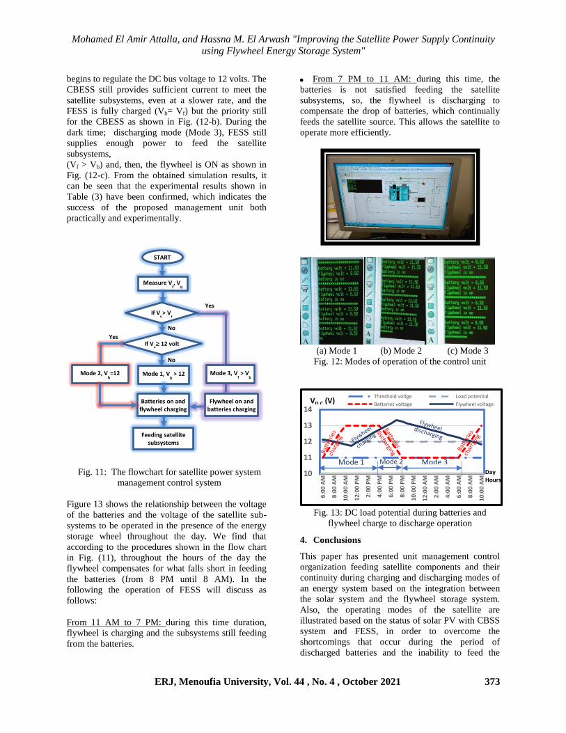
Figure 12 shows the simulation results using an
Arduino controller. The system is initially in the
charging mode (Mode 1) with a battery voltage of 12
V charging (Vb >Vf). So, the batteries will be ON as
shown in Fig. (12-a). With time, the available voltage
from batteries and DC bus is reduced and the voltage
begins to decrease. The system becomes in the
charging reduction mode (Mode 2) and the flywheel
Aeootrtl tmetmtrieteeSe
Sr te
RSewt
Aeootrtl
tmetmtrieteeSe
RSewtlctooeS
lteiw Sl Sr tel
Mohamed El Amir Attalla, and Hassna M. El Arwash "Improving the Satellite Power Supply Continuity
using Flywheel Energy Storage System"
ERJ, Menoufia University, Vol. 44 , No. 4 , October 2021 373
begins to regulate the DC bus voltage to 12 volts. The
CBESS still provides sufficient current to meet the
satellite subsystems, even at a slower rate, and the
FESS is fully charged (Vb= Vf) but the priority still
for the CBESS as shown in Fig. (12-b). During the
dark time; discharging mode (Mode 3), FESS still
supplies enough power to feed the satellite
subsystems,
(Vf > Vb) and, then, the flywheel is ON as shown in
Fig. (12-c). From the obtained simulation results, it
can be seen that the experimental results shown in
Table (3) have been confirmed, which indicates the
success of the proposed management unit both
practically and experimentally.
Fig. 11: The flowchart for satellite power system
management control system
Figure 13 shows the relationship between the voltage
of the batteries and the voltage of the satellite sub-
systems to be operated in the presence of the energy
storage wheel throughout the day. We find that
according to the procedures shown in the flow chart
in Fig. (11), throughout the hours of the day the
flywheel compensates for what falls short in feeding
the batteries (from 8 PM until 8 AM). In the
following the operation of FESS will discuss as
follows:
From 11 AM to 7 PM: during this time duration,
flywheel is charging and the subsystems still feeding
from the batteries.
From 7 PM to 11 AM: during this time, the
batteries is not satisfied feeding the satellite
subsystems, so, the flywheel is discharging to
compensate the drop of batteries, which continually
feeds the satellite source. This allows the satellite to
operate more efficiently.
(a) Mode 1 (b) Mode 2 (c) Mode 3
Fig. 12: Modes of operation of the control unit
Fig. 13: DC load potential during batteries and
flywheel charge to discharge operation
4. Conclusions
This paper has presented unit management control
organization feeding satellite components and their
continuity during charging and discharging modes of
an energy system based on the integration between
the solar system and the flywheel storage system.
Also, the operating modes of the satellite are
illustrated based on the status of solar PV with CBSS
system and FESS, in order to overcome the
shortcomings that occur during the period of
discharged batteries and the inability to feed the
10
11
12
13
14
6:0
0 A
M
8:0
0 A
M
10:
00
AM
12:
00
PM
2:0
0 P
M
4:0
0 P
M
6:0
0 P
M
8:0
0 P
M
10:
00
PM
12:
00
AM
2:0
0 A
M
4:0
0 A
M
6:0
0 A
M
8:0
0 A
M
10:
00
AM
Threshold voltge Load potential
Batteries voltage Flywheel voltageVD.C (V)
Day Hours
START
Batteries on and flywheel charging
Measure Vf, V
b
Mode 3, Vf > V
b
Feeding satellite subsystems
Mode 1, Vb > 12
Flywheel on and batteries charging
If Vb> V
f
If Vb 12 volt
Mode 2, Vb=12
Yes
Yes
No
No
Mode 1 Mode 2 Mode 3
Mohamed El Amir Attalla, and Hassna M. El Arwas "Improving the Satellite Power Supply Continuity
using Flywheel Energy Storage System"
374 ERJ, Menoufia University, Vol. 44 , No. 4 , October 2021
components of the satellite. Experimental and
simulation results show the success of the proposed
prototype management control unit in different
operating modes.
5. References
[1] Garcia, Mark . "International Space Station
Overview". NASA. Retrieved 28 March 2021. [2] Alexander A Voorhies 1, C Mark Ott 2, Satish
Mehta 2, Duane L Pierson 2, Brian E
Crucian 2, Alan Feiveson 2, Cherie M
Oubre 2, Manolito Torralba 1, Kelvin
Moncera 1, Yun Zhang 1, Eduardo
Zurek 3, Hernan A Lorenzi 4 Study of the
impact of long-duration space missions at the
International Space Station on the astronaut
microbiome 2019 Jul 9; 9(1): 9911 DOI:
10.1038/s41598-019-46303-8.
[3] R. Peña-Alzola, R. Sebastián, J. Quesada, and
A. Colmenar, (2011), “Review of flywheel
based energy storage systems“, In 2011
International Conference on Power Engineering,
Energy and Electrical Drives, PowerEng,
2011 (1-6). IEEE., DOI:
10.1109/PowerEng.2011.6036455.
[4] Arkadiusz Mystkowski, Artur Rowinski (2011),
“Construction And Control Of AMBs High
Speed Flywheel“, The archive of Mechanical
Engineering, (2011), Vol. LVIII (1): 79-89,
DOI: 10.2478/v10180-011-0005-7.
[5] Parfomak, P.W., “Energy Storage for Power
Grids and Electric Transportation: A
Technology Assessment; Congressional
Research Services“, Washington, DC, USA,
2012.
[6] Jiqiang Tang*, Shaopu Zhao, Ying Wang, and
Kuo Wang "High-speed Rotor’s Mechanical
Design and Stable Suspension Based on Inertia-
ratio for Gyroscopic Effect Suppression"
International Journal of Control, Automation
and Systems, Vol. 16 (4), (2018) 1577-1591
http://dx.doi.org/10.1007/s12555-017-0117-z.
[7] Chi Zhang, King Jet Tseng, ( 2013), “Design
and control of a novel flywheel energy storage
system assisted by hybrid mechanical-magnetic
bearings“, Mechatronics, Vol. 23 (3), pp. 297-
309, ISSN 0957-4158, https://doi.org/10.1016/j.mechatronics.2013.01.
008.
[8] Arai, Y.; Seino, H.; Yoshizawa, K.;
Nagashima, K. "Development of
superconducting magnetic bearing with
superconducting coil and bulk superconductor
for flywheel energy storage system"
http://adsabs.harvard.edu/abstract_service.html,
2013.
[9] M. Ghanaatian and S. Lotfifard, (2019) "Control
of Flywheel Energy Storage Systems in the
Presence of Uncertainties," in IEEE
Transactions on Sustainable Energy, Vol. 10
(1), pp. 36-45, Jan. 2019, DOI:
10.1109/TSTE.2018.2822281.
[10] B. Abdi, A. Alimardani, R. Ghasemi, and S.
M. M. Mirtalaei. (2013), “Energy Storage
Selection for LEO Satellites, International
Journal of machine learning & computing“,
IJMLC 2013. Vol.3 (3): 287-290 ISSN: 2010-
3700, DOI: 10.7763/IJMLC.2013.V3.322.
[11] T. Elsayed, T. A. Youssef, Student Members,
IEEE, and O. A. Mohammed, Fellow, IEEE
"Modeling and Control of a Low Speed
Flywheel Driving System for Pulsed Load
Mitigation in DC Distribution Networks" IEEE
Transactions on Industry Applications, Vol. 52
(, Issue: 4, July-Aug. 2016.
[12] Mustafa E. Amiryar and Keith R. Pullen "A
Review of Flywheel Energy Storage System
Technologies and Their Applications" ,pp 266-
286 ,16 March 2017 applied sciences journal.
[13] Akhil, A.A.; Huff, G.; Currier, A.B.; Kaun,
B.C.; Rastler, D.M.; Chen, S.B.; Cotter, A.L.;
Bradshaw, D.T.; Gauntlett, W.D. DOE/EPRI
2013, “Electricity Storage Handbook in
Collaboration with NRECA“ ; U.S. Department
of Energy: Oak Ridge, TN, USA, 2013.
[14] Li, Xiaojun; Anvari, Bahareh; Palazzolo, Alan;
Wang, Zhiyang; Toliyat, Hamid (2018), “A
Utility-Scale Flywheel Energy Storage System
with a Shaftless“, Hubless, High-Strength Steel
Rotor". IEEE Transactions on Industrial
Electronics. (2018), Vol. 65 (8): 6667-6675.
DOI:10.1109/TIE.2017.2772205. ISSN 0278-0046. [15] Donald Rapp, Tom Hamilton, “Solar Cell and
Array Technology for Future Space Science
Missions”. California institute of technology
Pasadena, California, pp. 8, 2002.
[16] Martin A. Green, Yoshihiro Hishikawa, Ewan
D. Dunlop, Dean H. Levi, Jochen Hohl-
Ebinger, Masahiro Yoshita, Anita W.Y. Ho-
Baillie “Solar cell efficiency tables (Version
53)”, pp 3-12, 25 December 2018.
[17] Ahmed lofty, Wagdy R Ains, M. A. Atalla,
Joseph V. M. Halim and M. Abouelatta “Design
an optimum PV system for the satellite
Technology using High Efficiency Solar
Cell“ International Journal of Computer
Application, pp 0975 – 8887 , Vol. 3, 2017.
[18] Safta batteries. [Online]. Available:
http://www.saftbatteris.com, 2020.
[19] PDF, EPub, Mobi, Kindle online, “Free book
Mohamed El Amir Attalla, and Hassna M. El Arwash "Improving the Satellite Power Supply Continuity
using Flywheel Energy Storage System"
ERJ, Menoufia University, Vol. 44 , No. 4 , October 2021 375
Elements Of Spacecraft Design“, (Aiaa
Education Series) by Charles D. Brown, 2021.
[20] Samosir, A. S., Gusmedi, H., Purwiyanti, S., &
Komalasari, E., "Modeling and Simulation of
Fuzzy Logic based Maximum Power Point
Tracking (MPPT) for PV Application",
International Journal of Electrical and Computer
Engineering (IJECE), (2018), 8(3) : 1315-1323.
[21] Rath, B. B., Kishore, T., Ramana, P. V., Prasad,
P. R., & Saheb, S. P., "A Fuzzy Logic Control
Based Maximum Power Point Tracker for a
Stand Alone Solar Photovoltaic System under
Uniform Radiation Condition". luhslauuelan
aevslan et tvnuuCuttu:nulasz ehthaste ) ate(o
(2319 ,)5 ::: 232-239m
[22] Lee, J., Kim, E., & Shin, K. (2013). "Design
and Management of Satellite Power
Systems", 2013 IEEE 34th
Real-Time Systems
Symposium, pp 97-106.
[23]https://www.cgsatellite.com/satellite-component-
flywheel/#contact_
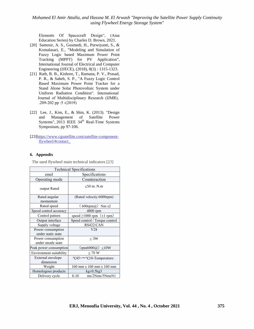
6. Appendix
The used flywheel main technical indicators [23]
ehtelutan y:htututauuelt
h.t y:htututauuelt
r:hsauulr .eCh devluhsatuuel
eauhC evu:vu 50 m. N.m
eauhC alrvnas
.e.hluv.
(eauhC whnetuuz:6333s:.)
eauhC t:hhC 2i.mt(@s:.633 )
y:hhC telusen attvsatz 4800 rpm
delusen :auuhsl speed ≥1000 rpm)±1 rpm(
rvu:vu uluhstath y:hhC telusen t eesrvh telusen
yv::nz wenuarh ey422tdSi
Power consumption
under static state
28V
Power consumption
under steady state 3W
rhaj :exhs teltv.:uuel 10W(@6333s:.)
flwusel.hlu tvuua.unuuz 70 W
fyuhslan hlwhne:h
Cu.hltuel eh.:hsauvsh: -13℃~+45℃
ghureu 160 mm x 160 mm x 160 mm
2e.enerevt :seCvtut 3jr53m5jr
ehnuwhsz tztnh 6-10 1i.tt2i.tt5i.t