in-building wireless solutions - bicsi · in-building wireless solutions ... high rise buildings...
TRANSCRIPT

®
In-Building Wireless Solutions
Bob Kostash • Channel Manager • June 28, 2012

IBW (In-Building Wireless)What IS It?
IB I B ildi
What Is It NOT?
It i NOT Wi Fi WiM• IB = In-Building.– Enhancement of Cellular and Public
Safety signals inside a building/structure.
• It is NOT Wi-Fi or WiMax• It is NOT a wireless LAN or wireless
Ethernet• Does NOT use Access Points (AP’s)
• Signal enhancement accomplished via a Distributed Antenna System or DAS.
• Does NOT use Access Points (AP s)• It is NOT tower-mounted equipment
and cable / apparatus, although some products are used in both IBW and
• Licensed band• Covers all carriers on one
infrastructure• Simple, scalable architecture – single
ptower application.
p , gto multi-band, multi-carrier installations
• Single floor, building, or entire campus

Buildings That May Require An IBW Solution
• Corporate Offices (Fortune 1000)• Multi-tenant High-Rise Office Buildingsg g• Universities• Hospitals• Manufacturing Facilitiesg• Upscale Hotels and High-Rise Condos• Casinos, Convention Centers• Stadiums• Fed/Local Government Facilities• ESPECIALLY New Construction (may have a DAS budget)

Building Issues That IBW Can AddressHigh-Rise Buildings
The building is acting as an RF shield.Fortified Construction, Highly tinted windows, lack of coverage in below grade floors, elevators, and center of building
Coverage Problems
g , , g
High Rise buildings (typically over 25 floors)Above cell site tower coverage footprint, or no dominant control signal (multiple towers equally “clear”)signal (multiple towers equally clear )
The building is blocked from the tower by other buildings.
The Cell Tower is too far away
Deep Cavernous Buildings
C
The Cell Tower is too far away.
Below Grade
Coverage Problems
Coverage Problems CoverageBelow GradeBelow GradeCoverage Problems Coverage
Problems

Leadership in Energy and Environmental Design (LEED)Design (LEED)
Low E-Glass•Low E glass coatings work by reflecting or absorbing IR light (heat energy). This same coating also reflects radio waves, causing significant in-building wireless gcoverage problems.
•Any building identified as y gseeking LEED certification will be using low E glass.low E glass.

Example
Royal Bank of Canada• 2 Towers (North and South)• 14000 Windows• 2500 Ounces of Gold
embedded in the glass

IBW Market Drivers: Commercial
• Ubiquitous cellular coverage is now expected in buildings
Car / Outdoors / Traveling / Home & Office / Everywhere
• Ubiquitous cellular coverage is now expected in buildings• >75% of mobile calls are originating or terminating indoors
(Verizon 2009)• 2005 survey- 55% of the respondents said they have dead
zones in their workplaceh i d h % f b ib l k• The same survey pointed out that 77% of subscribers look to
their carrier for a solution (but this is changing)• Higher frequency 3G/4G data services (WiMAX and LTE) areHigher frequency 3G/4G data services (WiMAX and LTE) are
making in-building coverage more important

Market Driver: Mobile Penetration Reaching 100%Mobile Penetration Reaching 100%
Mobile Subscribers
78
3456
Bill
ions
4G3G2G
0123 2G
2004 2005 2006 2007 2008 2009 2010 2011 2012 2013 2014
• The number of mobile subscribers passed the 5 billion bar in 2010 and is onThe number of mobile subscribers passed the 5 billion bar in 2010 and is on track to hit 6 billion between 2012 and 2013
• With the worldwide population now at 6.9 billion, it is very likely that mobile penetration will exceed the global population in the near future
Infonetics Research, 2G/3G Mobile Infrastructure Equipment Market Share and Forecasts 3Q10, December 2010

Market Driver: Data, Data, Data• Data growth: dramatic and non-
stop 3,600,000 4%5%8%
108% CAGR 2009–2014
• HSPA+ and LTE: predominant technologies for delivering high-speed data
8%
17%
nth
1,800,000
66%TB p
er M
on
02009 2010 2011 2012 2013 2014
0
Mobile VoIP Mobile Gaming Mobile P2P
Mobile Web/Data Mobile Video
Source: Cisco VNI Mobile, 2010

IBW Market Drivers: Public Safety
bli S f• Public Safety– In-building coverage taking on greater importance
Migration to 700/800 MHz means less signal penetration– Migration to 700/800 MHz means less signal penetration– Portable radios should support first-responders within
buildingsg– New ordinances and building codes are mandating
coverage

Is a Coverage System Required g y q• Wireless Service Provider (WSP) Commercial Services
– Are there less than 3 “BARS” on a phone?Are there less than 3 BARS on a phone?– Do people complain about poor cellular coverage indoors?– Do people need to stand next to a window to make a call?
h f ll ?– Does the owner want to guarantee full coverage?
bli f i ( li fi )• Public Safety Services (police, fire, rescue)– Does the city have a first-responder in-building coverage ordinance?– Do first responders complain about poor 2-way radio coverage?p p p y g– Is there coverage in the stairwells and elevators?– Do you have liability concerns?

In-Building Wireless – Problems Solved!• Neutral Host System
– Supports all W-WAN systems• Public Safety and commercial operators
– Negotiate wireless service from any operator
Coverage Problems
Negotiate wireless service from any operator
• Improve business level QoS – more bars
• Reduce liability risk through improved public safetyReduce liability risk through improved public safety
• Increase efficiency of mobile employees, customers, vendors
• A future-proof solution that will migrate as wireless technology evolves
C
A future proof solution that will migrate as wireless technology evolves
Coverage Problems
Coverage Problems
Coverage Problems Problems Coverage Problems

DAS System Configurationsy g• Passive DAS - Coax used to distribute RF signals
Only one active component; bi-directional amplifier (BDA) Ideal solution for smaller venues <150K ft2
Limited growth or expansion capability Limited growth or expansion capability Parallel systems required for carrier and public safety
• Active DAS - Adds RFFO conversion, fiber, and distributed amplifiers Scalable – Single to multi-band/operator installations C t ff ti lti i 150 000 ft Cost effective multi carrier coverage over 150,000 sq. ft. Flexible for growth and expansion One system for both Cellular Carriers and 700/800/900 Public Safety

PASSIVE DASPASSIVE DAS

Passive System Design – Small Venues
• 3 components in Passive system• 3 components in Passive system• Outdoor Antenna• Indoor Antenna• Small Bi-Directional Amplifier
• Ideal for spaces up to 25K sq. ft.• Generally, good for a Single
Service Provider• Typically, Dual Band (Cell andTypically, Dual Band (Cell and
PCS) support
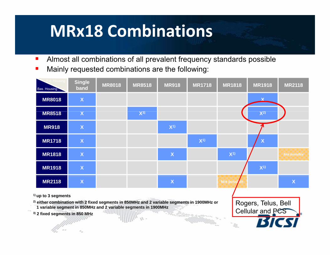
MRx18 Combinations Almost all combinations of all prevalent frequency standards possible Mainly requested combinations are the following:
Single band MR8018 MR8518 MR918 MR1718 MR1818 MR1918 MR2118
MR8018 X X
3) 2)
Bas. Housing
Ext. Housing
MR8518 X X3) X2)
MR918 X X1)
MR1718 X X1) X
MR1818 X X X1) Not possible
MR1918 X X1)
MR2118 X X Not possible X
1) up to 3 segments2) either combination with 2 fixed segments in 850MHz and 2 variable segments in 1900MHz or
1 variable segment in 850MHz and 2 variable segments in 1900MHzRogers, Telus, Bell
1 variable segment in 850MHz and 2 variable segments in 1900MHz3) 2 fixed segments in 850 MHz Cellular and PCS

Passive Solution Design – Larger Venues
Donor-Antenna(C ll 850)(Cell 850)
Node A Multi-Band(Cell, PCS, AWS)
Donor-Antenna(PCS 1900, AWS 1700/2100)
Ideal for spaces up to 150K sq ft• Ideal for spaces up to 150K sq. ft.• 3 components in Passive system
• Outdoor Antenna• Indoor Antenna• Larger Bi-Directional Amplifier
• Able to support Multiple Service Providers• Typically, Multi-Band (Cell and PCS, AWS,
PS UHF) supportPS UHF) support

Bi-Directional Amplifiers (BDA) / Repeaters
• Scalable: Upgradable to meet the continual evolution of new wireless standards & technologies
• Selective: Utilization of the latest advancements in technology to ensure independence from other radio transmission sites
lli fi bl h d i d f h• Intelligent: Reconfigurable to meet the dynamic needs of the ever changing wireless landscape
• Efficient: The industry’s most compact and energy efficient off-air,Efficient: The industry s most compact and energy efficient off air, Multi-Band repeater

Node A RF Modules for Commercial SpectrumSpectrum
700 MHzAF 727 ½ watt
698 – 716 & 776 – 787 / 728 – 757 MHzAF737 5 wattAF737 5 watt
800 MHz AF8037 5 watt 806 – 824 / 851 – 869 MHz
AF 8527 ½ watt850 MHz
AF 8527 ½ watt824 – 849 / 869 – 894 MHz
AF8537 5 watt
900 MHz AF 9037 5 watt 896 – 902 / 935 – 941 MHz
1900 MHzAF 1927 ½ watt
1850 – 1915 / 1930 – 1995 MHzAF 1937 5 watt
2100 MHzAF 1727 ½ watt
1710 – 1755 / 2110 – 2155 MHzAF 1737 5 watt

DAS RF Path Floor
4
Cellmax 1 Cellmax 2
Cellmax 1 Cellmax 2
Cellmax 3 Cellmax 4
Cellmax 3 Cellmax 4
Heliax CableHeliax CableION
Remote
Floor3
Cellmax 1 Cellmax 2
Cellmax 1 Cellmax 2
Cellmax 3 Cellmax 4
Cellmax 3 Cellmax 4SingleModeFiber
ION Remote
Floor2
FloorCellmax 1 Cellmax 2 Cellmax 3 Cellmax 4
Fiber
ION Remote
Floor1
O-DAS ION Master
ION Remote
CellmaxDonor Antenna
AIMOSO i d
Node-A Repeater
Base Station
Base Station
O-DAS ION Master Unit
Operations and Maintenance
Center
Base Station

Network Elements – Active Devices
Node A® Repeater/BDA- amplifies multiple frequency bands, and filters public safety channels (BDA = Bi-Directional Amplifier)
ION B Fib H d E d t th RF i lION-B® Fiber Head-End- converts the RF signal to RF-over-fiber (RFoF), which is then transmitted down single-mode fiber-optic cable to the fiber remote unit
7-Band Fiber Remote Unit- converts the RFoF transmission back to an RF signal, which is then transmitted down 50 Ohm Heliax® coax cable to the coverage antenna

Network Elements Network Elements –– Passive DevicesPassive Devices
Donor Antenna- picks-up the donor signal from the cellular or public safety tower
Donor Antenna Cable- delivers the RF signals from the donor antenna to the repeater/BDAp
Plenum Cable- carriers the RF signals from the repeater/BDA― or the fiber remote unit ― to therepeater/BDA or the fiber remote unit to the coverage antenna
Splitter- Splits the RF signals, which is then delivered to multiple inputs/elements
Omni Coverage Antenna – emits all of the RF signals to the coverage areasignals to the coverage area

Complete In-Building Wireless SolutionComplete In Building Wireless Solution Passive distribution on each floor with coax & antennas Active equipment amplifies and conditions all carrier and public safety signals Utilizes Coax FO conversion and fiber backbone distribution system Utilizes Coax FO conversion and fiber backbone distribution system Dynamic system provides future-proofing as frequency allocations change
WallOrganizer
HELIAX½ inch
CellMaxDonor
CellMaxIndoor
Antennas
CableAntenna
HELIAXCable
ION-BR t
SM FiberCable
ION-B
Remotes
Node-ARepeater
Master
CarrierBase
Station

DESIGN, INSTALLATION ANDDESIGN, INSTALLATION AND COMMISSIONING

Deployment Process Complexityp y p ySite Survey
Preliminary Design RF SurveyStatement of
Work
Detailed Pre-Construction Final DesignCarrier
Design SurveyFinal Design Approval
System Acceptance
Order Equipment
Installation Commissioning
Engage your CommScope Account Manager as soon as possible after identifying a prospective Customer

Who Will Do the Installation?
• Any one or any combination of the following can be involved in IBW implementations:in IBW implementations:– General Contractor– Electrical Contractor
( d bl )– CommScope Business Partner (structured cabling)– In-Building Wireless Integrator– CommScope Solution Business Partner– WSP
• Defining Scope of Work for each stakeholder is an important• Defining Scope of Work for each stakeholder is an important step in implementation; CommScope can help guide the process.

Thank You