in copyright - non-commercial use permitted rights ...46752/... · master’s thesis nr. 119 ......
TRANSCRIPT

Research Collection
Master Thesis
Hardware transactional memory and message passing
Author(s): Fuchs, Raphael
Publication Date: 2014
Permanent Link: https://doi.org/10.3929/ethz-a-010255349
Rights / License: In Copyright - Non-Commercial Use Permitted
This page was generated automatically upon download from the ETH Zurich Research Collection. For moreinformation please consult the Terms of use.
ETH Library

Master’s Thesis Nr. 119
Systems Group, Department of Computer Science, ETH Zurich
Hardware Transactional Memory and Message Passing
by
Raphael Fuchs
Supervised by
Prof. Dr. Timothy Roscoe, Dr. Antonios Kornilios Kourtis
September 19, 2014

Abstract
Message passing has gained increased adoption. It is an integral part of programminglanguages like Erlang and Go, the de-facto standard on large-scale clusters, and thebasic means of communication in the Barrelfish operating system.
This thesis focuses on point-to-point, inter-core message passing between two pro-cesses running in parallel and within a cache-coherency domain. State-of-the-artcommunication in such a scenario bypasses the kernel and relies on shared memoryfor message transfer, therefore providing high bandwidth communication. How-ever, low-latency is only achieved if the receiver is constantly polling, which wastesprocessor cycles that are better spent on application processing.
We describe a simple hardware mechanism, alert-on-update, that, inspired byhardware transactional memory, monitors multiple memory locations and triggers acontrol transfer upon modification. This mechanism enables the sender to notifythe receiver of a new message and, in turn, frees the receiver from constant polling.
We integrate alert-on-update into Barrelfish’s message passing framework anddescribe the support needed from the operating system. Using full-system simulation,the evaluation shows that our solution outperforms polling at regular intervals withmessage latencies up to several orders of magnitude lower and, on top of that,provides a cleaner programming construct.

Acknowledgments
First and foremost, I would like to thank Timothy Roscoe and Kornilios Kourtisfor their support and guidance. Their critical thinking and valuable input wereessential for the success of this thesis. It has been a pleasure working with you!Thanks also belongs to the rest of the Barrelfish team, for their input and feedbackespecially during our brainstorming sessions.
Additionally, I would like to thank Christine Zeller, Reto Achermann and JonasMoosheer for their comments and suggestions on an earlier draft of this thesis.
Contents
List of Figures 5
List of Tables 6
List of Listings 7
1 Introduction 8
2 Background 102.1 Hardware Transactional Memory . . . . . . . . . . . . . . . . . . . . 10
2.1.1 Intel Transactional Synchronization Extensions . . . . . . . . 102.1.2 AMD Advanced Synchronization Facility . . . . . . . . . . . 12
2.2 Barrelfish Operating System . . . . . . . . . . . . . . . . . . . . . . . 122.2.1 Overview . . . . . . . . . . . . . . . . . . . . . . . . . . . . . 122.2.2 Dispatchers and User-level Scheduler . . . . . . . . . . . . . . 132.2.3 User-level Message Passing (UMP) . . . . . . . . . . . . . . . 142.2.4 Flounder . . . . . . . . . . . . . . . . . . . . . . . . . . . . . 14
3 Using Intel TSX to Accelerate Message Passing 163.1 RTM Performance Analysis . . . . . . . . . . . . . . . . . . . . . . . 16
3.1.1 Setup and Commit Overhead . . . . . . . . . . . . . . . . . . 173.1.2 Abort Overhead . . . . . . . . . . . . . . . . . . . . . . . . . 173.1.3 Setup, Commit and Abort Overhead Scaling . . . . . . . . . 183.1.4 Time Limit . . . . . . . . . . . . . . . . . . . . . . . . . . . . 20
3.2 Abort Handler for Message Notification . . . . . . . . . . . . . . . . 213.3 Helper Threading and RTM for Message Passing . . . . . . . . . . . 233.4 n : 1 communication channels . . . . . . . . . . . . . . . . . . . . . . 263.5 Conclusion . . . . . . . . . . . . . . . . . . . . . . . . . . . . . . . . 27
4 Using Alert-on-Update to Accelerate Message Passing 284.1 Alert-on-Update ISA Extension . . . . . . . . . . . . . . . . . . . . . 28
4.1.1 Enabling and Disabling Alerts . . . . . . . . . . . . . . . . . 294.1.2 Modify Set of Monitored Memory Locations . . . . . . . . . . 29
3
4.1.3 Alert . . . . . . . . . . . . . . . . . . . . . . . . . . . . . . . . 304.1.4 Implicit Disabling of Alerts . . . . . . . . . . . . . . . . . . . 304.1.5 Spurious Alerts . . . . . . . . . . . . . . . . . . . . . . . . . . 31
4.2 Message Passing Without Polling . . . . . . . . . . . . . . . . . . . . 314.2.1 Monitor Message Channel . . . . . . . . . . . . . . . . . . . . 324.2.2 Dedicated Memory Region for Notifications . . . . . . . . . . 32
4.3 Barrelfish Application Programmer API . . . . . . . . . . . . . . . . 33
5 Implementation 365.1 Alert-on-Update in Gem5 . . . . . . . . . . . . . . . . . . . . . . . . 365.2 Barrelfish Implementation . . . . . . . . . . . . . . . . . . . . . . . . 40
5.2.1 Monitoring UMP Channels . . . . . . . . . . . . . . . . . . . 405.2.2 Alert - Step-by-Step . . . . . . . . . . . . . . . . . . . . . . . 405.2.3 TLA+ Model and Model Checking . . . . . . . . . . . . . . . 435.2.4 Scheduler Activations and Why Using Alerts in Linux is Hard 45
6 Evaluation 476.1 Alerts versus Tight Polling . . . . . . . . . . . . . . . . . . . . . . . 476.2 Alerts versus Polling at Different Polling Frequencies . . . . . . . . . 496.3 Alerts versus Polling with Multiple UMP Channels . . . . . . . . . . 51
7 Related Work 53
8 Conclusion and Future Work 548.1 Directions for Future Work . . . . . . . . . . . . . . . . . . . . . . . 54
8.1.1 Alert-on-Update and Fast Mutexes . . . . . . . . . . . . . . . 548.1.2 Alert-on-Update and Hardware Transactional Memory Co-
design . . . . . . . . . . . . . . . . . . . . . . . . . . . . . . . 55
A Changes to the Barrelfish Operating System 56A.1 Timers and Timer Interrupts . . . . . . . . . . . . . . . . . . . . . . 56A.2 ARM ABI . . . . . . . . . . . . . . . . . . . . . . . . . . . . . . . . . 57
B TLA+ Specification 59
Bibliography 74
4
List of Figures
2.1 Barrelfish OS structure on a four core ARMv7-A system. . . . . . . 122.2 One dispatcher and three user-level threads, each with their associated
stacks and memory areas to store the register state when they arenot running. . . . . . . . . . . . . . . . . . . . . . . . . . . . . . . . . 13
3.1 Intel RTM Commit and Abort Scaling . . . . . . . . . . . . . . . . . 183.2 Intel RTM Commit and Abort Scaling with Barrier . . . . . . . . . . 203.3 Hyper-Threading and nop loop . . . . . . . . . . . . . . . . . . . . . 25
4.1 Alert handler register state . . . . . . . . . . . . . . . . . . . . . . . 30
5.1 Extended MOESI cache-coherency protocol with four new alert states:AM, AO, AE, AS. . . . . . . . . . . . . . . . . . . . . . . . . . . . . 38
5.2 Layout of memory structure to support alerts . . . . . . . . . . . . . 415.3 Example two states that relate by the ThreadYield action. . . . . . . 44
6.1 Message latency breakdown. . . . . . . . . . . . . . . . . . . . . . . . 486.2 Application overhead for 1, 10 and 100 UMP channels . . . . . . . . 51
5

List of Tables
4.1 Alert-on-update ISA extension instructions. . . . . . . . . . . . . . . 30
5.1 Encoding of AOU instructions using co-processor 3 . . . . . . . . . . 37
6.1 Gem5 simulation parameters. . . . . . . . . . . . . . . . . . . . . . . 476.2 Benchmark results from compute-intensive task that also receives
UMP messages using 1 channel. . . . . . . . . . . . . . . . . . . . . . 49
6

List of Listings
2.1 Code pattern for Restricted Transactional Memory (RTM). . . . . . 113.1 Microbenchmark to measure base cost of setting up and committing
a transaction. An empty transaction is executed one million times.The base cost of setting up and committing a transaction is computedby dividing the total execution time by the number of iterations. . . 17
3.2 Microbenchmark to measure the time until a transaction containingan infinite nop loop gets aborted. . . . . . . . . . . . . . . . . . . . . 20
4.1 Enable monitoring for waitset. . . . . . . . . . . . . . . . . . . . . . 334.2 Disable monitoring for waitset. . . . . . . . . . . . . . . . . . . . . . 344.3 Test whether waitset is monitored. . . . . . . . . . . . . . . . . . . . 344.4 Event dispatch function for a monitored waitset. . . . . . . . . . . . 34
7
Chapter 1
Introduction
Message passing, as a communication and synchronization mechanism, has gainedincreased adoption. It is used as the only form of communication between processesin Erlang [12, Chapter 5] and is an integral part of the Go programming language.The user guide Effective Go postulates: “Do not communicate by sharing memory;instead, share memory by communicating.” [1] Moreover, on large-scale clusters,MPI [36], a portable message passing system, is the programming model of choice [41].
In the area of operating systems, favoring message passing over shared memory hasbeen an important design decision for the Barrelfish [14] operating system. Andin the Linux community, there is an ongoing effort to replace D-Bus with a moreefficient inter-process communication system [20].
In this thesis, we restrict ourselves to inter-core message passing within a cache-coherency domain. State-of-the-art message passing between two processes in sucha system bypasses the kernel altogether and relies on shared memory for messagetransfer [15]. Note that while the implementation of the message passing facilityemploys shared memory, it is different from a programming model where processesor threads directly share an address space. With message passing, all communicationis explicit and the processes do not rely on shared memory, only on the messagepassing mechanism. They do not need to be adapted if they were run on two coresthat do not share memory, as long as a form of message passing is available.
User-level message passing (UMP) of Barrelfish demonstrates that message passingin such a system can provide high bandwidth. By exploiting knowledge of thecache-coherency protocol, cache-line-sized messages can be transferred directly fromthe sender’s cache to the receiver’s without going through main memory.
The receiver uses polling to detect the arrival of new messages. While a tight pollingloop on the receiver results in low-latency message delivery, it is wasteful and oftennot feasible to poll for an extended amount of time because other computationneeds to be done.
8

What really is missing is an efficient way for the sender to notify the receiver thatthere is a new message. This is the problem this thesis tackles. While notificationscan be sent by involving the kernel and using inter-processor interrupts, such anotification scheme would be very heavy-weight compared to the size of the message.Our goal is to provide a notification mechanism that is light-weight and workscompletely in user space.
To arrive at our goal, we will incorporate ideas from hardware transactional memory.In particular, hardware transactional memory systems like Intel’s TransactionalSynchronization Extensions (TSX) allow to monitor a set of cache lines and triggera control transfer if any of them changes. We will use such a mechanism as thebasis of our message notification scheme.
After introducing concepts and terminology used throughout this thesis in Chapter 2,Chapter 3 will analyze to what extend Intel’s TSX can be used to accelerate messagepassing. We will find that while the mechanisms provided by TSX would be usefulfor message notification, it cannot, in its current form, be used for such a purpose.Consequently, Chapter 4 describes a simple hardware mechanism, alert-on-update,that carries over features from hardware transactional memory systems but has anAPI suitable for message notification. The implementation of the alert-on-updatehardware extension in a CPU simulator as well as how we use this extension formessage passing in Barrelfish is presented in Chapter 5. Chapter 6 evaluates theeffectiveness of the hardware feature and the software implementation, whereasChapter 7 surveys related work. Finally, Chapter 8 concludes and gives directionsfor future work.
Appendix A describes changes made to Barrelfish that are unrelated to messagepassing but were nevertheless necessary to get a working system. Appendix Bcontains a formal specification of our implementation in TLA+.
9
Chapter 2
Background
This chapter provides background information on two topics used throughout thethesis. Section 2.1 introduces hardware transactional memory and in particularIntel’s TSX while Section 2.2 gives an overview of the Barrelfish operating system.
2.1 Hardware Transactional Memory
Recently, several implementations of hardware transactional memory systems haveappeared. The processor used in the Blue Gene/Q supercomputer has hardwaresupport for transactional memory [25, Section 2.15] and the Power ISA Version2.07 [26, Book II, Chapter 5] features it. Moreover Intel’s Haswell processors supportit [28, Chapter 15] and AMD proposed their own version of transactional memory [4].
In this section, we give a brief overview of Intel’s Transactional SynchronizationExtensions (TSX) in Section 2.1.1, and in Section 2.1.2 we describe how AMD’sproposed Advanced Synchronization Facility (ASF) differs. The interested readerwill find a more in-depth discussion of hardware transactional memory systems,both industry designs and research proposals, in Harris et al. [23, Chapter 5].
2.1.1 Intel Transactional Synchronization Extensions
Intel’s TSX [27, Chapter 12] [28, Chapter 15] [33] provides two separate programminginterfaces. The first, Hardware Lock Elision (HLE), is based on work by Rajwarand Goodman [37] on speculative lock elision. The high-level idea of HLE is tooptimistically execute critical sections without taking the lock, thereby exploitingdynamic parallelism, and fallback to acquiring the lock only if a conflict arises duringactual execution.
10

The interface consists of two new instruction prefixes xaquire and xrelease.xaquire prefixes the assembly instruction that acquires the lock while xrelease
prefixes the corresponding lock release instruction. These prefixes are forwardcompatible: older processors that do not support HLE simply ignore these twoprefixes, therefore always taking the fall back path of acquiring the lock.
The second interface is called Restricted Transactional Memory (RTM) and allowsto execute an instruction sequence transactionally. Unlike HLE, this interface is notforward compatible, it generates an exception if used on an unsupported CPU.
Listing 2.1 shows the common code pattern used with RTM. Transactional executionis started with the xbegin instruction. It takes as single argument the address of thefallback path in case the transaction aborts. xend marks the end of the transactionalregion. If there are no conflicts, xend commits all changes to memory atomically.Otherwise, the transaction aborts, any updates to memory since the start of thetransaction are discarded, and execution continues at the fallback address.
xbegin abort
# executed transactionally
xend
jmp continue
abort:
# fallback path
continue:
Listing 2.1: Code pattern for Restricted Transactional Memory (RTM).
In order to detect conflicting accesses between a transaction executing on oneprocessor and all other processors, the hardware tracks the read- and write-set foreach transaction. As the names imply, the read-set contains all memory locations thetransaction read while the write-set contains all locations written. A data conflictoccurs if another processor reads from a memory location in the read-set of thetransaction or writes to a location in the read- or write-set of the transaction.
Data conflicts are a primary reason of aborts. Transactions also abort if theycontain one of the many unsupported instructions, examples include the pause
instructions, ring transitions (sysenter, syscall), legacy I/O operations (in, our),monitor and mwait, etc. [28, Section 15.3.8]. There are many more reasons why atransaction might abort, like limited architectural resources to buffer the changesmade by an uncommitted transaction or interrupts happening during transactionalexecution [27, Section 12.2.3]. Transactions can also be explicitly aborted using thexabort instruction.
If a transaction aborts, all changes made to memory and registers are discarded andexecution continues at the fallback address. The eax register contains informationabout the abort, why it happened and whether a retry might succeed. All otherregisters contain the value they had at the time the transaction was started withxbegin.
11

2.1.2 AMD Advanced Synchronization Facility
AMD’s ASF [4] is similar to Intel’s TSX except for two major differences. First,it allows for loads and stores to bypass the transactional mechanism. With TSX,all loads and stores within a transaction are implicitly transactional. ASF allowsloads to optionally not be added to the read-set and for stores to optionally takeimmediate effect. Both types of loads and stores can occur within a transaction andthey are distinguished by whether or not the x86 mov instruction carries the lock
prefix.
Second, the register state is not automatically checkpointed when the transactionstarts and restored when an abort is triggered. Instead, software is responsible forsaving and restoring them. As a result, the registers at the time execution wasinterrupted by the abort are available to the abort handler except, for rax, rip,rsp and rflags, which are overwritten.
2.2 Barrelfish Operating System
2.2.1 Overview
Barrelfish is a research operating system developed by ETH Zurich. It is structuredas a multikernel [14] and a high-level overview of the system architecture is depictedin Figure 2.1.
HardwareARMv7-A
coreARMv7-A
coreARMv7-A
coreARMv7-A
core
Kernel space CPUDriver
CPUDriver
CPUDriver
CPUDriver
User space MonitorMonitor Monitor Monitor
Domain 1Dispatcher
Domain 2Dispatcher
Domain 3Dispatcher Dispatcher
Figure 2.1: Barrelfish OS structure on a four core ARMv7-A system.
The figure shows a four core ARMv7-A CPU running Barrelfish. Each core runsits own copy of the kernel, called CPU driver, and they do not share any state.Like in a microkernel, the CPU driver is only responsible for enforcing protection,
12

basic scheduling and fast message passing between applications running on thesame core. In particular, device drivers, filesystems and the networking stack areimplemented in user space. Additionally, each core runs the monitor process in userspace. Collectively, they are part of the trusted computing base and coordinatesystem-wide state using message passing.
Processes are called application domains or just domains. While the CPU driverand the monitor do not rely on shared memory but use message passing for commu-nication, applications might use shared address spaces and span multiple cores. Foreach core the application runs on, there exists an object called dispatcher, which isthe entity the local CPU driver schedules.
2.2.2 Dispatchers and User-level Scheduler
Barrelfish uses scheduler activations [6]. The dispatcher is upcalled by the kernel,which, in turn, runs the user-level scheduler to decide which thread to resume. Whilethe user-level scheduler runs, further upcalls are disabled. If the kernel interrupts thedomain while upcalls are disabled, it later resumes the domain instead of upcallingit.
Dispatcher
enabledsave area
disabledsave area
stack
disabledflag
Thread 1
registersave area
stack
Thread 2
registersave area
stack
Thread 3
registersave area
stack
Domain
Figure 2.2: One dispatcher and three user-level threads, each with their associated stacksand memory areas to store the register state when they are not running.
Figure 2.2 shows a single dispatcher and three user-level threads together with theirassociated state. Each thread has a stack and a memory region used to store theregister state if it is not running.
The kernel only schedules the dispatcher and has no knowledge of user-level threads.Consequently, when the kernel interrupts an application domain, it cannot store the
13
register state directly to the thread save area. Instead, the register state is stored inthe enabled or disabled area of the dispatcher, depending on whether upcalls wereenabled or disabled at the time the interrupt happened. If upcalls were disabled,the kernel later resumes the dispatcher with the register state from the disabledarea. If they were enabled, the dispatcher is upcalled and starts executing on itsown stack. It has knowledge of the user-level threads and knows which one was lastrun and can copy the register state from the enabled area to the save area of thecorresponding thread before scheduling another thread.
2.2.3 User-level Message Passing (UMP)
For inter-core communication, Barrelfish uses a variant of URPC [15]: a sharedmemory region is used as communication channel between one sender and a singlereceiver. After a setup phase, all communication happens completely in user spacewithout any kernel involvement. Thus, it is appropriately named user-level messagepassing (UMP).
The shared memory region is organized into cache-line-sized messages. Sending amessage simply consists of writing it to the shared region while the receiver usespolling to detect a new message.
UMP provides a high bandwidth messaging channel. On a system with a MOESIcache coherency protocol the message is directly transferred from the sender’s cacheto the receiver’s without going through main memory. In the common case, only twobus transactions are necessary: one when the sender starts writing and invalidatesthe cache line on the receiver’s side and one when the sender polls. When the latterhappens, the modified cache line transitions to the Owned state on the sender andthe receiver cache fetches it there [14].
UMP communication can be low latency but only if the receiver continuously polls.Otherwise, the latency is directly correlated to the polling frequency.
2.2.4 Flounder
Apart from UMP, Barrelfish provides other means of message passing, for examplelocal message passing (LMP) between domains running on the same core.
On top of these low-level and fixed-message-sized communication channels, Barrelfishfeatures a higher-level messaging infrastructure called Flounder [13] which providesa common interface regardless of the type of message passing used. Additionally, ithandles marshalling and demarshalling between application messages and fixed-sizedinterconnect messages.
The runtime support for message passing comes in the form of waitsets. A waitsetbundles multiple channel endpoints and presents activity on the channel, for examplean newly arrived message, as events. Internally, the waitset categorizes the channels
14
into three groups: pending, polled and idle. Channels in the pending group have atleast one pending event that is ready to be handled, whereas channels in the idlegroup have none. For channels in the polled group, we do not know whether or notthere is a pending message and need to poll them regularly.
A UMP channel is part of either the polled or the pending group of a waitset. If wealready know that there is a pending message, it is in the pending list, otherwise itis in the polled list.
To handle events, the function event_dispatch is called on a waitset, commonlyinside an infinite loop. On each invocation, the following steps are performed. First,it is checked whether there are channels in the pending group. If there are, the nextevent from one of them is handled. If there are no pending channels, it is checkedwhether any of the channels in the polled queue has an event. If that is the case,the event is handled, otherwise, the function blocks.
15

Chapter 3
Using Intel TSX toAccelerate Message Passing
In this chapter, we analyze to what extent Intel TSX can be used to acceleratemessage passing. Section 3.1 evaluates the performance characteristics of TSX. InSection 3.2 we describe our initial idea of using the control transfer triggered by anabort as a notification mechanism for message passing and identify why the TSXabort handler cannot be used for notification. The two sections that follow, describealternative ways how TSX might be employed to accelerate message passing.
3.1 RTM Performance Analysis
In this section we analyze the performance of TSX and in particular RTM by a seriesof microbenchmarks. All measurements were done on an Intel Core i7-4770 runningat 3.40GHz. Frequency scaling was effectively disabled by setting the minimumand maximum frequency to 3.40GHz. For the benchmark, Hyper-Threading wasdisabled in the BIOS and Turbo Boost was turned off by setting the value in/sys/devices/system/cpu/intel_pstate/no_turbo to 1. The system softwareconsisted of Linux kernel 3.14.2, glibc 2.19 and gcc 4.9. All benchmarks use a singlethread which was pinned to a specific processor core and the rdtscp instruction wasused to measure execution time.
The microbenchmarks answer the following questions:
• What is the overhead of setting up and committing a transaction? (Sec-tion 3.1.1)
• What is the overhead of aborting a transaction? (Section 3.1.2)
16

• How does the cost of setting up, committing and aborting a transaction scalewith increased transaction size? (Section 3.1.3)
• Is there a time limit for transactional execution? (Section 3.1.4)
3.1.1 Setup and Commit Overhead
The first microbenchmark measures the base cost of setting up and committing atransaction by measuring the execution time of an empty transaction. Listing 3.1shows the code used for the microbenchmark. To amortize the cost of reading thetime stamp counter, the execution time for multiple transactions (one million inour case) is measured and the total execution time is divided by the number oftransactions executed to arrive at the base cost of setting up and committing asingle transaction. Because the transactional memory intrinsics (_xbegin(), _xend()and _xabort()) for gcc result in a suboptimal code pattern, inline assembly wasused instead.
1 // read time stamp counter
2 for (int i = 0; i < 1000000; i++) {
3 __asm__ __volatile__("xbegin 1f \n\t"
4 "xend \n\t"
5 "1:");
6 }
7 // read time stamp counter
Listing 3.1: Microbenchmark to measure base cost of setting up and committing atransaction. An empty transaction is executed one million times. The basecost of setting up and committing a transaction is computed by dividing thetotal execution time by the number of iterations.
The above described microbenchmark was run ten times. The average overhead ofsetting up and committing a transaction was 47.89 cycles with a standard deviationof 0.06 cycles.
3.1.2 Abort Overhead
The next benchmark measures the overhead of aborting a transaction. To this end,we measure the execution time of a transaction that contains as its only instructionan explicit abort. The only difference between this benchmark and the one shownin Listing 3.1 is that between lines 3 and 4 an explicit xabort 0xff is inserted.
The benchmark was again run ten times resulting in an average time of 155.22cycles to setup and abort a transaction, with a standard deviation of 0.29 cycles.We assume that the abort is significantly slower than the commit because on anabort, the register state from the time the transaction started must be restored andthere is a control transfer to the address of the abort handler.
17

3.1.3 Setup, Commit and Abort Overhead Scaling
Having investigated the execution time of an empty transaction as well as thecost of immediately aborting a transaction, this section looks into the overhead ofcommitting or aborting a transaction of increasing size and compares it to executingthe same instruction sequence non-transactionally.
The benchmark explores transaction sizes, measured in number of cache linesmodified, between 0 and 100. A transaction of size x writes a 64 bit magic numberto the first cache line, then writes the same 64 bit magic number to the neighboringcache line and so on, until x cache lines are modified. Since the same magic numberis written to all cache lines, there is no dependency between the writes.
The execution time of each transaction is timed individually and the cache iscleared between measurements. For each size and each mode (non-transactional,transactional commit, transactional abort) 10’000 measurements are averaged. Theresulting graph is depicted in Figure 3.1.
0
500
1000
1500
2000
2500
3000
0 20 40 60 80 100
Late
ncy [cycle
s]
Number of cache lines written
Transactional Commit and Abort Scaling (cold cache)
non-transactionaltransactional commit
transactional abort
Figure 3.1: Execution times for modifying an increasing number of adjacent cache linesin three different scenarios. The first performs the modification outside of atransaction (non-transactional), the second within a transaction that commits(transactional commit) and the third within a transaction that explicitlyaborts after all modifications have been done (transactional abort).
The figure shows that in case the cache lines are modified within a committingtransaction, the execution time increases linearly with the size of the transaction.In the non-transactional and transactional abort case, the execution time is nearlyconstant for transaction sizes between 0 and 49 cache lines, followed by a sharp rise.Afterwards, the execution time increases linearly with the size of the transaction.
18

Since the slope for transactions larger that 50 cache lines is the same for a committingtransaction and for the non-transactional case, there is a constant overhead ofcommitting a transaction. Likewise, the slope for an aborting transaction andexecution of the instruction sequence non-transactional is the same. Therefore, theexecution overhead of aborting does not depend on the size of the transaction.
The near constant execution time for the non-transactional case can be explaineddue to the effect of store buffers. In a nutshell, a store buffer is a small cache thatsits between the CPU and its associated cache and holds outstanding writes untilthe corresponding cache lines arrive [35] [27, Section 2.1]. In the benchmark, weread the time stamp counter, write a series of cache lines and read the time stampcounter again. The modifications to the cache lines are kept in the store buffer untilthe cache lines arrive from main memory, which takes some hundred cycles due tothe cache being cleared before the measurement. Reading the time stamp counterwith rdtscp, however, does only wait until the modifications are recorded in thestore buffer and not for the store buffer to completely drain. For transaction sizessmaller than 49 cache lines, the modifications fit in the store buffer which results ina near constant execution time. Larger transactions fill up the store buffer, thenstall after each write, waiting for an entry in the store buffer to become available.Haswell’s store buffer has 42 entries [27, Section 2.1.4.1]. The sharp increase inexecution time happens at 49 modified cache lines. The latter is larger since whilethe store buffer is filled, some entries are already written back to cache makingspace for more entries.
The execution time in case we abort the transaction has a similar shape and can beexplained by the same argument. However, in case we commit the transaction theexecution time increases linearly even for small transactions, which can be explainedby the way transactions are committed. During commit, at the latest, data conflictsmust be detected. Since the current implementation of TSX tracks the read- andwrite-sets used for data conflict detection in the first-level cache [27, Section 12.1.1],all outstanding entries in the load and store buffer must arrive in the cache beforethe commit can happen. The draining of the load and store buffer during commitcauses the execution time for a committing transaction to increase linearly regardlessof transaction size.
To verify our hypothesis that the near constant execution time is due to the storebuffer, we repeated the previous experiment but forced a drain of the load andstore buffer before reading the time stamp counter the second time in the non-transactional case as well as before the xabort in the aborting case. The drain wasforced by using the mfence instruction. Figure 3.2 depicts the resulting graph, whichclearly shows that for all three scenarios there is a linear increase in execution time.
19

0
500
1000
1500
2000
2500
3000
0 20 40 60 80 100
Late
ncy [cycle
s]
Number of cache lines written
Transactional Commit and Abort Scaling (cold cache)
non-transactional with barriertransactional commit
transactional abort with barrier
Figure 3.2: Same experiment as in Figure 3.1, except that the load- and store buffersare explicitly drained in the non-transactional and aborting transaction case.
3.1.4 Time Limit
In this last microbenchmark, shown in Listing 3.2, we investigate whether or notthere is a time limit for transactional execution. The benchmark starts by readingthe time stamp counter and entering transactional execution. The body of thetransaction contains an infinite nop loop, therefore the end of the transaction (xend) isnever reached. Instead, the execution is trapped in the nop loop until the transactiongets aborted, at which point the time stamp counter is read again and the executiontime is computed.
for (int i = 0; i < 1000000; i++) {
// read time stamp counter
__asm__ __volatile__ ("xbegin 2f \n\t"
"1: \n\t"
"nop \n\t"
"jmp 1b \n\t"
"xend \n\t"
"2:");
// read time stamp counter
// compute and store execution time
}
Listing 3.2: Microbenchmark to measure the time until a transaction containing aninfinite nop loop gets aborted.
Taking one million samples, the average execution time before the transactiongot aborted was 3.16 ms (10’752’920 cycles) with a standard deviation of 0.74 ms
20

(2’499’796 cycles). Since the average execution time lies in the range of the timerinterrupts of the Linux kernel, we conclude that there is no time limit and thetransactions in our experiment only get aborted due to timer and other kinds ofinterrupts.
To conclude the performance analysis, we answer the questions posed at the beginningof the section. The overhead of setting up and committing a RTM transactionis 48 cycles, whereas the overhead of setting up and aborting is 155 cycles. Bothoverheads are constant and do not depend on the size of the transaction. Moreover,there is no time limit for a transaction.
Our results match the findings by Ritson and Barnes [38] in a similar performancestudy of RTM. They also compared using a transaction instead of multiple compare-and-swap instructions and found that using a transaction that modified two wordshas the same performance as using two compare-and-swap instructions. If only oneword is modified, compare-and-swap is faster whereas transactions are faster if morethan two words are modified.
3.2 Abort Handler for Message Notification
RTM provides the means to detect when a set of cache lines get modified and allowsexecution to continue at a predefined address in such an event. In this section,we will argue why such a mechanism is useful not only for hardware transactionalmemory but also for user-level notification and message passing.
At a high-level, user-level message passing between two cores, for example asimplemented in the Barrelfish operating system [31] [13], employs a shared memoryregion for communication. One of the cores writes to the shared location whereasthe other regularly polls for new messages. Polling, however, is wasteful, especiallyif low-latency message delivery is required and therefore a short polling intervalis used. A much better alternative would be for the sending core to inform thereceiving end that a new message is ready. Ideally, sending such a notification wouldbe done entirely in user space without going through the kernel, because traversingthe user-kernel boundary twice incurs a significant overhead.
Such a user-level notification and interrupt mechanism, in which a user-level processrunning on one core sends a notification to a process running on another core, which,in turn, transfers control to a notification handler and once finished continues whereit left of, is currently not implementable without going through the kernel. However,the mechanism provided by RTM of detecting modifications of cache lines andtriggering a control transfer almost allows for user-level notifications. Subsequently,we will describe how user-level notification could almost be implemented with RTMand then describe what is lacking to make it actually work.
To illustrate how user-level notification could almost be implemented, let us assumethat a thread running on core 0 wants to notify a thread running on core 1. A memory
21

region shared between both threads is used for communicating the notification andsending the notification simply consists of writing a value, for example 1, to theshared memory region. The novelty lies in the way the notification is received.Instead of polling the shared memory location regularly, the receiver registers anotification handler during initialization which is invoked when a notification isreceived. Registering the notification handler involves starting a transaction withxbegin handler, where handler is the address of the user-level notification handler.Then it transactionally reads the shared memory location, thereby adding it tothe read-set of the transaction. Without completing the transaction with xend,execution continues as normal. All memory operations, except the initial readingof the shared memory location, are done non-transactional, i.e. although they arewithin a transaction, they are not added to the read- or write-set of the transactionand therefore not used for conflict detection and not rolled-back during an abort.Once core 0 sends the notification by writing 1 to the shared memory location,core 1 aborts the transaction because a cache line in the transactions read-set wasmodified, and execution continues at the specified handler address. The notificationhandler processes the notification, re-registers the notification handler, restores theexecution context before it was interrupted and jumps back to the point where itleft off before receiving the notification.
The above described approach for user-level notification can also be applied to user-level message passing where the sender, instead of writing just the value 1, writesthe actual message to the shared memory buffer. The receiver gets notified withoutpolling that a message arrived and can handle the message right away or record thata message arrived. This approach is not limited to a single message channel. Thereceiver can monitor any number of channels by adding the corresponding memorylocation to its read-set during setup. This provides a powerful mechanism to waitfor a message on any number of channels without actually having to poll.
While RTM features a mechanism to detect changes in any number of cache-lines,the above described approach does not work with RTM for several reasons. First,our approach requires that once the notification or message handler is registered,transactional execution continues but references and modifications to memorylocations are non-transactional. Intel TSX does not provide such a feature. Allmemory references between xbegin and xend are implicitly transactional and allreferences outside of a transaction are non-transactional. There are, however,hardware transactional memory systems that support such a feature, for exampleAMD’s proposed Advanced Synchronization Facility [4].
Second, if a RTM transaction gets aborted, the execution context, e.g. register con-tent, is not retained. Instead, the register state at the point the transaction startedis restored. Since the execution context where normal execution was interruptedis not available in the notification handler, there is not way to continue executionthere. The only state which is available is the instruction pointer at which thetransaction got aborted. It is not available by default but can be made available byenabling Precise Event Based Sampling (PEBS) [30, Section 18.11.5.1]. However,
22

enabling PEBS is only possible from ring 0 and the mechanism incurs a significantoverhead: the abort induces a PEBS interrupt, which in turn writes the instructionpointer to a buffer.
In summary, RTM provides the basic mechanism to detect changes in any number ofcache lines and allows execution to continue at a specified address. Nevertheless, thecurrent implementation of RTM has several shortcomings rendering it impossible toimplement user-level notification or message passing without polling in a straight-forward way. Next, we explore two alternative ways to accelerate message passingusing TSX. These two alternatives do not try to employ notifications in lieu ofpolling but instead aim at reducing the polling time.
3.3 Helper Threading and RTM for Message Pass-ing
Applications in operating systems like Barrelfish [14] that use message passing as thebasic means of communications quickly end up polling a large number of messagechannels, where polling latency increases linearly with the number of channels.Instead of replacing polling with a notification mechanism as proposed in the lastsection, an alternative way to accelerate message passing is to reduce the pollinglatency from linearly dependent on the number of channels to constant. Such adecrease in polling time can be achieved using a concept commonly referred to ashelper threading.
The idea of helper threading is to accelerate a primary thread by using an additionalexecution context (also called logical core, hyperthread or hardware thread). Thisis often used in combination with Simultaneous Multithreading (SMT) whereboth the primary and helper thread run on the same core but on two differenthardware threads. Helper threading has been used previously for speculativeprecomputation [19] [43], where the helper thread prefetches data for the primarythread thereby reducing the number of cache misses on the critical path. It has alsobe used to overlap communication and computation [22].
In our case, the helper thread is used to poll all the channels the application isinterested in and summarizes the readiness in a single word. In a simple scheme, thisword contains a boolean flag indicating whether any channel is ready. Alternatively,the summary word could contain one bit for each channel polled, precisely indicatingwhich channels, if any, are ready. The primary thread still polls, but before pollingall the different channels, it checks the summary word to see if any channel is readyand only polls if some channels are ready. In case no channel is ready, this resultsin constant instead of linear overhead.
The helper thread performs the following steps. First, it starts transactionalexecution with xbegin handler. Then it reads all the message channels the primarythread is currently polling. The primary thread communicates the list of message
23

channels by writing it to a shared memory location. Next, the helper thread waitsfor the transaction to abort while doing nothing. This is implemented with aninfinite loop of nop instructions. Once the transaction aborts, the abort handlerchecks whether any of the channels is actually ready (it could have been a spuriousabort for example because a cache line from the read-set was evicted from the cache)and writes the summary word accordingly. Now, the same steps are repeated adinfinitum.
As an optimization and to reduce the number of spurious aborts due to interrupts,the helper thread could be executed in ring 0 as a minimal helper kernel with allinterrupts disabled. Depending on whether the application would benefit fromsuch a helper kernel, it could dynamically be enabled or disabled. Recent researchdemonstrated that dynamically booting new or other versions of kernels [45] isfeasible.
Whether or not the helper kernel accelerates the main application depends on whetherthe increase in performance due to faster polling outweighs the two disadvantages.The first disadvantage is having only one hardware thread per core available forthe main application instead of two. The second is the possible slowdown of theapplication resulting from executing a nop loop on the second hardware thread.
We expected that executing a nop loop on one hardware thread does not significantlyslow down the other execution context running on the same core, and performed aseries of measurement to verify or invalidate our hypothesis. Except when statedotherwise, the same system, software, and settings were used as for the experimentsin Section 3.1.
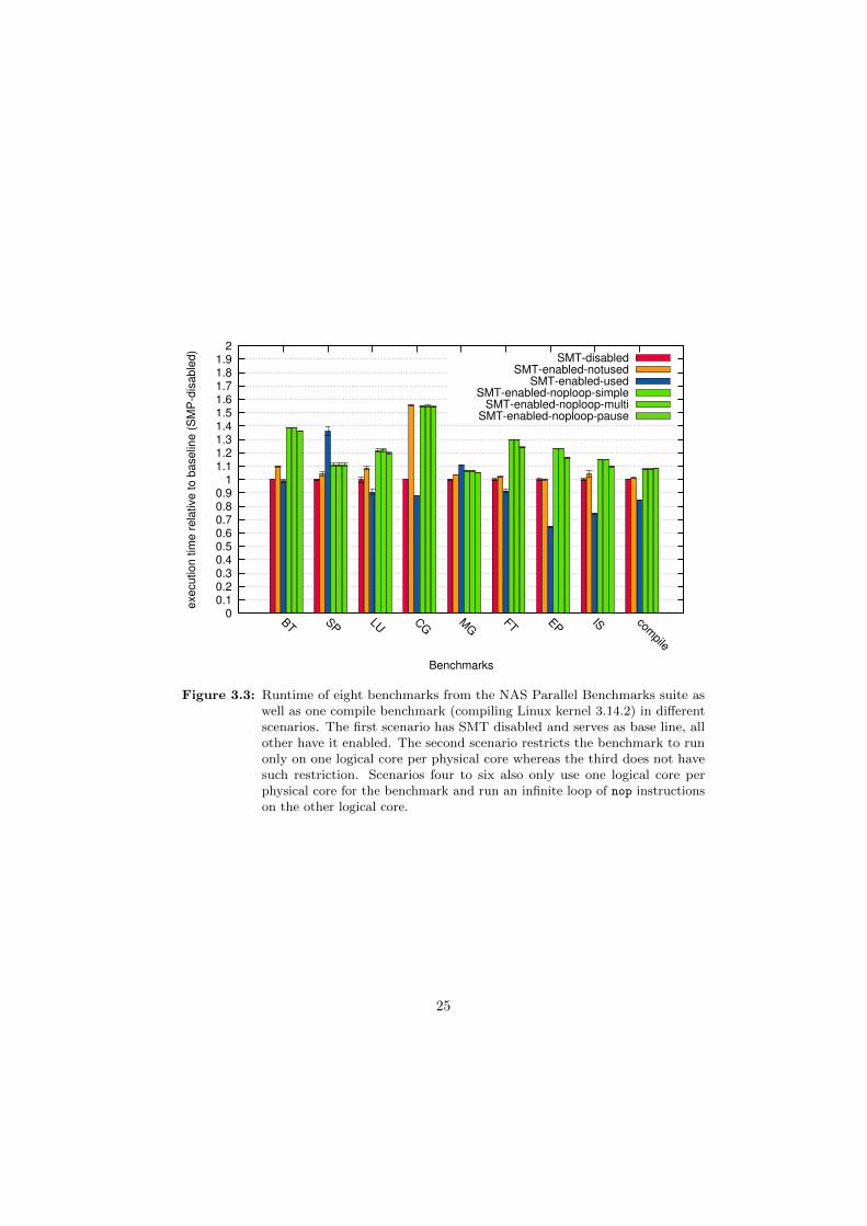
The measurements were performed on nine benchmarks in six different scenarios,Figure 3.3 shows the result. Eight of the nine benchmarks, namely block tri-diagonalsolver (BT), scalar penta-diagonal solver (SP), lower-upper gauss-seidel solver (LU),conjugate gradient (CG), multi-grid on a sequence of meshes (MG), discrete 3d fastfourier transformation (FT), embarrassingly parallel (EP) and integer sort (IS), arefrom the OpenMP reference implementation of the NAS Parallel Benchmarks [3]version 3.3.1 with class B problem size. The last benchmark (compile) measures thetime it takes to compile Linux kernel version 3.14.2 using eight threads (make -j8).
For the first scenario (SMT-disabled), Hyper-Threading was disabled in the BIOS.The benchmarks could make use of all four cores available on the i7-4770 with oneexecution context each. This scenario serves as the base line for comparison withother scenarios. All except the first scenario have Hyper-Threading enabled. In thesecond scenario (SMP-enabled-notused), the benchmarks were restricted to use onlyone execution context per core. Since nothing else was running on the test system,the second execution context of each core was running the Linux kernel idle loop.The third scenario allows benchmarks to use all execution contexts. The remainingthree scenarios are similar to the second in that the benchmarks are restricted touse only one execution context per core. In all three scenarios, four additionalthreads are spawned which are pinned to the execution contexts the benchmark is
24
0 0.1 0.2 0.3 0.4 0.5 0.6 0.7 0.8 0.9
1 1.1 1.2 1.3 1.4 1.5 1.6 1.7 1.8 1.9
2
BT SP LU CG
MG
FT EP IS compile
execution tim
e r
ela
tive to b
aselin
e (
SM
P-d
isable
d)
Benchmarks
SMT-disabledSMT-enabled-notused
SMT-enabled-usedSMT-enabled-noploop-simple
SMT-enabled-noploop-multiSMT-enabled-noploop-pause
Figure 3.3: Runtime of eight benchmarks from the NAS Parallel Benchmarks suite aswell as one compile benchmark (compiling Linux kernel 3.14.2) in differentscenarios. The first scenario has SMT disabled and serves as base line, allother have it enabled. The second scenario restricts the benchmark to runonly on one logical core per physical core whereas the third does not havesuch restriction. Scenarios four to six also only use one logical core perphysical core for the benchmark and run an infinite loop of nop instructionson the other logical core.
25
not using. Each of these threads executes an infinite loop of nop instructions. Thedifference between those scenarios is the kind of nop loop they are running. Scenariofour (SMT-enabled-noploop-simple) uses a one byte nop instruction encoded as0x90 whereas the fifth scenario (SMT-enabled-noploop-multi), uses the multi-bytenop instruction 0x0f 0x1f 0x00, which is one of the recommended multi-byte nop
sequences [29]. The sixth and last scenario (SMT-enabled-noploop-pause) uses thepause instruction. Each benchmark was ran ten times for each scenario.
Enabling SMT but not using it (SMT-enabled-notused) incurs a median slowdown of4.3% compared to the base line (SMT-disabled). We attribute this slowdown to thestatic partitioning of CPU resources when Hyper-Threading is enabled. Each of thetwo execution contexts per core gets half the resources of any statically partitionedresource like the number of entries in the reorder buffer (ROB) or the load and storebuffers [42]. Since only one execution context per core is used for the benchmark,there are less resources available when SMT is enabled but not used.
Enabling SMT and using it (SMT-enabled-used) is faster by 9.5% in the mediancase. This is to be expected as SMT generally improves performance by betterutilization of execution units.
Running a thread with an infinite nop loop using either the single byte (SMT-enabled-noploop-simple) or the multi-byte (SMT-enabled-noploop-multi) nop version hasidentical performance. Relative execution time ranges between a factor of 1.06and 1.55 with a median slowdown of 22%. The significant slowdown suggests thateven though the nop instruction does not alter the architectural state (except theinstruction pointer), it consumes execution resources. The x86 architecture thereforelacks a real nop instruction which does not consume execution resources.
Intel recommends to use the pause instruction in spin-wait loops [29]. It “will de-pipeline a thread’s execution, causing it to not contend for resources such as the tracecache until the pause has committed.” [42] However, using the pause instruction in aninfinite loop (SMT-enabled-noploop-pause) did not result in significant performanceimprovements compared to the other two versions of nop loops.
The results from Figure 3.3 invalidate our hypothesis that executing a nop loopon one hardware thread does not significantly slow down execution on the otherhardware thread. While the presented approach of using a helper thread or kernelto reduce polling time could be implemented with TSX, we do not expect that theslowdown incurred by executing a nop loop on the hyperthread can be compensatedby a reduced polling time and therefore did not further pursue this approach.
3.4 n : 1 communication channels
Yet another way to reduce polling time is to lower the number of communicationchannels. In Barrelfish, UMP channels are point-to-point channels between exactlytwo communication partners. Additionally, each channel internally consists of a
26

memory region for sending and receiving respectively. This has the benefit that nosynchronization is needed for the sender. On the downside, essential OS domainslike the monitor end up having to poll a large number of channels.
Using n : 1 channels with multiple senders and one receiver would drastically reducethe number of channels and therefore the time spent polling. For synchronizationbetween the senders TSX could be used. Depending on the implementation of themessaging channel, though, a single compare-and-swap would be all that is needed tosynchronize the senders. As mentioned in Section 3.1 Ritson and Barnes [38] foundthat using a single compare-and-swap instruction is faster that using a transaction.Therefore, CAS is a better fit as synchronization primitive for n : 1 communicationchannels.
3.5 Conclusion
In this chapter, we learned that the abort mechanism of TSX provides a low-overheadcontrol transfer. However, the current incarnation of TSX is not flexible enoughsuch that it can be repurposed and used for user-level notification. We explored twoalternative ways to accelerate message passing using TSX by reducing the pollingtime. The first approach relied on helper treading but did not yield the expectedperformance, while the second approach of using n : 1 channels can be better solvedby using compare-and-swap instructions instead of transactions.
We conclude that TSX, in its current form, cannot be used to accelerate messagepassing.
27

Chapter 4
Using Alert-on-Update toAccelerate Message Passing
In the last chapter we found that TSX cannot be used to accelerate message passing.In the first part of this chapter (Section 4.1) we will propose and describe a simpleISA extension alert-on-update (AOU) that allows a programmer to register an alerthandler which is invoked by hardware whenever any element in a set of memorylocations changes. Such a feature has been proposed before [40] but with a differentAPI and it has only been studied in the context of software transactional memory [39]whereas we use it for message passing.
The middle part of the chapter (Section 4.2) gives a high-level overview how the alert-on-update hardware feature can be used to accelerate user-level message passing byremoving the need for constant polling using Barrelfish’s user-level message passing(UMP) as a running example.
In the last part (Section 4.3), we describe how AOU fits into the larger messagepassing framework of the Barrelfish operating system. We present the API providedto the application programmer that allows to use alerts instead of polling for specificdomains and waitsets. Details as to how this API is implemented, will be given inthe next chapter. Barrelfish was chosen as the operating system to experiment withAOU because it already features a comprehensive message passing framework.
4.1 Alert-on-Update ISA Extension
This section presents the alert-on-update ISA extension. We decided to use ARMv7-A as the base ISA since it is a widely used instruction set, yet still much simplerthan x86. Also, CPU simulators as well as operating systems running on top of
28

the simulators were readily available to the author. While our discussion of AOUfocuses on ARMv7-A, most concepts are general enough such that they can beapplied to other ISAs as well.
The alert-on-update feature consists, at a high-level, of four new assembly instruc-tions, a set of memory locations that are monitored by hardware, an alert handlerthat is called by hardware whenever any of the monitored memory locations changes,and a memory buffer that is allocated by software and written to by hardware whenan alert is triggered.
4.1.1 Enabling and Disabling Alerts
The aou start instruction enables the receiving of alerts and takes two arguments.The first argument is the virtual address of the alert handler. When an alert happens,control is transferred to this address. The second argument is the virtual address ofa memory buffer. The programmer is responsible for allocating this buffer and itmust be at least 8 bytes in size.
The dual instruction aou end, which does not take any arguments, disables the useof alerts. No alerts are received after an aou end and before a subsequent aou
start. Moreover, the instruction clears the set of memory locations that weremonitored. After an aou end, the hardware no longer uses the memory bufferprovided as argument to the most recent aou start, and it can therefore be freed.
For each execution context provided by the CPU, alerts can be enabled and disabledseparately. The aou start and aou end instructions implicitly enable or disablealerts for the context they are executed in.
4.1.2 Modify Set of Monitored Memory Locations
The set of memory locations monitored can be modified by the aou monitor andaou release instructions. Both take as single argument the virtual address of thememory location to monitor or release respectively. The instruction aou monitor
adds a memory location to the initial empty set whereas aou release removes it.
Memory locations are handled at cache line size granularity. Any address thatcorresponds to a specific cache line can be used to add the corresponding cache lineto the set of monitored cache lines. Also, the argument provided to aou monitor
and aou release must not be aligned.
Each execution context has its own set of monitored cache lines and the aou monitor
and aou release instructions implicitly add or remove the cache line to the setbelonging to the context they are executed in. Note that these sets do not have tobe disjoint, a certain memory location can be monitored from multiple executioncontexts.
29

aou start <alert handler> <buffer address>aou monitor <address>aou release <address>aou end
Table 4.1: Alert-on-update ISA extension instructions.
Table 4.1 summarizes the four instructions that make up the alert-on-update ISAextension.
4.1.3 Alert
If any line from the set of monitored cache lines is modified by an execution contextother than the current one, an alert for the current context is triggered and thefollowing steps are performed in hardware. The current value of the r1 registeris written to the memory buffer at offset 0. Likewise, the current value of the pc
register is written to the buffer at offset 4. Next, the virtual address of the memorybuffer is stored in the r1 register and the address of the alert handler is storedin the pc register causing execution to continue at the alert handler. While analert is triggered, further alerts are disabled and the set of monitored cache lines iscleared as if an explicit aou end was called. Therefore, the alert handler must notbe reentrant.
old r1
old pc
r1 offset 0
offset 4
Figure 4.1: Alert handler register state: the r1 register points to the memory buffercontaining the old values of the r1 and pc registers.
Figure 4.1 depicts the state before the first instruction of the alert handler is executed.The r1 register points to the memory buffer containing the old values of the r1
and pc register from the time normal execution was interrupted by the alert. Allregisters except r1 and pc still contain the values from normal execution. It is atthe programmers discretion to save and restore the registers trashed by the alerthandler.
4.1.4 Implicit Disabling of Alerts
As mentioned before, alerts get implicitly disabled when an alert is triggered. Thereare, however, two other important cases that cause alerts to get disabled.
Firstly, alerts get implicitly disabled by any change in privilege level. For example,if the privilege level changes from PL0 (user mode) to PL1 (FIQ, IRQ, supervisor,
30

etc.), alerts get disabled. This entails that they get disabled when running in usermode and an interrupt happens or a supervisor call is made. If alerts were notimplicitly disabled by a change in privilege level, an alert handler that was setup inuser mode but triggered while at PL1 would have elevated access rights.
Secondly, alerts get disabled by any change in the TLB or cache configuration. Thisincludes all instructions that operate on co-processor 15.
An implicit disabling of alerts has the same effect as an explicit aou end, i.e. noalerts are received afterwards until the next aou start and the set of monitoredcache lines is cleared.
4.1.5 Spurious Alerts
In the usual case, an alert is triggered if alerts are enabled and a cache line getsmodified by a context other than the current one after it has been added to theset of monitored cache lines but before alerts were explicitly or implicitly disabled.However, for implementation dependent reasons, a spurious alert might happenanytime alerts are enabled. A spurious alert is any alert that is not triggered as theresult of a modification of a monitored cache line.
The semantic for when an alert is triggered is that whenever alerts are enabled,a modification of a monitored cache line always triggers an alert. However, theopposite is not true. An alert does not imply that a cache line was modified.
The hardware does not give any indication whether a particular alert was a spuriousalert or not. It is the responsibility of the programmer using application specificknowledge to check whether actually something changed.
4.2 Message Passing Without Polling
Now that we have an understanding of how the alert-on-update feature works, letus discuss how AOU can be employed to accelerate message passing. We will useBarrelfish’s UMP message passing as an example to guide the discussion.
The goal is to reduce the number of times polling is necessary and in many casesgetting rid of polling altogether by using alerts. This can be achieved in severaldifferent ways. The most straight-forward way, presented in Section 4.2.1, directlymonitors the cache line the next message will be received in. Alternatively, one canmake use of a dedicated memory region for notification (Section 4.2.2).
31

4.2.1 Monitor Message Channel
The setting we consider is that of a sending thread and a receiving thread runningon different cores in parallel, i.e. at the same time. The receiving thread wants toget notified when a message arrives without having to poll all the time.
To this end, the receiving thread enables alerts whenever it is scheduled using theaou start instruction. Moreover, it adds the memory location where the nextmessage will be received to the set of monitored memory locations using aou
monitor. Next, the receiving thread can continue its processing—it will get notifiedonce a message arrives.
The process of sending does not change at all. In fact, the sender does not even haveto know whether the receiver uses polling or relies on the alert-on-update feature.The sender simply writes the next message (cache line) to the message channel.This write will trigger an alert in the receiver, notifying it that a message arrivedand allowing it to act appropriately, for example, by handling the message rightaway or by unblocking a high-priority thread that will shortly handle the message.Afterwards, the receiving thread can continue at the point it was interrupted by thealert.
The receiver is not restricted to monitor a single channel. After it enabled alerts,it can monitor any number of channels. Moreover, channels that were torn downcan be removed and new channels that are established can dynamically be addedby using aou release and aou monitor respectively. Once an alert happens, thereceiver needs to check which of the monitored channel is ready as the hardwaredoes not give any indication which memory location caused the alert. Also, it couldhave been a spurious alert.
While polling is still necessary when an alert happens, frequent polling between thearrival of messages in order to provide low-latency message delivery is no longerneeded.
4.2.2 Dedicated Memory Region for Notifications
Instead of directly monitoring the cache line the next message will be received in,one can use a dedicated memory region shared between sender and receiver fornotifications. As we will see shortly, such a scheme can be used to further reducethe polling overhead by providing a hint which channels need to be polled once analert arrives.
In contrast to the approach presented in the last section, the process of sending doeschange. After the sender has written the next message to a certain communicationchannel, it writes a hint to the shared memory region that there is a pending messagefor the channel. There are many possibilities to encode such a hint but for thepurpose of the discussion let us assume that the shared memory region contains one
32
bit for each communication channel and the sender simply sets this bit to one toindicate a pending message for the channel. Alternatively, hints could be encodedusing Bloom filters [18].
The receiver does not monitor the cache line the next message will be received inbut instead monitors all the cache lines belonging to the dedicated memory region.Note that there is only one such memory region for all channels. Following an alert,the receiver only polls the channels for which the pending bit is set to one.
4.3 Barrelfish Application Programmer API
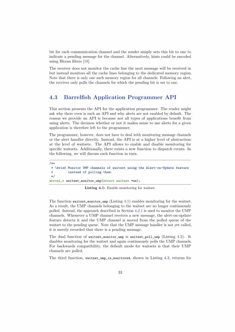
This section presents the API for the application programmer. The reader mightask why there even is such an API and why alerts are not enabled by default. Thereason we provide an API is because not all types of applications benefit fromusing alerts. The decision whether or not it makes sense to use alerts for a givenapplication is therefore left to the programmer.
The programmer, however, does not have to deal with monitoring message channelsor the alert handler directly. Instead, the API is at a higher level of abstraction:at the level of waitsets. The API allows to enable and disable monitoring forspecific waitsets. Additionally, there exists a new function to dispatch events. Inthe following, we will discuss each function in turn.
/**
* \brief Monitor UMP channels of waitset using the Alert-on-Update feature
* instead of polling them.
*/
errval_t waitset_monitor_ump(struct waitset *ws);
Listing 4.1: Enable monitoring for waitset.
The function waitset_monitor_ump (Listing 4.1) enables monitoring for the waitset.As a result, the UMP channels belonging to the waitset are no longer continuouslypolled. Instead, the approach described in Section 4.2.1 is used to monitor the UMPchannels. Whenever a UMP channel receives a new message, the alert-on-updatefeature detects it and the UMP channel is moved from the polled queue of thewaitset to the pending queue. Note that the UMP message handler is not yet called,it is merely recorded that there is a pending message.
The dual function of waitset_monitor_ump is waitset_poll_ump (Listing 4.2). Itdisables monitoring for the waitset and again continuously polls the UMP channels.For backwards compatibility, the default mode for waitsets is that their UMPchannels are polled.
The third function, waitset_ump_is_monitored, shown in Listing 4.3, returns for
33

/**
* \brief Poll UMP channels of waitset instead of monitoring them using the
* Alert-on-Update feature.
*/
errval_t waitset_poll_ump(struct waitset *ws);
Listing 4.2: Disable monitoring for waitset.
/**
* \brief Whether the UMP channels of the waitset are set to be monitored or
* polled.
*/
bool waitset_ump_is_monitored(struct waitset *ws);
Listing 4.3: Test whether waitset is monitored.
a given waitset whether their UMP channels are currently monitored using thealert-on-update feature or polled.
/**
* \brief Dispatch next event on given waitset or block waiting for it.
*
* Compared to event_dispatch() or event_dispatch_non_block() this function
* does NOT poll channels on the ’polled’ list and is intended to be used on
* a waitset where the UMP channels are monitored using the Alert-on-Update
* feature.
*/
errval_t event_dispatch_monitored(struct waitset *ws);
Listing 4.4: Event dispatch function for a monitored waitset.
As mentioned, for a monitored waitset the runtime automatically moves UMPchannels from the polled queue to the pending queue but the pending events on thechannels are not yet dispatched. To handle the events the application programmeris supposed to create a high-priority thread that calls event_dispatch_monitored
(Listing 4.4) in an endless loop. This function handles an event from a pendingchannel and blocks if no channels are ready. Compared to event_dispatch, it doesnot poll any UMP channels.
The high-priority thread ensures that whenever the domain is scheduled and thereare pending messages, these are handled first. Moreover, after an alert is receiveddue to a new UMP message, the alert handler unblocks the high-priority thread andenters the thread scheduler. This has the effect that the message is handled rightaway.
34

The presented programming model allows an application to perform lengthy compu-tations without having to sprinkle polls through the computation while still achievinglow latency message passing. The latter is achieved because the lengthy computationis interrupted by an alert and the message is handled before the computation isresumed.
35
Chapter 5
Implementation
This chapter describes how the APIs presented in the last section were implemented.The implementation of the alert-on-update ISA extension in the gem5 simulatorframework is described in Section 5.1. Section 5.2 gives implementation details onhow AOU is used inside Barrelfish’s message passing framework.
5.1 Alert-on-Update in Gem5
We implemented AOU in the gem5 [16] simulator framework. Gem5 was chosenbecause there was an existing port of Barrelfish for gem5 using the ARMv7-Aarchitecture [24] and because it provides flexibility to quickly model different typesof systems. For the purpose of our discussion, we assume the system consists of amulticore CPU with per-core L1 caches and one shared L2 cache.
The most natural way to add new instructions to the ARM instruction set is touse a specific co-processor and rely on the co-processor instructions mcr, mcrr,etc. For the AOU ISA extension we used co-processor number 3. Table 5.1 showshow the mnemonic instructions used so far (aou_start, aou_end, aou_monitor, andaou_release) map to the corresponding co-processor instructions.
Apart from four new instructions, the implementation of AOU uses two model-specific registers for each execution context of the CPU. The aou start instructionstores the address of the alert handler and the memory buffer address in those tworegisters. The buffer address must be aligned to four bytes, which makes the leasttwo significant bits available. The least significant bit is used as a flag to denotewhether alerts are enabled or disabled for the execution context. The aou start
instruction sets this bit whereas it is cleared by an aou end and by any of the eventsthat trigger an implicit disabling of alerts.
36

Mnemonic Name Actual Encoding
aou start mcrr p3, 0x0, <reg buffer>, <reg handler>, c0
aou end mcrr p3, 0x1, <reg any>, <reg any>, c0
aou monitor mcrr p3, 0x2, <reg addr>, <reg any>, c0
aou release mcrr p3, 0x3, <reg addr>, <reg any>, c0
Table 5.1: Encoding of AOU instructions using co-processor 3. The placeholder <reg
any> denotes that any of the registers can be used an that the actual value isignored.
The set of monitored cache lines is tracked in the L1 cache, which is local to eachcore. The state kept for each cache line is extended by an additional bit indicatingwhether the corresponding cache line is part of the set of tracked cache lines. Theaou monitor instruction sets the bit for the cache line corresponding to the providedmemory address whereas aou release clears it. An explicit aou end as well as anyevent that causes an implicit disabling of alerts clears all the bits.
An alert is triggered whenever a cache line that is marked as monitored is writtento by another execution context. The alert-on-update feature extends the cache-coherency protocol in order to detect such a change. Gem5 comes with two differentmemory systems. The classic memory system implements a snoop-based MOESIcache-coherency protocol that can be simulated rather fast. The Ruby memorysystem, on the other hand, is more flexible in the cache-coherency protocol andinterconnect used, and is typically used for research into cache-coherency proto-cols [17]. For our implementation, we used the classic memory system since it has amuch faster simulation speed and we did not require any of the additional flexibilityprovided by Ruby.
Figure 5.1 shows the extended MOESI cache–coherency protocol used. Circlesdenote the different states a cache line might be in whereas arrows denote local andremote events that cause a state transition. The left hand side of the figure (blackstates and arrows) shows the standard MOESI protocol with the terminology usedby AMD [5, Section 7.3]. They use the prefix “probe” to denote a remote event.
The extended MOESI protocol has four new states: AM, AO, AE and AS, whichwe will collectively refer to as alert states. They have the same meaning as theMOESI counterparts: M(odified), O(wned), E(xclusive) and S(hared), except thatadditionally the cache line is monitored. A monitor event brings a cache line fromone of the MOESI states to the corresponding alert state whereas a release brings itback. For example, a cache line residing in the M state transitions to the AM statein response to an aou monitor instruction on that cache line. In case a cache lineis monitored that was not yet present in the cache, i.e. the cache line was in theinvalid state, the cache line is loaded from lower level caches or main memory andput in the AS state.
The transitions between the AM, AO, AE and AS states are the same as the
37

M
O
E
S
I
Read M
iss
(share
d)
Pro
be W
rite H
it
Read HitProbe Read Hit
Read Hit
Read HitProbe Read Hit
Read HitWrite Hit
Read M
iss
(Exc
lusi
ve)
Wri
te M
iss
Wri
te H
it
Wri
te H
it
Wri
te H
it
Pro
be R
ead H
it
Pro
be W
rite H
it
Pro
be R
ead H
it
Pro
be W
rite H
itProb
e W
rite H
it
AM
AO
AE
AS
Pro
be R
ead H
it
Read HitProbe Read Hit
Read Hit
Read HitProbe Read Hit
Read HitWrite Hit
Pro
be R
ead H
it
Wri
te H
it
Wri
te H
it
Wri
te H
it
Monitor
Release
Monitor
Release
Monitor
Release
Monitor
Release
Monitor
Probe Write Hit + Alert
Figure 5.1: Extended MOESI cache-coherency protocol with four new alert states: AM,AO, AE, AS.
38

transitions between the M, O, E and S states except for the probe write hit event.In any of the alert states, such a remote write causes a transition to the invalidstate and triggers an alert.
To be more precise, the alert is not triggered right away, but it is recorded thatthere is a pending alert and it is triggered at the next possible moment. This isnecessary because otherwise the alert might be triggered at a point in time thatviolates atomicity. The strexd instruction, for example, guarantees that the 64 bitvalue is written atomically [11, Section A3.5.3]. If the alert were triggered rightaway and the first 32 bit write triggered an alert, atomicity would be violated.
Cache lines are only monitored in the L1 cache. A single bit is sufficient to indicatethat the cache line is part of the set of tracked cache lines. Which executioncontext the set is associated with is stored implicitly since the L1 cache belongs toa specific core and each core only has one execution context (ARM does not featureSimultaneous Multithreading). In order to support monitoring cache lines in theshared L2 cache as well, we would need to know which execution context the cacheline belongs to. While this information could be stored alongside each cache line inthe L2 cache it would use up scarce L2 space. Also, the space needed scales linearlywith the number of cores in the system. Therefore, do not track cache lines in theL2 cache.
As a result, a spurious alert is triggered whenever a monitored cache line is evictedfrom the L1 cache due to a capacity or conflict miss. To reduce the number ofspurious alerts, a victim cache [32] could be employed or the cache line replacementpolicy could be tweaked to favor cache lines that are monitored. We did not useany of these techniques because spurious alerts were not a problem in practice.
Since the changes to the CPU required for AOU are comparable to the changesrequired to support TSX, we are convinced that AOU is implementable in hardware.The set of monitored cache lines in AOU corresponds to the read-set in TSX. Bothare tracked in the L1 cache and a modification of any element of the set causes ahardware initiated control transfer to the alert handler or abort handler respectively.The difference is merely in the way new elements are added to this set. With TSX,all memory locations read within a transaction are implicitly added to the read-set,while with AOU, the cache lines can be explicitly added and removed by an assemblyinstruction. There are two other differences between TSX and AOU. Firstly, theyhandle interrupts and system calls differently. With TSX events like interrupts andsystem calls trigger an abort while with AOU they do not cause an alert but insteadwe simply stop monitoring. Secondly, TSX takes a snapshot of the register state atthe beginning of the transaction and restores this state for the abort handler. AOU,on the other hand, makes the register state from the time normal execution wasinterrupted available to the alert handler. Despite the mentioned differences, we areconvinced that AOU is implementable in hardware because the differences do notadd complexity but merely handle cases differently.
39

5.2 Barrelfish Implementation
This section details how the high-level API described in Section 4.3 is implemented.We start by describing how the UMP channels are monitored without creating arace condition (Section 5.2.1) and then walk through the steps that happen duringan alert (Section 5.2.2). Section 5.2.3 gives an overview of the TLA+ model—aformal model of the implementation—and describes the invariants we model checked.The last section, Section 5.2.4, elaborates why scheduler activations are essential forthe implementation and describes why using alerts in Linux is hard.
5.2.1 Monitoring UMP Channels
As presented in Section 4.3, the programmer uses the API call waitset_monitor_umpto enable monitoring the UMP channels belonging to the waitset instead of pollingthem. The dispatcher keeps a list of all the waitsets that are monitored. The APIcalls waitset_monitor_ump and waitset_poll_ump merely add or remove the waitsetto this list. Alerts are used if there is at least one waitset in the list.
All UMP channels belonging to a waitsets in the list are no longer continuously polledbut only at defined times. In particular, they are polled whenever the dispatcher isupcalled because a message could have arrived while the dispatcher was not running,and they are polled after an alert.
When the dispatcher is upcalled, not only are the UMP channels polled but they arealso monitored. The order in which these two operations are performed is important.If we were to poll the UMP channels first, there would exist a raise condition andif a message arrived between polling the channel and monitoring it, it would goundetected. To avoid this race condition, a UMP channel is first monitored andthen polled. If there is a pending message, the UMP channel is moved from thepolled to the pending queue of the waitset and the cache line that was monitored isreleased again.
5.2.2 Alert - Step-by-Step
To support alerts, a memory structure shown in Figure 5.2 is allocated when thedispatcher is created. It contains the memory region used by the alert-on-updatefeature, the address of the current dispatcher as well as the alert stack. Only thetwo words shown in red are written to by hardware, the rest is solely used by thesoftware alert handler. When alerts are enabled with aou_start, the address to themiddle of this structure, namely to the word labeled “offset 0”, is passed as thememory buffer argument. Later, when an alert is triggered, this address is stored inthe r1 register and we have the exact situation as shown in the figure.
40

r1 old r1 offset 0
old pc offset 4
offset 8dispatcher address
offset -4alert stack
used by AOU ISA extensionused by software
Figure 5.2: Layout of memory structure to support alerts. It contains the structure usedby the AOU feature as well as the alert stack.
Embedding the memory buffer used by the hardware in the structure used bysoftware gives the alert handler access to all state needed. It has access to the oldregister state (old r1 and pc register), has access to the current dispatcher and hasa stack to work with.
When an alert is triggered the software alert handler performs the following steps.First, it establishes a basic execution environment: setting up the stack and storingthe current value of a handful of registers such that they can be used as scratchregisters. Second, it is determined whether or not upcalls were effectively disabledat the time normal execution was interrupted by the alert. If they were, we merelyrecord that an alert happened but do not act immediately. Instead, the registerstate is restored and normal execution is resumed.
If upcalls were enabled, the register state at the time normal execution was inter-rupted is saved to the enabled save area of the dispatcher. Moreover, we disableupcalls and switch to the dispatcher stack where the second half of the alert handlerexecutes.
The second part of the alert handler enables alerts again and then polls the UMPchannels and monitors them with the scheme described in the last section. If any ofthe channels are ready and there is a thread blocked on the waitset, it gets unblocked.Subsequently, the thread scheduler is entered. In the intended programming model,there is a high-priority thread that handles the messages and the thread schedulerwill choose this one over the lower priority application thread, therefore handlingthe arriving message right away. Once all messages are handled, the high-prioritythreads blocks and the application thread is resumed again.
The alert handler is split in two because the first part of the alert handler is notreentrant. Therefore, it is unsafe to enable alerts while still executing on the alertstack. The second part of the alert handler actually is not reentrant either but itis never entered twice. If an alert happens while executing the second part of thealert handler, the first part restores the interrupted execution because upcalls aredisabled while the second part runs.
41

This is one example why it is essential for the first part of the alert handler torestore the interrupted execution instead of acting on the alert right away. Ingeneral, disabling upcalls is used in Barrelfish as a synchronization mechanism andimportant data structures like the dispatcher state or the thread control blocksmight not be in a consistent state while disabled. Therefore it would be unsafeto run the second part of the alert handler which enters the user-level scheduler.Instead of acting right away, the alert handler notes that an alert happened andrestores the interrupted execution. When we enable upcalls again, we check whetherthere was an alert while upcalls were disabled and handle it at that time.
So far, we only talked about the alert interrupting normal execution, all of whichhappens completely in user space. However, there is one more dimension to consider,namely the kernel interrupting user space. The kernel might interrupt user space atany time and it might happen that an alert interrupted normal execution and whilethe alert handler runs, the kernel interrupts user space.
Before we describe how such a scenario is handled let us quickly review how interruptsinteract with dispatchers in the absence of alerts. There are two cases to considerdepending on whether upcalls were enabled or disabled when the interrupt happened.If upcalls were enabled, the kernel saves the register state of the interrupted contextto the enable save area and once it finished processing the interrupt the dispatcheris upcalled. If upcalls were disabled, the register state is stored to the disabled savearea and the kernel resumes the dispatcher instead of upcalling it.
There is one more twist. Because of a race condition when the user level schedulerresumes a thread context, the kernel cannot just check the flag that indicates whetherupcalls are disabled or not. The race condition exists because upcalls are enabledbefore the full register state of the thread is restored, however, while the resumeoperation takes place, the dispatcher should still be considered disabled. Therefore,the kernel not only checks the flag that indicates whether upcalls are disabled or notbut also checks whether userland was resuming a thread when it was interrupted.The latter is done by checking whether the value of the pc register lies within theinterval of instruction addresses that correspond to the resume code. The kernelconsiders the dispatcher effectively disabled if the flag indicates that it is disabled orif the pc register lies in the resume range.
With alerts the interaction between kernel and dispatcher stays the same except forthe definition of effectively disabled. The kernel considers the dispatcher effectivelydisabled if the flag indicates that it is disabled or if the pc register lies in the resumerange or if the pc register lies in the alert handler range. The last check is necessarybecause we have a similar race condition in the alert handler that we have whenresuming a thread. As soon as the hardware triggers the alert, and while the alerthandler is running, upcalls should be disabled. However, we can only explicitlydisable upcalls after we have setup a basic execution environment. To account forthis discrepancy between the time the kernel should consider upcalls disabled andthe time the disabled flag is set, the kernel performs the additional check.
42

The check whether the dispatcher is effectively disabled happens at every interruptand on the fast path. Therefore, as an optimization, the code that resumes a threadand the alert handler are placed adjacently in the binary by putting them in adedicated section. As a result, we only have to check whether the pc register lieswithin this section.
5.2.3 TLA+ Model and Model Checking
The last section mentioned quite a few subtle implementation details one must getright and there are many more that we did not discuss. Part of the complexitystems from the fact that there are several different execution environments involvedeach with their associated stack and register state. First, there are user-level threadsthat store their register state in the thread control block if they are not running.However, if a user-level thread is preempted by the kernel, its state is temporarilystored in the enabled save area of the dispatcher. Then, there is the dispatcherwhose register state is created anew each time it is upcalled. If the dispatcher,running on its own stack, or a user-level thread with upcalls disabled is preempted,the register state is stored in the disabled save area. Finally, there is the alertcontext. If an alert is triggered, part of the state of the interrupted context is—outof necessity—temporarily stored on the alert stack and later moved to the enabledsave area.
To get high confidence that these different execution environments are always savedand resumed correctly, we wrote a formal model of the intended implementation usingthe TLA+ [34] specification language even before starting with the implementation.Furthermore, we used the TLC model checker [44] to assert that the register statefrom each execution environment is never overwritten or lost.
The full TLA+ specification can be found in Appendix B and the interested readeris encouraged to read it. While the specification might look daunting at first, it isextensively commented and most of the specification has a similar pattern. In thefollowing we give a brief overview of the specification.
Our specification models a single dispatcher and two user-level threads as well ashow they interact with interrupts and alerts. To keep the model to a reasonablesize, we only model the following variables: the flag indicating whether upcalls aredisabled or not, the enabled and disabled save area, the thread control blocks ofboth threads, the scheduler variable indicating which thread is currently running,whether or not alerts are enabled, the memory buffer used by the alert-on-updatefeature, and the program counter.
In TLA+, the execution of a system is described as a sequence of discrete steps. Eachstep leads from one state to a new one where a state is a particular mapping fromvariables to values. The specification determines the set of all allowed sequences. Itis formulated as an initial state and a set of next state actions.
43

The formula shown below is an example next state action. Note that in TLA+,unprimed variables refer to the current state while primed variables refer to thenext state.
ThreadYield∆= ∧ pc = “user”
∧ disabled ′ = TRUE
∧ ∨ pc′ = “disp save 1”
∨ pc′ = “disp switch 1”
∧ unchanged 〈enabled area, disabled area, thread1 tcb, thread2 tcb,
resume from, current , alerts enabled , alert buffer〉
The next state action is named ThreadYield and is one of several next state actions inour specification that model the steps occurring when a thread yields. In Barrelfish,the first operation that is performed when a thread yields is to disable upcalls andthe above formula models exactly that.
pc = userdisabled = FALSE
...
pc = disp_save_1disabled = TRUE
...
ThreadYield
current state next state
Figure 5.3: Example two states that relate by the ThreadYield action.
Intuitively, the action states that it is applicable whenever the program counter hasthe value “user” and that the next state has the same mapping from variables tovalues with two exceptions. First, the value of the variable disabled has the valueTRUE. Second, the value of the program counter is either “disp save 1” or “dispswitch 1”. Figure 5.3 shows one example where the ThreadYield action was used toget from the current to the next state.
Our specification has 22 next state actions which all follow a similar pattern asthe ThreadYield action. In each state the system is in, a subset of the next stateactions are applicable. In our case, there are usually three actions applicable. Oneof them describes the next action in program order, the other two correspond to aninterrupt and an alert respectively.
After we specified the system, we defined safety properties that should to hold inevery possible state. Subsequently, we used the TLC model checker to verify thatthese properties hold for every possible execution. Our initial design contained twodesign flaws which the model checker immediately identified. It also provided anexample trace where the problem occurred. This allowed us to quickly rectify thedesign.
44

Even though it was a considerable effort to write the formal specification, it hasproven worthwhile. The design flaws were subtle edge cases and they would havebeen nearly impossible to debug.
5.2.4 Scheduler Activations and Why Using Alerts in Linuxis Hard
Because a context switch implicitly disables alerts, they need to be enabled againeach time a dispatcher is scheduled. This can easily be done in Barrelfish becauseit supports scheduler activations [6]. A user-level thread that is preempted by thekernel is not directly resumed when the dispatcher is scheduled again, instead, thedispatcher is upcalled. This upcall makes the dispatcher aware of the fact that itwas interrupted by the kernel and allows it to reenable alerts.
Linux and UNIX-like systems do not support scheduler activations and processeshave no way to tell that they were interrupted. This makes it hard to use alertsefficiently. The only way how alerts can be used is by adapting the alert-on-updatehardware feature. In the following we discuss two different approaches how theAOU ISA extension can be changed to make it useful for a Unix-like system.
Kernel Restores Alerts for User Process
In the first approach, the kernel reenables alerts on behalf of the user programbefore the process is scheduled. To this end, the user process communicates to thekernel the address of the alert handler, the address of the memory buffer and allthe memory locations that should be monitored so that the kernel can setup alerts.
To make this work, the proposed AOU ISA extension must be slightly adapted.Remember that any change in privilege level implicitly disables alerts. If alertsare enabled in the kernel for userland, lowering the privilege level should no longerimplicitly disable alerts.
While such an approach works, it adds software overhead and hardware complexity.On the software side, the kernel must validate the information provided by the userprocess. On the hardware side, there are additional edge cases. For example, whathappens when a monitored cache line is modified after the kernel enabled alerts onbehalf on the user process but before it is scheduled? The alert cannot be triggeredright away as the alert handler would otherwise run with elevated access permissions.Thus, the hardware must remember that there was an alert for a particular userprocess and trigger it only after the process is scheduled.
45

Trigger Alert When Interrupted
In a second approach, the alert-on-update feature triggers a spurious alert whenan interrupt happens instead of implicitly disabling alerts. The way this works isthat whenever an interrupt happens while alerts are enabled, the interrupt remainspending and is handled after the alert is triggered but before the first instructionof the software alert handler executes. This is analogous to how TSX triggers aspurious abort when an interrupt occurs [28, Section 15.3.8.2].
With the change to the AOU feature described above, hardware triggers an alertwhenever a process is preempted and the software alert handler runs first thingwhen the process is scheduled again. This makes the process aware that it wasdescheduled and empowers it to reenable alerts.
This approach enables the efficient use of alerts on UNIX-like systems. It is, however,not without its downsides. On the one hand, it puts functionality in hardware thatcan easily be implemented in software. To elaborate on this, the changed hardwarebehavior emulates an upcall since the alert handler runs whenever the process isscheduled. Upcalls, however, can be easily implemented in software.
On the other hand, it increases the interrupt latency because processing the interruptis delayed until the alert is triggered. While this happens in TSX as well, transactionsare usually short lived, and as a result, the interrupt latency is only increased inthe unlikely case that it occurs while a transaction is active. Alerts, on the otherhand, are enabled most of the time.
Other Approaches
Other approaches are possible including ones where the hardware saves and restoresall alert state for a process. Such approaches, however, require extensive hardwaresupport and we did not consider them further because there were no compellingadvantages over the two approaches presented above.
46

Chapter 6
Evaluation
This chapter evaluates the performance of Barrelfish’s user-level message passing(UMP) when alerts are used to notify the receiver and compares it to the standardmeans for the receiver to detect a new message: polling. If not stated otherwise,gem5 was configured to emulate a machine with the parameters shown in Table 6.1.
CPU Atomic Simple, ARMv7-A, 2 cores, 1GHzL1 dcache 64KB per-core, 2-way associative, 2 cycles hit latencyL1 icache 32KB per-core, 2-way associative, 2 cycles hit latencyL2 cache 2MB shared, 8-way associative, 20 cycles hit latencyDRAM 256MB, 30 cycles access latency
Table 6.1: Gem5 simulation parameters.
6.1 Alerts versus Tight Polling
The first microbenchmark compares a receiver that uses alerts to one that uses atight polling loop to detect the arrival of a new message. The experiment setupconsists of a sender running on one core and a receiver running on another. Tocommunicate, a single UMP channel is used.
In case the sender uses alerts, we make use of the intended programming modeldescribed in Section 4.3 of creating an additional thread that is usually blockedbut gets unblocked and scheduled when a message arrives. For the purpose of thebenchmark, the main thread performs a dummy computation: summing up numbers.In case the sender uses polling, there is only one thread which continuously pollsthe UMP channels.
47

Because of the overhead associated with an alert—setup and teardown of the alertstack, entering the user-level scheduler and switching to the thread that handles themessage—we expect that using polling is faster compared to alerts. Keep in mindthough, that with polling we waste our cycles checking the arrival of a new messagewhile with alerts the main thread can perform useful work.
For the experiment, a total of 1000 messages are sent from sender to receiver, eachcarrying two 32 bit words as payload. For sending and receiving, the high-levelFlounder message passing framework is used. The latency for each message is timedindividually. We start measuring right before the transmit function is called andstop once the receive callback is invoked.
Using a tight polling loop resulted in a median message latency of 1137 cycles, and alatency of 1611 cycles when alerts are used. As expected using polling is faster thanusing alerts, but it is noteworthy that alerts only add 500 cycles overhead comparedto polling.
high-levelsend
low-levelUMP send
20%
alert-handlercalled
UMP channelspolled
low-levelUMP receive
high-levelreceive
13% 22% 33% 11%
messagemarshalling
detect sending,trigger alert,
setup alert stack
switch to dispatcher stack,poll all UMP channels,
move ready channels topending queue
unblock thread,run user-level scheduler,
switch threads
demarshalling
events receiver
events sender
Figure 6.1: Message latency breakdown.
Figure 6.1 shows a timeline of the different activities that happen between the sendand receive and breaks down the time spent in each as a percentage of the totalmessage latency. Events depicted in green occurred at the sender while blue eventshappened at the receiver.
To marshall the message and get from the high-level send function to the low-levelUMP send accounts for 20% of the total message latency. After the message wassent, it takes approximately 210 cycles (13%) to detect that there was a message,trigger an alert and for the receiver to setup the execution environment for the alerthandler. Subsequently, the receiver switches to the dispatcher stack, polls all UMPchannels to check which one is ready, and moves the ready channels to the pendingqueue of the corresponding waitset; all of which uses up 22% of the total messagelatency. One third of the time is the spent unblocking the high-priority thread thatwill handle the message, running the user-level scheduler and dispatching that verythread. Finally, it takes another 11 percentage points to demarshall the low-levelUMP message and invoke the registered message handler.
48

6.2 Alerts versus Polling at Different Polling Fre-quencies
The second benchmark models an application that performs a compute-intensivetask but every so often receives a UMP messages which should be handled in atimely manner. The task consists of summing up all the numbers between 0 and107 − 1 using 64 bit additions.
We provide two different implementations of the benchmark. The first uses alertsto detect new messages and consists of two threads. One thread performs thesummation task while the other is responsible for handling incoming messages andis blocked if there are none. The second implementation uses polling to check fornew messages and only employs one thread. This thread interleaves summing upthe numbers with polling. After a configurable number of summation operations,the thread polls the UMP channels. This implementation has a tradeoff betweenthe polling frequency and the overhead due to polling. Choosing a higher pollingfrequency results in a lower message latency but, on the downside, increases thetotal runtime.
We compare the implementation using alerts with the polling implementation atdifferent polling frequencies. The UMP messages sent to the application originatefrom a load generator running on a different core. A single UMP channel is used forsending the messages from the load generator to the application. The load generatoris configured to send a message carrying a two word payload every 1 to 50 ms. Theexact time when the next message is sent is chosen uniformly at random from thisinterval.
total time [s] total timeslowdown
median mes-sage latency[cycles]
median mes-sage latencyslowdown
polling never 3.661 - ∞ -polling 106 3.675 0.38% 180’910’028 15’911’072%polling 105 3.682 0.60% 20’673’991 1’818’193%polling 104 3.690 0.80% 1’890’584 166’178%polling 103 3.701 1.11% 191’297 16’725%polling 102 3.727 1.82% 21’094 1’755%polling 50 3.752 2.49% 11’605 921%polling 25 3.794 3.64% 6’637 484%
alerts 3.700 1.06% 1’611 42%
Table 6.2: Benchmark results from compute-intensive task that also receives UMP mes-sages using 1 channel.
Table 6.2 shows the result of the benchmark. It lists the total time it took tocomplete the summation task and the median message latency from the time the
49

load generator sent the message until the application handled it. Additionally, itshows the slowdown of the total time and the slowdown of the median messagelatencies compared to the respective baseline. As baseline for the total time serves arun of the benchmark that uses the polling implementation but the polling frequencywas set so low that the channels were never polled and therefore no messages werehandled. This run is labeled “polling never” in the table. The baseline for themedian message latency is the result obtained in the last section, where we usedtight polling. This slowdown represents how much slower it is to use alerts or pollingat a fixed frequency compared to the fastest way to detect a new message: tightpolling.
We performed seven benchmark runs with different polling intervals. For each pollinginterval, the benchmark was run only once. However, since gem5 has deterministricsimulation, there is no point in repeating a benchmark run with the same parametersas it results in exactly the same outcome.
Polling every 25 addition operation resulted in a low message latency of 6’637 cyclesbut the total runtime of the application increased by 3.64%. At the other end ofthe spectrum, if we poll every one million iteration, the application runtime is notsignificantly affected but the message latency increases to 181 · 106 cycles whichequals 181 ms. Using alerts resulted in the lowest latency of 1’611 cycles and anoverhead of 1.06%.
Using the detailed statistics provided by the gem5 simulator allowed us to analyzewhere the application overhead stems from. Comparing alerts to polling every 25iterations shows that with polling there are 5.0% more memory references (loadsand stores) whereas with alerts there are 4.1% more instruction cache misses. Thereare more memory references with polling because the UMP channels are checkedmore frequently, resulting in more read operations. With alerts there are moreinstruction cache misses because more distinct code is executed.
These results attest that there are several tradeoffs to consider when decidingwhether or not to use alerts. If low-latency messaging is of utmost importance or ifthe application has nothing else to do, it is best to use a tight polling loop. This givesthe lowest message latency. In case the application is not just waiting for the nextmessage to arrive but has other useful work to perform, alerts are a good fit. Whilethe message latency increases, it is still much lower compared to regularly checkingfor new messages. Also, the application overhead of using alerts is low. Polling atregular intervals only makes sense if low latency message passing is not requiredand a message latency in the order of magnitude of milliseconds is acceptable. Insuch a case, polling provides a small performance advantage. However, since theperformance gain is low—less than 1%—and polling at regular intervals entailssprinkle code that checks the message channels all over the application, we wouldargue that alerts are better suited. They provide a cleaner programming constructsince the application task and the polling are not intertwined.
50

6.3 Alerts versus Polling with Multiple UMP Chan-nels
In the benchmark from the last section all the messages arrived on a single UMPchannel and therefore only one channel had to be polled. However, it is commonfor Barrelfish applications to make use of multiple UMP channels, and essentialsystem services like the monitor or the memory server easily end up having to polldozens of channels. In this section, we repeat the experiment from the last sectionbut increase the number of UMP channels used. The messages might now arrive onany of them and the application has to poll them all.
0
5
10
15
20
25
30
35
40
45
50
55
25 50 100 1000 10000 100000 1000000
Overh
ead [%
]
Polling interval
Application overhead for 1, 10 and 100 UMP channels
1 UMP channel10 UMP channels
100 UMP channels
Figure 6.2: Application overhead when polling at different intervals and for an increasingnumber of UMP channels.
Figure 6.2 shows the application slowdown due to regularly polling 1, 10 and 100UMP channels. The results for 1 UMP channel are from the experiment in thelast section and are shown for comparison. When multiple channels are polled, theoverhead quickly increases, especially for high polling frequencies. For example ata polling interval of 25, the overhead is 3.64% for one UMP channel, 7.89% for 10and 50.34% for 100 UMP channels.
In contrast, the application slowdown when using alerts is not significantly affected
51

by the number of UMP channels. With one UMP channel the overhead is 1.06%,with 10 1.09% and with 100 UMP channels 1.15%. This favorable scaling makesusing alerts preferable over regular polling in case there are many UMP channels tocheck.
52
Chapter 7
Related Work
Ritson and Barnes [38] perform a similar performance study of TSX as we did inChapter 3 and then go on to list possible use cases outside of transactional memory.They identify that TSX can be used by a user application to detect context switchesas well as for user-level exception handling because, for example, a null pointerdereference causes the transaction to abort but the operating system will not beinvoked. Also, TSX can be used to implement choice over events analogous to whatwe use to detect an incoming message with multiple UMP channels.
Alert-on-update has been proposed before [40] [39]. Spear et al. use the alert-on-update feature as a simple hardware-assist to accelerate a software transactionalmemory system. While our feature resembles theirs, it differs in various aspects.Apart from a different API, their solution has two different mechanisms to deliveran alert depending on whether it happens while executing in user or kernel mode.An alert happening in user mode causes a simple control transfer while one occuringin kernel mode takes the form of an interrupt. Also, our implementation extendsthe MOESI cache-coherency protocol while theirs uses MESI.
Diestelhorst et al. [21] propose a small modification to AMD’s Advanced Synchro-nization Facility (ASF) that makes the full register state available to the aborthandler, therefore enabling the transaction to resume. For example, it would bepossible to resume the transaction after an interrupt or system call. With themodification, ASF could also be used for alert-on-update.
Isaacs [31] proposes an alternative notification scheme for Barrelfish’s user-levelmessage passing that relies on kernel support and uses inter-processor interrupts.Since it is rather heavy-weight compared to the size of the message, it is not meantto be used on every message. Rather, the programmer can decide to expedite certainlatency-sensitive messages. Our approach is more light-weight since it neitherinvolves the kernel nor inter-processor interrupts, but, on the downside, only worksif sender and receiver are currently running.
53
Chapter 8
Conclusion and Future Work
We have studied point-to-point message passing between two threads running inparallel on two cores which are part of the same cache-coherency domain. Afteranalizing the performance characteristics of Intel TSX, we found that while thebasic mechanism of monitoring multiple cache lines and triggering a control transferwould be useful for message notification in the above described scenario, the APIexposed by TSX is not flexible enough.
Thus, we presented a hardware mechanism called alert-on-update that carries overthe basic mechanism from TSX but can be used outside of transactional memory.We used AOU in the context of Barrelfish’s user-level message passing to notify thereceiver of a new message and integrated the use of alerts into the larger messagepassing framework of Barrelfish. To get high confidence that our implementation iscorrect, we wrote a formel specification in TLA+ and model checked it.
Measuring the effectiveness of message passing with notifications, we found thatit is most useful if low-latency message delivery with latencies below the schedul-ing quantum are required. It provides comparable, though unsurprisingly higher,message latencies compared to tight polling with the advantage that no cycles arewasted on polling and can instead be used for application processing. Comparingthe use of alerts to polling at regular intervals revealed that alerts provide lowerlatencies and a cleaner programming construct.
8.1 Directions for Future Work
8.1.1 Alert-on-Update and Fast Mutexes
We have studied using alert-on-update for message passing and others have appliedit to software transactional memory. AOU has other applications like fast mutexes
54

that are worth investigating.
Consider, for example, a high-priority thread T1 running on core 0 that is blockedbecause it tried to acquire a mutex which is currently held by another thread T2
running on core 1. Because T1 is blocked, core 0 runs a lower-priority thread T3.Once T2 releases the mutex, we would like to schedule the high-priority thread T1
as fast as possible. This can be achieved either by involving the kernel and using aninter-processor interrupt, or by using alerts.
The scenario has many similarities to message notification: in both cases there is anevent on one core that needs to be delived to another. In the same way that usingalerts is the better choice for message notification, we believe that it will be for fastmutexes.
8.1.2 Alert-on-Update and Hardware Transactional MemoryCo-design
As discussed in detail in Section 5.1, alert-on-update and hardware transactionalmemory (HTM) like Intel’s TSX share many similarities. At the heart of bothsolutions lies cache-line tracking and a hardware initiated control transfer. It wouldbe worthwhile exploring whether a common hardware feature could be used for bothalerts and hardware transactional memory, and the implications such an approachwould have.
55

Appendix A
Changes to the BarrelfishOperating System
The ARMv7 port of Barrelfish for the gem5 simulator was not used much since itsinitial implementation in 2012 [24]. Over time, many bugs made their way into thecode. As part of this thesis, countless bugs were fixed. In the following, we describetwo of the more involved bugs.
A.1 Timers and Timer Interrupts
The VExpress EMM platform that our configuration script of gem5 simulatesfeatures two SP804 [7] double timer modules as well as Cortex A9 core privatetimers [8, Section 4.2]. Before our bugfix, one SP804 module was used as the timerinterrupt for all cores and the interrupt was configured in N-N mode [10, Section1.4.3] at the Generic Interrupt Controller (GIC). In this mode, each core receivesand must acknowledge the interrupt independently.
The implementation had two problems. On the one hand, the calculations of thecounter value assumed the timer was running at the 1GHz system clock while inreality is was running at the 1MHz peripheral clock. As a result, the timer interruptwas only triggered once every 5 seconds instead of every 5 milliseconds. On theother hand, the GIC implementation in gem5 does not support interrupts in N-Nmode and resorted to 1-N mode sending the interrupt only to core 0.
One way to fix the issue would have been to use both timers of each of the twoSP804 modules we have on the VExpress EMM platform, one for each of the fourcores we support. We chose an alternative way of using the core private timers ofthe Cortex A9. This makes the code simpler since we do not need to assign timers
56

to cores, is how we do it on the PandaBoard and is less platform-specific.
During bootup, each core configures its private timer to interrupt every timeslice.Since this timer is private to the core, the interrupt is also only delivered to thatcore.
A.2 ARM ABI
The second problem arose because we link together object files compiled for differentABIs. Barrelfish applications are compiled for the ARM Architecture ProcedureCall Standard (AAPCS) [9] with two exceptions. First, the r9 register is reserved tocontain the address of the current dispatcher at all times1. Second, the r10 registeralways points to the global offset table2.
However, Barrelfish applications are also linked against libgcc that comes withthe compiler and which uses the unmodified ARM Architecture Procedure CallStandard. The libgcc library provides a low-level runtime and the compiler isfree to insert calls to the library at anytime. It is used for example for integerdivision or floating-point arithmetic on machines that do not support such operationsnatively [2].
Linking together code compiled for different ABIs is generally discouraged. If it isdone nevertheless, great care must be taken. The specific problem we encounteredwas the following. The application was performing a division and since the hardwaredid not provide a native instruction for it, a soft implementation from libgcc wasused. The division function adhering to the AAPCS ABI stored the callee-save r9and r10 register on the stack at the beginning of the function but freely used themafterwards. During the division function an alert was triggered and control wastransferred to the alert handler. The alert handler code, however, was compiledfor the modified AAPCS ABI and assumed that the r9 and r10 register containedthe address of the current dispatcher and the address of the global offset tablerespectively. This did not hold anymore and the alert handler was unable to accessany global variable or call any Barrelfish library function that referenced the currentdispatcher. Being unable to do either, the alert handler could not perform anyuseful work.
One way to fix the issue would have been to compile libgcc with the same modifiedABI as Barrelfish applications are. However, the Barrelfish team decided on anotheroccasion that they rather make the operating system work with a blessed compiler3
than to start modifying both or require to build the compiler with different flags forthat matter.
1 GCC flag -ffixed-r92 GCC flags -msingle-pic-base and -mpic register=r103 At the time of writing the blessed compiler is MentorGraphics Sourcery CodeBench Lite Edition
Version 2012.03.
57

So we set out to make Barrelfish work if linked against libgcc compiled for theunmodified AAPCS ABI. In a first step, we changed the ABI used by Barrelfish suchthat the r10 register is no longer dedicated to hold the address of the global offsettable. This change makes the r10 register available as a general purpose registerand brings the ABI closer to the AAPCS.
Even though the address of the global offset table is no longer available in a dedicatedregister, our applications are still position independent executables. If a globalvariable is accessed, the address of the global offset table is found using pc-relativeaddressing. While this increases the overhead of accessing global variables, we areconvinced that overall application performance does not get worse since the compilernow has one more register available for code generation.
Changing the ABI and making r10 a general purpose register enabled the alerthandler to correctly access global variables. If a global variable is referenced inthe alert handler, it no longer assumes any particular value of the r10 registerbut instead computes the address using the current program counter. They onlyremaining difference between the Barrelfish and libgcc ABI is the use of the r9register.
Unfortunately, it is much harder to remove this ABI difference. For an applicationthat only runs on one core, the dispatcher address could be stored in a globalvariable instead of keeping it in the r9 register. An application that spans multiplecores has one dispatcher per core, the global variable therefore would have to pointto different dispatchers depending on which core the global variable is dereferencedon. While this could be implemented using a different page table structure for eachcore and map the page containing the global variable to a different physical frameon each core, it adds complexity and duplicates state—at least the first level pagetable cannot be shared.
For these reasons, we decided not to opt for removing the ABI difference but todeal with the fact that our Barrelfish ABI assumes the r9 register always containsthe dispatcher address while the libgcc ABI freely uses it. Care must be takenwhenever a new context is established, i.e. when the kernel upcalls the dispatcher,when a new domain or thread is created, and when the alert handler sets up thecontext for itself to run. In all these cases the r9 register must be explicitly set topoint to the current dispatcher.
In case of the alert handler this is handled as follows. When the alert stack isallocated, the dispatcher address is stored at offset 8 (see Figure 5.2 on page 41).The alert handler then bootstraps itself by loading this address into the r9 registerbefore calling any Barrelfish functions and saves the value the r9 register had before,so that the interrupted context can be properly restored.
58

Appendix B
TLA+ Specification
module aou
The TLA+ specification at hand models the interactions between dispatchers, user-level threads,interrupts and alerts in the Barrelfish operating system. It is used together with the TLC modelchecker to verify that the execution state of threads and dispatchers is retained even if normalexecution flow is interrupted by user-level alerts and interrupts.
The specification models a single dispatcher with two user-level threads all running on a singlecore. A thread can yield at any time resulting in a thread switch or a sys yield of the dispatcher.In the latter case, the dispatcher is upcalled at the run entry point once the kernel schedulerdecides to run the dispatcher again. Following a run upcall, the dispatcher either resumes thethread that ran before or schedules another one. While executing in user-mode an asynchronousinterrupt may happen at any time. Depending on whether upcalls were enabled or disabled atthe time the interrupt happened, the kernel will either upcall the dispatcher or resume it. Lastly,user-level alerts may happen asynchronously anytime they are enabled. Following a notification,the user-level thread scheduler is entered and potentially a new thread is scheduled.
In TLA+, the execution of a system is described as a sequence of discrete steps. Each step leadsfrom one state to a new one where a state is a particular mapping from variables to values. Thespecification determines the set of all allowed sequences. It consists of the initial state Init andall allowed next state actions Next . The specification consists of the following variables. TheTypeInvariant located near the end of this specification list all the possible values the variablesmay attain.
59

disabled Boolean flag that is part of the dispatcher state and indicates whether upcalls areexplicitly disabled or not. In the following if we refer to a disabled dispatcher we mean thatupcalls are disabled.
enabled area One of the two save areas used by the kernel to store user-space state in case aninterrupt happens. The enabled area is used if the dispatcher was enabled and thereforestores the state of the user-level thread that was running when the interrupt happened.
disabled area The other save area used by the kernel. It stores the state of the dispatcher if itwas interrupted while being disabled.
thread1 tcb Thread control block for thread 1 containing the thread state if another thread iscurrently active.
thread2 tcb Thread control block for thread 2 containing the thread state if another thread iscurrently active.
resume from Either the enabled area or the TCB are used to resume a thread. This variableindicates which area is used to resume the thread and corresponds to the argument of thedisp resume function in lib/barrelfish/arch/<arch>/dispatch.c.
current Variable which is part of the dispatcher state and indicates whether ”thread1” or ”thread2”is currently active.
alerts enabled Boolean flag indicating whether alerts are enabled or not. This flag is part of thehardware state.
alert buffer Buffer allocated by software but written by hardware when an alert happens. In ourmodel it contains only the value of the program counter at which the normal control flowwas interrupted by the notification handler.
pc The program counter assumes string values and is used to model program order.
Four of the above variables, namely enabled area, disabled area, thread1 tcb and thread2 tcb,store the register state. While the real system contains some dozens registers, we model only tworegisters named r1 and r2. This makes the model much simpler and readable while still beingable to distinguish, for example while storing the full register state to the save area, between aninterrupt that happened before, in between or after registers r1 and r2 were stored to the save area.
Instead of storing the actual value of a register to the save area, we store the number of store andload operations performed. Each store increases the value by one whereas each load decreases itby one. If our specification is correct, only values 0 or 1 should ever appear. A value of 2, forexample, would be an error because there were two store operations without a load operation inbetween. Intuitively, this means that the state stored the first time is never read but overwrittenby the second store. The TypeInvariant states that only values 0 and 1 are correct and the modelchecker verifies that the invariant actually holds for the specified system.
Apart from the fact that the state is retained at all times, many more properties are checked.Section ‘safety properties’ at the end of this specification list the properties in details.
Since in Barrelfish all kernel operations are done with interrupts disabled, they are modeled as asingle atomic step (atomic in the sense that no other action is allowed to come in between) withonly the changes that are visible once we’re back to user space.
At a high-level alerts fit into the existing Barrelfish system as follows:• they are enabled in the ‘run’ upcall• they are disabled explicitly before we enter disabled mode• they are disabled implicitly by an interrupt (because we traverse the user-kernel boundary)• after the alert handler, we enter the thread-scheduler
60

The system model at hand uses several simplifications compared to the real system to keep themodel simple and to a reasonable length. The most important of those are:
• pagefaults and traps are not modeled• there are two static threads, creating and destroying threads is not possible• threads don’t block• system calls are not yet modeled• we don’t check any liveness properties like []<> pc = "user" yet.
extends Naturals
variables disabled , disabled area, enabled area, thread1 tcb, thread2 tcb,
resume from, current , alerts enabled , alert buffer , pc
vars∆= 〈disabled , disabled area, enabled area, thread1 tcb, thread2 tcb,
resume from, current , alerts enabled , alert buffer ,
pc〉
***************************** Utility functions ****************************
Given a program counter ’p’, indicates whether or not we are currently resuming a user-level
thread.
inside resume range(p)∆= p ∈ {“resume 1”, “resume 2”, “resume 3”}
Given a program counter ’p’, indicates whether or not we are currently inside the critical section.The critical section spans all code where the disabled flag is set to false but the dispatcher stillshould be considered disabled. This includes two cases. First, during resume, the disabled flag isset to false and then all the registers of a thread are restored and execution of the thread continues.Second, while in the notification handler we always should be considered disabled even before thedisabled flag is explicitly set to false.
inside cs(p)∆= inside resume range(p) ∨ p ∈ {“ahandler 1”, “ahandler 2”,
“ahandler 3”, “ahandler 4”,
“ahandler 5”}
Given a program counter ’p’, indicates whether or not we are effectively disabled. Effectivelydisabled means that either the disabled flag is explicitly set or the program counter is within thecritical section.
effectively disabled(p)∆= disabled ∨ inside cs(p)
Save specified register to save area.
As mentioned above, saving a register to the save area increments the corresponding counter by
one. For example: SaveRegisterTo([r1 7→ 0, r2 7→ 0], “r1”) = [r1 7→ 1, r2 7→ 0]
61

The implementation relies on the fact that records are functions in TLA+.
SaveRegisterTo(area, register)∆= area ′ = [area except
! [register ] = area[register ] + 1]
Load specified register from save area. Dual function to ’SaveRegisterTo’.
LoadRegisterFrom(area, register)∆= area ′ = [area except
! [register ] =
area[register ]− 1]
******************************** Initial state *****************************
The initial state is an enabled dispatcher with thread 1 running. All of the save areas are invalidexcept for the thread control block of thread 2 which contains its state. Notifications are enabledbut the notification buffer does not yet contain valid data. Moreover, the program counter is setto “user” indicating that we are currently executing user code, i .e. the actual user application.
The initial state is somewhat arbitrary and one could just as well start off at another state.
Init∆= ∧ disabled = false
∧ enabled area = [r1 7→ 0, r2 7→ 0]
∧ disabled area = [r1 7→ 0, r2 7→ 0]
∧ thread1 tcb = [r1 7→ 0, r2 7→ 0]
∧ thread2 tcb = [r1 7→ 1, r2 7→ 1]
∧ resume from = “invalid”
∧ current = “thread1”
∧ alerts enabled = true
∧ alert buffer = [pc 7→ “invalid”]
∧ pc = “user”
**************************** Next step actions *****************************
Yielding a thread is an action that is explicitly invoked by the currently running thread. It involvesdisabling upcalls followed by a decision of the user-level scheduler to run another thread or to yieldthe dispatcher. Our specification does not include the variables that decide which action occurs.Therefore, we simply specify that both actions are allowed behavior.
Code location:
thread yield in lib/barrelfish/threads.c
ThreadYield∆= ∧ pc = “user”
62

∧ disabled ′ = true
∧ ∨ pc′ = “disp save 1”
∨ pc′ = “disp switch 1”
∧ unchanged 〈enabled area, disabled area,
thread1 tcb, thread2 tcb, resume from,
current , alerts enabled ,
alert buffer〉
Switching from one thread to the other involves the following steps: Determine the next thread torun. Since we only have two threads in our model, we always run the other thread. (DispSwitch 1)Save the state of the thread that was running before to the thread control block. (DispSwitch 2
and DispSwitch 3).
Code locations:thread yield in lib/barrelfish/threads.c
disp switch in lib/barrelfish/arch/<arch>/dispatch.c
DispSwitch 1∆= ∧ pc = “disp switch 1”
∧ if current = “thread1”
then ∧ current ′ = “thread2”
∧ resume from ′ = “thread2”
else ∧ current ′ = “thread1”
∧ resume from ′ = “thread1”
∧ pc′ = “disp switch 2”
∧ unchanged 〈disabled , enabled area, disabled area,
thread1 tcb, thread2 tcb, alerts enabled ,
alert buffer〉
DispSwitch 2∆= ∧ pc = “disp switch 2”
∧ if current = “thread1”
then ∧ SaveRegisterTo(thread2 tcb, “r1”)
∧ unchanged 〈thread1 tcb〉
else ∧ SaveRegisterTo(thread1 tcb, “r1”)
∧ unchanged 〈thread2 tcb〉
∧ pc′ = “disp switch 3”
63
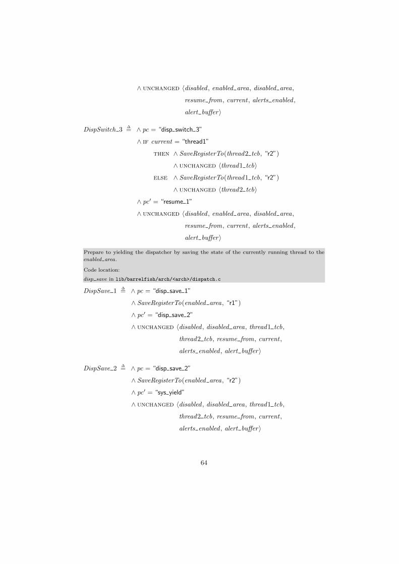
∧ unchanged 〈disabled , enabled area, disabled area,
resume from, current , alerts enabled ,
alert buffer〉
DispSwitch 3∆= ∧ pc = “disp switch 3”
∧ if current = “thread1”
then ∧ SaveRegisterTo(thread2 tcb, “r2”)
∧ unchanged 〈thread1 tcb〉
else ∧ SaveRegisterTo(thread1 tcb, “r2”)
∧ unchanged 〈thread2 tcb〉
∧ pc′ = “resume 1”
∧ unchanged 〈disabled , enabled area, disabled area,
resume from, current , alerts enabled ,
alert buffer〉
Prepare to yielding the dispatcher by saving the state of the currently running thread to the
enabled area.
Code location:
disp save in lib/barrelfish/arch/<arch>/dispatch.c
DispSave 1∆= ∧ pc = “disp save 1”
∧ SaveRegisterTo(enabled area, “r1”)
∧ pc′ = “disp save 2”
∧ unchanged 〈disabled , disabled area, thread1 tcb,
thread2 tcb, resume from, current ,
alerts enabled , alert buffer〉
DispSave 2∆= ∧ pc = “disp save 2”
∧ SaveRegisterTo(enabled area, “r2”)
∧ pc′ = “sys yield”
∧ unchanged 〈disabled , disabled area, thread1 tcb,
thread2 tcb, resume from, current ,
alerts enabled , alert buffer〉
64

Yield the dispatcher. As a result, we enter the kernel and potentially schedule another dispatcher.However, since we only model one dispatcher, the next action visible is when it is upcalled againat the run entry point.
The sys yield function enables upcalls in the dispatcher. Therefore, the next time the kernelschedules the dispatcher, it is upcalled at the run entry point. Before the upcall, however, furtherupcalls are disabled. Therefore, the disabled flag does not change.
Also, the syscall implicitly disables notifications. Although, in our case, notifications are alreadydisabled.
Code locations:sys yield in kernel/syscall.c
dispatch in kernel/dispatch.c
SysYield∆= ∧ pc = “sys yield”
∧ pc′ = “run”
∧ alerts enabled ′ = false
∧ unchanged 〈disabled , enabled area, disabled area,
thread1 tcb, thread2 tcb, resume from, current ,
alert buffer〉
The run upcall performs several tasks outside of our model but then enters the user-level scheduler.
Code location:
disp run in lib/barrelfish/dispatch.c
Run∆= ∧ pc = “run”
∧ pc′ = “thread run 1”
∧ unchanged 〈disabled , enabled area, disabled area, thread1 tcb,
thread2 tcb, resume from, current , alerts enabled ,
alert buffer〉
User-level thread scheduler, either resumes the thread that was last ran or schedules another thread.
Our specification does not say which one happens but allows both as possible outcomes.
Code location:
thread run disabled in lib/barrelfish/threads.c
ThreadRun 1∆= ∧ pc = “thread run 1”
∧ alerts enabled ′ = true
∧ pc′ = “thread run 2”
∧ unchanged 〈disabled , enabled area, disabled area, thread1 tcb,
65

thread2 tcb, resume from, current , alert buffer〉
ThreadRun 2∆= ∧ pc = “thread run 2”
∧ ∨ ∧ pc′ = “resume 1”
∧ resume from ′ = “enabled area”
∨ ∧ pc′ = “run switch 1”
∧ unchanged 〈resume from〉
∧ unchanged 〈disabled , enabled area, disabled area,
thread1 tcb, thread2 tcb, current ,
alerts enabled , alert buffer〉
In case we schedule another thread during the run upcall, the state of the old thread needs to besaved in the corresponding thread control block (RunSwitch 1 and RunSwitch 2) and the next
thread must be determined (RunSwitch 3).
Code location:
thread run disabled in lib/barrelfish/threads.c
RunSwitch 1∆= ∧ pc = “run switch 1”
∧ if current = “thread1”
then ∧ SaveRegisterTo(thread1 tcb, “r1”)
∧ unchanged 〈thread2 tcb〉
else ∧ SaveRegisterTo(thread2 tcb, “r1”)
∧ unchanged 〈thread1 tcb〉
∧ LoadRegisterFrom(enabled area, “r1”)
∧ pc′ = “run switch 2”
∧ unchanged 〈disabled , disabled area, resume from,
current , alerts enabled ,
alert buffer〉
RunSwitch 2∆= ∧ pc = “run switch 2”
∧ if current = “thread1”
then ∧ SaveRegisterTo(thread1 tcb, “r2”)
∧ unchanged 〈thread2 tcb〉
else ∧ SaveRegisterTo(thread2 tcb, “r2”)
66

∧ unchanged 〈thread1 tcb〉
∧ LoadRegisterFrom(enabled area, “r2”)
∧ pc′ = “run switch 3”
∧ unchanged 〈disabled , disabled area, resume from,
current , alerts enabled ,
alert buffer〉
RunSwitch 3∆= ∧ pc = “run switch 3”
∧ if current = “thread1”
then ∧ current ′ = “thread2”
∧ resume from ′ = “thread2”
else ∧ current ′ = “thread1”
∧ resume from ′ = “thread1”
∧ pc′ = “resume 1”
∧ unchanged 〈disabled , enabled area,
disabled area, thread1 tcb, thread2 tcb,
alerts enabled , alert buffer〉
Resume a thread from the save area specified by ’resume from’, which consists of the followingsteps:
• Enable upcalls. (Resume 1)• Restore the thread state from the save area specified by resume from. (Resume 2 andResume 3)
The resume code is part of the critical section, which is entered and left implicitly by the value of
the pc.
Code locations:thread run disabled in lib/barrelfish/threads.c
disp resume in lib/barrelfish/arch/<arch>/dispatch.c
Resume 1∆= ∧ pc = “resume 1”
∧ disabled ′ = false
∧ pc′ = “resume 2”
∧ unchanged 〈enabled area, disabled area,
thread1 tcb, thread2 tcb, resume from, current ,
alerts enabled , alert buffer〉
67

Resume 2∆= ∧ pc = “resume 2”
∧ if resume from = “enabled area”
then ∧ LoadRegisterFrom(enabled area, “r1”)
∧ unchanged 〈thread1 tcb, thread2 tcb〉
else if resume from = “thread1”
then ∧ LoadRegisterFrom(thread1 tcb, “r1”)
∧ unchanged 〈enabled area, thread2 tcb〉
else ∧ LoadRegisterFrom(thread2 tcb, “r1”)
∧ unchanged 〈enabled area, thread1 tcb〉
∧ pc′ = “resume 3”
∧ unchanged 〈disabled , disabled area, resume from,
current , alerts enabled , alert buffer〉
Resume 3∆= ∧ pc = “resume 3”
∧ if resume from = “enabled area”
then ∧ LoadRegisterFrom(enabled area, “r2”)
∧ unchanged 〈thread1 tcb, thread2 tcb〉
else if resume from = “thread1”
then ∧ LoadRegisterFrom(thread1 tcb, “r2”)
∧ unchanged 〈enabled area, thread2 tcb〉
else ∧ LoadRegisterFrom(thread2 tcb, “r2”)
∧ unchanged 〈enabled area, thread1 tcb〉
∧ resume from ′ = “invalid”
∧ pc′ = “user”
∧ unchanged 〈disabled , disabled area, current ,
alerts enabled , alert buffer〉
Many functions of libbarrelfish temporarily disable upcalls, for example mutex manipulations.We don’t model all these functions but provide two generic next state actions that disable thedispatcher and enables it again.
Disable∆= ∧ pc = “user”
∧ disabled ′ = true
68

∧ pc′ = “enable”
∧ unchanged 〈enabled area, disabled area,
thread1 tcb, thread2 tcb, resume from, current ,
alerts enabled , alert buffer〉
Enable∆= ∧ pc = “enable”
∧ disabled ′ = false
∧ pc′ = “user”
∧ unchanged 〈enabled area, disabled area,
thread1 tcb, thread2 tcb, resume from, current ,
alerts enabled , alert buffer〉
All next state actions so far were guarded by a specific value of the program counter. This is notthe case for an interrupt because it can happen at any time. To be specific what “at any time”means, let me quickly explain the model of atomicity of TLA+. In each state, a subset of the nextstate actions are possible. In TLA+ terminology each action that is possible from a certain stateis said to be ’enabled’. In our specification usually three next state actions are enabled. The firstis the actions whose program counter guard corresponds to the current value of the pc. This isthe action that follows in program order. Second, there is the interrupt action because there areno guards for this actions. And third, as we will see in a moment, is the user-level notification.So with “at any time” I mean that the interrupt action is enabled in any state. Each next stateaction, however, transforms the current state to the next without being interrupted even if multiplevariables are modified.
Interrupts, like system calls, are modeled as one action for start until they return to user space.
An interrupt implicitly disables notifications because it traverses the user-kernel boundary. If thedispatcher is effectively disabled, the interrupt does not have an observable change in our model.While the state is stored to the disabled area it is also restored from there before returning touserspace. If the dispatcher was enabled, the state is stored in the enabled area and the dispatcheris upcalled at the run entry once the interrupt completes.
Interrupt∆= ∧ alerts enabled ′ = false
∧ if ¬effectively disabled(pc)
then ∧ enabled area ′ = [enabled area except
! .r1 = enabled area.r1 + 1,
! .r2 = enabled area.r2 + 1]
∧ pc′ = “run”
∧ disabled ′ = true
else unchanged 〈disabled , enabled area, pc〉
69

∧ unchanged 〈disabled area, thread1 tcb,
thread2 tcb, resume from, current ,
alert buffer〉
Alerts can be received whenever they are enabled.
When the hardware triggers an alert it atomically performs the following steps: (Notify 1)
• disables further alerts• writes the value of r15 (pc) to the notification buffer• transfers control to the alert handler
Since the alert handler code is part of the code region that is considered the “critical region”, thecontrol transfer initiated by the hardware also atomically enters the critical section. The softwarepart of the alert handler performs the following steps:
• Switch to dispatcher stack and push registers that will be trashed by rest of the handler.(not modelled)• If we’re disabled or in the resume range, exit notification handler and restore state of beforethe notification arrived. (Notify 2)• Else, save state to enable area (Notify 3 and (Notify 4), disable upcalls and enter threadscheduler. (Notify 5)
Setting the pc value in the alert buffer to “invalid” is not required and the invariants can also beverified if it is left out. However, including it reduces the number of states.
Initially, we planed to abandon the current register state and enter the user-level scheduler in casean alert arrives while the program counter is in the resume range. However, this does not workbecause the resume code is reached from two different code path. On the one hand, the resumecode is reached from the ’run’ upcall where we resume from the enabled area. On the other hand,it is reached during a thread yield if another thread is scheduled. In the latter case, the resumehappens directly from the register state in the TCB . There is no sane way for the alert handler todetermine in which of the two cases we are. So jumping back to the scheduler regardless would leadto madness. A possible workaround to still make this solution work would be to always restore forthe same area. For example always restore from the enabled area and copy the register state fromthe TCB to the enabled area during thread yield. We decided against such a solution because itwould introduce another copying on the fast-path to make a corner-case faster.
AHandler 1∆= ∧ alerts enabled = true
∧ alerts enabled ′ = false
∧ alert buffer ′ = [alert buffer except
! .pc = pc]
∧ pc′ = “ahandler 2”
∧ unchanged 〈disabled , enabled area, disabled area, thread1 tcb,
thread2 tcb, resume from, current〉
70

AHandler 2∆= ∧ pc = “notify 2”
∧ if ∨ disabled = true
∨ inside resume range(alert buffer .pc)
then ∧ pc′ = alert buffer .pc
∧ alert buffer ′ = [alert buffer except
! .pc = “invalid”]
else ∧ pc′ = “ahandler 3”
∧ unchanged 〈alert buffer〉
∧ unchanged 〈disabled , enabled area, disabled area, thread1 tcb,
thread2 tcb, resume from, current ,
alerts enabled〉
AHandler 3∆= ∧ pc = “ahandler 3”
∧ SaveRegisterTo(enabled area, “r1”)
∧ pc′ = “ahandler 4”
∧ unchanged 〈disabled , disabled area, thread1 tcb, thread2 tcb,
resume from, current , alerts enabled ,
alert buffer〉
AHandler 4∆= ∧ pc = “ahandler 4”
∧ SaveRegisterTo(enabled area, “r2”)
∧ pc′ = “ahandler 5”
∧ unchanged 〈disabled , disabled area, thread1 tcb, thread2 tcb,
resume from, current , alerts enabled ,
alert buffer〉
AHandler 5∆= ∧ pc = “ahandler 5”
∧ disabled ′ = true
∧ alert buffer ′ = [alert buffer except
! .pc = “invalid”]
∧ pc′ = “thread run 1”
∧ unchanged 〈enabled area, disabled area, thread1 tcb,
71

thread2 tcb, resume from, current ,
alerts enabled〉
Next∆= ThreadYield ∨
DispSwitch 1 ∨DispSwitch 2 ∨DispSwitch 3 ∨
DispSave 1 ∨DispSave 2 ∨
SysYield ∨
Run ∨
ThreadRun 1 ∨ ThreadRun 2 ∨
RunSwitch 1 ∨ RunSwitch 2 ∨ RunSwitch 3 ∨
Resume 1 ∨ Resume 2 ∨ Resume 3 ∨
Interrupt ∨
AHandler 1 ∨AHandler 2 ∨AHandler 3 ∨AHandler 4 ∨AHandler 5
****************************** Specification *******************************
The specification is the set of all allowed behaviors (sequences of states). Each behavior starts inthe initial state and is followed by an arbitrary number of states each obtained by applying one ofthe next state actions. So called shuttering steps, i .e. steps that don’t change the state at all arealso allowed.
Spec∆= Init ∧2[Next ]vars
********************* Safety Properties (Invariants) ***********************
The type invariant checks that each variable only attains expected values. Because of the way thetype invariant is structured and the way the save areas are modified, it also checks that the statein any of the save areas is never overwritten.
TypeInvariant∆= let valid pc values
∆=
{“user”, “disp switch 1”,
“disp switch 2”, “disp switch 3”, “disp save 1”,
“disp save 2”, “sys yield”, “run”, “thread run 1”,
“thread run 2”, “run switch 1”,
“run switch 2”, “run switch 3”, “resume 1”,
“resume 2”, “resume 3”, “enable”,
“ahandler 1”, “ahandler 2”, “ahandler 3”, “ahandler 4”,
“ahandler 5”}
72
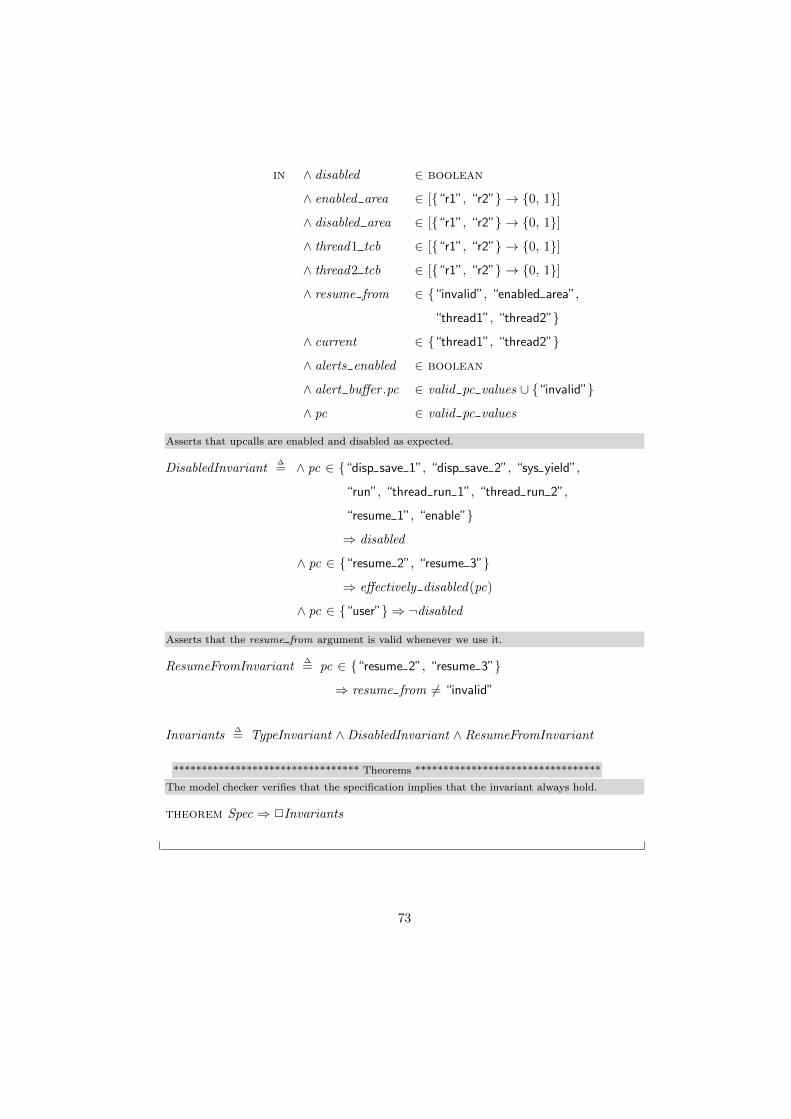
in ∧ disabled ∈ boolean
∧ enabled area ∈ [{“r1”, “r2”} → {0, 1}]
∧ disabled area ∈ [{“r1”, “r2”} → {0, 1}]
∧ thread1 tcb ∈ [{“r1”, “r2”} → {0, 1}]
∧ thread2 tcb ∈ [{“r1”, “r2”} → {0, 1}]
∧ resume from ∈ {“invalid”, “enabled area”,
“thread1”, “thread2”}
∧ current ∈ {“thread1”, “thread2”}
∧ alerts enabled ∈ boolean
∧ alert buffer .pc ∈ valid pc values ∪ {“invalid”}
∧ pc ∈ valid pc values
Asserts that upcalls are enabled and disabled as expected.
DisabledInvariant∆= ∧ pc ∈ {“disp save 1”, “disp save 2”, “sys yield”,
“run”, “thread run 1”, “thread run 2”,
“resume 1”, “enable”}
⇒ disabled
∧ pc ∈ {“resume 2”, “resume 3”}
⇒ effectively disabled(pc)
∧ pc ∈ {“user”} ⇒ ¬disabled
Asserts that the resume from argument is valid whenever we use it.
ResumeFromInvariant∆= pc ∈ {“resume 2”, “resume 3”}
⇒ resume from 6= “invalid”
Invariants∆= TypeInvariant ∧DisabledInvariant ∧ ResumeFromInvariant
********************************* Theorems *********************************
The model checker verifies that the specification implies that the invariant always hold.
theorem Spec ⇒ 2Invariants
73

Bibliography
[1] Effective Go. http://golang.org/doc/effective_go.html#concurrency.Accessed: 2014-09-17.
[2] The GCC low-level runtime library. https://gcc.gnu.org/onlinedocs/
gccint/Libgcc.html. Accessed: 2014-09-07.
[3] NAS parallel benchmarks. www.nas.nasa.gov/publications/npb.html. Ac-cessed: 2014-08-27.
[4] Advanced Micro Devices. Advanced Synchronization Facility - Proposed Archi-tectural Specification, March 2009. Revision 2.1.
[5] Advanced Micro Devices. AMD64 Architecture Programmer’s Manual - Volume2: System Programming, May 2013. Revision 3.23.
[6] Thomas E. Anderson, Brian N. Bershad, Edward D. Lazowska, and Henry M.Levy. Scheduler activations: Effective kernel support for the user-level man-agement of parallelism. In Proceedings of the Thirteenth ACM Symposium onOperating Systems Principles, 1991.
[7] ARM. ARM Dual-Timer Module (SP804) - Technical Reference Manual,January 2004. Revision r1p0 - Issue D.
[8] ARM. Cortex -A9 MPCore - Technical Reference Manual, July 2011. Revisionr3p0 - Issue G.
[9] ARM. Procedure Call Standard for the ARM Architecture, November 2012.ABI release 2.09.
[10] ARM. ARM Generic Interrupt Controller - Architecture Specification - Archi-tecture version 2.0, July 2013. Issue B.b.
[11] ARM. ARM Architecture Reference Manual - ARMv7-A and ARMv7-R edition,May 2014,. Issue C.c.
[12] Joe Armstrong, Robert Virding, Claes Wikstom, and Mike Williams. ConcurrentProgramming in Erlang. Prentice Hall, 2nd edition, 1996.
74

[13] Andrew Baumann. Inter-dispatcher communication in Barrelfish - Barrelfishtechnical note 11. Technical report, Systems Group, Department of ComputerScience, ETH Zurich, May 2011.
[14] Andrew Baumann, Paul Barham, Pierre-Evariste Dagand, Tim Harris, RebeccaIsaacs, Simon Peter, Timothy Roscoe, Adrian Schupbach, and Akhilesh Sing-hania. The multikernel: A new OS architecture for scalable multicore systems.In Proceedings of the 22nd ACM Symposium on OS Principles, 2009.
[15] Brian N. Bershad, Thomas E. Anderson, Edward D. Lazowska, and Henry M.Levy. User-level interprocess communication for shared memory multiprocessors.ACM Trans. Comput. Syst., May 1991.
[16] Nathan Binkert, Bradford Beckmann, Gabriel Black, Steven K. Reinhardt,Ali Saidi, Arkaprava Basu, Joel Hestness, Derek R. Hower, Tushar Krishna,Somayeh Sardashti, Rathijit Sen, Korey Sewell, Muhammad Shoaib, NilayVaish, Mark D. Hill, and David A. Wood. The gem5 simulator. SIGARCHComput. Archit. News, August 2011.
[17] Gabriel Black, Nathan Binkert, Steven K. Reinhardt, and Ali Saidi. ModularISA-independent full-system simulation. In Processor and System-on-ChipSimulation. Springer Publishing Company, Incorporated, 1st edition, 2010.chapter 5.
[18] Burton H. Bloom. Space/time trade-offs in hash coding with allowable errors.Commun. ACM, July 1970.
[19] Jamison D. Collins, Hong Wang, Dean M. Tullsen, Christopher Hughes, Yong-Fong Lee, Dan Lavery, and John P. Shen. Speculative precomputation: Long-range prefetching of delinquent loads. In Proceedings of the 28th AnnualInternational Symposium on Computer Architecture, 2001.
[20] Jonathan Corbet. The unveiling of kdbus. http://lwn.net/Articles/
580194/, January 2014. Accessed: 2014-09-17.
[21] Stephan Diestelhorst, Martin Nowack, Michael Spear, and Christof Fetzer. Briefannouncement: Between all and nothing - versatile aborts in hardware transac-tional memory. In Proceedings of the Twenty-fifth Annual ACM Symposium onParallelism in Algorithms and Architectures, 2013.
[22] G. Goumas, N. Anastopoulos, N. Koziris, and N. Ioannou. Overlapping compu-tation and communication in SMT clusters with commodity interconnects. InProceedings of the IEEE International Conference on Cluster Computing, Aug2009.
[23] Tim Harris, James Larus, and Ravi Rajwar. Transactional Memory. Morganand Claypool Publishers, 2nd edition, 2010.
[24] Samuel Hitz. Multicore ARMv7-a support for Barrelfish. ETH Zurich, 2012.Bachelor’s Thesis.
75

[25] IBM. A2 Processor User’s Manual for Blue Gene/Q, October 2012. Version1.3.
[26] IBM. Power ISA Version 2.07, May 2013.
[27] Intel Corporation. Intel R© 64 and IA-32 Architectures Optimization ReferenceManual, July 2013.
[28] Intel Corporation. Intel R© 64 and IA-32 Architectures Software Developer’sManual Volume 1: Basic Architecture, February 2014.
[29] Intel Corporation. Intel R© 64 and IA-32 Architectures Software Developer’sManual Volume 2B: Instruction Set Reference, N-Z, February 2014.
[30] Intel Corporation. Intel R© 64 and IA-32 Architectures Software Developer’sManual Volume 3B: System Programming Guide, Part 2, February 2014.
[31] Rebecca Isaacs. Message notifications - Barrelfish technical note 9. Technicalreport, Systems Group, Department of Computer Science, ETH Zurich, June2010.
[32] Norman P. Jouppi. Improving direct-mapped cache performance by the additionof a small fully-associative cache and prefetch buffers. In Proceedings of the17th Annual International Symposium on Computer Architecture, 1990.
[33] David Kanter. Analysis of Haswell’s transactional memory. http://www.
realworldtech.com/haswell-tm/, February 2012. Accessed: 2014-04-29.
[34] Leslie Lamport. Specifying Systems: The TLA+ Language and Tools forHardware and Software Engineers. Addison-Wesley Longman Publishing Co.,Inc., 2002.
[35] Paul E. McKenney. Memory barriers: a hardware view for software hackers,July 2010.
[36] Message Passing Interface Forum. MPI: A Message-Passing Interface Standard- Version 3.0, September 2012.
[37] Ravi Rajwar and James R. Goodman. Speculative lock elision: Enablinghighly concurrent multithreaded execution. In Proceedings of the 34th AnnualACM/IEEE International Symposium on Microarchitecture, 2001.
[38] Carl G. Ritson and Frederick R.M. Barnes. An evaluation of Intel’s restrictedtransactional memory for CPAs. In Communicating Process Architectures, 2013.
[39] Michael F. Spear, Arrvindh Shriraman, Luke Dalessandro, Sandhya Dwarkadas,and Michael L. Scott. Nonblocking transactions without indirection usingalert-on-update. In Proceedings of the Nineteenth Annual ACM Symposium onParallel Algorithms and Architectures, 2007.
[40] Michael F. Spear, Arrvindh Shriraman, Hemayet Hossain, Sandhya Dwarkadas,and Michael L. Scott. Alert-on-update: A communication aid for shared memory
76
multiprocessors (poster paper). In Proceedings of the 12th ACM SIGPLANSymposium on Principles and Practice of Parallel Programming, 2007.
[41] Sayantan Sur, Matthew J. Koop, and Dhabaleswar K. Panda. High-performanceand scalable MPI over InfiniBand with reduced memory usage: An in-depthperformance analysis. In Proceedings of the 2006 ACM/IEEE Conference onSupercomputing, 2006.
[42] Nathan Tuck and Dean M. Tullsen. Initial observations of the simultaneousmultithreading Pentium 4 processor. In Proceedings of the 12th InternationalConference on Parallel Architectures and Compilation Techniques, 2003.
[43] Hong Wang, Perry H. Wang, Ross Dave Weldon, Scott M. Ettinger, HidekiSaito, Milind Girkar, Steve Shih-wei Liao, and John P. Shen. Speculative pre-computation: Exploring the use of multithreading for latency. Intel TechnologyJournal Q1, (Vol. 6 Issue 1), 2002.
[44] Yuan Yu, Panagiotis Manolios, and Leslie Lamport. Model checking TLA+specifications. In Proceedings of the 10th IFIP WG 10.5 Advanced ResearchWorking Conference on Correct Hardware Design and Verification Methods,CHARME ’99, 1999.
[45] Gerd Zellweger, Simon Gerber, Kornilios Kourtis, and Timothy Roscoe. De-coupling cores, kernels, and operating systems. In 11th USENIX Symposiumon Operating Systems Design and Implementation (OSDI 14), 2014.
77

Eigenständigkeitserklärung Die unterzeichnete Eigenständigkeitserklärung ist Bestandteil jeder während des Studiums verfassten Semester-, Bachelor- und Master-Arbeit oder anderen Abschlussarbeit (auch der jeweils elektronischen Version). Die Dozentinnen und Dozenten können auch für andere bei ihnen verfasste schriftliche Arbeiten eine Eigenständigkeitserklärung verlangen.
__________________________________________________________________________ Ich bestätige, die vorliegende Arbeit selbständig und in eigenen Worten verfasst zu haben. Davon ausgenommen sind sprachliche und inhaltliche Korrekturvorschläge durch die Betreuer und Betreuerinnen der Arbeit. Titel der Arbeit (in Druckschrift):
Verfasst von (in Druckschrift):
Bei Gruppenarbeiten sind die Namen aller Verfasserinnen und Verfasser erforderlich.
Name(n): Vorname(n):
Ich bestätige mit meiner Unterschrift:
− Ich habe keine im Merkblatt „Zitier-Knigge“ beschriebene Form des Plagiats begangen.
− Ich habe alle Methoden, Daten und Arbeitsabläufe wahrheitsgetreu dokumentiert.
− Ich habe keine Daten manipuliert.
− Ich habe alle Personen erwähnt, welche die Arbeit wesentlich unterstützt haben.
Ich nehme zur Kenntnis, dass die Arbeit mit elektronischen Hilfsmitteln auf Plagiate überprüft werden kann. Ort, Datum Unterschrift(en)
Bei Gruppenarbeiten sind die Namen aller Verfasserinnen und
Verfasser erforderlich. Durch die Unterschriften bürgen sie gemeinsam für den gesamten Inhalt dieser schriftlichen Arbeit.
Hardware Transactional Memory and Message Passing
Fuchs Raphael
Zürich, 19. September 2014