in-depth survey report: control technology … · boilermaker's national apprenticeship...
TRANSCRIPT

In-Depth Survey Report:
Control Technology Assessment for the Welding Operations
at
Boilermaker's National Apprenticeship Training School Kansas City, Kansas
REPORT WRITTEN BY: Marjorie E. Wallace Thomas Fischbach Ronald J. Kovein
REPORT DATE: June 27, 1997
REPORT NO.: ECTB 214-13a
U.S. DEPARTMENT OF HEALTH AND HUMAN SERVICES Public Health Service
Centers for Disease Control and Prevention National Institute for Occupational Safety and Health
Division of Physical Sciences and Engineering 4676 Columbia Parkway - R5
Cincinnati, Ohio 45226
PLANT SURVEYED: Boilermaker's National Apprenticeship Training School 1017 N. 9th Street Kansas City, Kansas 66101
SIC CODE: 8249
SURVEY DATE: April 22-26, 1996
SURVEY CONDUCTED BY: Marjorie Edmonds Wallace Ronald J. Kovein Daniel S. Watkins
EMPLOYER REPRESENTATIVES Louie Lombardi
CONTACTED: Lead Welding Instructor John Standish Welding Instructor
Mike Blood Welding Instructor Paul Ross Union Welder Glenn Tubbs Business Manager, Local 83 Roger Erickson Business Representative, Lodge 83
OTHER REPRESENTATIVES Pam Susi
CONTACTED: Center to Protect Workers' Rights Bob Dinsmore Plymovent, Inc.
ANALYTICAL SERVICES: DataChem Laboratories Salt Lake City, Utah
MANUSCRIPT PREPARATION: Bernice L. Clark
DISCLAIMER Mention of company names or products does not constitute endorsement by the Centers for Disease Control and Prevention. TABLE OF CONTENTS SUMMARY INTRODUCTION PROJECT OVERVIEW SITE SPECIFIC OVERVIEW WELDING HAZARDS EVALUATION CRITERIA STUDY PLAN SAMPLING METHODOLOGY INTEGRATED SAMPLING Short Term Sampling Full Term Sampling Analysis INSTRUMENTAL MONITORING
Real-Time Total Welding Fume Concentration Data Real-Time Total Welding Fume Particle Count Data VENTILATION MEASUREMENTS GAS MEASUREMENTS RESULTS AND DISCUSSION VENTILATION DATA GAS SAMPLING RESULTS INTEGRATED SAMPLING RESULTS Total Welding Fume Analysis Elemental Analysis Hexavalent Chromium Analysis REAL-TIME DATA RESULTS EFFECT OF VENTILATION ON FUME EXPOSURES WHEN WELDING INDOORS CONCLUSIONS AND RECOMMENDATIONS REFERENCES APPENDICES A: NIOSH BACKGROUND B: POTENTIAL HEALTH HAZARDS C: SUMMARY OF SELECTED OCCUPATIONAL EXPOSURE LIMITS D: ANALYTICAL DETECTION AND QUANTITATION LIMITS E: GRAVIMETRIC AIR SAMPLING DATA F: ELEMENTAL AIR SAMPLING DATA G: HEXAVALENT CHROMIUM AIR SAMPLING DATA SUMMARY The Engineering Control Technology Branch of the National Institute for Occupational Safety and Health is currently conducting a study of welding operations and workers' exposures to welding fumes. The goal of this study is to identify, observe, and evaluate engineering control measures which may reduce the amount of fume a worker is exposed to during welding. At the conclusion of this study, information on effective control technology will be disseminated to the welding community. This report summarizes the results of an in-depth sampling study conducted on the welding operations at the Boilermaker's National Apprenticeship Training School. The goals of the study were to measure fume exposures during stainless steel welding, using different rod types and rod diameters, and to evaluate the effect of local exhaust ventilation during outdoor welding operations. During this study, shielded metal arc (or stick) welding techniques were evaluated, primarily in a semi-enclosed tank located outside the school. Four standard types of stainless steel rods used by the Boilermaker's were identified and evaluated: AWS 308, 309-16, 316, and 347. The 3xx series designated by the American Welding Society (AWS) have a high chromium-nickel makeup. Four standard rod diameters used by the Boilermaker's were also identified and evaluated: 3/32", 1/8", 5/32", and 3/16". The rods were from a number of manufacturers, including Alloy Rods, Harris Welco Alloys, McKay, Tech Alloy, and Lincoln. Two local exhaust ventilation units were evaluated during this study, a mobile fume extractor with a 2 meter arm and a portable fan unit with a similar exhaust arm. Both units were provided by Plymovent. Gravimetric samples were collected and analyzed for total welding fume levels and for welding fume constituent levels. Additional samples were collected for hexavalent chromium. Real-time data was collected on relative concentrations using aerosol photometers and particle counters. Gas levels were determined for NO2, CO and O2.
Results indicated that welders were overexposed to stainless steel welding fume, hexavalent chromium, arsenic, total chromium, iron, manganese, and nickel. Local exhaust ventilation helped to reduce these levels but not to a point where the exposures were considered to be completely controlled. The effect of wind and the position of the welder may have been extremely detrimental to the ability of the local exhaust ventilation at controlling welding fume exposures. INTRODUCTION PROJECT OVERVIEW Over the past twenty years, the National Institute for Occupational Safety and Health (NIOSH) has recognized the importance of preventing potential health hazards associated with fumes and gases generated during welding operations (see Appendix A); however, no comprehensive study of control technology for welding operations has been conducted since the late 70s. As such, the Engineering Control Technology Branch (ECTB) of NIOSH is currently conducting a study to evaluate the effectiveness of engineering control measures in reducing welding fume exposures. This welding assessment study was initiated for several reasons. First, even with advances in control technology, welders continue to be exposed to hazardous welding fumes and gases.1 Second, the continual development and implementation of new welding processes, techniques, and materials can result in unidentified and uncontrolled health hazards. Third, many welding operations are small shops that may not have access to current technology for the control of welding emissions; this project responds to the NIOSH small business initiative which identifies welding shops as one of the top ten hazardous small businesses, in terms of occupational health risks.2 Finally, as it is likely that welding will be a high priority for OSHA over the next few years,3 industry will need timely research on engineering technology for the control of welding fumes and gases. Many sites use a combination of ventilation and respiratory protection equipment to try and control the amount of fumes (and gases) the welder is exposed to during welding operations. If the ventilation system does not adequately control the fumes, the welder often relies heavily on the respirator for protection against potential health hazards. Ideally, respiratory protection should be used only as a last resort against welding fumes and only when an appropriate respiratory protection program is in place. It is unclear whether strong respiratory protection programs are common in welding shops. Therefore, the goals of this assessment study are to identify effective ventilation systems, or other engineering control measures, that will protect the welder's health, and to disseminate this information to the welding community. SITE SPECIFIC OVERVIEW In January 1995, the Hazard Evaluation and Technical Assistance Branch (HETAB) of NIOSH received numerous requests from building and construction trade unions requesting evaluations of stainless steel welding fumes. Aware of ECTB's ongoing welding project, HETAB requested engineering assistance on the control of stainless steel welding fumes during boiler rehab work. To determine exposure levels and effective controls, ECTB needed to evaluate various systems and processes in the field. The Boilermakers' Union offered to participate in a simulation study where they would provide welders and welding equipment and consumables at their training facility in Kansas City, Kansas. Two types of portable local exhaust ventilation units, supplied by Plymovent (Mississauga, Ontario), were evaluated for their ability to exhaust stainless steel welding fumes and gases away from the worker's breathing zone, at the point of generation. The ventilation units were tested both inside a building and outside in a semi-enclosed tank. Process variables, such as the welding rod type and diameter, were also evaluated to determine their effect on welding fume levels. WELDING HAZARDS The effect of welding fumes and gases on a welder's health can vary depending on such factors as the length and intensity of the exposure and the specific toxic metals involved. Welding processes involving stainless steel, cadmium- or lead-coated steel, or metals such as nickel, chrome, zinc, and copper are particularly hazardous as the fumes produced are considerably more toxic than those encountered when welding mild steel. Mild steel consists mainly of iron, carbon, and small amounts of manganese, phosphorous, sulfur, and silicon, while stainless
steel contains mainly iron, chromium, nickel, titanium, and manganese.4 The NIOSH criteria document identifies arsenic, beryllium, cadmium, chromium (VI), and nickel as potential human carcinogens that may be present in welding fumes. Epidemiological studies and case reports of workers exposed to welding emissions have shown an excessive incidence of acute and chronic respiratory diseases. Welder respiratory ailments can include occupational asthma, siderosis, emphysema, chronic bronchitis, fibrosis of the lung, and lung cancer. Epidemiological evidence indicates that welders generally have a 40 percent increase in relative risk of developing lung cancer as a result of their work.4 Other cancers associated with welding include leukemia, cancer of the stomach, brain, nasal sinus, and pancreas. Cadmium poisoning can affect the respiratory system and damage the liver and kidneys. A common reaction to overexposure to metal fumes, particularly zinc oxide fumes, is metal fume fever, with symptoms resembling the flu. Other health hazards during welding can include vision problems and dermatitis arising from ultraviolet radiation exposures, burns, and musculoskeletal stress from awkward work positions.4 See Appendix B for additional information on potential health hazards from welding. EVALUATION CRITERIA As a guide when evaluating hazards posed by workplace exposures such as those from welding, NIOSH field staff employ environmental evaluation criteria. These criteria are intended to suggest levels of exposure to which most workers may be exposed up to 10 hours per day, 40 hours per week for a working lifetime without experiencing adverse health effects. It is, however, important to note that not all workers will be protected from adverse health effects even if their exposures are maintained below these levels. A small percentage may experience adverse health effects due to individual susceptibility, a preexisting medical condition, and/or a hypersensitivity (allergy). In addition, some hazardous substances may act in combination with other workplace exposures, the general environment, or with medications or personal habits of the worker to produce health effects even if the occupational exposures are controlled at the level set by evaluation criteria. These combined effects are often not considered in the evaluation criteria. Also, some substances are absorbed by direct contact with the skin and mucous membranes, and thus potentially increase the overall exposure. Finally, evaluation criteria may change over the years as new information on the toxic effects of an agent become available. The primary sources of environmental evaluation criteria in the United States that can be used for the workplace are: (1) the U.S. Department of Labor (OSHA) Permissible Exposure Limits (PELs); (2) NIOSH Recommended Exposure Limits (RELs); and (3) the American Conference of Governmental Industrial Hygienists's (ACGIH) Threshold Limit Values (TLVs). The OSHA PELs are required to consider the feasibility of controlling exposures in various industries where the agents are used; the NIOSH RELs, by contrast, are based primarily on concerns relating to the prevention of occupational disease. ACGIH Threshold Limit Values (TLVs) refer to airborne concentrations of substances and represent conditions under which it is believed that nearly all workers may be repeatedly exposed day after day without adverse health effects. ACGIH states that the TLVs are guidelines. The ACGIH is a private, professional society. It should be noted that industry is legally required to meet only those levels specified by OSHA PELs. In 1989, the OSHA PEL for total welding fume was set at 5 mg/m3 (5000 µg/m3) as an 8-hour time-weighted average (TWA); however, this limit was vacated and currently is not enforceable. Since 1989, OSHA has not reestablished a PEL for total welding fume; however, individual PELs have been set for the various constituents which can be found in welding fumes (see Appendix C).5 OSHA has also set a PEL for total particulate not otherwise regulated (PNOR) at 15 mg/m3 as an 8-hour time-weighted average (TWA). A TWA exposure refers to the average airborne concentration of a substance during a normal 8- to 10-hour workday. Some substances have recommended short-term exposure limits (STEL) or ceiling values that are intended to supplement the TWA where there are recognized toxic effects from high, short-term exposures. The ACGIH has set a TLV-TWA for welding fumes-total particulate (NOC) at 5 mg/m3. The ACGIH recommends that conclusions based on total fume concentration are generally adequate if no toxic elements are present in the welding rod, metal, or metal coating and if conditions are not conducive to the formation of toxic gases.6 NIOSH indicates that it is not possible to establish an exposure limit for total welding emissions since the composition of welding fumes and gases vary greatly, and the welding constituents may interact to produce adverse health effects. Therefore, NIOSH suggests that the exposure limits set for each welding fume constituent
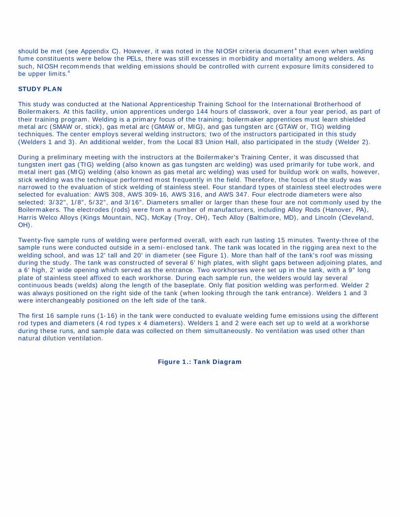
should be met (see Appendix C). However, it was noted in the NIOSH criteria document4 that even when welding fume constituents were below the PELs, there was still excesses in morbidity and mortality among welders. As such, NIOSH recommends that welding emissions should be controlled with current exposure limits considered to be upper limits.4 STUDY PLAN This study was conducted at the National Apprenticeship Training School for the International Brotherhood of Boilermakers. At this facility, union apprentices undergo 144 hours of classwork, over a four year period, as part of their training program. Welding is a primary focus of the training; boilermaker apprentices must learn shielded metal arc (SMAW or, stick), gas metal arc (GMAW or, MIG), and gas tungsten arc (GTAW or, TIG) welding techniques. The center employs several welding instructors; two of the instructors participated in this study (Welders 1 and 3). An additional welder, from the Local 83 Union Hall, also participated in the study (Welder 2). During a preliminary meeting with the instructors at the Boilermaker's Training Center, it was discussed that tungsten inert gas (TIG) welding (also known as gas tungsten arc welding) was used primarily for tube work, and metal inert gas (MIG) welding (also known as gas metal arc welding) was used for buildup work on walls, however, stick welding was the technique performed most frequently in the field. Therefore, the focus of the study was narrowed to the evaluation of stick welding of stainless steel. Four standard types of stainless steel electrodes were selected for evaluation: AWS 308, AWS 309-16, AWS 316, and AWS 347. Four electrode diameters were also selected: 3/32", 1/8", 5/32", and 3/16". Diameters smaller or larger than these four are not commonly used by the Boilermakers. The electrodes (rods) were from a number of manufacturers, including Alloy Rods (Hanover, PA), Harris Welco Alloys (Kings Mountain, NC), McKay (Troy, OH), Tech Alloy (Baltimore, MD), and Lincoln (Cleveland, OH). Twenty-five sample runs of welding were performed overall, with each run lasting 15 minutes. Twenty-three of the sample runs were conducted outside in a semi-enclosed tank. The tank was located in the rigging area next to the welding school, and was 12' tall and 20' in diameter (see Figure 1). More than half of the tank's roof was missing during the study. The tank was constructed of several 6' high plates, with slight gaps between adjoining plates, and a 6' high, 2' wide opening which served as the entrance. Two workhorses were set up in the tank, with a 9" long plate of stainless steel affixed to each workhorse. During each sample run, the welders would lay several continuous beads (welds) along the length of the baseplate. Only flat position welding was performed. Welder 2 was always positioned on the right side of the tank (when looking through the tank entrance). Welders 1 and 3 were interchangeably positioned on the left side of the tank. The first 16 sample runs (1-16) in the tank were conducted to evaluate welding fume emissions using the different rod types and diameters (4 rod types x 4 diameters). Welders 1 and 2 were each set up to weld at a workhorse during these runs, and sample data was collected on them simultaneously. No ventilation was used other than natural dilution ventilation.
Figure 1.: Tank Diagram
The next seven sample runs (17-23) were conducted in the tank to evaluate the local exhaust ventilation (LEV) units. Welder 2 participated in all seven of these runs. Welder 1 welded simultaneously with Welder 2 during one of the seven runs, while Welder 3 welded simultaneously with Welder 2 during another three of the runs. The LEV units evaluated during these sample runs were selected from four units supplied by Plymovent Canada (Mississauga, Ontario):
Unit 1: MEF - Mobile, wheeled fume extractor unit with a 6.56' (2 m) flexible arm Unit 2: BSFM-2101 - Portable fan unit, on a support stand, with a flexible arm Unit 3: TK-400 - Portable filter with suction hoses and nozzles Unit 4: MK-800/3 - Mobile mechanical filter unit with a 9.84' (3 m) extraction arm.
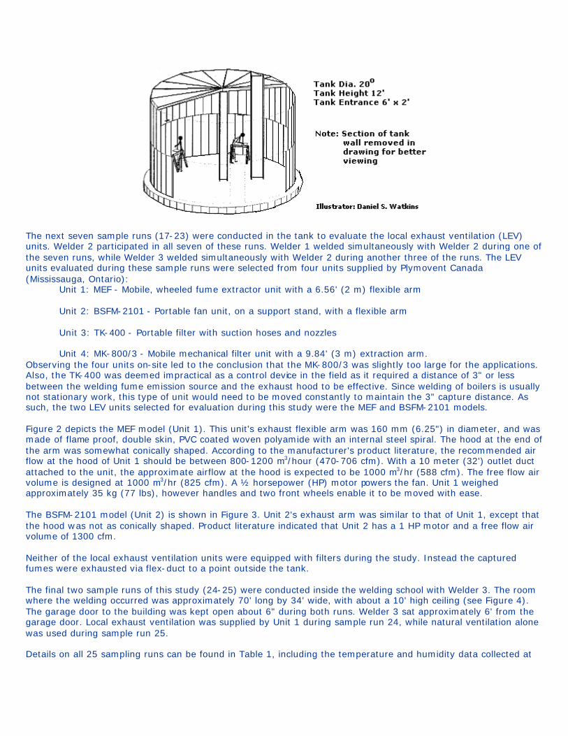
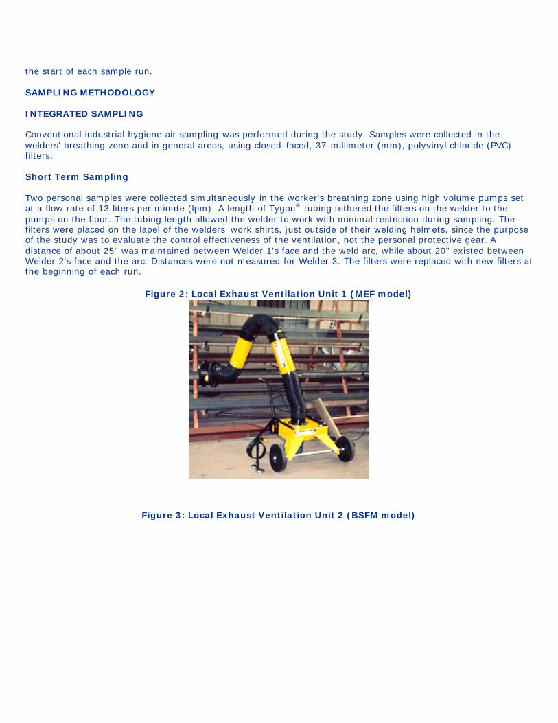
Observing the four units on-site led to the conclusion that the MK-800/3 was slightly too large for the applications. Also, the TK-400 was deemed impractical as a control device in the field as it required a distance of 3" or less between the welding fume emission source and the exhaust hood to be effective. Since welding of boilers is usually not stationary work, this type of unit would need to be moved constantly to maintain the 3" capture distance. As such, the two LEV units selected for evaluation during this study were the MEF and BSFM-2101 models. Figure 2 depicts the MEF model (Unit 1). This unit's exhaust flexible arm was 160 mm (6.25") in diameter, and was made of flame proof, double skin, PVC coated woven polyamide with an internal steel spiral. The hood at the end of the arm was somewhat conically shaped. According to the manufacturer's product literature, the recommended air flow at the hood of Unit 1 should be between 800-1200 m3/hour (470-706 cfm). With a 10 meter (32') outlet duct attached to the unit, the approximate airflow at the hood is expected to be 1000 m3/hr (588 cfm). The free flow air volume is designed at 1000 m3/hr (825 cfm). A ½ horsepower (HP) motor powers the fan. Unit 1 weighed approximately 35 kg (77 lbs), however handles and two front wheels enable it to be moved with ease. The BSFM-2101 model (Unit 2) is shown in Figure 3. Unit 2's exhaust arm was similar to that of Unit 1, except that the hood was not as conically shaped. Product literature indicated that Unit 2 has a 1 HP motor and a free flow air volume of 1300 cfm. Neither of the local exhaust ventilation units were equipped with filters during the study. Instead the captured fumes were exhausted via flex-duct to a point outside the tank. The final two sample runs of this study (24-25) were conducted inside the welding school with Welder 3. The room where the welding occurred was approximately 70' long by 34' wide, with about a 10' high ceiling (see Figure 4). The garage door to the building was kept open about 6" during both runs. Welder 3 sat approximately 6' from the garage door. Local exhaust ventilation was supplied by Unit 1 during sample run 24, while natural ventilation alone was used during sample run 25. Details on all 25 sampling runs can be found in Table 1, including the temperature and humidity data collected at
the start of each sample run. SAMPLING METHODOLOGY INTEGRATED SAMPLING Conventional industrial hygiene air sampling was performed during the study. Samples were collected in the welders' breathing zone and in general areas, using closed-faced, 37-millimeter (mm), polyvinyl chloride (PVC) filters. Short Term Sampling Two personal samples were collected simultaneously in the worker's breathing zone using high volume pumps set at a flow rate of 13 liters per minute (lpm). A length of Tygon® tubing tethered the filters on the welder to the pumps on the floor. The tubing length allowed the welder to work with minimal restriction during sampling. The filters were placed on the lapel of the welders' work shirts, just outside of their welding helmets, since the purpose of the study was to evaluate the control effectiveness of the ventilation, not the personal protective gear. A distance of about 25" was maintained between Welder 1's face and the weld arc, while about 20" existed between Welder 2's face and the arc. Distances were not measured for Welder 3. The filters were replaced with new filters at the beginning of each run.
Figure 2: Local Exhaust Ventilation Unit 1 (MEF model)
Figure 3: Local Exhaust Ventilation Unit 2 (BSFM model)
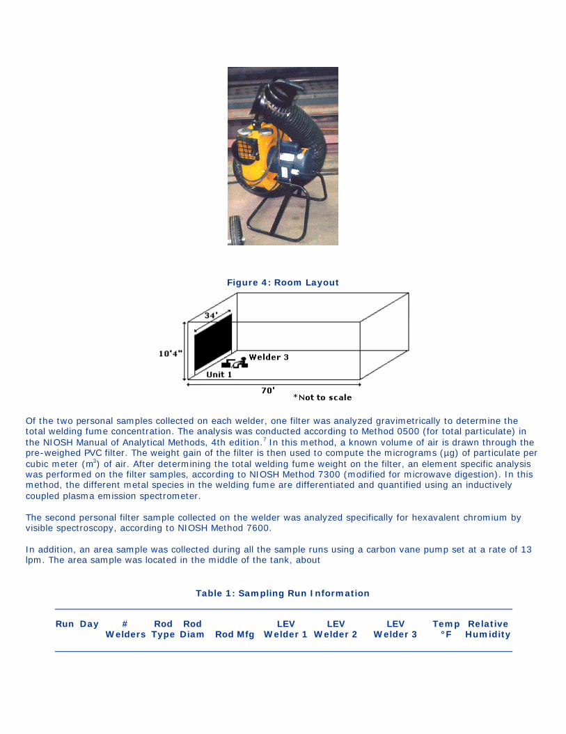
Figure 4: Room Layout
Of the two personal samples collected on each welder, one filter was analyzed gravimetrically to determine the total welding fume concentration. The analysis was conducted according to Method 0500 (for total particulate) in the NIOSH Manual of Analytical Methods, 4th edition.7 In this method, a known volume of air is drawn through the pre-weighed PVC filter. The weight gain of the filter is then used to compute the micrograms (µg) of particulate per cubic meter (m3) of air. After determining the total welding fume weight on the filter, an element specific analysis was performed on the filter samples, according to NIOSH Method 7300 (modified for microwave digestion). In this method, the different metal species in the welding fume are differentiated and quantified using an inductively coupled plasma emission spectrometer. The second personal filter sample collected on the welder was analyzed specifically for hexavalent chromium by visible spectroscopy, according to NIOSH Method 7600. In addition, an area sample was collected during all the sample runs using a carbon vane pump set at a rate of 13 lpm. The area sample was located in the middle of the tank, about
Table 1: Sampling Run Information
Run Day #
Welders Rod Type
Rod Diam
Rod Mfg
LEV Welder 1
LEV Welder 2
LEV Welder 3
Temp °F
Relative Humidity
1 4/23 2 308 3/32" Alloy Rods None None - 55 38%
2 4/23 2 309 3/32" Welco None None - - -
3 4/23 2 316 3/32" McKay None None - 69.2 22%
4 4/23 2 347 3/32" Welco None None - 70 22%
5 4/23 2 308 1/8" Alloy Rods None None - 71 22%
6 4/23 2 309 1/8" Weldco None None - 72.6 20%
7 4/23 2 316 1/8" Lincoln None None - 73.3 21%
8 4/23 2 347 1/8" McKay None None - 72.9 21%
9 4/24 2 308 5/32" McKay None None - 63.3 33%
10 4/24 2 309 5/32" McKay None None - 62.8 38%
11 4/24 2 316 5/32" McKay None None - 63.7 37%
12 4/24 2 347 5/32" McKay None None - 66 37%
13 4/24 2 308 3/16" McKay None None - 67.9 36%
14 4/24 2 309 3/16" McKay None None - 70 34%
15 4/24 2 316 3/16" McKay None None - 81.2 26%
16 4/24 2 347 3/16" McKay None None - 83 23%
17 4/24 2 308 3/16" McKay Unit 2 None - 84.7 22%
18 4/25 1 308 3/16" Alloy Rods - Unit 2 - 68.4 46%
19 4/25 1 308 3/16" Alloy Rods - Unit 1 - 67.9 39%
20 4/25 1 308 3/16" Alloy Rods - None - 68.8 34%
21 4/25 2 308 3/16" Alloy Rods - Unit 1 Unit 2 - 9 min 69.4 25%
22 4/25 2 308 3/16" Alloy Rods - Unit 1 Unit 2 71.3 22%
23 4/25 2 347 3/16" McKay - Unit 1 Unit 2 - -
24 4/25 1 308 3/16" Tech Alloy - - Unit 1 - -
25 4/25 1 308 3/16" Tech Alloy - - None - -
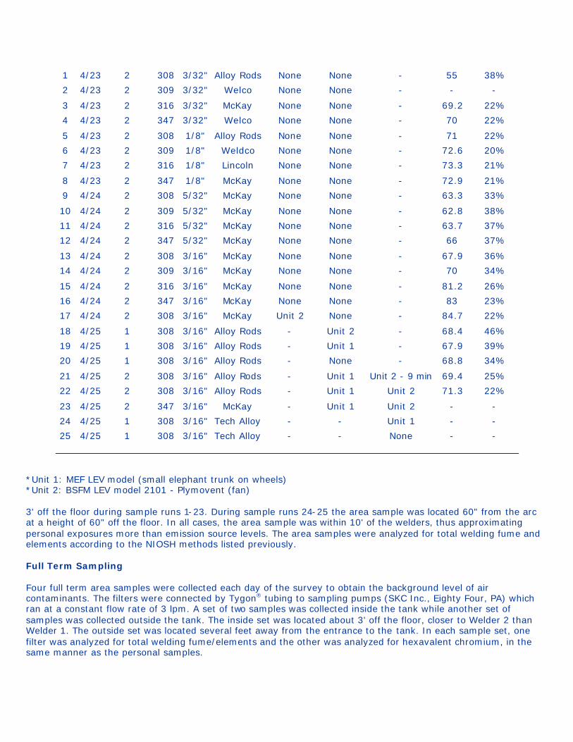
*Unit 1: MEF LEV model (small elephant trunk on wheels) *Unit 2: BSFM LEV model 2101 - Plymovent (fan) 3' off the floor during sample runs 1-23. During sample runs 24-25 the area sample was located 60" from the arc at a height of 60" off the floor. In all cases, the area sample was within 10' of the welders, thus approximating personal exposures more than emission source levels. The area samples were analyzed for total welding fume and elements according to the NIOSH methods listed previously. Full Term Sampling Four full term area samples were collected each day of the survey to obtain the background level of air contaminants. The filters were connected by Tygon® tubing to sampling pumps (SKC Inc., Eighty Four, PA) which ran at a constant flow rate of 3 lpm. A set of two samples was collected inside the tank while another set of samples was collected outside the tank. The inside set was located about 3' off the floor, closer to Welder 2 than Welder 1. The outside set was located several feet away from the entrance to the tank. In each sample set, one filter was analyzed for total welding fume/elements and the other was analyzed for hexavalent chromium, in the same manner as the personal samples.
Analysis For each of the analyses, there is a limit of detection (LOD) and a limit of quantitation (LOQ). The LOD refers to the lowest measurable amount on the filter while the LOQ refers to the level at which the laboratory can confidently report precise results. Appendix D lists the limits of detection and quantification for all the elements analyzed by the laboratory. INSTRUMENTAL MONITORING Video exposure monitoring was used to study in greater detail how specific tasks affected the worker's exposure to air contaminants.8,9 Real-Time Total Welding Fume Concentration Data To collect personal sampling data, an aerosol photometer, the Hand-held Aerosol Monitor (HAM) (PPM Inc., Knoxville, TN), was positioned on one welder's chest using a belt and harness. During the first 17 sample runs, the HAM was worn by Welder 1. During runs 18-23, Welder 2 wore the HAM, and during runs 24 and 25, Welder 3 wore the HAM. A personal pump operating at 3 lpm was used to draw air through the HAM's sensing chamber. A filter cassette was mounted on the HAM to collect the welding fume before it reached the pump. This filter cassette was analyzed for total welding fume and elements in the same manner as the other filter samples. Only one filter was used per day on the HAM. Another HAM was used to collect area sampling data. This HAM was positioned on the wall of the tank, close to Welder 2's work area, at a height of 6'. The distance between the area HAM and the welding arc of Welder 2 was noted to be about 58". For runs 24 and 25, inside the building, the area HAM was located 18" above the floor, 95" from the center of the baseplate. Due to pump shortages, the area HAM was maintained as a passive sampling device, so no filter was used. The HAM operates such that it emits a light from a light-emitting diode. This light is scattered by the aerosol and forward-scattered light is detected. The amount of scattered light is proportional to the analog output of the HAM. However, the calibration of the HAM varies with aerosol properties such as refractive index and particle size.8 Therefore, HAM measurements are often expressed as "relative exposures" or "the HAM analog output", with units of volts. During the first run, the personal HAM was set at a sensitivity level of 20 mg/m3 with a one second averaging time constant. Using this sensitivity level, the analog output of one volt was equated to a total welding fume concentration of 10 mg/m3 for a calibration dust. After observing the amount of fume generated during the first run, the sensitivity level was changed to 200 mg/m3 which equates to a total welding fume concentration of 100 mg/m3 per volt. This prevented the personal HAM from "peaking out" during the data collection. The area HAM was set at a sensitivity level of 2 mg/m3, equating to a total welding fume concentration of 1 mg/m3 per volt. The analog output of the HAMs was recorded by Metrosonics data loggers (Model dl-3200, Metrosonics, Inc., Rochester, NY). When the data collection was completed, the data loggers were downloaded to a personal computer for storage and analysis. The workers' activities were simultaneously recorded on video for use in a detailed task analysis of the welding operations. Real-Time Total Welding Fume Particle Count Data Optical particle counters (Model 227, Met One, Grants Pass, OR) were also used to obtain information on aerosol concentrations on the welders and in the general area. When used as a personal sampler, the instrument was clipped onto one welder's belt and the inlet was positioned in his breathing zone. Welder 1 wore the Met One during the first 17 sample runs. Welder 2 wore the Met One during runs 18-23, and Welder 3 wore the Met One during runs 24-25. A 30-cm length of 5-mm inside diameter Tygon® tubing was used to transport the aerosol from the sensor to the instrument. To monitor total welding fume particle counts in the tank, a second Met One was placed on the tank wall, close to Welder 1's work area, at a height of 6' 6". A distance of about 65" was noted between the area Met One and
Welder 1's welding arc. After the first 17 runs, the area Met One was moved closer to Welder 2, where it was positioned next to the area HAM, at a distance of 51" from the center of the baseplate. The Met One remained in this position for sample runs 18-20 while Welder 2 was the only person welding. Then, when Welder 3 joined Welder 2, during sample runs 21-23, the Met One was moved back to its original position. For sample runs 24 and 25, inside the building, the area Met One was located 18" off the floor, at a point 95" from the center of the baseplate (next to the area HAM). The Met One instruments continuously record the number of particles counted during a series of consecutive sampling periods. During this study, a sampling rate of 2.83 lpm, a sampling period of one minute, and a time between sampling periods of one second were set. Two channels were used to store the number of particle counts in a time interval. One channel stored the total number of particles counted greater than 0.3 µm. The second channel was set to count the number of particles larger than 3.0 µm. The particles were sized, based upon the amount of scattered light detected by the photo detector. In reality, the magnitude of the light pulse scattered by the particles varies with particle size, optical properties, and surface roughness. The stored data was downloaded directly to the computer to obtain the particle counts for each sampling period. (According to the instrument manufacturer, the recorded time of the sample was the end time of the sampling segment.) This data could then be correlated with the videotape to determine relationships between events and exposures. VENTILATION MEASUREMENTS The ventilation systems were assessed by measuring capture and face velocities with a hot wire anemometer (TSI VelociCalc). This instrument measures air velocities in feet-per-minute (fpm) and air volumes in cubic feet-per-minute (cfm). Capture velocities were measured to determine the ability of the system to remove welding fumes at certain distances away from the fume generation source. The capture velocity is the velocity necessary to overcome opposing air currents, thus allowing the welding fume to be exhausted. Face velocities were measured to compute air volumes. Work methods regarding welding techniques and the use of the ventilation systems were observed. In addition, airflow patterns around the workers during welding were observed using smoke tubes and aspirators. From this, an understanding of how air contaminants are transported into the worker's breathing zone can be developed. GAS MEASUREMENTS Measurements were collected during each sample run for NO2, CO, and O2, using a PhD Ultra Multi Gas Detector (Biosystems, Inc., Rockfall, CT ). Temperature and relative humidity measurements were collected using a thermohygrometer. RESULTS AND DISCUSSION It should be noted that several study parameters could not be held constant and these factors may have influenced the data results. The parameters include worker habits, wind/air currents, and temperature and humidity fluctuations. Observations regarding each of these parameters are discussed below. The welders work habits were all somewhat different. Welder 1 stood fairly erect with his face positioned directly over the base plate. Welder 2 also stood, but bent over at the waist when welding, resting his arms on the workhorse, and keeping his face angled slightly away from the weld area. Welder 3 sat on a stool when welding. Welders 1 and 2 were right handed; Welder 3 was left handed. The welders worked at approximately the same rate, using about the same number of electrodes during a single run. Throughout the survey, the total number of electrodes used by each welder during a sample run fluctuated between 10 and 21. This was primarily dependent upon the diameter of the electrode; as the diameter increased, the number of rods used during the 15 minute run decreased. The effect of the wind was not well documented. During Runs 3 and 9 the air current appeared to be directed towards Welder 2, while during Runs 4 and 7 it appeared to be directed towards Welder 1. The second day of sampling appeared to be slightly windier than the first day. On the third day of sampling, a length of fabric was fastened to a nail on the tank wall near Worker 2 to serve as a makeshift indicator of the wind direction. During

Runs 18 and 19, the wind was mostly blowing towards the left side of the tank, directly into Welder 2's face. During run 21, the wind appeared to mostly blow towards the right side of the tank, and during runs 20, 22, and 23 the wind was intermittently blowing towards either side of the tank. Air velocities inside the tank were generally measured between 20-40 fpm, but occasional gusts were felt. As mentioned previously, temperature and relative humidity measurements are shown in Table 1 for each sampling run. During the first day of sampling, a peak temperature of 73.3°F and a peak humidity level of 38 percent were measured. Peaks on the second day of sampling were at 84.7°F and 38 percent RH, while on the third day the peaks were 71.3°F and 46 percent RH. Typically, as the day progressed, the temperature increased and the humidity decreased. VENTILATION DATA The LEV units were positioned 3" away from the end of the 9" long base plate. Face velocities were not measured on Unit 1. However, a face velocity of 1820 fpm was measured at the midpoint of the hood face of Unit 2. This computes to an airflow of about 390 cfm with the exhaust hoses attached. Capture velocities were measured for the two ventilated units and are shown in Table 2. According to Figure VS-90-02 "Welding Ventilation - Movable Exhaust Hoods" in the Industrial Ventilation Manual, at a distance of up to 6" from the hood, the rate of exhaust should be 250 cfm for a cone-shaped hood or 335 cfm for a plain hood. At distances of 6-9" from the hood, the rate of exhaust for a cone hood should be 560 cfm, or 755 cfm for a plain hood.10 Noting that the hood on Unit 1 was slightly more conical than the hood on Unit 2,
Table 2: Capture Velocities for the Local Exhaust Ventilation Units
Distance from Hood (in) Unit 1 (fpm) Unit 2 (fpm)
6 120 300
9 60 220
12 30 50
the volume of air moved by Unit 1 at a point 6" from the hood was about 325 cfm, and around 800 cfm for Unit 2. The airflow was approximated using the following equation:
Q = V(10X2 + A)
where: Q = air flow, cfm
V = centerline velocity at X distance from the hood, fpm
X = distance outward along the axis, ft
A = area of hood opening, ft2
The Industrial Ventilation manual also states that the above equation is only accurate for limited distances of X, where X is within 1.5 times the diameter of the hood. For distances greater than this, the flow rate increases less rapidly. GAS SAMPLING RESULTS
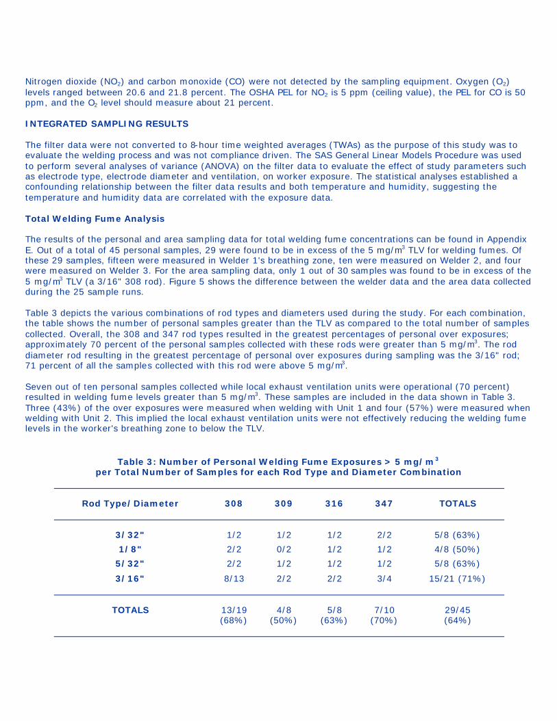
Nitrogen dioxide (NO2) and carbon monoxide (CO) were not detected by the sampling equipment. Oxygen (O2) levels ranged between 20.6 and 21.8 percent. The OSHA PEL for NO2 is 5 ppm (ceiling value), the PEL for CO is 50 ppm, and the O2 level should measure about 21 percent. INTEGRATED SAMPLING RESULTS The filter data were not converted to 8-hour time weighted averages (TWAs) as the purpose of this study was to evaluate the welding process and was not compliance driven. The SAS General Linear Models Procedure was used to perform several analyses of variance (ANOVA) on the filter data to evaluate the effect of study parameters such as electrode type, electrode diameter and ventilation, on worker exposure. The statistical analyses established a confounding relationship between the filter data results and both temperature and humidity, suggesting the temperature and humidity data are correlated with the exposure data. Total Welding Fume Analysis The results of the personal and area sampling data for total welding fume concentrations can be found in Appendix E. Out of a total of 45 personal samples, 29 were found to be in excess of the 5 mg/m3 TLV for welding fumes. Of these 29 samples, fifteen were measured in Welder 1's breathing zone, ten were measured on Welder 2, and four were measured on Welder 3. For the area sampling data, only 1 out of 30 samples was found to be in excess of the 5 mg/m3 TLV (a 3/16" 308 rod). Figure 5 shows the difference between the welder data and the area data collected during the 25 sample runs. Table 3 depicts the various combinations of rod types and diameters used during the study. For each combination, the table shows the number of personal samples greater than the TLV as compared to the total number of samples collected. Overall, the 308 and 347 rod types resulted in the greatest percentages of personal over exposures; approximately 70 percent of the personal samples collected with these rods were greater than 5 mg/m3. The rod diameter rod resulting in the greatest percentage of personal over exposures during sampling was the 3/16" rod; 71 percent of all the samples collected with this rod were above 5 mg/m3. Seven out of ten personal samples collected while local exhaust ventilation units were operational (70 percent) resulted in welding fume levels greater than 5 mg/m3. These samples are included in the data shown in Table 3. Three (43%) of the over exposures were measured when welding with Unit 1 and four (57%) were measured when welding with Unit 2. This implied the local exhaust ventilation units were not effectively reducing the welding fume levels in the worker's breathing zone to below the TLV.
Table 3: Number of Personal Welding Fume Exposures > 5 mg/m3 per Total Number of Samples for each Rod Type and Diameter Combination
Rod Type/Diameter 308 309 316 347 TOTALS
3/32" 1/2 1/2 1/2 2/2 5/8 (63%)
1/8" 2/2 0/2 1/2 1/2 4/8 (50%)
5/32" 2/2 1/2 1/2 1/2 5/8 (63%)
3/16" 8/13 2/2 2/2 3/4 15/21 (71%)
TOTALS 13/19
(68%) 4/8
(50%) 5/8
(63%) 7/10
(70%) 29/45 (64%)
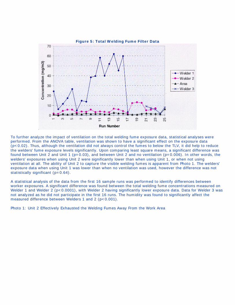
Figure 5: Total Welding Fume Filter Data
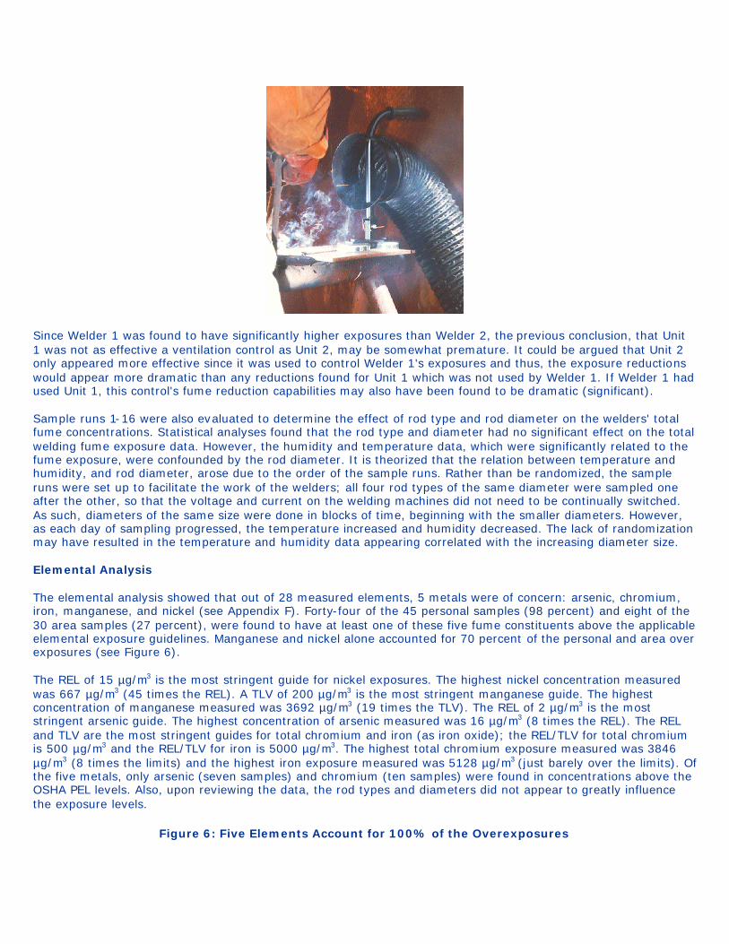
To further analyze the impact of ventilation on the total welding fume exposure data, statistical analyses were performed. From the ANOVA table, ventilation was shown to have a significant effect on the exposure data (p<0.02). Thus, although the ventilation did not always control the fumes to below the TLV, it did help to reduce the welders' fume exposure levels significantly. Upon comparing least square means, a significant difference was found between Unit 2 and Unit 1 (p=0.03), and between Unit 2 and no ventilation (p=0.006). In other words, the welders' exposures when using Unit 2 were significantly lower than when using Unit 1, or when not using ventilation at all. The ability of Unit 2 to capture the visible welding fumes is apparent from Photo 1. The welders' exposure data when using Unit 1 was lower than when no ventilation was used, however the difference was not statistically significant (p=0.64). A statistical analysis of the data from the first 16 sample runs was performed to identify differences between worker exposures. A significant difference was found between the total welding fume concentrations measured on Welder 1 and Welder 2 (p<0.0001), with Welder 2 having significantly lower exposure data. Data for Welder 3 was not analyzed as he did not participate in the first 16 runs. The humidity was found to significantly affect the measured difference between Welders 1 and 2 (p<0.001). Photo 1: Unit 2 Effectively Exhausted the Welding Fumes Away From the Work Area
Since Welder 1 was found to have significantly higher exposures than Welder 2, the previous conclusion, that Unit 1 was not as effective a ventilation control as Unit 2, may be somewhat premature. It could be argued that Unit 2 only appeared more effective since it was used to control Welder 1's exposures and thus, the exposure reductions would appear more dramatic than any reductions found for Unit 1 which was not used by Welder 1. If Welder 1 had used Unit 1, this control's fume reduction capabilities may also have been found to be dramatic (significant). Sample runs 1-16 were also evaluated to determine the effect of rod type and rod diameter on the welders' total fume concentrations. Statistical analyses found that the rod type and diameter had no significant effect on the total welding fume exposure data. However, the humidity and temperature data, which were significantly related to the fume exposure, were confounded by the rod diameter. It is theorized that the relation between temperature and humidity, and rod diameter, arose due to the order of the sample runs. Rather than be randomized, the sample runs were set up to facilitate the work of the welders; all four rod types of the same diameter were sampled one after the other, so that the voltage and current on the welding machines did not need to be continually switched. As such, diameters of the same size were done in blocks of time, beginning with the smaller diameters. However, as each day of sampling progressed, the temperature increased and humidity decreased. The lack of randomization may have resulted in the temperature and humidity data appearing correlated with the increasing diameter size. Elemental Analysis The elemental analysis showed that out of 28 measured elements, 5 metals were of concern: arsenic, chromium, iron, manganese, and nickel (see Appendix F). Forty-four of the 45 personal samples (98 percent) and eight of the 30 area samples (27 percent), were found to have at least one of these five fume constituents above the applicable elemental exposure guidelines. Manganese and nickel alone accounted for 70 percent of the personal and area over exposures (see Figure 6). The REL of 15 µg/m3 is the most stringent guide for nickel exposures. The highest nickel concentration measured was 667 µg/m3 (45 times the REL). A TLV of 200 µg/m3 is the most stringent manganese guide. The highest concentration of manganese measured was 3692 µg/m3 (19 times the TLV). The REL of 2 µg/m3 is the most stringent arsenic guide. The highest concentration of arsenic measured was 16 µg/m3 (8 times the REL). The REL and TLV are the most stringent guides for total chromium and iron (as iron oxide); the REL/TLV for total chromium is 500 µg/m3 and the REL/TLV for iron is 5000 µg/m3. The highest total chromium exposure measured was 3846 µg/m3 (8 times the limits) and the highest iron exposure measured was 5128 µg/m3 (just barely over the limits). Of the five metals, only arsenic (seven samples) and chromium (ten samples) were found in concentrations above the OSHA PEL levels. Also, upon reviewing the data, the rod types and diameters did not appear to greatly influence the exposure levels.
Figure 6: Five Elements Account for 100% of the Overexposures
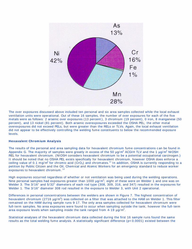
The over exposures discussed above included ten personal and six area samples collected while the local exhaust ventilation units were operational. Out of these 16 samples, the number of over exposures for each of the five metals were as follows: 2 arsenic over exposures (13 percent), 3 chromium (19 percent), 0 iron, 8 manganese (50 percent), and 13 nickel (81 percent). Both arsenic overexposures exceeded the OSHA PEL; the other metal overexposures did not exceed PELs, but were greater than the RELs or TLVs. Again, the local exhaust ventilation did not appear to be effectively controlling the welding fume constituents to below the recommended exposure levels. Hexavalent Chromium Analysis The results of the personal and area sampling data for hexavalent chromium fume concentrations can be found in Appendix G. The majority of samples were greatly in excess of the 50 µg/m3 ACGIH TLV and the 1 µg/m3 NIOSH REL for hexavalent chromium. (NIOSH considers hexavalent chromium to be a potential occupational carcinogen.) It should be noted that no OSHA PEL exists specifically for hexavalent chromium, however OSHA does enforce a ceiling value of 0.1 mg/m3 for chromic acid (CrO3) and chromates.11 In addition, OSHA is currently responding to a petition by Public Citizen and the Oil, Chemical and Atomic Workers for an emergency standard to reduce worker exposures to hexavalent chromium. 12 High exposures occurred regardless of whether or not ventilation was being used during the welding operations. Nine personal samples had exposures greater than 1000 µg/m3; eight of these were on Welder 1 and one was on Welder 3. The 3/16" and 5/32" diameters of each rod type (308, 309, 316, and 347) resulted in the exposures for Welder 1. The 3/16" diameter 308 rod resulted in the exposure to Welder 3, with Unit 2 operational. Differences in personal concentrations between the welders are shown in Figure 7. The highest concentration of hexavalent chromium (2716 µg/m3) was collected on a filter that was attached to the HAM on Welder 1. This filter remained on the HAM during sample runs 9-17. The only area samples collected for hexavalent chromium were full-term samples. No area exposures were found to occur when sampling outside the tank; however the full-term area exposure levels when sampling inside the tank ranged from 4-19 µg/m3. Statistical analyses of the hexavalent chromium data collected during the first 16 sample runs found the same results as the total welding fume analysis. A statistically significant difference (p<0.0001) existed between the

concentrations measured on Welders 1 and 2; this difference was affected by the humidity data (p<0.0001). The type of welding rod and the diameter of the rod, again, had no direct effect on the concentration data.
Figure 7: Hexavalent Chromium Filter Data
Additional statistical analyses were performed to further evaluate the effect of ventilation on the hexavalent chromium fume exposure data. The use of ventilation was shown to have a significant effect on reducing the exposure data (p<0.04), even though all the samples collected with ventilation were still above the TLV. Upon comparing least square means, a significant difference was found to exist between Unit 2 and no ventilation (p=0.02). In other words, the use of Unit 2 significantly reduced the amount of hexavalent chromium fume in the welders' breathing zone when compared to welding with no ventilation. The exposure to hexavalent chromium fume when using Unit 1 was not statistically significantly different from when no ventilation was used (p=0.9). Overall, the hexavalent chromium fume levels were lower when the welders used Unit 2 as compared to Unit 1, however this difference was not proven to be statistically significant (p=0.09). REAL-TIME DATA RESULTS The personal and area average relative concentration data, as measured by the HAM, appeared to be lowest when the ventilation was operational (Figure 8). The highest average area relative concentration occurred when the welding operation was located inside the building with no ventilation (sample run 25). No area data was retrieved for sample run 19. The highest average personal concentrations occurred during sample runs 9, 11, and 14. These three runs all occurred while the HAM was located in the breathing zone of Welder 1. A comparison of the HAM results (Figure 8) and the total welding fume filter data results (Figure 5), shows the two data sets follow similar patterns over the 25 sampling runs. However the relative concentrations as measured by the HAM in terms of mg/m3 were much higher than what was actually measured using the filters.
Figure 8: Total Welding Fume Relative Concentration Data as Collected by the HAM
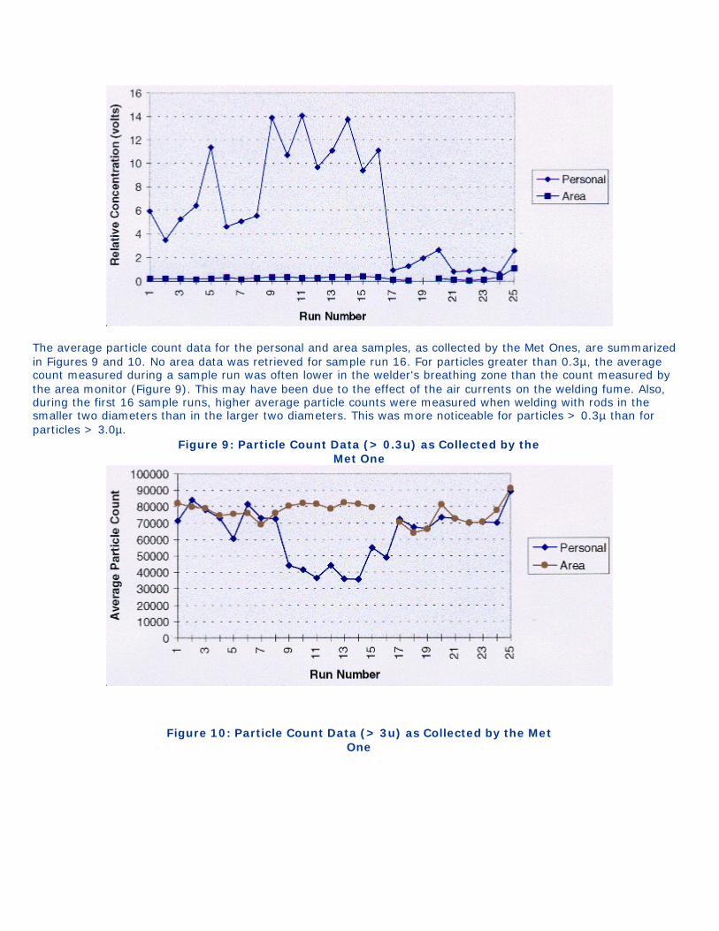
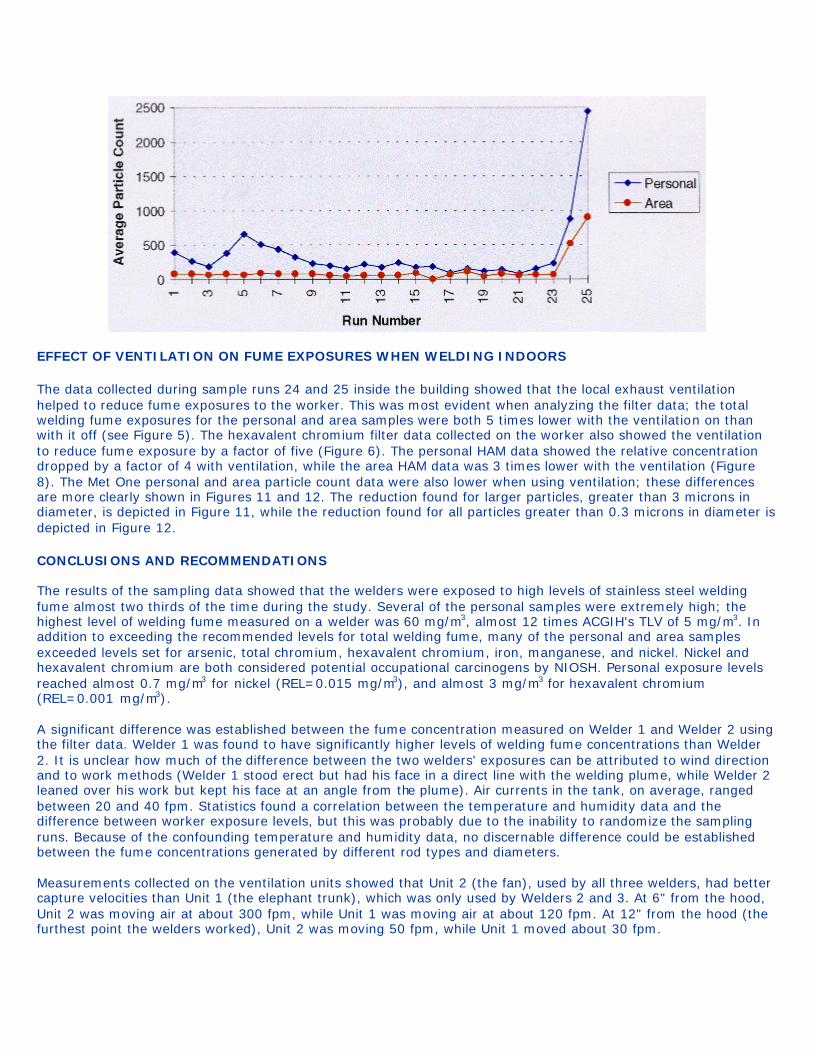
The average particle count data for the personal and area samples, as collected by the Met Ones, are summarized in Figures 9 and 10. No area data was retrieved for sample run 16. For particles greater than 0.3µ, the average count measured during a sample run was often lower in the welder's breathing zone than the count measured by the area monitor (Figure 9). This may have been due to the effect of the air currents on the welding fume. Also, during the first 16 sample runs, higher average particle counts were measured when welding with rods in the smaller two diameters than in the larger two diameters. This was more noticeable for particles > 0.3µ than for particles > 3.0µ.
Figure 9: Particle Count Data (> 0.3u) as Collected by the Met One
Figure 10: Particle Count Data (> 3u) as Collected by the Met One
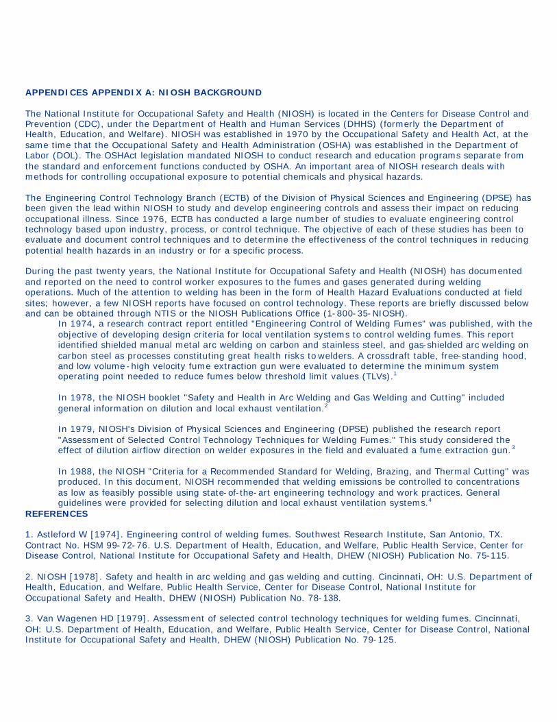
EFFECT OF VENTILATION ON FUME EXPOSURES WHEN WELDING INDOORS The data collected during sample runs 24 and 25 inside the building showed that the local exhaust ventilation helped to reduce fume exposures to the worker. This was most evident when analyzing the filter data; the total welding fume exposures for the personal and area samples were both 5 times lower with the ventilation on than with it off (see Figure 5). The hexavalent chromium filter data collected on the worker also showed the ventilation to reduce fume exposure by a factor of five (Figure 6). The personal HAM data showed the relative concentration dropped by a factor of 4 with ventilation, while the area HAM data was 3 times lower with the ventilation (Figure 8). The Met One personal and area particle count data were also lower when using ventilation; these differences are more clearly shown in Figures 11 and 12. The reduction found for larger particles, greater than 3 microns in diameter, is depicted in Figure 11, while the reduction found for all particles greater than 0.3 microns in diameter is depicted in Figure 12. CONCLUSIONS AND RECOMMENDATIONS The results of the sampling data showed that the welders were exposed to high levels of stainless steel welding fume almost two thirds of the time during the study. Several of the personal samples were extremely high; the highest level of welding fume measured on a welder was 60 mg/m3, almost 12 times ACGIH's TLV of 5 mg/m3. In addition to exceeding the recommended levels for total welding fume, many of the personal and area samples exceeded levels set for arsenic, total chromium, hexavalent chromium, iron, manganese, and nickel. Nickel and hexavalent chromium are both considered potential occupational carcinogens by NIOSH. Personal exposure levels reached almost 0.7 mg/m3 for nickel (REL=0.015 mg/m3), and almost 3 mg/m3 for hexavalent chromium (REL=0.001 mg/m3). A significant difference was established between the fume concentration measured on Welder 1 and Welder 2 using the filter data. Welder 1 was found to have significantly higher levels of welding fume concentrations than Welder 2. It is unclear how much of the difference between the two welders' exposures can be attributed to wind direction and to work methods (Welder 1 stood erect but had his face in a direct line with the welding plume, while Welder 2 leaned over his work but kept his face at an angle from the plume). Air currents in the tank, on average, ranged between 20 and 40 fpm. Statistics found a correlation between the temperature and humidity data and the difference between worker exposure levels, but this was probably due to the inability to randomize the sampling runs. Because of the confounding temperature and humidity data, no discernable difference could be established between the fume concentrations generated by different rod types and diameters. Measurements collected on the ventilation units showed that Unit 2 (the fan), used by all three welders, had better capture velocities than Unit 1 (the elephant trunk), which was only used by Welders 2 and 3. At 6" from the hood, Unit 2 was moving air at about 300 fpm, while Unit 1 was moving air at about 120 fpm. At 12" from the hood (the furthest point the welders worked), Unit 2 was moving 50 fpm, while Unit 1 moved about 30 fpm.
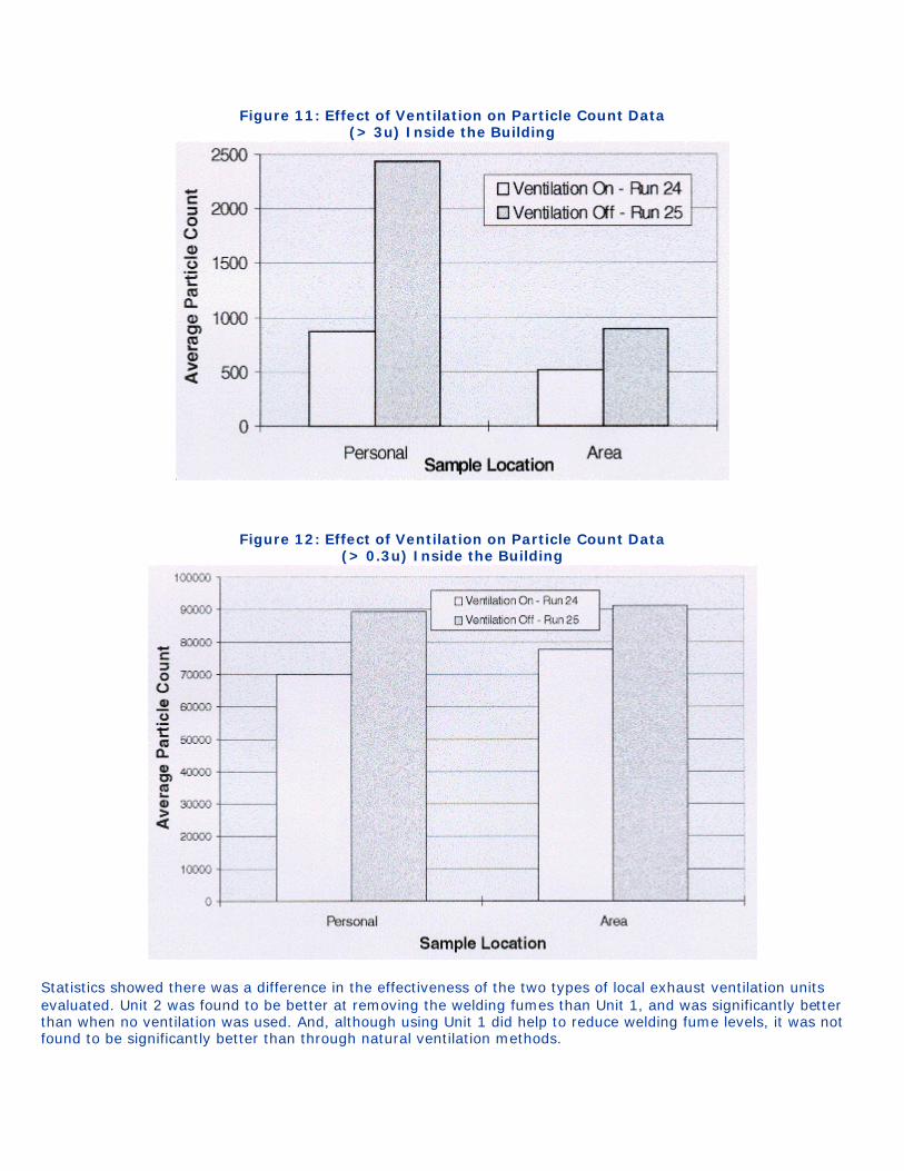
Figure 11: Effect of Ventilation on Particle Count Data (> 3u) Inside the Building
Figure 12: Effect of Ventilation on Particle Count Data (> 0.3u) Inside the Building
Statistics showed there was a difference in the effectiveness of the two types of local exhaust ventilation units evaluated. Unit 2 was found to be better at removing the welding fumes than Unit 1, and was significantly better than when no ventilation was used. And, although using Unit 1 did help to reduce welding fume levels, it was not found to be significantly better than through natural ventilation methods.

In summary, stainless steel welding can result in high fume exposures to workers. When the workers are welding outside, even in a semi-enclosed tank, air currents play a significant role in how much fume is carried into the worker's breathing zone. If the wind is directed towards the welder, his fume exposure is going to increase. Even the use of local exhaust ventilation may not have a significant effect on reducing the worker's exposure. The worker's exposure level is going to be dependent on how strong the wind is and in what direction the wind is moving, where the worker is standing in relation to the welding plume, and where the ventilation is positioned. As such, an adequate reduction in worker exposures by using local exhaust ventilation when welding outside is not guaranteed, even in a semi-enclosed area, due to the potentially strong effects of even a slight wind current. Ventilation will help to reduce fume exposures but the ability of the welder to always stand upwind of the fumes may even be more important when working outside. REFERENCES 1. AWS Safety and Health Committee [1993]. Effects of welding on health VIII. Miami, FL: American Welding Society, Safety and Health Committee; ISBN: 0-87171-437-X. 2. Hewett P [1988]. Summary ranking of small businesses most in need of control technology from 23 OSHA state consultation programs. Memorandum of December 20, 1988, from P. Hewett, Division of Respiratory Disease Studies, to Small Business Initiative Committee, National Institute for Occupational Safety and Health, Centers for Disease Control and Prevention, Public Health Service, U.S. Department of Health and Human Services. 3. Webster HK [1995]. Welding could become an OSHA priority. Welding Journal 2:7. 4. NIOSH [1988]. Criteria for a recommended standard: occupational exposure to welding, brazing, and thermal cutting. Cincinnati, OH: U.S. Department of Health and Human Services, Public Health Service, Centers for Disease Control, National Institute for Occupational Safety and Health, DHHS (NIOSH) Publication No. 88-110. 5. NIOSH [1994]. NIOSH pocket guide to chemical hazards. Cincinnati, OH: U.S. Department of Health and Human Services, Public Health Service, Centers for Disease Control and Prevention, National Institute for Occupational Safety and Health, DHHS (NIOSH) Publication No. 94-116. 6. ACGIH [1994]. Threshold limit values for chemical substances and physical agents and biological exposure indices. Cincinnati, OH: American Conference of Governmental Industrial Hygienists. 7. NIOSH [1984]. Nuisance dust total, Method 0500. In: NIOSH Manual of Analytical Methods, 3rd ed., with supplements 1, 2, 3, and 4. Cincinnati, OH: U.S. Department of Health and Human Services, Public Health Service, Centers for Disease Control, National Institute for Occupational Safety and Health, NIOSH Publication No. 84-100. 8. NIOSH [1992]. Analyzing workplace exposures using direct reading instruments and video exposure monitoring techniques. Cincinnati OH: U.S. Department of Health and Human Services, Public Health Service, Centers for Disease Control and Prevention, National Institute for Occupational Safety and Health DHHS (NIOSH) Publication No. 92-104. 9. Gressel MG, Heitbrink WA, McGlothlin JD, Fischbach TJ [1987]. Advantages of real-time data acquisition for exposure assessment. Appl Ind Hyg 3(11):316-320. 10. ACGIH [1995]. Industrial ventilation, a manual of recommended practices. 22nd ed. Cincinnati, OH: American Conference of Governmental Industrial Hygienists. 11. CFR. Code of Federal regulations [1994]. Occupational Safety and Health Administration: OSHA Table Z-2. 29CFR 1910.1000. Washington, D.C.: U.S. Government Printing Office, Federal Register. 12. Bureau of National Affairs [1996]. BNA Occupational Safety & Health Daily, Article No. 32741404. Washington, D.C. September 30, 1996.
APPENDICES APPENDIX A: NIOSH BACKGROUND The National Institute for Occupational Safety and Health (NIOSH) is located in the Centers for Disease Control and Prevention (CDC), under the Department of Health and Human Services (DHHS) (formerly the Department of Health, Education, and Welfare). NIOSH was established in 1970 by the Occupational Safety and Health Act, at the same time that the Occupational Safety and Health Administration (OSHA) was established in the Department of Labor (DOL). The OSHAct legislation mandated NIOSH to conduct research and education programs separate from the standard and enforcement functions conducted by OSHA. An important area of NIOSH research deals with methods for controlling occupational exposure to potential chemicals and physical hazards. The Engineering Control Technology Branch (ECTB) of the Division of Physical Sciences and Engineering (DPSE) has been given the lead within NIOSH to study and develop engineering controls and assess their impact on reducing occupational illness. Since 1976, ECTB has conducted a large number of studies to evaluate engineering control technology based upon industry, process, or control technique. The objective of each of these studies has been to evaluate and document control techniques and to determine the effectiveness of the control techniques in reducing potential health hazards in an industry or for a specific process. During the past twenty years, the National Institute for Occupational Safety and Health (NIOSH) has documented and reported on the need to control worker exposures to the fumes and gases generated during welding operations. Much of the attention to welding has been in the form of Health Hazard Evaluations conducted at field sites; however, a few NIOSH reports have focused on control technology. These reports are briefly discussed below and can be obtained through NTIS or the NIOSH Publications Office (1-800-35-NIOSH).
In 1974, a research contract report entitled "Engineering Control of Welding Fumes" was published, with the objective of developing design criteria for local ventilation systems to control welding fumes. This report identified shielded manual metal arc welding on carbon and stainless steel, and gas-shielded arc welding on carbon steel as processes constituting great health risks to welders. A crossdraft table, free-standing hood, and low volume-high velocity fume extraction gun were evaluated to determine the minimum system operating point needed to reduce fumes below threshold limit values (TLVs).1 In 1978, the NIOSH booklet "Safety and Health in Arc Welding and Gas Welding and Cutting" included general information on dilution and local exhaust ventilation.2 In 1979, NIOSH's Division of Physical Sciences and Engineering (DPSE) published the research report "Assessment of Selected Control Technology Techniques for Welding Fumes." This study considered the effect of dilution airflow direction on welder exposures in the field and evaluated a fume extraction gun.3 In 1988, the NIOSH "Criteria for a Recommended Standard for Welding, Brazing, and Thermal Cutting" was produced. In this document, NIOSH recommended that welding emissions be controlled to concentrations as low as feasibly possible using state-of-the-art engineering technology and work practices. General guidelines were provided for selecting dilution and local exhaust ventilation systems.4
REFERENCES 1. Astleford W [1974]. Engineering control of welding fumes. Southwest Research Institute, San Antonio, TX. Contract No. HSM 99-72-76. U.S. Department of Health, Education, and Welfare, Public Health Service, Center for Disease Control, National Institute for Occupational Safety and Health, DHEW (NIOSH) Publication No. 75-115. 2. NIOSH [1978]. Safety and health in arc welding and gas welding and cutting. Cincinnati, OH: U.S. Department of Health, Education, and Welfare, Public Health Service, Center for Disease Control, National Institute for Occupational Safety and Health, DHEW (NIOSH) Publication No. 78-138. 3. Van Wagenen HD [1979]. Assessment of selected control technology techniques for welding fumes. Cincinnati, OH: U.S. Department of Health, Education, and Welfare, Public Health Service, Center for Disease Control, National Institute for Occupational Safety and Health, DHEW (NIOSH) Publication No. 79-125.
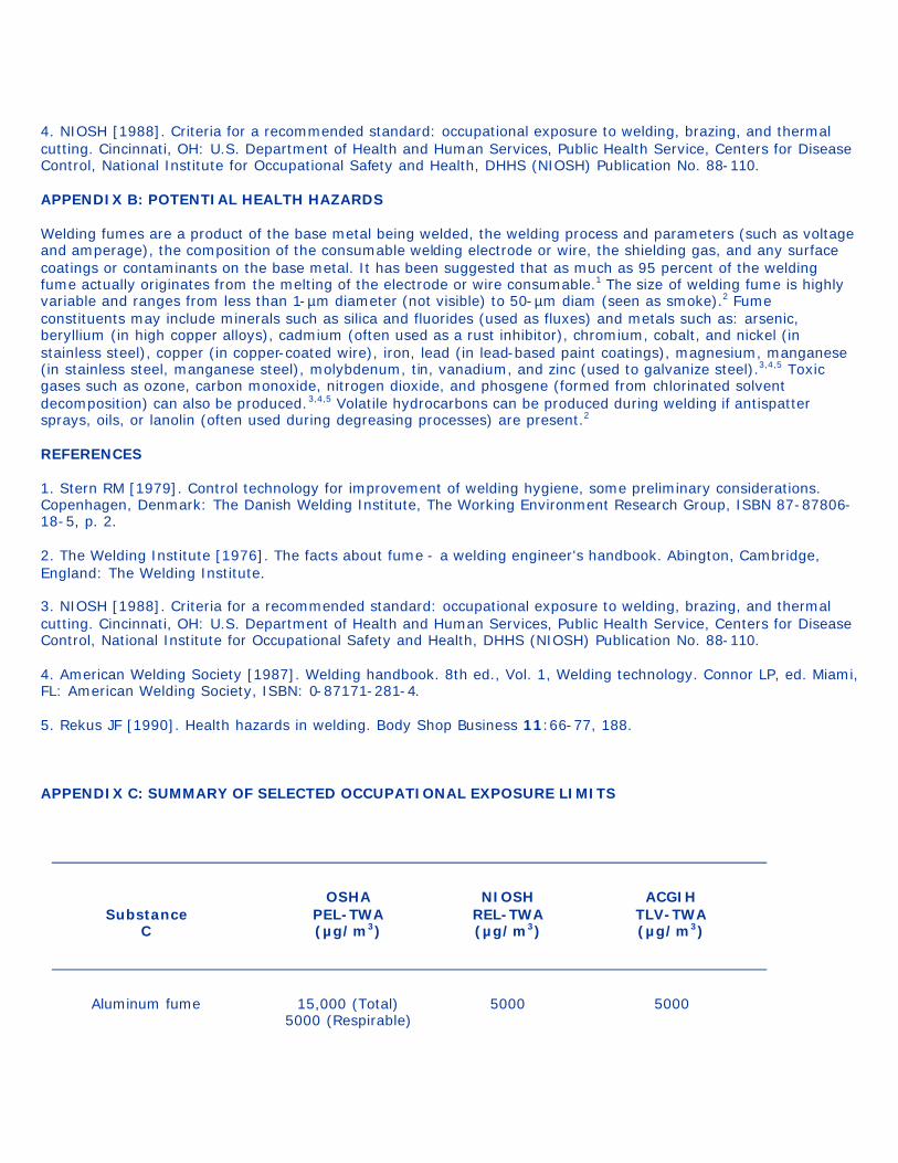
4. NIOSH [1988]. Criteria for a recommended standard: occupational exposure to welding, brazing, and thermal cutting. Cincinnati, OH: U.S. Department of Health and Human Services, Public Health Service, Centers for Disease Control, National Institute for Occupational Safety and Health, DHHS (NIOSH) Publication No. 88-110. APPENDIX B: POTENTIAL HEALTH HAZARDS Welding fumes are a product of the base metal being welded, the welding process and parameters (such as voltage and amperage), the composition of the consumable welding electrode or wire, the shielding gas, and any surface coatings or contaminants on the base metal. It has been suggested that as much as 95 percent of the welding fume actually originates from the melting of the electrode or wire consumable.1 The size of welding fume is highly variable and ranges from less than 1-µm diameter (not visible) to 50-µm diam (seen as smoke).2 Fume constituents may include minerals such as silica and fluorides (used as fluxes) and metals such as: arsenic, beryllium (in high copper alloys), cadmium (often used as a rust inhibitor), chromium, cobalt, and nickel (in stainless steel), copper (in copper-coated wire), iron, lead (in lead-based paint coatings), magnesium, manganese (in stainless steel, manganese steel), molybdenum, tin, vanadium, and zinc (used to galvanize steel).3,4,5 Toxic gases such as ozone, carbon monoxide, nitrogen dioxide, and phosgene (formed from chlorinated solvent decomposition) can also be produced.3,4,5 Volatile hydrocarbons can be produced during welding if antispatter sprays, oils, or lanolin (often used during degreasing processes) are present.2 REFERENCES 1. Stern RM [1979]. Control technology for improvement of welding hygiene, some preliminary considerations. Copenhagen, Denmark: The Danish Welding Institute, The Working Environment Research Group, ISBN 87-87806-18-5, p. 2. 2. The Welding Institute [1976]. The facts about fume - a welding engineer's handbook. Abington, Cambridge, England: The Welding Institute. 3. NIOSH [1988]. Criteria for a recommended standard: occupational exposure to welding, brazing, and thermal cutting. Cincinnati, OH: U.S. Department of Health and Human Services, Public Health Service, Centers for Disease Control, National Institute for Occupational Safety and Health, DHHS (NIOSH) Publication No. 88-110. 4. American Welding Society [1987]. Welding handbook. 8th ed., Vol. 1, Welding technology. Connor LP, ed. Miami, FL: American Welding Society, ISBN: 0-87171-281-4. 5. Rekus JF [1990]. Health hazards in welding. Body Shop Business 11:66-77, 188. APPENDIX C: SUMMARY OF SELECTED OCCUPATIONAL EXPOSURE LIMITS
Substance
C
OSHA PEL-TWA (µg/m3)
NIOSH REL-TWA (µg/m3)
ACGIH TLV-TWA (µg/m3)
Aluminum fume 15,000 (Total) 5000 (Respirable)
5000 5000
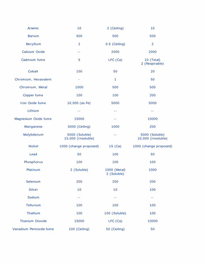
Arsenic 10 2 (Ceiling) 10
Barium 500 500 500
Beryllium 2 0.5 (Ceiling) 2
Calcium Oxide -- 2000 2000
Cadmium fume 5 LFC (Ca) 10 (Total) 2 (Respirable)
Cobalt 100 50 20
Chromium, Hexavalent - 1 50
Chromium, Metal 1000 500 500
Copper fume 100 100 200
Iron Oxide fume 10,000 (as Fe) 5000 5000
Lithium -- -- --
Magnesium Oxide fume 15000 -- 10000
Manganese 5000 (Ceiling) 1000 200
Molybdenum 5000 (Soluble) 15,000 (Insoluble)
-- 5000 (Soluble) 10,000 (Insoluble)
Nickel 1000 (change proposed) 15 (Ca) 1000 (change proposed)
Lead 50 100 50
Phosphorus 100 100 100
Platinum 2 (Soluble) 1000 (Metal) 2 (Soluble)
1000
Selenium 200 200 200
Silver 10 10 100
Sodium -- -- --
Tellurium 100 100 100
Thallium 100 100 (Soluble) 100
Titanium Dioxide 15000 LFC (Ca) 10000
Vanadium Pentoxide fume 100 (Ceiling) 50 (Ceiling) 50

Yttrium 1000 1000 1000
Zinc Oxide fume 5000 5000 5000
Zirconium 5000 5000 5000
Welding fumes - LFC (Ca) 5000
LFC=lowest feasible concentration Ca=NIOSH potential occupational carcinogen
APPENDIX D: ANALYTICAL DETECTION AND QUANTITATION LIMITS
Analyte LOD (µg/filter)
LOQ (µg/filter)
Silver 0.08 0.25
Aluminum 1 3.5
Arsenic* 3, 1, 0.5 7.5, 3.3, 1.7
Barium 0.05 0.17
Beryllium* 0.03, 0.01 0.075, 0.035
Calcium 3 7.5
Cadmium 0.08 0.25
Cobalt 0.2 0.43
Chromium 0.5 1.7
Hexavalent Chromium 0.3 0.9
Copper 0.08 0.25
Iron 0.8 2.5
Lithium* 0.2, 0.03 0.45, 0.38, 0.25
Magnesium 0.5 1.7
Manganese 0.01 0.035
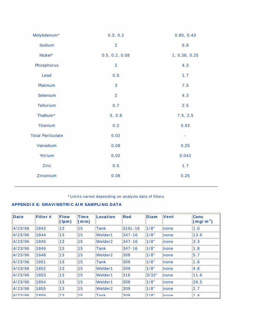
Molybdenum* 0.3, 0.2 0.85, 0.43
Sodium 2 6.8
Nickel* 0.5, 0.2, 0.08 1, 0.38, 0.25
Phosphorus 2 4.3
Lead 0.5 1.7
Platinum 3 7.5
Selenium 2 4.3
Tellurium 0.7 2.5
Thallium* 3, 0.8 7.5, 2.5
Titanium 0.2 0.43
Total Particulate 0.02 -
Vanadium 0.08 0.25
Yttrium 0.02 0.043
Zinc 0.5 1.7
Zirconium 0.08 0.25
*Limits varied depending on analysis date of filters APPENDIX E: GRAVIMETRIC AIR SAMPLING DATA
Date Filter # Flow (lpm)
Time (min)
Location Rod Diam Vent Conc (mg/m3)
4/23/96 1843 13 15 Tank 316L-16 1/8" none 1.0
4/23/96 1844 13 15 Welder1 347-16 1/8" none 13.6
4/23/96 1845 13 15 Welder2 347-16 1/8" none 3.3
4/23/96 1846 13 15 Tank 347-16 1/8" none 1.8
4/23/96 1848 13 15 Welder2 308 1/8" none 5.7
4/23/96 1851 13 15 Tank 309 1/8" none 1.6
4/23/96 1852 13 15 Welder1 309 1/8" none 4.8
4/23/96 1853 13 15 Welder1 316 3/32" none 11.6
4/23/96 1854 13 15 Welder1 308 1/8" none 26.5
4/23/96 1855 13 15 Welder2 309 1/8" none 2.7
4/23/96 1856 13 15 Tank 308 1/8" none 1.4
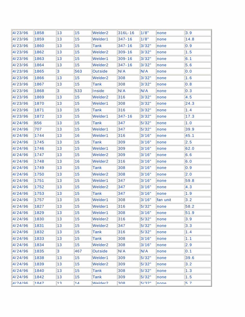
4/23/96 1858 13 15 Welder2 316L-16 1/8" none 3.9
4/23/96 1859 13 15 Welder1 347-16 1/8" none 14.8
4/23/96 1860 13 15 Tank 347-16 3/32" none 0.9
4/23/96 1862 13 15 Welder2 309-16 3/32" none 1.5
4/23/96 1863 13 15 Welder1 309-16 3/32" none 6.1
4/23/96 1864 13 15 Welder2 347-16 3/32" none 5.6
4/23/96 1865 3 563 Outside N/A N/A none 0.0
4/23/96 1866 13 15 Welder2 308 3/32" none 1.6
4/23/96 1867 13 15 Tank 308 3/32" none 0.8
4/23/96 1868 3 533 Inside N/A N/A none 0.3
4/23/96 1869 13 15 Welder2 316 3/32" none 4.5
4/23/96 1870 13 15 Welder1 308 3/32" none 24.3
4/23/96 1871 13 15 Tank 316 3/32" none 1.4
4/23/96 1872 13 15 Welder1 347-16 3/32" none 17.3
4/24/96 656 13 15 Tank 347 5/32" none 1.0
4/24/96 707 13 15 Welder1 347 5/32" none 39.9
4/24/96 1744 13 16 Welder1 316 3/16" none 45.1
4/24/96 1745 13 15 Tank 309 3/16" none 2.5
4/24/96 1746 13 15 Welder1 309 3/16" none 62.0
4/24/96 1747 13 15 Welder2 309 3/16" none 6.6
4/24/96 1748 13 16 Welder2 316 3/16" none 6.0
4/24/96 1749 13 15 Tank 308 3/16" none 0.9
4/24/96 1750 13 15 Welder2 308 3/16" none 2.0
4/24/96 1751 13 15 Welder1 347 3/16" none 59.8
4/24/96 1752 13 15 Welder2 347 3/16" none 4.3
4/24/96 1753 13 15 Tank 347 3/16" none 1.9
4/24/96 1757 13 15 Welder1 308 3/16" fan unit 3.2
4/24/96 1827 13 15 Welder1 316 5/32" none 58.2
4/24/96 1829 13 15 Welder1 308 3/16" none 51.9
4/24/96 1830 13 15 Welder2 316 5/32" none 3.9
4/24/96 1831 13 15 Welder2 347 5/32" none 3.3
4/24/96 1832 13 15 Tank 316 5/32" none 1.4
4/24/96 1833 13 15 Tank 308 3/16" none 1.1
4/24/96 1834 13 15 Welder2 308 3/16" none 2.9
4/24/96 1835 3 467 Outside N/A N/A none 0.1
4/24/96 1838 13 15 Welder1 309 5/32" none 39.6
4/24/96 1839 13 15 Welder2 309 5/32" none 3.2
4/24/96 1840 13 15 Tank 308 5/32" none 1.3
4/24/96 1842 13 15 Tank 309 5/32" none 1.5
4/24/96 1847 13 14 Welder2 308 5/32" none 5.7
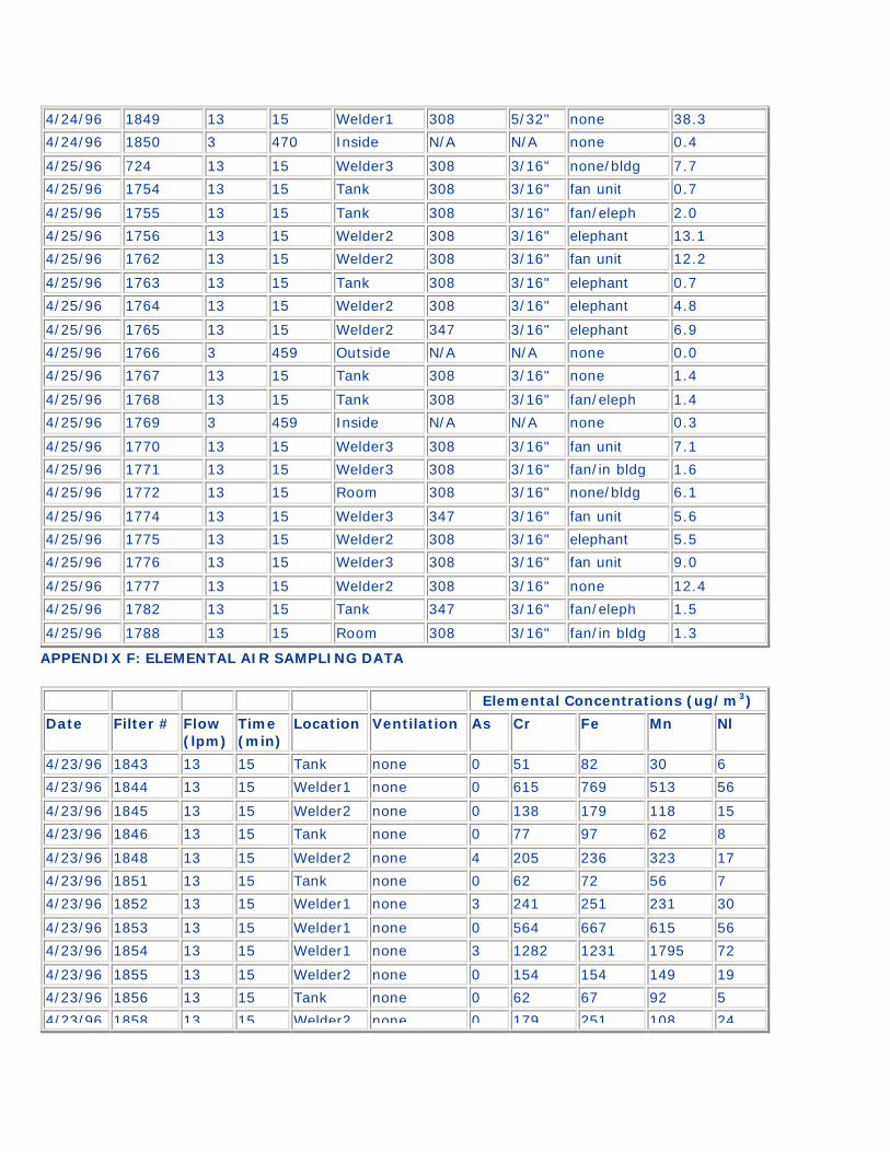
4/24/96 1849 13 15 Welder1 308 5/32" none 38.3
4/24/96 1850 3 470 Inside N/A N/A none 0.4
4/25/96 724 13 15 Welder3 308 3/16" none/bldg 7.7
4/25/96 1754 13 15 Tank 308 3/16" fan unit 0.7
4/25/96 1755 13 15 Tank 308 3/16" fan/eleph 2.0
4/25/96 1756 13 15 Welder2 308 3/16" elephant 13.1
4/25/96 1762 13 15 Welder2 308 3/16" fan unit 12.2
4/25/96 1763 13 15 Tank 308 3/16" elephant 0.7
4/25/96 1764 13 15 Welder2 308 3/16" elephant 4.8
4/25/96 1765 13 15 Welder2 347 3/16" elephant 6.9
4/25/96 1766 3 459 Outside N/A N/A none 0.0
4/25/96 1767 13 15 Tank 308 3/16" none 1.4
4/25/96 1768 13 15 Tank 308 3/16" fan/eleph 1.4
4/25/96 1769 3 459 Inside N/A N/A none 0.3
4/25/96 1770 13 15 Welder3 308 3/16" fan unit 7.1
4/25/96 1771 13 15 Welder3 308 3/16" fan/in bldg 1.6
4/25/96 1772 13 15 Room 308 3/16" none/bldg 6.1
4/25/96 1774 13 15 Welder3 347 3/16" fan unit 5.6
4/25/96 1775 13 15 Welder2 308 3/16" elephant 5.5
4/25/96 1776 13 15 Welder3 308 3/16" fan unit 9.0
4/25/96 1777 13 15 Welder2 308 3/16" none 12.4
4/25/96 1782 13 15 Tank 347 3/16" fan/eleph 1.5
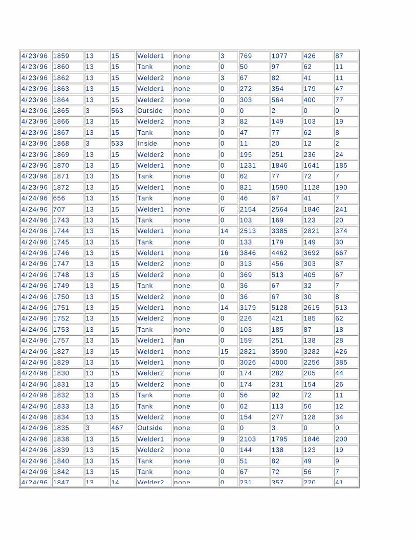
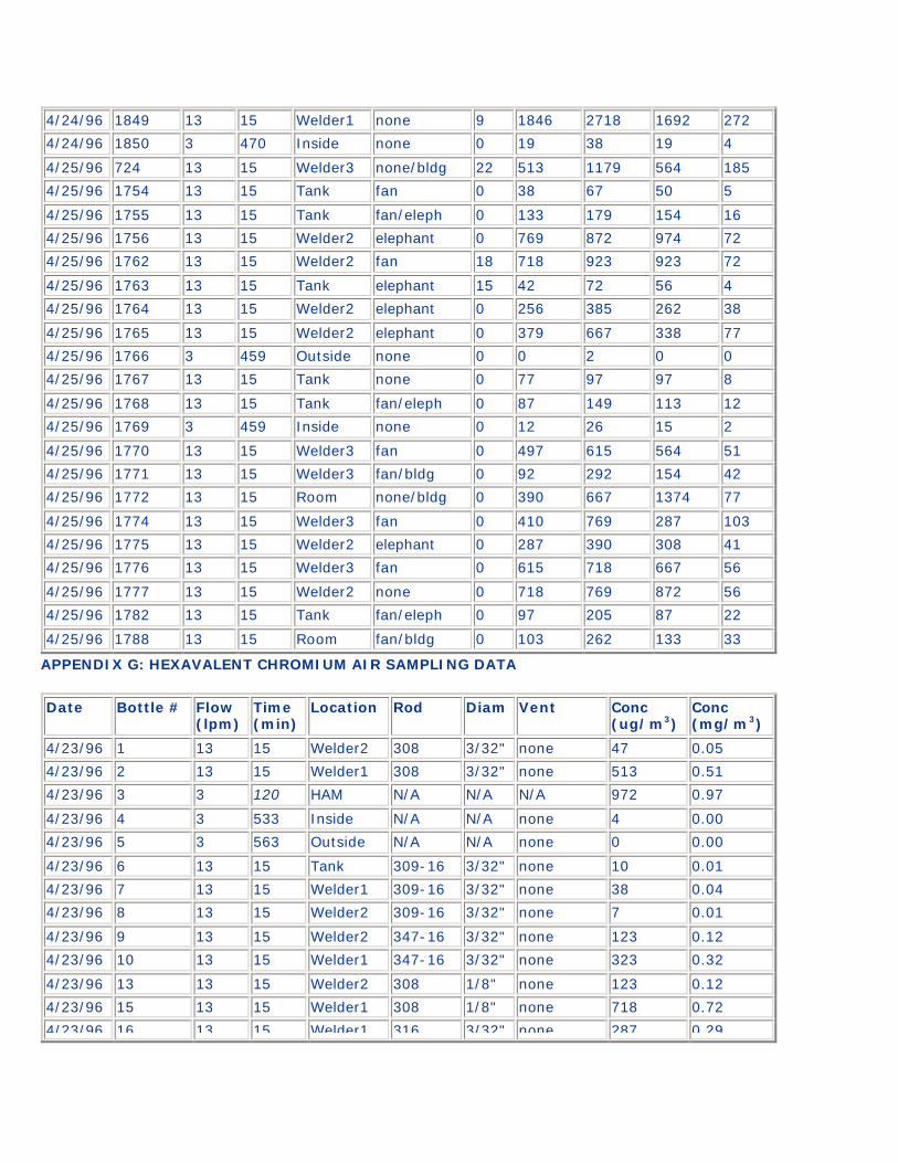
4/25/96 1788 13 15 Room 308 3/16" fan/in bldg 1.3 APPENDIX F: ELEMENTAL AIR SAMPLING DATA
Elemental Concentrations (ug/m3)
Date Filter # Flow (lpm)
Time (min)
Location Ventilation As Cr Fe Mn Nl
4/23/96 1843 13 15 Tank none 0 51 82 30 6
4/23/96 1844 13 15 Welder1 none 0 615 769 513 56
4/23/96 1845 13 15 Welder2 none 0 138 179 118 15
4/23/96 1846 13 15 Tank none 0 77 97 62 8
4/23/96 1848 13 15 Welder2 none 4 205 236 323 17
4/23/96 1851 13 15 Tank none 0 62 72 56 7
4/23/96 1852 13 15 Welder1 none 3 241 251 231 30
4/23/96 1853 13 15 Welder1 none 0 564 667 615 56
4/23/96 1854 13 15 Welder1 none 3 1282 1231 1795 72
4/23/96 1855 13 15 Welder2 none 0 154 154 149 19
4/23/96 1856 13 15 Tank none 0 62 67 92 5
4/23/96 1858 13 15 Welder2 none 0 179 251 108 24
4/23/96 1859 13 15 Welder1 none 3 769 1077 426 87
4/23/96 1860 13 15 Tank none 0 50 97 62 11
4/23/96 1862 13 15 Welder2 none 3 67 82 41 11
4/23/96 1863 13 15 Welder1 none 0 272 354 179 47
4/23/96 1864 13 15 Welder2 none 0 303 564 400 77
4/23/96 1865 3 563 Outside none 0 0 2 0 0
4/23/96 1866 13 15 Welder2 none 3 82 149 103 19
4/23/96 1867 13 15 Tank none 0 47 77 62 8
4/23/96 1868 3 533 Inside none 0 11 20 12 2
4/23/96 1869 13 15 Welder2 none 0 195 251 236 24
4/23/96 1870 13 15 Welder1 none 0 1231 1846 1641 185
4/23/96 1871 13 15 Tank none 0 62 77 72 7
4/23/96 1872 13 15 Welder1 none 0 821 1590 1128 190
4/24/96 656 13 15 Tank none 0 46 67 41 7
4/24/96 707 13 15 Welder1 none 6 2154 2564 1846 241
4/24/96 1743 13 15 Tank none 0 103 169 123 20
4/24/96 1744 13 15 Welder1 none 14 2513 3385 2821 374
4/24/96 1745 13 15 Tank none 0 133 179 149 30
4/24/96 1746 13 15 Welder1 none 16 3846 4462 3692 667
4/24/96 1747 13 15 Welder2 none 0 313 456 303 87
4/24/96 1748 13 15 Welder2 none 0 369 513 405 67
4/24/96 1749 13 15 Tank none 0 36 67 32 7
4/24/96 1750 13 15 Welder2 none 0 36 67 30 8
4/24/96 1751 13 15 Welder1 none 14 3179 5128 2615 513
4/24/96 1752 13 15 Welder2 none 0 226 421 185 62
4/24/96 1753 13 15 Tank none 0 103 185 87 18
4/24/96 1757 13 15 Welder1 fan 0 159 251 138 28
4/24/96 1827 13 15 Welder1 none 15 2821 3590 3282 426
4/24/96 1829 13 15 Welder1 none 0 3026 4000 2256 385
4/24/96 1830 13 15 Welder2 none 0 174 282 205 44
4/24/96 1831 13 15 Welder2 none 0 174 231 154 26
4/24/96 1832 13 15 Tank none 0 56 92 72 11
4/24/96 1833 13 15 Tank none 0 62 113 56 12
4/24/96 1834 13 15 Welder2 none 0 154 277 128 34
4/24/96 1835 3 467 Outside none 0 0 3 0 0
4/24/96 1838 13 15 Welder1 none 9 2103 1795 1846 200
4/24/96 1839 13 15 Welder2 none 0 144 138 123 19
4/24/96 1840 13 15 Tank none 0 51 82 49 9
4/24/96 1842 13 15 Tank none 0 67 72 56 7
4/24/96 1847 13 14 Welder2 none 0 231 357 220 41
4/24/96 1849 13 15 Welder1 none 9 1846 2718 1692 272
4/24/96 1850 3 470 Inside none 0 19 38 19 4
4/25/96 724 13 15 Welder3 none/bldg 22 513 1179 564 185
4/25/96 1754 13 15 Tank fan 0 38 67 50 5
4/25/96 1755 13 15 Tank fan/eleph 0 133 179 154 16
4/25/96 1756 13 15 Welder2 elephant 0 769 872 974 72
4/25/96 1762 13 15 Welder2 fan 18 718 923 923 72
4/25/96 1763 13 15 Tank elephant 15 42 72 56 4
4/25/96 1764 13 15 Welder2 elephant 0 256 385 262 38
4/25/96 1765 13 15 Welder2 elephant 0 379 667 338 77
4/25/96 1766 3 459 Outside none 0 0 2 0 0
4/25/96 1767 13 15 Tank none 0 77 97 97 8
4/25/96 1768 13 15 Tank fan/eleph 0 87 149 113 12
4/25/96 1769 3 459 Inside none 0 12 26 15 2
4/25/96 1770 13 15 Welder3 fan 0 497 615 564 51
4/25/96 1771 13 15 Welder3 fan/bldg 0 92 292 154 42
4/25/96 1772 13 15 Room none/bldg 0 390 667 1374 77
4/25/96 1774 13 15 Welder3 fan 0 410 769 287 103
4/25/96 1775 13 15 Welder2 elephant 0 287 390 308 41
4/25/96 1776 13 15 Welder3 fan 0 615 718 667 56
4/25/96 1777 13 15 Welder2 none 0 718 769 872 56
4/25/96 1782 13 15 Tank fan/eleph 0 97 205 87 22
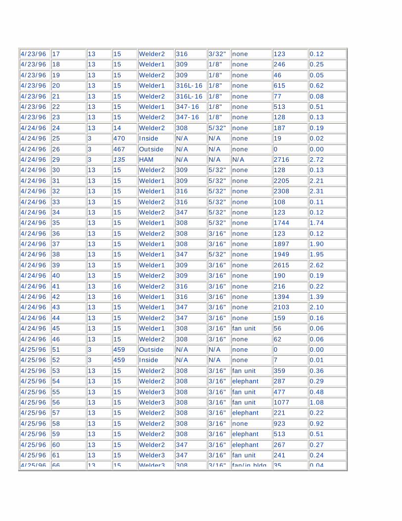
4/25/96 1788 13 15 Room fan/bldg 0 103 262 133 33 APPENDIX G: HEXAVALENT CHROMIUM AIR SAMPLING DATA
Date Bottle # Flow (lpm)
Time (min)
Location Rod Diam Vent Conc (ug/m3)
Conc (mg/m3)
4/23/96 1 13 15 Welder2 308 3/32" none 47 0.05
4/23/96 2 13 15 Welder1 308 3/32" none 513 0.51
4/23/96 3 3 120 HAM N/A N/A N/A 972 0.97
4/23/96 4 3 533 Inside N/A N/A none 4 0.00
4/23/96 5 3 563 Outside N/A N/A none 0 0.00
4/23/96 6 13 15 Tank 309-16 3/32" none 10 0.01
4/23/96 7 13 15 Welder1 309-16 3/32" none 38 0.04
4/23/96 8 13 15 Welder2 309-16 3/32" none 7 0.01
4/23/96 9 13 15 Welder2 347-16 3/32" none 123 0.12
4/23/96 10 13 15 Welder1 347-16 3/32" none 323 0.32
4/23/96 13 13 15 Welder2 308 1/8" none 123 0.12
4/23/96 15 13 15 Welder1 308 1/8" none 718 0.72
4/23/96 16 13 15 Welder1 316 3/32" none 287 0.29
4/23/96 17 13 15 Welder2 316 3/32" none 123 0.12
4/23/96 18 13 15 Welder1 309 1/8" none 246 0.25
4/23/96 19 13 15 Welder2 309 1/8" none 46 0.05
4/23/96 20 13 15 Welder1 316L-16 1/8" none 615 0.62
4/23/96 21 13 15 Welder2 316L-16 1/8" none 77 0.08
4/23/96 22 13 15 Welder1 347-16 1/8" none 513 0.51
4/23/96 23 13 15 Welder2 347-16 1/8" none 128 0.13
4/24/96 24 13 14 Welder2 308 5/32" none 187 0.19
4/24/96 25 3 470 Inside N/A N/A none 19 0.02
4/24/96 26 3 467 Outside N/A N/A none 0 0.00
4/24/96 29 3 135 HAM N/A N/A N/A 2716 2.72
4/24/96 30 13 15 Welder2 309 5/32" none 128 0.13
4/24/96 31 13 15 Welder1 309 5/32" none 2205 2.21
4/24/96 32 13 15 Welder1 316 5/32" none 2308 2.31
4/24/96 33 13 15 Welder2 316 5/32" none 108 0.11
4/24/96 34 13 15 Welder2 347 5/32" none 123 0.12
4/24/96 35 13 15 Welder1 308 5/32" none 1744 1.74
4/24/96 36 13 15 Welder2 308 3/16" none 123 0.12
4/24/96 37 13 15 Welder1 308 3/16" none 1897 1.90
4/24/96 38 13 15 Welder1 347 5/32" none 1949 1.95
4/24/96 39 13 15 Welder1 309 3/16" none 2615 2.62
4/24/96 40 13 15 Welder2 309 3/16" none 190 0.19
4/24/96 41 13 16 Welder2 316 3/16" none 216 0.22
4/24/96 42 13 16 Welder1 316 3/16" none 1394 1.39
4/24/96 43 13 15 Welder1 347 3/16" none 2103 2.10
4/24/96 44 13 15 Welder2 347 3/16" none 159 0.16
4/24/96 45 13 15 Welder1 308 3/16" fan unit 56 0.06
4/24/96 46 13 15 Welder2 308 3/16" none 62 0.06
4/25/96 51 3 459 Outside N/A N/A none 0 0.00
4/25/96 52 3 459 Inside N/A N/A none 7 0.01
4/25/96 53 13 15 Welder2 308 3/16" fan unit 359 0.36
4/25/96 54 13 15 Welder2 308 3/16" elephant 287 0.29
4/25/96 55 13 15 Welder3 308 3/16" fan unit 477 0.48
4/25/96 56 13 15 Welder3 308 3/16" fan unit 1077 1.08
4/25/96 57 13 15 Welder2 308 3/16" elephant 221 0.22
4/25/96 58 13 15 Welder2 308 3/16" none 923 0.92
4/25/96 59 13 15 Welder2 308 3/16" elephant 513 0.51
4/25/96 60 13 15 Welder2 347 3/16" elephant 267 0.27
4/25/96 61 13 15 Welder3 347 3/16" fan unit 241 0.24
4/25/96 66 13 15 Welder3 308 3/16" fan/in bldg 35 0.04

4/25/96 67 13 15 Welder3 308 3/16" none/bldg 236 0.24
4/25/96 77 3 120 HAM N/A N/A N/A 306 0.31