advances.in.fingerprint.technology.second.edition.ebook-eenindex-of.co.uk/tutorials-2/advances in...
TRANSCRIPT


S E C O N D E D I T I O NS E C O N D E D I T I O N
Advances inFingerprint Technology
Advances inFingerprint Technology

CRC SERIES IN FORENSIC AND POLICE SCIENCE
BARRY A. J. FISHER, Series EditorL.A. County Sheriff’s Department
TECHNIQUES OF CRIME SCENE INVESTIGATIONSixth Edition
Barry A. J. Fisher
SCIENTIFIC EXAMINATION OF QUESTIONED DOCUMENTSRevised EditionOrdway Hilton
ADVANCES IN FINGERPRINT TECHNOLOGYSecond Edition
Henry C. LeeR. E. Gaensslen
INSTRUMENTAL DATA FOR DRUG ANALYSISSecond Edition, Volumes 1–4
Terry Mills, IIIJ. Conrad Roberson
INSTRUMENTAL DATA FOR DRUG ANALYSISSecond Edition, Volume 5
Terry Mills, IIIJ. Conrad RobersonH. Horton McCurdy
William H. Wall
INSTRUMENTAL DATA FOR DRUG ANALYSISSecond Edition, Volumes 6-7
Terry Mills, IIIJ. Conrad Roberson
William H. WallKevin L. Lothridge
William D. McDougallMichael W. Gilbert

Boca Raton London New York Washington, D.C.CRC Press
E D I T E D B Y
S E C O N D E D I T I O NS E C O N D E D I T I O N
Henry C. Lee and R. E. Gaensslen
Advances inFingerprint Technology
Advances inFingerprint Technology

This book contains information obtained from authentic and highly regarded sources. Reprinted materialis quoted with permission, and sources are indicated. A wide variety of references are listed. Reasonableefforts have been made to publish reliable data and information, but the author and the publisher cannotassume responsibility for the validity of all materials or for the consequences of their use.
Neither this book nor any part may be reproduced or transmitted in any form or by any means, electronicor mechanical, including photocopying, microfilming, and recording, or by any information storage orretrieval system, without prior permission in writing from the publisher.
All rights reserved. Authorization to photocopy items for internal or personal use, or the personal or internaluse of specific clients, may be granted by CRC Press LLC, provided that $1.50 per page photocopied is paiddirectly to Copyright Clearance Center, 222 Rosewood Drive, Danvers, MA 01923 USA. The fee code forusers of the Transactional Reporting Service is ISBN 0-8493-0923-9/01/$0.00+$1.50. The fee is subject tochange without notice. For organizations that have been granted a photocopy license by the CCC, aseparate system of payment has been arranged.
The consent of CRC Press LLC does not extend to copying for general distribution, for promotion, forcreating new works, or for resale. Specific permission must be obtained in writing from CRC Press LLCfor such copying.
Direct all inquiries to CRC Press LLC, 2000 N.W. Corporate Blvd., Boca Raton, Florida 33431.
Trademark Notice:
Product or corporate names may be trademarks or registered trademarks, and areused only for identification and explanation, without intent to infringe.
Visit the CRC Press Web site at www.crcpress.com
© 2001 by CRC Press LLC
No claim to original U.S. Government worksInternational Standard Book Number 0-8493-0923-9
Library of Congress Card Number 2001025816Printed in the United States of America 1 2 3 4 5 6 7 8 9 0
Printed on acid-free paper
Library of Congress Cataloging-in-Publication Data
Advances in fingerprint technology / edited by Henry C. Lee, R.E. Gaensslen.--2nd ed.p. cm -- (CRC series in forensic and police science)
Includes bibliographical references and index.ISBN 0-8493-0923-9 (alk. paper)1. Fingerprints. 2. Fingerprints--Data processing. I. Lee, Henry C. II. Gaensslen, R. E.
(Robert E.) III. Series.
HV6074 .A43 2001363.25'8--dc21
2001025816
0923 FmFrame Page iv Wednesday, May 16, 2001 12:10 PM

Preface
The first edition of this book was published as a volume in the Elsevier Seriesin Forensic and Police Science. Elsevier’s book business has since beenacquired by CRC Press LLC and CRC has supported and extended theirforensic science program. We thank CRC for the opportunity to revise
Advances in Fingerprint Technology
to this second edition.Fingerprints is an area in which there have been many new and exciting
developments in the past two decades or so, although advances in DNAtyping have tended to dominate both the forensic science literature andpopular information about advances in forensic sciences. Particularly in therealm of methods for developing latent prints, but also in the growth ofimaging and AFIS technologies, fingerprint science has seen extraordinarybreakthroughs because creative applications of principles derived from phys-ics and organic chemistry have been applied to it.
Fingerprints constitute one of the most important categories of physicalevidence. They are among the few that can be truly individualized. Fingerprintindividuality is widely accepted by scientists and the courts alike. Lately therehave been some modest challenges to whether a firm scientific basis existsfor fingerprint individuality, based on the U.S. Supreme Court’s 1993
Daubertv. Merrell Dow Pharmaceuticals, Inc.
decision [113 S.Ct. 2786 (1993)] in whichnew standards for the admissibility of scientific evidence were articulated forthe first time. The issues underlying these challenges are treated in Chapters 9and 10. A perspective on the history and development of fingerprinting andthe fundamentals of latent print identification are treated in Chapters 1 and2, revised from the first edition. Latent fingerprint residue chemistry, onwhich every latent print detection technique is ultimately based, is coveredin detail in a new Chapter 3. Chapter 4, the survey of latent print develop-ment methods and techniques, has been revised and updated. Chapter 5 onninydrin analogues has been revised and updated. New chapters on physicaldevelopers (Chapter 7) and photoluminescent nanoparticles (Chapter 6) areadded. AFIS system technology and fingerprint imaging are now widespreadand may be considered mature. They are covered in a new Chapter 8.
0923 FmFrame Page v Wednesday, May 16, 2001 12:10 PM

The first edition of this volume was dedicated to the memory and lifetimework of Robert D. Olsen, Sr., who wrote the original Chapter 2, but passedaway unexpectedly before the book could be published. That chapter hasbeen revised and retained in this edition.
We want to thank all the contributors to this revised edition for theiroutstanding work and cooperation in bringing this work to completion. Wealso thank the staff at CRC, especially our acquisitions editor, Becky McEldowney, for making the task comparatively painless. Again we thank ourwives, Margaret and Jacqueline, for their continued love and patience withus and our work habits.
0923 FmFrame Page vi Saturday, May 19, 2001 2:20 PM

Acknowledgments
We gratefully acknowledge the assistance of Ms. Nancy Folk, Ms. ChengSheaw-Guey, Mr. Hsieh Sung-shan, and Mr. Kenneth Zercie in the prepara-tion of the original Chapter 3 of the first edition. We particularly thank Ms.Erin Gould, a M.S. graduate of the University of Illinois at Chicago forensicscience program, for her significant help with revised Chapter 4 for thispresent edition. We also thank Robert Ramotowski of the U.S. Secret ServiceForensic Services Division for helpful commentary on and additional infor-mation for the revised Chapter 4.
0923 FmFrame Page vii Wednesday, May 16, 2001 12:10 PM

Contributors
Joseph Almog, Ph.D.
Casali Institute of Applied ChemistryHebrew University of JerusalemJerusalem, [email protected]
John Berry, FFS, BEM
Fingerprint Examiner and Historian (Retired)
South Hatfield, Hertfordshire, England
Antonio Cantu, Ph.D.
Forensic Services DivisionU.S. Secret ServiceWashington, [email protected]
R. E. Gaensslen, Ph.D.
Forensic Science, College of PharmacyUniversity of Illinois at ChicagoChicago, [email protected]
Robert J. Hazen
Spotsylvania, Virginia
Anil K. Jain, Ph.D.
Department of Computer Science and Engineering
Michigan State UniversityEast Lansing, [email protected]
James L. Johnson
Forensic Services DivisionU.S. Secret ServiceWashington, D.C.
Henry C. Lee, Ph.D.
Connecticut State Police Forensic Science Laboratory
Meriden, Connecticut
E. Roland Menzel, Ph.D.
Center for Forensic StudiesTexas Tech UniversityLubbock, [email protected]
Sharath Pankanti
IBM T. J. Watson Research CenterHawthorne, New [email protected]
Clarence E. Phillips
Robert Ramotowski
Forensic Services DivisionU.S. Secret ServiceWashington, [email protected]
David A. Stoney, Ph.D.
McCrone Research InstituteChicago, Illinois
and Clinical Professor Forensic ScienceUniversity of Illinois at ChicagoChicago, [email protected]
0923 FmFrame Page ix Wednesday, May 16, 2001 12:10 PM

Table of Contents
PrefaceAcknowledgmentsThe EditorsContributors
1
History and Development of Fingerprinting
John Berry and David A. Stoney
2
Identification of Latent Prints
Robert D. Olsen, Sr. and Henry C. Lee
3
Composition of Latent Print Residue
Robert S. Ramotowski
4
Methods of Latent Fingerprint Development
Henry C. Lee and R. E. Gaensslen
5
Fingerprint Development by Ninhydrin and Its Analogues
Joseph Almog
6
Fingerprint Detection with Photoluminescent Nanoparticles
E. Roland Menzel
0923 FmFrame Page xi Wednesday, May 16, 2001 12:10 PM

7
Silver Physical Development of Latent Prints
Antonio Cantu and James L. Johnson
8
Automated Fingerprint Identification and Imaging Systems
Anil Jain and Sharath Pankanti
9
Measurement of Fingerprint Individuality
David A. Stoney
10
The Expert Fingerprint Witness
Robert J. Hazen and Clarence E. Phillips
0923 FmFrame Page xii Wednesday, May 16, 2001 12:10 PM

History and Development of Fingerprinting
JOHN BERRY
DAVID A. STONEY*
Contents
IntroductionEvolution and the Elliptical Whorl (1976)Neolithic Bricks (7000 B.C.)Prehistoric Carvings (3000 B.C.)MummiesFinger Imprints on Artifacts in Antiquity (circa 3000 B.C.)Grauballe Man (A.D. 400)Philosophical Transactions (1684)De Externo Tactus Organo (1686)William of Orange (1690)Thomas Bewick (1753–1828)Concerning the External Physiological Examination of the Integumentary System (1823)Fingerprint Classification
Dr. Ivan Vucetich (1858–1925)The Henry SystemSir Edward Henry and Sir William HerschelDr. Henry Faulds (1843–1930)Sir Francis Galton (1822–1911)
Early Fingerprint Usage in Other CountriesGermanyCubaCanadaAustralia and New ZealandUnited States of America
Developments to DateReferenceAddendum to the First EditionUpdate
1
0923Ch01Frame Page 1 Monday, May 14, 2001 1:34 PM

Introduction
The fascinating story of the development and use of fingerprints in the lasthundred years will only be properly appreciated if the reader is acquaintedwith some knowledge of dactyloscopy; therefore I will briefly outline thebasic details of this science. The inside surfaces of the hands from fingertipsto wrist and the bottom surfaces of the feet from the tip of the big toe to therear of the heel contain minute ridges of skin, with furrows between eachridge. A cross section of a finger would look exactly like the cross section ofa plowed field. Whereas on a plowed field the ridges and furrows run instraight parallel lines, on the hands and feet the ridges and furrows frequentlycurve and, especially on the fingertips and toe ends, the ridges and furrowsform complicated patterns. The ridges have pores along their entire lengththat exude perspiration; hence, when an article is picked up, the perspirationruns along the ridges and leaves an exact impression of the ridges, just as aninked rubber stamp leaves its impression on a blank sheet of paper.
Ridges and furrows have evolved on the hands and feet to fulfill threespecific functions:
1. Exudation of perspiration2. Tactile facility3. Provision of a gripping surface
The ridges and furrows form seven basic characteristics, as shown inFigure 1.1. Some authorities consider that only two types of characteristics
Figure 1.1
Ridge characteristics. (Drawn by John Berry.)
0923Ch01Frame Page 2 Monday, May 14, 2001 1:34 PM

are present, a ridge ending and a bifurcation, all other characteristics beingvariations of the two basic forms. I consider that my illustration defines themost important varieties of ridge detail, also known as ridge characteristics.
The ridges and furrows form patterns on the last joint of the fingers andtoes, forming four basic types, as shown in Figure 1.2. There are variationsof these patterns, especially with whorls, but these are the province of thefingerprint expert. Every person in the world shares these patterns — aperson can have all of one type or even a mixture of all of them. The everydayuse of fingers as an identification method and the production of finger andpalm evidence in courts of law are based on one magnificent premise: noone has ever been found who has a sequence of ridge detail on the handsand feet that is identical to the ridge detail of any other person.
Evolution and the Elliptical Whorl (1976)
Before I researched the history of fingerprints in 1975, the earliest evidenceof ridge detail on the hands and feet of humans was seen in the 4000-year-old mummies of ancient Egypt. The hands and feet of mummies have beenexamined on numerous occasions, and I can confirm the presence of ridgedetail on the mummies’ digits. Before 1975, the only other evidence reportedwas the presence of a small portion of palm imprint on hardened mud foundin Egypt on a paleolithic site at the Sebekian deposit, Kom Ombo plain, onthe east bank of the river Nile, dated around 10,000 years ago. The fact thatprimates have ridge detail was announced for the first time, as far as I candiscover, by Joannes Evangelista Purkinje in his thesis (discussed later) pub-lished on December 22, 1823. He wrote:
In the hands of the monkeys, as well as in their prehensile tails, similar linesoccur, the distinction of which adds to the knowledge of the characteristics
Figure 1.2
Basic fingerprint patterns.
0923Ch01Frame Page 3 Monday, May 14, 2001 1:34 PM

of all species. Zoologists, unless they consider them unimportant, will addfurther details.
Purkinje illustrated a palm impression and a small portion of the prehensiletail of a spider monkey.
In 1975–1976, I and my colleagues in the Fingerprint Office in Hertford-shire, U.K. — Roger Ball, David Brooker, Nicholas Hall, Stephen Haylock,and Martin Leadbetter — commenced protracted research to confirm thatall species of primates have ridge detail on their hands and feet in patternsand toe ends that conform to human patterns (see Figure 1.2). We prepareda list of over 180 species of primates from the tree shrews (family Tupaiidae)to the gorilla (family Pongidae) and prepared a roster whereby, in smallgroups, we visited zoos and private collections, examining and in many casestaking impressions of the hands and feet of primates. This research engen-dered publicity in the press and television; one sarcastic writer commentedin a national newspaper that Stephen Haylock was fingerprinting monks.
Eventually, Leadbetter and I contacted Professor and Mrs. Napier, whohave now retired to a Scottish island. Professor Napier was a professionalwriter and a world-renowned expert on the hand; his wife Prue was also awriter and worked in the British Natural History Museum on Cromwell Road,London. We discovered that her terms of reference covered a section of themuseum denied to ordinary visitors where thousands of deceased primates,many of them stuffed with straw, were placed in wide receptacles in an air-conditioned hall. Mrs. Napier explained that a “rule” existed whereby whena primate died in England, the skin was sent to the museum. This “rule” hasbeen in existence for many years. For example, Roger Ball and I used afingerprint-lifting technique to obtain the entire length of ridge detail fromthe prehensile tail of a red howler monkey that had died in 1829. Figure 1.3shows an enlarged section of the lift.
The museum authorities gave permission for Roger Ball, Stephen Hay-lock, Martin Leadbetter, and me to examine all the stuffed primates in thehuge collection. Working in pairs and using our vacation days, we eventuallyexamined the hand and foot surfaces of all the primates. In a few instanceswe lifted ridge details from the hands and feet of selected specimens. Thiswas done by carefully smoothing several layers of acrylic paint over thesurfaces and waiting for each layer to dry before peeling it off. When wereturned to the Fingerprint Office in Hertfordshire, the acrylic lifts weredusted with aluminum powder and then lifted with transparent tape andplaced on transparent Cobex, forming a negative duly processed in theCamtac machine, producing a positive impression, i.e., ridges were black andfurrows and pores were white. After 18 months of research, we had become
0923Ch01Frame Page 4 Monday, May 14, 2001 1:34 PM

the first researchers, as far as I can ascertain, to examine and record the hands,feet, and prehensile tails of every species of primate.
In a later section, I shall discuss the fingerprint pioneer Dr. Henry Faulds(pronounced “folds”) in some detail; but in the present context I believe itis enormously interesting to report that on February 15, 1880, Faulds wroteto evolutionist Charles Darwin requesting his aid in obtaining the fingerimpressions of lemurs, anthropoids, etc. “with a view to throw light onhuman ancestry.” On April 7, 1880, Darwin replied to Faulds:
Dear Sir,The subject to which you refer in your letter of February 15th seems to
me a curious one, which may turn out interesting, but I am sorry to saythat I am most unfortunately situated for offering you any assistance. I livein the country, and from weak health seldom see anyone. I will, however,forward your letter to Mr. F. Galton, who is the man most likely that I canthink of to take up the subject and make further enquiries.
Wishing you success,I remain, dear Sir,Yours faithfully,Charles Darwin
Figure 1.3
Portion of the prehensile tail of a red howler monkey (1829).
0923Ch01Frame Page 5 Monday, May 14, 2001 1:34 PM

The “Mr. F. Galton” referred to in the letter from Darwin in due coursebecame an authority on fingerprint matters in England and was part of anestablishment clique that sought to revile Faulds (to be described later).However, note the amazing chain of events: … fingerprint pioneer Faulds …primates’ fingerprints … Charles Darwin … Mr. F. Galton (later Sir FrancisGalton) … fingerprint pioneer!
During the summer of 1976, I was, as always, fully occupied in my workas a fingerprint expert in Hertfordshire, specializing in searching for theownership of finger imprints found at crime scenes, known in the U.S. bythe particularly apt expression “cold searching.” Many identifications aremade as the direct result of suspects being named by investigating policeofficers, but it is thrilling for a fingerprint expert, even a grizzled veteran likemyself working with fingerprints for 37 years, to delve into the unknown andgive the police a named person for the crime they are investigating, a namecompletely fresh and unknown to them, which we refer to as being “out ofthe blue.” Some astute detectives, when given the name as the result of asuccessful search, attempt to give the impression that somehow “they had anidea” that the name supplied to them was at that time under serious review.Fingerprint experts do not like this because the identification might havebeen made after laboriously searching perhaps thousands of fingerprintforms.
So in 1976 my position was that I had been scanning hundreds, possiblythousands, of fingerprints every working day for almost 22 years and at theback of my mind was the ever-present thought that all primates have “humantype” finger impressions — after all, we are all primates — and, promptedby the letter from Faulds to Darwin, some original thoughts occurred to me.
I had recently read Prue Napier’s book
Monkeys and Apes,
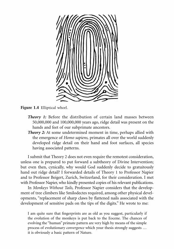
wherein sheillustrated every primate, describing the physical similarities and differencesthat occur in geographically separate areas, such as South America (onlySouth American primates have ridge detail on their prehensile tail strip),Japan, Africa, Sumatra, Gibraltar, India, and Madagascar. I perused bookson plate tectonics, averaging the estimated dates of the separation of Mada-gascar from the East African coast, and calculated that this occurred50,000,000 years ago. Madagascan primates, I mused, differ physically fromAfrican primates, but they also bore ridge detail on their hands and feet. Onefingerprint pattern that frequently occurs on primates in all geographicalareas is the elliptical whorl (Figure 1.4), which is also found on human fingerimpressions. I must stress that arches, tents, loops, and whorls (see Figure 1.2)are also found on primates, but I “latched onto” the elliptical whorl as thebasis for my sudden inspiration. Surely, if East African and Madagascanprimates have elliptical whorls (among other patterns), only two theoriescould account for this phenomenon:
0923Ch01Frame Page 6 Monday, May 14, 2001 1:34 PM
Theory 1:
Before the distribution of certain land masses between50,000,000 and 100,000,000 years ago, ridge detail was present on thehands and feet of our subprimate ancestors.
Theory 2:
At some undetermined moment in time, perhaps allied withthe emergence of
Homo sapiens,
primates all over the world suddenlydeveloped ridge detail on their hand and foot surfaces, all specieshaving associated patterns.
I submit that Theory 2 does not even require the remotest consideration,unless one is prepared to put forward a subtheory of Divine Intervention;but even then, cynically, why would God suddenly decide to gratuitouslyhand out ridge detail? I forwarded details of Theory 1 to Professor Napierand to Professor Beigert, Zurich, Switzerland, for their consideration. I metwith Professor Napier, who kindly presented copies of his relevant publications.
In
Monkeys Without Tails,
Professor Napier considers that the develop-ment of tree climbers like Smilodectes required, among other physical devel-opments, “replacement of sharp claws by flattened nails associated with thedevelopment of sensitive pads on the tips of the digits.” He wrote to me:
I am quite sure that fingerprints are as old as you suggest, particularly ifthe evolution of the monkeys is put back to the Eocene. The chances ofevolving the “human” primate pattern are very high by means of the simpleprocess of evolutionary
convergence
which your thesis strongly suggests …it is obviously a basic pattern of Nature.
Figure 1.4
Elliptical whorl.
0923Ch01Frame Page 7 Monday, May 14, 2001 1:34 PM

For many years Professor Beigert has published numerous books con-cerning ridge detail on the hand and foot surfaces of selected primates. Healso forwarded to me copies of his literature and wrote, making the followingobservations:
I agree with you that dermatoglyphics on palma and planta of primateshave to be dated very early. In my opinion in the Paleocene, 50,000,000–60,000,000 years ago.
In his book
The Evaluation of the Skull, Hands and Feet for PrimateTaxonomy
(1963), Professor Beigert writes:
Much less attention has been given to the fact that among the other senseorgans, the touch receptors underwent a significantly higher development.
My thesis was published in
Fingerprint Whorld
(July 1976) and in myesoteric annual publication
Ridge Detail in Nature
(1979); both publicationswere circulated to fingerprint bureaus, universities, and museums all overthe world. No one has claimed prior publication of my theory regarding thefact that subprimates bore ridge detail before the separation of land masses.
I therefore submit that ridge detail appeared on the hands and feet ofour subprimate ancestors over 100,000,000 years ago (a new 1987 estimatefor the separation of Madagascar from Africa is closer to 200,000,000 years)and that our subprimate ancestors developed ridge detail on their hands andfeet to facilitate the evolutionary requirement for grip, tactile facility, and theexudation of perspiration.
Neolithic Bricks (7000 B.C.)
Dame Kathleen Kenyon carried out excavations in the ancient city of Jericho,and in her book
Archaeology of the Holy Land,
referring to houses datedbetween 7000 B.C. and 6000 B.C., she reported
The bricks of which the walls were constructed were made by hand (not inmoulds, as is usual later), in shape rather like a flattened cigar, with thesurface impressed with a herringbone pattern by pairs of prints of the brick-layer’s thumbs, thus giving a keying such as is provided by the hollow inmodern bricks.
In
Paphos — History and Archaeology
by F. G. Maier and V. Karageorghis,dealing with excavations in Paphos, birthplace of Aphrodite, reference ismade to the walls of the ancient city, eighth century B.C.
0923Ch01Frame Page 8 Monday, May 14, 2001 1:34 PM

The bricks, carefully laid and accurately jointed, are of near uniform sizeand of dark brown clay. A distinctive bright red-clay mortar was used. Manybricks have impressed fingerprints on their lower side.
Prehistoric Carvings (3000 B.C.)
Recently I discovered details on two archaeological items that proved to myentire satisfaction that early humans were cognizant of patterns on theirfingertips. However, before discussing them, I wish to report on the work of“a distinguished fingerprint authority,” a certain Mr. Stockis, who publisheda treatise in the early 1920s in which he attempted to justify his claims thatpersons who carved patterns on standing stones in dolmen on Goat Island,Brittany, France, were aware of ridge detail on their digits. The carvings heillustrated depicted symbolic arches, tents, loops, and whorls.
The so-called Stockis theory was investigated by the eminent fingerprintexpert Professor Harold Cummins, from the U.S., who reported
If it be true that Neolithic men really noted fingerprint patterns, and withthe attention to minute detail which is claimed, credit is due to them for aspontaneous interest and keenness in such observation hardly matched bythe average man of the present day.
In his critique of the Stockis theory, Professor Cummins acknowledges thatpottery making could have revealed ridge detail to Neolithic humans andaccepts that the carvings are “highly suggestive” of fingerprints; he evenconcedes that this could have been associated with hand worship. However,he concludes that although ridge detail can be noted in the carvings, thereare other features included that definitely do not refer to dermatoglyphics.He concluded that “sound evidence that the carved designs had their originin fingerprints appears to be wanting.”
The first of my discoveries concerns a national monument at NewGrange, Republic of Ireland (Eire), that I wrote about in the 1984 edition of
Ridge Detail in Nature
:
The national monument at New Grange dates from around 3,000 B.C. andfeatures a huge man-made mound with a narrow passage leading to aninner burial chamber. An opening is located above the entrance so that forjust a few moments at dawn on 21st December each year the rays of therising sun penetrate along the passage to illuminate the burial chamber. Apostage stamp issued on 4th May 1983 depicts patterns at the monumentincised in stone. I note that the four basic fingerprint patterns are shown,together with numerous deltas. Is it mere coincidence that these patterns
0923Ch01Frame Page 9 Monday, May 14, 2001 1:34 PM

are found on the design, or was the interest of a pre-Celtic artist kindledby a perusal of his fingerprint patterns?
In
Ridge Detail in Nature
(1986) I illustrated and described for the first timein a ridge detail context a carving on a standing stone on Goat Island(Figure 1.5). I wrote:
Megalithic tombs and architectural monuments were built in WesternEurope around 4,000 years ago, and the richest carvings are found in Brit-tany, north western France. It is thought that inspiration for the remarkablydecorated tombs came from Spain and Southern France. A dozen charac-teristic symbols on the tombs represented important items in the lives of
Figure 1.5
Standing stone, Goat Island. (Redrawn by John Berry, from
The Mega-lithic Builders of Western Europe
, Glyn Daniel, 1963.)
0923Ch01Frame Page 10 Monday, May 14, 2001 1:34 PM

the megalithic builders, including axeheads, horns, yokes, the sun, etc. Thisphotograph of carvings from Gavrinnis is covered with symbolic represen-tations, and the seemingly superimposed shape at the bottom of the carvingshows a tent pattern. Ridge detail is scarce, but pores are quite clear on theridges, being especially noticeable on the ridges draped over the centralspine. I have no doubt that this particular carver was aware of patterns onfinger tips, possibly superimposing one of his own patterns, as clear andprecise as any of English wood-carver Thomas Bewick’s fingerprint repre-sentations. (Bewick is discussed later.)
I do accept there is the slight possibility that the New Grange designscould be coincidental, although I do believe that the artist was conversantwith patterns plainly visible on the ends of his fingers or the fingers of hisassociates; but I certainly do not have any doubts whatsoever that the personwho carved the tent pattern (see Figure 1.5) was aware of fingerprint patterns.This megalithic monument, carved in France at about the same time as thepyramids were being built, convinces me that the artisan knew of this pattern,and possibly, to accord individuality to one of his designs, he incorporatedone of his digit patterns, perhaps carved from a mud impression purposelymade. The tent pattern is “squared-off” at the base. The sweat pores arepronounced, equally spaced on the ridges; I regard this as being a mostsignificant pointer. This carving of a tent pattern was not a coincidence: itwas carved from direct observation. I unhesitatingly align myself with, andfully support, the Stockis theory.
Mummies
As I have stated, the examination and recording of ridge detail on the handsand feet of mummies has been reported. I have visited museums in severalcountries, always specifically seeking out the Egyptian sections, and althoughmany of the mummies were wrapped, I have been able to scrutinize ridgedetail on the hands and feet of embalmed bodies on display and confirm thepresence of fingerprint patterns similar to those shown in Figure 1.2.
In 1977, the mummy Asru, from the Temple of Karnak, was fingerprintedby experts in Manchester under the direction of Detective Chief InspectorThomas Fletcher, head of the Fingerprint Bureau of the Greater ManchesterPolice. He kindly sent me a report and illustrations that were subsequentlypublished in Fingerprint Whorld. Mr. Fletcher utilized the technique I have
already described when the Hertfordshire personnel fingerprinted primates:the application of layers of acrylic paint on the digits. (This technique wasinvented by Roger Ball and was revealed for the first time in Fingerprint
Whorld, January 1976.) Mr. Fletcher used his experience as a detective to
0923Ch01Frame Page 11 Monday, May 14, 2001 1:34 PM

discover the occupation of Asru in the Temple of Karnak; she was either adancer or a chantress:
Three thousand years ago Egyptian temple dancers performed their ritualdances barefoot, the foot being used as part of the body’s expression. Thesole was in constant contact with the ground and even on the smoothest offlooring there would be friction and consequent wearing of the ridges onthe underside of the toes and balls of the feet. Asru’s feet did not show anytraces of this constant contact with the floor, the depth of the furrows andthe clarity of the characteristics were not consistent with her having beena dancer, and the alternative of her being a chantress was much moreacceptable.
Finger Imprints on Artifacts in Antiquity (circa 3000 B.C.)
In
Fingerprint Whorld,
October 1976, I published my research on this subjectunder the rather facetious title “Potter Throws Light on Prints.” I considerthat I covered the subject quite fully and wrote:
Research into finger imprints in antiquity is a fascinating subject, becausereferences occur of fingerprints on pottery and figurines in many parts ofthe world, even in pre-history. The scope for detailed research by the fin-gerprint expert is considerable, because my initial source material (quotedlater) reveals authorities finding fingerprints on Neolithic vases, Bronze Agecooking pots, Assyrian clay tablets, ancient Mexican pottery and Aztec clayfigures. Obviously, many of these instances occurred in the manufacture ofarticles where the manipulation of the basic clay into utensils indirectly leftfingerprints. I write here detailing examples which suggest that the finger-prints were purposely indented into the clay. The earliest trace of fingerimprints being purposely impressed occurred in Mesopotamia and datesfrom circa 3,000 B.C. where an authority asserts that a “digital impression”was placed on each brick used in the construction of the king’s storehouse.This method of making identifying marks is also found on bricks used inthe construction of the “royal buildings” in Ancient Egypt. It is pertinentto note that in these two examples the buildings were for kings or pharaohs,suggesting the importance placed in the craftsmanship which was confirmedby the finger impressions of the masons.
William Frederick Bade, once director of the Palestine Institute ofArchaeology, conducted excavations at various sites in Palestine and at oneplace found finger imprints on many pieces of broken pottery. The chaoticstate of this scene caused initial difficulty in dating artifacts, but it transpiredthat a study of the imprints on the numerous shards indicated that one potter
0923Ch01Frame Page 12 Monday, May 14, 2001 1:34 PM

made most of them. These “identifications” permitted the confused debristo be dated accurately; in fact, this particular excavation was dated to thefourth century A.D.
Commenting on this case,
Fingerprint Magazine
(1937)stated that “these impressions were obviously intentional, and, no doubt,represented the workman’s individual trade mark.”
A Chinese clay seal, dated before the third century B.C., has been thefocus of considerable research and speculation for many years. A left thumbimprint is deeply embedded in the seal, and on the reverse side is ancientChinese script representing the name of the person who made the thumbimprint. The mark is so specific in pressure and placing that there can be nodoubt that it was meant as an identifying mark. If this is so, there is the stronginference that the Chinese were aware of the individuality of fingerprints wellover 5000 years ago.
According to Mr. Laufer, a famous researcher who worked at the FieldMuseum of Natural History in the U.S., before the first century B.C., clayseals were used extensively in sealing documents such as official letters andpackages. Of the superb left thumb imprint mentioned above, he stated:
It is out of the question that this imprint is due to a mere accident causedby the handling of the clay piece. This impression is deep and sunk into thesurface of the clay seal and beyond any doubt was effected with intentionalenergy and determination. In reasoning the case out logically, there is noother significance possible than that the thumb print belongs to the ownerof the seal who has made his name on the reverse side. This case is thereforesomewhat analogous to the modern practice of affixing on title deeds thethumb print to the signature, the one being verified by the other. Thisunique specimen is the oldest document so far on record relating to thehistory of the fingerprint system.
There is no evidence to conclude that the ancient Chinese were aware ofthe individuality of fingerprints on a universal basis. However, the care takento impress the clay seals suggests that the persons utilizing this form ofsignature (even should they only be symbolic tokens, as suggested) wereaware that the design on their fingers or thumbs so applied constitutedindividuality. This must represent, even at its crudest level, the local recog-nition that the person who impressed a digit on a seal was permanentlybound to the contents of the documents so certified.
A researcher who dedicated many years of work in this direction,although he was not a fingerprint expert, stated:
Fingerprint identification in our usage of the term appears to have beenpracticed in a simple form in times long past … but the history of fingerprintidentification becomes shadowy as it is traced backwards.
0923Ch01Frame Page 13 Monday, May 14, 2001 1:34 PM

I have examined Roman pottery and noted that finger imprints aresometimes present; one example in my possession shows three whorl types(twin loops) on the semismoothed underside. Yet when I was in Romania in1985, I visited the ruins of a Greek settlement at Hystria, on the western coastof the Black Sea, and found shards of pottery completely devoid of fingerimprints. I was extremely pleased to find the handle and part of the side ofa Getic earthenware vessel among the rubble on the site. It was made duringthe first century B.C., and under examination with my fingerprint magnifyingglass, I could see that the handle and side had been smoothed with fingersso finely that I believe every endeavor had been made to avoid leaving fingerimprints on the finished product. I visited museums in Hystria, Constantsa,and Bucharest, especially looking for finger imprints on pottery, and did noteven find a lone example. Ergo, it is reasonable to assume that the potters inthis area at least decided it was worthwhile removing offending imprints,
which they had noted,
in order to obtain an unsullied surface, a rather civilizedartistic appreciation of subtlety of form.
Grauballe Man (A.D. 400)
On Saturday, April 26, 1952, a body was discovered in the Nebelgard Fennear Grauballe, in Jutland, and
14
C dating revealed that the body had beenin the bog between A.D. 1 and A.D. 400. The skin had been tanned like leatherowing to the preservative qualities of the bog water. The cause of death wasa deep incision across the throat, and it was presumed that the man had beenritually sacrificed to a fertility god to ensure the survival of his fellows. Twomembers of the staff of the police laboratory at Aarhus were entrusted withthe examination of the Grauballe man’s hands and feet. They found the ridgedetail was excellent and were able to take impressions from the body. Theright thumb was “a double curve whorl,” a twin loop, and the right forefingerwas an ulnar loop.
Philosophical Transactions (1684)
The first person to study and describe ridges, furrows, and pores on the handand foot surfaces was English plant morphologist Nehemiah Grew(Figure 1.6), born in Warwickshire in 1641. He was the first fingerprintpioneer; besides writing on the subject, he also published extremely accuratedrawings of finger patterns and areas of the palm. In the 1684 publicationhe described, in the most beautiful phraseology, descriptions and functionsof ridge detail:
0923Ch01Frame Page 14 Monday, May 14, 2001 1:34 PM

For if any one will but take the pains, with an indifferent Glass, to surveythe Palm of his Hand very well washed with a Ball; he may perceive (besidesthose great Lines to which some men have given Names, and those of middlesize call’d the Grain of the skin) innumerable little Ridges, of equal bignessand distance, and everywhere running parallel with one another. And espe-cially, upon the ends and first Joynts of the Fingers and Thumb, upon thetop of the Ball, and near the root of the Thumb a little above the Wrist. Inall which places they are regularly disposed into Spherical Triangles, andEllipticks. Upon these Ridges and Pores, all in Even Rows, and of thatmagnitude, as to be visible to a very good Eye without a Glass. But beingviewed with one, every pore looks like a little Fountain, and the sweat maybe seen to stand therein, as clear as rock water, and as often as it is wipedoff, to spring up within them again. That which Nature intends in theposition of these Ridges is, That they may the better suit with the use andmotion of the Hand: those of the lower side of every Triangle, to the bendingin or clutching of the Fingers: and those of the other two sides, and one ofthe Ellipticks to the pressure of the Hand or Fingers ends against any body,requiring them to yield to the right and left. Upon these Ridges, the Poresare very providently placed, and not in the furrows which lie between them;that so their structure might be more sturdy, and less liable to be depravedby compression; whereby only the Furrows are dilated or contracted, theRidges constantly maintaining themselves and so the Pores unaltered. Andfor the same reason, the Pores are also very large, that they may be still
Figure 1.6
Nehemiah Grew. (Drawn by John Berry.)
0923Ch01Frame Page 15 Monday, May 14, 2001 1:34 PM

better preserved, tho the skin be never so much compressed and condens’d bythe constant use and labour of the Hand. And so those of the Feet, notwith-standing the compression of the skin by the weight of the whole body.
Grew died suddenly on March 25, 1712. He is buried at
Cheshunt ParishChurch, Hertfordshire.
De Externo Tactus Organo (1686)
Grew’s contemporary, Marcello Malpighi (1628–1694), also a plant morphol-ogist, researched the functions of the human skin, and the “Malpighianlayers” were named for him. He worked at the University of Bologna, Italy,and in his publication he mainly dealt with the skin, although he did brieflymention ridge detail. It is believed that Grew and Malpighi corresponded toa degree, but the differences in language were a frustration, strangely becauseGrew was more adept at Latin usage than the Italian.
William of Orange (1690)
I am sure that the reader will think this section is a hoax, but I report herewithone well-known historical fingerprint landmark, and the latest tremendous1987 discovery, both having a direct connection with the expatriate Dutchmonarch William of Orange. The city of Londonderry (now in NorthernIreland) was under siege until relieved by forces under the command ofWilliam of Orange, and in 1691, 225 citizens of Londonderry, who hadsuffered damage and loss during the siege, made a representation to Londonfor compensation. The claimants appended digit impressions on the docu-ment, adjacent to their signatures, obviously considering the individuality oftheir fingers as being inviolable. I have examined a photograph of the doc-ument (and have tried really hard but unsuccessfully to trace the original)and report that the imprints are unfortunately of poor quality, but it mustbe remembered that they were made 300 years ago.
An accidental fire occurred at the historic building Hampton Court, westof London, causing considerable damage; early in 1987, workmen removedsome warped wooden panels in The Little Oak Room, Fountain Court, andfound that the plaster underneath bore 17 complete handprints. I immedi-ately visited the site with Martin Leadbetter and Nicholas Hall, a Hertford-shire Constabulary photographer, and we made a detailed examination,including measurements, photography, and an abortive attempt at lifting.
0923Ch01Frame Page 16 Monday, May 14, 2001 1:34 PM

Most of the handprints were excellent, revealing clear ridge detail; photographA2 (Figure 1.7) shows the finest example. The plaster was made of lime, sand,and animal hairs. Archaeologists told us that The Little Oak Room had beenredecorated in 1689–1690 for King William III and his queen. The hands hadbeen impressed in the plaster before it had hardened. We found that threedifferent people had made the imprints. I do not believe that the plasterers
Figure 1.7
Right palm imprint in plaster, Hampton Court, London, 1689–1690.(Figure supplied by Nicholas John Hall, M.F.S., Hertfordshire.)
0923Ch01Frame Page 17 Monday, May 14, 2001 1:34 PM

would desecrate their handiwork; perchance the vagrant handprints weremade by carpenters, soldiers, or servants who would be aware that large woodenpanels of oak would speedily be placed atop the plaster. It was a fascinatingexperience to have the opportunity to examine the handprints on the wall, albeitthe results of our examination were officially handed to the Hampton Courtauthorities as part of the records of the archaeological and other finds beforerefurbishment; also, our work was featured in an official Home Office film thatis scheduled for television broadcast and publication in book form.
Thomas Bewick (1753–1828)
Thomas Bewick (Figure 1.8) is mentioned quite frequently in fingerprintpublications simply because in a few books he used an engraving of hisfingerprints as a signature. The importance of this fact is that he did this almost200 years ago, and authorities such as Sir William Herschel have credited Bewickwith stimulating their initial interest in the study of fingerprints.
He was born in Ovingham, Northumberland, England, on August 12,1753, the son of a farmer. His early school career was marred by his absencefrom classes and disinterest in Latin, English grammar, and arithmetic,although he was eventually constrained to study them to a reasonable stan-dard, as one contemporary writer put it:
Figure 1.8
Thomas Bewick. (Drawn by John Berry.)
0923Ch01Frame Page 18 Monday, May 14, 2001 1:34 PM

By kindly words of persuasion a reformation was at length affected thatsevere discipline and punishment had failed to accomplish.
He used all the spaces in his school papers to draw murals, and when he usedthese up he continued his artistic progress by chalking designs on gravestonesand the church porch. He became famous in the rural community as anartist, and he decorated the walls of their cottages “with an abundance of myrude productions at a very cheap rate.”
While still a child, his head was scalded and thereafter his crown had nohair, necessitating, when he grew older, the application of a brown silk cap.When he was 14 years old, he became an apprentice to an engraver inNewcastle, and after 5 years he completed his apprenticeship; the first bookwith a Bewick woodcut was published in 1774.
As the years progressed, Bewick became famous throughout England,and ultimately his fame became worldwide. Without doubt he was England’sfinest engraver. He invented the “white line” wood-engraving technique,“thus paying attention, not to what he left, but what he cut away from theblock.” Most of his famous wood engravings featured animals and birds. His
A
General History of the Quadrupeds
ran to eight editions, as did his monu-mental
History of British Birds.
The finger imprint in Figure 1.9, showing thecottage and trees etched faintly in the background, is from
History of BritishBirds 1797–1804.
His love of the countryside and nature must have causedhim to note ridge detail on his hands. It has not been possible to find outhow he concluded that ridge detail was unique, but it is obvious from hiscarved imprint superimposed with
Thomas Bewick his Mark
that he wasutterly satisfied that his imprint denoted individuality. One of his contem-poraries observed that “Bewick’s signature is sometimes written, a genuineautograph, but generally printed; the quaint conceit of his thumb print isamusing.” Bewick died on November 8, 1828, at Gateshead, and he wasburied in Ovingham churchyard, in the parish where he was born.
Concerning the External Physiological Examination of the
Integumentary System (1823)
Joannes Evanelista Purkinje was a Bohemian, and part of his thesis publishedon December 22, 1823, dealt in considerable detail with the functions ofridges, furrows, and pores; additionally, he illustrated and described ninefingerprint patterns: one arch, one tent, two loops, and five types of whorl.In 1985 my Hertfordshire colleague Martin Leadbetter optimistically wroteto the Burser of Wroclaw University, Poland, asking for photographs and partof the original thesis dealing with fingerprints. In 2 months, to our considerable
0923Ch01Frame Page 19 Monday, May 14, 2001 1:34 PM

surprise, a 35-mm film arrived with negatives of all the pertinent pages inLatin (Martin has entrusted the film to me to retain in my capacity asHistorian of The Fingerprint Society). Professor Harold Cummins andRebecca Wright Kennedy, of the U.S., translated the thesis in 1940, and TheRoyal Society of London obtained the translation and duly gave permissionfor it to be published in
Fingerprint Whorld,
April 1987.These are some of the interesting observations Purkinje made regarding
the four basic patterns (Figure 1.2) and also a most detailed description of apalm impression:
Arch:
From the articular fold, rugae and sulci first course in almost straightlines transversely from one side of the phalanx to the other; then littleby little they become more curved in the middle, until they are bent inarches which are nearly parallel with the periphery of the phalanx.
Tent:
This is almost the same conformation as the above, the only dif-ference being that the transversely coursing ridges are wrapped overa little perpendicular stria, as if it were a nucleus.
Figure 1.9
Trademarks of Thomas Bewick. (From the publications of ThomasBewick. With permission.)
0923Ch01Frame Page 20 Monday, May 14, 2001 1:34 PM

Loop:
Now if this oblique stripe by a simple curve returns to the sidefrom which it came and follows many others in a similar curve, anoblique loop is formed which may be more or less erect or may bendforwards. Near its base, on one side or the other, a triangle is formedfrom the different directions of the rugae and sulci. Their configura-tion in the form of the oblique loop is the commonest, and I mayalmost say, typical of man.
Whorl:
The circle, where in the ellipse a simple line occupies the center,there is a small tubercle (island); it is surrounded with concentriccircles which reach the rugae of the semicircular space.
Palm:
From the space between the index finger and the thumb, greatnumbers of parallel lines run which pass in diverging directions acrossthe palm, next to the linea palmiformis, into the margins of the meta-carpals of the thumb and little finger. Thus triangles are formed withthe vertices at the wrist. This is their most common conformation.Other parallel lines from the roots of the fingers meet and accompanythe lines running across from the interval of the thumb and the indexfinger toward the external margin of the fifth metacarpal. Runningout from these intervals, loops and whorls are interposed; but it wouldtake too long to explain in this chapter the many varieties of these.On the thenar eminence, a trapezoidal region occurs where the rugaeand sulci are set transversely to the circles. On the hypothenar emi-nence, toward the radial margin of the metacarpal, a larger loop isoften observed where the rugae and sulci going out from the marginare again reflected onto it. Sometimes an elliptical whorl is seen onthis eminence.
Fingerprint Classification
A major step forward in the use of fingerprints was a method of classificationthat enabled fingerprint forms bearing differing patterns to be placed in acertain order, thus enabling the search area to be minimized. If a classificationsystem did not exist, and a person gave a wrong name, each set of fingerprintforms would have to be examined to discover the correct identity of theoffender; the person would obviously not be traced by doing an alphabeticalcheck. Many countries in the world now use the “Henry System,” the brain-child of Sir Edward Henry (Figure 1.10), an Englishman who served in Indiatoward the end of the nineteenth century. His system became operational atScotland Yard in 1901, but I must point out that a European who emigratedto Argentina in 1884 caused the world’s first fingerprint bureau to be insti-tuted in 1896.
0923Ch01Frame Page 21 Monday, May 14, 2001 1:34 PM

Dr. Ivan Vucetich (1858–1925)
Dr. Ivan Vucetich (Figure 1.11) was employed in the Central Police Depart-ment, La Plata, Argentina, and was ordered to install the French BertillonAnthropometric Identification System, which used a number of body mea-surements and was in extensive use in European countries. Vucetich obtaineda copy of the journal
Revue Scientific
which contained an article on Englishfingerprint pioneer Francis Galton, who had formulated his own classifica-tion system. Dr. Vucetich became extremely interested in fingerprints andwithin a year had worked out his own unique system for classifying them.This became known as
“vucetichissimo,”
and it utilized four fingerprint pat-terns as described in his book
Dactilospia Comparada.
In 1893, the Rojasmurder was solved by fingerprints, proving their effectiveness, and Vucetichwas enthusiastically operating a fingerprint office built at his own expense.In 1893, he was suddenly ordered to abandon his fingerprint system andrevert to bertillonage. Of course, he realized that this was a retrograde action,
Figure 1.10 Sir Edward Henry. (Drawn by John Berry.)
0923Ch01Frame Page 22 Monday, May 14, 2001 1:34 PM

and he tried unsuccessfully to explain to the police authorities how superiorfingerprint usage was to the measurement system. Fortunately in 1896,Argentina abandoned bertillonage and began to use vucetichissimo. (I possessa U.S. FBI “flyer” for someone who absconded from a state camp at Daven-port, Iowa, in 1929, and although the card shows his photograph and rolledfinger impressions, it also gives numerous Bertillon measurements.) TheVucetich system is not in use outside South America.
The Henry System
The FBI, with its huge collection of fingerprint forms, uses the basic Henrysystem, amended to the FBI’s requirements. I have visited fingerprint bureausin Australia, South Africa, Greece, Canada, and the U.S., and they all use theHenry system, which is extremely ingenious.
On British fingerprint forms, the fingers are numbered from 1 to 5 onthe right hand and from 6 to 10 on the left hand (see below).
Figure 1.11 Dr. Ivan Vucetich. (Drawn by John Berry.)
0923Ch01Frame Page 23 Monday, May 14, 2001 1:34 PM

Whorl patterns only have values, as shown below. Even numbers on the formconstitute the numerator, odd numbers provide the denominator.
The finger numbers are not used in the system; totaled whorl patternsonly apply. Therefore, if a person does not have any whorl patterns on thefingers, the classification would be
This is a negative symbol, and therefore Sir Edward decided to always add“1” to both the numerator and denominator. Hence, a fingerprint classifica-tion without whorls would be
This section has the largest number of fingerprint forms, as loops constitute63% of all fingerprint patterns.
If all fingerprint patterns were whorls, the classification would be
The Henry system therefore divided all fingerprint forms into 1024 bundles.It is quite obvious that if fingerprint forms are filed according to this system,the searcher chooses the bundle bearing the appropriate Henry fraction andmerely searches this one bundle.
There are further subclassifications, which mean that every bundle canbe further divided for searching. Unfortunately, some fingerprint patternsmerge their characteristics and have to be searched as alternatives, meaningthat additional bundles have to be examined in order to positively concludea search. It must also be remembered that missing or bandaged digits haveto be further searched to cover all possibilities. Some examples of the Henrysystem classification are shown in the following table.
00
11
3232
0923Ch01Frame Page 24 Monday, May 14, 2001 1:34 PM

Sir Edward Henry and Sir William Herschel
In England, an “Establishment” controversy has existed since the end of thenineteenth century concerning the merits of British fingerprint pioneers.Although the Henry system is a superb achievement, Sir Francis Galton andSir William Herschel (Figure 1.12) also worked out classification systems, andthese knights, with Sir Edward predominating, were considered to be verynice chaps. Herschel was an important figure in fingerprint pioneeringbecause he was the first person to confirm ridge persistency, which states thatthe formation of ridge detail that develops on the hands and feet in the wombdoes not change, except as a result of serious injury to the digits or decom-position after death. This is the major requirement for a fingerprint system.I have seen the originals of Herschel’s experiments, during which he took hisown palm impressions in 1860 and again in 1890. The ravages of time hadcaused creases to flourish across his fingers and palms, and the ridges weresomewhat coarser, but the sequences of ridge detail remained exactly thesame. The German anthropologist Welker also took his own palm impres-sions in 1856 and again in 1897, just before he died. He did not envisage anycriminal application to his recognition that the ridge detail present on hisfingers and palms did not change with time.
Herschel wrote the famous “Hooghly letter” on August 15, 1877, to theInspector of Jails in Bengal, India, in which he propounded the idea thatpersons committed to prison should be fingerprinted to confirm their iden-tities. Herschel had been experimenting with fingerprints for 20 years before1877 and during this time had taken thousands of fingerprints. Like Welker,he had never associated fingerprints with the identification of finger imprintsfound at crime scenes.
Edward Henry must receive due credit for his practical interest in fin-gerprints in the latter part of the nineteenth century in India as a means ofidentifying workers to ensure that the payment of wages was not duplicated.However, legend and myth have arisen around Sir Edward Henry, perpetu-ated by writers who have produced this giant among fingerprint pioneers;
0923Ch01Frame Page 25 Monday, May 14, 2001 1:34 PM

his name even now is mentioned many times daily in most fingerprintbureaus in the world. After all, didn’t Henry, while traveling in a train inIndia, suddenly have a flash of inspired genius whereby he quickly workedout the system of 1024 groups utilizing whorl patterns, as I have alreadydescribed? In order to record this magnificent mental feat, I have read, Henryhastily scribbled the essential equations on his stiff and clean white shirt cuff.I embellish the legend every day: “I’m going to search in the ‘A’ DivisionHenry collection,” I announce. If I manage a successful “cold search” fromfinger imprints found at a crime scene, I complete a register in the office andunder the heading Method of Identification, I write “A” Henry. I should knowbetter, but habit makes a slave of thoughtlessness. It just is not true: SirEdward Henry shrewdly gave his name to the classification system workedout by his Indian employees Khan Bahadur Azizul Haque and Rai BahadurHem Chandra Bose. Haque is alleged to have muttered to confidants thatHenry could not even understand the system when it was patiently explainedto him.
There are always two versions to a controversy. Henry appeared beforethe Belper Commission in 1900. Lord Belper had been asked to chair acommittee to decide what identification system should be used in GreatBritain. Henry was asked point blank if the 1024 bundle system was his owninvention, and he firmly announced that it was; in the past, writers havetended to support Henry’s claim. They point out that as the English official
Figure 1.12 Sir William Herschel. (Drawn by John Berry.)
0923Ch01Frame Page 26 Monday, May 14, 2001 1:34 PM

in charge he undoubtedly supported and encouraged his staff and shouldtherefore be responsible for the innovation they suggested. In a letter datedMay 10, 1926, Henry wrote to a correspondent concerning Haque:
I wish to make it clear that, in my opinion, he contributed more than anyother member of my staff and contributed in a conspicuous degree tobringing about the perfecting of a system of classification that has stood thetest of time and has been accepted in most countries.
The Belper Commission, aware that Henry’s book was due to be pub-lished, recommended the use of the Henry Classification System, which wasintroduced at Scotland Yard in 1901. Police forces from all over the worldduly sent their officers to learn this new fingerprint system.
The maintenance of a fingerprint collection serves the primary functionof causing a file to be associated with each person whose finger impressionsappear in the collection. When fingerprint sets are received at police head-quarters, the person is allocated a number; in Great Britain this is known asthe Criminal Record Office Number (CRO No.). This number always remainsthe same for the individual, and as the individual ages and collects convic-tions, the file accordingly gets thicker, all convictions in the file being con-firmed by fingerprints taken at the time of arrest. It does happen that a persongives a fictitious name when fingerprinted, and if dealt with expeditiously atcourt, previous convictions will not be cited and punishment will be dealtout as if for a first-time offender. In the meantime, the routine is inexorablytaking place: the fictitious name with the associated fingerprint classificationis not found after a name search, and so the fingerprint form is then searchedthrough the fingerprint collection. The true name will certainly be discov-ered, the alias and conviction will be added to the file, and the next time thatperson appears in court on another charge, they will discover, to their cha-grin, that they did not beat the system.
The secondary use of a fingerprint collection is to provide a catchmentarea for identifying offenders who leave their fingerprints at crime scenes,and this has been my special province for the last 37 years. For the initialsuggestion associating the identification of finger imprints found at crimescenes with finger impressions in the collections, we owe a quite considerabledebt of gratitude to Dr. Henry Faulds.
Dr. Henry Faulds (1843–1930)
Henry Faulds (Figure 1.13), the son of Scottish parents, was born in Beith,Ayrshire, Scotland, on June 1, 1843. He became a medical missionary for theChurch of Scotland and spent a year in India; however, because of a clash ofpersonalities with the clergy in charge, he returned to Scotland the following
0923Ch01Frame Page 27 Monday, May 14, 2001 1:34 PM

year. He joined the United Presbyterian Church of Scotland and marriedIsabella Wilson before sailing to Japan as a medical missionary. He arrivedon March 5, 1874, and set up a hospital at Tsuki, in Tokyo, that was the firstof its kind in Japan. While walking along the beach of the Bay of Yedo, hefound ancient shards of pottery bearing the finger imprints of the potters(obviously not using the Getic technique of smoothness of surface). Hebecame extremely interested in fingerprints. In one classical experiment, heremoved the skin from the fingers of his patients after fingerprinting them;when the skin regrew on the fingertips he fingerprinted them once more,noting that the ridge detail was exactly the same as it was before the skin wasremoved. He recognized that fingerprint patterns were variable, but con-cluded that ridge detail was immutable. I believe Faulds was the person toidentify finger imprints at crime scenes; the Japanese sought his assistancetwice to compare scene imprints with suspects; the people he identifiedsubsequently admitted to the crimes.
I have already mentioned the amazing letter Faulds sent to Charles Dar-win in 1880 and Darwin’s reply mentioning Mr. F. Galton, later Sir FrancisGalton. However, Faulds’ letter to Nature on October 28, 1880, was a moststaggering document, and I dearly wish there was sufficient space to reprintthe letter in full. It covered the following points:
Figure 1.13 Dr. Henry Faulds. (Drawn by John Berry.)
0923Ch01Frame Page 28 Monday, May 14, 2001 1:34 PM

1. Finding finger imprints on prehistoric Japanese pottery2. Comparing skin furrows on humans3. Studying fingertips of monkeys4. Collecting the finger impressions of persons of various nationalities
“which I hope may aid students of ethnology in classification”5. Using “an ordinary botanical lens” to examine fingerprints6. Describing ridge characteristics7. Taking finger impressions with printer’s ink, with hints on removing
the ink afterward8. Discussing fingerprints of mummies9. Describing ancient Chinese fingerprint usage
10. Describing the Egyptian method of thumbnail printing of criminals
The article contained the first and most important sentence ever writtenregarding crime investigation from a fingerprint standpoint:
When bloody finger marks or impressions on clay, glass, etc., exist, theymay lead to the scientific identification of criminals.
Sir William Herschel responded to Faulds’ letter by writing to Nature;his letter was published on November 25, 1880, and the controversy in Britishfingerprint circles dates from this time. Faulds could not possibly be privyto Herschel’s fingerprint experiments since he was in Japan for some of thetime. In Fingerprint Whorld, in conjunction with Martin Leadbetter, I pub-lished eight chapters of The Faulds Legacy, and regarding Herschel’s letter inNature, I commented that
… in Herschel’s own words he was working with fingerprints for twenty-threeyears prior to Faulds’ Nature letter, consequently it was surely his responsibilityto publicly announce his researches at a time convenient to himself.
Very belatedly, in Nature January 18, 1917, Herschel wrote:
His [Faulds’l letter of 1880 announced … that he had come to the conclu-sion, by original and patient experiment, that fingerprints were sufficientlypersonal in pattern to supply a long-wanted method of scientific identifi-cation, which would enable us to fix his crime upon any offender who leftfinger marks behind him, and equally well to disprove the suspected identityof an innocent person. (For which I gave him, and I still do so, the creditdue for a conception so different from mine.)
However, the battle lines had been drawn 30 years before this: the Establish-ment view in Scotland Yard circles was that Faulds had preempted Herschel’s
0923Ch01Frame Page 29 Monday, May 14, 2001 1:34 PM

decades of research. As recently as 1977, a senior police officer at New Scot-land Yard told me firmly that Faulds was a charlatan.
Frederick Cherrill was the senior officer in charge of the New ScotlandYard Fingerprint Bureau for many years and was a hard-working and skilledfingerprint expert, visiting scenes and making identifications in major crimeseven when of senior rank. However, in his Cherrill of the Yard (1955), he doesnot even mention Faulds in his chapter on the history of fingerprints. How-ever, a year previously in The Fingerprint System at New Scotland Yard (1954),he wrote the following on page 6:
The value of Henry Faulds’ (1843–1930) contribution to fingerprint sciencehas been much discussed, but it is beyond question that Herschel was inthe field many years before Faulds; in fact there is incontrovertible proofthat Herschel was experimenting with finger, palm and sole prints whenFaulds was but 16 years old. Faulds, in his letter to Nature 28th October1880, entitled On the Skin Furrows of the Hand, did, however, anticipate anypublic declaration on the part of Herschel. Faulds made reference in hisletter to the use of “nature prints” for the purpose of tracing criminals, butsuch prints were confined to visible marks made in blood, etc., and he didnot suggest the development of latent sweat deposits from the fingers whichnow plays such an important part in modern criminal investigation.
Faulds was annoyed when knighthoods were granted to Galton, Herschel,and Henry because he believed that he was the originator of the scenes-of-crime aspect of fingerprint identification. Indeed, Faulds was even morepiqued when the fingerprint bureau was formed at the Yard in 1901, becausebetween 1886 and 1888 he had called at the Yard and offered to organize afingerprint bureau at his own expense, a suggestion which allegedly causeda police officer to rebuke him and make insinuations regarding his sanity.
Faulds’ obsession, even hatred, of the Yard was revealed in 1905 when heallied himself with the defense at the trial of the Stratton brothers, chargedwith a double murder at Deptford, London. A thumb imprint on a cash boxfound opened at the crime scene was identified as having been made byAlfred Stratton. It was a good clear imprint with ample ridge detail to afforda positive identification, but Faulds considered it to be a “smudge” and castdoubts on its status. The Strattons were convicted of the murder and dulyhanged. There was a great deal of circumstantial evidence in the case, perhapsstrong enough to have gained a conviction without the fingerprint evidence,but this was the first time fingerprints had been used in a murder trial inEngland, and experts at the Yard were extremely delighted: the marveloussystem initiated in 1901 was vindicated in this glorious triumph. Faulds wasnot amused.
0923Ch01Frame Page 30 Monday, May 14, 2001 1:34 PM

Faulds edited seven issues of a fingerprint journal Dactylography in theearly 1920s that contained much original thought but in which he continuallycarped about “the worthy baronets”; he suffered from ill health and died inWolstanton, Staffordshire, on March 19, 1930.
The Japanese regarded Faulds with great reverence and placed a com-memorative stone on a tree-lined pavement in Tokyo with Japanese andEnglish inscriptions. It reads:
DR. HENRY FAULDSPIONEER IN FINGERPRINT IDENTIFICATION
LIVED HEREFROM 1874 TO 1886.
The Faulds family gravestone in Wolstanton was in a sorry state early in1987, with a dirty chipped headstone with weeds and grass covering it. TwoAmerican fingerprint men, James Mock, F.F.S., California, and Michael Car-rick, Hon. M.F.S., Salem, Oregon, paid for it to be refurbished. This was doneand completed in April 1987. A plaque states:
IN MEMORY OFDR. HENRY FAULDS
MEDICAL MISSIONARYIN RECOGNITION OF HIS WORKAS A PIONEER IN THE SCIENCE
OF FINGERPRINT IDENTIFICATION1843–1930
THE FINGERPRINT SOCIETYQUAERITE ET INVENIETIS.
This was a wonderful gesture, belatedly bequeathing to Faulds the accoladehe deserved throughout his life but which was denied him.
His two daughters died without having their lifelong ambition fulfilled —to have a bronze bust of their father placed inside Reception at New ScotlandYard. Strangely enough, in the corridors of the sixth floor at the Yard are anumber of large framed aspects of fingerprints, and on one of them Fauldsis credited with being a “Sir” — Sir Henry Faulds! Obviously, the researcherwas confused with Sir Edward Henry. Fate indeed moves in a mysterious way.
Sir Francis Galton (1822–1911)
Sir Francis Galton’s (Figure 1.14) interest in fingerprints should have beenalerted by Dr. Henry Faulds’ letter to Charles Darwin in 1880; the letter waspassed to Galton as promised, but he reposited it in the Anthropological
0923Ch01Frame Page 31 Monday, May 14, 2001 1:34 PM

Institute where it stayed until 1894. Galton was an authority on bertillonage,but it was in 1888 that he commenced his enthusiastic foray into dactylos-copy. Initially, he collected only thumb impressions, but in 1890 he com-menced to collect full sets of finger impressions. He worked out a fingerprintclassification system and was duly called before the Asquith Committee onDecember 18, 1893; the committee was considering the Bertillon measuringsystem and pondering over a replacement. It was considered that the scopeof Galton’s classification system was limited when a large collection wasenvisaged, but the committee ordered that Galton’s primary classificationshould be added to Bertillon cards. It is noteworthy that when Galton gaveevidence before the Asquith Committee, he had 5 years of experience in thestudy of fingerprints, which accords with the present minimum standardrequirement in order to give evidence of identity before courts of law in GreatBritain.
I have twice visited the Galton Laboratory in London and have had theextreme good fortune to examine one of the world’s most precious earlyfingerprint documents, Galton’s Photography III, a large album containing
Figure 1.14 Sir Francis Galton. (Drawn by John Berry.)
0923Ch01Frame Page 32 Monday, May 14, 2001 1:34 PM
much of his inspired research. For example, he pondered on the possibilityof an intellectual aspect of fingerprint pattern distribution, and accordinglyin one experiment he filed fingerprints into three categories:
1. Titled persons2. Idiots3. Farm laborers from Dorset and Somerset
He also fingerprinted a large family that included twin children.On one of the last pages in Photography III is a monument to early
American fingerprint lore; a receipt reading:
8th August 1882Mr. Jones, Sutler, will pay toLying Bob seventy dollars.
Gilbert Thompson.
Written at the bottom left of the document is an arch pattern, in purple ink,with 75 00/100 written across the top. Sir Francis Galton was a great fingerprintpioneer as well as a man of considerable talent in many other areas. However,British fingerprint experts do not use the expression “Galton Ridges,” whichis much in vogue in the U.S.
Early Fingerprint Usage in Other Countries
Germany
From the first thesis by Hintz in 1747, in which spiral shapes on the skin ofthe hands and feet were discussed, numerous German researchers notedpapillary ridges, including Schroeter, Huschke, Welker, Kollman, and Eber.In 1902, while studying law in Munich, Robert Heindl (1883–1958) read inan English magazine about the use of a fingerprint classification system andwrote to India for details. He stressed to German police authorities that theyshould use fingerprints for identifying people, and the first fingerprint bureauin Germany was set up in Dresden on April 1, 1903. However, Heindl stillmet resistance because many German police forces still thought the Bertillonsystem was superior. Nevertheless, in 1903, three other German police forcescommenced fingerprinting: Augsburg, Hamburg, and Nuremburg. In 1912,a conference of all German police forces took place in Berlin, at which it wasconcluded that identification by fingerprints was superior to identificationby the Bertillon system, and in 1911 the transition took place.
0923Ch01Frame Page 33 Monday, May 14, 2001 1:34 PM

Cuba
Juan Francisco Steegers y Perera (1856–1921) was the foremost Cuban pio-neer in fingerprint identification; his name has been perpetuated by the issueof two postage stamps on April 30,1957 (Figure 1.15). Details of his life werepresented in a philatelic commemorative booklet issued by the Cuban Min-istry of Communications on March 1, 1957, and the details of the pioneeringaspect of his fingerprint achievements are presented in this translation:
In 1904 he was elected photographer of the National Presidium, entailingimmense work dealing with all media within his reach in order to raise thequality of the department; he introduced the system of utilising fingerprintsfor the identification of delinquents, thus achieving the honour of havingintroduced in Cuba the first dactyloscopic information, addressed to thejudge of Law Instruction of the Centre. This happened on 28th November1907. By means of intense and constant studies Steegers created a newdactyloscopic-photographic medium, thus joining together dactyloscopyand photography and obtaining a complete result with his new discovery;the greatest achievement is that this same result and method are being usedin several countries, having been given the name “Sistema Steegers.” Thanks
Figure 1.15 Juan Steegers. (Supplied by the Cuban Ministry of Communica-tions. With permission.)
0923Ch01Frame Page 34 Monday, May 14, 2001 1:34 PM

to the unrelenting efforts of Steegers and his great technical ability the“Gabinete Nacional de Idenficacion” was created in 1911 and Steegersbecame its first director under whom the continuous technical work ofscientific production was raised to its high level. This went on until hisdeath on the 22nd March 1921.
Canada
Edward Foster (1863–1956) is known as the “Father of Canadian Fingerprint-ing.” On July 21,1910, an Order of Council was passed sanctioning the useof the fingerprint system in Canada. The first set of fingerprints identifiedby the Royal Canadian Mounted Police fingerprint bureau was received bythat bureau on September 20, 1911, and was taken by Inspector EdwardFoster. As in most parts of the world, the Canadian bureau grew daily, andafter 9 years of operation, Foster had reportedly received more than 11,000sets of fingerprints that resulted in more than 1,000 identifications. By com-parison, in 1959, 220,000 sets had been received, giving more than 77,000identifications of previous convictions.
Australia and New Zealand
I have mentioned that Dr. Henry Faulds attempted to organize a fingerprintbureau at the Yard, between 1886 and 1888, at his own expense. One of theScotland Yard officers he contacted was Inspector Tunbridge; although Tun-bridge gave the impression that he thought there was potential in a fingerprintsystem, it has been suggested that behind the scenes he was not satisfied thatit was a workable proposition.
In 1897, Tunbridge went to New Zealand to become Commissioner ofPolice; he retired in 1903 and returned to England. In 1907, he wrote thefollowing letter to Faulds:
I have a most distinct and pleasant recollection of our interview, and, sincethe F.P. system has been adopted as a means of identification of criminalswith such marked success, have often wondered how it was that you havenot been more actively connected with the carrying out of the system. Whenthe Home Authorities recognised the value of the system, I was Commis-sioner of Police in New Zealand, and it was owing mainly to my recom-mendation that the system was introduced into New Zealand prisons,although the prison Authorities were somewhat opposed to it. Some of theAustralian States also adopted the system, with the result that an interchangeof prints took place, and soon manifested its value. The system is now infull working order in Australia, and is carried on by the police, of course,with the assistance of the prison Authorities.
0923Ch01Frame Page 35 Monday, May 14, 2001 1:34 PM

United States of America
The February 1972 edition of the most excellent U.S. publication Finger Printand Identification Magazine mentions that a certain Thomas Taylor gave alecture, some time before July 1877, stating that there was
… the possibility of identifying criminals especially murderers, by compar-ing the marks on the hands left upon any object with impressions in waxtaken from the hands of suspected persons. In the case of murderers, themarks of bloody hands would present a very favourable opportunity. Thisis a new, system of palmistry.
The report was published in the July 1877 issue of The American Journal ofMicroscopy and Popular Science, and its implicit suggestion of identifyingscenes of crime imprints of bloody hands predates a similar statement inFaulds’ Nature letter of 1880. The publication of the report in 1972 repre-sented a sensational revelation by author Duayne J. Dillon, Martinez, Cali-fornia, but it certainly does not seem to have merited the attention it mightilydeserves.
In 1881, Surgeon John S. Billing, U.S. Army, attended the InternationalMedical Congress in London; he has been credited with making the followingstatement:
Just as each individual is in some respects peculiar and unique, so that eventhe minute ridges and furrows at the end of his forefinger differ from thatof all other forefingers and is sufficient to identify him …
As previously stated, Galton reported the use of fingerprints by GilbertThompson in 1882 in recording the payment of wages to Lying Bob; this isthe first instance of fingerprint usage in the U.S.
Four years later, Taber, a San Francisco photographer, noted ridge detailwhile doodling on a blotting pad with inky thumbs; he duly photographedand enlarged these images. He fingerprinted his friends and associates,including some Chinese. At this time, large numbers of Chinese workerswere immigrating to the U.S., and Taber wrote to the U.S. House of Rep-resentatives to suggest the use of thumbprints as an identification method;however, on the advice of experienced detectives, the idea was turned downin favor of facial photography, which was considered to be a sufficientmeans of identification.
Sergeant John K. Ferrier of the Scotland Yard Fingerprint Bureau visitedthe World’s Fair Exposition in St. Louis, Missouri, in 1904 and is creditedwith giving the first lecture on fingerprints in the U.S. His message wassomewhat messianic: he was preaching authoritatively on a new “revelation”
0923Ch01Frame Page 36 Monday, May 14, 2001 1:34 PM

and gathered around him a nucleus of “disciples” (not quite a dozen) whocaught his every word and duly spread the “gospel according to Henry” allover the U.S. It is certainly no coincidence that the first U.S. police force toadopt fingerprinting was in St. Louis.
The first American fingerprint lecturer was Mary K. Holland, one ofFerrier’s students. Gradually the use of fingerprints spread all over the U.S.,resulting in the first conviction based on fingerprint evidence taking placein the state of Illinois in 1911.
The International Association for Identification (IAI) was formed in1915, and, being a member, I was extremely proud to have assisted MartinLeadbetter in organizing the Annual Educational Conference of this august bodyin London in 1986. The IAI has been the backbone of fingerprint usage in theU.S. for over 74 years, and its monthly journal, Identification News, has alwaysbeen vitally important because its contents cover all aspects of identification,fingerprints being merely one of the disciplines discussed in its pages.
I have already rightly praised the Finger Print and Identification Magazine,which started in July 1919; it always contained important articles on funda-mental aspects of fingerprints, but also included little extracurricular gems.One of these had a tremendous influence on me! An article was written byPJ Putter, a fingerprint officer in the South Africa Police, in which he reportedfinding fingerprint-type ridge detail on obscure items, illustrating the articlewith photographs of cactus and mushroom peelings. I had already obtaineda copy of Fingerprint, Palms and Soles by Cummins and Midlo, which had achapter entitled “Other Patternings in Nature” (the zebra is an excellent andobvious example of their research into other areas where ridge detail ispresent). I became obsessed with these revelations in American publicationsof ridge detail on other items and in 1979 published the first edition of RidgeDetail in Nature, which consisted of 12 pages. Whereas the total number ofexamples of ridge detail was previously around one dozen, in the 1979 issueI quoted 44 examples. I now publish issues annually, and in the 1991 issue thetotal number of examples is 813 and requires 150 pages for their description.The 2001 issue had a total number of 1402 examples.
I have also edited 64 quarterly issues of Fingerprint Whorld since July1975 and have always strived to follow the precepts of the Finger Print andIdentification Magazine policy of being educational, but not inhibited byorthodox doctrine. For decades, fingerprint experts all over the world havereceived excellent support from the two American publications I have men-tioned. Finger Print and Identification Magazine ceased publication someyears ago, but resumed in 1987, later folding. The IAI publication Identifi-cation News changed its size and format on January 1, 1988, and is nowknown as the Journal of Forensic Identification. Together with FingerprintWhorld, these journals must continue to monitor and report on the many
0923Ch01Frame Page 37 Monday, May 14, 2001 1:34 PM

new developments and innovations that, before the turn of the century, willrevolutionize every aspect of crime investigation.
Developments to Date
I vividly recall my early days visiting scenes of crimes in the mid-1950s withmy small black case that contained a mercury-based white powder (danger-ous to my health), a coarse graphite-based black powder, and two stuntedsquirrel-hair brushes. If I found finger or palm marks, I had to telephoneHQ to arrange for a photographer to visit the scene by appointment.
Suddenly there seemed to be a burst of innovation concerning fingerprintevidence as part of the crime investigation. First there appeared ninhydrin,which was extremely efficient on paper items, especially if the stock solutionis added to fluorisol (Freon in the U.S.), which prevents writing on the paperfrom smudging. Ninhydrin reacts with the amino acids in perspiration, pro-ducing red, brown, or purple imprints; this is a most successful method ofinvestigating check fraud. Photography has been largely replaced by liftingimprints with clear tape; in Great Britain, the Camtac machine is used which,using the lift as a negative, produces a positive print in 90 sec with marksthat are correct for size, color, and direction.
During the last decade, other techniques for discovering latent imprintshave appeared, including Super Glue, physical developer, small particlereagent, lasers, metal deposition, Sudan black, amido black, and radioactivesulfur dioxide; also, excellent powders are available with vastly improvedfingerprint brushes. DFO is a recent improvement on ninhydrin, providingup to 300% more finger and palm imprints.
Computers are now used throughout the world for the twin purposes ofmaintaining and searching files of fingerprints of offenders in “Henry” orderand searching imprints found at crime scenes. Computer searches of crimescene imprints provide excellent results, but the computers are certainly not100% efficient. Therein lies the dichotomy. An experienced fingerprint expertwill manually search the crime scene imprints in moderately small collectionsand will consider himself or herself to perform with 100% accuracy, statingcategorically that the offender is not among the fingerprint forms that havebeen searched. The computer will blast through complete collections at fan-tastic speed, possibly scanning millions of digits, but there is no promise thatthe offender who made the imprints is not in the collection if an identificationis not made. Computer firms who promise that their machine is totallyefficient in this respect are knowingly prevaricating: 100% coverage withouterror will not be possible for some years.
0923Ch01Frame Page 38 Monday, May 14, 2001 1:34 PM

I find that portions of palm imprints and flexure surfaces (the insidelengths of the fingers) are frequently found at crime scenes, possibly in threeout of every five crimes, and yet I am not aware of any computer develop-ments to search these valuable clues. Palms and flexures are extremely difficultto search manually.
Nevertheless, during the last 100 years, particularly since the start of itsoperational use in 1901, the fingerprint system of identification has main-tained its infallible status, permitting the identification of countless offendersbut protecting millions of innocent citizens. I feel proud to have spent overhalf of my life making perhaps thousands of decisions every day with the knowl-edge that every one of the thousands of identifications I have made since 1955(including identifications at 40 murders) has been error-free based on oneimplicit factor: no person has ever been found to have ridge detail that matchesthe ridge detail on the hands and feet surfaces of any other person.
Reference
Napier J. Monkeys Without Tails. London: British Broadcasting Corporation, 1976.
Addendum to the First Edition
Regarding my paragraph suggesting lack of computer searching for palmimprints at crime scenes, I am delighted to report that my friend and colleagueMartin Leadbetter B.A.(Hons), FFS, who is in charge of the CambridgeshireConstabulary Fingerprint Bureau, has evolved a searching system which hasproven highly successful in the last three years. Since 1998, computer searchingat his bureau has revealed the magnificent total of 344 cold identifications. Thiswas the world's first truly successful computer searching system. It is in use inthe Miami-Dade Bureau, Florida, USA, and in the Garda Siochana Bureau, theRepublic of Ireland, and they are delighted with the results. Martin can becontacted at the Cambridgeshire Constabulary HQ, Fingerprint Bureau,Hinchingbrooke Park, Huntingdon, Cambridgeshire PE 29 8NP, Great Britain.
Update*
In the years since this chapter was written, there has been a continuation of thechanges that John Berry has referred to: innovations in fingerprint development,
* By David A. Stoney, Ph.D., Director, McCrone Research Institute, Chicago, and ClinicalProfessor of Forensic Science, University of Illinois at Chicago.
0923Ch01Frame Page 39 Monday, May 14, 2001 1:34 PM

recovery, and AFIS technology. These changes are included and reviewed aspart of this revised edition. They are important and often remarkableimprovements in our technology. The more fundamental changes during thistime, however, have been in our profession. We have a well-established cer-tification program, growing in its recognition and its adoption as a jobrequirement. We are actively debating and working to achieve standardizationin our practices and in our educational programs. We have a professionaljournal, where there once was a newsletter, and in that journal we are seeingopen discussions, new ideas, frequent consensus, and occasional controversy.These are all exceptionally good things, hallmarks of an ethical and openprofession.
As we progress into this next century, we also face two substantial chal-lenges. The first is to reexamine our premises and justify our practices beforea new, Daubert-driven, legal ideology. The challenge is to recognize andappreciate this newfound scrutiny, to grow with it, and to help find our newplace within it. We simply won’t be able to do our work the way we have andretain the respect that we feel entitled to. We will need to earn this respectby finding ways to measure the suitability of prints for comparison, to measurethe amount of correspondence between prints, and to test the meaning of agiven degree of correspondence.
The other challenge is a related one. It is full integration into the forensiclaboratory sciences. This is not a superficial, physical change in the locationof our practice, but a conceptual and perceptual change, one that is alreadywell underway. It is a movement away from dogma and toward science. Itmeans letting go of some of our absolutes and opening our minds a littlefurther to embrace the realities of fingerprint identification as it mustbecome: less subjective, less absolute, and more correct. This transition maynot be a comfortable one, but as we confront our fears and apply ourselvesto the solutions, we will find that the profession will become stronger thanever before.
0923Ch01Frame Page 40 Monday, May 14, 2001 1:34 PM

Identification of Latent Prints
ROBERT D. OLSEN, SR.*
HENRY C. LEE
Contents
IntroductionRecognition and ExaminationIdentification and Individualization
Osborn Grid MethodSeymour Trace MethodPhotographic Strip MethodPolygon MethodOverlay MethodOsterburg Grid MethodMicroscopic Triangulation MethodConventional Method
Experience and SkillIdentification ProtocolReconstructionConclusionReferences
Introduction
The efforts of latent print examiners are directed toward two ultimate goals: oneis the successful developing or enhancing of a latent print, and the other isidentification or elimination based upon the developed latent print. The pur-pose of this chapter is to define the principle and logic processes involved in thedevelopment and comparison of latent prints for the purpose of identification.
The first mission of any latent print examiner is to recognize the potentialareas which may contain latent prints and then to utilize one or more tech-
* The original edition of this volume was dedicated to the memory and lifetime work ofRobert D. Olsen, Sr., the original author of this chapter. He passed away unexpectedlybefore the first edition of the book could be published. The chapter has been updated forthis edition by Dr. Henry C. Lee.
2
0923Ch02Frame Page 41 Monday, May 14, 2001 1:31 PM

niques to process such an area with the objective of developing those latentprints and making them visible. A latent print examiner can then evaluate eachprint and make a judgment as to whether or not there are sufficient ridgecharacteristics for identification. If there are insufficient ridge characteristicspresent, then one has to determine what other methods could be applied to thedeveloped print for further enhancement of the print. Once a positive decisionis made, the second mission is to compare the developed latent print with aknown print, with the objective of either positive identification or elimination.
Although there have been tremendous advances in fingerprint technol-ogy during recent years, the basic principle and logic of these two missionshave remained the same. In fact, the latent print examination process is thesame as in any other type of forensic examination. The process is concernedwith recognition, examination, identification, individualization, and evalu-ation (Figure 2.1).
Recognition and Examination
Recognition of the areas where one is most likely to find latent prints isprobably the most important step in the examination of latent print evidence.
Figure 2.1
Latent fingerprint examination.
RECOGNITION
IDENTIFICATION
INDIVIDUALIZATION
RECONSTRUCTION
Scene Processing forLatent Prints
Preliminary Screening
Photography
Lifting
Laboratory Processing
Enhancement
Known vs. Questioned Comparison
Matching (Identification)
Non-Matching (Exclusion)
AFIS Search
Evaluation· location· position· orientation· condition
0923Ch02Frame Page 42 Monday, May 14, 2001 1:31 PM

Without it, no amount of further laboratory examination or automatedfingerprint identification systems (AFIS) searches are likely to shed muchlight on the case, with regard to fingerprint evidence. If crucial latent printevidence is not recognized, developed, collected, and preserved, it will belost, and the potential important links between a suspect and a crime maynever be known or established.
A latent print examiner has to possess the ability to recognize the poten-tial evidence that may bear latent prints. Training and experience are criticalto the determination of what is likely to be of importance among the variouspossibilities. The recognition process involves basic principles of forensicexamination: logical analysis of human behavior, physical examination of thearea, surface property observation, field and laboratory processing, patternenhancement, and information evaluation.
Once the potential area which is most likely to yield fingerprint evidenceis selected, a variety of techniques, such as physical, chemical, and instru-mental methods, can be used to process the surface and to develop finger-prints.
1
The method of choice should not be based on convenience or thepreferences of the latent examiner. The selection of methods should rest onthe nature of the surface, the type of matrix of the print, and the conditionof the print. Chapter 4 covers all the major techniques currently available andthe respective procedures for processing. The determination of whether to pro-cess an item of evidence for latent fingerprints at the crime scene or to packagethat item and submit it to the laboratory for further analysis is largely dependenton the object and surface involved (movable and immovable) and the technicalavailability at the scene (such as reagents, instruments, and personnel).
A latent print examiner should have the ability to utilize the best meth-ods, or combination of techniques, for the systematic processing of a latentprint. This also requires the examiner to possess an important additionalform of recognition skills. The latent examiner has to have the ability toseparate potentially important and informative ridge patterns on the devel-oped surface from all the background and other unrelated materials.
Identification and Individualization
Identification is a process common to all the sciences and, in fact, to everydaylife. It may be regarded as a classification scheme, in which items are assignedto categories containing like items, and given names. Different items withina given category all have the same generic name. In this way, mineralogistswill identify rocks by categorizing them and naming them. Likewise, botanistsidentify plants and chemists identify chemical compounds. A latent printexaminer will identify fingerprints by comparing ridge characteristics.
0923Ch02Frame Page 43 Monday, May 14, 2001 1:31 PM

Objects are identified by comparing their class characteristics with thoseof known standards or previously established criteria. Comparing the classcharacteristics of the questioned evidence with those of known standards orcontrol materials leads to identification. If all the measurable class charac-teristics are the same between the questioned sample and the known control,then these two samples could have come from the same source or origin. Ifthere are significant differences in some of the class characteristics measure-ments, then the questioned sample can be absolutely excluded as coming fromthe particular source. In other words, the exclusionary value of comparison inthe forensic field is considered absolute. Depending on the nature and type ofthe physical evidence, no further analysis can be made beyond the comparisonstep with many types of physical evidence due to inherent limitations.
Two approaches have been used for latent print identification and indi-vidualization: systems engineering and human problem-solving techniques.They have both been modified to stress the decision-making requirementsessential for effecting identification. This chapter is an effort to describe anddefine the identification methodology as practiced by a human latent printexaminer and not the various algorithms employed in automated fingerprintidentification systems (AFIS).
2
All training programs for latent print examiners place great emphasis on
practical experience during the phases of instruction regarding the evaluationand comparison of latent prints. This emphasis is well founded and hasconsiderable merit, but it has been stressed so heavily that little writteninformation exists regarding the methodologies and procedures for makinga comparison of two prints. This lack of information has resulted in a failureto adequately define the many tasks involved in the evaluation and identifi-cation processes and the subsequent failure of many persons to recognize thescientific nature of latent print identification.
A description of the problem-solving techniques employed in each taskin the evaluation and identification processes is essential for an understand-ing of the scientific methodology of this forensic discipline: the conceptual-ization of the problems encountered, the formulation of the data observed,and the logic that must be applied to make the decisions necessary in solvingeach problem encountered in establishing identity.
Many experienced latent print examiners may scoff at any attempt to thor-oughly examine the thought processes involved in the evaluation and identifi-cation of latent prints. They may believe that such processes are merely commonsense observations of physical phenomena, i.e., friction ridge characteristics.“Common sense, however, is based on common experience, supported andelaborated by the logic we apply to the explanation of that experience.”
3
Forensicscientists who fail to understand the scientific methodology involved in their
0923Ch02Frame Page 44 Monday, May 14, 2001 1:31 PM

work will quite often fare badly under rigorous cross-examination whendefending their findings in a court of law.
Individualization is unique to forensic science; it refers to the demonstrationthat a particular sample is unique, even among members of the same class. Itmay also refer to the demonstration that a questioned piece of physical evidenceand a similar known sample have a common origin. Thus, in addition to classcharacteristics, objects and materials possess individual characteristics that canbe used to distinguish members of the same class. The nature of these individualcharacteristics varies from one type of evidence to another, but forensic scientiststry to take advantage of them in an effort to individualize a piece of physicalevidence. Not all evidence can be truly individualized, but with some kinds, anapproach to the goal of individualization is possible. We refer to those as partialindividualization, and in some cases they are nothing more than refined iden-tifications, such as conventional genetic marker determination of a bloodstain,microscopical fiber evidence comparison, or trace elemental analysis of paintchips. The term identification is sometimes used to mean personal identification(the individualization of persons). Fingerprints, for example, are often used to“identify” an individual. The terminology is unfortunate, since this process isreally individualization. Likewise, dental evidence and dental records may beused by a forensic odontologist in making personal individualization in situa-tions where dead bodies cannot otherwise be readily identified, such as massdisasters and cases involving fire or explosions.
The little information that is available in the identification literatureregarding the processes of evaluation and individualization usually coversonly the numbers of points required for an identification or the methods ofdemonstrating an identification in legal proceedings. The methods of court-room presentation of fingerprint evidence may provide a clue as to therationale of some examiners when making an identification in as much asthese presentations may be viewed as models of the methodology of theseexaminers in arriving at their conclusions. In review of the available literatureand training manuals, there are eight models currently used by latent printexaminers for the evaluation and individualization of latent fingerprints.
Osborn Grid Method
The Osborn grid method (Figure 2.2) consists of photographing the latentand inked prints and making photographic enlargements of each.
4
A non-standard grid of equally sized squares is superimposed on each enlargementwith the squares of each grid occupying identical positions on each print. Bothprints are examined, square for square, and the points of identity in each arenoted. If all the available points in each square are identical between the latentand the known print, then an identification (individualization) is declared.
0923Ch02Frame Page 45 Monday, May 14, 2001 1:31 PM

Seymour Trace Method
In the Seymour trace method, the latent and inked prints are both copiedon tracing paper.
5
The two tracings are then compared by superimposingone over the other and viewing them with backlighting. By tracing each pointbetween the latent and the known print, a comparison is made.
Photographic Strip Method
The photographic strip method also involves the use of photographic enlarge-ments.
6
The positioning and alignment of both prints in the enlargementsmust be in as close agreement as possible. The enlargement of the inked printis secured to a rigid mount. The enlargement of the latent print is then cutin lateral strips and placed over the enlargement of the inked print. The twoenlargements must be fastened together in perfect conjunction. The identityis then demonstrated by removing the strips of the latent enlargement oneat a time, exposing the inked print below.
Polygon Method
The polygon method (Figure 2.3), also called the “pincushion” method, ofdemonstrating identity also requires photographic enlargements of the latentand inked prints; both must be made at the same scale.
7-9
Small pinpointholes are punched in each enlargement at the corresponding ridge charac-teristics. The enlargements are then reversed and straight lines are drawnconnecting the points punched. The geometric configuration of each printis then compared. If the polygon of pin holes between the latent and the inkprint matches, the identity is declared.
Figure 2.2
Osborn grid method.
0923Ch02Frame Page 46 Monday, May 14, 2001 1:31 PM

Overlay Method
The overlay method is often suggested by some examiners to demonstrateidentity or nonidentity.
10
One approach is to place a transparent overlay overan enlargement of the latent print and mark the ridge characteristics with asuitable writing instrument. The same overlay is then placed over an enlarge-ment of the inked print, which must be to the same scale as the latent print,and the corresponding ridge characteristics are noted.
A variation in this method is to make transparent photographic enlarge-ments of the latent and inked prints in two different colors, e.g., the ridgedetails of the latent may be yellow and those of the inked print may be blue.The latent print is then superimposed over the inked print, and matchingridges will appear green while nonmatching ridges will appear either yellowor blue. Of course, other colors have been used.
Osterburg Grid Method
The Osterburg grid method (Figure 2.4) is, in part, similar to the Osborngrid method.
11
A transparent grid is superimposed over the latent and inkedprints, but whereas the Osborn grid has no specific measurements, the gridlines of the Osterburg grid are at 1-mm intervals. The Osterburg method,however, goes beyond simply matching characteristics in corresponding gridcells. Each type of characteristic is weighed according to a purported orderof frequency, and weights are also assigned to cells without a characteristic.Determination of identity is made by the total value of the weighed charac-teristics found in a given area. No agency has officially adopted this methodfor establishing the identity of latent prints. Its application in latent printcomparisons is entirely theoretical at this time.
Figure 2.3
Polygon method.
0923Ch02Frame Page 47 Monday, May 14, 2001 1:31 PM

Microscopic Triangulation Method
The microscopic triangulation method is basically a combination of the gridand polygon methods of comparison.
12,13
A microscope is used to view thelatent and inked prints at magnifications between 10
×
and 25
×
. A referencegrid of hairlines in the microscopic field is used during the preliminary stageof the examination to scan the prints for similarities and dissimilarities. Toestablish identity, imaginary vertical and horizontal axes are drawn betweenarbitrarily selected ridge characteristics; the other characteristics are thenplotted with respect to their relationship to the axes. This method has beensoundly discredited and has no practical use in latent print identification.
Conventional Method
The conventional method is the oldest and surest method of demonstratingthe identity of latent prints.
14,15
Identification is based on the ridge characteristicsand their unit relationship to one another. Unit relationship, in this context, isnot the spatial positioning of the characteristics as indicated by all the otherdemonstrative models. It is the relationship between the characteristics and allthe other ridges in the print. The models that rely on spatial positioning donot take into consideration the influence of distortion in the print; it takesconsiderable experience to fully comprehend this influence.
Figure 2.4
Osterburg grid method.
0923Ch02Frame Page 48 Monday, May 14, 2001 1:31 PM

Experience and Skill
Although the techniques used to process latent prints are well documentedand most reagents are commonly available, these techniques require practiceand training. Self-instruction in latent processing procedures and identifica-tion methodology without adequate guidance from a qualified instructorcould prove disastrous. In addition, none of the methods of demonstratingidentity attempt to define each separate task involved in the evaluation andcomparison of latent prints. Above all, they do not explain the logical deci-sions that are required throughout the entire identification processes.
Some forensic scientists consider latent print processing to be a purelymechanical application of a standard set of powders and chemicals onto asuspected surface or that latent print comparison is only a method of dem-onstration. Still others consider that establishing identity is merely an obser-vation of the spatial positioning of ridge characteristics and, therefore, thatlatent print identification is a simple procedure requiring little experienceand that there is no need for any formal training.
Clear and distinct prints can be demonstrated so easily that untrainedpeople will fail to understand the reasons why considerable experience isneeded to identify other latent prints. Such persons usually regard all anom-alies in a latent print as dissimilarities and fail to understand the naturaleffects of distortion and other adverse influences. To understand the role ofexperience in latent print identification, it is necessary to understand therelationship between experience and the tasks and problem-solving tech-niques employed in the evaluation and comparison of latent prints. A taskmay be defined as a process that is required to accomplish a measurableobjective. A problem-solving technique is the application of certain principlesand/or methodologies to the fulfillment of a task.
Problem-solving, perceptual motor skills involve responses to real objectsin the spatial world; therefore, skilled performance is usually connected withperceptual discrimination. There are three overlapping stages in the acquisi-tion of perceptual skills: cognition, fixation, and automation. Cognitive pro-cesses involve the conceptualization, understanding, and recognition of theproblem encountered. The fixation stage is the longest and most difficultstage. During this stage the problem is fully analyzed and solutions aresought. The automation stage is characterized by rapid, automatic perfor-mance of the problem-solving skills with a minimum of errors.
Problem-solving ability, performance, or skill in latent print identifica-tion may be viewed with respect to the individual’s position in the spectrumof expertise.
16
An individual enters the profession as a lay person andprogresses to novice, professional, expert, and ultimately, master by virtueof education, research, and experience. Experience is a requirement for
0923Ch02Frame Page 49 Monday, May 14, 2001 1:31 PM

advancement throughout the spectrum. Experience is the foundation forsuperior problem-solving ability in all professions; in latent print identifica-tion, it is the hone for sharpening all essential skills.
As individuals progress from one level to another along the spectrum ofexpertise, they also progress up the phylogenic scale of problem-solvingdevelopment .
17
Experience is a vital factor in problem-solving ability becausethe greater the individual’s experience, the greater the likelihood that thesame set of circumstances has been previously encountered and that previoussolutions can be applied to the problem at hand.
Superior problem-solving ability may, however, present a false impres-sion to lay persons and novices. They may observe only the rapidity of theproblem-solving processes. To such persons, the evaluation and comparisontasks may appear to have been too easily performed and without completeanalysis of the empirical data. Such false impressions usually give rise to theterm “art” in describing the identification processes, a term that readily identifiesits source as lacking an understanding of the scientific methodologies and logicalreasoning processes required in this forensic science discipline.
Latent print processing and visualization procedures require logical deci-sion making based on past knowledge. Selection of a target area to processis based on the principles of transfer theory and human behavior. Selectionof a correct technique to process the target surface is based on the trainingand experience.
Identification Protocol
Figure 2.5 presents a problem-solving protocol and flowchart for the evalu-ation and comparison required in the examination of a latent print. To limitthe description, the area for examination has been restricted to those ridgecharacteristics depicted in Figure 2.6(b). Figure 2.6(a) depicts the fingerprintfrom which the area of ridges was selected. Figure 2.6(c) is an illustration ofhow the area being examined would appear if only the spatial positions ofthe ridge characteristics were to be considered. Figure 2.6(d) is a conceptualenhancement of Figure 2.6(c). These last two illustrations are included toshow the limitations of any protocols that take into consideration only thespatial positions of the ridge characteristics.
Several decisions that are based mostly on experience must be madebefore comparing a latent print with an inked impression. Was the impressionmade by friction ridge skin? Is there color reversal in the image of the latentprint? What area of friction skin made the impression? Is it possible todetermine pattern type or ridge flow? Are there sufficient ridge characteristicspresent for comparison with an inked print?
0923Ch02Frame Page 50 Monday, May 14, 2001 1:31 PM

The initial identification of the latent print is made by comparing it withthe inked print using 4
×
or 5
×
magnifiers. After determining the generalpattern area of the latent print, a reference point is selected by the examinerto begin the search for matching characteristics in the inked print. Thereference point may be one of the focal points of the pattern, core or delta,or several ridge characteristics that are near each other. After locating similarcharacteristics in the inked print, the examiner again observes the latent printfor additional ridge characteristics that are near those previously selected andthat match. This process is repeated until the examiner is satisfied that thereis sufficient agreement between the two prints to form a conclusion as toidentity.
In addition to locating points of similarity and establishing their unitrelationship, the examiner must also search both prints for ridge character-istics that may appear in one impression, but not the other: in other words,dissimilarities between the two prints. If the “apparent” dissimilarity can beexplained by the examiner as the result of natural phenomena, it is not adissimilarity insofar as identity is concerned. If, however, no explanation canbe found for the dissimilarity, the examiner cannot conclude a positive iden-tification. This rule is often referred to in identification literature as the “one-dissimilarity doctrine.”
Color reversal of latent prints is not an uncommon occurrence, and it isa possibility that an examiner must always consider. Color reversal occurswhen the color of the ridges is the opposite of that expected. For example, ablack powder is applied to a surface, but the ridges appear white against ablack background. Color reversal may also occur when excessive pressure isapplied, pushing the latent print residue between the ridges for final depositon the receiving surface.
If pore details are present in the print, color reversal is apparent by thepresence of the pores in what may at first appear to be the furrows of theprint. In some instances, the ridge characteristics may be present, but theridge count between some of the characteristics may be off by one ridge.Generally, when there has been a color reversal of the ridges, characteristicssuch as an enclosure may appear as a short ridge. However, this is not alwaysthe case and it is possible to have a latent print in which the ridge events arethe same regardless of how the color of the ridges is viewed. In instances suchas the latter, any arguments regarding the color of the ridges would besuperfluous and would distract from the real issue of identity.
Distortions may be found in a fingerprint as a result of pressure appliedto the finger or because of the curvature of the receiving surface. Failure tounderstand the effects of distortion and the techniques for resolving suchproblems has been a handicap to many inexperienced examiners. Figure 2.7is an example of pressure distortion in known fingerprints from the same
0923Ch02Frame Page 51 Monday, May 14, 2001 1:31 PM

finger. Note that in the core of the print on the left, there is a ridge ending,whereas in the print on the right, that same ridge is part of a recurving ridge.The examiner can readily understand and conclude that the “apparent” dis-similarity has been caused by pressure distortion by establishing the properrelationship of the ridges in the core to other ridge characteristics in the printand by tracing the ridges involved with a pointer.
Figure 2.5
Flowchart. Problem-solving protocol and flowchart for the examina-tion of a latent print.
Protocol
[If a lift, what type of lifting material wasused?]
[If YES, is the reversal total or partial?]
NoStop
Flowchart
Start
I1
D1
D2
D3
D4
D5
D6
I1 - Examine latent print.
D1 - Is it a friction skin impression?
D2 - Is there image reversal?
D3 - Is there color reversal of the ridge details?
D5 - Determine pattern type or ridge flow.
D4 - What area of friction skin made the latent print?
0923Ch02Frame Page 52 Monday, May 14, 2001 1:31 PM

Reconstruction
Reconstruction of fingerprint evidence is based on the results of crime sceneprocessing of latent fingerprints, laboratory examination of physical evidence,
Figure 2.5 (continued)
D6 - Are there sufficient ridge characteristics present for comparison?
C1 - Conclusion as to insufficiency of latent print.
D7 - Select two or three ridge characteristics as reference points.
D8 - Is the area of friction skin represented in the latent also in the inked print?
D9 - Does the inked print have sufficient clarity for comparison?
I2-1 - Seek another card from fingerprint file for comparison.
I2 - Examine inked print.
D5
D6
D7
I2
D8
D9
D10
C1No
No
No
No
Stop
Stop
Stop
I2-1
0923Ch02Frame Page 53 Monday, May 14, 2001 1:31 PM

comparison and identification of fingerprints, and other available data,records, and information to reconstruct case events.
Reconstruction often involves the use of both inductive and deductivelogic, statistical data, and information from the crime scene such as thelocation of the latent print, the orientation of those fingerprints, and theposition of each print. Reconstruction can be a very complex task, linkingmany types of physical evidence, pattern information, analytic results, inves-tigative information, and other documentary and testimonial evidence into
Figure 2.5 (continued)
D10 - Locate reference points selected in D7.
C2 - Conclusion as to non-identity.
l3 - Examine latent print.
D10-1 - If unable to locate reference points after repeated tries, DECISION to eliminate or not.
D11 - Select two or three additional points in close relationship to points selected in D7 and found in D10.
[If NO, return to D7 and select newreference points.]
D9
D10
D10-1
C2
Stop
D7No
No
No
I3
D11
I4
0923Ch02Frame Page 54 Monday, May 14, 2001 1:31 PM

a complete entity.
16
Latent print identification generally follows the same typeof reasoning. The latent print examiner will identify the print by categorizingit based on morphological pattern recognition, physical properties of fingerprints and palm prints, physical characteristics of ridge patterns, and spatialrelationships of fingers on the hand.
Latent print evaluation and comparison is primarily a visual informationprocessing system. It is visual discrimination based on geometrical data andpattern recognition and the application of cognitive analysis. Experienceprovides a long-term data reference bank for correlation with current data
Figure 2.5 (continued)
I4 . Examine inked print.
D12 - Locate additional points selected in D11.
D12-1 - Are new points selected present in inked print?
D12-2 - If NO after repeated tries, DECISION to eliminate or not.
C2 - Conclusion as to non-identity.
D7 - If unable to locate new points after repeated tries, return to D7 and start again.
[If NO, return to D11 and selected newadditional points.]
D11
I4
I5
D12 D11
D12-1
D12-2
No
No
No
No
D7
C2
Stop
0923Ch02Frame Page 55 Monday, May 14, 2001 1:31 PM

in the latent print under examination. To understand the role of experiencein latent print identification, it is necessary to understand the relationshipbetween experience and the tasks and problem-solving techniques employedthroughout the process of establishing identity.
The process of identification may be separated into separate and distincttasks, which, in application, an examiner would perform so automaticallythat their existence is almost undetectable. Each separate task throughout theidentification process requires decisions that must be made regarding theempirical data observed and correlation of this data with previously observedempirical data and with experience to comprehend its significance.
Figure 2.5 (continued)
15 - Examine latent print.
I6 - Examine inked print.
D14 - Locate additional points selected in D13.
D14-1 - Are new points selected present in inked print?
D11 - If unable to locate after repeated tries, return to D11.
D13 - Select two or three additional points in close relationship to points selected in D11 and found in D12.
[If NO, return to D13 and select newadditional points.]
D12
I5
D13
D14 D13
D11
D14-2
D14-1
I6
I7
0923Ch02Frame Page 56 Monday, May 14, 2001 1:31 PM

Deductive reasoning is used for making decisions throughout the iden-tification process, as it is essential to the methodology of all scientific disci-plines. In instances where the decision-making process involves retrieval ofdata from experience (long-term memory storage), the reasoning is stilldeductive if the decision is based on past observations of empirical data.Reliance on experience is valid because the data can be verified.
Deductive reasoning is the process of deriving the logical consequencesof propositions. The propositions may be based on current observations(empirical data from the prints being examined) and on experience (long-term memory storage regarding past observations). Many people are oftenunaware of the rules of inference that they employ in making deductions and
Figure 2.5 (continued)
D14-2 - Are all points located after return to D11 and repeat of procedure?
D14-3 - If NO after repeated tries, DECISION to eliminate or not.
D15 - If unexplained dissimilarities present, DECISION to eliminate or repeat protocol.
D16 - Have sufficient number of points been found in agreement for an identification?
I7 - Search latent and inked prints for unexplained dissimilarities.
D7 - If unable to locate after repeated tries, return to D7.
C2 - Conclusion as to non-identity.
C2 - Conclusion as to non-identity.
C3 - Conclusion as to positive identification.
D14
I7
No Stop
C2
D16
D15
C3C2
Stop Stop
D14-3
D14-2
No
No
No
D7
D11
0923Ch02Frame Page 57 Monday, May 14, 2001 1:31 PM

derive their conclusions from premises simply by recognizing intuitively theconnection between the familiarity of the data observed.
Logic, in general, is the science of right thinking; it prescribes the rulesand procedures by which conclusions can be demonstrated to be valid orinvalid. A very brief description of deductive reasoning is necessary to com-prehend its role in latent print identification. In deduction, two propositions,which between them have a common term, are so related that from their com-bination a judgment, the conclusion, necessarily follows. The arrangement ofthe two propositions, termed the major and minor premises, followed by the
Figure 2.6
Examination of ridge characteristics. (a) Fingerprint from which thearea of ridges was selected; (b) area of examination was restricted to the ridgecharacteristics depicted; (c) how the area being examined would appear if onlyspatial position of ridge characteristics were considered; (d) conceptional enhance-ment of (c).
0923Ch02Frame Page 58 Monday, May 14, 2001 1:31 PM

conclusion into full logical form constitute a mathematical formula termeda syllogism. Valid reasoning from true premises must lead to a true conclu-sion.
The premises used throughout the decision-making processes involvedin the tasks of the evaluation and comparison processes are true if they arebased on visual data and experience regarding the analysis of similar data,both of which are verifiable facts.
Conclusion
It has been suggested by some lay people that latent print identification maynot be scientific because there is no minimum standard regarding the totalnumber of ridge characteristics required for a positive identification. Thisbelief reflects a simplistic view that the identification process is merely thetotaling of clearly defined ridge characteristics to obtain an arbitrary number,a task that may be easily performed by marginally trained technicians.
Latent print identification is more than simply counting ridge charac-teristics. It involves many factors, including the skill gained only throughexperience. Latent print identification is a visual information-processing sys-tem employing scientific methodologies and human problem-solving tech-niques and requiring considerable experience for their proper employment.Experienced examiners, consciously or unconsciously, will consider, in addi-tion to the number of characteristics, the overall quality and clarity of theimpression, the rarity of the pattern type or ridge flow, and the uniquenessof the ridge characteristics.
Figure 2.7
Example of pressure distortion. (left) Core of print with a ridge ending;(right) same ridge is part of a recurving ridge.
0923Ch02Frame Page 59 Monday, May 14, 2001 1:31 PM

Above all, the experienced examiner knows that the validity of the identi-fication can be demonstrated to the satisfaction of other qualified examiners.The validity of fingerprint identification is best demonstrated using the conven-tional method. In preparing a chart of the latent and inked prints for demon-stration purposes, photographic enlargements of the prints are marked bydrawing numbered lines from selected ridge characteristics to the margins ofthe enlargements. The examiner demonstrates points of identity by using essen-tially the same methodology that was used in making the initial identification.
The flowchart and protocol presented in this chapter represent one algo-rithm for comparing the fingerprint depicted in Figure 2.6. It must be rec-ognized that there can always be several algorithms for solving any problem,and the briefness of the algorithm presented is dictated by the limited purposeof this chapter: to merely acquaint the reader with the principles involved.
Latent print examiners must be cognizant of and understand the tasksinvolved and the decisions required throughout the processes of establishingidentity. Fingerprint identification is a science, and as such, it must have well-defined principles and procedures for its application. The developing fieldsof artificial intelligence and expert systems have opened up a new dimensionin reconstruction. These systems enable the latent print examiner to modeland make representations of laboratory analysis results, allow reasoning andenacting of a crime scene, and aid in making logical decisions concerningthe case. Advances in hardware and software have added systematic problemsolving to the forensic scientist’s repertoire. Computer technology allowscommunication between the user and the expert system — in a sense eachis helping the other to solve a specific forensic problem.
References
1. Lee, H. C. and Harris, H. A.,
Physical Evidence in Forensic Science
, Lawyer &Judges, Tucson, AZ, 1999.
2. Lee, H. C. and Gaensslen, R. E., Editors,
Advances in Fingerprint Technology
,CRC Press, Boca Raton, FL, 1991 (see also Chapter 8 of this volume).
3. Halle, L.
Out of Chaos,
Houghton Mifflin, Boston, 1977, 15.
4. Osborn, A.
Questioned Documents,
Lawyers Co-operative, Rochester, NY,1910, 479–481.
5. Seymour, L.
Finger Print Classification.
Los Angeles (privately printed byauthor), 1913, 72–79.
6. Bridges, B.
Practical Fingerprinting.
Funk & Wagnalls, New York, 1942,335–336.
7. Brown, W., Here we go again!
Finger Print Mag.
,
28, 5, 1947.
8. Davis, J., Pressure distortion in latent prints.
Finger Print Mag.
,
28, 3, 1946.
0923Ch02Frame Page 60 Monday, May 14, 2001 1:31 PM

9. Mairs, G., Novel method of print comparison.
Finger Print Mag.
,
28, 20, 1946.
10. Wohlfeil, P., Fingerprints in color.
Tech. Photogr.,
16, 28, 1984.
11. Osterburg, J., Parthasarathy, T., Raghavan, T. et al. Development of a math-ematical formula for the calculation of fingerprint probabilities based onindividual characteristics.
J. Am. Statistical Assoc.
,
72, 772, 1977
12. Morfopoulos, V., Anatomy of evidence.
Ident. News
,
20, 10, 1970.
13. Hoover, J., Fingerprints do not lie.
FBI Law Enforcement Bull.
,
38, 20, 1969.
14. Cowger, J.
Friction Ridge Skin: Comparison and Identification,
Elsevier, NewYork, 1983, 129–189.
15. Dondero, J.
Comparing Finger Prints for Positive Identification
, Faurot, NewYork, 1944.
16. Olsen, R., Cult of the mediocre.
Ident. News,
32, 3, 1982.
17. Newell, A. and Simon, S.
Human Problem Solving,
Prentice-Hall, EnglewoodCliffs, NJ, 1972.
0923Ch02Frame Page 61 Monday, May 14, 2001 1:31 PM

Composition of Latent Print Residue
ROBERT S. RAMOTOWSKI
Contents
IntroductionSkin Anatomy
The EpidermisThe Dermis
Secretory GlandsEccrine Glands
Inorganic CompoundsAmino AcidsProteinsLipidsMiscellaneous Constituents
Sebaceous GlandsLipid Origin and BreakdownChemical Composition of SebumFatty AcidsPhospholipidsWax EstersSterolsSqualeneMiscellaneous Organic Compounds
Apocrine GlandsVariation of Sebum Composition With Age of Donor
NewbornsYoung ChildrenAdolescentsPost-Adolescence
The Composition of Latent Print ResidueUnited Kingdom Home OfficeOak Ridge National LaboratoryPacific Northwest National LaboratorySavannah River Technical Center ResearchForensic Science Service
3
0923Ch03Frame Page 63 Monday, May 14, 2001 1:18 PM

DNA From Latent PrintsDNA From Blood Prints and StainsDNA From Developed Latent Prints
Miscellaneous Compounds and ContaminantsConclusionsReferences
Introduction
The composition of human perspiration has been studied and reportedextensively in the medical literature. The medical community has analyzedsweat for many purposes, including attempts to diagnose certain diseases,such as cystic fibrosis, and studies of skin conditions, such as acne. Even theperfume and cosmetics industry has an interest in determining the precisechemical nature of perspiration and how it might interact with their personalhygiene products. However, the information ascertained in these studies doesnot begin to address the issue that is most critical for forensic scientists.Knowing the precise contents of the various skin glands does not accuratelyrepresent the nature of what is actually secreted onto substrates from thefingers and palms. In operational scenarios, numerous contaminants are presentin the fingerprint deposit, including material from other glands, cosmetics,perfumes, and food residues. In addition, the secreted material is almost imme-diately altered by oxidative and bacterial degradation mechanisms. These factorsare particularly important since crime scene technicians seldom encounter latentprint deposits immediately after they are deposited by a perpetrator. However,there is little information available that describes how a latent print depositchanges with time. Thus, a more thorough understanding of these transforma-tions would allow forensic scientists to develop specific reagents for visualizingcompounds known to be stable for long periods of time.
Skin Anatomy
Skin serves several functions, including regulation of body temperature,water retention, protection, sensation, excretion, immunity, blood reservoir,and synthesis of vitamin D (except where noted, the information in thissection was obtained from Odland
1
). The skin of an average adult exceeds2 m
2
in area; yet, in most places it is no more than 2 mm thick. While theaverage thickness of epidermal skin varies little over most of the body, thethickness on the palms and soles can be as much as 0.4 to 0.6 mm. The skinis usually divided into two distinct layers. The outer layer is a stratified
0923Ch03Frame Page 64 Monday, May 14, 2001 1:18 PM

epithelium called the epidermis, which has an average thickness of 75 to150 µm. The underlying layer of skin is called the dermis, a dense fibroelasticconnective tissue that constitutes the primary mass of the skin. This portionof the skin contains most of the specialized excretory and secretory glandsthat produce sweat. Although the dermis constitutes between 90 to 95% ofthe mass of human skin, the epidermis accounts for the major proportionof the biochemical transformations that occur in the skin (although struc-tures that extend into the dermis, such as the various sweat glands and hairfollicles, are also metabolically important).
The Epidermis
The epidermis (Figure 3.1) consists of several cell layers.
2
The innermost isknown as the stratum germinativum (basal cell layer). It consists of one layerof columnar epithelial cells, which upon division push into the stratumspinosum. The stratum spinosum (prickle cell layer) consists of several layersthat are held together by intercellular fibrils. The combined stratum spino-sum and stratum germinativum are often referred to as the Malpighian layer(named in honor of Marcello Malpighi, a 17th century Italian professor andfingerprint science pioneer who first used high magnification to detail thefine structure of ridges and pores).
As these cells approach the skin surface, they begin to grow larger andform the next layer, the stratum granulosum (granular layer). Keratohyalingranules (the precursor of keratin, a fibrous, insoluble protein found in skin)are formed in this layer, which is approximately two to four cells thick. Thenuclei are then either broken up or dissolved, resulting in the death of theepidermal cell and an increase in the number of cytoplasmic granules. Thepenultimate layer, the stratum lucidum (clear layer), is ill-defined and con-sists primarily of eleidin, which is presumed to be a transformation productof the keratohyalin present in the stratum granulosum. In the outermostlayer, the stratum corneum (cornified layer), the eleidin is converted to ker-atin, which is the ultimate fate of the original epidermal cell. Keratin, whichis continually sloughed off, must continuously be replaced by cells beneathit. It has been estimated that a typical individual will shed approximately 0.5to 1 g of dead skin cells per day.
2
The total cell cycle in the epidermis isestimated to take approximately 28 days. Figure 3.2 is a stained skin sectionshowing all of the layers of the epidermis.
The Dermis
The dermis is a moderately dense fibroelastic connective tissue composed ofcollagen (a fibrous protein composed of primarily glycine, alanine, proline,and hydroxyproline), elastin fibers (a fibrous protein containing primarily
0923Ch03Frame Page 65 Monday, May 14, 2001 1:18 PM

glycine, alanine, valine, and lysine), and an interfibrillar gel of glycosamin-proteoglycans, salts, and water. This layer contains up to five million secretoryglands, including eccrine, apocrine, and sebaceous glands.
2
Collagen fibersform an irregular meshwork that is roughly parallel to the epidermal surfaceand provides skin tensile strength and resistance to mechanical stress. Elastingives skin its elasticity and its ability to resume its natural shape after defor-mation. Fibrous mats of elastin are intermeshed with collagen to give skinits tension. This tension is greatest over body areas where the skin is thin andelastin is abundant (e.g., the scalp and face). Fibroblasts, which form elastinand collagen, and histiocytes, which form interferon for protection against
Figure 3.1
A schematic diagram showing the layers of the epidermis. (From
TheStructure and Function of Skin, 3rd Edition
, Montagna, W. and Parakkal, P.F.,Eds., Academic Press, 1974. With permission.)
0923Ch03Frame Page 66 Monday, May 14, 2001 1:18 PM

viral infections, are present in this layer. A system of blood, lymphatic, andnerve vessels is also present.
The dermis is divided into two anatomical regions, the pars papillarisand the pars reticularis. The papillary dermis is the outermost portion of thedermal layer and contains smaller and more loosely distributed elastin andcollagen fibrils than does the reticular dermis. The papillae are supplied bynumerous capillaries, which ultimately supply nourishment to the epidermisvia diffusion. The second region, the reticular dermis, lies beneath the pap-illary dermis and comprises the bulk of this layer. It is characterized by densecollagenous and elastic connective tissue. These collagen bundles arearranged predominately in interwoven strands that are parallel to the skinsurface, although some tangentially oriented bundles are present.
Figure 3.2
A stained section of the epidermis from the palm showing all of thelayers. Section A is the stratum corneum, section B is the stratum lucidum,section C is the stratum granulosum, and section D is the stratum malpighii.The structure evident in the stratum corneum is the duct of an eccrine sweatgland. (From
The Structure and Function of Skin, 3rd Edition
, Montagna, W. andParakkal, P.F., Eds., Academic Press, 1974. With permission.)
0923Ch03Frame Page 67 Monday, May 14, 2001 1:18 PM

Secretory Glands
The three major glands (eccrine, apocrine, and sebaceous) responsible forthe secretion of “sweat” are shown in Figure 3.3. The eccrine glands areusually found throughout the body, but the highest densities are found inthe palms and soles. The sebaceous glands are typically localized to regionscontaining hair follicles, as well as the face and scalp. The apocrine glands
Figure 3.3
A schematic diagram of the three major secretory glands in relationto other cutaneous appendages. (From
The Structure and Function of Skin, 3rdEdition
, Montagna, W. and Parakkal, P.F., Eds., Academic Press, 1974. Withpermission.)
0923Ch03Frame Page 68 Monday, May 14, 2001 1:18 PM

are found primarily in the axillary regions (e.g., armpits and genital areas).However, in most instances, only the eccrine and sebaceous glands contributesignificantly to the latent print deposit. Although the composition of sweatis approximately 99% water,
3
studies have shown that a considerable varietyof chemical compounds are present. A recent study found approximately 346compounds (303 of which were positively identified) present in surface skinresidues.
4,5
Eccrine Glands
There are between two and four million eccrine sweat glands distributedthroughout the human body surface (except where noted, the followinginformation was obtained from Quinton
6
). Each gland has been calculatedto have an estimated weight of 30 to 40 µg, for an aggregate weight of about100 g. In normal individuals, these glands are capable of secreting as muchas 2 to 4 L of fluid per hour. The evaporation of this quantity of sweat requiresapproximately 18 kcal/min, which affords humans an ability to dissipate heatfaster than any other animal. Sweat glands are most abundant on the solesof the feet (620/cm
2
) and least abundant on the back (64/cm
2
).
7
Gland for-mation begins around the third fetal month on the palms and soles and atabout 5 months for the rest of the body. Typically, the glands have fullymatured by the eighth fetal month. The eccrine gland is essentially a tubularshaped structure with a duct portion that coils in helical fashion down deepinto the dermis layer. The function of the distal half of the sweat gland tubuleis to reabsorb sodium, chloride, bicarbonate, glucose, and several other smallsolutes. Under normal conditions, this allows water to be evaporated fromthe skin surface without the loss of essential solutes.
Inorganic Compounds
Although eccrine sweat is usually in excess of 98% water, it also containsnumerous organic and inorganic constituents. The presence of these soluteson the skin surface causes a reduction in sweat vapor pressure. These effectshave been modeled and quantified.
8
Excess secretion of certain chloride saltshas been reported to be a cause for increased rates of corrosion of metalsurfaces by particular individuals.
9
This effect was particularly pronouncedin patients suffering from hyperhidrosis, a condition which causes excesssweat production. The rate of eccrine sweating has been shown to dependon the amount of water ingested, but does not appear to exert an independenteffect on the relationship of sweat composition to sweat rate.
10
Sweat hasbeen reported to contain 0.5 to 8 m
M
total ammonia,
11
which is 20 to 50times higher than plasma levels. In addition, trace amounts of the followinginorganic substances have also been detected in sweat: magnesium, iodide
0923Ch03Frame Page 69 Monday, May 14, 2001 1:18 PM

(5 to 12 µg/L), bromide (0.2 to 0.5 mg/L), fluoride (0.2 to 1.18 mg/L), phos-phate (10 to 17 mg/L), sulfate (7 to 190 mg/L), iron (1 to 70 mg/L),
12
zinc,copper, cobalt, lead, manganese, molybdenum, sulfur, tin, and mercury.
13-15
Interestingly, the eccrine gland is one of the target organs for cysticfibrosis. Historically, this condition has been diagnosed on the basis of ele-vated sodium chloride concentration in sweat. In general, the sweat sodiumion concentration appears to be isotonic to that of human plasma, althoughsignificant variations can be obtained depending on the method of collection(e.g., thermal vs. pharmacologically induced sweat).
16
One study found thatthe sodium concentration varied over a rather large range, from 34 to 266mEq/L. Others reported the average concentration at 140
±
1.8 mEq/L
7
and60 mEq/L.
17
The latter source reported that the chloride concentration isgenerally lower than that of sodium, averaging around 46 mEq/L, and thatthe potassium level ranged from 5 to 59 mEq/L. In general, chloride levelsare isotonic with those in plasma.
18
Other studies have determined the potas-sium levels to be between 4.9 to 8.3 mEq/L
16
and 8.8 mEq/L.
19
The amountof calcium in sweat was found to be about 3.4 mEq/L and the amount ofmagnesium was 1.2 mEq/L.
The HCO
3–
-CO
2
buffer system appears to play a critical role in maintain-ing sweat pH. The pH of sweat isolated from human secretory coils (in thedermis) is approximately 7.2, while the pH of sweat secreted from the glandcan vary from as low as 5.0 (at a low sweat rate) up to 6.5 to 7.0 (at a highsweat rate). This indicates that the duct itself acidifies the sweat, presumablyby reabsorbing bicarbonate and/or secreting H
+
in exchange for a Na
+
ion.
20
At low sweat rates, this mechanism can conserve bicarbonate (and othersolutes) efficiently and thus maintain a slightly acidic sweat pH. At highersweat rates, the mechanism is overwhelmed and cannot reabsorb soluteseffectively. This results in secreted sweat containing higher amounts of bicar-bonate and thus it has a higher pH. The typical bicarbonate concentrationhas been reported to be between 15 to 20 m
M
.
Amino Acids
Of critical importance to latent print visualization with ninhydrin is theconcentration of amino acids and proteins. The total amount of amino acidspresent in a print has been reported to be between 0.3 to 2.59 mg/L.
14
Thefirst amino acid found in eccrine sweat was serine, isolated as
β
-naphtha-linesulfoserine by using a microbiological method, and was reported byEmbden and Tachau in 1910. A study of samples of pharmacologicallyinduced sweat (using pilocarpine hydrochloride) collected after a hygienicbath yielded 22 amino acids.
21
Amino acid amounts in sweat have beenreported to be several times higher than corresponding values in plasma.
22
One study found the most abundant amino acids to be serine and alanine,
0923Ch03Frame Page 70 Monday, May 14, 2001 1:18 PM

15.44 and 14.63 mg%, respectively. Another study of both active and inactiveparticipants found that in both cases, serine, glycine, and alanine were themost abundant amino acids.
23
A similar trend was also reported by severalothers.
24-26
Quantitatively, amino acid concentrations can vary as much as 2 to 20times depending on collection methods (e.g., thermally induced sweat vs.exercise-induced sweat) and by sample location on the body. A study com-paring sweat samples obtained from the back and hands of subjects foundsome significant differences.
27
The samples from the backs of subjects showedhigher amounts of amino acids involved in the urea cycle. These and otherdifferences appeared to be independent of plasma and urine amino acidlevels, suggesting that amino acids do not appear in sweat as a result offiltration from the blood plasma. Table 3.1
summarizes the relative aminoacid abundance values from several different studies. One study reported aseries of ninhydrin positive substances, in addition to amino acids, in humaneccrine sweat.
30
Some of these substances include
o
-phosphoserine, methion-ine sulfoxide,
α
-amino-isobutyric acid, glucosamine,
α
-amino-
n
-valericacid, cystathionine,
β
-amino-isobutyric acid, ethanolamine,
γ
-amino-butyric acid, and carnosine.
Proteins
The total protein content in sweat has been determined to range between 15to 25 mg/dL. One study using two-dimensional electrophoresis and ultra-sensitive silver staining found over 400 polypeptide components.
31
Somespecific examples determined by sodium dodecyl sulfate polyacrylamide gel
Table 3.1 A Summary of the Relative Abundance
(Serine Ratio) of Amino Acids in Fingerprint Deposits
Hamilton
28
Hadorn et al.
27
Oro and Skewes
29
Serine 100 100 100Glycine 67 54 59Ornithine 32 45 45(Ornithine, lysine) 42 47 45Alanine 27 35 28Aspartic acid 22 11 22Threonine 17 9 18Histidine 17 13 14Valine 12 10 9Leucine 10 7 10Isoleucine 8 6 8Glutamic acid 8 12 5Lysine 10 5 —Phenylalanine 7 5 5Tyrosine 6 3 5
0923Ch03Frame Page 71 Monday, May 14, 2001 1:18 PM

electrophoresis (SDS-PAGE) include albumin, Zn-
α
2
-glycoprotein,lysozyme, and the
α
1
-acid glycoprotein orosomucoid.
32
An agarose gel iso-tachophoresis analysis of thermally induced sweat detected transferrin, fast-migrating
γ
-globulins,
α
- and
β
-lipoproteins, and several glycoproteins.
33
Ithas been determined by size fractionation HPLC that the bulk of the peptidesin sweat are in the low end of the molecular weight range. Secretion of highermolecular weight proteins (i.e., in excess of 10,000 Da) has been reported toincrease as the rate of sweating increases.
Lipids
The lipid content of secretions from the eccrine gland has also been investi-gated.
34
Contamination of samples by lipids of sebaceous and epidermalorigin is a major consideration in these analyses. In this particular study, thinlayer chromatography was used to separate the lipid fraction collected fromboth “clean” and “scraped” sweat samples. Results indicated that the“scraped” samples contained a significant amount of lipids that were consis-tent with those found in the stratum corneum. In contrast, the “clean” sam-ples collected using the method described by Boysen et al.
35
contained onlyone significant lipid band, which corresponded to the cholesterol/fatty acidstandard. In the samples collected, fatty acid concentrations ranged from lessthan 0.01 to 0.1 µg/mL and sterol concentrations ranged from less than 0.01to 0.12 µg/mL. These results would indicate that “scraped” samples werecontaminated by lipids from the epidermis, while “clean” samples gave a morerealistic characterization of eccrine lipids.
Miscellaneous Constituents
Lactate and urea have been reported at significant levels in perspiration. Theamounts of these compounds can vary from 30 to 40 m
M
at low sweat ratesto as low as 10 to 15 m
M
at higher rates.
13
Other miscellaneous componentsof eccrine sweat include creatine, creatinine,
36
glucose (0.2 to 0.5 mg/dL),pyruvate (0.2 to 1.6 m
M
), cAMP, phenobarbitone, and immunoglobulins.
37
Numerous enzymes have also been detected in dissected sweat glands, includ-ing alkaline phosphatase, acid phosphatase, Na/K ATPase, phosphatidic acidphosphatase, monoamine oxidase, acetyl cholinesterase, and lactic, malic,glucose-6-phosphate, isocitric, and succinic dehydrogenases.
Drugs have also been found in eccrine sweat.
38
Sulfonamides, antipyrine,and aminopyrine were found to exhibit sweat concentrations that weredirectly proportional to plasma levels. Simple diffusion, aided by the relativelylow ionization of the drugs studied within the physiological pH range, wasassumed to be the mechanism by which these drugs entered the sweat glands.Another study found that L-dimethylamphetamine as well as its metaboliteL-methamphetamine were found to be excreted in sweat.
39
After taking 25 mg
0923Ch03Frame Page 72 Monday, May 14, 2001 1:18 PM

of the L-dimethylamphetamine, the maximum concentration in sweat wasfound to be approximately 2 to 4 µg/mL, within a few hours after ingestion.Unlike the urine concentration, L-dimethylamphetamine levels in sweat werefound to be independent of pH. Ethanol has also been detected. Severalrelatively rapid, noninvasive methods have been proposed to examine theethanol (as well as other volatile organics) present in perspiration.
40
Thecomposition of eccrine sweat is summarized in Table 3.2.
Sebaceous Glands
The second major class of secretory glands, sebaceous glands, are locatedthroughout the body, except for the palms and dorsum of the feet (exceptwhere noted, the information in this section was obtained from Strauss
Table 3.2 A Summary of the Composition of Eccrine Sweat
Inorganic (major)
SodiumPotassiumCalciumIronChlorideFluorideBromideIodideBicarbonatePhosphateSulfateAmmonia
34–266 mEq/L4.9–8.8 mEq/L3.4 mEq/L1–70 mg/L0.52–7 mg/mL0.2–1.18 mg/L0.2–0.5 mg/L5–12 µg/L15–20 m
M
10–17 mg/L7–190 mg/L0.5–8 m
M
Inorganic (trace)
MagnesiumZincCopperCobaltLeadManganeseMolybdenumTinMercury
Organic (general)
Amino acidsProteinsGlucoseLactateUreaPyruvateCreatineCreatinineGlycogenUric acidVitamins
0.3–2.59 mg/L15–25 mg/dL0.2–0.5 mg/dL30–40 m
M
10–15 m
M
0.2–1.6 m
M
Organic (lipids)
Fatty acids Sterols
0.01–0.1 µg/mL0.01–0.12 µg/mL
Miscellaneous
EnzymesImmunoglobulins
Note:
Some compounds and species were only listed as present in sweat in the literature. Noconcentrations were specified for these components.
0923Ch03Frame Page 73 Wednesday, May 16, 2001 12:06 PM

et al.
41
). Gland density is greatest around the face and scalp, where as manyas 400 to 800 glands per cubic centimeter may be found. The sebaceousglands are generally associated with hair follicles and open inside the hairshaft canals. Unlike eccrine secretions, which empty directly onto the skinsurface, the sebum produced by sebaceous glands first travels into the folli-cular canal and then onto the skin surface. The lipid is produced by a holo-crine mechanism, whereby lipid-laden cells disintegrate and empty theircontents through the sebaceous duct onto the skin surface.
42
These glandsdevelop during fetal life between weeks 13 and 15 and have achieved a nearlyfull size by the time of birth.
43
The glands are fully developed and functioningbefore birth, probably due to stimulation by maternal hormones. At birth,with the termination of the source of these hormones, the glands soonbecome mostly inactive. Table 3.3 summarizes sebum production and com-position for various anatomical regions.
44
Sebaceous gland activity appears to be controlled by a somewhat complexprocess. It appears that mid-brain dopamine stimulates the anterior andintermediate lobes of the pituitary gland to release various hormones viacertain glands (e.g., thyroid, adrenals, and gonads).
45
In turn, these glandssecrete additional hormones that stimulate sebum production. Severalandrogens have been found to stimulate sebum production.
46
Testosteroneis an especially potent stimulator of sebum production in humans. It hasbeen reported that sebum production levels in castrated males are consider-ably lower than in intact men.
47
The administration of testosterone to cas-trated males has been reported to result in a significant increase in sebaceousgland activity.
48
However, administration of testosterone to the normal adultmale does not lead to an increase in sebum production. This would indicate
Table 3.3 Anatomical Variation in the Amount and Composition of Human
Sebum Collected After 12 hr of Accumulation (in Weight Percent)
SiteTotal lipid (µg/cm2) CH CE TG DG FA WE SQ TG+DG+FA
Forehead 288 1.1 2.7 29.6 3.5 27.2 25.9 10.1 60.3Cheek 144 1.1 3.4 39.4 2.7 15.4 26.9 11.2 57.5Chest 122 1.3 2.6 29.7 5.4 24.9 25.7 10.3 60.0Back 84 2.2 2.0 35.9 4.5 17.4 27.4 10.6 57.8Arm 76 4.8 4.3 34.3 2.4 18.4 27.7 8.1 55.1Side 57 4.3 4.5 47.1 1.9 7.6 24.9 9.6 56.6Leg 57 6.3 6.0 44.6 1.5 10.2 23.1 8.1 56.3
Note: CH = cholesterol; CE = cholesterol esters; TG = triglycerides; DG = diglycerides; FA = free fattyacids; WE = wax esters; SQ = squalene; and TG + DG + FA = total glycerides plus free fatty acids.
Source: Greene, R. S., Downing, D. T., Pochi, P. E., and Strauss, J. S., Anatomical variation in theamount and composition of human skin surface lipid. J. Invest. Dermatol., 54(3), 246, 1970.With permission.
0923Ch03Frame Page 74 Monday, May 14, 2001 1:18 PM

that maximum stimulation of the sebaceous glands is accomplished byendogenous testosterone. Other studies have found slight increases in skin sur-face lipids after administering testosterone.49 Testosterone given to children alsoproduced a significant increase in sebum production.50 Metabolism and elim-ination of these compounds in human skin samples has been reported.51 Itappears that excretion of C19- and C18-steroids through the skin may exceedtheir urinary elimination.
Lipid Origin and BreakdownRadioactive labeling studies have illuminated the formation and origin oflipids.52 Autoradiograms from one study showed that radioactivity (fromincubating samples of subcutaneous fat from scalp biopsies with [14C] ace-tate) found in total lipid extracts was confined to squalene, wax esters, tri-glycerides, and phospholipids. It is significant to note that cholesterol,cholesterol esters, and free fatty acids did not contain any significant amountof radioactivity. That would imply that these compounds are of epidermalorigin rather than being produced in the sebaceous gland. The differencesin lipid classes between lipids of sebaceous and epidermal origin are listedin Table 3.4. Another study proposed that sebaceous lipids are derived fromtwo different sources, the body’s circulation (exogenous lipid) and from denovo synthesis (endogenous lipids).53 They assumed that the composition ofboth of these sources remained constant, but that their relative contributionto sebum was variable. Examples of possible exogenous lipids would includelinoleate (an essential fatty acid), cholesterol, cholesterol esters, and triglyc-erides. However, the fact that circulating cholesterol esters and triglycerideshave different fatty acid compositions than their sebaceous counterpartsmakes it unlikely that they are incorporated directly into sebum. Examplesof endogenous lipids that are not available from blood include ∆6 fatty acids,squalene, and wax esters.
Table 3.4 The Approximate Composition of Sebum and Surface Epidermal Lipids
ConstituentSebum (wt%)
Surface epidermal lipid (wt%)
Glyceride/free fatty acids 57.5 65Wax esters 26.0 —Squalene 12.0 —Cholesterol esters 3.0 15Cholesterol 1.5 20
Source: Downing, D. T. and Strauss, J. S., Synthesis and compositionof surface lipids of human skin, J. Invest. Dermatol., 62, 231,1974. With permission.
0923Ch03Frame Page 75 Monday, May 14, 2001 1:18 PM
Various oxidative and bacteriological changes occur after sebum isexcreted. Lipolysis by enzymes derived from the epidermis or bacteria presentin skin surface debris from human skin has a tendency to break down tri-glycerides and methyl esters.54 That particular study reported that, in ether,triolein and tristearin were converted primarily to free fatty acids and 1,2-di-glycerides and only trace amounts of 1,3-diglycerides and monoglycerides.This evidence leads to the conclusion that the majority of free fatty acidspresent in sweat originate from the hydrolysis of sebum triglycerides. Evi-dence of varying degrees of bacterial lipolysis has been offered for Coryne-bacterium acnes,55,56 staphylococci,57 Pityrosporum ovale,58 Pityrosporumacnes, Pityrosporum granulosum,59 Micrococcaceae, and propionibacteria.60
Several studies have shown that treatment of skin with antibiotic compounds(e.g., clindamycin) reduced bacterial populations and led to a concurrentdecrease in free fatty acids.61-63 However, one study found that treatment withneomycin failed to affect the C. acnes population.64 It is likely that certainbacteria, such as C. acnes, are present within the hair follicles and would beinaccessible to topical antibiotics.
Chemical Composition of SebumThere is a considerable variety of organic compounds present in sebum.Several factors can influence a particular individual’s sebum profile, includingdiet and genetics. It is possible that each person may have a unique scentsignature, as demonstrated by the ability of certain breeds of dogs to trackhumans over wide areas. In addition, in animals, certain lipids may functionas a means of communication. One study determined that in certain species,short-chained aliphatic acids were found to act as pheromones.65 These com-pounds also allow animals to recognize members of their own social group.It is possible that a similar situation was once present in humans; however,modern hygiene practices may have diminished our ability to recognize thesignals. In fact, in humans, sweat has to be broken down bacterially beforeit acquires a detectable, characteristic odor. A summary of sebum composi-tion by lipid class is presented in Table 3.5.
Fatty AcidsHydrolysis of human sebum results in the formation of a mixture of fattyacids. The amount of free fatty acids in sebum shows considerable variation,but averages between 15 to 25%. They are derived primarily from the hydrol-ysis of triglycerides and wax esters. It has been proposed that as the amountof liberated free fatty acids increases to a certain concentration, the pH dropssufficiently to inhibit bacterial lipases responsible for their production.64 Ithas been reported that patients with acne have elevated levels of free fattyacids, typically greater than 30%.71 It has also been observed that free fatty
0923Ch03Frame Page 76 Monday, May 14, 2001 1:18 PM

Table 3.5 Summary of Sebum Composition
Downing et al.66
Lewis and
Hayward67 Haahti68
Nicolaides and
Foster69 Felger70
Nordstrom et al.71
Goode and
Morris3
Darke and
Wilson72
Glycerides 43.2 46.4 42.6 31.7 35.4b 16.1 33 30.2c
Fatty acids 16.4 16.0 16.2 29.6 27.2b 33.0 30 22.0Wax esters 25.0 21.5 24.2a 21.8 22.6 25.3 22 29.3d
Cholesterol esters
2.1 2.9 — 3.3 2.5 2.0 2 —
Cholesterol 1.4 1.8 1.4 2.4 0.7 3.8 2 1.1Squalene 12.0 11.4 15.6 12.8 11.6 19.9 10 17.4
a This value is for both wax and cholesterol esters.b The differences between these and other values listed are more than likely caused by individual differences in the degree of
lipolysis of triglycerides by bacterial lipases.c This value includes cholesterol esters.d This value includes a minor contribution from diglycerides.
0923Ch03Fram
e Page 77 Monday, M
ay 14, 2001 1:18 PM

acid content can change with time in the same individual. One study foundthat certain fatty acids from the same donor taken once a week for 7 weeksshowed significant variation in concentration with time.73 The study alsoreported significant differences between male and female fatty acid compo-sition. In addition, minor differences were observed between fatty acidsisolated from wax esters and cholesterol esters. However, it is difficult to drawconclusions from this data since only two subjects were involved in the study.
Approximately 50% of the fatty acids in sweat are saturated, with straightchain C16 and C14 being the dominant acids.74 Monoenes typically constitute48% of fatty acids, with straight chain C16 and C18 being the most prominent.The structures of unsaturated fatty acids have been reported to vary with ageand sex.75 The amounts of ∆9-type unsaturated fatty acids (in triglycerides,wax esters, and sterol esters) were always higher in females than in males.The amount of ∆9-type unsaturated fatty acids reaches a maximal valueduring the prepubertal years, decreases to a minimum from adolescence tomiddle age, and then begins to increase again with advancing age. In nature,∆9-type monounsaturated compounds are the most common and ∆6-typeare relatively rare. Interestingly, the presence of ∆6-type fatty acids in humansappears to be virtually unique among species studied.76 Also, ∆6-type unsat-urated fatty acids are almost exclusively derived from sebaceous glands,whereas ∆9-type acids appear to be primarily of epidermal origin. Dienoicfatty acids comprise about 2 to 3% of samples, with major isomers being18:∆5,8 and 18:∆9,12.77 Increased levels of the 18:∆5,8 diene have beenreported in acne patients.78
Several branched chain fatty acids have been detected in humans. Thelargest variation occurred with iso-even fatty acids. One study found signif-icant variations (10- to 20-fold) in the amounts of iso-branched acids havingan even number of carbons.74 Odd-carbon iso- and anteiso-branched acidsshowed only a threefold variation among individuals tested. Another studyexamined the possibility that genetics controls the proportions of iso-evenfatty acids by analyzing the sebaceous wax esters of twins.79 While the generalpopulation has large variations in the proportions of iso-even fatty acids,intrapair differences in 13 pairs of identical twins were found to be very small.It has been suggested that slight differences in the overall composition of thesebaceous fatty acid mixture could lead to unique, individual odors inhumans.76 Another study found that certain short chain fatty acids, such asiso-valeric acid (iso C5), are responsible for “offensive” human odors.80
PhospholipidsPhospholipids, which are present in the membranes of sebaceous cells, aretypically not found in surface sebum. Although epidermal cells have phos-pholipids, the stratum corneum is virtually devoid of them. This is most
0923Ch03Frame Page 78 Monday, May 14, 2001 1:18 PM

likely due to their degradation in the granular layer, a process that allows forre-absorption of essential nutrients, such as phosphorus and choline. In theepidermis, fatty acids liberated by this degradation process remain in thekeratinizing cells and become partly esterified with cholesterol. A similarmechanism has been proposed for fatty acids liberated in the sebaceousglands. However, the lack of cholesterol diminishes the probability of fattyacid esterification. Likewise, a lack of glycerol limits the formation of tri-glycerides. The study concluded that these fatty acids are most likely reducedto fatty alcohols and then esterified to form wax esters.
Wax EstersOn average, wax esters comprise approximately 20 to 25% of adult skinsurface lipids. Wax esters are compounds that contain a fatty acid esterifiedwith a fatty alcohol. Free fatty alcohols have not been found in human skinsurface lipids, possibly due to the inability of bacterial or epidermal lipasesto hydrolyze wax esters.80 A study of the fatty alcohol profile derived fromwax esters reported a considerable variety of compounds, ranging from C18
to C27, with the C20 chain being the most abundant.81 Both iso- and anteiso-branched chain fatty alcohols were also found. In adult wax esters, the mostcommon positional isomer was the ∆6-type, comprising 98.28% of detectedmono-unsaturated acids.82 Since wax esters are known to be of sebaceousorigin, this evidence would indicate that fatty acids with the ∆6 double bondposition are also of sebaceous gland origin, whereas those with ∆9-type areof epidermal origin. It was also reported that 26.7% of adult wax ester fattyacids were of a branched chain type. It is rare to find a wax ester that containstwo fully saturated straight chain fatty acid components. One possible reasonwould be that the presence of unsaturation or branching makes it more likelythat the resulting wax ester would be liquid at skin temperature.
SterolsSterol esters comprise approximately 2 to 3% of adult skin surface lipids. Ithas been proposed that sterol esters are not synthesized directly but ratherare secondary products.82 Two strains of bacteria, staphylococci and propi-onibacteria (minimally), have been found to esterify cholesterol.83 There isalso evidence that a major proportion of cholesterol esterification occurs onthe skin surface.84 Two to three times more sterols were found esterified onthe skin surface than in the epidermis or in isolated stratum corneum. Freesterols are built up in the living portion of the epidermis and are thenesterified primarily with sebum fatty acids, but also with some acids releasedfrom the epidermis during the late stages of keratinization. The fact that ahigh percentage of sterol esters (88.92%) have fatty acids with ∆6-type unsat-uration lends support to the hypothesis that the fatty acids comprising them
0923Ch03Frame Page 79 Monday, May 14, 2001 1:18 PM

are of sebaceous origin.82 Approximately 20% of the fatty acids in sterol esterswere reported to be of a branched chain type. Also, the levels of sterols andsterol esters have been reported to be higher in women than men. Cholesterol,cholest-5-en-3β-ol, is approximately 1 to 2% of adult surface lipids. Choles-terol, which is the most abundant steroid in animal tissues, is not believedto be synthesized in the sebaceous glands. It may be incorporated into sebumfrom the body’s circulation (e.g., blood, plasma, etc.).
SqualeneSqualene comprises approximately 11 to 12% of adult lipids. Squalene,2,6,10,15,19,23-hexamethyl-2,6,10,14,18,22-tetracosahexaene, cyclizesreadily to form steroids in the body, including the steroid alcohols lanosteroland cholesterol. Squalene levels have been reported to be elevated in acnepatients.85,86 Patients with acne were reported to have a mean squalene con-tent of 19.9%.71 Squalene production in sebaceous glands has been found tovary depending on the gland size, with larger glands producing greateramounts of the lipid.
Miscellaneous Organic CompoundsA recent study of sweat collected from glass beads using cryofocusing GC/MSrevealed a considerable number of trace organic compounds.5 Most of theketones detected were between butanone and decanone. However, traceamounts of the following were also found: 2-nonen-4-one, 2-decanone,2-methoxy-2-octen-4-one, 6,10-dimethyl-5,9-undecadien-2-one, and possi-bly 3-hydroxyandrostan-11,17-dione. Numerous aldehydes were alsodetected, with the most prevalent being in the series between propanal andnonanal. Alkanes and alkenes below decane were not detected because ofhigh volatility and amounts below instrument detection limits. Few amideswere reported. However, a series of tertiary amines was detected ranging fromN,N-dimethyl-1-dodecanamine to N,N-dimethyl-1-octadecanamine. Severalheterocyclic compounds were detected, including substituted pyrroles,pyridines, piperidines, pyrazines, and furans. Nicotine was also detected insome samples. A number of haloalkanes were reported, including an incom-plete series from chlorohexane to chlorohexadecane. Carbon disulfide anddimethyl sulfide and a few mercaptans, including thiomethane and 2-thio-propane, were also present. The chemical composition of secretions from thesebaceous gland is summarized in Table 3.6.
Apocrine Glands
The apocrine glands are another class of secretory glands. These glands are largecoiled structures that are located close to hair follicles and their associatedsebaceous glands (except where noted, the information in this section was
0923Ch03Frame Page 80 Monday, May 14, 2001 1:18 PM

obtained from Robertshaw
87
). They are localized primarily in the axillary andperineal areas. The excretory portion of these glands takes the form of a hugeintertwined coil that can extend well into the sub-dermal fatty layer.
2
The ductleaving the coil takes a more or less vertical path parallel to an adjacent hairfollicle into which it opens at a point above the hair’s sebaceous gland.
Few studies have been made to analyze the secretions emanating fromthe apocrine glands. Detailed analysis of apocrine secretions is complicatedby contamination from eccrine and sebaceous glands. One of the few studiesdone on human apocrine secretions found a substance that was milky inappearance and dried to a plastic-like solid.
88
This material fluoresced andhad a variable odor. One source reported several substances isolated fromapocrine secretions, including proteins, carbohydrates, cholesterol, andiron.
89
C
19
-steroid sulfates and
∆
16-steroids (e.g., 5
α
-androst-16-en-3
α
-oland 5
α
-androst-16-en-3-one) have also been reported.
90,91
Variation of Sebum Composition with Age of Donor
It has been well established that the chemical content of sweat changes frombirth to puberty and up through old age. Rates of sebum excretion, amountsof certain fatty acids, the ratio of wax esters to cholesterol, and cholesterolesters have been found to change.
92
Some components do not show anysignificant difference with age. Table 3.7 compares the variation in surfacelipid composition by age group.
93
Table 3.6 A Summary of the Composition of
Sebaceous Secretions
Organic (major)
TriglyceridesFree fatty acids
saturatedmonounsaturatedpolyunsaturated
Wax estersSqualeneCholesterolCholesterol esters
30–40%15–25%50%48%2%20–25%10–12%1–3%2–3%
Organic (trace)
AldehydesKetonesAminesAmidesAlkanesAlkenesAlcoholsPhospholipidsPyrrolesPyridinesPiperidinesPyrazinesFuransHaloalkanesMercaptansSulfides
0923Ch03Frame Page 81 Wednesday, May 16, 2001 12:14 PM

Newborns
One study94 of neonatal skin surface lipids (from vernix caseosa, a grayish-white substance that covers the skin of the fetus and newborn) reported thefollowing lipid classes and amounts: sterol esters, 35%; triglycerides, 26%;wax esters, 12%; squalene, 9%; free sterols, 9%; diesters, 7%; and miscella-neous lipids, 4%. These values show more similarity to adult sebum profilesthan to young children. The composition of wax ester fatty acids (with regardto the chain type and the amount of saturated and unsaturated) in vernixcaseosa has been found to be quite similar to that of adults.82 However, theamount of sterol esters showed considerable difference. In adults, sterol estersconstituted approximately 2.81% of the skin surface lipids, whereas vernixcaseosa contained 25.4%. The large percentage of high molecular weightsterol esters in vernix caseosa probably helps to provide a waxy coating oflow water solubility that prevents excessive wetting of fetal skin. Fatty acidsin vernix caseosa were predominantly saturated (65%) while adult sampleswere primarily mono-unsaturated (54%). A study of vernix caseosa by Miet-tienen and Lukkäinen found at least eight additional sterols besides choles-terol, including lanosterol.95
The vernix caseosa of male fetuses contained much more sebum thanthose of female fetuses, which had a higher proportion of epidermal lipids.75
The differences were significant enough to be able to distinguish the sex ofthe fetus based on the thin layer chromatogram of lipids extracted from thevernix caseosa. Although androgen levels are high in newborns, the level ofhormones (as well as sebum production) drops rapidly during subsequentmonths.96 This leads to a dramatic change in the amount and compositionof excreted lipids.
Table 3.7 Changes in Surface Lipid Composition with Age
Age
Free Fatty Acids Triglycerides
Wax Esters Cholesterol
Cholesterol Esters Squalene
5 days 1.5 51.9 26.7 2.5 6.1 9.91 month–2 years 20.8 38.4 17.6 3.7 10.3 9.42–4 years 22.9 49.6 8.0 4.2 8.9 6.24–8 years 15.9 45.6 6.9 7.2 14.6 7.78–10 years 17.8 47.4 17.8 3.2 5.7 8.310–15 years 18.8 42.9 23.6 1.8 4.2 8.418–45 years 16.4 41.0 25.0 1.4 2.1 12.0
Source: Ramasastry, P., Downing, D. T., Pochi, P. E., and Strauss, J. S., Chemical composition of humanskin surface lipids from birth to puberty, J. Invest. Dermatol., 54(2), 143, 1970. With permission.
0923Ch03Frame Page 82 Monday, May 14, 2001 1:18 PM

Young Children
The sebum composition of children aged 2 to 8 years old is dominated byepidermal lipids (e.g., cholesterol and its esters).93 Typically, the amounts ofwax esters and squalene in young children were measured to be approxi-mately one third and one half of adult levels, respectively. By the ages of 8to 10 years, the levels rose to about two thirds of adult levels. Adult levelswere reached between the ages of 10 to 15 years. Median wax ester secretionrates were found to be between 10 to 50 µg/10 cm2 per 3-hr collectionperiod.97 Levels of cholesterol and cholesterol ester secretion were found tovary little between children, with the average amount secreted being 11.0 ±4.5 and 16.6 ± 8.7 µg/10 cm2 per 3-hr period. Another study measured thetotal sebum production rate in children.43 The rates varied in females from0.60 mg lipid (per 10 cm2 area per 3-hr period) for 7 year olds to 1.29 mgfor 14 year olds. For males the values varied between 0.58 mg for 9 year oldsto 2.17 mg for 16 year olds. However, in late childhood, as sebum secretionbegins to increase, the amount of wax esters (which are of sebaceous origin)increased relative to cholesterol and cholesterol esters (which are of epidermalorigin).
There are significant changes in the relative concentrations of the majorfatty acids constituting the triglyceride and wax ester fraction of children’ssebum.98 The levels of C15 fatty acids increased from 3% in the pre-pubertalgroup to 9% in the pubertal group. The levels of C16:1 fatty acids increasedto between 20 to 40% while C18, C18:1, and C18:2 sharply declined. Also, theratio of wax esters to cholesterol and cholesterol esters begins to increasebetween the ages of 7 and 8 and reaches a more “adult” profile by age 10 or11.99 Sebum secretion rates continue to increase during adolescence untilabout age 17 or 18, when a relatively stable phase is achieved.100 Once matu-rity has been achieved, it appears that little changes occur in sebaceous glandactivity until middle age.
Adolescents
At the onset of puberty, hormone-mediated sebaceous gland enlargementoccurs and sebum production increases significantly. It has been suggestedthat during puberty the proportion of endogenously synthesized sebaceouslipids (characterized by squalene, wax esters, and ∆6 fatty acids) increaseswhile the proportion of exogenous-type (characterized by cholesterol, ∆9fatty acids, and linoleic acid) decreases. This may be explained by the factthat sebaceous cells have a relatively constant amount of exogenous-typelipid, but they synthesize variable amounts of the endogenously synthesizedsebaceous-type lipids. The amount synthesized is directly related to the
0923Ch03Frame Page 83 Monday, May 14, 2001 1:18 PM

gland’s activity. The more active the gland, the more dilute the exogenouslipids become due to excess production of sebaceous-type lipids.
In one study, the levels of sebum production (measured as milligramsof lipid collected on a 10-cm2 patch of skin over 3 hr) of subjects of varyingage were measured.43 The values obtained for adolescent males and femaleswere 2.35 mg and 2.17 mg (per 10-cm2 area per 3-hr period), respectively.The largest jump in sebum production occurred between the ages of 12 and13 in both males and females. The mean sebum levels differed significantlyin certain age cohorts for subjects with and without acne. In addition,patients suffering from acne vulgaris were found to possess a greater amountof lipolytic agents than those patients without acne, which might explain thereported elevated fatty acid levels.101 The difference between subject malesaged 15 to 19 with and without acne was 2.80 mg and 1.73 mg. For females15 to 19, the values were 2.64 mg and 1.85 mg. In the 20 to 29 age cohort,the values for males were 2.87 mg and 2.37 mg; for females the values were2.58 mg and 1.77 mg.
Post-Adolescence
Sebum production continues with age, peaking during the mid thirties andthen begins to decline in middle age. In old age, levels of sebum may dropto near pre-puberty levels. One study of sebaceous wax esters found thatsecretions decreased about 23% per decade in men and about 32% inwomen.102 This is in contrast to some findings that show the rates remainsomewhat stable.43,103 Overall, it appears that no significant changes occur insebum composition until much later in life. A study of sebum secretion ratesof four adult males by gravimetry found a range of rates from 2.15 to4.47 mg/10 cm2 per 3-hr period.104 In another study, the sebum productionrates for males and females were reported for 20 to 29 year olds, 2.48 mg and2.03 mg; 30 to 39 year olds, 2.52 mg and 2.04 mg; 40 to 49 year olds, 2.39 mgand 1.86 mg; and 50 to 69 year olds, 2.42 mg and 1.10 mg.43
The principal cause for the decrease in sebum gland activity with age isdiminished hormonal stimulation.100 Testosterone levels in men begin todecrease significantly between the age of 50 to 60 years. Sebaceous glandactivity typically does not decrease until a decade or so later. In women, thedecrease is observed a decade or so sooner than in men. The sebum produc-tion rates for males and females have been reported to be 1.69 mg and0.85 mg, respectively, for subjects over age 70.43 Interestingly, some studieshave shown that, although sebaceous gland activity decreases with age, theglands themselves become larger rather than smaller.105 It also appears thatwith advancing age, the proportion of ∆9-type unsaturated fatty acidsincreases.75
0923Ch03Frame Page 84 Monday, May 14, 2001 1:18 PM

The Composition of Latent Print Residue
Although considerable research has been conducted on sweat samples, com-paratively little data are available on the content of latent print residues. Thecomponents of sweat transferred to different surfaces may differ from thatfound on the surface of skin. The law enforcement community began toexamine latent print residues critically and scientifically in the late 1960s.The foundation work in this area was sponsored by the United KingdomHome Office and conducted by the Atomic Weapons Research Establishment(AWRE) and the Atomic Energy Research Establishment (AERE). Theseresearch efforts concentrated on analyzing the chemical components of latentprint deposits.
United Kingdom Home Office
The United Kingdom Home Office sponsored a considerable number ofresearch projects over the past 35 years. These projects were carried out incooperation with the Central Research Establishment (CRE) and the PoliceScientific Development Branch (PSDB), which was formerly known as theScientific Research and Development Branch (SRDB). These efforts repre-sented, in many cases, the first attempt to perform a detailed study andanalysis of visualization methods as well as the composition of print residue.
During the mid to late 1960s, a series of projects were done to investigatethe organic and inorganic substances present in a latent print. One studyexamined the water soluble components and reported the following sub-stances (and approximate amounts): chloride, 1 to 15 µg; calcium, 0.03 to0.3 µg; sulfur, 0.02 to 0.2 µg; urea, 0.4 to 1.8 µg; lactic acid, 9 to 10 µg; aminoacids, 1 µg; phenol, 0.06 to 0.25 µg; sodium, 0.2 to 6.9 µg; potassium, 0.2 to5.0 µg; and ammonia, 0.2 to 0.3 µg.106 A subsequent study examined thechange in chloride content in fingerprints as a factor of the donor’s age.107
Results indicated that the chloride content decreased with advancing age. Inaddition, the donor’s occupation also appeared to be a factor. Office workerswere found to have the highest amounts of chloride followed by laboratoryworkers and persons employed in workshops. Differences were also foundbetween left and right hands as well for individual fingers. Statistically, digitson left hands were found to have a higher chloride content, presumablybecause most of the donors were right handed. Thumbs had the lowestamount of chloride while little fingers had the highest. However, because ofa significant variation present within the same individual, these trends werenot always observed.
The Home Office also conducted detailed studies of the lipid (or water-insoluble) portion of latent prints, with an emphasis on the free fatty acid
0923Ch03Frame Page 85 Monday, May 14, 2001 1:18 PM

content.108 Palmitic acid was found to be the most abundant fatty acid. Ingeneral, the most abundant acids were C18/C18:1 + squalene followed byC16/C16:1, C14/C14:1, C15, and C12/C12:1. Another study confirmed that palmitic,stearic, and palmitoleic acids were the most abundant fatty acids.72 This studyalso addressed the contribution of cosmetics present in samples from femalevolunteers. They found that the presence of cosmetics might introduce peaksin the early portion of the chromatogram (e.g., decanoic acid). The meanvalues obtained for the amounts of the various lipid classes found in foreheadsamples are reported in Table 3.5.72 Those values can be compared with thefollowing average values obtained from fingers: squalene, 14.6%; cholesterol,3.8%; free fatty acids, 37.6%; wax esters (with diglycerides), 25%; and tri-glycerides (with monoglycerides and cholesterol esters), 21%. Although somedifferences are to be found in the free fatty acid and glyceride values, thesediscrepancies can be attributed to individual variations in bacterial lipaseactivity. Additional studies, using gas-liquid chromatography, detected over40 different organic constituents in sebaceous secretions. The results,expressed as general lipid classes, are reported in Table 3.5.3 The reportstressed that the sebaceous secretions are very important with regard tofingerprint visualization because they are more stable to water than theprincipal components of eccrine sweat.
Oak Ridge National Laboratory
A 1993 child abduction case in Tennessee inspired a local police criminalistand a chemist from the Oak Ridge National Laboratory (ORNL) to team upand analyze fingerprint residues.109-111 Knoxville Police criminalist Art Boha-nan observed that children’s fingerprints left on nonporous surfaces (such asa vinyl car seat) did not seem to last for more than a day or two. Subsequentanalyses performed by Buchanan et al. at ORNL indicated a significant dif-ference in the chemical composition of children’s and adults’ print resi-dues.112,113 Children’s prints contained more volatile components that wouldnot remain in the deposit for more than a couple of days (depending on theenvironmental conditions). In both children and adults, fatty acids (as methylesters) in the C12 to C24 range were detected. Although cholesterol was foundin prints from children and adults, the amount was significantly higher inchildren. There were differences detected between samples from male andfemale children, although these compounds were not identified. The mostabundant compound detected in the isopropyl alcohol extracted material ofadults was squalene. In addition, several long chain fatty acid esters wereidentified, including pentadecanoic acid dodecyl ester, and the undecyl, tride-cyl, pentadecyl, heptadecyl, and octadecyl esters of hexadecanoic acid.
0923Ch03Frame Page 86 Monday, May 14, 2001 1:18 PM

Subsequent studies conducted at the ORNL yielded some unusualresults.114 Nicotine was detected in some of the adult samples. Althoughinitially dismissed as environmental contamination caused by handlingtobacco products or exposure to second-hand tobacco smoke, a subsequentanalysis of a sample obtained from an individual who had quit smokingseveral weeks before (but had been chewing nicotine gum) showed traces ofnicotine. While unexpected, this result is not unprecedented. Robinson et al.reported the presence of nicotine, as well as morphine and alcohol, in sweatin 1954.115 Traces of steroids were also observed in some of the fingerprintsamples. ORNL plans to direct future efforts toward the ability to detect traceamounts of special target compounds (e.g., illegal drugs and their metabolites)in latent print residues to provide investigative leads for law enforcementpurposes. If successful, such noninvasive methods could potentially eliminatethe need to obtain biologically hazardous samples such as blood or urine.
Pacific Northwest National Laboratory
With funding obtained from the Technical Support Working Group (TSWGis an interagency working group that funds counter terrorism projects), theU.S. Secret Service (USSS) teamed up with the Pacific Northwest NationalLaboratory (PNNL) to conduct a research project to investigate the compo-sition of latent print residue. The most critical aspect of this project was toinvestigate how latent print residue changes over a period of time. Fingerprintsamples from 79 volunteers, ranging in age from 3 to 60 years old, wereanalyzed. Volunteers placed fingerprints on filter paper samples. The sampleswere then stored at ambient conditions before being extracted. After deriva-tization, the samples were analyzed by gas chromatography/mass spectrometry.
The results of this study were in agreement with the data obtained at theORNL.116 Several samples analyzed appeared to be contaminated by externalsources of lipids, such as hand lotions, cosmetics, and soaps. Removing alltraces of these contaminants proved difficult. The data obtained from theaging of fingerprint residues were also reported. As expected, most of theunsaturated lipids (e.g., squalene and fatty acids such as oleic and palmitoleic)tended to diminish substantially within the 30-day period, with significantlosses during the first week noted. Since lipids like squalene and oleic acidare liquid at room temperature, they provide an environment suitable forpartitioning of certain lipid-specific visualization reagents. Once they havebeen modified and the majority of the water content of the print has evap-orated, the print dries out and is no longer amenable to lipid partitioningreagents. For example, reagents like Nile red, which partition into the lipidlayer, are generally ineffective on prints more than a few days old.
0923Ch03Frame Page 87 Monday, May 14, 2001 1:18 PM

In contrast, saturated compounds (e.g., palmitic and stearic acids)remained relatively unchanged during the same time period. Wax esters alsoremained relatively stable. Overall, as the sample fingerprint aged, com-pounds in the low molecular weight range began to form. These compoundswould be consistent with lighter molecular weight saturated acids (e.g.,nonanoic acid) and diacids (e.g., nonandioic acid). Figures 3.4a and 3.4b arechromatograms of samples taken from the same donor and analyzed initiallyand 60 days later. Overall, the results of the study indicate that saturatedcompounds dominate aged samples. Unfortunately, these compounds do notmake good targets for chemical reagents.
Figure 3.4a A chromatogram of a fingerprint deposit extracted and analyzedshortly after deposition.
0923Ch03Frame Page 88 Monday, May 14, 2001 1:18 PM

Savannah River Technical Center Research
Another project was recently begun at the Savannah River Technical Center(SRTC) in cooperation with the USSS to analyze latent print residue and howit changes with time. With funding from both the TSWG and Departmentof Energy, the SRTC is looking into characterizing the degradation productsformed as the latent print residue ages to determine if any of these com-pounds may be suitable for chemical visualization reagents. The SRTC isfocusing on the formation of hydroperoxides, one class of breakdown prod-ucts formed as lipids oxidize. A series of standard lipids representative of the
Figure 3.4b A chromatogram of the same fingerprint deposit extracted and ana-lyzed 60 days after deposition.
0923Ch03Frame Page 89 Monday, May 14, 2001 1:18 PM

various lipid classes found in a latent print was used. These included com-pounds typically found in print residue, including cholesterol, triglycerides,fatty acids, wax esters, cholesterol esters, and catalyze the reaction betweentriplet a sensitizer (protoporphyrin IX dimethyl ester, 0.01% of the overallmixture). The sensitizer was added to oxygen and light to form singlet oxygen(a highly reactive species). These compounds were placed on a glass slideand aged in various conditions (e.g., light/no light and/or indoors/outdoors).Like PNNL, the SRTC found that unsaturated compounds are rapidlydepleted from samples even in cool, dark storage conditions. An experimentinvolving the aging of squalene on a glass slide found that after one monthof exposure to ambient conditions, 10% of the sample was composed ofhydroperoxides. The SRTC is looking into chemiluminescent methods forvisualizing the hydroperoxides formed as fingerprints age.
Forensic Science Service
Recent work done at the Home Office Forensic Science Service (FSS), Met-ropolitan Laboratory, London, England, involved the use of thin layer chro-matography (TLC) to directly separate sebum-rich fingerprints from fivedonors left on TLC plates.117 The FSS has recently updated this work.118,119
Although the use of TLC to analyze latent print residues is not new,120,121 thedirect separation and characterization of a deposited print was unique. Theultimate goal of these experiments was to react the separated classes of latentprint residue with different chemical reagents. Additional studies are beingplanned in cooperation with the Police Science and Criminology Institute,University of Lausanne, Switzerland. In addition, the FSS has been workingon trying to identify the compound(s) responsible for inherent luminescenceobserved in some latent prints. Efforts using TLC, GC/MS, and Ramanspectroscopy have not provided a definitive answer, but one leading candidateis bilirubin. The FSS suggested that bacteria, present on the skin, might beinvolved. Bacteria are known to produce porphyrins (intermediates in the syn-thesis of heme), which fluoresce in the visible region. The most likely candidatefor inherent luminescence, bilirubin, is the breakdown product of heme.
Currently, a collaborative effort, funded by the TSWG, is underwaybetween the USSS and FSS to investigate the effect of light conditions on theaging of print residues. The project will analyze samples from five maledonors, aged 24 to 34, at a sampling interval of 0 (shortly after deposition),3, 7, 9, 10, 15, and 20 days. The samples will also be cut in half and thensubjected to different lighting conditions while at constant temperature andhumidity. Although the study is not complete, some of the initial results areconsistent with data generated by PNNL. There appear to be significant differ-ences in decomposition rates for samples in the different lighting conditions. It
0923Ch03Frame Page 90 Monday, May 14, 2001 1:18 PM

would be of interest, if future funding is available, to evaluate the impact ofother environmental conditions on latent print decomposition products andrate.
DNA From Latent Prints
Another important component of latent print residue is deoxyribonucleicacid (DNA). It is not surprising that a significant amount of DNA is oftenpresent in visible blood prints. However, it can also be deposited in non-blood latent print residue from the epidermal cells that are continuouslysloughed off the skin surface through rubbing of the skin or through directcontact with a substrate. In the past, an examiner was often forced to decidewhat evidence is more important, the DNA or the ridge detail. Advances inDNA technology have made this decision easier since fewer latent printvisualization processes inhibit sample analyses. The use of polymerase chainreaction (PCR) analysis has allowed subnanogram quantities of DNA to bedetected, amplified, and analyzed. In addition, “lab on a chip” technologywill soon allow for extremely fast analysis and identification at the crimescene.122-125 Examiners are now also able to extract DNA in situations previ-ously considered improbable. Sweet et al. reported that identifiable DNA wasobtained from a bite mark on skin from a victim who had been drowned.126
Such advances will begin to highlight the need to rapidly and reliably extract,analyze, and identify DNA recovered from latent prints.
DNA From Blood Prints and Stains
The recovery of DNA from visible blood prints and latent blood printsdeveloped by chemical reagents has been well documented. Most studiesfound that only a few visualization reagents inhibit DNA analysis. A studyof envelopes, stamps, and cigarette butts by Presley et al. using Chelex extrac-tion and PCR HLA DQ alpha typing found negative DNA results after pro-cessing with PD.127 A subsequent study by Walls also found that physicaldeveloper adversely affected DNA analysis.128 However, it was reported thatthe problem with PD could be overcome by using organic extraction ratherthan Chelex. Stein et al. studied the effect of black powder, ninhydrin,cyanoacrylate fuming, and gentian violet on 1-, 14-, and 56-day-old blood-stains and saliva samples. They found that none of the latent print visualiza-tion treatments adversely affected DNA extraction, quality, or typing usingrestriction fragment length polymorphism (RFLP) or PCR-short tandemrepeat (STR).129 Another study examined the effects of cyanoacrylate (CA)fuming and forensic light sources on bloodstains with subsequent analysis
0923Ch03Frame Page 91 Monday, May 14, 2001 1:18 PM

of DNA using RFLP.130 No adverse effects were reported. Newall et al. inves-tigated the effect of CA fuming on blood prints and also found no inhibi-tion.131 Another light source study was conducted by Andersen andBramble.132 They found that exposure of DNA to 255-nm shortwave UVradiation (1 mW/cm2 at a distance of 25 to 35 cm) for as little as 30 sec coulddrastically reduce the chances of recovering and identifying DNA using PCR-STR analysis.
A study of the effect of seven different blood reagents (amido black, DFO,ninhydrin, Hungarian Red, Crowle’s Double Stain, luminol, and Leucomal-achite Green) on DNA recovered from diluted blood prints on several porousand nonporous substrates and analyzed using the PCR-STR/Profiler Plusmultiplex system found no adverse results.133 Miller reported success withthese reagents with a blood dilution factor of up to 1:10,000.134 The reportalso mentioned that as the length of exposure to the reagents and the extentof dilution of the blood sample increased (beyond 1:10,000), the possibilityof recovering DNA diminished significantly. A similar result for luminol wasreported by Gross et al.135 Champod reported on PCR-STR analysis workdone by Brignoli and Coquoz that found difficulties with LMG and o-toli-dine, but not with MMD.136 Hochmeister et al. reported a similar result forLMG and o-tolidine using RFLP analysis.137 Roux et al. also looked at theeffect of visualization reagents on blood prints.138 MMD, magnetic finger-print powder, and UV radiation were found to interfere with PCR DNAanalysis. The study also found that DFO, Sticky-side powder, ninhydrin withsecondary metal salt treatment, amido black, diaminobenzidine, luminol,CA with rhodamine 6G, and black powder could adversely affect recoveryand analysis of DNA using the D1S80 system primers. Most of these problemswere resolved by using CTT system primers. Their study also indicated prob-lems with the blood reagent benzidine dissolved in glacial acetic acid.
DNA From Developed Latent Prints
Very few studies have been published that examine the possibility of recov-ering DNA from treated latent prints (rather than treated bloodstains orblood prints). Recently, Zamir et al. investigated the effect of DFO treatmentof latent prints on DNA analysis and found that it had no adverse effect.139
Another related issue involves the possibility of recovering DNA from unde-veloped fingerprints left on commonly handled objects. This issue was high-lighted by van Oorschot and Jones in the journal Nature in 1997.140 Thequantity of DNA recovered from objects like a car key, briefcase handle, anda telephone handset was found to be sufficient to identify the person whohad handled the item. In some cases DNA transferred from another source(a secondary transfer) was detected and identified. However, a similar study
0923Ch03Frame Page 92 Monday, May 14, 2001 1:18 PM

done by the Royal Canadian Mounted Police (RCMP) found that such sec-ondary transfers can occur but are rare.141 Another study by Ladd et al. foundthat primary transfer was not always detected and that no secondary transferoccurred with their samples.142
A subsequent letter in Nature reported success in using PCR-STR toobtain profiles from single cells using six forensic STR markers.143 DNA wassuccessfully amplified in 91% of the cells tested and a full DNA profile wasobtained in 50% of those cases. This sort of success ultimately leads to thequestion of whether DNA could be recovered from a smeared or partial,developed print that was not of identification value. Two issues are critical.Do latent prints contain a sufficient number of cells and what effect do allof the latent print visualization techniques have on DNA analysis? Twoprojects funded by the TSWG in cooperation with the USSS are currentlyunderway to begin exploring both concerns. Dr. Mark Batzer, from TheLouisiana State University Medical Center (LSUMC), New Orleans, LA, isworking on quantifying the amount of cellular material present in a latentprint as well as using nuclear DNA methods to analyze and identify it. Dr.Robert Bever, of the Bode Technology Group, Springfield, VA, is working onoptimizing mitochondrial DNA (mtDNA) techniques for partial latentprints. Since there are inherently several orders of magnitude more copies ofmtDNA present in a cell, the likelihood of finding it is better in very smallor degraded samples.
DNA is also capable of yielding more than just a strict identification orelimination of a suspect. The sex and geographic origin of the individual cannow be determined from DNA.144-146 DNA markers that can yield informationabout hair color, height, and other morphological characteristics are alsobeing explored. This was evident at the recent Millennium Conference onForensic Human Identification sponsored by the Forensic Science Service,which was held in London in October 1999.147-150 Interestingly, this technol-ogy is likely to be involved in settling a controversy surrounding Beethoven’sorigin.151
Miscellaneous Compounds and Contaminants
Many environmental contaminants have been detected both in analyses ofsweat and fingerprint residues. Caution must be exercised in determiningwhether such compounds might indeed be contaminants or as compoundsderived from an endogenous source. There may be some overlap betweencompounds present in the contaminant and ones from an endogenoussource, which could lead to overestimates of the quantity of such compounds.Bernier et al. reported a significant amount of glycerol in one sample.5 This
0923Ch03Frame Page 93 Monday, May 14, 2001 1:18 PM

was later found to be caused by the use of hair gel by one of the volunteers.Benzene, toluene, styrene, and alkyl substituted benzenes were also detectedbut considered as exogenous contaminants. A number of siloxanes, believedto be related to the column stationary phase, and phthalates were alsodetected. Hexamethylcyclotrisiloxane and octamethylcyclotetrasiloxane werethe two primary siloxane compounds. In addition, 1,1-difluoroethane wasone of the most intense peaks detected. This compound is a component ofDust-Off, a product used to cool the glass injection port liner between runs.
The study by PNNL also detected several exogenous contaminants,including acetaminophen and n-butylphenylsulfonamide, a detergent foundin gasoline. A number of hydrocarbons and glycerol esters were detected andattributed to contamination by cosmetics or other personal hygiene products.Typical examples of contaminant hydrocarbons include a series from tri-cosane to nonacosane, eitriacontane, and dotriacontane. Examples of estersinclude the 3,4-methoxyphenyl-2-ethylhexyl ester of propenoic acid and glyc-eryl trioctyl ester.
Conclusions
Latent print residue is a complex mixture of many different types of substances.Derived primarily from the three major secretory glands, sweat is deposited onvirtually every surface touched by hands. Future efforts must continue to focuson determining how latent print residue adheres to, interacts with, and changeswith time on different surfaces. This information is critical to understandingnot only how reagents used to visualize latent prints work, but also to providebetter guidance in modifying existing reagents and developing new ones.
Interestingly, there have been efforts in this past decade by several labo-ratories to produce “artificial sweat.” Both the German Bundeskriminalamt(BKA) and the FSS have worked on creating a way of reproducibly creatinga standard latent print. The applications for such a “standard latent print”are numerous. With the advent of laboratory accreditation guidelines estab-lished by organizations such as the American Society of Crime LaboratoryDirectors (ASCLD-LAB) and the International Organization for Standard-ization (ISO), the use of a “standard latent print” becomes critical in evalu-ating the effectiveness of visualization reagents that are routinely used in theevidence processing laboratory, as well as in the area of comparative testingand evaluation of new reagents worldwide. In the near future, the TSWG willbe providing funding to build upon the groundwork established by the BKAand FSS. This project will also take advantage of the knowledge gained bythe recent research efforts that have examined the chemical composition ofrecent and aged latent print residues.
0923Ch03Frame Page 94 Monday, May 14, 2001 1:18 PM

References
1. Odland, G. F., Structure of the skin. In Goldsmith, L. A., Ed. Physiology,Biochemistry, and Molecular Biology of the Skin. 2nd ed. New York: OxfordUniversity Press, 1991.
2. Vincent, P. G., Skin. A brief look under the surface. Fingerprint Whorld,11(41), 8-12, 1985.
3. Goode, G. C. and Morris, J. R., Latent fingerprints: a review of their origin,composition and methods for detection. AWRE Report No. 022/83, 1983.
4. Bernier, U. R., Booth, M. M., and Yost, R. A., Analysis of human skin ema-nations by gas chromatography/mass spectrometry. 1. Thermal desorptionof attractants for the yellow fever mosquito (Aedes aegypti) from handledglass beads. Anal. Chem., 71, 1-7, 1999.
5. Bernier, U. R., Kline, D. L., Barnard, D. R., Schreck, C. E., and Yost, R. A.,Analysis of human skin emanations by gas chromatography/mass spectrom-etry. 2. Identification of volatile compounds that are candidate attractants forthe yellow fever mosquito (Aedes aegypti). Anal. Chem., 72(4), 747-756, 2000.
6. Quinton, P. M., Sweating and its disorders. Annu. Rev. Med., 34, 429-452, 1983.
7. Sato, K. and Dobson, R. L., Regional and individual variations in the functionof the human eccrine sweat gland. J. Invest. Dermatol., 54, 443-449, 1970.
8. Berglund, L. G., Gallagher, R. R., and McNall, P. E., Simulation of the thermaleffects of dissolved materials in human sweat. Comput. Biomed. Res., 6,127-138, 1973.
9. Jensen, O., Nielsen, E., Rusters. The corrosive action of palmar sweat. II.Physical and chemical factors in palmar hyperhidrosis. Acta Dermatovener(Stockholm), 59, 139-143, 1979.
10. Cage, G. W., Wolfe, S. M., Thompson, R. H., and Gordon, R. S., Effects ofwater intake on composition of thermal sweat in normal human volunteers.J. Appl. Physiol., 29, 687-690, 1970.
11. Brusilow, S. W. and Gordes, E. H., Ammonia secretion in sweat. Amer. J.Physiol., 214, 513-517, 1967.
12. Mitchell, H. H. and Hamilton, T. S., The dermal excretion under controlledenvironmental conditions of nitrogen and minerals in human subjects, withparticular reference to calcium and iron. J. Biol. Chem., 178, 360, 1949.
13. Sato, K., The physiology, pharmacology, and biochemistry of the eccrinesweat gland. Rev. Physiol. Biochem. Pharmacol., 79, 52-131, 1979.
14. Bayford, F., Sweat. Fingerprint Whorld, 1, 42-43, 1976.
15. Olsen, R. D., The chemical composition of palmar sweat. Fing. Ident. Mag.,53(10), 4, 1972.
16. Sato, K., Feibleman, C., and Dobson, R. L., The electrolyte composition ofpharmacologically and thermally stimulated sweat: a comparative study. J.Invest. Dermatol., 55, 433-438, 1970.
0923Ch03Frame Page 95 Monday, May 14, 2001 1:18 PM

17. Seutter, E., Goedhart-De Groot, N., Sutorius, H. M., and Urselmann, E. J. M.,The quantitative analysis of some constituents of crude sweat. Dermatologica,141, 226-233, 1970.
18. Schultz, I. J., Micropuncture studies of the sweat formation in cystic fibrosispatients. J. Clin. Invest., 48, 1470–1477, 1969.
19. Verde, T., Shephard, R. J., Corey, P., and Moore, R., Sweat composition inexercise and in heat. J. Appl. Phys. Respir. Environ. Exerc. Phys., 53, 1540–1545,1982.
20. Kaiser, D. and Drack, E., Diminished excretion of bicarbonate from the singlesweat gland of patients with cystic fibrosis of the pancreas. Eur. J. Clin. Invest.,4, 261-265, 1974.
21. Miklaszewska, M., Free amino acids of eccrine sweat. Method. Pol. Med. J.,7, 617-623, 1968.
22. Miklaszewska, M., Comparative studies of free amino acids of eccrine sweatand plasma. Pol. Med. J., 7, 1313–1318, 1968.
23. Liappis, N., Kelderbacher, S. D., Kesseler, K., and Bantzer, P., Quantitativestudy of free amino acids in human eccrine sweat excreted from the forearmsof healthy trained and untrained men during exercise. Eur. J. Appl. Physiol.,42, 227-234, 1979.
24. Gitlitz, P. H., Sunderman, F. W., and Hohnadel, D. C., Ion-exchange chro-matography of amino acids in sweat collected from healthy subjects duringsauna bathing. Clin. Chem., 20, 1305–1312, 1974.
25. Coltman, C. A., Rowe, N. J., and Atwell, R. J., The amino acid content ofsweat in normal adults. Am. J. Clin. Nutr., 18, 373-378, 1966.
26. Jenkinson, D., Mabon, R. M., and Manson, W., Sweat proteins. Br. J. Derma-tol., 90, 175-181, 1974.
27. Hadorn, B., Hanimann, F., Anders, P., Curtius, H-Ch, and Halverson, R., Freeamino acids in human sweat from different parts of the body. Nature, 215,416-417, 1967.
28. Hamilton, P. B., Amino-acids on hands. Nature, 205, 284-285, 1965.
29. Oro, J. and Skewes, H. B., Free amino-acids on human fingers: the questionof contamination in microanalysis. Nature, 207, 1042–1045, 1965.
30. Liappis, N. and Hungerland, H., The trace amino acid pattern in humaneccrine sweat. Clin. Chim. Acta, 48, 233-236, 1973.
31. Marshall, T., Analysis of human sweat proteins by two-dimensional electro-phoresis and ultrasensitive silver staining. Anal. Biochem., 139, 506-509, 1984.
32. Nakayashiki, N., Sweat protein components tested by SDS-polyacrylamidegel electrophoresis followed by immunoblotting. J. Exp. Med., 161, 25-31,1990.
33. Uyttendaele, M., De Groote, M., Blaton, V., and Peeters, H., Analysis of theproteins in sweat and urine by agarose-gel isotachophoresis. J. Chromatogr.,132, 261-266, 1977.
0923Ch03Frame Page 96 Monday, May 14, 2001 1:18 PM

34. Takemura, T., Wertz, P. W., and Sato, K., Free fatty acids and sterols in humaneccrine sweat. Br. J. Dermatol., 120, 43-47, 1989.
35. Boysen, T. C., Yanagawa, S., Sato, F., and Sato, K., A modified anaerobicmethod of sweat collection. J. Appl. Physiol., 56, 1302–1307, 1984.
36. Lobitz, W. C., and Mason, H. L., Chemistry of palmar sweat. VII. Discussionof studies on chloride, urea, glucose, uric acid, ammonia nitrogen, and cre-atinine. Arch. Dermatol. Syph., 57, 908, 1948.
37. Förström, L., Goldyne, M. E., and Winkelmann, R. K., IgE in human eccrinesweat. J. Invest. Dermatol., 64, 156-157, 1975.
38. Johnson, H. L. and Maibach, H. I., Drug excretion in human eccrine sweat.J. Invest. Dermatol., 56, 182-188, 1971.
39. Vree, T. B., Muskens, A. T. J. M., and van Rossum, J. M., Excretion of amphet-amines in human sweat. Arch. Int. Pharmacodyn., 199, 311-317, 1972.
40. Naitoh, K., Inai, Y., and Hirabayashi, T., Direct temperature-controlled trap-ping system and its use for the gas chromatographic determination of organicvapor released from human skin. Anal. Chem., 72(13), 2797–2801, 2000.
41. Strauss, J. S., Downing, D. T., Ebling, F. J., and Stewart, M. E., Sebaceousglands. In Goldsmith LA, Ed. Physiology, Biochemistry, and Molecular Biologyof the Skin, 2nd ed. New York: Oxford University Press, 1991.
42. Nikkari, T., Comparative chemistry of sebum, J. Invest. Dermatol., 62,257-267, 1974.
43. Pochi, P. E. and Strauss, J. S., Endocrinologic control of the development andactivity of the human sebaceous gland. J. Invest. Dermatol., 62, 191-201, 1974.
44. Greene, R. S., Downing, D. T., Pochi, P. E., and Strauss, J. S., Anatomicalvariation in the amount and composition of human skin surface lipid. J.Invest. Dermatol., 54, 246, 1970.
45. Shuster, S. and Thody, A. J., The control and measurement of sebum secre-tion. J. Invest. Dermatol., 62, 172-190, 1974.
46. Ebling, F. J., Hormonal control and methods of measuring sebaceous glandactivity. J. Invest. Dermatol., 62, 161-171, 1974.
47. Hamilton, J. B. and Mestler, G. E., Low values for sebum in eunuchs andoophorectomized women. Proc. Soc. Exp. Biol. Med., 112, 374-378, 1963.
48. Pochi, P. E., Strauss, J. S., and Mescon, H., Sebum excretion and urinaryfractional 17-ketosteroid and total 17-hydroxycorticoid excretion in malecastrates. J. Invest. Dermatol., 39, 475-483, 1962.
49. Jarrett, A., The effects of progesterone and testosterone on the surface sebumof acne vulgaris. Br. J. Dermatol., 67, 102-116, 1959.
50. Strauss, J. S. and Pochi, P. E., The human sebaceous gland: its regulation bysteroidal hormones and its use as an end organ for assaying androgenicity invivo. Recent Progr. Horm. Res., 19, 385-444, 1963.
51. Oertel, G. W. and Treiber, L., Metabolism and excretion of C19- and C18-ste-roids by human skin. Eur. J. Biochem., 7, 234-238, 1969.
0923Ch03Frame Page 97 Monday, May 14, 2001 1:18 PM

52. Downing, D. T., Strauss, J. S., Norton, L. A., Pochi, P. E., and Stewart, M. E.,The time course of lipid formation in human sebaceous glands. J. Invest.Dermatol., 69, 407-412, 1977.
53. Stewart, M. E., Steele, W. A., and Downing, D. T., Changes in the relativeamounts of endogenous and exogenous fatty acids in sebaceous lipids duringearly adolescence. J. Invest. Dermatol., 92, 371-378, 1989.
54. Downing, D. T., Lipolysis by human skin surface debris in organic solvents.J. Invest. Dermatol., 54, 395-398, 1970.
55. Reisner, R. M., Silver, D. Z., Puuhvel, M., and Sternberg, T. H., Lipolyticactivity of Corynebacterium acnes. J. Invest. Dermatol., 51, 190-196, 1968.
56. Marples, R. R., Downing, D. T., and Kligman, A. M., Control of free fatty acidsin human surface lipids by Corynebacterium acnes. J. Invest. Dermatol., 56,127-131, 1971.
57. Holt, R. J., The esterase and lipase activity of aerobic skin bacteria. Br. J.Dermatol., 85, 18-23, 1971.
58. Weary, P., Comedogenic potential of the lipid extract of Pityrosporum ovale.Arch. Dermatol., 102, 84-91, 1970.
59. Puhvel, S. M., Reisner, R. M., and Sakamoto, M., Analysis of lipid compositionof isolated human sebaceous gland homogenates after incubation with cuta-neous bacteria. Thin layer chromatography. J. Invest. Dermatol., 64, 406-411,1975.
60. Cove, J. H., Holland, K. T., and Cunliffe, W. J., An analysis of sebum excretionrate, bacterial population and the production rate of free fatty acids on humanskin. Br. J. Dermatol., 103, 383-386, 1980.
61. Marples, R. R. and Kligman, A. M., Ecological effects of oral antibiotics onthe microflora of human skin. Arch. Dermatol., 103, 148-153, 1971.
62. Cunliffe, W. J., Coterill, J. A., and Williamson, B., The effect of clindamycinin acne: a clinical and laboratory investigation. Br. J. Dermatol., 87, 37-41,1972.
63. Shalita, A. R., Wheatley, V. R., and Brind, J., Clinical and laboratory evaluationof antibacterial agents in the treatment of acne vulgaris (abstract). J. Invest.Dermatol., 60, 250, 1973.
64. Marples, R. R., Kligman, A. M., Lantis, L. R., and Downing, D. T., The roleof the aerobic microflora in the genesis of fatty acids in human surface lipids.J. Invest. Dermatol., 55, 173-178, 1970.
65. Mykytowycz, R. and Goodrich, B. S., Skin glands as organs of communicationin mammals. J. Invest. Dermatol., 62, 124-131, 1974.
66. Downing, D. T., Strauss, J. S., and Pochi, P. E., Variability in the chemicalcomposition of human skin surface lipids. J. Invest. Dermatol., 53, 322-327,1969.
67. Lewis, C. A. and Hayward, B., Human skin surface lipids. In Borrie P, Ed.Modern Trends in Dermatology. Vol. 4. London: Butterworths, 1971.
0923Ch03Frame Page 98 Monday, May 14, 2001 1:18 PM

68. Haahti, E., Major lipid constituents of human skin surface with special ref-erence to gas chromatographic methods. Scan. J. Clin. Lab. Invest., 13(Suppl.59), 1961.
69. Nicolaides, N. and Foster, R. C., Esters in human hair fat. J. Am. Oil Chem.Soc., 33, 404-409, 1956.
70. Felger, C. B., The etiology of acne. I. Composition of sebum before and afterpuberty. J. Soc. Cosmet. Chem., 20, 565, 1969.
71. Nordstrom, K. M., Labows, J. N., McGinley, K. J., and Leyden, J. J., Charac-terization of wax esters, triglycerides, and free fatty acids of folicular casts. J.Invest. Dermatol., 86, 700-705, 1986.
72. Darke, D. J. and Wilson, J. D., The total analysis by gas chromatography ofpalmar and forehead lipids. AERE Report No. G 1528, 1979.
73. Boniforti, L., Passi, S., Caprilli, F., and Nazzaro-Porro, M., Skin surface lipids.Identification and determination by thin-layer chromatography and gas-liq-uid chromatography. Clin. Chem. Acta, 47, 223-231, 1973.
74. Green, S. C., Stewart, M. E., and Downing, D. T., Variation in sebum fatty acidcomposition among adult humans. J. Invest. Dermatol., 83, 114-117, 1984.
75. Nazzaro-Porro, M., Passi, S., Boniforti, L., and Belsito, F., Effects of aging onfatty acids in skin surface lipids. J. Invest. Dermatol., 73, 112-117, 1979.
76. Nicolaides, N., Skin lipids: their biochemical uniqueness. Science, 186, 19-26,1974.
77. Nicolaides, N. and Ansari, M. N. A., The dienoic fatty acids of human skinsurface lipid. Lipids, 4, 79-81, 1968.
78. Krakow, R., Downing, D. T., Strauss, J. S., and Pochi, P. E., Identification ofa fatty acid in human surface lipids apparently associated with acne vulgaris.J. Invest. Dermatol., 61, 286-289, 1973.
79. Stewart, M. E., McDonnell, M. W., and Downing, D. T., Possible geneticcontrol of the proportions of branched-chain fatty acids in human sebaceouswax esters. J. Invest. Dermatol., 86, 706-708, 1986.
80. Kanda, F., Yagi, E., Fukuda, M., Nakajima, K., Ohta, T., and Nakata, O.,Elucidation of chemical compounds responsible for foot malodour. Br. J.Dermatol., 122, 771-776, 1990.
81. Nicolaides, N., The monoene and other wax alcohols of human skin surfacelipid and their relation to the fatty acids of this lipid. Lipids, 2, 266-275, 1966.
82. Nicolaides, N., Fu, H. C., Ansari, M. N. A., and Rice, G. R., The fatty acidsof wax esters and sterol esters from vernix caseosa and from human skinsurface lipid. Lipids, 7, 506-517, 1972.
83. Puhvel, S. M., Esterification of [4-14C]cholesterol by cutaneous bacteria (Sta-phylococcus epidermis, Propionibacterium acnes, and Propionibacterium gran-ulosum). J. Invest. Dermatol., 64, 397-400, 1975.
84. Freinkel, R. K. and Aso, K., Esterification of cholesterol in the skin. J. Invest.Dermatol., 52, 148-154, 1969.
0923Ch03Frame Page 99 Monday, May 14, 2001 1:18 PM

85. Summerly, R., Yardley, H. J., Raymond, M., Tabiowo, A., and Ilderton, E.,The lipid composition of sebaceous glands as a reflection of gland size. Br. J.Dermatol., 94, 45-53, 1976.
86. Cunliffe, W. J., Cotterill, J. A., and Williamson, B., Skin surface lipids in acne.Br. J. Dermatol., 85, 496, 1971.
87. Robertshaw, D., Apocrine sweat glands. In Goldsmith LA, Ed. Physiology,Biochemistry, and Molecular Biology of the Skin. 2nd Ed. New York: OxfordUniversity Press, 1991.
88. Shelley, W. B., Apocrine sweat. J. Invest. Dermatol., 17, 255, 1951.
89. Knowles, A. M., Aspects of physiochemical methods for the detection of latentfingerprints. J. Phys. E. Sci. Instrum., 11, 713-721, 1978.
90. Toth, I. and Faredin, I., Steroid excreted by human skin. II. C19-steroid sulfatesin human axillary sweat. Acta Med. Hung., 42, 21-28, 1985.
91. Labows, J. N., Preti, G., Hoelzle, E., Leyden, J., and Kligman, A., Steroidanalysis of human apocrine secretion. Steroids, 34, 249-258, 1979.
92. Yamamoto, A., Serizawa, S., Ito, M., and Sato, Y., Effect of aging on sebaceousgland activity and on the fatty acid composition of wax esters. J. Invest.Dermatol., 89, 507-512, 1987.
93. Ramasastry, P., Downing, D. T., Pochi, P. E., and Strauss, J. S., Chemicalcomposition of human surface lipids from birth to puberty. J. Invest. Derma-tol., 54, 139-144, 1970.
94. Kärkkäinen, J., Nikkari, T., Ruponen, S., and Haahti, E., Lipids of vernixcaseosa. J. Invest. Dermatol., 44, 333-338, 1965.
95. Miettienen, T. A. and Lukkäinen, T., Gas-liquid chromatographic and massspectroscopic studies on sterols in vernix caseosa, amniotic fluid and meco-nium. Acta Chem. Scand., 22, 2603–2612, 1968.
96. Forest, G. M. and Bertrand, J., Sexual steroids in the neonatal period. SteroidBiochem., 6, 24-26, 1975.
97. Stewart, M. E. and Downing, D. T., Measurement of sebum secretion ratesin young children. J. Invest. Dermatol., 84, 59-61, 1985.
98. Sansone-Bazzano, G., Cummings, B., Seeler, A. K., and Reisner, R. M.,Differences in the lipid constituents of sebum from pre-pubertal and pubertalsubjects. Br. J. Dermatol., 103, 131-137, 1980.
99. Pochi, P. E., Strauss, J. S., and Downing, D. T., Skin surface lipid composition,acne, pubertal development, and urinary excretion of testosterone and17-ketosteroids in children. J. Invest. Dermatol., 69, 485-489, 1977.
100. Pochi, P. E., Strauss, J. S., and Downing, D. T., Age related changes in seba-ceous gland activity. J. Invest. Dermatol., 73, 108-111, 1979.
101. Kellum, R. E., Strangfeld, K., and Ray, L. F., Acne vulgaris. Studies in patho-genesis: triglycerides hydrolysis by C. acnes in vitro. Arch. Dermatol., 101,41-47, 1970.
0923Ch03Frame Page 100 Monday, May 14, 2001 1:18 PM

102. Jacobsen, E., Billings, J. K., Frantz, R. A., Kinney, C. K., Stewart, M. E., andDowning, D. T., Age-related changes in sebaceous wax ester secretion ratesin men and women. J. Invest. Dermatol., 85, 483-485, 1985.
103. Cunliffe, W. J. and Schuster, S., Pathogenesis of acne. Lancet, 1 (7597),685-687, 1969.
104. Strauss, J. S. and Pochi, P. E., The quantitative gravimetric determination ofsebum production. J. Invest. Dermatol., 36, 293-298, 1961.
105. Plewig, G. and Kligman, A. M., Proliferative activity of the sebaceous glandsof the aged. J. Invest. Dermatol., 70, 314-317, 1978.
106. Cuthbertson, F., The chemistry of fingerprints. AWRE Report, SSCD Memo-randum SAC/8/65, 1965.
107. Cuthbertson, F., The chemistry of fingerprints. AWRE Report No. 013/69,1969.
108. Wilson, J. D. and Darke, D. J., The results of analyses of the mixtures of fattyacids on the skin. Part 1. commentary. AERE Report No. G 1154, ca. 1978.
109. Noble, D., Vanished into thin air: the search for children’s fingerprints. Anal.Chem., 67, 435A-438A, 1995.
110. Witze, A., Scientists do detective work on kid’s fingerprints. Dallas MorningNews. 21 April 1997, pp. 8D, 10D.
111. Noble, D., The disappearing fingerprints. Chem Matters. February, 9-12, 1997.
112. Fletcher, J. A., Gas Chromatography-Mass Spectrometry Identification of theChemical Composition of Fingerprints, unpublished report, 1994.
113. Schultz, C. S., Determining the Chemical Composition of Children andAdult’s Fingerprints Using Gas Chromatography-Mass Spectrometry, unpub-lished report, 1994.
114. Buchanan, M. V., Asano, K., and Bohanon, A., Chemical characterization offingerprints from adults and children. SPIE Photonics East Conf. Proc., 2941,89-95, 1996.
115. Robinson, S. and Robinson, A. H., Chemical composition of sweat. Physiol.Rev., 34, 215, 1954.
116. Mong, G. M., Petersen, C. E., and Clauss, T. R. W., Advanced fingerprintanalysis project. Fingerprint constituents. PNNL Report 13019, 1999.
117. Bramble, S. K., Separation of latent fingermark residue by thin-layer chro-matography. J. Forensic Sci., 40, 969-975, 1995.
118. Jones, N. E., Davies, L. M., Brennan, J. S., and Bramble, S. K., Separation ofvisibly-excited fluorescent components in fingerprint residue by thin-layerchromatography. J. Forensic Sci., 45, 1286–1293, 2000.
119. Davies, L. M., Jones, N. E., Brenna J. S., and Bramble, S. K., A new visibly-excited fluorescent component in latent fingerprint residue induced by gas-eous electrical discharge. J. Forensic Sci., 45, 1294–1298, 2000.
0923Ch03Frame Page 101 Monday, May 14, 2001 1:18 PM

120. Duff, J. M. and Menzel, E. R., Laser-assisted thin-layer chromatography andluminescence of fingerprints: an approach to fingerprint age determination.J. Forensic Sci., 23, 129-134, 1978.
121. Dikshitsu, Y. S., Prasad, L., Pal, J. N., and Rao, C. V. N., Aging studies offingerprint residues using thin-layer and high performance liquid chroma-tography. Forensic Sci. Int., 31, 261-266, 1986.
122. Lloyd, R., Lab on a chip may turn police into DNA detectives. WashingtonPost, 1 March 1999, A9.
123. Wu, C., Device eliminates wait for DNA results. Sci. News, 27 March 1999,155, 199.
124. Bredemeier, K., In Virginia, freedom from fear for crime victims, relief forfamilies. Washington Post, 7 July 1999, A14.
125. Morrison, R. D., E-gels allow DNA results in 35 minutes. Law EnforcementTech, 1999 August, 88-89.
126. Sweet, D. and Shutler, G. G., Analysis of salivary DNA evidence from a bitemark on a body submerged in water. J. Forensic Sci., 44(5), 1069–1072, 1999.
127. Presley, L. A., Baumstark, A. L., and Dixon, A., The effects of specific latentfingerprint and questioned document examinations on the amplification andtyping of the HLA DQ alpha gene region in forensic casework. J. ForensicSci., 38(5), 1028–1036, 1993.
128. Walls, C., Effects of latent print technology on PCR DNA analysis. CBDIAIExaminer. Fall, 17-18, 1997.
129. Stein, C., Kyeck, S. H., and Henssge, C., DNA typing of fingerprint reagenttreated biological stains. J. Forensic Sci., 41(6), 1012–1017, 1996.
130. Shipp, E., Roelofs, R., Togneri, E., Wright, R., Atkinson, D., and Henry, B.,Effects of argon laser light, alternate source light, and cyanoacrylate fumingon DNA typing of human bloodstains. J. Forensic Sci., 38(1), 184-191, 1993.
131. Newall, P. J., Richard, M. L., Kafarowski, E., Donnelly, W. J., Meloche, G. E.,and Newman, J. C., Homicide case report: successful amplification and STRtyping of bloodstains subjected to fingerprint treatment by cyanoacrylatefuming. Can. Soc. Forensic. Sci. J., 29(1), 1-5, 1996.
132. Andersen, J. and Bramble, S., The effects of fingermark enhancement lightsources on subsequent PCR-STR DNA analysis of fresh bloodstains. J. ForensicSci., 42(2), 303-306, 1997.
133. Fregeau, C. J., Germain, O., and Fourney, R. M., Fingerprint enhancementrevisited and the effects of blood enhancement chemicals on subsequentprofiler plus fluorescent short tandem repeat DNA analysis of fresh and agedbloody fingerprints. J. Forensic Sci., 45(2), 354-380, 2000.
134. Miller, K., Blood reagents — their use and their effect on DNA. FIRRS BulletinNo. 42, November 1998.
0923Ch03Frame Page 102 Monday, May 14, 2001 1:18 PM

135. Gross, A. M., Harris, K. A., and Kaldun, G. L., The effect of luminol onpresumptive tests and DNA analysis using the polymerase chain reaction. J.Forensic Sci., 44(4), 837-840, 1999.
136. Brignoli, C. and Coquoz, R., DNA compatibility with fingerprint detectiontechniques and blood reagents, paper presented at the International Finger-print Research Group Meeting, 25-28 May 1999.
137. Hochmeister, M. N., Budowle, B., and Baechtel, F. S., Effects of presumptivetest reagents on the ability to obtain restriction fragment length polymor-phism (RFLP) patterns from human blood and semen stains. J. Forensic Sci.,36(3), 656-661, 1991.
138. Roux, C., Gill, K., Sutton, J., and Lennard, C., A further study to investigatethe effect of fingerprint enhancement techniques on the DNA analysis ofbloodstains. J. Forensic Ident., 49(4), 357-376, 1999.
139. Zamir, A., Oz, C., and Geller, B., Threat mail and forensic science: DNAprofiling from items of evidence after treatment with DFO. J. Forensic Sci.,45(2), 445-446, 2000.
140. Van Oorschot, R. A. H. and Jones, M. K., DNA fingerprints from fingerprints.Nature, 387, 767, 1997.
141. Bellefeuille, J., Bowen, K., Wilkinson, D., and Yamishita, B., Crime sceneprotocols for DNA evidence. FIRRS Bulletin No. 45, April 1999.
142. Ladd, C., Adamowicz, M. S., Bourke, M. T., Scherczinger, C. A., and Lee,H. C., A systematic analysis of secondary DNA transfer. J. Forensic Sci., 44(6),1270–1272, 1999.
143. Findlay, I., Taylor, A., Quirke, P., Frazier, R., and Urquhart, A., DNA finger-printing from single cells. Nature, 389, 555-556, 1997.
144. Batzer, M. A., Arcot, S. S., Phinney, J. W., Alegria-Hartman, M., Kass, D. H.,Milligan, S. M., Kimpton, C., Gill, P., Hochmeister, M., Ioannou, P. A.,Herrera, R. J., Boudreau, D. A., Scheer, W. D., Keats, B. J. B., Deininger, P. L.,and Stoneking, M., Genetic variation of recent alu insertions in human pop-ulations. J. Mol. Evol., 42, 22-29, 1996.
145. Harpending, H. C., Batzer, M. A., Gurven, M., Jorde, L. B., Rogers, A. R., andSherry, S. T., Genetic traces of ancient demography. Proc. Natl. Acad. Sci., 95,1961–1967, 1998.
146. Saferstein, R., DNA: a new forensic science tool. In Criminalistics — An Intro-duction to Forensic Science, 7th edition. Upper Saddle River: Prentice-Hall, 2000.
147. Lowe, A., DNA based predictions of physical characteristics. First Interna-tional Conference on Forensic Human Identification in the Millenium, 1999,http://www.forensic.gov.uk/conference/papers_list.htm.
148. Jobling, M. A., The Y chromosome as a forensic tool: progress and prospectsfor the new millennium. First International Conference on Forensic HumanIdentification in the Millenium, 1999, http://www.forensic.gov.uk/confer-ence/papers_list.htm.
0923Ch03Frame Page 103 Monday, May 14, 2001 1:18 PM

149. Kloosterman, A., Application of Y-chromosome specific STR-typing in foren-sic stains. First International Conference on Forensic Human Identification inthe Millenium, 1999, http://www.forensic.gov.uk/conference/papers_list.htm.
150. Van Oorschot, R. A. H., Szepietowska, I., Scott, D. L., Weston, R. K., andJones, M. K., Retrieval of genetic profiles from touched objects. First Inter-national Conference on Forensic Human Identification in the Millenium,1999, http://www.forensic.gov.uk/conference/papers_list.htm.
151. Claiborne, W., Beethoven: a life undone by heavy metal? Washington Post, 18October 2000, A3.
0923Ch03Frame Page 104 Monday, May 14, 2001 1:18 PM

Methods of Latent Fingerprint Development
HENRY C. LEE
R.E. GAENSSLEN
Contents
IntroductionPowder Dusting
Regular Fingerprint PowdersTraditional Fingerprint PowdersOrganic Fingerprint Powders
Luminescent (Fluorescent and Phosphorescent) Fingerprint PowdersMetallic (Magnetic, Fine Lead, and Metal Evaporation) Fingerprint PowdersThermoplastic Fingerprint PowdersCasting of Plastic Fingerprints/Recovery by Casting Methods
Small Particle Reagent and VariantsChemical Fuming and Enhancement
Iodine FumingIodine Fuming Gun MethodIodine Fuming Cabinet MethodIodine Dusting MethodIodine Solution Method
Cyanoacrylate (Super Glue) FumingCyanoacrylate Fuming ProcedureFume Circulation ProcedureHeat Acceleration ProcedureChemical Acceleration ProcedureVacuum Acceleration ProcedureOther Acceleration ProceduresFurther Enhancement and Post-Treatment Procedures after Cyanoacrylate Processing
Gentian Violet Solution — Phenol Containing FormulationGentian Violet Solution — Non-Phenol Formulation
4
0923Ch04Frame Page 105 Monday, May 14, 2001 12:53 PM

Coumarin 540 Dye Staining MethodAndrox Dye Staining MethodOther Dyes and Dye MixturesRare Earth Complexes
Fluorescent and Other Chemical Fuming/Treatment ProceduresNinhydrin and Chemical Alternatives
NinhydrinPre-Treatment and Post-Treatment Techniques for the Enhancement of Ninhydrin-Developed Latent PrintsChemical Alternatives to Ninhydrin
Reagents for Detection of Amino AcidsNinhydrin Analogues
Development of Latent Prints With Metal Ions/Compounds — Physical Developers
Silver Nitrate ReagentOther Silver-Containing CompoundsPhysical DeveloperModified Physical Developer MethodsMetal Deposition
Special Surfaces or SituationsEnhancement of Bloody FingerprintsDevelopment of Latent Prints on Tape or Sticky SurfacesDetection of Latent Prints on SkinDevelopment of Latent Fingerprints on Wet SurfacesDevelopment of Latent Fingerprints on Other Special Surfaces
Luminescence/Fluorescence — Laser and Alternative Light Source Methods for Latent Print Enhancement
Laser Light and Alternative Light SourcesMiscellaneous MethodsSystematic Approaches to Latent Print ProcessingReferences
Introduction
Fingerprints have often been and still are considered one of the most valuabletypes of physical evidence in identification. A complete discussion of thehistory and development of fingerprints and their use in identification ispresented in Chapter 1. There are, in general, three forms of fingerprintevidence that may be found at a crime scene: visible (or patent) prints,impression (or plastic) prints, and latent prints. This chapter is mainly con-cerned with latent prints, which, as the name suggests, are ordinarily invisible
0923Ch04Frame Page 106 Monday, May 14, 2001 12:53 PM

or less visible and thus require some means of development or enhancementfor their visualization. Over time, many investigators have explored new andimproved techniques for the development and recovery of latent prints. Inmore recent years, new dimensions have been opened in latent print pro-cessing techniques, revolutionizing the field of fingerprint identification. Newtechniques have been developed not only for latent fingerprint detection, butalso for fingerprint identification. These developments have significantlyimproved the efficiency of criminal investigation and personal identification.
In the past, powder dusting, ninhydrin spraying, iodine fuming, andsilver nitrate soaking were the four most commonly used techniques of latentprint development.
1-4
These conventional techniques are quite effective in therecovery of latent prints under many ordinary circumstances. However, latentprints can be deposited on objects or surfaces with unique characteristics:wet surfaces, surfaces with multicolored backgrounds, surfaces contaminatedwith blood or other body fluids, objects with unusual shapes or contours,waxed surfaces, fabrics or untreated wood, varnished surfaces, human skin,cardboard boxes, and other porous or nonabsorbent surfaces. Under theseconditions, traditional methods of latent print detection are often ineffective.At times, application of the wrong techniques may even result in the destruc-tion of potential latent print evidence.
For years, fingerprint scientists have sought new methods or tried toimprove existing methods for the visualization of latents. At an overall level,all successful methods of latent print enhancement are targeted toward someknown component of latent print residue (see Chapter 3). Although a com-plete understanding of all individual components in latent print residue andtheir quantities has not been attained, many of the compounds present areknown. Some methods target water-soluble components while others targetlipids. The best method, then, depends on the latent, the surface, and anyenvironmentally induced changes. At another level, enhancement methodsexploit the chemistry of latent residue components and their potential reac-tions and interactions. Efforts have focused on the development of techniquesthat may be successfully applied to unique and difficult surfaces and thatoffer increased sensitivity over conventional techniques. The newer proce-dures can be divided into three major categories: (1) new chemical reagentsfor latent print visualization; (2) optical and illumination methods for thedevelopment or enhancement of latent prints; (3) combinations of chemicaland illumination methods. Finally, there are systematic approaches, involvingnot only combinations of methods, but careful consideration of their orderof application. Some of these areas have been periodically reviewed, e.g., byPounds,
5
Goode and Morris,
6
Hazen,
3
Lee and Gaensslen,
7
and Lennard andMargot.
8,9
In this chapter, we discuss the various physical, chemical, andillumination methods and systematic approaches for the enhancement and
0923Ch04Frame Page 107 Monday, May 14, 2001 12:53 PM

visualization of latent fingerprints, and also provide some of the reagentformulations and procedures used.
Powder Dusting
The simplest and most commonly used procedure for latent fingerprint devel-opment is powder dusting. Powder dusting is a “physical” method of enhance-ment that relies on the mechanical adherence of fingerprint powder particles tothe moisture and oily components of skin ridge deposits. Application of powderto latent prints by brushing is a simple technique and yields instantly apparentprints, but it also has disadvantages. Contact of the brush with the fingerprintridges has an inevitably destructive effect. The use of fingerprint powders datesback to the early nineteenth century. In general, there are four classes of finger-print powders: regular, luminescent, metallic, and thermoplastic.
Regular Fingerprint Powders
Traditional Fingerprint Powders
Regular fingerprint powders consist of both a resinous polymer for adhesionand a colorant for contrast. Hundreds of fingerprint powder formulas havebeen developed over the years. A detailed discussion of fingerprint powderformulas and their preparations can be found in the first edition of
Scott’sFingerprint Mechanics
1
and in the report by Goode and Morris.
6
Followingare some of the most commonly used fingerprint powder formulas:
Black Fingerprint Powder Formulas:
Ferric oxide powder
Black ferric oxide 50%Rosin 25%Lampblack 25%
Manganese dioxide powder
Manganese dioxide 45%Black ferric oxide 25%Lampblack 25%Rosin 5%
Lampblack powder
Lampblack 60%Rosin 25%Fuller’s earth 15%
0923Ch04Frame Page 108 Monday, May 14, 2001 12:53 PM

White Fingerprint Powder Formulas
Titanium oxide powder
Titanium oxide 60%Talc 20%Kaolin lenis 20%
Chalk-titanium oxide powder
Chalk 15%Kaolin lenis 15%Titanium oxide 70%
Gray Fingerprint Powder Formulas
Chemist gray powder
Chemist gray 80%Aluminum powder 20%
Lead Carbonate Powder
Lead carbonate 80%Gum arabic 15%Aluminum powder 3%Lampblack 2%
In addition, there are many different types of colors or metallic finger-print powders commercially available. Some of the chemical substances usedin fingerprint powders are toxic or pose other potential health hazards,including antimony trisulfide, antimony powder, cobalt oxide, copper pow-der, cupric oxide, lead carbonate, lead iodide, lead oxide, lead sulfide, man-ganese dioxide, mercuric oxide, mercuric sulfide, tin powder, and titaniumdioxide. Safety procedures and caution should be exercised when preparingor using powders containing these chemicals.
In recent years, researchers have further improved the mechanism andtechnique of powder dusting latent fingerprints by coating the fingerprintpowder onto fine quartz powder and/or small plastic particles. Different sizesof fingerprint powder-coated particles can be used for different purposes inprocessing. The following are some of the basic formulations used by BVDAInc., The Netherlands, in their particle-coated fingerprint powders:
Silver powder Aluminum flake, quartz powderGold powder Bronze flake, quartz powderBlack powder Iron oxide, quartz powder, kaolin, carbon soot
0923Ch04Frame Page 109 Monday, May 14, 2001 12:53 PM

White powder Dolomite, starch powderGray powder Kaolin, aluminum flake powder
The following factors should ordinarily be considered in the selection ofa fingerprint powder:
1. The surface should be suitable for powder dusting and not itself attrac-tive to fingerprint powder (such as polyethylene).
2. The color of the fingerprint powder should be selected to give maximumcontrast with the surface on which the latent print was deposited.
3. The powder must adhere well to the deposits left by the friction skinridges of a finger or palm.
4. The particle size of the powder should be fine enough to yield good,clear ridge patterns.
Generally, fingerprint powder is applied to the surface bearing the latentprint with a fingerprint brush. These brushes are distinguished according tothe types of fibers used to make them. Occasionally, powder can be appliedto the surface by means of an atomizer, aerosol spray, or electrostatic appa-ratus.
When applying powder with a fingerprint brush, extreme care should betaken to avoid damaging the latent print. Valuable fingerprint evidence isoccasionally destroyed by carelessness in the application of powder. Jameset al. have looked carefully at this problem and recommended techniquesand types of brushes for best avoiding it.
10
The following is a generalizedprocedure for developing latent prints with fingerprint powder:
1. Visually search the surface to identify possible latent print deposits.2. If a fingerprint is found, it should be photographed using an appro-
priate photographic technique.3. Select an appropriate fingerprint powder and brush. When in doubt,
make a test print to help in choosing the best powder and brush forthe circumstances.
4. Carefully apply the powder to the surface with a light brushing action.5. Remove the excess powder by dusting the surface with a gentle, smooth
motion until the best fingerprint image has been developed.6. Photograph useful fingerprints
in situ.
The photograph should containall the necessary case information and the latent print number.
7. Apply a suitable fingerprint lifting tape and carefully lift the powderedlatent print from the surface.
8. Examine the latent lift and if necessary reprocess or relift the originallatent print.
0923Ch04Frame Page 110 Monday, May 14, 2001 12:53 PM

An alternative technique was proposed by Barron, Haque, and Westland
11
inwhich a freeze and thaw method was used before dusting with fingerprintpowder. James et al. milled aluminum-based and other powders to determinethe optimal particle size (5 to 10 µm long and 0.5 µm thick) and stearic acidcontent (3 to 5%) for latent fingerprint development.
12
A variation on the usual powder dusting procedures, but which cannevertheless be considered a kind of “powder” development technique, wasdescribed by Waldock.
13
A camphor candle was used to produce soot thatcould “coat” the latent print.
Organic Fingerprint Powders
Many commercial fingerprint powders contain toxic inorganic chemicalssuch as lead, mercury, cadmium, copper, silicon, titanium, and bismuth.Long-term exposure to them may present a health hazard. The use of organicfingerprint powders for latent print dusting was suggested by Kerr, Haque,and Westland.
14
A typical powder formula consists of the following:
Potassium bromide 1 gCornstarch 35 gDistilled water 25 mL
The procedure that was used to prepare the organic fingerprint powderwas as follows:
1. Dissolve 1 g potassium bromide in 25 mL distilled water.2. Slowly dissolve 35 g cornstarch in the above solution with constant
stirring.3. Dry the cornstarch mixture at room temperature for 7 days.4. The solid mass is periodically ground with a mortar and pestle over
the drying period to produce a finer powder.5. The powder is stored in a tightly stoppered container containing anhy-
drous calcium sulfate as a desiccant.
It was reported that cornstarch-based fingerprint powders yielded excellentresults in developing latent prints on nonporous surfaces. In addition toregular cornstarch fingerprint powders, the same research group alsoreported on the use of organic-based fluorescent powders for latent printdetection.
15
The following are several organic-based fluorescent fingerprintpowders as reported by Kerr et al.:
15
Calcium sulfate 5–10%Dihydrate cornstarch 90–95%
0923Ch04Frame Page 111 Monday, May 14, 2001 12:53 PM

Fluorescein solution (in methanol/water) 1%Barium sulfate 5%Flour 5%Titanium dioxide 0.5%Cornstarch 89.5%Fluorescein solution (in methanol/water) 1%Gum arabic 2%Cornstarch 98%Rhodamine B (aqueous solution) 2%Cornstarch 100%Fluorescein solution (in methanol water) 1%
Luminescent (Fluorescent and Phosphorescent) Fingerprint Powders
Many types of powders contain natural and/or synthetic compounds thatfluoresce or phosphoresce upon exposure to ultraviolet (UV) light, laser light,and other light sources. These types of fingerprint powders are useful for thevisualization of latent prints deposited on multicolored surfaces that wouldpresent a contrast problem if developed with regular fingerprint powder.Luminescent fingerprint powders have rarely been used in the field. With theadvent of laser detection, however, it was found that dusting the latent printswith fluorescent or phosphorescent powders greatly enhanced laser exami-nation. Acridine yellow, acridine orange, coumarin 6, crystal violet,
p,p
′
-dichlorodiphenylmethyl carbinol, 3,3
′
-diethyloxadicarbocyanine iodide,3,3
′
-diethylthiotricarbocyanine iodide, merocyanine 540, Nile Blue perchlo-rate, Rhodamine B, Rhodamine 6G, phenothiazine, and many other lumi-nescent dyes and pigments have been reported to be useful as luminescentdusting powders for laser examination. Selection of the most satisfactorypowder is largely dependent on the background colors and their luminescentproperties. Good results have been reported with several formulations.
16-20
Metallic (Magnetic, Fine Lead, and Metal Evaporation) Fingerprint Powders
Magnetic powders are fine ferromagnetic powders that are applied by use ofa magnetic applicator. This method was first reported by MacDonell.
21
It wasfound that magnetic powders are particularly successful in the recovery oflatent prints from surfaces such as leather, plastics, walls, and human skin.The magnetic powder process has also been widely used for processing latentprints on vertical surfaces. The basic materials used in magnetic powder areiron oxide and iron powder dust along with other coloration compounds.Magnetic flake powders developed by James and collaborators
22
have beenshown to be equal or superior to classical “magna” powders in developing
0923Ch04Frame Page 112 Monday, May 14, 2001 12:53 PM

latent fingerprints.
23
The new powders no longer contain magnetic particlesto serve as the “brush” and nonmagnetic particles to adhere to the printresidue. In addition, fine lead powder has been used for latent print detectionwith X-ray electronography and autoelectronography.
24
Cadmium, zinc, andgold/zinc metals have also been used in vacuum metal deposition techniquesfor latent print detection.
25,26
These procedures are discussed below.
Thermoplastic Fingerprint Powders
Thermoplastic powder-dusting techniques involve powders such as photo-copier toners or dry inks.
27,28
Latent fingerprints developed with such mate-rials become fused to the surface upon exposure to heat.
Casting of Plastic Fingerprints/Recovery by Casting Methods
Stimac
29
noted that the processing of plastic (or “indentation”) prints is notcommonly discussed. He described a casting method similar to what mightbe used for fine tool marks, followed then by the use of the resulting cast tomake an inked impression for comparison. Feucht
30
described the use ofpolyvinylsiloxane dental impression materials to recover latent prints fromrough surfaces including ceiling tiles, safes, and paper currency.
Small Particle Reagent and Variants
The small particle reagent technique relies on the adherence of fine particlessuspended in a treating solution to the fatty or oily constituents of latentfingerprint residue. Accordingly, it may be regarded as belonging to the samefamily of methods as powder dusting. Small particle reagent (SPR) consistsof a suspension of fine molybdenum disulfide particles in detergent solution.The particles adhere to the fatty constituents of latent print residues andform a gray molybdenum disulfide deposit. This method was first reportedby Morris and Wells.
31
A detailed procedure and formulation were describedlater by Goode and Morris.
6
Pounds and Jones
32
reported that choline chlo-ride was not an essential component of the formulation. They recommendedthe use of molybdenum disulfide dispersed in Manoxol OT.
The following is one formulation and procedure used for developinglatent prints with small particle reagent:
Reagents
Molybdenum disulfide (MoS
2
) 30 gDistilled water 1 LPhoto Flo 200 see below
0923Ch04Frame Page 113 Monday, May 14, 2001 12:53 PM

Notes:
Dissolve the MoS
2
in the distilled water. Add 3 drops of the Photo Flo 200 andshake the solution well to ensure that the molybdenum disulfide has gone intosolution. This solution has a shelf life of about 6 to 8 weeks.
Spraying Procedure:
1. Shake the reagent solution thoroughly and fill a spray bottle with it.2. Spray the SPR onto the area to be searched for latent prints. Shake the
bottle between sprayings to prevent the molybdenum disulfide fromsettling to the bottom.
3. Using a separate spray bottle with clean water, rinse the searched areato remove the excess SPR reagent.
Dipping Procedure:
1. Mix the reagent solution thoroughly and fill a photographic processingtray with it.
2. Rock to mix the solution thoroughly, and immerse the evidence itemin it. Particles of MoS
2
will settle on the surfaces where latent printsare likely to be located.
3. Repeat the treatment with the other side of the evidence item.4. After 2 min, carefully remove the evidence item and rinse gently with
clean water.
The developed latent print appears as a dark to light gray color. The SPRsolution has been successfully used to develop latent prints on paper, card-board, metal, rusty metal, rocks, concrete, plastic, vinyl, wood, and glass.Similarly, latent prints have been developed on sticky surfaces, such as sodacans and candy wrappers. SPR reagent-developed latent prints can be liftedwith clean lifting tape.
Margot and Lennard found that the crystalline structure of the MoS
2
used in the recipe can have a significant effect on latent print developmentresults.
9
They recommended using ROCOL
AS powder, made up as 10 gwith 0.8 mL Tergitol 7 in a 100-mL stock solution. This stock is then diluted1:10 for dipping and 1:7 for spraying. They further noted that substitutingiron oxide as the powder component, as suggested by Haque et al.,
33
provedless effective in their experience than the molybdenum disulfide.
Ishizawa and collaborators reported testing both white and black sus-pended particle mixtures in several “fixer” solutions.
34
The white particlemixture consisted of 80% agalmatolite, 10% lithopone, and 10% zinc oxide,all w/v in the fixer. Black particle mixture was 45% carbon black and 55%
0923Ch04Frame Page 114 Monday, May 14, 2001 12:53 PM

carbon graphite. The best “fixer” was a proprietary silicone-based, water-soluble coating named SP-F (Taiho Kogyo Co. Ltd.). Frank and Almog
35
tested particles other than MoS
2
in suspension, including barium sulfate,titanium dioxide, talc, zinc oxide, zinc carbonate, and basic zinc carbonateto look for a suitable lighter colored entity to interact with the fingerprintresidue. Best results were seen with 0.66 g zinc carbonate, 20 mL water, 0.06g Tergitol 7, and 55 g dimethyl ether. They further noted that particles of2-µm average size adhered better than those of 6-µm average size. Springerand Bergman
36
have described the preparation of SPR containing the fluo-rescent dyes Rhodamine 6G and Brilliant Yellow 40 (BY40). The basis forusing these dyes is more fully developed below under post-treatment ofcyanoacrylate latent prints. The preparations all worked initially, but the R6Greagent had poor shelf life. A BY40 suspension of 100 mL of 0.1% BY40 inethanol mixed with 100 mL stock SPR showed consistently good results.
Chemical Fuming and Enhancement
Iodine Fuming
The iodine fuming technique has been used for latent print development forat least a century. Several variations of the fuming procedure have beenproposed over the years.
1,37-39
The mechanism of the iodine fuming reactionwas initially thought to involve the reversible addition of iodine to the doublebonds of the unsaturated fatty acids in fingerprint residue by the process ofhalogenation. More recent research by Almog, Sasson, and Anah
40
suggeststhat the mechanism of interaction involves physical absorption rather thana chemical reaction. When iodine crystals are warmed, they produce a violetiodine vapor by sublimation. The iodine fumes are absorbed by the finger-print secretion residues to give yellowish brown latent prints. The iodinecolor is not stable, however, and is short-lived unless the iodine is chemicallyfixed (see below). There are four ways to develop latent prints with iodine.
Iodine Fuming Gun Method
An iodine fuming gun can be made from either a glass or hard plastic tube.Fresh calcium chloride crystals should be used as a drying agent.
1. Place 0.5 g iodine crystals into the fuming gun.2. To fume a surface containing latent prints, the nozzle of the fuming
gun is moved slowly over the surface at close range, approximately0.5 in. away.
3. Blow air into the mouthpiece of the fuming gun (the end containingthe calcium chloride crystals) through a connecting tube.
0923Ch04Frame Page 115 Monday, May 14, 2001 12:53 PM

4. Avoid inhaling any iodine fumes or allowing any contact of the vaporswith skin. Iodine crystals and vapors are toxic and corrosive.
5. Concentrate the fumes in areas where latent prints begin to appear.6. Photograph the developed fingerprint as soon as possible or, alterna-
tively, fix the developed latent print with iodine fixing chemicals.
Iodine Fuming Cabinet Method
1. Suspend specimens or articles to be treated in the upper portion ofthe fuming cabinet.
2. Place approximately 1 g iodine crystals in a clean evaporating dish inthe cabinet.
3. Close the fuming cabinet door.4. Heat the iodine crystals slowly and gently to about 50
°
C with a heatingblock or other appropriate heat source apparatus.
5. Observe the development of latent prints. When maximum contrasthas been achieved between the latent print and the background,remove the remaining iodine crystals from the cabinet.
6. Remove the specimens from the cabinet.7. Photograph the developed fingerprint as soon as possible or, alterna-
tively, fix the developed print with fixing chemicals.
Iodine Dusting Method
Iodine crystals are ground into a fine powder and dusted onto the surfacecontaining latent fingerprints with a fingerprint brush in the same manneras that used with regular fingerprint powder.
Iodine Solution Method
Haque, Westland, and Kerr
41
reported that, by dissolving iodine in the7,8-benzoflavone fixation reagent, fingerprints that were several weeks oldcould be developed on various porous surfaces. Compared with the iodinefuming techniques, this technique showed improved convenience and sensi-tivity. Pounds and Hussain
42
have noted that a working solution consistingof 2 mL of 10% 7,8-benzoflavone in dichloromethane and 100 mL of 0.1%iodine in cyclohexane can be painted onto large surfaces at a crime scene toreveal latent prints. The technique was particularly effective in revealingfreshly deposited latent fingerprints. The technique of adding the 7,8-ben-zoflavone to the iodine reagent for either spraying or solution application isdescribed by Margot and Lennard as well.
9
Although the iodine fuming technique is simple to use, it suffers fromseveral disadvantages: the vapors are toxic and corrosive, iodine-developedlatent fingerprint images fade away rapidly upon standing in air, and old
0923Ch04Frame Page 116 Monday, May 14, 2001 12:53 PM

latent prints are difficult to develop. Almog, Sasson, and Anah
40
reported amethod in which controlling the addition of water vapor to the iodine fumessolved the problem of recovering aging latent prints. They showed that latentprints up to 110 days old could be developed on paper by this method.
Methods exist for fixing iodine-developed fingerprints. These methodsinclude starch spray,
43
silver plate transfer,
44
tetrabase solution,
45
and ben-zoflavone reagents.
41,46
The best results are usually produced by treating theiodine-developed fingerprint with 7,8-benzoflavone (
α
-naphthoflavone)reagent. The following is a commonly used formula:
1. Dissolve 1 g
α
-naphthoflavone in 50 mL acetic acid.2. Add 300 mL 1,1,2-trichlorotrifluoroethane to the above solution. A
clear, yellow iodine fixing solution is produced.3. Store the solution in a brown glass bottle; it will be stable indefinitely.
Midkiff, Codell, and Chapman described an iodine fuming procedure fol-lowed by benzoflavone fixation that performed well on clear and light-col-ored tapes.
47
Cyanoacrylate (Super Glue) Fuming
In 1982, latent fingerprint examiners working at the U.S. Army CriminalInvestigation Laboratory in Japan (USACIL-Pacific) and in the Bureau ofAlcohol, Tobacco and Firearms (BATF) laboratory introduced a novel pro-cedure to the U.S. that used alkyl-2-cyanoacrylate ester (Super Glue) as ameans of developing latent prints. The method was first devised by theCriminal Identification Division of the Japanese National Police Agency in1978. Since its introduction into the U.S., the method has received muchattention from researchers who have evaluated it and attempted to improveits sensitivity and extend its range of application.
48-51
The principles under-lying the cyanoacrylate fuming method and its reaction have also been dis-cussed.
52
The structure of 2-cyanoacrylate ester and the mechanism of itspolymerization are shown in Figure 4.1.
Cyanoacrylate fuming has been successfully used for the development oflatent prints on surfaces as diverse as plastics, electrical tape, garbage bags,Styrofoam, carbon paper, aluminum foil, finished and unfinished wood,rubber, copper and other metals, cellophane, rubber bands, and smoothrocks. The cyanoacrylate fuming procedure and several modifications of itthat accelerate the development of latent prints are given below.
Cyanoacrylate Fuming Procedure
The equipment and materials required include cyanoacrylate and a fumingtank, cabinet, or other suitable container with a proper ventilation system.
0923Ch04Frame Page 117 Monday, May 14, 2001 12:53 PM

1. Place the specimens or items on which latent prints are to be developedinto the cabinet. They should be suspended from the upper portionsof the cabinet if possible to allow their surfaces to be exposed to thecyanoacrylate fumes.
2. Place 2 or 3 drops of liquid cyanoacrylate into a small porcelain dish,and place the dish into the fuming cabinet.
3. Allow the items to be exposed to the fumes for at least 2 hr untilwhitish-colored fingerprint patterns appear.
The cyanoacrylate-developed print may be further enhanced by dusting withregular or magnetic fingerprint powder.
Fume Circulation Procedure
In addition to the equipment required for the regular cyanoacrylate fumingprocedure, the fume circulation technique requires a small battery-operatedfan or air-circulating pump.
1. Place the specimens and Super Glue in the porcelain dish into thecabinet as in the regular procedure.
2. Turn on the fan. Its motion will circulate the fumes and increase thesurface contact between latent print residues and cyanoacrylatevapors. Alternatively, a small circulating motor, such as a fish tankwater pump, can be used to force the cyanoacrylate vapors to circulatein the fuming tank.
3. Allow the item to fume for 1 to 2 hr until a whitish-colored print appears.
The developed prints may be enhanced by dusting as noted above or by othermethods discussed below.
Figure 4.1
Cyanoacrylate ester structure and polymerization mechanism.
CN CN CN
CN
CN CN
C C CCOOR COOR COORCH2 CH2
C
C
COOR
COOR
CH2
C COORCH2
A-CH2
A-CH2
A - A -
Further
ReactionPOLYMER
δ+ δ -
0923Ch04Frame Page 118 Monday, May 14, 2001 12:53 PM

Heat Acceleration Procedure
In addition to the equipment required for the general procedure, the heatacceleration procedure requires a heating apparatus, such as a light bulb,portable heater, hot plate, hair dryer, or alcohol lamp.
1. Place the specimens and Super Glue in the porcelain dish into thecabinet as in the regular procedure.
2. Place the heating apparatus under the porcelain dish or arrange forthe heat to contact the dish. The heat accelerates the polymerizationprocess in the cyanoacrylate and increases monomer volatility, result-ing in faster vapor release and thus faster development of the latentprint.
3. Allow the item to fume for 20 to 40 min, until a whitish-colored printappears.
The developed prints may be enhanced by dusting as noted above, or byother methods discussed below.
Chemical Acceleration Procedure
In addition to the equipment and reagents required for the general procedure,the chemical acceleration procedure requires 0.5
N
sodium hydroxide andcotton pads or other absorbent media.
53
1. Prepare 0.5
N
sodium hydroxide by dissolving 2 g solid NaOH in100 mL distilled water.
2. Place a clean cotton pad, cotton ball, or other absorbent medium intothe dish.
3. Place 2 or 3 drops of liquid cyanoacrylate onto the absorbent medium.4. Add 2 drops of 0.5 N sodium hydroxide solution to the absorbent
medium.5. Allow the item to fume for 30 min to 1 hr until a whitish-colored
print appears.
The developed print may be enhanced by dusting as noted above, or byother procedures discussed below.
Vacuum Acceleration ProcedureNot long ago, a new vacuum acceleration technique was developed by Watkinof the Royal Canadian Mounted Police (RCMP) Identification Division.54,55
It was found that cyanoacrylate is easier to vaporize and the vapor is moreeffective using this procedure. In a limited comparison study, a majority oflatent examiners preferred prints developed by the vacuum procedure.56
0923Ch04Frame Page 119 Monday, May 14, 2001 12:53 PM

Large vacuum chambers for processing a variety of objects are availablecommercially. Margot and Lennard9 generally agree on the usefulness of thisprocedure.
Other Acceleration ProceduresMany other acceleration procedures have been used, including heating com-bined with circulation, intense heating combined with the addition of poly-merization retardant to the cyanoacrylate, moist vapor combined withheating, cyanoacrylate in gel media, and combinations of chemical acceler-ators. All these techniques have the same two basic objectives: (1) acceleratethe polymerization process and (2) prolong the volatilization. Grady57
described good results from a combination of heating within a vacuumchamber. He noted that although development could not be monitored,overfuming was rare and that background dye stain fluorescence was reduced.
Cyanoacrylate ester has been incorporated into a gel matrix that is placedin a foil pouch that is reusable and has wide applications for processing latentprints. In 1985, Gilman, Sahs, and Gorajczyk58 also reported a similar methodin which a mixture of cyanoacrylate and petroleum jelly are sandwichedbetween acetate sheets. It has also been found that cyanoacrylate fuming isan excellent method for processing latent prints in motor vehicles and insmall enclosed spaces at crime scenes. Olenik59 has described another sand-wich technique in which a thin film of cyanoacrylate is placed betweenaluminum foils by the use of a fingerprint roller.
Even when care is exercised, fingerprints can be overdeveloped withcyanoacrylate. Springer60 noted that carefully controlled heating of the over-developed print at 70 to 80°C can selectively remove enough cyanoacrylatepolymer to render the print identifiable. However, one cannot re-fume thelatent after this procedure has been used. The technique was based on theobservation by Almog and Gabay,61 later confirmed by Davis, McCloud, andBonebrake,62 that polymerized (solidified) Super Glue produces fumes, i.e.,monomeric vapor, upon heating. Geng described several methods of apply-ing organic solvent mixtures (such as spraying, dipping, etc.) to overdevel-oped Super Glue prints to render them more suitable.63 The composition ofthe treating solvent and method of application depended on the surface.
Though not an “acceleration” procedure, Zhang and Gong64 described acyanoacrylate ester dry transfer method that placed test objects in contactwith neutral filter paper that had been pre-treated with Super Glue, thendried. Additionally, various applications to special situations or conditions,such as large or immovable objects, plastic bags, leaves, surfaces contami-nated by cigarette smoke residues, etc., have been noted periodically.65-70
0923Ch04Frame Page 120 Monday, May 14, 2001 12:53 PM

Further Enhancement and Post-Treatment Procedures after Cyanoacrylate ProcessingAlthough cyanoacrylate fuming is an excellent method for processing, thelatent prints developed by this procedure often lack contrast and are difficultto visualize. Over the years, several methods for enhancing cyanoacrylate-developed prints have been reported. The most common one is simply todust the developed print with fingerprint powder. In addition, cyanoacrylate-developed latent prints may be further enhanced by staining with any ofseveral histological dyes in solution, mixtures of them, or other compoundsthat luminesce or fluoresce under UV, laser, or other illumination. Treatmentwith visible or luminescence-inducing dyes is commonly called “dye stain-ing.” These post-treatments are particularly useful on multicolored or othersurfaces that do not contrast well with directly developed cyanoacrylateprints, and that are not highly luminescent themselves. Either gentian violetor coumarin 540 laser dye,71 staining with Ardrox dye and examining with aUV light source,9,72-74 by staining with Rhodamine 6G and examining with alaser,75 by dusting with fluorescent powder,76 and by combining acrylatefuming with the ninhydrin/zinc chloride method with laser examination77
have all been described. Weaver and Clary78 described a one-step procedureusing the Super Glue “fuming wand” with various cyanoacrylates into whichhad been incorporated several proprietary fluorescent dyes, followed byexamination with the argon laser. Some of the reagents and procedures aregiven below.
Gentian Violet Solution — Phenol Containing Formulation.
Stock solution
Gentian violet 5 gPhenol 10 gEthanol 50 mL
Working solution
Stock solution is diluted to 150 mL with water.
Cyanoacrylate-developed prints are immersed in the working gentian violetsolution for about 1 min with gentle rocking. The article bearing the latentprint is then removed and excess dye is removed with running water. Forlarger articles, a pipette or syringe can be used to cover the developed printareas with an excess of the reagent.
0923Ch04Frame Page 121 Monday, May 14, 2001 12:53 PM

Gentian Violet Solution — Non-Phenol Formulation. Phenol is very caus-tic, and correspondingly hazardous. The FBI Laboratory procedures79 andthose of some other U.S. laboratories80 call for preparing the solution bydissolving 1 g dye in 1 L distilled water. The item is treated by dipping orpainting for 1 to 2 min and then rinsed off under cold water. The solutionhas a long shelf life when stored in a dark bottle.
There is some indication81 that the phenol-containing formulation mayperform better than the strictly aqueous solution. Margot and Lennard9
describe a solution made from 0.1 g dye in 10 mL acetonitrole and 5 mLmethanol and brought to 100 mL with “Arklone” (trichlorotrifluoroethane).Bramble et al.82 recently reported optimizing the absorption and emissionwavelengths for latent viewing after gentian violet development. It may alsobe noted that gentian violet processing has been commonly used for pro-cessing sticky tape surfaces (see below) and for more common surfaces withno preceding cyanoacrylate treatment.83
Coumarin 540 Dye Staining Method. The reagent is made by dissolving0.01 g coumarin 540 in 150 mL ethanol. The item can be immersed in thesolution, or the solution can be applied to the latent print areas with a suitabledevice as in the gentian violet procedure above. Excess reagent is removedby overlaying the treated area with absorbent paper or similar material.
Ardrox Dye Staining Method. In 1986 Vachon and Sorel73 first reportedthe Ardrox dye staining technique. Ardrox is an industrial dye manufacturedin Canada, and it is reported to be noncarcinogenic and nonhazardous;however, it may dry the skin. Miles reported an improved-staining Ardroxsolution using 1,1,2-trichlorofluoroethane (Freon 113) as the main carrier.72
McCarthy74 has suggested the following modified procedure:
1. Mix 1 mL of Ardrox P133D in 60 ml of methanol.2. Mix the Ardrox-methanol solution with 40 ml of Freon.3. Immerse the object into the solution for 1 min.4. Rinse the object with tap water and air dry.5. Examine the object under a UV light source.
Margot and Lennard9 use 1 mL Ardrox 970-P10 in 8 mL methyl ethylketone and bring this up to a final volume of 100 mL with petroleum ether.Another variation consists of 1 mL Ardrox in 9 mL isopropanol and 15 mLmethyl ethyl ketone (MEK) to which is added 75 mL distilled water.84 Themore recent formulations represent attempts to find substitutes for the nowbanned Freon solvents (see further below).
0923Ch04Frame Page 122 Monday, May 14, 2001 12:53 PM

Other Dyes and Dye Mixtures. Several other dyes have been used for thepost-treatment of cyanoacrylate-developed fingerprints. These includeRhodamine 6G (R6G), basic yellow 40 (BY40), basic red 28 (BR28), andstyryl 7 (S7). Mazzella and Leonard85 looked at Rhodamine 6G, basic yellow40, basic red 28 and styryl 7 separately and in various combinations. For-mulations were: for R6G, 20 mg R6G in 60 mL propanol and 40 mL aceto-nitrile stock, and 5 mL of this stock to 100 mL petroleum ether for workingsolution; for BY40, 100 mg in 60 mL propanol and 40 mL acetonitrile stock,and 5 mL of this stock to 100 mL petroleum ether for working solution; forBR28, 200 mg BR28 in 60 mL propanol and 40 mL acetonitrile stock, and5 mL of this stock to 100 mL petroleum ether for working solution; and forstyryl 7, 100 mg styryl 7 as for the others. Dye mixtures were prepared as:for BY40 + BR28, 3 mL BY40 stock and 2 mL BR28 stock in final volume of100 mL petroleum ether; for BR28 + S7, 3 mL BR28 stock and 2 mL S7 stockin final volume of 100 mL petroleum ether; and for BY40 + BR28 + S7, 2 mLBY40 stock + 2 mL BR28 stock and 2 mL S7 stock to a final volume of 100 mLwith petroleum ether. These formulations appear in Margot and Lennard9
as well. BR28 was an excellent enhancement dye. S7 was found not to beespecially stable. Olenik86 described a simple three-dye blend consisting ofArdrox P133D, R6G, and BY40: 1 L of the solution was made by adding 1 gBY40, 0.1 g R6G, and 8 mL Ardrox to 940 mL isopropanol or denatured ethanol.Adding an additional 50 mL acetonitrile enhanced the luminescence effects.
Various different dyes are used to post-treat cyanoacrylate-developed printsbecause they have different absorption and emission maxima and thus offerversatility in enhancing latent fingerprints on various types of surfaces that canthemselves be multicolored and have varying luminescence characteristics. Dyemixtures increase versatility through intermolecular energy transfers that enablethe examiner to take advantage of one dye’s absorption maximum while mon-itoring luminescence at another dye’s emission wavelength.
Cummings, Hollars, and Trozzi87 did similar studies on a number of dyemixtures for the treatment of cyanoacrylate-developed latents. Some of theirstock and working solution recipes differ slightly from those above. Twomixtures are of interest. So-called RAM is Rhodamine 6G, Ardrox, and MBD.MBD is 7-(p-methoxybenzylamino)-4-nitrobenz-2-oxa-1,3-diazole. Stocksolutions are
R6G: 100 mg in 100 mL methanolMBD: 100 mg in 100 mL acetone
RAM is then made using 3 mL R6G stock, 2 mL Ardrox P133D, and 7 mLMBD stock in 20 mL methanol, 10 mL isopropanol, 8 mL acetonitrile, and
0923Ch04Frame Page 123 Monday, May 14, 2001 12:53 PM

950 mL petroleum ether (in order). A “modified” RAM consisted of 30 mgMBD, 25 mL acetone, 40 mL ethanol, 15 mL 2-propanol, and 950 mL petro-leum ether, 1 mL Ardrox P133D, 5 mL R6G stock, and 20 mL acetonitrile(combined in order).
A second mixture formulation, called “MRM 10,” requires another dye,Yellow 40 (Maxilon Flavine 10GFF). The Yellow 40 (Y40) stock is 2 g Yellow40 on 1 L methanol. MRM 10 is then 3 mL R6G stock, 3 mL Y40 stock, 7 mLMBD stock, 20 mL methanol, 10 mL 2-propanol, 8 mL acetonitrile, and950 mL petroleum ether (combined in order).
Morimoto, Kaminogo, and Hirano subjected cyanoacrylate-developedprints to sublimates of 1-amino-2-phenoxy-4-hydroxy-anthraquinone and1,4-bis(ethylamino)-anthroquinone.88 Sublimation was achieved by incorpo-rating the dyes into incense sticks. Kempton and Rowe89 dye-stainedcyanoacrylate-developed prints with several histological stains as well as withcommercial “Rit” dyes. Generally, methanolic solutions were superior toaqueous ones on most tested surfaces. Prints treated with gentian violet,diamond fuchsin, and “safranin bluish” fluoresced under 312 nm light (saf-ranin the strongest). Day and Bowker90 reported good results with Nile Redas a post-cyanoarylate dye stain. Table 4.1, modified from Margot and Len-nard,9 shows absorption and emission maxima and is helpful in understand-ing the reasons for choosing these various cyanoacrylate-developed printpost-treatment dyes and dye mixtures.
Rare Earth Complexes. Wilkinson and Watkin reported good results inenhancing cyanoacrylate-developed prints with a aryl diketone chelate ofeuropium (Eu), called TEC.91 The idea for this enhancement technique wasbased on the fact that rare earths like europium have narrow emission bands
Table 4.1 Approximate Absorption and Emission Maxima of Dyes and Dye Mixtures Used to Visualize Cyanoacrylate-Developed Latent Prints
Dye/Dye MixtureAbsorption Max
(nm)Emission Max
(nm)
Rhodamine 6G 525 555Ardrox 380 500MBD 465 515RAM 460 555Basic Yellow 40 (BY40) 440 490Basic Red 28 (BR28) 495 585Styryl 7 (S7) 555 680BY40 + BR28 445 590BR28 + S7 510 680BY40 + BR28 + S7 445 680
0923Ch04Frame Page 124 Monday, May 14, 2001 12:53 PM

and long excited state lifetimes (see below for further development of theorigins of using rare earth complexes). However, Eu is a poor light absorber,so the organic ligand functions as an efficient absorber and intramolecularenergy transfer entity, resulting in characteristic Eu fluorescence at 615 nm.The reasoning behind the method is similar to that underlying the metal ionenhancement of ninydrin-developed latent prints.
Lock et al. tested several Eu complexes and reported good results aftertreating cyanoacrylate-developed prints with europium thenoyltrifluoroace-tone ortho-phenanthroline (EuTTAPhen).92 The stock solution was 0.5 gEuTTAPhen in 60 mL propanol and 40 mL acetonitrile. A working solutionwas made by diluting 5 mL of this stock to 100 mL final with petroleum ether.Effectiveness was assessed by comparison with TEC. Generally, the formula-tion was said to behave similarly to TEC, but gave better luminescence yields.
Fluorescent and Other Chemical Fuming/Treatment Procedures
Some fluorescent reagents have low sublimation temperatures, i.e., as withiodine, these chemicals will vaporize appreciably at temperatures below theirmelting point. The fluorescent reagent vapors can thus be used for developingand visualizing latent fingerprints in a manner similar to that of iodinefuming. Almog and Gabay61 tested eight fluorescent chemicals (anthracene,anthranilic acid, perylene, Rhodamine B, Rhodamine 6G, 7-diethylamino-4-methylcoumarin, triphenylcarbinol, and antimony trichloride) that sub-lime readily. They found that all eight chemicals produced clear impressionsof the latent prints under UV light. The best results for fresh fingerprintswere obtained with anthranilic acid. For older prints, anthracene producedsomewhat better results. The results with Rhodamine B and Rhodamine 6Gwere less satisfactory.
Other fluorescent chemicals such as 8-hydroxyquinoline and dimethox-ycoumarin have also been reported to be useful fuming reagents for latentfingerprint detection (Forensic Science Institute, People’s Republic of China,personal communication, 1989.). 8-Hydroxyquinoline has been used as afield fuming reagent in searching for latent prints at crime scenes.
The fumes of many other materials, such as camphor, pine tar, nitrocel-lulose, magnesium, and titanium tetrachloride, can be generated by heatingthe materials and used for the detection of latent fingerprints.1,93,94 However,the means by which the fumes are formed is different from that of iodinefuming, and most of these fuming techniques have only historical interest.Radioactive sulfur dioxide gas fuming has also been reported to be a usefultechnique for the detection of latent fingerprints on a variety of surfaces,including paper, adhesive tapes, and fine fabrics.95 After an exhibit has beenexposed to radioactive 35SO2, the presence of fingerprints may be detected
0923Ch04Frame Page 125 Monday, May 14, 2001 12:53 PM

and recorded by autoradiography. Nitric acid fumes have been used for thedetection and visualization of latent fingerprints on brass casings and metalobjects under special conditions.96
Sodhi and Kaur97 reported good results in the detection of latent printswith eosin blue dye in the presence of t-tetrabutyl ammonium iodide,referred to as a “phase transfer catalyst.” No illumination or luminescencetechniques were used.
It has been clear for a long time that dimethylaminocinnamaldehyde(DMAC), which reacts with urea, a component of eccrine sweat and thus ofeccrine fingerprint residue, can be used to enhance latent prints.6,98 Finger-print examiners have long assumed that the DMAC reacts exclusively withurea in latent residue because of its established reaction with urea. For exam-ple, DMAC has been used for years by biological evidence analysts as thebasis for a presumptive test for urine. DMAC can also react with primaryand secondary amines, and the basis for its reaction with latent residue hasrecently been questioned.99 An earlier common formulation used a 35%ethanol, 65% Freon solvent. Ramotowski99 noted that the following formu-lation gave good results:
Solution A
DMAC 0.25 gEthanol 50 mL
Solution B
Sulfosalicylic acid 1 gEthanol 50 mL
Solutions A and B are mixed together in equal proportions just beforeuse. Solution A may require a quick filtration to remove particulates priorto mixing it with Solution B. Margot and Lennard noted that the reactionproduct is unstable and that DMAC-developed prints should be photo-graphed immediately.9 Sasson and Almog also noted some of the limitationsof this reagent.98 More recently, Brennan et al. reported fairly good resultswith a DMAC fuming technique.100 DMAC did not interfere with the subse-quent use of DFO or PD on paper substrata, but was not compatible withcyanoacrylate processing. It was said to give good fluorescent results withlatents on fax-type papers. Both Menzel20 and Katzung101 previouslydescribed the luminescent properties of the DMAC-urea complex, and thebest results from this study took advantage of luminescence using narrow-band illumination. Ramotowski99 said that use of a vapor contact proceduresignificantly reduced background fluorescence.
0923Ch04Frame Page 126 Monday, May 14, 2001 12:53 PM

A method involving immersion or spraying with ruthenium tetroxide(RTX) was described by Mashito and Miyamoto.102 It has been noted thatRTX may be exceptionally toxic.103
Wilkinson described a Eu-(TTA)3·2TOPO chelate formulation for latentfingerprints with significant lipid content.104 This procedure was based onthe principles discussed above as the basis of TEC processing of cyanoacry-late-developed latents.
A method based on similar principles but arrived at independently wasdescribed by Allred and Menzel.105 They used 1,10-phenanthroline and the-onyltrifluoroacetone as secondary complexing agents for the Eu ion after anEDTA-Eu ion chelate had reacted with the lipid residues in the latent residue.
Murphy et al.106 described a newly synthesized porphyrin derivativewhose chemical properties would suggest it might be suitable for reac-tion/interaction with either lipid or water-soluble components of latent printresidue. Formulations of the compound were compared with PD and withninhydrin and DFO in test latents. DFO generally performed better withfresher prints but the converse was true with older ones. With latents onthermal fax paper, the compound performed better than ninhydrin or DFO.
Ninhydrin and Chemical Alternatives
Ninhydrin
As early as 1910, Ruhemann in England and Abderhalden and Schmidt inGermany reported that alpha amino acids, polypeptides, and proteins formedcolor products upon reaction with ninhydrin. In 1954, the Swedish scientistsOden and von Hofsten advocated the use of ninhydrin for developing latentfingerprints.107 In 1955, Oden patented the process as a latent fingerprinttechinque. Various concentrations of the ninhydrin solution have been sug-gested, the concentration of ninhydrin varying from 0.2 to 1.5%.39,108-110
Various types of solvents, such as acetone, methanol, ethanol, ethyl ether,ethylene glycol, petroleum ether, naphtha, Freon 113 (trichlorotrifluoro-ethane), and combinations of solvents,111-115 have been used for ninhydrin.Although differences still exist over the optimal concentration of ninhydrinand the ideal solvent, the best results may ordinarily be obtained with con-centrations ranging from 0.6 to 1.0% in Freon 113. The selection of theappropriate concentration and solvent for latent fingerprint detectiondepends on the type of material being processed and whether or not thereis any writing on the material. The so-called NFN (nontoxic, nonflammable)formulation that is made up in Freon, as well as its variations which havebeen widely used, originated with Morris and Goode.115
0923Ch04Frame Page 127 Monday, May 14, 2001 12:53 PM

Ninhydrin solutions may be applied by spraying, swabbing, or dipping.Post-processing treatment by the application of heat can be used to acceleratethe reaction. Various temperatures and equipment (such as ovens, irons,steam irons, hair dryers, or microwave ovens) have been suggested for post-processing heating. Optimal results have been obtained when ninhydrin-treated documents were heated to 80°F in 80% relative humidity.1 The fol-lowing recipes are CFC free (see below) and represent recent efforts to refor-mulate a number of fingerprint reagents because of the probableunavailability of the chlorofluorocarbon (CFC) solvents. The original nin-hydrin formulation involved making 15 g up in 30 mL glacial acetic acid and60 mL absolute ethanol, then diluting 3 mL of this stock with 100 mL fluo-risol.
ReagentsAccording to Watling and Smith:116
1. Prepare a stock ninhydrin solution with either:
Ninhydrin 33 gAbsolute anhydrous ethanol 225 mL
or
Ninhydrin 30 gAbsolute anhydrous ethanol 225 mL
2. Remove 400 mL heptane from a 4-L bottle and reserve.3. Add the ninhydrin-ethanol solution to the bottle; shake vigorously;
top off with the reserved heptane.
Note: Crystals may form in the alcohol solution, that may be helped into solution bygentle warming.
According to Hewlett, Sears, and Suzuki:117
Ninhydrin 5 gAbsolute anhydrous ethanol 75 mLEthyl acetate 25 mLGlacial acetic acid 3 mLHeptane 1 L
Another recipe for ninhydrin spray solution consists of 25 g ninhydrin in 4L acetone, stirred well and stored in a dark bottle.
0923Ch04Frame Page 128 Monday, May 14, 2001 12:53 PM

Procedure
1. Fill the spray unit with the working ninhydrin solution and spray thesurface containing the latent print from a distance of about 6 in.
2. Allow the solvent to evaporate and then repeat the spraying process.3. After spraying, the surface can be heated with an infrared lamp or
steam iron for a short period. Be careful not to overheat the surfaceand do not allow the heat source to come into direct contact with thesurface.
4. Alternatively, leave the specimen at room temperature until the latentprint fully develops. It may take quite a bit longer to develop printsat room temperature than it would if the development is heatenhanced. However, it often yields more satisfactory results.
As just noted in connection with the ninhydrin solution formulation, anumber of latent print investigators have recently focused attention on refor-mulating ninhydrin, its analogues, and other chemicals that are commonlysprayed (such as DFO) in solvents/vehicles other than Freon 113. Freon 113(CFC 113, 1,1,2-trichlorotrifluoroethane) was included in the “Montreal Pro-tocol” signed in 1987 which banned CFCs in most of the industrializedcountries because of concerns about the ozone layer. It appears likely thatCFCs will not be available for this purpose. It should be noted that Watlingand Smith116 and Hewlett, Sears, and Suzuki117 used heptane as the solventbecause of the resulting reagent’s performance; heptane is extremely flam-mable. Margot and Lennard9 noted that they have substituted mainly petro-leum ether, even though care and attention are necessary because of thepotential fire hazard. Jungbluth118 explored an industrial solvent called Gene-solv 2000 for both ninhydrin and DFO and found it to be satisfactory, andHewlett et al.117,119 found the hydrofluorocarbons (HFCs) HFC4310mee andHFE7100 to be promising ninhydrin solvents, but not as good overall as theheptane based formulation.
Marquez described a modified ninhydrin development procedure appli-cable to carbonless form documents.120 Here, the ninhydrin solution wasprepared in ethanol and heptane. Filter paper pieces the size of the documentwere saturated with the ninhydrin solution and then allowed to dry. Thedocument was then sandwiched between the filter papers and heat appliedfor 30 min, after which the document was placed in a humid chamber. Thismethod was said to prevent the ninhydrin solvent from causing running ofthe writing on the carbonless document. Pressly described the successfulprocessing of latent prints on latex gloves using a ninhydrin dipping proce-dure, but with no heating.121 Margot and Lennard said that heat acceleration
0923Ch04Frame Page 129 Monday, May 14, 2001 12:53 PM

of development of ninhydrin-treated latent prints should be avoided, butespecially avoided if any post-treatment with metal salts is to be effective.9
Pre-Treatment and Post-Treatment Techniques for the Enhancement of Ninhydrin-Developed Latent Prints
Ninhydrin-developed fingerprints often lack contrast because of the color ofthe background surface. In 1981, German122 reported the utilization of lasersto examine ninhydrin-treated latent prints. Kobus, Stoilovic, and Warrener123
described a simple post-ninhydrin treatment technique using zinc chlorideand xenon arc light to yield luminescent latent print images. They found thatthis method improved the visualization of latent prints on paper whereninhydrin alone gave poor results.
Herod and Menzel found that latent prints that did not develop well withninhydrin could be brought out if examined under dye laser light.124 Subse-quently, they suggested two modified treatments for using ninhydrin todevelop latent fingerprints:77,125 pre-treatment with trypsin and post-treatmentwith metal salts. In the first modification, latent prints were treated either byspraying with a methanol solution containing both ninhydrin and trypsinor by spraying first with a water solution of trypsin and then with ninhydrinunder room light. The samples sprayed first with trypsin and then withninhydrin showed a somewhat better development than those treated eitherby the combined solution or by ninhydrin alone. Results under dye laserexamination showed no dramatic improvement. In the second modification,ninhydrin-developed latent prints were sprayed with solutions of nickelnitrate, zinc chloride, and cadmium nitrate and then examined by argon laserlight. It was found that a combination of the ninhydrin-zinc chloride proce-dure and 488-nm argon laser light yielded the most promising results by far.
Stoilovic et al. reported a method for improving the enhancement ofninhydrin-developed fingerprints by cadmium complexation using a low-temperature photoluminescence technique.126 Everse and Menzel furtherreported that there was a pronounced enhancement of the detectability oflatent prints by combining pretreatment with trypsin or pronase with post-treatment with zinc chloride followed by examination by argon laser light.127
Recently, researchers in Australia have found that metal complexesformed by using group IIb transition metals show favorable luminescentproperties at low temperatures (77°K) and that ninhydrin-treated fingerprintscan be enhanced considerably.128 The structure of the metal complexes formedbetween Ruhemann’s purple and group IIb metal salts was also studied.
Goode and Morris6 reported that treating ninhydrin-developed finger-prints with metal solutions improves the contrast between the backgroundand the print. Treatment with zinc chloride solution changes the purple color
0923Ch04Frame Page 130 Monday, May 14, 2001 12:53 PM

to orange. Treatment with nickel chloride solution produces an orange-redcolor.
Use of metal ions to form luminescent complexes with the Ruhemann’spurple (RP) formed by the reaction of amino acids in the fingerprint residueand ninhydrin (or its analogues) has become a routine practice in developinglatents on porous surfaces. Understanding the rather complicated chemistryunderlying formation of these complexes also laid the groundwork for morerecent work on the use of rare earth ions to induce luminescence129,130 (andsee below). This material has also been reviewed by Menzel.20,131 Liberti,Calabro, and Chiarotti132 have studied the stability of the zinc RP complexes.
Ninhydrin/Zinc Chloride Procedures Without Freon:118
Ninhydrin solution
Ninhydrin 6 gGlacial acetic acid 10 mLMethanol 20 mL
Note: Stir the above until completely dissolved, then:
Genesolv 2020 100 mL
Zinc chloride solution
Zinc chloride 6 gGlacial acetic acid 10 mLEthanol 50 mLPropanol 10 mL
Note: Stir the above until completely dissolved, then:
Genesolv 2020 200 mL
Notes: Fingerprints developed first with cyanoacrylate are immersed in the ninhydrinsolution, air dried, and then treated with the zinc chloride solution. The SuperGlue treatment stabilizes inks on paper substrata so that they do not run whentreated with the ninhydrin.
Chemical Alternatives to Ninhydrin
Ninhydrin has traditionally been the most common reagent employed for pro-cessing latent prints on paper. There are, however, several limitations to theninhydrin method, such as the sensitivity of the ninhydrin reaction, backgroundcolors of the matrix surface, background coloration after ninhydrin treatment,
0923Ch04Frame Page 131 Monday, May 14, 2001 12:53 PM

and certain nonreactive surface materials. Numerous compounds have beenreported as potential substitutes for ninhydrin in the detection of latentfingerprints. They can be divided into two categories: reagents for aminoacid detection and ninhydrin analogues. This area has been thoroughlyreviewed by Almog133 and is the subject of Chapter 5 of this volume.
Reagents for Detection of Amino AcidsIn the 1970s and 1980s, fluorescamine,134 o-phthalaldehyde135 and NBD-chloride (7-chloro-4-nitrobenzo-2-oxa-1,3-diazole),136,137 NBD-fluoride(7-fluoro-4-nitrobenzo-2-oxa-1,3-diazole) (Criminal Investigation Bureau,Taiwan, Republic of China, personal communication, 1989), and dansylchloride138 had been suggested as substitute reagents for ninhydrin. Thesereagents react with amino acids in the fingerprint residues to produce fluo-rescent products that render the latent print pattern visible.139 Studies haveshown that these reagents not only have a greater sensitivity than ninhydrinbut also work well for the detection of latent fingerprints on multicoloredmaterials. An additional advantage of the treatment of latent prints withfluorescamine, o-phthalaldehyde and NBD-chloride (NBD-Cl) is that theycan subsequently be further enhanced with laser light, xenon arc light, orother light sources.140 The principal disadvantages of these fluorigenicreagents are that they are not too stable in solution and sometimes produceinterfering background luminescence. The procedures for preparing thesereagents are as follows:
Fluorescamine reagent
Fluorescamine 20 mgAcetone 100 mL20% triethylamine-methylene chloride solution 4 mL
Note: Fluorescamine is dissolved in acetone, the 20% triethylamine-methylene chlo-ride solution is added, and the pH is then adjusted to 9 to 11.
o-Phthalaldehyde reagent
Boric acid 2.5 gWater 95 mL4 N KOH See below30% Brij 35 solution 0.3 mL2-Mercaptoethanol 0.2 mLo-Phthalaldehyde 0.5 gMethanol 1 mL
0923Ch04Frame Page 132 Monday, May 14, 2001 12:53 PM

Notes: Boric acid is dissolved in the distilled water, and the pH is adjusted to 10.4 with4 N KOH. This solution is then stabilized with the addition of the Brij 35solution and then reduced with the addition of 2-mercaptoethanol. Theo-phthalaldehyde dissolved in the methanol is added last.
Formulations available for the NBD-chloride, NDB-F, and dansyl chlo-ride reagents were provided in the previous edition of the chapter, but all ofthem are based on Freon. We are not aware of any substitute, CFC-free recipesthat have been tested or validated for the development of latents.
Almog et al.141 have reported on a new series of fluorigenic reagents. Fivenitrobenzofurazanyl ethers, 4-methoxy-7-nitrobenzofurazan (NBD-OCH3),4-ethoxy-7-nitrobenzofurazan (NBD-OCH2CH3), 4-(2-hydroxy)-7-nitroben-zofurazan (NBD-OCH2CH2OH), 4-(methoxy-ethoxy)-7-nitrobenzofurazan(NBD-OCH2CH2OCH3), and 4-phenoxy-7-nitrobenzofurazan (NBD-OC6H5),have been prepared and examined as potential reagents for the detection oflatent fingerprints on paper. It was found that all five reagents developed latentprints with high sensitivity, similar to that of the parent compound NBD-Cl.These reagents can also be used in vapor phase development. The study indicatesthat vapor phase development techniques have advantages, such as the avoid-ance of the use of solvents and the reduction of the background fluorescenceand discoloration. Pounds5,142 has reported on the use of 1,8-diazafluoren-9-one(DFO) for the fluorescent detection of latent prints on paper. He found thatfingerprints visualized by DFO revealed more ridge detail than those developedwith ninhydrin/ZnCl2. DFO treatment can be used in conjunction with ninhy-drin, but must precede it. DFO treated paper substrata, subsequently developedwith ninhydrin, yielded more prints than those developed with ninhydrinalone.119
The original preparation of DFO reagent used fluorisol. Other solventsystems besides methanol-fluorisol have been reported by Masters, Morgan,and Shepp (personal communication, 1990) and by Peigare (FBI, personalcommunication, 1990). The following is the formulation used by them.
DFO stock solution
DFO 1 gMethanol 180 mLAcetic acid 20 mL
Working solution
DFO stock solution 60 mLAcetone 50 mL2-Propanol 10 mL
0923Ch04Frame Page 133 Monday, May 14, 2001 12:53 PM

Xylene 50 mLPetroleum ether 830 mL
Procedure
1. Dip the paper containing latent prints into the freshly prepared solu-tion for 5 sec.
2. Allow the paper specimen to dry for 30 sec.3. Repeat the dipping for another 5 sec (some indicate this step can be
omitted)4. Heat the paper to 100°C for 10 min.5. View the surface under alternative light sources as follows:
a. Video spectral comparator (VSC-1) using blue-green lightexcitation — Fluorescence can be observed through a 610-nm filter.
b. A 12-W argon laser operated at 514 nm — Fluorescence can beobserved through a 550- or a 610-nm filter.
c. A mercury vapor lamp — Fluorescence can be observed through a546-nm filter.
As noted above, Jungbluth118 formulated DFO in a Freon substitute: 50 mgDFO is dissolved in 4 mL methanol and 2 mL acetic acid; then 94 mL Gene-solv 2000 is added. Geide143 similarly formulated DFO in the Freon-substitutesolvent t-butyl-methyl ether. He noted that the solvent is highly flammableand volatile and must be used with care in a hood. Bratton and Juhala144
described a sandwiching procedure in which the test item was sandwichedbetween DFO-treated filter papers and then subjected to 5% acetic acid“steam” (from a steam iron), to get around the problem of solvent-causedink bleed on documents.
Ninhydrin AnaloguesAlmog, Hirschfeld, and Klug145 synthesized several ninhydrin analogues:benzo[e]ninhydrin (2,2-dihydroxybenz[e]-indane-1,3-dione), benzo[f]nin-hydrin (2,2-dihydroxybenz[f]-indane-1,3-dione), and 2,2-dihydroxy-5-chloro-6-methoxyindane-1,3-dione. These compounds were tested fortheir applicability to latent print detection. It was found that the ninhydrinanalogues developed latent prints with a sensitivity similar to that of ninhy-drin and that the quality of development was independent of the age of thelatent fingerprints. Benzo[f]ninhydrin performance in several solvent formu-lations was recently compared directly with ninhydrin, and found to besuperior for certain surfaces, but not in the number of prints developed onactual exhibits overall.146
0923Ch04Frame Page 134 Monday, May 14, 2001 12:53 PM

More recently, Almog et al. have synthesized and evaluated a series ofboth 4- and 5-aminoninhydrins.147 Absorption and emission characteristicsof the compounds were determined and part of the evaluation was based onthe reaction of the compounds with alanine in solution. The 5-aminoninhy-drins were superior to the 4-amino compounds. However, the 5-amino com-pounds gave significantly slower development than either ninhydrin or5-methoxyninhydrin. It was noted that the 5-amino compounds might proveuseful as direct fluorigenic reagents for developing latent prints on fluorescentsurfaces that absorb in the 400- to 500-nm range and emit at 550 to 650 nm,precluding the use of ninhydrin or 5-methoxyninhydrin.
Menzel and Almog have studied the fluorescent properties of the finger-prints developed by ninhydrin analogues when complexed with zinc chloride.They found that only benzo[f]ninhydrin complex fluoresced as intensely asthe ninhydrin complex, and its absorption maximum is 530 nm. The neody-mium:yttrium aluminum garnet (Nd:YAG) laser emits light at 532 nm andis more effective than the argon ion laser, which has emission maxima at488 nm or 514 nm.148
Lennard et al.149 have synthesized methoxy, chloro, bromo, and perinaph-tho derivatives of ninhydrin. They found that fingerprints developed by allof the derivatives have the same sensitivity as ninhydrin and photolumines-cent complexes that were formed on addition of zinc and cadmium salts.
Almog et al.150 synthesized 5-methylthio-ninhydrin derivatives and testedthem next to other ninhydrin analogues and DFO. They showed superiorluminescence properties when the reaction product was complexed with zinc.Cantu et al.151 compared a series of ninhydrin analogues using a dried aminoacid spot model and found thieno[f]ninhydrin to be superior when com-plexed with zinc, thus providing further evidence that the sulfur-containingninhydrin analogues exhibit superior luminescence properties when com-plexed with zinc.
Ramotowski et al. reported on the effectiveness of a series of 1,2-indanedi-ones synthesized at the University of Pennsylvania for latent print develop-ment.152 These compounds may be regarded as ninhydrin analogues of a sort.Overall, the 5,6-dimethoxy-1,2-indanedione was the most effective.153 The5,6-dimethyl compound (50 mg) was dissolved in 2 mL methylene chlorideand then diluted with 50 mL methanol. The zinc complex of the reactionproduct gave very good luminescence results with test amino acid spots andwith test latent prints. Almog’s group further validated 5,6-dimethoxy-1,2-indanedione as equal or superior to other ninhydrin analogues and toDFO.154,155 Wilkinson156 presented spectroscopic evidence that alcoholsshould be avoided as a solvent for the 1,2-indanedione compounds for latentprint development. Recently, the Almog group reported that computationaldesign software might be useful in modeling the potential luminescence
0923Ch04Frame Page 135 Monday, May 14, 2001 12:53 PM

behavior of Ruhemann’s purple-metal complexes of various ninhydrin ana-logues.157 As noted earlier, Joseph Almog reviewed this material in the pre-vious edition133 and presents the current information in Chapter 5 of thisvolume.
Development of Latent Prints With Metal Ions/Compounds — Physical Developers
Silver Nitrate Reagent
Silver nitrate has been used for developing latent fingerprints since 1891.1
The basic principle of this technique is the reaction of silver nitrate with thechloride present in the fingerprint deposit. The product of this reaction, silverchloride, rapidly turns black on exposure to light. However, because theprocedure is cumbersome and the background can stain, this method isprincipally of historical interest today.
Goode and Morris6 have suggested using a methanolic solution insteadof the conventional aqueous solution. This method works well with latentprints on newspaper and untreated wood. However, silver nitrate reagentdoes not work well with physical evidence that has been stored or exposedto high humidity. Under conditions of high humidity, the chloride in thelatent print deposit migrates by diffusion. Researchers have shown that sig-nificant deterioration occurs after 15 days at 60% relative humidity. Printsweakly developed with silver nitrate may be enhanced by further treatmentwith dilute physical developer.9
Other Silver-Containing Compounds
Kerr, Westland, and Haque158 have studied the perchlorate, tetrafluoroborate,and hexafluoroantimonate salts of silver as well as silver perchlorate/camphoras alternative reagents for silver nitrate solution. These compounds wereeffective, and the studies indicated that the silver salt reaction with the chlo-ride in latent fingerprint residue was dependent on the microroughness ofthe surface.
Physical Developer
Physical developer enhancement is a photographic process based on theformation of silver onto a latent fingerprint image from a ferrous/ferric redoxcouple and metal salt mixture. Goode and Morris6 have reviewed the earlywork on techniques using “stabilized” physical developer31 and found thatphysical developer reacts with lipid material present in the fingerprint residue.The technique has been used to develop latent prints on paper, nonabsorbent
0923Ch04Frame Page 136 Monday, May 14, 2001 12:53 PM

surfaces, and pressure-sensitive tapes. It also can be used on objects afterninhydrin processing.
6
Phillips, Cole, and Jones
159
reported that, in actual casework in the FBILatent Fingerprint Section, identifiable latent prints that did not develop withninhydrin were developed on 20% of the specimens processed with physicaldeveloper (PD). They also found latent prints on postage stamps, the adhesivestrip on the closure flaps of envelopes, adhesive tapes, the emulsion side ofphotographs, and U.S. currency. The following is a simplified version of theprocedure reported by them.
Reagents
Prewash solution
Maleic acid 25 gDistilled water 1 L
Redox solution
Ferric nitrate 30 gAmmonium ferrous sulfate 80 gCitric acid 20 gDistilled water 900 mL
Surfactant solution
n
-Dodecylamine acetate 3 gSynperonic N 4 gDistilled water 1 L
Silver nitrate solution
Silver nitrate 10 gDistilled water 50 mL
Note:
PD working solution: mix 900 mL redox solution, 40 mL surfactant solution,and 50 mL silver nitrate solution.
Procedures
1. Immerse specimen in maleic acid solution for at least 5 min.2. Transfer the specimen from the prewash solution to the PD working
solution.3. Submerge the specimen in PD working solution for approximately 5
min with a gentle rocking (as long as it takes to develop, but notoverdevelop, prints).
0923Ch04Frame Page 137 Saturday, May 19, 2001 2:24 PM

4. Rinse the specimen in tap water.5. Dry the specimen thoroughly with a temperature-adjustable hair dryer.6. Reprocess weakly developed latent prints (low contrast) in PD working
solution.7. Photograph the developed latent print(s).8. The visualization of latent prints developed on soiled and darkened
surfaces can be enhanced by immersing the specimen in a 50% dilu-tion of common household bleach.
Margot and Lennard9 describe recipes for the original reagent mixturesand the Phillips, Cole, and Jones modification159 just given. In addition, theymention a simplified PD, personally communicated to them by Saunders in1993 and fully described in Chapter 7 of this volume. The Phillips, Cole, andJones physical developer described above is more stable and produces betterprints than the Saunders recipe.
Modified Physical Developer Methods
In 1989, Saunders and the U.S. Secret Service Forensic Services Divisionreported a new procedure involving the use of colloidal gold with PD. Thistechnique was called “multimetal deposition” (MMD).160 An additional col-loidal gold step was used. Collodial gold at pH 3 binds to amino acids,peptides, and proteins in fingerprint residue. The bound colloidal gold pro-vides a nucleation site around which silver precipitates in the second incu-bation step. The following is the procedure for the multimetal depositionmethod:
Reagents
Stabilized Physical Developer: Colloidal Gold
Solution A: RedoxFerric nitrate 33 gFerrous ammonium sulfate 89 gCitric acid 22 gTween 20 1 mLDistilled water 1 L
Notes: Dissolve the chemicals in the order listed in 1 L distilled water and then addthe Tween 20. This solution is stable indefinitely at room temperature.
Solution B: Silver nitrateSilver nitrate 20 gDistilled water 100 mL
0923Ch04Frame Page 138 Monday, May 14, 2001 12:53 PM

Note: Store in a dark bottle at room temperature.
Working SolutionSolution A 99 partsSolution B 1 part
Notes: Make just before using: the working solution is stable for only about 15 min.Develop prints in the absence of fluorescent lights if possible.
Preparation of Colloidal Gold
Stock gold: Prepare a 10% (w/v) solution of tetrachloroauricacid in high-quality distilled water. This solution is stableindefinitely at room temperature.
Stock sodium citrate: Prepare a 1% (w/v) solution of sodiumcitrate in distilled water. This solution is stable indefinitely atroom temperature.
1. Add 1 mL stock gold solution to 1 L distilled water and bring to a boil.2. Gently add 10 mL stock sodium citrate solution and boil gently for
10 min. The final solution should be the color of port wine.3. Stir in 5 mL Tween 20 while solution is still hot and then allow to cool.4. Adjust the pH to about 3 with 0.5 M citric acid (usually about 1 mL
is required).5. Restore the solution volume to 1 L. Some volume is lost during the
boiling steps.6. Store the solution in a scrupulously clean glass or plastic container in
the refrigerator. The solution is stable for several months at 4°C.
Procedure
1. If item to be tested is paper, soak it in several changes of distilled waterfor 20 to 30 min. Do not use maleic acid.
2. Place the item to be tested in the colloidal gold solution for 30 to 120 min.3. Rinse the item with distilled water.4. Place the item in the silver developer (modified PD working solution)
for 5 to 15 min.5. Thoroughly rinse the item in distilled water.6. Air dry the item and photograph the latent prints.
Saunders found that this procedure worked well with many surfaces andmaterials, such as computer floppy disks, adhesive tapes, metals, papers,Styrofoam, credit cards, and glass. It also can be used for specimens that have
0923Ch04Frame Page 139 Monday, May 14, 2001 12:53 PM

been treated with ninhydrin. In addition, latent prints can be first transferredfrom the specimen surface to a nitrocellulose membrane and then developed.
In another modification, Knowles161 reported a radioactive visualizationmethod. The developed latent print silver image is first converted to silverbromide, which is then reacted with radioactively labeled thiourea to producesilver sulfide, and the latent print image can then be recorded by autorad-iography. Nolan et al.162 reported a method employing scanning electronmicroscopy to remove interference from the background.
Recently, Ramotowski163 compared a series of commercial and laboratory-prepared PD reagents for effectiveness in developing latents on different papers.The commercial reagents generally performed adequately, though there can beproblems with the reagents on occasion. Dilute acetic acid (household vinegar)worked about as well as a pre-treatment as the usual maleic acid. Physicaldevelopers are fully reviewed and discussed by Antonio Cantu in Chapter 7.
Metal Deposition
In 1968, Theys et al.25 reported that it was possible to detect the presence offat films on some surfaces by the selective condensation of metals undervacuum. This is often called vacuum metal deposition (VMD). Since thattime, several metals have been investigated as possible reagents for the delin-eation of latent fingerprints. It was reported that a combination of goldfollowed by cadmium treatment produced excellent results.24 Since cadmium istoxic, zinc and the combination of gold/zinc have been suggested.164 Kent et al.26
reported a fairly high success rate with this technique on polyethylene bags.Batey et al.165 indicated the procedure worked well on nonporous paper
and plastic and could be helpful with older items, such as from older cases.Kent and Stoilovic166 reported successful development of latents with severalmetals using DC sputtering, a variant of VMD. Murphy167 reported goodresults raising an identifiable latent on a milk carton surface where cyanoacry-late fuming alone had not sufficed.
Migron et al. evaluated a number of metal deposition and vacuum metaldeposition techniques for detecting both eccrine and sebaceous latent printsdeposited on cartridge cases prior to firing the cartridges in the appropriatefirearm.168 Some identifiable prints could be developed on brass cases, butgenerally, these were difficult surfaces.
Special Surfaces or Situations
Enhancement of Bloody Fingerprints
Special techniques are often required for successfully developing bloodylatent fingerprints.6,169-171 Bloody fingerprints can often be found deposited
0923Ch04Frame Page 140 Monday, May 14, 2001 12:53 PM

on weapons, victims’ bodies, and objects at crime scenes. In many cases,these bloody prints require enhancement to increase contrast and make themmore visible. There are two general categories of chemical reagents that canbe used to enhance the bloody fingerprints.
The first category of reagents are those chemicals that react with theheme moiety of the hemoglobin molecule of the red blood cells in blood.Heme will catalyze an oxidation reaction and convert the reagent to anoxidized product that is colored. In the past, reagents prepared using benzi-dine were the most popular choice for bloody print enhancement. However,benzidine was found to be carcinogenic and thus extremely hazardous. Since1974, the use of benzidine has been banned for all practical purposes by thefederal Occupational Safety and Health Administration.172 Lee173 reportedthat a number of safer chemicals, including tetramethylbenzidine,174 o-toli-dine, phenolphthalin, and leucomalachite green, can be substituted for ben-zidine in the enhancement schemes.
The second category of reagents is general protein stains. These chemicaldye solutions will bind to the protein molecules in blood and yield a coloredcomplex. However, since most proteins are water soluble, the bloody finger-print proteins have to be denatured and fixed onto the surface before immer-sion of the object into the dye solution. The commonly used protein dyessuch as amido black,175 ninhydrin, crystal violet, and Coomassie blue176 havebeen reported to work very successfully in the enhancement of bloody fin-gerprints. The preparation of these reagents and procedures for their usewith latent fingerprints are as follows:
1. Heme-reacting chemicalsa. Tetramethylbenzidine
Reagents
Buffer solution
Sodium acetate 5 gGlacial acetic acid 43 mLDistilled water 50 mL
Stock solution
3,3′,5,5′-Tetramethylbenzidine 0.4 gBuffer solution 20 mL
Colloidon-ethanol-ether solution
Collodion 30 mLEthanol 15 mLEthyl ether 120 mL
0923Ch04Frame Page 141 Monday, May 14, 2001 12:53 PM

Working solution
Stock solution 6 mLSodium perborate 0.5 gColloidon-ethanol-ether solution 120 mL
Note: Mix the stock solution and sodium perborate well, add the colloidon-ethanol-ether solution, and mix well again.
Procedure
Spray the surface containing the bloody fingerprints two or three times froma distance of about 10 in.
b. Phenolphthalin
Reagents
Stock solution
Phenolphthalin 2 gPotassium hydroxide 20 gDistilled water 100 mLPowdered zinc 20 g
Note: Reflux until the solution becomes colorless (typically 2 to 3 hr). Store in a darkbottle with some zinc powder at the bottom.
Working solution
Stock solution 20 mLEthanol 80 mL3% Hydrogen peroxide 5 drops
Procedure
Apply the working solution to the surface containing the bloody fingerprintsand allow it to dry.
c. Leucomalachite green
Reagents
Leucomalachite green 1 gEthyl ether 70 mL
0923Ch04Frame Page 142 Monday, May 14, 2001 12:53 PM

Glacial acetic acid 10 drops20 to 30% hydrogen peroxide 5 drops
Procedure
Apply the working solution to the surface containing the bloody fingerprintsand allow it to dry.
2. Protein dye solutionsa. Amido black (Naphthol blue black; naphthalene 12B)
Reagents
First solution
Amido black 10B 0.2 gGlacial acetic acid 10 mLMethanol 90 mL
Second solution
Glacial acetic acid 10 mLMethanol 90 mL
Third solution
Glacial acetic acid 5 mLMethanol 98 mL
Procedure
1. Bake article to be examined at 100°C for 30 min or immerse the itemin methanol for 1 hr. If methanol immersion is likely to damage theitem, use the alternative (aqueous-based) formula.
2. Immerse the article into the first solution and agitate it to ensure thatthe entire surface is treated.
3. Immerse the article into the second solution and agitate it.4. Rinse the article in the third solution.5. Allow the article to dry and then photograph the print.
b. Amido black (alternative aqueous-based formula)
Citric acid stock:
Citric acid 38 gDistilled water 2 L
0923Ch04Frame Page 143 Monday, May 14, 2001 12:53 PM

Note: Combine and stir until citric acid is completely dissolved.
Developing solution:
Citric acid stock solution 2 LAmido black 2 gKodak PhotoFlo 600
Note: Add amido black to stirred solution of citric acid stock, stir 30 min, and thenadd the PhotoFlo.
c. Crystal violet
Reagent
Crystal violet 0.1 gDistilled water 100 mLAmmonia
Notes: Dissolve 0.1 g crystal violet in 100 mL distilled water. Stir until the solid iscompletely dissolved. Adjust pH to 7 to 8 with ammonia.
Procedure
1. Bake the article to be examined at 100°C for 30 min.2. Immerse the article into the solution for 3 min.3. Rinse the article with distilled water and allow the surfaces to dry.
d. Coomassie blue
Reagents
Staining solution
Coomassie brilliant blue R250 0.44 gGlacial acetic acid 40 mLMethanol 200 mLDistilled water 200 mL
Destaining solution
Glacial acetic acid 40 mLMethanol 200 mLDistilled water 200 mL
0923Ch04Frame Page 144 Monday, May 14, 2001 12:53 PM

Procedure
1. Bake the article to be examined at 100°C for 30 min.2. Immerse the article into the solution for 3 min.3. Rinse the article with destaining solution and allow the surfaces to dry.
e. Crowle’s reagent
Reagents
Crocein scarlet 7B 2.5 gCoomassie brilliant blue R250 0.15 gGlacial acetic acid 50 mLTrichloroacetic acid 30 mLDistilled water 920 mL
Procedure
1. Bake the article to be examined at 100°C for 30 min. This step can beomitted with some items.
2. Immerse the article into the dye solution for 5 to 30 min with constantagitation.
3. Rinse the article with Crowle’s destaining solution (3 mL glacial aceticacid in a final volume of 1 L with water) until the background color-ation disappears (about 1 min) and allow the surface to dry.
Note: The staining procedure can be repeated.
In addition, Whritenour reported that a method using cyanoacrylate fumingbefore Coomassie blue staining enhanced bloody fingerprints on plastic bagmaterial.177 However, McCarthy and Grieve178 have found that no improve-ment was achieved with cyanoacrylate fuming in most situations. With glassand metal surfaces, cyanoacrylate preprocessing is harmful for further pro-cessing with Coomassie blue, Crowle’s reagent, and amido black dye. Warrickreported good results in developing a bloody print on a cotton sheet surfacewith an amido black staining solution used in conjunction with digitalenhancement of the resulting developed print.179 Jaret, Heriau, and Donche180
investigated the feasibility of transferring heme reagent-developed printsonto photographic papers or other similar media and noted that only leu-cocrystal violet and leucomalachite green treated prints could be transferred.
0923Ch04Frame Page 145 Monday, May 14, 2001 12:53 PM

Zauner181 noted that on a rare occasion, a friction ridge print could bedeveloped on denim.
Lee and Gaensslen have compared all the methods available for theenhancement of bloody fingerprints.7 It was found that the heme-reactingchemical reagents, such as tetramethylbenzidine, phenolphthalin, o-toli-dine, and leucomalachite green, are extremely sensitive to the presence ofblood and will yield positive results with dilutions of blood as low as 1 partin 1 million. On the other hand, general protein dye solutions, such asCrowle’s reagent, amido black, crystal violet, and Coomassie blue, show asensitivity toward blood that generally falls in the 1 part in 1 thousanddilution range. A disadvantage of techniques involving the dye solutionstaining technique is that articles containing latent prints have to be directlyimmersed in the solution. To prevent the bloodstain from dissolving in thesolution, the article has to be baked in an oven at 100°C for 3 to 5 min todenature and fix the bloodstain on the surface. In addition, most dyesolutions are made with organic solvents or are soluble under acidic con-ditions, making them unsuitable for use on certain surfaces. Hunter182
described successful development of an identifiable print on gloves after25 years with Coomassie blue.
Allman and Pounds communicated to Margot and Lennard9 in 1991 and1992 that they favored the use of diaminobenzidine (DAB) for bloody printenhancement. Treatment of the bloody latent prints is by immersion, first ina solution of 2% 5-sulfosalicylic acid for about 2 min followed by a distilledwater wash. Next, the prints are treated in a solution consisting of (a) 0.1 gDAB in 10 mL distilled water; (b) 90 mL of 0.1 M phosphate buffer, pH 7.4;and (c) 0.5 mL of 30% H2O2 solution. Stoilovic183 noted that blood printson porous surfaces can be visualized using DFO and Polilight with a 590bandpass viewing filter. Use of DFO does not preclude the subsequent useof colored protein stains.
It is known that when liquid blood coagulates (clots), the serum andblood cells separate. A straw-colored liquid, the serum fraction, formsaround the solid red mass, the blood cell fraction. If a finger touchescoagulated blood that has not dried and then deposits a print on a surface,the resulting “bloody” fingerprint may be composed mainly of serum,mainly of coagulated red cells, or of both. These possibilities have signifi-cant implications for choosing the optimal method of bloody fingerprintenhancement. The best method for a particular bloody print should bebased on an understanding of the nature of the bloody print and themechanism of transfer. Although not strictly having to do with latent printdevelopment, another issue that sometimes arises is the order of depositionof blood vs. fingerprints.184,185
0923Ch04Frame Page 146 Monday, May 14, 2001 12:53 PM

Development of Latent Prints on Tapes or Sticky Surfaces
The development of fingerprints on adhesive tape has always been a challengefor latent fingerprint examiners. In 1981, Ishiyama186 reported the successfuldevelopment of fingerprints on the adhesive side of cellophane tape usingCoomassie brilliant blue 250. Koemm187 reported the use of gentian violet(crystal violet) to develop latent prints on the sticky side of tape. Arima188
reported using aqueous solutions of crystal violet or Victoria page blue forpolyvinyl chloride (PVC), cloth, Kraft paper, or cellophane tapes as long asthese tapes were not of a dark color. Latent fingerprints on the sticky surfacesof adhesive tapes could be successfully developed. He also suggested the useof a fluorescent dye, Mikephor, for colored or black electrical tape. Latentprints can be visualized by treatment with Mikephor BS, a fluorescent bright-ener, and subsequently viewed under UV light. Arima also found that thefluorescent reagents o-phthalaldehyde and 8-anilino-1-napthalene sulfonicacid were equally effective. Martin developed identifiable prints on the stickyside of black tape by painting an ash-gray powder suspended in PhotoFlosolution onto the surface then gently rinsing with water.189 Similarly,Sneddon190 and Paris191 described the successful use of mixtures of detergentsand black powders for sticky tape surfaces, and Burns192 used a product called“Sticky Side” powder (available in Japan) with PhotoFlo with good resultson the items tested except the sticky side of black electric tape.
Wilson and McCleod193 proposed an alternative method for the visualiza-tion of fingerprints on black tape using crystal violet and photographic paper.Tucker194 described a modified crystal violet method for processing latent printson black electrical tape. The following is the general outline of the procedure:
Reagents
Stock solution
Crystal violet 1.5 gEthyl alcohol 100 mL
Working solution
Stock solution 10 mLDistilled water 500 mL
Procedure
1. Brush the adhesive side of the tape with the crystal violet workingsolution using a camel-hair brush.
2. Dry the tape surface with a hot hair dryer.
0923Ch04Frame Page 147 Monday, May 14, 2001 12:53 PM

3. Expose the tape surface to a high-intensity photo lamp until the latentprints have developed.
4. Photograph the developed latent prints.5. With black tape, transfer the developed latent print onto photographic
paper by the following procedure.a. Place the developed tape between two pieces of RC photographic
paper with the emulsion side of the photographic papers facing thetape to form a “sandwich.”
b. Place the sandwich between two pieces of 1/8-in.-thick blotterpaper.
c. Heat the blotter paper at low temperature using an iron.d. Photograph the transferred fingerprint.
Margot and Lennard9 use a stock solution of 5 g gentian violet and 10 gphenol (very toxic) in 50 mL ethanol. The working solution is a 1:25 dilutionof stock into water. The processed latents are transferred onto photographicpaper. Other recipes we have seen for the phenol-based reagent use the samestock solution as Margot and Lennard, but the working solution is a 1:100dilution of stock into water.
Teuszkowski and Loninga195 have found that the emulsion side of pho-tographic paper often sticks to the adhesive side of the tape and suggestedan alternative procedure for processing latent prints on the sticky side ofblack tape. Taylor and Mankevich196 reported using a silver protein stainingprocedure to develop latent prints on tape. This method was found to bevery effective when used in conjunction with gentian violet. Hollars, Trozzi,and Barron described a procedure involving treatment with Ardrox indetergent solution that was said to work well on dark-colored, sticky sur-faces where gentian violet worked poorly.197 Bratton and Gregus comparedgentian violet, a commercial “Sticky Side” powder, and a black powder indetergent suspension on a series of latent prints on various tapes.198 Printsin the study were characterized as “initial,” “sebaceous,” and “eccrine.” Theblack powder in detergent suspension worked best on the “eccrine” prints,that are apparently not well developed by gentian violet. Howard199 usedbasic fuchsin processing on black electric tape that does not respond wellto gentian violet; 20 mg basic fuchsin (Aldrich Chemical product was pre-ferred in limited comparison study) was dissolved in 400 mL methanol orwater, and the test item was immersed for 50 sec to 1 min before dryingand examination under laser light.
Martin200 reported moderate success in developing latents on smoothglossy surfaces that had been transferred there from the sticky surfaces oftapes. Frosted cellophane tape was the most efficient transfer medium.
0923Ch04Frame Page 148 Monday, May 14, 2001 12:53 PM

Detection of Latent Prints on Skin
Over the years, various procedures have been suggested for the visualizationand recovery of latent fingerprints on human skin. Methods such as dustingwith magnetic powder,201 Kromekote card lifting,24 electronography,24 iodine-silver plate transfer,202-204 laser detection by inherent luminescence,205 dustingwith fluorescent powder or evaporative staining with fluorescent dyes fol-lowed by laser examination,206 and Super Glue fuming have all been investi-gated.207 Allman and Pounds reviewed this subject in 1991.208
The iodine-silver plate transfer method was at one time considered tobe a practical technique for the recovery of latent prints on skin.209 In thismethod, the area of skin with the suspected latent print is first fumed withan iodine fuming gun. Once the latent print image is developed, the imageis transferred onto a silver plate, exposed to strong light, and evaluated.
Cyanoacrylate fuming and dusting with Mars red fluorescent powder orstaining with Rhodamine 6G followed by laser examination have recentlybeen shown to be somewhat successful. Delmas210 studied the use of lumi-nescent magnetic powder in conjunction with cyanoacrylate fuming and laserexamination on cadavers. Five cadavers were examined after intentionallyplacing latent prints on body surfaces, and identifiable latent prints wererecovered in four of the cases.
The following is the general procedure for processing latent fingerprintson the human body by the combination method of cyanoacrylate fuming,dusting with fluorescent powder, and laser examination:
1. Place a suitable tank, box, tent, or casket over the cadaver.2. Put approximately 0.5 to 1.0 g Super Glue into the fuming chamber.3. Place 500 mL hot water into a beaker and put this in the fuming
chamber to increase the humidity.4. Fume the body for approximately 30 min to 1 hr.5. Prepare the Rhodamine 6G magnetic powder:
a. Dissolve 0.1 g Rhodamine 6G in 50 mL methanol.b. Add 100 g black magnetic powder to the rhodamine solution.c. Heat the mixture with constant stirring until dried.d. Grind the dried mixture to fine powder.
6. Dust the body with the rhodamine-coated magnetic powder.7. Examine the dusted area under laser light or any other light sources.8. Photograph the developed latent print(s).
Sampson has described systematic methods for latent prints on skin.211,212
The temperature differential between the lifting medium and body (10 to16°C), where the medium is warmer, is said to be key to success. Various
0923Ch04Frame Page 149 Monday, May 14, 2001 12:53 PM

lifting media were used, followed by Super Glue fuming. Ruthenium tetrox-ide,102 various modifications of Super Glue64,213 (including experiments usingan animal model)214 and transfer to polyethylene terephthalate (PET)sheets,215 and casting techniques30 have all been mentioned.
Wilkinson and Watkin91 described a europium chelate (TEC) designed toexploit the narrow emission band of the rare earths using intramolecular energytransfer to overcome its poor absorption characteristics and successfully appliedthis technique to cyanoacrylate-developed latents on cadaver skin under certainconditions. In comparing this procedure to others, however, they generally gotthe most consistent results with an iodine-benzoflavone technique.216
Generally, hairless areas of smooth skin on a fresh body are more likelyto yield identifiable latent prints. However, there has yet to be a single,effective procedure developed, and success rates are very low.
Development of Latent Fingerprints on Wet Surfaces
Morris and Wells patented a technique for developing latent prints on wetsurfaces, especially wet paper, that used finely divided particles in a surfactantsolution.31 This reagent is called stabilized physical developer (SPD; see Phys-ical Developer on page 136).217 SPD has been found to offer considerablepotential for the detection of latent prints on surfaces that have been exposedto water. SPD reagent consists of a solution containing ferrous ammoniumsulfate and ferric nitrate, silver nitrate, citric acid buffer, and two surfactants:laurylamine acetate and Lissapol. The development is done under tungsten lightto reduce random background deposition over the entire surface.
Development of Latent Fingerprints on Other Special Surfaces
Periodically, there have been reports on special techniques or variations of exist-ing techniques to improve development of latent prints on unusual surfaces,such as incendiary bottles,218-220 stones,221 firearms and firearms-related evi-dence,96,168,222-225 computer components in gaming machines,226 deer antlers,227
and aluminum foil.228 Levi and Leifer229 described a procedure to create contrastbetween latent prints on glass bottles and the glass for photography.
Luminescence/Fluorescence — Laser and Alternative Light Source Methods for Latent Print Enhancement
Laser Light and Alternative Light Sources
The ability to use laser illumination to detect latent fingerprints is one of themost significant developments in this field ever. The routine use of laser
0923Ch04Frame Page 150 Monday, May 14, 2001 12:53 PM

illumination is often done in conjunction with metal salt post-treatment ofninhydrin-developed latents. Accordingly, much of the information was pre-sented starting on page 127. Here, the underlying principles and some morerecent developments are discussed further.
As early as 1937, scientists suggested that alternative light sources (otherthan room light) could be used for the enhancement and visualization oflatent fingerprints. High-intensity lamps, UV light sources, lasers, and xenonarc lamps have been utilized in the development of latent prints16-19,77,230,231
and have produced better latent print images than regular room light.Dalrymple, Duff, and Menzel230 first reported the technique of laser
detection of latent fingerprints by their inherent luminescence. Subsequently,a number of alternative procedures were suggested. Various fluorescent pow-ders such as Mars red, hi-intensity fingerprint powder, Red Lake C, andnaphthol red B (2′-naphtholazo-1-bromo-2-naphthol-1′-sulfonate) havesubsequently been employed to enhance the detection sensitivity of the laserprocedure. Other fluorigenic dyes, such as coumarin 6, Rhodamine 6G,Rhodamine B, Aquabest orange fluorescent pigment, phenothiazine, NileBlue A perchloride, and 3,3′-diethylthiatricarbocyamine iodine, have alsobeen used to enhance laser light detection of latent prints.16-20 Initially, it wasrecognized that inducement of the intrinsic fluorescence of latent fingerprintresidue required wavelengths shorter than were available in any commerciallasers. Thus, use of compounds with desirable excitation and emission wave-lengths that would also adhere to fingerprint residue or interact with ninhy-drin- or cyanoacrylate-processed latent prints greatly extended theapplicability of laser processing.16,17,20,75,148,232 These chemicals react or interactpreferentially with components in fingerprint residues to form luminescentreaction products. Of all the different strategies tried, post-treatment ofninhydrin-developed latent prints with zinc chloride has proved the mostrobust for laser processing.77,124 Other types of lasers such as dye lasers andcopper vapor lasers have also been used for latent print detection. A reviewof the use of lasers for the detection of latent prints can be found in the firstedition of this book.131
Bramble et al. showed that shortwave UV illumination produced as thefourth harmonic of a Nd:YAG laser (266 nm) gave good results with a seriesof sebaceous prints on white surfaces, yielding more prints of good qualitythan several visible luminescence methods.233 Ben-Yosef et al. reported sim-ilar results, although noting that the technique was primarily applicable tosearching textiles and other substrata for biological fluids.234 Shortwave UVillumination did not give good luminescence results with eccrine prints.These methods take advantage of the intrinsic fluorescence properties oflatent fingerprint residue and may be preferable to more widespread methods
0923Ch04Frame Page 151 Monday, May 14, 2001 12:53 PM

under certain circumstances. The Bramble group has also used thin-layerchromatography of actual latent fingerprint residue to help identify the flu-orescing species.235 In this context, it is also of interest that high-energydischarges yield fluorescence in latent print residue236,237 and that the respon-sible component may well be a lipid. Related to this is a corona dischargetechnique described by Halahmi et al.238
Menzel131 has noted that laser detection of latent print residue can exploitthree properties associated with luminescence: intensity, color, and lifetime.He and collaborators investigated the use of time-resolved imaging methodsto take advantage of the fact that background luminescence is typicallyshorter (by orders of magnitude) than fingerprint residue signal.239 A similarapproach has been mentioned in connection with supressing backgroundillumination when using portable laser light at crime scenes.240
Some trivalent lanthanides display long lifetime luminescence character-istics and will complex with Ruhemann’s purple.241 Menzel recognized in1997 that this feature made them good candidates for latent print detectionand amenable to both optical filtering and time-resolved imaging aswell.242-244 This approach in effect substitutes a lanthanide (usually Eu) forzinc in complex with Ruhemann’s purple. Unlike the Zn complexes, thelanthanide ones require UV excitation, however, and the coupling of othercompounds to the complex to take advatange of intramolecular energy trans-fer to improve the luminesence have been explored, especially by Wilkinsonand her collaborators.91,92,245,246 Allred and Menzel described a novel Eu bio-complex (with EDTA) to enhance Ruhemann’s purple luminescence fromlatent print residues.105
In 1983, Kobus, Stoilovic, and Warrener at the Forensic Science ResearchUnit of Australia developed a modified xenon arc lamp.123 About the sametime, the “Quaser” light source was developed by the Scientific Research andDevelopment Branch of the U.K. Home Office, and the “Lumaprint” lightwas designed by Watkin at the National Research Council of Canada. It wasfound that the modified xenon arc lamp could produce results comparableto those obtained with the laser in the detection of latent prints developedwith either NBD-Cl or ninhydrin followed by zinc chloride.140 Currently,there are several different alternative light sources commercially availableunder the trade names Unilite, Luma-Lite, and Polilight. In addition, somevery good results have been reported by German using a reflected UV imagingsystem (RUVIS) originally developed by scientists at the National PoliceAgency of Japan and commercially available.247 The so-called alternate oralternative light sources have sufficient versatility in their illumination band-width adjustments to be good alternatives to lasers when used with appropriatedyes in the various latent development techniques and with appropriate viewingfilters.
0923Ch04Frame Page 152 Monday, May 14, 2001 12:53 PM

The most recent developments in novel approaches to latent print devel-opment involve photoluminescent nanocrystals or nanocomposites by Men-zel and collaborators.248-250 Practical methods based on this interestingapproach have yet to be fully developed. The subject is reviewed and exploredin Chapter 6.
Miscellaneous Methods
Nolan et al.251 reported that latent prints developed by small particle reagentsare easily imaged by the back-scattered electron image mode of the scanningelectron microscope (SEM). Low SEM magnifications have permitted therecording of single complete fingerprints on checks, newsprint, and othersurfaces. In addition, X-ray radiography and infrared microscopy have alsobeen suggested for the detection of latent fingerprints.252,253
Graham and Gray described an electronography technique in 1966.24 Alatent print was first dusted with fine lead powder and subsequently bombardedwith X-rays from high-energy sources; the emissions were then detected byphotographic emulsions. It was reported that that technique has been usedsuccessfully in developing latent print human skin.24,254 It also worked well onmulticolored surfaces, background interferences being totally eliminated.255
A few techniques have been proposed that were based on now datedserological techniques.256-258 One study259 looked at a bacteriological tech-nique for the detection of fingerprints.
Systematic Approaches to Latent Print Processing
There have been hundreds of techniques for the development and visualiza-tion of latent fingerprints reported in the literature. Each of the methods hasits advantages and performed well under certain conditions. The applicationof the correct technique for a particular surface or given set of conditions isextremely important. The application of more than one technique or reagentfor the detection of latent prints can often increase the number of printsfound or improve the quality of those already developed. However, it isimperative that reagents are applied in a systematic and correct order. Useof a wrong or inappropriate procedure might actually destroy the latent printevidence and obviate any chance for visualization by another technique.
Beginning in 1985, several investigators suggested different logical schemesfor the sequential development of latent prints.260-262 An excellent manual offingerprint development technique was published in 1986 that contained vari-ous systematic process charts for developing latent fingerprints.260 Lennard andMargot8,9 conducted detailed studies of the various chemical reagents available
0923Ch04Frame Page 153 Monday, May 14, 2001 12:53 PM

and developed sequential procedures for improved visualization of latent fin-gerprints on porous and nonporous surfaces.
Figures 4.2 through 4.7 represent some of the systematic approaches thathave been successfully employed by the Connecticut State Police ForensicScience Laboratory. Figure 4.2 represents a general approach for the detectionof latent fingerprints. Figure 4.3 is a scheme for the enhancement of bloodyfingerprints. Figure 4.4 shows the approach for the detection of latent fin-gerprints on nonporous surfaces. Figure 4.5 is the procedure used for visu-alization of latent fingerprints on greasy or waxed surfaces. Figure 4.6 showsthe systematic approach for the detection of latent fingerprints on adhesivetape. Figure 4.7 is the procedural scheme for the development of latent fin-gerprints on paper products. These logical schemes serve primarily as sug-gested orders for the application of a series of techniques to the processingof latent prints by examiners. They are not to be regarded as complete orperfect. The systematic approaches should be continuously modified andrefined as new procedures, chemical reagents, and approaches are developed.
The fingerprint field has witnessed revolutionary change in the last 30years, especially in the development of novel methods for the developmentand enhancement of latents. Many of the newer methods are based on clever
Figure 4.2 General approach to developing latent fingerprints.
Visual Examination
Photography
Photography
Enhancement Methods
PhysicalMethods
ChemicalMethods
LuminescenceMethods
0923Ch04Frame Page 154 Monday, May 14, 2001 12:53 PM

applications of chemistry and physics to fingerprint science. Fingerprintexaminers continue to play a primary role in crime scene and criminalinvestigations, but will increasingly need greater knowledge of and trainingin chemistry, luminescence methods, imaging, and computer technologiesas the field moves forward.
Figure 4.3 Systematic approach for developing bloody fingerprints.
AmidoBlack
Visual Examination
Photography
Photography
T M B Ninhydrin
Heat
0923Ch04Frame Page 155 Monday, May 14, 2001 12:53 PM

Figure 4.4 Systematic approach for developing latent fingerprints on nonporoussurfaces.
Visual Examination
Photography
DRY
Super Glue Fuming
Powder Dustingor
Gentian Violet Stainor
Luminescent Dye Stain
WET
Laser or AlternateLight Excitation
Small ParticleReagent Spray
orPhysical Developer
orModified Physical Developer
Photography
0923Ch04Frame Page 156 Monday, May 14, 2001 12:53 PM

Figure 4.5 Systematic approach for developing latent fingerprints on greasy orwaxy surfaces.
Visual Examination
Photography
7,8 BenzoflavoneFixation
Iodine Fumingor
DFO Treatment
Laser or AlternateLight Excitation
Laser or AlternateLight Excitation
Silver Nitrate Photography
Physical Developer
NinhydrinZnCl2 Heat
0923Ch04Frame Page 157 Monday, May 14, 2001 12:53 PM

Figure 4.6 Systematic approach for developing latent fingerprints on adhesivetapes.
Visual Examination
Photography
Iodine Fuming Fixation Photography
8-Anilinonaphthalene-1-sulfonate Photography
Photography
Super Glue Fuming
Laser or AlternateLight Excitation
0923Ch04Frame Page 158 Monday, May 14, 2001 12:53 PM

Figure 4.7 Systematic approach for developing latent fingerprints on poroussurfaces, including paper.
Visual Examination
Photography
Non-Adhesive Side Adhesive Side
Super Glue Fuming Crystal Violet Staining
or
Modified Physical DeveloperChemical Dye StainingLuminescent Chemicals
Laser or AlternateLight Excitation
Photography
0923Ch04Frame Page 159 Monday, May 14, 2001 12:53 PM

References
1. Olsen, R. D., Scott’s Fingerprint Mechanics, Charles C Thomas, Springfield,IL, 1978.
2. Federal Bureau of Investigation, The Science of Fingerprints, U.S. Govern-ment Printing Office, Washington, D.C., 1977.
3. Hazen, R. J., Significant advances in the science of fingerprints, in ForensicScience, Davies, G., Ed., American Chemical Society, Washington, D.C., 1986,
4. De Forest, P. R., Gaensslen, R. E., and Lee, H. C., Forensic Science: An Intro-duction to Criminalistics, McGraw-Hill, New York, 1983.
5. Pounds, C. A., Developments in fingerprint visualisation. Forensic Sci. Progr.,Maehly, A. and Williams, R.L., Eds., Springer-Verlag, Berlin, 1988, 91-119.
6. Goode, G. C. and Morris, J. R., Latent Fingerprints: A Review of Their Origin,Composition and Methods for Detection. Atomic Weapons Research Estab-lishment, Aldermaston, England, 1983
7. Lee, H. C. and Gaensslen, R. E., Methods of latent print development, inProceedings of the International Forensic Symposium on Latent Prints, Lab-oratory & Identification Divisions, Federal Bureau of Investigation FSRTCFBI Academy, Quantico, VA, U.S. Government Printing Office, Washington,D.C., 1983, 15-24.
8. Lennard, C. J. and Margot, P. A., Sequencing of reagents for the improvedvisualization of latent fingerprints. J. Forensic Ident., 38, 197, 1988.
9. Margot, P. and Lennard, C., Fingerprint Detection Techniques, Universite deLausanne, Institut de Police Scientifique et de Criminologie, Lausanne, 1994.
10. James, J. D., Pounds, C. A., and Wilshire, B. W., Obliteration of latent finger-prints. J. Forensic Sci., 36, 1376, 1991.
11. Barron, I. W., Haque, F., and Westland, A. D., Rejuvenation of latent finger-prints by the freeze-thaw technique. Ident. News, 31, 14, 1981.
12. James, J. D., Pounds, C. A., and Wilshire, B. W., Flake metal powders forrevealing latent fingerprints. J. Forensic Sci., 36, 1368, 1991.
13. Waldock, T. L., The flame method of soot deposition for the development oflatent prints on non-porous surfaces. J. Forensic Ident., 43, 463, 1993.
14. Kerr, F. M., Haque, F., and Westland, A. D., Organic based powders for fin-gerprint detection on smooth surfaces, I. Can. Soc. Forensic Sci. J., 16, 140,1983.
15. Kerr, F. M., Barron, I. W., Haque, F. et al., Organic based powders for finger-print detection on smooth surfaces, II. Can. Soc. Forensic Sci. J., 16, 39, 1983.
16. Menzel, E. R. and Duff, J. M., Laser detection of latent fingerprints — treat-ment with fluorescers. J. Forensic Sci., 24, 96, 1979.
17. Menzel, E. R., Laser detection of latent fingerprints — treatment with phos-phorescers. J. Forensic Sci., 24, 582, 1979.
0923Ch04Frame Page 160 Monday, May 14, 2001 12:53 PM

18. Menzel, E. R. and Fox, K. E., Laser detection of latent fingerprints: prepara-tion of fluorescent dusting powders and the feasibility of a portable system.J. Forensic Sci., 25, 150, 1980.
19. Thornton, J. I., Modification of fingerprint powder with coumarin 6 laserdye. J. Forensic Sci., 23, 536, 1979.
20. Menzel, E. R., Fingerprint Detection With Laser, Marcel Dekker, New York,1980.
21. MacDonell, H. L., Bristless brush development of latent fingerprints. Ident.News, 11, 7, 1961.
22. James, J. D., Pounds, C. A., and Wilshire, B. W., Magnetic flake fingerprinttechnology. J. Forensic Ident., 41, 237, 1991.
23. James, J. D., Pounds, C. A., and Wilshire, B., Magnetic flake powders forfingerprint development. J. Forensic Sci., 38, 391, 1993.
24. Graham, D. and Gray, H. C., The use of X-ray electronography and autoelec-tronography in forensic investigations. J. Forensic Sci., 11, 124, 1966.
25. Theys, P., Turgis, Y., Lepareux, A. et al., New technique for bringing out latentfingerprints on paper: vacuum metallisation. Int. Crim. Police Rev., 217, 106,1968.
26. Kent, T., Thomas, G. L., Reynoldson, T. E., and East, H. W., A vacuum coatingtechnique for the development of latent fingerprints on polythene. J. ForensicSci. Soc., 16, 93, 1976.
27. Jones, R. G., Fused finger prints. Fingerprint Ident. Mag., 48, 11, 1967.
28. Micik, W., Dry ink works better than toner. Fingerprint Ident. Mag., 55, 11,1974.
29. Stimac, J. T., Plastic fingerprint impressions: an inked approach. J. ForensicIdent., 48, 574, 1998.
30. Feucht, D. A., The dental impression material latent print recovery method.J. Forensic Ident., 45, 173, 1995.
31. Morris, J. R. and Wells, J. M. Patent 154, 147, 1979. Great Britain.
32. Pounds, C. A. and Jones, R. J. The Use of Powder Suspensions for DevelopingLatent Fingerprints. Home Office Central Research Establishment (HOCRE),Aldermaston, England, 1981.
33. Haque, F., Westland, A. D., Milligan, J., and Kerr, F. M., A small particle (ironoxide) suspension for detection of latent fingerprints on smooth surfaces.Forensic Sci. Int., 41, 73, 1989.
34. Ishizawa, F., Takamura, Y., Fukuchi, T., Shimizu, M., Ito, M., Kanzaki, M.,Hasegawa, T., and Miyagi, A., New sprays for the development of latentfingerprints. J. Forensic Ident., 49, 499, 2000.
35. Frank, A. and Almog, J., Modified SPR for latent fingerprint development onwet, dark objects. J. Forensic Ident., 43, 240, 1993.
0923Ch04Frame Page 161 Monday, May 14, 2001 12:53 PM

36. Springer, E. and Bergman, P., A fluorescent small particle reagent (SPR). J.Forensic Ident., 45, 164, 1995.
37. Rhodes, H. T. F., Forensic Chemistry, Chemical Publishing, New York, 1940.
38. Bridges, B. C., Practical Fingerprinting, Funk and Wagnalls, New York, 1963.
39. Moenssens, A. A., Fingerprint Techniques, Chilton, New York, 1971.
40. Almog, J., Sasson, Y., and Anah, A., Chemical reagents for the developmentof latent fingerprints. II. Controlled addition of water vapor to iodinefumes — a solution to the ageing problem. J. Forensic Sci., 24, 431, 1979.
41. Haque, F., Westland, A., and Kerr, F. M., An improved non-destructivemethod for detection of latent fingerprints on documents with iodine-7,8-benzoflavone. Forensic Sci. Int., 21, 79, 1983.
42. Pounds, C. A. and Hussain, J. I., Biologic and chemical aspects of latentfingerprint detection, in Proceedings of the International Forensic Sympo-sium on Latent Prints, Laboratory & Identification Divisions, Federal Bureauof Investigation FSRTC FBI Academy, Quantico, VA, U.S. Government Print-ing Office, Washington, D.C., 1987, 9-13.
43. Larsen, J. K., The starch powder-steam method of fixing iodine fumed latentprints. Fingerprint Ident. Mag., 44, 3, 1962.
44. Foley, J. F., Development of latent fingerprints — iodine silver transfermethod. Ident. News, 22, 14, 1974.
45. Trowell, F., A method for fixing latent fingerprints developed with iodine. J.Forensic Sci. Soc., 15, 189, 1975.
46. Mashito, K. and Makoto, I., Latent fingerprint processing: iodine 7,8 ben-zoflavone method. Ident. News, 27, 3, 1977.
47. Midkiff, C. R., Codell, D., and Chapman, J., Development of prints on tape,III. Fingerprint Whorld, 23, 83, 1997.
48. Kendall, F. G., Super Glue fuming for the development of latent fingerprints.Ident. News, 32, 13, 1982.
49. Bensonsen, J. A., Heat acceleration of the Super Glue fuming method fordevelopment of latent fingerprints. Ident. News, 33, 3, 1983.
50. Olenik, J. H., Super Glue — a modified method. Ident. News, 33, 9, 1983.
51. Kendall, F. G. and Rehn, B. W., Rapid method of Super Glue fuming appli-cation for the development of latent fingerprints. J. Forensic Sci., 28, 777, 1983.
52. Lee, H. C. and Gaensslen, R. E., Cyanoacrylate fuming — theory and practice.Ident. News, 34, 8, 1984.
53. Shonberger, M. F., Slow-reaching catalyst for cyanoacrylate fuming. J. Foren-sic Ident., 45, 651, 1995.
54. Watkin, J. E., La fluorescence et la lieux de crimes dans les annue 90. Gaz.G. R. C., 52, 1, 1990 (as cited by Margot and Lennard, 1994).
55. Campbell, B. M., Vapeurs de cyano-acrylate dans une chambre a vide: evolutionde la technique. Gaz. G. R. C., 53, 12, 1991 (as cited by Margot and Lennard9).
0923Ch04Frame Page 162 Monday, May 14, 2001 12:53 PM

56. Watkin, J. E., Wilkinson, D. A., Misner, A. H., and Yamashita, A. B.,Cyanoacrylate fuming of latent prints: vacuum vs. heat/humidity. J. ForensicIdent., 44, 545, 1994.
57. Grady, D. P., Cyanoacrylate fuming: Accelerating by heat within a vacuum.J. Forensic Ident., 49, 377, 1999.
58. Gilman, P. L., Sahs, P. T., and Gorajczyk, J. S., Stabilized cyanoacrylate. Ident.News, 35, 7, 1985.
59. Olenik, J. H., Cyanoacrylate fuming: an alternative non-heat method. J.Forensic Ident., 39, 302, 1989.
60. Springer, E., Two Techniques for Improving Fingerprint Yield, Almog, J. andSpringer, E., Eds., Israel National Police, Jerusalem, Israel, 1995, 109-113.
61. Almog, J. and Gabay, A., Chemical reagents for the development of latentfingerprints. III. Visualization of latent fingerprints by fluorescent reagentsin vapor phase. J. Forensic Sci., 25, 408, 1980.
62. Davis, P. R., McCloud, V. D., and Bonebrake, J. K., Don’t throw dried-up glueaway. J. Forensic Ident., 45, 598, 1995.
63. Geng, Q., Recovery of Super Glue over-fumed fingerprints. J. Forensic Ident.,48, 17, 2000.
64. Zhang, J. and Gong, D.-A., A modified cyanoacrylate technique utilizingtreated neutral filter paper for developing latent fingerprints. Forensic Sci.Int., 52, 31, 1991.
65. Weaver, D., Large scale cyanoacrylate fuming. J. Forensic Ident., 43, 135, 1993.
66. Goetz, M. W., Cyanoacrylate fuming precautions. J. Forensic Ident., 46, 409,1996.
67. Ruslander, H. W., Super Glue fuming of vegetation at crime scenes. J. ForensicIdent., 47, 42, 1997.
68. Shonberger, M. F., A variation of Super Glue processing of small immovable,or difficult to move, items. J. Forensic Ident., 47, 47, 1997.
69. McFadden, O. A. and Righi, R., Super Glue processing of small immovable,or difficult to move items. J. Forensic Ident., 43, 466, 1993.
70. Moody, E. W., The development of fingerprint impressions on plastic bags overtime and under different storage temperatures. J. Forensic Ident., 44, 266, 1994.
71. Kobus, H. J., Warrener, R. N., and Stoilovic, M., Two simple staining proce-dures which improve the contrast and ridge detail of fingerprints developedwith Super Glue (cyanoacrylate ester). Forensic Sci. Int., 23, 233, 1983.
72. Miles, C. Analysis of Ardrox 970-P10 Liquid Penentrant. Field IdentificationResource Section Report No. 001, Royal Canadian Mounted Police, Ottawa,Ontario, 1987.
73. Vachon, G. and Sorel, J., New fingerprint development process, in Proceedingsof the International Forensic Symposium on Latent Prints, Laboratory & Iden-tification Divisions, Federal Bureau of Investigation FSRTC FBI Academy, Quan-tico, VA, U.S. Government Printing Office, Washington, D.C., 1987.
0923Ch04Frame Page 163 Monday, May 14, 2001 12:53 PM

74. McCarthy, M. M., Evaluation of Ardrox as a luminescent stain for cyanoacry-late processed latent impressions. J. Forensic Ident., 38, 197, 1988.
75. Menzel, E. R., Burt, J. A., and Sinor, T. W., Laser detection of latent finger-prints: treatment with glue containing cyanoacrylate ester. J. Forensic Sci., 28,307, 1983.
76. Flynn, J., Stoilovic, M., and Lennard, C., Detection and enhancement of latentfingerprints on polymer banknotes: a preliminary study. J. Forensic Ident., 49,594, 1999.
77. Herod, D. W. and Menzel, E. R., Laser detection of latent fingerprints: nin-hydrin followed by zinc chloride. J. Forensic Sci., 27, 513, 1982.
78. Weaver, D. E. and Clary, E. J., A one-step fluorescent cyanoacrylate fingerprintdevelopment technology. J. Forensic Ident., 43, 481, 1993.
79. Federal Bureau of Investigation, Chemical Formulas and Processing Guidefor Developing Latent Prints, Washington, D.C., 1994.
80. Gray, M. L., Sticky-side powder vs. gentian violet: the search for the superiormethod for processing the sticky side of adhesive tape. J. Forensic Ident., 46,268, 1996.
81. Tuthill, H., Re: “Sticky-side powder vs. gentian violet,” JFI 46(3) [letter]. J.Forensic Ident., 47, 4, 1997.
82. Bramble, S. K., Cantu, A. A., Ramotowski, R. S., and Brennan, J. S., Deep redto near infrared (NIR) fluorescence of gentian violet-treated latent prints. J.Forensic Ident., 50, 33, 2000.
83. Stitt, W., New use for gentian violet. J. Forensic Ident., 47, 274, 1997.
84. Gambue, M. and O’Daniel, L., Substitute ardrox formula. J. Forensic Ident.,49, 134, 1999.
85. Mazzella, W. D. and Lennard, C. J., An additional study of cyanoacrylatestains. J. Forensic Ident., 45, 5, 1995.
86. Olenik, J. H., A simple three dye blend. J. Forensic Ident., 47, 530, 1997.
87. Cummings, H., Hollars, M., and Trozzi, T., Getting the most from cyanoacry-late dyes. J. Forensic Ident., 43, 37, 1993.
88. Morimoto, S., Kaminogo, A., and Hirano, T., A new method to enhancevisualization of latent fingermarks by sublimating dyes, and its practical usewith a combination of cyanoacrylate fuming. Forensic Sci. Int., 97, 101, 2000.
89. Kempton, J. B. and Rowe, W. F., Contrast enhancement of cyanoacrylate-developed latent fingerprints using biological stains and commercial fabricdyes. J. Forensic Sci., 37, 99, 1992.
90. Day, K. J. and Bowker, W., Enhancement of cyanoacrylate developed latentprints using Nile Red. J. Forensic Ident., 46, 183, 1996.
91. Wilkinson, D. A. and Watkin, J. E., Europium aryl-β-diketone complexes asfluorescent dyes for the detection of cyanoacrylate developed fingerprints onhuman skin. Forensic Sci. Int., 60, 67, 1993.
0923Ch04Frame Page 164 Monday, May 14, 2001 12:53 PM

92. Lock, E. R. A., Mazzella, W. D., and Margot, P., A new Europium chelate asa fluorescent dye for cyanoacrylate pretreated fingerprints — EuTTAPhen:Europium ThenoylTrifluoroAcetone Ortho-Phenanthroline. J. Forensic Sci.,40, 654, 1995.
93. Corr, J. J., Flame method for the development of latent fingerprints. Krimi-nalistik, 10, 429, 1956.
94. Vandiver, J. V., Comments on smoke technique. Ident. News, 23, 12, 1973.
95. Spedding D.J., Detection of latent fingerprints with 35SO2. Nature, 229, 123,1971.
96. Given, B. W., Latent fingerprints on cartridges and expended cartridge cas-ings. J. Forensic Sci., 20, 587, 1975.
97. Sodhi, G. S. and Kaur, J., Fingermarks detection by eosin-blue dye. ForensicSci. Int., 115, 69, 2000.
98. Sasson, Y. and Almog, J., Chemical reagents for the development of latentfingerprints. I. Scope and limitation of the reagent 4-dimethylamino-cinna-maldehyde. J. Forensic Sci., 23, 852, 1978.
99. Ramotowski, R., Fluorescence Visualization of Latent Fingerprints on PaperUsing p-Dimethylaminocinnamaldehyde (PDMAC), Almog, J. and Springer,E., Eds., Israel National Police, Jerusalem, Israel, 1995, 91-94.
100. Brennan, J., Bramble, S., Crabtree, S., and Wright, G., Fuming of latentfingerprints using dimethylaminocinnamaldehyde. J. Forensic Ident., 45, 373,1995.
101. Katzung, W., New reagents for the chemical development of latent fingerprintson paper, and their possible applications. Krim. Forensische Wiss., 82, 1985.
102. Mashito, K. and Miyamoto, T., Latent fingerprint processing by the ruthe-nium tetroxide method. J. Forensic Ident., 48, 279, 2000.
103. Blackledge, R. D., Latent print processing by the ruthenium tetroxide method[letter]. J. Forensic Ident., 48, 557, 1998.
104. Wilkinson, D., A one-step fluorescent detection method for lipid fingerprints;Eu(TTA)3·2TOPO. Forensic Sci. Int., 99, 5, 1999.
105. Allred, C. E. and Menzel, E. R., A novel europium-bioconjugate method forlatent fingerprint detection. Forensic Sci. Int., 85, 83, 1997.
106. Murphy, K. A., Cartner, A. M., Henderson, W., and Kim, N. D., Appraisal ofthe porphyrin compound, (TPP)Sn(OH)2, as a latent fingerprint reagent. J.Forensic Ident., 49, 269, 1999.
107. Oden, S. and von Hofsten, B., Detection of fingerprints by the ninhydrinreaction. Nature, 173, 449, 1954.
108. Speaks, H. A., The use of ninhydrin in the development of latent fingerprints.Fingerprint Ident. Mag., 45, 11, 1964.
109. Shulenberger, W. A., Present status of the ninhydrin process for developinglatent fingerprints. Ident. News, 13, 9, 1963.
0923Ch04Frame Page 165 Monday, May 14, 2001 12:53 PM

110. Mooney, D. G., Development of latent fingerprints and palmprints by nin-hydrin. Ident. News, 16, 4, 1966.
111. Mooney, D. G., Additional notes on the use of ninhydrin. Ident. News, 23, 9,1973.
112. Crown, D. A., The development of latent fingerprints with ninhydrin. J. Crim.Law Criminol. Police Sci., 60, 258, 1969.
113. Linde, H. G., Latent fingerprints by a superior ninhydrin method. J. ForensicSci., 20, 581, 1975.
114. Mooney, D. G., Currin, T. J., and Matheny, D., Naphtha — ninhydrinmethod. Ident. News, 27, 6, 1977.
115. Morris, J. R. and Goode, G. C., NFN — an improved ninhydrin reagent fordetection of latent fingerprints. Police Res. Bull., 24, 45, 1974.
116. Watling, W. and Smith, K., Heptane: an alternative to the freon/ninhydrinmixture. J. Forensic Ident., 43, 131, 1993.
117. Hewlett, D. F., Sears, V. G., and Suzuki, S., Replacements for CFC113 in theninhydrin process. 2. J. Forensic Ident., 47, 300, 1997.
118. Jungbluth, W., Replacement for Freon 113. J. Forensic Ident., 43, 226, 1993.
119. Hewlett, D. F. and Sears, V. G., Formulation of Amino Acid Reagents —Search for Safe Effective Replacement for CFCs, Almog, J. and Springer, E.,Eds., Israel National Police, Jerusalem, Israel, 1995, 99-108.
120. Marquez, H., Technique for processing carbonless documents for latentprints. J. Forensic Ident., 49, 122, 2000.
121. Pressly, J., Ninhydrin on latex gloves: an alternative use for an old technique.J. Forensic Ident., 49, 257, 2000.
122. German, E. R., You are missing ninhydrin developed prints. Ident. News, 31,3, 1981.
123. Kobus, H. J., Stoilovic, M., and Warrener, R. N., A simple luminescent post-ninhydrin treatment for the improved visualisation of fingerprints on docu-ments in cases where ninhydrin alone gives poor results. Forensic Sci. Int., 22,161, 1983.
124. Herod, D. W. and Menzel, E. R., Laser detection of latent fingerprints: nin-hydrin. J. Forensic Sci., 27, 200, 1982.
125. Menzel, E. R., Everse, J., Everse, K. E., Sinor, T. W., and Burt, J. A., Room lightand laser development of latent fingerprints with enzymes. J. Forensic Sci.,29, 99, 1984.
126. Stoilovic, M., Kobus, H. J., Margot, P. A., and Warrener, R. N., Improvedenhancement of ninhydrin developed fingerprints by cadmium complexionusing low temperature photoluminescence technique. J. Forensic Sci., 31, 432,1986.
127. Everse, K. and Menzel, E. R., Sensitivity enhancement of ninhydrin-treatedlatent fingerprints by enzymes and metal salts. J. Forensic Sci., 31, 446, 1986.
0923Ch04Frame Page 166 Monday, May 14, 2001 12:53 PM

128. Lennard, C. J., Margot, P. A., Sterns, M., and Warrener, R. N., Photolumines-cent enhancement of ninhydrin developed fingerprints by metal complex-ation: structural studies of complexes formed between Ruhemann’s purpleand group IIb metal salts. J. Forensic Sci., 32, 597, 1987.
129. Menzel, E. R. and Mitchell, K. E., Intramolecular energy transfer in theeuropium-Ruhemann’s purple complex: application to latent fingerprintdetection. J. Forensic Sci., 35, 35, 1990.
130. Menzel, E. R., Bartsch, R. A., and Hallman, J. L., Fluorescent metal-Ruhe-mann’s purple coordination compounds: applications to latent fingerprintdetection. J. Forensic Sci., 35, 25, 1990.
131. Menzel, E. R., Applications of laser technology in latent fingerprint enhance-ment, in Advances in Fingerprint Technology, Lee, H. C. and Gaensslen, R. E.,Eds., Elsevier, New York, 1991, 135-162.
132. Liberti, A., Calabro, G., and Chiarotti, M., Storage effects on ninhydrin-developed fingerprints enhanced by zinc complexation. Forensic Sci. Int., 72,161, 2000.
133. Almog, J., Fingerprint development by ninhydrin and its analogues, inAdvances in Fingerprint Technology, Lee, H. C. and Gaensslen, R. E., Eds.,Elsevier, New York, 1991, 103-133.
134. Ohki, H., A new detection method of latent fingerprints with fluorescamine.Rep. Natl. Res. Inst. Police Sci. Tokyo, 29, 46, 1976.
135. Mayer, S. W., Meilleur, C. P., and Jones, P. F., The use of orthophthalaldehydefor superior fluorescent visualization of latent fingerprints. J. Forensic Sci.Soc., 18, 233, 1978.
136. Salares, V. R., Eves, C. R., and Carey, P. R., On the detection of fingerprintsby laser excited luminescence. Forensic Sci. Int., 14, 229, 1979.
137. Stoilovic, M., Warrener, R. N., and Kobus, H. J., An evaluation of the reagentNBD chloride for the production of luminescent fingerprints on paper. II. Acomparison with ninhydrin. Forensic Sci. Int., 24, 279, 1984.
138. Lee, H. C. and Attard, A., The use of dansyl chloride in latent prints detection,in Proc. Am. Acad. Forensic Sci. Annu. Meet., Atlanta, GA, 1979 (abstr.).
139. Lee, H. C. and Attard, A. E., Comparison of fluorescamine, o-phthalaldehydeand ninhydrin for the detection and visualization of latent fingerprints. J.Police Sci. Admin., 7, 333, 1979.
140. Warrener, R. N., Kobus, H. J., and Stoilovic, M., An evaluation of the reagentNBD chloride for the production of luminescent fingerprints on paper. I. Asupport for a xenon arc lamp being a cheaper and valuable alternative to anargon ion laser as an excitation source. Forensic Sci. Int., 23, 179, 1983.
141. Almog, J., Zeichner, A., Shifrina, S., and Scharf, G., Nitro-benzofurazanylethers — a new series of fluorigenic fingerprint reagents. J. Forensic Sci., 32,585, 1987.
0923Ch04Frame Page 167 Monday, May 14, 2001 12:53 PM

142. Pounds, C. A., Grigg, R., and Mongkolaussavaratana, T., The use of 1,8-diaz-afluoren-9-one (DFO) for the fluorescent detection of latent fingerprints onpaper. A preliminary evaluation. J. Forensic Sci., 35, 169, 1990.
143. Geide, B., Detection of Latent Fingerprints — DFO without CFC, Almog, J.and Springer, E., Eds., Israel National Police, Jerusalem, Israel, 1995, 95-97.
144. Bratton, R. M. and Juhala, J. A., DFO-dry. J. Forensic Ident., 45, 169, 1995.
145. Almog, J., Hirschfeld, A., and Klug, J. T., Reagents for the chemical develop-ment of latent fingerprints. Synthesis and properties of some ninhydrin ana-logues. J. Forensic Sci., 27, 912, 1982.
146. Almog, J., Sears, V. G., Springer, E., Hewlett, D. F., Walker, S., Wiesner, S.,Lidor, R., and Bahar, E., Reagents for the chemical development of latentfingerprints: scope and limitations of benzo[f]ninhydrin in comparison toninhydrin. J. Forensic Sci., 45, 538, 2000.
147. Almog, J., Hirshfeld, A., Frank, A., Sterling, J., and Leonov, D., Aminonin-hydrins: fingerprint reagents with direct fluorogenic activity — preliminarystudies. J. Forensic Sci., 36, 104, 1991.
148. Menzel, E. R. and Almog, J., Latent fingerprint development by frequency-doubled neodymium:yttrium aluminum garnet (Nd:YAG) lasers:benzo(f)ninhydrin. J. Forensic Sci., 30, 371, 1985.
149. Lennard, C. J., Margot, P. A., Stoilovic, M., and Warrener, R. N., Synthesisand evaluation of ninhydrin analogues as reagents for the development oflatent fingerprints on paper surfaces. J. Forensic Sci. Soc., 28, 3, 1988.
150. Almog, J., Hirshfeld, A., Frank, A., Grant, H., Harel, Z., and Ittah, Y., 5-Meth-ylthio ninhydrin and related compounds: a novel class of fluorogenic finger-print reagents. J. Forensic Sci., 37, 688, 1992.
151. Cantu, A. A., Leben, D. A., Joullie, M. M., Heffner, R. J., and Hark, R. R., Acomparative examination of several amino acid reagents for visualizing aminoacid (glycine) on paper. J. Forensic Ident., 43, 44, 1993.
152. Ramotowski, R., Cantu, A. A., Joullie, M. M., and Petrovskaia, O.,1,2-Indanediones: a preliminary evaluation of a new class of amino acidvisualizing compounds. Fingerprint Whorld, 23, 131, 1997.
153. Hauze, D. B., Petrovskaia, O., Taylor, B., Joullie, M. M., Ramotowski, R., andCantu, A. A., 1,2-Indanediones: new reagents for visualizing the amino acidcomponents of latent prints. J. Forensic Sci., 43, 744, 1998.
154. Almog, J., Springer, E., Wiesner, S., Frank, A., Khodzhaev, O., Lidor, R., Bahar,E., Varkony, H., Dayan, S., and Rozen, S., Latent fingerprint visualization by1,2-indanedione and related compounds: preliminary results. J. Forensic Sci.,44, 114, 1999.
155. Wiesner, S., Springer, E., Sasson, Y., and Almog, J., Chemical development oflatent fingerprints: 1,2-indanedione has come of age. J. Forensic Sci., 46, in press.
156. Wilkinson, D., Spectroscopic study of 1,2-indanedione. Forensic Sci. Int., 114,123, 2000.
0923Ch04Frame Page 168 Monday, May 14, 2001 12:53 PM

157. Elber, R., Frank, A., and Almog, J., Chemical development of latent finger-prints: computational design of ninhydrin analogues. J. Forensic Sci., 45, 757,2000.
158. Kerr, F. M., Westland, A. D., and Haque, F., Observations on the use of silvercompounds for fingerprint visualization. Forensic Sci. Int., 18, 209, 1981.
159. Phillips, C. E., Cole, D. O., and Jones, G. W., Physical developer: a practicaland productive latent print developer. J. Forensic Ident., 40, 135, 1990.
160. Saunders, G., Multimetal deposition technique, personal communication.1989.
161. Knowles, A. M., Aspects of the physicochemical methods for the detection oflatent prints. J. Phys. E, 11, 713, 1978.
162. Nolan, P. J., Brennan, J. S., Keely, R. H., and Pounds, C. A., The imaging ofdeveloped fingerprints using the scaning electron microscope. J. Forensic Sci.Soc., 1984 (abstr.).
163. Ramotowski, R., Comparison of different physical developer systems and acidpretreatments and their effects on developing latent prints. J. Forensic Ident.,50, 363, 2000.
164. Kent, T. User Guide to the Metal Deposition Process for the Development ofLatent Fingerprints. Home Office Scientific Research and DevelopmentBranch (HOSRDB), Aldermaston, England, 1982.
165. Batey, G. W., Copeland, J., Donnelly, D. L., Hill, C. L., Laturnus, P. L., McDi-armid, C. H., Miller, K. J., Misner, A. H., Tario, A., and Yamashita, A. B., Metaldeposition for latent prints. J. Forensic Ident., 48, 165, 2000.
166. Kent, K. and Stoilovic, M., Development of latent fingerprints using prefer-ential DC sputter deposition. Forensic Sci. Int., 72, 35, 2000.
167. Murphy, M. P., A vacuum metal identification. J. Forensic Ident., 41, 318, 2000.
168. Migron, Y., Hocherman, G., Springer, E., Almog, J., and Mandler, D., Visu-alization of sebaceous fingerprints on fired cartridge cases: a laboratory study.J. Forensic Sci., 43, 543, 1998.
169. Thomas, G. L., Physical methods of fingerprint development. Can. Soc. Foren-sic Sci. J., 8, 144, 1975.
170. Jones, R. J., Chemistry of Fingerprints: A Bibliography, Home Office ForensicScience Service, Central Research Establishment, Aldermaston, England,1983.
171. Conley, B. J. and Andes, J. F., A test for blood latent palmprints and finger-prints. Fingerprint Ident. Mag., 40, 16, 1959.
172. Lee, H. C., Benzidine or o-tolidine. Ident. News, 34, 13, 1984.
173. Lee, H. C., TMB as an enhancement reagent for bloody prints. Ident. News,34, 10, 1984.
174. Shipp, E., Fassett, M., Wright, R., and Togneri, E., Tetramethylbenzidine tothe rescue. J. Forensic Ident., 44, 159, 1994.
0923Ch04Frame Page 169 Monday, May 14, 2001 12:53 PM

175. Jones, R. J. and Pounds, C. A. The Enhancement of Fingerprints Made inBlood. Home Office Central Research Establishment (HOCRE), Aldermas-ton, England, 1982.
176. Norkus, P. and Noppinger, K., New reagent for the enhancement of bloodprints. Ident. News, 36, 5, 1986.
177. Whritenour, R. D., Variation to Coomassie blue blood print enhancementtechnique. Ident. News, 35, 6, 1986.
178. McCarthy, M. M. and Grieve, D. L., Preprocessing with cyanoacrylate esterfuming for fingerprint impressions in blood. J. Forensic Ident., 39, 23, 1988.
179. Warrick, P., Identification of blood prints on fabric using Amido Black anddigital enhancement. J. Forensic Ident., 50, 21, 2000.
180. Jaret, Y., Heriau, M., and Donche, A., Transfer of bloody fingerprints. J.Forensic Ident., 47, 38, 1997.
181. Zauner, D. R., Friction ridge impression in blood on blue denim. J. ForensicIdent., 48, 689, 1998.
182. Hunter, J., Fingerprint evidence and Coomassie Blue — After 25 years. J.Forensic Ident., 44, 619, 1994.
183. Stoilovic, M., Detection of semen and blood stains using Polilight as a lightsource. Forensic Sci. Int., 51, 289, 1991.
184. Creighton, J. T., Visualization of latent impressions after incidental or directcontact with human blood. J. Forensic Ident., 47, 534, 1997.
185. Huss, K., Clark, J. D., and Chisum, W. J., Which was first – fingerprint orblood? J. Forensic Ident., 50, 344, 2000.
186. Ishiyama, I., Rapid histological examination of trace evidence by means ofcellophane tape. J. Forensic Sci., 26, 570, 1981.
187. Koemm, R. M., Latent prints on sticky surfaces. Ident. News, 31, 14, 1981.
188. Arima, T., Development of latent fingerprints on sticky surfaces by dye stain-ing or fluorescent brightening. Ident. News, 31, 14, 1981.
189. Martin, B. L., Developing latent prints on the adhesive surface of black elec-trical tape. J. Forensic Ident., 49, 127, 2000.
190. Sneddon, N., Black powder method to process duct tape. J. Forensic Ident.,49, 347, 2000.
191. Paris, K. M., Getting the most from fingerprint powders. J. Forensic Ident.,49, 494, 1999.
192. Burns, D. S., Sticky-side powder: the Japanese solution. J. Forensic Ident., 44,133, 1994.
193. Wilson, B. J. and McLeod, V. D., Development of latent prints on black plastictape using crystal violet and photographic paper. Ident. News, 32, 3, 1982.
194. Tucker, G., A modified crystal violet application technique for black electricaltape. J. Forensic Ident., 40, 148, 1990.
0923Ch04Frame Page 170 Monday, May 14, 2001 12:53 PM

195. Teuszkowski, G. and Loninga, K., A modified approach in development oflatent print on black plastic tape using crystal violet and photographic paper.Ident. News, 34, 2, 1984.
196. Taylor, E. and Mankevich, A., A new latent print developing method for useon tape. Ident. News, 34, 4, 1984.
197. Hollars, M. L., Trozzi, T. A., and Barron, B. L., Development of latent finger-prints on dark colored sticky surfaces using Liqui-Drox. J. Forensic Ident., 50,357, 2000.
198. Bratton, R. and Gregus, J., Development of a black powder method to processadhesive tapes. Fingerprint Whorld, January, 21, 1997.
199. Howard, S., Basic fuchsin — a guide to a one-step processing technique forblack electrical tape. J. Forensic Sci., 38, 1391, 1993.
200. Martin, K. F., Laterally-reversed transfers of latent fingerprints upon non-porous surfaces. J. Forensic Ident., 44, 530, 1994.
201. Reichardi, G. J., Carr, J. C., and Stone, E. G., A conventional method for liftinglatent fingerprints from human skin surfaces. J. Forensic Sci., 23, 135, 1978.
202. Adcock, J. M., The development of latent fingerprints on human skin: iodinesilver plate transfer method. J. Forensic Sci., 22, 599, 1977.
203. Gray, C., The detection and persistence of latent fingerprints on human skin:an assessment of the iodine-silver plate method. J. Forensic Sci. Soc., 18, 47,1978.
204. Gelinas, N. L., The iodine silver transfer method for obtaining fingerprintsfrom skin. Law and Order, 1977, 72.
205. Dalrymple, B. E., Case analysis of fingerprint detection by laser. J. ForensicSci., 24, 586, 1979.
206. Menzel, E. R., Laser detection of latent fingerprints on skin. J. Forensic Sci.,27, 918, 1982.
207. Hamilton, J. and Battista, J., Cyanoacrylate ester — latent print from mur-dered body. Fingerprint Whorld, 11, 18, 1985.
208. Allman, D. S. and Pounds, C. A., Detection of fingerprints on skin. ForensicSci. Rev., 3, 83, 1991.
209. Federal Bureau of Investigation. Development of Latent Prints on HumanSkin. Police Instructor’s Bulletin. FBI Training Division, Quantico, VA, 1976(Ref. Type: Generic).
210. Delmas, B. J., Postmortem latent print recovery from skin surfaces. J. ForensicIdent., 38, 49, 1988.
211. Sampson, W. C., Sequential applications in the development and recovery oflatent fingerprint evidence from human skin. Fingerprint Whorld, 23, 94,1997.
212. Sampson, W. C., Latent fingerprint evidence on human skin (Part 1). J.Forensic Ident., 46, 188, 1996.
0923Ch04Frame Page 171 Monday, May 14, 2001 12:53 PM

213. Hebrard, J. and Donche, A., Fingerprint detection methods on skin. J. ForensicIdent., 44, 623, 1994.
214. Fortunato, S. L. and Walton, G., Development of latent fingerprints fromskin. J. Forensic Ident., 48, 704, 1998.
215. Guo, Y.-C. and Xing, L.-P., Visualization method for fingerprints on skin byimpression on a polyethylene terephthalate (PET) semirigid sheet. J. ForensicSci., 37, 604, 1992.
216. Wilkinson, D. A., Watkin, J. E., and Misner, A. H., A comparison of tech-niques for the visualization of fingerprints on human skin including theapplication of iodine and α-naphthoflavone. J. Forensic Ident., 46, 432, 1996.
217. Morris, J. R. The Detection of Latent Fingerprints on Wet Paper Samples.Atomic Weapons Research Establishment (AWRE), Aldermaston, England,1975.
218. Shelef, R., Levy, A., Rhima, I., Tsaroom, S., and Elkayan, R., Development oflatent prints from incendiary bottles. I. Development of latent fingerprintsfrom unignited incendiary bottle. J. Forensic Ident., 46, 556, 1996.
219. Shelef, R., Levy, A., Rhima, I., Tsaroom, S., and Elkayam, R., Developmentof latent prints from incendiary bottles. III. Recovery of latent fingerprintsfrom soot-covered incendiarized glass surfaces. J. Forensic Ident., 46, 565,1996.
220. Elkayam, R., Rhima, I., and Shelef, R., Development of latent prints fromincendiary bottles. II. Optimization of small particle reagent for the devel-opment of latent fingerprints from glass surfaces washed in accelerant fluids.J. Forensic Ident., 46, 561, 1996.
221. Donche, A. and Loyan, S., Development of latent prints on stones. J. ForensicIdent., 46, 542, 1996.
222. Migron, Y. and Mandler, D., Development of latent fingerprints on unfiredcartridges by palladium deposition: a surface study. J. Forensic Sci., 42, 986,1997.
223. Barnum, C. A. and Klasey, D. R., Factors affecting the recovery of latent printson firearms. J. Forensic Ident., 47, 141, 1997.
224. Freeman, H. N., Magnetic fingerprint powder on firearms and metal car-tridges. J. Forensic Ident., 49, 479, 1999.
225. Sampson, W. C., An inquiry into the methodology of preserving and devel-oping latent prints on expended cartridge cases. J. Forensic Ident., 43, 4, 1993.
226. Shipp, E., Davenport, W., and Togneri, E., Latent print and the gamingindustry. J. Forensic Ident., 45, 504, 1995.
227. Otis, J. C. and Downing, A., Development of latent fingerprint impressionson deer antlers. J. Forensic Ident., 44, 9, 1994.
228. Wiesner, S. and Springer, E., Improved technique for recovering fingerprintson aluminum foil. J. Forensic Ident., 47, 138, 1997.
0923Ch04Frame Page 172 Monday, May 14, 2001 12:53 PM
229. Levi, J. A. and Leifer, A., Improving contrast in photographs of latent finger-prints on bottles. J. Forensic Ident., 50, 8, 2000.
230. Dalrymple, B. E., Duff, J. M., and Menzel, E. R., Inherent fingerprint lumi-nescence: detection by laser. J. Forensic Sci., 22, 105, 1977.
231. Duff, J. M. and Menzel, E. R., Laser assisted thin layer chromatography andluminescence of fingerprints: an approach to fingerprint age determination.J. Forensic Sci., 23, 129, 1978.
232. Menzel, E. R., Posttreatment of latent prints for laser development. ForensicSci. Rev., 1, 43, 1989.
233. Bramble, S. K., Creer, K. E., Gui Qiang, W., and Sheard, B., Ultraviolet lumi-nescence from latent fingerprints. Forensic Sci. Int., 59, 3, 1993.
234. Ben-Yosef, N., Almog, J., Frank, A., Springer, E., and Cantu, A. A., Short UVluminescence for forensic applications: design of a real-time observationsystem for detection of latent fingerprints and body fluids. J. Forensic Sci., 43,299, 1998.
235. Jones, N. E., Davies, L. M., Brennan, J. S., and Bramble, S. K., Separation ofvisibly-excited fluorescent components in fingerprint residue by thin-layerchromatography. J. Forensic Sci., 45, 1286, 2000.
236. Meylan, N., Lennard, C. J., and Margot, P. A., Use of a gaseous electricaldischarge to induce luminescence in latent fingerprints. Forensic Sci. Int., 45,73, 1990.
237. Davies, L. M., Jones, N. E., Brennan, J. S., and Bramble, S. K., A new visibly-excited fluorescent component in latent fingerprint residue induced by gas-eous electrical discharge. J. Forensic Sci., 45, 1294, 2000.
238. Halahmi, E., Levi, O., Kronik, L., and Boxman, R. L., Development of latentfingerprints using a corona discharge. J. Forensic Sci., 42, 833, 1997.
239. Murdock, R. H. and Menzel, E. R., A computer interfaced time-resolved lumi-nescence imaging system. J. Forensic Sci., 38, 521, 1993.
240. Li, W., Ma, C., Jiang, H., Wu, C., Lu, Z., Wang, B., and Lin, B., Laser finger-print detection under background light interference. J. Forensic Sci., 37, 1076,1992.
241. Alaoui, I. M. and Menzel, E. R., Substituent effects on luminescence enhance-ment in europium and terbium Ruhemann’s purple complexes. Forensic Sci.Int., 77, 3, 2000.
242. Mekkaoui, A. I. and Menzel, E. R., Spectroscopy of rare earth-Ruhemann’spurple complexes. J. Forensic Sci., 38, 506, 1993.
243. Allred, C. E., Lin, T., and Menzel, E. R., Lipid-specific latent fingerprint detec-tion: fingerprints on currency. J. Forensic Sci., 42, 997, 1997.
244. Allred, C. E., Murdock, R. H., and Menzel, E. R., New lipid-specific, rareearth-based chemical fingerprint detection methods. J. Forensic Ident., 47,542, 1997.
0923Ch04Frame Page 173 Monday, May 14, 2001 12:53 PM

245. Misner, A., Wilkinson, D., and Watkin, J., Thenoyl Europium Chelate: a newfluorescent dye with a narrow emission band to detect cyanoacrylate devel-oped fingerprints on non-porous substrates and cadavers. J. Forensic Ident.,43, 154, 1993.
246. Wilkinson, D. A. and Misner, A. H., A comparison of thenoyl europiumchelate with ardrox and rhodamine 6G for the fluorescent detection ofcyanoacrylate prints. J. Forensic Ident., 44, 387, 1994.
247. German, E. R., Reflected Ultraviolet Imaging System Applications, Almog, J.and Springer, E., Eds., Israel National Police, Jerusalem, Israel, 1995, 115-118.
248. Menzel, E. R., Savoy, S. M., Ulvick, S. J., Cheng, K. H., Murdock, R. H., andSudduth, M. R., Photoluminescent semiconductor nanocrystals for finger-print detection. J. Forensic Sci., 45, 545, 2000.
249. Menzel, E. R., Takatsu, M., Murdock, R. H., Bouldin, K., and Cheng, K. H.,Photoluminescent CdS/dendrimer nanocomposites for fingerprint detection.J. Forensic Sci., 45, 770, 2000.
250. Bouldin, K. K., Menzel, E. R., Takatsu, M., and Murdock, R. H., Diimide-enhanced fingerprint detection with photoluminescent CdS/dendrimernanocomposites. J. Forensic Sci., 45, 1239, 2000.
251. Nolan, P. J., Brennan, J. S., Keeley, R. H., and Pounds, C. A., The imaging ofdeveloped fingerprints using scanning electron microscopy, in Proceedings ofthe 10th Meeting of the International Association of Forensic Sciences, Oxford,England, 1984 (abstr.).
252. Wilkinson, R. D., The use of infrared microscopy in detecting latent finger-prints, personal communication, 1979.
253. Lail, H. A., Fingerprint recovery with electronography. Police Chief, 42, 34,1975.
254. Mooney, D. G., Fingerprints on human skin. Ident. News, 27, 5, 1977.
255. Winstanley, R., Recovery of latent fingerprints from difficult surfaces by anX-ray method. J. Forensic Sci. Soc., 17, 121, 1977.
256. Ishiyama, I., Orui, M., Ogawa, K., and Kimura, T., The determination ofisoantigenic activity from latent fingerprints: mixed cell agglutination reac-tion in forensic serology. J. Forensic Sci., 22, 365, 1977.
257. Okada, T. and Ohrui, M., On new method of identifying blood types fromlatent prints. Acta Crim. Med. Leg. Jpn., 44, 94, 1978.
258. Hussain, J. I. and Pounds, C. A., The detection of latent fingerprints by bio-logical techniques, in Proceedings of the 10th Meeting of the InternationalAssociation of Forensic Sciences, Oxford, England, 1984 (abstr.).
259. Harper, D. R., Clare, C. M., Heaps, C. D., Brennan, J., and Hussain, J., Abacteriological technique for the development of latent fingerprints. ForensicSci. Int., 33, 209, 1987.
260. Home Office Scientific Research and Development Branch (HOSRDB). Man-ual of Fingerprint Development Techniques. Aldermaston, England, 1986.
0923Ch04Frame Page 174 Monday, May 14, 2001 12:53 PM

261. Lee, H. C. and Gaensslen, R. E., Systematic approaches in developing finger-prints, Savannah,GA, 1985.
262. Lee, H. C. and Gaensslen, R. E., Systematic approaches in latent fingerprintexamination, in Proc. Annu. Meet. Am. Chem. Soc., Miami, FL, 1985 (abstr.).
0923Ch04Frame Page 175 Monday, May 14, 2001 12:53 PM

Fingerprint Development by Ninhydrin and Its Analogues
JOSEPH ALMOG
Contents
Chemical Development of Latent FingerprintsNinhydrin: The Universal Reagent for Fingerprints on Paper
History and General Properties of NinhydrinReaction with Amino AcidsNinhydrin as a Latent Fingerprint Reagent
Formulation VariationsThe Influence of Temperature and Humidity: Modes of ApplicationSecondary Treatment with Metal Salts: Fingerprint Detection Aided by Lasers and Alternate Light Sources
Ninhydrin AnaloguesStructural Modifications: Benzo[
f
]ninhydrin and Related Compounds1,8-Diazafluorene-9-one (DFO)1,2-Indanedione
References
Despite the wide variety of reagents for chemical development of latentfingerprints on paper, many of which have been reported and investigatedover the past decade, none has been found with sufficient advantages tosupplant ninhydrin.
Ninhydrin reacts with amino acids and other components of palmarsweat that yield amino acids when broken down. The final color of thedeveloped prints is usually purple (Ruhemann’s purple). Full developmentmay take several days or even weeks, but the reaction can be accelerated byheat and moisture. The most recent formulation uses the solvent HFE7100as the carrier, after the former highly successful formulation was banned bythe “Montreal Protocol on Substances that Deplete the Ozone Layer.”
The art of fingerprint development has made great progress since thediscovery that latent fingerprints on paper can be visualized by ninhydrin.
5
0923Ch05Frame Page 177 Monday, May 14, 2001 12:30 PM

There were four principal milestones in this evolution: (1) the introductionof the nonflammable formulation, NFN (nonflammable ninhydrin, which isnow banned); (2) the introduction to fingerprint development of lasers andalternate light sources; (3) the secondary treatment with metal salts to pro-duce fluorescent impressions; and, (4) the preparation and examination ofninhydrin analogues, whose crowning achievements were the introductionof DFO and the recent discovery of the potential of 1,2-indanedione. Theseprocesses remarkably improved the ability of law-enforcement agencies todetect latent fingerprints on porous surfaces such as paper and cardboard.Indeed, over the past few years many reports have appeared in the forensicscience literature describing actual cases of fingerprint detection that wouldhave been impossible only a few years ago. Ninhydrin is currently used in asequence in advanced fingerprint laboratories. To achieve best results, it isapplied after DFO and before PD.
The aim of this chapter is to survey the use of ninhydrin as a fingerprintreagent, with emphasis on progress in recent years. Two sections, “Compar-ison with Other Reagents” and “Miscellaneous Considerations,” thatappeared in the previous edition of
Advances in Fingerprint Technology
donot appear separately this time.
Chemical Development of Latent Fingerprints
Latent fingerprints on porous surfaces can be visualized by numerous chem-ical methods. Many of these can be regarded as purely theoretical becausethey have no practical use in the forensic science laboratory. On the otherhand, no single technique for recovering latent prints has universal applica-tions under all circumstances, and the choice of method may vary from caseto case.
1,2
In its narrow definition, the chemical development of latent fin-gerprints is expressed by a visual chemical reaction between the reagent andone or more of the constituents of human perspiration, to yield a colored,luminescent, or radioactive product. In this manner the ridge detail becomesvisible and the prints can be photographed and further manipulated.
Amino acids are the most desirable substrate of the palmar sweat com-ponents to be developed on paper. They are always present in human per-spiration and they produce colored and luminescent products with a varietyof reagents. Due to their high affinity for cellulose, they do not migrate withage (like urea or inorganic salts) and can be developed even after a longperiod of time. Cases have been reported in which latent prints have beendetected and identified on paper specimens known to have been handledseveral years previously.
3,4
Amino acids on paper can be visualized by a varietyof chemical reagents such as fluorescamine,
5-7
alloxan,
3,8
o
-phthalaldehyde
6,7
0923Ch05Frame Page 178 Monday, May 14, 2001 12:30 PM

and other aromatic vicinal dicarboxaldehydes,
9,10
7-chloro-4-nitrobenzo-2-oxa-1,3-diazole (NBD-chloride) and its derivatives,
12-14
together with along list of ninhydrin analogues, particularly 1,8-diazafluorenone (DFO) andmost recently also 1,2-indanedione (see text); but from the forensic scientist’sperspective, ninhydrin is undoubtedly the most important.
1,3,7,15,16
Ninhydrin: The Universal Reagent for Fingerprints on Paper
History and General Properties of Ninhydrin
Ninhydrin (Figure 5.1) was first prepared by Ruhemann
17
in an attempt tooxidize 1-hydrindone (II) to 1,2-diketohydrindene (III, Figure 5.2)*. Insteadof the expected product, he obtained another compound, triketohydrindenehydrate, known today as ninhydrin. On the basis of his experimental work,Ruhemann proposed the structure of the new substance as 2,2-dihydroxy-1,3-indanedione (Figure 5.1).
17,18
It is interesting that Kaufmann had previously reported the preparationof a compound with the same structure, but his compound did not haveninhydrin properties.
19
Ninhydrin is a crystalline solid that is soluble in water and other polarsolvents. It crystallizes from ethanol as pale yellow prisms. When the solid isheated to 125–130°C, it changes to pink, red, or reddish brown. At 130–140°C,
Figure 5.1
2,2-Dihydroxy-1,3-indanedione (ninhydrin).
* The more common names for these compounds are 1-indanone and 1,2-indanedione,accordingly. These names will prevail throughout this chapter.
O
O
OH
OH
I
0923Ch05Frame Page 179 Monday, May 14, 2001 12:30 PM

it becomes deep purple-red and melts sharply, with decomposition at 241°C. Itbecomes red when exposed to sunlight and should be stored in a cool place.
20
Upon heating in vacuum or treatment with thionyl chloride, ninhydrinloses water to give dark red needles of 1,2,3-indanetrione (IV, Figure 5.3), theanhydrous form of ninhydrin.
21
Ninhydrin reduces Fehling’s solution
17
andforms phthalic anhydride upon heating in a current of air.
21
Its most importantactivity is obviously the reaction with amino acids to form a colored product(“Ruhemann’s purple”), as explained in the next chapter section.
It is interesting that in forensic chemistry there is also a totally differentuse of ninhydrin — the detection of drugs on thin-layer chromatography(TLC) plates. Various drugs develop spots of different colors when TLC plates
Figure 5.2
Ruhemann’s first preparation of ninhydrin. (From Ruhemann, S.,
J.
Chem. Soc.,
97, 2025, 1910.)
Figure 5.3
Formation of 1,2,3-indanetrione, the anhydrous form of ninhydrin.
O
O
OH –H2O
OH
I
O
O
O
IV
0923Ch05Frame Page 180 Monday, May 14, 2001 12:30 PM

are sprayed with a concentrated solution of ninhydrin. The mechanism ofthis reaction remains unclear.
22
A comprehensive review of ninhydrin and its chemical and physicalproperties was published by McCaldin in 1960.
20
Of the two more recentreviews on ninhydrin and related compounds, the one by Joullié et al. is ofparticular importance because it covers not only general chemistry, but alsoforensic aspects.
23,24
A comprehensive review of vicinal polycarbonyl com-pounds has appeared very recently.
25
Reaction with Amino Acids
Ruhemann discovered and correctly interpreted ninhydrin’s most useful reac-tion with alpha amino acids.
18
He was impressed by the close similaritybetween ninhydrin and another cyclic triketone, alloxan, whose reaction withalpha amino acids gives carbon dioxide, an aldehyde, and a blue compound,murexide (Figure 5.4). Ruhemann showed that the purple product of theninhydrin reaction (later named after him, Ruhemann’s purple) was theninhydrin analogue of murexide.
17,18,26-28
Despite the fact that the ninhydrin reaction has been used extensively todetect and estimate amino acids, its mechanism has not been fully under-stood until recently; hence, it has given rise to a number of theories. Therewas even a controversy regarding the type of amino acids that undergo thisreaction. Although Ruhemann claimed that not only alpha, but also betaamino acids, give the purple-blue color when treated with the reagent, it hasbeen stated by others in later years that only alpha amino acids are reactivein this manner.
29,30
The general nature of the reaction, however, gave anindication of its probable course: if the reaction is as general as stated, it islikely that the purple color is the same for all amino acids and that only afragment of the amino acid involved is contained in the colored compound.
20
A detailed discussion of the mechanism is beyond the scope of this chapter.The currently acceptable general mechanism for the ninhydrin reaction,
as suggested by Friedman and Williams in 1974,
31
is outlined in Figure 5.5.Ninhydrin (I) tautomerizes to 1,2,3-indanetrione (IV), which forms a Schiff ’s
Figure 5.4
Formation of murexide (VI) in the reaction between alloxan (V) andamino acids.
0923Ch05Frame Page 181 Monday, May 14, 2001 12:30 PM

base with the amino acid. The ketimine formed (VII) undergoes decarbox-ylation and cleavage, yielding the aldehyde and an intermediate amine (IX).Condesation of the amine (IX) with another molecule of ninhydrin (I) fol-lows to form the chromophore, Ruhemann’s purple (X). A slight modifica-tion of this mechanism was suggested in 1986 by Grigg and co-workers.
32
They indicated that the intermediate imine (VIII) exists as a 1,3-dipole (XI,Figure 5.6), and that 1,3-dipole form is also the structure of the protonatedform of Ruhemann’s purple (XII, Figure 5.7).
The deprotonated form, which is the colored product, Ruhemann’s pur-ple (X), has a highly stabilized aza-allylic chromophore that is responsiblefor the color (XIII, Figure 5.7). A summary of the mechanistic approacheswas published by Bottom and co-workers.
33
Grigg’s modification, whichinvolves the formation of an azomethine ylide, is the currently acceptedmechanism.
34
Ninhydrin as a Latent Fingerprint Reagent
Shortly after the discovery of the ninhydrin reaction with amino acids, sci-entists noticed that many common materials form blue-colored productsupon reaction with ninhydrin. In 1913, three years after the first report onninhydrin, Abderhalden and Schmidt in Germany wrote:
35
Figure 5.5
The mechanism of formation of Ruhemann’s purple (X). (From Fried-man, M. and Williams, L.D.,
Bioorganic Chem.,
3, 267, 1974.)
0923Ch05Frame Page 182 Monday, May 14, 2001 12:30 PM

Ninhydrin is a valuable reagent for the detection of the non-biuret dialyzableamino acids. Various tissues, milk, urine, saliva, blood, plasma, serum,lymph, cyst contents, fresh eggs, albumin, fresh and boiled meat, and sweatcontain substances which dialyze and react with ninhydrin. The fact thatsweat gives an intense reaction is of importance in carrying out the test.Caution must be taken that nothing is touched which later comes in contactwith the reagent.
In the following years, ninhydrin became a common reagent in variousbiochemical and medical test methods. Following the introduction of chro-matographic techniques in the early 1940s, ninhydrin was routinely used tolocate amino acids on chromatograms. Thus, it is somewhat surprising thatdespite its usage over the years and the oft-repeated admonition againsttouching chromatograms or other test material to be exposed to ninhydrin,only in 1954 was ninhydrin recognized as a latent fingerprint reagent. TwoSwedish scientists, Oden and von Hofsten, were the first to suggest the useof ninhydrin as a means to develop latent fingerprints.
36
A year later, Odenpatented the process.
37,38
As mentioned previously, one of the outstanding features of ninhydrincompared with other chemical processes for paper is the fact that amino
Figure 5.6
The 1,3-dipole form of the intermediate imine in the ninhydrinreaction.
Figure 5.7
Protonated (XII) and deprotonated (XIII) forms of Ruhemann’s purple.(From Grigg, R., Malone, J.F., Mongkolaussavaratana, T., and Thianpatanagul, S.,
J. Chem. Soc., Chem. Commun.,
421, 1986.
0923Ch05Frame Page 183 Monday, May 14, 2001 12:30 PM

acids, the substrate for its action, are stable and do not appear to migratewith age. Ninhydrin is, therefore, a most suitable reagent for revealing latentprints on porous surfaces such as paper, cardboard, raw wood, and plaster-board. Its use is relatively simple, but achieving good results requires someskill and experience. The process can be carried out with no substantialhazard to health,* provided that a few straightforward precautions areobserved.
Formulation Variations
The ninhydrin formulations and development conditions recommended bythe first few groups of researchers varied widely and did not provide maxi-mum detection efficiency.
42
There was no agreement on factors such as con-centrations, solvents, temperatures and heating times, pH, modes ofapplication, and humidity conditions. In 1955, Oden recommended a for-mulation composed of ninhydrin solution in acetone or ether that also con-tained acetic acid to enhance sensitivity.
37
Since then, a number of studieshave been published in which one or more of the aforementioned factorswere varied. Until 1974, the solvent list included acetone, diethyl ether, ethylalcohol, isopropanol, petroleum ether, and acetone-water mixtures. Ninhy-drin concentrations varied between 0.2 and 1.5%, and the concentration ofacetic acid varied between 0 and 4%.
1,42
In general, little or no improvementover Oden’s original formulation was achieved. Crown’s formulation in1969,
43
however, was of particular importance to questioned documentsexaminers. It was based on petroleum ether, which does not dissolve ink. Itsuffered, however, from one major disadvantage — high flammability. As amatter of fact, most other formulations were also flammable, particularlythose containing diethyl ether. Indeed, fires in forensic science laboratorieshave been reported as a result of using these solvents.
44
Ether is also liable toexplode and its use in solutions or spray is extremely hazardous!
In 1974, a most remarkable breakthrough in optimizing the formulationof the ninhydrin reagent was reported by two Englishmen, Morris and Goode.They described an improved ninhydrin reagent based on another nonpolarsolvent, 1,1,2-trifluorotrichloroethane (known also as Fluorisol, Arklone P,Freon 113, or CFC113). Their formulation, which has since been named“NFN formulation” (nonflammable ninhydrin), is nonflammable, nontoxic,and does not dissolve ink on documents. It is highly sensitive and can beapplied by dipping or swabbing.
42
A modified composition, containing the
* In 1989, it was reported that use of a surgical marking pen containing ninhydrin toindicate best areas on the skin caused eczema in three female patients.
39
More recently, afingerprint technician developed symptoms of rhinitis as a result of handling papersimmersed in a solution containing ninhydrin. Medical tests confirmed that it was an allergicreaction to ninhydrin.
40,41
0923Ch05Frame Page 184 Monday, May 14, 2001 12:30 PM
less volatile 1,1,2-trichloroethane, was recommended by J.R. Morris forspraying.
45
A standard working solution of NFN contains about 0.5% nin-hydrin (w/v), 0.9% acetic acid (v/v), and 1.8% ethyl alcohol, in Fluorisol.Ethyl alcohol is required to dissolve the solid ninhydrin, and acetic acidprovides the acidity required to balance the alkalinity of some papers.
46
The authors also mentioned some disadvantages of the new formulationin their original paper. It forms background coloration on papers with aparticular surface coating, such as banknotes, some checks and postal moneyorders, and rag-based writing papers, and on surfaces that have been exposedto high humidity. NFN reagent is not suitable for application to nonabsorbentsurfaces such as plastics or ceramics.
42
An attempt to further improve theformulation was reported in 1984 by Tighe. The solution suggested, “Freonplus two,” is also based on Fluorisol, but instead of ethyl alcohol it containsmethyl alcohol and ethyl acetate.
47
Margot, Lennard, and co-workers reportedthat the addition of acetic acid improves upon the results obtained by the“Freon plus two” formulation. In 1986, they reported that the main advantageof this formulation is the ease of its preparation; however, in all other respectsit resembles the original NFN reagent.
48
NFN formulation was the recommended composition in the
FingerprintDevelopment Techniques Guide,
published in 1986 by the Scientific Research andDevelopment Branch (SRDB), of the British Home Office. The editor, T. Kent,recommended the use of this reagent for paper, cardboard, raw wood, andplasterboard. In his chapter on ninhydrin, Kent surveyed all the operationalaspects of this technique, including the preparation of solutions, necessary lab-oratory equipment, the mode of application, and safety requirements.
49
The NFN formulation has become a general-purpose reagent, applicableto a wide range of paper and other surfaces, with minimal background effects.
The production of Fluorisol was banned within the European commu-nity, the U.S., and many other countries since the end of 1994 under the 1992Brussels Amendment to the “Montreal Protocol on Substances that Depletethe Ozone Layer.” In 1993, Watling and Smith suggested the use of heptaneas an alternative carrier to Freon 113.
50
W.O. Jungbluth, of the U.S. ArmyLaboratory, reported in the same year that Genesolv 2000, a hydrochloro-fluorocarbon, was an acceptable replacement for Freon 113, “provided theevidence does not possess … handwriting for possible examination.”
51
Goodresults with heptane, comparable to those obtained with Freon 113, werereported also by Hewlett and Sears, but they did not recommend its use forfingerprint development due to the high flammability of the solvent.
52
Super-critical carbon dioxide was reported as a potential substitute for Freon 113by Hewlett et al. in 1996.
53
A recent formulation that appears to satisfy all the requirements forfingerprint work is based on the work of Hewlett, Sears, and Suzuki from
0923Ch05Frame Page 185 Monday, May 14, 2001 12:30 PM

1997, which uses the solvent HFE7100 as the carrier.
54
HFE7100 is a mixtureof two hydrofluoroethers: 50 to 70% methylnonafluoroisobutyl ether and 30to 50% methylnonafluorobutyl ether. It is a volatile, nonpolar, nontoxic, andnonflammable liquid and provides a safe and effective replacement to Freon113 in the ninhydrin process. The working solution contains 0.5% ninhydrinin HFE7100 carrier that also contains ethanol, ethyl acetate, and acetic acid.
55
The Influence of Temperature and Humidity: Modes of Application
Crown,
43
the 1976 FBI guide for the development of latent impression,
4
andOlsen
1
all recommend the following order for visualizing latent fingerprintson porous surfaces: treat with iodine fumes, then with ninhydrin, and finallywith silver nitrate solution. This simplified procedure more or less exhaustedthe forensic scientist’s knowledge until the mid-1970s. Due to the greatprogress in fingerprint techniques since then, a more sophisticated procedure,which provides much better results, is now practiced by advanced fingerprintlaboratories. Figure 5.8 outlines the flowchart for fingerprint visualizationon paper and cardboard, recommended in 1998 by the PSDB in England.
55
It distinguishes between wet and dry paper and it involves visual examinationunder white light, inherent fluorescence examination, and a sequence of threechemical steps: DFO, then ninhydrin, and finally physical developer (PD).According to their concept, which is also the standard system in many otheradvanced laboratories, ninhydrin treatment is considered a “primary route,”while DFO and PD are “special routes.” (PD
is
a primary route for
wet
paper).The Forensic Science Service (FSS) in London, whose Serious Crime Unit(SCU) applies perhaps the widest variety of fingerprint development meth-ods,
56
uses a similar sequence: light examination, followed by DFO, ninhydrinand PD, and, finally scanning electron microscopy. The SCU still uses theNFN formulation for ninhydrin, but the introduction of HFE7100 hasstarted.
57
Ninhydrin can be applied by several methods: spraying a fine mist, dip-ping into a solution, or swabbing a solution onto the surface. Less conven-tional modes are exposure to ninhydrin fumes,
58
direct treatment withninhydrin crystals without a solvent, or pressing a paper towel impregnatedwith ninhydrin solution against the item to be developed.
1
Only the first threemethods (spraying, dipping, and swabbing) are used extensively. There is nogeneral agreement on the method of choice, but dipping seems to be themost common technique for laboratory work.
42,49,55,59
Spraying is recom-mended for extremely fragile paper items such as tissue paper, which can fallapart if dipped into solution or tear if swabbed.
1
Swabbing is the least desir-able mode of application because the swabbing action tends to smear ink ondocuments.
1
0923Ch05Frame Page 186 Monday, May 14, 2001 12:30 PM

In most cases, treatment after ninhydrin includes the application of heat.It is clear, however, that elevated temperatures also accelerate the formationof background discoloration. Thus, if the speed of development is not acrucial factor, for better contrast it is advisable to let the latent prints developat room temperature in the dark, although the process may take days or even
Figure 5.8
Flowchart for fingerprint visualization on paper and cardboard. (From
Manual of Fingerprint Development Techniques,
2nd ed., T. Kent, Ed., PSDB,Home Office, (U.K.), 1998. With permission.)
Dry
VISUAL EXAMINATION
Photograph
Key to Routes
Primary
Special
Secondary
2
1
3
4
67
8
9
5
Photograph
PHYSICALDEVELOPER
NINHYDRIN
SUPERGLUE
POWDERS
FLUORESCENCEEXAMINATION
FLUORESCENCEEXAMINATION
PAPER and CARDBOARD
Develops somefingerprints that are not
detected by NINHYDRIN
DFODevelops more
fingerprints than any other single process
Generally effectiveprocess
Effective ondark surfaces
Glossypaperonly
Photograph
Photograph
Photograph
Photograph
Photograph
Photograph byfluorescence
Insensitiveto older
fingerprints
Allow to dry at roomtemperature 30°C max.
and for porous surfaces including matt emulsion paint;
not for plastic coated papers or wax
Wet
0923Ch05Frame Page 187 Monday, May 14, 2001 12:30 PM

weeks.
42,46,49
Exposure times and temperatures vary considerably among thevarious groups. Oden and von Hofsten suggest heating to 80°C for a fewminutes.
36
O’Hara recommends a much higher temperature (140°C).
60
Crown suggests processing at 100°C
43
for his petrol ether formulation,whereas Kent recommends 80°C and warns against heating certain itemsabove 50°C.
49
It is clear, however, that if time permits, room-temperaturedevelopment will always give the best “signal-to-noise” ratio, and this is therecommended technique.
46
A number of groups have studied the influence of humidity on the qualityof developed prints. In the mid-1960s, both Crown
61
and Mooney
62
reportedthat the presence of water vapors in the processing oven improves results.Moenssens found that best results are obtained during periods of high relativehumidity and that “slow cure” at room temperature is preferable.
63
A studyby Lesk established that optimum development is obtained by processing theninhydrin-treated prints at 65 to 80% relative humidity.
64
In tests conductedby the U.S. Army Criminal Investigation Laboratory, the best results wereobtained when ninhydrin-treated documents were maintained at 80%humidity and a temperature only slightly above room temperature.
1
TheRoyal Canadian Mounted Police (RCMP) laboratories in Ottawa recommendthe use of a saturated sodium chloride solution in the development chamberto maintain the 75% relative humidity that is most desirable for the ninhydrinprocess.
65
A steam iron can be effectively used to accelerate the ninhydrindevelopment of prints. The iron must not touch the paper surface, but bemoved over the surface at a distance of 1 to 2 cm. Olsen, however, reportsbetter contrast in humidity cabinet development. He also suggests not to usethe iron method on cardboard or coated paper because steam condenses onsuch surfaces.
1
Development by placing the object over boiling water hasbeen suggested by Rispling,
66
who also advises to watch the exhibit closelyuntil coloration ceases. In 1976, Connor reported the results of a collaborativestudy that examined the effect of a steam iron on ninhydrin-treated printson bond and newsprint papers. His study shows that latent prints are devel-oped by this method within minutes after the ninhydrin treatment and thatthe mode of the ninhydrin application has very little effect on the results.
67
Consequently, the Association of Official Analytical Chemists (AOAC)adopted this method that same year.
68
In their late 1970s studies, Morris
69
and then Jones and co-workers
70,71
reached the firm conclusion that steaming and heating after ninhydrin treat-ment of papers can lead to a significant increase in the quality and contrastof the marks revealed. Even when this improvement does not occur, there isno disadvantage in using this method; thus, they confidently recommend itfor general use. The use of a microwave oven for steaming after ninhydrintreatment is recommended by Margot, Lennard, and co-workers.
72
0923Ch05Frame Page 188 Monday, May 14, 2001 12:30 PM
Specially designed cabinets for chemical development of fingerprintsunder controlled conditions of temperature and humidity have become amajor tool in most advanced forensic laboratories.
Secondary Treatment with Metal Salts: Fingerprint Detection Aided by Lasers and Alternate Light SourcesDespite the fact that ninhydrin is regarded as “the latent fingerprint examiner’sworkhorse,”73 it suffers from the following disadvantages and limitations:
1. The chemical process is slow.2. Many paper samples contain ninhydrin-positive materials that give
rise to the formation of intense background coloration and canobscure the developed prints.42,46,74*
3. Sensitivity is not always sufficiently high. Not all individuals excretesufficient perspiration to leave identifiable prints using those methodsknown today.43,46,74
4. The contrast of ninhydrin-developed prints is often insufficient46,48 oncertain dark surfaces.
5. Prints developed with ninhydrin are not permanent. (There is debateamong fingerprint practitioners as to whether or not this is a realproblem.43,59)
Hence, ninhydrin application to a document does not guarantee the devel-opment of latent fingerprints, although it may be known that the documentwas indeed touched by a certain person.43 Considerable research efforts havebeen made toward the improvement of some of these drawbacks since thefirst application of ninhydrin to casework. In the beginning, most researchersfocused on attempts to improve the formulations and working conditions.The crowning achievement of this approach was the development of the NFNformulation in 1974.42 In 1977, the discovery of the potential of lasers forforensic science applications opened a new era in fingerprint technology. Inthat year, Dalrymple, Duff, and Menzel reported that latent fingerprints onvarious surfaces could be visualized by illumination with an argon-ion laserand observation through an appropriate filter.75 Later studies showed thatthe percentage of latent prints detectable by their inherent luminescence underlaser illumination was not very high, and researchers started to explore thepossibility of combining lasers with fingerprint reagents.12 This approach led tothe next leap forward in the use of ninhydrin for fingerprint development.
* These background colors arise from the presence of natural organic constituents in theraw materials or from the various sizing or coating materials used to improve the surfaceproperties (e.g., rag-based high-quality writing paper,46 bank notes [where melamine hasbeen used as a plasticizer], and some checks and postal money orders).72
0923Ch05Frame Page 189 Monday, May 14, 2001 12:30 PM

In 1981, German reported that laser examination of ninhydrin-developedprints may reveal details unseen under conventional room lighting,73 and ayear later Herod and Menzel showed that weak ninhydrin-developed printscould be enhanced by examining them with a dye laser.76 This observationwas of limited practical value because it entailed the addition of a dye laserto the argon laser; the improvement in many cases was too small. It was theother discovery of this group, reported in the same year, that brought aboutsubstantial progress in the ninhydrin technique: the conversion of the purpleninhydrin-treated marks to fluorescent prints that can be detected underlaser illumination.77 Amino acid chemists have known for a long time thatRuhemann’s purple spots on chromatographic plates change their color tored or orange after they have been treated with salts of certain metals suchas nickel, cadmium, and zinc.78-80 In fingerprint chemistry, this process wassuggested as a means to overcome contrast problems on colored surfaces andalso to improve the stability of the marks.45,74 Herod and Menzel, who investi-gated this phenomenon, found that the marks not only changed color upontreatment with metal salts, but also became highly fluorescent under the argonlaser. In their 1982 article, they wrote that “a pronounced improvement indetectability is observed when ninhydrin-treated latent fingerprints are sprayedwith a solution of zinc chloride and subsequently subjected to argon laser exam-ination.”77 This discovery quickly made an impact on many fingerprint labora-tories. Many prints that could not be developed by conventional manneremerged after zinc chloride treatment and laser examination. The method alsogave positive results on some nonporous surfaces that had been consideredunsuitable for ninhydrin treatment.77 Spectral data of the complex that is formedbetween Ruhemann’s purple and zinc chloride were also reported in the samework. The 488-nm line of the argon laser was found ideal for excitation of theorange complex, which absorbs at about 485 nm and emits at 560 nm.
Since this discovery, luminescence procedures, in which nonfluorescentsamples are converted into highly fluorescent products, have become anessential tool in most fingerprint laboratories. Analytical methods based onluminescence are much more sensitive — up to four orders of magnitudemore sensitive than corresponding methods based on absorption.81* Thisperception has led to the development of “fingerprint-dedicated” argonlasers, and also alternative light sources that are cheaper, lighter, and easierto maintain. The potential use of the copper-vapor laser was discussed asearly as 1982.82,83 A year later, Warrener and co-workers reported the use ofa xenon arc lamp equipped with a filter for fingerprint development by NBD-chloride,13 and by ninhydrin followed by zinc chloride.84 This group indicated
* Although the term “luminescence” includes both fluorescence and phosphorescence,most forensic applications involve only fluorescence, and this is what is predominantlyimplied throughout this chapter.
0923Ch05Frame Page 190 Monday, May 14, 2001 12:30 PM

the importance of cooling the object (to the temperature of liquid nitrogen,–200°C) during the examination, which greatly enhances luminescence.Under such conditions, results are similar to those obtained with a 20-Wargon laser. They recommend the use of xenon arc lamps by police forcesthat cannot afford argon lasers.84 Since then, many more alternate lightsources dedicated to fingerprint visualization after treatment with ninhydrinand zinc chloride have become commercially available. To name but a few:Luma-Lite in Canada,85,86 Quaser in the U.K,87,88 Omniprint in the U.S, theAustralian Polilight (formerly Unilite),89,90 and the Kawasaki FDW-200i inJapan.91 Frequency-doubled Nd:YAG lasers were also considered for finger-print use.92 The efficiency of all these systems increases remarkably when thesample is cooled by liquid nitrogen during the fluorescence examination. Theuse of cadmium instead of zinc was suggested by Stoilovic, Warrener, andco-workers in 1986. In their studies, the cadmium complexes showed certainadvantages over zinc complexes. They were less prone to development con-ditions and gave stable and reproducible results under extreme conditionsof heat and humidity. Drawbacks of the cadmium reagents include toxicityand the need to cool the item to observe luminescence; results, however, wereextremely rewarding.42,93 The suggested procedure is to dip the ninhydrin-developed prints into a cadmium nitrate solution, let the solvent evaporate,cool it with liquid nitrogen, and then examine it with an appropriate lightsource. (The actual advantage of the use of cadmium vs. zinc salts is contro-versial. It was discussed in depth by Menzel and Warrener.94)
X-ray diffraction studies by Lennard et al. on the cadmium complex ofRuhemann’s purple show that each molecule of the complex contains onecadmium atom bound to one unit of Ruhemann’s purple95 (XIV, Figure 5.9),as opposed to the 1:2 ratio previously suggested.92,96 Water was shown to bean essential component in the formation of the fluorescent complex, whichexplains the need for moisture in fingerprint enhancement by this tech-nique.95 Later crystallographic studies by Davies et al. also clarified the struc-ture of the zinc complex.97,98
Ninhydrin Analogues
Structural Modifications: Benzo[f]ninhydrin and Related Compounds
Until the early 1980s, most attempts to improve the ninhydrin techniqueinvolved modification of formulations and working conditions. The chemicalreagent remained unaltered. A totally different approach was demonstratedby Almog et al. in 1982. It was based on the perception that ninhydrin’s specialreactivity with amino acids had been discovered by Ruhemann by sheer
0923Ch05Frame Page 191 Monday, May 14, 2001 12:30 PM
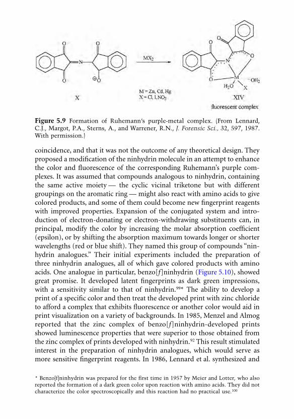
coincidence, and that it was not the outcome of any theoretical design. Theyproposed a modification of the ninhydrin molecule in an attempt to enhancethe color and fluorescence of the corresponding Ruhemann’s purple com-plexes. It was assumed that compounds analogous to ninhydrin, containingthe same active moiety — the cyclic vicinal triketone but with differentgroupings on the aromatic ring — might also react with amino acids to givecolored products, and some of them could become new fingerprint reagentswith improved properties. Expansion of the conjugated system and intro-duction of electron-donating or electron-withdrawing substituents can, inprincipal, modify the color by increasing the molar absorption coefficient(epsilon), or by shifting the absorption maximum towards longer or shorterwavelengths (red or blue shift). They named this group of compounds “nin-hydrin analogues.” Their initial experiments included the preparation ofthree ninhydrin analogues, all of which gave colored products with aminoacids. One analogue in particular, benzo[f]ninhydrin (Figure 5.10), showedgreat promise. It developed latent fingerprints as dark green impressions,with a sensitivity similar to that of ninhydrin.99* The ability to develop aprint of a specific color and then treat the developed print with zinc chlorideto afford a complex that exhibits fluorescence or another color would aid inprint visualization on a variety of backgrounds. In 1985, Menzel and Almogreported that the zinc complex of benzo[f]ninhydrin-developed printsshowed luminescence properties that were superior to those obtained fromthe zinc complex of prints developed with ninhydrin.92 This result stimulatedinterest in the preparation of ninhydrin analogues, which would serve asmore sensitive fingerprint reagents. In 1986, Lennard et al. synthesized and
Figure 5.9 Formation of Ruhemann’s purple-metal complex. (From Lennard,C.J., Margot, P.A., Sterns, A., and Warrener, R.N., J. Forensic Sci., 32, 597, 1987.With permission.)
* Benzo[f]ninhydrin was prepared for the first time in 1957 by Meier and Lotter, who alsoreported the formation of a dark green color upon reaction with amino acids. They did notcharacterize the color spectroscopically and this reaction had no practical use.100
0923Ch05Frame Page 192 Monday, May 14, 2001 12:30 PM

tested nine ninhydrin analogues for their ability to develop fingerprints andto afford luminescent complexes upon treatment with metal salts.101,102 Thereagent 5-methoxyninhydrin (XVI, Figure 5.10) was found to yield printsthat exhibited much more intensive fluorescence than with ninhydrin-devel-oped prints. The advantages of 5-methoxyninhydrin were discussed in detailby Almog and Hirshfeld.103 In 1987, it was adopted for operational use byIsraeli Police and had an immediate and remarkable success in solving anextortion case.103 A synthetic route to 5-methoxyninhydrin was also reportedby this group.104* That same year, Joullié, Cantu, and co-workers reported adifferent synthetic pathway to benzo[f]ninhydrin that affords higher yieldthan obtained by the former group.105
Further studies in this series showed that the ninhydrin structure is notessential for fingerprint development, and that vicinal triketones of othertypes also react in the same manner. The most important prerequisite is acyclic structure. Thus, compounds such as alloxan (V) and tetramethylcyclo-pentanetrione (XVII, Figure 5.11) also give a positive reaction with amino acidsand with latent fingerprints.106 Menzel, in 1989, demonstrated a time-resolved
Figure 5.10 Ninhydrin (I) and some of its analogues that were prepared andevaluated as fingerprint reagents: I, ninhydrin; XV, benzo[f]ninhydrin; XVI, 5-methoxyninyhdrin; XVIII, 5-methylthioninhydrin; XIX, thieno[f]ninhydrin; XX,5-(2-thienyl)ninhydrin; XXI, naphtho[f]ninhydrin.
* 5-Methoxyninhydrin has become commercially available under the name 2,2-dihydroxy-5-methoxy-1,3-indanedione (Aldrich Chemical Co., catalog no. 34 100-2).
0923Ch05Frame Page 193 Monday, May 14, 2001 12:30 PM

imaging system to suppress background luminescence of certain papers thatmay obscure fingerprint fluorescence. This was based on the observation thatthe lifetimes of natural paper luminescence are very short, whereas the life-times of the fingerprint fluorescence can be controlled by application ofappropriate fluorogenic reagents. Thus, when europium trichloride is usedas the metal salt in the secondary treatment stage, and benzo[f]ninhydrin asthe primary reagent, the fluorescence of the complex has a much longerlifetime than the background. By using a pulsed laser such as a copper-vaporlaser or specially arranged argon laser and appropriate electronic gating, itis possible to see only the fingerprint fluorescence after the backgroundluminescence has long decayed.107
Although the laser-induced fluorescence of latent fingerprints developedwith ninhydrin analogues greatly improved ninhydrin methodology, therewere still considerable difficulties in applying them to practical work. Mostof the analogues were not commercially available and the cost of those fewthat were available was extremely expensive. A number of research groups,particularly the joint effort of Joullié in Philadelphia and Cantu in Washing-ton, D.C., have started to explore the possibility of developing efficient, cost-effective syntheses of ninhydrin analogues and to evaluate them. This grouphas not only devised very elegant synthetic routes to ninhydrin analogues,but it has also produced some very efficient analogues. The list of ninhydrinanalogues that have been synthesized and evaluated since 1980 containsnearly 100 compounds. Most of these give a chromogenic reaction with aminoacids and some are also fluorogenic. Particularly good results have been obtainedwith ninhydrin analogues containing divalent sulfur, such as 5-methylthionin-hydrin,109-111 (XVIII), thieno[f]ninhydrin,111 (XIX), and 5-(2-thienyl)ninhy-drin,112 (XX, Figure 5.10). They exhibit good chromogenic as well as fluorogenicproperties with amino acids and with latent fingerprints. Sulfur derivatives ofninhydrin and ninhydrin analogues have been reported by Menzel andMekkaoui Alaoui to produce intensive luminescence after secondary treatmentwith europium and terbium salts.113-115 Selenium-containing analogues have
Figure 5.11 Vicinal cyclic triketones other than ninhydrin that also give chro-mogenic reaction with amino acids: V, alloxan; XVII, 4,4,5,5-tetramethylcyclo-pentanetrione.
0923Ch05Frame Page 194 Monday, May 14, 2001 12:30 PM

been prepared and evaluated as fingerprint reagents by Della, Kobus, and co-workers.116,117 Other analogues that have been prepared and tested as finger-print reagents are amino- and hydroxy-ninhydrins and a pyridine analogue(Almog et al.118,119), arylated ninhydrins (Joullié et al.111,120-122 and Dellaet al.116,117), a thiophene analogue (Joullié, Cantu, and co-workers123), two“ninhydrin dimers” (Joullié et al.124), a pyrazine analogue (Frank et al.125),and a phenyldiazo-ninhydrin (Della and Taylor116). Alkyl ninhydrins weresynthesized to obtain better solubility in nonpolar solvents (Hark andJoullié122 and Pounds126). The effect of various alkoxy groups on the solubilityand fluorogenicity of the analogues was recently reported by a joint team ofthe National Research Institute of Police Science and the PharmaceuticalInstitute of Tohoku University in Japan.127
A list of ninhydrin analogues that have been prepared and evaluated canbe found in Petrovskaia’s Ph.D. thesis.112 A comprehensive list of analogues,containing more than 80 compounds that have been published over the years,not only for fingerprint research, was recently composed by Hark.128
A joint team of the British PSDB and the Israel Police recently reportedthat the high hopes of benzo[f]ninhydrin had not been fulfilled. Despite thebetter contrast and fluorescence produced by this compound, the total num-ber of latent prints that could be visualized by it was less than with ninhy-drin.129 Also, the longer homologue of ninhydrin, naphtho[f]ninhydrin (XXI,Figure 5.10), reported by Hallman and Bartsch gave disappointing results. Itdid not produce any visible reaction with amino acids.130,131 Elber et al. haverecently used computational methods to study Ruhemann’s purple and anal-ogous compounds. They suggest a theoretical explanation for the limitedsuccess in improving the color of the developed prints. Based on theoreticalconsiderations, they have also designed new analogues that might affordmore intense colors with latent fingerprints. Their best “candidates” aremodified ninhydrin molecules, in which one or two of the side carbonyloxygens are replaced by either divalent sulfur or by methylene groups.132
These compounds have not yet been prepared.Ninhydrin derivatives that are not exactly “analogues” but that are also
used in fingerprint visualization are ninhydrin-hemiketals. Compounds ofthis type have been prepared by Takatsu et al. in Japan to substitute ninhydrinfor fingerprint development on thermal paper which is contaminated by theconventional ninhydrin formulations. The rationale behind their study isthat, like ninhydrin, its hemiketals might react with latent fingerprints, butthey are much more soluble than ninhydrin in nonpolar solvents. Indeed,the hemiketal derived from ninhydrin and 3,5,5-trimethyl-1-hexanol(Figure 5.12) in hexane solution developed good prints on thermal paperwithout any contamination.133 It is currently used by forensic science labo-ratories in Japan.91
0923Ch05Frame Page 195 Monday, May 14, 2001 12:30 PM

1,8-Diazafluorene-9-one (DFO)
In 1990, as a part of their search for new ninhydrin analogues, Grigg, Pounds,and co-workers modified the ninhydrin molecule even further. In additionto “regular” ninhydrin analogues, they also prepared and evaluated com-pounds that maintained only the essential functional group — the five-mem-bered ring with one carbonyl in the center and two adjacent dipoles on bothof its sides. One compound on their list, 1,8-diazafluorene-9-one [diazaflu-orenone or DFO, (XXII, Figure 5.13)], reacted with amino acids and withlatent fingerprints on paper to afford both color and fluorescence. Withamino acids it provided a red pigment whose structure closely resembledthat of Ruhemann’s purple134 (Figure 5.14).
A thorough mechanistic study by Wilkinson in Canada supported Grigg’sassumption134 that the NH proton in the product is mobile between thenitrogen atoms. It also indicated the formation of a transient hemiketal asthe active species in this reaction.135
Figure 5.12 Alkoxyninhydrin (ninhydrin hemiketal) currently used in Japan forfingerprint visualization on thermal paper. (From Takatsu, M. et al., Developmentof a new method to detect latent fingerprints on thermal paper with o-alkyl derivativeof ninhydrin, Report of the National Institute of Police Science, Japan, 44, 1, 1991.)
Figure 5.13 1,8-Diazafluorene-9-one (DFO) (XXII) and the anhydrous form ofninhydrin (IV). Notice the resemblance of the active moiety in both molecules.
0923Ch05Frame Page 196 Monday, May 14, 2001 12:30 PM

Latent fingerprints that were treated with DFO displayed only a faint redcolor but they luminesced brightly under green light (absorption maximumat about 470 nm and emission maximum at about 570 nm136). There was noneed for a secondary treatment with metal salt to induce luminescence, andthe total number of identifiable prints developed by it was considerablyhigher than with ninhydrin. These properties very quickly made DFO themost important fluorogenic reagent for latent fingerprints. The best formu-lation still uses Fluorisol as the main carrier solvent, but a thorough studyhas been initiated to find an acceptable alternative.137 The formulation pro-posed by the PSDB is a 0.025% solution of DFO in Fluorisol containing 3%methanol and 2% acetic acid. Optimal development conditions are 20 minat 100°C and no humidity.55 Stoilovic’s modification also included chloro-form in the mixture, and the final concentration of DFO was 0.04%.138 Anon-CFC formulation based on petrol ether as the main carrier was suggestedby Margot and Lennard.139 Its main disadvantage is high flammability.Another non-CFC formulation, based on tert-butylmethyl ether, was sug-gested by Geide.140 Conn, Lennard, and co-workers found that secondarytreatment with metal salts had only a negligible effect on the luminescencealthough metal complexes had been formed.141
Several attempts to obtain an improved DFO reagent by modifying itsmolecule (DFO analogues) were unsuccessful.134 There has been no follow-up to the observation of Frank and Handlin in 1993142 that two compoundsstructurally related to DFO, one of them dipyridyl ketone, produce verystrong fluorescence when reacted with amino acids. On the other hand, someketals derived from DFO to increase its solubility in nonpolar solvents doreact with latent fingerprints but not as well as DFO.143
At present, DFO is considered the best fluorogenic fingerprint reagentfor paper and porous surfaces, and it is used as the first stage of the chemicalsequence: DFO, ninhydrin, and PD.
Figure 5.14 The red pigment formed by the reaction of DFO with amino acids(XXIII). Notice the resemblance to Ruhemann’s purple (XII). (From Grigg, R.,Mongkolaussavaratana, T., Pounds, C.A., and Sivagnanam, S., 1,8-Diazafluorenoneand related compounds. A new reagent for the detection of alpha amino acids andlatent fingerprints, Tetrahedron Lett., 31, 7215, 1990.)
0923Ch05Frame Page 197 Monday, May 14, 2001 12:30 PM

1,2-Indanedione
The most recent, remarkable discovery in this field is 1,2-indanedione. Todevelop new routes to ninhydrin analogues, Joullié, Cantu, and co-workerssynthesized and evaluated another class of compounds closely related toninhydrin: 1,2-indanediones (Figure 5.15). These compounds were preparedand described in the chemical literature prior to Joullié, but never before hadthey been examined as potential amino acid or fingerprint reagents.
Methanolic solutions of various 1,2-indanediones were applied to aminoacid spots on filter paper. They afforded light pink stains that fluorescebrightly upon illumination with green light.144,145 Secondary treatment withzinc nitrate increased the fluorescence dramatically, particularly when5,6-dimethoxy-1,2-indanedione (XXIV, Figure 5.15) was used as a reagent.The fluorescence is stronger than with DFO-treated stains. Heat and humid-ity also have an augmentative effect on the fluorescence, but cooling to liquidnitrogen temperature is unnecessary.
Initial experiments with latent fingerprints under similar conditionsafforded brightly fluorescing fingerprint images.145
The effects of further structural modifications in the indanedione serieswere studied by Almog et al.; in their opinion, 1,2-indanedione itself, evenwithout secondary treatment, is at least as sensitive as DFO.146 They alsodevised a novel synthetic route to some indanediones147 that could not beprepared by the original method developed by Cava et al.148
The first positive experiments with indanediones were carried out inmethanolic solutions. Nevertheless, Petrovskaia and Joullié,112 Wilkinson,149
and Wiesner et al.150 recommend the use of indanedione in alcohol-freecarriers because alcohols (methanol, ethanol, isopropanol) reduce the effective-ness of the reagent due to the formation of hemiketals. Roux et al., however,
Figure 5.15 1,2-Indanedione (III) and some of its analogues that give fluorogenicreaction with amino acids and with latent fingerprints: III, 1,2-indanedione; XXIV,5,6-dimethoxyindanedione; XXV, 6-methoxy-1,2-indanedione (and other isomers);XXVI, 6-hydroxy-1,2-indanedione (and other isomers). (From Hauze, D.B., Petro-vskaia, O.G., Taylor, B., Joullié, M.M., Ramotowski, R., and Cantu, A.A., J.Forensic Sci., 43, 744, 1998; Wiesner, S., Optimization of the Indanedione Processfor Fingerprint Development, M.Sc. thesis, Casali Institute of Applied Chemistry,The Hebrew University of Jerusalem, Israel, 2001.)
0923Ch05Frame Page 198 Monday, May 14, 2001 12:30 PM

used methanol in their best formulation and did not notice any adverse effect.As opposed to Joullié,144,145 they did notice a positive effect of cooling theexhibits to liquid nitrogen temperature.151
Acetic acid was found to have a blurring effect on the developed printsand, hence, is not recommended for use in indanedione solutions.150 Afterchecking the various parameters, Wiesner et al. suggested a working solutioncomposed of 1,2-indanedione (0.2%) in HFE7100 solvent, containing about7% ethyl acetate.150 Preliminary observations indicate the following advan-tages of 1,2-indanedione over DFO:
1. Higher sensitivity (it detects more identifiable prints)2. Higher solubility in nonpolar solvents3. Good results in a non-CFC solvent (HFE7100)4. Cost
The reaction mechanism of 1,2-indanedione with amino acids wasexplored by Petrovskaia and Joullié, who suggest the formation of a 1,3-dipole(XXVII, Figure 5.16) as the fluorescent species.112
Wiesner et al.150 report that no new prints can be observed in a sequentialtreatment with ninhydrin after 1,2-indanedione. In the authors’ opinion, thisindicates a faster and more complete reaction of indanedione with aminoacids than the DFO reaction with amino acids (after which ninhydrin doesprovide new prints). Thus, the use of indanedione may save one stage in thesequence: DFO, ninhydrin, PD, which can turn to indanedione and PD.Several groups in Germany, Switzerland, the United Kingdom, Canada, theUnited States, Australia, and Japan have initiated extensive studies to evaluate1,2-indanedione for operational use. The Israel Police, Division of Identifi-cation and Forensic Science (DIFS), has already begun to use 1,2-indanedionein casework involving serious crimes.152
Figure 5.16 The fluorescent product of the reaction between 1,2-indanedioneand amino acid. (From Petrovskaia, O.G., Design and Synthesis of Chromogenicand Fluorogenic Reagents for Amino Acid Detection, Ph.D. thesis, University ofPennsylvania, Philadelphia, 1999.)
0923Ch05Frame Page 199 Monday, May 14, 2001 12:30 PM

References
1. Olsen, R.D., Scott’s Fingerprint Mechanics, Charles C Thomas, Springfield, IL,1978.
2. Pounds, C.A., Developments in fingerprint visualization, in Forensic ScienceProgress, Vol. 3, Springer-Verlag, Berlin, 1988.
3. Caton, H.C., Physical and chemical aspects of latent print development, inProc. Conf. Sci. Fingerprints, Police Scientific Development Branch, HomeOffice, London, 1974.
4. Chemical development of latent impressions, FBI Law Enforcement Bull., 39,8, 1970 (revised April 1976).
5. Udenfriend, S., Stein, S., Bohlen, P., Dairman, W., Leimgruber, W., andWeigele, M., A reagent for assay of amino acids, peptides, proteins and pri-mary amines in the picomole range, Science, 178, 871, 1972.
6. Mayer, S.W., Meilleur, C.P., and Jones, P.F., The use of orthophthalaldehyde forsuperior visualization of latent fingerprints, Identification News, 9, 13, 1977.
7. Lee, H.C. and Attard, A.E., Comparison of fluorescamine, o-phthalaldehyde,and ninhydrin for the detection and visualization of latent fingerprints, J.Police Sci. Admin., 7, 333, 1979.
8. Almog, J., Scope and limitations of the use of alloxan as a potential fingerprintreagent, Israel Police R&D Report DM/2037, Oct. 1982 (in Hebrew).
9. Almog, J., Rozen, S., and Scharf, G., Reaction of Naphthalene-2,3-Dicarbox-aldehyde with Amino Acids and with Latent Fingerprints on Paper, IsraelPolice R&D Report DM/2037, Sept. 1981 (in Hebrew).
10. Carlson, R.G., Srinivasachar, K., Givens, R., and Matuszewski, B.K., Newderivatizing agents for amino acids and peptides. 1. Facile synthesis of N-substituted 1-cyanobenz(f)isoindoles and their spectroscopic properties, J.Org. Chem., 51, 3979, 1986.
11. Roach, M.C. and Harmony, M.D., Determination of amino acids in subfem-tomole levels by high performance liquid chromatography with laser-inducedfluorescence detection, Anal. Chem., 59, 411, 1987.
12. Salares, V.R., Eves, C.R., and Carey, P.R., On the detection of fingerprints bylaser excited luminescence, Forensic Sci. Int., 14, 229, 1979.
13. Warrener, R.N., Kobus, H.J., and Stoilovic, M., An evaluation of the reagentNBD-chloride for the production of luminescent fingerprints on paper. I.Support for a xenon arc lamp being a cheaper and valuable alternative to anargon ion laser as an excitation source, Forensic Sci. Int., 23, 179, 1983.
14. Almog, A., Zeichner, A., Shifrina, S., and Scharf, G., Nitro-benzofurazanylethers — a new series of fluorigenic fingerprint reagents, J. Forensic Sci., 32,585, 1987.
15. Pounds, C.A. and Jones, R.J., The application of chemical techniques in thedevelopment of latent fingerprints, unpublished, 1982.
0923Ch05Frame Page 200 Monday, May 14, 2001 12:30 PM

16. Pounds, C.A. and Jones, R.J., Physicochemical techniques in the developmentof latent fingerprints, Trends Anal. Chem., 2, 180, 1983.
17. Ruhemann, S., Cyclic di- and triketones, J. Chem. Soc., 97, 1438, 1910.
18. Ruhemann, S., Triketohydrindene hydrate, J. Chem. Soc., 97, 2025, 1910.
19. Kaufmann, V., Über ein Analogon des indigos in der indenereihe:Diphtalyläthen, Ber. der D. Chem. Ges., 30, 382, 1897.
20. McCaldin, D.J., The chemistry of ninhydrin, Chem. Rev., 60, 39, 1960 (andreferences therein).
21. Schönberg, A. and Moubacher, R., Studies on indene derivatives. II. Triketo-hydrindene, J. Chem. Soc. 98, 71, 1943.
22. Dutt, M.C. and Poe, T.T., Use of ninhydrin as a spray reagent for the detectionof some basic drugs on thin-layer chromatography, J. Chromatogr., 195, 133,1980.
23. Schönberg, A. and Singer, E., Die Chemie des Ninhydrins und anderercyclisher 1,2,3-Tricarbonylverbindungen, Tetrahedron, 34, 1285, 1978.
24. Joullié, M.M., Thompson, T.R., and Nemeroff, N.H., Ninhydrin and ninhy-drin analogues. Syntheses and applications, Tetrahedron, 47, 8791, 1991.
25. Rubin, M.B. and Gleiter, R., The chemistry of vicinal polycarbonyl com-pounds, Chem. Rev., 100, 1121, 2000.
26. Ruhemann, S., Triketohydrindene hydrate. III. Its relation to alloxan, J. Chem.Soc., 99, 792, 1911.
27. Ruhemann, S., Triketohydrindene hydrate. IV. Hydrindantin and its ana-logues, J. Chem. Soc., 99, 1306, 1911.
28. Ruhemann, S., Triketohydrindene hydrate. V. The analogues of uramil andpurpuric acid, J. Chem. Soc., 99, 1486, 1911.
29. Schmidt, C.L.A., The Chemistry of Amino Acids and Proteins, Charles C Tho-mas, Springfield, IL, 1938.
30. Dent, C.E., A study of the behavior of sixty amino acids and other ninhydrin-reacting substances on phenol-“collidine” filter paper chromatograms withnotes as to the occurrence of some of them in biological fluids, Biochem. J.,43, 169, 1948.
31. Friedman, M. and Williams, L.D., Stoichiometry of formation of Ruhemann’spurple in the ninhydrin reaction, Bioorganic Chem., 3, 267, 1974.
32. Grigg, R., Malone, J.F., Mongkolaussavaratana, T., and Thianpatanagul, S.,Cycloaddition reactions relevant to the mechanism of the ninhydrin reaction.X-ray crystal structure of the protonated Ruhemann’s purple, a stable1,3-dipole, J. Chem. Soc., Chem. Commun., 421, 1986.
33. Bottom, C.B., Hanna, S.S., and Siehr, D.J., Mechanism of the ninhydrinreaction, Biochemical Ed., 6, 4, 1978.
0923Ch05Frame Page 201 Monday, May 14, 2001 12:30 PM

34. Grigg, R., Malone, J.F., Mongkolaussavaratana, T., and Thianpatanagul, S.,X�Y-ZH Compounds as potential 1,3-dipoles. 23. Mechanisms of the reac-tions of ninhydrin and phenalene trione with alpha amino acids. X-ray crystalstructure of protonated Ruhemann’s purple, a stable azomethine ylide, Tet-rahedron, 45, 3849, 1989.
35. Abderhalden, E. and Schmidt, H.S., Experiments with triketohydrindenehydrate, Hoppe Seyler’s Zeit. Physiol. Chem., 85, 143, 1913.
36. Oden, S. and von Hofsten, B., Detection of fingerprints by the ninhydrinreaction, Nature, 173, 449, 1954.
37. Oden, S., Developing Fingerprints, U.S. Patent 2715–571, August 16, 1955(Chem. Abstr., 49, 16276a, 1955).
38. Oden, S., Development of fingerprints, German Patent 934-850, November3, 1955.
39. Schlacke, K.H. and Fuchs, T., Allergic contact eczema to ninhydrin, Derm-Beruf-Umwelt, 37, 179, 1989.
40. Hytonen, M., Martimo, K.P., Estlander, T., and Tupasela, O., OccupationalIgE-mediated rhinitis caused by ninhydrin, Allergy, 51, 114, 1996.
41. Pirila, P., Estlander, T., Hytonen, M., Keskinen, H., Tupasela, O., and Tup-purainen, M., Rhinitis caused by ninhydrin develops into occupationalasthma. Eur. Respir. J., 10, 1918, 1997.
42. Morris, J.R. and Goode, G.C., NFN — an improved ninhydrin reagent fordetection of latent fingerprints, Police Res. Bull., 24, 45, 1974.
43. Crown, D.A., The development of latent fingerprints with ninhydrin, J. Crim.Law, Criminol. Police Sci., 60, 258, 1969.
44. Turbyfill, R.T., The development of latent fingerprints using non-flammableninhydrin mixture (London method), Crime Laboratory Digest (FBI), 76, 6,1976.
45. Morris, J.R., Extensions to the NFN (ninhydrin) reagent for the developmentof latent fingerprints, Unpublished, 1978.
46. Goode, G.C. and Morris, J.R., Latent Fingerprints: A Review of Their Origin,Composition and Methods for Detection, AWRE Report No. 022/83, UnitedKingdom (unclassified), Oct. 1983.
47. Tighe, D.J., Freon- plus two, Identification News, 34, 3, 1984.
48. Margot, P., Lennard, C., Stoilovic, M., Yong, S.J., and Warrener, R.N.,Improved detection of latent fingerprints, Proc. of the Third Workshop inAdvanced Fingerprint Techniques, Forensic Science Research Unit, ChemistryDepartment, Australian National University, Canberra, May 1986.
49. Kent, T., Ed., Manual of Fingerprint Development Techniques, ScientificResearch and Development Branch (SRDB), Home Office (U.K.), 1986.
50. Watling, W.J. and Smith, K.O., Heptane, an alternative to the freon ninhydrinmixture, J. Forensic Identification, 43, 131, 1993.
0923Ch05Frame Page 202 Monday, May 14, 2001 12:30 PM

51. Jungbluth, W.O., Replacement for CFC 113, J. Forensic Identification, 43, 226,1993.
52. Hewlett, D.F. and Sears, V.G., Replacement for CFC 113 in the ninhydrinprocess. 1, J. Forensic Identification, 47, 287, 1997.
53. Hewlett, D.F., Winfield, P.G.R., and Clifford, A.A., The ninhydrin process insupercritical carbon dioxide, J. Forensic Sci., 4, 487, 1996.
54. Hewlett, D.F., Sears, V.G., and Suzuki, S., Replacement for CFC 113 in theninhydrin process. 2, J. Forensic Identification, 47, 300, 1997.
55. Kent, T., Ed., Manual of Fingerprint Development Techniques, 2nd ed., PoliceScientific Development Branch (PSDB), Home Office, (U.K.), 1998.
56. Creer, K.E. and Brennan, J.S., The work of the serious crime unit, in Proc. ofthe Int. Forensic Symp. on Latent Fingerprints, FBI, FBI Academy, Quantico,VA, U.S. Government Printing Office, 1987.
57. Brennan, J.S., personal communication, Aug. 2000.
58. Taylor, S.C., Processing with ninhydrin fumes, Identification News, 29, 9, 1979.
59. Conway, J.P., Fingerprints and documents, in Proc. of the Joint Meeting of theAmerican Society of Questioned Document Examiners and the Crime DetectionLaboratories, Royal Canadian Mounted Police, Ottawa, Canada, 1965.
60. O’Hara, C.E., in Fundamentals of Criminal Investigation, Charles C Thomas,Springfield, IL, 1970.
61. Crown, D.A., Report on Conference on Latent Fingerprints, held at FBILaboratory, Washington, D.C., April 1965.
62. Mooney, D.G., Development of latent fingerprints and latent palmprints byninhydrin, Identification News, 16, 4, 1966.
63. Moenssens, A.A., in Fingerprint Techniques, Chilton, New York, 1971.
64. Lesk, J.A., Post-processing humidification in the development of latent fin-gerprints with ninhydrin, Am. Acad. Forensic Sci. Newslett., January, 1971,p. 7.
65. Miles, C., Use of Salt Solution to Control Relative Humidity During Devel-opment of Ninhydrin Plates, FIRS technical Report No. 5, Royal CanadianMounted Police (RCMP), Ottawa, Canada, 1987.
66. Rispling, O., Ninhydrin combats bank frauds, Int. Criminal Police Rev., 245,11, 1971.
67. Connor, C.M., Collaborative study of accelerated development of latent fin-gerprint images on paper by application of steam, J. Assoc. Official Anal.Chemists (AOAC), 59, 1003, 1976.
68. Brunelle, R.L., Report on forensic sciences, J. Assoc. Official Anal. Chemists(AOAC), 59, 354, 1976.
69. Morris, J.R., The application of a domestic steam iron for the developmentof latent fingerprints by the ninhydrin method, unpublished, 1978.
0923Ch05Frame Page 203 Monday, May 14, 2001 12:30 PM

70. Jones, R.J., Pounds, C.A., and Reed, R.A., personal communication, 1980.
71. Jones, R.J. and Pounds, C.A., Use of steam and heat to enhance fingerprintson papers other than cheques following development with ninhydrin, unpub-lished, 1981.
72. Margot, P., Lennard, C., Stoilovic, M., Yong, S.J., and Warrener, R.N., Newand improved fluorescent methods, in Proc. of the 2nd Workshop in AdvancedFingerprint Techniques, Forensic Science Research Unit, Chemistry Depart-ment, Australian National University, Canberra, Australia, July, 1984.
73. German, E.R., You are missing ninhydrin developed prints, IdentificationNews, 31, 3, 1981.
74. Morris, J.R., Goode, G.C., and Godsell, J.W., Some new developments in thechemical detection of latent fingerprints, Police Res. Bull., 21, 31, 1973.
75. Dalrymple, B.E., Duff, J.M., and Menzel, E.R., Inherent fingerprintluminescence — detection by laser, J. Forensic Sci., 22, 106, 1977.
76. Herod, D.W. and Menzel, E.R., Laser detection of latent fingerprints: ninhy-drin, J. Forensic Sci., 27, 200, 1982.
77. Herod, D.W. and Menzel, E.R., Laser detection of latent fingerprints: ninhy-drin followed by zinc chloride, J. Forensic Sci., 27, 513, 1982.
78. Kawerau, E. and Wieland, T., Conservation of amino-acid chromatograms,Nature, 168, 77, 1951.
79. Krauss, A., Anfärbung von Aminosäuren mit Metallsaltz-Ninhydrin-Gemis-chen, Z. Analyt. Chem., 229, 343, 1967.
80. Doi, E., Shibata, D., and Matoba, T., Modified colorimetric ninhydrin meth-ods for peptidase assay, Anal. Biochem., 118, 173, 1981.
81. Seitz, W.R., Fluorescence derivatization, in CRC Crit. Rev. Anal. Chem., 8,367, 1980.
82. Grove, E., Copper vapor lasers come of age, Laser Focus Mag., July 6, 1982.
83. Almog, J., Research and development of new fluorescors for forensic pur-poses, presented at the 67th Annu. Conf. Int. Assoc. Identification, Rochester,New York, July 1982.
84. Kobus, H.J., Stoilovic, M., and Warrener, R.N., A simple luminescent post-ninhydrin treatment for the improved visualization of fingerprints on docu-ments in cases where ninhydrin alone gives poor results, Forensic Sci. Int., 22,161, 1983.
85. Watkin, J.E., An intense blue light lamp for exciting fingerprint fluorescence,in Proc. Int. Fingerprint Conf., Scientific Research and Development Branch(SRDB), Home Office, London, November, 1984.
86. Watkin, J.E., Alternative lighting methods of detecting latent fingerprints, inProc. Int. Forensic Symp. Latent Fingerprints, FBI, FBI Academy, Quantico,VA, U.S. Government Printing Office, 1987.
0923Ch05Frame Page 204 Monday, May 14, 2001 12:30 PM

87. Kent, T., An operational guide to fingerprint techniques, in Proc. Int. Finger-print Conf., Scientific Research and Development Branch (SRDB), HomeOffice, London, November 1984.
88. Kent, T., Presentation on the methods used by the SRDB for fingerprintdevelopment, in Proc. Int. Symp. on Latent Fingerprints, FBI, FBI Academy,Quantico, VA, U.S. Government Printing Office, 1987.
89. Stoilovic, M., Kobus, H.J., Margot, P., and Warrener, R.N., Design of a versatilelight source for fingerprint detection and enhancement, in Proc. 9th AustralianInt. Meeting of Forensic Sciences, Melbourne, Australia, February 1986.
90. Stoilovic, M., Unilite 1: a versatile light system for fluorescence applications,especially those in forensic science, poster presented at the Int. Forensic Symp.on Latent Fingerprints, Forensic Science Research and Training Center, FBIAcademy, Quantico, VA, July 1987.
91. Suzuki, S., National Institute of Police Science, Japan, personal communica-tion, September 2000.
92. Menzel, E.R. and Almog, J., Latent fingerprint development by frequency-doubled neodymium:yttrium aluminium garnet (Nd:YAG) laser:Benzo[f]ninhydrin, J. Forensic Sci., 30, 371, 1985.
93. Stoilovic, M., Kobus, H.J., Margot, P., and Warrener, R.N., Improved enhance-ment of ninhydrin developed fingerprints by cadmium complexation usinglow temperature photoluminescent technique, J. Forensic Sci., 31, 432, 1986.
94. Menzel, E.R., Discussion of “Improved enhancement of ninhydrin developedfingerprints by cadmium complexation using low temperature photolumines-cence techniques,” and R.N. Warrener’s response, J. Forensic Sci., 32, 841, 1987.
95. Lennard, C.J., Margot, P.A., Sterns, A., and Warrener, R.N., Photoluminescentenhancement of ninhydrin developed fingerprints by metal complexation:structural studies of complexes formed between Ruhemann’s purple andgroup IIb metal salts, J. Forensic Sci., 32, 597, 1987.
96. Wieland, T., Die Trennung und Bestimmung der Naturlichen Aminosäuren,Fortschritte Chem. Forsch., 1, 211, 1949.
97. Davies, P.J., Taylor, M.R., and Wainwright, K.P., Zinc(II) chloride-methanolcomplex of 2-[(1,3-diketo-1,3-dioxo-2H-inden-2-ylidene)amino]1H-indene-1,3-(2H) dionate(1-) sodium salt: a complex of Ruhemann’s purple,Acta Cryst., C51, 1802, 1995.
98. Davies, P.J., Kobus, H.J., Taylor, M.R., and Wainwright, K.P., Synthesis andstructure of the zinc(II) and cadmium(II) complexes produced in the pho-toluminescent enhancement of ninhydrin developed fingerprints using group12 metal salts, J. Forensic Sci., 40, 565, 1995.
99. Almog, J., Hirshfeld, A., and Klug, J.T., Reagents for the chemical develop-ment of latent fingerprints: synthesis and properties of some ninhydrin ana-logues, J. Forensic Sci., 27, 912, 1982.
0923Ch05Frame Page 205 Monday, May 14, 2001 12:30 PM

100. Meier, R. and Lotter, H.G., Über Benz- und Naphthoindantrione, Chem. Ber.,90, 220, 1957.
101. Lennard, C.J., Margot, P.A., Stoilovic, M., and Warrener, R.N., Synthesis ofninhydrin analogues and their application to fingerprint development: pre-liminary results, J. Forensic Sci. Soc., 26, 323, 1986.
102. Lennard, C.J., Margot, P.A., Stoilovic, M., and Warrener, R.N., Synthesis andevaluation of ninhydrin analogues as reagents for the development of latentfingerprints on paper surfaces, J. Forensic Sci. Soc., 28, 3, 1988.
103. Almog, J. and Hirshfeld, A., 5-Methoxyninhydrin: a fingerprint developercompatible with the copper-vapor laser, presented at the Int. Forensic Symp.on Latent Fingerprints, FBI Academy, Quantico, VA, July 1987.
104. Almog, J. and Hirshfeld, A., 5-Methoxyninhydrin: a reagent for the chemicaldevelopment of latent fingerprints that is compatible with the copper-vaporlaser, J. Forensic Sci., 33, 1027, 1988.
105. Heffner, R., Safaryn, J.E., and Joullié, M.M., A new synthesis of benzo[f]nin-hydrin, Tetrahedron Lett., 28, 6539, 1987.
106. Almog, J., Reagents for chemical development of latent fingerprints: vicinaltriketones — their reaction with amino acids and with latent fingerprints onpaper, J. Forensic Sci., 32, 1565, 1987.
107. Menzel, E.R., Detection of latent fingerprints by laser-excited luminescence,Anal. Chem., 61, 557A, 1989.
108. Menzel, E.R., Fingerprints Detection with Lasers, 2nd ed., Marcel Dekker, NewYork, 1999.
109. Heffner, R. and Joullié, M.M., Synthetic routes to ninhydrins. Preparation ofninhydrin, 5-methoxyninhydrin and 5-(methylthio)ninhydrin, Synth. Com-mun., 21, 2231, 1991.
110. Almog, J., Hirshfeld, A., Frank, A., Grant, H., Harel, Z., and Ittah, Y., 5-Meth-ylthio ninhydrin and related compounds: a novel class of fluorogenic finger-print reagents, J. Forensic Sci., 37, 688, 1992.
111. Cantu, A.A., Leben, D.A., Joullié, M.M., Heffner, R.J., and Hark, R.R., Acomparative evaluation of several amino acid reagents for visualizing aminoacid (glycine) on paper, J. Forensic Identification, 43, 44, 1993.
112. Petrovskaia, O.G., Design and Synthesis of Chromogenic and FluorogenicReagents for Amino Acid Detection, Ph.D thesis (M.M. Joullié, supervisor),University of Pennsylvania, Philadelphia, 1999.
113. Mekkaoui Alaoui, I. and Menzel, E.R., Spectroscopy of rare earth-Ruhe-mann’s purple complexes, J. Forensic Sci., 38, 506, 1993.
114. Mekkaoui Alaoui, I. and Menzel, E.R., Emission enhancement in terbium-Ruhemann’s purple complexes, Forensic Sci. Int., 60, 203, 1994.
115. Mekkaoui Alaoui, I. and Menzel, E.R., Substituent effect on luminescenceenhancement in europium and terbium Ruhemann’s purple complexes,Forensic Sci. Int., 77, 3, 1996.
0923Ch05Frame Page 206 Monday, May 14, 2001 12:30 PM

116. Kobus, H.J., Pigou, P.E., Della, E.W., Taylor, B., and Davies, P.J., Fingerprintresearch in South Australia, in Proc. Int. Symp. on Fingerprint Detection andIdentification, Ne’urim, Israel, Almog, J. and Springer, E., Eds., Hemed Press,1995, 227.
117. Della, E.W., Janowski, W.K., Pigou, P.E., and Taylor, B.M., Synthesis of fin-gerprint reagents: aromatic nucleophilic substitution as a route to 5-substi-tuted ninhydrins, Synthesis, 12, 2119, 1999.
118. Almog, J., Hirshfeld, A., Frank, A., Sterling, J., and Leonov, D., Aminonin-hydrins: fingerprint reagents with direct fluorogenic activity — preliminarystudies, J. Forensic Sci., 36, 104, 1991.
119. Almog, J., unpublished results (see Ref. 111).
120. Hark, R.R., Hauze, D.B., Petrovskaia, O., Joullié, M.M., Jaouhari, R., andMcKomiskey, P., Novel approaches toward ninhydrin analogs, TetrahedronLett., 35, 7719, 1994.
121. Hark, R.R., Hauze, D.B., Petrovskaia, O., and Joullié, M.M., Chemical detec-tion of fingerprints — synthesis of arylated ninhydrin analogs, in Proc. Int.Symp. on Fingerprint Detection and Identification, Ne’urim, Israel, Almog, J.and Springer, E., Eds., Hemed Press, 1995, 129.
122. Hark, R.R., Synthesis of Ninhydrin Analogs, Ph.D thesis (M.M. Joullié,supervisor), University of Pennsylvania, Philadelphia, 1996.
123. Hauze, D.B., Joullié, M.M., Ramotowski, R., and Cantu, A., Novel synthesisof thianinhydrin, Tetrahedron, 53, 4239, 1997.
124. Hauze, D.B., Petrovskaia, O., Joullié, M.M., and Hark, R.R., New reagents forthe development of fingerprints, in Proc. Int. Symp. on Fingerprint Detectionand Identification, Ne’urim, Israel, Almog, J. and Springer, E., Eds., HemedPress, 1995, 119.
125. Frank, F.J., Borup, B., Brookman, J.A., Carr, A.J., Hurd, K.L., Renner, M., andStowell, J.K., Preparation of ninhydrin analogs for fluorescent fingerprintdevelopment, poster presented at “Spectrum 91,” Int. Symp. Forensic Tech-niques, Detroit, Michigan, 1991.
126. Pounds, C.A., unpublished results (see Ref. 24).
127. Ohta, H., Suzuki, Y., Sugita, R., Suzuki, S., and Ogasawara, K., Examinationof 5-alkoxyninhydrins as latent fingerprint visualization reagents, Can. Soc.Forensic Sci. J., submitted for publication, 2000.
128. Hark, R.R., Table of ninhydrin analogs, personal communication, Sept. 2000.
129. Almog, J., Sears, V.J., Springer, E., Hewlett, D.F., Walker, S., Wiesner, S., Lidor,R., and Bahar, E., Reagents for the chemical development of latent finger-prints: scope and limitations of benzo[ f ]ninhydrin in comparison to ninhy-drin, J. Forensic Sci., 45, 538, 2000.
130. Hallman, J.L. and Bartsch, R.A., Synthesis of naphthoninhydrin, J. Org.Chem., 56, 6423, 1991.
131. Almog, J. and Springer, E., unpublished results, 1993.
0923Ch05Frame Page 207 Monday, May 14, 2001 12:30 PM

132. Elber, R., Frank, A., and Almog, J., Chemical development of latent fingerprints:computational design of ninhydrin analogues, J. Forensic Sci., 45, 757, 2000.
133. Takatsu, M., Kageyama, H., Hirata, K., Akashi, T., Yoko Ta, T., Shiitani, M.,and Kobayashi, A., Development of a new method to detect latent fingerprintson thermal paper with o-alkyl derivative of ninhydrin, Report of the NationalInstitute of Police Science, Japan, 44, 1, 1991.
134. Grigg, R., Mongkolaussavaratana, T., Pounds, C.A., and Sivagnanam, S.,1,8-Diazafluorenone and related compounds. A new reagent for the detectionof alpha amino acids and latent fingerprints, Tetrahedron Lett., 31, 7215, 1990.
135. Wilkinson, D., Study of the reaction mechanism of 1,8-diazafluoren-9-onewith the amino acid L-alanine, Forensic Sci. Int., 109, 87, 2000.
136. Hardwick, S., Kent, T., Sears, V., and Winfield, P., Improvements to theformulation of DFO and the effects of heat on the reaction with latentfingerprints, Fingerprint Whorld, 19, 65, 1993.
137. Hewlett, D.F. and Sears, V.J., Formulation of amino acid reagents. Search for asafe effective replacement for CFCs, in Proc. Int. Symp. on Fingerprint Detectionand Identification, Almog, J. and Springer, E., Eds., Ne’urim, Israel, 99, 1995.
138. Stoilovic, M., Improved method for DFO development of latent fingerprints,Forensic Sci. Int., 60, 141, 1993.
139. Margot, P. and Lennard, C., Fingerprint Detection Techniques, 6th revisededition, Université de Lausanne, 1994.
140. Geide, B., Detection of latent fingerprints — DFO without CFC, in Proc. Int.Symp. on Fingerprint Detection and Identification, Almog, J. and Springer, E.,Eds., Ne’urim, Israel, 1995, 95.
141. Lennard, C., The effect of metal salt treatment on the photoluminescence ofDFO-treated fingerprints, personal communication,1999.
142. Frank, F.J. and Handlin, N., Development of a latent fingerprint detectionchemical: dibenzo-1,8-diazafluorenone, M.A.F.S. Newslett., 22, July 1993.
143. Frank, A., Grant, H., and Almog, J., Preliminary Tests on the Use of Two NewKetals of DFO for the Development of Latent Fingerprints, presented in aclosed meeting on advances in fingerprint detection, PSDB, Home Office,U.K., 1996.
144. Ramotowski, R., Cantu, A.A., Joullié, M.M., and Petrovskaia, O.G.,1,2-Indanedione: a preliminary evaluation of a new class of amino acid visu-alizing compounds, Fingerprint Whorld, 23, 131, 1997.
145. Hauze, D.B., Petrovskaia, O.G., Taylor, B., Joullié, M.M., Ramotowski, R., andCantu, A.A., 1,2-Indanediones: new reagents for visualizing the amino acidcomponents of latent prints, J. Forensic Sci., 43, 744, 1998.
146. Almog, J., Springer, E., Wiesner, S., Frank, A., Khodzhaev, O., Lidor, R., Bahar,E., Varkony, H., Dayan, S., and Rozen, S., Latent fingerprint visualization by1,2-indanedione and related compounds: preliminary results, J. Forensic Sci.,44, 114, 1999.
0923Ch05Frame Page 208 Monday, May 14, 2001 12:30 PM

147. Dayan, S., Almog, J., Khodzhaev, O., and Rozen, S., A novel synthesis ofindanediones using the HOF.CH3CN complex, J. Org. Chem., 63, 2752, 1998.
148. Cava, M.P., Little, R.L., and Napier, D.R., Condensed cyclobutane aromaticsystems. V. The synthesis of some alpha-diazoindanones: ring contraction inthe indane series, J. Am. Chem. Soc., 80, 2257, 1958.
149. Wilkinson, D., Spectroscopic study of 1,2-indanedione, Forensic Sci. Int., 114,123, 2000.
150. Wiesner, S., Optimization of the Indanedione Process for Fingerprint Devel-opment, M.Sc. thesis, (J.Almog and Y.Sasson, supervisors), Casali Instituteof Applied Chemistry, The Hebrew University of Jerusalem, Israel, 2001.
151. Roux, C., Jones, N., Lennard, C., and Stoilovic, M., Evaluation of1,2-indanedione for the detection of latent fingerprints on porous surfaces,J. Forensic Sci., 45, 761, 2000.
152. Azoury, M. (Head, Latent Fingerprint Development Laboratory, IsraelPolice), personal communication, July 2000.
0923Ch05Frame Page 209 Monday, May 14, 2001 12:30 PM

Fingerprint Detection with Photoluminescent Nanoparticles
E. ROLAND MENZEL
Contents
The Essence of Time-Resolved ImagingLuminescence LifetimesBasics of Time-Gated Fingerprint DetectionBasics of Phase-Resolved Imaging
Fingerprint TreatmentsLanthanide-Based ProceduresPhotoluminescent Semiconductor Nanocomposites
CdS NanocrystalsCdS/Dendrimer NanocompositesDiimide Mediation of Fingerprint Development with CdS/Dendrimer NanocompositesIncorporation of Lanthanide Complexes into DendrimersCadmium Selenide Nanocrystals
Ongoing InvestigationsReferences
The exploitation of photoluminescence as a general approach to the detectionof latent fingerprints began in 1976.
1
The rationale for the photoluminescenceapproach is the very high analytical sensitivity that photoluminescence tech-niques provide quite generally. One cannot do better than the detection ofa single photon, a capability within reach in photoluminescence. Fingerprintluminescence excitation initially used lasers, but filtered lamps (these daysreferred to as alternate or alternative light sources) were employed as well,albeit at the expense of detection sensitivity in comparison with lasers. Thissensitivity discrepancy still pertains today. The initial fingerprint photolumi-nescence investigation focused on fluorescence inherent to fingerprint resi-due. However, the utilization of fluorescent dusting powders and stainingdyes, as well as reagents that would attack fingerprint constituents to yield afluorescent product, was also anticipated from the outset. By the late 1970s,
6
0923Ch06Frame Page 211 Monday, May 14, 2001 3:22 PM

various fluorescent dusting powders had been developed.
2
Dye staining, firstdemonstrated in 1976,
1
came into its own in the early 1980s in concert withcyanoacrylate ester fuming.
3
This staining is today one of the most successfulphotoluminescence procedures for detection of fingerprints on smooth sur-faces, regardless of the age of the fingerprint. Numerous staining dyes can beemployed. The post-treatment of ninhydrin-developed latent fingerprints byzinc chloride, first reported in 1982,
4
made fingerprints on porous items(mostly paper) tractable as well, and is today quite routine. Sensitivityimprovements to this procedure, involving ninhydrin analogs, notablybenzo(
f
)ninhydrin
5
and 5-methoxyninhydrin
6
followed. The zinc chloridepost-treatment of ninhydrin-processed fingerprints was until very recentlyunsurpassed in terms of the intensity of the obtained photoluminescence.However, recent work carried out in Japan has identified indium chloride asbeing superior.
7
The InCl
3
is used in the same way as ZnCl
2
. Figure 6.1 depictsan example of the comparison of ZnCl
2
vs. InCl
3
treatment of a ninhydrin-processed fingerprint. More intense luminescence can be obtained with GaCl
3
because Ga has a lower atomic number than In. However, GaCl
3
reacts fairlyviolently with water (which occurs in methanol that has been exposed toambient air). Thus, GaCl
3
is not as practical as InCl
3
. Diazafluore-9-one is arelatively recent reagent that can be used instead of ninhydrin/zinc chloride.
8
It is now routinely employed in a number of crime laboratories. With theabove procedures, and a number of others for special situations,
9
photolu-minescence detection of fingerprints has assumed a prominent place world-wide as a major routine methodology. Photoluminescence detection of latent
Figure 6.1
Ninhydrin/ZnCl
2
vs. ninhydrin/InCl
3
fingerprint photoluminescencedevelopment.
0923Ch06Frame Page 212 Monday, May 14, 2001 3:22 PM

fingerprints has been instrumental in the solution of many major cases (e.g.,Polly Klaas, Nightstalker). To the best of this author’s knowledge, laser detec-tion holds the record for the oldest fingerprint developed and identified ina criminal case over 40 years old.
10
In the author’s laboratory, ridge detail offingerprints dating back to the American Civil War has been developed bylaser. The photoluminescence approach has found use also in other crimi-nalistic applications,
9
such as document examination, fiber analysis, locatingseminal fluid, and various instances of trace evidence detection.
11
The currentstate of the methodology has been dealt with extensively in journals as wellas books, including the first edition of
Advances in Fingerprint Technology.
12
Thus, the focus in this second edition is on upcoming methodologiesdesigned to permit detection of latent fingerprints on articles that displayvery intense background luminescence which masks the fingerprint lumines-cence obtained with the current procedures. This is a pervasive major prob-lem that still plagues the photoluminescence detection of fingerprints and,indeed, all photoluminescence-based analytical techniques.
The Essence of Time-Resolved Imaging
Whether in analytical chemistry, biotechnology, or criminalistics, the detec-tion of a weak photoluminescence in the presence of a strong backgroundfluorescence is carried out following the same basic principles. They makeuse of the difference between the luminescence lifetimes of the backgroundand analyte emissions. We begin by inquiring into the origin of this lifetimedifference.
Luminescence Lifetimes
9
The emission of light by substances can have a number of causes, amongthem heat (incandescence) and chemical reaction (chemiluminescence), asin the luminol reaction with blood. For our purposes, the most importantorigin of luminescence, however, is the prior absorption of light (excitation)to give rise to photoluminescence. On the basis of luminescence lifetime (i.e.,the decay time of the luminescence intensity once the excitation is cut off)two categories of photoluminescence were distinguished long before thequantum-mechanical underpinnings were understood; namely fluorescenceof short lifetime and phosphorescence of long lifetime. The slowness conceptdistinguishing the two light emissions has evolved over time (toward shorterlifetimes of phosphorescence). The distinction between fluorescence andphosphorescence is placed on a less arbitrary footing when one examines thequantum-mechanical origin of the photoluminescence of typical organicmolecules — which we are mostly concerned with in fingerprint work. For
0923Ch06Frame Page 213 Monday, May 14, 2001 3:22 PM

purposes of understanding their photoluminescence, these molecules can bethought of to good approximation as being two-electron systems. When themolecule is in the ground (unexcited) state, the two optically active electronsoccupy the same molecular orbital, namely, the highest occupied molecularorbital (HOMO). Their spins must be antiparallel to satisfy the exclusionprinciple. The total spin (S) of the two electrons, namely the sum of the twospins (1/2 each), is thus zero and the spin multiplicity (2S + 1) is 1. The stateis, accordingly, a singlet state. On optical excitation, one of the electrons ispromoted to a molecular orbital of higher energy via the absorption of theexcitation illumination, namely, to the lowest unoccupied molecular orbital(LUMO). The molecule is now in the excited state that gives rise to photo-luminescence. If no electron spin flip has taken place during the excitationprocess, the excited state is still a singlet state and the decay to the singletground state (i.e., electron jump back to HOMO), accompanied by emission oflight, is termed
fluorescence
. If a spin flip has taken place, however, which is legalin terms of the exclusion principle because the two electrons no longer occupythe same orbital, the excited state becomes a triplet state (S = 1, 2S + 1 = 3) andthe decay to the singlet ground state is termed
phosphorescence
. The distinc-tion between fluorescence and phosphorescence on the basis of electron spinsis traced back to the nature of the electric dipole operator that describes theemission of light. It does not operate on spin. Thus, an allowed transition,namely one that can occur quickly, one that comes with a short lifetime,involves ground and excited states of the same spin multiplicity (2S + 1).When the spin multiplicities of the two states differ, the transition is forbid-den and thus does not occur quickly; hence, a long lifetime. This definitionof fluorescence and phosphorescence is not universally followed. For exam-ple, the luminescences of lanthanides are often (sloppily) referred to as flu-orescences although the spin multiplicities of the involved states differ byeven more than discussed above, and the lifetimes of lanthanide lumines-cences are very long compared to typical fluorescence lifetimes. Recombina-tion and trap luminescences, as found in semiconductor materials, are adifferent matter still. In this chapter we reserve the term “fluorescence” tothe transition between molecular singlet states. Other transitions are referredto by the catch-all terms “luminescence” and “emission,” or are called “phos-phorescence” when appropriate according to the above-described criterion.
Basics of Time-Gated Fingerprint Detection
Suppose a latent fingerprint has been treated such that it phosphoresces andassume that it is located on a fluorescent article. Now illuminate the articlewith an appropriate laser (filtered lamps are generally not useful for time-resolved fingerprint detection) that is periodically turned on and off andassume there is on hand an imaging device that can be turned on and off
0923Ch06Frame Page 214 Monday, May 14, 2001 3:22 PM

synchronously with the laser. One then has the scheme depicted in Figure 6.2,in which the gate width denotes the time the imaging device is on and thegate delay represents the time interval between laser cut-off and imagingdevice turn-on. The delay is needed to ensure that the background fluores-cence has decayed by the time the imaging device becomes active. The imag-ing device turns off before onset of the next laser illumination cycle.
Theimaging device is typically a gateable CCD camera, namely a CCD cameraequipped with a proximity-focused microchannel plate image intensifier.
9,13
Figure 6.3 shows a typical block diagram of the pertinent imaging apparatus.The system depicted in the figure utilizes a mechanical light chopper, namelya rotating wheel with holes in it. This is appropriate when the fingerprintluminescence has a lifetime of millisecond order. The system in Figure 6.3calls for a laser of relatively high power, such as the Ar-laser typicallyemployed in current routine fingerprint work. One can operate with muchsmaller lasers in systems in which fingerprints are scanned by a focused laserbeam that is deflected by a pair of rotating mirrors,
14
in much the same wayas the electron beam rastering in the acquisition of television images. Suchsystems tend to be slow, but have the virtue, apart from the small laser, ofrequiring only a cheap detector, such as a photomultiplier tube, instead ofthe expensive gateable CCD camera. For shorter lifetimes, which are beyondthe capability of mechanical devices, an electro-optic light modulator orsimilar device would replace the light chopper. Now, however, optical align-ment and electrical biasing of the modulator make for difficulties as well as
Figure 6.2
Time-gating scheme for time-resolved imaging to suppress back-ground fluorescence.
laser onbackgroundfluorescence
on fingerprintphosphoresc.
off off
offon on
image intens.off
gate width
gatedelay
0923Ch06Frame Page 215 Monday, May 14, 2001 3:22 PM

increased expense. For time-resolved imaging in such situations, a differentapproach is often taken. Time-gated imaging typically pertains to the domainof lifetimes longer than roughly 1 µs.
Basics of Phase-Resolved Imaging
Note that a fingerprint detection system based on the phase-resolved concepthas yet to be developed. However, this is just a matter of time, given thatphase-resolved imaging systems have been in operation for some time inapplications such as cell microscopy. If one modulates the intensity of theilluminating laser light sinusoidally instead of on-off as in Figure 6.2, thethus excited luminescence is then also sinusoidal in intensity but is delayedwith respect to the excitation by a phase that is related to the luminescencelifetime. There is also a related luminescence demodulation. The situation isshown in Figure 6.4, with normalized excitation and emission.
φ
is the phaseand m the demodulation. The effect of the angular modulation frequency
ω,
namely 2
π
f (where f is the modulation frequency), on the phase and demod-ulation is depicted in Figure 6.5. Multiple luminescence lifetimes in phase-resolved spectroscopy and imaging can be distinguished by varying the mod-ulation frequency. Modulation frequencies of hundreds of megaHertz arereadily obtainable. Thus, lifetimes of nanosecond order become accessible.It is only necessary that the analyte luminescence have a lifetime significantlydifferent from that of the background for phase-resolved imaging to suppressthe background. However, the fingerprint luminescence lifetime will gener-ally be longer in practise than that of the background because shortening ofluminescence lifetime is generally attended by decrease in luminescencequantum yield (i.e., decrease in luminescence intensity). The desired finger-print luminescence lifetimes typically range from about 10 ns to about 1 µs(as compared to background fluorescence lifetimes of roughly 1 ns). A basic
Figure 6.3
Block diagram of time-gated imaging apparatus.
lens
light chopper
computer
Ar-laser
image monitor
printer
filter
gateableCCDcamera
sample
liquidlightguide
0923Ch06Frame Page 216 Monday, May 14, 2001 3:22 PM

block diagram of the pertinent imaging apparatus is shown in Figure 6.6.More sophisticated versions are described elsewhere.
9
Here, one is primarilyconcerned with fingerprint treatments that yield luminescence lifetimesappropriate to the time-gated and phase-resolved domains, rather than thedetails of instrumentation.
Figure 6.4
Phase shift and demodulation of luminescence vs. excitation (
Φ
=phase shift,
ω
= modulation angular frequency,
τ
= luminescence lifetime, m =demodulation).
Figure 6.5
Phase and demodulation vs. modulation angular frequency.
fluorescenceexcitation
b
time
B
inte
nsi
tyφ
tan φ = ωτ m = b/B = (1 + ω2τ2 )-1/2
1
m φ
0 0
900
ω
0923Ch06Frame Page 217 Monday, May 14, 2001 3:22 PM

Fingerprint Treatments
Fingerprint treatments suitable for time-resolved imaging began to beexplored in the late 1980s. At first, transition metal complexes that yieldcharge-transfer phosphorescences were successfully examined and applied tofingerprint development by dusting or staining.
15
However, such complexescould not be utilized for chemical fingerprint development, thus limiting theapproach primarily to smooth surfaces. Next, lanthanide-based procedureswere explored. These have the potential of forming a universal photolumi-nescence approach to fingerprint detection, being applicable, in principle, toall types of surface and to fingerprints of any age. They have by now reacheda reasonable level of maturity. However, problems persist with the lanthanide(rare earth) approaches, thus prompting more recent investigation of pho-toluminescent semiconductor nanocomposites.
Lanthanide-Based Procedures
The concept of time-resolved fingerprint detection for purposes of back-ground fluorescence suppression actually dates back to 1979.
16
Its feasibilitythen was explored using a rotating cylinder with slots cut into it to turn thelaser illumination on and off. The photographic camera was placed such thatthe sample would come into its view at a time after laser cut-off, as shownin Figure 6.7. The arrangement resembles a phosphoroscope, a device thatdates back to the 19th century. The sample was a fingerprint dusted with apowder that contained a Tb
3+
complex, yielding a green luminescence ofmillisecond-order lifetime. The fingerprint was located on yellow notepad
Figure 6.6
Block diagram of phase-shift/demodulation apparatus for time-resolvedimaging.
laser
computer
sinewavegenerator
delayCCD
MCP
modulator fingerprintsample
0923Ch06Frame Page 218 Monday, May 14, 2001 3:22 PM

paper, which yields a very intense greenish yellow fluorescence. The feasibilityof background elimination was demonstrated with the apparatus and sample.However, practicality was lacking, in the sense that the size of the rotatingcylinder limits the size of the article to be examined, given that the articlemust fit inside the cylinder. The apparatus cannot be sufficiently scaled upin size for general purposes because of limitations in rotation speed of thecylinder, as well as decreased camera image resolution with increasing cylin-der size. The practicality issue was resolved in the early 1990s with a time-gated system as depicted in Figure 6.3. The corresponding fingerprint treat-ments at first involved lanthanide chemistries in which the zinc chloride post-ninhydrin step was replaced by a lanthanide halide (typically EuCl
3
orTbCl
3
).
17
Subsequently, lipid-specific chemistries were explored.
18
Dustingand staining procedures involving lanthanide complexes were developed inthe early to mid-1990s. The various lanthanide procedures are detailed in
Fingerprint Detection with Lasers, 2nd ed., revised and expanded.
9
The basicunderpinnings of the lanthanide general strategy will thus only be brieflyoutlined. For chemical fingerprint processing, the general features of theinvolved lanthanide complexes are shown in Figure 6.8. The conjugatingligand serves to selectively bind to the fingerprint, and the complex of step1 in the figure is nonluminescent. The sensitizing ligand, attached subse-quently, produces the lanthanide luminescence by absorbing the excitation
Figure 6.7
Phosphoroscope-like apparatus for time-resolved imaging.
incident laserlight
rotating cylinder
sample
photographiccamera
0923Ch06Frame Page 219 Monday, May 14, 2001 3:22 PM

light and transferring the excitation energy to the lanthanide ion by an energytransfer process akin to Forster intermolecular energy transfer.
9
For dustingand staining, the conjugating ligand is not needed. Figure 6.9 shows theenergy-transfer scheme for europium complexes.
9
At the time of this writing,problems associated with chemical processing of fingerprints older than about1 week still persist. Furthermore, the excitation of lanthanide complexesdemands ultraviolet (UV) light and thus is not compatible with many lasersystems currently in use in fingerprint laboratories. An ultraviolet-capableargon-ion laser is a suitable excitation source. When time-resolved imagingis not mandatory — namely, when background fluorescence is not aproblem — the fingerprint work can utilize an ordinary UV lamp. Explora-tion of fingerprint processing with photoluminescent semiconductor nano-particles as well as dendrimer application to fingerprint development wereinitiated about a year ago to remedy the above problems. These nanoparticleapproaches are promising, especially in the time-resolved context, and aretaken up in the remainder of this chapter. It is anticipated that they will formthe next milestone in fingerprint detection methodology.
Photoluminescent Semiconductor Nanocomposites
Semiconductor materials such as CdS, CdSe, CdTe, InP, and InAs, which nor-mally are not luminescent, can become intensely luminescent when particles,
Figure 6.8
Basic scheme for lanthanide-based chemical fingerprint development.
conjugatingligand
lanthanide
fingerprint
step 1
step 2
step 3
sensitizingligand
0923Ch06Frame Page 220 Monday, May 14, 2001 3:22 PM

typically in crystalline form, become very small (i.e., of nanometer order insize). Such nanoparticles can be quite robust. They are typically encapsulatedwith ZnS, silica, or organic material. This capping is sometimes referred toalso as derivatization or functionalization, especially when an organic com-pound is involved, which is sometimes also referred to as a surfactant. Theencapsulation amounts to covering the nanocrystal with a layer of materialthat may serve a variety of functions, for example, passivation to optimizeluminescence efficiency, serving as a site for attachment of conjugatingligands designed for specificity of chemical binding, serving this labeling func-tion itself, serving to solubilize the nanocrystal, and preventing aggregation of
Figure 6.9
Ligand-to-europium energy transfer and europium luminescenceenergy-level diagram (waved arrows denote radiationless transitions and straightarrows radiative ones).
sensitizingligand
5 D0
7 F2
7 F17 F0
Eu 3 +
0923Ch06Frame Page 221 Monday, May 14, 2001 3:22 PM

nanocrystals. Photoluminescent semiconductor nanoparticles have recentlybecome the subject of intense investigation in the biotechnology arena,mostly for labeling purposes.
19,20
DNA sequencing is an example. The salientvirtues that distinguish the nanoparticles (referred to also as quantum dots,nanocrystals, and nanocomposites, depending on morphology) from ordi-nary fluorescent labels are that their absorption and luminescence wave-lengths (colors) can be tuned by varying the particle size and that the lumi-nescence lifetimes are long, ranging from roughly 10
–8
to 10
–6
s, thus makingthe nanoparticles suitable for time-resolved spectroscopy and time-resolvedimaging, with flexibility in terms of useful laser light sources. These featuresare valuable from a biotechnology perspective and are, in principle, equallypertinent to the fingerprint context, thus prompting a study of their potentialutility in fingerprint detection that commenced in 1999.
9
Because of financialand manpower constraints, this investigation has to date only aimed at reduc-tion to practice
21
(i.e., demonstration of feasibility rather than work-up ofroutine recipes). Nonetheless, a variety of nanoparticle systems and finger-print chemistries have been examined. Practical recipes will presumably fol-low once the best general approaches have been delineated.
CdS Nanocrystals
22
Photoluminescent semiconductor nanocrystals may be expected to be usedfor fingerprint detection in various ways, namely by incorporation into dust-ing powder in a manner akin to fluorescent dye blending with magneticpowder
9
by staining, especially once fingerprints have been exposed tocyanoacrylate ester; or by chemical bonding to constituents of fingerprintresidue. In photoluminescence detection of fingerprints, the stainingapproach generally tends to be more effective when applicable to the articleunder examination, than dusting. Thus, the focus in this chapter section ison staining with CdS nanocrystals. As a preface to this mode of fingerprintdetection, the photophysical properties of CdS quantum dots are examined,primarily to assess suitability for phase-resolved imaging to suppress back-ground fluorescence, but also to determine suitable excitation wavelengths.
The employed CdS nanocrystal samples, prepared in inverse micelles
23,24
and capped with dioctyl sulfosuccinate (sodium salt), were obtained fromProfessor John T. McDevitt (Chemistry Department, University of Texas,Austin). Solubilization of the nanocrystals utilized heptane or a mixture ofhexanes (CH
3
C
4
H
8
CH
3
). Solutions had quantum dot concentrations of mil-ligram/milliliter order. Absorption spectra in these solvents exhibited bandedges at about 440 nm and very broad absorbance (with some structure, butnot absorption peaks as in typical atomic or molecular spectra) that increasedwith decreasing wavelength to 300 nm, the lowest wavelength in our absorp-tion measurements. The spectra, fairly typical of semiconductor absorption
0923Ch06Frame Page 222 Monday, May 14, 2001 3:22 PM

spectra, are shown in Figure 6.10. They serve to determine the sizes of thenanocrystals,
23
which were deduced to have radii of 3 to 4 nm. The nano-crystal luminescence (band width about 100 nm) peaked at about 580 nm,with a second, weaker luminescence band in the 400 to 450-nm range. Interms of intensities as a function of excitation power, excitation wavelength,solvent system, etc., the luminescence spectroscopy of nanocrystals tends tobe more complex than that of typical fluorescent molecules because in nano-crystals one likely has a number of different, and quite variable, trap statesthat contribute to the luminescence, including surface traps, as well as theintrinsic semiconductor recombination process. Thus, the spectroscopic fea-tures generally need to be examined for the samples at hand, with literatureresults serving as approximate guides only. Lifetime measurements for hep-tane solution used phase-shift/demodulation techniques, as described earlier,and employed a HeCd laser (operating at 325 nm). The lifetime measurementcorresponded to the total luminescence (transmitted to the detector througha long-wavelength-pass filter). Laser modulation frequencies ranged from 0.1to 100 MHz. The fit to the obtained phase shift and demodulation curves,analogs to the curves shown in Figure 6.5, yielded three lifetime components.Approximately 70% of the luminescence intensity corresponded to emissionwith lifetime of about 1000 ns, about 25% to emission with lifetime of about70 ns, and about 5% to emission with lifetime of 0.54 ns. This latter is excitonicemission and the obtained lifetime is in good agreement with the literature.
25
Total luminescence lifetime measurement was made, rather than lifetime mea-surement at a particular wavelength or a set of particular wavelengths, becausefingerprint luminescence imaging usually involves the total luminescence.
Figure 6.10
Absorption spectra of CdS nanocrystals in hexane (solid line) andheptane (dashed line).
0
1
2
3
4
300 350 400 450 500
Ab
sorb
ance
Wavelength (nm)
0923Ch06Frame Page 223 Monday, May 14, 2001 3:22 PM

Because staining with fluorescent dye after cyanoacrylate ester fuming isa very successful fingerprint detection methodology, we employed the abovedioctyl sulfosuccinate-capped CdS nanocrystals, dissolved in heptane or hex-ane, in this manner. Sample fingerprints were placed on a soft drink can(Coca Cola
®
) and on aluminum foil, and were fumed with cyanoacrylateester. The samples were then immersed in the nanocrystal solutions for timesranging from a few seconds to a few minutes. Immersion times were notcritical. The samples were then left to dry. Luminescence examination underan Ar-laser operating in the near-UV (a good excitation regime) revealedamply intense luminescence. Because there was a generally heavy coverageof the immersed sample portion masking fingerprint detail, samples weresubjected to gentle rinsing with hexane to remove excess nanocrystal depo-sition, leaving behind fingerprint detail. An example is shown in Figure 6.11.This photograph and all others below were taken with a digital camera(Kodak DC 120) equipped with a close-up lens. Because background fluo-rescence was not an issue with the utilized samples, it was not necessary toperform time-gated or phase-resolved imaging.
Any preferential adherence of the organically capped CdS nanocrystalsto unfumed fingerprints would involve nonpolar fingerprint constituents,such as lipids, and these readily dissolve in hexane or heptane (particularlythe former, which is more agressive than the latter because of lower viscosity).Thus, unfumed fingerprints on metal, plastic, glass, etc. could not be devel-oped by the above staining. However, on black electrical tape (sticky side),unfumed fingerprints could be stained successfully with heptane nanocrystalsolution and with heptane rinsing. General optimization work in terms ofsolvent delivery systems is called for.
Figure 6.11
Photoluminescence of fingerprint on soft drink can fumed with cyano-acrylate ester and subsequently stained with CdS nanocrystal heptane solution.
0923Ch06Frame Page 224 Monday, May 14, 2001 3:22 PM

CdS/Dendrimer Nanocomposites
26,27
Dendrimers — polymers of tree-like structure — have lately begun to com-mand intense attention
28
in many areas of science, especially in connectionwith their incorporation with nanoparticles of various kinds for purposes ofapplications that include cancer drug delivery, catalysis, waste clean-up, opti-cal devices, etc. Of particular interest here is a photoluminescent nanocom-posite of CdS with Starburst
®
(PAMAM) dendrimer that was first (outsidethe forensic science arena) described by Sooklal, Hanus, Ploehn, and Mur-phy.
29
The nanocomposite contains nanoparticle-size clusters of CdS that areincorporated into aggregates of dendrimer molecules. The Starburst
®
den-drimers are of particular interest from our perspective because they arecommercially available (Aldrich), a must for any practical utilization in fin-gerprint laboratories. These dendrimers come with either amino or carbox-ylate terminal functional groups, which are useful for chemical fingerprintprocessing. Depending on size, amino-functionalized Starburst
®
(PAMAM)dendrimers are referred to as generation 0, 1, 2, 3, 4, … They have, respec-tively, 4, 8, 16, 32, 64, … terminal amino groups. Similarly, generation –0.5,0.5, 1.5, 2.5, 3.5, … have, respectively, 4, 8, 16, 32, 64, … terminal carboxylate(sodium salt) groups. The first three generations of each type are shown inFigures 6.12 and 6.13.
The initial CdS/dendrimer nanocomposite study involved generation 0,1, and 4 dendrimer (4, 8, 64 amino terminal groups, respectively). As pur-chased, the dendrimers come in methanol solution. The preparation in meth-anol of the CdS/dendrimer nanocomposite simply involves diluting thedendrimer solution and adding to it small quantities (aliquots) of equimolarmethanol solutions, in equal volumes, of cadmium nitrate and of sodiumsulfide. In the absence of dendrimer, the reaction of the cadmium nitrateand sodium sulfide would produce the cadmium sulfide as a precipitate inlarge clumps. In the presence of dendrimer, however, an aggregate of CdS ofnanoparticle size with the dendrimer is formed, as is depicted in Figure 6.14.The aliquots of cadmium nitrate and sodium sulfide may be added to thedendrimer solution simultaneously or sequentially in either order. In ourexperiments, either five or ten aliquots of each reagent were used to producethe desired nanocomposite, with concentrations as described shortly. In addi-tion to the methanol formulation of the CdS/dendrimer nanocomposite, a10% methanol: 90% water formulation was also investigated. The nanocom-posite preparation utilized 1:9 methanol:water solutions of the dendrimer,cadmium nitrate, and sodium sulfide instead of pure methanol solutions,but was otherwise conducted the same way. The rationale for the 1:9 meth-anol:water solvent system was simply the general desirability of water-basedchemistry. The methanol served for initial dissolution of reagents and wasthen added to the water.
0923Ch06Frame Page 225 Monday, May 14, 2001 3:22 PM

For physical fingerprint treatments akin to dye staining, fingerprints(fresh to 1-day-old) were placed on aluminum foil and Ziploc
®
(polyethylene)sandwich bags. Some of the samples were fumed with cyanoacrylate esterbefore staining with the nanocomposite, while other fingerprints were stainedwithout the pre-fuming. With nanocomposites in methanol, the best resultswere invariably obtained, regardless of concentrations, when the nanocom-posites involved the generation 4 dendrimer rather than generation 0 or 1.Thus, this dendrimer is the focus of the discussion that follows. With den-drimer concentration greater than about 10–4 M, solutions were quite tackyand produced too much background via indiscriminate adherence to the
Figure 6.12 Chemical structures of NH2 functionalized Starburst® (PAMAM)dendrimers.
H
H
H
HN
N
N
N
H
H
C
C CH2CH2 CH2CH2CONHCH2CH2NH2
CH2CH2CONHCH2CH2NH2
NH2CH2CH2NHCOCH2CH2
NH2CH2CH2NHCOCH2CH2
NCH2CH2NHCOCH2CH2
NCH2CH2NHCOCH2CH2
NCH2CH2NHCOCH2CH2
CH2CH2
CH2CH2
CH2CH2
O
O
NCH2
NCH2
NCH2
CH2N
CH2N
Generation 0
Generation 1
Generation 2
0923Ch06Frame Page 226 Monday, May 14, 2001 3:22 PM

Figure 6.13 Chemical structures of COO– functionalized Starburst® (PAMAM)dendrimers.
Figure 6.14 CdS/dendrimer nanocomposite formation.
NaO
NaO
O
O
C CH2CH2 CH2CH2COONa
CH2CH2COONa
NaOOCCH2CH2
NaOOCCH2CH2
NCH2CH2NHCOCH2CH2
NCH2CH2NHCOCH2CH2
C CH2CH2
CH2CH2 CH2CH2
CH2N
N N C
H O
NCH2
NCH2
CH2NNCH2
NCH2
Generation -0.5
Generation 0.5
Generation 1.5
dendrimer
CdS clusterorlanthanide complex
NH2 or COO
-
Cd2+ + S2-
0923Ch06Frame Page 227 Monday, May 14, 2001 3:22 PM

sample, rather than preferential adherence to the fingerprint on the sample.Thus, the dendrimer concentrations employed ranged from 2 to 8 × 10⁻⁵ Min methanol as well as 1:9 methanol:water preparations. In methanol solu-tion, the observed luminescence was blue-green regardless of CdS concen-tration in the nanocomposite and increased with the CdS concentration. For2 × 10–5 M dendrimer concentration, the nanocomposite precipitated outessentially immediately when the CdS concentration exceeded about 2 × 10⁻³ M.An optimal CdS/dendrimer (generation 4) concentration of 8 × 10⁻⁴/2 × 10–5 Mproduced solutions stable for several days at least, at room temperature. Thesituation was rather different for the 1:9 methanol:water case. Here, theluminescence color was generally yellow-orange and optimal CdS/dendrimer(generation 4) concentration was 2 × 10⁻⁴/8 × 10–5 M. Unlike in methanol,no nanocomposites could be formed with generation 0 and 1 dendrimer in1:9 methanol:water because of immediate precipitation. That luminescencecolors were invariant with concentrations, in methanol and also in 1:9 meth-anol:water, indicates that the CdS nanocluster sizes are invariant, with nan-ocluster concentrations in the aggregates with generation 4 dendrimervarying. The optimizations cited above were assessed on the basis of lumi-nescence intensity in solution as well as in fingerprint development, withsolution stability demanded as well.
Absorption spectra of CdS/generation 4 dendrimer solutions in metha-nol and 1:9 methanol:water were shape-wise similar to the CdS nanocrystalspectra shown in Figure 6.10. A comparison with literature spectra23 indi-cated CdS nanocluster sizes of about 2.5 and 3 nm, respectively. Lumines-cence excitation spectra yielded intensity drop-off at wavelengths longer thanabout 360 and 390 nm, respectively, in agreement with the absorption bandedges. That the luminescence color in the methanol:water case is nonethelessorange, that is, unusually far red-shifted (in comparison with the blue-greenluminescence in the methanol case), suggests the presence of Forster-typeenergy transfer9 in the methanol:water system. As in the CdS nanocrystalcase, luminescence lifetime measurements by phase-shift/demodulationtechniques were best interpreted by three component fits. In the methanolcase, the main component, with intensity fraction of about 0.6, had a 120-nslifetime. The next component, with about 0.3 intensity fraction, had a 30-nslifetime. The third component had a 3.5-ns lifetime. In the methanol:watercase, the longest-lived component had a 300-ns lifetime and an intensityfraction of about 0.35. The next component, with 60-ns lifetime, had an inten-sity fraction of about 0.45. The shortest-lived component had a luminescencelifetime of about 4.5 ns. The lifetime data were reproducible over a range ofCdS/dendrimer concentrations in both the methanol and methanol:water solu-tion systems. Solution emission spectra showed broad luminescences of 100 nm
0923Ch06Frame Page 228 Monday, May 14, 2001 3:22 PM

full-width at half-maximum peaked at about 480 nm in methanol and130 nm fwhm peaked at about 550 nm in 1:9 methanol:water.
Fingerprint staining with the methanol and methanol:water formula-tions simply involved dipping the aluminum foil and polyethylene samplesand then letting them dry completely. In the customary staining with fluo-rescent dyes such as rhodamine 6G, the article is immersed for no more thana few seconds or is sprayed with the dye solution. In the CdS/dendrimernanocomposite case, however, the immersion involved not seconds, buthours. Methanol solution dipping was not successful with unfumed finger-prints because the agressive methanol tended to dissolve away the fingerprint.Cyanoacrylate ester pre-fumed fingerprints, on the other hand, developedreadily on both aluminum foil and polyethylene. An example is shown inFigure 6.15. The luminescence excitation was at 50 mW, near-UV, from anAr-laser. The methanol:water CdS/dendrimer solutions lent themselves tofumed as well as unfumed fingerprints on the aluminum foil and polyethyl-ene samples. Dipped articles were typically left overnight in the solutionbefore luminescence examination. Development of unfumed fingerprints onpaper was attempted but was not successful because of excessive adherenceof the nanocomposites everywhere on the paper. The long immersion timesrequired for fingerprint processing suggest that a chemical reaction of theamino functionality of the dendrimer with carboxylic acid (or ester) of thefingerprint, or, for that matter, perhaps with the cyanoacrylate ester func-tionality, is involved, rather than physical preferential deposition, as in thestaining with dye such as rhodamine 6G. The chemistry would be an ami-dation, as shown in Figure 6.16. This corresponds to a chemical labelingstrategy widely used in biotechnology.
Figure 6.15 Photoluminescence of fingerprint on polyethylene fumed withcyanoacrylate ester and subsequently stained with CdS/generation 4 dendrimermethanol solution.
0923Ch06Frame Page 229 Monday, May 14, 2001 3:22 PM

Diimide Mediation of Fingerprint Development with CdS/Dendrimer Nanocomposites27
The amidation of Figure 6.16 could, in principle, involve the reaction ofgeneration 4 dendrimer (amino-terminal functional groups) with fatty acidsof fingerprint residue or the reaction of generation 3.5 dendrimer (carbox-ylate-terminal functional groups) with amino acids or proteins of fingerprintmaterial. Both prospects were investigated. In either case, the direct reactionas depicted in Figure 6.16 is likely not very efficient because the involved OHgroup of the carboxylic acid is a poor leaving group (i.e., one difficult todisplace). A remedy that has been reported in the biochemistry literature20
and that is fairly commonly used in that field involves the mediation of theamidation by a carbodiimide, as is shown in the reaction scheme ofFigure 6.17. For this purpose, the most widely used carbodiimide is dicyclo-hexylcarbodiimide. However, it dissolves in nonpolar solvents, which are notvery well-suited for fingerprint work. Indeed, dissolving the diimide indichloromethane caused (lipid components of) fingerprints to be dissolved.However, the problem can be remedied by employing a carbodiimide solublein water, namely 1-(3-dimethylaminopropyl)-3-ethylcarbodiimide hydrochlo-ride, whose structure is shown in Figure 6.18. Initially, the 1:9 methanol:watersolvent system was chosen for the diimide, with fingerprints on aluminum foil(no background due to indiscriminate adherence of CdS/dendrimer, as withpaper) immersed in the diimide solution prior to exposure to the nanocom-posite. However, prolonged immersion in this diimide solution resulted inchemical attack on the aluminum foil itself, producing a tarnished appear-ance of the foil. Thus, the methanol was deleted. A standard solution of 2.5%(by weight) diimide in water served for fingerprint pretreatment. Finger-prints immersed in pure water for the same time served as controls. Subse-quent fingerprint processing by CdS/generation 4 dendrimer used 2 × 10⁻⁴/8× 10–5 M nanocomposite formulation in 1:9 methanol:water. Diimide pre-treatment for times of about 1 hr or less produced no enhancement in fin-gerprint development compared to the water controls. However, with timespans between about 5 and 24 hr, significant enhancement was observed,with the enhancement leveling off by 24 hr. These observations are indicative
Figure 6.16 General scheme of amidation reaction.
R C R C
O
N R' + H2ONH2
H
O
OH + R'
0923Ch06Frame Page 230 Monday, May 14, 2001 3:22 PM

of chemical fingerprint labeling. Results with polyethylene, paper, andcyanoacrylate ester-fumed fingerprints suggest an additional contribution bypreferential physical adherence of the nanocomposite to fingerprint material.In general, chemical reaction rates increase with increasing temperature.Accordingly, the diimide pretreatment was examined at 60°C in comparisonwith room temperature. At the elevated temperature, severe chemical attackon the aluminum foil substrate of samples occurred for heating times longerthan about 1 hr. For shorter heating times, no fingerprint developmentenhancement was observed. If there is chemical binding of the generation 4nanocomposite to fingerprint constituents in the absence of diimide, onemight expect an enhancement of fingerprint development with temperatureupon direct application of the CdS/dendrimer solution. Such enhancementwas indeed observed.
Figure 6.17 Carbodiimide-mediated amidation reaction.
Figure 6.18 Structure of 1-(3-dimethylaminopropyl)-3-ethylcarbodiimide hydro-chloride.
R C
O
R C C
NHR"
NR' + R''' NH2O
O
OH + R' N N R"C R C
O
C
NHR"
O NR'
R C
NHR'''
OH NHR"
C NR'O
R C
O-
NHR'''
C
NHR"
NHR'O+
OO
CR N
H
R'''
R'NHCNHR" +
[ [
[ [
CH2
CH2
N N NC(CH2)3 CH2CH3 HCI
0923Ch06Frame Page 231 Monday, May 14, 2001 3:22 PM

The amidation reaction depicted in Figure 6.16 should, in principle,occur when carboxylate-functionalized dendrimer reacts with amino acid orprotein of fingerprint residue. Thus, we examined CdS/generation 3.5 den-drimer utility for fingerprint development. The choice of generation 3.5dendrimer was made to permit direct comparison with generation 4 den-drimer, both generations having 64 terminal functional groups. The prepa-ration of the nanocomposite was as described earlier, with methanol as wellas 1:9 methanol:water (2 × 10⁻⁴/8 × 10–5 M concentration) solvent systems.As before, methanol solutions were ineffective on unfumed prints, whichtended to be dissolved away. Staining of cyanoacrylate ester fumed printsyielded results very similar to those encountered with nanocomposites basedon generation 4 dendrimer, with no advantage derived from the use of thegeneration 3.5 dendrimer. In contrast with what was observed with genera-tion 4 dendrimer use, the 1:9 methanol:water formulation of the generation3.5 nanocomposite produced no fingerprint development whatsoever forunfumed fingerprints on aluminum foil or polyethylene at room temperatureand in the absence of carbodiimide. This might not be entirely surprising inthat different constituents of the fingerprint are probed in the two cases andbecause the amino acid of the fingerprint might be buried beneath lipids inlipid-rich fingerprints, which pertained to our study (fingerprints rubbed onthe forehead prior to deposition). This would be aggravated by the inherentincompatibility of the polar solvent system with lipids. However, one shouldrealize that a certain level of incompatibility between fingerprint and reagentsolvent system is mandatory to ensure that the fingerprint not be dissolved.The situation is reminiscent of what is encountered in lipid fingerprint devel-opment with lanthanide chelates.18 There, the addition of a small amount ofacetone to the solvent system served to solubilize fingerprint lipids justenough for reaction. This was not successful with the generation 3.5 nano-composite, but crisp luminescent fingerprint detail was obtained with thegeneration 4 nanocomposite. This suggests that solubility issues are notresponsible for the failure of fingerprint development with the generation3.5 nanocomposite formulation. Accordingly, we next examined the prospectof pretreatment of the generation 3.5 dendrimer with diimide prior to expo-sure of fingerprints to the dendrimer. The successful sequence involved firstmixing in stoichiometric amounts the diimide with the generation 3.5 den-drimer, keeping in mind that the latter has 64 functional terminal groups,in 1:9 methanol:water. The mixture was then heated overnight at 60°C. CdSwas subsequently incorporated by aliquot addition, as described earlier, andfingerprint samples were finally immersed in the solution. Figure 6.19 showsa fingerprint developed via this treatment sequence. The fingerprint lumi-nescence was orange. The stoichiometric addition of diimide (about 1.5 ×
0923Ch06Frame Page 232 Monday, May 14, 2001 3:22 PM

10–2 M diimide to 2.4 × 10⁻⁴ M dendrimer) was intended to minimize theformation of ester in the fingerprint residue itself upon subsequent sampleimmersion. The ester formed would tie up the amino acid of the fingerprintthat otherwise would react with dendrimer. The heating step was essential.Without it, fingerprint development was only faint. The diimide reacts withaluminum foil to give it a tarnished appearance, much like tarnished silver.Without the heating step, this tarnishing resulted upon immersion of alumi-num foil samples. One can thus presume that the counterproductive reactionwith fatty acid of the fingerprint residue also occurs. With heating, on theother hand, no foil tarnishing was seen, indicating that the diimide had beentied up by the dendrimer, as desired. Formation of the CdS/dendrimer nano-composite followed by diimide addition (prior to fingerprint sample immer-sion) was not successful, perhaps because of excessive aggregation prior tothe addition of the diimide. Although the above-described fingerprint label-ing by dendrimer, as mediated by carbodiimide, has only been explored forfeasibility to date, rather than having reached the practical recipe stage, areasonable grasp of the underlying chemistry has hopefully emerged.
Incorporation of Lanthanide Complexes into Dendrimers21
Because dendrimers have many voids (of varying sizes), one can envisionintercalation of molecules in the dendrimer (i.e., their placement into voids
Figure 6.19 Photoluminescence of fingerprint (on aluminum foil) developed bydiimide-mediated CdS/generation 3.5 dendrimer treatment (see text).
0923Ch06Frame Page 233 Monday, May 14, 2001 3:22 PM

of the dendrimer) in much the same way in which catalysts and cancer drugsare envisioned to be incorporated into dendrimers, as depicted in Figure 6.14.Preliminary work indicates that this is feasible, as shown in Figure 6.20. Theeuropium complex with thenoyltrifluoroacetone,9 generation 3.5 Starburst®
(PAMAM) dendrimer, 1:9 methanol:water solvent system, carbodiimide, andsample (fingerprint on aluminum foil) immersion for 24 hr were involved.A control sample processed similarly, but in the absence of the dendrimer,failed to produce comparable fingerprint development (red luminescenceunder near-UV excitation).
Cadmium Selenide Nanocrystals30
The fabrication of cadmium selenide nanocrystals involves high-temperaturechemistry that must be performed under an inert (Ar) atmosphere — whichcomes with considerable difficulty and hazard. At present, these nanocrystalsare not commercially available, except perhaps in research (milligram) samplequantity (at high price). However, companies are forming at this time, suchthat one can anticipate that a range of CdSe nanocrystals will become com-mercially available in the near future. CdSe quantum dots are typically encap-sulated with zinc sulfide. The encapsulant, quite apart from its protectivefunction, serves as substrate for the attachment of conjugating ligands thatare designed to selectively label substances of interest. The structure of encap-sulated and functionalized nanocrystals is depicted in Figure 6.21. The workdone to date on thus functionalized quantum dots has primarily targeted the
Figure 6.20 Photoluminescence of fingerprint on aluminum foil developed bydiimide-mediated treatment with europium complex/generation 3.5 dendrimer.
0923Ch06Frame Page 234 Monday, May 14, 2001 3:22 PM

biotechnology arena, and the functionalization has tended to involve carbox-ylate and amino groups. Given the above-described dendrimer investigation,we have in place a chemistry that should lend itself to the fingerprint context.Because of the high cost and low availability of CdSe nanocrystals, we have todate only addressed fingerprint development with carboxylate-functionalizedones (obtained from Quantum Dot Corp., Palo Alto, CA). Diimide mediationof the chemical fingerprint labeling was essential (fingerprints 1-month-old onaluminum foil). Heating was not useful, destroying the nanocrystals. Nano-crystals are generally stored at low temperature (about 4°C) to prevent floccu-lation. No fingerprint development was obtained at that temperature, even withsample immersion for up to 5 days. At room temperature, 24-hr fingerprintimmersion in a water solution containing in 1 µM concentration the water-soluble CdSe/ZnS/carboxylate functionalized nanocrystals and in 8 µM concen-tration the water-soluble 1-(3-dimethylaminopropyl)-3-ethylcarbodiimidehydrochloride produced development of luminescent fingerprints. An exampleis shown in Figure 6.22. The carbodiimide relative concentration was kept low(one would normally use higher concentration) to prevent flocculation ofnanocrystals. The low nanocrystal concentration itself was dictated by thelimited nanocrystal supply.
In keeping with semiconductor characteristics (i.e., broad band-structurecharacteristics in absorption), the utilized nanocrystals luminesced underexcitation that could range from the ultraviolet to the red. This makes forgreater flexibility in terms of the excitation light source. The comparativelyrather sharp red luminescence peaked at 635 nm and had full-width at half-maximum of 35 nm (comparable to molecular fluorescence); the absorp-tion/luminescence spectra are shown in Figure 6.23. Luminescence lifetimemeasurements were best interpreted by two-component fits. These yielded
Figure 6.21 Structure of encapsulated and functionalized CdSe nanocrystal.
CdSe
ZnSencapsulant
conjugatingligand
0923Ch06Frame Page 235 Monday, May 14, 2001 3:22 PM

Figure 6.22 Photoluminescence of fingerprint on aluminum foil developed bydiimide-mediated treatment with ZnS-encapsulated and carboxylate-functional-ized CdSe nanocrystal water solution.
Figure 6.23 CdSe nanocrystal absorption and luminescence spectra.
absorbancearb. units
luminescenceintens., arb. units
wavelength (nm)
400 500 600
0923Ch06Frame Page 236 Monday, May 14, 2001 3:22 PM

components of about equal intensity fractions and lifetimes of 3 and 9.5 nsfor carboxylate functionalized nanocrystals and of 6 and 24 ns for amino-functionalized ones. Note that nanocrystal sizes can be tailored to produceluminescence ranging from blue to red. Typically, luminescence lifetimeswould increase as the emission blue-shifts. We chose red-emitting nanocrys-tals for study to maximize excitation flexibility.
Ongoing Investigations
From the work on nanocrystals and naocomposites done to date, as describedabove and including the utilization of dendrimers and the functionalizationswith carboxylate and amino groups, it would appear that a fair understandingof the involved chemistry is at hand and that this is a chemistry that poten-tially offers much flexibility in fingerprint processing. Thus, current work isbeginning to tackle the formulation of recipes of practicality. In particular,our aim is to devise procedures for porous surfaces, especially papers, whichthus far remain elusive. Furthermore, work is in progress to optimize stain-ing-type approaches in concert with cyanoacrylate ester-fumed fingerprints.In addition to the utilization of nanocrystals and nanocomposites, we areexpanding the exploration of the incorporation of lanthanide complexes intodendrimers. The driving force behind this direction is the fact that the verylong lanthanide luminescence lifetimes permit time-resolved imaging bytime-gated techniques, which are simpler than the phase-resolved counter-parts. The diimide-mediated amidation reaction that forms the core of thechemical fingerprint development described in this chapter involves an inter-mediate O-acylurea derivative of the carbodiimide that is reported to beunstable. Instead of nucleophilic attack by the primary nitrogen of the aminocompound to form the amide, it may undergo hydrolysis, regenerating thestarting carboxylic acid and producing a urea derivative of the carbodiimide.To assist the amidation reaction, N-hydroxysuccinimide has been reportedin biochemical application.31 The compound produces a stable active esterthat then reacts with the amino compound to yield the amide. We are cur-rently exploring the application of this approach, as shown in the reactionscheme of Figure 6.24, to fingerprint development. While the biochemistryliterature may at times be a good guide to chemistries applicable to thefingerprint context, it is worthwhile to reiterate that there is a major differencebetween the two fields in that in chemistry one generally wants reagent andanalyte to be soluble in the same solvent, whereas in the fingerprint situationone must have incompatibility of the fingerprint and the reagent. Otherwise,fingerprint detail will bleed, at best — or be obliterated altogether.
0923Ch06Frame Page 237 Monday, May 14, 2001 3:22 PM

References
1. Dalrymple, B.E., Duff, J.M., and Menzel, E.R., Inherent fingerprintluminescence — detection by laser,
J. Forensic Sci.,
22, 106-115, 1977.
2. Menzel, E.R.,
Fingerprint Detection with Lasers,
New York: Marcel Dekker, 1980.
3. Menzel, E.R., Burt, J.A., Sinor, T.W., Tubach-Ley, W.B., and Jordan, K.J., Laserdetection of latent fingerprints: treatment with glue containing cyanoacrylateester,
J. Forensic Sci.,
28, 307-317, 1983.
4. Herod, D.W. and Menzel, E.R., Laser detection of latent fingerprints: ninhy-drin followed by zinc chloride,
J. Forensic Sci.,
27, 513-518, 1982.
5. Menzel, E.R. and Almog, J., Latent fingerprint development by frequency-doubled neodymium:yttrium aluminum garnet (Nd:YAG) laser:benzo(f)ninhydrin.
J. Forensic Sci.,
30, 371-382, 1985.
6. Almog, J. and Hirshfeld, A., 5-Methoxyninhydrin: a reagent for the chemicaldevelopment of latent fingerprints that is compatible with the copper-vaporlaser.
J. Forensic Sci.,
33, 1027-1030, 1988.
7. Takatsu, M., (National Police Agency, Japan), personal communication, 1999.
8. Pounds, C.A., Grigg, R., and Monkolaussavaratana, T., The Use of 1,8-Diaz-afluoren-9-one (DFO) for the Fluorescent Detection of Latent Fingerprintson Paper, Report No. 669, Central Research and Support Establishment,Home Office Forensic Science Service, Aldermaston, U.K., 1989.
9. Menzel, E.R.,
Fingerprint Detection with Lasers,
2nd ed., revised andexpanded, New York: Marcel Dekker, 1999.
10. Stames, N.S., Interesting case,
Identification News,
34(10), 13, 1984.
11. Creer, K.E., The detection and photography of fluorescent marks, in
Fluores-cence Detection,
Menzel, E.R., Ed.,
Proc. SPIE,
743, 175-179, 1987.
12. Lee, H.C. and Gaensslen, R.E., Eds.
Advances in fingerprint technology,
NewYork: Elsevier, 1991.
Figure 6.24
Carbodiimide- and N-hydroxysuccinimide-assisted amidation.
R 1- COOH + HO - N
carbodiimide
R C O
O OO
OO
N
+
+R 1
R 2
R 2
NH 2
C
O
N
H
NHS
NHS
0923Ch06Frame Page 238 Saturday, May 19, 2001 2:31 PM
13. Murdock, R.H. and Menzel, E.R., A computer interfaced time-resolved imag-ing system, J. Forensic Sci., 38, 521-529, 1993.
14. Roorda, R.D., Ribes, A.C., Damaskinos, S., Dixon, A.E., and Menzel, E.R., Ascanning beam time-resolved imaging system for fingerprint detection, J.Forensic Sci., 45, 563-567, 2000.
15. For example: Menzel, E.R., Laser detection of latent fingerprints: tris(2,2′-bipyridyl)ruthenium(II) chloride hexahydrate as a staining dye for time-resolved imaging, in Fluorescence Detection II, Menzel, E.R., Ed., Proc. SPIE,910, 45-51, 1988.
16. Menzel, E.R., Laser detection of latent fingerprints — treatment with phos-phorescers. J. Forensic Sci., 24, 582-585, 1979.
17. For example: Menzel, E.R., Detection of latent fingerprints by laser-excitedluminescence, Anal. Chem., 61, 557A-561A, 1989.
18. For example: Allred, C.E. and Menzel, E.R., A novel europium-bioconjugatemethod for latent fingerprint detection, Forensic Sci. Int., 85, 83-94, 1997.
19. Bruchez, Jr., M., Moronne, M., Gin, P., Weiss, S., and Alivisatos, A.P., Semi-conductor nanocrystals as fluorescent biological labels, Science, 281,2013–2016, 1998.
20. Chan, W.C.W. and Nie, S., Quantum dot bioconjugates for ultrasensitivenonisotopic detection, Science, 281, 2016–2018, 1998.
21. Menzel, E.R., Fingerprint Development Methods, U.S. Patent application No.09/487,702 (2000).
22. Menzel, E.R., Savoy, S.M., Ulvick, S.J., Cheng, K.H., Murdock, R.H., andSudduth, M.R., Photoluminescent semiconductor nanocrystals for finger-print detection, J. Forensic Sci., 45, 545-551, 2000.
23. Ogawa, S., Fan, F.F., and Bard, A.J., Scanning tunneling microscopy, tunnelingspectroscopy, and photoelectrochemistry of a film of Q-CdS particles incor-porated in a self-assembled monolayer on a gold surface, J. Phys. Chem., 99,11182–11189, 1995.
24. Steigerwald, M.L., Alivisatos, A.P., Gibson, J.M., Harris, T.D., Kortan, R., andMuller, A.J., Surface derivatization of semiconductor cluster molecules, J. Am.Chem. Soc., 110, 3046-3050, 1998.
25. O’Neil, M., Mahron, J., and McLendon, G., Dynamics of electron-hole pairrecombination in semiconductor clusters, J. Phys. Chem., 94, 4356–4363,1990.
26. Menzel, E.R., Takatsu, M., Murdock, R.H., Bouldin, K.K., and Cheng, K.H.,Photoluminescent CdS/dendrimer nanocomposites for fingerprint detection,J. Forensic Sci., 45, 758-761, 2000.
27. Bouldin, K.K., Menzel, E.R., Takatsu, M., and Murdock, R.H., Diimide-enhanced fingerprint detection with photoluminescent CdS/dendrimernanocomposites, J. Forensic Sci., 45, 1239-1242, 2000.
28. Dagani, R., Jewel-studded molecular trees, C&EN, Feb 8, 33-36, 1999.
0923Ch06Frame Page 239 Monday, May 14, 2001 3:22 PM

29. Sooklal, K., Hanus, L.H., Ploehn, H.J., and Murphy, C.J., A blue-emittingCdS/dendrimer nanocomposite, Adv. Mater., 10, 1083–1087, 1998.
30. Menzel, E.R., Photoluminescence detection of latent fingerprints with quan-tum dots for time-resolved imaging, Fingerprint Whorld, 26, 119-123, 2000.
31. Sehgal, D. and Vijay, I.K., A method for the high efficiency of water-solublecarbodiimide-mediated amidation, Anal. Biochem., 218, 87-91, 1994.
0923Ch06Frame Page 240 Monday, May 14, 2001 3:22 PM

Silver Physical Development of Latent Prints
ANTONIO A. CANTU
JAMES L. JOHNSON
Contents
IntroductionBackgroundCarrier Solvents
The Silver Physical Development ProcessSilver Physical Development in Photographic Chemistry
The Photographic DevelopersDevelopment CentersFixationComments
The Silver Physical Development Process of Latent Prints on Porous SurfacesMechanism of Silver Physical Development
Electrochemical ConsiderationsStability of a Silver Physical DeveloperSilver Image Formation
A Hypothesis for the Silver Physical Development of Latent Prints Residue
Charge of Latent Print ResidueFormation of Nucleating Sites on Latent Print ResidueFormation of Silver Physical Developer Particles on Latent Print Residue: Silver Image Formation
SubstratesPorous vs. Nonporous SurfacesAlkaline Paper
Preparation and Use of the Silver Physical DeveloperPreparation
The Acid Pretreatment ReagentThe Silver Physical Developer ReagentThe Hypochlorite Post-Treatment Reagent
7
0923Ch07Frame Page 241 Monday, May 14, 2001 3:10 PM

ProcedureWater and Acid PretreatmentsSilver Physical DevelopmentWater and Hypochlorite Post-Treatments
ExamplesThe Multi-Metal Deposition Process
BackgroundPorous vs. Nonporous SurfacesFormulation and Procedure
Colloidal Gold Solution (Gold Sol)Modified Silver Physical DeveloperProcedure
More Recent FormulationsEnhancement Techniques
Optical MethodsPhotocopying MethodsFilm Photographic MethodsDigital Imaging Methods
X-Ray and Scanning Electron Microscopy MethodsChemical Methods
BleachingIntensificationRadioactive Sulfur Toning and Autoradiography
Current ResearchNon-Silver Physical DevelopmentDiffusion TransferFluorescent Ag-PDTest of Effectiveness
ConclusionReferences
Introduction
Background
Since its introduction to latent print examiners in the mid-1970s, the silverphysical developer (Ag-PD) has become the standard reagent in many foren-sic laboratories to follow ninhydrin for visualizing latent prints on porousevidence such as paper.
1-4
The normal process for visualizing latent prints on
0923Ch07Frame Page 242 Monday, May 14, 2001 3:10 PM

porous surfaces is to first visualize the amine-containing compounds (suchas amino acids and proteins) using DFO, ninhydrin, 1,2-indanedione, ortheir analogues and then to visualize what remains with the Ag-PD. Most ofthe amine-containing compounds are water soluble and thus their visualizingreagents are in a nonaqueous carrier. The Ag-PD is water based and thus itvisualizes the water-insoluble portion of the latent print residue. These com-ponents not only include fats and oils (both of which are lipids) but alsowater-resistant proteins, lipoproteins, and even water-soluble components(amino acids, proteins, urea, salts, etc.) that get trapped in the lipids as they“dry” and harden (through oxidation). Not all latent print residue containsboth water-soluble and water-insoluble components together. Some containmostly the former, while some contain mostly the latter. Thus, for poroussurfaces, both the amine visualizing reagents (DFO, ninhydrin, etc.) and theAg-PD are needed to obtain as many latent prints as possible. At present, noreagent has been as successful as the Ag-PD for visualizing the water-insolublecomponents of latent print residue on paper. Thirty-year-old prints on paperhave been developed on test materials using this reagent.
Carrier Solvents
As indicated above, the Ag-PD treatment is normally preceded by an aminoacid visualization treatment. The carrier solvent for the amino acid visual-izing reagents must be nonaqueous because the amine-containing com-pounds they visualize are water soluble; an aqueous carrier would wash themaway. Furthermore, the organic solvent used must not be so strong that itdissolves the water-insoluble components that remain. There have beennumerous formulations over the years for making such reagents. All of thesecontain one major solvent such as acetone, methanol, hexane, heptane, petro-leum ether, or Freon 113 (1,1,2-trichlorotrifluoroethane). Of these, acetoneis the most likely to remove lipids, particularly if they are fresh. For severalyears, Freon was the most favored; however, the current ban on chlorofloro-carbons (CFCs) has forced the forensic community to search for other sol-vents such as HFC-4310mee (Vertrel XF or 2,3-dihydrodecafluoropentane)and HFE-7100 (methylnonafluorobutane).
5
The carrier solvent for Ag-PDsis distilled water rather than tap water, which contains chlorides that causesilver to precipitate as silver chloride. Tap water also contains organic species,which can reduce silver ions to silver. Water removes ninhydrin-developedprints and water-soluble inks (most jet printing inks and certain non-ball-point writing inks) from documents. Consequently, the Ag-PD process canbe detrimental to evidence in other forensic examinations (e.g., handwritingand ink analysis).
0923Ch07Frame Page 243 Monday, May 14, 2001 3:10 PM

The Silver Physical Development Process
Silver Physical Development in Photographic Chemistry
The silver physical development process now used to visualize latent printsis borrowed from photographic chemistry.
6-10
The emulsion of photographicfilm or paper is a thin coat consisting of photosensitive silver halide crystalsdensely distributed in a gelatin matrix. The photosensitivity of these crystalsis increased by the presence of a trace amount of silver sulfide specks on theirsurface; these specks are formed when certain sulfur compounds are presentin the gelatin in trace amounts. A “speck” as used here means a small aggre-gate or assembly of atoms or molecules. To develop a silver halide-basedlatent photographic image, early photographic chemists employed the now-traditional chemical developer, but they also used the now-photographicallyabandoned silver physical developer. In both cases, the developer distin-guishes between photo-exposed and unexposed silver halide embedded in agelatin matrix. Silver physical development is much slower than chemicaldevelopment but it gives a finer grain development. After development, bothrequire fixation (e.g., with sodium thiosulfate) to obtain the final developedimage.
The Photographic Developers
As indicated, there are two types of developers for developing latent photo-graphic images. A
chemical developer
contains a reducing agent (a developersuch as hydroquinone in a basic solution) that selectively reduces only thephoto-exposed silver halide to metallic silver. A
silver physical developer
con-tains silver ions
and
a reducing agent that selectively reduces the silver ionsto metallic silver only
on the surface
of photo-exposed silver halide. To bethis selective, the reducing agent is in a state controlled by concentration,pH, and sometimes complexing agents. A typical reducing agent used in someof the original or classical Ag-PDs consisted of Metol (monoethyl-
p
-ami-nophenol sulfate), which is most active in a slightly basic solution, with somecitric acid to suppress its activity. Other names for Metol include Elon(Kodak), Photol, Pictol, Rhodol, and Veritol.
7,8
The stability of the classicalAg-PDs is very low because silver colloids are spontaneously formed in solu-tion and these grow uncontrollably until precipitation occurs. Their stabilitywas found to increase by adding “protective colloids” such as gum Arabic tothe formulation.
11
However, it was not until surfactants were better knownthat photographic scientists discovered that cationic surfactants suppressedthe growth of the spontaneously formed silver colloids, which in most casesare negatively charged. This, along with the use of a “controllable” (reversible)reducing agent (specifically, the ferrous/ferric redox couple), gave a morestable Ag-PD.
12
0923Ch07Frame Page 244 Monday, May 14, 2001 3:10 PM

Development Centers
Both the chemical and physical developers selectively act on the photo-exposed silver halide crystals rather than on the unexposed. This selectivityis caused by the specks of silver (and the sensitizing silver sulfide specks)found together only on the surface of the photo-exposed silver halide crystals.These specks are referred to as “development sites.” The silver specks areformed by the light-induced photochemical reduction of silver halide, andthe silver sulfide specks result from silver reacting with the traces of “sensi-tizing” sulfur introduced into the gelatin. For
chemical development,
theGurney-Mott theory shows the role of these (Ag and Ag
2
S) specks in thechemical reduction of the photo-exposed silver halide crystals on which theyreside. The reduction of a photo-exposed silver halide crystal to silver metalbegins on the specks and as reduction occurs, the silver grows from the specksas intertwined filaments. For an aggregate of crystals being reduced, thefilaments intertwine together to form what Walls and Attridge
6
refer to aslooking like “steel wool.” These aggregates of filaments are black due to lightgetting “trapped” in their configuration (i.e., they bounce the light), andbecause this light is partially absorbed, each reflection attenuates the light.For
silver physical development,
these specks are the nucleation or catalyticsites for the reduction of silver ions by the reducing agent, both of which arepresent in the developer. The silver deposits around the specks and formssilver particles that begin as colloids ranging in size from 1 nm to 200 nm;however, these can grow beyond colloidal size (>200 nm) to form conductivelayers. The configuration and shape of these particles dictates their colorappearance. Their color can range from gold, brown, gray, to black. In gen-eral, however, these silver colloids are black because in most cases theirconfiguration is that of silver strands wrapped into a sphere and such con-figurations have light-trapping capabilities. These silver particles grow thickerin size rather than in length (like the filaments do), making this processsuitable for fine grain development.
Fixation
As indicated above, placing a photographic film or paper developed by eitherdeveloper in a sodium thiosulfate (hypo) fixing bath gives the final developedimage. For film or paper chemically developed, the hypo treatment dissolvesaway the unexposed silver halide. The dissolved silver is in the form of asilver-thiosulfate complex, Ag(S
2
O
3
)
23–
. For film or paper physically developed(with the Ag-PD), the hypo treatment removes the unexposed silver halideand also the photo-exposed silver halide, leaving intact the deposited silverthat formed around it. If a photographically exposed film or paper is firstfixed (e.g., with hypo) rather than developed chemically, the fixing processremoves
both
unexposed and photo-exposed silver halide, but leaves behind
0923Ch07Frame Page 245 Monday, May 14, 2001 3:10 PM

(in the emulsion) the silver and silver sulfide nucleating specks that residedon the surface of the photo-exposed silver halide crystals. Thus, an Ag-PDwill develop an image from such post-fixed films/paper. This is referred toas
post-fixation development.
Comments
As can be deduced, silver physical development involves a solution containingsilver ions and a reducing agent in such combination that the reducing agentonly reduces the silver ions on the surface of a catalyst (the developmentsites). It is not truly physical, but chemical. However, early photographicchemists wished to distinguish such developers from chemical developers bynoting that the physical developers deposit silver as particles on the latentphotographic image. For visualizing latent prints, ordinary physical methodsthat visualize by deposition include dry powders, aqueous solutions of col-loidal gold, and aqueous solutions of small particles such as molybdenumdisulfide (MoS
2
) particles.
The Silver Physical Development Process of Latent Prints on Porous Surfaces
The discovery that silver physical developers visualize latent prints on poroussurfaces occurred in the United Kingdom (U.K.). Goode and Morris
13
givean excellent history of the development of the Ag-PD in the U.K. The fol-lowing is a partial chronology of the development of the current Ag-PD usedin latent print visualization.
Jonker, Molenaar, and Dipple
12
(The Netherlands, 1969).
These researchersfrom the Philips Research Laboratory in Einhoven, The Netherlands, devel-oped an Ag-PD system for photofabricating printed circuit boards. Morris(see below) later discovered that this Ag-PD also visualized latent prints onpaper. In fact, the Ag-PD currently used on latent prints is the Philips for-mulation with minor modifications made by Morris. The Philips Ag-PDdiffers from other Ag-PDs used in photographic science in that it is highlystabilized. To stabilize it, Jonker et al. used a cationic surfactant
and
a fer-rous/ferric (reversible) redox couple, along with citric acid, to reduce thesilver ions. The cationic surfactant stabilizes the system by suppressing thegrowth of spontaneously formed (and negatively charged) silver colloids insolution. The reversibility of the redox couple, which consists of ferrous andferric ions complexed with citric acid, adds to the stability of the system inthe following way: it facilitates the control of the system’s potential to depositsilver (this potential is given by E
cell
) and thus allows one to easily keep thispotential close to zero (to suppress the formation of spontaneously formedsilver colloids in solution), but still positive (to allow the reduction of silver ions).
0923Ch07Frame Page 246 Monday, May 14, 2001 3:10 PM

Collin and Thomas (U.K., 1972).
According to Goode and Morris,
13
Col-lin and Thomas investigated the use of one of the classical silver physicaldevelopers to enhance prints developed by the vacuum metal depositionprocess. The idea was sound. These authors knew that silver physical devel-opers detect very low levels of silver metal and other metals. It is, for example,one of the most sensitive methods that Feigl
11
cites for detecting silver (hisbook was first published in English in 1937). Thus, they reasoned that becausethe vacuum metal deposition process, after the initial deposition of gold,deposits zinc or cadmium all over the surface and in the fingerprint furrows,but not on the fingerprint ridges, then an Ag-PD should enhance the furrowregions. They noted the potential of its use but were limited by the instabilityof the classical Ag-PD they used.
Fuller and Thomas
14
(U.K., 1974).
These authors also investigated a clas-sical Ag-PD for visualizing latent prints on fabrics and paper. They used theMetol/citric acid reducing agent in their Ag-PD. The interesting part of theirwork lies in their Appendix 1 (process modifications). It is surprising thatmany of the ideas they had are now being further investigated. For example,regarding their suggestion to use metals other than silver, Dr. Kevin Kyle ofthe Special Technologies Laboratory (a Department of Energy [DOE] Lab-oratory located in Santa Barbara, CA) has investigated a copper-based phys-ical developer. The DOE funded this project during 1998–1999 and the U.S.Secret Service managed the research. Other ideas of Fuller and Thomasinclude sequential treatment with Ag-PD components and film-transfermethods.
Morris
15
(U.K., 1975).
Morris was the first to document the use of the“Philips Physical Developer” (a name given by Morris to the “FC-1” silverphysical developer formulated by Jonker, Molenaar, and Dipple in The Neth-erlands) for visualizing latent prints on paper. It uses the reversible fer-rous/ferric redox couple with citric acid for the reducing agent. The FC inthe Philips formulation FC-1 stands for ferrous/ferric citric. In our opinion,this is Morris’ Ag-PD pioneering work. It introduced the currently used Ag-PD. Morris clearly saw the potential of the Ag-PD for visualizing latent printson water-soaked paper (he obtained prints even after 12 days of immersion).He saw it as a post-ninhydrin reagent. He also provided a hypothesis for howthe developer works, proposing that “trigger” materials exist on the latentprint residue that act as catalytic nuclei and initiate the physical developmentprocess (similar to the silver and silver sulfide specks on the photo-exposedsilver halide crystals in photography). These “trigger” materials include: (1)wax esters (lipids) because these can strip away the surfactant shell from(spontaneously formed) silver nuclei formed in solution, and (2) chloride
0923Ch07Frame Page 247 Monday, May 14, 2001 3:10 PM

ions (found only on paper that has not been exposed to water) because thispromotes the formation of silver chloride, which photoreduces to silvermetal. In both cases, silver nuclei are created on the latent print residue. Inthe first case they are from the silver micelles in solution and in the secondcase they come from the silver ions in solution. Morris only worked with thesurfactant-stabilized Ag-PD he called the “Philips Physical Developer,” butwe will see later that removing the surfactant and reducing the silver contentgives a semi-stable Ag-PD that works as well. Thus, the “surfactant stripping”mechanism stated above needs to be modified. We will see later an extensionof Morris’ hypothesis that states that for Ag-PD to work, the Ag-PD mustcontain negatively charged colloidal silver (or silver sols) in solution. Whenthese are sufficiently small, they are attracted to the lipid residue beforebecoming surrounded by the surfactant molecules, if they are in an Ag-PDcontaining a surfactant.
Knowles et al.
16
(U.K., 1976, 1977, 1978).
Knowles and several co-workersworked on a series of projects all under the heading “Development of LatentFingerprints on Patterned Papers and on Papers Subjected to Wetting.” Inaddressing prints on patterned paper (paper with high background printing),they focused on the radioactive toning enhancement method. Knowles,Jones, and Clark (1976) evaluated a radioactive sulfur (
35
S) toning method;Knowles, Lee, and Wilson (1977) performed some operational trials with theSussex Police and, to a lesser extent, with the Metropolitan Police; andKnowles, Lee, and Wilson (1978) performed other operational trials. Overall,the three series of projects showed that the radioactive toning method wasfeasible and the authors strongly recommended its use.
Mughal
17
(U.K., 1977).
Working as a student at the Police Scientific Devel-opment Branch (PSDB), Mughal did an extensive study of cationic surfac-tants (all alkylammonium acetates from C
8
to C
18
). He prepared these andtested their micelle forming ability and investigated how micelle age affectsthe rate of silver deposition from an Ag-PD. His research suggested using n-dodecylammonium acetate because it was found to give the best stability overtime (69 hrs).
Melton and Myers
18
(U.S., 1977).
Independent of the work being done inthe U.K., Melton and Myers of the Battelle Columbus Laboratories (Colum-bus, OH) studied several novel latent print visualization methods undercontract with the Federal Bureau of Investigation (FBI). They also proposedsilver physical development. Their hypothesis of why it should work hadsome similarities to that of Morris. They said that because the silver nitratemethod works by the silver ions (1) reacting with halide salts in latent print
0923Ch07Frame Page 248 Monday, May 14, 2001 3:10 PM
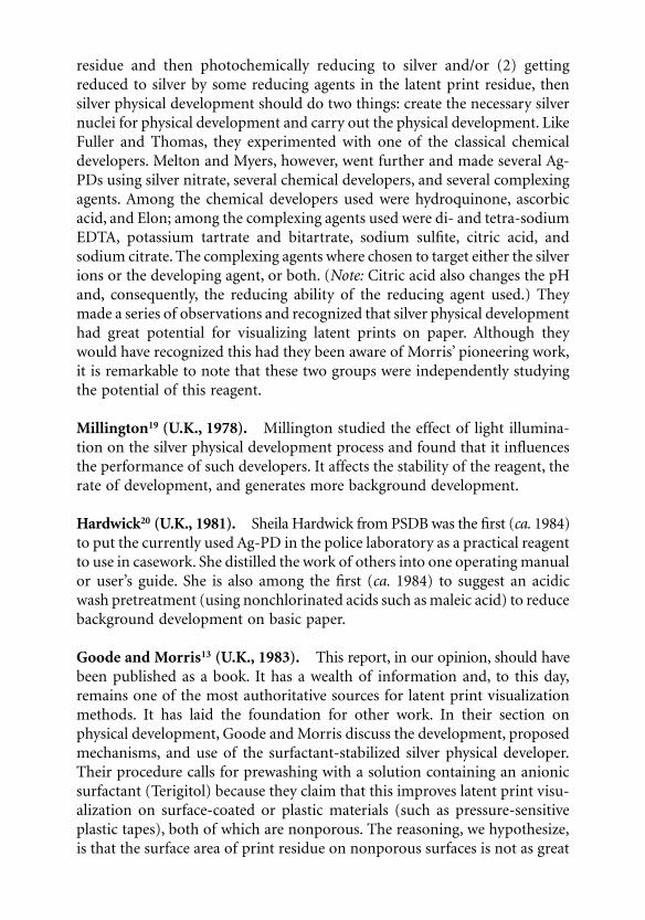
residue and then photochemically reducing to silver and/or (2) gettingreduced to silver by some reducing agents in the latent print residue, thensilver physical development should do two things: create the necessary silvernuclei for physical development and carry out the physical development. LikeFuller and Thomas, they experimented with one of the classical chemicaldevelopers. Melton and Myers, however, went further and made several Ag-PDs using silver nitrate, several chemical developers, and several complexingagents. Among the chemical developers used were hydroquinone, ascorbicacid, and Elon; among the complexing agents used were di- and tetra-sodiumEDTA, potassium tartrate and bitartrate, sodium sulfite, citric acid, andsodium citrate. The complexing agents where chosen to target either the silverions or the developing agent, or both. (
Note:
Citric acid also changes the pHand, consequently, the reducing ability of the reducing agent used.) Theymade a series of observations and recognized that silver physical developmenthad great potential for visualizing latent prints on paper. Although theywould have recognized this had they been aware of Morris’ pioneering work,it is remarkable to note that these two groups were independently studyingthe potential of this reagent.
Millington
19
(U.K., 1978).
Millington studied the effect of light illumina-tion on the silver physical development process and found that it influencesthe performance of such developers. It affects the stability of the reagent, therate of development, and generates more background development.
Hardwick
20
(U.K., 1981).
Sheila Hardwick from PSDB was the first (
ca.
1984)to put the currently used Ag-PD in the police laboratory as a practical reagentto use in casework. She distilled the work of others into one operating manualor user’s guide. She is also among the first (
ca.
1984) to suggest an acidicwash pretreatment (using nonchlorinated acids such as maleic acid) to reducebackground development on basic paper.
Goode and Morris
13
(U.K., 1983).
This report, in our opinion, should havebeen published as a book. It has a wealth of information and, to this day,remains one of the most authoritative sources for latent print visualizationmethods. It has laid the foundation for other work. In their section onphysical development, Goode and Morris discuss the development, proposedmechanisms, and use of the surfactant-stabilized silver physical developer.Their procedure calls for prewashing with a solution containing an anionicsurfactant (Terigitol) because they claim that this improves latent print visu-alization on surface-coated or plastic materials (such as pressure-sensitiveplastic tapes), both of which are nonporous. The reasoning, we hypothesize,is that the surface area of print residue on nonporous surfaces is not as great
0923Ch07Frame Page 249 Monday, May 14, 2001 3:10 PM

as that of print residue on porous surfaces and thus an anionic surfactant isneeded to give the residue a negative ionic character. Basically, the surfactantmolecule’s neutral, long side chain penetrates the lipid portion of print residue,leaving the negative end exposed. The residue thus acquires a negative charge.It attracts positively charged micelles to it and provides better “surfactant strip-ping.” Apparently, its effectiveness in improving visualization was not that sig-nificant because the current procedure does not call for this step; it only callsfor two prewashes: the distilled water wash and the acidic wash (with a non-chlorinated acid) for basic paper. Furthermore, paper washed with a solutioncontaining an anionic surfactant would probably not yield any visible printswhen treated with a surfactant-free Ag-PD (see later discussion).
Mechanism of Silver Physical Development
Hereafter, we refer to the currently used silver physical developer as the UK-PD. Again, this is the one based on what Morris
15
called the Philips PhysicalDeveloper.
Electrochemical Considerations
1
The key chemical reaction in silver physical developer is the catalytic reduc-tion of silver ions by the reducing agent. For this case, where we use the UK-PD, the key reactions are
Ag
+
+ Fe
2+
Ag + Fe
3+
(7.1)
Fe
3+
+ H
3
Cit FeCit + 3H
+
(7.2)
Ag
+
+ Fe
2+
+ H
3
Cit Ag + FeCit + 3H
+
(7.3)
where H
3
Cit is the (triprotic) citric acid and Cit
3–
is the (trinegative) citrateion. Equation (7.1) is the reduction of the silver ions, Equation (7.2) is theformation of the ferric citrate complex. The reaction quotient Q obtainedfrom Equation (7.3) is
Q = [FeCit][H
+
]
3
/[Ag
+
][Fe
2+
][H
3
Cit] (7.4)
This shows the strong dependence of Q on [H
+
] and thus on pH. It showsthat the silver physical development process is highly pH dependent.
Having chosen the reversible ferrous/ferric redox couple for the reducingagent gives the advantage that the process [Equation (7.3)] is reversible andtherefore treatable as an equilibrium system. Because the process is electro-chemical (silver gets reduced to silver metal as ferrous ions get oxidized to
0923Ch07Frame Page 250 Monday, May 14, 2001 3:10 PM

ferric ions), it can be thought of as an electrochemical cell consisting of twovessels connected by a salt bridge. One vessel contains the silver solution andthe other vessel contains the redox solution. In this case, the driving force ofthe cell is the cell potential, E
cell.
It is also the driving force of the reaction.This driving force is obtained from the Nernst equation. At room temperature(25°C), this is given by:
E
cell
= E
ocell
– 59 log Q (millivolts, mV) (7.5)
where
E
ocell
= E
ored
+ E
oox
(7.6)
E
ored
is the standard reduction potential for e
–
+ Ag
+
Ag,
E
ored
= 799.6 mV (7.7)
E
oox
is the standard oxidation potential for Fe
2+
+ H
3
Cit FeCit + 3H
+
+ e
–
.
E
oox
= –794.6 mV (7.8)
Therefore,
E
ocell
= E
ored
+ E
oox
= 5.0 mV (7.9)
E
oox
is derived from the oxidation potential of Fe
2+
Fe
3+
+ e
–
(–771 mV)
and
the formation constant of Fe
3+
+ H
3
Cit FeCit + 3H
+
(K
formation
= 0.398).The driving force, E
cell
, of the process and the thermodynamic Gibb’s freeenergy, ∆G, are related by
∆G = – nFEcell (7.10)
where n is the number of electrons involved in the electrochemical reaction(n = 1 in our case), F is Faraday’s constant (96,487 coulombs/equivalent),Ecell is in volts (i.e., joules/coulomb), and ∆G is in joules. Consequently, apositive Ecell means a negative free energy and this means the process isthermodynamically feasible and can proceed. For the Philips physical devel-oper, the cell potential is Ecell = 90 mV. Using Equations 7.5 and 7.9, thiscorresponds to Q = 0.03625. The reaction proceeds until equilibrium isreached because at equilibrium, ∆G = 0 and thus Ecell = 0 and Q = Keq. At
0923Ch07Frame Page 251 Monday, May 14, 2001 3:10 PM

equilibrium, the potential to deposit silver completely ceases. Because Eocell =
59 log Keq, then Keq = 1.21.
Stability of a Silver Physical DeveloperBy carefully choosing the concentrations of the components, one can obtaina reaction quotient Q such that Ecell is small but still positive. This is whatone wants in designing a stabilized silver physical developer because it sup-presses the spontaneous formation of silver particles in solution.12 The othercomponent necessary for stabilizing the developer is the addition of a cationicsurfactant to keep any spontaneously formed silver particles from growing. Thespontaneously formed silver particles acquire a negative charge from the sur-rounding citrate ions by adsorption (see Figure 7.1). The cationic surfactant
Figure 7.1 Cationic surfactant molecules surrounding a negatively charged sil-ver colloidal particle in a staggered manner, forming a positively charged micelle.The silver colloidal particle is negatively charged due to adsorbed citrate ions(Cit3–).
+
++
+
+
+
+
+
+
+ +
+
+ +
+
+
+
++
+Ag
Cit3-
Cit3-
Cit3-
Cit3-
Cit3-Cit3- Cit3-
Cit3-Cit3-
Cit3-
Cit3-Cit3-
Cit3-Cit3-Cit3-
Cit3-
0923Ch07Frame Page 252 Monday, May 14, 2001 3:10 PM

surrounds these negatively charged particles, forming micelles. The surfac-tant molecules are long-chain alkyl compounds with a positive end (anR–NH3
+ group). They arrange themselves on the negatively charged silverparticle in a staggered way: one with the positive end pointing toward theparticle and an adjacent one with the positive end pointing outward (seeFigure 7.1).12 These micelles have two properties: they are positively charged(because the molecules arrange themselves in a staggered way) and they forma thick cover. Both of these prevent positive silver ions from approachingthem and thus prevent their growth. Saunders21 formulated a simplifiedphysical developer (SPD) that contains no surfactant. For it to have anystability, he had to significantly reduce the amount of AgNO3 (by 72%) andthe ferrous/ferric redox couple (by 25%). It performs well during its stableperiod (about 1 hr) and thus helps to understand the role of the colloidalsilver with or without using surfactants.
Silver Image FormationThe reduction of the silver ions to silver metal by the oxidizing agent occurson nucleation or catalytic sites. In photographic chemistry, where silver phys-ical developers were first applied, the catalytic nucleation sites are on thephoto-exposed silver bromide crystals of the photographic emulsion. The silverspecks and silver sulfide specks are the actual sites. For visualizing latent prints,there is one explanation for the silver physical development of latent prints thathave not been wetted and several hypotheses for those that have been wetted.1
• For the non-wetted (dry) residue, Morris15 contends that the sodiumchloride in the latent print residue triggers the physical development.The silver ions form an insoluble salt with the chloride ions and theresulting silver chloride gets photoreduced to silver with ambient light,thus creating the silver nucleation sites.
• For the wetted residues, a hypothesis being proposed here is that thesilver physical developer actually provides the nucleation sites as spon-taneously formed silver particles attach themselves electrostatically onthe latent print residue.
A Hypothesis for the Silver Physical Development of Latent Prints Residue
This chapter section expands on the hypothesis mentioned above thatrequires the Ag-PD to contain spontaneously formed silver particles. Cantu1
has discussed several proposed explanations for the silver physical develop-ment of latent prints as well as the reasons why such development occursbetter on porous than on nonporous surfaces. The most likely of the reasonsfor physical development is based on the work by Morris15 and the ideas of
0923Ch07Frame Page 253 Monday, May 14, 2001 3:10 PM

Saunders.22 Both workers recognized the importance of having negativelycharged silver colloid particles and a low pH in the Ag-PD solution. Both ofthese are present in the UK-PD. The colloidal particles are selectivelyadsorbed on the print residue (which is positively charged), become neutral-ized, and function as catalytic nucleation sites for silver physical development.
Charge of Latent Print ResidueThe reason the print residue is positively charged is that in an acidic envi-ronment, residue components containing amine groups (R–NH2) and car-bon-carbon double bonds (–C�C–) get protonated.23 Among thecompounds with carbon-carbon double bonds in the print residue are theunsaturated lipid components and among the amines are insoluble proteins,lipoproteins, and even water-soluble proteins and amino acids that gettrapped in the lipid matrix as the print dries and hardens by oxidation. Theprotonation reactions are
R–NH2 + H+ → R–NH3+ (7.11)
(7.12)
Note that another way of providing a positive charge to the residue is by thecomplexation of silver ions with the double bonds in alkenes:24
(7.13)
Formation of Nucleating Sites on Latent Print ResidueAs stated, the role of the cationic surfactant in the stabilized UK-PD is tosuppress the growth of the spontaneously formed and negatively chargedsilver particles. Without the surfactant, these particles grow uncontrollably;however, when the surfactant is used, they begin as negatively charged par-ticles and gradually grow and reverse their charge until they are fully encasedwith surfactant molecules (micelle formation). At this point they cease togrow and are positively charged. These negatively charged particles have anelectrostatic attraction toward the cationic surfactant molecules; however, inthe vicinity of the positively charged print residue, they are also attracted tothe residue. In the proximity of the residue, the attractive forces are compet-itive. For particles formed in the bulk solution, micelle formation is dominant
0923Ch07Frame Page 254 Monday, May 14, 2001 3:10 PM
and this leads to stability; but for particles formed near the residue, particleattachment is preferred. The attachment or binding process is not immediateand probably requires that the silver particle not grow significantly duringthe process (more on this below). The attachment process neutralizes theparticles and makes them catalytic nucleation sites for silver physical devel-opment. Another way of depositing negatively charged silver particles on thepositively charged residue is by the “surfactant stripping” process suggestedby Morris. This involves already-formed silver micelles in the vicinity of theprint residue and the process is probably slower because both the micelle andthe residue are positively charged.
Formation of Silver Physical Developer Particles on Latent Print Residue: Silver Image FormationOnce the print residue acquires the catalytic nucleation sites, silver physicaldevelopment occurs on these sites. The final particles that grow on these sitesare spherical, about 5 to 40 µm in diameter, and are made up of strands ofsilver (see Figure 7.2). The gray to black color of these particles is attributedto their size and configuration. The print image is made up of a denseaccumulation of these particles.
Substrates
Porous vs. Nonporous Surfaces
Silver physical developers visualize latent prints better if they are on porousor semiporous surfaces rather than on nonporous surfaces. On porous sur-faces, latent print residue enters into and spreads throughout the porousstructure. It thus has a greater surface area and is more exposed than on anonporous surface. Because of this, more nucleating sites are formed on suchresidue and silver physical development (silver particle deposition andgrowth) occurs sooner and to a greater extent. Another reason why Ag-PDs,whether (cationic) surfactant stabilized or not, do not visualize latent printson nonporous surfaces well is because newly formed, negatively charged silverparticles grow. With a cationic surfactant, they also grow but after a certainpoint their growth is reduced and their charge is reversed. That is, thesedevelopers cannot retain particles of a fixed size and concentration longenough for a sufficient number of them to adhere to the latent print residue.Although the use of colloidal gold to create nucleation sites for subsequentsilver physical development is discussed later, it is sufficient to say that treat-ment with negatively charged, fixed-size colloidal gold particles (at suffi-ciently low pH to create a positive residue) does bring about sufficient particle
0923Ch07Frame Page 255 Monday, May 14, 2001 3:10 PM

Figure 7.2 Scanning electron microscope (SEM) images of silver particlesadhered to paper fibers with print residue. (Images taken by Jim Young and GaryMong, Pacific Northwest National Laboratory, Richland, WA.)
0923Ch07Frame Page 256 Monday, May 14, 2001 3:10 PM
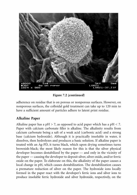
adherence on residue that is on porous or nonporous surfaces. However, onnonporous surfaces, the colloidal gold treatment can take up to 120 min tohave a sufficient amount of particles adhere to latent print residue.
Alkaline Paper
Alkaline paper has a pH > 7, as opposed to acid paper which has a pH < 7.Paper with calcium carbonate filler is alkaline. The alkalinity results fromcalcium carbonate being a salt of a weak acid (carbonic acid) and a strongbase (calcium hydroxide). Although it is practically insoluble in water, itdissolves, then hydrolyzes and produces a basic solution. If alkaline paper istreated with an Ag-PD, it turns black, which upon drying sometimes turnsbrownish-black; the most likely reason for this is that the silver physicaldeveloper becomes destabilized by the paper — and only in the vicinity ofthe paper — causing the developer to deposit silver, silver oxide, and/or ferricoxide on the paper. To elaborate on this, the alkalinity of the paper causes alocal change in pH, which causes destabilization. The destabilization causesa premature reduction of silver on the paper. The hydroxide ions locallyformed in the paper react with the developer’s ferric ions and silver ions toproduce insoluble ferric hydroxide and silver hydroxide, respectively, on the
Figure 7.2 (continued)
0923Ch07Frame Page 257 Monday, May 14, 2001 3:10 PM

paper and these convert to ferric oxide (Fe2O3 or rust) and silver oxide (brown-black Ag2O), respectively, upon drying. To avoid this, alkaline paper is neu-tralized by treating it with acid. The acid, however, must not be a chlorinatedacid (such as hydrochloric acid) because this introduces chloride ions, whichreact with silver to produce photosensitive silver chloride. Hardwick20 intro-duced the use of maleic acid. The concentration currently used is 2.5% (w/v).The Forensic Science Services (FSS) in London, U.K. uses a dilute solution(1%) of nitric acid.25,26 Others have used a 2.5% (w/v) malic acid solution,which is less costly than maleic acid. Household vinegar (5% acetic acid)works as well.27 The paper is treated until all bubbling ceases. The net reactionthat takes place is:
CaCO3 + 2H+ → Ca2+ + H2O + CO2 (gas) (7.14)
Preparation and Use of the Silver Physical Developer
Preparation
During preparation of the reagents associated with the silver physical devel-opment process, protective attire such as gloves, labcoat, protective eyewear,and mask should be worn. All containers used during the process should berinsed with distilled water prior to use.
The Acid Pretreatment ReagentAcids containing chlorine (e.g., hydrochloric acid) should not be used. A maleicacid solution is recommended, although as indicated above, dilute nitric oracetic acid also work. The maleic acid solution is made by thoroughly mixing25 g maleic acid into 1 l distilled water. This solution has an indefinite lifetime.
The Silver Physical Developer ReagentThe following formulation is for the UK-PD.1-4,13,15 It involves preparing threestock solutions and a working solution from these. The three stock solutionsare made as follows and in the order given:
1. Ferrous/ferric redox solution (with citric acid) stock solution:a. Measure 900 ml distilled water into a clean container.b. Thoroughly dissolve 30 g ferric nitrate (nonadyrate) into the dis-
tilled water.c. Thoroughly dissolve 80 g ferrous ammonium sulfate (hexahydrate)
into the above solution.
0923Ch07Frame Page 258 Monday, May 14, 2001 3:10 PM

d. Thoroughly dissolve 20 g citric acid (anhydrous) into the abovesolution.
e. The final solution should contain no undissolved crystals.2. Detergent solution
a. Measure 1 l distilled water into a clean container.b. Thoroughly dissolve 4 g n-dodecylamine acetate into the distilled
water.c. Thoroughly dissolve 4 g Synperonic-N into the above solution.
3. Silver nitrate solutiona. Measure 100 ml distilled water into a clean container.b. Thoroughly dissolve 20 g silver nitrate into the distilled water.c. Once the silver nitrate has totally dissolved, store the solution in an
amber glass bottle.
These stock solutions have an indefinite lifetime. The detergent solution mayhave a slightly cloudy appearance while the other two solutions should beclear. The working solution is made as follows and in the order given:
• Measure 900 ml redox solution into a clean container.• Add 40 ml detergent solution to the above solution and thoroughly
mix for approximately 5 min.• Add 50 ml silver nitrate solution to the above solution and thoroughly
mix for about 5 min.
The lifetime of the working solution is between 1 and 2 weeks. If a whiteprecipitate begins to form at the bottom of the container, a new solutionshould be made.
The Hypochlorite Post-Treatment ReagentThis reagent consists of a 1:1 (v/v) dilution of a household “chlorine” bleachwith water (50% dilution). These bleaches contain between 5 and 6% sodiumhypochlorite. Some use a 3:1 (v/v) water:bleach solution (25% dilution). Thissolution is stable indefinitely.
Procedure
In the procedure used by the U.S. Secret Service, one clean glass tray is usedfor all the treatments: water pre-wash, acid pre-wash, Ag-PD treatment, andhypochlorite post-wash. The solutions are disposed of properly (check localregulators) after each step. In some cases, the Ag-PD and maleic acid can bereused; however, this depends on the number of items processed and thenature of the contaminants on the items (e.g., reagents are not reused if theyprocessed items with biohazardous contaminants).
0923Ch07Frame Page 259 Monday, May 14, 2001 3:10 PM

Water and Acid PretreatmentsThe water pretreatment involves distilled water and is used to remove anydirt or debris that may be present on the evidence. It will also removeninhydrin-developed prints and stains as well as water-soluble inks. The acidpretreatment is absolutely necessary for basic papers because these usuallycontain (alkaline) calcium carbonate.
Silver Physical DevelopmentThis part of the process produces the visible prints, with their color rangingfrom gray to black. It should be performed in subdued light because silvernitrate can photo-reduce to silver and increase background development; italso reduces the activity of the developer. Prints begin to appear within 5 to10 min and processing should stop once sufficient contrast is achieved. Pro-cessing time ranges from 10 to 30 min.
Water and Hypochlorite Post-TreatmentsOnce the development is complete, the evidence is washed in running tapwater. Some recommend distilled water because tap water produces colloidalsize silver chloride particles that can become lodged in the paper and darkenwith time. We have found that using running water for about 5 min gets ridof these particles and chemicals from the Ag-PD (e.g., ferric, ferrous, andsilver ions). To enhance the darkness of the print and lighten the background(assuming the background is not high in silver physical development), Phil-lips et al.2 found that treating the evidence with a 50% solution of householdbleach (hypochlorite) for approximately 2 to 3 min gave this result. If thebackground is high in silver physical development, then it too will darken.The reaction occurring is the conversion of silver to silver oxide. After this,the evidence is washed again in running tap water and dried; drying can bedone with a photodryer. The evidence is photographed using film. The result-ing photograph can be digitally scanned for digital enhancement.
Examples
This chapter section provides casework examples of additional prints developedby the Ag-PD process, ninhydrin prints enhanced by the Ag-PD, Ag-PD printsenhanced by hypochlorite, and Ag-PD prints enhanced by digital processing.
Figure 7.3 compares a ninhydrin palm print on a letter and the same letterafter Ag-PD treatment. The Ag-PD process brought out an additional finger-print in the middle of the palm print. Figure 7.4 shows how the Ag-PD processenhanced a ninhydrin print on a forged United States Treasury check. Figure 7.5shows two things: the enhancement of a ninhydrin print on a counterfeit $20note and the removal by the Ag-PD treatment of the jet ink that printed thecounterfeit. Figure 7.6 shows an Ag-PD print before and after enhancement with
0923Ch07Frame Page 260 Monday, May 14, 2001 3:10 PM

hypochlorite bleach; and Figure 7.7 compares an Ag-PD print on a forged checkwith a patterned background and the same print after removing the backgrounddigitally using the Fast Fourier Transform (FFT) technique.
Figure 7.3 Comparison of a ninhydrin palm print on a letter before (top) andafter Ag-PD treatment (bottom). Additional fingerprint is revealed.
0923Ch07Frame Page 261 Monday, May 14, 2001 3:10 PM

The Multi-Metal Deposition Process
Background
Saunders28,29 introduced the multi-metal deposition (MMD) method forvisualizing latent prints on porous and nonporous surfaces. It is a modifica-tion of a biochemical technique used for staining proteins.30 The method
Figure 7.4 Comparison of a ninhydrin print on a forged United States Treasurycheck before (left) and after Ag-PD treatment (right). Ninhydrin print is enhanced.
Figure 7.5 Comparison of a ninhydrin print on a counterfeit $20 note before(left) and after Ag-PD treatment (right). Ninhydrin print is enhanced and ink(from inkjet printer) is removed.
0923Ch07Frame Page 262 Monday, May 14, 2001 3:10 PM

involves treating the test species (proteins in the biochemical case and latentprints in our case) with a colloidal gold solution (having a pH ~ 2.7) andthen with a weak solution of silver physical developer. The colloidal goldparticles are highly negatively charged and thus bind strongly with the targetspecies to form catalytic nucleating sites for silver physical development. Inthis technique, one speaks of silver amplifying the gold image.
Porous vs. Nonporous Surfaces
As indicated above, compared to the silver physical development method,which visualizes latent prints on porous rather than nonporous surfaces, theMMD method is able to visualize prints on both surfaces. Silver physicaldevelopers form and supply the colloidal particles that bind to the latentprint residue and these become the critical catalytic nucleating sites. Oncethese particles bind, they then grow in the development process. The MMDmethod, on the other hand, supplies already-formed colloidal particles thatdo not grow and can thus build up if given sufficient time. They grow onlyduring the silver physical development stage as silver builds up on them.Recall that for binding to occur, the silver or gold particles must reside onthe latent print residue for a sufficient amount of time without growingsignificantly. Thus, for nonporous surfaces (where the surface area of thelatent print residue is less expansive than on a porous surface), the MMDmethod must be given enough time to form a sufficient number of gold
Figure 7.6 Comparison of an Ag-PD print on a counterfeit $20 note before (left)and after hypochlorite bleach treatment (right). Ag-PD print darkens and back-ground lightens.
0923Ch07Frame Page 263 Monday, May 14, 2001 3:10 PM

nucleating sites so that good contrast is obtained with silver amplification.For porous surfaces, some investigators have found the MMD method resultsin excessive background development. This will occur if the unbound gold(i.e., gold particles that get occluded in the paper fibers) is not properlyremoved. This is why the washing procedure after the gold treatment is veryimportant.
Figure 7.7 Comparison of a ninhydrin print on a forged check with patternedbackground before (top left) and after Ag-PD treatment (top right) and aftersubtracting the patterned background using digital FFT methods (bottom).
0923Ch07Frame Page 264 Monday, May 14, 2001 3:10 PM

Formulation and Procedure29
Colloidal Gold Solution (Gold Sol)To prepare this solution, one needs a 10% (w/v) tetrachloroauric acid stocksolution, a 1% (w/v) trisodium citrate stock solution, a 0.5 M (9.6% w/v)citric acid stock solution, and Tween 20 (a non-ionic surfactant/detergent).The stock solutions must be made with distilled or deionized water (i.e., itmust be free of divalent ions, chlorine, and organic substances). These stocksolutions are stable indefinitely. To prepare 1 l of the colloidal gold workingsolution, add 1 ml of the 10% tetrachloroauric acid stock solution to 1 ldistilled water and bring to a boil. Rapidly add 10 ml of the 1% trisodiumcitrate stock solution and continue boiling gently for 10 min. The resultingcolloidal gold solution should be “port wine” in color. Turn off the heat andadd 5 ml Tween 20. Mix well and let cool to room temperature. When cool,add 10 ml of a 1% polyethylene glycol (molecular weight 10–15,000) andadjust the pH to 2.7 with 0.5 M citric acid (about 1 ml). Restore the volumeto 1 l with distilled water. Store in clean glass or plastic container in a refrig-erator. The gold sol is stable for at least 3 months. The gold colloidal particlesprepared in this way have an average size of about 30 nm. Margot andLennard3 use 15 ml trisodium citrate instead of 10 ml and exclude the poly-ethylene glycol.
Modified Silver Physical DeveloperTwo stock solutions are needed: a ferrous/ferric redox couple stock solutionand a 20% (w/v) silver nitrate solution. These stock solutions have an indef-inite shelf life when stored in clean glass bottles (dark glass for the silvernitrate solution). The redox stock solution is prepared by sequentially dis-solving into 1 l distilled water, 33 g ferric nitrate nonahyrate, 89 g ferrousammonium sulfate hexahydrate, 22 g citric acid, and 1 ml Tween 20. Theworking solution (the modified silver physical developer) is prepared byadding one part 20% silver nitrate solution to 99 parts of redox solution. Theworking solution should be prepared just prior to using because it is onlystable for about 15 min. Saunders later revised the formulation of the redoxstock solution to be about half as concentrated (16 g ferric salt, 43 g ferroussalt, 11 g citric acid, and 0.25 ml Tween 20). This provides the same resultsbut less quickly.
There are two points to be noted. First, a non-ionic surfactant is usedinstead of a more stabilizing cationic surfactant. Cationic surfactants preventthe silver from depositing around the bound gold particles. One reason forthis may be that the bound gold particles are not fully neutralized and thecationic surfactant surrounds them, forming a protective shield that keeps outsilver ions. Second, the amount of silver in the final developer is sufficiently low
0923Ch07Frame Page 265 Monday, May 14, 2001 3:10 PM

(0.2%) to not form silver oxide when used in alkaline paper; therefore, thereis no need to neutralize alkaline paper. This, in fact, is fortuitous becauseneutralization produces unwanted calcium ions (see below).
ProcedurePorous items should be prewashed several times with distilled water for 20to 30 min. A maleic acid pretreatment should be avoided for alkaline paperas this creates divalent calcium ions which destabilize the colloidal goldsolution. Nonporous items only need a single distilled water prewash of about10 min unless they are quite dirty (then several washes are necessary). Soakthe items in the colloidal gold solution for 30 to 120 min, but avoid over-development. Rinse the items in distilled water. For paper, rinse in severalchanges of distilled water for 15 min or more. Any gold colloids that aretrapped/occluded in the paper fibers must be removed to reduce backgroundinterference. Place the items in freshly prepared modified silver physicaldeveloper for 5 to 15 min. Silver amplification takes place almost immedi-ately; therefore, the items should be removed once good contrast betweenthe print and background is obtained. Finally, rinse in tap water to removeexcess developer, air dry, and photograph.
More Recent Formulations
Since Saunders’ work, most of the research performed on the MMD methodhas been by Dr. Bertrand Schnetz, who obtained his Ph.D. doing this workat the Institut de Police Scientifique et de Criminologie, University of Lau-sanne (Switzerland). In 1993,31 Schnetz experimented with replacing colloidalgold with protein-bound colloidal gold. This would bind to the latent printresidue and then this would be amplified with enzymes or stains formingcolored or fluorescent products. In 1997, he introduced the MMD II method.It recommends using siliconized glassware and colloidal gold particles witha particle size diameter of 14 nm (compared to 30 nm for the SaundersMMD). Recently, Schnetz published his most recent optimization of themethod.32
Enhancement Techniques
For silver physically developed prints that are weak or have a strong interferingbackground, one can use several enhancement techniques to improve thecontrast between the print and its background. The latter includes prints ondark or highly patterned surfaces. The enhancement techniques can begrouped into at least three classes: optical, physical, and chemical. Because adetailed description of these is already available,1 they are only summarized
0923Ch07Frame Page 266 Monday, May 14, 2001 3:10 PM

here. The optical or photoreproductive methods include simple photocopy-ing methods, standard film photographic methods, and digital image capturemethods.
Optical Methods
Photocopying MethodsPhotocopying methods are usually used to intensify a weak print. The effectis caused in part by the high contrast their images are meant to have, butalso by the fact that the spectral sensitivity of their “cameras” is differentfrom that of the human eye. In the latter case, if the spectral sensitivity reachesout into the near-infrared region, the contrast of certain background colorsweakens while that of the Ag-PD print does not. (“Ag-PD” is also used as anadjective to mean silver physically developed.)
Film Photographic MethodsThe versatility available to both film and digital photographic methodsincludes the choice of illuminating and viewing filters. In fact, use of laserillumination or illumination from an alternate light source is often used inphotographing evidence. With film photography, one also has a choice offilms of different sensitivities and of chemical development methods. Thus,photographic enhancement techniques involve a judicious choice of illumi-nating filters, viewing filters, film sensitivities, and processing methods toobtain the optimum contrast from a latent print image.
Digital Imaging MethodsAs with film photography, digital photography also uses diverse illuminatingand viewing filters. Similar to the human eye, photographic films, CCDcameras, optical scanners, and digital cameras have their own spectral sen-sitivities and this plays a critical role in the enhancement scheme. However,the greatest advantage of capturing a digital image is what can be done withthe image afterward. Image processing software that is designed to enhanceimage contrast includes Image-Pro (from Media Cybernetics) and Photoshop(from Adobe). Combining this enhancement capability with the choices offiltered illuminating/viewing conditions provides a powerful approach tooptimize contrast. For example, the image of an Ag-PD print on a coloredbackground viewed at two separate wavelengths can be manipulated toremove the background. This follows because the silver image has the samelevel of gray over a large spectral range but not the colored background. Also,well-defined patterned backgrounds can be removed by Fourier transformmethods. Images can be taken before and after development and comparedto remove background completely.
0923Ch07Frame Page 267 Monday, May 14, 2001 3:10 PM

X-Ray and Scanning Electron Microscopy Methods
Because silver is X-ray opaque, an Ag-PD print, which consists of a densecollection of silver particles (see Figure 7.2), should attenuate X-rays. Imagesof such prints can be obtained using transmission soft X-ray methods butthe print resolution is not as high as that of prints on images obtained usingother X-ray methods. One is scanning electron microscopy (SEM) equippedwith an X-ray fluorescence detector capable of doing elemental mapping,and the other is SEM capable of generating a backscatter electron image. Thelatter has been used in the U.K. to eliminate background printing from Ag-PD prints on dark printed surfaces. For this to work, the background (whichis normally printing) must not contain materials that cause silver physicaldevelopment! Certain inks contain lipids, colloidal metallic salts, and metal-lic-based dryers that can potentially promote silver physical development.
Chemical Methods
Because an extensive review of the chemical methods that have been devel-oped and used mostly in the U.K. to enhance Ag-PD prints is already avail-able,1 only a few are briefly discussed here. In any of these methods, a prewashstep must be performed to remove as much as possible the following sub-stances that may be on or in the paper: ferrous, ferric, silver and calciumions, ferric citrate, silver chloride particles (formed by washing with tap water),and silver particles (either from the solution or formed on/in the paper back-ground). Some of these may be difficult to remove, particularly the particlesthat are well attached to or occluded in the paper and ions that strongly adhereto cellulose fibers. Saunders33,34 recommends washing with distilled water thatcontains 1% (v/v) Tween 20, with at least three changes of water.
BleachingThese methods replace silver, which is gray to black in color due to itsconfiguration (see Figure 7.2), with a substance of lighter color. They areused to lighten Ag-PD prints that appear on dark surfaces. The methodsdeveloped by Morris and Wells35 are mostly borrowed from photographicchemistry and those of Saunders33,34 are based on silver chemistry. In bothcases, the conversion of silver is to a silver halide: silver bromide, silverchloride, or silver iodide. The conversion is usually performed under subduedlight because these substances are photosensitive and can revert back to silver(though in a different configuration). Morris and Wells35 cite two methodsfor forming the bromide: via oxidation with Br2/KBr and via oxidation withK3Fe(CN)6/KBr. Saunders prepares the silver chloride using a dilution of theferrous/ferric (citric acid) redox system and table salt. He forms the silveriodide using ferrous/ferric (citric acid) redox system and KI.
0923Ch07Frame Page 268 Monday, May 14, 2001 3:10 PM

IntensificationThese methods are used to enhance weak Ag-PD prints. There are at leastfour methods. The simplest of these is redipping in Ag-PD. This causesfurther development on existing silver particles contributing to their growth.It does not always add new particles to give a greater density of particles andalso it could increase the build-up of silver in the background. Goode andMorris13 proposed an intensification method that involves conversion of thesilver to silver sulfide (Ag2S), followed by silver physical development usinga nitrate/nitrite redox couple. Saunders suggests a rather novel intensificationmethod that uses the ferrous/ferric (citric acid) redox couple and a dilutesodium chloride (NaCl) solution. Its mechanism is not fully understood. Thefourth method involves sodium hypochlorite (NaOCl). A 25 to 50% solutionof household bleach, which is 5 to 6% NaOCl, lightens the background andintensifies the print. The most likely mechanism is that silver oxide (Ag2O)is formed. Except for the redipping method, all of these methods change thecomposition and surface characteristics of the original silver particle andboth changes contribute to its change and intensification in color.
Radioactive Sulfur Toning and AutoradiographyThis method was developed in the U.K.36 for removing interfering back-ground from Ag-PD prints. It involves converting the silver to radioactivesilver sulfide (Ag2
35S), where 35S is the β-emitting radioactive isotope of sulfurused, followed by autoradiography for imaging. As mentioned for the X-raymethods, if the background contains printing, the ink must not contain mate-rials that cause silver physical development to occur. If it does, any silver particleson the printing will also be converted to silver sulfide and be radio-imaged.
Current Research
Non-Silver Physical Development
There are at least two problems of economics with Ag-PDs: the silver isexpensive and about 20 to 50% of it is not used during the useful lifetime ofthe developer.26 The latter fact indicates that the developer is rather inefficientand that a good portion of silver is thrown away when the exhausted Ag-PDsolution is disposed. At present, there is no way to replenish used Ag-PD. In1969, Jonker et al.12 mentioned ways of making non-noble metal physicaldevelopers and later, in 1976,37 Molenaar et al. worked on optimizing thecopper physical developer. Dr. Kevin Kyle from the Special TechnologiesLaboratory, Santa Barbara, CA, assisted the United States Secret Service(USSS) in adapting the copper physical developer of Molenaar et al.37 forvisualizing latent prints on paper. Preliminary results show promise, but there
0923Ch07Frame Page 269 Monday, May 14, 2001 3:10 PM

is much to be done to optimize the system. This work was supported by theSpecial Technologies Program of the U.S. Department of Energy.
Diffusion Transfer
The USSS is investigating a method of transferring Ag-PD prints onto pho-tographic paper or film. The method is based on ideas of Dr. Edwin Landduring his development of the Polaroid transfer method.38 The actual processis referred to as diffusion transfer.39 To perform the transfer, one needs twoitems: receiver paper/film and an activator solution. The receiver paper/filmis a gelatin-coated material in which the gelatin contains activation sites forsilver physical development and the activator is a photographic developer(e.g., hydroquinone) plus hypo (sodium thiosulfate). The transfer materialscurrently being tested by the USSS are Kodak PMT matt receiver paper andKodak PMT activator. For transferring an Ag-PD print onto the paper/film,the silver image is first converted to a silver bromide image using any of thebromination methods. The brominated print is then placed on the receiverpaper/film and after this some activator solution is placed on the back of thepaper with the print. This is pressed with a rubber roller and then the paperwith the print is carefully lifted from the receiver paper/film. The receiverpaper/film, which now contains the print image without background, isallowed to dry. As mentioned, if the background is printing with ink thatcauses silver physical development, then this will also transfer. At present,this project is still under development.
Fluorescent Ag-PD
The idea of converting the silver image of an Ag-PD into a fluorescent imagehas enormous advantages; it strengthens the contrast of weak prints and itremoves background interference (i.e, if the background is not printed withink that promotes silver physical development). Thus far, there has been nosimple conversion of silver to a silver fluorescent compound. What has beendone is borrowed from photographic “toning” chemistry. In the mid-to-late1920s, motion picture photographic scientists created ways to change a silverimage into colored images.40 One that formed a red image involved arhodamine dye. At the time, the interest was in the red color product andnot its fluorescent properties. Under USSS guidance and with support fromthe Special Technologies Program of the U.S. Department of Energy, Dr.Kevin Kyle of the Special Technologies Laboratory, Santa Barbara, CA, mod-ified the photographic chemistry to apply it to an Ag-PD print. The resultingprint fluoresces in the furrow areas rather than on the ridges and there is nobackground fluorescence. The mechanism is rather detailed1 and is not dis-cussed here.
0923Ch07Frame Page 270 Monday, May 14, 2001 3:10 PM

Test of Effectiveness
Currently in our laboratory the effectiveness of an Ag-PD is crudely testedusing a test paper strip with a spot of gold chloride on it. The density of thegold chloride spot (gold chloride/area) is high because it is made with arelatively concentrated (20 mg/l) gold chloride solution. The Ag-PD reducesthe gold chloride to elemental gold and this catalyzes the deposition of silver.It only tests if the Ag-PD deposits silver on nucleation sites — not how wellor how fast. Barford et al.26 observed that the ferrous ion and silver ionconcentrations were the most critical factors affecting the effectiveness of anAg-PD. They found that the UK-PD performed best (with development time≤20 min) when the silver ion concentration does not fall below 50% of itsoriginal concentration and the ferrous ion concentration does not fall below60% of its original concentration. Seeing the importance of obtaining theseconcentrations, they determined the ferrous ion concentration using poten-tiometric titration and the silver ion concentration using a silver/sulfide solid-state electrode. Currently, Dr. Kyle is working on an alternate way of obtainingthe ferrous ion concentration.41 Also, Cantu is currently working with theInstitut de Police Scientifique et de Criminologie (University of Lausanne, Lau-sanne, Switzerland) in developing a test strip containing gold chloride spots ofequal size but of decreasing density. The test strip is placed into the Ag-PD attwo different times to estimate the rate and sensitivity of development.
Conclusion
Silver physical developer is a powerful reagent for recovering latent prints onporous surfaces that the amino acid visualizing reagents failed to develop. Itworks on the water-insoluble components of latent print residue and, conse-quently, works on water-soaked evidence. When it is used after a colloidal goldpretreatment, its working ability is extended to nonporous surfaces. A mecha-nism by which it works has been proposed. It is built on several observationsand offers avenues one can take to improve the current or create new physicaldevelopers. At present, the U.S. Secret Service uses about 1600 liters (423 gallons)of Ag-PD annually. It has increased the number of prints found on evidenceand brought about more convictions than when ninhydrin was used alone.
References
1. Cantu, A.A., On the composition of silver physical developers used to visu-alize latent prints on paper, Forensic Sci. Rev., 13, 29, 2001.
2. Phillips, C.E., Cole, D.O., and Jones, G.W., Physical developer: a practical andproductive latent print developer, J. Forensic Ident., 40, 135, 1990.
0923Ch07Frame Page 271 Monday, May 14, 2001 3:10 PM

3. Margot, P. and Lennard, C., Fingerprint Detection Techniques, 6th revisededition, Institut de Police Scientifique et de Criminologie, Universite de Lau-sanne, Lausanne, Switzerland, 1994.
4. Manual of Fingerprint Detection Techniques, Home Office, Police Scientificand Development Branch, London, 1992.
5. Kent, T., Hewlett, D.F., and Sears, V.G., A “Green” formulation for ninhydrin,81st Annu. Int. Assoc. for Identification Educational Conference and TrainingSeminar, Greensboro, NC, July 1997.
6. Walls, H.J. and Attridge, G.G., Basic Photo Science, Focal Press, London, 1977.
7. Larmoure, L., Introduction to Photographic Principles, Dover, New York, 1965.
8. Zakia, R. and Stroebel, L., Eds., The Focal Encyclopedia of Photography, 3rded., Focal Press, Boston, 1993.
9. James, T.H., Ed., The Theory of the Photographic Process, 4th ed., Macmillan,New York, 1977.
10. Bunting, R.K., The Chemistry of Photography, Photoglass Press, Normal, IL, 1982.
11. Feigl, F. and Anger, V., Spot Tests in Inorganic Analysis, Elsevier, Amsterdam,1972, 424.
12. Jonker, H., Molenaar, A., and Dippel, C.J., Physical development recordingsystem. III. Physical development, Photo. Sci. Eng., 13, 38, 1969.
13. Goode, G.C. and Morris, J.R., Latent Fingerprints: A Review of Their Origin,Composition, and Methods of Detection, Report 022/83, Atomic WeaponsResearch Establishment, Aldermaston, U.K., 1983.
14. Fuller, A.A. and Thomas, G.L., The Physical Development of FingerprintImages, Technical Memorandum 26/74, Home Office Scientific Research andDevelopment Branch, London, U.K., 1974.
15. Morris, J.R., The Detection of Latent Fingerprints on Wet Paper Samples,Memo No. 36, Atomic Weapons Research Establishment, Chemistry Division,Aldermaston, U.K., 1975.
16. Knowles, A.M., Jones, R.J., and Clark, L.S., Development of Latent Finger-prints on Patterned Papers and on Papers Subjected to Wetting, Tech. MemosNos. 6/76, 12/77, and 5/78; Home Office Police Scientific DevelopmentBranch, London, U.K., 1976–78.
17. Mughal, M.A., The Influence of Micelle Age on the Rate of Deposition of Silverfrom a Physical Developer Solution, Technical Memorandum 21/77 (reprintedas publication 60/80), Home Office Police Scientific Development Branch,London, U.K., 1977.
18. Melton, C.W. and Myers, W.C., Development of Improved and New Methodsfor the Detection and Recovery of Latent Fingerprints, Final Report to theFederal Bureau of Investigation (1977 Sept. 28), Battelle Columbus Labora-tories, Columbus, OH, 1977. Permission to cite this reference was providedby the Federal Bureau of Investigation.
0923Ch07Frame Page 272 Monday, May 14, 2001 3:10 PM

19. Millington, S., The Influence of Light on the Performance of a PhysicalDeveloper System, Technical Memorandum 13/78, Home Office Police Sci-entific Development Branch, London, U.K., 1978.
20. Hardwick, S.A., User Guide to Physical Developer — A Reagent for DetectingLatent Fingerprints; User Guide No. 14/81; Home Office Police ScientificDevelopment Branch, London, U.K., 1981.
21. Saunders, G., The Simplified Physical Developer, report presented at the ThirdInt. Conf. of Fingerprint Development Chemistry, U.S. Secret Service: Wash-ington, D.C., May, 19–21, 1993.
22. Saunders, G., personal communication, 1996.
23. Morrison, R.T. and Boyd, R.N., Organic Chemistry, Allyn and Bacon, Boston,1961, 114.
24. Cotton, F.A., Wilkinson, G., Murillo, C.A., and Bohmann, M., AdvancedInorganic Chemistry, 6th ed., John Wiley, New York, 1999, 1093.
25. Brennan, J., personal communication, 1999.
26. Barford, A.D., Brennan, J.S., Hooker, R.H., Price, C.J., Operational experi-ences in the use of physical developers for detecting latent marks (work inprogress).
27. Ramotowski, R., A comparison of different physical developer systems andacid pre-treatments and their effects on developing latent prints, J. ForensicIdent., 50, 363, 2000.
28. Saunders, G., Multimetal Deposition Method for Latent Fingerprint Devel-opment, Progress Report to the USSS, February 27, 1989. Also in theProceedings — 74th Annu. Educational Conf. Int. Assoc. Identification, Pensa-cola, FL, July 1989.
29. Saunders, G.C., Cantu A.A., Burns, C.D., Seifert, D.C., and Johnson, J.J.,Multimetal deposition technique for latent fingerprint visualization, unpub-lished manuscript, ca. 1990.
30. DeMey, J., Colloidal Gold Probes in Immunocytochemistry, in Immunohisto-chemistry, Practical Application in Pathology and Biology, Polak, J.M. and VanNoorden, S., Eds., John Wright and Sons, London, 1983, 82.
31. Schnetz, B., Latent fingerprint and colloidal gold: new reinforcement proce-dures, Abstract, International Association of Forensic Science, Dussoldorf,Germany, 1993.
32. Schnetz, B. and Margot, P., Latent fingermarks, colloidal gold and multimetaldeposition (MMD). Optimisation of the method, Forensic Sci. Int., in press.
33. Saunders, G., Fingerprint Chemistry I, Final Report to the U.S. Secret Service,Washington, D.C., Aug. 14, 1996.
34. Saunders, G., Fingerprint Chemistry II, Final Report to the U.S. Secret Ser-vice, Washington, D.C., Oct. 4, 1997.
0923Ch07Frame Page 273 Monday, May 14, 2001 3:10 PM

35. Morris, J.R. and Wells, J.M., An Examination of Intensification Proceduresfor Enhancing Silver Images produced by Fingerprint Reagents and Autora-diography; Memo No. 394, Atomic Weapons Research Establishment, Chem-istry Division, Aldermaston, U.K., July 1976.
36. Knowles, A.M., Lee, D., and Wilson, D., Development of Latent Fingerprintson Patterned Papers and Papers Subjected to Wetting. An Operational Trialof a New Reagent System — 35SPD, Technical Memorandum 12/77, HomeOffice Police Scientific Development Branch, London, U.K., 1977.
37. Molenaar, A., Heynen, G.H.C., and van den Meerakker, E.A.M., Physicaldevelopment by copper complexes using ferrous-ferric ions as a redox system,Photo. Sci. Eng., 20, 135, 1976.
38. Land, E.W., A new one-step photographic process, J. Opt. Soc. Am., 37, 61,1947.
39. Levenson, G.I.P., Diffusion transfer and monobaths, in The Theory of thePhotographic Process, 4th ed., James, T.H., Ed., Macmillan, New York, 1977,chap. 16.
40. Crabtree, J.I. and Ives, C.E., Dye toning with single solutions, Soc. Mot. Pict.Eng., 12, 967, 1928.
41. Kyle, K., personal communication, 1999.
0923Ch07Frame Page 274 Monday, May 14, 2001 3:10 PM

Automated Fingerprint Identification and Imaging Systems
ANIL JAIN
SHARATH PANKANTI
Contents
IntroductionEmerging ApplicationsSystem ArchitectureChallenges
Inconsistent ContactNon-uniform ContactIrreproducible ContactFeature Extraction ArtifactsSensing
Fingerprint SensingFingerprint RepresentationMinutiae Feature Extraction
Orientation EstimationSegmentationRidge DetectionMinutiae DetectionPost-processing
Fingerprint ClassificationFingerprint MatchingFingerprint EnhancementLarge-Scale Systems IssuesSystem EvaluationConclusions and Future Prospects AcknowledgmentsReferences
8
0923Ch08Frame Page 275 Monday, May 14, 2001 3:01 PM

Introduction
More than a century has passed since Alphonse Bertillon first conceived andthen industriously practiced the idea of using body measurements for solvingcrimes.
1
Just as his idea was gaining popularity, it faded into relative obscuritybecause of the far more significant and practical discovery of the uniquenessof the human fingerprint.* Soon after this discovery, many major law enforce-ment departments embraced the idea of first “booking” the fingerprints ofcriminals so that their records are readily available and later using leftoverfingerprint smudges (latents), so that the identity of criminals can be deter-mined. These agencies sponsored a rigorous study of fingerprints, developedscientific methods for visual matching of fingerprints and strong pro-grams/cultures for training fingerprint experts, and applied the art of finger-print identification for nailing down the perpetrators.
Despite the ingenious methods improvised to increase the efficiency ofthe manual method of fingerprint indexing and search, the ever-growingdemands on manual fingerprint identification quickly became overwhelm-ing. The manual method of fingerprint indexing resulted in a highly skeweddistribution of fingerprints into bins (types): most fingerprints fell into a fewbins and this resulted in search inefficiencies. Fingerprint training procedureswere time-intensive and slow. Further, demands imposed by painstakingattention needed to visually match the fingerprints of varied qualities, thetedium of monotonic nature of the work, and increasing workloads due toa higher demand on fingerprint identification services all prompted the lawenforcement agencies to initiate research into acquiring fingerprints throughelectronic media and automatic fingerprint identification based on the digitalrepresentation of the fingerprints. These efforts have led to the developmentof automatic/semi-automatic fingerprint identification systems over the pastfew decades. This chapter attempts to present the current state-of-the-art infingerprint sensing and identification technology.
The objective is to present a high-level overview of fingerprint sensingand matching technology so as to provide the reader with some insights intothe strengths and limitations of the automation in matching fingerprints.Because of space limitation, the focus is only on the core technology ratherthan the details of the commercial systems. The existing elaborate manualprotocols (e.g., What is a core? How are fingerprints indexed/filed in a manualsystem?) are not described for similar reasons. Readers are referred to Ref-erence 2 for an excellent exposition on these subject matters.
The remainder of this chapter is organized as follows: introduction ofemerging applications of automatic fingerprint matching and its implications;
* In 1983, the Home Ministry Office, U.K., accepted that no two individuals have the samefingerprints.
0923Ch08Frame Page 276 Monday, May 14, 2001 3:01 PM
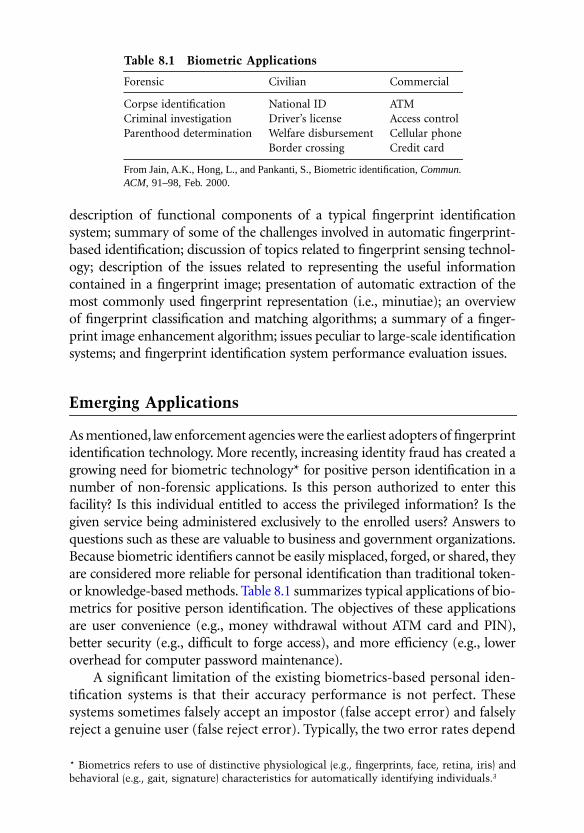
description of functional components of a typical fingerprint identificationsystem; summary of some of the challenges involved in automatic fingerprint-based identification; discussion of topics related to fingerprint sensing technol-ogy; description of the issues related to representing the useful informationcontained in a fingerprint image; presentation of automatic extraction of themost commonly used fingerprint representation (i.e., minutiae); an overviewof fingerprint classification and matching algorithms; a summary of a finger-print image enhancement algorithm; issues peculiar to large-scale identificationsystems; and fingerprint identification system performance evaluation issues.
Emerging Applications
As mentioned, law enforcement agencies were the earliest adopters of fingerprintidentification technology. More recently, increasing identity fraud has created agrowing need for biometric technology* for positive person identification in anumber of non-forensic applications. Is this person authorized to enter thisfacility? Is this individual entitled to access the privileged information? Is thegiven service being administered exclusively to the enrolled users? Answers toquestions such as these are valuable to business and government organizations.Because biometric identifiers cannot be easily misplaced, forged, or shared, theyare considered more reliable for personal identification than traditional token-or knowledge-based methods. Table 8.1 summarizes typical applications of bio-metrics for positive person identification. The objectives of these applicationsare user convenience (e.g., money withdrawal without ATM card and PIN),better security (e.g., difficult to forge access), and more efficiency (e.g., loweroverhead for computer password maintenance).
A significant limitation of the existing biometrics-based personal iden-tification systems is that their accuracy performance is not perfect. Thesesystems sometimes falsely accept an impostor (false accept error) and falselyreject a genuine user (false reject error). Typically, the two error rates depend
Table 8.1 Biometric Applications
Forensic Civilian Commercial
Corpse identification National ID ATMCriminal investigation Driver’s license Access controlParenthood determination Welfare disbursement Cellular phone
Border crossing Credit card
From Jain, A.K., Hong, L., and Pankanti, S., Biometric identification,
Commun.ACM
, 91–98, Feb. 2000.
* Biometrics refers to use of distinctive physiological (e.g., fingerprints, face, retina, iris) andbehavioral (e.g., gait, signature) characteristics for automatically identifying individuals.
3
0923Ch08Frame Page 277 Monday, May 14, 2001 3:01 PM

on the system operating point (called decision threshold) and their relation-ship is characterized by a receiver operating characteristic (ROC). Figure 8.1illustrates a hypothetical ROC and typical operating points for differentbiometric applications.
Tremendous success of fingerprint-based identification technology in lawenforcement applications, decreasing cost of the fingerprint sensing devices,increasing availability of inexpensive computing power, and growing identityfraud/theft have all ushered in an era of fingerprint-based person identifica-tion applications in commercial, civilian, and financial domains.
A typical law enforcement identification system serves a different purposethan those of the emerging biometric applications. Most of the financial andcommercial applications require identity verification (also known as authen-tication), which involves confirming/denying a claimed identity based onfingerprint information, given a claim to a specific identity (e.g., Joe Smith).
Figure 8.1
Receiver operating characteristics (ROC) curve of a system illustratesfalse reject rate (FRR) and false accept rate (FAR) of a matcher at all operatingpoints (threshold, T). Each point on an ROC defines FRR and FAR for a givenmatcher operating at a particular threshold. High security access applications areconcerned about break-ins, and hence operate the matcher at a point on ROCwith a small FAR. Forensic applications desire to catch a criminal even at theexpense of examining a large number of false accepts, and hence operate theirmatcher at a high FAR. Civilian applications attempt to operate their matchersat the operating points, with both low FRR and low FAR. (From Jain, A., Bolle,R., and Pankanti, S.,
Biometrics
:
Personal Identification in Networked Society,
Kluwer, Massachusetts, December, 1999.)
Equal Error Rate
Applications
High Security Access
Forensic Applications
Fals
e R
ejec
t Rat
e (F
RR
)
False Accept Rate (FAR)
ApplicationsCivilian
0923Ch08Frame Page 278 Monday, May 14, 2001 3:01 PM

That is, given a fingerprint known to have originated from, for example, JoeSmith’s left index finger and another print from a left index finger, the systemwill determine whether the second print, indeed, belongs to Joe Smith. Thelaw enforcement systems, on the other hand, primarily deal with recognition(also popularly referred to as
identification
, as in automatic fingerprint iden-tification system), which involves establishing the identity of the person basedon the fingerprint information. Given a fingerprint(s), possibly without anyknowledge of the finger position (i.e., left index), the system, by
searching
through the database of available fingerprints associated with the knownidentities, will determine whether the print is associated with an identity.*The task of identity verification is much easier than that of identity recogni-tion: the former involving just one comparison while the latter involvesmultiple comparisons with fingerprints in the database. Although some civil-ian applications involve identity recognition, the underlying design consid-erations are different (see Figure 8.1). Despite these differences in thefunctionalities among different fingerprint identification applicationdomains, all the fingerprint based systems rely on the distinctive individualinformation in fingerprints — the fingerprint expertise which has primarilyresided within law enforcement agencies for more than a century. Further,the authors believe that law enforcement agencies will eventually also beclosely involved in studying the civilian/commercial/financial fingerprint(and more generally biometric) applications as well.
For any biometric measurement to be incorporated into a positive personidentification system, it is necessary that such measurements be acceptableto society. Despite the
criminal
stigma associated with fingerprints, a recentCNN poll found that fingerprints rate high in social acceptability.
4
Whileacceptability is a complex (and mutable) phenomenon depending on con-founding factors including individual/institutional trust, religious and per-sonal beliefs/values, and culture, two system issues influence acceptability:system security
5
and individual privacy.
6,7
The security issues ensure that theintruders will neither be able to access the individual information/measure-ments (e.g., obtain fingerprint information) nor be able to pose as otherindividuals by electronically interjecting stale and fraudulently obtained bio-metrics measurements (e.g., surreptitiously lifted fingerprints from surfacestouched by the individuals) into the system. It is desirable that a personalidentification system uses the biometric measurements exclusively for thepurposes for which they were acquired. For example, it may be possible toglean information about the medical conditions of individuals from their
* The term “identification” is used in this chapter either to refer to the general problemof identifying individuals (identification/recognition and authentication/verification) or torefer to the specific problem of identifying (recognizing) an individual from a databasewhich involves one to many searches. We rely on the context to disambiguate the reference.
0923Ch08Frame Page 279 Monday, May 14, 2001 3:01 PM

biometric measurements. Second, people are concerned about
linkages
:unauthorized usage of biometric measurements across different identifica-tion systems (e.g., criminal and civilian fingerprint identification systems) tolink the identities of people and to gather/track individual information thatmay otherwise be unavailable. It is necessary to enforce systemwide mecha-nisms to ensure the usage of the biometric measurement for its proscribedintent. As novel applications of fingerprints (and other biometric identifiers)become more widespread, law enforcement agencies will be increasinglyinvolved in resolving the frauds involving repudiation (e.g., users denying havingaccessed the system), coercion (e.g., users claiming to have been forced into thesystem), contamination (e.g., erroneous acquisition of biometrics identifier notassociated with the intended user), and circumvention (e.g., unauthorized user
Figure 8.2
Functional block diagram of an “automatic” fingerprint identifica-tion system. The dotted lines illustrate alternative paths. Some of the functionalblocks (e.g., indexing) can be performed either by an expert or a computer. Thefeature editing and match verification tasks are performed by an expert. Typically,a fingerprint matcher passes a ranked list of 10 to 100 fingerprints for the matchverification stage; a fingerprint expert browses the
original
fingerprint images (asopposed to their representations) to confirm/reject a candidate match.
FingerprintEnhancement
IndexingFingerprint
FeatureExtraction
FingerprintMatching
Editing
MatchVerification
Feature
FingerprintAcquisition Estimation
Quality
0923Ch08Frame Page 280 Monday, May 14, 2001 3:01 PM

illegitimately gaining access to the system). Consequently, agencies may notonly be required to pass judgments about the identities related to biometricidentifiers but also about the integrity of the systems and the validity of thebiometric measurements.
System Architecture
A fingerprint identification system is an automatic pattern recognition systemthat consists of three fundamental stages: (1) data acquisition: the fingerprintto be recognized is sensed; (2) feature extraction: a machine representation(pattern) is extracted from the sensed image; and (3) decision-making: therepresentations derived from the sensed image are compared with a repre-sentation stored in the system. The comparison typically yields a matchingscore quantifying the similarity between the two representations. If the scoreis higher than a threshold (determined by the system operating point [seeFigure 8.1]), the representations are determined to have originated from thesame finger(s). In an identification system, multiple comparisons may beneeded. Often, the stored representations in the database are partitioned intobins, based either on information extrinsic to the sensed input measurements(e.g., sex and age of the individual) or on information intrinsic to the sensedimage (e.g., fingerprint class or type [see “Fingerprint Classification” sec-tion]). As a result, the input fingerprint need not be searched in the entiredatabase, but only in the particular bin(s) of interest.
Different systems may use different numbers of available fingerprints(multiple impressions of a single finger or single impressions of multiplefingers) for person identification. The feature extraction stage may involvemanual override and editing by experts. Image enhancement may be usedfor poor-quality images (see “Fingerprint Enhancement” section).
Challenges
While significant progress has been made in automatic fingerprint identifi-cation, there are still a number of research issues that need to be addressedto improve system accuracy. Most of the shortcomings in the accuracy of anautomatic fingerprint identification system can be attributed to the acquisi-tion process:
Inconsistent Contact
The act of sensing distorts the fingerprint. Determined by the pressure andcontact of the finger on the glass platen, the three-dimensional shape of the
0923Ch08Frame Page 281 Monday, May 14, 2001 3:01 PM

finger gets mapped onto the two-dimensional surface of the glass platen.Because the finger is not a rigid object and because the process of projectingthe finger surface onto the image acquisition surface is not precisely con-trolled, different impressions of a finger are related to each other by varioustransformations. The most problematic of these projections appears to be
elastic
distortions of the friction skin of the finger that displaces differentportions of the finger (ever so slightly) by different magnitudes and in dif-ferent directions (see Figure 8.14).
Non-uniform Contact
The ridge structure of a finger would be completely captured if ridges belong-ing to the part of the finger being imaged are in complete physical/opticalcontact with the image acquisition surface and the valleys do not make anycontact with the image acquisition surface (see Figure 8.6). However, thedryness of the skin, shallow/worn-out ridges (due to aging/genetics), skin dis-ease, sweat, dirt, and humidity in the air all confound the situation, resultingin a non-ideal contact situation. In the case of inked fingerprints, an additionalfactor may include inappropriate inking of the finger; this results in “noisy,” low-contrast images, which leads to either spurious or missing minutiae.
Irreproducible Contact
Manual work, accidents, etc. inflict injuries to the finger, thereby changingthe ridge structure of the finger either permanently or semi-permanently.Further, each impression of a finger may possibly depict a different portionof its surface. This may introduce additional spurious fingerprint features.
Feature Extraction Artifacts
The feature extraction algorithm (see, for example, “Minutiae Feature Extrac-tion” section) is imperfect and introduces measurement errors. Various imageprocessing operations might introduce inconsistent biases to perturb thelocation and orientation estimates of the reported fingerprint structures fromtheir gray-scale counterparts.
Sensing
The act of sensing itself adds noise to the image. For example, in the live-scan fingerprint acquisition method, residues from the previous fingerprintcapture may be left behind. A typical imaging system geometrically distortsthe image of the object being sensed due to imperfect imaging conditions.In the Frustrated Total Internal Reflection sensing scheme (see “FingerprintSensing” section), for example, there may be a geometric distortion becausethe image plane is not parallel to the glass platen.
0923Ch08Frame Page 282 Monday, May 14, 2001 3:01 PM

Apart from the fingerprint acquisition and feature extraction issues, thereare three major additional challenges.
10
Although a number of automaticfingerprint classification methods (see “Fingerprint Classification” section)have been proposed and some of them are used in operational systems,fingerprint classification still remains one of the most difficult problems forboth humans and machines. Currently, the fingerprint classification frame-work is mainly intended for human experts; this may not be optimal for anautomatic system.
In designing any automatic pattern recognition system, an importantissue is the performance assessment of the system: how to evaluate the per-formance of a given system or how to verify that a deployed system satisfiescertain performance specifications. Unfortunately, the performance evalua-tion problem is far from well established.
In the absence of a good fingerprint compression scheme, storing hun-dreds of millions of fingerprints is too expensive. The wavelet-based method,Wavelet/Scalar Quantization (WSQ), which has been proposed as the stan-dard for fingerprint compression, can compress a fingerprint image by afactor of 10 to 25 (see Figure 8.3).
11,12
An algorithm that can reach an evenhigher compression ratio is an important research topic.
Fingerprint Sensing
Depending on whether the acquisition process is offline or online, a finger-print may be either (1) an inked fingerprint, (2) a latent fingerprint, or (3)a live-scan fingerprint.
The term inked fingerprint is used to indicate that the fingerprint imageis obtained from an impression of the finger on an intermediate mediumsuch as paper. An example of a rolled inked fingerprint is shown inFigure 8.4a. Typically, the first step in capturing a rolled impression of afingerprint is to place a few dabs of ink on a slab and roll it out smoothlywith a roller until the slab is covered with a thin, even layer of ink. The fingeris then rolled from one side of the nail to the other side over the inked slab,which inks the ridge patterns on top of the finer completely. After that, thefinger is rolled on a piece of white paper so that the inked impression of theridge pattern of the finger appears on the white paper. Rolled inked finger-prints impressed on paper can be electronically scanned into digital rolledfingerprints using optical scanners or video cameras. The rolled acquisitionmethod has remained a standard technique for fingerprint acquisition for morethan a 100 years.
2,16
Rolled inked fingerprints tend to have a large area of validridges and furrows, but have large deformations due to the inherent nature ofthe rolled acquisition process. Acquisition of rolled fingerprints is cumbersome,slow, and requires practice and skill. In the context of an automatic personal
0923Ch08Frame Page 283 Monday, May 14, 2001 3:01 PM

identification system, it is both infeasible and socially unacceptable to use therolled inked method to acquire fingerprints in the operational phase, althoughit may be feasible to use the rolled inked method in the enrollment phase.*
Another method of acquiring an inked impression is called a dab (seeFigure 8.4b). In this method, the inked finger is simply impressed on the paperwithout rolling it from nail to nail. Obviously, the fingerprint dab images covera smaller fingerprint pattern area, but there is a smaller distortion in the print.
Figure 8.3
Fingerprint compression: (a) an uncompressed fingerprint image; (b)portion of image in (a) compressed using a generic image compression algorithm,JPEG
13
; and (c) portion of image in (a) compressed using Wavelet/Scalar Quanti-zation (WSQ), a compression algorithm specifically developed for compressingimages. Both JPEG and WSQ use a compression ratio of 12.9; JPEG typicallyintroduces blocky artifacts and obliterates detailed information. See Reference14 for more detailed imagery.
* For example, Master Card relies on inked impressions for enrollment.
(a) (b)
(c)
0923Ch08Frame Page 284 Wednesday, May 16, 2001 12:04 PM

Figure 8.4
Comparison of different fingerprint impressions: (a) a rolled inkedfingerprint (from NIST 4 database); (b) an inked dab fingerprint (from NIST 4database); (c) live-scan (dab) fingerprint (captured with a scanner manufacturedby Digital Biometrics); (d) a latent fingerprint; (e) fingerprint captured using asolid-state sensor. (From Jain, A.K. and Pankanti, S.,
Handbook for Image andVideo Processing
, Bovik, A., Ed., ©Academic Press, April 2000.)
(a) (b)
(c) (d)
(e)
0923Ch08Frame Page 285 Monday, May 14, 2001 3:01 PM

In forensics, a special kind of inked fingerprints, called latent fingerprints,is of great interest. Constant perspiration exudation of sweat pores on fin-gerprint ridges and intermittent contact of fingers with other parts of thehuman body and various objects leave a film of moisture and/or grease onthe surface of fingers. In touching an object (e.g., a glass), the film of moistureand/or grease may be transferred to the object and leave an impression ofthe ridges thereon. This type of fingerprint is called a latent fingerprint.Latent fingerprints are very important in forensics. Actually, a major task inforensic fingerprinting application is searching and reliably recording latentfingerprints, which is dealt with elsewhere in this book. An example of alatent fingerprint is shown in Figure 8.4d.
The live-scan fingerprint is a collective term for a fingerprint imageobtained directly from the finger without the intermediate step of getting animpression on paper. A live-scan fingerprint is usually obtained using thedab-method, in which a finger is impressed on the acquisition surface of adevice without rolling.* A number of sensing mechanisms can be used tosense the ridge and furrows of the finger impressions, including (1) opticalfrustrated total internal reflection (FTIR),
17-19
(2) ultrasonic reflection,
20-22
(3) optical total internal reflection of holograms,
23-25
(4) thermal sensing ofthe temperature differential (across the ridges and valleys),
26,27
(5) sensing ofdifferential capacitance (across the ridges and valleys),
28-31
and (6) non-con-tact 2-D or non-contact 3-D scanning.
32,33
Scanners based on these physicalprocesses can be used to acquire the fingerprint impressions directly andthese acquisition methods eliminate the intermediate digitization process ofinked impressions and enable the design of online verification systems.Depending on the clarity of ridge structures of scanned fingers and acquisi-tion conditions, live-scan fingerprints vary in quality. Because of the onlinenature of this acquisition method, it is possible to directly observe the printbeing acquired; such a visual feedback turns out to be the single most impor-tant factor in controlling the quality of acquired fingerprints.
The most popular technology to obtain a live-scan fingerprint image isbased on the optical frustrated total internal reflection (FTIR) concept.
17
When a finger is placed on one side of a glass platen (prism), ridges of thefinger are in contact with the platen, while the valleys of the finger are notin contact with the platen. The remainder of the imaging system essentiallyconsists of an assembly of an LED light source and a CCD camera placed onthe other side of the glass platen. The laser light source illuminates the glassat a certain angle and the camera is placed such that it can capture the laserlight reflected from the glass. The light that is incident on the plate at the
* It is also possible to capture a rolled live-scan fingerprint. Some vendors use elaboratesoftware and/or scanner arrangements to capture rolled fingerprint live-scan images fromone or more live-scan dabs.
0923Ch08Frame Page 286 Monday, May 14, 2001 3:01 PM

glass surface touched by the ridges is randomly scattered, while the lightincident at the glass surface corresponding to valleys suffers total internalreflection, resulting in a corresponding fingerprint image on the imagingplane of the CCD. An example of a live-scan fingerprint is shown inFigure 8.4c. Figure 8.5 shows an FTIR fingerprint scanner and Figure 8.6depicts the sensing mechanism. Typically, an optical live-scan fingerprintscanner images span an area that is approximately 0.75 in.
2
. There are vendorsthat supply optical scanners which are also capable of imaging very largeareas of friction skin and facilitate ten-print or palmprint/soleprint scanning(see, for example, References 32 and 35).
The other live-scan modalities of fingerprint acquisition strive to(1) reduce the size/price of the optical scanning system, (2) improve thequality/resolution of the prints, and/or (3) improve the geometric/photo-metric/elastic distortion characteristics involved in the image capture. Forexample, by scanning the internal layers of friction skin (as opposed toscanning the superficial surface layers of the friction skin), an ultrasoundmethod of fingerprint imaging is believed to be capable of acquiring a veryclear fingerprint image even if the impressed finger does not apparently haveclear ridge structures. Imaging in a typical FTIR optical scanner suffers fromgeometric distortion because the fingerprint surface (platen) is not parallelto the imaging surface. Hologram-based live scans avoid this problem andhence the resulting fingerprint images are believed to have better spatialfidelity. Further, the edge-lit holograms
23
avoid bulky illumination opticsand are thus compact. Some hologram-based scanners have demonstrated
Figure 8.5
FTIR fingerprint scanner manufactured by Digital Biometrics. (FromDigital Biometrics, Digital Biometrics Homepage, http://www.digitalbiomet-rics.com/. With permission.)
0923Ch08Frame Page 287 Monday, May 14, 2001 3:01 PM

Figure 8.6
Optical fingerprint sensing. (a) Imaging geometry consists of a lasersource (L) illuminating a finger resting on a glass platen/prism (P) and an imagingsurface (C). (b) Frustrated total internal reflection: the ray A incident at theridge/glass interface scatters while the ray B falling at the valley/glass interfacesuffers total internal reflection and the reflected rays are collected at the imagingsurface.
L
P
C
(a)
Finger Friction Surface
PV
A B
R
C
(b)
0923Ch08Frame Page 288 Monday, May 14, 2001 3:01 PM

1000 dpi resolution
36
in laboratory settings. Thomson CSF manufactures a“sweep”-based fingerprint scanner based on thermal sensing; this scheme claimsto have significantly better reliability in harsh environmental conditions and alarge imaging area. The contact-less scanners permit imaging without contactand hence eliminate the problems related to elastic distortion in the finger-prints caused by contact with the presentation surface. Optical scanners aretoo large to be readily integrated in a number of applications such as laptopsecurity, cellular phone security, and notebook security. Recently, a numberof different types of compact solid-state fingerprint chips have become avail-able. These solid-state chips can be manufactured at very low cost if madein large quantities. Figure 8.7 shows two commercially available solid-statefingerprint chips.
Live-scan fingerprinting is an emerging technology and it is too early toassess its strengths based on the existing commercial products. At thismoment, with respect to imaging area, gray-scale resolution, and spatialresolution, (rolled) inked fingerprints appear to be superior to the opticallive-scans; optical FTIR live-scans are superior to solid-state fingerprintssensors. The forensic community has extensively evaluated the quality of live-scan fingerprints and expressed concerns about quality of fingerprints acquiredusing live-scan fingerprint sensors. In its quest to establish minimum require-ments for fingerprint acquisition for criminal applications, various U.S. Gov-ernment agencies have compiled compliance specifications for the optical live-scan fingerprints (see, for example, image quality specifications (IQS).
38,39
Figure 8.7
Solid-state fingerprint chips. (a) Differential capacitance fingerprintchip manufactured by Veridicom. (From
Veridicom. Veridicom Homepage.http://www.veridicom.com/.
) (b) A capacitance-based fingerprint imaging mousemade by Siemens. (
Siemens. The ID Mouse from Siemens. http://www.fingertip.de/.
)
(a) (b)
0923Ch08Frame Page 289 Monday, May 14, 2001 3:01 PM

Fingerprint Representation
A fingerprint is a smoothly flowing pattern of alternating valleys and ridges,the ridges and valleys being parallel in most regions. Several permanent andsemi-permanent features such as scars, cuts, bruises, cracks, and calluses arealso present in a fingerprint.
What information is available in fingerprints to enable sound judgmentabout whether two prints have originated from the same finger or fromtwo distinct fingers? To reliably establish whether two prints came fromthe same finger or different fingers, it is necessary to capture some
invariant
representation (features) of the fingerprints: the features which over a life-time will continue to remain relatively unaltered irrespective of the cuts andbruises, the orientation of the finger placement with respect to the mediumof the capture, occlusion of a small part of the finger, the imaging technologyused to acquire the fingerprint from the finger, or the elastic distortion ofthe finger during the acquisition of the print.
Several representations have been used to assess fingerprint similarity.Fingerprint representations can be broadly categorized into two types: globaland local. A global representation is an overall attribute of the finger and asingle representation is valid for the entire fingerprint and is typically deter-mined by an examination of the entire finger. A local representation consists ofseveral components, each component typically derived from a spatiallyrestricted region of the fingerprint. Typically, global representations are used forfingerprint indexing and local representations are used for fingerprint matching.
One of the significant global features used for fingerprints is its class ortype. The overall fingerprint pattern is typically categorized into a smallnumber of classes. Several fingerprint classification schema exist and, asmentioned earlier, we will avoid delving into the details of the classificationsschema adopted by different automatic identification systems. A typical fin-gerprint classification scheme categorizes the prints into the following sixmajor classes: whorl, right loop, left loop, arch, twin loop, and tented arch(see Figure 8.8).* Sometimes, a synthetic category called
scars
is included toclassify fingerprints mutilated with scars, thus obscuring the possibility ofaccurately determining its true class.
Fingers can also be distinguished based on features such as ridge thick-ness, ridge separation, or ridge depths. Some examples of global representa-tion include information about locations of critical points (e.g., core anddelta) in a fingerprint. Core-delta ridge count feature, sometimes simplyreferred to as the ridge count, measures the number of ridges between core
* A typical AFIS may use the following eight classes: (1) whorl, (2) radial loop, (3) ulnarloop, (4) double loop, (5) arch, (6) tented arch, (7) accidental, and (8) central pocket loop.
0923Ch08Frame Page 290 Monday, May 14, 2001 3:01 PM

and delta points (see Figure 8.8) on a finger.* All these features measure anoverall property of a finger and these similarities are referred to as global orgeneric features.
Major representations of the local information in fingerprints are basedon finger ridges, pores on the ridges, or salient features derived from theridges. Sometimes, the entire fingerprint itself (or some condensed form ofit) is used as the fingerprint representation.
40,41
The most widely used localfeatures are based on minute details (minutiae) of the ridges (Figures 8.9 and8.10). The pattern of the minute details of a fingerprint forms a valid repre-sentation of the fingerprint. This representation is compact and captures asignificant component of individual information in fingerprints; comparedto other representations, minutiae extraction is relatively more robust to varioussources of fingerprint degradation. Most types of minute details in fingerprintimages are not stable and cannot be reliably identified by automatic imageprocessing methods. Therefore, in automatic fingerprint matching, only thetwo most prominent types of minute details are used for their stability androbustness: (1) ridge ending and (2) ridge bifurcation. In addition, becausevarious data acquisition conditions such as impression pressure can easilychange one type of minutiae into the other, typical minutiae-based repre-sentations do not make any distinction between these two types of featuresand are collectively referred to as minutiae. The simplest of the minutiae-based representations constitute a list of points defined by their spatial coor-dinates with respect to a fixed image-centric coordinate system. Typically,however, these minimal minutiae-based representations are further enhancedby tagging each minutiae (or each combination of minutiae subset, e.g., pairs,triplets) with additional features. For example, each minutiae could be asso-ciated with the orientation of the ridge at that minutiae; or each pair of theminutiae could be associated with the ridge count, which is the number ofridges visited during the linear traversal between the two minutiae. TheANSI-NIST standard representation of a fingerprint is predominantly basedon minutiae and includes one or more global attributes such as orientationof the finger, locations or core or delta,** and fingerprint class. Typically, ina live-scan fingerprint image of good quality, there are approximately 40 to60 minutiae (in a typical 512
×
512 image).Another local fingerprint feature is sweat pore information. The location
and densities of the minute sweat pores have been found to contain infor-mation helpful in distinguishing individuals.
36
* Some categories of fingerprints do not intrinsically have any core or delta. In such cases,an automatic system may in some consistent way define other landmark features offingerprints in lieu of core-delta ridge count, core, and/or delta.** Core and delta are the two distinctive global structures in a fingerprint.
2
See Figure 8.8c.
0923Ch08Frame Page 291 Monday, May 14, 2001 3:01 PM

The guidelines for (visual) matching of fingerprints are quite elaborate.A fingerprint expert often relies on subtle and complex reasoning to arguewhether two prints originated from a single finger or two distinct fingers.For example, an expert can visually localize several rich features of a finger-print with remarkable accuracy. These features include the locations of core,delta, islands, dots, short ridges, ridge endings, ridge bifurcations, and numerical
Figure 8.8
A fingerprint classification schema involving six categories: (a) arch,(b) tented arch, (c) right loop, (d) left loop, (e) whorl, and (f) twin loop. Criticalpoints in a fingerprint, called core and delta, are marked as squares and triangles,respectively. An arch does not have a delta or a core. One of the two deltas in(e) and both deltas in (f) are not imaged. A sample minutiae ridge ending (o) andridge bifurcation (
×
) are illustrated in (e). Each image is 512
×
512 with 256 graylevels and is scanned at 512 dpi resolution. (From Jain, A., Hong, L., Pankanti,S., and Bolle, R., On-line identity-authentication system using fingerprints.
Proc.IEEE (Special Issue on Automated Biometrics)
, 85(9), 1365–1388, ©IEEE, Sep-tember 1997.)
(a) (b)
(c) (d)
0923Ch08Frame Page 292 Monday, May 14, 2001 3:01 PM

values of orientation of the ridges, and number of ridges between two features(ridge counts). An expert can reliably use judgments about scars, complex visualtextures, sweat pores, and ridge thickness to rule out false matches. It is not anexaggeration to state that research in automatic fingerprint identification hasbeen mostly an exercise in imitating the performance of a human fingerprint
Figure 8.8 (continued)
Figure 8.9
Schematic representation of a ridge ending (E) and a ridge bifurca-tion/branching (B). A minutiae is typically quantified by its (
x
,
y
) coordinates andthe orientation of the abutting ridge. Different representation conventions areused by different automatic fingerprint identification systems.
(e) (f)
E
Y
xb
yb
θb
xe
ye
θe
X
B
0923Ch08Frame Page 293 Monday, May 14, 2001 3:01 PM

expert without access to the many underlying information-rich features anexpert is able to glean from visual examination. The lack of such a rich setof informative features in automatic systems is primarily due to the unavail-ability of complex modeling techniques and image processing techniques thatcan reliably and consistently extract detailed features in the presence of noise.
It should be noted that, at least in the context of law enforcement/forensicapplications of fingerprint-based identification, the machine representationsalone are not considered a sufficient basis for assessing the matching outcomeand other visual features of the original fingerprint can sway the final decision.Although there are FBI recommendations about the minimum number ofcorresponding minutiae for declaring a “fingerprint match,” a fingerprintexpert can overrule such recommendations based on his/her visual judgment.For an illustration of the danger in exclusively relying on parsimoniousrepresentations such as minutiae, see Reference 43.
Considering the relative simplicity of the automatically extracted finger-print representations and the brittleness of the processing algorithms, espe-cially in the context of poor quality fingerprints, an expert is actively involvedin the processing/classification/matching stages of a typical fingerprint iden-tification system, especially in forensic applications.
Minutiae Feature Extraction
This chapter section summarizes a typical automatic feature extraction algo-rithm for minutiae representation. An outline of feature extraction related
Figure 8.10
Relative configuration of ridge endings and branchings between twoimpressions of the same finger. The minutiae were extracted using the algorithmin Reference 9 and the correspondences were manually determined for illustration.
0923Ch08Frame Page 294 Monday, May 14, 2001 3:01 PM

to fingerprint classification is presented in the next chapter section, whiledetailed exposition of these algorithms is presented in References 9 and 10.Computation of fingerprint quality estimation and fingerprint ridge countis not presented here due to space limitation and readers are referred totypical algorithms presented elsewhere in the literature.44,45
The overall flowchart of a typical minutiae extraction algorithm isdepicted in Figure 8.11. This particular method of minutiae extraction con-sists mainly of three stages: (1) orientation field estimation, (2) ridge extrac-tion, and (3) minutiae extraction and post-processing. First, for an inputimage, the local ridge orientation is estimated and the region of interest islocated. Then, ridges are extracted from the input image, refined to get ridof the small speckles and holes, and thinned to obtain eight connected single-pixel-wide ridges. Finally, minutiae are extracted from the thinned ridges andrefined using some heuristics. We assume that the resolution of input finger-print images is 500 dpi, which is the recommended resolution for automaticfingerprint identification by the FBI.
Figure 8.11 Flowchart of the minutiae extraction algorithm. (From Jain, A.,Hong, L., Pankanti, S., and Bolle, R., On-line identity-authentication system usingfingerprints, Proc. IEEE (Special Issue on Automated Biometrics), 85(9),1365–1388, September 1997.)
Orientation Field
Thinned Ridges
Extracted Ridges
Minutiae Points
Input Image
0923Ch08Frame Page 295 Monday, May 14, 2001 3:01 PM

A minutiae feature extractor finds the ridge endings and ridge bifurca-tions from the input fingerprint images. If ridges can be perfectly located inan input fingerprint image, then minutiae extraction is a relatively simpletask of extracting singular points in a thinned ridge map. However, in prac-tice, it is not always possible to obtain a perfect ridge map. The performanceof currently available minutiae extraction algorithms depends heavily on thequality of the input fingerprint images. Due to a number of factors (aberrantformations of epidermal ridges of fingerprints, postnatal marks, occupationalmarks, problems with acquisition devices, etc.), fingerprint images may notalways have well-defined ridge structures.
Orientation Estimation
A gray-level fingerprint image, I, is defined as an N × N matrix, where I(i, j)represents the intensity of the pixel at the ith row and jth column. Typically,fingerprints are 8-bit gray-level images and a pixel grey level in a fingerprintcan nominally range from 0 to 255. The actual gray levels in a fingerprintmay span significantly smaller range either due to (1) poor finger contactwith the sensor, (2) poor imaging, or (3) shallow ridges/valleys. Many systemsfirst preprocess the fingerprint images before subjecting them to the process-ing steps described below. This preprocessing might typically consist of eithergray-level smoothing, contrast stretching, and/or spatial/frequency domainfiltering. In extreme cases, a very poor fingerprint can be automaticallyenhanced (see “Fingerprint Enhancement” section).
An orientation field/image is defined as an N × N image, where O(i, j)represents the local ridge orientation at pixel (i, j). The local ridge orientationcannot be meaningfully determined from the gray value at pixel (i, j) alone;it is typically computed from pixels of the surrounding (rectangular block)region. An image is divided into a set of w × w nonoverlapping blocks anda single local ridge orientation is defined for each block. Typically, w is deter-mined by the image resolution and magnitude of w is comparable to one to twointer-ridge distances (e.g., 32 × 32 pixels in a 512-dpi fingerprint image).
One approach to ridge orientation estimation relies on local image gra-dient. A gray-scale gradient is a vector whose orientation indicates the direc-tion of the steepest change in the gray values and whose magnitude dependson the amount of change of the gray values in the direction of the gradient.The local orientation in a block can be determined from the constituent pixelgradient orientations of the block in several ways. For example, one coulddetermine the block gradient orientation by averaging the pixel gradientorientations.46 An alternative method of determining block gradient orien-tation relies on a voting scheme involving pixel gradient orientations.47
Another method48 uses a least-square optimization scheme involving thepixel gradient orientations.
0923Ch08Frame Page 296 Monday, May 14, 2001 3:01 PM
The rationale for determining a single orientation for each block of w ×w pixels (rather than for each pixel) is computational efficiency. Conse-quently, in regions of a fingerprint with smoothly flowing parallel ridges,representing a single ridge orientation for an entire block is not unreasonable,but in the regions where the ridges are sharply changing their directions (e.g.,regions surrounding core or delta) or the regions with cuts/scars, the choiceof local ridge direction per block is ambiguous. Note that in a fingerprintimage, the ridges oriented at 0° and the ridges at 180° in a local neighborhoodcannot be differentiated from each other.
Segmentation
The objective of this stage is to locate the actual region in the fingerprintimage depicting the finger (region of interest) and discard the regions of theimage containing irrelevant information (e.g., dirt, smudges leftover fromprevious acquisitions, and spurious [pencil] markings in inked impressions).This stage is also sometimes referred to as foreground/background detection.Note that this stage is not responsible for discriminating the ridges againstvalleys. A typical approach to segmentation might involve smearing (spatialgray-scale smoothing) the fingerprint image and using fixed/adaptive thresh-olding to discard background region. This approach can produce reasonableresults for a good-quality print but may not easily remove the extraneousartifacts in a poor-quality fingerprint image. A method of segmentation basedon the concept of certainty level of orientation field estimation is describedhere.
After the orientation field of an input fingerprint image is estimated, aregion of interest localization algorithm, which is based on the local certaintylevel of the orientation field, is used to locate the region of interest withinthe input image. The certainty level of the orientation field in a block quan-tifies the extent to which the pixel gradient orientations agree with the blockgradient orientation. For each block, if the certainty level of the orientationfield is below a threshold, then all the pixels in this block are marked asbackground pixels. Because the computation of certainty level is a by-productof the local ridge orientation estimation, it is a computationally efficientapproach. The authors have found that this method of segmentation per-forms reasonably well in detecting the region of interest.
Ridge Detection
As alluded earlier, the objective of the ridge detection algorithm is to separateridges from valleys in a given fingerprint image. Previous approaches to ridgedetection have used either global or adaptive thresholding, that is, pixelsdarker/brighter than a constant/variable threshold are determined to be pixels
0923Ch08Frame Page 297 Monday, May 14, 2001 3:01 PM

depicting a ridge in the fingerprint. These straightforward approaches gen-erally do not work well for noisy and low-contrast portions of the image.
A more reliable property of the ridges in a fingerprint image is that thegray-level values on ridges attain their local minima* along a direction nor-mal to the local ridge orientation.9,48 Pixels can be identified to be ridge pixelsbased on this property. Given the local ridge orientation at a pixel (i, j) inthe foreground portion of the image, a simple test can be devised to deter-mine whether the gray-level values in the fingerprint image attain a localminima at (i, j) along a direction normal to the ridge orientation. Theresultant image is a binary image; for example, the loci of the minima aremarked 1 and all other pixels are marked 0. The ridges thus detected aretypically thick (e.g., 3 pixels wide) and standard thinning algorithms49 canbe used to obtain 1-pixel thin ridges. Thinned ridges facilitate the detectionof minutiae. Before applying a thinning algorithm, spurious structures (e.g.,dirt) detected as ridges must be discarded based on their (small) area.
Minutiae Detection
Once the thinned ridge map is available, the ridge pixels with three-ridgepixel neighbors are identified as ridge bifurcations and those with one-ridgepixel neighbor are identified as ridge endings. However, all the minutiae thusdetected are not genuine due to image processing artifacts and the noisepresent in the fingerprint image.
Post-processing
In this stage, typically, genuine minutiae are gleaned from the extractedminutiae using a number of heuristics. For example, too many minutiae ina small neighborhood may indicate the presence of noise and they could bediscarded. Very close ridge endings that are oriented anti-parallel to eachother may indicate spurious minutiae generated by a break in the ridge dueeither to poor contrast or a cut in the finger. Two very closely located bifur-cations sharing a common short ridge often suggest extraneous minutiaegenerated by bridging of adjacent ridges as a result of dirt or image processingartifacts.
Fingerprint Classification
Fingerprints have been traditionally classified into categories based on the infor-mation contained in the global patterns of ridges. In large-scale fingerprintidentification systems, elaborate methods of manual fingerprint classification
* In a fingerprint image where ridges are darker than valleys.
0923Ch08Frame Page 298 Monday, May 14, 2001 3:01 PM

systems were developed to index individuals into bins based on classificationof their fingerprints. These methods of binning eliminate the need to matchan input fingerprint to the entire fingerprint database in identification appli-cations, thereby significantly reducing the computing requirements.50-52
Efforts in automatic fingerprint classification have been exclusivelydirected at replicating the manual fingerprint classification system. Figure 8.8shows one prevalent manual fingerprint classification scheme that has beenthe focus of many automatic fingerprint classification efforts. It is importantto note that the distribution of fingers into the six classes (shown inFigure 8.8) is highly skewed (32.5% left loop, 32.5% right loop, 30% whorl,5% other). A fingerprint classification system should be invariant to rotation,translation, and elastic distortion of the frictional skin. In addition, often asignificant part of the finger may not be imaged (e.g., dabs frequently missdeltas) and the classification methods requiring information from the entirefingerprint may be too restrictive for many applications.
A number of approaches to fingerprint classification have been devel-oped. Some of the earliest approaches did not make use of the rich informa-tion in the ridge structures and exclusively depended on orientation fieldinformation. Although fingerprint landmarks provide very effective finger-print class clues, methods relying on the fingerprint landmarks alone maynot be very successful due to lack of availability of such information in manyfingerprint images and to the difficulty in extracting the landmark informa-tion from the noisy fingerprint images. As a result, a successful approach needsto (1) supplement the orientation field information with ridge information; (2)use fingerprint landmark information when available, but devise alternativeschemes when such information cannot be extracted from the input fingerprintimages; and (3) use structural/syntactic pattern recognition methods in additionto statistical methods. We summarize a method of classification10 that takes intoconsideration the above-mentioned design criteria that has been tested on alarge database of realistic fingerprints to classify fingers into five major catego-ries: right loop, left loop, arch, tented arch, and whorl*.
The orientation field determined from the input image may not be veryaccurate and the extracted ridges may contain many artifacts and, therefore,cannot be directly used for fingerprint classification. A ridge verification stageassesses the reliability of the extracted ridges based on the length of eachconnected ridge segment and its alignment with other adjacent ridges. Par-allel adjacent subsegments typically indicate a good-quality fingerprintregion; the ridge/orientation estimates in these regions are used to refine theestimates in the orientation field/ridge map.
* Other types of prints (e.g., twin-loop) are not considered here but, in principle, could belumped into “other” or “reject” category.
0923Ch08Frame Page 299 Monday, May 14, 2001 3:01 PM
1. Singular points. The Poincare index46 computed from the orientationfield is used to determine the number of delta (Nd) and core (Nc) pointsin the fingerprint. A digital closed curve, ψ, about 25 pixels long, aroundeach pixel is used to compute the Poincare index as defined below.
Given a fingerprint orientation field, the Poincare index at a pixel(i, j) is the integration (summation) of all differences in orientationsof successive pixels along a square shaped curve centered around pixel(i, j). The Poincare index at most of the pixels in a fingerprint imageis equal to zero and these points are called non-singular points. Thepixels with non-zero Poincare index always take a value of 1/2 or –1/2and are called singular points. The Poincare index of a core-shapedsingular point has a value of 1/2, and the Poincare index of a delta-shaped singular point has a value of –1/2.
The size of the square used for computing the Poincare index iscrucial for the performance of a singular point detection algorithm.If it is too small, then a small perturbation of orientations may resultin spurious singular points being detected. On the other hand, if it istoo large, then a true pair of core and delta which are close to oneanother can be ignored because the Poincare index of a digital curvethat includes an equal number of cores and deltas is 0. For a 512-dpifingerprint image, for example, a square curve with a length of 25pixels can be used for computation of the Poincare index. The resultsof the Poincare index cannot be directly used to obtain core/delta pointlocations and may need some post-processing.10
2. Symmetry. The feature extraction stage also estimates an axis that islocally symmetric to the ridge structures at the core and computes (1)α, the angle between the symmetry axis and the line segment joiningcore and delta, (2) β, the average angle difference between the ridgeorientation and the orientation of the line segment joining the coreand delta, and (3) γ, the number of ridges crossing the line segmentjoining core and delta. The relative position, R, of delta with respectto the symmetry axis is determined as follows: R = 1 if the delta is onthe right side of symmetry axis, R = 0 otherwise.
3. Ridge structure. The classifier not only uses the orientation informationbut also utilizes the structural information in the extracted ridges. Thisfeature summarizes the overall nature of the ridge flow in the fingerprint.In particular, it classifies each ridge of the fingerprint into three categories:• Non-recurving ridges: the ridges that do not curve very much• Type-1 recurving ridges: ridges that curve approximately π• Type-2 fully recurving ridges: ridges that curve by more than π
The classification algorithm summarized here (see Figure 8.12) essen-tially devises a sequence of tests for determining the class of a fingerprint
0923Ch08Frame Page 300 Monday, May 14, 2001 3:01 PM

and conducts simpler tests near the root of the decision tree. For example,two core points are typically detected for a whorl (see Figure 8.12, which isan easier condition to verify than detecting the number of Type-2 recurvingridges.) Another highlight of the algorithm is that if it cannot detect thesalient characteristics of any category from the features extracted in a finger-print, it re-computes the features with a different pre-processing method.For example, in the current implementation, the differential pre-processingconsists of a different method/scale of smoothing the image. As can beobserved from the flowchart, the algorithm detects (1) whorls based upondetection of either two core points or a sufficient number of Type 2-recurvingridges; (2) arch based upon the inability to detect either delta or core points;(3) left (right) loops based on the characteristic tilt of the symmetric axis,detection of a core point, and detection of either a delta point or a sufficientnumber of Type-1 recurving ridges; and (4) tented arch based on the presenceof a relatively upright symmetric axis, detection of a core point, and detectionof either a delta point or a sufficient number of Type-1 recurving ridges.
Figure 8.12 Flowchart of fingerprint classification algorithm. Inset also illus-trates ridge classification. The “re-compute” option involves starting the classi-fication algorithm with a different preprocessing (e.g., smoothing) of the image.(From Hong, L., Automatic Personal Identification Using Fingerprints, Ph.D.thesis, Michigan State University, 1998. With permission. Jain, A.K. and Pan-kanti, S. Fingerprint classification and matching, in A. Bovik, Ed., Handbook forImage and Video Processing, ©Academic Press, April 2000. With permission.)
c
cN = 2?Start
yes
no
no
and
no
yes
yesyes
yes
no
no
yes
R = 1?
d
N = 0
N = 0? c
whorl tented arch left loop
arch
yes
dN = 1? or 1N > 0
or β < 15 &α < 10γ = 0?
N > T?2
Ridge Classification
(N1) (N2)
axis of symmetry
axis of symmetry
no
no
re-compute
re-compute
right loopwhorl
type 0 type 1 type 2
N = 1?
0923Ch08Frame Page 301 Monday, May 14, 2001 3:01 PM

Table 8.2 shows the results of the fingerprint classification algorithm onthe NIST-4 database which contains 4000 images (image size is 512 × 480)taken from 2000 different fingers, 2 images per finger. Five fingerprint classesare defined: (1) arch, (2) tented arch, (3) left loop, (4) right loop, and (5)whorl. Fingerprints in this database are uniformly distributed among thesefive classes (800 per class). The five-class error rate in classifying these 4000fingerprints is 12.5%. The confusion matrix is given in Table 8.2; numbersshown in bold font are correct classifications. Because a number of finger-prints in the NIST-4 database are labeled as belonging to possibly more thanone class, each row of the confusion matrix in Table 8.2 does not sum up to800. For the five-class problem, most of the classification errors are due tomisclassifying a tented arch as an arch. By combining these two categories intoa single class, the four-class error rate drops from 12.5% to 7.7%. In additionto the tented arch-arch errors, the errors primarily result from misclassificationsbetween arch/tented arch and loops and from poor image quality.
Fingerprint Matching
Given two (test and template) representations, the matching module deter-mines whether the prints are impressions of the same finger. The matchingphase typically defines a metric of the similarity between two fingerprintrepresentations. It also defines a threshold to decide whether or not a givenpair of representations belongs to the same finger (mated pair).
Only in the highly constrained systems (see, for example, Reference 41) andsituations could one assume that the test and template fingerprints depict thesame portion of the finger and that both are aligned (in terms of displacementfrom the origin of the imaging coordinate system and of their orientations) with
Table 8.2 Five-Class Classification Results on the NIST-4 Database; A = Arch, T = Tented Arch, L = Left Loop, R = Right Loop, W = Whorl
Assigned Class
True Class A T L R W
A 885 13 10 11 0T 179 384 54 14 5L 31 27 755 3 20R 30 47 3 717 16W 6 1 15 15 759
From Jain, A.K. and Pankanti, S. Fingerprint classification andmatching, in A. Bovik, Ed., Handbook for Image and VideoProcessing, ©Academic Press, April 2000. With permission.
0923Ch08Frame Page 302 Monday, May 14, 2001 3:01 PM

each other. Thus, in typical situations, one needs to (either, implicitly or explic-itly) align (or register) the fingerprints (or their representations) before decidingwhether the prints are mated pairs. Further, there are two additional chal-lenges involved in determining the correspondence between two aligned finger-print representations (see Figure 8.13): (1) dirt/leftover smudges on the sensingdevice and the presence of scratches/cuts on the finger either introduce spuriousminutiae or obliterate the genuine minutiae; and (2) variations in the area offinger being imaged and its pressure on the sensing device affect the number ofgenuine minutiae captured and introduce displacement of the minutiae fromtheir “true” locations due to elastic distortion of the fingerprint skin. Such elasticdistortions and feature extraction artifacts account for minutiae matching errorseven after the prints are in the best possible alignment.
A typical strategy for fingerprint matching is to first align the fingerprintrepresentations and then examine the prints for corresponding structures in thealigned representations. Because solutions to both the problems (alignment andcorrespondence) are interrelated, they are (implicitly) solved simultaneously.
A number of strategies have been employed in the literature to solve thealignment problem. Typically, it is assumed that the alignment of the test andtemplate fingerprints involves an overall displacement (translation) and rota-tion. The scale variations, shear transformations, and local elastic deformationsare often overlooked in the alignment stage. In image-based representations, thealignment of the prints can be obtained by optimizing their image correlation.In ridge representations of the fingerprints, portions of ridges can be used toalign the prints.9 In minutiae-based representations, the alignment process typ-ically uses predominantly minutiae positions; minutiae angles are not signifi-cantly involved because they are vulnerable to image noise/distortion. Othersupplementary information (e.g., connectivity, nearest neighboring minutiae,ridge count) can often participate in the alignment process. In minutiae-basedalignment, a single minutia, pairs of minutiae, or triplets of minutiae have beenused to hypothesize an alignment. In Reference 48, for example, all possible testand template minutiae pair correspondence possibilities are exhaustively con-sidered; each hypothesized pairing votes for all feasible translations and rota-tions. In Reference 51, an input minutia triplet votes for a feasibletransformation to congruent template triplet. The transformation receiving themaximum number of votes is deemed to be the best transformation.
Once the prints are aligned, the corresponding structures in the alignedrepresentations provide the basis for computing the matching score. In image-based representation, the correlation coefficient generated during the align-ment can serve as a matching score. The elastic deformation, shear transforma-tion, and scale variations may impose severe limitations on the utility of imagecorrelation and image-based representations. In an elastic minutia-based
0923Ch08Frame Page 303 Monday, May 14, 2001 3:01 PM

Figure 8.13 Two different impressions of the same finger. To know the corre-spondence between the minutiae of these two fingerprint images, all minutiaemust be precisely localized and the deformations must be recovered.
(a)
(b)
0923Ch08Frame Page 304 Monday, May 14, 2001 3:01 PM

matching, the test minutiae are searched in a square region centered (bound-ing box) around each template minutia in the aligned representation. Theelastic matchers account for small local elastic deformations.
Figure 8.14 illustrates a typical situation of aligned ridge structures ofmated pairs. Note that the best alignment in one part (center) of the imagecan result in a large amount of displacement between the correspondingminutiae in the other regions (bottom right). In addition, observe that thedistortion is nonlinear: given distortions at two arbitrary locations on thefinger, it is not possible to predict the distortion at all the intervening pointson the line joining the two points. Accommodating such large nonlineardistortions was the motivation underlying the design of the adaptive elasticstring matching algorithm.9
The operation of the adaptive elastic string matching algorithm (stringmatcher, for short) is similar to an elastic matcher. As in an elastic matcher, thetest minutiae are searched in the bounding box neighborhood of each templateminutia. In the string matcher, however, the size of the bounding box aroundeach template minutia, unlike in elastic matcher, is not constant. The bounding
Figure 8.14 Aligned ridge structures of mated pairs. Note that the best align-ment in one part (center) of the image results in large displacements betweenthe corresponding minutiae in the other regions (bottom right). (From Jain, A.,Hong, L., Pankanti, S., and Bolle, R., On-line identity-authentication system usingfingerprints, Proc. IEEE (Special Issue on Automated Biometrics), 85(9),1365–1388, September 1997.)
0923Ch08Frame Page 305 Monday, May 14, 2001 3:01 PM

box size is adjusted based on the estimate of the local deformation; the estimateof the local deformation is derived from the bounding boxes of the alreadymatched minutia in the neighborhood of the current template minutiae.
The string matcher first selects a pair of corresponding minutiae in testand template representations based on information associated with anadjoining portion of ridge; the minutiae sets in this pair of minutiae arecalled the reference test and reference template minutiae. The string matcheruses three attributes of the aligned minutiae for matching: its distance fromthe reference minutiae (radius), angle subtended to the reference minutiae(radial angle), and local direction of the associated ridge (minutiae direction).The algorithm initiates the matching by first representing the aligned input(template) minutiae as an input (template) minutiae string. The string rep-resentation is obtained by imposing a linear ordering on the minutiae usingradial angles and radii. The resulting input and template minutiae stringsare matched using an inexact string matching algorithm to establish thecorrespondence.
The inexact string matching algorithm essentially transforms (edits) theinput string to template string and the number of edit operations is used todefine the (dis)similarity between the strings. While permitted edit operatorsmodel the fingerprint impression variations (deletion of the genuine minu-tiae, insertion of spurious minutiae, and perturbation of the minutiae), thepenalty associated with each edit operator reflects the likelihood of that editoperation. The sum of penalties of all the edits (edit distance) defines thesimilarity between the input and template minutiae strings. Among severalpossible sets of edits that permit the transformation of the input minutiaestring into the reference minutiae string, the string matching algorithmchooses the transform associated with the minimum cost using dynamicprogramming.
The algorithm tentatively considers a candidate (aligned) input and acandidate template minutiae to be a mismatch if their attributes are notwithin a tolerance window (see Figure 8.15) and penalizes them for thedeletion/insertion edit operation. If the attributes are within the tolerancewindow, the amount of penalty associated with the tentative match is pro-portional to the disparity in the values of the attributes in the minutiae. Thealgorithm accommodates for the elastic distortion by adaptively adjustingthe parameters of the tolerance window based on the most recent successfultentative match. The tentative matches (and correspondences) are acceptedif the edit distance for those correspondences is smaller than any othercorrespondences.
There are several approaches to converting minutia correspondenceinformation to a matching score. One straightforward approach for comput-ing the score S is
0923Ch08Frame Page 306 Monday, May 14, 2001 3:01 PM

(8.1)
where MPQ is the number of corresponding minutiae, and MP and MQ arethe total number of minutiae in template and test fingerprints, respectively.In some matchers, the total number of minutiae [MP and MQ in Equation(8.1)] is not used. After the correspondence is determined, an overall bound-ing box only for corresponding test and template minutiae is computed. Thematching score SB is then computed as:
(8.2)
where MPQ is the number of corresponding minutiae, and MPb and MQb arethe number of minutiae in the overall bounding boxes computed for templateand test fingerprints, respectively. Often, different normalizations are used
Figure 8.15 Bounding box and its adjustment. (From Jain, A., Hong, L., Pankanti,S., and Bolle, R., Proc. IEEE (Special Issue on Automated Biometrics), 85(9),1365–1388, ©IEEE, September 1997.)
l
l(m,n)
(m,n)
(m,n)
(m,n)h
h
∆e
Reference minutia
∆ r
Template minutia
Input minutia
ε
ε
δ
δ
SM M
M MPQ PQ
P Q
=100
SM M
M MBPQ PQ
Pb Qb
=100
0923Ch08Frame Page 307 Monday, May 14, 2001 3:01 PM

for different counts of the total number of minutiae. The matching scorewhen matching two impressions of the same finger is expected to be higherthan when matching two fingerprints from different fingers (Figure 8.16).
Due to space limitations, other important classes of fingerprint matchersbased on topological (ridge connectivity) information are not included here;however, readers are referred to the literature53,54 for related information.
Figure 8.16 Fingerprinting matching: (a) Matching two impressions of the samefinger, matching score = 49; (b) matching fingerprints from two different fingers,matching score = 4.
(a)
(b)
0923Ch08Frame Page 308 Monday, May 14, 2001 3:01 PM

Fingerprint Enhancement
The performance of a fingerprint feature extraction and image matchingalgorithm relies critically on the quality of the input fingerprint images. Theridge structures in poor-quality fingerprint images are not always welldefined, and hence cannot be correctly detected. This leads to the followingproblems: (1) a significant number of spurious minutiae may be created,(2) a large percentage of genuine minutiae may be ignored, and (3) largeerrors in minutiae localization (position and orientation) may be introduced.To ensure that the performance of the minutiae extraction algorithm will berobust with respect to the quality of fingerprint images, an enhancementalgorithm that can improve the clarity of the ridge structures is necessary.Traditionally, forensic applications have been the biggest end users of finger-print enhancement algorithms because the important ridge details are fre-quently obliterated in the latent fingerprints lifted from a crime scene. Over-inking, under-inking, imperfect friction skin contact, fingerprint smudgesleft from previous live-scan acquisitions, adverse imaging conditions, andimproper imaging geometry/optics are some of the systematic reasons forpoor-quality fingerprint images. It is widely acknowledged that at least 2 to5% of the target population have poor-quality fingerprints: fingerprints thatcannot be reliably processed using automatic image processing methods. Wesuspect this fraction is even higher in reality when the target populationconsists of (1) older people, (2) people who suffer routine finger injuries intheir occupation, (3) people living in dry weather conditions or having skinproblems, and (4) people who have poor fingerprints due to geneticattributes. With the increasing demand for cheaper and more compact fin-gerprint scanners, fingerprint verification software cannot afford the luxuryof assuming good-quality fingerprints obtained from the optical scanner. Thecheaper and more compact semiconductor sensors not only offer smallerscan area but also typically poor-quality fingerprints.
Fingerprint enhancement approaches55-58 often employ frequencydomain techniques56,58,59 and are computationally demanding. In a small localneighborhood, the ridges and furrows approximately form a two-dimen-sional sinusoidal wave along the direction orthogonal to local ridge orienta-tion. Thus, the ridges and furrows in a small local neighborhood have well-defined local frequency and orientation properties. The common approachesemploy bandpass filters that model the frequency domain characteristics ofa good-quality fingerprint image. The poor-quality fingerprint image is pro-cessed using the filter to block the extraneous noise and pass the fingerprintsignal. Some methods can estimate the orientation and/or frequency of ridgesin each block in the fingerprint image and adaptively tune the filter charac-teristics to match the ridge characteristics.
0923Ch08Frame Page 309 Monday, May 14, 2001 3:01 PM

One typical variation of this theme segments the image into non-over-lapping square blocks of width larger than the average inter-ridge distance.Using a bank of directional bandpass filters, each filter generating a strongresponse indicates the dominant direction of the ridge flow in the finger inthe given block. The resulting orientation information is more accurate,leading to more reliable features. A single block direction can never trulyrepresent the directions of all the ridges in the block and may consequentlyintroduce filter artifacts. One common directional filter used for fingerprintenhancement is the Gabor filter.60 Gabor filters (see Figure 8.17) have bothfrequency-selective and orientation-selective properties. For example, a prop-erly tuned Gabor filter will pass only fingerprint ridges of certain spatialfrequency flowing in a certain specific direction. Typically, in a 500 dpi, 512× 512 fingerprint image, a Gabor filter with u0 = 60 cycles per image width(height), the radial bandwidth of 2.5 octaves, and orientation θ models thefingerprint ridges flowing in the direction θ + π/2.
Figure 8.17 An even-symmetric Gabor filter: (a) Gabor filter tuned to 60cycles/width and 0° orientation; (b) corresponding modulation transfer function(MTF). (From Hong, L., Automatic Personal Identification Using Fingerprints,Ph.D. thesis, 1998.)
-200-100
0100
200
-200-100
0100
200
(a)
-1
-0.5
0
0.5
1
-200-100
0100
200
-200-100
0100
2000
0.2
0.4
0.6
0.8
1
(b)
0923Ch08Frame Page 310 Monday, May 14, 2001 3:01 PM

A novel approach to fingerprint enhancement proposed by Hong et al.10
(see Figure 8.18) is summarized here. It decomposes the given fingerprintimage into several component images using a bank of directional Gabor
Figure 8.18 Fingerprint enhancement algorithm. (From Hong, L., AutomaticPersonal Identification Using Fingerprints, Ph.D. thesis, 1998. With permission.Jain, A.K. and Pankanti, S., Handbook for Image and Video Processing, Bovik,A., Ed., ©Academic Press, April 2000.)
Region Mask
200100
0100
200
200
100
0
100
200
1
0.5
0
0.5
1
Bank of Gabor Filters
Ridge Extraction
Input Image
Filtered Images
Unrecoverable
Ridge MapCoarse-level
Voting Algorithm
Estimate Local Orientation
Composition
Enhanced Image
Orientation Field
Ridge Maps
0923Ch08Frame Page 311 Monday, May 14, 2001 3:01 PM

bandpass filters and extracts ridges from each of the filtered bandpassimages.9 By integrating information from the sets of ridges extracted fromfiltered images, the enhancement algorithm infers the region of fingerprintwhere there is sufficient information available for enhancement (recoverableregion) and estimates a coarse-level ridge map for the recoverable region.The information integration is based on the observation that genuine ridgesin a region evoke a strong response in the feature images extracted from thefilters oriented in the direction parallel to the ridge direction in that regionand at most a weak response from the filters oriented in the direction orthog-onal to the ridge direction in that region. The resulting coarse ridge mapconsists of the ridges extracted from each filtered image which are mutuallyconsistent; portions of the image where the ridge information is consistentacross the filtered images constitute recoverable regions. The orientation fieldestimated from the coarse ridge map is more reliable than the orientationestimation from the input fingerprint image. After the orientation field isobtained, the fingerprint image can then be adaptively enhanced using thelocal orientation information. Typically, given the local orientation θ at apixel (x, y), the enhanced image pixel is chosen to be pixel (x, y) of the Gaborfilter that has orientation θ. When Gabor filter with orientation θ is notavailable, the enhanced pixel (x, y) can be linearly interpolated from the twoGabor filters with orientations closest to θ. The interpolation is computa-tionally efficient because the filtered images are already available during theprevious stages of enhancement and it produces good results.
Examples of fingerprint image enhancement are shown in Figure 8.19.An example illustrating the results of the minutiae extraction algorithm ona noisy input image and its enhanced counterpart are shown in Figure 8.20.The improvement in matching performance by incorporating imageenhancement module was evaluated using the fingerprint matcher describedin the previous chapter section. Figure 8.21 shows the ROC curves for thematcher that were obtained with and without image enhancement moduleon a database consisting of 700 fingerprint images of 70 individuals (10fingerprints per finger per individual). It is clear that the image enhancementhas improved the performance of the matcher over this database.
Large-Scale Systems Issues
Typically, in a large-scale identification problem, given a fingerprint and alarge database of fingerprints (e.g., millions), one would like to find outwhether any one of the prints in the database matches the given fingerprint.A straightforward solution to this problem involves matching the given fin-gerprint with each fingerprint in the database. However, in this approach,
0923Ch08Frame Page 312 Monday, May 14, 2001 3:01 PM

the expected number of matches required to solve the identification problemincreases linearly with the database size. It is therefore desirable to find moreefficient solutions to the identification problem.
There have been two primary approaches to make the identificationsearches more efficient. In the first approach, the database is organized so thatcertain matches can be ruled out based on the information extrinsic/intrinsicto the fingerprints. When the number of necessary matches is reduced basedon the information extrinsic to the fingerprints, the solution is commonlyreferred to as filtering. For example, the database can be presegmented basedon information about sex, race, age, and other bio-/geographical informationrelated to the individual. In binning, a fingerprint’s intrinsic information(e.g., fingerprint class) is used to reduce the number of matches.61
The percentage of the total database to be scanned, on average, for eachsearch is called the “penetration coefficient,” P, which can be defined as theratio of the expected number of comparisons required for a single inputimage to the total number of prints in the entire database. Based on publishedresults, we believe that binning can achieve a penetration coefficient of about50%. The second approach for making the search more efficient is to reducethe effective time given for each match. Given a matching algorithm, theeffective time per match can be reduced by directly implementing the entirealgorithm or components of it in special hardware. The other method ofreducing the effective time per match is by parallelizing the matches, that is,using multiple processors and assigning a fraction of the matches to eachprocessor. Some vendors have resorted to optical computing41 to achieve avery high matching throughput.
Scalability of accuracy performance of a large-scale identification systemis a more formidable challenge than its speed performance. If the accuracyperformance associated with matching each pair of fingerprints (e.g., verifi-cation accuracy) is characterized by false accept (FARv) and false reject (FRRv)rates, the identification accuracy performance of the system with n recordsin the database (one per identity) can then be expressed as:
(8.3)
(8.4)
under the underlying assumptions that (1) the outcome of each match is anindependent event, (2) all the records in the database are correctly classified,(3) FCR is the probability of falsely classifying (binning) the given fingerprintinto a wrong bin, and (4) the misclassification and mismatching events areindependent.
FRR FRR FCRi v= ×
FAR FARi v
n P= − −( ) ×1 1
0923Ch08Frame Page 313 Monday, May 14, 2001 3:01 PM

Figure 8.19 Examples of enhancement results: (a) and (c) are the input images;(b) and (d) show enhanced recoverable regions superimposed on the correspondinginput images.
(a)
(b)
0923Ch08Frame Page 314 Monday, May 14, 2001 3:01 PM

Figure 8.19 (continued)
(c)
(d)
0923Ch08Frame Page 315 Monday, May 14, 2001 3:01 PM

A significant implication of the above accuracy equations is that the falseaccept rates of the identification deteriorate as a function of the size of thedatabase (see Figure 8.22). Consequently, an effective identification systemrequires a very accurate matcher.
System Evaluation
Given a fingerprint matcher, one would like to assess its accuracy and speedperformance in a realistic setting. This chapter section primarily deals withaccuracy performance evaluation issues.
Figure 8.20 Fingerprint enhancement results: (a) a poor-quality fingerprint; (b)minutia extracted without image enhancement; and (c) minutiae extracted afterimage enhancement. (From Hong, L., Automatic Personal Identification UsingFingerprints, Ph.D. thesis, 1998).
(a) (b)
(c)
0923Ch08Frame Page 316 Monday, May 14, 2001 3:01 PM

Given two fingerprints, a decision made by a fingerprint identificationsystem is either a “match” or a “no-match.” For each type of decision, thereare two possibilities: either the decision reflects the true state of the nature
Figure 8.21 Performance improvement due to fingerprint enhancement algo-rithm. (From Hong, L., Automatic Personal Identification Using Fingerprints,Ph.D. thesis, 1998.)
Figure 8.22 False acceptance error rates of verification (matcher) and identifi-cation systems. For example, a matcher that can match with a false acceptanceerror rate (FAR) of 10–4 and a classifier with a penetration ratio (P) of 0.5 couldtypically result in an identification system (database population of 14,000 distinctfingers, 1 finger per individual) with a false acceptance error rate of approximately0.5. That is, the likelihood of the system determining a match from an arbitraryinput fingerprint matching one of the 14,000 (actually, only half of them becauseof the classifier penetration ratio) fingerprints is 0.5.
with enhancement
without enhancement
0
10
20
30
40
50
60
70
80
90
100
-3 -2 -1 0 1 210 10 10 10 10 10
False Acceptance Rate (%)
Aut
hent
ic A
ccep
tanc
e R
ate
(%)
0
0.1
0.2
0.3
0.4
0.5
0.6
0.7
0.8
0.9
1
Iden
tific
atio
n FA
R
1 10 100 1000 10000 100000 1e+006
P=0.5,Verification FAR=0.001P=0.5,Verification FAR=0.0001P=0.3,Verification FAR=0.0001
Database Size
0923Ch08Frame Page 317 Monday, May 14, 2001 3:01 PM

or otherwise. Therefore, there are a total of four possible outcomes: (1) agenuine (mated) fingerprint pair is accepted as a “match,” (2) a genuinefingerprint mated pair is rejected as “non-match,” (3) a non-mated finger-print pair (also called an impostor) is rejected as a “non-match,” and (4) animpostor is accepted as a “match” by the system. Outcomes (1) and (3) arecorrect, whereas (2) and (4) are incorrect. Thus, probabilities of a matchercommitting false accept (or false match) and false reject (false non-match)errors are two necessary components to characterize the accuracy perfor-mance of a system. Note that false accept and false reject error rates are relatedto each other through the score threshold parameter determined by thesystem operating point. Further, it is widely acknowledged62 that falseaccept/reject error rates at a single operating point do not provide sufficientinformation for system accuracy performance characterization; it is recom-mended that a curve, called ROC, describing the false accept/reject error ratesat all possible score thresholds be plotted for a comprehensive perspective ofthe system accuracy, and this information provides a useful basis for systemevaluation and comparison.
To generate an ROC, a set of mated fingerprint pairs (e.g., a sample ofgenuine distribution) and a set of non-matching fingerprint pairs (e.g., asample of impostor distribution) is necessary. The matcher scores resultingfrom mated fingerprint pairs are used to generate the genuine score proba-bility distribution, and the scores from non-mated fingerprint pairs are usedto generate the impostor score probability distribution. Given a thresholdscore T, impostor scores larger than T contribute to the false accept errorand the corresponding area under the impostor distribution curve quantifiesthe false accept error at that threshold (see Figure 8.23). Similarly, genuinescores smaller than T contribute to the false reject error and the correspond-ing area under the genuine distribution quantifies the false reject error atthat threshold.
For any performance metric to be able to precisely generalize to the entirepopulation of interest, the test data should (1) be representative of the pop-ulation and (2) contain enough samples from each category of the popula-tion. The samples are collected so that the method of sensing and the methodof presentation of the finger closely correspond to those in the real situations.Fingerprint images collected in a very controlled and non-realistic environ-ment provide overly optimistic results that do not generalize well in practice.Typically, the collected database has a significant number of non-mated pairsbut lacks a sufficient number of mated paired samples. Further, the collectionof two fingerprint impressions comprising a sample mated pair should beseparated by a sufficient time period. Different applications, depending onwhether the subjects are cooperative, and habituated, whether the targetpopulation is benevolent or subversive, may require a completely different
0923Ch08Frame Page 318 Monday, May 14, 2001 3:01 PM

sample set. Finally, the system may have to be tuned to peculiarities of thesample data (without overtuning it to arrive at optimistic error rate esti-mates). Techniques such as data sequestering63 may be necessary to avoidovertuning the system.
In principle, one can use the false (impostor) acceptance rate (FAR), thefalse (genuine individual) reject rate (FRR) at a single operating point, andthe equal error rate (EER)* to indicate the identification accuracy of a bio-metric system.64,65 In practice, these performance metrics can only be esti-mated from empirical data and the estimates of the performance aredependent on the fingerprint database used in the experiments. Therefore,they are meaningful only for a specific database in a specific test environment.For example, the performance of a biometric system as claimed by its man-ufacturer had an FRR of 0.3% and an FAR of 0.1%. An independent test bythe Sandia National Laboratory found that the same system had an FRR of25% with an unknown FAR.66 To provide a more reliable assessment of abiometric system, some more descriptive measures of performance are nec-essary. Receiver operating characteristic curve (ROC) is one such descriptivemeasure of performance (see Figure 8.21).
Figure 8.23 Probability distributions of matcher scores from genuine mated andimpostor fingerprint pairs. FRR and FAR denote the false reject and false accepterror rates, respectively.
* Equal error rate is defined as the error rate value where FAR and FRR are equal.
FARFRR
Pro
bab
ilit
y
ScoreThreshold Score, T
Impostor Distribution
Genuine Distribution
0923Ch08Frame Page 319 Monday, May 14, 2001 3:01 PM

Conclusions and Future Prospects
Fingerprint-based personal identification is an important biometric tech-nique with many current and emerging applications. This chapter has pro-vided an overveiw of fingerprint-based personal identification, including anoutline of some of the important issues involved in the design of fingerprint-based identification systems and algorithms for fingerprint feature extraction,enhancement, matching, and classification. A brief summary of the perfor-mance of these algorithms was also provided, in addition to a discussion ofissues related to fingerprint representation, fingerprint identification systemarchitecture, and performance evaluation.
Fingerprint-based identification has come a long way since its inceptionmore than 100 years ago. The first primitive scanners designed by CornellAeronautical Lab/North American Aviation Inc. were unwieldy beasts withmany problems as compared to sleek, inexpensive, and relatively minisculesemiconductor sensors. Over the past few decades, research and active useof fingerprint matching and indexing have also advanced our understandingof individuality information in fingerprints and efficient ways of processingthis information. Increasingly inexpensive computing power, cheap finger-print sensors, and the demand for security/efficiency/convenience have ledto the viability of fingerprint matching information for everyday positiveperson identification in recent years.
There is a popular misconception that automatic fingerprint matchingis a fully solved problem because it was one of the first applications ofautomatic pattern recognition. Despite notions to the contrary, there are anumber of challenges that remain to be overcome in designing a completelyautomatic and reliable fingerprint matcher, especially when images are ofpoor quality as in the case of latent prints. Although automatic systems aresuccessful, the level of sophistication of automatic systems in matching fin-gerprints today cannot rival that of a dedicated, well-trained fingerprintexpert. Still, automatic fingerprint matching systems offer a reliable, rapid,consistent, and cost-effective solution in a number of traditional and newlyemerging applications. The performance of various stages of an identificationsystem, including feature extraction, classification, and minutiae matching,do not degrade gracefully with a deterioration in the quality of the finger-prints. Most of these deficiencies in the existing automatic identification systemsare overcome by having an expert interact with the system to compensate forthe intermediate errors. As mentioned, significant research appears to be nec-essary to enable us to develop feature extraction systems that can reliably andconsistently extract a diverse set of features that provide rich information com-parable to those commonly used by the fingerprint experts.
0923Ch08Frame Page 320 Monday, May 14, 2001 3:01 PM

In most pattern recognition applications (e.g., OCR), the best-perform-ing commercial systems use a combination of matchers, matching strategies,and representations. There is limited work being done in combining multiplefingerprint matchers;67,68 more research/evaluation of such techniques is needed.The proprietary set of features used by the system vendors and a lack of ameaningful information exchange standard makes it difficult — if not impos-sible — for law enforcement agencies to leverage the complementary strengthsof different commercial systems. Multi-modal (e.g., multiple biometrics)systems provably deliver better performance than any single constituent bio-metric.69 The lack of standardization also poses challenges in integratingdifferent biometrics (e.g., face and finger,70 finger and speech71) in the contextof forensic identification systems.
On a more speculative note, perhaps, using human intuition-based man-ual fingerprint identification systems may not be the most appropriate basis forthe design of automatic fingerprint identification systems; there may be a needfor exploring radically different features40,52 rich in discriminatory information,radically different methods of fingerprint matching,51 and more ingeniousmethods for combining fingerprint matching and classification that are ame-nable to automation.
Only a few years ago it seemed as if the interest in fingerprint matchingresearch was waning. As mentioned, due to increasing identity fraud in oursociety, there is a growing need for positive person identification. Cheapfingerprint sensors, the easy availability of inexpensive computing power, andour (relatively better) understanding of individuality information in finger-prints (compared to other biometrics) have attracted significant commercialinterest in fingerprint-based personal identification. Consequently, dozens offingerprint identification vendors have mushroomed in the past few years.Pervasive embedded applications of fingerprint-based identification (e.g., ina smart card or in a cell phone) may not be far behind. The authors stronglybelieve that higher visibility of (and liability from) performance limitations ofcommercial fingerprint identification applications will fuel a much strongerresearch interest in some of the most difficult research problems in fingerprintbased identification. Some of these difficult problems will entail solving not onlythe hard core pattern recognition challenges, but also confronting the verychallenging system engineering issues related to security and privacy.
Acknowledgments
We are grateful to Prof. Jay Siegel, Department of Criminal Justice, Mich-igan State University, for his detailed comments and editorial suggestions.Thanks also to Chris Brislawn, Los Alamos National Laboratory, for sharing
0923Ch08Frame Page 321 Monday, May 14, 2001 3:01 PM

WSQ-related illustrations (Figure 8.3). We appreciate the help of Lin Hong,Salil Prabhakar, Arun Ross, and Dan Gutchess in preparing this manuscript.
References
1. H.T.F. Rhodes. Alphonse Bertillon: Father of Scientific Detection. Abelard-Schuman, New York, 1956.
2. Federal Bureau of Investigation. The Science of Fingerprints: Classification andUses. U.S. Government Printing Office, Washington, D.C., 1984.
3. A. Jain, R. Bolle, and S. Pankanti. Biometrics: Personal Identification in Net-worked Society. Kluwer, Massachusettes, December 1999.
4. S. Collins. CNN Quick Poll, Trading PINS for Body Parts, August 18.http://www.cnn.com/2000/TECH/computing/08/18/biometrics/index.html,2000.
5. B. Schneier. Inside risks: the uses and abuses of biometrics. Commun. ACM,42(8):136, Aug 1999.
6. J.D. Woodward. Biometrics: Privacy’s foe or privacy’s friend? Proc. IEEE (Spe-cial Issue on Automated Biometrics), 85(9), 1480–1492, September 1997.
7. J.L. Wayman. Federal biometric technology legislation. Special Issue on Bio-metrics, IEEE Computer Magazine, 33(2), 76–80, Feb. 2000.
8. A.K. Jain, L. Hong, and S. Pankanti. Biometric identification. Commun. ACM,91–98, Feb. 2000.
9. A. Jain, L. Hong, S. Pankanti, and R. Bolle. On-line identity-authenticationsystem using fingerprints. Proc. IEEE (Special Issue on Automated Biometrics),85(9), 1365–1388, September 1997.
10. L. Hong. Automatic Personal Identification Using Fingerprints. Ph.D. thesis,Michigan State University, 1998.
11. C.M. Brislawn. WSQ/FAQ homepage. ftp://www.c3.lanl.gov/pub/misc/WSQ/FBI_WSQ_FAQ.
12. M.M.S. Chong, R.K.L. Gray, H.N. Tan, and J. Liu. Automatic representationof fingerprints for data compression by B-spline functions. Pattern Recogni-tion, 25(10), 1199–1210, October 1992.
13. JPEG Committee. JPEG Homepage. http://www.jpeg.org/public/jpeghome-page.htm.
14. C.M. Brislawn. The FBI Fingerprint Image Compression Standard.http://www.c3.lanl.gov/brislawn/FBI/FBI.html.
15. A.K. Jain and S. Pankanti. Fingerprint classification and matching. In A. Bovik,Ed., Handbook for Image and Video Processing. Academic Press, April 2000.
16. A. Moenssens. Fingerprint Techniques. Chilton Book Company, London, 1971.
17. M. Hartman. Compact fingerprint scanner techniques. In Proc. BiometricConsortium, Ninth Meeting. June 11–12, San Jose, CA, 1996.
0923Ch08Frame Page 322 Monday, May 14, 2001 3:01 PM

18. M. Hase and A. Shimisu. Entry method of fingerprint image using a prism.Trans. Inst. Electron. Commun. Eng. Japan, J67-D, 627–628, 1984.
19. F. Karen. Encryption, smart cards, and fingerprint readers. IEEE Spectrum,26(8), 22, 1989.
20. J. Schneider. Improved image quality of live scan fingerprint scanners usingacoustic backscatter measurements. In Proc. Biometric Consortium, NinthMeeting, June 11–12, San Jose, CA, 1996.
21. Ultra-Scan. Ultra-Scan Homepage. http://www.ultra-scan.com/, 2000.
22. W. Bicz, D. Banasiak, P. Bruciak, Z. Gumienny, S. Gumulinski, D. Kosz, A.Krysiak, W. Kuczynski, M. Pluta, and G. Rabiej. Fingerprint Structure ImagingBased on an Ultra-Sound Camera. http://www.optel.com.pl/article.htm, 2000.
23. Edge Lit Hologram for Live-scan Fingerprinting. http://www.ImEdge.com/,1997.
24. Y. Fumio, I. Seigo, and E. Shin. Real-time fingerprint sensor using a hologram.Appl. Optics, 31(11), 1794, 1992.
25. I. Seigo, E. Shin, and S. Takashi. Holographic fingerprint sensor. FujitsuScientific & Technical J., 25(4), 287, 1989.
26. J. Klett. Thermal imaging fingerprint technology. In Proc. Biometric Consor-tium, Ninth Meeting, April 8–9, Crystal City, VA, 1997.
27. C.S.F. Thomson. Thomson CSF Homepage. http://www.tcs.thomson-csf.com/Us/standard/finger.htm, 1998.
28. N.D. Young, G. Harkin, R.M. Bunn, D.J. McCulloch, R.W. Wilks, and A.G.Knapp. Novel fingerprint scanning arrays using polysilicon TFT’s on glassand polymer substrates. IEEE Electron Device Lett., 18(1), 19–20, Jan. 1997.
29. K. McCalley, D. Setlak, S. Wilson, and J. Schmitt. A direct fingerprint reader.In Proc. CardTech SecurTech, Vol. I. Technology, May 13–16, Atlanta, GA, 1996,271–279.
30. Harris Semiconductor. Harris Semiconductor Homepage. http://www.semi.harris.com/fngrloc/index.htm, 1998. (now intersil®)
31. Veridicom. Veridicom Homepage. http://www.veridicom.com/.
32. Biometrics Partners. Biometric Partners Homepage. http://www.biometric-partners.com/, 2000.
33. F.R. Livingstone, L. King, J.-A. Beraldin, and M. Rioux. Development of areal-time laser scanning system for object recognition, inspection, and robustcontrol. In Proc. SPIE on Telemanipulator Technology and Space Telerobotics,Volume 2057, 7–9 September, Boston, MA, 1993, 454–461.
34. Digital Biometrics. Digital Biometrics Homepage. http://www.digitalbiomet-rics.com/.
35. Sagem Morpho. Sagem Morpho Homepage. http://www.morpho.com.
36. A. Roddy and J. Stosz. Fingerprint features — statistical analysis and systemperformance estimates. Proc. IEEE, 85(9), 1390–1421, 1997.
0923Ch08Frame Page 323 Monday, May 14, 2001 3:01 PM

37. Siemens. The ID Mouse from Siemens. http://www.fingertip.de/.
38. American National Standard for Information Systems. Data Format for theInterchange of Fingerprint Information, Doc#ANSI/NIST-CSL 1-1993,Appendices F and G. ftp://ard.fbi.gov/pub/IQS/spec/. America National Stan-dards Institute, New York, 1993.
39. Criminal Justice Information Services. Interim IAFIS Image Quality Specifi-cations for Scanners. www.engr.sjsu.edu/biometrics/publications_appendixg.html.
40. A.K. Jain, S. Prabhakar, L. Hong, and S. Pankanti. Filterbank-based finger-print matching. IEEE Trans. Image Processing, 9(5), 846–859, May 2000.
41. Access Control Applications Using Optical Computing. http://www.mytec.com/, 1997.
42. American National Standard for Information Systems. Data Format for theInterchange of Fingerprint Information, doc#ansi/nist-csl itl 2000, NISTspecial report 500, 245, 2000.
43. E. German. Problem Idents. Facial and scar mark and tattoo (SMT)http://onin.com/fp/problemidents.html.
44. R.M. Bolle, S. Pankanti, and Y.-S. Yao. System and Method for Determiningthe Quality of Fingerprint Images, U.S. Patent No. 5,963,656, 1999.
45. R.M. Bolle, S.E. Colville, and S. Pankanti. System and Method for Determin-ing Ridge Counts in Fingerprint Image Processing. U.S. Patent No. 6,111,978,2000.
46. M. Kawagoe and A. Tojo. Fingerprint pattern classification. Pattern Recogni-tion, 17(3), 295–303, 1984.
47. B.M. Mehtre and B. Chatterjee. Segmentation of fingerprint images — acomposite method. Pattern Recognition, 22(4), 381–385, 1989.
48. S. Chen, N. Ratha, K. Karu, and A.K. Jain. A real-time matching system forlarge fingerprint database. IEEE Trans. Pattern Anal. and Machine Intell.,18(8), 799–813, 1996.
49. T. Pavlidis. Algorithms for Graphics and Image Processing. Computer SciencePress. 1982.
50. G.T. Candela, P.J. Grother, C.I. Watson, R.A. Wilkinson, and C.L. Wilson.PCASYS: A Pattern-Level Classification Automation System for Fingerprints.NIST-Tech. Report NISTIR 5647, August 1995.
51. R. Germain, A. Califano, and S. Colville. Fingerprint matching using trans-formation parameter clustering. IEEE Computational Science and Engineering,4(4), 42–49, 1997.
52. A.K. Jain, S. Prabhakar, and L. Hong. A multichannel approach to fingerprintclassification. IEEE Trans. Pattern Anal. and Machine Intell., 21(4), 348–359,April 1999.
0923Ch08Frame Page 324 Monday, May 14, 2001 3:01 PM

53. M. Sparrow and P. Sparrow. A Topological Approach to the Matching of SingleFingerprints: Development of Algorithms for Use on Latent Fingermarks, U.S.Government Publication. Gaithersburg, MD: U.S. Dept. of Commerce,National Bureau of Standards, Washington, D.C., 1985.
54. J.H. Wegstein. An Automated Fingerprint Identification System. TechnicalReport 500-89, National Bureau of Standards, 1982.
55. L. O’Gorman and J.V. Nickerson. An approach to fingerprint filter design.Pattern Recognition, 22(1), 29–38, 1989.
56. T. Kamei and M. Mizoguchi. Image filter design for fingerprint enhancement.In Proc. ISCV ’95, Coral Gables, FL, 1995, 109–114.
57. D.C. Huang. Enhancement and feature purification of fingerprint images.Pattern Recognition, 26(11), 1661–1671, 1993.
58. L. Coetzee and E. Botha. Fingerprint recognition in low quality images.Pattern Recognition, 26(10), 1441–1460, 1993.
59. L. Hong, A.K. Jain, S. Pankanti, and R. Bolle. Fingerprint enhancement. InProc. 1st IEEE WACV, Sarasota, FL, 1996, 202–207.
60. A.K. Jain and F. Farrokhnia. Unsupervised texture segmentation using Gaborfilters. Pattern Recognition, 24, 1167–1186, 1991.
61. J.L. Wayman. Fundamentals of Biometric Technology. http://www.engr.sjsu.edu/biometrics/publications.html.
62. UK Govt. Biometrics Working Group. Best Practices in Testing and ReportingBiometric Device Performance, version 1.0. http://www.afb.org.uk/bwg/bestprac10.pdf, March 2000.
63. P.J. Phillips, H. Moon, S.A. Rizvi, and P.J. Rauss. The FERET evaluationmethodology for face recognition algorithms. IEEE Trans. on Pattern Anal.Mach. Intell., 22(10), 1090–1104, 2000.
64. J.G. Daugman. High confidence visual recognition of persons by a test ofstatistical independence. IEEE Trans. on Pattern Anal. Mach. Intell., 15(11),1148–1161, 1993.
65. J.G. Daugman and G.O. Williams. A proposed standard for biometric decid-ability. In Proc. CardTech/SecureTech Conf., Atlanta, GA, 1996, 223–234.
66. J. Campbell Jr., L. Alyea, and J. Dunn. Biometric Security: Government Appli-cations and Operations. http://www.biometrics.org/REPORTS/CTSTG96/index.html, 1996.
67. A.K. Jain, S. Prabhakar, and S. Chen. Combining multiple matchers for ahigh security fingerprint verification system. Pattern Recognition Lett.,20(11–13), 1371–1379, 1999.
68. S. Prabhakar and A.K. Jain. Devision-level fusion in biometric verification.To appear in Pattern Recognition, 2001.
0923Ch08Frame Page 325 Monday, May 14, 2001 3:01 PM

69. L. Hong, A. Jain, and S. Pankanti. Can multibiometrics improve performance?In Proc. AutoID’99, Summit, NJ, October 1999, 59–64.
70. L. Hong and A. Jain. Integrating faces and fingerprints. IEEE Trans. PatternAnal. Mach. Intell., 20(12), 1295–1307, December 1998.
71. A.K. Jain, L. Hong, and Y. Kulkarni. A multimodal biometric system usingfingerprints, face and speech. In Proc. of 2nd Int. Conf. on Audio- and Video-based Biometric Person Authentication, Washington, D.C., March 22–24, 1999,182–187.
0923Ch08Frame Page 326 Monday, May 14, 2001 3:01 PM

Measurement of Fingerprint Individuality
DAVID A. STONEY
Contents
IntroductionStandards in Fingerprint IdentificationThe Laws or Premises Underlying Fingerprint IdentificationsThe Basis for Absolute Identification Limitations of Traditional Points of Comparison
Fingerprint Individuality ModelsGalton Model (1892)
Description of the Galton ModelDiscussion of the Galton Model
The Henry-Balthazard Models (1900–1943)Description of the Henry-Balthazard Models
Henry Model (1900)Balthazard Model (1911)Bose Model (1917)Wentworth and Wilder Model (1918)Cummins and Midlo Model (1943) Gupta Model (1968)
Discussion of the Henry-Balthazard ModelsRoxburgh Model (1933)
Description of the Roxburgh ModelDiscussion of the Roxburgh Model
Amy Model (1946–1948) Description of the Amy Model
Variability in Minutia TypeVariation in Number and Position of MinutiaeProbability for a Particular Minutiae ConfigurationChance of False AssociationFinal Equation for the Chance of Random Association
Discussion of the Amy Model
9
0923Ch09Frame Page 327 Monday, May 14, 2001 2:35 PM

Trauring Model (1963)Description of the Trauring ModelDiscussion of the Trauring Model
Kingston Model (1964)Description of the Kingston Model
Probability of the Observed Number of MinutiaeProbability of the Observed Positioning of MinutiaeProbability of the Observed Minutiae TypesOverall Probability of a Given ConfigurationChances of False Association
Discussion of the Kingston ModelOsterburg Model (1977–1980)
Description of the Osterburg ModelDiscussion of the Osterburg Model
Stoney and Thornton Model (1985–1989)Model Features Proposed by Stoney and Thornton
Ridge Structure and Description of Minutia LocationDescription of Minutia DistributionOrientation of MinutiaeVariation in Minutia TypeVariation among Prints from the Same SourceNumber of Positionings and Comparisons
Description of the Stoney and Thornton ModelMinutia Description and SurveyStatistical Analysis and Findings
Discussion of the Stoney and Thornton ModelChampod and Margot Model (1995–1996)
Description of the Champod and Margot ModelExperimental DesignStatistical Analysis and FindingsConclusion
Discussion of the Champod and Margot ModelMeagher, Budowle, and Ziesig Model (1999)
Description of the Meagher, Budowle, and Ziesig ModelThe First Experiment, Based on Inter-comparing Records of Rolled FingerprintsThe Second Experiment, Based on Comparing Subsets of the Records with the Same Complete Records
Discussion of the Meagher, Budowle, and Ziesig ModelConclusionsReferences
0923Ch09Frame Page 328 Monday, May 14, 2001 2:35 PM

Introduction
This chapter examines the underlying statistical basis for fingerprint com-parisons and reviews the efforts that have been made to measure frictionridge variability as it relates to forensic comparison and identification offingerprints.
This chapter does not consider the foundational information that sup-ports the practice of fingerprint identification. That is, the chapter does notreview the embryology, comparative anatomy, and genetics of friction ridgeskin. These well-developed areas of study do contribute essential informationthat establishes the feasibility and utility of fingerprint identifications, butthey do not provide criteria for concluding that two fingerprints were madeby the same finger. Neither does the long-standing practice and effectivenessof fingerprint evidence provide such criteria.
This chapter is specifically concerned with the question: How muchcorrespondence between two fingerprints is sufficient to conclude that theywere both made by the same finger? The amount of correspondence has twodimensions:
quantity
and
quality
. Quantity itself includes two aspects. Thefirst is how much of the skin surface is represented in the comparison; andthe second is how many (and what kind of) details make up the correspon-dence. The dimension of
quality
in a fingerprint correspondence is deter-mined by how clearly and accurately the skin surface is represented in thetwo prints.
An adequate answer to the question posed in the preceding paragraphis not currently available. The best answer at present to the question, “Howmuch is enough?” is that this is up to the individual expert fingerprintexaminer to determine, based on that examiner’s training, skill, and experi-ence.
1
Thus, we have an ill-defined, flexible, and explicitly subjective criterionfor establishing a fingerprint identification. The need for a standard, objectivecriterion has itself been controversial because subjective methods have beenso universally effective and accepted for so long. Even admitting the need,there is considerable difficulty in defining meaningful measurements forquality and quantity in fingerprint comparisons. This difficulty will becomeapparent in this review of the efforts that have been made.
The chapter begins by looking at the foundational aspects and standardsthat are in place regarding the making of a fingerprint identification; that is, thecriteria for establishing that two fingerprints were made by the same finger.
Standards in Fingerprint Identification
Any unbiased, intelligent assessment of fingerprint identification practicestoday reveals that there are, in reality, no standards. That is, the amount of
0923Ch09Frame Page 329 Monday, May 14, 2001 2:35 PM

correspondence in friction ridge detail that is necessary for a conclusion ofidentity has not been established. There is an even more basic deficiency,however. There is no methodology in place that is capable of measuring theamount of correspondence in a fingerprint comparison. And there is a third,corollary deficiency: there is no methodology in place that is capable ofmeasuring the amount of detail that is available in a fingerprint for compar-ison to another. In summary, one cannot:
1.
Measure the amount of detail in a (single) fingerprint that is availableto compare
2.
Measure the amount of detail in correspondence between two finger-prints
3.
Objectively interpret the meaning of a given correspondence betweentwo fingerprints
AFIS technology, while holding promise in these areas, has been andremains restricted to the task of screening millions of prints and efficientlyselecting candidates for fingerprint comparison. Although this is an impor-tant, effective and, indeed, revolutionary task, the comparison itself isreserved for the individual fingerprint examiner. The examiner applies per-sonal, subjective criteria that, despite all its historical precedent, legal accep-tance, and public confidence, are both vague and flexible.
Although not directly the subject of this chapter, the above deficienciesare compounded by the fact that neither the education of fingerprint exam-iners, nor the process of fingerprint comparison is standardized. Further-more, there have been no objective studies providing validation of thesubjective processes that are in place.
Recognition of the above deficiencies does not mean that the fingerprintpractices are discredited, that they have no foundational basis, or that the processis necessarily unreliable. Given the Daubert criteria,
2
however, the question ofreliability is a reasonable one to ask. Legal scrutiny of fingerprints is, after morethan 80 years of uncritical public and judicial acceptance, entirely appropriate.
Without objective standards, however, what foundational aspects forfingerprint identification do we have?
The Laws or Premises Underlying Fingerprint Identifications
For many years, two “laws of fingerprints” have been asserted as the foun-dation for fingerprint identifications:
3
1. Fingerprints never change (apart from temporary abrasion and per-manent scarring).
2. No two fingerprints (made from different fingers) are alike.
0923Ch09Frame Page 330 Monday, May 14, 2001 2:35 PM

The first of these assertions is a necessary foundation for fingerprintcomparison and it is readily proved by both empirical observations and bythe well-established anatomy and morphogenesis of friction ridge skin. It isnot in dispute, but neither is it relevant to our question: How much corre-spondence between two fingerprints is sufficient to conclude that they wereboth made by the same finger? The second law asserts the individuality ofcomplete fingerprints, but it is nearly meaningless to the process of finger-print comparison. Left out is the reality that fingerprint comparisons involveprints with widely varying quality and quantity of ridge detail, ranging fromnear-perfect reproductions of a finger’s friction ridge skin to blurred smudgesthat may show no ridge detail at all.
More recently, the two laws of fingerprints have been presented somewhatmore formally as three premises:
4
1. Friction ridges develop on the fetus in their definitive form beforebirth.
2. Friction ridges are persistent throughout life except for permanentscarring.
3. Friction ridge patterns and the details in small areas of friction ridgesare unique and never repeated.
A fourth premise added in response to recent legal scrutiny
5
is
4. Individualization can result from comparison of prints containingsufficient quantity and quality of friction ridge detail.
The first two premises (permanence) are, as with the first law, demon-strably true and irrelevant to the issue at hand. The third premise assertsuniqueness of the patterns and details on the skin surface. This is undoubt-edly true in an absolute sense, but is also irrelevant. We are concerned withcomparison of two printed reproductions of this skin surface. What amountof detail is reliably retained in a print? Can we recognize it? Can we accuratelydetermine correspondence in this detail? How reliably can we form conclu-sions from the correspondence?
The fourth premise is more to the point, but it merely asserts thatcomparison
can
be performed and that opinions of individualization
can
result. It brings us no closer to defining the amount of agreement that isnecessary.
The Basis for Absolute Identification
What, then, is the foundational basis for fingerprint comparison practice?The argument for absolute identification begins with the observation of the
0923Ch09Frame Page 331 Monday, May 14, 2001 2:35 PM

extreme variability of friction ridge patterns, ridge characteristics, intrinsicridge shapes, and pore locations. Traditionally, fingerprint individuality hasbeen discussed with reference to the ridge characteristics, or fingerprintminutiae. These characteristics are now classified as a portion of Second LevelDetail, which encompasses the paths and the ridges (along with any scars,incipient ridges, or flexion creases).
6
The relative position, orientation, andtype of fingerprint minutiae within the ridge pattern are extremely variable,even among identical twins. This is known to be because, in addition tooverall genetic influences,
7
the positions of minutiae within the friction ridgepattern are determined by the highly variable dynamics of fetal hand devel-opment. The extreme variability in minutiae among fingerprints is readilyappreciated if one takes prints from different individuals and an attempt ismade to successively find a correspondence in a group of three, then four,then five minutiae. A correspondence in four minutiae might well be foundupon diligent, extended effort when comparing the full set of prints of oneindividual with those of another person. (In doing this, one might well ignoreother, finer detail that distinguishes the two prints, but then again, such detailmight well be absent in prints of less clarity.) For a legitimate correspondenceof five points between different individuals, it might mean searching forweeks among many different individuals. A correspondence of six pointsmight be a lifetime’s search. Unfortunately, although there is extensive col-lective experience among casework examiners,
8
there has been no systematicstudy such as that described above.
Nonetheless, the fingerprint examiner’s opinion of absolute identifica-tion is a logical extension of this process, including as its final step a “leapof faith” where, in the critical, experienced (but subjective) judgment of theexaminer, it is inconceivable that the fingerprint could have come fromanother person’s finger.
Important factors that enter into the professional judgment of an abso-lute identification are
1.
The extent of the prints (area and number of ridge characteristics)
2.
The clarity of the prints
3.
The presence or absence of dissimilarities
4.
The examiner’s training, experience, skill, and ethics
Limitations of Traditional Points of Comparison
The number of corresponding minutiae, or “points,” is a convenient, some-what objective feature to use when discussing fingerprint comparisons.Because of their nearly universal use when describing fingerprint compari-sons, and because of the historical acceptance of 12 “points” as a conclusive
0923Ch09Frame Page 332 Monday, May 14, 2001 2:35 PM
basis for a determination of identity, fingerprint minutiae have been thecentral focus when considering fingerprint individuality.
For many years, the use of the number of points has been discussed anddebated among the profession, with the key focus being: should there be aformally established minimum number of “points” that is needed for anabsolute identification? And, if so, what is this number?
9-11
After much con-sideration and debate, there is (explicitly) no minimum number of minutiaedeemed necessary for an identification, although some countries maintainlegal or administrative requirements. Nonetheless, there is a least historicalagreement that 12 corresponding simple ridge characteristics are sufficientto prove identity.
9
In the United States, it is generally regarded that sixminutiae are too few for absolute identification. Seven or eight are generallyaccepted as enough,
if they satisfy an experienced examiner.
12
Although the number of points is a convenient summary of a compari-son, it is insufficient and incomplete. Lacking are the consideration of (1)the clarity of the ridge detail that is being compared, (2) the finer details thatare present in the friction ridge prints, and (3) allowance for differences in“value” that would account for unusual or special features in the ridge char-acteristics. In the United States, these features are subjectively evaluated byfingerprint examiners.
Many other countries, however, do have a minimum point requirementfor legal admissibility. Even so, there is formal international agreement thatno scientific basis exists for requiring that a predetermined minimum num-ber of friction ridge features must be present in two impressions to establisha positive identification.
10,13
Left unanswered, and usually unasked, is: Whatscientific basis does exist is for establishing the positive identification? Thisleads us to examine the statistical basis for fingerprint identifications, whichis the principal focus of this chapter.
Fingerprint Individuality Models
Soon after the recognition of the value of fingerprints for personal identifi-cation, the degree of individuality present in a fingerprint pattern became ofinterest. Attempts to provide a probabilistic estimate of fingerprint individ-uality began with Galton’s investigations in 1892,
14
and continue to thepresent day. There have been ten distinct approaches, including those of:
1. Galton
14
2. Henry-Balthazard
15,16
3. Roxburgh
17
4. Amy
18
0923Ch09Frame Page 333 Monday, May 14, 2001 2:35 PM

5. Trauring
19
6. Kingston
20
7. Osterburg et al.
21
8. Stoney and Thornton
22,23
9. Champod
11,24
10. Meagher, Budowle, and Ziesig
25
Each of these models focuses on fingerprint minutiae. Alternative approachesbased on the fingerprint pore structure are of corollary interest but areoutside the scope of this chapter.
Galton Model (1892)
Description of the Galton Model
Galton
14
made the first attempt to quantify fingerprint individuality. Hisapproach was to divide a fingerprint into small regions, such that the ridgedetail within each region could be treated as an independent variable. Galtonworked with photographic enlargements of fingerprints. The enlargementswere placed on the floor and paper squares of various sizes were allowed tofall haphazardly on the enlarged fingerprint. Galton then attempted to recon-struct the ridge detail that was masked by the paper squares, given thesurrounding ridges. He sought the size of square region where he couldsuccessfully predict the actual ridge detail with a frequency of 1/2. Galtonfound that for a square region “six ridge intervals” on a side, he was able tocorrectly predict the hidden detail with a frequency of 1/3, and consequentlyconcluded that a square region with five ridge intervals on a side was verynearly the size he was seeking.
To ensure that any errors would overestimate the chance of fingerprintduplication, Galton used a six ridge interval square region and then assumeda probability of 1/2 for finding the existing minutiae configuration, given thesurrounding ridges. The total area of a complete fingerprint was estimatedto consist of 24 such square regions. Assuming independence among theseregions, Galton calculated the probability of a specific fingerprint configu-ration, given the surrounding ridges,
P
(
C
/
R
), using Equation (9.1):
P
(
C/R
) = (1/2)
24
= 5.96
×
10
–8
(9.1)
Galton next estimated the chance that a particular configuration of sur-rounding ridges would occur. Two factors were considered: (1) the occur-rence of general fingerprint pattern type, and (2) the occurrence of the correct
0923Ch09Frame Page 334 Monday, May 14, 2001 2:35 PM

number of ridges entering and exiting each of the 24 regions. Galton esti-mated the probability for coincidence of pattern type (termed Factor B byGalton) as 1/16, and the probability that the correct number of ridges wouldenter and exit each region (termed Factor C by Galton) as 1/256. The latterestimate was largely arbitrary, and both were presented by Galton as grosslyoverestimating the “true” probabilities.
Combining the frequencies of finding the necessary ridge pattern outsidethe six ridge interval regions with the frequencies of finding all necessaryridge detail within the regions, Galton then predicted the probability offinding any given fingerprint,
P
(
FP
), using Equation (9.2):
P
(
FP
) = (1/16)(1/256)(1/2)
24
= 1.45
×
10
–11
(9.2)
Assuming a world population of approximately 16 billion human fingers,Galton concluded that, given any particular finger, the odds of findinganother finger that showed the same ridge detail would be approximatelyone in four (1/4).
Discussion of the Galton Model
Galton’s model has been criticized by Roxburgh,
26
by Pearson,
27
and King-ston.
9,28
Most of this criticism has focused on Galton’s basic assumption that,given the surrounding ridges, there is a probability of 1/2 for the occurrenceof any particular ridge configuration in one of the six ridge interval regions.
Pearson considered this assumption “drastic” and suggested an alterna-tive approach for determining the probability of a particular configuration.Assuming that the position of a minutia can be resolved to within one squareridge interval, there would be 36 possible minutia locations within one ofGalton’s regions. Assuming one minutia in each of 24 independent regions,Pearson calculated the probability of any given configuration usingEquation (9.3):
P
(
C
/
R
) = (1/16)(1/256)(1/36)
24
= 1.09
×
10
–41
(9.3)
Pearson noted that the actual probability would be smaller for two reasons:(1) because minutiae are not uniformly restricted to a single minutia in eachGalton region, (2) because of variability in minutia type.
Roxburgh’s criticism of Galton’s model
26
is more fundamental. He notedthat Galton investigated only variation within single fingerprints, whereashis conclusions concerned variation among different fingerprints. This is abasic confusion by Galton of “within-group” and “between-group” variation.Roxburgh presented a series of illustrations showing that these two levels of
0923Ch09Frame Page 335 Monday, May 14, 2001 2:35 PM

variation need have no relationship with one another. Roxburgh concededthat Galton calculated the probability that Galton could reconstruct anyparticular print wholly in square regions, six ridge intervals on a side. Rox-burgh argued, however, that the probability of 1/2 for a correct guess isinfluenced by the size of the region relative to the ridge characteristics, ratherthan by the variation or distribution of the characteristics themselves. If aone ridge interval square region were used, an observer could always guesscorrectly. Under these circumstances, it would be possible to reconstruct anyparticular print, given the ridges surrounding the squares, and yet not beable to say anything about variation between fingerprints. Roxburgh pointedout that Galton’s analysis proceeds as if he had surveyed a number of finger-prints, comparing square regions in corresponding positions within theprints. Had Galton done this, Roxburgh would have agreed with the analysis.The actual experiments, however, were quite different; and as a result, Rox-burgh rejected Galton’s model.
Kingston
9,28
made somewhat the same point, noting that Galton’s abilityto guess the content of a square region is not an indication of the variationin actual fingerprint patterns. If Galton had shown that his region couldcontain only two configurations, given the surrounding patterns, Kingstonwould have accepted the basis for Galton’s calculations. Seeing no evidenceto support this contention, however, Kingston also rejected Galton’s model.
These criticisms by Kingston and Roxburgh are only partially valid. Gal-ton intended his Factors B and C to summarize much of the variation amongfingerprints. His Factor B accounted for variation in general pattern type andhis Factor C accounted for variation in the number of ridges entering andleaving each square region. Clearly, the values of Factor C would changeradically if the size of the region were to vary. In particular, for the limitingcases where the ability to guess the content of the region approached cer-tainty, the value of Factor C would become very small. Unfortunately, Galtondid not consider his two “Factors” in any detail, and instead chose arbitraryand excessively large estimates for both factors.
If one accepts the concept of Galton’s Factors B and C, the questionbecomes whether or not Galton’s experiments reasonably approximate asurvey of corresponding regions in different fingerprints. It is clear thatGalton had this in mind when he wrote:
28
When the reconstructed squares were wrong, they had nonetheless a naturalappearance…. Being so familiar with the run of these ridges in fingerprints,I can speak with confidence on this. My assumption is that any one of thesereconstructions represents lineations that might have occurred in nature,in association with the conditions outside the square, just as well as thelineations of the actual prints.
0923Ch09Frame Page 336 Saturday, May 19, 2001 2:37 PM

Galton continued, making a further assumption:
… when the surrounding conditions alone are taken into account, the ridgeswithin their limits may either run in the observed way or in a different way,the chance of these two contrasted events being taken (for safety’s sake) asapproximately equal.
The weakness of Galton’s model lies in the magnitude of the aboveapproximation and in the arbitrary value chosen for Factor C. One can justlycriticize his final figure as a gross underestimate of fingerprint variability.Pearson’s calculations of the variability in one of Galton’s regions may becloser to reality, but both his hypothesis and Galton’s remain untested.
The Henry-Balthazard Models (1900–1943)
Description of the Henry-Balthazard Models
The Henry-Balthazard approach is used in six closely related, fairly simplisticmodels for fingerprint individuality. Each employs a fixed probability
P
forthe occurrence of one minutia. Assuming independence of these occurrences,the models calculate the probability of a particular configuration of N minu-tiae using Equation (9.4):
P
(
C
) = (
P
)
N
(9.4)
Henry
15
was the first to use this approach in 1900, and Balthazard
16
in1911 made the most extensive analysis. Minor variations are encountered inthe works of Bose,
30
Wentworth and Wilder,
31
Cummins and Midlo,
32
andGupta.
33
Henry Model (1900)
Henry
15
chose an arbitrary probability of one fourth for the occurrence ofeach minutia, as well as for the general pattern type, and the core-to-deltaridge count. To use his method, one counts the number of minutiae; if thepattern type is discernable, one adds two minutia equivalents. This value isused as N, with 1/4 as
P
.
Balthazard Model (1911)
Balthazard’s method
16
is particularly important because it is the historicalbasis for widely accepted rules regarding fingerprint individuality. Balthazardassumed that for each minutia, there were four possible events:
0923Ch09Frame Page 337 Monday, May 14, 2001 2:35 PM

1. Fork directed to the right2. Fork directed to the left3. Ending ridge directed to the right4. Ending ridge directed to the left
Assigning an equal probability for each of these events, Balthazard took
P
as1/4 and N as the number of minutiae. He concluded that to observe Ncoincidentally corresponding minutiae, it would be necessary to examine 4
N
fingerprints.Balthazard went on to calculate the number of minutiae needed for
conclusive identification. His criterion was that there should be an expecta-tion of 1 or less for the occurrence of the minutia configuration in the suspectpopulation. Assuming a world population of 15 billion human fingers, 17corresponding minutiae would be needed. (Under his model, 17 correspond-ing minutiae would be found with a frequency of only about 1 in 17 billion.)Balthazard considered a lesser number of corresponding minutiae (for exam-ple, 11 or 12) to be sufficient for an unequivocal identification if one couldbe certain that the fingerprint donor was restricted to a particular geograph-ical area (e.g., North America, California).
Bose Model (1917)
Bose
30
also assumed a value of one fourth for
P
, but arrived at this value usinga different rationale. He reasoned that there were at least four possibilities ateach square ridge interval location in a fingerprint. These were
1. Dot2. Fork3. Ending ridge4. Continuous ridge
Wentworth and Wilder Model (1918)
Wentworth and Wilder
31
felt that Balthazard’s value of one fourth for
P
wasabsurdly high, and proposed a value of 1/50 for
P
. This was an intuitiveestimate of the value, with no further justification or explanation.
Cummins and Midlo Model (1943)
Cummins and Midlo
32
adopted the value of 1/50 that was suggested byWentworth and Wilder, but they also introduced a “pattern factor” to accountfor variation in the overall fingerprint pattern. Cummins and Midlo esti-mated that the most common fingerprint pattern occurred with a probabilityof 1/31. (The estimate was for an ulnar loop, and included the core-to-delta
0923Ch09Frame Page 338 Monday, May 14, 2001 2:35 PM

ridge count.) Equation (9.5) gives Cummins and Midlo’s calculation for Ncorresponding minutiae and a corresponding pattern.
P(C) = (1/31)(1/50)N (9.5)
Gupta Model (1968)Gupta33 conducted a survey of minutiae to estimate his values for P. He firstselected a particular minutia type and position. He then searched 1000 fin-gerprints with ulnar loop patterns for a corresponding minutia in the chosenposition. This resulted in a prediction of the frequency of encountering theparticular minutia type in the particular minutia position. Gupta found thatforks and ending ridges were encountered with a frequency of about 8/100,and that the remaining variety of minutia types were encountered with anaverage frequency of about 1/100. He therefore chose a value of P = (1/10)for forks and ending ridges, and assigned a value of P = (1/100) for the less-common minutia types (e.g., dots, hooks, and enclosures). A pattern factorof (1/10) and a factor for correspondence in ridge count (1/10) were alsoapplied.
Discussion of the Henry-Balthazard Models
The Henry-Balthazard models share a rather casual assumption of indepen-dence, and most of them are arbitrary oversimplifications. Henry’s methodis purely arbitrary, as is Wentworth and Wilder’s. Balthazard’s choice of Pwas based on the number of possible minutia events. He has been criticizedfor allowing only four possible events9,31 and for failing to include a “patternfactor.”34 The work of Amy18 has shown that Balthazard’s events are notequally probable.
Bose’s model does not consider the possible events for each minutia, butrather possible events at each ridge interval location. Thus, one of the allowedevents is “a continuous ridge,” that is, no minutia at all. Bose’s assumptionof equal probability for his four events is grossly in error, as pointed out byRoxburgh.35 A continuous ridge is by far the most common event, and dotsare much less common than either forks or ending ridges.
Gupta has an experimental basis for his minutia type frequencies, andhe requires a correspondence in position as well as type. His work is weakenedby his failure to precisely define the various minutia types, and by the appar-ently arbitrary choice of the minutia types and positions that he surveyed.
Despite the simplicity of the Henry-Balthazard models, they may beuseful as a measure of fingerprint individuality. The value of 1/4 for P mayindeed grossly underestimate the individuality of fingerprints. Wentworthand Wilder’s value of 1/50, or Gupta’s split values of 1/10 and 1/100, could
0923Ch09Frame Page 339 Monday, May 14, 2001 2:35 PM

be closer to reality. In any case, there may be some empirically derived valueof P for which the model is adequate. This possibility remains unexplored.
The emphasis in the Henry-Balthazard models is on variation in minutiatype; variation due to minutia location is not explicitly considered. Most ofthe remaining models partition fingerprint individuality into three catego-ries: variation in overall ridge pattern, variation in minutia location, andvariation in minutia type. We see Balthazard’s two possible minutia types,with two possible orientations, incorporated into the models of Roxburgh,Amy, and Trauring. Bose’s concept of minutia locations is seen in the modelof Osterburg et al. Note that Bose ignores minutia orientation, allows a widervariety of minutia types, and includes “continuous ridges” as one of thepossible types.
Roxburgh Model (1933)
Description of the Roxburgh Model
The Roxburgh model17 had, until 1985,23 been totally ignored by the forensicscience community. Roxburgh based his model on a polar coordinate system.A configuration of concentric circles spaced one ridge interval apart is takento represent the ridge flow of the fingerprint. An axis is drawn extendingupward from the origin and is rotated clockwise. As the angle from the initialposition increases, minutiae are encountered. For each minutia, the ridgecount from the origin is noted, along with the type of minutia. The types ofminutiae allowed by Roxburgh are identical to Balthazard’s: a minutia maybe either a fork or an ending ridge and may be oriented in one of two(opposite) directions. Rotation of Roxburgh’s axis results in an ordered listof minutia types and ridge counts from the origin.
Roxburgh decided simply to order the minutiae, rather than use anangular measure, because by doing so he could avoid determination of howprecisely minutia position could be resolved along each of the ridges.
After defining this system for minutia coding, Roxburgh calculated thetotal variability which could occur under the model. He initially assumedthat the ridge count and minutia types were independent and that the pos-sibilities for each were equally likely. Assuming N minutiae, R concentricridges, and T minutia types, the number of possible combinations for ordereddata is given by Equation (9.6):
Number of combinations = (RT)N (9.6)
An additional pattern factor P was introduced as an estimate for theprobability of encountering the particular fingerprint pattern and core type.
0923Ch09Frame Page 340 Monday, May 14, 2001 2:35 PM

The total variability was calculated using Equation (9.7) with the followingvalues for the parameters: P = 1000, N = 35, R = 10, and T = 4.
Number of combinations = (P)(RT)N
= 103(10 × 4)N
= 1.18 × 1059 (9.7)
The value of 35 for N was used because it had been Galton’s estimate for thenumber of minutiae in a fingerprint, and the value of 4 for T was used becauseof the four options for minutia type. Roxburgh estimated P using Galton’sfinger print classification system where there are 1024 different classificationtypes. R was taken as a conservative value; there are many more than 10semicircular ridges in a complete fingerprint pattern. The result of Equation(9.7) was therefore presented as a conservative upper bound for the totalnumber of possible fingerprint types under the model.
Roxburgh next considered the question of correlation of successive ridgecounts and successive minutia types. Using 271 fingerprints, he recorded thefirst four minutiae in each print. The data were classified by the sequence ofridge numbers and the minutia types. Without statistical analysis, Roxburghnoted that there appeared to be a roughly even distribution with respect toridge number sequences, and also with respect to the numbers of forks andending ridges with each ridge count. He did observe, however, an excess ofthose minutiae that cause production of ridges compared to those that causeloss of ridges. Roxburgh attributed this to the clockwise rotation of his axisand a general tendency for ridges to diverge as one proceeds from the vertical.
The largest group of fingerprints showing the same sequence of minutiatypes had eight members. Roxburgh therefore used the value of (271/8) as aconservative estimate of the variability of four minutiae with respect to type.For one minutia, the value would be the fourth root of this (or 2.412).Roxburgh proposed this corrected value of T to adjust for the observedcorrelation.
Up to this point, only ideal fingerprints had been considered. Roxburghfurther modified his model to allow for poorly defined or poorly recordedprints. Poor recording of fingerprints may cause a true fork to appear as anending ridge, either above or below the ridge bearing the fork. Similarly, a trueending ridge may appear as a fork, joining either the ridge above or the ridgebelow. (It should also be recognized that quite apart from recording difficulties,the nature of some minutiae may be uncertain on the skin surface itself.)
The term “connective ambiguity” is used here to describe the generalphenomenon in which one is uncertain of the minutia type. In the extreme,connective ambiguity allows two additional configurations for each minutia.
0923Ch09Frame Page 341 Monday, May 14, 2001 2:35 PM

There is not only opportunity for change in minutia type, but for a changein ridge count as well. Roxburgh suggested the use of a factor Q (for quality)to assess the impact of connective ambiguity. The value of Q varies, depend-ing on the quality of the fingerprint. It ranges from 1 in an ideal print to 3in a print where complete connective ambiguity must be acknowledged. (3is used as the limit because there are three possibilities for minutia type andridge count when complete connective ambiguity is acknowledged.) Rox-burgh estimated Q as 1.5 for a “good average” print, 2.0 for a “poor average”print, and 3 for a “poor” print. The factor Q decreases the number of dis-tinguishable minutia configurations, contributing a factor of (1/Q) for eachminutia. Equation (9.6) thus becomes Equation (9.8):
Number of configurations = (P) [(RT)/Q]N (9.8)
Roxburgh made one additional correction to account for circumstanceswhere the fingerprint pattern is insufficiently clear to allow proper determi-nation of the ridge count from the core. The relative positions of the minutiaeare not affected, but there is some uncertainty regarding the position of thewhole configuration relative to the core. A factor C was introduced, definedas the number of possible positionings for the configuration. The patternfactor P was divided by C to correct for this uncertainty. In the extreme wherethe pattern is not at all apparent, the factor P must be dropped altogether.
Roxburgh’s final equation for the number of possible minutia configu-rations is Equation (9.9):
Number of configurations = (P/C) [(RT)/Q]N (9.9)
For a good average fingerprint, showing the pattern type and 35 minutiae,Roxburgh defines his variables as T = 2.412, R = 10, N = 35, P = 1000, Q =1.5, and C = 1. Assuming each configuration is equally likely, Equation (9.10)gives the chance of duplication of a particular configuration of 35 minutiae.
P(duplication, N = 35) = 1/(1.67 × 1045)
= 5.98 × 10–46 (9.10)
For any particular case, Roxburgh recommends estimating the numberof individuals who could have had access to the location where the fingerprintwas found (be it the entire population of a country, city, or whatever). Thechance of duplication of a particular configuration of minutiae in this pop-ulation may then be considered, and the number of minutiae necessary forany desired confidence level may be determined. Roxburgh suggested that a
0923Ch09Frame Page 342 Monday, May 14, 2001 2:35 PM

chance of duplication of 1 in 50,000 would be an appropriate confidencelevel for an identification, and presented a table with the number of corre-sponding minutiae needed for various populations and fingerprint qualities.
Discussion of the Roxburgh Model
Roxburgh’s model is both novel and conceptually advanced. There are anumber of noteworthy aspects that warrant discussion, including:
1. The use of a polar coordinate system2. Treatment of correlation among neighboring minutiae3. Adjustments for fingerprint quality and for connective ambiguity4. Consideration of variation in the position of the minutia configuration
relative to the pattern core
Roxburgh introduced most of these concepts for the first time and repeatedlydrew upon actual experimental observations. His work must be consideredrevolutionary in these respects. It is remarkable and lamentable that Rox-burgh’s model escaped the attention of most subsequent investigators. Noreview or even a citation of Roxburgh’s work appeared in the forensic scienceliterature for more than 50 years.
Roxburgh’s polar coordinates are a natural choice for whorl patterns withradial symmetry, and for fingertips where ridges are semicircular and nearlyconcentric. The model is not directly applicable where ridges form loops,triradii, or patternless, parallel ridges. Broader application results if the originis allowed to move along a reference ridge. An axis could thus sweep up oneside of a loop and down the other, or across a series of parallel ridges.
Roxburgh briefly considered a second model, similar to Pearson’s, thatused rectangular coordinates to define minutia position. Each minutia wasassumed to occupy 2.5 square ridge units, and minutia density was estimatedas 1 per 25 units. Assuming minutiae to be evenly distributed, this allows for10 possible positions per minutia. If each position is equally likely, then theprobability for occupancy for a given minutia position is estimated at 1/10.For more accuracy, Roxburgh suggested that resolution of minutia positionsbe treated differently along ridges than across them. Across ridges we caneasily distinguish a one ridge unit interval, whereas along ridges Roxburghsuggested an average resolution of 3.5 ridge intervals. At this point in hispresentation, Roxburgh pointed out the convenience of his polar coordinatemodel, in which the question of resolution need not be considered.
Although Roxburgh’s model is simplified by avoiding minutia resolution,resolution is clearly a fundamental aspect of fingerprint individuality and itsomission will be a major defect in any fingerprint model. Roxburgh argues
0923Ch09Frame Page 343 Monday, May 14, 2001 2:35 PM

that, in practice, it is relative distances between minutiae that one compares,and that the criteria for correspondence among minutia positions varies withthe distance between them. Stated differently, minutiae on neighboring ridgeswill show comparatively less variation in relative position than will minutiaeseparated by several ridges. These observations help characterize the com-plexity of the problem but they do not diminish its fundamental importance.By sidestepping the issue of resolution, Roxburgh weakened his model.
This weakness, however, is overshadowed by the ingenuity that Roxburghshowed when he refined his model. He first considered correlation of minu-tiae. Although he “eyeballed” the lack of correlation among successive ridgecounts and among minutia types, his observations had an experimental basisand are distinguished as the first (and nearly only) consideration of correla-tion among minutiae. Roxburgh did find a correlation among minutia ori-entations, a correlation he attributed to the generally observed divergence ofridges at the fingertips. A somewhat crude over-correction was made for thiscorrelation: Roxburgh simply assumed that the correlation for all types andorientations of minutiae was equal to the maximum that he had observedamong all the various combinations.
Roxburgh next considered the effect of print quality on connective ambi-guity. Galton36 discussed connective ambiguity and undoubtedly made allow-ances for it when he judged his ability to guess ridge structures. Roxburgh,however, was the first to make specific allowance for connective ambiguityand to link the allowance to print quality. Print quality has a direct influenceon how much connective ambiguity is allowable. Even in excellent prints, anoccasional minutia will exhibit variability in recording. The presence of morethan a few would warrant suspicion of nonidentity. In poorly recorded prints,however, one must allow this variation in virtually all minutiae. In thisextreme, we know only that a new ridge appears in a given location. Thethree possible minutiae that could produce the ridge account for Roxburgh’scorrection factor Q = 3.
Roxburgh’s last refinement of his model was an assessment of the uncer-tainty of the position of an entire minutia configuration within the overallpattern. Roxburgh observed that when one does not have a clearly definedreference point, such as a pattern core, one can make several positionings inan attempt to find a corresponding minutia configuration. The absence of areference point thus increases the possibility of chance correspondence by afactor equal to the number of possible positionings. In hindsight, this pointis obvious and simply amounts to an observation that there are severalopportunities for a particular event to occur. Of the remaining fingerprintmodels, only those of Amy and Osterburg incorporate this important feature(although it is considered by Stoney and by Champod).
0923Ch09Frame Page 344 Monday, May 14, 2001 2:35 PM

Amy Model (1946–1948)
Description of the Amy Model
Amy18 defined two general contributions to fingerprint individuality: vari-ability in minutia type (his facteur d’alternance) and variability in numberand position of minutiae (his facteur topologique).
Variability in Minutia TypeAmy assumed the same possible minutia types as did both Balthazard andRoxburgh: minutiae could be either forks or ending ridges and could haveone of two opposite orientations. Using a database of 100 fingerprints, Amydetermined that the relative frequencies of forks and ending ridges were 0.40and 0.60, respectively. He also noted that divergence or convergence of ridgeswas very common; and that when this occurs, there is an excess of minutiaewith one orientation. Amy estimated a frequency of 0.75 for minutiae withone orientation and a frequency of 0.25 for minutiae with the oppositeorientation.
With F1 forks and E1 ending ridges in one direction, and F2 forks andE2 ending ridges in the other, Amy calculated the probability of a particularordering (A1) using Equation (9.11), which reduces to Equation (9.12):
P(Al) = [(0.75) 0.4]F1 [(0.25) 0.4]F2 [(0.75) 0.6]E1 [(0.25) 0.6]E2 (9.11)
P(Al) = (0.3)FI(0.1)F2(0.45)E1(0.l5)E2 (9.12)
Amy pointed out that in the general case, one does not know the absoluteorientation of the minutia configuration. Accordingly, a probability with thereversed orientations must also be considered and made part of the calcula-tion. Thus, P(A2) is given by Equation (9.13):
P(A2) = (0.3)F2(0.l)F1(0.45)E2(0.l5)E1 (9.13)
The total probability of the ordering of the minutia configuration (Amy’sfacteur d’alternance) is given by P(Al) + P(A2), which reduces toEquation (9.14):
P(A) = (0.1)F1+F2(0.l5)F1+E2[3(F1+E1) + 3(F2+E2)] (9.14)
Variation in Number and Position of MinutiaeAmy next considered the variation in number and position of minutiae.Consider a square patch of ridges, n ridge interval units on a side. Let P(L)
0923Ch09Frame Page 345 Monday, May 14, 2001 2:35 PM

be the probability that there will be p minutiae in the patch. Let N be thetotal number of arrangements of the p minutiae, and let (N{t}) be the numberof these arrangements that are indistinguishable from the particular arrange-ment of minutiae at issue. The probability of having p minutiae forming aconfiguration of type t in a square patch n ridge intervals on a side is definedas P(T) (Amy’s facteur topologique) in Equation (9.15):
P(T) = P(L{n,p})(N{t})/(N) (9.15)
The patch size is actually variable because the borders of the patch are notprecisely defined. Amy therefore summed the possible values of n, givingEquation (9.16):
P(T) = Σ[(L{n,p})(N{t})/N]/Σ[P(L{n,p})] (9.16)
Assuming a minimum distance between two minutiae of one ridge inter-val, there are n2 positions in which to have p minutiae. Using an estimate ofaverage minutia density of 1 per 22.5 square ridge intervals, the binomialtheorem gives the values for P(L) and N in Equation (9.17) and (9.18).Substituting the results of Equation (9.17) and (9.18) into (9.16) givesEquation (9.19) for P(T).
(9.17)
(9.18)
(9.19)
It remains to calculate N{t}, the total number of possible minutia arrange-ments that are of the particular type t (i.e., indistinguishable from one givenminutia configuration).
Amy noted that relative — rather than absolute — positioning is ofconcern and proposed that the event necessary for positional identitybetween two fingerprints is only that the same number of minutiae appearon corresponding ridges of the fingerprints. This means that variation fromabsolute positioning of minutiae along a ridge is disregarded; instead, there
P Ln
kP n p( ) ( . ) ( . )=
−0 0444 0 95562
Nn
k=
P Tn
k
n N t
n
( )( . )
( . )
( { })
=
0 9556
0 9556
2
2
0923Ch09Frame Page 346 Monday, May 14, 2001 2:35 PM

is merely an ordering of the minutiae. Under these assumptions N(t) wouldinclude all the possible permutations of minutiae occurring on the same ridgeand each of these permutations would be equivalent under the model. Forone minutia on a ridge, there are n possible positions; for two minutiae, thereare [n (n – 1)/2] positions; for three minutiae, there are [n (n – 1)(n – 2)/3];etc. Each ridge contributes a factor of this type to N{t}, depending on thenumber of minutiae that appear on the ridge.
A second contribution to N(t) arises from ridges without minutiae thatoccur at the print border. Amy argued that if there are q such minutia-freeridges at the upper border, then arrangements with (q – 1) minutia-freeridges at the upper border and one minutia-free ridge at the bottom borderwould be indistinguishable. In general, for q minutia-free ridges at the bor-ders, there would be (q + 1) possible arrangements of these ridges, eachresulting in an indistinguishable fingerprint pattern.
Based on the above two contributions, Amy calculated N{t}, given n, p,and the number of ridges with 0, 1, 2, etc. minutiae. If there is only oneminutia per ridge and no interior ridges without minutiae, then q = n – pand N{t}is given by Equation (9.20). If there are z internal ridges withoutminutiae, Equation (9.21) results.
(9.20)
(9.21)
Two minutiae on one ridge and one on each of the others results inEquation (9.22). Two minutiae on each of two ridges and one on each of theothers results in Equation (9.23), and the formula generalizes easily.
(9.22)
(9.23)
Amy noted that the foregoing analysis failed when clusters of minutiaeappeared on one ridge. A problem of definition results: when does one ridgebecome two ridges? To address this issue, Amy defined “groups.” A group isan interconnected cluster of minutiae that is treated as if it were a singleridge. Amy noted that within these groups, not all relative types and positionsof minutiae are possible, and some new types of positioning are created.
N t n n pp{} ( )= − +1
N t n n p zp{} ( )= − + −1
N tn n
n n p zp{}( )( )
( )( )= − − + −−12
22
N tn n
n n p zp{}( ) ( )
( )( )= − − + −−2 2
414
3
0923Ch09Frame Page 347 Monday, May 14, 2001 2:35 PM

Correction factors (G) were introduced to account for this difference betweenthe predicted and actual possibilities. Amy calculated G for clusters of 2 to 6minutiae.
Probability for a Particular Minutiae ConfigurationAmy’s estimate for the frequency of a particular minutia configuration P(C)is given in Equation (9.24). This incorporates the correction factor G, alongwith P(A) and P(T) from Equations (9.15) and (9.20).
(9.24)
Chance of False AssociationAmy noted that the chance of false association depends on the number ofcomparisons one makes. Thus, if a frequency of a particular configurationis P(C), the chance that a given area is not of this configuration is [1 – P(C)];and for R comparisons, the probability of association by random P(AR) isgiven by Equation (9.25).
(9.25)
Taylor expansion yields Equation (9.26), which reduces to Equation (9.27)when P(C) and [r × P(C)] are small.
(9.26)
(9.27)
Amy calculated the number of comparisons r as follows. Consider afingerprint of unknown origin that fills a square region, n ridge intervals ona side. This print is to be compared to a larger, known fingerprint, representedby a square region with N ridge intervals on a side. The number of horizontalpositions that the smaller unknown print can occupy in the larger print isgiven by (N – n + 1). There are an equal number of vertical positions, onefor each ridge. Therefore, the total number of positions for comparison isgiven by Equation (9.28):
Number of positions = r = (N – n + 1)2 (9.28)
The value of N (in ridge intervals) is estimated by taking the square root ofthe area of the known prints. Amy estimated a value of 9.49 for thumbs, 8.37
P C P A P T G( ) ( )* ( )*( )=
P AR P C r( ) [ ( )]= − −1 1
P AR r P Cr r
P C( ) [ ( ) ( )( )( )
( ) ]= − − + + …1 11
22
P AR r P C( ) ( ) ( )=
0923Ch09Frame Page 348 Monday, May 14, 2001 2:35 PM

for the other fingers, and 31.62 for palms. The total number of positions forone person is calculated in Equation (9.29). When palms are not examined,the appropriate equation is Equation (9.30).
r = 2(9.49 – n + 1)2 + 8(8.37 – n + 1)2 + 2(31.62 – n + 1)2 (9.29)
= 12n2 – 256n + 1986
r (no palms) = 10n2 – 192n + 923 (9.30)
Up to this point, only patternless fingerprints had been considered. Amyreasoned that where loops, whorls, and triradii exist, the number of positionsfor comparison is less, regardless of whether or not the unknown fingerprintcontains such patterns. Assuming the worst case, with a patternless unknownprint, then for each pattern present on an individual, n positions are excludedfrom comparison in each dimension. Letting s equal the number of patternsingularities on a person’s hands, the number of comparisons can be recal-culated using Equation (9.31):
Number of comparisons = r – n2s (9.31)
Final Equation for the Chance of Random AssociationAmy’s final equation for the chance of a random association isEquation (9.32), which combines Equation (9.24), (9.25), and (9.31).
(9.32)
Amy concluded by calculating the chances of random association for aseries of examples with different numbers of minutiae and different grouparrangements. In a subsequent paper,37 Amy presented tables that consider-ably simplify the calculation of an upper bound for the chance of randomassociation; and in a final paper,38 Amy calculated the number of minutiaeneeded to limit the chance of random association to one in a billion. He alsonoted that when fingerprint files are searched as a means of developing acandidate for comparison, the factor r increases and the criteria for identi-fication become more stringent.
Discussion of the Amy Model
Amy’s model is comparable to Roxburgh’s in complexity, innovation, andgeneral approach. These two investigators recognized many of the same issuesand their responses were closely related. Both models begin by dividing
P AR P A P T G r n s( ) [ ( ) ( )( )]= − − −1 12
0923Ch09Frame Page 349 Monday, May 14, 2001 2:35 PM

fingerprint individuality into two parts: variability of minutia type and vari-ability of minutia position.
Amy’s consideration of minutia type was more sophisticated than Rox-burgh’s in two respects. First, Amy experimentally determined the relativefrequencies of forks and ending ridges instead of assuming that the two typeswere equally likely. Second, Amy made an estimate of the tendency of minu-tiae to have the same orientation, based on his observations in 100 finger-prints. This tendency occurs because ridges tend to converge or diverge asthey flow around pattern areas. Roxburgh had observed this and correctedfor it by introducing a factor based on the greatest degree of correlation hehad observed. Amy’s approach was more realistic because he incorporatedprobabilities for the alternative orientations directly into his calculation.
Amy’s treatment of minutia positional variation was also more sophis-ticated than Roxburgh’s. Amy treated both the number of minutiae and thearea of the fingerprint as variables. He used the binomial theorem and anestimate of minutia density to calculate both the probability of a given num-ber of minutiae and the probability of any particular positional arrangement.These calculations require definition of the possible minutia positions withina fingerprint. Amy assumed that the minimum distance between two minu-tiae was one ridge interval. The number of possible minutia positions wasthus equal to the area in square ridge intervals. The issue here is not theability to resolve minutia positions, but rather to determine the number ofpossible minutia positions. Amy considered the problem of minutia resolu-tion by another, more questionable process.
When comparing fingerprints, we are unable to distinguish among allthe possible minutia configurations. Roxburgh recognized this and was con-tent to use a resolution of one ridge interval across ridges and merely to orderthe minutiae along ridges; this, in essence, avoids the issue. Amy’s treatmentwas more complex but he made a functionally equivalent approximation.Amy assumed that any positional arrangement that has the same number ofminutiae on each ridge will be indistinguishable. This means that, in fact,only minutia ordering along the ridges is considered. This assumption is aserious flaw in Amy’s model, even more so than in Roxburgh’s. In bothmodels, the assumption is unrealistic because one’s ability to distinguishminutia configurations is far greater than one’s ability merely to note theirsequence along a ridge. In Amy’s model, the approximation is also particu-larly difficult to apply. Roxburgh only required a ridge count as a radialmeasure; the continuity along a particular ridge was of no concern. The Amymodel strives to preserve the concept of individual ridges, while still allowingmultiple minutiae on a ridge. The concept of “groups” must therefore beintroduced, and interconnected ridge systems must be defined as a singlecompound ridge. The complexity introduced by Amy’s group correction
0923Ch09Frame Page 350 Monday, May 14, 2001 2:35 PM

factor is awkward enough; but more importantly, Amy’s model can in noway account for the connective ambiguities of minutiae. Connective ambi-guities prevent the definition of discrete, interconnected ridge systems. Amytotally ignored this issue and provided no consideration of, or correction for,connective ambiguities. Inasmuch as connective ambiguities are an unavoid-able feature of fingerprint comparison,39,40 Amy’s model is consequently nota realistic assessment of fingerprint individuality.
Amy next introduced a correction factor for featureless border ridges,stating that it does not matter whether such ridges appear above or belowthe central, minutia-bearing ridges: the central ridges alone contain the fea-tures that determine distinguishability among minutia configurations. Thisfeature of Amy’s model is incorrect. When a fingerprint of unknown originis being compared to known fingerprints, any minutia-free ridges in theknown print are very much a part of the comparison. Should the knownprints have minutiae on these ridges, there is a discrepancy and nonidentitywill ensue. It is true that for the patch of ridges that Amy uses for his unknownprints, one cannot distinguish among the permutations of the featurelessborder ridges. But when comparing these unknown prints to the largerknown prints, the permutations are by no means equivalent.
Amy concluded his work with a calculation of the chances of false asso-ciation. Given the size of the ridge configuration, Amy estimated the numberof possible positionings for these ridges on a person’s hands. The number ofpositionings varies, depending on the size of the ridge configuration, whetherboth palms and fingers are to be considered, and the presence of patternelements in either the fingerprint trace or the person’s hands. The purposeof calculating the possible positionings is to estimate the number of trialsone has in which to find an indistinguishable ridge configuration. At eachpossible positioning, one makes a comparison and there is a chance of falseassociation.
Obviously, the more possible positionings for a fingerprint trace on anindividual, the greater the chance of false association. This idea was scarcelynovel; both Galton and Balthazard recognized one positioning for each of aperson’s ten fingers. Roxburgh introduced his Factor C, the number of pos-sible positionings that a configuration could have relative to pattern core.Amy, however, extended this concept to include all the fingers and the palms.Furthermore, Amy made the critical observation that the more people towhom one compares a fingerprint, the less is the significance of any resultingassociation. Each person in a suspect population represents a set of trials,and each trial carries with it the chance of false association. Of all the proposedmodels, only Amy treats this issue properly. Others either ignore the multiplecomparisons because of positionings, assume comparison with a geographicallydefined population, or imply that there is only one comparison. Amy alone
0923Ch09Frame Page 351 Monday, May 14, 2001 2:35 PM

appreciated that the number of trials defined by the suspect population isthe relevant quantity.
Trauring Model (1963)
Description of the Trauring Model
Trauring19 estimated the chances of coincidental fingerprint association inconnection with a proposed automatic identification system. The system isbased on prior selection of reference minutiae on a finger and the recordingof a number of test minutiae. Relative coordinates derived from the referenceminutiae are used to describe the positions of the test minutiae. As proposed,the test minutiae appear within the triangular region described by the refer-ence minutiae, and the approximate positions of the reference minutiae onthe finger are known.
Trauring made the following assumptions:
• Minutiae are distributed randomly.• There are two minutia types: forks and ending ridges.• The two minutia types are equally likely to occur.• The two possible orientations of minutiae are equally likely to occur.• Minutia type, orientation, and position are independent variables.• For repeated registration of one individual’s finger, the uncertainty in
the position of the test minutiae relative to the reference minutiae doesnot exceed 1.5 ridge intervals.
Under these assumptions, the correspondence of a test minutia requiresits presence within a circular region of radius 1.5 ridge intervals (area = 7.07square ridge intervals). The chance of a minutia appearing in this region isequal to the minutia density (s) multiplied by the area. The minutia may beone of two equally likely types, and has one of two equally likely orientations.The probability of a corresponding test minutia, given acceptable referenceminutiae, P(TM/RM), is therefore given by Equation (9.33).
P(TM/RM) = (0.707)/(4s) = 0.07(s) (9.33)
If the chance of encountering an acceptable set of reference minutiae onone finger is r, then each person has a (10 × r) probability that the referenceminutiae will be present on one of their ten fingers. If the number of testminutiae is N, then the chance of random correspondence of any one of anindividual’s fingers with a previously defined fingerprint is given byEquation (9.34).
0923Ch09Frame Page 352 Monday, May 14, 2001 2:35 PM

P(corresponding individual) = (10r)(0.177s)N (9.34)
Based on his observations of 20 fingerprints, Trauring found a maximumvalue of 0.11 for minutia density. He also estimated that the probability ofcorrespondence of three randomly corresponding reference minutiae couldbe conservatively taken as 1/100. Substituting these values for s and r givesEquation (9.35).
(9.35)
Discussion of the Trauring Model
Trauring’s perspective differs somewhat from the other investigators; hedeveloped his model not to study fingerprint individuality, but rather toestimate the ability of computerized optics to identify a particular finger. Ourpurpose here is to evaluate Trauring’s model as it applies to fingerprintindividuality, a function for which it was not actually proposed. Automaticcomparisons by computer favor the introduction of continuous rectangularcoordinates. When fingerprints are compared manually, however, actual dis-tances between minutiae are not compared; instead, ridge counts are madeacross ridges and relative distances are compared along ridges. It is under-standable that for computerized recording and comparison of fingerprints,the ridge count might be dispensed with; in doing so, however, one departsfrom reality. Ridge count is an essential part of the actual identificationcriteria and its omission weakens Trauring’s model.
Trauring’s model is similar to the Henry-Balthazard models, althoughbetter thought out. Trauring’s first five assumptions are identical to Balthaz-ard’s and the result fits the Henry-Balthazard format (p = 0.4641 for the threereference minutiae and thereafter p = 0.1944). Trauring, however, laid a betterfoundation for his model. His derivation was based on consideration ofminutia density, estimates of error in minutia positioning, and the conceptof reference and test minutiae. Trauring shares some of the faults of the simplemodels; he assumed minutia types and orientations to be equally probable, andconsidered neither connective ambiguity nor correlation among minutiae.
The most important feature of Trauring’s model is his concept of refer-ence minutiae. Trauring used the locations of three reference minutiae tobring a finger into register. Positions of the remaining “test” minutiae weredetermined relative to these reference minutiae. In actual fingerprint com-parison, a similar process is followed. A characteristic group of minutiae ora ridge pattern such as a loop or delta is used as a reference point, and acomparison with other prints begins by searching for this reference point. If
PN
(corresponding individual) =(0.1944)
10
0923Ch09Frame Page 353 Monday, May 14, 2001 2:35 PM

a corresponding reference point is found, the remaining minutiae are usedto test the comparison. Ridge count from the reference point, relative lateralposition, orientation, and minutia type are factored into the comparison.Each minutia sought is a test of the hypothesis that the prints are from thesame individual.
Although no other fingerprint model explicitly distinguishes betweenreference and test minutiae, the issue has arisen in different forms. Galton,Henry, Cummins and Midlo, and Roxburgh used “pattern factors” to estimatethe chances of encountering a particular fingerprint pattern type. Patterncores and delta regions, and even diverging ridges in arch patterns, providegood reference points. Roxburgh also allowed for uncertainty in position ofminutiae with his Factor C, the number of possible positionings of theminutia configuration relative to the pattern core. Amy considered the num-ber of possible positionings of a partial print on the whole of the palmarsurface. The “reference points” of loops, triradii, and whorls eliminate someof the possible positionings, increasing his factor n. Apart from these indirecttreatments, however, the concept of test and reference minutiae remainsundeveloped in its application to conventional fingerprint comparison.
Kingston Model (1964)
Description of the Kingston Model
Kingston20 divided his model for fingerprint individuality into three proba-bility calculations, in much the same fashion as Amy. He first calculated theprobability of finding the observed number of minutiae in a fingerprint ofthe observed size. Next, he calculated the probability that the particularminutiae positions would be observed. And finally, he calculated the proba-bility that minutiae of the observed type would occupy the positions.
Probability of the Observed Number of MinutiaeKingston estimated the probability of a particular number of minutiae fromthe minutia density, assuming a Poisson distribution. This assumption wasjustified by his experimental observations for the core area of ulnar loops.Minutia density was measured for the specific type of fingerprint pattern andthe specific location within this pattern. Graphs were constructed of expectedminutia number vs. the size of the sample region. For a region of given size,the expected minutia number y was read, and the probability of the observednumber was calculated from Equation (9.36):
(9.36)P N e y Ny N( ( )( / !) minutiae) = −
0923Ch09Frame Page 354 Monday, May 14, 2001 2:35 PM

Probability of the Observed Positioning of MinutiaeKingston next calculated a probability for the observed positioning of minu-tiae. He assumed that each minutia occupied a square region 0.286 mm ona side. This size region was chosen from experimental observations of minutiaclustering. Within this square region, other minutiae are excluded, and thusthe center positions of other minutiae are excluded from a square region0.571 mm on a side.
An uncertainty of 0.286 mm in measurement of a minutia position wasalso assumed, a value based on repeated coordinate readings from a singlefingerprint.
Under these assumptions, Kingston proceeded as follows. Consider Nminutiae occurring in a region that is S square millimeters in area. Thenumber of distinguishable minutia positions within this region is given byEquation (9.37):
(9.37)
One minutia position is used for reference and located at any positionwith a probability of unity. Subsequent minutiae are located with equalprobability over the remaining unoccupied area. The excluded, occupied areafor minutia i is given by Equation (9.38). The probability of the particularset of positionings is therefore calculated using Equation (9.39).
Occupied area = (i – 1)(0.571)2 = (i – 1)/(0.082) (9.38)
(9.39)
The value given by Equation (9.39) is used except where the minutiaeare sufficiently close so that the excluded regions about the minutiae overlap.Where there is overlap, the total area excluded to the next minutia is lessthan the given value. Presence of the overlap also causes the order in whichthe minutiae are taken to affect the calculation. Kingston cautioned againstignoring this overlap, but did not consider the magnitude of the error thiswould cause. Should significant error occur, Kingston recommended takingan average over all possible orderings of the minutiae.
Probability of the Observed Minutiae TypesTo estimate the probability of correspondence in minutia type, Kingstondetermined the relative frequencies of minutia types in a survey of 2464
(Number of positions) = (S S) / ( . ) ( ) / ( . )0 571 0 0822 =
P(positionings)(0.082)
[S ii
N
− −=
∏ ( )( . )]1 0 0822
0923Ch09Frame Page 355 Monday, May 14, 2001 2:35 PM

minutiae in 100 ulnar loops. The results are given in Table 9.1. The proba-bility for a correspondence in minutia types was calculated as the productof the relative frequencies for each of the n minutiae.
Overall Probability of a Given ConfigurationCombining the probability of the observed minutia types P withEquation (9.39) gives Equation (9.40), which calculates a value for filling theobserved minutia positions with the observed minutia types. CombiningEquations (9.36) and (9.40) gives Equation (9.41), Kingston’s final probabil-ity for a given minutia configuration P(C).
(9.40)
(9.41)
Kingston included no additional factor for a correspondence in pattern type.Instead, he considered the pattern singularities to be special types of minu-tiae. Triradii were explicitly considered as described in Table 9.1, and anarbitrary frequency of 0.25 was assigned to recurving ridges.
Chances of False AssociationKingston calculated the probability of false association using the Poissondistribution. Suppose there exist K persons with the given minutia configu-ration as seen in a fingerprint. If we select one of these persons at random,then the probability that we have the actual person who made the print is(1/K). For small probabilities of occurrence, K takes on a Poisson distributionwith parameter y = np, where n is the size of the relevant population and pis the probability of the event. The expectation of (1/K) is thus given by
Table 9.1 Kingston’s Relative Frequencies of Minutiae (N = 2464)
Ending ridge 0.459Fork 0.341Dot 0.083Enclosure 0.032Bridge 0.019Triradii 0.017Other 0.031Total 0.982 (sic)
P(positions, types) = ((0.082)
[P P
S ii
i
N
1
21 0 082
) ( )( )( . )]− −
=∏
P(C) = )((0.082)
[( / !)( ) ( )
( )( . )]e y N P P
S iy N
i
i
N−
=− −∏1
21 0 082
0923Ch09Frame Page 356 Monday, May 14, 2001 2:35 PM

Equation (9.42). The denominator is the Taylor expansion for the exponen-tial function, less one. Making this substitution results in Equation (9.43).
(9.42)
(9.43)
Whereas (1/K) is the probability that the correct person is found, 1 – (1/K)gives the probability that an error has occurred. This value turns out to bevery close to (y/4) for y in the range of 1 to 1 in 1 billion.
Discussion of the Kingston Model
The general similarity between the Kingston model and the Amy model wasmentioned earlier. Both models initially determine the probability of a par-ticular number of minutiae in a region of given size. Second, they computethe possible permutations of minutia positions; and third, they considervariation in minutia type. The principle difference between the two modelsis that Amy attempts to describe minutia position within the ridge structure,whereas Kingston ignores this structure and uses the coordinates of minutiapositions.
For calculating the probability of a particular number of minutiae, King-ston used the Poisson distribution; Amy had used the binomial distribution.These two probability distributions are closely related; the Poisson is merelya special case of the binomial. Both describe the distribution of the numberof successes, given a number of statistically independent trials. In our specificexample, events are the occurrence of minutiae and the probability is that aparticular number of minutiae will occur in a region of a given size. Twoparameters are necessary to describe the binomial distribution: (1) the prob-ability of the event and (2) the number of trials. Thus, Amy used a probabilityof 0.0444 for a minutia to occur within a unit area and took the number oftrials as total area of the region. When the number of trials is high and theprobability of the event is low, the binomial probabilities are accurately givenby the Poisson distribution. The Poisson distribution is described using onlya single parameter: the expected number of events. Although this expectationis dependent on the number of trials and the probability of the event, thesetwo parameters need not be individually determined. Kingston used average
E K
K y K
y K
K
i
K
i
( / )
( / )( / !)
( / !)1
11
1
= =
=
∑∑
E K e y K Ky K
i
( / ) /( ) ( )/( )( !)1 1 11
= −=
∑
0923Ch09Frame Page 357 Monday, May 14, 2001 2:35 PM

minutia counts in different-sized regions to obtain an empirically derivedPoisson parameter.
Kingston used an empirical approach because he had observed variationsin minutia density among different-sized regions and among different loca-tions within the fingerprint. Amy had simply assumed a uniform minutiadensity. Kingston’s data established that increased minutia densities occurnear deltas and near loop cores. As one proceeds outward from these regions,the density falls off, creating a lower overall density as the size of the regionincreases. Kingston adjusted for these phenomena by restricting his consid-eration to circular regions about the core of loops and empirically determin-ing the expected number of minutiae for regions of different size. Such anassumption is inherent in the use of the Poisson (or binomial) distribution,and thus there is an inconsistency in the model. We can infer that for smallregions, Kingston assumed that the density may be taken as constant. Thisassumption might well be valid in some areas of the fingerprint. Unfortu-nately, Kingston chose an area where the density varies dramatically. His datashow that the density falls off nearly 50% as the radius of a circular regionabout the fingerprint core changes from three ridge intervals to six.41
Kingston made this same inconsistent assumption when he consideredvariation in minutia position. His method was to sequentially add minutiaeto a region. The probability that each successive minutia will occupy anyparticular position is determined by the ratio of minutia size to the remainingunoccupied space. No provision is made for the proximity of the minutia tothe core, or for any variations in minutia density.
Further difficulty with Kingston’s modeling of minutia position isencountered with his definitions of minutia size and resolution. Kingstonassumed that each minutia occupied a square region 0.286 mm on a side.This is equivalent to 0.333 square ridge intervals. Amy had used a full squareridge interval region; thus, Kingston allowed three times more minutia posi-tions than Amy. This difference obviously has a profound effect on numberof possible minutia arrangements.
Kingston’s choice of minutia size is unrealistic when evaluated within theactual ridge structure. Minutiae on adjacent ridges can be no closer than oneridge interval. Along a ridge, the question becomes one of definition. Whendo two minutiae which are very close become one event? Kingston did notdescribe his criteria for determining minutia type, but did classify “spurs”and “double bifurcations” as simple bifurcations (forks). “Dots,” “enclosures,”and “bridges” were given separate categories. By allowing this variety inminutia type, Kingston in effect redefined any two minutiae that appearedclose to one another. Two opposing forks would be redefined as an enclosure,a fork with a quickly terminating branch would be redefined as a spur and
0923Ch09Frame Page 358 Monday, May 14, 2001 2:35 PM

included as a simple fork, and a very short segment of a ridge would beredefined as a dot. This redefinition of events prevents minutiae from gettingcloser than one or two ridge intervals from one another. The effective numberof minutia positions is thus considerably less than Kingston had assumed.
Kingston also used an inappropriately small value for minutia resolution.He accepted correspondence only if a minutia was found in an area of0.082 mm2 about the expected position. Trauring had used an area of1.73 mm2, even after correcting for fingerprint distortion using referenceminutiae. Kingston’s value was determined by noting the error in repeatedmeasurements on a single fingerprint, in contrast to measurements of dif-ferent prints from the same finger. This is a fundamental error. We are notinterested in how many distinguishable patterns we can measure, but in howwe can distinguish among prints from different fingers. Kingston made noallowance for the minor printing variations that are present even under idealconditions.
Kingston’s modeling of minutia positional variation therefore has threeserious flaws: (1) the inconsistent assumption of uniform density, (2) exces-sively small minutia size, and (3) excessively high minutia resolution. Arelatively minor omission is the failure to consider positioning of the minutiaconfiguration as a whole. Inasmuch as the Kingston model is restricted tothe core areas of loops, this omission is not serious; the loop pattern allowspositioning of the configuration on the finger. Furthermore, the model allowsarbitrary positioning of one minutia as a starting point.
Kingston’s approach to variation in minutia type differed fundamentallyfrom the previous models. Kingston allowed a much greater variety of minutiaeand assigned probabilities based on their relative frequencies. Orientation ofminutiae, however, was not incorporated within the model. (It would be difficultto use orientation in a meaningful way without reference to the ridge structure.)
When minutia types other than forks and ending ridges are defined, threeissues are highlighted. First, one notes that the new minutia types are com-pound forms of forks, ending ridges, or both. This is necessarily so becausethere are only two fundamental operations that can occur to produce a newridge. Second, one notes that there is a continuum between the compoundforms and distinct fundamental forms. That is, for example, if two opposingforks are close to one another, they are defined as an “enclosure.” As thedistance between the forks is increased, one finds a continuum between whatis defined as an enclosure and what is defined as two distinct forks. Definitionof the compound forms must therefore include a (somewhat arbitrary) judg-ment of where the compound character is lost. The third issue is that thefrequencies of the compound forms are much lower and much more variablethan those of the fundamental forms.
0923Ch09Frame Page 359 Monday, May 14, 2001 2:35 PM

If one is to use the compound forms, it is appropriate to assign weightsbased on their frequency of occurrence. This principle has been appliedsubjectively for some time in fingerprint comparison,42 but Osterburg’ssurvey43 demonstrated that there was no consensus among fingerprint exam-iners regarding these frequencies. Amy18 assigned variable weights to minu-tiae but only considered the fundamental types. Santamaria44 was the first topropose specific weighting of compound minutiae. His method was simplyto assign a weight equal to the number of fundamental minutiae which wererequired to produce the compound one. Kingston was the first to includefrequencies of compound minutiae in a model for fingerprint individuality.Gupta33 based his model on the frequencies of compound minutia typesfound in specific locations within the fingerprint.
Two problems arise from Kingston’s use of compound minutiae. Thefirst, as alluded to above, is a problem of definition. When are two funda-mental minutiae sufficiently close to form a compound minutia? Kingstondoes not state his own criteria but does observe that differences in minutiaclassification account for variation between his own frequencies and thosedetermined by other investigators.35 The second problem is that no provisionis made for connective ambiguity. This affects not only the comparison ofminutiae, but also the frequencies that are assigned. For example, a connec-tive ambiguity at one end of an enclosure (frequency 0.032) would result inclassification as either a spur, which Kingston includes with forks (0.341), oras a combination of a fork and an ending ridge (0.459 × 0.341 = 0. 157). Thelatter reclassification to two minutiae would also markedly affect the proba-bility calculations for both the number and position of minutiae.
Kingston concluded his model with a calculation of the chances of falseassociation, assuming a partial fingerprint with a given incidence. We haveseen a variety of approaches to this problem. Galton14 and Balthazard16 com-pared the incidence of the fingerprint to the world population and consideredan identification to be absolute when the expectation within the populationwas less than 1. Roxburgh17 accepted an identification when the incidencewas below 1/50,000. Amy18,34 took the actual number of comparisons intoaccount, his chance of false association was the probability of occurrencemultiplied by the number of comparisons. Kingston’s method is analogousto Galton’s and Balthazard’s, although his techniques are much more refined.
Using the Poisson distribution, Kingston calculated the probability thatamong the world population there would be N individuals with a fingerprintidentical to the given one. N must be greater than or equal to 1 because theexistence of the print is known. The Poisson probabilities are multiplied by1/N, which is the chance of randomly selecting any particular one of theseindividuals. If there is only one individual in the world with identical finger-prints, then the identification is valid. If there are two individuals, the chance
0923Ch09Frame Page 360 Monday, May 14, 2001 2:35 PM

is 1/2 that the identification is valid; and if three individuals, the chance is1/3; etc. Kingston’s calculation answers the following question:
Given a fingerprint from an unknown source, and assuming an individualis selected randomly from among all persons who actually have the finger-print pattern on their fingers, what is the probability that this one individualmade the fingerprint?
The situation is analogous to having all N persons who can make theprint present in a closed room. One of the persons inside is randomlyselected, and we ask for the probability that this person is the actual sourceof the print. We can but note that the person is one of the possible sourcesand that the probability is 1/N that we have the correct person. The frequencyof the fingerprint determines the magnitude of N, the number of persons inthe room.
Contrast this situation with one in which the individuals within the roomare selected randomly with respect to fingerprint type, and where we test theindividuals to determine if they could have actually made the evidence print.The number of persons in the room (N) now represents a population ofsuspects to be tested using the evidence print. If fingerprints of an individualin this suspect group match the evidence print, what is the significance ofthis finding? This question parallels the practice of fingerprint comparison,whereas Kingston’s does not. Kingston had assumed that his suspect has beenselected solely on the basis of correspondence with the fingerprint. Rarelywould this be the case; most often, identification by a partial fingerprintwould be a nearly independent event. The comparison would be used to testa few possible suspects rather than to define the suspect group. When manysuspects are screened by means of the fingerprint, the chances of false asso-ciation rise, as pointed out by Amy. Only in the hypothetically absurdextreme, in which the entire population of the world is screened, is Kingston’scalculation valid.
To answer the appropriate question posed above, one must compare thechance of the evidence occurring under two hypotheses:
H1: that the individual in fact made the printH2: that another (random) individual made the print
Under H1, it is certain that the print would match the individual. Under H2,the probability is the frequency of incidence multiplied by the number ofattempts made to compare the print. A likelihood ratio of these two proba-bilities gives the relative support of the evidence for the two competinghypotheses.45
0923Ch09Frame Page 361 Monday, May 14, 2001 2:35 PM

Osterburg Model (1977–1980)
Description of the Osterburg Model
Osterburg et al.21 used a 1-millimeter grid to divide fingerprints into discretecells. Within each cell, 1 of 13 minutia events was allowed. These events aregiven in Table 9.2 with their observed frequencies of occurrence in 39 fin-gerprints (8S91 cells). Under an assumption of cell independence, the prob-ability of a given set of cell types was taken as the product of the probabilitiesfor each cell, as given in Equation (9.44):
(9.44)
Osterburg noted that, according to general practice, the weakest identi-fication which is considered absolute is an identification based on 12 endingridges. Equation (9.45) gives the probability under the model for this con-figuration, given an average fingerprint area of 72 mm2.
P (12 endings) = (0.766)60(0.0832)12 = 1.25 × 10⁻²¹ (9.45)
Osterburg proposed that any configuration of cells that exceeded this valuebe accepted as proof of identity, regardless of the actual number and type ofminutiae.
Osterburg corrected for the number of possible positionings of a finger-print in a way analogous to Amy’s model. Suppose the unknown partialfingerprint occupies a rectangular region that measures W millimeters wideand L millimeters high. For a fully recorded print, these values are about 15and 20 mm, respectively. The number of positionings of the unknown partialfingerprint on ten full fingerprints is calculated in Equation (9.46):
Number of positionings = 10(15 – W + 1)(20 – L + 1) (9.46)
The result of Equation (9.44) must be multiplied by the result of Equation (9.46)to obtain the probability of random association for an individual.
The chance of false association for an individual was given using ananalysis identical to that of Kingston. The essential feature is to estimate thenumber of possible sources K in a population of size N and weigh eachprobability of K by (1/K).
Sclove46,47 made substantial modifications to the Osterburg model toaccount for the experimentally observed non-independence of cells and formultiple occurrences within one cell. Sclove found that occupied cells tended
P pi
i
n
(set of cells) = ( )=
∏1
0923Ch09Frame Page 362 Monday, May 14, 2001 2:35 PM

to cluster. The probability that any one cell is occupied increases regularlywith the number of occupied neighboring cells. To model this dependency,Sclove assumed a one-sided Markov-type process. That is, the assumptionwas made that the probability of a cell being occupied depends only on theoutcomes of four of the neighboring cells. Under this model, estimates weremade of the conditional probability of occupancy of the cell, given the num-ber of adjacent occupied cells. For border cells, where information regardingthe adjacent cells is incomplete, estimates of occupancy were possible by con-sidering the minimum and maximum number for adjacent cell occupancies.
Sclove also proposed a different treatment for multiple occurrenceswithin one cell. Osterburg’s method included a cell category of “multipleevents.” Based on a within-cell data analysis, Sclove justified an assumptionof a Poisson distribution for the number of occurrences per cell. The meannumber of occurrences in this distribution is, in turn, affected by the numberof preceding occupied cells. Sclove noted that his method avoids the need todefine minutia density variations across the pattern. Local differences indensity are accounted for by the dependent probabilities of cell occupancy.
Calculation of the probability for a given cell configuration proceeds bynoting the number of occurrences in each cell, along with the number ofpreceding occupied adjacent cells. The appropriate conditional mean is thenselected from a table based on the number of occupied cells. The Poissonprobability for the observed number of occurrences within each cell can thenbe calculated. This probability is then multiplied by the relative frequencies
Table 9.2 Osterburg’s and Sclove’s Relative Frequencies of Minutiae in 1 mm Cells (N = 8591 cells)
Osterburg ScloveEvent Frequency Frequency
Empty cell 0.766 …Ending ridge 0.0832 0.497Fork 0.0382 0.159Island 0.0177 0.103Dot 0.0151 0.102Broken ridge 0.0139 …Bridge 0.0122 0.0558Spur 0.00745 0.035Enclosure 0.00640 0.0263Delta 0.00198 0.0135Double fork 0.00140 0.00637Trifurcation 0.00058 0.00279Multiple events 0.0355Total 1.00 1.00
0923Ch09Frame Page 363 Monday, May 14, 2001 2:35 PM

of any occurrences that appear in the cell. The latter were determined fromOsterburg’s data and are presented here in the final column of Table 9.2.
Discussion of the Osterburg Model
The Osterburg model is appealing because it is simple to apply and is statis-tically sophisticated. It is particularly useful for the comparison of individ-uality among different fingerprints. If some standard configuration ofminutiae is defined, the model provides a means to compare other minutiaconfigurations to the standard. The feature that allows this comparison issimply the weighting of compound minutiae by their frequencies of occur-rence. Both Santamaria44 and Kingston20 had used this concept, but Oster-burg’s treatment is far more rigorous and perceptive. He has been the onlyinvestigator to consider the errors in minutia frequencies. Santamaria’smethod amounted to a mere suggestion that compound minutiae beweighted according to the number of fundamental minutiae composingthem. Kingston used actual frequencies of occurrence of the compoundminutiae, but did not consider errors in these frequencies and did not givehis criteria for classification of compound minutiae types. As a result, onedoes not know when two closely spaced minutiae should be considered as acompound form. Osterburg defined his compound minutiae precisely, andSclove provided definite treatment for other closely spaced minutiae.
Positioning of minutiae is also well treated for comparing the individu-ality of different fingerprints. Osterburg defined position using a millimetergrid that divided the fingerprint into discrete cells. Discrete cells allowedextensive treatment of correlation by Sclove, making the model robust tolocal variations in density. (Recall that these variations had been a majorproblem in Kingston’s model.) Osterburg ignored positioning within thecells, but the cells were small, equivalent to about two ridges on a side.Furthermore, Sclove’s treatment of multiple events provided flexibility withinthe cell structure.
Cells that are empty contribute to individuality within the Osterburgmodel. This is an important feature that has not been included in many ofthe fingerprint models. Bose30 was the only other investigator to directlyconsider the value of featureless ridges. Bose’s rudimentary model allowedfour equally likely events at each square ridge interval, one of which was acontinuous ridge. His model grossly exaggerates the value of a continuousridge: a single ridge extending for five ridge intervals would be assigned afrequency of less than 1 in a 1000. It is clear, however, that a patch of ridgeswithout minutiae does possess some individuality. Cummins and Midlo48
pointed out that this contribution makes their estimate of fingerprint indi-viduality more conservative. The other Henry-Balthazard models,15,16,31,33
along with Roxburgh17 and Trauring,19 deny this contribution. Kingston20
0923Ch09Frame Page 364 Monday, May 14, 2001 2:35 PM

and Amy18 have indirectly addressed the issue. Each includes a separatecalculation of the probability of finding the observed number of minutiae,given the area of the fingerprint. Amy, however, has denied the value ofminutia-free border ridges when making his final calculation of N{t}.Galton14 allowed a factor of 0.5 for a six ridge interval square region, regard-less of content. A featureless region of this size would be assigned a frequencyof 0.0908 by Osterburg.
Thus far, we have been discussing the use of Osterburg’s model forcomparing the individuality in different prints, rather than for determiningthe significance of a fingerprint comparison. This distinction is important.Comparison of individuality among prints amounts to determining theinformation content of a fingerprint pattern. In this determination, we arenot particularly concerned with the different ways in which the pattern canbe expressed or with the details of the pattern. Precise ridge counts wouldnot be expected to significantly affect the information content and it isreasonable that two prints differing only in the placement of one or twominutiae would have nearly the same identification value. Connective ambi-guities and deformation of the fingerprint might affect the calculation ofinformation content to some degree, but the problem is not serious. Forexample, a typical connective ambiguity would create uncertainty aboutwhether a minutia was a fork or an ending ridge. We might assume theminutia to be one or the other, or perhaps take an average of the twofrequencies of occurrence. Deformation would affect the relationship of thefingerprint pattern to Osterburg’s grid; but without gross distortion, thesechanges would have little effect on the overall calculation. The number ofcells containing the various features would remain practically the same.Where events are grouped differently by the deformation, the effect is alsosmall, as demonstrated by Sclove.46
When Osterburg’s model is used to evaluate a fingerprint comparison,however, these minor irritations become major weaknesses. The most seriousweakness is the omission of the fingerprint ridge structure. Sclove47 recog-nized this deficiency in the model, but noted that the calculations wouldbecome much more complex with a ridge-dependent metric.
Departure from the ridge structure has been discussed in connectionwith the Trauring and Kingston models. A model that does not recognizeridges cannot incorporate the basic features of fingerprint comparison. Rel-ative positions of minutiae are not established by absolute distances; only ina topological sense are these positions constant. It is the ridges that serve aslandmarks in fingerprint comparison by establishing relative positionsthrough ridge count, establishing orientation of minutiae and correcting fordistortions that may be present. Trauring19 at least recognized the two minutiaorientations and offered a means to correct for distortions using reference
0923Ch09Frame Page 365 Monday, May 14, 2001 2:35 PM

minutiae. Both the Kingston and Osterburg models ignore these fundamentalissues. Osterburg’s identification criterion is the occurrence of the sameevents in corresponding cells as defined by the grid. If a print happens to beslightly compressed or stretched, there could be no such correspondence. Ifdeformation of the grid is allowed, then we admit that not all of the possibleconfigurations of cells are distinguishable, and the foundation of the modelis seriously threatened.
Uncertainty in positioning of the grid has a similar effect. Osterburgproposed that the grid first be placed on the fingerprint of unknown origin,and that the comparison proceed by attempting positionings on knownfingerprints. Cell-by-cell positionings are accounted for in the model as afeature of the comparison process, although minor positionings and rotationsare not. On a single print, these minor operations will create multiple descrip-tions under the Osterburg model. Again, this means that not all of thepossible descriptions will represent distinguishable fingerprints.
The presence of a variety of descriptions within the model for a singlefingerprint is suggestive of Amy’s N{t}, that is, the number of minutiaarrangements indistinguishable from the one at issue. A correction of thistype might be introduced if the number of possible descriptions for onefingerprint were calculated. The calculation would need to incorporate minorhorizontal and vertical positionings, rotational positionings, and allowabledeformations of the print. Some of the difficulties could be avoided if thegrid were positioned in a definite manner relative to some landmark withinthe print. This is conceptually equivalent to using reference minutiae. Theprint core, delta regions, or characteristic groups of minutiae might be used.If widely spaced minutiae were used, deformation could be corrected forusing Trauring’s technique. If any of these modifications were made, however,the simplicity of the Osterburg model would be lost, and although improved,the fundamental importance of ridge count would remain unrecognized.
Connective ambiguity also poses a serious problem to the use of theOsterburg model for evaluation fingerprint comparisons. For any one fin-gerprint, there will be a variety of minutia configurations that would beidentifiable. Variation in minutia type must be allowed during the compar-ison process. Osterburg joins the Kingston, Amy, Trauring, and Henry-Balthazard models in failing to provide for this essential feature of fingerprintcomparison.
Osterburg completed his model with a discussion of the probabilities offalse association. Included was a correction for possible positionings, analo-gous to Amy’s. In this respect, there is a recognition that the chance of falseassociation increases with the number of possible comparison positions. Thebulk of Osterburg’s argument, however, was identical to Kingston’s and suf-fers the same flaws. Most importantly, it assumed that an individual is selected
0923Ch09Frame Page 366 Monday, May 14, 2001 2:35 PM

at random from the set of persons who actually have a compatible fingerprint,rather than selected at random from a suspect population.
Stoney and Thornton Model (1985–1989)
Based on the work in Stoney’s thesis,23 Stoney and Thornton49 criticallyreviewed earlier fingerprint models and detailed a set of features that shouldbe included in a fingerprint identification model, many of which are echoedin a short criticism by the Federal Bureau of Investigation.50 Stoney andThornton followed their review with a survey and description of fingerprintminutia variation that incorporated some of the desired model features.22,51
Additional data analysis and modifications were later presented by Stoney.52-54
Model Features Proposed by Stoney and Thornton
Ridge Structure and Description of Minutia LocationTo bear any relation to actual fingerprint comparison, a model must befounded on the ridge structure — this is a fundamental necessity. The ridgesystem provides topological order to the fingerprint, correcting for minordistortions and providing the basis for comparing the relative positions ofminutiae. Locally, the ridge system defines two directions: across the ridgeflow and along it. Relative positions of minutiae should be described differ-ently along these two directions. When measuring across ridges, a discretevariable is available: the ridge count. Along the ridges, a continuous linearmeasure should be used and acceptable error in the continuous measureshould be defined.
Description of Minutia DistributionA description of minutia distribution is needed, one that incorporates thesesame two measures. None of the models reviewed has such a description.Those models that do utilize ridge counting between minutiae require onlythat minutiae be ordered correctly on any given ridge.
A comprehensive description of minutia distribution must accommodatelocal variations in minutia density as well as variation as a result of differentpatterns of ridge flow. Kingston has demonstrated that rather substantiallocal variations in minutia density occur. These depend in part on the pres-ence of pattern elements: recurving ridges and triradii. Sclove’s modificationof Osterburg’s model is self-correcting for variations in density, and perhapsthis model can be adapted to include discrete ridge counts. However, a morefundamental relationship exists between minutiae and the ridge flow. If an equalnumber of ridges flow in and out of a region, then for each minutia thatproduces a ridge, there must be a minutia that consumes a ridge. Imbalance in
0923Ch09Frame Page 367 Monday, May 14, 2001 2:35 PM

minutia orientation results in regions with converging or diverging ridges.Thus, if the overall pattern of ridge flow is known, information is also avail-able concerning the orientations and distribution of minutiae. This aspect ofminutia distribution has not been included in any of the fingerprint models,but it is obviously an essential element of any comprehensive treatment.
Orientation of MinutiaeAlong the ridge flow, two fundamentally distinct orientations of minutiaeshould be recognized. With the exception of the simple dot, minutiae areformed when ridges are either added to or lost from the system. Minutiaorientations, similar to ridge counts, are robust to fingerprint distortions andprovide objective criteria for comparison.
Variation in Minutia TypeThe difficulties encountered when using compound minutiae have been dis-cussed. Minutiae are best considered as one of three fundamental types: thefork, the ending ridge, or dot. Compound varieties arise when the funda-mental types are positioned close to one another. Relative frequencies of thefundamental types should be used, but correlations with the pattern of ridgeflow, neighboring minutia types, and minutia density need to be considered.
Variation among Prints from the Same SourceTreatment of variation among fingerprints from one finger is a crucial ele-ment of a fingerprint comparison model. We have noted that ridge countsand minutia orientations are robust to fingerprint distortions. Ridge spacing,curvature, and distance between minutiae are variable. Some criteria mustbe given for acceptable variation in these parameters. The relevant issue isfor a particular fingerprint of unknown origin, what is the set of knownfingerprint configurations that we would judge to be in agreement? We mustcharacterize this set to calculate the chances of encountering one of its mem-bers. The problem is not simple. If the unknown fingerprint appears dis-torted, we would naturally tolerate more variation. We would also acceptmore variation as the distance between minutiae increases. A fingerprintmodel must incorporate these features into the comparison criteria.
Connective ambiguities must also be allowed. As noted by Roxburgh, thequality of the unknown print determines the magnitude of the allowance. Inthe extreme, each minutia can be considered as one of three possibilities andthe ridge count can be affected. It is unrealistic to allow connective ambiguityfor all minutiae in the general case, but it is unremarkable to encounter a fewambiguities — even in excellent prints. The amount of ambiguity to be toleratedmust be established, based on the quality of the unknown fingerprint, so thatthe set of acceptable known configurations can be established.
0923Ch09Frame Page 368 Monday, May 14, 2001 2:35 PM

Number of Positionings and ComparisonsThe value of any fingerprint for identification is inversely proportional to thechance of false association. This chance depends on the number of compar-isons that are attempted. Each attempt carries a potential for chance corre-spondence; and the greater the number of attempts, the greater the overallchance of false association. “Attempt” means both the number of possiblepositionings on one individual and the number of different individuals withwhich the print is compared. A fingerprint model should address this issueand provide a means to determine the number of attempted comparisons.
Description of the Stoney and Thornton Model
Minutia Description and SurveyAfter proposing their set of model features, Stoney and Thornton performeda systematic study of epidermal ridge minutiae22 using a ridge-based minutiadescription method.51 The study was based on a survey of minutiae from thedistal portions of 412 thumbprints (pairs of right and left thumbs, all frommales, including 147 Whites, 56 Blacks, and 3 Asians). For each thumbprint,a centrally located focal minutia was chosen and neighboring minutiae weresampled.
The distal portion of thumbprints was chosen by Stoney and Thorntonbecause prints of this area are commonly encountered and because of theabsence of pattern type characteristics in this region. Regardless of the patterntype, ridges on the distal portions of the digits show similar ridge flow,conforming to the digital outline, flowing in an arch from one side of thefinger to the other.
The focal minutia was selected in a systematic way. A minutia was soughtin the most central portion of the ridge having a 5 mm radius of curvature.If there was a single minutia on this ridge, within 45° of the center, then thisminutia was chosen. If more than one minutia was present, then the minutiaclosest to the center line was chosen. If there was no minutia present on theridge, then successively more distal ridges were examined until a minutia wasfound.
Once the focal minutia was chosen, neighbor minutiae were sampled withinthe arc 45° on either side of the minutia, and with ridge counts of up to sixridges proximally and nine ridges distally. The pattern type of the print was alsodetermined, along with measurements of the minutia and ridge densities.
For each neighbor minutiae, the type, orientation, ridge count, andangular distance from the focal minutia was recorded. The minutia typesallowed were forks, ending ridges, and dots. Other “compound” forms ofminutiae were considered as closely spaced combinations of these three basicminutia types.
0923Ch09Frame Page 369 Monday, May 14, 2001 2:35 PM

Orientation for minutiae was defined in relation to the ridge flow byaligning ridges horizontally. If a minutia produced an extra ridge as onefollowed the ridges from left to right, the orientation was termed “positive.”If a minutia resulted in the loss of a ridge, the orientation was termed“negative.” The relative position of neighboring minutiae was describedusing the two variables: the number of ridges separating the minutiae (theridge count) and the distance between the minutiae along the ridge flow(distance).
For the ridge counts, a convention was introduced to accommodateminutiae that occurred on the same ridge. This occurs, for example, whenone branch of a fork terminates. Either the upper or lower branch couldterminate, and either would have a ridge count of zero. Stoney and Thorntonassigned either a “+0” or “–0” ridge count in these situations to describe theupper or lower relationship.
The distance along the ridges was measured in units of ridge intervalsfrom one minutia, along its ridge, until encountering a transect line runningfrom the second minutia to the first minutia’s ridge, perpendicularly acrossthe ridge flow.
Using this system, Stoney and Thornton concisely described neighboringminutia pairs using six variables: the orientations of the two minutiae, thetypes of the two minutiae, the ridge count, and the distance. In all, 2645minutia pairs were sampled.
Statistical Analysis and FindingsStoney and Thornton’s statistical analysis of the 2645 minutia pairs revealeda number of significant findings, which they compared with the work ofother investigators. They qualified their work, however, as strictly applyingonly to the epidermal ridges on the distal tips of the male thumb.
General Findings. The method of minutia description was found to beacceptable to describe fingerprint variation. Ridge densities (number ofridges per centimeter) were found to be in excellent agreement with earlierstudies by Kingston20 and Cummins, Wait, and McQuitty.55
Minutia densities were found to differ from those reported by Kingston,20
by Osterburg et al.,21 and Dankmeijer et al.,56 with the discrepancy attributedto differences in the size and location of sampling regions. The findings didsupport the generalization made by prior investigators that minutia densityvaries significantly among different areas within epidermal ridge patterns. Inthe distal region of the thumbprints, however, no difference in minutiadensity was seen among the various pattern types.
0923Ch09Frame Page 370 Monday, May 14, 2001 2:35 PM

Distribution of the Number of Neighbor Minutiae. The number of neigh-bor minutiae about the centrally chosen focal minutia was found to benormally distributed, with a mean of 6.42 and a standard deviation of 1.76.
Minutia Type Frequencies. Minutia type frequencies were found to beindependent of pattern type, which was in agreement with previous investi-gators.57,58 The proportion of ending ridges to forks was found to be in goodagreement with Roxburgh,17 who had used a comparable sampling region,but differed significantly from proportions found by Kingston,20 Sclove,47
Okajima,57 and Loesch.58 These investigators had sampled area fingerprintsother than the distal tips. The proportion of dots was found to be in agree-ment with Okajima57 but differed from those found by Kingston20 andSclove.47 Differences among the investigators were attributed to the varietyof regions, pattern types, and fingers sampled.
Orientation Frequencies. Frequencies of minutia orientations on the rightand left thumbs were found to exhibit a mirror image relationship, with anexcess of positive orientations on the left hand and an equal proportion ofexcess negative orientations on the right hand. Pooling of the minutiae fromboth hands resulted in a combined frequency of 0.746 for the preferredminutia orientation, which was in excellent agreement with Amy’s value.18
Independence of Minutia Type, Orientation, and Distance. Minutia typeand orientation were found to be virtually independent of one another, witha correlation coefficient of only 0.065. The incidence of particular minutiatypes and orientations was found to be equal for corresponding positive andnegative distances along the ridge flow, and independence was observedamong minutia type, orientation, and distance along the ridge flow.
Linear Relationship Between Minutia Orientation and Ridge Count.A linear relationship was found between minutia orientation and ridge count,with the proportion of the dominant minutia orientation increasing proximally.
Relationship Between Minutia Type and Ridge Count. Dot frequencieswere not found to vary with ridge count, but the proportion of ending ridgesand forks was found to vary significantly with ridge count, with the propor-tion of ending ridges decreasing proximally. Ridge counts of 1, 0, and –1were found to show substantially greater proportions of forks than otherridge counts, a finding attributable to the geometrically based restriction on
0923Ch09Frame Page 371 Monday, May 14, 2001 2:35 PM

the allowable combinations of minutia types and orientations, given theseridge counts. After an adjustment for these three ridge counts, a linear rela-tionship was observed between the ridge count and the proportion of endingridges, with the proportion of ending ridges decreasing proximally.
Successful Linear Model. Modified linear models for minutia type and ori-entation frequencies allowed successful prediction of the observed frequencieson each ridge.
Distribution of Total Ridge Distance. Stoney continued development ofhis model by demonstrating that the occurrence of neighbor minutiae fol-lowed a gamma distribution.53 This involved defining a new measure ofminutia distance: the Total Ridge Distance (TRD). This was the total lengthof ridges occurring between two minutiae. The findings demonstrated anover-dispersed distribution of minutiae, supporting Kingston’s observationsbased on quadrat sampling.20
Relationship Between Spacing and Orientation in Minutia Pairs. Stoneymade one further observation regarding nearest-neighbor minutia pairs.54
For minutiae with opposite orientations, mean distances were significantlysmaller than for minutiae with like orientations. This finding was believedto be restricted to areas of the prints under study (distal tips of thumbprints).
Conclusion: Random Occurrence of Specific Minutiae Type and Orientationat a Specific Ridge Location. Based on the survey findings and subsequentanalysis, Stoney concluded as follows: “Under ideal printing conditions, therandom correspondence in minutia location, orientation and type whensearching from one minutia to the next is expected with a frequency of lessthan 1.2%.”52 Stoney went on to stress that under non-ideal printing condi-tions, one must allow for greater range in minutia location along ridges andoccasionally allow for differences in minutia type.
Discussion of the Stoney and Thornton Model
Stoney and Thornton proposed a set of desired features for a fingerprintmodel and attempted to meet many of these conditions using their surveyof minutiae and subsequent data analysis. It is appropriate to judge the Stoneyand Thornton model in relation to their proposed set of desired features.
Their first required feature was that the ridge structure must be used todescribe minutia location, recognizing the anisotropic nature of friction ridgeskin by using a continuous variable along the ridge flow and a discretevariable across it. This condition was met.
0923Ch09Frame Page 372 Monday, May 14, 2001 2:35 PM

The next related set of requirements was the description of minutiadistribution using the same variables and accommodation of variations inminutia density along with ridge pattern elements and singularities. Stoneyand Thornton effectively described the minutia distribution in the distalportion of thumbprints, but they assumed a constant minutia density anddid not extend their study to include the pattern areas of fingerprints.Requirements to incorporate two opposing orientations of minutiae andthree fundamental minutia types were met in the model.
Consideration of variation among prints from the same source — oneof the most critical requirements — was not seriously addressed by Stoneyand Thornton. Their tolerances for minutia position were derived fromsuccessive printings under ideal conditions: these tolerances are far too lowto apply in actual fingerprint comparisons. Likewise, connective ambiguitieswere not factored into Stoney’s ultimate 1.2% ceiling prediction.
Stoney and Thornton also did not meet their final requirement: provid-ing a means to determine the number of attempted comparisons in order toassess the effect on the chance of false association. The significance of thisomission is questionable, given the criticisms of Robertson and Vignaux.59
There are thus two fundamental limitations to the Stoney and Thorntonmodel. First, the survey, and therefore the model, were of very limited scope,based exclusively on the distal (non-pattern) regions of pairs of thumbprintsfrom 206 males. Second, no mechanism was provided to accommodate printsmade under non-ideal printing conditions. Stoney and Thornton acknowl-edged these weaknesses and their work remains the only model to haveattempted to describe minutiae within their ridge structure.
Similar to all the other fingerprint models proposed to date, the Stoneyand Thornton model remains untested. What is missing is the use of themodel to predict the frequency of occurrence of minutiae configurations,followed by the testing of the accuracy of the prediction.
Champod and Margot Model (1995–1996)
Based on the work in Champod’s thesis,11 Champod and Margot presenteda statistical model that utilized computer-generated frequencies of minutiaeoccurrence and minutia densities.60 Subsequently, this model was modified toreclassify certain additional, closely spaced minutiae as combined minutiae.61
Description of the Champod and Margot Model
Experimental DesignChampod and Margot designed a computer program to search for specificminutiae on fingerprint images. One thousand inked fingerprints were
0923Ch09Frame Page 373 Monday, May 14, 2001 2:35 PM

selected for the study, based on the quality and clarity of the inked print.The fingers included 321 ulnar loops from the right index finger, 365 ulnarloops from the right middle finger, 118 ulnar loops from the left middlefinger, and 173 whorls from the right middle finger.
The inked fingerprint images were scanned at 800 dpi. Image processingalgorithms were used to reduce the images to skeletons in where each ridgewas represented by a single pixel line. The skeletal images were hand-verifiedvs. the original prints to ensure that the minutiae were accurately representedand that no connective ambiguities were introduced by the computer algo-rithms.
Nine minutia types were allowed. Ridge endings and bifurcations wereconsidered fundamental minutia types, with seven additional compoundminutia types (consisting of combinations of two fundamental minutiae).The seven compound types were defined as:
1. Island (aka short ridge), including the point as a special case (aka dot)2. Lake (aka enclosure)3. Opposed bifurcations, including the cross as a special case4. Bridge5. Double bifurcation, including the trifurcation as a special case6. Hook (aka spur)7. Bifurcation opposed with an ending
(Additional non-combined compound minutiae were defined in a laterpaper: interruptions, deviations, two ridge endings side-by-side, and ridgeending into a bifurcation.61)
The compound minutiae were also subject to a maximum distance ofseparation between the two component fundamental minutiae. The programpermitted these values to be determined separately for each compound minu-tia type.
The positions of minutiae were defined as the ending pixel on the skel-eton for the ridge ending, the separation pixel for the bifurcation, and as thepixel in the middle of the segment that relates the fundamental minutiae inthe compound minutiae.
Within the print, all minutia positions were recorded relative to the(classically defined) core of the fingerprint pattern. Cartesian coordinatesand the number of ridges between the core and each minutia were used asindicators of position. Orientations of minutiae were only defined relative toother minutiae and only in areas where the ridge flow was in a constantdirection. Orientation was defined relative to the vertical axis.
The compound minutiae were also characterized by their length; that is,the distance separating the two component fundamental minutiae.
0923Ch09Frame Page 374 Monday, May 14, 2001 2:35 PM

Statistical Analysis and Findings
Minutia Density. Champod and Margot found that the density of minutiaeon the prints varied considerably, with higher densities in the core and deltaregions. The number of minutiae was found to rigorously follow a Poissondistribution in the area above the core, and to have minor deviations fromthis distribution in the area under the core. The Poisson estimator λ, beingbased on density, varied with the position in the prints, but was found to beconstant for a given positioning from the delta. This was consistent acrossall fingers.
Regional Frequencies of Minutia Types. Minutia type frequencies weredetermined for each of eight 45° sectors about the core and within concentricregions divided by five ridge count intervals. It was observed that regionscorresponding to the core or to the delta presented more compound minutiaethan the periphery of the print.
Based on the findings, upper-bound frequencies for regional minutiatypes were calculated for each of the three areas: the delta area, the areaoutside the delta, and the periphery zone. (The periphery was defined as aridge count of 15 or more from the core.) These upper-bound frequenciesare presented in Table 9.3. With the exception of the occurrence of shortridges and dots (the two being considered one type), each type was foundto be independent of the others, as well as of the number of minutiae found.The frequencies (Table 9.3) did not vary by finger, but were seen to vary bypattern type.
Relative Orientations of Minutiae. Relative orientations were studied in45° sectors about the core, excepting the delta region. The results showedthat negative orientation was more frequent for ulnar loops on the right handand that the reverse was true for the ulnar loops on the left hand. Separate
Table 9.3 Champod’s Upper Bound Frequencies for Minutia Types in the Three Statistically Different Regions of Fingerprints
Minutia Type Delta Out of Delta Periphery
Ridge endings 0.420 0.571 0.658Bifurcations 0.193 0.360 0.260Short ridges (islands) and dots (points) 0.163 0.215 0.204Enclosures (lakes) 0.059 0.063 0.022Opposed bifurcations and cross 0.012 0.037 0.011Bridge 0.092 0.041 0.021Double bifurcation and trifurcation 0.112 0.086 0.011Spur (hook) 0.128 0.068 0.052Bifurcation opposed with an ending 0.066 0.062 0.009
0923Ch09Frame Page 375 Monday, May 14, 2001 2:35 PM

upper-bound frequencies for each of the minutia types having orientationwere determined for each of the three non-delta quadrants. These frequenciesare presented in Table 9.4.
The frequencies in Table 9.4 did not vary by finger or by ridge count.Some of the frequencies were pattern dependent, suggesting that orientationsare influenced by the position of deltas. The orientation frequencies werefound to be partially dependent on the type of minutia, but independent ofthe number of minutiae present.
Lengths of Compound Minutiae. Lengths of each of the compound minu-tiae (other than the bridge and spur) were grouped into five intervals. Thedistribution within each of the intervals was determined and these distribu-tions were compared in different regions of the fingerprints. Again, only theoccurrence of short ridges and dots was found to vary with position on theprint. The length variable for the other compound types was found to showregional independence. Each of the compound minutiae was independent ofthe number of minutiae and their relative orientations.
ConclusionChampod and Margot found that their data and the statistical analysis con-firmed and refined the validity of a calculation model used to express theprobability of a configuration of minutiae.
Using their conservative, upper-bound estimates, they calculated theprobabilities of occurrence of two minutia configurations under their model.One of the configurations had seven fundamental minutiae (five ridge end-ings and two bifurcations). This configuration was assigned a probability of1/40,000. The second configuration had three fundamental minutiae andthree combined minutiae (three ridge endings, one enclosure, one spur, andone opposed bifurcation). This configuration was assigned a probability of1 in 1.42 × 10⁹. It was noted that these calculations did not take into accountthe probability of the ridge arrangements; inclusion of this additional con-straint would make the probability still lower.
Table 9.4 Champod’s Upper Bound Frequencies for Minutia Orientations in the Three Statistically Different Regions of Fingerprints
Minutia Type Above Delta Opposite Delta Beside Delta
Ridge endings, positive 0.332 0.359 0.190Ridge endings, negative 0.708 0.690 0.841Bifurcations, positive 0.439 0.235 0.246Bifurcations, negative 0.622 0.815 0.809Other bifurcation types, positive 0.442 0.294 0.264Other bifurcation types, negative 0.666 0.863 0.821
0923Ch09Frame Page 376 Monday, May 14, 2001 2:35 PM

Champod and Margot noted the relatively high significance of com-pound minutiae in these calculations. Similar high significance was latershown in two additional compound minutia types, although a third (tworidge endings side by side) was found to have a high frequency in the deltaregion.61
Several weaknesses of the model were acknowledged, including:
1. The position of the minutiae relative to the core must be known. If itis not, then different calculations need to be considered.
2. The model does not allow connective ambiguities and, if they mustbe accommodated, multiple weighted calculations would be necessary.
3. If the finger and position of the print on the finger is not known, thencalculations of the number of possible positionings of the print on asuspect’s hands must be considered.
The authors concluded that the study strongly suggested the possibility ofevaluating fingerprint evidence in a probabilistic way.
Discussion of the Champod and Margot Model
Champod and Margot collected data far exceeding any prior study and ana-lyzed that data in an innovative, effective way. The fundamental weakness ofthe model is its failure to focus explicitly on the minutiae within the ridgestructure. The use of ridges is restricted to locating minutiae in concentric bandsabout the core, five ridges wide. This weakness in the model is acknowledged,and is one of the reasons that the calculations are presented as conservative.
At the same time, however, there are a number of other aspects (alsoacknowledged) that make the probabilities inappropriately low. These werelisted in the prior chapter section: the need to know positioning relative tothe core, the need to accommodate connective ambiguities, and the need toconsider the number of possible positionings of the print as a whole.
Champod and Margot did not study variation in prints from the samefinger and avoided defining tolerances for correspondence in minutia posi-tion and in compound minutia length. This was achieved by grouping minu-tia position and length variables into wide intervals intervals that appearto substantially exceed comparison tolerances.
In contrast to Stoney and Thornton, who rigorously avoided definingcompound minutiae, Champod and Margot explicitly define them and intro-duce the compound minutia length as a new variable. This is an innovativeand important aspect of their model, and one that is made possible by theirlarge data set. By comparison, Stoney and Thornton sampled less than onesixth the number of minutiae, and sampled these from the peripheral region
0923Ch09Frame Page 377 Monday, May 14, 2001 2:35 PM

that Champod and Margot proved to be substantially under-populated incompound minutiae.
One questionable aspect of the Champod and Margot model is thegrouping of short ridges and dots into one compound minutia category. Thiscategory suspiciously stands out (alone) as non-independent in three of thestatistical tests. Dots, as the extreme in a short ridge, are an unambiguous,single pore structure, and empirical observations strongly suggest that theydo not occur independently. Many prints are seen where there are abundantdots, far more than would be possible given their overall frequency.
Unfortunately, once again, the Champod and Margot model, like all theother fingerprint models proposed to date, remains untested. To reiterate:what is missing is the use of the model to predict the frequency of occurrenceof minutiae configurations, followed by the testing of the accuracy of theprediction.
Meagher, Budowle, and Ziesig Model (1999)
The most recent model for fingerprint individuality was developed as aspecific response to challenges that fingerprint evidence does not meet theDaubert criteria for admissibility.
Description of the Meagher, Budowle, and Ziesig Model
Meagher, Budowle, and Ziesig utilized AFIS computer matching to inter-compare electronic fingerprint records. The records were a set of 50,000 rolledfingerprints, all from white males and all of the “left loop” pattern class. Thisrestriction of pattern type increased the chances of fingerprints being similarbecause the general flow of the ridges in all the fingerprints in the set wasthe same. The size of the data set was restricted so that the experimentationcould be completed in time for the Daubert hearing. Two experiments wereconducted on this data set.
The First Experiment, Based on Inter-comparing Records of Rolled FingerprintsIn the first experiment, each of the 50,000 full fingerprint records was com-pared with itself and with each of the other 49,999 records. Two differentfingerprint matching algorithms were used, resulting in two different scoresfor each of the comparisons. For each algorithm, the score from comparingthe print to itself was used to normalize the other 49,999 scores. A thirdalgorithm was used to combine the two scores for each print and to select(again for each print) the 500 most similar fingerprints from among theprint’s 50,000 scores. The distribution of these 500 × 50,000 non-matching
0923Ch09Frame Page 378 Monday, May 14, 2001 2:35 PM
scores was then compared to the distribution of the 50,000 scores that resultedfrom comparing each of the fingerprint images to itself. This was done byassuming normal distributions and applying a sample Z score.
When examining the Z scores for the non-identical prints, Meagher,Budowle, and Ziesig noted three comparisons with unusually high scores(6.98, 6.95, and 3.41). Investigation of these comparisons led to the discoverythat they had resulted from comparisons of different prints from the samefinger. That is, within the data set of 50,000 prints, there had unintentionallybeen included some rolled inked prints that had been made by the samefinger on different occasions. The three scores that were unusually high wereattributed to:
1. Comparing Print A of Individual 1 with Print B of Individual 12. Comparing Print B of Individual 1 with Print A of Individual 13. Comparing Print A of Individual 2 with Print B of Individual 2
From these results, it was apparent that another same-finger, different-printcomparison was in the set; namely:
4. Comparing Print B of Individual 2 with Print A of Individual 2
This comparison was subsequently found to have a Z score of 1.79, well inamong the scores of the non-identical prints. After discovery of these two pairsof prints from the same fingers, these prints were excluded from the analysis.
Meagher, Budowle, and Ziesig proceeded by noting that the largestremaining Z score for the non-identical print comparisons was 1.83 and thatthe smallest Z score for the comparisons of the same print with itself (underthe hypothesis of equal means) was 21.7. For the two-sample test of means,this Z score is associated with a probability of 1/1097; thus, Meagher, Budowle,and Ziesig concluded that the probability of a non-mate rolled fingerprintbeing identical to any particular fingerprint was less than this value. Theywent on to state that, given a world population of 5.9 × 10⁹, the approximatechance of any two rolled fingerprints on Earth being identical was 59/1088, avalue obtained by multiplying their original probability by the world fingerpopulation.
The Second Experiment, Based on Comparing Subsets of the Records with the Same Complete RecordsThe second experiment conducted by Meagher, Budowle, and Ziesig closelyfollowed the first, but simulated latent prints, constructed from the 50,000prints, were used to compare against the same set of 50,000 prints. To con-struct the simulated latent prints, the central 21.7% of the whole rolled
0923Ch09Frame Page 379 Monday, May 14, 2001 2:35 PM

fingerprint was isolated. This area was chosen as it was the average area foundin a set of 300 latent fingerprints. The simulated latent prints, each actuallya subset of the original electronic fingerprint record, were then comparedagainst each of the 50,000 full fingerprint records.
The same software was used to compare fingerprints, compute scores,and consolidate the scores. The same statistical analysis was performed.
As with the first experiment, examination of the Z scores from the non-identical prints revealed a number of unusually high scores. These includedthe four same-finger, different print comparisons discovered in the firstexperiment, here showing Z scores of 8.00, 7.58, 8.01, and 8.38. Additionally,another same-finger, different print pair was discovered, showing Z scores of3.91 and 5.85.
Similar to the first experiment, these different prints from the same fingerwere excluded from the analysis. Meagher, Budowle, and Ziesig proceededby grouping the Z score results according to the number of minutiae in thesimulated latent print and a chart was prepared of Z score vs. minutia count.The highest Z scores for the non-identical print comparisons were plotted,along with the Z scores for the comparisons of the simulated latent printswith their corresponding original electronic record (under the hypothesis ofequal means).
Meagher, Budowle, and Ziesig concluded by calculating probabilities thatsimulated latent prints with a particular minutia count would be identicalto a subset of any particular fingerprint. For a simulated latent with a smallnumber of minutiae (c.f. 4) they stated that the probability was less than1/1027, decreasing with larger numbers of minutiae (c.f. 18) to 1/1097 (thesame probability offered in the first experiment for complete rolled finger-prints).
Following their earlier analysis, Meagher, Budowle, and Ziesig comparedthe larger (4 minutia) probability with the world population, concluding thatthe chance of any two (small) minutia subsets from any (different) finger-prints on earth being identical was 59/1018.
Discussion of the Meagher, Budowle, and Ziesig Model
The Meagher, Budowle, and Ziesig model has been discussed by Stoney62-64
and by Wayman.65 The major issue with this model is that, with the exceptionof the excluded data, the Meagher, Budowle, and Ziesig experiments do notinclude comparing two different prints of the same finger with each other.All actual fingerprint comparisons have this aspect, and every fingerprintexaminer knows that no two impressions from the same finger are exactlyalike. There would never be an occasion to compare a single fingerprint withitself.
0923Ch09Frame Page 380 Monday, May 14, 2001 2:35 PM

The model, therefore makes an extremely elementary, fundamental mis-take. It contrasts scores of two types:
1. Scores from comparing individual, single fingerprints with themselves(high scores)
2. Scores from comparing fingerprints from different fingers (low scores)
The conclusions from the model stem from showing how unlikely it wouldbe for scores from type 2 comparisons to be as high as those from type 1.What is missing are comparisons of another type: comparisons of differentprints from the same finger.
Sparrow66 has commented on this practice when used for the (much lesscritical) task of testing AFIS matcher accuracy:
“One of the most obvious errors involves using one set of cards as the ‘fileset’ (perhaps embedding them into a much larger existing database) andthen reentering a selection of that same card set as searches. Clearly such atest does not assess a system’s ability to match different images created fromthe same finger. It tests only the system’s ability to match images, not fingers.It does not, therefore, test the system’s ability to cope with either the spatialor topological distortions that occur from one image of a fingerprint to thenext. Dealing with these various distortions is the very heart of the finger-print matching problem.”
Since fingerprints were first used as evidence it has been axiomatic that notwo prints from the same finger are exactly alike. Meagher, Budowle, andZiesig conduct their experiments as if the opposite is true: they assume thatall fingerprints from the same finger will be identical. Indeed, when different(high-quality, professionally rolled) fingerprints from the same finger were(inadvertently) included in the data set, much lower Z scores were found.
In all, there were three instances uncovered where second prints of thesame finger were included in the study. These three pairs of prints providedsix comparisons. In the first experiment, three of the six comparisons showedsuspiciously high Z scores, but still tremendously lower scores than those forthe comparison of the same print to itself (6.98, 6.95, and 3.51 compared to21.7). The Z scores for the other three “same finger/different print” compar-isons were even lower, so low that they were well within the distribution ofZ scores for prints from different fingers (1.47, 1.83, and 1.79). This means thatonce one includes different prints from the same finger, as opposed to compar-ing a single print with itself, one gets scores that can be indistinguishable fromthose found by comparing prints from different fingers. This renders the modelworthless for documenting the individuality of fingerprints and demonstrates
0923Ch09Frame Page 381 Monday, May 14, 2001 2:35 PM

that, for the experiments as designed, the two populations are too close todistinguish.
In actuality, we do not know how many pairs of different prints fromthe same finger are present among the 50,000. Three pairs were uncovered,but only because of the unusually high Z scores. There could well be more.
Compounding and including this most fundamental error, the secondexperiment also employed the thoroughly discredited practice of using sub-sets of inked prints to simulate latent prints. Sparrow66 has also commentedon this conceptual error:
“A much more common error is to create artificial latent marks by maskingrolled images. Occasionally, the images are deliberately blurred (smudgedor de-focused), and some areas are obscured. Then the newly created partialprints are entered as latent, with the original rolled images being incorpo-rated into the file database. This approach fails to emulate the real worldof operational fingerprint comparison in that no distortion of any kind isintroduced neither spatial nor topological. The search print is actuallya piece of the matching file print image. Again, this tests the system’s abilityto match pieces of identical images, not different images made by the samefinger.”
It is remarkable that a study with such fundamental flaws was presentedin court, especially with the internal inconsistencies of the “same finger/dif-ferent print” comparisons. The defects were immediately recognized and fullyexplained in opposing briefs and testimony. Subsequently, Wayman provideda criticism, “When Bad Science Leads to Good Law.”65 In addition to pointingout the fundamental errors of comparing the images to themselves and theuse of masked pseudo-latents, Wayman questioned the assumption of nor-mality in the data.
“The comparison of images to themselves lead, of course, to extremely highscores, which researchers called the ‘perfect match’ score. Because in lifefingerprints are always changing, no real comparison of two different imagesof the same finger will ever yield such a high score. By adopting, as definitionof ‘in common,’ the score obtained by identical images, the government verystrongly biased any results in the government’s favor.
“Now the government did something worse: They looked at all thescores between different fingerprint images and declared them to follow a‘bell curve.’ There are potentially an infinite number of curves that couldfit the data, some better than others. There are simple tests available to showif the ‘bell curve,’ or any other curve, roughly fits the data. No such tests,which might have eliminated the ‘bell curve’ assumption, were performed,however. Now, the government simply pulled out a college-level textbookon statistical estimation and, based on the ‘bell curve’ assumption, found
0923Ch09Frame Page 382 Monday, May 14, 2001 2:35 PM

the probability of two different prints being ‘in common,’ as previously andunreasonably defined, to be one in 1097. This number, 1097, is extremelylarge…. It is possible that in the entire future of mankind there will neverbe 1097 fingerprints. Yet, the government is comfortable predicting the finger-prints of the entire history and future of mankind from a sample of 50,000images, which could have come from as few as 5000 people. They have dis-guised this absurd guess by claming reliance on statistical estimation.”
Meagher, Budowle, and Ziesig also incorrectly applied their probabilityto the world population. After calculating their probability that a non-matefingerprint would match any particular fingerprint, they multiplied thisprobability by the world population to arrive at “the approximate chance thatany two fingerprints on earth” would be identical. This is a basic error. Thepoint is often illustrated in basic statistics courses by calculating the proba-bility that two persons in a classroom of, say 30, would have the samebirthday. Although there is a 1/365 chance of a match between two people,there is a more than 70% chance that there will be one or more sharedbirthdays among 30 people. This is a minor point, however, given the farmore fundamental conceptual errors in these experiments.
The Meagher, Budowle, and Ziesig model is extraordinarily flawed andhighly misleading. It was specifically designed to “prove the uniqueness” offingerprints in a Daubert hearing, and incorporates a profound ignorance ofboth forensic science and statistics. Perhaps the most remarkable aspect ofthese experiments is that they continue to be introduced in such hearings.Whether or not the courts ultimately feel there is any question about finger-prints meeting the conditions of Daubert, there can be no doubt that theMeagher, Budowle, and Ziesig model itself could not.
Conclusions
From a statistical viewpoint, the scientific foundation for fingerprint indi-viduality is incredibly weak. Beginning with Galton and extending throughMeagher, Budowle, and Ziesig, there have been a dozen or so statisticalmodels proposed. These vary considerably in their complexity, but in generalthere has been much speculation and little data. Champod’s work is perhapsthe exception, bringing forth the first realistic means to predict frequenciesof occurrence of specific combinations of ridge minutiae. None of the modelshas been subjected to testing, which is of course the basic element of thescientific approach. As our computer capabilities increase, we can expect thatthere will be the means to properly model and test hypotheses regarding thevariability in fingerprints. The most difficult challenge will remain the growthand acceptance of scientific practices in the fingerprint profession itself. We
0923Ch09Frame Page 383 Monday, May 14, 2001 2:35 PM

can be encouraged by the dedication of fingerprint practitioners and by themany other progressive changes that are well underway. These include, mostnotably, the open debate in the professional literature, efforts toward stan-dardization, increased training, and professional certification.
References
1. Ashbaugh, D.R.,
Quantitative-Qualitative Friction Ridge Analysis
, CRC Press,Boca Raton, FL, 1999, 103.
2. Daubert
v.
Merrell Dow Pharmaceuticals, 509 U.S. 579 (1993).
3. Dalrymple, B., Fingerprints (Dactyloscopy) Identification and Classificationin
Encyclopedia of Forensic Science,
Siegel, J. et al., Eds., Academic Press, NewYork, 2000, 872.
4. Ashbaugh, D.R.,
Quantitative-Qualitative Friction Ridge Analysis
, CRC Press,Boca Raton, FL, 1999, 89.
5. United States of America vs. Byron Mitchell, U.S. District Court EasternDistrict of Philadelphia. Government Exhibit A in Daubert Hearing beforeJudge J. Curtis Joyner, July 7, 1999.
6. Ashbaugh, D.R.,
Quantitative-Qualitative Friction Ridge Analysis
, CRC Press,Boca Raton, FL, 1999, 138.
7. Loesch, D.Z.,
Quantitative Dermatoglyphics
, Oxford University Press, NewYork, 1983.
8. Moenssens, A.A.,
Fingerprint Techniques
, Chilton Book Company, Radnor,PA, 1971, 262.
9. Kingston, C.R. and Kirk, P.L., Historical development and evaluation of the‘12 point rule’ in fingerprint identification,
Int. Criminal Police Rev.
, 186, 62,1965.
10. Champod, C., Edmond Locard
Numerical standards and ‘probable’ iden-tifications,
J. Forensic Ident.
, 45, 136, 1995.
11. Evett, I.W. and Williams, R.L., A review of the sixteen points fingerprintstandard in England and Wales,
J. Forensic Ident.
, 46, 49, 1996.
12. Cowger, J.F.,
Friction Ridge Skin
, Elsevier, New York, 1983.
13. Margot, P. and German, E., Fingerprint identification breakout meeting“Ne’urim Declaration”, in
Proc. Int. Symp. Fingerprint Detection and Identifi-cation
, Almog, J. and Springer, E., Eds., Israel National Police, Jerusalem,1996, 21.
14. Galton, F.,
Finger Prints
, McMillan, London, 1892, 100.
15. Henry, E.R.,
Classification and Uses of Fingerprints
, Routledge & Sons, Lon-don, 1900, 54.
16. Balthazard, V., De l’identification par les empreintes digitales,
Comptes Ren-dus, des Academies des Sciences
, 152, 1862, 1911.
0923Ch09Frame Page 384 Saturday, May 19, 2001 2:45 PM

17. Roxburgh, T., On the evidential value of finger prints,
Sankhya: Indian J.Stat.,
1, 189, 1933.
18. Amy, L., Valeur de la preuve en dactyloscopie I.,
J. Soc. Stat. Paris,
88, 80, 1946.
19. Trauring, M., Automatic comparison of finger-ridge patterns,
Nature
, 197,938, 1963.
20. Kingston, C.R., Probabilistic Analysis of Partial Fingerprint Patterns, D. Crim.dissertation, University of California, Berkeley, 1964.
21. Osterburg, J. et al., Development of a mathematical formula for the calcula-tion of fingerprint probabilities based on individual characteristics,
J. Am.Stat. Assoc.
, 72, 772, 1977.
22. Stoney, D.A. and Thornton, J.I., A systematic study of epidermal ridge minu-tiae,
J. Forensic Sci
., 32, 1182, 1987.
23. Stoney, D.A., A Quantitative Assessment of Fingerprint Individuality, Ph.D.dissertation, University of California, Berkeley, 1985.
24. Champod, C., Reconnaissance Automatique et Analyze Statistique desMinuties sur les Emreintes Digitales. Doctoral thesis, Université de Lausanne,Institut de Police Scientifique et de Criminologie, 1995.
25. Meagher, S.B., Budowle, B., and Ziesig, D., 50K vs. 50K fingerprint compar-ison test, United States of America vs. Byron Mitchell, U.S. District CourtEastern District of Philadelphia. Government Exhibits 6-8 and 6-9 in DaubertHearing before Judge J. Curtis Joyner, July 8-9, 1999.
26. Roxburgh, T., Galton’s work on the evidential value of finger prints,
Sankhya:Indian J. Stat.
, 1, 50, 1933.
27. Pearson, K.,
The Life and Letters of Francis Galton
, Vol. IIIA, University Press,Cambridge, 1930, 182.
28. Kingston, C.R., Probabilistic Analysis of Partial Fingerprint Patterns, D. Crim.dissertation, University of California, Berkeley, 1964, 12.
29. Galton, F.,
Finger Prints
, McMillan, London, 1892, 107.
30. Bose, R.H.C.,
Finger Prints Companion
, quoted in Roxburgh, T., Galton’s workon the evidential value of finger prints,
Sankhya: Indian J. Stat.
, 1, 50, 1933.
31. Wentworth, B. and Wilder, H.H.,
Personal Identification
, Richard G. Badger,Boston, 1918, 312.
32. Cummins, H. and Midlo, C.,
Finger Prints, Palms and Soles
, Blakiston, Phil-adelphia, 1943, 143.
33. Gupta, S.R., Statistical survey of ridge characteristics,
Int. Criminal Police Rev.,
218, 130, 1968.
34. Amy, L., Recherches sur l’identification des traces papillaires,
Ann. Med.Legale,
28, 96, 1948.
35. Roxburgh, T., Galton’s work on the evidential value of finger prints,
Sankhya:Indian J. Stat.
, 1, 62, 1933.
36. Galton, F.,
Finger Prints
, McMillan, London, 1892, 91.
0923Ch09Frame Page 385 Saturday, May 19, 2001 2:45 PM

37. Amy, L., Valeur de la preuve en dactyloseopie II,
J. Soc. .Stat. Paris
, 88, 189,1946.
38. Amy, L., Recherches sur l’identification des traces papillaires,
Ann. Med.Legale
, 28, 96, 1948.
39. Battley, H.,
Single Finger Prints
, Yale University Press, New Haven, 1932, 9.
40. Cowger, J.F.,
Friction Ridge Skin
, Elsevier, New York, 1983, 174.
41. Kingston, C.R., Probabilistic Analysis of Partial Fingerprint Patterns, D. Crim.dissertation, University of California, Berkeley, 1964, 61.
42. Locard, E.,
Traité de Criminalistique
, Vol. 1, Desvigne, Lyon, 1930, 221.
43. Osterburg, J., An inquiry into the nature of proof: the identity of fingerprints,
J. Forensic Sci
., 9, 413, 1964.
44. Santamaria, F., A new method for evaluating ridge characteristics,
Fingerprintand Identification Magazine
, 36, 3, 1955.
45. Aitken, C.G.G.
Statistics and the Evaluation of Evidence for Forensic Scientists
,Wiley, New York, 1995, 41.
46. Sclove, S.L., The occurrence of fingerprint characteristics as a two-dimen-sional process,
J. Am. Stat. Assoc.
, 74, 588, 1979.
47. Sclove, S.L., The occurrence of fingerprint characteristics as a two-dimen-sional Poisson process,
Commun. Stat.- Theoretical Methods
, A9, 675, 1980.
48. Cummins, H. and Midlo, C.,
Finger Prints, Palms and Soles
, Blakiston, Phil-adelphia, 1943, 152.
49. Stoney, D.A. and Thornton, J.I., A critical analysis of quantitative fingerprintindividuality models,
J. Forensic Sci.
, 31, 1187, 1986.
50. Federal Bureau of Investigation, An analysis of standards in fingerprint iden-tification,
FBI Law Enforcement Bull.
, 46(6), 7, 1972.
51. Stoney, D.A. and Thornton, J.I., A method for the description of minutiapairs in epidermal ridge patterns,
J. Forensic Sci.
, 31, 1217, 1986.
52. Stoney, D.A., Local modeling of ridge minutiae,
J. Can. Soc. Forensic Sci.
, 20,86, 1987.
53. Stoney, D.A., Distribution of epidermal ridge minutiae,
Am. J. Phys.
Anthro.
,77, 367, 1988.
54. Stoney, D.A., Observations on orientation and distances between nearest-neighbor minutiae,
Am. J. Phys. Anthro.
, 78, 309, 1989.
55. Cummins, H., Waits, W.J., and McQuitty, J.T., The breadths of epidermalridges on the fingertips and palms: a study of variation,
Am. J. Anat
., 68, 127,1941.
56. Dankmeijer, J., Waltman, J.M., and De Wilde, A.G., Biological foundationsfor forensic identifications based on fingerprints,
Acta Morphologica Neer-lando-Scandivanica
, 18, 67, 1980.
57. Okajima, M., Frequency of forks in epidermal-ridge minutiae in the fingerprint,
Am. J. Phys.
Anthro.
, 32, 41, 1970.
0923Ch09Frame Page 386 Saturday, May 19, 2001 2:45 PM
58. Loesch, D., Minutiae and clinical genetics,
J. Mental Deficiency Res.
, 17, 97,1973.
59. Robertson, B. and Vignaux, G.A.,
The Interpretation of Expert Evidence
, JohnWiley & Sons, New York, 1994, 95.
60. Champod, C. and Margot, P.-A., Computer assisted analysis of minutiaeoccurrences on fingerprints, in
Proc. Int. Symp. Fingerprint Detection andIdentification
, Almog, J. and Springer, E., Eds., Israel National Police, Jerus-alem, 1996, 305.
61. Champod, C. and Margot, P.-A., Analysis of minutiae occurrences on finger-prints
The search for non-combined minutiae, in
Proc. Int. Assoc. ForensicSciences,
(IAFS), Tokyo (Japan), August 27, 1996.
62. Stoney, D.A. Direct testimony in United States of America v. Byron Mitchell,U.S. District Court Eastern District of Philadelphia, Daubert Hearing beforeJudge J. Curtis Joyner, July 12, 1999, 35.
63. Stoney, D.A. Cross examination in United States of America v. Byron Mitchell,U.S. District Court Eastern District of Philadelphia, Daubert Hearing beforeJudge J. Curtis Joyner, July 12, 1999, 235.
64. Stoney, D.A. Testimony in United States of America v. Hilerdieu Alteme et al.,Federal District Court, Southern District of Florida, Daubert Hearing beforeJudge Lurana S. Snow, April 3, 2000, 9.
65. Wayman, J.L., When bad science leads to good law: the disturbing irony ofthe Daubert hearing in the case of U.S. v. Byron C. Mitchell, BiometricsPublications, National Biometric Test Center, San Jose State University,http://www.engr.sjsu.edu/biometrics/publications_daubert.html, 2000.
66. Sparrow, M.K., Measuring AFIS matcher accuracy,
The Police Chief
, April1994, 147.
0923Ch09Frame Page 387 Saturday, May 19, 2001 3:02 PM

The Expert Fingerprint Witness
ROBERT J. HAZEN
CLARENCE E. PHILLIPS
Contents
Definition of an ExpertQualifications of the Fingerprint ExpertKnowledge of the Fingerprint Expert
Fingerprint HistoryFingerprint ClassificationLatent Print ProcedureScientific Publications
Evidence ExaminationEvidence Receipt FormWorksheet (Notes)
Appearance and Clothing of WitnessPretrial Conference with Prosecuting AttorneyPretrial Conference with Defense AttorneyCharted EnlargementsCourtroom Methodology: Direct Examination
Swearing InAssuming the Witness StandCourtroom CommunicationCredentials
Education/TrainingWork ExperienceProfessional Recognition
Response to the JuryPause Before Answering Questions Modification of ResponseMannerisms of SpeechComparisons in CourtDiscussion of CaseCourtroom Courtesy
10
0923Ch10Frame Page 389 Monday, May 14, 2001 2:19 PM

Courtroom Methodology: Cross-examinationVulnerable Areas of Fingerprint Testimony
Age of the Latent Print Source of the Latent Print
Transcripts of Prior TestimonyUse of Books and Articles in Cross-examinationTactics of Defense AttorneysCompletion of Testimony
ConclusionGlossary of Commonly Used Courtroom TermsReferencesAppendix
Daubert Hearings, reviewed by Mr. Edward R. German
The fingerprint expert is unique among forensic specialists. Because finger-print science is objective and exact, conclusions reached by fingerprintexperts are absolute and final. Acceptance of fingerprint experts did notspontaneously evolve; it was scientifically and painstakingly developed overthe past 80 years through the diligent efforts of innumerable identificationofficers. They established a heritage of exactness in their fingerprint identi-fications that is now routinely accepted and relied upon in courts of law. Theprofessional status of the fingerprint expert is well earned and demandspreservation. It is a standard of excellence by which all who participate inthe scientific area of fingerprint identification are judged. It is the authors’hope that by studying this chapter, identification officers will further enhancetheir expertise as expert fingerprint witnesses and thereby stand ready toperform this vital service while at the same time maintaining and enhancingthis priceless heritage.
A discussion of a recent (July 1999) hearing in a case (U.S. v. Byron C.Mitchell, U.S. District Court for the Eastern District of Pennsylvania) thatraised the issue of fingerprint individuality in a
Daubert
context can be foundin the Appendix to this chapter.
Definition of an Expert
An expert is generally defined as any person who is skilled in a specific science,trade, or occupation. Because of this particular knowledge, the expert isqualified to analyze or compare a stated set of facts and render an opinionbased upon those facts. This opinion is permitted because of the expert’sspecial knowledge, which the layperson generally does not possess.
0923Ch10Frame Page 390 Monday, May 14, 2001 2:19 PM

Qualifications of the Fingerprint Expert
The fingerprint expert may acquire this expertise in a variety of ways. Forthe most part, however, expertise comes from experience gained through on-the-job training or by working as an apprentice for an experienced, recog-nized expert. The expert has also participated in formal classroom trainingin fingerprint classification and advanced latent fingerprint techniques.
Knowledge of the Fingerprint Expert
It is imperative that the expert be knowledgeable in all phases of the finger-print science.
Fingerprint History
The fingerprint expert is often questioned on the witness stand relative tothe historical development of the science. The expert must be knowledgeableregarding the fingerprint pioneers and their contributions to the develop-ment of fingerprint science.
Fingerprint Classification
The expert must possess a thorough understanding of the basic Henry fin-gerprint classification system and be able to explain and illustrate all phasesthereof. This expert must also be aware that there are fingerprint classificationsystems other than the Henry system.
Latent Print Procedures
The expert needs a thorough understanding of all phases of latent fingerprintmatters, including
1. Powder and chemical development of latent prints2. Elements of the perspiration to which the different chemical develop-
ers respond3. Formulas necessary for mixing chemicals4. Comparison of latent and inked prints5. Detection of latent prints by laser and other light amplification tech-
nology technologies
Scientific Publications
1. The expert must keep abreast of the latest developments in the finger-print science by reading publications and periodicals, including the
0923Ch10Frame Page 391 Monday, May 14, 2001 2:19 PM

FBI Law Enforcement Bulletin, Journal of Forensic Sciences,
Journal ofForensic Identification,
and
Fingerprint Whorld.
2. It is especially advantageous for the expert to have written articles,papers, or books on the various phases of the fingerprint science.
Evidence Examination
The ultimate conclusion, which is possible in any evidence examination, isthe appearance of the expert in a court of law for the purpose of presentingtestimony relative to any phase of the examination. This testimony may resultfrom a negative as well as a positive examination. It is therefore importantthat all correspondence, as well as the rough and complete notes, be retainedfor each and every phase of the examination. This process should begin whenthe evidence is initially received and end when final disposition is completed.The following are some of the forms and records the expert should keep.
Evidence Receipt Form
When evidence is delivered to the expert’s department from another lawenforcement agency, a letter from the head of that agency should accompanythe evidence to be examined. From time to time, however, evidence will bedelivered without a letter or a telephone request will be received. When thisoccurs, an evidence receipt form should be completed. A similar form canalso be utilized to facilitate the handling of intradepartmental evidence. Anexample of an evidence receipt form appears in Figure 10.1.
Worksheet (Notes)
Handwritten notes made during the examination should be recorded on aspecific form or worksheet (see Figure 10.2). Items that must be recorded onthe work sheet include:
1. The exact time and date that the evidence was received2. The specific and exact quantity, type, and condition of the evidence
when it was received3. The name(s) of the person(s) to whom the response is to be directed, as
well as the name(s) of the person(s) who should receive copies of the report4. Type(s) of examination(s) conducted on the evidence5. Method used to develop the latent prints6. Number of latent finger- and palmprints developed and on what spec-
imens they were developed (unless obvious in photographs or
onevidence, location of latent prints on each item must also be recorded)
0923Ch10Frame Page 392 Monday, May 14, 2001 2:19 PM

7. Results of comparisons conducted8. The number of latent prints identified with a specific individual and
on what specimens the latent prints appear9. The particular fingers identified
10. Complete names, known arrest numbers, social security numbers, anddates of birth of all persons whose prints were compared
11. Identity of examiner who noted (coexamined) the evidence and ver-ified the identifications
12. Time and date the examination was completed13. Method used to mark each piece of evidence (so expert can readily
identify each item in court)14. Final disposition of the evidence (In most jurisdictions, evidence must
be returned to the contributing agency by registered mail. Registrynumber should be retained. Disposition of intradepartmental evi-dence can be documented using a special form.)
15. Name of contributor of evidence16. Expert’s reference numbers and contributor’s reference number if
received from another agency17. Request for special handling or answer18. Registry or certified mail number under which evidence was received19. Full name, rank, and title of person making delivery (if evidence is
hand-delivered)
If during testimony it becomes difficult to remember the facts, the expertshould refer to the worksheet. It is important to obtain authorization fromthe judge before doing this. It should be pointed out, however, that continualreference to the worksheet can create the impression that the expert is inad-equately prepared. Under the Jenks Act (Title 18, U.S. Code), the defenseattorney may request to see and then cross-examine the expert from anyworksheet referred to during testimony. It is wise to have a photocopy of theworksheet for consultation if the defense attorney conducts a cross-examinationfrom the original worksheet. If handwritten, all notes should be legible.
Appearance and Clothing of Witness
A fingerprint expert is a salesperson selling the identification to the jury. Theappearance and clothing of the expert are therefore important factors in thisselling process. The expert’s appearance and clothing create the jury’s initialimpression of the expert. The jury judges the witness from these outwardsigns given to them. Physical appearance, dress, and manner of testifying allaffect the jury as they begin to determine the credibility and weight to be
0923Ch10Frame Page 393 Monday, May 14, 2001 2:19 PM

given to the expert’s testimony. The expert witness does not have time toovercome an initial negative impression; the first impression must thereforebe a positive one. Research shows that clothing and appearance are two ofthe more important forms of nonverbal communication.
1
Often, these non-verbal forms of communication are as important as the facts of the case.
John F. Molloy in
Dress for Success
1
reveals that one’s dress and appearanceconvey strong impressions about personal ability, prestige, and even charac-ter. Molloy has extensively studied the effects of dress on interpersonal eval-uations. His results indicate that, especially in limited interactions such ascourtroom testimony, seemingly slight variations in an individual’s dress cansignificantly influence personal and professional evaluation by others. Molloyfurther states that while even the best attire will usually not result in signif-icant over-evaluation, poor or inappropriate attire can cause a person’s stat-ure and abilities to be harshly devalued.
Molloy’s research has shown that for maximum jury impact, the maleexpert witness should be neatly and conservatively dressed and readily iden-tifiable as upper-middle-class. A blue or gray three-piece suit is appropriate.Hair should be neatly combed and short. The preferred dress for a femaleexpert witness is a skirted suit of knee length; appropriate colors are blue,gray, and beige. Her hairstyle should be neat and short.
Some departmental policies may require experts to wear a uniform incourt. It must be emphasized in these cases that weapons, handcuffs, keys,etc. should not be worn to the witness stand.
Experts should avoid wearing fraternal organization lapel buttons, tiepins, glaring jewelry, or other items that detract from testimony. In addition,items of this type could produce a less-than-positive association for somejury members.
Pretrial Conference with Prosecuting Attorney
It is absolutely necessary that the expert witness insist on a pretrial conferencewith the prosecutor. It is the prosecutor’s responsibility to introduce andpresent the evidence for the jury to determine the guilt or innocence of theaccused. This presentation of evidence cannot be accomplished without thehelp and guidance of the expert. The time for this initial assistance is duringthe pretrial conference.
Some sources suggest that if the prosecutor says he/she is too busy for apretrial conference, the expert should imply to the prosecutor that he willnot willingly testify at the subsequent trial.
Frequently, the prosecutor is an assistant district attorney. It is morediplomatic, but just as effective, to tell the prosecutor that if time is not
0923Ch10Frame Page 394 Monday, May 14, 2001 2:19 PM

granted for a pretrial conference, the district attorney will be informed ofthat fact. Usually then, the prosecutor will find the time for a pretrial con-ference. The following are suggested procedures for the pretrial conference.
1. The expert should familiarize the prosecutor with all the essentialdetails known about the case so that both the prosecutor and theexpert can review the testimony to be given. This is also an excellenttime to check the evidence. The expert must make sure this is the sameevidence that was originally examined. Also, the expert should checkwhere the evidence was initialed, so that when called upon in courtto identify the evidence, the initials can be indicated easily.
2. The expert can then advise the prosecutor of the preferred sequenceof witnesses.a. Initially, testimony is given to the introduction and identification
of the object, lift, or photograph showing the latent print. Thistestimony states the location of the object or latent print at thecrime scene, the date found, and the circumstances surroundingthe evidence’s development and preservation. Although the personoffering this testimony may have some training or experience inthese practices, this witness does not have to be, nor qualify as, afingerprint expert.
b. Introduction and identification of the known fingerprints of thedefendant follow. This testimony must be given by the person(s)who took the defendant’s known prints. Although this person hasknowledge and experience concerning the proper recording of fin-gerprints, it is not necessary that he/she be a fingerprint expert norqualify as one in order to offer this testimony. The defendant’s nameshould appear on the card as well as the signature or other personalidentifying mark of the person taking the prints. Whenever possi-ble, the known fingerprints used to establish the identity of thedefendant should bear the current charge for which the defendantis being tried. Any data on the fingerprint card relating to a priorarrest must be brought to the attention of the prosecutor. Such datamust be masked out. If this information inadvertently becomesknown to the jury, it may be grounds for an immediate mistrial.
c. The final witness is the fingerprint expert. The expert should offerthe prosecutor a list of qualifying questions, designed to establishthe expert’s qualifications and to give the jury a better understand-ing of the fingerprint expert’s testimony. The following is a sug-gested list of qualifying questions for the introduction of thefingerprint testimony.
0923Ch10Frame Page 395 Monday, May 14, 2001 2:19 PM

• What is your name?• By whom are you employed?• Where are your official headquarters?• What is your official title?• What are your official duties?• How long have you been employed in fingerprint work?• What is an inked print?• What is a latent print?• How are fingerprints compared and identifications effected?• What are the basic factors in the use of fingerprints as a means
of identification? (Alternative: Why are fingerprints used as ameans of identification?)
• What training and experience do you have that qualifies you asa fingerprint expert?
• Have you written and published any articles, papers, or bookson fingerprint science? (Appropriate only if witness has authoredsomething.)
• Have you seen exhibit _________ before?• Where did you see it?• Did you examine exhibit _________ for latent prints?• What was the result of this examination?• Have you seen this fingerprint card before?• Where did you see it?• Did you compare the latent fingerprint(s) on exhibit _________
with the fingerprints on this card?• What was the result of your comparison?• Do you have charted enlargements illustrating the identification(s)?• Will you demonstrate these charts to the jury?
It is important for the expert to consider his/her answers to these ques-tions. The following are suggested responses to some essential questions.These responses can be used as guides in answering some of the abovequestions.
Question:
What are your official duties?Included among my official duties are the examinations of fragmentarylatent prints that may be either present or developed on objects associatedwith different types of crimes. I also evaluate photographs, negatives,and lifts to determine if latent prints appear either in or on them. Icompare these latent prints with the inked prints of known suspects. Iwill, on occasion, examine the hands and fingers of unknown deceasedindividuals in an attempt to establish their identity. At the conclusion of
0923Ch10Frame Page 396 Monday, May 14, 2001 2:19 PM

any examination that I have conducted, I will report my findings and, ifrequested to do so, testify to my findings in court.
Question:
What is a known print?Present on the palmar surface of the hands and fingers and the plantarareas of the feet of humans is skin that is far different from the skin thatwe have on the other areas of our bodies. Unlike our other skin, this skinis rough and corrugated, consisting of raised portions that are calledfriction ridges. These ridges do not go unbroken from one side of thehand, finger, or plantar area of the foot to the other, but rather are brokenand noncontinuous. An example would be a single ridge that ends ortwo ridges that join together to form a single ridge. By spreading a thinfilm of black fingerprint or printer’s ink over the ridge surfaces and thenplacing them in contact with a recipient surface, preferably white paperor cardboard, a permanent and lasting recording of these friction ridgesare made. This recording is an inked fingerprint.
Known prints can also be produced using electronic scanners. Thesedevices are known as “live-scan” systems. Live-scan prints are made byplacing the finger on a flat transparent glass-like plate or platen. Thefriction ridge area is then scanned. The friction ridge information,depicting the precise ridge arrangement, is captured and stored by acomputer. When needed, one or more “hard copies” of the known printcan be electronically produced from the computerized information.
Question:
What is a latent print?Present on the tops of the friction ridges are very minute sweat poresthat are constantly exuding perspiration. This perspiration adheres toand covers the summits of the ridges. When the friction ridges come intocontact with a suitable surface, this perspiration is transferred to thatsurface, leaving a recording, or print, of the friction ridges. At times, thisprint will be entirely visible to the naked eye. An example is a print lefton a highly reflective surface such as a piece of polished metal or a mirror.At other times, however, the print may be indistinct or invisible (e.g.,latent prints left on a piece of paper, cardboard, or unfinished wood). Inthis instance, the latent prints must be “brought out” or made visiblethrough some developmental process so that they can be photographedand thereby preserved.
Question:
How are fingerprints compared and identifications effected?The friction ridges are not all continuous, but are broken, forming var-ious characteristics. These characteristics include ridge endings, ridgesthat divide (also called bifurcations), and small ridges called dots. A dot
0923Ch10Frame Page 397 Monday, May 14, 2001 2:19 PM
may look much like a period at the end of a sentence. The characteristicsin one print are compared with the characteristics in another print. Whenthe characteristics in both prints are observed to be the same and occupythe same unit relationship, an identification has been effected.
Question:
What are the basic factors in the use of fingerprints as a meansof identification?
(Alternative
: Why are fingerprints used as a means ofidentification?)
The basic factors are that fingerprints are permanent and individuallyunique: that is, the fingerprints of no two individuals are the same. Everyfinger of every person bears a ridge arrangement that begins to formduring the twelfth week of gestation. Barring accidental or intentionalremoval or destruction, this ridge arrangement is permanent for the lifeof the individual and will endure until decomposition of the body afterdeath.
3. When listing membership(s) in professional associations in connec-tion with establishing expert qualifications, the witness must knowand be able to state requirements for membership and positive reasonsfor being affiliated with these organizations. If the attainment of orga-nizational membership demands the passing of examinations and/orsuccessfully undergoing professional and ethical investigations, be ableto relate those requirements to the prosecutor and, ultimately, to thecourt and jury. Membership is indeed reserved for qualified profes-sionals and not available to anyone simply for the payment of mem-bership dues. Reasons for being associated with such organizationsare that they provide the means by which forensic identification pro-fessionals can stay abreast of technical, professional, and legal devel-opments within their discipline. This can be accomplished throughpersonal involvement with other professionals, attending educationalconferences, reading association journals and other publications, andthrough participation in association-sponsored workshops and otherlearning opportunities.
4. It is to the advantage of the prosecutor to have the expert’s completetestimony presented. It will be most impressive to the jury to hear theexpert’s testimony; and if the outcome of the trial is appealed at a laterdate, the testimony is then a matter of court record. Often, the defenseattorney will want to stipulate to the expert’s testimony. The stipulationin all probability will be offered on the pretense of saving the court’stime; it will in fact be offered so the jury will not have an opportunityto hear the expert’s testimony. Although the stipulation is made inopen court, in the presence of the jury, it is often difficult for the jury
0923Ch10Frame Page 398 Monday, May 14, 2001 2:19 PM

to fully understand the meaning of this procedure. However, if thejudge agrees with the defense attorney’s motion for the stipulation,then the testimony will not be allowed.
5. It is recommended that the expert relate to the prosecutor the approx-imate number of latent cases he/she has previously examined, thenumber of comparisons made, and the number of previous testimo-nies as an expert. The prosecutor may want to bring out this back-ground during direct examination. The expert should therefore beprepared to provide this information. The witness should also be ableto logically explain how these numbers were derived. Previous expe-rience conducting numerous latent print case examinations and exten-sive testimony experience are most impressive to the court. Thisexperience also significantly aids in establishing the witness’s credibil-ity as an expert.
Pretrial Conference with Defense Attorney
If the defense attorney requests a pretrial conference, the expert can, ifapproved by the prosecuting attorney or judge hearing the case, grant theconference. If granted, this pretrial conference with the defense attorneyshould always be conducted in the presence of the prosecuting attorney orthe prosecutor’s representative. Notes taken should be recorded by an impar-tial person, not a representative for the defense. The expert should immedi-ately request a copy of the notes to verify their authenticity.
There are several advantages to a pretrial conference with the defenseattorney. Often, on the basis of the conference, the defense attorney mayplead his client guilty. Also, this conference affords the expert an opportunityto evaluate the defense attorney. On the other hand, the defense attorney hasthe opportunity to evaluate the expert witness.
Charted Enlargements
While the fingerprint expert can testify to his/her opinions in court withouta demonstrable exhibit, this testimony will be much more meaningful andconvincing to the jury if it can be illustrated to the jury just exactly how theidentification was effected. Accordingly, it is strongly recommended that atleast one set of charted enlargements illustrating how the identification wasmade be prepared for each defendant being tried. If possible, charted enlarge-ments should be prepared using the most incriminating latent print identi-fication (e.g., a latent print from the murder weapon). The charts should besufficiently large so that the jury members in the back row can clearly see
0923Ch10Frame Page 399 Monday, May 14, 2001 2:19 PM

the ridge characteristics. The jury should not have to wait until deliberationsfor its first good look at the exhibit.
The advantages of using charted enlargements include:
1. The jury learns more through seeing than through hearing.2. Charted enlargements break up the testimony and make the case more
interesting.3. This demonstration makes the expert’s testimony stronger.4. The jury will be impressed by the amount of preparation.5. According to surveys, the expert witness standing and illustrating
before the jury was chosen as more knowledgeable than one who doesnot stand before the jury by a ratio of better than 5 to 1.
2
Courtroom Methodology: Direct Examination
On the day that the expert is to present testimony, it is good policy to arriveat the courthouse early. It is important for experts to remember they arebeing observed from the moment they enter the courthouse, and any personmay be a prospective juror. The message should be clear: the courthouse aswell as the courtroom is the setting for a very serious and solemn affair. Itis advantageous for the expert to look over the courtroom before testifyingso that the exact location of the witness stand is known.
Swearing In
Swearing in can be done either singularly or as a group before the trial.During the swearing-in process, the expert should stand before the personadministering the oath and should maintain a very serious and business-likemanner. The expert should stand erect, raise his/her hand high, and lookdirectly at the court officer administering the oath. After the oath has beengiven, the expert responds “I do” in a firm, distinct voice that conveys sin-cerity and seriousness of purpose and can be heard by all present. The witnessshould never take the so-called traveling oath, that is, taking the oath whilewalking toward the witness stand.
Assuming the Witness Stand
After being sworn in, the expert should walk to the witness stand in a verypositive and confident manner. It is of great importance that the expertwitness exude self-confidence at all times. A witness who appears nervousand unsure in demeanor is extending an open invitation for a vigorous cross-examination and is begging for a negative response from the jury.
0923Ch10Frame Page 400 Monday, May 14, 2001 2:19 PM

When seated in the witness stand, the expert should sit erect but in acomfortable manner, with feet planted squarely on the floor and hands onlap. It is most important that clothing fit comfortably. If clothing is uncom-fortable, the witness may be constantly moving, thus conveying the impres-sion of nervousness.
Courtroom Communication
It should be noted that when talking to the jury, the expert must use easy-to-understand language. Technical jargon does not impress, but rather con-fuses. If, during the first few moments of testimony, the jury does not under-stand what is being said, they will simply not listen. Under optimumconditions, an individual’s maximum listening capacity is only about 40%.Prior to actual testimony, it is an excellent idea for the expert to test responsesto the basic qualifying questions on family, neighbors, or some other layper-sons who have no knowledge of the fingerprint science. If they do not under-stand what is being said, the expert should modify his/her answers. Theexpert must be conscious of the quality and tone of voice. To emphasize apoint, a pause is much more effective than raising one’s voice. It is good toremember that a witness is a vocal performer when testifying. An expert’sresponses to questions in court should be succinct but thorough. If the juryappears interested, however, it is a good policy to go into some detail. Theexpert witness can observe the jury’s nonverbal communication to determinetheir degree of interest. Pupil dilation of the jurors’ eyes is an indication ofinterest. When answering the qualifying question, the expert can closelyobserve the jury to determine if their interest has been aroused. This can benoted very readily if their eyes are transfixed on their own hands and fingersas they take a close look at the friction ridges the expert is describing. to them.
Credentials
It has been said that when expert fingerprint testimony is presented in plain,easy-to-understand language, the jury will fully understand what is beingsaid. However, some attorneys say this is not true. They do not believe thaton the basis of direct testimony only, the jury can fully understand thefingerprint expert’s testimony. What the jury can understand are the expert’scredentials. It is felt that if there are two opposing experts presenting testi-mony at a trial, usually the one with the more impressive credentials willprevail. A fingerprint expert’s credentials can be divided into three categories:
1. Education/training2. Work experience3. Professional recognition
0923Ch10Frame Page 401 Monday, May 14, 2001 2:19 PM

Education/Training
1. College2. Fingerprint courses
a. FBIb. State bureausc. American Institute of Applied Science course
Work Experience
The expert must be able to logically explain to the court and jury his/her workexperience, including the following, and how this experience was gained.
1. Previous testimonies2. Comparisons conducted3. Cases examined4. Crime scenes examined5. Articles/books published on fingerprint science
Professional Recognition
1. IAI Latent Print Examiner certification2. Supervision/management experience3. Member/officer in professional organizations4. Awards and honors received
Response to the Jury
It is very important for the witness to remember to address all responsesdirectly to the jury. Eye-to-eye contact with the jury should be establishedwhen responding to questions from both the prosecutor and the defenseattorney. Eye contact with the jury denotes both trustworthiness and com-petence. The expert who is uncomfortable with eye contact should merelylook just over the tops of the jurors’ foreheads. It will still appear as if thewitness is looking directly into their eyes. An assistant U.S. attorney describesa case that clearly illustrates this point in which a father was charged withthe rape of his daughter. The defendant, who was a very articulate person,took the witness stand and denied that he had committed the crime. Butwhen making the denial, in lieu of looking the jury directly in the eye, thedefendant looked down at the floor. The prosecuting attorney in his closingargument brought this fact to the attention of the jury. The prosecutor verystrongly noted that although the defendant had denied committing thiscrime, in making this denial, the defendant had not looked directly at the
0923Ch10Frame Page 402 Monday, May 14, 2001 2:19 PM

jury but looked down at the floor instead. After a short deliberation, thedefendant was found guilty. A poll of the jury brought out the fact that oneof the major factors in their guilty verdict was that during his testimony, thedefendant had not looked them in the eye.
Pause Before Answering Questions
Although the expert generally knows what the responses will be to questionson direct examination, the witness should allow a momentary pause beforeanswering the question. This pause serves a twofold purpose:
• It gives the opposing attorney an opportunity to object to the question.Objections provide the witness with an excellent opportunity to collectthoughts and to formulate answers.
• If there is a momentary pause before an answer is given on directexamination, then, under cross-examination when there is also a pausebefore an answer, the pause is not as noticeable. If the response ondirect examination is very quick, however, a momentary pause beforethe answer is given during cross-examination will be very noticeable.
Sometimes inadvertently, or by design, the prosecutor or the defenseattorney may interrupt the expert before he/she has finished answering thequestion. If this happens, the expert should tell the judge and should ask forpermission to finish the response.
Modification of Response
At times it may be necessary to modify a response. It is not mandatory toanswer yes or no to a question just because the attorney demands a yes orno answer. The expert need only turn to the judge and advise that thequestion cannot be answered with a yes or no and that he/she would likepermission to more thoroughly explain the answer. The judge rarely deniesa request of this type. If the expert does not know the answer to a question,of course, then this should be acknowledged. In lieu of replying, “I do notknow,” the expert should give consideration to responding, “I have no per-sonal knowledge.” For an expert to continually answer, “I do not know” maygive the appearance that the expert is not a very knowledgeable witness. Thefollowing are examples of questions that are difficult to answer with a yes or no:
Question:
Have you ever made a mistake?A suggested response is “In any field of human endeavor, there can beoversights. However, of one thing I am very sure. I have never made amistake in presenting evidence in court.”
0923Ch10Frame Page 403 Monday, May 14, 2001 2:19 PM

Question:
Are you telling this court that you have never told a lie?A suggested response is “Never while under oath.”
Mannerisms of Speech
Certain speech mannerisms can be very damaging. For example, the expertshould not preface comments with, “I can truthfully say.” The implication isthat the rest of the time the expert is not telling the truth. Double negativesor double positives (i.e., “No I did not” or “Yes I did”) are redundant andunnecessary. A simple yes or no suffices.
Comparisons in Court
If a request is made to conduct comparisons while in court, the expert shouldask the judge for a recess and a room with adequate lighting where theexamination can be conducted in private. The expert should ask for moretime than will probably be needed. This ensures that the expert will haveadequate time in case the difficulty of the comparisons has been underes-timated. The expert can use the extra time to organize his/her thoughtsbefore retaking the witness stand. Although the expert could have con-ducted the comparison in the courtroom in a matter of just a few minutes,it is wise to request the time. A quick courtroom comparison may encour-age the jury to conclude that the witness is careless and less than thoroughand that anyone can conduct latent print comparisons without difficulty.Fingerprint expertise is based on many years of training and experience.To maintain the integrity of the fingerprint profession, the expert shouldalways counsel the court and jury that the science of fingerprints is aprofession requiring exceptionally high levels of knowledge, skills, andabilities, which can only be attained through experience, education, train-ing, and dedication.
Discussion of Case
The expert must be careful to discuss the case only with those persons whohave a legal need to know. Those individuals include the expert’s supervisorand the prosecutor. Talking indiscriminately can be disastrous: the personthe expert talks to within the courthouse could be a prospective juror. Duringa recess at the trial, the defense attorney may send his/her representatives outinto the hallways to observe and listen. If a member of the press or anyoneelse should ask the expert any questions, the expert should politely but firmlyrefer them to the prosecutor. Any statements that are given may be restatedto improper persons, or even misstated. It is a sound policy to stand alooffrom everyone except the attorney who retains you to testify.
0923Ch10Frame Page 404 Monday, May 14, 2001 2:19 PM

Courtroom Courtesy
When in court, it is the mark of a professional witness to show respect forthe court. The judge should always be addressed as “Your Honor,” and theattorneys as “Sir” or “Ma’am” or by their surnames. The expert should alwaysstand when the judge enters or leaves the courtroom. It is essential for theexpert to remember that the purpose of being in court is to testify to theresults of the examination conducted. The expert has no personal knowledgeof the innocence or guilt of the defendant. If the expert appears very friendlytoward the prosecutor and antagonistic toward the defense attorney, the jurywill notice immediately and the testimony will no longer appear objective.
Courtroom Methodology: Cross-examination
Whether the expert is subjected to a preliminary cross-examination duringdirect testimony or after testifying is a matter of judicial decision. Cross-examination is an absolute necessity, as it affords the person against whom suchtestimony is given a full opportunity to show whether the conclusion of thewitness is warranted by the facts. It
is possible that the direct testimony is untrue,exaggerated, or presented in a manner to produce an erroneous impression.
Vulnerable Areas of Fingerprint Testimony
Most defense attorneys will not attack the validity of the latent print identi-fication. Two critical areas of latent print testimony the defense attorney mayattack are the age of the latent print and the source of the latent print.
Age of the Latent Print
The age of the latent print cannot be determined by a technical examination.If the latent print was developed on a nonporous surface, however, an agedetermination can be made if the expert can establish the last time the surfacewas cleaned. (By wiping a nonporous surface with a cloth, one effectivelyremoves any latent prints that might be present.) This method of age deter-mination can sometimes be effectively used. The following is an example ofa trial in which the age of the latent print was determined by this method.The latent palmprint of the defendant was developed on the counter of thevictim teller in the bank that had been robbed. The defendant’s alibi was thathe had been in the bank several days before to obtain change for a $20 billand that he had left the latent palm print on the counter at that time. Acustodial employee testified that she had cleaned the counter the previousevening, as she does on a daily basis. This testimony effectively establishedthe age of the latent print as some time between when the bank opened andwhen the law enforcement officer developed the latent print. The defendant’salibi was thereby rebutted.
0923Ch10Frame Page 405 Monday, May 14, 2001 2:19 PM

Source of the Latent Print
The source of the latent print is also very critical. If the defense attorney canillustrate to the jury that the defendant could have had legitimate access tothe object or area where the latent print was developed, he/she can effectivelydilute the weight of the latent print testimony. An example is if the latentprint was developed on an entrance door to the bank that had been robbed.Obviously, anyone could legitimately touch an entrance door. If the latentprint is from the vault door of the bank, however, and the defendant is notan employee of that bank, there is no legitimate reason for his latent print(s)being present on the vault door.
Transcripts of Prior Testimony
The expert should review transcripts of any previous testimony given in thecase in which the expert is about to testify. If testifying in state or federalcourt, testimony will be recorded. Defense attorneys will often examine previoustranscripts of expert testimony for any inconsistencies in the same area of tes-timony. An example is in stated qualifications. If any inconsistencies are noted,they can be used against the expert. If the expert does not satisfactorily explainthese inconsistencies, the jury may give less credit to the expert’s testimony.
Use of Books and Articles in Cross-examination
A defense attorney may attempt to cross-examine the expert from a book orarticle. The defense attorney must initially establish the book or article as beingauthoritative; this can be accomplished in any one of three following ways:
1. The easiest method is to have the expert admit that the book or articleis authoritative.
2. The judge may take judicial notice that the book or article is authoritative.3. Another expert may testify that the book or article is authoritative.
(Of course, the defense attorney would not attempt to introduce thearticle or book unless it contained statements contrary to the expert’stestimony.)
When the defense attorney reads a quote from a book, the expert shouldalways ask to see the book unless personally familiar with the book. Theexpert should then read the quote. This is absolutely necessary for the fol-lowing reasons:
1. The quote may have been taken out of context.2. The quote may have been incomplete.3. The publication may be outdated.
0923Ch10Frame Page 406 Monday, May 14, 2001 2:19 PM

If the attorney does not have the publication, the expert should still insistthat it be reviewed before an answer can be given to the question. If the quoteis accurate, however, the expert should be prepared to answer the quote fromthe publication and to justify any disagreement with the publication.
Tactics of Defense Attorneys
1. Some defense attorneys will deliberately mispronounce an expert’sname in order to disturb or upset him/her. The expert, in a polite butfirm manner, should inform the attorney of the correct pronunciationof his/her name. At all times, the expert should maintain composure.
2. Defense attorneys may also at times ask three or four questions inrapid succession in order to give the expert little time to think. If thisoccurs, then the witness should ask the defense attorney to ask onlyone question at a time so that an answer can be given to that question,and then proceed to the next question. If the expert attempts to answerall questions at once, he/she may get caught up in the rapid pace ofthe questioning and make a mistake.
3. The fire-and-brimstone type of defense attorney will shout and bedeliberately antagonistic in an attempt to intimidate the witness. Theexpert witness should react by answering the questions in a firm butpolite manner, watching the reaction of the jury. The jury will gener-ally identify with and be sympathetic to the expert. The defense attor-ney will then usually stop this line of questioning inasmuch as he isonly hurting his client.
Completion of Testimony
After testimony has been completed, the expert should be excused in opencourt. The expert should leave the courtroom immediately and should alwaysask the prosecutor for permission before reentering the courtroom.
Conclusion
This chapter represents an effort by the authors to present some generalguidelines for the reader’s consideration in becoming a more effective expertfingerprint witness. The following suggestions may be helpful in enhancingone’s skills as an expert witness:
1. Conduct mock-court sessions and obtain feedback.2. Test answers to the basic qualifying questions on non-fingerprint per-
sons and obtain feedback.
0923Ch10Frame Page 407 Monday, May 14, 2001 2:19 PM

3. Dress the part.4. Listen.5. Think positively.6. Remember at all times to be objective.7. Watch the jury for nonverbal communication feedback.8. Learn to effectively use silence.
0923Ch10Frame Page 408 Monday, May 14, 2001 2:19 PM

Glossary of Commonly Used
Courtroom Terms
Accusation
A formal charge filed by the state against a person.
Accused
One who is charged with a crime. The person who is a defendantin a criminal case.
Admissible
Evidence of such a character that the judge or court allows itto be introduced.
Appeal
The removal of a case from a court of inferior, to one of superiorjurisdiction, for the purpose of obtaining a review and retrial.
Arraignment
The initial appearance of the accused in the court where thecharges against him are read and a plea is entered.
Arrest
Taking under real or assumed authority, custody of another, for thepurpose of holding or detaining him, to answer a criminal charge.
Arrest warrant
The written order of a magistrate or judge that directs peaceofficers to arrest the person named who is accused of a criminal offense.
Bail
Security deposited that procures the release of a person under arrestby becoming responsible for his appearance at the time and place designated.
Bailiff
One who helps maintain order while court is in session. One whoescorts inmates in and out of the courtroom and guards them during theproceedings.
Bench warrant
Process issued by the court itself for the arrest of a person,for contempt, failure to obey a subpoena, or where an indictment has beenfound.
Beyond a reasonable doubt
In evidence means fully satisfied, entirely con-vinced, satisfied to a moral certainty.
Change of Venue
The removal of a suit begun in one county or district toanother county or district for trial.
Clerk of the Court
Custodian of the case records and physical items intro-duced into evidence. One who swears in witnesses.
0923Ch10Frame Page 409 Monday, May 14, 2001 2:19 PM

Conclusive evidence
Evidence that is so strong and convincing as to over-bear all proof to the contrary and to establish the proposition in questionbeyond any reasonable doubt.
Confession
A voluntary statement by the accused that he/she committeda criminal act, including all the elements of the crime.
Continuance
A postponement of an action before the court.
Court reporter The person who records testimony. One who records everyword spoken (usually on a manual printer or on tape recording equipment),except discussions or comments that are ruled “off the record.”
Cross-examination The examination of a witness, by the party opposedto the one who produced him/her, upon evidence given by the witness inchief to test its truth, to further develop it, or for other purposes.
Deposition An oral statement by a person under oath before an officer ofthe court (but not in open court) and recorded by a court reporter.
Direct examination The first interrogation or examination of a witness onthe merits by the party on whose behalf he/she is called.
Duces tecum Subpoena requiring a party, who is summoned to appear incourt, to bring with him/her some document or piece of evidence to be usedor inspected by the court.
Felony A crime of a graver or more atrocious nature than those designatedas misdemeanors.
Grand jury A jury that investigates alleged violations of the law and thatreturns an indictment against those it believes violated the law.
Guilty The word used by a prisoner in pleading to an indictment whenconfessing to the crime of which he/she is charged, and by the jury inconvicting.
Hearsay Evidence not proceeding from the personal knowledge of the wit-ness, but from the mere repetition of what he/she has heard others say.
Hung juries A jury so irreconcilably divided in opinion that it cannot agreeupon a verdict.
Hypothetical Question A question asked of an expert witness and basedon a combination of proved and assumed facts.
Impeachment Adducing proof that a witness who has testified in a causeis unworthy of credit.
Incarceration Imprisonment or confinement in a jail or penitentiary.
0923Ch10Frame Page 410 Monday, May 14, 2001 2:19 PM

Indictment An accusation in writing by a grand jury, charging that a personnamed therein has committed a criminal act.
Judge A public officer, appointed or elected, who presides in a court of lawto administer the proceedings and to render decisions on the questions of law.
Jury A certain number of men and women, selected according to law, toinquire of certain matters of fact, and declare the truth upon evidence to belaid before them.
Jury box The place in court where the jury sits during a trial.
Misdemeanor Offenses lower than felonies and generally those punishableby a fine or imprisonment of 1 year or less.
Mistrial An erroneous or invalid trial that cannot stand in law because ofdisregard of some fundamental requisite.
Nolo contendere Latin for “I will not contest it.” The name of a plea incriminal action having the same legal effect as a plea of guilty as long as thematter or proceeding objected to is improper or illegal.
Overrule Refusal to sustain or recognize as sufficient an objection madein the course of a trial as to the introduction of particular evidence, etc.
Pardon An act of grace that exempts the individual on whom it is bestowedfrom the punishment the law inflicts for the crime he/she has committed.
Perjury A willful statement that is not true, made by a witness under oathin a judicial proceeding.
Plea The answer to a criminal action brought against the defendant.
Preemptory challenge A challenge against a prospective juror withoutcause, by the prosecution or the defense.
Preliminary hearing A hearing given to one accused of a crime, before ajudge or magistrate, to determine whether there is sufficient evidence torequire the accused to answer the charges against him/her.
Prima facie evidence Evidence that suffices for the proof of a particularfact until contradicted and overcome by other evidence.
Probable cause A reasonable ground for belief in existence of facts war-ranting the proceedings complained of.
Prosecuting attorney Public officer who is appointed or elected to conductcriminal prosecutions on behalf of the state or people.
Re-cross-examination The last opportunity for the defense attorney toattack testimony. Questioning is restricted to points covered on re-direct.
0923Ch10Frame Page 411 Monday, May 14, 2001 2:19 PM
Re-direct examination The opportunity for the prosecutor to questionagain after cross-examination, to rehabilitate areas of testimony that mayhave been damaged by the defense attorney’s interrogation.
Relevant That which applies to the fact in issue.
Search warrants A written court order authorizing a law enforcementofficer to search a named person or place.
Sequestering of Witness The exclusion of witnesses from the courtroomduring a trial so that no witness will hear testimony of other witnesses.
True bill The endorsement on a bill of indictment by a grand jury whenit determines that there is sufficient evidence to sustain the accusation.
Venue The county or geographical location in which a case is brought totrial and which is to furnish the panel of jurors.
Voie dire (1) The preliminary examination of jurors before trial at whichchallenges may be made to their sitting on the jury. (2) A preliminary exam-ination to determine the competency of a witness or juror.
Waiver The intentional or voluntary relinquishment of a known right.
Warrant A writ from a competent authority in pursuance of law, instruct-ing an officer to do an act and affording him protection from damages if hedoes it.
References
1. Burke, J.J. Testifying in court. FBI Law Enf. Bull., 1975.
2. Kogan, J.D. On being a good expert witness in a criminal case. J. Forensic Sci.23, 190, 1978.
3. Molloy, J.J. Dress for Success. New York: Warner Books, 1978.
4. Petersen, R.D. The Police Officer in Court. Springfield, IL: Charles C Thomas,1975.
5. Tanton, R.L. Jury preconceptions and their effect on expert scientific testi-mony. J. Forensic Sci. 24, 681, 1979.
6. Black, H.C. Black’s Law Dictionary. St. Paul, MN: West Publishing Company.
0923Ch10Frame Page 412 Monday, May 14, 2001 2:19 PM

APPENDIX
Daubert Hearings
EDWARD GERMAN*
During most of the 20th century in America, the admissibility of frictionridge evidence in the vast majority of American courts relied upon the 1923“Frye” rule of “general acceptance in the particular field in which it belongs”(Frye v. United States, 293 F2d. 1013, D.C. Cir. 1923). So long as it could beshown that a scientific principle or discovery, such as the uniqueness andpermanence of friction ridge formations, was generally accepted by otherexperts, it was admissible. Those few states not adopting the “Frye test”generally embraced Federal Rule of Evidence 702 (or a similar state rule) toensure that expert testimony was relevant and based on reliable scientifictheories.
Beginning in 1993, however, the admissibility of friction ridge identifi-cation has come under much closer scrutiny. In 1993, a civil case (Daubertv. Merrell Dow Pharmaceuticals, 113 S. Ct. 2786) ruled that the Federal Rulesof Evidence superseded “general acceptance” tests for admissibility of novelscientific evidence; and that the rigid “general acceptance” test, which arosefrom Frye v. United States, is at odds with the liberal thrust of the FederalRules of Evidence.
The Daubert ruling stated that:
• The trial judge must still screen scientific evidence to ensure it isrelevant and reliable.
• “The focus, of course, must be solely on principles and methodology,not on the conclusions they generate.”
• Factors the court should consider include:• Testing and validation• Peer review• Rate of error• “General acceptance”
* Included with the author’s permission; originally prepared by the author and others forposting at http://onin.com/fp.
0923Ch10Frame Page 413 Monday, May 14, 2001 2:19 PM

The 1999 decision Kumho Tire Co. v. Carmichael (131 F.3d 1433, 11thCir. 12/23/97) added additional factors for a court to consider in determiningthe admissibility of a scientific theory or technique. Because the Daubertruling impacted only “expert” testimony, prosecutors had the option of avoid-ing its more stringent requirements by entering fingerprint evidence as “tech-nical or other specialized knowledge.” Under Kumho, the court ruled thatDaubert applies to all expert testimony, whether expert, technical, or special-ized knowledge. Although Daubert/Kumho is not recognized as the standardby all American courts, it is the new yardstick by which most courts nowmeasure the admissibility of scientific evidence.
During a four and one-half day hearing in July 1999, the United StatesGovernment presented strong and extensive defense in the first Dauberthearing seriously challenging the admissibility of fingerprint evidence. TheU.S. v. Byron C. Mitchell Daubert/Kumho hearing held in Philadelphia (U.S.District Court for the Eastern District of Pennsylvania) was the first hearingof its kind in America in over 70 years. The government’s experts weredescribed in court records as follows:1
“The government introduced the testimony of two scientists, Dr. WilliamJ. Babler, an expert in the field of prenatal development of human variation,particularly friction ridges and their configurations, and Dr. Bruce Budowle,an expert in the field of genetics, genetics population, statistics, qualityassurance standards, and validation of scientific methods. Dr. Babler gavean extensive presentation of his research and findings on the creation anddevelopment of the human friction ridge skin and friction ridges. Otherevidence, which was presented by the government at the hearing also, sup-ported Dr. Babler’s opinions and findings.
The government also introduced the testimony of several highly quali-fied fingerprint experts, characterized by a defense witness, Dr. Simon A.Cole, as the “elite” in their field. Testifying at the hearing were Staff SergeantDavid R. Ashbaugh of the Royal Canadian Mounted Police; Special AgentEdward German from the United States Army Crime Laboratory in Atlanta,Georgia; and Stephen B. Meagher, Supervisory Unit Chief in the LatentFingerprint Unit of the Federal Bureau of Investigation in Washington, D.C.Also testifying was Donald Ziesig, an algorithmist employed at LockheedMartin in Orlando, Florida. Ziesig is an expert in Automated FingerprintIdentification Systems, an expert in pattern recognition, and a former rocketscientist. Ziesig explained some of the aspects of Automated FingerprintIdentification Systems (AFIS) and the 50K × 50K Fingerprint Study. In thegovernment’s rebuttal case, the government produced the testimony of PatWertheim, another highly qualified fingerprint expert and rebuttal testi-mony from Dr. Budowle.”1
0923Ch10Frame Page 414 Monday, May 14, 2001 2:19 PM

The U.S. Government set presented evidence supporting three premisesof the science of friction ridge (fingerprint) identification, as follows:2
PREMISE 1 — Human friction ridges are unique and permanent.The scientific basis for uniqueness and permanence begins with
understanding friction ridge skin development. The sciences ofbiology, embryology, and genetics are keys to understanding thisdevelopment. Fetal development of friction ridge skin has beenextensively studied and documented. Factors affecting friction ridgevariability include both genetics and the intra-uterine environment.Each unique ridge formation is caused by random growth.
Friction ridges form during gestation and the final configuration anddevelopment is complete prior to birth. This configuration persiststhroughout life except when damage occurs to the basal layer of theepidermis.
The proliferation of skin growth during gestation accounts for thevariability in human friction ridges, thus establishing uniqueness.Friction ridges are unique to the individual ridge.
The biological development of friction ridges establishes the scientificbasis for uniqueness and permanence. Each friction ridge is unique.
PREMISE 2 — Human friction ridge arrangements are unique andpermanent.As with a single friction ridge, the proliferation of skin growth during
gestation accounts for the variability in human friction ridgearrangement. The aggregate of the ridges permits individualization.
Pattern or class characteristic ridge arrangement is genetically based;unique ridge relationship is caused by random growth.
Friction ridge detail represented in impressions is observed in threelevels. Ridge paths may contain Level 1, 2, or all 3 levels as follows:Level 1 includes the general ridge flow and pattern configuration.
Level 1 detail is not sufficient for individualization, but can beused for exclusion. Level 1 detail may include information enabling orientation, coreand delta location, and distinction of finger vs. palm.
Level 2 detail includes formations, defined as ridge ending, bifur-cation, dot, or combinations thereof. The relationship of Level2 detail enables individualization.
Level 3 detail includes all dimensional attributes of a ridge, such asridge path deviation, width, shape, pores, edge contour, incipientridges, breaks, creases, scars, and other permanent details.
0923Ch10Frame Page 415 Monday, May 14, 2001 2:19 PM

PREMISE 3 – Individualization, that is, positive identification, can resultfrom comparisons of friction ridge skin or impressions containingsufficient quality (clarity) and quantity of unique friction ridge detail.The friction ridge examination process must adhere to a standard
scientific method to achieve accurate and reliable conclusions. Thestandard methodology consists of four elements: analysis, compar-ison, evaluation, and verification (ACE-V).
The two factors integral to a successful examination process are thequality (clarity) and quantity of friction ridge detail. These twofactors are interrelated.
The four elements to the scientific methodology are as follows:Analysis: the qualitative and quantitative assessment of Level 1, 2,
and 3 details to determine their proportion, interrelationship,and value to individualize.
Comparison: to examine the attributes observed during analysis inorder to determine agreement or discrepancies between two fric-tion ridge impressions.
Evaluation: the cyclical procedure of comparison between two fric-tion ridge impressions to effect a decision, i.e., made by the samefriction skin, not made by the same friction skin, or insufficientdetail to form a conclusive decision.
Verification: an independent analysis, comparison, and evaluationby a second qualified examiner of the friction ridge impressions.
Uniqueness and permanence of human friction ridges and humanfriction skin arrangements are the scientific bases, which permitindividualization. Biological variation enables individualization tobe recognized with the application of scientific methodology. Thatindividualization is limited to one friction skin area to the exclusionof all others.
The scientific basis and method stated herein establishes friction ridgepositive identification supporting individualization to the exclusionof all other friction skin ridge areas.
Friction skin ridge and ridge impression individualization results fromACE-V.
The government’s case presented by Assistant U.S. Attorney Paul Sar-mousakis during the four-and-one-half day July 1999 Philadelphia hearingincluded testimony about special AFIS research involving 50,000 fingerprintscompared against each other, twins-print research, empirical knowledge ofthe uniqueness and permanence of fingerprints during the previous 100 yearsand various other supporting evidence. No single witness or piece of evidenceprovided the supporting proof of the validity of the science of fingerprints.
0923Ch10Frame Page 416 Monday, May 14, 2001 2:19 PM

Presided over by the Honorable J. Curtis Joyner, the hearing was an over-whelming win for the most widely accepted forensic evidence in the world —fingerprints. Although additional Daubert hearings continue to occur invarious jurisdictions, as of this writing, the 1999 Philadelphia Daubert hear-ing on fingerprints remains the premier model hearing and ruling for thescience of fingerprints in America.
Appendix References
1. Government’s Proposed Findings of Fact and Conclusions of Law, U.S. vByron C. Mitchell, U.S. District Court for the Eastern District of Pennsylvania,No. 96-00407.
2. Daubert study materials prepared for SWGFAST (Scientific Working Groupon Friction Ridge Analysis, Study and Technology) by Stephen Meagher,David Grieve, Patrick Wertheim and Edward German, August 1999.
0923Ch10Frame Page 417 Monday, May 14, 2001 2:19 PM