in-grid solar-to-electrical energy … online-first...topologies were accepted by the pv inverter...
TRANSCRIPT
Čorba, Z. et al.: In-Grid Solar-to-Electrical Energy Conversion System...THERMAL SCIENCE, Year 2012, Vol. 16, Suppl. 1, pp. ??-?? 1
IN-GRID SOLAR-TO-ELECTRICAL ENERGY CONVERSION SYSTEM MODELING AND TESTING
by
Zoltan J. ČORBA*, Vladimir A. KATIĆ, Boris P. DUMNIĆ, Dragan M. MILIĆEVIĆ
University of Novi Sad, Faculty of Technical Sciences, Novi Sad, Serbia
Original scientific paper UDC: DOI:
In this study, a simulation model of in-grid solar-to-electrical energy conversion system is presented. In this case, the in-grid solar-to-electrical energy conversion system is small photovoltaic power plant, which was constructed by the Center for Renewable Energy and Power Quality from Faculty of Tecnical Sciences (FTS). Equivalent circuit diagram of photovoltaic cell is described which was used to develop the simulation model of modules. Possible types and topologies of inverters are also described. The photovoltaic power plant is described briefly, because it is necessary to understand the simulation model. The result of simulation is an electricity annual production by the power plant. These results were compared with the real values, while its get a good overlap. The paper also presents the modern modeling methods developed at Faculty of Technical Sciences in the Laboratory for RES systems.
Key words: in-grid photovoltaic systems, modeling, equivalent cell circuit diagram, inverter topology, real time simulation
1. Introduction
Renewable energy sources become a more and more important contribution to the total energy production in the world. Today the energy production from photovoltaic (PV) energy compared to the other renewable energy sources is very low, but the PV systems are one of the fastest growing in the world. Thanks to the permanent decreasing price of PV system components, especially the PV modules, market for PV is expanding rapidly. The cost of PV modules have dropped during 2011 and the end of the year reached average level of around 1 €/Wp for the mono- and polycrystalline Si. On the Chinese and Taiwan market the modules price were around 0.8€/Wp.
Photovoltaic generator (cell, module) and PV inverter are the main components of the PV systems. Apart of the main components, there are a few elements which affect the PV system performance and depend on the design quality. PV modules are generators. They act as solar-electrical energy converters with relatively low efficiency (10-20%), whose energy production is highly dependent on weather conditions, more accurate of solar radiation and ambient temperature. These variables must be taken into consideration when modeling the photovoltaic modules, optimizing and designing the PV systems. Due to the low efficiency of the PV modules, PV inverters should have a high efficiency. The power converters integrated in the PV inverters enables high efficiency over 95%, provide synchronization with the grid, detect and manage islanding
* Corresponding author: e-mail: [email protected]
2 Čorba, Z. et al.: In-Grid Solar-to-Electrical Energy Conversion System...
THERMAL SCIENCE, Year 2012, Vol. 16, Suppl. 1, pp. ??-??
conditions, enable control under grid faults, control harmonics control and control stability. PV inverters convert DC voltage from PV modules output to AC grid compatible voltage.
To enable efficient use of PV systems adequate modeling and testing is essential. The aim of this paper is to present an overall model of PV system. The model is applied to 10kW roof-top in-grid PV system and simulation results are presented. The results are compared with actual production of a real system and tested for different weather conditions.
2. Solar cell equivalent circuit
The solar cell essentially is a PN junction, as a semiconductor diode, which converts sun rays energy into electrical energy. The cell is a non-linear device and can be represented by the I−V characteristics [1], or by an approximate electrical equivalent circuit. Five basic equivalent solar cell circuit diagrams are in use: ideal model, simple model, standard model, two-diode model and effective solar cell characteristic [2]. Ideal cell model is simple for application but gives a low accuracy during the modeling. The simple model with cell internal series resistor and standard model with cell internal series resistor Rs and parallel resistor Rp provides good approximation accuracy. The best accuracy has a two-diode model and effective solar cell characteristic.
The real PV cell has serial and parallel resistance because of PN junction properties. The standard cell model with serial and parallel resistance is shown in fig. 1.
Output current of a cell is calculated as:
p
sU
RIU
dph R
RIUeIII T
S
)1( (1)
where U – cell output voltage Iph – cell photocurrent (light generated current) Id – cell reverse saturation dark current UT – thermal voltage (temperature-dependent) RS – series resistance RP – parallel resistance
The most important parameters which the manufacturers are given and used to describe the PV cells are short-circuit current ISC and open-circuit voltage UOC. The short-circuit current is obtained when the output voltage of the PV cell is equal to zero. Under normal conditions the photocurrent is much greater than cell’s reverse saturation dark current, therefore the short-circuit current ISC is approximately equal to the photocurrent Iph. Open-circuit voltage is determined when there is no current at the output cells. Open-circuit voltage is proportional to the natural logarithm of the relationship between of photocurrent and reverses
Figure.1 Standard cell model

Čorba, Z. et al.: In-Grid Solar-to-Electrical Energy Conversion System...THERMAL SCIENCE, Year 2012, Vol. 16, Suppl. 1, pp. ??-?? 3
saturation dark current. Weather dependent production of photovoltaic modules is caused by the change of
light-generated current that depends on cell temperature and solar radiation. Dependency is described by the following expression:
0G
GTTIGI refcscph (2)
where ISC – cell’s short circuit current at standard test conditions (STC), where cell’s temperature
25°C and solar irradiance 1000W/m2, α – cell’s short circuit current temperature coefficient, TC – cell’s temperature, Tref – cell’s reference temperature at STC, G – solar irradiance. G0 – solar irradiance at STC (G=1000W/m2).
3. PV module configurations
Typical photovoltaic cells voltage is about 0,5V, while the current is up to 8A. These cell values give a small power. Because of the cells low power, the serial-parallel connection must be formed by the cells. In this way forms the module, which has a much higher power. Today the PV modules manufacturers are offering modules which maximum power often amounts up to 300W. Except in very small stand alone PV systems among several of 10W-100W the modules are connected in series-parallel configuration, to ensure even greater electricity power. In the PV plants the usual modules connection is serial, called PV string (fig. 2).
Figure 2. PV cell, module and string
The vast majority of the PV modules are manufactured as a serial connection of PV cells. The impact of serial resistance increases and the parallel resistance can be neglected, because the

4 Čorba, Z. et al.: In-Grid Solar-to-Electrical Energy Conversion System...
THERMAL SCIENCE, Year 2012, Vol. 16, Suppl. 1, pp. ??-??
cells and modules are connected serial [3]. If the NS cells connected in series then the current expression of PV module can be written as
)1(
T
SS
U
RINU
dph eIII (3)
4. Structure of PV system
Depending on the PV plant configuration and system power level, various inverter configurations are used [4]. There are single-phase inverter for connecting photovoltaic modules to a single-phase grid or more of them to the three-phase grid and three-phase inverter for connecting to the three-phase grid. Very small PV plants use module integrated inverters, by another name micro inverters. Single-phase string or multi-string inverters are used for small or medium roof-top PV plants. For large roof-top installation or smaller grounding mounted PV plant three-phase multi-string or mini central inverters are used. In the largest PV plants central inverters being installed. Fig. 3 shows the different connecting configurations between PV modules and inverters.
Figure 3. PV plant different connecting configurations, (a) multi string inverter, (b) central inverter, (c) micro inverter (d) string inverter
5. PV inverter configurations
Observing the internal inverters topology they can be divided into inverters with transformer and without them. Transformerless PV-inverters use a simple topology, with greater efficiency and they are cheaper.
The different inverter technologies also can be categorized based on the number stages of processing power [5]. Inverter with one stage of power processing or one phase inverter is shown in Fig. 4(a). In one level is integrated the maximum power point tracking (MPPT), the current control and voltage amplification. This is a typical configuration for small or large scale centralized inverter. Dual-stage inverter is shown in fig. 4(b). In the DC-DC converter is implemented the MPPT and the DC-AC inverter task is convert the voltage and connect system to the grid. Inverters version with two DC-DC converter and the common inverter is called multi-string inverter which

Čorba, Z. et al.: In-Grid Solar-to-Electrical Energy Conversion System...THERMAL SCIENCE, Year 2012, Vol. 16, Suppl. 1, pp. ??-?? 5
shown in fig. 4(c). The advantage of this inverter is an independent maximum power finding, which comes to expression when different strings work under different conditions.
Figure 4. (a) One-stage inverter, (b) Dual-stage inverter (c) Multi-stage inverter
Each PV inverters have a DC to AC converter with transistors, regardless of the type. Transistors topology in the inverter is slightly different from the inverter, which apply in electrical drive industry. In contrast to the typical full-bridge topology, which is used in the motor drives, for needs of PV inverters a new transistors topology has been developed. New topologies allow using transformerless inverters, which increases the efficiency up to 2 percent [6]. Until now, two types of topologies were accepted by the PV inverter manufacturers:
- Full-bridge or H-bridge, - Neutral point clamped (NPC).
The basic H-bridge topology for PV inverter is shown in fig 5. Three modulation methods are used to transistor control. These are bipolar modulation, unipolar modulation and hybrid modulation.
Figure 5. PV inverter basic topology
The lack of bipolar modulation is low inverter efficiency that is not greater than 96%. Unipolar and hybrid modulation are achieved higher efficiency. H-bridge topology is not suitable for transformerless inverters, regardless of the type of modulation, because of disadvantages like the reduced efficiency, the high frequency content or square wave variation of the VPE voltage (shown in fig. 5), as a result of leakage current.

6 Čorba, Z. et al.: In-Grid Solar-to-Electrical Energy Conversion System...
THERMAL SCIENCE, Year 2012, Vol. 16, Suppl. 1, pp. ??-??
The inverter manufacturers have developed improved or new transistor topology to eliminate the disadvantages of H-bridge topology. SMA Solar Technology manufacturer of PV inverter patented an improved H-bridge topology called H5 in 2005. The H5-Topology [7] shown in fig. 6(a) only needs one more switch compared to the normal full bridge. Topology have maintained the good features of H-bridge with hybrid modulation, eliminates the high-frequency content of VPE voltage. This topology is suitable to use with transformerless inverters. This kind of inverter has high efficiency, low leakage current and EMI.
The HERIC topology, shown in figure 6(b) introduces a combination of two switches and diodes in parallel to the grid.
(a) (b) Figure 6. (a) H5-bridge inverter topology, (b) HERIC inverter topology
HERIC topology is the Sunway pantent registered in 2006 [8]. The HERIC topology improves the performance of H-brige with bipolar modulation. This topology is very suitable to use in transformerless application. PV inverters with H5 topology are slightly lower efficiency than the HERIC topology inverter. The next topologies are also developed; REFU inverter topology, full-bridge inverter with DC Bypass and full-bridge zero voltage rectifier.
The other types of topologies that are different from the H-bridge topology are neutral point clamped or NPC topology. The NPC topology is very adaptable and can be used in both single-phase and three-phase inverters. The classical NPC inverter topology shows fig. 7. NPC has very similar features as H5, HERIC or REFU inverter topology and it is currently used in industrial PV inverters.
Figure 7. Neutral point clamped inverter topology
Čorba, Z. et al.: In-Grid Solar-to-Electrical Energy Conversion System...THERMAL SCIENCE, Year 2012, Vol. 16, Suppl. 1, pp. ??-?? 7
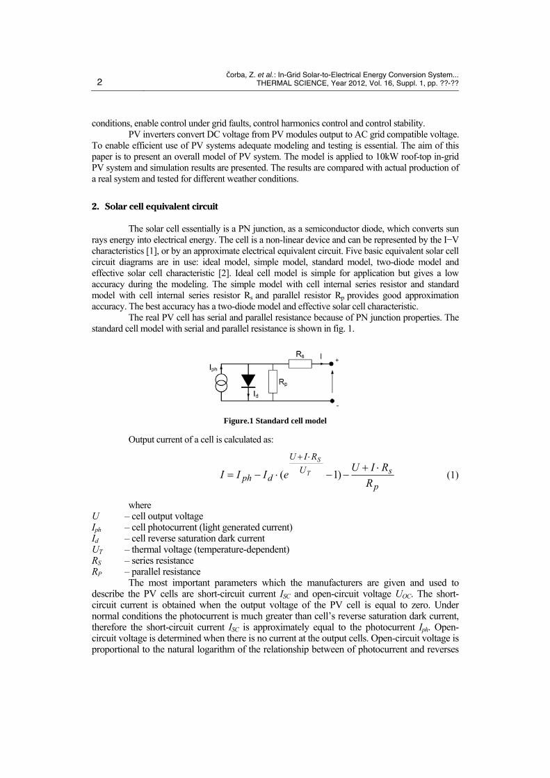
The simplest three-phase PV inverter topology is three-phase full-bridge topology. Regardless of the simplicity it is mostly used topology in practical realizations. These topology shows fig. 8. There is also a three-phase full-bridge PV inverter topology with split capacitor. This topology is equivalent to the three independent single-phase half-bridge PV inverters topology [9]. The third variant of three-phase PV inverter topology can be modularized topology, based on a three single-phase neutral-point clamped inverter.
Figure 8. Three-phase full-bridge topology
6. Photovoltaic power plant implementation
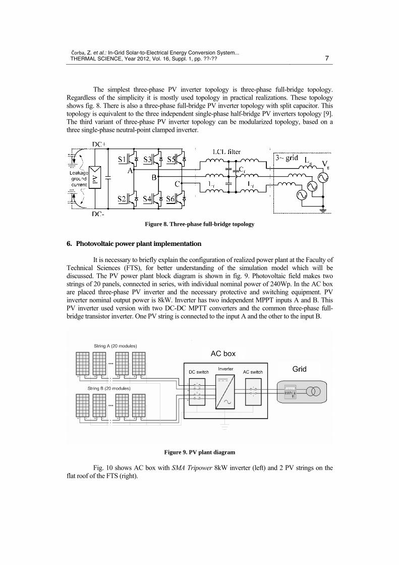
It is necessary to briefly explain the configuration of realized power plant at the Faculty of Technical Sciences (FTS), for better understanding of the simulation model which will be discussed. The PV power plant block diagram is shown in fig. 9. Photovoltaic field makes two strings of 20 panels, connected in series, with individual nominal power of 240Wp. In the AC box are placed three-phase PV inverter and the necessary protective and switching equipment. PV inverter nominal output power is 8kW. Inverter has two independent MPPT inputs A and B. This PV inverter used version with two DC-DC MPTT converters and the common three-phase full-bridge transistor inverter. One PV string is connected to the input A and the other to the input B.
Figure 9. PV plant diagram
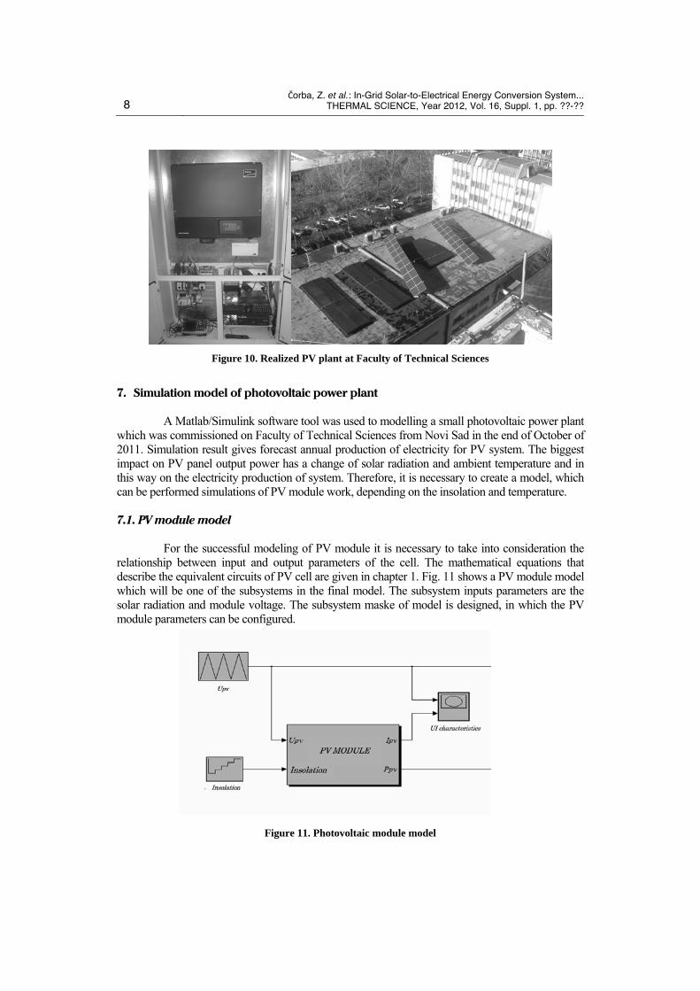
Fig. 10 shows AC box with SMA Tripower 8kW inverter (left) and 2 PV strings on the flat roof of the FTS (right).
8 Čorba, Z. et al.: In-Grid Solar-to-Electrical Energy Conversion System...
THERMAL SCIENCE, Year 2012, Vol. 16, Suppl. 1, pp. ??-??
Figure 10. Realized PV plant at Faculty of Technical Sciences
7. Simulation model of photovoltaic power plant
A Matlab/Simulink software tool was used to modelling a small photovoltaic power plant which was commissioned on Faculty of Technical Sciences from Novi Sad in the end of October of 2011. Simulation result gives forecast annual production of electricity for PV system. The biggest impact on PV panel output power has a change of solar radiation and ambient temperature and in this way on the electricity production of system. Therefore, it is necessary to create a model, which can be performed simulations of PV module work, depending on the insolation and temperature.
7.1. PV module model
For the successful modeling of PV module it is necessary to take into consideration the relationship between input and output parameters of the cell. The mathematical equations that describe the equivalent circuits of PV cell are given in chapter 1. Fig. 11 shows a PV module model which will be one of the subsystems in the final model. The subsystem inputs parameters are the solar radiation and module voltage. The subsystem maske of model is designed, in which the PV module parameters can be configured.
Figure 11. Photovoltaic module model

Čorba, Z. et al.: In-Grid Solar-to-Electrical Energy Conversion System...THERMAL SCIENCE, Year 2012, Vol. 16, Suppl. 1, pp. ??-?? 9
PV modules parameters which are installed at the PV plant and to be entered into the mask, at Standard Test Conditions are: Impp – module current at maximum power, Impp=8.01 A Umpp – module voltage at maximum power, Umpp=30 V Isc – module short-circuit current, Isc=8,56 A Uoc – module open-circuit voltage, Uoc=37.2 V α – short-circuit current temperature coefficient, α =0.05 %/°K β – open-circuit voltage temperature coefficient, β =-0.27 %/°K γ – maximum power temperature coefficient, γ =-0.45 %/°K
The module U-I characteristics are shown in fig. 12, for the different radiation and cell temperature of 20°C and 60°C. PV module nominal power is 240Wp.
Figure 12. Modules U-I characteristics
Fig. 12 shown U-P module characteristics for the same conditions which appropriate to U-I characteristics from the fig. 13.
Figure 13. Modules P-U characteristics

10 Čorba, Z. et al.: In-Grid Solar-to-Electrical Energy Conversion System...
THERMAL SCIENCE, Year 2012, Vol. 16, Suppl. 1, pp. ??-??
7.2. Model of annual power production
As mentioned, aim of the study is the assessment PV plant annual production by simulation, based on the input parameters of radiation and ambient temperature. Solar radiation and ambient temperature the surroundings of Novi Sad was determined using an interactive software PVGIS. The average daily global radiation for each month is input parameter of radiation. The PVGIS global clear-sky, global and diffuse average daily radiation is shown in fig. 14, for January and August. Radiation values are given for the inclined surface of 30 degrees. The modules at the PV plant are installed at the same inclined angle. In the model is considered that the temperature as an input parameter is the same and equal to the average daily temperature for the month, for each day during one month.
Figure 14. Global clear-sky, global and diffuse average daily radiation
The part of model with input parameters are average daily global radiation, average daily temperature for month and number of days in month are shown in fig 15.
The final model for the assessment of electricity production of the PV plant is shown in fig. 16. Final model consists few basic blocks which are the block of input parameters A, two block of photovoltaic arrays B1 and B2, two block of MPPT C1 and C2 and a DC to DC converter block D. A block of input parameters has been described and shown in Figure. Blocks B1 and B2 are identical and represent the PV string with 20 PV modules connected in series. Because inverter has two independent inputs, in the model is necessary to use two MPTT blocks whose outputs are connected to 2 independent DC/DC Boost converters.

Čorba, Z. et al.: In-Grid Solar-to-Electrical Energy Conversion System...THERMAL SCIENCE, Year 2012, Vol. 16, Suppl. 1, pp. ??-?? 11
Figure 15. The models input parameters
Figure 16. The realized PV plant model

12 Čorba, Z. et al.: In-Grid Solar-to-Electrical Energy Conversion System...
THERMAL SCIENCE, Year 2012, Vol. 16, Suppl. 1, pp. ??-??
Strings output are connected to the MPPT blocks input which output is reference current, which corresponds to maximum power point. The MPPT output reference currents are conducted to the PV strings inputs in order to control operating point during the simulation. To the D block inputs are connected the reference currents from both MPPT blocks and the appropriate voltages from PV strings.
7.3. Simulation results
The result of a simulation model is electricity energy generated per month, which is shown in fig. 17. The output values were obtained by the average daily global radiation. The sum of annual production by simulation model is 12160kWh.
0200400600800
1000120014001600
JanFeb
Mar
AprM
ayJun
JulAug
SepOct
NovDec
kW
h
Figure 17. Monthly energy production by simulation
Other than simulation of annual production, the analysis was made for a day. November’s sunny day was chosen. Changes of real solar radiation for the 18th November of 2011th are shown in fig. 18. These values of radiation are used as input parameter in the simulation model. In this way, as a result of simulation is obtained daily change of PV plant output power.
Figure 18. The real solar radiation and inverter real output power
Fig. 19 shows the inverter output power changes while the simulation model input

Čorba, Z. et al.: In-Grid Solar-to-Electrical Energy Conversion System...THERMAL SCIENCE, Year 2012, Vol. 16, Suppl. 1, pp. ??-?? 13
parameter is real daily radiation change.
Figure 19. The inverter simulated output power
The actual change of plant output power, during the day is shown in fig. 20. The rapid growth power is observed on the ascending part of curve, in the early morning. This is a consequence of the shadows termination on the one PV string, which model is not observed.
Figure 20. Actual changes of PV plant output power
8. Comparison with actual results
Comparison of simulation results and the PV plant actual production is possible for three months, because the plant is commissioned at the end of October 2011th. This comparison is presented in fig. 21. The time interval of three months is very short for a good assessment of the validity of the simulation. Also should not be forgotten, that the simulation results obtained by the ten-years average values of input parameters. In November, by the results of the simulation, production was higher for 15kWh than to the actual production. The PV plant electricity production is slightly higher than the results of simulation in December and January. For these two months the average difference is 30 kWh, which is equal with the average production during a one sunny day in January.

14 Čorba, Z. et al.: In-Grid Solar-to-Electrical Energy Conversion System...
THERMAL SCIENCE, Year 2012, Vol. 16, Suppl. 1, pp. ??-??
0
100
200
300
400
500
600
700
Nov
Dec
Jan
kWh
Simulation [kWh] Actual production [kWh]
Figure 21. Comparison of simulation results and actual values
The real and simulation based cumulative production is shown in fig. 22. Cumulative production is shown for the first three months of plant operation. The actual production is higher by 130kWh at the end of the third month of plant operation.
-100
100
300
500
700
900
1100
1300
1500
Nov Dec Jan
[kW
h]
Simulation [kWh] Actual production [kWh]
Figure 22. Cumulative production
Fig. 23 shows the comparison between simulation result and electricity production obtained using PVGIS. In months with more clouds PVGIS gives somewhat higher values when the average cloudiness lowers, values of the simulation models are greater. Results of these differences are that the sum of annual production by PVGIS is 11400kWh and by simulation model is 12160kWh. Difference of 6% is caused by various handling of the temperature values during the simulation and use of PVGIS. For each day, a simulation model using the average daily temperature for the considered month is applied. PVGIS is used from its database the temperature change during the day, which depending on the radiation.

Čorba, Z. et al.: In-Grid Solar-to-Electrical Energy Conversion System...THERMAL SCIENCE, Year 2012, Vol. 16, Suppl. 1, pp. ??-?? 15
0200400
600800
10001200
14001600
JanFeb
Mar
AprM
ayJun
JulAug
SepOct
NovDec
kW
h
Simulation [kWh] PVGIS[kWh]
Figure 23. Comparison of simulation results and PVGIS
9. Conclusions
Installed PV power plant at the Faculty of Technical Sciences enables the validation of simulation methods. On the other hand, various simulation methods could help to optimize PV system. Detailed analysis of PV plant operation and comparison with simulation model will be possible to make after a longer period of exploitation. The further improvement of the simulation model will allow the less output errors. The better prediction of PV plant production can be enabled by entering accurate input parameters. Integration of input parameters, like ambient temperature and solar radiation, based on the meteorological forecasts will allow the prediction of PV plant production for the next few hours or days.
References
[1] Guney, I., Onatte, N., Technological status and market trends of photovoltaic cell industry, WSEAS Transactions on Electronics, 5 (2008), 7
[2] Wagner, A., Peak-power and internal series resistance measurement under natural ambient conditions, Proceedings EuroSun 2000, Copenhagen, 2000
[3] Huan-Liang, T., Ci-Siang, T., Yi-Jie, S., Development of Generalized Photovoltaic Model using MATLAB/SIMULINK, Proceedings WCECS 2008, San Francisco, USA
[4] Schimpf, F., Norum, E., Grid connected Converters for Photovoltaic, State of the Art, Ideas for Improvement of Transformerless Inverters, NORPIE/2008, Nordic Workshop on Power and Industrial Electronics, 2008
[5] Baekhoej, S., Pedersen, J., Blaabjerg, F., Power Inverter Topologies for Photovoltaic Modules – A IEEE Review, 2002
[6] Teodorescu, R., Lissere, M., Rodriguerz, P., Grid converters for photovoltaic and wind power system, John Wiley and Sons, Ltd, 2011
[7] German Patent H5-Topology: DE 10 2004 030 912 B3, issued 19.01.2006 [8] German Patent HERIC-Topology: DE 102 21 592 A1, issued 04.12.2003 [9] Kerekes, T., Teodorescu, R., Liserre, M., Evaluation of Three-Phase Transformerless Photovoltaic
Inverter Topologies, IEEE Transaction on Power Electronics, 24 (2009), 9

16 Čorba, Z. et al.: In-Grid Solar-to-Electrical Energy Conversion System...
THERMAL SCIENCE, Year 2012, Vol. 16, Suppl. 1, pp. ??-??
Paper submitted: February 24, 2012 Paper revised: April 12, 2012 Paper accepted: April 19, 2012