in harbor underwater threat detection/identification using active
TRANSCRIPT

REPOT DCUMNTATON AGEForm ApprovedREPOT DCUMNTATON AGEOMB No. 0704-0188
The puylic reportdng burden for this collection of information is estimated to average 1 hour per response, including the time for reviewing instructions, searching existing data sources,gathering and maintaining the data needed, and completing and reviewing the collection of information. Send comments regarding this burden estimate or any other aspect of this collection ofinformation, including suggestions for reducing the burden, to the Department of Defense, Executive Services and Communications Directorate (0704-0188). Respondents should be awarethat ntotwithstanding any other provision of law, no person shall be subject to any penalty for failing to comply with a collection of information if it does not display a currently valid OMScontrol number.PL!EASE DO NOT RETURN YOUR FORM TO THE ABOVE ORGANIZATION.
1, REPORT DATE (DD-MM-YYYY) 2. REPORT TYPE 3. DATES COVERED (From - To)29-06-2005 Conference Proceedings (not refereed)
4, TITLE AND SUBTITLE 5a. CONTRACT NUMBER
In Harbor Underwater Threat Detection/Identification Using Active Imaging
5b. GRANT NUMBER
5c. PROGRAM ELEMENT NUMBER
0602435N
6. A•THOR(S) 5d. PROJECT NUMBER
Wpidemann, Alan D., Fournier, G.R., Forand, J.L., Mathieu, P.
5e. TASK NUMBER
5f. WORK UNIT NUMBER
73-6867-75-5
7." PERFORMING ORGANIZATION NAME(S) AND ADDRESS(ES) 8. PERFORMING ORGANIZATION
NaYvl Research Laboratory REPORT NUMBEROceanography Division NRL/PP/7330--05-5168
$tepnis Space Center, MS 39529-5004
"0. OPQNSORING/MONITORING AGENCY NAME(S) AND ADDRESS(ES) 10. SPONSOR/MONITOR'S ACRONYM(S)
Of•ice of Naval Research ONR
$00 N, Quincy St.Arlington, VA 22217-5660 11. SPONSOR/MONITOR'S REPORT
"NUMBER(S)
12. DISTRIBUTION/AVAILABILITY STATEMENT
Approved for public release, distribution is unlimited.
13. SUPPLEMENTARY NOTES
14. ABSTRACTW•e present results from trials of the LUCIE 2 (Laser Underwater Camera Image Enhancer) conducted in Halifax Harbor, Nova Scotia, Canada and Esquimalt
4arbor, Victoria, British Columbia, Canada. LUCIE 2 is a new compact laser range gated camera (10 inches in diameter, 24 inches in length, and neutrally buoyantin water) originally designed to improve search and recovery operations under eye safe restrictions. The flexibility and eye safety of this second generation LUCIE
lugkes' it a tool for improved hull searches and force protection operations when divers are in the water attempting to identify bottom lying objects..The camera isequippgd with a full image geo-positioning system. To cover various environmental and targets size conditions, the gate-delay, gate width, polarization and viewinga•,nd illuminating angles can be varied as well. We present an analysis on the performance of the system in various water conditions using several target types and acompprison with diver and camera identification. Coincident in-situ optical properties of absorption and scattering were taken to help resolve the environmentalinformation contained in the LUCIE image. Several new capabilities are currently being designed and tested., among them a differential polarization imaging system,
a stabilized line of sight system with step-stare capability for high resolution mosaic area coverage, a precision dimensioning system and a diver guided and operatedygrsion.
15. SUBJECT TERMS
Aptivq underwater imaging, underwater detection, underwater identification, range gating
I 0, $ECURITY CLASSIFICATION OF: 17. LIMITATION OF 18. NUMBER 19a. NAME OF RESPONSIBLE PERSON'.' J3EPORT b. ABSTRACT c. THIS PAGE ABSTRACT OF Alan Weidemann
PAGES-Unclassified Unclassified Unclassified UL 13 19b. TELEPHONE NUMBER (Include area code)Unclassified 228-688-6232
Standard Form 298 (Rev. 8/98)Prescribed by ANSI Std. Z39.18

In harbor underwater threat detection/identificationusing active imaging
Alan Weidemanna, Georges R. Fournierb, L. Forandb and P. Mathieub"aNaval Research Laboratory, Stennis Division, Stennis Space Center, Stennis Mo....bDRDC-Valcartier, 2459 Pie-XI Blvd. North, Val Belair, Quebec, Canada, G3J 1X5
ABSTRACT
We present results from trials of the LUCIE 2 (Laser Underwater Camera Image Enhancer) conducted in HalifaxHarbor, Nova Scotia, Canada and Esquimalt Harbor, Victoria, British Columbia, Canada. LUCIE 2 is a new compactlaser range gated camera (10 inches in diameter, 24 inches in length, and neutrally buoyant in water) originally designedto improve search and recovery operations under eye safe restrictions. The flexibility and eye safety of this secondgeneration LUCIE makes it a tool for improved hull searches and force protection operations when divers are in thewater attempting to identify bottom lying objects. The camera is equipped with a full image geo-positioning system.To cover various environmental and targets size conditions, the gate-delay, gate width, polarization and viewing andilluminating angles can be varied as well. We present an analysis on the performance of the system in various waterconditions using several target types and a comparison with diver and camera identification. Coincident in-situ opticalproperties of absorption and scattering were taken to help resolve the environmental information contained in theLUCIE image. Several new capabilities are currently being designed and tested., among them a differential polarizationimaging system, a stabilized line of sight system with step-stare capability for high resolution mosaic area coverage, aprecision dimensioning system and a diver guided and operated version.
Keywords: Active underwater imaging, underwater detection, underwater identification, range gating
1. INTRODUCTION
What makes the problem of in harbor underwater threat detection and identification such a difficult and frustrating taskis the fact that ultimately identification must be carried out by visual means in waters that are generally turbid. Theseoperations must be carried out both night and day and in shadowed and dark areas under ships and under docks.Therefore one cannot rely on having any kind of natural illumination. The necessity of using light sources that are co-located with the camera compounds the problem as a standard camera is often blinded by the backscattered light comingfrom the nearby scattering particles suspended in the water and lying between the target and the camera. Consequentlyto identify objects under these low visibility conditions divers or Remotely Operated Vehicles (ROVs) equipped withstandard cameras and lighting systems must get very close to the target. Often divers and vehicles get so close that theydisturb the silt and sediments lying over the target or on the bottom and create their own cloud of scattering particles.This additional turbidity can be quite large and the only practical solution is to stop all motion and wait for the currentto advect the cloud from the target area. In the case of an ROV this basically means stopping the engines and lying onthe bottom until the cloud dissipates. As subsurface inner harbor currents are often weak, this can result in waiting aminute or more in many cases. This increases the "time" required for the inspection of the target area.
A collateral and equally significant problem induced by the low visibility is the absence of knowledge and confusionabout absolute position that can affect both divers and ROV operators. This can result in "holidays" in the coverage orinspection and implies the need for accurate underwater positioning or geo-referencing. In order to ensure completecoverage or inspection of an area, a dock or a ships hull, the positioning accuracy must be kept less than both theimaging range and the field of view (FOV) of the camera system. Sometimes potential targets have been detected andpossibly classified by other sensors, sonar systems for instance. The small range of the camera can render the cross-sensor target handoff extremely difficult and time consuming. In order to operate efficiently in the in harbor underwaterthreat identification mission, electro-optics systems must maximize their range of operation and therefore must bedesigned to reduce, or if possible eliminate, the effects of turbidity. At the very least these systems should increase the
Photonics for Port and Harbor Security, edited by Michael J. DeWeert,-Theodore T. Saito, Proceedings of SPIE Vol. 5780 (SPIE, Bellingham, WA, 2005)S20060130277-786X/05/$1 5" dol: 10.1117/12.603601
- u6 UcO
identification range sufficiently to ensure that in high silt environments, divers or ROV systems do not create their ownclouds.
There are three main benefits of this increased range. The first is a larger search swath, which leads to shorter operationtimes for a given required coverage. The second is a sufficiently high enough bottom or target clearance to carry outtarget identification in stride, i.e. without the obligation of frequently setting the ROV on the bottom. The last benefit isthe ease of cross-sensor target handoff, including the assurance that both sensors did indeed look at the same target. Inaddition, even when the electro-optic system is carried by a ROV, divers must be used to prosecute whatever targetshave been found. The system should therefore ideally be sufficiently eye safe to be operable in the presence of divers.Systems that use a combination of a short green laser pulse with a time gated image intensifier in order to enhance therange of visibility underwater occurred almost as soon as components were available. In such systems, a laser pulse issent out and after a suitable delay the camera gate is turned on. This minimizes the intense backscatter from the watercolumn lying between the target of interest and the camera from being recorded on the image since the camera's shutteris closed precisely during the time this radiance would enter the fore-optics.
In the course of the past few years, we developed such an underwater range gated active imaging system (Laser CameraImage Enhancer LUCIE) originally for the express purposes of visually identifying bottom-laying mines and helping inunderwater search and recovery operations. The system was found to have a range of three to five times the range of astandard camera and this range increase was experimentally shown to be in many cases sufficient to allow on the flytarget identification with a ROV. The system uses a high repetition rate diode pumped doubled Neodymium Vanadategreen laser with seven nanoseconds pulse widths. The high repetition rate means that the applicable eye safetyconditions depend on average power density considerations and not on the single pulse total energy density criterion.The average eye safe power level is therefore higher by a factor of approximately one thousand, when compared withfor example a 10 Hz flash lamp pumped doubled YAG laser. The system is eye safe at 50 cm in its wide illumination(800 milliradians) beam configuration and 2 meters in its narrow (200 milliradians) illumination beam configuration. Iftotal eye safety is required, a simple factor of 10 notch filter could be incorporated in the diver mask. This still allowssufficient "through the mask transmission" in the blue and green to not hinder normal diver vision. The LUCIE systemtherefore satisfies both of our criteria for an effective in harbor electro-optic detection system.
2. EVOLUTION OF THE LUCIE SYSTEM
The LUCIE underwater range-gated imaging system has evolved through two very different generations. The firstsystem' used a compact high efficiency laser diode pumped Nd-YAG doubled into the green by crystals of either BBOor KTP. Two versions of this first generation system underwent a series of trials in various environments ranging fromharbor to open ocean. Both versions were mounted on a Remotely Operated Vehicle (ROV) and tested using long dwelltimes required for reliability testing, on a bottom-resting platform with pan and tilt capability. During all the varioustrials, simultaneous measurements were taken of water column the absorption and scattering coefficients along with thenear forward scattering phase function. These measurements were carried out using a near forward nephelometer andtransmissometer (NEARSCAT). These simultaneous measurements 2 allowed us to both model and extrapolateperformance data to waters with different properties.
Both versions of the camera proved to be extremely reliable. In cases were there was no or little natural illumination,and one had to rely on onboard lighting systems, the range gated system allowed one to extend the useful imaging rangefrom a factor of three to five when compared to a normal camera with 500 watt quartz-iodine lamps. We found that inmany circumstances, typical survey and identification missions could be carried out approximately 10 times faster thanwith standard imaging equipment. Part of this speed increase was due to the larger coverage due to the extended range.Another significant contributor to the efficiency of survey was the capability of the ROV to hover and image at asufficient distance from sandy or muddy bottoms that its own motors did not raise significant amounts of scatteringmaterial in the water column. We did not foresee this highly nonlinear effect on identification mission effectivenessbefore the trial results were analyzed.
Our original versions of LUCIE were built to allow a great deal of experimental flexibility and were fitted on a largeROV (Hysub 5000 from ISL). They were contained in a set of 3 joined cylinders 30 cm in diameter and 1 meter long.The system weighed 300 kilos and required 750 watts of inrush power and 500 watts of continuous power. This large
60 Proc. of SPIE Vol. 5780
size made the system difficult and expensive to operate. We therefore decided to investigate the feasibility tominiaturize the system without significant sacrifice to system performance, thus increasing the ease of operation and theoverall utility to other mission areas.
One of the success stories of early trials was the extraordinary reliability of the high repetition rate diode pumpeddoubled Neodymium laser. In several instances the first camera was immersed and operated underwater for severaldays. After being in storage for over a year, the camera was also brought back to full functionality and readiness in lessthan 24 hours. The delay was due to a small leak that had developed in a seal of the liquid cooling system of the laser.The second important successful part of the original design was the inherent eye safety of the high repetition rate diodepumped lasers. Because of the high repetition rate, the eye damage threshold for the pulsed laser becomes identical tothe CW damage limit. This much higher wattage figure means that even in clear waters the system is eye-safe at amaximum distance of 1.5 meters from the aperture. This allowed divers to operate around the camera while it was inoperation. [This alone improved the evaluation of the systems search rate capabilities relative to those of divers]. Wetherefore keep this approach in our second-generation system. We decided, however, to use an air and conductioncooled laser to both alleviate weight and ensure against potential system leaks. Consequently our new camera is acompletely dry system, a feature which considerably enhances its long term reliability. The high repetition rate alsoimplies that the in-water speckle is averaged out over each frame. This in itself is a significant benefit if we wish toapply modem image enhancement techniques to the results. As stated above, the camera uses an air cooled NeodymiumVanadate laser with a KTP doubling crystal. The doubled output at 532 nm is 1.50 watt average in water at a repetitionrate of 22 kHz with a pulse length of 5 ns. The average power is, however, sensitive to the diode temperature. Areduction of 3 degrees centigrade from a nominal set point of 27 degrees will reduce the power by 50%. This thenrequired that the overall system temperature needs to be stabilized by a sensitive controller driving an array of Peltiercoolers/heaters placed underneath the laser enclosure.
The most desirable improvements that were identified from an analysis of our original results were:"* Smaller size, weight and power"* Flat-field initial laser illumination matched to camera FOV"* Predictable illumination degradation"* Fixed beehive pattern removal (removal of minifier)"* Higher resolution"* Larger FOV"* Programmable AGC"* Optimized signal processing (Poisson noise dominance)"* Improved user interface
In our second-generation camera, the size has been reduced from the heavy 3 cylinders to one cylinder 25X70 cm inlength and weighting 45 kilos. The power consumption has also been reduced by more than a factor of 3 to an average175 watts. The illumination system is controlled by a holographic beam shaper that produces a flat illumination fieldwith a 4/3 aspect ratio. This aspect ratio matches the field of view (FOV) of a standard video camera. The intensityvaries by less than 5% over 90% of the FOV. Given an initial intensity distribution of this type it is relatively easy tocompute its transition to a Gaussian shape illumination as the beam propagates through natural waters with their typicalforward peaked scattering phase functions. The spatial degradation of the illuminating field is predictable at all zoomsettings and ranges3 4. This allows numerical intensity compensation algorithms to be applied in the new design.
One extremely annoying feature of intensified cameras is the appearance of a beehive pattern superimposed on theimage. This beehive pattern is due to the varying transmission through the fiber bundles (minifiers) used to collect thelight output of the phosphor on the back plate of the image intensifier and reduce it to a size appropriate to the CCDarray of the video camera. In order to eliminate this effect our camera now uses a high aperture (f=0.8) lens to image thephosphor directly on the CCD. The light collection efficiency is reduced by a factor of two but this is irrelevant sincewe use a gated tube in chevron configuration with a luminous gain of 1,000,000 that can count individual photons ifrequired. It can still count photons even with the reduced efficiency of the lens over the fiber bundle. We have foundthat the image is more pleasing to the operator and much easier to apply image enhancement algorithms too.
Proc. of SPIE Vol. 5780 61

Another improvement is that a slightly higher resolution is obtained by using a 25mm diameter photo-cathodeintensifier tube rather than the usual 18 mm type. The photo-cathode has a low noise (500 counts st cm-2) T type S20coating with a 10% quantum efficiency at 532 nm. We have found that our new camera is able to easily resolve 200 linepairs across the width of the screen. The lens system is now 10 cm in diameter with a zoom range of 16 mm to 160 mmat an f=1.8. The lens has an auto-iris control and fully motorized focus and zoom. Both camera and illuminator can bezoomed from 80 to 800 mr in water. The laser divergence and zoom lens system can be slaved together to ensuremaximum uniform illumination over the entire range of field of views. This larger field of view is achieved at the samesensitivity level as in our first generation system because of the larger diameter photo-cathode. The intensifier gatedelay can be varied from 0 to 500 ns and the gate width can be increased from 3 ns to 500 ns. Diagrams and a laboratoryphotograph of this new system are shown in the next three figures. Figure 1 is a schematic front view of this newsystem. Figure 2 is a side view of the same LUCIE2 system showing a block diagram of the components. Figure 3 is apicture of the actual camera system.
System Front View
Diode Pumped
Doubled Laser
Zoom Lens
Camera Control Board
Camera
Former
Figure 1. Schematic of the front view of the LUCIE2 range gated imager. The zoom lens is 10 cm in diameter and the laser beam exit port is2.5 cm in diameter. The ports are separate to avoid back scattering of the laser beam in the receiving optics.
System Top View
Zoom LensSCamera and Laser Control Board
SGated Intensified: : Careera
Diode Pumaped Laser, Doubler 7
and Beam Former
Figure 2. Schematic of the top view of the LUCIE2 range gated imager showing a block diagram of the components.
62 Proc. of SPIE Vol. 5780
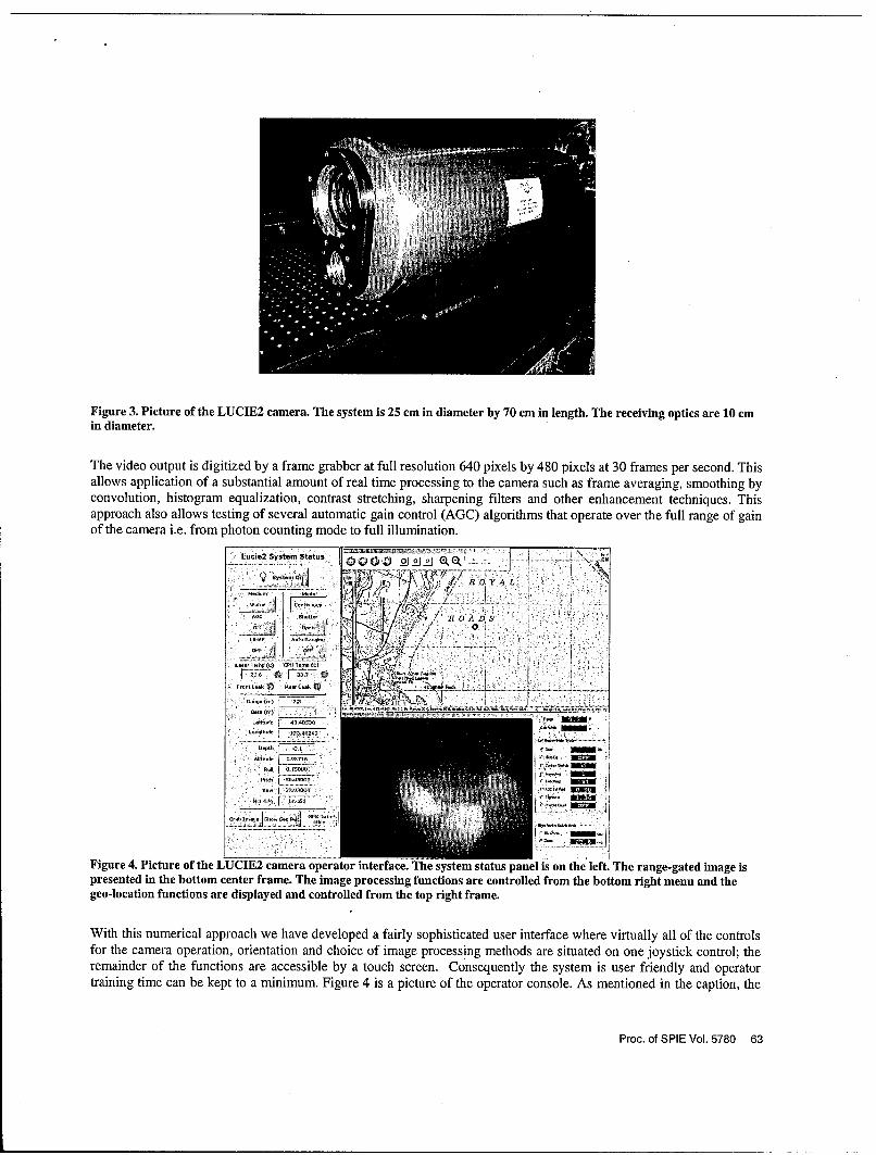
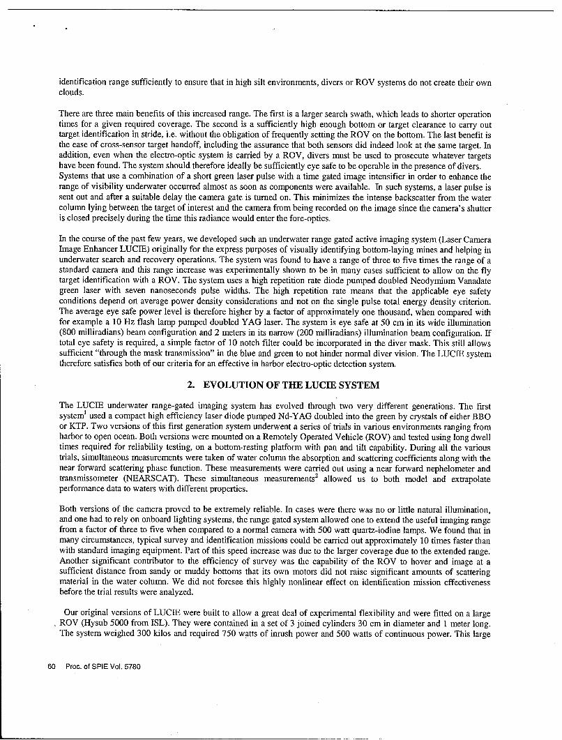
Figure 3. Picture of the LUCIE2 camera. The system is 25 cm in diameter by 70 cm in length. The receiving optics are 10 cmin diameter.
The video output is digitized by a frame grabber at full resolution 640 pixels by 480 pixels at 30 frames per second. Thisallows application of a substantial amount of real time processing to the camera such as frame averaging, smoothing byconvolution, histogram equalization, contrast stretching, sharpening filters and other enhancement techniques. Thisapproach also allows testing of several automatic gain control (AGC) algorithms that operate over the full range of gainof the camera i.e. from photon counting mode to full illumination.
Lucde2 System Status 0 , o o oi
if:T : .. :
AUG 5,U•t, IIII 1ROADS
~~~~~~~~~~. ...... . .. , : : :: : . . . . . ... .. .
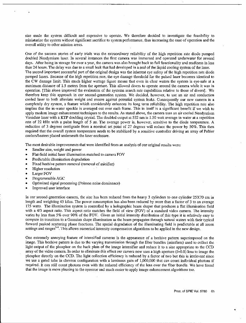
Figure 4. Picture of the LUCIE2 camera operator interface. The system status panel is on the left. The range-gated image ispresented in the bottom center frame. The image processing functions are controlled from the bottom right menu and thegeo-location functions are displayed and controlled from the top right frame.
With this numerical approach we have developed a fairly sophisticated user interface where virtually all of the controlsfor the camera operation, orientation and choice of image processing methods are situated on one joystick control; theremainder of the functions are accessible by a touch screen. Consequently the system is user friendly and operatortraining time can be kept to a minimum. Figure 4 is a picture of the operator console. As mentioned in the caption, the
Proc. of SPIE Vol. 5780 63

system status and control panel is on the left. The range-gated image as enhanced by real time image processing ispresented in the bottom center frame. The image processing functions are controlled from the bottom right menu and allcompatible processing functions can be turned on simultaneously by the operator. The geo-location functions aredisplayed and controlled from the top right frame. These functions allow one to navigate over the map, to mark targets,and to view the swath covered so far by the imaging system. In the particular case shown, the ship and ROV and camerawere operating in Esquimalt Harbor just outside of Victoria on the island of Vancouver.
Because of its relatively small size, the camera can be operated either from a small cradle directly attached to a boat inshallow waters, or mounted on a ROV for deeper water operations. In the trials in Halifax in February 2002, the cradlewas extensively used. In the trial in Esquimalt Harbor in March 2004, both the cradle and a ROV were used. Figure 5shows LUCIE mounted on a Deep Ocean Engineering Phantom class ROV during the Esquimalt trials. As shownLUCIE2 is encased in a custom tailored envelope made of standard wet suit material. This envelope helps to reduce thepower expenditure necessary to control the internal temperature of the system. As mentioned above, this control isrequired to ensure that the laser and frequency doubling system function at peak efficiency.
Figure 5. Picture of the LUCIE2 camera mounted on the side of a Deep Ocean Engineering Phantom ROV.LUCIE2 is encased in a custom tailored enclosure made of standard wet suit material.
64 Proc. of SPIE Vol. 5780
3. IN SITU OPTICAL MEASUREMENTS
In trials of the previous system we carried out simultaneous measurements of the relevant optical properties of thewaters in which we were operating. This data, when combined with simple models, gives insight into the potentialsystem performance in varied coastal and harbor conditions. The measurements included absorption and attenuation atnine wavelengths (WetLabs Inc., ac-9 plus), backscattering at 140 degrees, and radiance attenuation (HobiLabs Inc., a-beta at 532 nm), scattering at 100, 125 and 150 degrees (Wetlabs ECOVSF), and CTD. Figure 6 shows a typicalexample of the vertical profile of both absorption and extinction coefficients measured in the inner harbor in Halifax100 meters away from the untreated exhaust from a main sewer pipe. In this case the water temperature was 10C.
BEAM ATTENUATION AND ABSORPTION AT 532 NM0-
E 4- :
C)
'.•
8 ' . C(532)]
10-1= Li
12-
0.0 0.2 0.4 0.6 0.8 1.0 1.2 1.4
C(532) and a(532) as rn1
Fig. 6. Depth profile of absorption and beam attenuation at 532 nm showing increase from 0.9 to 1.2 m"1 nearthe bottom for c (532).
In the Halifax trials the work was carried from a small boat moored to a main pier. The optical properties as a functionof depth changed with the tidal cycle, sewage discharge, and wind direction. Scattering layers were found at both thesurface and at depth depending on the tidal cycle, wind, and discharge. The measurements of the optical properties ofthe water column are generally of good quality. In some cases the presence of large quantities of big particles(centimeter size and larger) was evident. Since these particles can substantially or completely block the optical paths ofthe instruments, their effects on absorption, scattering and the phase function, are not properly accounted for by theinstrumentation used or there "in-frequency" in a statistical sense means that they are "seldom measured." In the caseof the very particular waters we were operating in, the results are therefore a lower limit on the values of theseparameters. We have not yet found a reliable method to properly compensate this effect.
The same measurements were carried out in the Esquimalt trials of March 2003 but we did not encounter the sameproblem since the trials were carried out in this case either from a ROV or directly from the rear deck of the HMCSWhitehorse, a Canadian coastal patrol vessel whose primary mission is to carry out detailed side scan sonar surveys ofthe harbor and its approaches. In this case we were well removed from any sewage outlet. Note that the simultaneousmeasurement of the total scattering coefficient at several wavelengths allows one to approximate the near forward anglebehavior of the phase function and to determine the precise inverse power dependence of the particle size distribution.With this information, it is then possible by using a few large angle scattering measurements at one wavelength to fit thecomplete experimental data by a phase function model [5]-[6]. This model depends only on the inverse power as afunction of size of the particle size distribution and on the average relative index of refraction of the particles. Thecurrent sets of measurements are thus sufficient for us to ultimately determine to a satisfactory accuracy all the relevant
Proc. of SPIE Vol. 5780 65
parameters necessary to build a complete theoretical model of the experiment. This model will be a considerable help inthe further analysis and generalization of our trial results.
4. THE HALIFAX TRIALS AND RESULTS
The first trials were carried out between February 13 2002 and February 21 2002 along side pier 9 in Halifax harbor. Aspreviously mentioned, the test site was located less than a hundred yards from a main untreated sewer outlet, a situationthat created a serious challenge to the imaging system. The water depth at the test site was 10 meters and the level ofnatural light at the bottom was high. The LUCIE2 underwater enclosure was first mounted on a large pan and tilt mountthat could rest on the bottom and was hydraulically powered. A small aperture large depth of field Fischers divercamera with two 150 watts quartz-iodine lamps was attached to the mount. This camera provided both the standardsource of illumination for normal camera use, and served as a second reference for performance comparison. The firstreference is the camera in LUCIE2 itself, which can be used in un-gated mode as a standard high sensitivity videocamera.
Several sets of targets were used during the trial. The first set of diver visibility targets used was a set developed by W.Mcbride and T. Bowers of Planning Systems Incorporated. These consisted of calibrated sets of black line pairs on awhite background. The line widths ranged from 1 mm to 128 mm on two different panels. The line spacing inmillimeters, which is double the line width, is indicated on the side of each line pair set. At different times during thetrial we also used other target types. We used a line set (white lines on black background), which had served in all ourprevious experiments. The line widths range from 1.5 mm to 48 mm. Each subsequent line pair set is the double in sizeof the previous set. Following the procedures we had established during our previous trials using the first generationimager, the various targets were imaged at several different ranges under as many different environmental conditions aspossible. Coincident measurements of the optical properties of the water column were carried out.
Because water depth was shallow (10 m) and background illumination high, we had the opportunity to measure theperformance of the camera against that of divers during this field test. To carry out the comparison, we used the blackline against white background targets. A measuring tape was attached to the target and the divers moved back from thetarget noting at what distance they stopped distinguishing between the discrete line pairs in a target set, and when the setitself was indistinguishable.
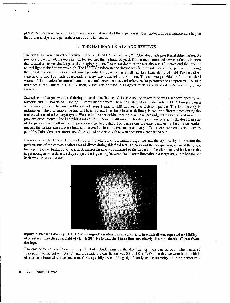
Figure 7. Picture taken by LUCIE2 at a range of 5 meters under conditions in which divers reported a visibilityof 3 meters. The diagonal field of view is 200. Note that the 16mm lines are clearly distinguishable (4 th row fromthe top).
The environmental conditions were particularly challenging on the day this test was carried out. The measuredabsorption coefficient was 0.2 m' and the scattering coefficient was 0.8 to 1.0 m -. On that day we were in the middleof a sewer plume discharge and a nearby ship's bilge was adding significantly to the turbidity. In these particularly
66 Proc. of SPIE Vol. 5780
difficult conditions, the divers reported a visibility range of approximately 3 meters (10 feet). Beyond this range theycould still distinguish the presence of a white diffuse target but they could not make out any details whatsoever.
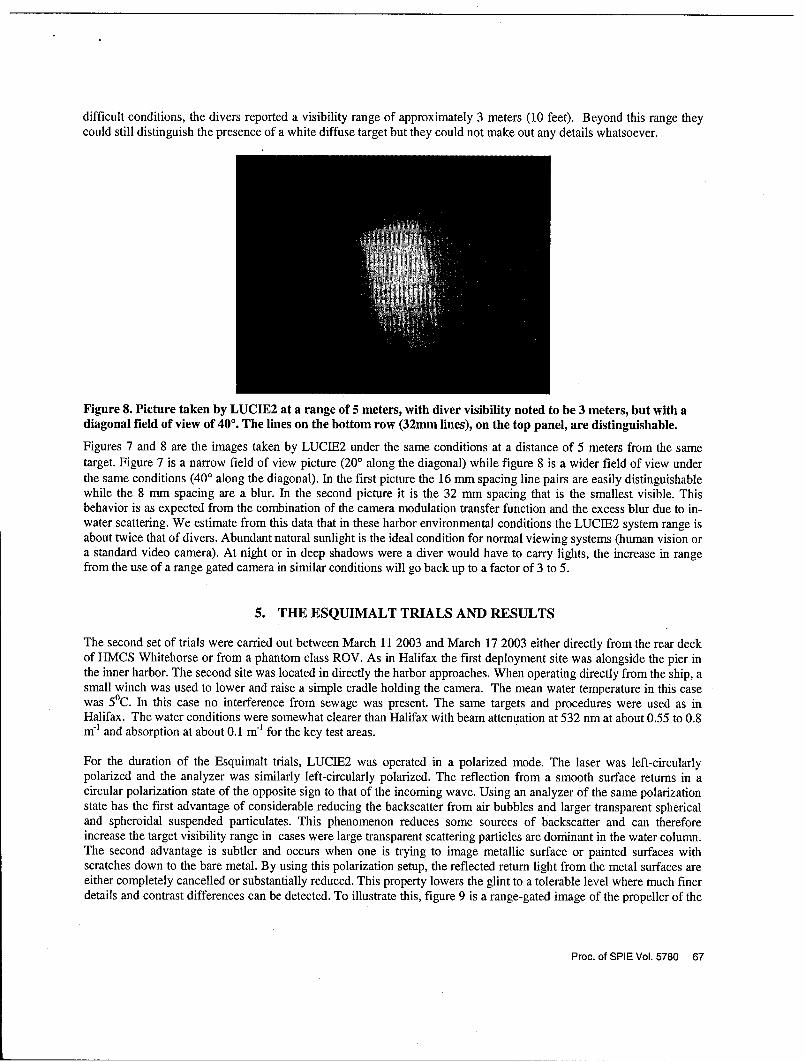
Figure 8. Picture taken by LUCIE2 at a range of 5 meters, with diver visibility noted to be 3 meters, but with adiagonal field of view of 400. The lines on the bottom row (32mm lines), on the top panel, are distinguishable.
Figures 7 and 8 are the images taken by LUCIE2 under the same conditions at a distance of 5 meters from the sametarget. Figure 7 is a narrow field of view picture (200 along the diagonal) while figure 8 is a wider field of view underthe same conditions (40' along the diagonal). In the first picture the 16 mm spacing line pairs are easily distinguishablewhile the 8 mm spacing are a blur. In the second picture it is the 32 mm spacing that is the smallest visible. Thisbehavior is as expected from the combination of the camera modulation transfer function and the excess blur due to in-water scattering. We estimate from this data that in these harbor environmental conditions the LUCIE2 system range isabout twice that of divers. Abundant natural sunlight is the ideal condition for normal viewing systems (human vision ora standard video camera). At night or in deep shadows were a diver would have to carry lights, the increase in rangefrom the use of a range gated camera in similar conditions will go back up to a factor of 3 to 5.
5. THE ESQUIMALT TRIALS AND RESULTS
The second set of trials were carried out between March 11 2003 and March 17 2003 either directly from the rear deckof HMCS Whitehorse or from a phantom class ROV. As in Halifax the first deployment site was alongside the pier inthe inner harbor. The second site was located in directly the harbor approaches. When operating directly from the ship, asmall winch was used to lower and raise a simple cradle holding the camera. The mean water temperature in this casewas 5°C. In this case no interference from sewage was present. The same targets and procedures were used as inHalifax. The water conditions were somewhat clearer than Halifax with beam attenuation at 532 nm at about 0.55 to 0.8m- and absorption at about 0.1 m7l for the key test areas.
For the duration of the Esquimalt trials, LUCIE2 was operated in a polarized mode. The laser was left-circularlypolarized and the analyzer was similarly left-circularly polarized. The reflection from a smooth surface returns in acircular polarization state of the opposite sign to that of the incoming wave. Using an analyzer of the same polarizationstate has the first advantage of considerable reducing the backscatter from air bubbles and larger transparent sphericaland spheroidal suspended particulates. This phenomenon reduces some sources of backscatter and can thereforeincrease the target visibility range in cases were large transparent scattering particles are dominant in the water column.The second advantage is subtler and occurs when one is trying to image metallic surface or painted surfaces withscratches down to the bare metal. By using this polarization setup, the reflected return light from the metal surfaces areeither completely cancelled or substantially reduced. This property lowers the glint to a tolerable level where much finerdetails and contrast differences can be detected. To illustrate this, figure 9 is a range-gated image of the propeller of the
Proc. of SPIE Vol. 5780 67
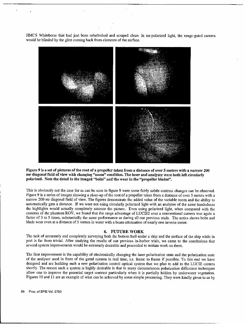
HMCS Whitehorse that had just been refurbished and scraped clean. In un-polarized light, the range-gated camerawould be blinded by the glint coming back from elements of the surface.
Figure 9 is a set of pictures of the root of a propeller taken from a distance of over 5 meters with a narrow 200mr diagonal field of view with changing "zoom" condition. The laser and analyzer were both left circularlypolarized. Note the detail in the imaged "bolts" and the wear in the "propeller blades".
This is obviously not the case for as can be seen in figure 9 were some fairly subtle contrast changes can be observed.Figure 9 is a series of images showing a close-up of the root of a propeller taken from a distance of over 5 meters with anarrow 200 mr diagonal field of view. The figures demonstrate the added value of the variable zoom and the ability toautomatically gate a distance. If we were not using circularly polarized light with an analyzer of the same handednessthe highlights would actually completely saturate the picture. Even using polarized light, when compared with thecameras of the phantom ROV, we found that the range advantage of LUCIE2 over a conventional camera was again afactor of 3 to 5 times, substantially the same performance as during all our previous trials. The series shows bolts andblade wear even at a distance of 5 meters in water with a beam attenuation of nearly one inverse meter.
6. FUTURE WORKThe task of accurately and completely surveying both the bottom hull under a ship and the surface of the ship while inport is far from trivial. After studying the results of our previous in-harbor trials, we came to the conclusions thatseveral system improvements would be extremely desirable and proceeded to initiate work on them.
The first improvement is the capability of electronically changing the laser polarization state and the polarization stateof the analyzer used in front of the gated camera in real time, i.e. frame to frame if possible. To this end we havedesigned and are building such a new polarization control optical system that we plan to add to the LUCIE camerashortly. The reason such a system is highly desirable is that in many circumstances polarization difference techniquesallow one to improve the potential target contrast particularly when it is partially hidden by underwater vegetation.Figures 10 and 11 are an example of what can be achieved by some simple processing. They were kindly given to us by
68 Proc. of SPIE Vol. 5780

Y. Rasmussen et a17. They show a piece of iron from a shell that was left underwater for many years and a fresh piece ofpolished aluminum both partially hidden by vegetation. In figure 10, both pieces of metal are barely distinguishable.Using normalized linear polarization differencing, the target to background contrast is significantly increased as can beseen in figure 11.
Figure 10. Picture taken in un-polarized laser light of a piece of rusted iron(on the left) and a piece of freshlypolished aluminum (on the right) partially hidden by vegetation.
Figure 11. Normalized linear polarization difference picture of a piece of rusted iron and a piece of freshlypolished aluminum partially hidden by vegetation. Notice the significant target to background contrastenhancement.
The second most significant improvement is the capability to produce detailed real-time mosaic or waterfall displays ofthe bottom, pier structures, and ship surface. In order to carry out this process efficiently, we have found it necessary toimprove the camera system in several ways. We first added via software a precise image dimensioning capability so thatthe operator immediately knows the scale of the object he is viewing. We are also further reducing the LUCIE2 devicesize and we are adding a pan and tilt mirror system to control the line of sight over 1800 vertical and 1200 horizontal.This compact device will allow the camera to be operated and used effectively on modest size ROVs. As an addedbonus, the mirror system will be used to stabilize the line of sight (LOS). This means that one can conveniently zoom into an area of interest with out having to set the ROV on the bottom. In low light cases this also gives an enhancedcapability to integrate the image over long time periods to reduce the photon noise and improve the picture clarity. The
Proc. of SPIE Vol. 5780 69
LOS stabilization can also operate in a step-stare mode that allows one to image large areas by creating a mosaic ofpictures taken at high zoom magnification and therefore high resolution. Finally, we are adding a fiber optical capabilityto handle the substantially increased data throughput anticipated for operational use. We should note that this newsystem is commercially available from the D-FENSE Inc. company in Quebec City8.
The advancements in the LUCIE system and its operational success on ROVs and in comparisons with diver testingsuggest that this system has potential for use in harbor inspection of vessels and piers. The new automated systemallows for a rapid survey capability. The 'zoom' and polarization enhancements allow the user to quickly locate anobject against its background; mark the position; and then zoom in to examine the details of the object. The LUCIEsystem offers a system for routine or spot examination of key harbor structures. Its operation in waters of poor visibilitybut with good area coverage rates suggests it should be considered an asset for in-water harbor security.
ACKNOWLEDGEMENTS
The New Initiative Fund of the Canadian National Search and Rescue Secretariat supported this work in large part andthe authors would like to express their gratitude to the fund.. The authors would also like to thank V. Larochelle for bothhis constant active support and many useful suggestions and discussions during the course of this work and also Y.Rasmussen for the kind permission to use some of their unpublished polarization data in figures 10 and 11 .The authorswant to thank W. Goode, W. McBride, and T. Bowers for their help in the collection of the optical and diver visibilitydata. The authors would particularly like to note the outstanding support work of A. Deslauriers, J-F Charette, M.Rowsome, and J. Tremblay during the design, the building and the trial phases of this work. The authors were extremelygrateful to the captain and crew of the HMCS Whitehorse for their help and warm hospitality during the course of thetrials.
REFERENCES
1. G.R. Fournier, D. Bonnier, J.L. Forand and P. Pace, "Range-gated underwater imaging system", OpticalEngineering, Vol. 32, pp. 2185-2190, 1993.
2. G.R. Fournier, J.L. Forand, G. Pelletier and P. Pace, "NEARSCAT full spectrum narrow forward angletransmissometer nephelometer", SPIE Ocean Optics XI, Vol. 1750, pp. 114-125, San Diego, 1992.
3. G.R. Foumier and M. Jonasz, "Computer based imaging analysis", SPIE Airborne and In-Water UnderwaterImaging, Vol. 3761, pp. 62-70, Denver, 1999
4. G.R. Fournier, "Approximation to beam propagation in ocean water", SPIE Ocean Optics XIII, Vol. 2963, pp. 32-37, Halifax, 1996
5. J.L. Forand and G.R. Fournier, "Particle distribution and index of refraction estimation for Canadian coastal waters", Proceedings of SPIE, Vol. 3761, Denver, 1999.
6. G.R. Fournier and J.L. Forand, "Analytic phase function for ocean water", SPIE Ocean Optics XII, Vol. 2258, pp.194-201, Bergen, 1994.
7. Y. Rasmussen, V. Larochelle, J.R. Simard and P. Mathieu, "Polarimetric active imaging in the near infrared band",DRDC-Valcartier TM 2005-005, 2005
8. D-FENSE Inc. 441,des Artisans, St-Augustin-de-Desmaures (Qu6bec), G3A 2X7, Canada, (418) 878-7099, e-mailpdion @d-fense.ca
70 Proc. of SPIE Vol. 5780

L- 0
ooowCo0
U-)LOC
ocLocu 0)
- C'ID U)
N LO
Lij 0Nco
c LO
I-I 04 CO'. 0