in just a few steps to the first project simadyn d ... · siemens aktiengesellschaft this manual...
TRANSCRIPT

s
Contents, Foreword
In just a few steps to the first project
Systemsoftware
Communications configuring
Changeover from STRUC V4.x to D7-SYS
Closed-loop thristor current control Index
System- and communication configuring D7-SYS
Manual
SIMADYN D
Edition 12.2003

Siemens Aktiengesellschaft
This Manual contains notices which you should observe to ensure your own personal safety, as well as to protect the product and connected equipment. These notices are highlighted in the Manual by a warning triangle and are marked as follows according to the level of danger:
!
DANGER indicates an imminently hazardous situation which, if not avoided, will result in death or serious injury.
!
WARNING indicates a potentially hazardous situation which, if not avoided, could result in death or serious injury.
!
CAUTION used with the safety alert symbol indicates a potentially hazardous situation which, if not avoided, may result in minor or moderate injury.
CAUTION used without safety alert symbol indicates a potentially hazardous situation which, if not avoided, may result in property damage.
NOTICE used without the safety alert symbol indicates a potential situation which, if not avoided, may result in an undesireable result or state.
Note the following:
This device and its components may only be used for the applications described in the catalog or the technical description, and only in connection with devices or components from other manufacturers which have been approved or recommended by Siemens.
SIMATIC and SIMADYN D are registered trademarks of Siemens AG.
Third parties using for their own purposes any other names in this document which refer to trademarks might infringe upon the rights of the trademark owners.
Safety guidelines
Correct usage
Trademarks
Copyright SIEMENS AG 2003 All rights reserved Disclaimer of liability The reproduction, transmission or use of this document or its contents is not permitted without express written authority. Offenders will be liable for damages. All rights, including rights created by patent grant or registration of a utility model or design, are reserved. Siemens AG A&D Frauenauracher Straße 80 91056 Erlangen
We have checked the contents of this manual for agreement with the hardware and software described. Since deviations cannot be precluded entirely, we cannot guarantee full agreement. However, the data in this manual are reviewed regularly and any necessary corrections included in subsequent editions. Suggestions for improvement are welcomed.
Siemens AG 2003 Technical data subject to change.

System- and communication configuring D7-SYS - SIMADYN D ii Edition 12.2003
Editions SIMADYN D
Manual
System- and communication configuring D7-SYS
Edition 12.2003
NOTE Please note that the current edition of this documentation contains different editions of the individual chapters. The following overview tells you when a chapter was revised the last time.
Chapter Edition Foreword Edition 12.2003
1 In just a few steps to the first project Edition 12.2001
2 Systemsoftware Edition 03.2001
3 Communications configuring Edition 12.2003
4 Changeover from STRUC V4.x to D7-SYS Edition 03.2001
5 Closed-loop thyristor current control Edition 06.2002
Overview (chapter editions)

System- and communication configuring D7-SYS - SIMADYN D iii Edition 12.2003
Foreword This Manual explains the principle use and functions of the STEP 7 automation software with the main focus on the appropriate technological and drive control components T400, FM 458-1 DP, SIMADYN D, SIMATIC TDC or D7-SYS.
This Manual addresses programmers and commissioning engineers. General knowhow regarding automation technology is required in order to understand the contents of the Manual
This Manual is valid for SIMATIC D7-SYS Version 6.1.
If you have questions relating to the use of the products described in the Manual, which cannot be answered here, then please contact your local Siemens office. You can also call the Hotline:
• Tel.: +49(9131) 98-5000
• Fax: +49(9131) 98-1603
• e-mail: [email protected]
Appropriate training courses are available in order to make it easier to get to know the SIMADYN D automation system. Please contact the central Training Center in D-Erlangen (I&S IS INA TC):
• Tel.: +49(9131) 7-27689, -27972
• Fax: +49(9131) 7-28172
• Internet: www.siemens.de/sibrain
• Intranet: http://info-tc.erlm.siemens.de/
NOTE This user part of the Manual does not include any detailed information/instructions with individual descriptions, but is only intended to provide a basic procedure. More detailed information on the dialog boxes in the software and how they are handled is provided in the appropriate online help.
Purpose of this Manual
Basic knowledge required
Validity of the Manual
Additional support
Training Center
Foreword
iv System- and communication configuring D7-SYS - SIMADYN D Edition 12.2003
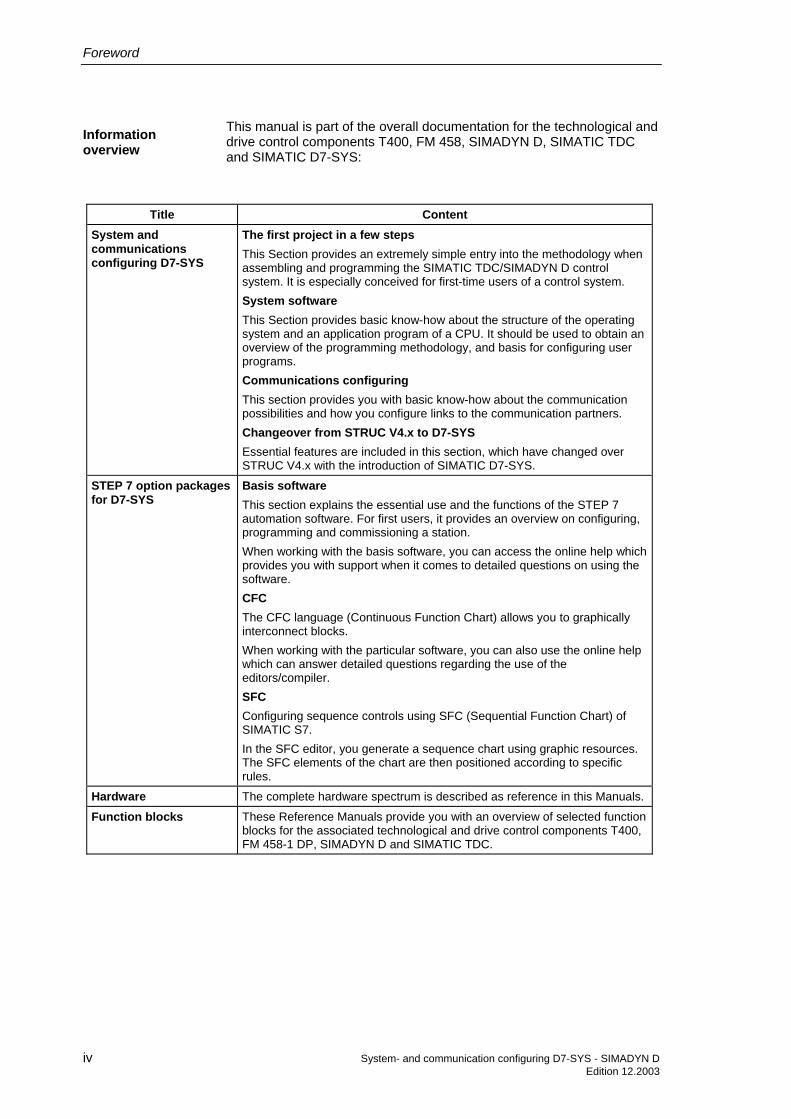
This manual is part of the overall documentation for the technological and drive control components T400, FM 458, SIMADYN D, SIMATIC TDC and SIMATIC D7-SYS:
Title Content System and communications configuring D7-SYS
The first project in a few steps This Section provides an extremely simple entry into the methodology when assembling and programming the SIMATIC TDC/SIMADYN D control system. It is especially conceived for first-time users of a control system. System software This Section provides basic know-how about the structure of the operating system and an application program of a CPU. It should be used to obtain an overview of the programming methodology, and basis for configuring user programs. Communications configuring This section provides you with basic know-how about the communication possibilities and how you configure links to the communication partners. Changeover from STRUC V4.x to D7-SYS Essential features are included in this section, which have changed over STRUC V4.x with the introduction of SIMATIC D7-SYS.
STEP 7 option packages for D7-SYS
Basis software This section explains the essential use and the functions of the STEP 7 automation software. For first users, it provides an overview on configuring, programming and commissioning a station. When working with the basis software, you can access the online help which provides you with support when it comes to detailed questions on using the software. CFC The CFC language (Continuous Function Chart) allows you to graphically interconnect blocks. When working with the particular software, you can also use the online help which can answer detailed questions regarding the use of the editors/compiler. SFC Configuring sequence controls using SFC (Sequential Function Chart) of SIMATIC S7. In the SFC editor, you generate a sequence chart using graphic resources. The SFC elements of the chart are then positioned according to specific rules.
Hardware The complete hardware spectrum is described as reference in this Manuals.
Function blocks These Reference Manuals provide you with an overview of selected function blocks for the associated technological and drive control components T400, FM 458-1 DP, SIMADYN D and SIMATIC TDC.
Information overview

Foreword
System- and communication configuring D7-SYS - SIMADYN D v Edition 12.2003
As first time user, we recommend that this Manual is used as follows:
• Please read the first section on using the software in order to get to know some of the terminology and basic procedure.
• Then use the particular sections of the Manual if you wish to carry-out certain processing steps (e.g. loading programs).
If you have already executed a small project, and have gained some experience, then you can read individual sections of the Manual in order to get up to speed about a specific subject.
Can be accessed globally at any time of the day:
Europe / Africa (Nuremberg) Technical Support Local time: Mon.-Fri. 7:00 to 17:00 Tel.: +49 (0)180 5050-222 Fax: +49 (0)9131 98-1603, +49 (0)911 895-7001 or +49 (0)180 5050-223 E-Mail: [email protected] GMT: +1:00
Europe / Africa (Nuremberg) Authorization Local time: Mon.-Fri. 7:00 to 17:00 Tel.: +49 (0)911 895-7200 Fax: +49 (0)911 895-7201 E-Mail: [email protected] GMT: +1:00
America (Johnson City) Technical Support and Authorization Local time: Mon.-Fri. 8:00 to 19:00 Tel.: +1 (0)770 740-3505 only toll-free from the US: +1 (0)800 241-4453 Fax: +1 (0)770 740-3699 E-Mail: [email protected]: -5:00
Asia / Australia (Singapore) Technical Support and Authorization Local time: Mon.-Fri. 8:30 to 17:30 Tel.: +65 740-7000 Fax: +65 740-7001 E-Mail: [email protected] [email protected] GMT: +8:00
Guide
Automation and Drives, Service & Support

Foreword
vi System- and communication configuring D7-SYS - SIMADYN D Edition 12.2003

System- and communication configuring D7-SYS - SIMADYN D vii Edition 12.2003
Contents
Foreword ........................................................................................................................................ iii
1 In just a few steps to the first project .................................................................................. 1-1 1.1 Prerequisites.......................................................................................................... 1-2 1.1.1 Software and hardware.......................................................................................... 1-2 1.1.2 What you can expect ............................................................................................. 1-4 1.2 Creating a new project........................................................................................... 1-5 1.3 Defining the hardware............................................................................................ 1-5 1.4 Generating a CFC chart......................................................................................... 1-6 1.4.1 Generating a new chart ......................................................................................... 1-6 1.4.2 Inserting, parameterizing and inter-connecting function blocks ............................ 1-6 1.5 Testing, compiling and downloading the project ................................................. 1-10 1.5.1 Checking the project consistency and compiling................................................. 1-10 1.5.2 Downloading the user project into the SIMADYN D-CPU module ...................... 1-10 1.6 Testing the user project ....................................................................................... 1-12 1.6.1 Disconnecting the connection online ................................................................... 1-13 1.6.2 Generating a connection online........................................................................... 1-13 1.6.3 Changing the parameterization online................................................................. 1-13 1.6.4 Inserting a block online ........................................................................................ 1-13 1.6.5 Deleting blocks online.......................................................................................... 1-13 1.7 Results ................................................................................................................. 1-14 1.8 Archiving the project ............................................................................................ 1-14
2 Systemsoftware...................................................................................................................... 2-1 2.1 Configuring............................................................................................................. 2-2 2.1.1 General description................................................................................................ 2-2 2.1.1.1 Configuring tools.................................................................................................... 2-2 2.1.1.2 Configuring steps................................................................................................... 2-3 2.1.1.3 Terminology and libraries ...................................................................................... 2-3 2.1.2 Configuring the hardware ...................................................................................... 2-4 2.1.2.1 The first step: Selecting the hardware modules .................................................... 2-4 2.1.2.2 The second step: Parameterizing the hardware modules..................................... 2-5 2.1.2.3 The third step: Checking the configuring............................................................... 2-7 2.1.3 Creating CFC charts .............................................................................................. 2-7 2.1.3.1 The first step: Selecting the function blocks .......................................................... 2-7 2.1.3.2 The second step: Parameterizing and interconnecting function blocks ................ 2-8 2.1.3.3 The third step: Compiling and loading the user program into the CPU............... 2-13

Contents
viii System- and communication configuring D7-SYS - SIMADYN D Edition 12.2003
2.1.4 Operating statuses of a CPU module ..................................................................2-14 2.1.5 Configuring example of a CPU module ...............................................................2-15 2.1.5.1 Task .....................................................................................................................2-15 2.1.5.2 Solution ................................................................................................................2-15 2.1.6 Description and use of the signal transfer mechanisms......................................2-17 2.1.6.1 Data consistency..................................................................................................2-17 2.1.6.2 Data transfer within the same task of a CPU.......................................................2-18 2.1.6.3 Data transfer between various CPU tasks...........................................................2-18 2.1.6.4 Data transfer between cyclic tasks of several CPUs...........................................2-19 2.1.6.5 Data transfer between interrupt tasks of several CPUs ......................................2-20 2.1.6.6 Minimizing the deadtimes ....................................................................................2-21 2.1.6.7 Processing sequence within a basic CPU clock cycle ........................................2-21 2.1.6.8 Interconnection changes and limited number of interconnections ......................2-21 2.1.7 Significance and uses of the process image .......................................................2-23 2.1.7.1 Implementing the process image.........................................................................2-24 2.1.7.2 Process image for cyclic tasks.............................................................................2-25 2.1.7.3 Process image for interrupt tasks ........................................................................2-26 2.1.8 Significance and application of the CPU synchronization ...................................2-27 2.1.8.1 Time synchronization ...........................................................................................2-27 2.1.8.2 Synchronizing its own basic clock cycle to the basic clock cycle of a master
CPU......................................................................................................................2-27 2.1.8.3 Synchronizing its own basic clock cycle to an interrupt task of a master CPU ...2-28 2.1.8.4 Synchronizing its own interrupt tasks to interrupt tasks of a master CPU...........2-28 2.1.8.5 Synchronizing several SIMATIC TDC/SIMADYN D stations...............................2-28 2.1.8.6 Response when the synchronization fails ...........................................................2-28 2.1.8.7 Configuring the CPU basic clock cycle synchronization......................................2-28 2.1.8.8 Configuring the interrupt task synchronization ....................................................2-30 2.1.8.9 Example of a synchronization configuration ........................................................2-31 2.1.9 Significance of the processor utilization ..............................................................2-31 2.1.9.1 Determining the approximate processor utilization..............................................2-31 2.1.9.2 Calculating the precise processor utilization .......................................................2-32 2.1.9.3 Mode of operation of the task administrator ........................................................2-32 2.1.9.4 Eliminating cycle errors........................................................................................2-34 2.1.10 Technical data of the operating system...............................................................2-34 2.1.10.1 Features ...............................................................................................................2-34 2.1.10.2 The basic operating system functions .................................................................2-36 2.1.10.3 The service utility .................................................................................................2-39 2.2 Function description and user instructions ..........................................................2-41 2.2.1 Fatal system error "H"..........................................................................................2-41 2.2.2 Background processing .......................................................................................2-43 2.2.2.1 Online test mode..................................................................................................2-44 2.3 System chart @SIMD ..........................................................................................2-45
3 Communications configuring ............................................................................................... 3-1 3.1 Introduction ............................................................................................................ 3-2 3.1.1 Basic information on communications ................................................................... 3-2 3.1.1.1 Overview of the various data couplings ................................................................. 3-2 3.1.2 Overview of the communication utilities................................................................. 3-8 3.1.3 Communication block I/Os..................................................................................... 3-9 3.1.3.1 Initialization input CTS ........................................................................................... 3-9

Contents
System- and communication configuring D7-SYS - SIMADYN D ix Edition 12.2003
3.1.3.2 Address connections AT, AR and US.................................................................. 3-10 3.1.3.3 Data transfer mode, MOD input........................................................................... 3-11 3.1.3.4 Firmware status, ECL, ECO connection.............................................................. 3-15 3.1.3.5 Status display, output YTS .................................................................................. 3-15 3.1.4 Mode of operation of the couplings ..................................................................... 3-16 3.1.4.1 Central coupling blocks........................................................................................ 3-17 3.1.4.2 Transmitters and receivers .................................................................................. 3-18 3.1.4.3 Compatible net data structures............................................................................ 3-19 3.1.4.4 Number of coupling modules in a subrack .......................................................... 3-20 3.1.4.5 Reorganizing a data interface.............................................................................. 3-20 3.2 Couplings on the subrack .................................................................................... 3-22 3.2.1 Local CPU coupling ............................................................................................. 3-22 3.2.2 Communications buffer coupling ......................................................................... 3-22 3.2.3 Coupling to EP3 modules .................................................................................... 3-23 3.3 Subrack coupling ................................................................................................. 3-25 3.3.1 Hardware structure .............................................................................................. 3-27 3.3.2 Scope of supply ................................................................................................... 3-27 3.3.3 Response when "shutting down" a coupling partner ........................................... 3-27 3.3.4 Response when "powering-up" the master subrack............................................ 3-28 3.3.4.1 Acknowledging..................................................................................................... 3-28 3.3.5 Restart frequency ................................................................................................ 3-29 3.3.6 Configuring........................................................................................................... 3-30 3.4 Industrial Ethernet coupling (SINEC H1) ............................................................. 3-31 3.4.1 Hardware and central coupling block .................................................................. 3-32 3.4.1.1 Hardware ............................................................................................................. 3-32 3.4.1.2 Central coupling block @CSH11......................................................................... 3-34 3.4.2 Communications via SINEC H1 layer 2............................................................... 3-34 3.4.3 Communications via SINEC H1 layer 4............................................................... 3-36 3.4.4 Communications via SINEC H1 layer 7 (STF)..................................................... 3-38 3.4.4.1 Address connections ........................................................................................... 3-38 3.4.4.2 Communications utility, process data .................................................................. 3-40 3.4.4.3 Communications utility, message system............................................................ 3-42 3.4.5 System time ......................................................................................................... 3-44 3.4.6 Data quantities, sampling times........................................................................... 3-44 3.4.7 NML network management.................................................................................. 3-45 3.5 PROFIBUS DP coupling ...................................................................................... 3-46 3.5.1 Configuring with D7-SYS..................................................................................... 3-47 3.5.1.1 Central coupling block ......................................................................................... 3-47 3.5.1.2 Address connections AT, AR............................................................................... 3-48 3.5.1.3 SYNC/FREEZE commands ................................................................................. 3-49 3.5.1.4 Configuring versions of SYNC/FREEZE.............................................................. 3-50 3.5.1.5 Diagnostics function block ................................................................................... 3-54 3.5.2 Configuring with COM PROFIBUS ...................................................................... 3-58 3.5.2.1 Harmonizing with data configured in CFC........................................................... 3-58 3.5.2.2 SS52 as PROFIBUS slave .................................................................................. 3-59 3.5.2.3 Loading the database .......................................................................................... 3-60 3.5.3 Start-up/diagnostics ............................................................................................. 3-61 3.5.3.1 LEDs .................................................................................................................... 3-61

Contents
x System- and communication configuring D7-SYS - SIMADYN D Edition 12.2003
3.5.3.2 Error class (ECL) and error code (ECO) .............................................................3-62 3.5.3.3 Application example, PROFIBUS DP coupling....................................................3-63 3.5.3.4 Typical configuration and system requirements ..................................................3-64 3.5.3.5 Check list of the required hardware and software components for
SIMADYN D .........................................................................................................3-66 3.5.3.6 Configuring under STEP 7 CFC ..........................................................................3-67 3.5.3.7 Using transmit- and receive blocks......................................................................3-69 3.5.3.8 Configuring the typical configuration in CFC .......................................................3-70 3.5.3.9 Configuring the SS52 communications module with COM PROFIBUS ..............3-73 3.5.3.10 Generating the COM database with COM PROFIBUS .......................................3-73 3.5.3.11 Downloading the COM database into the SS52 ..................................................3-81 3.5.3.12 Working with the "SS52load" download tool........................................................3-81 3.5.3.13 Behavior of the SS52 during and after the download ..........................................3-81 3.6 PROFIBUS FDL coupling (SINEC L2 FDL).........................................................3-83 3.6.1 Hardware and central coupling block ..................................................................3-83 3.6.1.1 Hardware for PROFIBUS FDL.............................................................................3-83 3.6.1.2 Central coupling block @CSL2L for the PROFIBUS FDL coupling ....................3-84 3.6.1.3 Communications via PROFIBUS FDL .................................................................3-85 3.6.2 Data quantities, sampling times...........................................................................3-87 3.7 PROFIBUS FMS coupling (SINEC L2-FMS) .......................................................3-88 3.7.1 Hardware and central coupling block ..................................................................3-90 3.7.1.1 Hardware for the PROFIBUS FMS coupling .......................................................3-90 3.7.1.2 Central coupling block @CSL2F for PROFIBUS FMS coupling..........................3-90 3.7.2 Communications via PROFIBUS FMS ................................................................3-91 3.7.3 SIMADYN D communications utility.....................................................................3-94 3.7.3.1 Process data ........................................................................................................3-94 3.7.3.2 Message system..................................................................................................3-98 3.7.4 Tables ................................................................................................................3-100 3.7.4.1 Address parameters, FMS utilities.....................................................................3-100 3.7.5 Data quantities, sampling times.........................................................................3-102 3.7.6 COMSS5............................................................................................................3-102 3.7.6.1 Menu structure ...................................................................................................3-103 3.7.6.2 Bus parameters..................................................................................................3-104 3.7.6.3 Communication associations .............................................................................3-106 3.7.6.4 Loading the database ........................................................................................3-116 3.7.7 Examples ...........................................................................................................3-118 3.7.7.1 Example 1: Process data between two SIMADYN D stations...........................3-118 3.7.7.2 Example 2: Process data between three SIMADYN D stations ........................3-122 3.8 DUST1 coupling.................................................................................................3-127 3.8.1 Hardware structure ............................................................................................3-127 3.8.2 Configuring.........................................................................................................3-127 3.8.3 Configuring example, service to CFC................................................................3-128 3.8.4 Configuring example, process data between SIMADYN D subracks................3-128 3.8.4.1 Subrack 1...........................................................................................................3-128 3.8.4.2 Subrack 2...........................................................................................................3-129 3.9 DUST2 coupling.................................................................................................3-131 3.9.1 Hardware structure ............................................................................................3-131 3.9.2 Configuring.........................................................................................................3-131

Contents
System- and communication configuring D7-SYS - SIMADYN D xi Edition 12.2003
3.10 DUST3 coupling................................................................................................. 3-133 3.10.1 Hardware structure ............................................................................................ 3-133 3.10.2 Configuring......................................................................................................... 3-133 3.10.2.1 Data entries at inputs AT, AR ............................................................................ 3-133 3.10.2.2 Central coupling block ....................................................................................... 3-134 3.10.2.3 Transmit/receive blocks ..................................................................................... 3-135 3.11 DUST7 coupling................................................................................................. 3-136 3.11.1 General .............................................................................................................. 3-136 3.11.2 Hardware ........................................................................................................... 3-136 3.11.3 Configuring......................................................................................................... 3-136 3.12 MPI coupling ...................................................................................................... 3-137 3.12.1 Characteristics and hardware............................................................................ 3-137 3.12.2 Configuring......................................................................................................... 3-137 3.13 USS master coupling ......................................................................................... 3-138 3.13.1 Hardware structure ............................................................................................ 3-138 3.13.2 Data transfer technique ..................................................................................... 3-141 3.13.3 Transferred net data .......................................................................................... 3-141 3.13.4 Configuring......................................................................................................... 3-141 3.13.4.1 Central coupling block @CSU........................................................................... 3-141 3.13.4.2 Function blocks which can be used................................................................... 3-142 3.13.4.3 Telegram types .................................................................................................. 3-143 3.13.5 Mode of operation.............................................................................................. 3-143 3.13.6 USS master on the T400 technology module.................................................... 3-144 3.13.6.1 Basis network for the T400 technology module ................................................ 3-144 3.13.6.2 Initialization ........................................................................................................ 3-145 3.13.6.3 Broadcast........................................................................................................... 3-145 3.13.7 Literature............................................................................................................ 3-145 3.14 USS slave coupling............................................................................................ 3-146 3.14.1 Basis network for the T400 technology module ................................................ 3-146 3.14.2 Initialization ........................................................................................................ 3-146 3.14.3 Exchanging process data .................................................................................. 3-147 3.14.3.1 Transmitting ....................................................................................................... 3-147 3.14.3.2 Receiving ........................................................................................................... 3-147 3.14.4 Handling and visualizing parameters................................................................. 3-148 3.14.5 Special features for 4-conductor operation of the USS-slave coupling............. 3-148 3.14.6 USS-slave coupling via V24/RS232 .................................................................. 3-148 3.15 Peer-to-peer coupling ........................................................................................ 3-149 3.15.1 Initialization ........................................................................................................ 3-149 3.15.2 Transferring process data.................................................................................. 3-149 3.15.2.1 Transmitting ....................................................................................................... 3-149 3.15.2.2 Receiving ........................................................................................................... 3-150 3.16 SIMATIC P-bus coupling ................................................................................... 3-151 3.16.1 Overview of the 3 data transfer types, FM 458 ←→ SIMATIC-CPU................. 3-152 3.16.2 Initiating a process interrupt on SIMATIC-CPU................................................. 3-153 3.16.3 Data transfer via I/O accesses .......................................................................... 3-154

Contents
xii System- and communication configuring D7-SYS - SIMADYN D Edition 12.2003
3.16.4 Transferring data sets ........................................................................................3-156 3.17 SIMOLINK drive coupling...................................................................................3-160 3.17.1 Basic information ...............................................................................................3-160 3.17.2 Application with master-slave process data transfer .........................................3-162 3.17.3 Applications and modes which should be set....................................................3-163 3.17.4 Configuring - first steps......................................................................................3-166 3.17.4.1 Configuring the SIMOLINK coupling under STEP 7 ..........................................3-167 3.17.4.2 SIMOLINK function blocks.................................................................................3-171 3.17.4.3 Parameterizing the MASTERDRIVES MC.........................................................3-172 3.17.5 Coupling diagnostics..........................................................................................3-174 3.17.6 Options and accessories ...................................................................................3-176 3.18 Table function ....................................................................................................3-177 3.18.1 Introduction ........................................................................................................3-177 3.18.1.1 Overview, "Manual mode"..................................................................................3-178 3.18.1.2 Overview, "Automatic mode: Communications" ................................................3-178 3.18.1.3 Function block WR_TAB....................................................................................3-180 3.18.2 Manual mode .....................................................................................................3-182 3.18.2.1 Application..........................................................................................................3-182 3.18.2.2 Configuring.........................................................................................................3-183 3.18.3 Automatic mode: Communications ....................................................................3-184 3.18.3.1 Application with an S7 control and SIMATIC FM 458 application module ........3-184 3.18.3.2 Configuring for S7 control and SIMATIC FM 458 application module...............3-186 3.18.3.3 Inserting tabular values in the data block ..........................................................3-188 3.18.3.3.1 Manually entering tabular values .......................................................................3-188 3.18.3.3.2 Importing tabular values.....................................................................................3-192 3.18.3.3.3 Subsequently downloading tabular values into a DB ........................................3-202 3.18.3.4 Structure of the data telegram for TCP/IP or DUST1 connection......................3-204 3.18.4 Automatic mode: Memory card..........................................................................3-205 3.18.4.1 Generating a table file in the csv format ............................................................3-205 3.18.4.2 Working with the D7-SYS additionalComponentBuilder....................................3-207 3.18.4.3 Downloading ......................................................................................................3-210 3.18.4.4 Configuring the function blocks..........................................................................3-212 3.19 Parameter access technique for D7-SYS..........................................................3-214 3.19.1 General description of the parameter functionalityinformation ..........................3-214 3.19.1.1 Parameters ........................................................................................................3-214 3.19.1.2 BICO technology for SIMADYN D .....................................................................3-217 3.19.1.3 Status-dependent parameter changes ..............................................................3-221 3.19.1.4 Identifying SIMADYN D components.................................................................3-221 3.19.1.5 Units and unit texts ............................................................................................3-222 3.19.2 Parameterizing on the Application module FM 458...........................................3-225 3.19.2.1 Terminology .......................................................................................................3-225 3.19.2.2 Communications behavior .................................................................................3-226 3.19.2.3 Generating the hardware configuration .............................................................3-226 3.19.2.4 Functional scope................................................................................................3-227 3.19.2.5 Operator devices which can be connected........................................................3-228 3.20 Communications utility, display control..............................................................3-229 3.20.1 General description............................................................................................3-229 3.20.2 Hardware ...........................................................................................................3-229 3.20.3 Software .............................................................................................................3-230

Contents
System- and communication configuring D7-SYS - SIMADYN D xiii Edition 12.2003
3.20.3.1 Central block @DIS ........................................................................................... 3-230 3.20.3.2 Process data acquisition blocks ........................................................................ 3-231 3.20.3.3 Acquisition blocks for binary values (only OP2) ................................................ 3-232 3.20.3.4 Message output blocks (only OP2).................................................................... 3-233 3.20.4 Application information ...................................................................................... 3-234 3.20.4.1 Computation times............................................................................................. 3-235 3.20.4.2 Data transfer times ............................................................................................ 3-235 3.20.5 Configuring example.......................................................................................... 3-236 3.21 Communications utility, message system.......................................................... 3-239 3.21.1 Entry logic of the message entry blocks ............................................................ 3-239 3.21.1.1 Message entry blocks for an activated message .............................................. 3-239 3.21.1.2 Message entry blocks for an activated and a de-activated message................ 3-240 3.21.2 Configuring example for a message system ..................................................... 3-240 3.21.3 Output formats of the message evaluation block MSI....................................... 3-244 3.21.3.1 Structure of an error- or alarm message ........................................................... 3-244 3.21.3.2 Overview of the message formats ..................................................................... 3-244 3.21.3.3 Structure of an overflow message ..................................................................... 3-246 3.21.3.4 Structure of a communications error message.................................................. 3-246 3.21.3.5 System error message structure ....................................................................... 3-247 3.21.3.6 Detailed description of the message formats of function block MSI.................. 3-247 3.21.3.7 Output format of the message evaluation block MSPRI.................................... 3-251 3.22 Communications utility parameter processing................................................... 3-254 3.22.1 Master configuring ............................................................................................. 3-254 3.22.1.1 Description of scope .......................................................................................... 3-254 3.22.1.2 Supported couplings .......................................................................................... 3-255 3.22.1.3 Telegram structure............................................................................................. 3-255 3.22.1.4 Mode of operation of the PKW blocks ............................................................... 3-255 3.22.1.5 Configuring example.......................................................................................... 3-257 3.22.1.6 Task/response IDs............................................................................................. 3-260 3.22.1.7 Task/response assignments.............................................................................. 3-262 3.22.1.8 Cascading.......................................................................................................... 3-262 3.22.1.9 Parameter change report processing ................................................................ 3-263 3.22.1.10 Cyclic tasks ........................................................................................................ 3-263 3.22.1.11 Temporary error messages from the DPI blocks............................................... 3-263 3.22.1.12 Important drive converter settings ..................................................................... 3-264 3.23 For change tasks, the parameter change rights of the drive converter must be
set at the configured interface. Network ............................................................ 3-265 3.23.1 Terminology ....................................................................................................... 3-265 3.23.2 Description......................................................................................................... 3-265 3.23.3 Rigid network ..................................................................................................... 3-266 3.23.3.1 Address data in the rigid network ...................................................................... 3-266 3.23.3.2 Assigning the data interfaces to the configured NTCs ...................................... 3-268 3.23.3.3 Assigning the copying relationships of the NTC to NTD ................................... 3-269 3.23.3.4 Route selection and errors ................................................................................ 3-269 3.23.3.5 Initialization of a rigid network............................................................................ 3-269 3.23.3.6 Channel modes.................................................................................................. 3-269 3.24 Communications utility process data ................................................................. 3-270 3.24.1 Receive- and transmit blocks ............................................................................ 3-270 3.24.1.1 Virtual connections ............................................................................................ 3-270 3.24.1.2 I/O of the CRV, CTV blocks ............................................................................... 3-274

Contents
xiv System- and communication configuring D7-SYS - SIMADYN D Edition 12.2003
3.24.2 Channel marshalling blocks CCC4 and CDC4..................................................3-274 3.24.2.1 Group block CCC4.............................................................................................3-274 3.24.2.2 Distribution block CDC4.....................................................................................3-275 3.24.2.3 Compatible net data structure............................................................................3-276 3.24.3 Diagnostic outputs .............................................................................................3-276 3.24.3.1 Fault/error cause................................................................................................3-276 3.24.3.2 Channel assignment ..........................................................................................3-277 3.24.3.3 Channel statuses ...............................................................................................3-278 3.24.4 Introduction – "Pointer-based communication blocks" ......................................3-278 3.24.4.1 Principle mode of operation ...............................................................................3-279 3.24.4.2 Applications........................................................................................................3-279 3.24.4.3 Features of pointer-based communications ......................................................3-280 3.24.4.4 Associated function blocks ................................................................................3-281 3.24.4.5 Pointer interface.................................................................................................3-281 3.24.4.6 Configuring information and instructions ...........................................................3-282 3.24.4.7 Examples of CFC screenshots ..........................................................................3-282 3.25 Communications utility service ..........................................................................3-288 3.25.1 Function block SER ...........................................................................................3-289 3.25.2 System load, response times.............................................................................3-290 3.26 Communications utility time of day synchronization ..........................................3-291 3.27 Communications with SIMATIC Operator Panels..............................................3-292 3.27.1 Configuring example ..........................................................................................3-292 3.27.2 Configuring SIMADYN D....................................................................................3-293 3.27.2.1 Selecting the components in HWConfig ............................................................3-293 3.27.2.2 Configuring with CFC.........................................................................................3-294 3.27.2.2.1 Initializing the OP7 .............................................................................................3-295 3.27.2.2.2 Reading function block connections (I/O)..........................................................3-295 3.27.2.2.3 Writing function block connections ....................................................................3-296 3.27.2.2.4 Configuring events .............................................................................................3-297 3.27.2.2.5 Configuring alarm messages .............................................................................3-298 3.27.2.2.6 Configuring the function keyboard .....................................................................3-299 3.27.2.2.7 Configuring the interface area ...........................................................................3-300 3.27.2.3 Importing the symbol table.................................................................................3-301 3.27.3 Configuring the OP7 with ProTool/Lite ..............................................................3-302 3.27.4 Application information.......................................................................................3-303 3.27.4.1 Computation times .............................................................................................3-303 3.28 Communications with WinCC (MPI) ..................................................................3-304 3.29 Communications with WinCC (SINEC H1) ........................................................3-306 3.29.1 Prerequisites ......................................................................................................3-306 3.29.2 Process variables...............................................................................................3-307 3.29.2.1 SIMADYN D software ........................................................................................3-307 3.29.2.2 Configuring WinCC ............................................................................................3-310 3.29.3 Binary events .....................................................................................................3-310 3.29.4 SIMADYN D messages......................................................................................3-310 3.29.4.1 SIMADYN D configuring software......................................................................3-310 3.29.4.2 WinCC configuring software ..............................................................................3-312 3.29.5 Generating the address book using the CFC editor ..........................................3-312 3.29.6 NML configuring software for CSH11 ................................................................3-313

Contents
System- and communication configuring D7-SYS - SIMADYN D xv Edition 12.2003
3.29.7 Address list import tool ADRIMP ....................................................................... 3-314 3.29.7.1 Prerequisites...................................................................................................... 3-314 3.29.7.1.1 Generating the variable definition file ................................................................ 3-315 3.29.7.1.2 Generating and importing a new signal list........................................................ 3-315 3.29.7.1.3 Importing an existing signal list.......................................................................... 3-316 3.29.7.2 Checking the generated tag management in WinCC........................................ 3-316 3.29.8 Communications set-up, SIMADYN D-WinCC .................................................. 3-316 3.29.8.1 Connecting cable ............................................................................................... 3-316 3.29.8.2 Activating WinCC............................................................................................... 3-317 3.29.8.3 Activating SIMADYN D ...................................................................................... 3-317
4 Changeover from STRUC V4.x to D7-SYS ........................................................................... 4-1 4.1 Function blocks...................................................................................................... 4-2 4.1.1 Assigning names to function block types and connections ................................... 4-2 4.1.2 Control blocks ........................................................................................................ 4-3 4.1.3 Arithmetic blocks.................................................................................................... 4-4 4.1.4 Logic blocks ........................................................................................................... 4-5 4.1.5 Input/output blocks................................................................................................. 4-8 4.1.6 Communication blocks........................................................................................... 4-9 4.1.7 Conversion blocks ............................................................................................... 4-13 4.1.8 Diagnostic blocks................................................................................................. 4-14 4.1.9 SIMOVERT D block ............................................................................................. 4-14 4.1.10 COROS blocks .................................................................................................... 4-15 4.2 Adapting specific connection attributes ............................................................... 4-16 4.2.1 Display utility ........................................................................................................ 4-16 4.2.2 Equipment response utility................................................................................... 4-17 4.2.3 Changing the data types for function blocks ....................................................... 4-17 4.3 Hardware differences........................................................................................... 4-18 4.4 Communications .................................................................................................. 4-20 4.5 Configuring........................................................................................................... 4-21 4.5.1 Configuring tools.................................................................................................. 4-21 4.5.2 Object-oriented handling of the configuring tools ................................................ 4-22 4.5.3 Installation and de-installation ............................................................................. 4-22 4.6 Configuring, step by step ..................................................................................... 4-25 4.6.1 Administering the project data ............................................................................. 4-25 4.6.2 Configuring the hardware .................................................................................... 4-25 4.6.3 Configuring the open-loop/closed-loop control.................................................... 4-27 4.6.4 Compiling and loading the user program............................................................. 4-30 4.6.5 Test and start-up.................................................................................................. 4-31 4.7 V4.x terminology which is replaced by D7-SYS terminology............................... 4-33
5 Closed-loop thyristor current control .................................................................................. 5-1 5.1 Overview ................................................................................................................ 5-2 5.1.1 Hardware configuration.......................................................................................... 5-3

Contents
xvi System- and communication configuring D7-SYS - SIMADYN D Edition 12.2003
5.1.2 Software configuration ........................................................................................... 5-4 5.2 Function description............................................................................................... 5-6 5.2.1 PA6, synchronization ............................................................................................. 5-6 5.2.1.1 Offset angle............................................................................................................ 5-8 5.2.1.2 Line supply analysis / rotating field detection ........................................................ 5-9 5.2.1.3 Synchronization and pulse generation ................................................................5-12 5.2.2 EMF, voltage - actual value sensing....................................................................5-15 5.2.3 SOL, switch-over logic .........................................................................................5-19 5.2.3.1 Fault evaluation and protection............................................................................5-25 5.2.4 CAV, current actual value sensing.......................................................................5-30 5.2.5 CSP, current setpoint calculation.........................................................................5-34 5.2.6 CPC, current pre-control ......................................................................................5-36 5.2.7 CPI, current controller ..........................................................................................5-38 5.2.8 PC6, firing angle controller ..................................................................................5-42 5.2.9 FCS, field current setpoint output ........................................................................5-47 5.3 Commissioning ....................................................................................................5-51 5.3.1 Preparatory work..................................................................................................5-51 5.3.2 Entering the characteristic system quantities ......................................................5-52 5.3.3 Current sensing calibration ..................................................................................5-55 5.3.4 Voltage sensing calibration..................................................................................5-56 5.3.5 Determining the offset angle................................................................................5-56 5.3.6 Determining the armature time constant TA........................................................5-57 5.3.7 Optimizing the current controller..........................................................................5-59 5.3.8 Field supply..........................................................................................................5-61 5.4 Special features/issues........................................................................................5-63 5.4.1 Operation from 60 [Hz] line supplies....................................................................5-63 5.4.2 Operation with unstable line supplies ..................................................................5-63 5.4.3 Communications utility, time synchronization......................................................5-64 5.5 Interfaces to the power electronics ......................................................................5-65 5.5.1 SITOR set ............................................................................................................5-65 5.5.2 SITOR cabinet .....................................................................................................5-67 5.6 Definitions ............................................................................................................5-74 5.6.1 Formats ................................................................................................................5-74 5.6.2 Designations ........................................................................................................5-75 5.7 Abbreviations .......................................................................................................5-76 5.8 Appendix ..............................................................................................................5-77 5.8.1 Standard configuration of parameters .................................................................5-77 5.8.2 Standard connections ..........................................................................................5-81 5.8.3 Configuring example for normalization ................................................................5-82 5.8.3.1 Representation with normalized values...............................................................5-82 5.8.3.2 Representation with absolute values...................................................................5-83
Index .............................................................................................................................................. I-1

System- and communication configuring D7-SYS - SIMADYN D 1-1Edition 12.2001
1 In just a few steps to the first project
1.1 Prerequisites 1-2
1.2 Creating a new project 1-5
1.3 Defining the hardware 1-5
1.4 Generating a CFC chart 1-6
1.5 Testing, compiling and downloading the project 1-10
1.6 Testing the user project 1-12
1.7 Results 1-14
1.8 Archiving the project 1-14
Section overview

In just a few steps to the first project
1-2 System- and communication configuring D7-SYS - SIMADYN DEdition 12.2001
1.1 Prerequisites
These brief instructions are intended for introductory level personnel andit outlines the basic procedure when generating a project.
More detailed information about the dialog boxes of the developmentsoftware and their processing is provided in the corresponding onlinehelp.
1.1.1 Software and hardware
Three software packages
• STEP 7
• CFC
• D7-SYS
must be installed precisely in this sequence on your PG/PC withWindows 95/98/ME/NT 4.0/2000. Authorization is required for STEP7 andCFC.
NOTE The installation and user instructions are provided in the particular"readme" files. Please observe the interdependencies betweenversions!
When installing STEP7, you will be prompted for the online interface,however, for SIMADYN D nothing has to be selected and installed.("Close" window and exit the following window with "OK".)
You will require the following hardware components for the "My FirstProject” project example:
Components Function Diagram/Order No.SR6 subrack with power supply6 slots, backplane PC board withL bus, without fan
... if the subrack is for aSIMADYN D station.... it is used to mechanicallyaccommodate the modules andsupply them with power.
6DD1682-0BB0CPU module PM5(at slot 1)
... executes the user program.
... exchanges data with othermodules via the backplane PCboard of the subrack.... communicates with a PG/PCvia the serial interface.
6DD1600-0AJ0
Introduction
Software
Hardware

In just a few steps to the first project
System- and communication configuring D7-SYS - SIMADYN D 1-3Edition 12.2001
MS5 program memory module(for PM5)PC card standard,2 Mbyte flash memory and8 Kbyte EEPROM
... saves the operating system,the user program and the onlinechanges.
6DD1610-0AH0PC cable SC 57Zero-modem cable
... connects the CPU module tothe PG/PC.
6DD1684-0FH0Expansion module IT41(at slot 2)16 digital inputs and outputs,8 analog inputs and outputs,4 incremental encoder inputs.
... expands the CPU module bytechnology-specific functions. It isespecially fast, as it is directlyscrewed to the CPU module andthe backplane bus is not used.
6DD1606-3AC0Interface cable SC 54Length: 2 m
... connects the inputs/outputs ofthe IT41 module with up to 5SBxx or SU12 interface modules.
6DD1684-0FE0Interface module SB102 x 8 screw terminals,LED displays
... allows you to test the userprogram during commissioningand in operation, as the statusesof the digital outputs aredisplayed using LEDs.
6DD1681-0AE2Fig. 1-1 Module list for the project example "My First Project”
NOTE It is also possible to use other hardware platforms (T400, FM 458) byappropriately taking this into account in the configuring.Technical data is provided in the SIMADYN D Hardware Manual,additional ordering information in Catalog DA99.

In just a few steps to the first project
1-4 System- and communication configuring D7-SYS - SIMADYN DEdition 12.2001
1.1.2 What you can expect
The example "My First Project” guides you step-by-step to a projectwhich can actually run.
1. Analyze the particular taskThis allows you to identify the function blocks, inputs and outputswhich you require and which hardware:
2. Define the hardwareYou will use this hardware information in STEP7 in order to enter themodules and define your particular properties.
3. Configure and compileYou generate the configured software in CFC using the functionblocks and compile this. You can configure the hardware after all ofthe checks have been made.
4. Test the configuring softwareYou can now run the program, tested online and change it on theSIMADYN D modules.
5. Archive the project
You can subsequently apply this procedure for you own applications.
The task comprises two sections:
1. A sawtooth generator with a fixed frequency, outputs its value via aD/A converter.
2. Running Lights with 8 channels.
To start off with, define the individual functions for the appropriate sub-tasks and define the necessary hardware:
1. Sawtooth generator
A sawtooth waveform is generated by an integrator, which resets itselfafter an upper limit has been exceeded. The integrator value is outputvia an analog output.
2. Running light
Eight comparators compare the sawtooth value with constant values.The results are output through digital outputs and control the LEDs onthe interface module.
The running light has the following phases:
• All of the LEDs are dark.
• The LEDs are switched bright and then dark again so that only oneis bright at any one time.
From the task tothe first project
The task

In just a few steps to the first project
System- and communication configuring D7-SYS - SIMADYN D 1-5Edition 12.2001
1.2 Creating a new project
Step Procedure Result1
Double-click on the symbol .(if the STEP 7 Assistant starts, cancel this.)
The SIMATIC Manager is opened.
2 SelectFile > New.Enter "My First Project“into the dialog box, Project.In the dialog box, select the path„LW:\Siemens\Step7\S7proj“.Click on OK. Your new project is displayed.
3 SelectInsert > Station > SIMADYN D station.
The "SIMADYN D station“ hardware objectis inserted.
1.3 Defining the hardware
The SIMADYN D subrack structure is entered in STEP 7(HW Config).
Step Procedure Result4 Select the hardware object
"SIMADYN D station“ and selectEdit > Open object. HW Config is called-up.
5 Open it, if required, the hardware catalogwith View > Catalog.
The hardware catalog with all of the availablefamily of modules is opened.
6 Select the SR6 from theSIMADYN D family of modules and CatalogSubracks and drag it to the (upper) window
The subrack is displayed with six slots.
7 Locate them one after the other>CPU Modules >PM5 at slot 1>Expansion Modules >IT41 at slot 2>Slot covers >SR81 at slots 3 to 6
The subrack is equipped.
8 Open the properties dialog box of the PM5CPU module withEdit > Object properties.
The PM5 dialog box with general moduleinformation and the setting registers foraddresses, basic clock cycle, cyclic tasksand interrupt tasks are displayed.
9 Select the basic sampling time T0 (in thiscase: 1 ms) under the basic clock cycle tab.Click on the cyclic tasks tab and set thesampling time T1 to 2 ms and T2 to 4 ms.Click on OK.
The required sampling times are entered.
The properties dialog box is closed.

In just a few steps to the first project
1-6 System- and communication configuring D7-SYS - SIMADYN DEdition 12.2001
10 Open the properties dialog box of moduleIT41 usingEdit > Object properties.
The IT41 dialog box with general moduleinformation and the setting tab for addressesis displayed.
11 Under the Addresses tab, click on the Pre-assign button.Click on OK.
All of the addresses are assigned symbolicnames for subsequent use in CFC charts.
12 Check your hardware withStation > Check consistency.
If fault/error-free, continue with Step 13,otherwise check the hardware configuration.
13 Compile your hardware configuration withStation > Save and compile.
The hardware has been fully configured.
1.4 Generating a CFC chart
1.4.1 Generating a new chart
Step Procedure Result14 Change into the SIMATIC Manager and open
the project tree up to the Charts object.Select the charts by clicking on them.
15 Generate a new CFC chart twice withInsert > S7 software > CFC .
The CFC 1 and CFC 2 charts are displayedas new objects at the righthand side of theproject window.
16 Select chart CFC2 in the project window andopen the properties dialog box withEdit > Object properties .Enter the "sawtooth generator" name.Click on OK.
You obtain the properties dialog box of theCNC chart.
The Properties dialog box is closed.
17 Repeat step 16 with the CFC2 chart and re-name it "Running lights".
The charts appear in the project windowunder their new name.
1.4.2 Inserting, parameterizing and inter-connecting function blocks
Step Procedure Result18 Select the "sawtooth generator“ chart and
open the "CFC Editor withEdit > Open object.
The CFC Editor is opened with the workingarea (>1 sheet) and the block catalog.(Catalog missing? Select View > Catalog)(>1 Sheet? Select View > Sheet view)
19 Open the family of blocks Closed-loopcontrol and drag the function block INT(integrator) to the working area.
The block is now located on the sheet andhas the ID for running in cyclic task T1.
20 Open the properties dialog box of functionblock INT with Edit > Object properties .
The INT dialog box with general blockinformation and the setting tab I/O appears.

In just a few steps to the first project
System- and communication configuring D7-SYS - SIMADYN D 1-7Edition 12.2001
21 Under the General tab, change the name to„sawtooth“.
22 Under the I/O tab, enter the values for theblock inputs, e.g.• X = 1• LU = 11250• TI = 5 msClick on OK. The Properties dialog box is closed and the
function block inputs now have valuesassigned.
23 First click on output QU and then on input S. The output QU (upper limit) is now coupledback to input S (set).
24 Select DAC (analog output) from the blockfamily ON/OFF and locate it next to functionblock INT.Open the dialog box using Edit > Objectproperties and change the name to "analogoutput“.Enter, for example under the I/O tab:• DM = 0• OFF= 0• SF = 1E6Click on OK.Select connection AD (hardware address),and call-up the dialog box to interconnect theobject withInsert > Connect to operand. Then markthe selection window. Select the first entryand click on OK
The block inputs are parameterized.
The hardware address of the first analogoutput channel is assigned.
25 In the "sawtooth“ block, click on output Yand after this on input X in the "analogoutput" block.
The sawtooth generator is connected to theanalog output.
All changes made in the CFC chart are immediately saved.
Proceed the same for the second sub-task (running lights) (from step 18).Change into the SIMATIC Manager, open the CFC chart "running lights"insert the function blocks into the CFC chart, parameterize and connectthem.All of the necessary information (number of blocks, types and blockparameters) can be taken from the following diagrams. Arrange the firstfunction block and all others, viaEdit > Run sequence in cyclic task T2. The connection between the"sawtooth" block and the comparators is realized by changing the CFCwindow (Window > ...).

In just a few steps to the first project
1-8 System- and communication configuring D7-SYS - SIMADYN DEdition 12.2001
Fig. 1-2 "Sawtooth generator“ chart

In just a few steps to the first project
System- and communication configuring D7-SYS - SIMADYN D 1-9Edition 12.2001
Fig. 1-3 "Running lights“ chart

In just a few steps to the first project
1-10 System- and communication configuring D7-SYS - SIMADYN DEdition 12.2001
1.5 Testing, compiling and downloading the project
1.5.1 Checking the project consistency and compiling
Step Procedure Result26 Start the consistency check of your project
withChart > Check consistency > Charts asprogram, then OK.Acknowledge the dialog window or evaluatethe error messages via Details.
The result is displayed in the dialog window.
27 Start to compile the project after a successfulconsistency check withChart > Compile > Charts as program,then OK.Acknowledge the dialog window or evaluatethe error messages using Details.
The result is displayed in a dialog window.
You have created your first user project.
1.5.2 Downloading the user project into the SIMADYN D-CPU module
SIMADYN D allows you to
• download online or• offline.
Maybe you do not have a connection from your PC/PG to the SIMADYND station, which is why you can use the possibility of downloading into amemory module.
Step Procedure Result28 Select Target system > Download. You will obtain a dialog window with options.
29 Select "User program" and "Offline"Insert the memory module into the PCMCIAslot of the PG/PC.Start to download with OK.
A progress display shows how the systemand your user program are beingdownloaded into the memory module.
30 Insert the memory module into the SIMADYND station and re-start it. Your user program is then started.
Introduction
Downloadingoffline

In just a few steps to the first project
System- and communication configuring D7-SYS - SIMADYN D 1-11Edition 12.2001
You have established a connection from your PC/PG to SIMADYN Dstation, and you can download the program memory module into the CPUmodule.
Step Procedure Result28 Check whether your SIMADYN D station
(hardware) is correctly configured,assembled and connected.
Observe the configuration instructions andconnection possibilities for the individualhardware components in the appropriatehardware documentation!
29 Insert the memory module into the CPUmodule and start the SIMADYN D station.
A flashing zero appears on the CPU moduledisplay
30 Install the interface between the SIMADYN Dstation and the PC in the SIMATIC Managerusing the menu command:Options > Set PG/PC interface....
You obtain a dialog window "Install/uninstallinterfaces" in which the various interfacesare listed.
31 In the dialog window, select "DUST1protocol” and install this protocol withInstallAcknowledge with "yes" and then close thedialog window.Select the interface used and acknowledgewith "OK".
You obtain a dialog window in which you candecide, by entering either"Yes" or "No" whether you wish toimmediately go online.The "Set PG interface dialog window" isdisplayed where you can select the accessroute "DUST1 (COM1)" or "DUST1 (COM2)".
32 Select theTarget system > Download.
You obtain the dialog window with options.
33 Select the "System and user program","Online (COM1)” and initialization when firstdownloading the user program.Note: If a user program is downloadedagain, you can also specify "User program"without "initialization".Start with "download"
A progress display shows how the systemand your user program are beingdownloaded into the memory module.If download has been completed, the dialogwindow "Operating status" is displayed withthe "STOP" status and a 1 is displayed onthe CPU module.
34 Start the SIMADYN D stationwith "Restart" and then select "Close".Note: If you use an SR6 subrack, then youmust manually initiate a restart using a"RESET" at the subrack.
Your user program is started and the"Operating status" dialog window isdisplayed with the "RUN" status.
Downloadingonline

In just a few steps to the first project
1-12 System- and communication configuring D7-SYS - SIMADYN DEdition 12.2001
1.6 Testing the user project
In the test mode, you can
• Monitor the values of block I/O and change the values of blockinputs,
• Generate and delete connections, and• Insert and delete blocks.
The values which are registered for test, have a yellow background. Youcan easily monitor the behavior by changing parameters at the blockinputs.
Before you start the test, please check whether the followingprerequisites are fulfilled:
• You have established a connection between the PG/PC and yourSIMADYN D station.
• You have downloaded the actual project into the memory module,which is located in the CPU module.
• The associated CFC chart (e.g. "running lights”) has been opened.
Step Procedure Result35 Select the menu command:
Target system > Compare, to display the"Compare" dialog field.
The CPU name with data and time of the lastcompilation between the actual configuredsoftware and the current CPU program aredisplayed. If they match, the result is: "Theconfiguring and the CPU program match".You have checked that the PG/PC and theSIMADYN D station can communicate.
36 Select the menu command:Test > Test settingsEnter the refresh period for the screendisplay in tenths of seconds.Acknowledge the change with "OK".
In the test mode, the values of the I/O areupdated cyclically on the screen with theselected refresh period.If the computation time is not sufficient tofulfill the refresh periods, then you will bewarned. The closed-loop control always hasthe higher priority
37 Before you go into the test mode, changeover the test mode from "Process operation"to "laboratory operation" withTest > Laboratory operation.Note: In "Process operation", the defaultsetting is that no I/O are registered formonitoring. In this test mode, you must selectthe appropriate blocks and explicitly logthem-on for monitoring.
This means that all of the block I/O areautomatically switched-in for "monitoring"(the values have a yellow background).
38 Select the menu command:Test > Test mode
The "Test: RUN (laboratory)" text appearswith a green background in the status bar.In the test mode, you can monitor andchange the dynamic behavior (online).
Introduction

In just a few steps to the first project
System- and communication configuring D7-SYS - SIMADYN D 1-13Edition 12.2001
1.6.1 Disconnecting the connection online
In the CFC chart, using the mouse pointing device, select the block I/Owhich you wish to disconnect. Then remove this with Edit > Delete.
The connecting line between the I/O disappears and at the I/O, the lastvalue, which was transferred on the connection, is displayed asparameter value.
NOTE Connections to global operands can neither be generated online nordeleted.
1.6.2 Generating a connection online
In the CFC chart, using the mouse pointing device, select the block I/Owhere you wish to establish a connection.With the changeover key pressed, now select the block I/O to which thisconnection should be made.
The connecting line between the selected I/O is generated, and theactual parameter value, which is presently being transferred, is displayedat the output.
1.6.3 Changing the parameterization online
Select the block input whose parameter value is to be changed, bydouble-clicking. The dialog box "Properties I/O" is displayed in which youcan change the value.
You can immediately identify the effect of the change in the CFC Chart
1.6.4 Inserting a block online
Using the command View > Catalog, call-up the block catalog. Open theblock family and drag the selected function block to the working area.
NOTE Not all of the function blocks can be inserted online. Refer under"configuring data" in the online help for the block.
1.6.5 Deleting blocks online
Select the function block and remove it using the command Edit >Delete.
Procedure
Result
Procedure
Result
Procedure
Result
Procedure
Procedure

In just a few steps to the first project
1-14 System- and communication configuring D7-SYS - SIMADYN DEdition 12.2001
1.7 Results
You have now got to know some of the simple handling operations in theCFC configuring. You now know how a project is created using theSIMATIC Manager, how a CFC Chart is generated and function blocksinserted from a library. You have interconnected and parameterized thefunction blocks. You have generated a program which can run and whichhas been downloaded into the CPU. You can observe and modify thedynamic behavior in the test mode
You can now review the results for the project example "My First Project“in process operation if you have assembled and connected-up thenecessary hardware of the SIMADYN D station (refer to Table 1-1,Section 1.1.2).
In order to view the sawtooth, you must first connect an oscilloscope tothe SIMADYN D station. The following table shows the assignment of thepins at output connector X6 of expansion module IT41. The outputvoltage range extends from -10 V to +10 V.
Pin Function Output15 Analog output 1 Sawtooth
48 Ground
Table 1-1 Excerpt from the pin assignment of IT41, connector X6
You can observe the running light function at the LED display of interfacemodule SB10.
1.8 Archiving the project
Step Procedure Result44 In the SIMATIC Manager, select
File > Archive.The "archiving" dialog field is displayed.
45 In the dialog field "Archiving", select the userproject with "My First Project“.Click on OK.
The "archiving - select archive dialog field" isdisplayed.The default file "My_first.zip" has alreadybeen entered with archiving path.
46 In the dialog field "archiving - select archive",when required, change the file name and/orthe path and then click on "save"
The project is now saved in the selected pathand filenames as zip file.
NOTE When you select menu bar File > De-archive, the archived project canalways be re-established with this particular release.
Sawtoothgenerator
Running light

System- and communication configuring D7-SYS - SIMADYN D 2-1Edition 03.2001
2 Systemsoftware
2.1 Configuring 2-2
2.2 Function description and user instructions 2-41
2.3 System chart @SIMD 2-45
Overview

Systemsoftware
2-2 System- and communication configuring D7-SYS - SIMADYN DEdition 03.2001
2.1 Configuring
2.1.1 General description
This Chapter provides instructions and support when configuringSIMADYN D. It explains the general requirements when configuringSIMADYN D hardware and software.
It is assumed that the reader is knowledgeable about Windows 95/98/NT,handling the SIMATIC Manager, HWConfig and the CFC Editor; they willnot be explained in this document. The configuring instructions areillustrated using diagrams and graphics. These illustrations are intendedto highlight specific features, and do not necessarily precisely illustratethe CFC window. This Manual does not discuss the hardware (e. g.CPUs, memory modules, cables etc.), even if hardware designations areused in the configuring examples; if hardware information is required,then please consult the "Hardware" User Manual.
This Manual is sub-divided into the following Chapters:
• General description
• Configuring the hardware
• Creating CFC charts
• Operating statuses of a CPU module
• Configuring example for a CPU module
• Using signal transfer mechanisms
• Significance and uses of the process image
• Significance and uses of the CPU synchronization
• Significance of processor utilization
To implement most of the applications, the information in Chapter"General description" up to the Chapter "Creating CFC charts" issufficient. More detailed information regarding special systemcharacteristics of SIMATIC TDC/SIMADYN D is described in the followingChapters.
2.1.1.1 Configuring tools
In practice, a configuring engineer can select the required hardwaremodules from a module spectrum and achieve the desired technologicalfunctions by generating function diagrams and block diagrams. SIMATICTDC/SIMADYN D supports these activities using HWConfig (configuringtool to define the hardware configuration of SIMATIC TDC/SIMADYN Dstations) and CFC (block technology using numerous standard functionblocks).

Systemsoftware
System- and communication configuring D7-SYS - SIMADYN D 2-3Edition 03.2001
2.1.1.2 Configuring steps
SIMATIC TDC/SIMADYN D is configured in the following sequence
1. The hardware configuration is generated, and
2. The CFC charts are created.
2.1.1.3 Terminology and libraries
When configuring SIMATIC TDC/SIMADYN D, the names to be assignedmust be as follows:
• Station names
− max. 24 characters
• Modules
− maximum length, 6 characters.
Sequence Characters permitted ExampleFirst character Alpha- and special
charactersA-Z, @
Secondcharacter
Alphanumeric characters andspecial characters
A-Z, 0-9 , _ , or @ if the firstcharacter is @
Additionalcharacters
Alphanumeric characters andspecial characters
A-Z, 0-9 , _
Table 2-1 Nomenclature when assigning names to modules
• Chart- and function block names
− when both names are connected, the total number of charactersmay not exceed 24.
Name Max. length Permittedcharacters
Characters whichare not permitted
Chart 22 *, _, ?, <, >, |
Function block 16 “
Table 2-2 Nomenclature when assigning names to charts and function blocks
• Comments
− for modules, maximum of 255 characters
− for charts, maximum 255 characters
− for function blocks and parameters, max. 80 characters
Assigning a name

Systemsoftware
2-4 System- and communication configuring D7-SYS - SIMADYN DEdition 03.2001
• Connections (I/O) with special functions have the following suffixes:
− the dollar symbol "$" (connecting signals between CPUs),
− the star symbol "*" (symbolic hardware addresses),
− or the exclamation mark "!" (virtual addressing).
HWConfig or CFC automatically enter these suffixes. A function blockname may only appear once on a CPU. The name syntax and rules arechecked when entered.
Hardware modules and function block types are saved in libraries. Therequired function blocks can be called-up from the libraries usingHWConfig or the CFC editor.
Several function block libraries can be used for each CPU. The "FBSLIB"standard function block library is pre-assigned. It has over 200 functionblocks, whose functionality is sufficient for most applications. Whenrequired, additional supplementary libraries can be imported for theparticular CPU. The libraries can be found in the directory"step7\s7cfc\sdblocks\std (SIMADYN D) or ...\tdc (SIMATIC TDC)".
2.1.2 Configuring the hardware
HWConfig is used to configure the hardware of SIMATIC TDC/SIMADYND stations. A SIMATIC TDC/SIMADYN D station consists of a rack withup to 20/8 CPUs and other hardware modules. When required, severalstations can be coupled with one another. The modules to be configuredcan be selected from the modules in the HWConfig hardware catalog.Racks, CPUs, I/O modules, coupling modules etc. can be selected.
HWConfig defines the system hardware configuration as result of
• the rack used together with the defined bus structure (bus termination,Daisy Chain),
• the configured hardware modules inserted in the rack as well as
• defining hardware-relevant information such as tasks, synchronizationetc.
2.1.2.1 The first step: Selecting the hardware modules
The following modules are available in the HWConfig hardware catalog:
Hardware DescriptionSubracks Various types depending on the slot number, bus
configuration, cooling etc.
I/O modules Peripheral modules to input/output process signals(analog-binary I/O, speed sensing signals etc.)
Expansion modules Peripheral modules to input/output process signals.They are used to achieve higher data rates bybypassing the backplane bus, and are directlyconnected to a CPU module.
Libraries
ConfiguringSIMADYN Dstations
Short overview ofthe hardware

Systemsoftware
System- and communication configuring D7-SYS - SIMADYN D 2-5Edition 03.2001
Hardware DescriptionCommunication modules Modules to provide communication utilities
Communication buffermodules
Modules to transfer data between several CPUs
CPU modules Modules on which the configured open-loop orclosed-loop control program is executed. Amaximum of two expansion modules can beinserted next to a CPU.
Special modules Modules with special functions.
Slot covers Slot covers cover empty slots against dirtaccumulation and as EMC measure
Sub-modules A sub-module is inserted in or on a module, e. g. amemory module for a CPU or an interface modulefor a communications module
Technology components Subracks as well as modules for drive converters
Table 2-3 Hardware components
Further informationRefer to the " SIMATIC TDC/SIMADYN D hardware“ Manual for theindividual modules which can be selected.
Using HWConfig, a module is configured, possibly with a sub-module forevery subrack slot. This provides a precise image of the rack as it is inreality while the hardware is being configured. When selected, eachmodule is given a name (recommended) which can be changed inaccordance with the syntax for names. Slot covers must be provided forthose slots which remain empty.
2.1.2.2 The second step: Parameterizing the hardware modules
After they have been selected, the modules must be parameterized usingHWConfig. The following must be set
• the sampling times of the cyclic tasks,
• synchronizing cyclic or interrupt-control tasks of several CPUs of astation,
• the process interrupts and comments
Various parameterizing dialog windows are provided in HWConfig for thispurpose.
The pre-settings of the modules can still be changed in the module dialogwindows. For instance, the parameterizing dialog for CPU modulesincludes the "Cyclic tasks" information. This allows the sampling times of5 cyclic tasks to be changed.
Parameterizingdialogs inHWConfig

Systemsoftware
2-6 System- and communication configuring D7-SYS - SIMADYN DEdition 03.2001
At least one rack and all of the modules and sub-modules which itaccommodates must be configured in HWConfig. When a module isgenerated, a recommended module name is assigned. Thisrecommended name can be overwritten as long as it conforms to themaximum name length (max. 6 characters) and the character exists (referto the Chapter "General description"), with (A-Z,0-9,_,@). It isrecommended that the names are selected according to the schematic inthe following table for the plant/system components:
Hardware Logicalname
Designator Significance
Subrack An00 n Subrack number, starting at1
CPU Dxy_Pn xyn
Slot numberCPU number
Sub-module Dxyj xyj
Slot numberSub-module number
Communicationbuffer module
Dxy__A xy xy = slot number
Rack coupling Dxy__B xy xy = slot number
Serial couplings Dxy__C xy xy = slot number
Other modules Dxy xy xy = slot number
Table 2-4 Designation schematic for the hardware configuration in HWConfig
The slot number of a module specifies the number of the slot in thesubrack where the actual module is configured. For a SR24 with 24 slots,these are slots 1 to 24.
All sub-modules of a module are consecutively numbered starting from 1.The sub-module which is located at the top of the table is number 1.
The recommended CPU rack name is 6 characters long. The logicalprocessor number (in the rack, from left to right) is displayed in operation,independently of the assigned name on the 7-segment display of theCPU module.
NOTE The configured module names within a station must be unique.
The configured function blocks are processed via
• 5 cyclic tasks and/or
• 8 interrupt tasks.
The start of an interrupt task with respect to the instant that the processinterrupt was initiated can be offset by a freely-configurable delay time.
Designationschematic
Slot numberdefinition
The various tasksof a SIMADYN DCPU

Systemsoftware
System- and communication configuring D7-SYS - SIMADYN D 2-7Edition 03.2001
The system chart, in which the behavior/characteristics of the 7-segmentdisplay, acknowledge button etc. is configured, is administered in a newlycreated SIMATIC TDC/SIMADYN D program, and may not be deleted.The sampling time of the system chart is pre-assigned in the factory atapprox. 128 ms.
2.1.2.3 The third step: Checking the configuring
When the hardware configuration has been completed, the configureddata must be verified using a consistency check over the completestation. The complete hardware configuration is checked usingHWConfig. If the software has bugs or is incomplete, these are displayedand can be „debugged“ (refer to the Chapter "Configuring example of aCPU module").
2.1.3 Creating CFC charts
A CFC chart (Continuous Function Chart) is generated using the CFCeditor. This is a configuring tool to describe continuous processes bygraphically interconnecting complex functions in the form of individualfunction blocks. Thus, the CFC is used to graphically implement atechnological application by interconnecting and parameterizing functionblocks. For a configuring engineer this means that he can program usinga system which is closely related to block diagrams.
A CFC comprises of several CFC charts, each with 6 sheets. Each sheetcan have a different number of various function blocks. The actualnumber is only limited by the graphic layout. In the overview of the CFCeditor, all 6 sheets of a chart are displayed, and in the sheet view, anindividual sheet can be displayed in detail. The function blocks which canbe called-up in the CFC editor are sub-divided into function block classes,which include the interconnected (associated) functional scope. Forinstance, this can include logic blocks, arithmetic blocks etc.. Eachfunction block class in turn includes a number of various function blocktypes.
The CFC editor defines the technological configuring by:
• selecting, interconnecting and parameterizing the configured functionblocks,
• defining of the sequence characteristics of the function blocks,
• generating programs to program the CPU memory modules.
2.1.3.1 The first step: Selecting the function blocks
The various function block classes are available in the FBSLIB standardlibrary. The individual function blocks can be called-up using the CFCeditor, and located on the chart sheets. Individual blocks or block groupscan be subsequently deleted, shifted and copied at any time.
Additional informationFor further information on the function blocks refer to the ReferenceManual "SIMADYN D function block library".
SIMADYN D systemchart
Description of theCFC editor
CFC chartstructure

Systemsoftware
2-8 System- and communication configuring D7-SYS - SIMADYN DEdition 03.2001
2.1.3.2 The second step: Parameterizing and interconnecting functionblocks
After the function blocks have been selected, these are interconnectedand parameterized using the CFC editor. The task, in which the individualfunction blocks are computed, must also be defined.
By double clicking on the function block header or under the menuselection Edit > Object characteristics, the following data can beconfigured deviating from the pre-settings:
Data DescriptionGeneral The name and a comment text which is displayed in the
function block header can be configured. Under "specialobject properties" you can execute the steps which arenecessary to prepare a block for operator control andmonitoring using WinCC.
Run-timeproperties
Here, the execution sequence of a function block, definedunder function block insert, can be changed within a task.The selected function block can be "searched for", "cut-out"in the execution sequence, and "inserted" in anotherposition.
I/O The following I/O data can be entered here for allparameters:
• value and comment for input and output parameters• visibility in the CFC chart for parameters which are not
interconnected
• set or inhibit parameter ID for test• scaling value for parameters, REAL data type• texts for the various units
Table 2-5 Configuring function blocks
Additional informationRefer to the Manual "TEP7 Optionspakete für D7-SYS, Section CFC".
Function blocks which are consecutively executed within a task can becombined to form a run-time group. In addition to structuring the task, thisallows task execution to be individually enabled/disabled.
NOTE If a run-time group, is disabled via a function block input which isconnected to it, then all of the function blocks contained in it are nolonger computed.
Parameterizingdialogs in the CFCeditor
Defining the run-time properties

Systemsoftware
System- and communication configuring D7-SYS - SIMADYN D 2-9Edition 03.2001
By assigning the function blocks to a cyclic or interrupt-controlled task orrun-time group and defining the position within the task or run-time groupthe configuring engineer can define the run-time properties of the functionblocks. These properties are decisive for the characteristics of the targetsystem as far as
• deadtimes,
• response times,
• the stability of time-dependent structures.
The function blocks are assigned to one of the 5 possible cyclic tasks bycalling-up the block using the CFC editor or in the program section,execution sequence of the CFC editor. Each function block can thereforebe assigned to a cyclic task and a processing sequence within thesampling time of the task.
In order to process function blocks and run-time groups, interrupt-controlled, when they are called-up, or in the execution sequence of theCFC editor, they are entered in the required sequence under one of the 8possible process interrupts. Thus, individual function blocks or a run-timegroup can be executed, initiated by a specific process interrupt.
NOTE Contrary to cyclic tasks, interrupt tasks are not started in equidistant timeintervals, but when a process interrupt occurs.
Several function blocks, e. g. some control blocks, have to be processedat regular interval as result of the program design. If these are to beconfigured in an interrupt task, then an equivalent sampling time must beconfigured in the HWConfig program section for this particular interrupttask. This should approximately correspond to the average time betweentwo process interrupts.
By clicking twice on the module, you can configure the equivalentsampling time under the menu item Basic clock > Synchronization.
Assigning thefunction blocks tocyclic tasks
Assignment of thefunction blocks tointerrupt task
Configuring theequivalentsampling time

Systemsoftware
2-10 System- and communication configuring D7-SYS - SIMADYN DEdition 03.2001
T1 = 0,5 ms
T3 = 4,0 ms
T2 = 1,0 ms
T4 = 8,0 ms
T5 = 64,0 ms
I3 = S7
I2 = E2
...
I8 = IL
CFC charts
I1 = C1
Cyclic
Interrupt-controlled
T0
Operating system
Operating system
. .CFC charts
e.g.
e.g.
Fig. 2-1 Function block processing by the operating system
The actual open-loop and closed-loop control task can be implementedusing SIMATIC TDC/SIMADYN D, almost the same as in a blockdiagram, by interconnecting and parameterizing the function blocks. Afunction block type can be used as often as required. The function blocksare parameterized and interconnected at the block inputs and outputs.
Executing thefunction blocks

Systemsoftware
System- and communication configuring D7-SYS - SIMADYN D 2-11Edition 03.2001
Righthandmargin
Lefthandmargin
YQ
R_I
R I BO
X
Y
QUQL
INT
----
R
RRRTSBO
R
BO
X
LULLSVTIS
KONV
INTEG
1.5-1.50.0
I/O name
Parameterization
Function block type and block comment
User name 1 T1
Data type
8 T2
Measured val. integrator 5
Measured value conversion
Run-time properties:- Task assignment- Sequenz number- Task group
Fig. 2-2 CFC chart sheet- work area
For general parameterization of the function blocks and interconnectionsbetween the function blocks, there are
• inputs (function block inputs) and
• outputs (function block outputs).
The configuring engineer can parameterize the inputs with constants orconnect them to other function block outputs. When the function blocksare called-up, the inputs and outputs are pre-assigned, but these can bechanged.
The outputs can be connected to other inputs or assigned an initializationvalue which is different than the pre-assigned value. This value isavailable at this output if the function block is executed for the first time inthe INIT operating status. This is practical, if the output of a flipflop blockis to be pre-assigned.
The margins at the left and right of a CFC chart include, on one hand, thereferences to the objects to be interconnected, e. g. other blocks or run-time groups, which are not located on that sheet. On the other hand, theyalso include the number of the connector (termination location), if theautorouter cannot draw the connecting line to the margin as the sheet isoverfilled.
Overflow sheets are automatically created, if more margin entries aregenerated on a sheet than there is space to display them. An overflowsheet consists exclusively of the margins and does not contain anyobjects.
Inputs
Outputs
Margins
Overflow sheets

Systemsoftware
2-12 System- and communication configuring D7-SYS - SIMADYN DEdition 03.2001
Instead of an interconnection, a constant, deviating from the pre-assignedconstant, can be parameterized at each input or output.
A block connection can be designated as parameter using apseudocomment.Additional informationon parameterizing, refer to the Manual "System and CommunicationsConfiguring D7-SYS , Section "Parameterizing SIMATIC TDC/SIMADYND"
Interconnecting involves the following:
• connecting a function block output to another function block input onthe same CPU.
• connecting a function block output to a run-time group
• connecting a function block output to a global operand or a globaloperand with a function block input. A global operand can be:
− a name with a "$" dollar symbol as suffix, i. e. connecting a signalfrom or to a function block on another CPU.
− a virtual connection name or a virtual connection, i. e. transferringprocess data between function blocks or via any links using theprocess data utility.
− a symbolic hardware address. A hardware address is in this case asymbolic designation of one or several associated terminals of amodule. For example, binary inputs of a binary input module. Thesymbolic hardware address is defined in the HWConfig programsection.
− a name reference, i.e. the name of a message system
All types of interconnections which leave a chart sheet, generate anappropriate cross reference at the margin of the CFC chart.
Each function block I/O on the CFC chart can be provided with acomment text.
There are three pseudo comments, which are identified by the@ character as suffix and can be separated by blanks in front of thestandard comment text:
1. @DATX• The input is connected, bypassing the consistency mechanisms (refer
to the Chapter "Description and use of the signal transfermechanisms").
2. @TP_bnnn• A connection identified like this can also be addressed as parameter.
(The parameter can be read and changed at the block inputs usingoperating control devices and can only be read at the block outputs:
Parameterization
Interconnecting
Comments:
Pseudo comments

Systemsoftware
System- and communication configuring D7-SYS - SIMADYN D 2-13Edition 03.2001
• The I/O, defined as parameters, can be read and changed via theseinterfaces; and also via drive converter operator control panels orSIMOVIS. The following variables are used:
• b: range identification "H", "L", "c" or "d"
− identifies the parameter number range
− "H" or "L": connections can be read and changed
− "c" or "d": connections can only be read
• nnn: three-digit parameter number
− 000 to 999
1. @TC_nnnn:• A technology connector @TC_nnnn at a block output can be
interconnected with a parameter at a block input using BICOtechnology. A technology connector is identified using ist number:
• nnnn: four-digit technology connector number
− 0000 to 9999
Additional informationon parameters and technology connectors, refer to Manual "SIMADYN DControl System, Communications Configuring D7-SYS", SectionParameterizing SIMADYN D.
2.1.3.3 The third step: Compiling and loading the user program into theCPU
After all of the required hardware modules have been configured withHWConfig and the required function blocks on the individual charts usingthe CFC editor, the software can be compiled into the CPU machine codeusing the compiler. There are 2 ways to do this:
A memory module is programmed with the PCMCIA interface of theconfiguring PC. After all of the correctly programmed memory modules ofall of the subrack CPUs have been inserted, the modules are ready.
The user program and operating system are directly loaded from theconfiguring PC into the CPU via a serial communications link.
Offline loading
Online loading

Systemsoftware
2-14 System- and communication configuring D7-SYS - SIMADYN DEdition 03.2001
2.1.4 Operating statuses of a CPU module
In the SIMATIC TDC/SIMADYN D system, the system statuses, shown inthe following table are possible:
Operatingstatus
Power off I N I T R U N S T O P
Internalsystem status
User stop Initializationerror
System error
Statusdescription
No-voltagecondition
System run-up(initialization)
Cyclicoperation(standardoperation)
Stopinitiated bythe user
Status afterinitializationerror
Status afterfatal systemerror
Characteristics/properties
System notoperational
System run-up--> externalcontrol notpossible
Functionalityin accordancewith thatconfigured
No cyclicprocessing -> fastdownload
Initializationerroneous --> notransition intocyclicoperation
Fatal systemerror ->processingaborted
7-segmentdisplay
Dark '0' PN number('1' ... '8') and'C', 'E', 'b', 'A'
'd'(flashingwhendownloading)
'0'(the causeflashes)
'H'(the causeflashes)
Red LED onT400
Dark Off Flashes at alow frequency
Flashes at amediumfrequency
Flashes at ahighfrequency
Lit (bright)
Availablediagnosticinterfaces
-- None All of those configured (onemust be at the first CS7-SS) and local interface
Localinterface andfirst CS7interface
Local interface
Possibleoperatorcontrolfunctions
-- None Completefunctionality ofCFC online
Onlydiagnosticsor download
Onlydiagnosticsor download
Onlydiagnostics ordownload
Administeredthrough theuser interface(CFC)
-- -- The user can interrogate the statuses per interactive dialog
Table 2-6 System statuses of a CPU module
Term DescriptionFirst CS7-SS Interface module (SS4 or SS52) which is inserted at
the top in the first CS7 in the subrack (when countingfrom the left).
Diagnostics Only possible to read-out error fields
Table 2-7 Terminology
Terminology:

Systemsoftware
System- and communication configuring D7-SYS - SIMADYN D 2-15Edition 03.2001
INIT, RUN and STOP are the operating statuses, whereby STOP is sub-divided into three different system statuses.
The "User stop" system status has been newly implemented and is usedto quickly load a program via SS52/MPI, SS4/DUST1 (SIMADYN D),CP50M0 (SIMATIC TDC) or a local interface. Fast program loadingmeans that cyclic processing is stopped in this status and the fullperformance of the CPU is available for download. A 'd' is displayed inthe 7-segment display which starts to flash when a program is beingloaded. This status is initiated by the user, whereby the parameterizationas far as the configured diagnostics interface is concerned still remainsvalid (SS4, SS5x interface module in the CS7 module, CP50M0).
It is also possible to download a program in the RUN status using eachutility however this does not involve significantly longer download times(data is loaded in parallel with the cyclic processing).
It is only possible to changeover into the "User stop" status out of theRUN status by the user explicitly requesting this via a service interface(local or configured). In this status, all configured service interfaces andthe local service interface are still available, i. e. diagnostics anddownloading are still possible via all of the service interfaces (this isnecessary if several PCs are connected at the rack).
2.1.5 Configuring example of a CPU module
The procedure when generating a new project with the "HWConfig" and"CFC" configuring tools in the SIMATIC Manager underWindows 95/98/NT is now explained in this Chapter using a realexample.
Additional informationon generating a project, refer to the Manual "STEP7 Optionspakete fürD7-SYS, Basis Software for D7-SYS" and "CFC for SIMADYN D,Continuous Function Chart".
2.1.5.1 Task
This is a basic configuring example involving a SIMADYN D-CPU PM5with MS5 memory module in a SR6 subrack. 2 function blocks (e. g. anintegrator and a conversion block) are to be configured in the first chart ofthis CPU. The software is then to be compiled and the CPU memorymodule programmed.
2.1.5.2 Solution
Open the "SIMATIC Manager" under Windows 95/NT by double clickingon the SIMATIC Manager symbol.
Create a new project with the menu bar and the "File > New > Project"function, with the name "Project name".
Insert a SIMADYN D station using the menu item "Insert > Station >SIMADYN D station".
System statususer stop
Download in theRUN status
SIMATIC Manager

Systemsoftware
2-16 System- and communication configuring D7-SYS - SIMADYN DEdition 03.2001
The "SIMADYN D station" directory, available below the "Project name"can now be selected after the project tree (project hierarchy) has beendisplayed. The HWConfig program is now started by clicking twice on thehardware symbol in the righthand side of the window.
Call-up the hardware catalog in the HWConfig window via the menu barInsert > Hardware components.
For this project example, the subrack folder must be selected from theSIMADYN D directory. Select the required SR6 subrack by doubleclicking on it or per drag & drop, whereby the selected subrack must bedragged, with the mouse key held, into the HWConfig window of theSIMADYN D station.
Proceed in the same way for the required PM5 CPU module. It is locatedin slot 1 in the subrack displayed.
The MS51 program memory module, automatically integrated in slot 1.1in PM5 by HWConfig is now be removed. This is done by marking it andremoving it using the menu bar Edit > Delete. The MS5 program memorymodule is now inserted, via the hardware catalog, into the directorySIMADYN D > Sub-module > Program memory > MS5 per drag & dropor clicking twice with the mouse.
The hardware can be parameterized differently than that pre-assigned bydouble clicking on the CPU or on the memory module in the subrack.
Before HWConfig is terminated, the entered hardware configuration ischecked via the menu bar Station > Check consistency. HWConfig canthen be closed via Station > Save and Station > Terminate.
Now select the "Charts" directory, located under "Project name" afterdisplaying the complete project tree and select the menu item "Insert >S7 software > CFC".
Start the "CFC editor" program section by double clicking on the CFCsymbol in the righthand section of the window.
Create the function block catalog from the menu bar using View >Catalog.
Drag the standard library FBSLIB on to a chart sheet of the CFC windowfrom the catalog. For example the function block types INT and R_I fromthe control blocks and conversion blocks type classes.
By double clicking on the function block inputs/outputs or the functionblock header, the pre-assignments can be changed in the CFC windowunder View > Sheet view".
If the data format is the same, interconnections are created by a singleclick on the output followed by a click on the required input.
NOTE The sheet view can be increased (zoomed) using View > Zoom on themenu bar.
HWConfig
Parameterizing thehardware
SIMATIC Manager
CFC editor
Creatinginterconnections

Systemsoftware
System- and communication configuring D7-SYS - SIMADYN D 2-17Edition 03.2001
The assignment of the function blocks to the cyclic tasks and the interrupttasks can be changed using the Edit > Sequence menu item.
When configuring has been completed, the generated software can bechecked with the Chart > Check consistency menu item, and thencompiled into the machine code with Chart > Compile.
The Target system > Load menu item then allows the memory moduleto be programmed.
2.1.6 Description and use of the signal transfer mechanisms
Signal transfer is data exchange between various blocks.
e. g. integrator e. g. multiplier
1ms ; 1. CPU 4,2 ms ; 2. CPUSignal transfer
Fig. 2-3 Data transfer between two tasks
2.1.6.1 Data consistency
For interconnections between different cyclic tasks, SIMATICTDC/SIMADYN D ensures the consistency of all data which istransferred. This means, that all data transferred from a task come fromthe same computation cycle of this task. All values calculated during asampling cycle are "exported" at the end of the task. When starting atask, the required values are "imported", whereby it is ensured that thereis no overlap (from a time perspective) between reading and writing thevalues (buffer system). As deadtimes are unavoidable with this concept,a signal should not be routed via several tasks and CPUs - if this can beavoided.
A differentiation is made between the following signal transfer types :
• Data transfer within the same task of a CPU
• Data transfer between various tasks of a CPU
• Data transfer between cyclic tasks of several CPUs
• Data transfer between alarm tasks of several CPUs

Systemsoftware
2-18 System- and communication configuring D7-SYS - SIMADYN DEdition 03.2001
2.1.6.2 Data transfer within the same task of a CPU
Each function block output in the system is assigned a memory location.The function block saves its computed value in this memory location afterbeing processed. All inputs, which are connected with the outputs in thesame task, retrieve their values from the memory locations assigned tothe connected output. In order to prevent deadtimes, the blocks of a taskshould if possible be computed corresponding to the "signal flow“, i. e.that block whose outputs are used as inputs for the following block is firstcomputed etc.
2.1.6.3 Data transfer between various CPU tasks
Data transfer between various tasks of a CPU is realized via a buffersystem so that the data consistency can be guaranteed (refer to theChapter "Data consistency"). However, for data transfer from a faster to aslower task, it should be observed that value changes are not sensed inthe slow task or are only sensed with a delay. If this cannot be tolerated,then the software must be appropriately adapted, e. g. using pulse-extending function blocks.
Start/end of a cycle
Signal edge
Task T2
Task T3 Data transfer viaan alternating buffersystem
t
t
Fig. 2-4 Signal not sensed in task 3

Systemsoftware
System- and communication configuring D7-SYS - SIMADYN D 2-19Edition 03.2001
Start/end of a cycle
Signal edge
Task T2
Task T3 Data transfervia an alternatingbuffer system
t
t
Fig. 2-5 Signal sensed with delay
2.1.6.4 Data transfer between cyclic tasks of several CPUs
Signals are transferred between the CPUs using the MM3, MM4 andMM11 (SIMADYN D) or CP50M0 (SIMATIC TDC) communication buffermodules. $ signals are used to handle the connections between functionblocks, which run on different CPUs within the same SIMADYN D station(menu item "Insert-connection to the operand " in the CFC editor). Thefollowing data are required to configure a $ signal:
• the signal name,
• type
• bus assignment.
The dollar signal type defines whether data transfer is to be
• consistent ("standard") or
• inconsistent ("fast $ signal")
For a fast $ signal, the user (destination) can always access a currentvalue. The deadtime, generated during signal transfer is then minimal ifthe generator (source) and user (destination) are configured in the sametask, and if the tasks are possibly synchronized (refer to Chapter"Significance and application of the CPU synchronization").
The bus assignment defines whether data is to be transferred via the Lbus or the C bus.

Systemsoftware
2-20 System- and communication configuring D7-SYS - SIMADYN DEdition 03.2001
NOTE If time-critical functions are processed on the CPUs of a subrack, thenplease observe the following rules:
• Limit the number of $ signals to a minimum.
• Select the L bus for the $ signals, which are configured in interrupttasks (alarm tasks).
• Select the C bus for the $ signals, which are not configured ininterrupt tasks (alarm tasks).
• If possible, configure all of the communication links of the rackcoupling to one or a maximum of two CPUs of the subrack.
• Configure the CPUs with the configured communication links of therack coupling so that, if possible, there are no additional CPUsbetween these CPUs and the rack coupling module.
2.1.6.5 Data transfer between interrupt tasks of several CPUs
A fast $ signal must always be configured if the signal is generated orused in an interrupt task. This is the because an interrupt event can occurat any instant in time and therefore the consistency mechanisms must bebypassed in order to prevent data loss. In this case, a conflict could occurbetween the demand for data consistency and low deadtimes. A decisionmust now be made depending on the particular application.
NOTE It should always be checked as to whether problems could occur if thereis no data consistency (data consistency mechanism bypassed).
The data consistency can be achieved by looping the signals through acyclic task on the CPU module which is used to calculate the interrupttask. The deadtime computation is illustrated in the following table.
Time interval ComputationMinimum value 1 * TxMaximum value 2 * Tx + 1 * Ty + 1 * T_interrupt
Table 2-8 Deadtime computation
• Tx = sampling time of the cyclic tasks through which the signals arelooped,
• Ty = sampling time of the source/destination (target) CPU and
• T_alarm = maximum interrupt repeat time of the interrupt task.
Fast $ signal

Systemsoftware
System- and communication configuring D7-SYS - SIMADYN D 2-21Edition 03.2001
2.1.6.6 Minimizing the deadtimes
To minimize the deadtimes, a signal can be directly transferred,bypassing the data consistency mechanism. It can be directly"connected" to the output of the generating block. They are two ways toconfigure this:
• Pseudo comment @DATX for interconnecting tasks of a CPU
• Fast $ signals for interconnecting several CPUs
2.1.6.7 Processing sequence within a basic CPU clock cycle
The task administrator (refer to the Chapter "Mode of operation of thetask administrator") of the operating system is started with the basic CPUclock cycle T0. This then decides which tasks are to be started (T1 andmaximum of one other Tn,
with Tn from T2...T5.
Essentially, the following components are to be executed within the taskprocessing:
• Buffer changeover for the tasks to be started (T1 and, if required anadditional task Tn)
• System mode of the blocks in T1 corresponding to the modulesequence (refer to the Chapter "Significance and uses of the processimage")
• System mode of blocks in Tn corresponding to the block sequence(refer to the Chapter "Significance and uses of the process image");
• Importing signal interconnections in the T1 and standard modeT1
• Exporting signal interconnections from T1
• Importing signal interconnections in Tn and standard mode Tn
• Exporting signal interconnections from Tn
The components relevant for signal transfer are highlighted.
2.1.6.8 Interconnection changes and limited number of interconnections
Interconnections extending beyond the task limits can only be changedwith some restrictions using the test mode of the CFC editor. The CFCeditor test mode is used to test and optimize the user program, which isalready running online on the CPU.
Interconnectionchanges during theconfiguring testphase

Systemsoftware
2-22 System- and communication configuring D7-SYS - SIMADYN DEdition 03.2001
When service makes changes such as these, there are only a limitednumber of reserves for additional interconnections. The number ofadditional interconnections is
• minimum of 10 additional interconnections, and
• maximum of 20 % of the already configured number ofinterconnections.
There are already 5 interconnections from cyclic task T2 to cyclic task T3.For interconnection changes from T2 to T3 there is then a reserve of 10interconnection changes, as 20 % of 5 = 1, however a minimum of 10.
For 100 existing interconnections, there are an additional 20 reserveinterconnections, as 20 % of 100 = 20.
A differentiation is made between interconnections within a task, betweentasks of a CPU and between several CPUs of a station. For operationwith several CPUs, an additional differentiation is made betweenstandard- and fast $ signals.
For interconnections between tasks of a CPU, the alternating buffersystem on the processor is used. The maximum number ofinterconnections is limited by the main memory expansion stage.
Connections between several CPUs of a station are handled via thecommunication buffer modules. The number of possible interconnectionsis dependent on the communication buffer module used and the signaltypes.Further informationon the communication buffer modules refer to the " SIMATICTDC/SIMADYN D hardware" Manual
For an MM11 module with 64 Kbyte memory each for the L- and C bus,the following are obtained when using:
Signal type Bytes/interconnection Number of interconnectionsFast $ signals 4 Approx. 16000 per bus type
Standard signal Max. 36(No. CPUs + 1)* 4)
Min. 1800 per bus type
Table 2-9 Calculating the maximum number of interconnections
NOTE If standard and fast interconnections are combined, an appropriatelylower number are obtained.
Example:
Limited number ofinterconnections

Systemsoftware
System- and communication configuring D7-SYS - SIMADYN D 2-23Edition 03.2001
2.1.7 Significance and uses of the process image
A process image is an instantaneous image of all interface signals fromthe process at the start of a cyclic task.
For a digital control system, the interface signals must be processedconsistently to the individual processes. In this case, interface signals arethe digital and analog input- or output signals of a hardware module.
The input signals of the various tasks must be kept constant during acomputation cycle. If this was not the case, interface signal changeswhile processing a task and run times of the individual function blockswould unpredictably influence the result of a computation cycle.
The data from the hardware interfaces is processed in the so-calledprocess image, implemented by the system mode of the function blockswhen a task is started to be processed.
The task administrator (refer to the Chapter "Mode of operation of thetask administrator") of the operating system is started with the basic CPUclock cycle T0. This decides which tasks are to be started (T1 and amaximum of additional Tn,
with Tn εT2...T5.
Within the task processing, the following components are to be executed:
• Buffer changeover for the tasks to be started (task 1 T1 and if requiredan additional task Tn)
• System mode of function blocks in T1 corresponding to the blocksequence
• System mode of function blocks in Tn corresponding to theblock sequence
• Importing signal interconnections in T1 and standard mode T1
• Exporting signal interconnections from T1
• Importing signal interconnections in Tn and the standard mode Tn
• Exporting signal interconnections from Tn
The components relevant for the process image are highlighted; for theother components refer to the Chapter "Description and use of the signaltransfer mechanisms".
Necessity for dataconsistency
Task processing

Systemsoftware
2-24 System- and communication configuring D7-SYS - SIMADYN DEdition 03.2001
2.1.7.1 Implementing the process image
The system mode is used to implement the process image before a taskis computed. In the following Fig. 2-6 Sequence of the function blockcomputation in the system- and standard modes, the sequence in whichthe function blocks are executed in the system- and standard mode isillustrated in cyclic operation (CPU in the RUN status). In this example,functions blocks 10 and 30 in the system mode are computed within theprocess image so that the results can be subsequently consistently usedin the standard mode.
System mode Standard mode
10 30
Tx, Ix
Processing by theoperating system
Function block
Explanation of symbols:
Process image Remaining cycle
10 20 30 35 40
Fig. 2-6 Sequence of the function block computation in the system- and standard modes
The system mode starts immediately after the initiating event (processinterrupt or basic clock cycle) in order to create a real time processimage. The execution between the jump into the operating system up tothe end of the system mode can only be interrupted by a higher prioritysystem mode. Among other things, function blocks with access to theperiphery are computed.
System mode

Systemsoftware
System- and communication configuring D7-SYS - SIMADYN D 2-25Edition 03.2001
2.1.7.2 Process image for cyclic tasks
For input blocks, which have a system component or whose systemcomponent is activated, the input signals are read-in from the hardwareand buffered. The signals are evaluated with the blocks in the standardmode of the same cycle.
Read-in the hard-ware
Process value(s)und result at the block outputs
Value(s) inthe buffermemory
Value(s) fromthe buffermemory
Sampling time TA(n) Sampling time TA (n+1)
System mode
Normal mode
Fig. 2-7 Sequence of the system mode for input blocks
For output blocks, which have a system component and whose systemcomponent is activated, in the standard mode of the previous cycle, thesignals to be output are calculated corresponding to the block functionand the actual connection (I/O) values. These signals are buffered.Signals are output to the hardware in the system mode at the start of thenext sampling cycle.
Input blocks withsystem component
Output blocks withsystem component

Systemsoftware
2-26 System- and communication configuring D7-SYS - SIMADYN DEdition 03.2001
Value(s) inthe buffermemory
Value(s) fromthe buffermemory
Sampling time TA(n) Sampling time TA (n+1)
System mode
Normal mode
Determine the inter-mediate value corr.to the block inputs
Output to the hardware
Fig. 2-8 Sequence of the system mode for output blocks
As the system component is essentially restricted to the input and outputof hardware signals, the system mode is processed within just a fewmicro seconds.
For several input/output blocks, the „DM“ block input can be used tocontrol whether an input/output is made in the system mode or in thestandard mode. For computation in the standard mode, the interfacesignals at the blocks are computed, bypassing the process image withinthe standard mode. For input blocks, the signals are read-in immediatelybefore being computed, and for output blocks, immediately after theircomputation.
2.1.7.3 Process image for interrupt tasks
An interrupt task has essentially the same behavior as a cyclic task.
An interrupt task can interrupt a cyclic task running in the standard mode.However it cannot be interrupted by cyclic tasks. Thus, e. g. for longercomputation times of an interrupt task, the start of cyclic tasks andtherefore output to the hardware can be delayed. This is because, foroutput blocks with system mode, the signal is only output to the hardwareafter the next task has been started.
Further it should be precisely checked when using input/output blockswith the system mode within an interrupt task for non quasi-cyclicinterrupts. In this case, the output is only realized after the next interruptevent whose timing is unknown. For specific input/output blocks, thisproblem can be remedied by using a block input so that input/output isrealized in the standard mode.
Mode of operationof an interrupt task

Systemsoftware
System- and communication configuring D7-SYS - SIMADYN D 2-27Edition 03.2001
2.1.8 Significance and application of the CPU synchronization
The CPU synchronization is configured in the HWConfig program section.The directory of the appropriate SIMATIC TDC/SIMADYN D station isopened in the SIMATIC manager and HWConfig is activated by doubleclicking on the hardware symbol in the righthand section of the window.Now select the required CPU module. There are separate dialog windowsto synchronize the basic sampling time of the CPUs and the interrupttasks under Edit > Object characteristics.
SIMATIC TDC/SIMADYN D provides the following synchronizingmechanisms:
• Time synchronizing
• Synchronizing its own basic clock cycle to the clock cycle of a masterCPU
• Synchronizing its own basic clock cycle to an interrupt task of amaster CPU
• Synchronizing its own interrupt task to interrupt tasks of a master CPU
• Synchronizing several stations
• Response when synchronization fails
• Configuring the CPU basic clock cycle synchronization
• Configuring the interrupt task-synchronization
2.1.8.1 Time synchronization
The real-time clocks of all CPUs in a SIMATIC TDC/SIMADYN D stationare synchronized to the clock of CPU inserted at slot 1. This prevents thevarious CPU clocks from drifting apart. This synchronization isautomatically realized every 10 s.
2.1.8.2 Synchronizing its own basic clock cycle to the basic clock cycle ofa master CPU
The basic clock cycle can be switched from a CPU to the L- and/or C busof the subrack and can be received from other CPUs of the station, or byseveral SIMATIC TDC/SIMADYN D stations, which are coupled using therack coupling or GDM coupling. For the receiver CPU, an offset can beconfigured between the basic sampling time and the transmitter basicsampling time. This time offset can also then be changed online with theCPU in the RUN status using the DTS function block type.
Configuring theCPUsynchronization
SIMADYN Dsynchronizingmechanisms

Systemsoftware
2-28 System- and communication configuring D7-SYS - SIMADYN DEdition 03.2001
2.1.8.3 Synchronizing its own basic clock cycle to an interrupt task of amaster CPU
At the start or at the end of an interrupt task of a transmitting CPU, it ispossible to initiate an L- or C-bus interrupt. This can be received from oneor several other receiver CPUs where it is then used to generate thebasic clock cycle.
2.1.8.4 Synchronizing its own interrupt tasks to interrupt tasks of a masterCPU
To synchronize an interrupt task it is possible to use an L- or C-businterrupt, initiated at the start or the end of an interrupt task from atransmitter CPU. This interrupt can be received at one or several otherreceiver CPUs in order to initiate an interrupt-controlled task there.
2.1.8.5 Synchronizing several SIMATIC TDC/SIMADYN D stations
CS12, CS13 and CS14 modules (master rack coupling) and CS22 (slaverack coupling) (SIMADYN D) or CP52M0, CP52IO and CP52A0(SIMATIC TDC) are available to synchronize the basic sampling timeover several stations. In this case, the bus systems of the two stationsare connected via coupling modules.
Further informationon synchronization please refer to the "System and communicationconfiguring D7-SYS" Manual.
2.1.8.6 Response when the synchronization fails
The basic clock cycle is monitored on the synchronized receiver CPUsusing a hardware timer. If the transmitted clock is no longer available for4 cycles, the basic clock timer on the CPU module, generates the basicclock cycle. The basic sampling time configured in HWConfig is used asbasis, which in this case serves as the equivalent sampling time. Thechangeover to the basic clock cycle of the CPU is signaled by a flashing"E" on the 7-segment display of the CPU module, and is flagged in theerror field. When the external clock source kicks in again, this can beagain used on the basic sampling time clock receiver using the “DTS"function block type.
2.1.8.7 Configuring the CPU basic clock cycle synchronization
The configuring is set in the dialog window "Basic clock cycle" ofHWConfig (refer to the Chapter "Significance and use of CPUsynchronization). The synchronization is disabled as default.

Systemsoftware
System- and communication configuring D7-SYS - SIMADYN D 2-29Edition 03.2001
If the CPU should generate a basic clock cycle itself, the followingsettings must be made in the dialog field „Basic clock cycle“ (refer to Fig.Dialog field, basic clock cycle in HWConfig):
• Activate the „Generate“ button with a mouse click.
• Enter the required basic sampling time from 0.1 to 16 ms.
In the lower section of the window it can be defined as to whether theselected CPU should be used as the source for the basic clock cycle. Theappropriate bus must be set for this purpose. „No“ is pre-assigned(default).
If the basic clock cycle is to be synchronized to another source,HWConfig requires the following settings:
• Activate the „Synchronizing“ button with a mouse click.
• Select the required source from a list, e. g.
L- or C-bus basic clock cycle
L- or C-bus interrupt (SIMADYN D)
bus interrupt (SIMATIC TDC)
• Enter an equivalent sampling time of 0.1 to 16 ms.
Pre-assignment = 1.0 ms (default)
• If required, enter a synchronization delay time of 0.1 ms up to theequivalent sampling time.
No sampling time is pre-assigned (default value)
Basic clock cyclegenerated by theCPU itself
Synchronizing thebasic clock cycleto a source.

Systemsoftware
2-30 System- and communication configuring D7-SYS - SIMADYN DEdition 03.2001
x
General Addresses Cyclic tasks Int. tasks StopClock cycle
Basic cycle (T0)
Create
Synchronizing
Basic sampling time : ∆
∆
Source :
Equiv. sample time :
Delay time : ∆
∆
L bus basic cycle
1.0 ms
ms
ms1.0
keine
Transmit basic cycle:
OK
∆
∆
no
Exit Help
Properties
∆
∆
Fig. 2-9 Dialog field, basic clock cycle in HWConfig
2.1.8.8 Configuring the interrupt task synchronization
The setting is made in the dialog window "Interrupt tasks" of theHWConfig (refer to the Chapter "Significance and use of CPUsynchronization"). The synchronization is disabled as default, i. e. noprocess interrupts are defined and a bus interrupt is not transmitted.
• The mouse is used to select one of the 8 possible interrupt tasks I1 -I8.
• Select the required source of the defined process interrupt from a list,e. g.
C bus interrupt or
CPU counter C1 or C2
• Enter an equivalent sampling time from 0.1 to 16 ms.
In the lower window section, select whether the selected CPU is tofunction as the process interrupt source for the subrack. In this case, oneof the defined interrupt tasks I1 - I8 must be selected, and transmitted onthe L- and/or C bus. It can be decided as to whether the interrupt task issent at the start or at the end of the interrupt task processing.
Setting theinterrupt tasksynchronization
CPU as interruptsource for thesubrack

Systemsoftware
System- and communication configuring D7-SYS - SIMADYN D 2-31Edition 03.2001
It is practical to transmit the interrupt task at the start, if several alarminterrupts must start in synchronism on several CPU modules without anydelay. However, the interrupt task on the receiver CPU module may endbefore the interrupt task on the transmitting CPU module as thetransmitting task was inhibited by a higher-priority interrupt.
If transmitted at the end, it is ensured that the task on the receive side isnot started before the transmit task has been completed. This secondpossibility can be used when data is being transferred from a transmit- toa receive task.
2.1.8.9 Example of a synchronization configurationTG: Basic clock cycle PA: Process interrupt
Fig. 2-10 Synchronization configuration
In Fig. 2-10 Synchronization configuration, CPU 1 transmits its basicclock cycle onto the L bus. Further, the C bus interrupt is used asinterrupt event by an interrupt-controlled task of the CPU 1.
CPU 2 retrieves its basic clock cycle from the basic clock line of the L busand switches the interrupt from counter C1 (configuration with functionblock PAC) to the L bus interrupt line.
CPU 3 retrieves its basic clock cycle from the L bus interrupt line andswitches the interrupt, received via the binary input (configuration withfunction block PAI) to the C bus interrupt line.
2.1.9 Significance of the processor utilization
2.1.9.1 Determining the approximate processor utilization
When compiling, the CFC determines a value for the CPU computationtime utilization. A list is accessed, in which the computation time of ablock is entered for each function block type. When developing theblocks, these computation times are determined for the "worst case", andare specified in the User documentation, function block library (Edition inAutumn 1997).
For several function blocks, especially for blocks, which accesshardware, the worst case situation will generally result in higher time andtherefore a typical computation type is used (e. g. for medium bus loadlevels). Based on these nominal values, for several function block types,the actual computation time can fluctuate significantly.
The computation time, entered in the block catalog, specifies the typicalblock computation time on a PM5 in µs. However, this value especially forcommunication blocks, can deviate from the actually required time,depending on the quantity of data to be transferred.
Transmitting at thestart of interrupttask processing
Transmitting at theend of of interrupttask processing
Description

Systemsoftware
2-32 System- and communication configuring D7-SYS - SIMADYN DEdition 03.2001
After the charts of a CPU have been compiled using the CFC editor viathe menu item Chart > Compile the path of a MAP list is specified in aninfo window or in an error window. The processor utilization, entered inthe MAP list, is an approximate value for the reasons mentioned above,which is generally accurate to approximately +/- 10 %.
2.1.9.2 Calculating the precise processor utilization
The precise CPU utilization can only be determined when the PSL"Permanent System Load" block is configured. The PSL block isconfigured in any cyclic task in the CPU to be investigated.
It has 5 outputs (Y1..5) which display the actual utilization of theindividual tasks in the form of a load factor. The displayed factor shouldnot exceed 1.0 (100%). Values exceeding 1.0 indicate that a CPU isoverloaded.
Further, the PSL block has 5 inputs (T1..5) which, for each task, can beused to simulate an additional load in milliseconds (ms). It is thenpossible to read how such a load effects the utilization of the individualtasks at the outputs. The utilization is determined by measuring the taskrun times and then dividing this by the actual sampling time. Higherpriority tasks occur within the run time of a task which extend the run timeand noticeably increase the utilization. Thus, by just adding these values,it isn’t possible to obtain an overall utilization level.
T1
T2
50 %
Idle time of the task(s)
Actual task runtime(s)
50 %50 %50 %
25 % 15 % 25 % 15 %
Sampling time of task T1 = 100 %
Sampling time oftask T2 = 100 %
25 %25 %
90 % utilization
Fig. 2-11 Calculating the run time
2.1.9.3 Mode of operation of the task administrator
The mode of operation of the task administrator is illustrated in thisChapter in Fig. 2-12 Sequence of a configured task.
If a task can be completed within a basic sampling time due to a lowcomputation time, then this is illustrated in the 1st cycle.
Function block PSL

Systemsoftware
System- and communication configuring D7-SYS - SIMADYN D 2-33Edition 03.2001
If a task can no longer be completed within a basic sampling time due toa higher computation time, then it is completed in the following basiccycles. The tasks with short sampling times are completed before taskswith long sampling times, i. e. T1 before T2, before T3 before T4 before.... This distribution is permissible, i. e. without cycle error, as long as therequired sampling times are maintained (refer to the 2nd and 3rd cycle).
If the computation time loading becomes higher, for the task with thelongest sampling time, at same stage a cycle error will occur. This meansthat the sum of the function blocks cannot be computed completely withinthe configured sampling time.
NOTE If a specific number of cycle errors is exceeded, an "E" error ID is set,and is displayed in the 7-segment display on the front panel of the CPU,if this is the highest priority error status of the CPU at this time.
In addition to the configurable interrupt tasks, the cyclic tasks areinterrupted, especially by communication interrupts. These interruptsensure that, for example, the data to be transmitted and received via theserial interfaces is processed before new data is received. Transmit- andreceive interrupts such as these can occur independently of theconfigured cycle time of the appropriate communication blocks at almostany instant in time. As result of this, and the unpredictable occurrence ofinterrupt tasks, if the process utilization is extremely high, each cyclic taskcan generate one or several cycle errors due to task back-up.
This can be especially noticed, if
• the utilization by the task with the lowest sampling time is extremelyhigh, and
• the functions computed in this task are extremely sensitive to sporadicsampling cycle failures, (e. g. closed-loop position controls).
T1
T2
T1+T2 T1+T2T1+T3 T1+interrupt task+T4 T1
T3
T4In thisT2 = 2 * T1T3 = 4 * T1
T1T2
T3
Interrupttask
Fig. 2-12 Sequence of a configured task
Cycle errors

Systemsoftware
2-34 System- and communication configuring D7-SYS - SIMADYN DEdition 03.2001
2.1.9.4 Eliminating cycle errors
The modular SIMATIC TDC/SIMADYN D provides the followingpossibilities of eliminating cycle errors:
• Increasing the configured basic sampling time
• Shifting configured blocks from fast to slow tasks.
• Using several or higher-performance CPUs or several SIMATICTDC/SIMADYN D stations
• Reducing the number of blocks or changing the block types
• Checking the necessity to have communication interfaces on this CPU
• Checking the necessity for interrupt function packages on this CPU
NOTE On a case for case basis it should be checked the most cost-effectiveway to achieve the desired result.
2.1.10 Technical data of the operating system
2.1.10.1 Features
The most important properties and technical data of the operating systemare specified in the following.
A maximum of 8 (SIMADYN D) or 20 (SIMATIC TDC) CPU modules canbe inserted in a subrack. A CPU module requires 1 slot. Slots which arenot occupied by CPU modules can have peripheral modules.
The maximum number of function diagrams is dependent on theparticular software, but is approximately 65536.
System diagram Available automatically
Basic sampling timeT0 can be configured
From 0.1 [ms] to 16 [ms] in steps of 0.1 [ms]
Number ofconfigurable cyclictasks
5
From the basicsampling time
T0
To T0 * (2 ** 15)
Configurable from T0 to 32768 * T0 e. g. of 1 [ms] to 32768 [s]
Table 2-10 Technical data of the cyclic task
Number of CPUmodules
Number of functiondiagrams
Cyclic tasks

Systemsoftware
System- and communication configuring D7-SYS - SIMADYN D 2-35Edition 03.2001
Number of configurable interrupt tasks 8Number of available interrupt sources, total 54 (SIMADYN D) or 19
(SIMATIC TDC)Of which
Software interrupts 8
CPU timer interrupts 2Interrupts for binary inputs 4
Bus interrupts (L/C) 2 (SIMADYN D) or 3(SIMATIC TDC)
LE bus interrupt 4 (only SIMADYN D)
LE bus interrupt, extended 32 (only SIMADYN D)Only T400 ISL, ISR 2
Table 2-11 Technical data of the interrupt task
The run times of the operating system are specified in the following,based on the PM5 CPU module. For PM6 CPU modules, the computationtime is shortened to approximately one third of the specified times.
The signals, which are transferred along the L- and/or C bus represent analmost consistent system load, as the bus is always clocked at 8 MHz.
The minimum time is shown in the following table which is required toprocess each cycle of a task (refer above for the basis for thecalculations!):
Time to start 40 µs
Time to end 40 µsAdditional component for a local buffersystem
20 µs
C-bus buffer system 20 µs
L-bus buffer system 20 µs
Table 2-12 Computation times of the operating system
The code and data of the operating system are copied from the memorymodule into the CPU RAM on the CPU module and the data is„unzipped“. Memory requirements are as follows:
• CPU-RAM area: 400 Kbyte
• Memory module area: 200 Kbyte („zipped“)
On the communication buffer modules, the operating system after thestart uses 1 Kbyte of the C-bus- and the L-bus buffer memory as dataarea to administer operating system lists. This is supplemented by theappropriate memory requirement, depending on the configured software,for the buffer system and additional components, e. g. communications.
Interrupt tasks
Computation timesof the operatingsystem
Memoryrequirement of theoperating system

Systemsoftware
2-36 System- and communication configuring D7-SYS - SIMADYN DEdition 03.2001
The operating system is identified by a version ID in the form„yymmddVxyz“. The significance of the individual letters is
• yy: Year, mm: Month, dd: Day
• "V": Version
• xzy: Version number
e. g. for version 5.0 as "961201V500".
2.1.10.2 The basic operating system functions
The operating system is comprised of the following components:
• Task administrator for cyclic- and interrupt controlled processing
• Hardware and software initialization
• Memory administration (buffer administration)
• Operating system data and lists
• Interface to the central AMC lists
• Coupling to the other components (system interfaces)
The operating system is capable of multi-processing and multi-tasking.
The basic operating system functions are embedded in the overallsystem, whereby these represent the most important interfaces to theenvironment.
Operating system functions Initiated byInitialization RESET
Cyclic processing Sampling time timerInterrupt-controlled processing Process interrupts
Process image
Exception handling and diagnostics System interruptsCommunications, I/O Input/output interrupts
ServiceUser program
Utility programs
Table 2-13 Basic operating system functions
Initialization is initiated by powering-up the power supply or depressingthe RESET button to output a reset pulse. The initializationconditions/prepares the hardware and software so that the system can gointo the standard operating mode (RUN status).
Operating systemversion
Operating systemcomponents
Initialization

Systemsoftware
System- and communication configuring D7-SYS - SIMADYN D 2-37Edition 03.2001
The task administrator ensures that the functions, assigned to the varioustasks are cyclically processed. The cyclic tasks are in a ratio to the powerof 2 to each other
T(i) = T(0) * ( 2 ** j) with T(0) as basic sampling time,j defines the sampling time value with 0 <= j <= 15i numbers the sampling times with 1 <= i <= 5.
For a basic sampling time of 1 ms, the sampling times can be 1 ms, 2 ms,8 ms, 32 ms and 128 ms. The basic sampling time is defined for eachCPU module during configuring, using the HWConfig program section ofthe SIMATIC Manager. The sampling times of the tasks running on theparticular CPU module are also configured at this time.
In order to prevent bottlenecks, the tasks are started, phase-shifted withthe basic clock cycle, so that with the basic clock cycle, the start of asecond, lower-priority task is flagged. As result of the discrete distributionof the sampling times, based on a ratio to the power of 2, also low-prioritytasks are completely taken into account. This means that it no longeroccurs as a low-priority sampling time on the basic clock cycle. (refer tothe Chapter "Processor utilization"). The priorities of the various tasksdecreases with increasing sampling time.
The task administrator is started with the clock cycle of the basicsampling time of the sampling time timer. This determines the secondtask, task Tn to be started in addition to T1 (Tn from T2...T5). If the taskto be started has a lower priority than an interrupted task, its start isbuffered, and the interrupted task is continued. Otherwise, thedetermined task is started. The status of the interrupted task is writteninto a task-specific data area, which allows the task to be furtherprocessed as soon as a higher-priority task is no longer present (refer toFig. Calculating the run time ).
The time component required by the operating system itself is not takeninto account in this description. If the diagram was to be precise, then theactual starting instant of the task would be shifted by these amounts.
In addition to cyclic processing, the operating system also administerstasks, which are started by non-cyclic interrupts, especially processinterrupts. Interrupt sources could be:
• software interrupts
• CPU-timer interrupts
• L/C-bus interrupts
• LE-bus interrupts
The priority of the interrupt tasks is defined by the data configured inHWConfig (I1 > I2...> I8). The programming engineer programming theuser program configures, using HWConfig, the interrupt sources which heor she requires for his or her application, and their processing in theinterrupt-controlled tasks.
Cyclic processing(RUN operatingstatus)
Example:
Interrupt-controlledprocessing

Systemsoftware
2-38 System- and communication configuring D7-SYS - SIMADYN DEdition 03.2001
Before a task is processed, it is first investigated whether an associatedprocess image must be updated. If yes, this is realized before the task isstarted, by calling-up the system mode of the function blocks (refer to theChapter "Significance and use of the process image"). The update isreferred to:
• binary inputs/outputs, for example, the status images for controllerenable signals and the position of limit switches.
• analog inputs/outputs, for example, values for temperature, speed,etc.
NOTE The system mode is started for both tasks to be started before standardmode processing (refer to the Chapter "Significance and use of theprocess image").
SIMATIC TDC/SIMADYN D differentiates between errors, which occurduring initialization and those which occur during standard operation.
Errors from the initialization (INIT operating status) result that the systemis not released for start (transition into the RUN operating status).
For errors in standard operation (RUN status), a differentiation should bemade whether processing is to be continued or terminated.
The system informs the user about its status, especially about the errorstatuses, using the 7-segment display on the CPU module.
When an error situation occurs, detailed information is deposited in theerror data fields of the operating system. These error data fields permit aprecise error analysis to be made.
This data can be read-out and changed using the service utility.
The significance of the error signals and information can be taken fromthe online help "D7-SYS, Help on events".
Communications handles all of the input/output data transfer between thehardware as well as the associated software components and the userinterfaces. The interfaces and their parameterization are configured in theuser program using CFC.
The service utility is the central interface of the CPU modules. It is aninstrument for start-up, diagnostics and troubleshooting.
As the processing time of the service utility is undefined, the taskassociated with it as well as the tasks with lower priority can be blocked.This has been implemented, so that service is allocated a maximumprocessing time within its cycle (maximum of one basic clock cycle T0).
The service units form the user interface via which the communicationssoftware is controlled.
Process image(system mode)
Errordifferentiation
Communications
Service utility

Systemsoftware
System- and communication configuring D7-SYS - SIMADYN D 2-39Edition 03.2001
The user program is used to implement the technological tasks on thetarget hardware. It is generated at the programmer in the CFCprogramming language, using the available utility programs such asHWConfig, CFC editor, CFC compiler, linker/locator and the memorymodule driver.
The CFC source code of the user program is converted into datastructures using the CFC compiler, and loaded on the target hardwarewhere it is processed by the operating system.
Utility programs are basic system functions for the operating system.These include watchdog functions, functions to handle the CPU display,special test- and interrupt routines to handle system errors.
2.1.10.3 The service utility
The service utility provides a pool of information functions so that the userhas access to system information on the processor. The service utility isdesigned as support resource for start-up and testing.
Configured data (setpoints/actual values) are displayed and/or changedhere and the software optimized (e. g. interconnection changes, controllertimes changed etc.).
Causes of plant/system faults (crashes, run-up problems) and faults,which are caused in the CPU module itself, are identified here.
All activities of the service utility are controlled via tasks, which arereceived via "its" data interface (corresponding to the parameterization ofthe service function block I/O).
All devices which can process the task- and response language of theutility can be used as handling devices for the service utility. In theSIMATIC TDC/SIMADYN D world, these are the programs (tools) CFC inthe test mode and service IBS (service start-up).
NOTE The user can also use his own tools. They must be compatible with theinterface definitions of the service utility. The interface specification canbe sourced from ASI 1 R.
The service utility is made available with the "SER" function block. Thisfunction block ensures that none of the messages/data get lost.
The service utility differentiates between cyclic and non-cyclic tasks. Anon-cyclic task is completed when its response telegram has been sent.
A cyclic task remains active until it is explicitly terminated, either by beingaborted via a reset or as result of a new task. A task comprises of at leastone response telegram.
NOTE The service utility can always only process one task. The next task isonly processed if the previous task was responded to.
User program
Utility programs
Start-up area
Testing
Task processing

Systemsoftware
2-40 System- and communication configuring D7-SYS - SIMADYN DEdition 03.2001
The actual service utility processing is realized in a 32 ms sampling time(the next sampling time below 35 ms is selected; the sampling timesspecified at the SER blocks are not significant for processing). In thecyclic task used, the service blocks are provided a certain computationtime, which may use as maximum the basic clock cycle T0. The ratio ofthe basic clock cycle T0 to the used task defines the CPU performanceavailable and therefore the system loading.
Example 1:
Basic clock cycle T0 = 1 ms; selected sampling time = 32 ms. Every32 ms, 1 ms is reserved for the service utility. Thus, the system load iscalculated of
1ms / 32 ms = 0.03125 = 3.125%
Example 2:
Basic clock cycle T0 = 2ms; selected sampling time = 16 ms. Every16 ms, 2 ms are reserved for the service utility. Thus, a system load isobtained from
2ms / 16 ms = 0.125 = 12.5%
This available computation time is used by all service blocks to the sameextent, i. e. as long as the time is sufficient, if possible, all of the SERblocks are processed once. An SER block processes a maximum of onetask per clock cycle. For cyclic tasks, for each clock a maximum of oneresponse telegram is received. The advantage of this mode of operationis that for cyclic tasks, equidistant-timed responses are obtained.
If the reserved computation time is not fully utilized, because, forexample, there is no task to be processed, then this time is madeavasilable to the system.
For multiple configuring with simultaneous access to system resourceswhich are only available once (e. g. change memory of the memorymodule), resources are assigned to the first component which makes therequest. All others are rejected and output at the latest after 1 second, anerror message ("resource occupied") via the data interface.
In a fault condition (exception), i. e. for initialization errors or online faults,the system goes into the stop mode. Thus, there are special conditionsfor the service utility. It is then no longer computed in a cyclic task, butruns continuously, started from an exception administrator. Under faultconditions, the service utility cannot be connected to the configured user.In order to still permit system diagnostics, the CPU’s own diagnosticsinterface is connected. The DUST1 protocol runs here (refer to theChapter "Operating statuses of a CPU module").
System loading,response times
Behavior underfault conditions

Systemsoftware
System- and communication configuring D7-SYS - SIMADYN D 2-41Edition 03.2001
2.2 Function description and user instructions
2.2.1 Fatal system error "H"
If a fatal system error occurs, processing (initialization or normaloperation) is interrupted, and the system goes into the stop mode. Theerror cause is available for diagnostic purposes.
Before investigating a fatal system error, the INIT_ERR and SYS_ERRsystem error fields should first be investigated. If errors are entered there(especially hardware (monitoring) errors), then this could be the cause ofa fatal system error.
A SAVE area is set-up in the upper area, in the local RAM of each CPUmodule. This area is not erased at re-initialization, if the status of theRAM copy is appropriate. An error buffer is set-up in this SAVE area,which includes the error protocol (error report) consisting of severalmessages.
The error buffer consists of an administration part and a ring buffer, inwhich the error messages are saved. The ring buffer is implemented asbuffer which can be overwritten, i. e. if the buffer is full with errormessages, then the new messages overwrite the oldest messages.
There are 2 different types of error messages. A long message is outputin the case of a non-maskable interrupt NMI. A short message for apower-OFF.
The service communications utility is available, (even if it has not beenconfigured) to troubleshoot fatal system errors. It can be accessed via thelocal diagnostics interface, after pressing the acknowledge button. Usingthe service utility, the error causes can be output in plain text.What is especially important is the error cause, specified under an IDcode and supplementary ID. If a function block is being calculated at theinstant that the system error occurs, then this is output. In addition, theresults of the last bus accesses are displayed; these are important, if abus access is the error cause. Further, all of the process registers aredisplayed for the system specialists to allow them to make a precise erroranalyses.
When a non-maskable interrupt occurs, this is considered as fatal errorand causes initialization or normal operation to be interrupted. All of themodules, inserted in the subracks, are no longer processed.
A large flashing is displayed on the CPU module display of the faultedmodule, which caused this fatal error. A large is displayed as steadydisplay on the other CPU modules which received an NMI as result of thefaulted module. The debug monitor can be activated by pressing theacknowledge button or setting the status value.
NOTE
NMI handling

Systemsoftware
2-42 System- and communication configuring D7-SYS - SIMADYN DEdition 03.2001
The symbols output on the 7-segment display have the followingsignificance:
Steady : CPU module was shutdown by another module.
Flashing : Fatal error on this CPU module(error cause).
Example for an error protocol (error report) for fatal system errors
Information on the last crash:Time: 01.01.93 04:16:24.9294 h Crash instantID: #5 CPUSupplementary ID: 28 (unaligned instruction fetch) Crash causeEPC: 0x04C4F19A Crash address andReturn jump address: 0x801201f8 address of the function call
Running task: T2Started levels: T2(NRM),T5(NRM),BACKGROUND The running and started tasksLast processed FB: FP-KRUMMS.AY0815 (Typ: ADD8F) at the crash instant as well as
(ALE: 0x80107D84 CODE: the processed function on the0x801201E0) data- and code areas
Last L-bus access: Data on the system bus accesses.- Access type: q_read_2byte This data is especially interesting,- BUS address: 0xB0F25874 if an erroneous bus access is- Retries: 0 specified as the cause of the crashLast C-bus access: specified (NMI) and supplementary- Access type: q_read_2byte ID.- BUS address: 0xB4F400B4- Retries: 0 Register dump of all process
registersThe processor status at the crash instant: Especially important:EPC : 0x04C4F19A BadVAddr: 0x04C4F19A EPC (crash address, as above) andStatus : 0xF000FC14 mdlo : 0x04C4F19A BadVAddr (bad virtual address,fpc_csr : 0x00000F04 address which was erroneously
accessed(mainly for ID TLB andCPU))
CAUTION: The value of a0, a1 (and possibly a2) is notvalid!
r00/0 : 0x00000000 r01/at: 0x00000000 r02/v0: 0x00000001 r03/v1: 0xB8803000r04/a0: 0x80064FC8 r05/a1: 0x80064F44 r06/a2: 0x0000000A r07/a3: 0x00000000r08/t0: 0x80064FC4 r09/t1: 0x80065048 r10/t2: 0x19999999 r11/t3: 0x00000000r12/t4: 0x04C4F19A r13/t5: 0x8007FE90 r14/t6: 0x00000000 r15/t7: 0x00000000r16/s0: 0x800650CC r17/s1: 0x8006511C r18/s2: 0x00000000 r19/s3: 0x8006548Cr20/s4: 0x8006548C r21/s5: 0x00000020 r22/s6: 0x800812E0 r23/s7: 0x80400000r24/t8: 0xFFFFFFFF r25/t9: 0x8007FE90 r26/k0: 0x00000210 r27/k1: 0x04C4F19Ar28/gp: 0x80088BA0 r29/sp: 0x80064EA8 r30/s8: 0x04C4F19A r31/ra: 0x801201f8
d00: +Denorm d02: +6.400000e+01 d04: +Denorm d06: +9.999000e-01d08: +4.687500e+01 d10: +Denorm d12: +Denorm d14:+2.660285e+154d16: +3.000001e+03 d18: +4.687500e+01 d20: QNaN d22:+8.329648e+298d24: -1.818767e-12 d26:-1.227518e+306 d28:-3.691391e+249 d30:-2.374690e-237
f00: +4.787490e+01 f02: +0.000000e+00 f04: +4.687500e+01 f06: +4.764729e+05f08: +0.000000e+00 f10: +Denorm f12: +4.787490e+01 f14: -1.960343e+37f16: +1.024000e+03 f18: +0.000000e+00 f20: -1.693935e+38 f22: QNaNf24: QNaN f26: QNaN f28: -6.835168e-27 f30: -4.550802e-04
----------------------------- End of the diagnostics ------------------------------
A fatal system error can have the following causes (ID codes). Asupplementary ID describes the error cause in more detail.
Supplementary ID code (precise description)
Causes of fatalerror

Systemsoftware
System- and communication configuring D7-SYS - SIMADYN D 2-43Edition 03.2001
NMI a non-maskable interruptsecond bus clear for task-controlled accessbus clear for direct accesstimeout during L/C-bus arbitration/assignment(module missing/defective, daisy chain missing)ready internal from L/C bus (error on anotherCPU module)ready internal from the local expansion bus (LE bus)system bus controller overruntimeout when accessing the local peripheryspurious interrupt (an interrupt source cannot beidentified)direct access to the L/C bus (bypassing thedriver functions)
CPUexceptional status of the CPUinternal errorreserved Instructionunknown Syscallunaligned instruction fetch (jump to address which cannotbe divided by four)user access to kernel spaceunaligned load/store to coprozessor 0/2/3unaligned load/store to L-/C-bus address spacebreak 6/7 not in div/mul contextunknown break valuereserved exceptiontask running in endless loop
FPUFPU exception statusfpu fault at non-fpu instructionillegal fpu sub opcodeoperation on NaNsadd/sub/division of infinitiesmul of infinity and 0
TLB exception status of the TLBTLB modified exceptionTLB read/write miss (access to illegal address)UTLB miss (access to illegal address)
TIME basic cycle time failureOFFpower down
power down/reset in the normal modepower down/reset in the stop mode (after anotherexception)
2.2.2 Background processing
If the CPU has no tasks to process during normal operation, it processesthe background task.
As background task, the following functions are simultaneously available:
• the online test mode and
• a service utility

Systemsoftware
2-44 System- and communication configuring D7-SYS - SIMADYN DEdition 03.2001
The online test mode is normally processed in the background afterinitialization was successfully completed. However, if the acknowledgebutton is pressed at the end of initialization, then only the servicecommunications utility is activated.
Errors in the background processing are saved in the UEB element of theerror field SYS_ERR.
2.2.2.1 Online test mode
In the online test mode, for example, a battery test, a memory modulechecksum test etc. are executed. The memory module checksum routinedetermines the memory module checksum and compares it with thechecksum calculated by the programmer and that saved in the memorymodule. If a memory module checksum error is identified in the onlinetest mode, the user can remove the error by repeatedly generating thememory module. For battery test errors, he can replace the battery.

Systemsoftware
System- and communication configuring D7-SYS - SIMADYN D 2-45Edition 03.2001
2.3 System chart @SIMD
The system chart @SIMD (Part A and B) is a CFC chart made availableas standard to the user. They permit standard diagnostics of thehardware and system software.
The system chart is configured, structured in the following parts
• Acknowledge Acknowledge the error display
• Evaluate components Determine the components which signaled an error
• Display Output the identified error
System chart @SIMDFunction block names
AcknowledgePushbutton ACK Acknowledge
Service intervention ACK
Evaluate components
First error field FER First error
Communications error field CER Communication errorTask administrator error field TER Task management error
Hardware failure Monitoringerror
HER HW error
User error field UER User error
Evaluate errors DER Display error
DisplayOutput, 7-segment display
DST Display status
Output, diagnostics LED DSTOutput, status word SIMS,status bit SIMD
SIMS, SIMD
Table 2-14 Detailed information on system chart @SIMD
The operating system monitors the hardware and system software. If themonitoring function identifies an error, it flags this by setting theappropriate bits (flags) in the system error field.
The system chart @SIMD allow the user access to these flags. An outputis displayed on the 7-segment display of the CPU module if a flag of acomponent was set.
If several messages are generated for the 7-segment display, thehighest-priority message is output.
Overview
Program structure
Description

Systemsoftware
2-46 System- and communication configuring D7-SYS - SIMADYN DEdition 03.2001
Error name Error display PriorityCommunications error C High
Task administrator error E
Hardware failure, monitoring error b
User-generated error ID A
No error present CPU number Low
Table 2-15 Error priorities for the message display
The flags of the displayed error and the next priority error code isdisplayed when the acknowledge button on the CPU module isdepressed, or an acknowledge signal is issued via a service unit. If thereare no errors present, the CPU number is displayed on the 7-segmentdisplay as the lowest priority message. In order to identify that thedisplayed error message was the first to occur, it is displayed flashing.
The sequence diagram illustrates the global program sequence of thesystem charts. It consists of the three functional components
• identify acknowledge signal
• evaluate components, and
• display.
The acknowledge signal is a pulse which is derived from the pushbuttonstatus read-in from the ASI function block or as result of a serviceintervention at connection ACK000.I (set from 1 to 0). Priority-controllederror fields and therefore their display are acknowledged using this pulse.Output of error codes „C“ and „E“ can be suppressed by changing theACK050.I connection from 0 to 1.
The components are evaluated using the function blocks SYF1 andSYF4. The appropriate numbers of the errors fields are documented inthe function block description (refer to the reference manual, SIMADYN Dfunction block library). An error field can only be acknowledged if an errorwas identified for the particular component and this was displayed.
The first error field evaluation determines which error entry was the firstto be identified by the system. The error in the first error field is displayedflashing on the 7-segment display.
All of the components are evaluated according to their priority one afterthe other. The communications error field cannot be acknowledged, as asoftware change is required in order to remove this error. When thesystem runs-up, the CPU could be subject to a higher loading. Taskadministration errors are automatically acknowledged during the systemrun-up using a counting logic function.
Resetting the flags
Mode of operation
Identifyacknowledge
Evaluatingcomponents
Evaluating the firsterror field

Systemsoftware
System- and communication configuring D7-SYS - SIMADYN D 2-47Edition 03.2001
A priority logic circuit ensures that only the highest priority component isdisplayed. The lowest-priority component supplies a bit signal, whichchanges-over the display from a CPU number display to an error display(UER070.Q). If the highest priority error component is additionallyentered in the first error field, the error display is output flashing.
An acknowledge pulse only resets one error status of a component andits display.
NOTE If a displayed error is acknowledged, the error source is still present.Before an error can be removed, the error cause must be determined andremoved.
When there are no errors, the processor number is displayed on the7-segment display. If a component signals an error, then the appropriateerror code is output.
The status display on a T400 is realized via a diagnostics LED. Theflashing clock cycle is increased if the error is a first error.
The status display on a FM 458 is realized via fontside LEDs (refer toUser Manual "Application Module FM 458").
Identify acknowledge
Evaluate components
Display
Pushbutton,service intervention
Acknowledgepulse
Error codeError status
7-segment displayDiagnostics LEDStatus word, -bit
First error status
Fig. 2-13 Sequence diagram
Control usingpriority logic
Display
Sequence diagram

Systemsoftware
2-48 System- and communication configuring D7-SYS - SIMADYN DEdition 03.2001
The acknowledge button of the CPU module or the possibility ofacknowledging via the service interface is provided as external input ofthe system chart. The 7-segment display of the CPU module or thediagnostics LED (T400) are available as external outputs for the userdisplay.
The two connections SIMS.QS and SIMD.Q can be evaluated to handlean error in the user program. The error outputs of the individualcomponents are combined to form an error status word via the SIMSfunction block. The SIMD.Q output connection represents a general errorstatus.
The error status word at the SIMS.QS block connection has the followingbit assignment:
Bit Bit assignmentBit1 UnusedBit2 Unused
Bit3 Unused
Bit4 Task administrator errorBit5 Unused
Bit6 Hardware failure
Bit7 Communications errorBit8 Unused
Bit9 UnusedBit10 Unused
Bit11 User-generated error ID
Bit12 UnusedBit13 Unused
Bit14 Unused
Bit15 UnusedBit16 Unused
Table 2-16 Bit assignment of the function block connection SIMS.QS
Interfaces

System- and communication configuring D7-SYS - SIMADYN D 3-1 Edition 12.2003
3 Communications configuring
3.1 Introduction 3-2
3.2 Couplings on the subrack 3-22
3.3 Subrack coupling 3-25
3.4 Industrial Ethernet coupling (SINEC H1) 3-31
3.5 PROFIBUS DP coupling 3-46
3.6 PROFIBUS FDL coupling (SINEC L2 FDL) 3-83
3.7 PROFIBUS FMS coupling (SINEC L2-FMS) 3-88
3.8 DUST1 coupling 3-127
3.9 DUST2 coupling 3-131
3.10 DUST3 coupling 3-133
3.11 DUST7 coupling 3-136
3.12 MPI coupling 3-137
3.13 USS master coupling 3-138
3.14 USS slave coupling 3-146
3.15 Peer-to-peer coupling 3-149
3.16 SIMATIC P-bus coupling 3-151
3.17 SIMOLINK drive coupling 3-160
3.18 Table function 3-177
3.19 Parameter access technique for D7-SYS 3-214
3.20 Communications utility, display control 3-229
3.21 Communications utility, message system 3-239
3.22 Communications utility parameter processing 3-254
3.23 For change tasks, the parameter change rights of the drive converter must be set at the configured interface. Network 3-265
3.24 Communications utility process data 3-270
3.25 Communications utility service 3-288
3.26 Communications utility time of day synchronization 3-291
3.27 Communications with SIMATIC Operator Panels 3-292
3.28 Communications with WinCC (MPI) 3-304
3.29 Communications with WinCC (SINEC H1) 3-306
Overview
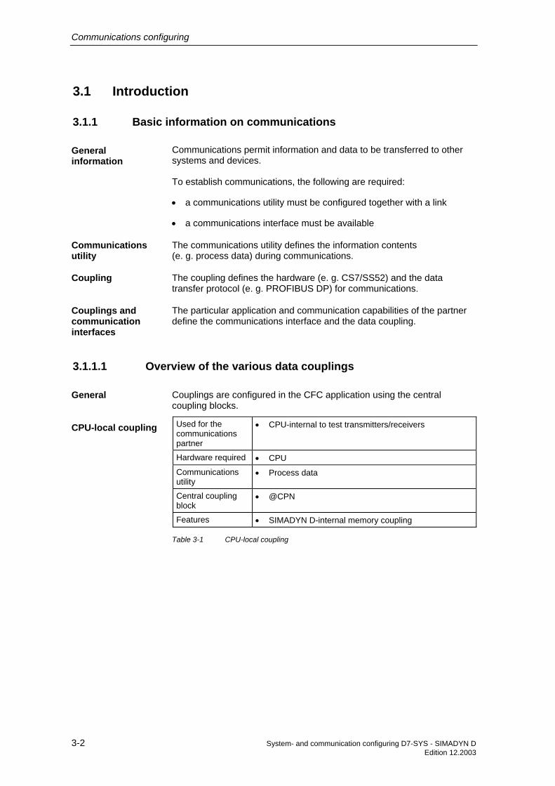
Communications configuring
3-2 System- and communication configuring D7-SYS - SIMADYN D Edition 12.2003
3.1 Introduction
3.1.1 Basic information on communications
Communications permit information and data to be transferred to other systems and devices.
To establish communications, the following are required:
• a communications utility must be configured together with a link
• a communications interface must be available
The communications utility defines the information contents (e. g. process data) during communications.
The coupling defines the hardware (e. g. CS7/SS52) and the data transfer protocol (e. g. PROFIBUS DP) for communications.
The particular application and communication capabilities of the partner define the communications interface and the data coupling.
3.1.1.1 Overview of the various data couplings
Couplings are configured in the CFC application using the central coupling blocks.
Used for the communications partner
• CPU-internal to test transmitters/receivers
Hardware required • CPU
Communications utility
• Process data
Central coupling block
• @CPN
Features • SIMADYN D-internal memory coupling
Table 3-1 CPU-local coupling
General information
Communications utility
Coupling
Couplings and communication interfaces
General
CPU-local coupling

Communications configuring
System- and communication configuring D7-SYS - SIMADYN D 3-3 Edition 12.2003
Used for the communications partner
• CPU-CPU communications for higher data quantities as an alternative to $ signals
Hardware required • Communications buffer module (e. g. MM11)
Communications utility
• Process data
Central coupling block
• @CMM
Features • SIMADYN D-internal memory coupling
Table 3-2 Communications buffer coupling
Used for the communications partner
• SIMADYN D
Hardware required Communication modules for the master interface: • CS12 (master for 1 slaves) • CS13 (master for 4 slaves)
• CS14 (master for 8 slaves)
Hardware required Communications module for the slave interface:
• CS22
Communication utility
• Process data, message system, trace
Central coupling block
• @CS1 • @CS2
Features • Fiber-optic cable • CS12:
Point-to-point coupling with CS22 slave interface
• CS13: Coupling with 4slave interfaces CS22 • CS14: Coupling with 8 slave interfaces CS22 • CS22: Coupling with master interfaces CS12, CS13 or
CS14
• Parallel coupling of up to 9 SIMADYN D subracks • All subracks can be synchronized • Uniform system clock possible (unified)
• Fast
• The maximum distance between 2 subracks is 500 m • The master and slave can be disabled (disconnected)
at any time
• Can only be used with subracks which have a C bus
Table 3-3 Subrack coupling
Communications buffer coupling
Subrack coupling

Communications configuring
3-4 System- and communication configuring D7-SYS - SIMADYN D Edition 12.2003
Used for the communications partner
• SIMADYN D • SIMATIC S5/S7 • Third-party systems • COROS
Hardware required • CSH11 communications module
Communication utility
• Layer 2: Process data • Layer 4: Process data, message system • Layer 7: (STF): Process data and message system
Central coupling block
• @CSH11
Features • Standardized bus according to Ethernet (IEEE 802.3) • A maximum of 1024 nodes can be coupled
• Baud rate: 10 Mbaud • The SINEC system time can be input • The bus can be parameterized using the NML
software
Table 3-4 Industrial Ethernet coupling (SINEC H1)
Used for the communications partner
• SIMATIC S5/S7 • SIMOVERT/SIMOREG drive converters
• ET200 • SIMADYN D • Certified third-party equipment/devices
Hardware required • CS7 communications module with SS52 communications module
Communications utility
• Process data • Parameter processing
Central coupling block
• @CSPRO
Features • Standardized multi-master bus for communications between SIMADYN D and a maximum of 123 communication partners
• Master slave principle (CS7/SS52 is master and/or slave)
• PROFIBUS standard according to EN 50170 • Fast
• Max. 12 Mbaud • Maximum net data length, 244 bytes • Bus is parameterized using the COM PROFIBUS
software
Table 3-5 PROFIBUS DP coupling
Industrial Ethernet (SINEC H1)
PROFIBUS DP

Communications configuring
System- and communication configuring D7-SYS - SIMADYN D 3-5 Edition 12.2003
Used for the communications partner
• SIMADYN D (only if PROFIBUS FDL is used as a result of other communication partners)
• SIMATIC S5/S7
• Certified third-party equipment/devices
Hardware required • Master: CS7 communications module with SS5 communications module
Communications utility
• Process data
Central coupling block
• @CSL2L
Features • Standardized multi-master bus to couple SIMADYN D (master) to a maximum of 126 coupling partners
• Token principle with secondary master-slave principle • PROFIBUS Standard according to EN 50170 • Max. 1.5 Mbaud • Maximum net data length 232 bytes
Table 3-6 PROFIBUS FDL coupling
Used for the communications partner
• SIMADYN D (only if PROFIBUS FMS is used as a result of other communication partners)
• SIMATIC S5/S7
• Certified third-party equipment/devices
Hardware required • Master: CS7 communications module with SS5 communications module
Communications utility
• Process data • Message system
Central coupling block
• @CSL2F
Features • Standardized multi-master bus to couple SIMADYN D (master) to a maximum of 126 coupling partners
• Token principle with secondary master-slave principle
• PROFIBUS standard according to EN 50170 • Master-master- and master-slave communications
possible
• Max. 1.5 Mbaud • Maximum net data length 232 bytes • The bus can be parameterized using COM SS5
software
Table 3-7 PROFIBUS FMS coupling
PROFIBUS FDL
PROFIBUS FMS

Communications configuring
3-6 System- and communication configuring D7-SYS - SIMADYN D Edition 12.2003
Used for the communications partner
• CFC • Basic service tool • SIMADYN D
Hardware required • CS7 communications module with SS4 communications module
Communications utility
• Service, process data
Central coupling block
• @CSD01
Features • Low-cost, point-to-point connection
• 2400, 4800, 9600 or 19200 baud • Either a 20 mA- or V.24 interface can be used • Maximum net data length, 248 bytes
Table 3-8 DUST 1 coupling
Used for the communications partner
• Printer
Hardware required • CS7 communications module with SS4 communications module
Communications utility
• Message system
Central coupling block
• @CSD02
Features • Low-cost, point-to-point connection
• 2400, 4800, 9600 or 19200 baud • Either a 20 mA- or V.24 interface can be used
Table 3-9 DUST2 coupling
DUST1
DUST2

Communications configuring
System- and communication configuring D7-SYS - SIMADYN D 3-7 Edition 12.2003
Used for the communications partner
• SIMATIC S5 • Other systems, which are suitable for the
3964R/RK512 protocol (e. g. Allen-Bradley)
Hardware required • CS7 communications module with SS4 communications module
Communications utility
• Process data
Central coupling block
• @CSD03
Features • Point-to-point connection • 3964 (R) data transfer protocol with/without RK512
communications protocol
• 2400, 4800, 9600 or 19200 baud • Either 20mA- or V.24 interface possible • Maximum net data length, 750 bytes
Table 3-10 DUST3 coupling
DUST3

Communications configuring
3-8 System- and communication configuring D7-SYS - SIMADYN D Edition 12.2003
Used for the communications partner
• SIMOVERT, SIMOREG drive converters • OP2 operator control devices • VD1 numerical display
Hardware required • Master: CS7 communications module with SS4 communications module
Communications utility
• Process data • Parameter processing
• Message system • Display
Central coupling block
• @CSU
Features • Single-master bus for communications between SIMADYN D (master) with a maximum of 31 communication partners
• Master-slave principle (CS7/SS4 is the master) • 9,6, 19,2, 38,4, 93,75 or 187,5 kbaud • For drive converters: Maximum net data length is
28 bytes
Table 3-11 USS master coupling
Used for the communications partner
• CFC • WinCC
• SIMATIC-OPs
Hardware required • CS7 communications module with SS52 communications module
Communications utility
• Service • S7 communications
Central coupling block
• @CSMPI
Features • Multi-master bus with a maximum of 126 nodes • 187,5 kbaud • Standard for SIMATIC S7
Table 3-12 MPI coupling
3.1.2 Overview of the communication utilities
Various data can be transferred via the communication interfaces, for example, process data and messages.
The communication utilities define which information/data is to be transferred. The communication utilities are defined by configuring the communication modules.
USS master
MPI
General

Communications configuring
System- and communication configuring D7-SYS - SIMADYN D 3-9 Edition 12.2003
Communications utility
Description Communication blocks to be configured
Display control Values can be transferred and changed. (OP2, VD1)
Function blocks for displays: @DIS, DIS...
Message system Establishing alarm- and fault systems
Special message blocks: @MSC, MER..., MSI...
Parameter processing
Reading and processing parameter values from drive converters
@DPH, DPI
Process data Transferring process data (setpoints and actual values)
Send- and receive blocks: CTV, CRV, CCC4, CDC4
Service Diagnostics and analysis of CPU programs / CFC
Service- function block: SER
Time synchronization Time synchronization of all of the CPUs used (e. g. in order to compare messages with a time stamp).
Special function blocks: RTC...
Data trace Trace process quantities @TCP, TR...
Network Transparent data transfer beyond the subrack
@NMC, ...
S7 communications Operator handling and visualization of CPU program / CFC
Communication function block: S7OS
Table 3-13 Overview of the communication utilities
3.1.3 Communication block I/Os
3.1.3.1 Initialization input CTS
Communication blocks which access a data interface have a CTS input.
The following are specified at the CTS input:
1. The configured name for the communications module Syntax for module names: − the name is 1 - 6 characters long
− 1st character: A - Z
− 2nd - 6th characters: A - Z, 0 - 9, _
2. Connector of the data interface if the data interface is on a CS7 communications module Syntax for the connector designation:
Communication utilities
Data at the initialization input

Communications configuring
3-10 System- and communication configuring D7-SYS - SIMADYN D Edition 12.2003
− enter "." after the module name
− the name after "." is 3 characters long
− "X01", "X02" or "X03"
Configuring example of a subrack:
Slot Module Configured module name in HWConfig
Possible data entry at the CTS input
S01 PM5 "D01_P1" "D01_P1"
S03 MM11 "KOPPEL" "KOPPEL"
S04 CS7 An SS4 is inserted at "KOMM1" at X01, and an SS5 at X02)
"KOMM1.X01" "KOMM1.X02"
S06 CSH11 "H1" "H1"
Table 3-14 Configuring example of a subrack
3.1.3.2 Address connections AT, AR and US
Communication blocks, which can access a data interface, have an address connection.
Depending on the particular block type, a differentiation is made between three address connection types:
• AT connection: Available when transmitting
• AR connection: Available when receiving
• US connection: Available for function blocks, which are processing a send- and a receive channel
The data entries at the address connection are independent of types AT, AR or US. The possible data are:
• "Channel name"
• "Channel name. Address stage 1"
• "Channel name. Address stage 1. Address stage 2"
• The channel name addresses a channel at a data interface.
• Transmitter and receiver, which access a data interface with the same channel name, communicate with one another.
• The channel name consists of a maximum of 8 ASCII characters, excluding "Point" and "@".
NOTE It is not checked as to whether a channel name is configured a multiple number of times. The configuring engineer must uniquely assign the channel names at a data interface for each transmitter/receiver at the AT,
Example of data entry at CTS
General
Address connection types
Possible address connection data
Channel name

Communications configuring
System- and communication configuring D7-SYS - SIMADYN D 3-11 Edition 12.2003
AR or US connections. If this condition is not fulfilled, then
• transmitter/receiver may be used a multiple number of times, but uncoordinated.
• the transmitter/receiver could log-off with a communications error.
Exceptions:
• Several transmitters are permitted for the "Select" data transfer mode.
• Several receivers are permitted for the "Multiple" data transfer mode.
• There is address stage 1 and address stage 2.
• Several couplings, for example, PROFIBUS, require the address stage to be specified for data transfer. For subrack couplings, for example, address stages are not specified.
• Address stage 1 is a maximum of 14 characters long, address stage 2, maximum 20 characters.
• Significance and contents of the address stages are described for the particular coupling.
3.1.3.3 Data transfer mode, MOD input
There are five various data transfer modi for the various communication requirements:
• handshake
• refresh
• select
• multiple
• image
The data transfer mode is specified at the MOD connection of the appropriate transmitter or receiver.
The "Handshake" data transfer mode is used,
• if information loss may not occur due to data being overwritten, and
• if there is precisely one receiver for each transmitter.
"Handshake" defines a sequential channel processing. The transmitter first deposits a new data set in the channel after the receiver has acknowledged that it has received the first data set. A net data buffer is provided for data transfer.
The transmitter inputs the net data into the channel in an operating cycle and the receiver reads them out in an operating cycle.
Address stages
Overview
Selecting the data transfer mode
"Handshake" data transfer mode

Communications configuring
3-12 System- and communication configuring D7-SYS - SIMADYN D Edition 12.2003
Transmitter Receiver
KVL = channel administratorNDP =net data buffer
KVL
NDP
Fig. 3-1 Data transfer in the "Handshake" mode
The "Refresh" data transfer mode is used,
• if the latest data is always to be made available to a receiver and
• if there is precisely one receiver for each transmitter.
"Refresh" overwrites when it transfers data. The transmitter always deposits the latest data set in the channel without the receiver having acknowledged that it has received the last data set. There are two net data buffers for data transfer, which are used as alternating buffer system. The transmitter flags in which buffer the latest data are located.
Transmitter KVL
NDP1
Receiver
NDP2
KVL = channel administratorNDP =net data buffer
Fig. 3-2 Data transfer in the "Refresh" mode
"Refresh" data transfer mode

Communications configuring
System- and communication configuring D7-SYS - SIMADYN D 3-13 Edition 12.2003
The "Select" data transfer mode is used,
• if information loss may not occur due to data being overwritten, and
• if there can be as many transmitters as required for one receiver
"Select" defines a sequential channel processing. If the receiver acknowledges that it has received the last data set, then the transmitter deposits a new data set in the channel. A net data buffer is provided for data transfer. A channel administrator controls the data transfer.
All of the configured transmitters use the same net data buffer. There is no defined sending sequence for the transmitter. The first one sends first. In order to achieve controlled data transfer, a "1" may only be specified at one transmitter at the EN connection.
The transmitter must be configured in a shorter sampling time than the receiver.
Trans. 1 KVL
NDPTrans. 2
....
Trans. n
Receiver
KVL = channelNDP =net data buffer
Fig. 3-3 Data transfer in the "Select" mode
The "Multiple" data transfer mode is used,
• if receivers are to always be provided with the latest data, and
• if as many receivers as required are available for each transmitter.
"Multiple" overwrites data when transferring data. The transmitter always deposits the latest data set in the channel without the receiver first acknowledging that it has received the last data set.
If a transmitter overwrites a buffer, from which a receiver is presently reading, then the receiver rejects the data which were last received. Receive is repeated in the next operating cycle.
There are two net data buffers for data transfer, which are used as alternating buffer system. The transmitter flags in which buffer the latest data are located.
The receivers must be configured in the same or shorter sampling time than the transmitter (the receivers must therefore operate faster).
"Select" data transfer mode
"Multiple" data transfer mode

Communications configuring
3-14 System- and communication configuring D7-SYS - SIMADYN D Edition 12.2003
Transmitter KVL
NDP1
NDP1....
Receiver 1
Receiver 2
Receiver n
KVL = channelNDP =net data buffer
Fig. 3-4 Data transfer in the "Multiple" mode
The "Image" data transfer mode” is used for the FM 458-1 DP to communicate via the PROFIBUS DP interface,
• if all of the receivers, which are configured in a task, should be provided with data that come from the same DP cycle,
• if all transmitters, which are configured in the same task, wish to send their data to the DP slaves in the same DP cycle.
To do this, transmitter and receiver FBs synchronize themselves within a task in order to supply consistent data. They form a so-called “consistency group”. All receiver FBs, associated with such a consistency group, fetch their net (useful) data from a common alternating buffer and all of the transmitter FBs deposit their data in such a buffer.
"Image" is an overwriting data exchange (refer to refresh). There are two net (useful) data buffers which are used for data exchange. They are used as alternating buffer system.
This data transfer mode is only permitted for the PROFIBUS DP interface of the FM458-1 DP application module.
"Image" data transfer mode

Communications configuring
System- and communication configuring D7-SYS - SIMADYN D 3-15 Edition 12.2003
Transmitter 1
KVL
NDP 1NDP 2
Receiver 1
Receiver 2
Receiver 3
KVL = Channel manager NDP =Net data buffer
Transmitter 2
Transmitter 3
Fig. 3-5 Data transfer in the "Image" mode
3.1.3.4 Firmware status, ECL, ECO connection
Central coupling blocks, which communicate with a firmware (e. g. @CSD01 or @CSH11) have outputs ECL and ECO.
The outputs ECL and ECO indicate the status of the appropriate firmware:
• ECL=0 and ECO=0: The firmware is in an error-free condition.
• ECL=0 and ECO>0: The firmware has an error condition, which can be rectified by the configuring engineer or user. The error cause is described in the Chapters associated with the individual couplings.
• ECL>0 and ECO>0: An irreparable firmware error is present.
3.1.3.5 Status display, output YTS
The block outputs an error code or the instantaneous data transfer status at its output YTS.
• Real (severe) run-time errors
• Configuring errors, which are identified when the system is initialized, and which are displayed at the 7-segment display of the CPU using a flashing "C".
• Temporary status displays and alarms
General
Function
General
Displayed error

Communications configuring
3-16 System- and communication configuring D7-SYS - SIMADYN D Edition 12.2003
The value at output YTS can be read as decimal number using CFC.
Additional information regarding the significance of the decimal number, refer to the online help "Help on events".
3.1.4 Mode of operation of the couplings
A coupling functions as follows:
• CPUs transfer data with a coupling module via the backplane bus (C- or L bus).
• For serial couplings (e. g. for SINEC H1) the firmware on the coupling module "re-structures" and "packages" the data, so that they correspond to the required telegram structure and protocol.
• If the communications partner is also a SIMADYN D (subrack coupling, buffer memory coupling), then the data are not conditioned.
Data transfer viabackplane bus
CPU Coupling module
Data interface
Serial connection(connector at thefront panel)
Re-structuring and packagingof the data is realized by the firmwareon the coupling module
Fig. 3-6 Data transfer between the CPU and coupling module
• The C- and L buses are structured the same, have the same mode of operation and the same performance features.
• The coupling module bus connection defines whether data are trans-ferred between the CPU and the coupling module via the C- or L bus.
As the data interfaces are located on external coupling modules and not locally on a CPU, they can be used by all CPUs in a subrack. However to use a data interface, the CPU and the coupling module must have the same bus connection.
NOTE For the local CPU coupling, the data interface is located on the CPU RAM. This data interface cannot be accessed by any of the other subrack CPUs. It can only be used by that CPU on which it was configured.
Fault diagnostics
General
C- and L bus
Access to the data interface

Communications configuring
System- and communication configuring D7-SYS - SIMADYN D 3-17 Edition 12.2003
A coupling module is always initialized (basic initialization) at system run-up.
The CPU to the left of the coupling module and with the same bus connection as the coupling module executes the following tasks:
• checks as to whether the coupling module can be "addressed"
• formats the data interface
The required coupling module is configured in HWConfig. When initializing a coupling (basic initialization), no explicit configuring steps must be executed.
3.1.4.1 Central coupling blocks
The central coupling blocks have the following functions for a coupling:
• Initialization:
− copying the configured initialization information (this is configured at the initialization inputs) at the data interface
− defines as to whether the data interface is in an error-free condition.
• Enabling:
− after initializing by the central coupling blocks and the coupling module firmware, the central coupling block enables the coupling for all transmitters and receivers in the same subrack. Data transfer can now start.
− for timing reasons, a coupling is always enabled in the RUN condition after several sampling times.
• Monitoring:
− the central coupling blocks provide information at their outputs about the status of the coupling and, if relevant, the status of the firmware.
When configuring, the following points must be observed:
• Exactly one central coupling block must be configured for each coupling.
• The central coupling blocks can all be configured on a CPU of a subrack or they can be distributed over various CPUs of a subrack.
− configuring all central coupling blocks on a CPU simplifies, for example, diagnostics.
• Central coupling blocks have no transmit- or receive functionality.
• All central coupling blocks must be configured in a sampling time 32 ms ≤ TA ≤ 256 ms
Basic initialization
Configuring the coupling module
Function of the central coupling blocks
Configuring the central coupling blocks

Communications configuring
3-18 System- and communication configuring D7-SYS - SIMADYN D Edition 12.2003
The central coupling block makes an entry into the communications error field and no longer processes the coupling module, if
• a central coupling block identifies an error when being initialized
• a firmware does not respond or manifests erroneous behavior,
• the central coupling block is running on the incorrect communications module.
3.1.4.2 Transmitters and receivers
Transmitters and receivers are:
• function blocks, which access the data interface of a coupling, either writing and/or reading.
• part of the communications utility which uses the coupling.
Examples of transmitters:
• message output, function block MSI: Copies messages from the message buffer into a data interface
• process data transmit block CTV
Examples of the receivers:
• process data receive block CRV
As transmitters and receivers don’t differentiate between the individual couplings, at the block inputs of the transmitter and receiver, a coupling type must not be specified.
• CTS input to specify the coupling module
• address connection AR, AT or US to specify channel names and coupling-specific addresses
Before transmitters and receivers can transfer data, they must first identify- and synchronize with one another:
• Identification is realized via the data configured at the connections CTS and AT, AR or US.
• Synchronization is only possible,
− if a transmitter identifies its partner as receiver (or vice versa).
− if the length of the reserved data areas coincide.
− if the net data structure is compatible.
− if the data transfer mode is identical (data entry at the MOD input for transmitters/receivers).
Errors
General
Data entries at the connections
I/O, trans./ receivers
Synchronizing transmitters and receivers

Communications configuring
System- and communication configuring D7-SYS - SIMADYN D 3-19 Edition 12.2003
If one of these conditions is not fulfilled, then the synchronizing transmitter/receiver logs-off with a communications error.
3.1.4.3 Compatible net data structures
The net data structures include information regarding the structure of the net data to be transferred:
• data regarding the position and data types of the associated net data
The net data of the transmitter and receiver must be structured the same to permit data transfer between the transmitter and receiver.
The following standardized data types are used:
Standardized data type SIMADYN D data type Length in bytes
Integer 16 Integer 2
Integer 32 Double Integer 4
Unsigned 8 Bool, Byte 1
Unsigned 16 Word 2
Unsigned 32 Double Word 4
Floating Point Real, SDTIME 4
Octet-String - 1
Time and Date - 6
Table 3-15 Standardized data types
NOTE The SIMADYN D connection types (e. g. SDTIME) are not used as data types, as the coupling partner does not always have to be a SIMADYN D function block.
• Octet string An octet string is an unstructured data type which does not appear at the block I/O (refer to the Chapter Channel marshalling blocks CCC4 and CDC4).
• Time and date Data type for the time which does not appear at the block I/O (refer to communications utility, message system). Value range
− 1st octet and 2nd octet: Specify the date relative to 1.1.1984. Resolution=1 day 0 days≤d≤65535 days
General
Data types

Communications configuring
3-20 System- and communication configuring D7-SYS - SIMADYN D Edition 12.2003
− 3rd octet to 6th octet: Specify the time between 00:00 and 24:00. Resolution = 1ms 0 ms≤x≤86400000 ms The first 4 bits are not assigned in the sixth octet
0000 xxxx xxxx xxxx xxxx xxxx xxxx xxxx dddd dddd dddd dddd6.octet 1.octet
Significance 227
2.octet3.octet
Significance 200
Significance 215
Significance 200
Fig. 3-7 Time and date
3.1.4.4 Number of coupling modules in a subrack
The number of CS coupling modules (CSH11, CS12/13/14, CS22 and CS7) are restricted by two system limits:
• subrack size The largest subrack in the SIMADYN D system has 24 slots. As a subrack must have at least one CPU, theoretically, 23 slots remain.
• available address space In practice, these limits are seldomly reached. For CS modules, the L- and C bus each have 1 Mbyte address space.
The individual CS modules always occupy a constant address space on the backplane bus.
• Example CS7 always occupies 64 Kbyte on the L bus, independent of how many modules are configured.
Module type Backplane bus Occupied address space
CS12/13/14, CS22 C bus 128 Kbyte CSH11 C bus 64 Kbyte
CS7 L bus 64 Kbyte
Table 3-16 Occupied address space
3.1.4.5 Reorganizing a data interface
A data interface can be re-formatted without having to interrupt the RUN condition or diminish performance.
Overview
Assigned address space
General

Communications configuring
System- and communication configuring D7-SYS - SIMADYN D 3-21 Edition 12.2003
Several central coupling blocks have a CDV connection (Bool. data type). If there is a positive edge at the CDV input, the central coupling block inhibits the coupling, and after approx. 10 seconds, formats the data interface. The data interface is then enabled again.
During this inhibit time and while the data interface is being re-formatted, all transmitters/receivers go into a wait condition. After enabling, channels log-on (register) and synchronize just the same as when the system runs-up.
The subrack coupling is an application. Here, data areas can be reserved which are not used.
• If individual subracks with a CS22 module are shutdown, and the number of transmitters or receivers is reduced due to a configuring change, the "earlier" reserved data areas on the CS12/13/14 are kept.
• For communications between CS22-CS22, the CS12/13/14 subracks are only used as data interface, not as coupling- or communications partner. The unused data areas are eliminated by re-organizing the CS12/13/14.
Formatting the data interface
Example

Communications configuring
3-22 System- and communication configuring D7-SYS - SIMADYN D Edition 12.2003
3.2 Couplings on the subrack
These couplings include:
• local CPU coupling
• communications buffer coupling
• coupling to EP3 modules
3.2.1 Local CPU coupling
The local CPU coupling does not require a coupling module. This coupling type can only be used by function blocks, which are located on the same CPU as the data interface. The data interface always lies on that CPU and is 16 kbyte.
The coupling is mainly used for autonomous tasks (e. g. a closed-loop control) to provide defined interfaces. Thus, when configuring a project, it is simple if a CPU is "overloaded" to shift the complete task to another CPU without involving extensive configuring work. Communications can, for example, then be realized via the data interface in the buffer. Only the data at the CTS connection has to be changed at all communication function blocks.
The @CPN central blocks cyclically initialize and monitor the coupling. Thus, at the start of cyclic operation, the coupling is not enabled for all senders/receivers, but only after a delay of several operating cycles. The @CPN central block monitors the coupling after the coupling has been enabled.
A @CPN central coupling block must be configured to initialize and monitor the coupling.
For the local CPU coupling, only the channel name has to be specified at the AT, AR or US connections of the send/receive blocks. Data for address stages 1 and 2 should not be configured. Transmitters and receivers with the same channel names communicate with one another.
3.2.2 Communications buffer coupling
The 16 kbyte data interface for the communications buffer coupling is located on a communications buffer.
The hardware consists of modules MM11, MM3 or MM4.
Overview
General
Application
Initialization and monitoring
Configuring
General

Communications configuring
System- and communication configuring D7-SYS - SIMADYN D 3-23 Edition 12.2003
CPUMM11MM4MM3
Data transfer via the backplane bus CPU
Fig. 3-8 Communications buffer coupling
The communications buffer coupling is used to transfer data between various CPUs of a subrack. Contrary to $ signals, higher quantities of data are transferred more effectively.
A @CMM central block must be configured on any CPU of the subrack to initialize and monitor the coupling.
The @CMM central block cyclically initializes and monitors the coupling. Therefore, the coupling is not enabled for all transmit/receive blocks at the start of cyclic operation but only after a delay of several operating cycles. The @CMM central block monitors the coupling after the coupling has been enabled.
The communications buffer coupling can only be used by send/receive blocks which are configured on the same subrack.
For the communications buffer coupling, only the channel name has to be specified at the AT-, AR- or US connections of the transmit/receive blocks. Address stages 1 and 2 do not have to be configured. Transmitters and receivers with the same channel names communicate with one another.
3.2.3 Coupling to EP3 modules
The coupling to EP3 modules is handled just like any other coupling. The data interface is located on the EP3 module (this module is not configured/parameterized with D7-SYS). The data interface is 16 kbyte.
DPRCPU
EP3Data transfer via the backp lane bus
Fig. 3-9 Coupling to EP3 modules
A central block @CEP must be configured on any of the CPUs of a subrack to initialize and monitor the coupling.
Application
Initialization and monitoring
Configuring
General
Monitoring and initialization

Communications configuring
3-24 System- and communication configuring D7-SYS - SIMADYN D Edition 12.2003
The @CEP central blocks cyclically initialize and monitor the coupling. The coupling is therefore not enabled at the start of cyclic operation for all transmitters/receivers, but only after a delay of several operating cycles. After the coupling has been enabled, the @CEP central block monitors the coupling.
NOTE Only communication utility process data can be configured.
• For the coupling to EP3 modules, only the channel name has to be specified at the AT- and AR I/O of the transmit/receive blocks. Address stages 1 and 2 do not have to be configured.
• For channel names, the EP3 modules only evaluate the 5th and 6th character of the channel name. All other characters can be selected as required.
Configuring

Communications configuring
System- and communication configuring D7-SYS - SIMADYN D 3-25 Edition 12.2003
3.3 Subrack coupling
A maximum of 9 SIMADYN D subracks with C-bus connection can be coupled with a fiber-optic cable subrack coupling.
The hardware uses CS12, CS13, CS14 and CS22 modules
The subrack which accommodates the CS12, CS13 or CS14 modules will be designated as the master subrack in the following.
The subrack in which the CS22 module is inserted, will be designated as the slave subrack.
One central block @CS1 or @CS2 must be configured on any CPU in each subrack for coupling initialization and coupling monitoring.
CS1
4
CS2
2
CS2
2
CS2
2
Subrack No. 1
CS2
2
16
CS2
2
CS2
2
CS2
2
CS2
28
No. 2 No. 3 No. 4 No.5
No.6 No.7 No.8 No.9
CPU
CPU
CPU
CPU
CPU
CPU
CPU
CPU
CPU
Fig. 3-10 Maximum configuration with CS14
General
Initialization and monitoring

Communications configuring
3-26 System- and communication configuring D7-SYS - SIMADYN D Edition 12.2003
Subrack No..1
No. 2C
PU
CS1
2
CPU
CS2
2
Fig. 3-11 Point-to-point coupling with CS12
No.. 2
Subrack No.1
No. 3 No. 4 No. 5
8
CPU
CS1
3
CS2
2
CPU
CPU
CPU
CS2
2
CS2
2
CS2
2
CPU
Fig. 3-12 Configuration for four slaves with CS13

Communications configuring
System- and communication configuring D7-SYS - SIMADYN D 3-27 Edition 12.2003
3.3.1 Hardware structure
• Only subracks with C-bus connection can be coupled with one another (e. g. SR24).
• The master subrack, has, depending on the number of slaves to be connected, a CS12-, CS13 or a CS14 module. The slave subracks have a CS22 module.
• A subrack can accommodate several CS12/CS13/CS14/CS22 modules. Thus, several different subrack couplings can be configured in a subrack. The CS12/CS13/CS14/CS22 modules of a subrack coupling must all be configured in different subracks.
3.3.2 Scope of supply
All of the slave subracks are permanently coupled to the master subrack, as a slave subrack must continuously access the memory in the master subrack.
• The master/slave subracks can be powered-up in any sequence.
• All subracks can be powered-down and up again in continuous operation.
• If a slave subrack is powered-down and up again, then communications between the other nodes (master and a maximum of seven slaves) is not influenced.
• Slave subracks which are powered-down can be re-configured and powered-up again. The number of transmitters and receivers can also be changed (e. g. if one transmitter too little was configured).
• As soon as the slave partner, which was powered-down, is powered-up again, a new connection is established between the new partner which has been powered-up again and all other partners. This is also valid for slave-slave communications, i. e. if the CS12-, CS13- or CS14 module is only used as data transfer area and not as communications partner. Slave-slave communications are interrupted when the master subrack is powered-down.
NOTE It is not permissible to remove the fiber-optic cable during operation as this can result in a CPU crash.
3.3.3 Response when "shutting down" a coupling partner
The master subrack is shutdown:
The @CS2 central block can no longer access the master subrack and prepares a restart (in addition, the CDM block output is set to "faulted", refer to @CS2 mask). The system then waits until the master subrack is powered-up.
Overview
Overview
Response of the master subrack

Communications configuring
3-28 System- and communication configuring D7-SYS - SIMADYN D Edition 12.2003
All slave transmit/receive blocks can no longer access the master subrack and start a new channel log-on.
The slave subrack is shutdown:
The @CS1 central block and the maximum seven additional @CS2 central blocks decrement their particular NCP connection (i. e. the number of active slave subracks is reduced by one). Otherwise, there is no response, and the NCP connections are incremented again after the appropriate slave subrack runs-up again. All of the configured transmit/receive blocks, whose coupling partner is located on the subrack which is shutdown, wait until the subrack has run-up again.
3.3.4 Response when "powering-up" the master subrack
If the master subrack is powered-up again while the slave subracks are operational, it can be assumed, that for a short period of time, increased computation time will be required to establish the connection for CPUs to communicate via the subrack coupling. For already highly utilized CPUs, this can result in an 'E' being displayed at the 7-segment display (error in the task administrator).
3.3.4.1 Acknowledging
The 'E' can be acknowledged in two ways:
When manually acknowledging, after the connection has been established, the 'E' can be acknowledged by depressing the red acknowledge button on the CPU.
For automatic acknowledgement, the following must be configured on all CPUs in the slave subrack which communicate via the subrack coupling. Automatic acknowledgement can be implemented in two different ways using this particular configuration:
1. All YEV outputs, of the function blocks communicating via the subrack coupling are monitored using a software which has to be configured. If the value of all YEV outputs is less than 9 (i. e. initialization has been completed), then the input NOT.I is set to '1'. Using the CDM output of the @CS2 central block, it is ensured that the system is only automatically acknowledged if the master subrack has actually been powered-up. Using the time limit (input T at PCL), automatic acknowledgement has to be realized within a certain time. The 'E' on the 7-segment display is now automatically acknowledged using the SYF4 function block.
2. If not all of the YEV outputs can be monitored or should be monitored, input OR.I2 should be set to "1" and input NOT.I should not be connected at all. In this case, the CPU is only acknowledged within the time, set at connection T of the PCL after the master subrack has been powered-up (output of @CS2.CDM).
Response of the slave subrack
Response
Manual acknowledge
Automatic acknowledgement

Communications configuring
System- and communication configuring D7-SYS - SIMADYN D 3-29 Edition 12.2003
Righthandmargin
Lefthandmargin
Channel init. ready; e. g.all YEV outputs < 9;NOT.I = 1
Q
NOT
-I- Q
OR
-I1I2
--
Q
AND
-I1I2I3I4
--
--
1
Q
PCL
-IT
--
Y1Y2Y3Y4QF
SYF4
----
NOIAC
--
4
If not all channelsare to be checked;OR.I2 = 1
Enable acknowledge-ment;AND.I3 = 1
Acknowledgment onlystarts if the mastersubrack is [email protected] connection
Maximum time withinwhich 'E' isacknowledged
Fig. 3-13 Automatic acknowledgement of 'E'
3.3.5 Restart frequency
An additional important communications feature for external communication interfaces is the restart frequency of transmitters/receivers. Transmitters/receivers always re-locate their old channel and re-synchronize with them.
Subracks can be powered-up and down again in any sequence. The transmitters/receivers of the subracks, in which the CS22 is inserted, synchronize themselves to the previous channelsat each restart (new run-up).
If a transmitter/receiver identifies the "right" channel at log-on, then it cannot identify
Synchronizing transmitters and receivers
Communications configuring
3-30 System- and communication configuring D7-SYS - SIMADYN D Edition 12.2003
• if it had previously used this channel before.
• whether this channel is presently being used by another transmitter/receiver (or transmitter or receiver).
3.3.6 Configuring
• For a fiber-optic cable subrack coupling, all of the CS22 modules must have different names. If names have been assigned twice, then the appropriate central blocks log-off with multiple configuring (FB disable).
• All CS22 modules and the CS12-, CS13- or CS14 modules of a subrack must be inserted in different subracks.
• The sampling time range, 32 ms≤TA≤256 ms, valid for central coupling blocks, is also valid for the subrack coupling central blocks @CS1 and @CS2. It should also be observed that the @CS2 central blocks may only be configured, as maximum, in twice the sampling time as the @CS1 central block. The actual sampling time (in milliseconds) is decisive and not the cyclic task (T1, T2 etc.)
− Example: If the @CS1 central block was configured in 100ms, the @CS2 central blocks can be configured in a sampling time up to 200ms (180ms, 150ms, 130ms, 50ms etc. are thus permitted).
The data interface is located on the dual port RAM of the CS12-, CS13- or CS14 module. The available data transfer area is 128 kbytes.
The coupling initialization and monitoring is handled by the @CS1 and @CS2 central blocks in the RUN status. Thus, the coupling is not enabled at the start of cyclic operation for all transmit/receive blocks, but is delayed by several sampling cycles. The coupling is always first enabled in the master subrack and then in the slave subracks.
After the coupling has been enabled, central blocks @CS1 and @CS2 monitor the coupling. In this case, the number of active coupling partners is output at the central block outputs.
For the subrack coupling, only the channel name has to be specified at the AT- and AR inputs of the transmit/receive blocks. Names should not be configured for address stages 1 and 2. Transmitters and receivers with the same channel names communicate with one another.
Rules
Data interface
Initialization and monitoring
Names at the AT- and AR inputs

Communications configuring
System- and communication configuring D7-SYS - SIMADYN D 3-31 Edition 12.2003
3.4 Industrial Ethernet coupling (SINEC H1)
There are three versions for communications via SINEC H1:
• Layer 2 The data are directly transferred via the Ethernet defined in the SINEC H1 protocol stack. The transfer is without physical connection and without any handshaking (acknowledgement). The communication partners are known as transmitters and receivers. data is packed in telegrams and transmitted or received. All SIMADYN D communication utilities can communicate via SINEC H1 in this way.
• Layer 4 The data are transferred via the ISO Transport Layer, defined in the SINEC H1 protocol stack. The data transfer requires a physical connection and handshaking (acknowledgement). The communication partners are designated as transmitter and receiver. Data is packed into telegrams and transmitted or received. All SIMADYN D communication utilities can communicate via SINEC H1 in this way.
• Layer 7 (STF), STF=SINEC technological functions The data to be transferred are defined as variable (object) and are processed with STF utilities "Read variable", "Write variable". For STF utilities, there is always a client and a server. The server defines the variable and responds to utility requests; the client issues the utility requests. SIMADYN D communication utilities "Process data" and "Message system" can communicate via SINEC H1 in these ways.
NOTE When using layer 4 or layer 7:
To configure the bus of the CSH11 coupling module (with integrated CP1470) the NML configuring tool is required, Order No. 6GK 1740-0AB00-0BA0!
Each bus node requires the following to allow it to operate on the bus:
• Ethernet address
− is assigned when configuring in the CFC.
• Application associations (layer 7) and data transfer connections (layer 4 and layer 7)
− defined routes to transfer data between the bus nodes, which are configured using NML.
• Variables (layer 7) and telegrams (layer 2 and layer 4)
− for SIMADYN D - are assigned when configuring in CFC.
Overview
Requirements of the bus nodes

Communications configuring
3-32 System- and communication configuring D7-SYS - SIMADYN D Edition 12.2003
• STF (SINEC technological functions) is the definition of SINEC H1 layer 7, defined in the "SINEC AP 1.0 Specification" from Siemens. The variable utilities used for SIMADYN D which are in conformance with MMS, are part of STF.
• Client The client issues the task to an STF utility and initiates communications.
• Server The server accepts an STF utility and is the responding party in the communications. The server defines objects, which a client can access using STF utilities.
• Variable A variable is a basic or complex object for a server. The client can access the variables using STF variable utilities.
• Read variable With this STF utility, a client reads the value of a variable at a server. The client sends the task "Read variable X"; the server sends, as response, the value of the variables.
• Write variable Using this STF utility, a client changes the value of a variable at a server. The client sends the task "Write variable X" together with the new values to the server; the server acknowledges this.
• Data transport connection The data transport connection is a defined communications path between two bus nodes at OSI layer 4. A data transport connection must be configured using NML. It must be configured so that it coincides for both bus nodes. When the bus nodes run up, the data transport connections are first established and only after that is data transfer possible.
• Application association The application association is a defined communications path between two bus nodes at OSI layer 7 (STF). An application relationship must be configured using NML. It must be configured so it coincides for both bus nodes. Application associations are based on a data transport connection.
3.4.1 Hardware and central coupling block
3.4.1.1 Hardware
The following hardware is required for a SINEC H1 coupling:
• Subrack with C-bus connection
• CPU
Terminology for SINEC H1
Requirements

Communications configuring
System- and communication configuring D7-SYS - SIMADYN D 3-33 Edition 12.2003
• CSH11 communications module (this must also be configured in HWConfig)
The data transfer area (dual port RAM) between the CPU and CSH11 is 64 kbytes.
The red and green LEDs on the front panel of the CSH11 provide information regarding the status of the module:
green red Significance dark dark Temporary intermediate status (CSH11 waits approx. 3 min.
until the SIMADYN D has run-up) or the module has no power supply
lit dark Database and synchronization with SIMADYN D o.k. flashing
dark Database inconsistent; correct the NML software!
dark lit Not synchronized with SIMADYN D; (possible causes: A @CSH11 has not been configured, incorrect slot or incompatible firmware)
dark flashing
Hardware fault
flashing
lit Switch in the STOP or ADMIN setting
Table 3-17 LEDs on the front panel of the CSH11
The ADMIN switch on the CSH11 has three settings:
• RUN All of the data transfer connections have been established and data is being transferred.
• STOP Data transport connections have been established but there is no data transfer. The SIMADYN D blocks indicate that data transfer has been temporarily interrupted (e. g. at output YTS). The green LED flashes and the red LED is lit.
• ADM This is the same status as STOP; it is possible to reset the CSH11 using the RESET switch.
Using the ADMIN- and RESET switch, the database, loaded and saved in the non-volatile memory using NML, can be de-activated:
1. Set the ADMIN switch into the ADM setting
2. Depress RESET
3. Wait 30 seconds
4. Set the ADMIN switch into the RUN position
The module now runs with the minimum configuring; system operation is still not possible. After an additional reset, the module runs again with the database in the non-volatile memory.
CSH11 LEDs
ADMIN- and RESET switches on CSH11
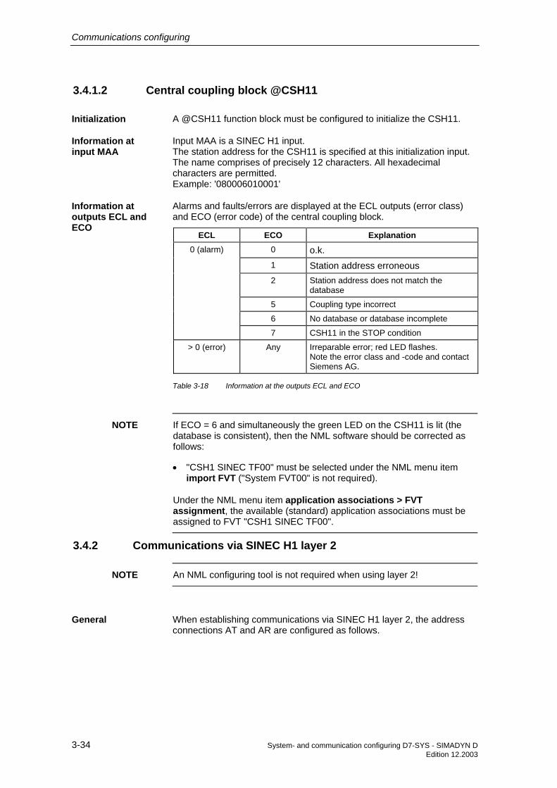
Communications configuring
3-34 System- and communication configuring D7-SYS - SIMADYN D Edition 12.2003
3.4.1.2 Central coupling block @CSH11
A @CSH11 function block must be configured to initialize the CSH11.
Input MAA is a SINEC H1 input. The station address for the CSH11 is specified at this initialization input. The name comprises of precisely 12 characters. All hexadecimal characters are permitted. Example: '080006010001'
Alarms and faults/errors are displayed at the ECL outputs (error class) and ECO (error code) of the central coupling block.
ECL ECO Explanation 0 (alarm) 0 o.k.
1 Station address erroneous 2 Station address does not match the
database
5 Coupling type incorrect
6 No database or database incomplete
7 CSH11 in the STOP condition
> 0 (error) Any Irreparable error; red LED flashes. Note the error class and -code and contact Siemens AG.
Table 3-18 Information at the outputs ECL and ECO
NOTE If ECO = 6 and simultaneously the green LED on the CSH11 is lit (the database is consistent), then the NML software should be corrected as follows:
• "CSH1 SINEC TF00" must be selected under the NML menu item import FVT ("System FVT00" is not required).
Under the NML menu item application associations > FVT assignment, the available (standard) application associations must be assigned to FVT "CSH1 SINEC TF00".
3.4.2 Communications via SINEC H1 layer 2
NOTE An NML configuring tool is not required when using layer 2!
When establishing communications via SINEC H1 layer 2, the address connections AT and AR are configured as follows.
Initialization
Information at input MAA
Information at outputs ECL and ECO
General

Communications configuring
System- and communication configuring D7-SYS - SIMADYN D 3-35 Edition 12.2003
When establishing communications via layer 2, the channel name and address stage 1 must always be specified at the address connection. When transmitting, address stage 2 must be specified. When receiving, address stage 2 information is optional.
Special features when entering data at address connection AT, AR when using SINEC H1 layer 2:
Please enter in the following sequence: "Channel name.address stage 1.address stage 2"
• Channel name
− maximum 8 characters
− ASCII characters except "Point" and @
− the channel name at a data interface must be unique.
− the channel name does not have a specific significance for SINEC H1 layer 2.
• Enter "." after the channel name
• Address stage 1: "#2-ll"
− #2- Reserved ID when using SINEC H1 layer 2.
− ll Local Link Service Access Point (LLSAP). The LLSAP consists of two hexadecimal numbers and must be divisible by four. 00 and 08 are not permitted. Each LLSAP can be simultaneously used bidirectionally - i. e. transmitting and receiving. Either one AT (transmit channel) and AR connection (receive channel) can use the same LLSAP or one US connection (transmit and receive channel).
• Enter "." after address stage 1
• Address stage 2: "Station address-rr"
− must be available when transmitting and for bidirectional channels (US connection). When receiving, the entry is optional.
− station address Specify the station address (twelve hexadecimal numbers) of the communications partner.
− - The hyphen must be specified to separate the station address and RLSAP.
− rr Remote Link Service Access Point (RLSAP). The RLSAP consists of two hexadecimal numbers, and must be divisible by four. 00 and 08 are not permitted.
Data entries at address connections AT, AR

Communications configuring
3-36 System- and communication configuring D7-SYS - SIMADYN D Edition 12.2003
NOTE • If address stage 2 is configured for the receiver, then only telegrams from the thus specified communications partner are accepted.
• If address stage 2 is not configured for the receiver, then all telegrams, specified by address stage 1, are accepted at the LLSAP ("open" LLSAP).
• AT- 'Send.#2-44.0800060100AA-12'
− transmits to partner with station address 0800060100AA, at its LLSAP 12, via LLSAP 44
• AR- 'Empf.#2-44.0800060100AA-12'
− receives via the same route, as for the example for AT
• AR- 'Empf2.#2-48'
− receives via an open LLSAP 48
• US- 'Service.#2-20.080006010002-20'
− receives and transmits via LLSAP 20
In the example, the LLSAP 44 is simultaneously used from a transmitter and a receiver, i. e. bidirectional.
NOTE • When transferring data, it should be observed that the lengths for the transmitters and receivers communicating with one another coincide. Otherwise data transfer is "transparent", i. e. the CSH11 transfers all data unchecked.
• Word (2 bytes) and double word(4 bytes) quantities are transferred in the Little-Endian format, i. e. the least significant byte at the beginning and then the most significant byte. When communicating with devices which deposit data in the Big-Endian format, then the user must adapt appropriately (e. g. for SIMADYN D using the SWB... conversion blocks).
3.4.3 Communications via SINEC H1 layer 4
NOTE The data transfer connections must be configured using the NML configuring tool. Additional information on the NML configuring tool, refer to the User documentation "SINEC NML - CP141x, CP1470".
When communicating via SINEC H1 layer 4, the address connections AT and AR are configured as follows.
Examples for data entries at the address connection
General

Communications configuring
System- and communication configuring D7-SYS - SIMADYN D 3-37 Edition 12.2003
For layer 4 communications, the channel name and address stage 1 must always be specified at the address connection. Address stage 2 is not used.
Special features for data entries at the address connections AT, AR, US when using SINEC H1 layer 4:
Input sequence: "Channel name.address stage 1"
• Channel name
− max. 8 characters
− ASCII characters except "Point" and @
− the channel name at a data interface must be unique.
− the channel name does not have a specific significance for SINEC H1 layer 4.
• Enter "." after the channel name
• Address stage 1: "#4data transport connection name"
− #4 Reserved ID when using SINEC H1 layer 4.
− data transport connection name Max. 12 characters. The symbolic name refers to a data transport connection configured with NML. The data transport connection name is the only assignment between the SIMADYN D software and the NML software. Each data transport connection can be bidirectional, i. e. transmitting and receiving can be simultaneously used. Either one AT (transmit channel) and AR connector (receive channel) or precisely one US connector (transmit and receive channel) can refer to a data transport connection.
• AT- 'Send.#4TRAVERB1'
− transmits via a data transport connection "TRAVERB1"
• AR- 'Empf.#4TRAVERB1'
− receives via a data transport connection "TRAVERB1"
• US- 'Service.#4TRAVERB2'
− receives and transmits via "TRAVERB2"
In the example, the data transport connection "TRAVERB1" is simultaneously used by a transmitter and a receiver, i. e. bidirectional.
Data entries at address connections AT, AR, US
Examples for entries at the address connection

Communications configuring
3-38 System- and communication configuring D7-SYS - SIMADYN D Edition 12.2003
NOTE • When transferring data, it should be observed that the lengths for the transmitters and receivers communicating with one another coincide. Otherwise data transfer is "transparent", i. e. the CSH11 transfers all data unchecked.
• Word (2 bytes) and double word(4 bytes) quantities are transferred in the Little-Endian format, i. e. the least significant byte at the beginning and then the most significant byte. When communicating with devices which deposit data in the Big-Endian format, then the user must adapt appropriately (e. g. for SIMADYN D using the SWB... conversion blocks).
3.4.4 Communications via SINEC H1 layer 7 (STF)
Communications via SINEC H1 layer 7 is configured at address connections AT and AR.
NOTE • The application associations are configured using the NML configuring tool. Further information on the configuring tool NML, refer to the User documentation "SINEC NML - CP141x, CP1470".
• When accessing defined complex STF variables (arrays, structures) defined in SIMADYN D, it is only permissible to access complete variables; partial access is not possible!
3.4.4.1 Address connections
Special features when making data entries at address connections AT and AR when using SINEC H1 layer 7 (STF):
Input sequence: "Channel name.address stage 1. address stage 2"
General
Data entries at address connections AT, AR

Communications configuring
System- and communication configuring D7-SYS - SIMADYN D 3-39 Edition 12.2003
• Channel name
− max. 8 characters
− ASCII characters with the exception of "Point" and @
− the channel name on a data interface must be unique.
− the channel name does not have a specific significance for SINEC H1 layer 7.
• If address stage 1 and address stage 2 are not specified, then SIMADYN D is a server as far as the associated STF utility is concerned and defines a local variable. The channel name is part of the associated variable name.
• Enter "." after the channel name
• Address stage 1
− can only be used in conjunction with address stage 2.
− max. 14 characters.
− if address stage 1 and 2 are used, SIMADYN D is a client as far as the associated STF utility is concerned.
− address stage 1 is interpreted as symbolic name of the application association, via which the STF utility is handled. Application associations are configured with SINEC NML; they define the communication paths between the applications. The application association name is the only assignment between the SIMADYN D software and the NML software.
• Address stage 2
− max. 20 characters.
− address stage 2 is the remote variable name for the communications partner (server).
If SIMADYN D is a server regarding an STF utility, then SIMADYN D defines a variable. The variable name has the following structure:
"Channelnamesubracknamepd"
• Channel name Channel name as configured at AT, AR, US (refer to the Chapter Connections of the communication blocks). It is precisely 8 characters long. If the configured channel name is shorter, then it is made up to 8 characters using "_".
• Subrack name Name of the subrack in which the SIMADYN D utility is configured. It is precisely 6 characters long. If the configured name is shorter, then it is made up to 6 characters using "_".
STF variable name

Communications configuring
3-40 System- and communication configuring D7-SYS - SIMADYN D Edition 12.2003
• p Number of the CPU on which the SIMADYN D utility is configured. Possible values: 1...8
• d Identification code for a SIMADYN D utility. This utility sets-up an object. Possible values:
− P: For process data
− M: For the message system
NOTE Using the STF utility "Interrogate name list", a client which has been removed can interrogate a list of the configured SIMADYN D utilities. The client receives information about the structure of the objects and how these objects are to be handled.
3.4.4.2 Communications utility, process data
Process data is transferred via SINEC H1 layer 7 (STF) by reading and writing data. SIMADYN D can be both a server as well as a client (CFC configuring). Process data have an open structure as far as SINEC H1 is concerned.
• The channel name is specified at connection AR of the receive block. A remote client can execute the STF utility "Write" on this variable.
• The channel name is specified at connection AT of the transmit block. A remote client can execute the STF utility "Read" on this variable.
• The SIMADYN D utility ID at the end of the variable name is "P".
Address examples:
1. Subrack "BGT1", CPU No. 3, function block CRV is to be configured: − AR- 'PZDWRITE'
− thus, the following variable name is obtained: PZDWRITEBGT1__3P
− the variable can be written into.
2. Subrack "BGT3", CPU No. 7, function block CTV is to be configured: − AT- 'PZDREAD'
− thus the following variable name is obtained: PZDREAD_BGT3__7P
− the variable can be read.
• The channel name, address stage 1 and address stage 2 are specified at connection AT of the transmit block. SIMADYN D executes the STF utility "Write" on the remote variable.
General
STF utility with SIMADYN D as server
STF utility with SIMADYN D as client

Communications configuring
System- and communication configuring D7-SYS - SIMADYN D 3-41 Edition 12.2003
• The channel name, address stage 1 and address stage 2 are specified at connection AR of the receive block. SIMADYN D executes the STF utility "Read" on the remote variable.
• The addressed variable must be defined for the communications partner.
Address examples:
1. Entry at function block CTV: − AT: "PZD1.APPLBEZ1.PZDEMPF"
− SIMADYN D writes into the remote variable, with the name "PZDEMPF" via the application association "APPLBEZ1".
2. Entry at function block CRV: − AR: "PZD2.APPLBEZ2.PZDREAD_BGT3__7P"
− SIMADYN D reads the remote variable, with the name "PZDREAD_BGT3__7P" via the application association "APPLBEZ2".
The structure of the process data objects is derived from the CFC configuring of the "virtual connections" (refer to the Chapter Communications utility, process data).
The SIMADYN D data types are converted into STF data types using the following table:
SIMADYN D data type STF data type Integer Integer16
Double Integer Integer32
Bool, Byte Unsigned8
Word Unsigned16
Double Word Unsigned32
Real, SDTIME Floating-Point
Table 3-19 Converting SIMADYN D data types into STF data types
• If precisely one connection is assigned for each transmit/receive block, then a basic STF variable is defined.
• If several connections, with the same STF data type, are assigned to each transmit/receive block, then an "Array" data type is defined. The number of array elements precisely corresponds to the number of connections.
• If several connections with different STF data types are assigned to each transmit/receive block, then a "Structure" data type is defined. The number of structure elements precisely corresponds to the number of connections.
STF variable structures

Communications configuring
3-42 System- and communication configuring D7-SYS - SIMADYN D Edition 12.2003
Combination of arrays and structures (nesting level > 1) is not possible for SIMADYN D CSH11.
NOTE The variable structure, expected from the client must coincide with that defined for the server.
3.4.4.3 Communications utility, message system
Messages are transferred via SINEC H1 layer 7 (STF) by reading and writing data. SIMADYN D can act as both server and client (CFC configuring). Messages have a structure which is open as far as SINEC H1 is concerned.
• The channel name is specified at connection AT of the message output block MSI.
• A remote client can execute the STF utility "Read" on this variable.
• The SIMADYN D utility ID at the end of the variable name is "M".
• The communications partner must read the object at specific intervals using the STF utility "Read". If a message was output via a message output block, the "Read" utility will positively respond and return this message, otherwise the response is negative.
Address example
• The configuring is to be in subrack "BGT1", CPU No. 3, function block MSI:
− AT- 'MELD'
− the following variable name is obtained: MELD____BGT1__3M
− the variable can be read.
• The channel name, address stage 1 and address stage 2 are specified at connection AT of the message output block.
• The addressed variable must be defined at the communications partner.
• SIMADYN D executes the STF utility "Write" on the remote variable.
• SIMADYN D writes into the remote variable each time that the message output block outputs a message.
Address example:
• Entry at function block MSI:
− AT: "MELD.CHEF.EINGANGSKORB"
General
STF utility with SIMADYN D as server
STF utility with SIMADYN D as server

Communications configuring
System- and communication configuring D7-SYS - SIMADYN D 3-43 Edition 12.2003
− SIMADYN D writes into the remote variable, with the name "EINGANGSKORB" via the application association "CHEF".
The STF structure of the variables is derived when CFC is used to configure the message output block MSI; and more specifically from the data entries at connections SNV, STM, SSF (refer to the Chapter, communications utility, message system). Message variables always have a complex "Structure" data type.
NOTE The STC connection at message output block MSI must be set to "1".
SSF=1 (standardized format) Contents Message structure STF structure
Spontaneous ID Unsigned8 Unsigned8
Sequence number Unsigned8 Unsigned8
Message type description
1 Octet Octet-String 2
Message type 1 Octet
Only available, Prefix Floating-Point Floating-Point
if SNV=1 Suffix Floating-Point Floating-Point
Measured value Floating-Point Floating-Point
Measured value dimension text
8 characters Visible-String 32 (if STM=0); Visible-String 92 (if STM=1)
Message instant 24 characters
Only available, if STM=1
Message text 60 characters
Table 3-20 Message structure for SSF=1
SSF=0 (hexadecimal format) Contents Message structure FMS structure
Spontaneous ID Unsigned8 Unsigned8
Sequence number Unsigned8 Unsigned8
Message type description
1 Octet Octet-String 2
Message type 1 Octet
Only available, Prefix Unsigned16 Unsigned16
if SNV=1 Suffix Unsigned16 Unsigned16
Measured value normalization factor
Unsigned32 Unsigned32
Measured value 4 Octets Octet-String 6
Measured value connector type
2 Octets
STF variable structure

Communications configuring
3-44 System- and communication configuring D7-SYS - SIMADYN D Edition 12.2003
SSF=0 (hexadecimal format) Measured value
dimension text 8 characters Visible-String 8
Message instant Time and Date Time-Of-Day (6 bytes)
Only available, if STM=1
Message text 60 characters Visible-String 60
Table 3-21 Message structure for SSF=0
NOTE The variable structure, expected from the client must coincide with that defined for the server.
3.4.5 System time
The CSH11 can be used as source for the SIMADYN D system time. The prerequisite is a SINEC time transmitter. The RTCM function block must be configured to distribute the time.
Further information on the function block RTCM, refer to the user documentation "SIMADYN D, function block library".
3.4.6 Data quantities, sampling times
Max. number / max. data quantity / sampling time
Number of SIMADYN D channels (low amount of net data) with MM4 communications buffer module
Approx. 400
Number of SIMADYN D channels (2048 bytes net data) with MM4 communications buffer module
29
Channel length (net data) 2048 bytes
Number of data transfer connections • A maximum of 46 per transmitter and per receiver from SIMADYN D can use
layer 4 of the CSH11.
46 (CP1470
characteristics)
Fastest layer 4 sampling time (up to max. 512 bytes) • If, for example, 15 transmitters are configured, then the transmitters should
be configured in a sampling time greater than 15 x 10 ms = 150 ms. The sampling time of the receiver should be shorter, as, when communicating via layer 4, the initiative always comes from the transmitter.
• Receivers should be configured in a shorter sampling time than the associated transmitter (in the "Handshake" mode). If the transmitter and receiver are configured in the same sampling time and with the "Handshake" mode, then connections are automatically and continuously interrupted. Explanation: As the transmitter and receiver are not synchronized via SINEC H1, sometimes CP1470 can receive data at the receiver side but the associated SIMADYN D receive channel was still not read-out. In such a situation, CP1470 interrupts the connection (with the intention to flag the transmitter that the data was not able to be sent to the receiver; layer 4 does
10 ms
SIMADYN D system time

Communications configuring
System- and communication configuring D7-SYS - SIMADYN D 3-45 Edition 12.2003
Max. number / max. data quantity / sampling time
not have any other acknowledge mechanism (handshake mechanism)!).
Table 3-22 Data quantities, sampling times
3.4.7 NML network management
The configuring tool NML is required to configure the data transport connections and application associations, Order No. 6GK 1740-0AB00-0BA0.
Further information on the NML configuring tool, refer to the user documentation "SINEC NML - CP141x, CP1470".
• When configuring for layer 2 or layer 4, the "CSH11_E4_2000" profile should be used. If this is not available for the NML version supplied, then please contact Siemens AG who will then provide you with it.
− profiles to be imported: "Mgt-Tbez.", "e4_handshake"
− function distribution table to be imported: "CSH1 SINECTF00".
• For layer 4 operation, data transport (data transfer) connections must be configured. The "e4_handshake" is recommended as profile.
• Both layer 2 as well as also layer 4 operation must be assigned to the existing (standard) application associations of FVT "CSH1 SINEC TF00", under the menu item "Application associations" "FVT assignment"..
General information
Configuring

Communications configuring
3-46 System- and communication configuring D7-SYS - SIMADYN D Edition 12.2003
3.5 PROFIBUS DP coupling
The following hardware and software are additionally required to configure and run the PROFIBUS DP coupling:
• COM PROFIBUS Order No. 6ES5 895-6SE12
• SS52load SS52load is included in COM PROFIBUS from V3.1.
• DP-capable PC card to download the COM database via COM PROFIBUS
SIMADYN D has the following characteristics on PROFIBUS DP:
• Master The SS52 communications module can be operated on PROFIBUS both alone (stand alone) and with other masters in multi-master operation.
• Slave In addition to the master functionality, there is also the slave functionality. Both of these functionalities can be used simultaneously or separately.
• Shared input Each slave connected to PROFIBUS DP is assigned just one master (the parameterizing master) and at first can only communicate with this master. Additional masters can read the slave input data using the ”Shared input”. SIMADYN D supports this functionality as master and slave.
• SYNC and FREEZE The outputs/inputs of several slaves can be read/written in synchronism using the SYNC and FREEZE utilities. SIMADYN D supports these utilities as master.
• Data lengths A maximum of 244 bytes can be transferred in each direction and for each slave.
• Data transfer times For short telegrams (up to 32 byte), only the SIMADYN D sampling time and the DP bus circulating time are included in the data transfer time. For longer telegrams, the software processing times of the SS52 communications module must also be included (max. 5 ms).
• Consistency Data within a telegram is always consistent.
Additionally required hardware and software
Characteristics

Communications configuring
System- and communication configuring D7-SYS - SIMADYN D 3-47 Edition 12.2003
Master1:SIMATIC
Master2:SIMADYN D
Slave 1:ET200
Slave 2:ET200
Slave 3:Drive
Slave 4:Drive
(1)
(2)
Master system 1: Master system 2:
Fig. 3-14 Multi-master system with slave functionality (1) and shared input (2)
3.5.1 Configuring with D7-SYS
The following function blocks must be configured for a PROFIBUS DP coupling:
• A central coupling block @CSPRO
• A maximum of one transmitter- and receiver function block per slave station
• Maximum of one synchronizing function block SYNPRO can be configured
• A maximum of one diagnostics function block DIAL2A can be configured
The following communication utilities are permitted:
• Process data
• Parameter processing of variable-speed drives
Permitted data transfer mode:
• Refresh
• For receivers, optionally also multiple
3.5.1.1 Central coupling block
The baud rate and PROFIBUS address are specified, on one hand by CFC (function block @CSPRO) and on the other hand by COM
Function blocks
Communications utility
Data transfer mode
Baud rate and PROFIBUS address

Communications configuring
3-48 System- and communication configuring D7-SYS - SIMADYN D Edition 12.2003
PROFIBUS. The following must be observed regarding the validity of these two parameters:
• If a COM database has still not been loaded, then
− the parameters specified by CFC are valid.
− the SS52 communications module waits for a COM database to be downloaded.
• If a COM database is loaded and the baud rate and PROFIBUS address are the same as those configured with the CFC, then
− the COM database is activated.
− communications module SS52 starts with net data transfer.
• If a COM database is loaded, but the baud rate or PROFIBUS address does not coincide with that configured in CFC, then
− the parameters specified by CFC are valid.
− the module waits for download. (the existing COM database can also be activated, by correcting the baud rate and PROFIBUS address at the central block of the COM configuring.)
3.5.1.2 Address connections AT, AR
Special features when making data entries at address connection AT, AR when using PROFIBUS DP:
Input sequence: "Channelname.Adressstage1.Addressstage 2"
• Channel name
− max. 8 characters
− ASCII characters except "Point" and @
− channel names of all transmit- and receive blocks, which access the same SS52 communications module must be different (exception for the "Multiple" data transfer mode).
− the channel name has no special significance for PROFIBUS DP.
• Input "." after the channel name
• Address stage 1:
− the slave PROFIBUS address is specified as address stage 1.
− the slave PROFIBUS address may only assigned once for each transmit- and receive channel.
− value range: 0, 3 - 123
Entries at address connection AT, AR

Communications configuring
System- and communication configuring D7-SYS - SIMADYN D 3-49 Edition 12.2003
− 0: means that this channel itself is used as slave channel and can be addressed from another master.
− 3...123: addressing external slaves.
• Enter "." after address stage 1
• Address stage 2:
− consists of a maximum of 2 characters.
− 1st character: Byte order "1": Standard PROFIBUS setting The data are transferred in the ”Motorola format” (most significant byte before the least significant byte). ”0”: Exception setting The data are transferred in the ”Intel format” (least significant byte before the most significant byte). This setting can be used for communication partners whose internal data administration uses the Intel format (e. g. SIMADYN D).
− 2nd character: Optional, only receiver "R": The access is realized as second master which reads data. ”R” can only be entered for receive channels. (”Shared input”) If a 2nd character is not specified, then the slave can be accessed as parameterizing master.
• AT- 'Setpoint.25.1'
− the channel with the name setpoint transmits data to a slave with the PROFIBUS address 25.
• AR- 'RECEIVE.117.0'
− the channel with the RECEIVE name receives data from a slave with PROFIBUS address 117. As an exception, data are transferred in the Intel format.
• AR- 'Input.33.1R'
− the channel with the name input receives data from a slave with PROFIBUS address 33 as (second) master which reads data.
• AT- 'Slavelst.0.1'
− the channel with the name slavelst transmits data as slave to a DP master.
3.5.1.3 SYNC/FREEZE commands
Examples for entries at the address connection
General

Communications configuring
3-50 System- and communication configuring D7-SYS - SIMADYN D Edition 12.2003
The SYNC and FREEZE commands synchronize the inputs and outputs of a group of slaves. The SYNPRO function block initiates these commands and supports the consistency checking process.
The configuring engineer is responsible in guaranteeing that data is consistent. For the SYNC/FREEZE command, this involves consistency of data via all of the slaves involved. It goes without saying that the consistency of the input or output data of a slave is always guaranteed.
After initiating a SYNC command, the DP master (SS52) waits for one DP bus circulating time, so that all of the slaves have received the new output values. The DP master then sends a SYNC broadcast telegram to the configured slave group. All slaves of this group then simultaneously update their buffered outputs.
Ensuring data consistency: When configuring, it must be ensured that during a DP bus circulating time, after a SYNC command has been initiated, that the SIMADYN D CPUs do not change the data.
After initiating a FREEZE command, the DP master immediately transmits a FREEZE broadcast telegram to the configured slave group. All of the slaves of this group then simultaneously read their inputs and buffer them. This input data is then available for the SIMADYN D CPUs after a DP bus circulating time has expired.
Ensuring data consistency: By suitably configuring, it should be ensured that during a DP bus circulating time, after the FREEZE command has been initiated, that the input data are not evaluated by the DP master.
3.5.1.4 Configuring versions of SYNC/FREEZE
The terminology involved with securing data consistency are explained and various configuring versions of SYNC/FREEZE are illustrated.
• Bus circulating time Cycle, in which the DP master (SS52) addresses all of the slaves once. In multi-master systems, all of the masters poll their slaves. The bus circulating time is configured using COM PROFIBUS using the baud rate, number and type of the slaves, and is computed by COM PROFIBUS. It can be read-out there using the menu command Bus parameters, as ”Typical data cycle time”.
• Sampling time This is the cycle in which the SYNPRO function block and the transmit- and receive function blocks (on SIMADYN D CPUs) are calculated. The sampling time is configured using CFC.
NOTE Bus circulating time and sampling time are independent of one another.
Consistency
SYNC
FREEZE
General
Terminology

Communications configuring
System- and communication configuring D7-SYS - SIMADYN D 3-51 Edition 12.2003
• Synccycle Synccycle is a multiple integer of the sampling time. It can be configured at input CNX of function block SYNPRO. (Synccycle=CNX x sampling time). A Synccycle always starts with a sampling time. A synchronizing command is always initiated by the SYNPRO function block in the system mode at the start of a sampling time.
Configuring version 1 corresponds to most of the applications:
• Generating SYNC commands.
• The data consistency over all slaves is guaranteed.
• The Synccycle is at least twice as long as the sampling time (CNX>1).
− the length of the transmit telegrams (outputs) for each slave may not be greater than 32 bytes.
− all transmit blocks and the SYNPRO function block must be configured in the same sampling time.
− the SYNPRO function block must be configured before all of the transmit blocks (sequence of execution).
− output SOK of function block SYNPRO must be connected with the enable inputs of all transmit blocks (belonging to a slave group).
− the bus circulating time must be shorter than the Synccycle minus 1 x sampling time. When operational, it should be checked as to whether the SOK output goes to “1“ once in each Synccycle, otherwise the Synccycle should be increased.
Example:
• Synccycle=3 x sampling time
• Bus circulating time=2 x sampling time
• Assumption: The SYNPRO function block calculates at the center of the sampling time (before all transmit blocks)
Sampling time
Synczyklus
Bus circulatingtime
Output SOK10
(1) (2) (3) (1) (2) (3)
SYNC_command
SYNC_quit
SYNC_command
SYNC_quit
SYNC_command
Fig. 3-15 Timing diagram, SYNC version 1
Configuring version 1

Communications configuring
3-52 System- and communication configuring D7-SYS - SIMADYN D Edition 12.2003
When initiating the SYNC command, the transmit blocks are inhibited (SOK=0) for two sampling times (one bus circulating time). The transmit blocks are enabled in the third sampling time after initiating the SYNC command (SOK=1).
Configuring version 2 has the highest SYNC performance:
• Generating SYNC commands.
• The data consistency over all slaves is guaranteed.
• Synccycle=sampling time (CNX=1)
− the length of the transmit telegrams (outputs) for each slave may not be greater than 32 bytes.
− all transmit blocks and the SYNPRO function block must be configured in the same sampling time.
− high baud rate (>1.5 Mbaud). For lower baud rates, the time conditions can hardly be maintained.
− the bus circulating time may only be a maximum of 50 % of the sampling time.
− the bus circulating time must also be so low, that one sampling time expires from the start up to the calculation of the function block SYNPRO. This cannot be guaranteed, but must be checked when the system is operational.
Example:
• Synccycle=sampling time
• Bus circulating time=0,3 x sampling time
• Assumption: The SYNPRO function block calculates at the center of the sampling time (before all transmit blocks)
Sampling time
Synczyklus
Bus circulatingtime
Input SOK10
SYNC_command
SYNC_quit
SYNC_command
SYNC_quit
SYNC_command
FB-SYNPRO FB-SYNPRO
(FB-SYNPRO is calculating too early)
Fig. 3-16 Timing diagram, SYNC version 2
Configuring version 2

Communications configuring
System- and communication configuring D7-SYS - SIMADYN D 3-53 Edition 12.2003
Normally, the transmit blocks are always enabled (SOK=1). If, due to time fluctuations, the SYNPRO function block is calculated before SYNC has expired (to the right in the diagram), the transmit data are not updated, but the values from the previous sampling time are transferred. The Synccycle and the data consistency are not influenced.
Instructions to achieve good SYNC functionality:
In addition to a low Synccycle, it is also necessary to have the lowest amount of jitter (time-based fluctuations) in the Synccycle. The following measures support this:
• Irregular data transfer along the DP bus should be prevented: Single-master operation; stations must not be temporarily switched-in.
• Alarm tasks should not be configured on the same SIMADYN D CPU. Sampling time overruns are not permissible; this would result in a SYNC command failure or a shift by a complete sampling time.
• Configure a high baud rate and short telegram lengths (the time to poll a slave is included in the jitter.).
• Configure the SYNPRO function block and all associated transmit blocks in T1=T0 (basic sampling time). The SYNC command is always initiated with the basic clock cycle interrupt. It is received with more accuracy (timing accuracy) as an interrupt, initiated in the system mode.
Configuring version 1 (3) is for generally less frequently used applications of FREEZE:
• Generating SYNC and FREEZE or only FREEZE commands.
• The data consistency over all slaves is guaranteed.
• The Synccycle is at least 300 % longer than the sampling time (CNX>1).
− the length of the transmit- or receive telegram (inputs or outputs) may not exceed 32 bytes per slave.
− all transmit- and receive blocks and the SYNPRO function blocks must be configured in the same sampling time (on the same CPU).
− the SYNPRO function block is configured as the last function block in the processing sequence.
− output SOK of function block SYNPRO should be connected with the enable inputs of all (belonging to the slave group) transmit- and receive blocks.
• The bus circulating time must be less than the Synccycle minus 2 x the sampling time. When the system is operational, it should be checked whether the SOK output goes to “1“ once per Synccycle; otherwise the Synccycle should be increased.
Configuring version 3

Communications configuring
3-54 System- and communication configuring D7-SYS - SIMADYN D Edition 12.2003
Example:
• Synccycle=4 x sampling time
• Bus circulating time=2 x sampling time
• Assumption: The SYNPRO function block calculates at the center of the sampling time (after all of the receive- and transmit blocks)
Sampling time
Synczyklus
Bus circulatingtime
Output SOK10
(1) (2) (3) (4) (1) (2)
SYNC_command
SYNC_quit
SYNC_command
(4)
Fig. 3-17 Timing diagram SYNC version 3
After the SYNC command has been initiated, the transmit- and receive blocks are inhibited for three sampling times (one bus circulating time + one sampling time) (SOK=0). The transmit- and receive blocks are enabled in the fourth sampling time after the SYNC command has been initiated (SOK=1).
3.5.1.5 Diagnostics function block
Master- or slave-specific diagnostic information can be output from PROFIBUS DP using the DIAPRO function block.
The diagnostic data to be output are selected using input SEL. It is output at D01 to D08.
Further information on the diagnostic data, refer to the User Documentation "COM PROFIBUS" or in the User Documentation for the individual slaves.
SEL=0: No diagnostic data
• The block does not output any valid diagnostic data.
SEL=126: System diagnostics
• The system diagnostics provides an overview as to which slave has provided diagnostic data.
General
Overview, diagnostic data

Communications configuring
System- and communication configuring D7-SYS - SIMADYN D 3-55 Edition 12.2003
• The 8 words are bit-coded.
• Each bit is assigned a slave with its PROFIBUS address corresponding to the following table.
• If the bit for the associated slave is set, then the slave has provided diagnostics data.
Output Bit 16 Bit 15 Bit 14 ... Bit 5 Bit 4 Bit 3 Bit 2 Bit 1 D01 15 14 13 ... 4 3 (2) (1) (0)
D02 31 30 29 20 19 18 17 16
... ... ...
D07 111 110 109 100 99 98 97 96
D08 - - (125) ... 116 115 114 113 112
Table 3-23 Assigning system diagnostics/data transfer list to the slave PROFIBUS address
SEL=127: Data transfer list
• The data transfer list provides an overview of the slaves which were involved with data transfer within a configured time (COM PROFIBUS).
• The 8 words are bit-coded as for the system diagnostics.
• If the bit for the assigned slave is set, then data is being transferred.
SEL=128: Master status
• Outputs information specific to the master (for users, the low byte of D01 is relevant; the significance of the other outputs has been documented, but hasn’t been explained in any more detail):
Output Significance D01 low byte Status of the DP master: Stop (40h), Clear (80h),
Operate (C0h)
high byte Ident No. SS52 (high byte)=80h
D02 low Ident No. SS52 (low byte)=37h
high (irrelevant)
D03...D08
Table 3-24 Information specific to the master
SEL=3 ... 123: Slave diagnostics
• Output of slave diagnostics data.
• The SEL data entry corresponds to the slave PROFIBUS address.

Communications configuring
3-56 System- and communication configuring D7-SYS - SIMADYN D Edition 12.2003
• The diagnostics data is dependent on the slave type.
• The first 16-byte slave diagnostic data are output.
• Additional slave diagnostic data can be output with SEL>1000.
Further information on slave-specific diagnostics data, refer to the user documentation "COM PROFIBUS" and the User Documentation for the individual PROFIBUS slaves.
Slave type SPC slaves, general
ET 200U ET 200B ET 200K SPM slave
ET 200C 8DE/8DA
DP stand. slaves
Connection D01 low Status 1 Diagnostics
high Status 2 according to the
standard
D02 low Status 3 6 bytes
high Master PROFIBUS address
D03 low Identification number, high byte
high Identification number, low byte
D04 low Header, device-related diagnostics
high Device diagnostics U Device diagnos. B
0 0 0
D05 low Header identification-related diagnostics
0 0 0 0
high BG 7-0 0 Channel 7-0
D06 low BG 15-8 0 Channel 15-8 0 Device-
high BG 23-16 0 Channel 23-16 0 specific
D07 low BG 31-24 0 Channel 31-24 0 diagnostics
high Additional device-
Irrelevant
D08 low specific Irrelevant
high diagnostics Irrelevant
Table 3-25 Overview of the structure of the diagnostics data for Siemens DP slaves
Diagnostics data of SIEMENS DP slaves

Communications configuring
System- and communication configuring D7-SYS - SIMADYN D 3-57 Edition 12.2003
Bit 8 Bit 7 Bit 6 Bit 5 Bit 4 Bit 3 Bit 2 Bit 1 Status 1 (D01 low byte)
S: Slave was para-meterized from another master
S: Last parameter telegram was erroneous
M: Erroneous slave response
S: Reques-ted func-tion is not supported
S: Diagnos-tics entry in the specific diagnos-tics area
S: Config. data dont match
S: Slave still not ready for data transfer
M: Slave cannot be addressed on the bus
Status 2 (D01 high byte)
M: Slave entered as ”not active”
(not used) S: Slave has received a Sync command
S: Slave has received the Freeze command
S: Response moni-toring activated
S: 1 (fixed)
S: Diagnos-tic data must be retrieved
S: Parameterization and configuring required
Status 3 (D02 low byte)
S/M: Not all dia-gnostics data can be trans-ferred
- - - - - - -
Table 3-26 Significance of the individual bits, status 1, 2 and 3
− M: Master identifies diagnostics data
− S: Slave identifies diagnostics data
Master PROFIBUS address
• PROFIBUS address of the master which had parameterized this slave.
If this slave is not parameterized, then FFh is used.
Identification number
• High/low byte: This identifies the slave type.
All additional diagnostic data are slave-specific.
Generally (standard DP slave) the diagnostic blocks follow: Device-related, identification-related and channel-related diagnostics. Not all slave-specific diagnostic blocks must be available.
Each block is preceded by a header byte. The diagnostics block is identified by bit 7 and bit 8:
Bits, status 1, 2 and 3

Communications configuring
3-58 System- and communication configuring D7-SYS - SIMADYN D Edition 12.2003
Bit 7, 8 of the header byte Significance Bit 7, 8= 00 Device-related diagnostics
Bit 7, 8= 01 Identification-related diagnostics
Bit 7, 8= 10 Channel-related diagnostics
Table 3-27 Significance of bit 7 and bit 8 of the header byte
Bits 1 to 6 define the following:
• For device- and identification-related diagnostics the length of the diagnostic block including the header byte, value range 2...63.
• For channel-related diagnostics, the identification number, value range 0...63.
Output of additional slave diagnostics data
• Diagnostic bytes 17 to 32 of a slave are output with SEL=1002 to SEL=1123.
3.5.2 Configuring with COM PROFIBUS
COM PROFIBUS (Windows) should be used when configuring (it is also possible to use the earlier COM ET200 Version 2.1 for configuring). Using COM PROFIBUS you can define:
• The number and configuration of the nodes connected to the PROFIBUS DP bus system
• The baud rate
• Important parameters when using the PROFIBUS DP bus system
SIMADYN D-specific information on COM PROFIBUS:
• Configure the SS52 communications module as SIMADYN D SS52 station type ("SIMADYN" family).
• The input and output addresses should not be specified.
• After completing the configuring, the database is downloaded into SS52 via the DP bus using the menu command File > Export > DP master.
• Alternatively, it is also possible to download via RS232. The following menu command is used to start loading the SS52: File > Export > SIMADYN Master.
3.5.2.1 Harmonizing with data configured in CFC
The configured software should be harmonized with one another as follows:
General
Rules

Communications configuring
System- and communication configuring D7-SYS - SIMADYN D 3-59 Edition 12.2003
• The baud rate and the actual PROFIBUS address must be the same.
• The slaves, configured in COM must each have, in the receive- and transmit directions, a CRV/CTV function block configured in the CFC. This is assigned via the PROFIBUS address (address stage 1 at the address connection).
• The length of the input- (receive-) and output- (transmit-) data per slave must coincide.
The rules (syntax) are checked. Error- or alarm information is issued if these rules (syntax) are not observed:
• Communications error field (flashing "C" on the CPU module), or output YTS at function block CRV/CTV
• Output ECO at function block @CSPRO
NOTE The following rules /syntax) are not checked: The net data structure of the communication partners must be the same.
If this is not observed, the data could be incorrectly interpreted (e. g. bytes could be interchanged within a data word) between the communication partners.
For SIMADYN D, the net data structure with CFC is specified by configuring the virtual connections (refer to the Chapter Communications utility, process data).
• For most of the PROFIBUS slaves, the net data structure is specified using COM PROFIBUS by entering identification codes in the "Configuring" window.
3.5.2.2 SS52 as PROFIBUS slave
The SS52 communications module can be configured as pure slave or combined as master and slave:
• SS52 as pure slave does not require COM to be configured: Input SLA should be set to 1 or 2 at function block @CSPRO. A function block CRV and/or CTV should then be configured next to it. The address stage 1 at connection AR/AT should be set to "0".
• SS52 combined as master and slave Input SLA at function block @CSPRO should be set to "0" (default value).
Error- and alarm information
Net data structure
Configuring

Communications configuring
3-60 System- and communication configuring D7-SYS - SIMADYN D Edition 12.2003
− The bus is configured using COM PROFIBUS. A database ("master system") is created for each PROFIBUS master. This is used to download the particular master.
− If the master is configured using another tool, when configuring the SS52 slave, a fictitious master must be configured in COM PROFIBUS. It should be ensured that the bus parameters are correctly set: It is recommended to increase the number of active stations and the token rotation time in both configuring tools.
3.5.2.3 Loading the database
There are two ways to load the database:
Loading via PROFIBUS DP
• Loading via PROFIBUS DP is the version which is the more user friendly. However, certain restrictions must be observed.
• A DP-capable PC card is required (currently available cards can be requested from the product support)
• The driver for the PC card is installed together with COM PROFIBUS. Loading is realized in COM PROFIBUS using the menu command File > Export > DP master.
Loading via RS232
• Using the "SS52LOAD" program, a database, generated from the COM PROFIBUS is loaded as binary file into the SS52 module via the RS232 interface.
• SS52LOAD is integrated in COM PROFIBUS (from Version 3.1).
• Restriction: If the Sync function block SYNPRO is configured, then the synchronous mode must be disabled (enable input EN=0), so that the download functions.
• The binary file (*.2bf) is generated in COM PROFIBUS using the menu command File > Export > Binary file.
• Loading is realized with SS52LOAD with the menu command File > Download .
• The RS232 interface is located together with the PROFIBUS interface on the 9-pin connector of the SS52 module. The customer must assemble his own cable to establish the connection to the COM port of the PC. RS232 assignment at SS52 (no standard):
− 2 - TxD
− 7 - RxD
Versions

Communications configuring
System- and communication configuring D7-SYS - SIMADYN D 3-61 Edition 12.2003
!
CAUTION There is a danger of interchanging connections for the RS232 assignment.
3.5.3 Start-up/diagnostics
3.5.3.1 LEDs
Contrary to the other communication modules, for the SS52 communications module, the yellow LED does not directly indicate the bus activity.
The green LED provides general information about the SS52 communications module and about synchronization with function block @CSPRO from SIMADYN D. The yellow LED provides information about the DP bus and the COM database.
LED Green Yellow Dark CPU not running No bus operation (during run-up).
Flashes quickly (every 0.2 s)
Fatal error • Remedy: Read-out the error class and -
code at function block @CSPRO and inform Siemens AG.
Bus error (e. g. short circuit) • Remedy: Check the cable and the other
bus nodes.
Flashes (every 1 s)
Wait and synchronize to the SIMADYN D-CPU • Remedy: Check the configuring of
function block @CSPRO.
COM database not available or not activated (also during download) • Remedy: Load the database.
Flashes slowly (every 2 s)
- CFC- and COM configuring do not match 100%. Only restricted bus operation is possible • Remedy: Adapt the CFC- and COM
configuring so that they match.
Steady Communications module SS52 and synchronization to SIMADYN D CPUs OK.
Bus operation with activated COM database OK.
Table 3-28 Significance of the LEDs of the SS52 communication module
• After power-on, both diodes are briefly lit and then go dark again.
• Only the green LED is lit during the run-up time (approx. 5 seconds).
• When the system is OK, the yellow LED is lit after the run-up time has expired.
• After a reset, both LEDs initially stay in the last condition until the software again controls the LEDs.
Yellow LED
Green LED
Behavior at run-up

Communications configuring
3-62 System- and communication configuring D7-SYS - SIMADYN D Edition 12.2003
• During download, the yellow LED flashes (this is extremely short at high baud rates).
• After this, the behavior is the same as for run-up.
The LEDs do not provide information as to whether all of the slaves are available at the bus and have been correctly parameterized. If data transfer with a slave is not OK, then this is flagged at the associated function block (YEV=0x0002 or YTS=0x6014) using a ”break” ID. Information regarding the current status of individual slaves is obtained using the diagnostics function block DIAPRO.
3.5.3.2 Error class (ECL) and error code (ECO)
Significance of the outputs ECL, ECO at function block @CSPRO:
• Error class=0: An alarm is present. In some cases this alarm can be removed without a SIMADYN D reset. If there are several alarms, then the alarm of the lowest number is displayed.
• Error class>0: An error is present. Function block @CSPRO issues a communications error (flashing ”C” on the CPU module). After the error has been removed, the SIMADYN D subrack must be reset.
Characteristics at download
Outputs ECL, ECO

Communications configuring
System- and communication configuring D7-SYS - SIMADYN D 3-63 Edition 12.2003
Error class Error code Significance 0
(alarm) 0 O.K.
1 COM database present, but not activated as the baud rate and the PROFIBUS address with connections BDR and MAA do not match. • Remedy: Harmonize the baud rate and PROFIBUS address in the CFC
and COM configuring.
2 No COM database available. • Remedy: Load the database.
3 The COM database is presently being downloaded with subsequent start-up.
4 The channels to DP nodes, configured with CFC, which are configured in the COM database, are missing. This status can also temporarily occur after a SIMADYN D run-up. The DP nodes are not addressed.
• Remedy: Harmonize the CFC- and COM configuring.
5 (not used)
6 There is at least one channel configured with CFC which does not match the COM database. The associated SIMADYN D FB has issued a communications error (flashing ”C”).
• Remedy: Harmonize the CFC- and COM configuring.
7 There is at least one channel configured with CFC, which essentially does not match the COM database. The associated SIMADYN D-FB has issued a communications error (flashing ”C”).
• Correct the CFC configuring.
8 Resource bottleneck. Not all of the CFC channels are processed. • Remedy: Reduce the CFC configuring (communication channels).
9 There are two channels, which wish to transmit data to the same slave or receive data from it. The SIMADYN D-FB which is associated with the channel which addressed the slave later, has issued a communications error (flashing ”C”).
• Remedy: Correct the CFC configuring.
10 Bus operation temporarily faulted. • Remedy: Check the cable and bus nodes.
>1 (internal
error)
(any) • Remedy: Note the error class and error code and inform Siemens AG.
Table 3-29 Significance of the error class and error code
3.5.3.3 Application example, PROFIBUS DP coupling
The application example describes a typical configuration consisting of:
• SIMOVERT 6SE70
• ET200U
• ET200B
• SIMATIC S5
General

Communications configuring
3-64 System- and communication configuring D7-SYS - SIMADYN D Edition 12.2003
It is assumed that you are knowledgeable about configuring SIMADYN D as well as the CFC configuring language.
NOTE Only those activities are described in detail which are of significance for this particular configuration. Versions or additional components are touched-on but not discussed in detail. In the text, these positions are identified with the symbol located on the right.
The following subjects are discussed in this application example:
• Typical configuration Description of a typical configuration for SIMADYN D connected to PROFIBUS DP with the associated system requirements.
• Configuring under CFC Grouping of the PROFIBUS DP specific blocks and their configuring in the typical configuration.
• Configuring the SS52... communications module Configuring the SS52 communication module using the COM PROFIBUS 3.0 parameterizing software and the download tool "SS52load".
3.5.3.4 Typical configuration and system requirements
The following systems and devices are selected as typical configuration, whereby the specified PROFIBUS addresses were randomly defined:
SS 5
2
SIMADYN DSIEMENS
S 01 S 02 S 03 S 04 S 05 S 06 S 07 S 08 S 09 S 10 S 11 S 12
CS 7
SIE
MEN
S
SIE
MEN
S
SIE
ME
NS
SIEMENS SIMATIC S5
IM 3
08-C
Station 11ET 200U
Station 51ET 200B
Station 71MASTER DRIVE
Station 1Station 4
PM 5
Fig. 3-18 Typical configuration
General

Communications configuring
System- and communication configuring D7-SYS - SIMADYN D 3-65 Edition 12.2003
The SIMADYN D communication partners (station 4) are as follows:
• SIMATIC S5-105U (station 1) as master to SIMADYN D: The SS52 has a master (S5) which polls the SIMADYN D. Data transfer (quantity and amount of process data) between the two controls can be freely configured. The following was defined:
− S5 SIMADYN D: Three words (input/output), one word (input), one byte (input), one byte (input)
− SIMADYN D S5: Three words (input/output), one word (output), one byte (output)
• SIMOVERT MASTER DRIVE with CB1 (station 71) as slave: Five defined PPO types are available for data transfer with this node. PPO: Parameter process data object structure of the net data for variable-speed drives. There is net data, which either consists of parameter ID values (PKW) and process data (PZD) (PPO types 1,2,5) or only process data (PPO types 3,4). In this configuring example, PPO type 3 is configured. In this case, two words (control word and main setpoint) are transmitted and two words (status word and main actual value) received.
• ET 200 B (station 51) as slave: When using this slave type, a precise type must be selected which then automatically defines data transfer. For 8DI/8DO types, one byte is output and one byte is read-in.
• ET 200 U (station 11) as slave: For this ET 200 U configuration (three digital output modules and a digital input module) three bytes are output and one byte is read-in.
Communications partner

Communications configuring
3-66 System- and communication configuring D7-SYS - SIMADYN D Edition 12.2003
3.5.3.5 Check list of the required hardware and software components for SIMADYN D
SIMADYN DSIEMENS
S 01 S 02 S 03 S 04 S 05 S 06 S 07 S 08 S 09 S 10 S 11 S 12
Fig. 3-19 Hardware and software components for SIMADYN D

Communications configuring
System- and communication configuring D7-SYS - SIMADYN D 3-67 Edition 12.2003
1 SIMADYN D unit consisting of at least: Subrack, CPU, program memory sub-module, communications module CS 7 and communications sub-module SS52
2 CFC configuring device: PC with Windows 95/NT as operating system, STEP 7 software, option package D7-SYS and PCMCIA drive
3 PC to operate "COM PROFIBUS" and "SS52load" (this can be the same PC as for CFC), with: 3.5" floppy disk drive, one serial interface, Windows 3.1x or Windows 95 operating system
4 "COM PROFIBUS 3.0" parameterizing software: Software to generate the PROFIBUS DP bus configuration
5 Download software "SS52load": Software to transfer the DP configuration generated with "COM PROFIBUS" to SS52 via the COM port (RS 232) of a PC.
6 RS232 line: Connection between the SS52 (in the 9-pin connector of the SS52, in addition to the RS485 of the Profibus, there is also an RS232: 2-TxD; 7-RxD) and a PC COM port (RS232). This cable must be assembled according to the specifications (refer to Chapter Downloading the COM database onto the SS52) as the RS232 of the SS52 is not standard! If data is downloaded via the bus (RS 485), using a communications processor CP 5411 (additional plug-in card in the PC), then the "SS52load" tool and the RS232 line are not used. However, the CP 5411 is not included in this documentation.
Supplementary literature (for emergency situations and additional applications!):
7 User Documentation SIMADYN D
8 Manual on the COM PROFIBUS parameterizing software
9 Manuals of the other nodes: SIMATIC S5, ET 200U, ET 200B, SIMOVERT Master Drives
Table 3-30 Legend, hardware and software components for SIMADYN D
3.5.3.6 Configuring under STEP 7 CFC
In order to simplify unified configuring of a "PROFIBUS DP coupling" under CFC, the bus-specific CFC blocks are now grouped together and the relevant syntax explained.
When configuring an SS52 communications sub-module under CFC, the following should be observed:
• Precisely one central block @CSPRO must be used for each SS52 communications sub-module
Legend
General

Communications configuring
3-68 System- and communication configuring D7-SYS - SIMADYN D Edition 12.2003
• A maximum of one transmitter- and/or one receiver block per communications partner
• Permitted communication utilities:
− process data
− parameter processing of variable-speed drives
• Permitted data transfer mode: Refresh (for receivers, also multiple)
• A maximum of one synchronization function block SYNPRO per SS52 communications module
• A maximum of one diagnostics function block DIAPRO per SS52 communication module
Central block PROFIBUS DP coupling @CSPRO
ECLECOCDMQTS
----
-----
GV
II I
I
BOBO
CTSMAABDR
CS7 module name.connectorPROFIBUS address
Baud rate
Error classError codeCoupling statusBlock status
@CSPRO
SLALCC
II
Only slave functionalityHost CPU monitoring time
Fig. 3-20 Central block, PROFIBUS DP coupling @CSPRO
• Use This function block initializes and monitors the PROFIBUS DP coupling (CS7 with SS52). It may only be configured in a sampling time of 32 ms ≤ TA ≤ 255 ms.
• I/O ECL, ECO, CDM, QTS and YTS are service- and diagnostics I/O which are generally used for SIMADYN D start-up (commissioning). They are not used for configuring.
Further information on the I/O of the central block PROFIBUS DP coupling @CSPRO, refer to the User Documentation "SIMADYN D, function block library".
Function blocks

Communications configuring
System- and communication configuring D7-SYS - SIMADYN D 3-69 Edition 12.2003
CTS The configured name of the CS7 module (identical with the entry in the master program, actual: D04) and the designation of the CS7 slot where the SS52 is located (X01, X02 or X03, actual: X02) is specified at this initialization input.
MAA Just like all of the other bus nodes, the SS52 module has a station address. This must be specified at this connector (a number between 1 and 123, actual: 4).
BDR The baud rate, which the SS52 uses on the bus, is set using this connector. This value must be specified in a code: 0=9,6 kbaud ; 1=19,2 kbaud ; 2=93,75 kbaud ; 3=187,5 kbaud ; 4=500 kbaud ; 5=1,5 Mbaud ; 6=3 Mbaud ; 7=6 Mbaud ; 8=12 Mbaud ; (actual: 5).
SLA Initialization input, only for slave functionality: 0: SS52 operates as PROFIBUS master and/or slave. A COM PROFIBUS database must be loaded. 1 or 2: SS52 operates as pure PROFIBUS slave without COM PROFIBUS database 1: Slave with either inputs or outputs, 2: Slave with inputs and outputs (actual: 0)
LCC Initialization input for the time in which the SS52 module monitors the SIMADYN D host CPU: <0: No monitoring 0...10: Monitoring time=1s (default) >10: Monitoring time in 1/10 s (actual: 0)
Table 3-31 I/O of the central PROFIBUS DP coupling block
3.5.3.7 Using transmit- and receive blocks
The function blocks of the communications utility, process data must be configured for PROFIBUS DP.
The address connections AT and AR of those blocks, which access the SS52 data interface, must have the following syntax (rules):
AT/AR- 'Channelname.Addressstage1.Adressstage2'
Channel name
• Must be unique, corresponding to the general communication rules (the channel names of all transmit- and receive blocks, which access the same SS52 communications module, must be different)
• It may consist of a maximum of 8 characters
• It has no special significance for PROFIBUS DP
Address stage 1
• The PROFIBUS address of the communication partner is specified in this address stage.
• Using address 0, this channel goes to the slave and is called-up by other bus masters.
• External slaves can be addressed using addresses 3..123.
General

Communications configuring
3-70 System- and communication configuring D7-SYS - SIMADYN D Edition 12.2003
• A PROFIBUS address may only be used once for each transmit-/receive channel.
Address stage 2 This address stage is configured with one or two characters:
• 1st character: Defines the byte order to transfer word quantities for various communication partners.
− 1=Motorola format (high byte before the low byte) Thus, it corresponds to the telegram structure of the PROFIBUS standard, and should be used as standard, especially when transferring single word quantities to standard bus nodes (analog I/O, SIMOVERT, SIMATIC etc.)
− 2=Intel format (low byte before the high byte) Can be used for data transfer to devices where data is processed according to the Intel format just like in SIMADYN D (e. g. second SS52)
Coupling partner 1st character SIMOVERT Master Drives with CB 1 (standardized bus nodes)
1
ET200 distributed periphery (standardized bus nodes)
1
SIMATIC (IM 308 C,...) (standardized bus nodes) 1
SIMOREG 6RA24 1
MICRO / MIDI Master (standardized bus nodes) 1
SIMADYN D (SS52) (the coupling partner must also have the same setting)
0
Table 3-32 Byte order for various communication partners
• 2nd character (optional, only for receivers): When an "R" is entered at a receive channel, the SS52 is authorized to read other slaves (shared input).
3.5.3.8 Configuring the typical configuration in CFC
In this case, it does not just involve process data processing, but mainly in implementing the listed communication paths to the other bus nodes.
A CFC chart with explanations shows how to configure the PROFIBUS DP. The CFC chart does not purport to include all details.
The following are to be configured:
• CPU PM5 in slot S01 under the name D01_P1:
• Communications module CS7 at slot S02, designation D02
• Communication sub-module SS52 (D042) on CS7 connector X01
General

Communications configuring
System- and communication configuring D7-SYS - SIMADYN D 3-71 Edition 12.2003
"D02.X01"
Configured name of the CS7 module: D02and connector of the SS52 module: X01
Own PROFIBUS address: 4Baud rate: 5 (1,5 Mbaud)
"D02.X01"Virtual connection name, transmit
"!T_MOTO"
"D02.X01"
Virtual connection namereceive
"!R_MOTO"
Receive channel name: R_MotoSlave address: 71
Transmit channel name: T_MotoSlave address: 71
4500
'T_Moto.71.1''R'
1
'R_Moto.71.1''R'
1
CRRQTSYEV
CRV
--
---
GV
SS
BO
GVBOW
CTSARMODEN YTS I -
CTV
--
---
GV
SS
BO
GVBOW
QTSYEV
CRTCTSATMODEN YTS I -
ECLECOCDMQTS
----
----
GV
II I
I
BOBO
CTSMAABDR
@CSPRO
SLALCC
II
Fig. 3-21 CFC chart (Part 1) of the typical configuration

Communications configuring
3-72 System- and communication configuring D7-SYS - SIMADYN D Edition 12.2003
Status word:1st word from the receive telegram(virtual connection name R_MOTO)
"!T_MOTO.0001"Control word:1st word for the transmit telegram(virtual connection name T_MOTO)
"!R_MOTO.0001"
Main actual value:2nd word from the receive telegram(R_MOTO)
"!T_MOTO.0002"Main setpoint:2nd word for the transmit telegram(T_MOTO)
"!R_MOTO.0002"
Q1Q2Q3Q4Q5Q6Q7Q8Q9Q10Q11Q12Q13Q14Q15Q16
W_B----------------
W IS BOBOBOBOBOBOBOBOBOBOBOBOBOBOBOBO
YNOP1_I
-I IX
QSB_W
----------------
BO WI1I2I3I4I5I6I7I8I9I10I11I12I13I14I15I16
BOBOBOBOBOBOBOBOBOBOBOBOBOBOBO
YNOP1_I
- I IX
Fig. 3-22 CFC chart (Part 2) of the typical configuration

Communications configuring
System- and communication configuring D7-SYS - SIMADYN D 3-73 Edition 12.2003
3.5.3.9 Configuring the SS52 communications module with COM PROFIBUS
If the SS52 communications module is inserted at one of the three slots of the CS7 (currently: X01) and was configured, then values are transferred between the transmit- or receive blocks and the bus connector on the SS52 communications module. As SIMADYN D is a freely-configurable system, the following logical communication structures must be assigned:
• Bus parameters defined (baud rate, ...)
• The communication associations between the nodes defined (who communicates with whom, and in which function?)
• The communication objects must be defined (communication objects are useful (net) data. For SIMADYN D they consist of the process- and device data. However, for the typical configuration, communications only involves the process data.)
This data (in the following, designated as COM database) is saved on the SS52 in a permanently integrated memory and are changed and adapted by downloading via the 9-pin sub-D connector of the module.
3.5.3.10 Generating the COM database with COM PROFIBUS
Master and slaves of a bus structure are configured using a graphic user interface and a list of communication partners which are supported..
At the start, all communication associations of the typical configuration are defined by selecting the nodes involved.
1. After the program start, the first master system is set-up using the menu command File > New.
Fig. 3-23 Dialog box, "Master-host selection"
2. After buffering the data (File > Save under...) using any name (current: "Typical" ), a first host system is generated with the name "Mastersystem <1>". The code number (current: 1) is identical with the selected PROFIBUS address. This first step defines who has the “say“ on this host system.
General
Procedure
Parameterizing the 1st host system

Communications configuring
3-74 System- and communication configuring D7-SYS - SIMADYN D Edition 12.2003
Fig. 3-24 Window "DP master system PROFIBUS address 1"
3. After selecting the button "ET200" in the "Slaves" menu, the mouse pointer points to an empty box with an arrow upwards.
This allows slaves to be assigned to the S5 station, by positioning the mouse pointer under the station symbol and then clicking on the mouse.
4. After interrogating the PROFIBUS address (current: 4) the communications partner can be selected in an additional selection window.
Fig. 3-25 "PROFIBUS address" window

Communications configuring
System- and communication configuring D7-SYS - SIMADYN D 3-75 Edition 12.2003
― The majority of the setting possibilities in the "Slave characteristics" window are of now significance for the typical configuration. The standard settings can be used. Only the family (current: SIMADYN), the station type (current: "SS52 master/slave") and the "Configuring..." button are important.
Fig. 3-26 Dialog box, "Slave characteristics"
6. However before configuring starts, the specified settings must be acknowledged with OK in a dialog box "Master-host selection".
Fig. 3-27 Dialog box, "Master-host selection"
7. The bus node is now actually configured. For the SS52 communications module, this configuration window is at first completely empty. The net data structures must now be entered in the list in the dialog box "Configuring: SIMADYN D slave ...".
NOTE S5 is the master in this "Master system <1>" so that the transmit- and receive mode must be considered from its perspective (I/O addresses of the S5).

Communications configuring
3-76 System- and communication configuring D7-SYS - SIMADYN D Edition 12.2003
Fig. 3-28 Dialog box, "Configuring: SIMADYN D slave ..."
8. All of the data types are entered in the "ID" column. In this case, the associated dialog box must be activated. You can achieve this by either double clicking on a cell, or after highlighting the cell, depressing the "ID" button. The following parameters can now be specified:
• Type Select between:
− input, output
− input/output
− empty location
− special format
• Length 1 to 16
• Format Select either single-word- or byte format
Fig. 3-29 Dialog box, "ID"

Communications configuring
System- and communication configuring D7-SYS - SIMADYN D 3-77 Edition 12.2003
9. After terminating the dialog with OK, the appropriate ID is entered in the list. The sequence of the process data in the telegram is defined by the position at which the ID is entered in the input or output address ranges (fields with a grey background are not taken into account). Entries into the comments column are optional and can be freely configured. The address settings ("I-Adr." and "O-Adr.") are not required for the SIMADYN D database. Thus, the first host system has been generated in which the SIMADYN D is slave to the S5. Parameterization has now been completed. It should be observed, that this involves the configuring data for the IM308 (S5); therefore these no longer have to be processed, as they are not relevant for the SS52.
Fig. 3-30 Window, "DP master system PROFIBUS address 1"
1. The first host system is closed by double clicking on "Master 4" and the second host system is made accessible so that the SS52 master can be parameterized.
Fig. 3-31 Dialog box, "Overview, master systems"
Parameterization of the 2nd host systems

Communications configuring
3-78 System- and communication configuring D7-SYS - SIMADYN D Edition 12.2003
2. By double clicking on the symbol "SIMADYN D" it can be seen how important it is to first set-up the SS52 as slave in the "Host system <1>". The complete telegram structure is automatically transferred into the SS52 configuration with the difference that the telegrams lie interchanged in the address ranges: The output of S5 becomes the input for SIMADYN D and vice-versa. The data identification (by configuring...) now has a grey background and, for this communication, can no longer be changed from the present host system (identification and comment belong to the S5). The data are acknowledged with "OK". Thus, communications to the S5 have been set-up.
Fig. 3-32 Dialog box, "Configuring: SIMADYN D slave"
3. The master functions of SS52 can be configured. To realize this, you must return to the DP master system window, PROFIBUS address 4. After the slave menu has been re-activated (the mouse pointer changes), ET 200 U, ET 200 B and SIMOVERT Master Drive are coupled one after the other. Each time a component is called-up, you are prompted for the PROFIBUS address. The "Slave characteristics" window then automatically opens, in which, as already described, the necessary settings can be made using Configuring....
4. As the field devices are pure slaves, depending on the function, type of construction and "Intrinsic intelligence" they can only be parameterized with some restrictions. The individual configurations are as follows: − ET 200 U
Modular structure with three output modules (each with 8 digital outputs) and one input module (8 digital inputs): Three bytes must be transmitted and one byte must be received.
Fig. 3-33 "Configuring" window

Communications configuring
System- and communication configuring D7-SYS - SIMADYN D 3-79 Edition 12.2003
− ET 200 B Compact type of construction with eight digital outputs and eight digital inputs: One byte in the transmit telegram and one byte in the receive telegram. The IDs are specified by the module selection.
Fig. 3-34 "Configuring" window
− SIMOVERT Master Drive Slave with intrinsic intelligence: Depending on the drive converter setting, five different telegram structures (PPO types) are permitted. These must be defined when configuring and can no longer be changed. (Fields have a grey background and are therefore inactive)
Fig. 3-35 "Configuring" window
5. After configuring has been completed, the display should look like this:
Fig. 3-36 Window, "DP master system, PROFIBUS address"

Communications configuring
3-80 System- and communication configuring D7-SYS - SIMADYN D Edition 12.2003
The configuration of the individual slaves can be subsequently changed and adapted.
1. Select the particular symbol in the display above by clicking on it twice with the mouse. You can return to the configuration dialog boxes via the "Slave characteristics" window.
2. To complete parameterization, the bus parameters must be set as a final step. A dialog window is opened under Configuring > Bus parameters... In this window only the bus profile (PROFIBUS-DP) and the baud rate are of importance for this typical configuration. The baud rate must coincide with that specified in the CFC, and in our example is limited by the ET 200 U and the CB1 communications module of the SIMOVERT Master Drive (currently: 1.5 Mbaud).
Fig. 3-37 Dialog box, "Bus parameters"
3. This completes the configuration of the SS52 for this typical configuration, and it can now be saved.
The next step when setting-up the SS52 configuration is to transfer this configured software into the memory of the SS52 communication module. There are two ways to do this:
• Transfer data via a second module interface (RS232) which is located on the same 9-pin sub-D connector as for the RS485.
− Data transfer via RS232 can be executed using a standard PC interface (COM 1 or COM 2) whereby a special transfer program named "SS52load" downloads data into the SS52 memory.
− This download requires the "2bf" file format. This is why the marked "Host system <2>" must be converted into the correct format via the menu command File > Export > Binary file... (the host systems must be separately handled for this operation). The SS52 configuration file is thus now located in the root directory of the COM PROFIBUS program in the directory "\progdat" for transfer to the module.
• Transfer data via the PROFIBUS interface RS485 (is directly supported by COM PROFIBUS).
− Transfer via RS485 is not discussed, as a special PC interface card (e. g. CP 5411) is required in this case.
Changing the slave configuration
Transferring the configured software into the SS52 memory

Communications configuring
System- and communication configuring D7-SYS - SIMADYN D 3-81 Edition 12.2003
3.5.3.11 Downloading the COM database into the SS52
The following hardware is required to download the COM database onto the SS52:
• RS232 connection between the PC and SS52
− In addition to the RS485, an additional RS232 interface is also integrated on the 9-pin sub-D connector. Further information on the sub-D connector, refer to the User Documentation "SIMADYN D, hardware description".
− A special cable (TxD to RxD) must be assembled as the pin assignment of this connector does not correspond to any specific standard.
SS52 connector(9-pin sub-D plug connector)
PC COM port(9-pin sub-D socket
connector)
PC COM port(25-pin sub-D socket
connector)
2
3
5
3
27
RxD
TxD
GND
RxD
TxD
GND
2
7
1
RxD
TxD
GNDRS232
Fig. 3-38 RS232 interface
3.5.3.12 Working with the "SS52load" download tool
SS52load is integrated in COM PROFIBUS (from Version 3.1).
The user interface offers the following functions:
• Option comport: Defines the COM port to be used
• File download: Selects the required file and downloads it
3.5.3.13 Behavior of the SS52 during and after the download
In order to successfully download, the different behavior patterns of SIMADYN D and the SS52 communication modules should be known before, during and after this operation. General system conditions are output via a green and a yellow LED, which are provided at each of the CS7 slots.
Hardware required
SS52load
General

Communications configuring
3-82 System- and communication configuring D7-SYS - SIMADYN D Edition 12.2003
These LEDs only provide information as to whether the SIMADYN D as self-contained autonomous system is functioning correctly, or if there are faults/errors. Bus activities or communications with other bus nodes are not evaluated.
• When the power is applied, both LEDs briefly light-up (approximately half a second).
• The yellow LED then goes dark, so that only the green LED is lit during the remaining run-up time (approx. five seconds). Downloading is not possible during this time.
• After the run-up phase has been completed, the operating status of the SS52 is displayed.
LED statuses when SIMADYN D runs-up

Communications configuring
System- and communication configuring D7-SYS - SIMADYN D 3-83 Edition 12.2003
3.6 PROFIBUS FDL coupling (SINEC L2 FDL)
• An additional configuring tool (COM, NML) is not required for the PROFIBUS FDL coupling (Fieldbus Data Link).
• PROFIBUS FDL (FDL=Fieldbus Data Link) is a bus system in accordance with EN50170 (DIN 19245 Part 1).
• Both PROFIBUS FDL as well as PROFIBUS FMS nodes can be connected to the same bus cable.
Bus access is realized using token passing with a subordinate master-slave technique:
• Masters are active nodes, which pass-on the token and which can transmit.
• Slaves are passive nodes, which can only transmit when directly requested to by a master.
Three FDL utilities are defined in the standard:
1. SDA (send data with acknowledge) for master-master communications
2. SDN (send data with no acknowledge) for broadcast
3. SRD (send and receive data) for master-slave communications
As far as FDL is concerned, SIMADYN D is always a master and exclusively uses the FDL utility SDA. Other FDL masters can be considered as communication partners. The process data and message system utilities can use the PROFIBUS FDL coupling as SIMADYN D communications utility.
3.6.1 Hardware and central coupling block
3.6.1.1 Hardware for PROFIBUS FDL
The following hardware is required for the PROFIBUS FDL coupling:
• Subrack
• CPU
• CS7 module with SS5 communications module (this must also be configured in HWConfig)
The data interface between the CPU and SS5 has 16 kbytes.
General
Hardware

Communications configuring
3-84 System- and communication configuring D7-SYS - SIMADYN D Edition 12.2003
The significance of the green (H10/H20/H30) and yellow (H11/H21/H31) LEDs on the CS7 front panel are as follows:
Green Yellow Significance Dark Dark Wait to synchronize to SIMADYN D
Flashing (fast)
Dark Intermediate status when synchronizing to SIMADYN D
Dark Lit Temporary status when the SS5 module is used for the first time with FDL
Lit Dark Temporary intermediate status at run-up; the node waits to be accepted on the bus.
Lit Lit Run-up error-free, no bus activity
Lit Flickering
Run-up, error-free, with bus activity
Table 3-33 LEDs on the CS7 front panel
3.6.1.2 Central coupling block @CSL2L for the PROFIBUS FDL coupling
A @CSL2L function block must be configured to initialize the SS5 interface module with PROFIBUS FDL.
Values between 0 and 5 can be specified at the BDR connection for the baud rate.
Value at BDR Baud rate in kbaud 0 9.6
1 19.2
2 93.75
3 187.5
4 500
5 1500
Table 3-34 Data entries at connection BDR
Values between 1 and 126 can be specified at connection MAA for the PROFIBUS address. Its own PROFIBUS address is set.
The number of active stations is specified at connection AST. Values between 1 and 126 can be specified. All PROFIBUS masters, which are connected to the same bus cable, are active stations. This parameter is used to approximately calculate the token circulation time. The entry should approximately represent that value met in practice.
CS7 LEDs
Initialization
Data entries at connection BDR
Data entries at connection MAA
Data entries at connection AST

Communications configuring
System- and communication configuring D7-SYS - SIMADYN D 3-85 Edition 12.2003
Alarms and errors are indicated at the ECL (error class) and ECO (error code) outputsof the central coupling block.
ECL ECO Explanation 0 (alarm) 0 o.k.
1 PROFIBUS address incorrect
5 Incorrect coupling type
6 o.k.
> 0 (error) Any Irreparable error condition; can only be exited with a reset; note the error class and -code and notify Siemens AG.
Table 3-35 Data entries at outputs ECL and ECO
3.6.1.3 Communications via PROFIBUS FDL
Address connections AT and AR are configured as follows for communications via PROFIBUS FDL.
For communications via PROFIBUS FDL, at the address connection, the channel name and address stage 1 must always be specified. When transmitting (sending), address stage 2 must be additionally specified. Address stage 2 is optional for receivers.
Special features for entries at address connection AT, AR when using PROFIBUS FDL:
Input sequence: "Channelname.Addressstage1.Addressstage 2"
• Channel name
− max. 8 characters
− ASCII characters with the exception of "Point" and @
− the channel name on the data interface must be unique.
− the channel name has no specific significance for PROFIBUS FDL.
• Enter "." after the channel name
• Address stage 1: "#2-ll"
− "#2-" Reserved ID when using PROFIBUS FDL.
− "ll" Local Service Access Point (LSAP). The LSAP is a decimal number, value range from 2...50.
• If address stage 2 is specified, then after address stage 1, enter ".".
Data entries at outputs ECL and ECO
Data entries at address connections AT, AR

Communications configuring
3-86 System- and communication configuring D7-SYS - SIMADYN D Edition 12.2003
• Address stage 2: "nnn-rr" When transmitting, address stage 2 must be present. This entry is optional for receivers. Address stage 2 consists of:
− "nnn" The PROFIBUS address of the communications partner (receiver) is a decimal number, value range 0...126.
− "-" The hyphen must be entered and is used to separate the station address from the RLSAP.
− "rr" Remote Service Access Point (RSAP). The RSAP is a decimal number, value range 2 ... 62.
NOTE • If address stage 2 is configured for the receiver, then only telegrams from the thus specified communications partner, are accepted.
• If address stage 2 is not configured for a receiver, then all telegrams are accepted at the LSAP, specified by address stage 1 ("open" LSAP).
• Each LSAP can only be used once, i. e. either for transmitting or for receiving. Bidirectional use is not possible.
• AT- 'Send.#2-44.2-12'
− Transmits via LSAP 44 to partner with PROFIBUS address 2 at its LSAP 12.
• AR- 'Rec.#2-10.2-13'
− Receives via LSAP 10 from the partner with PROFIBUS address 2 from its LSAP 13.
• AR:- 'Rec.f2.#2-48'
− Receives from non-specified partner via "open“ LSAP 48.
NOTE • When transferring data it should be ensured that the lengths coincide for the communicating transmitters and receivers. Otherwise data transfer is "transparent", i. e. the SS5 communications module passes through all data unchecked.
• Word- (2 byte) and double word- (4 byte) quantities are transferred in the Little-Endian format; this means that the least significant byte is sent before the most significant byte. When communicating with devices which use the Big-Endian data format, the user must appropriately adapt (e. g. for SIMADYN D by using conversion blocks SWB...).
Examples for data entry at the address connection

Communications configuring
System- and communication configuring D7-SYS - SIMADYN D 3-87 Edition 12.2003
3.6.2 Data quantities, sampling times
Max. number / max. data quantity / sampling time
Number of SIMADYN D channels (low net data quantity) Approx.100
Max. number of SIMADYN D channels (242 bytes of net data) 40
Max. channel length (net data) 242 bytes
Fastest cycle, transmitting or receiving The SS5 communications module requires a specific processing time for each transmit- and receive telegram. This processing time must be taken into account when configuring. The specified value is the shortest sampling time where error-free operation is still guaranteed. For example, if 8 transmit channels are configured, then the SIMADYN D sampling time, in which these channels are configured, should not fall below 8 x 10 ms = 80 milliseconds. For receive channels, the cycle of the transmitting communications partner should be calculated.
10 ms
Table 3-36 Data quantities, sampling times

Communications configuring
3-88 System- and communication configuring D7-SYS - SIMADYN D Edition 12.2003
3.7 PROFIBUS FMS coupling (SINEC L2-FMS)
• FDL (Fieldbus Data Link) Is the definition of PROFIBUS layer 2, defined by EN 50170 (DIN 19245 Part 1)
• FMS (Fieldbus Message Specification) Is the definition of PROFIBUS layer 7, defined by EN 50170 (DIN 19245 Part 2). FMS defines objects, which are processed using utilities.
• Client The client generally issues a task to a utility.
• Server The server generally accepts a utility task.
• Object directory The object directory is a list of all objects and their descriptions of a station which, as server have access for processing using the FMS utilities. Objects are for example: Data types, variables. Each object is uniquely identified by a number, the PROFIBUS index. The data type, possibly an object name, authorization access and possibly a structure description are included in an object description. The objects relevant for SIMADYN D communications are variables, which are processed using the FMS utilities read, write or information report.
• Read Using the "Read" FMS utility, the client reads the value of a variable available in the server object directory. The client sends the "Read variable X" task to the server; the server sends the value of variable X as response.
• Write Using the FMS utility "Write", the client changes the value of a variable which is available in the server object directory. The client sends the task "Write variable X", together with the new value, to the server; the server sends a conformation as response.
• Information report Using the FMS utility "Information report", the server sends the client, unrequested, the value of a variable which is present in his object directory (of the server). For this utility, the server is an initiator which is an exception. The client does not acknowledge this. Using this utility, a server can simultaneously transmit data to several clients (broadcast mode).
• Get OV The FMS utility "Get OV" supplies the client the description of the objects available in the server object directory. The client sends the "Get OV object X" task to the server; the server sends the description of object X as response. SIMADYN D, as client, generally executes the "Get OV" utility for a variable once before it executes the first read or write operation. The
PROFIBUS FMS terminology

Communications configuring
System- and communication configuring D7-SYS - SIMADYN D 3-89 Edition 12.2003
description of the variable is in this case checked for consistency with the expected description.
• Addressing An object can be uniquely addressed using its index in the OV (addressing per index) or using its (optional) name (addressing per name or symbolic addressing). All of the objects in SIMADYN D-OV can be optionally addressed per index or per name (if available). The configuring engineer defines whether an object is to be addressed via its index or its name. SIMADYN D, as client, addresses in the productive phase (read, write utilities) the variables per index. If the configuring engineer addresses the variables per name, then SIMADYN D first executes a "Get OV" with addressing per name, in order to receive the index of the variables.
• Communications association: A communications relationship defines the route and type of communications between the associations. For two stations, which communicate with one another per FMS, a communications association must be configured which corresponds with that of the other. For connection-oriented communication associations, a connection is first established before an FMS utility can be realized using it; communication associations such as these are only possible between two stations. For communication associations without connection, several stations can communicate with one another (broadcast associations).
Communications reference Number, which refers to a communications association.
The SIMADYN D communications utilities, process data and message system, are realized on PROFIBUS layer 7 (FMS).
What does implemented on FMS mean?: All of the data to be transferred are defined as object and processed using the FMS utilities, essentially with the "Read" and "Write" FMS utilities. Instead of "A sends data to B", "A (client) writes into an object in B (server)" or alternatively with interchanged roles "B (client) reads an object in A (server)".
For FMS utilities, there is always one client and one server. A data object is always defined in the server and must be available in its object directory (OV).
What does open implementation mean?: The structure of the data object is open, i. e. it can be read via the FMS utility "Get OV". The SIMADYN D utilities, process data and message system, are implemented as open utilities.
Each bus station requires the following to function on the bus:
• Bus parameters These include baud rate, PROFIBUS address and other parameters which influence the bus speed. Baud rate and PROFIBUS address are specified using CFC. All of the other bus parameters are set using COMSS5.
General
Realized on FMS
Open implementation
Requirements

Communications configuring
3-90 System- and communication configuring D7-SYS - SIMADYN D Edition 12.2003
• Communication associations Defined routes for data transfer between the bus stations. They are configured using COMSS5.
• Object directory For SIMADYN D, are specified by the CFC configuring.
The maximum net data length is approx. 230 byte. The maximum value is dependent on the configuring of the communication associations. With the specification above, one lies on the safe side.
3.7.1 Hardware and central coupling block
3.7.1.1 Hardware for the PROFIBUS FMS coupling
The hardware required for the PROFIBUS FMS coupling:
• Subrack
• CPU
• CS7 module with SS5 communications module (this must also be configured in HWConfig)
Significance of the green (H10/H20/H30) and yellow (H11/H21/H31) LEDs on the CS7 front panel:
Green Yellow Significance Dark Dark Waiting to synchronize to SIMADYN D
Dark Lit Without database at the bus; COMSS5 configuring required!
Dark Flickering Without database at the bus with bus activity; COMSS5 configuring required!
Flashing (slow)
Dark Database erroneous; after a subrack reset, run-up without database; correct the COMSS5 configuring!
Flashing (fast)
Dark Intermediate status for synchronizing with SIMADYN D
Lit Dark Temporary intermediate status at run-up
Lit Lit Run-up error-free, no bus activity
Lit Flickering Run-up error-free, with bus activity;
Table 3-37 LEDs on the CS7 front panel
3.7.1.2 Central coupling block @CSL2F for PROFIBUS FMS coupling
A @CSL2F must be configured to initialize the interface module.
Values between 0 and 5 are specified at connection BDR for the baud rate.
Restrictions
Hardware
LEDs on CS7
Initialization
Data entries at connection BDR

Communications configuring
System- and communication configuring D7-SYS - SIMADYN D 3-91 Edition 12.2003
Value at connection BDR Baud rate in kbaud 0 9.6
1 19.2
2 93.75
3 187.5
4 500
5 1500
Table 3-38 Data entries at connection BDR
At connection MAA, values from 1 to 126 can be specified for the PROFIBUS address. Their own PROFIBUS address is set.
Alarms and errors are indicated at the ECL (error class) and ECO (error code) outputs of the central coupling block.
ECL ECO Explanation 0 (alarm) 0 o.k.
1 PROFIBUS address erroneous
2 PROFIBUS address does not match the database
5 Incorrect coupling type
6 No database or database incomplete
>0 (error) Any Irreparable error status; this can only be exited using a reset; note the error class and -code and notify Siemens AG.
Table 3-39 Data at outputs ECL and ECO
NOTE Error class >0 can occur, if the CFC configuring does not match the COMSS5 database. When error class >0 occurs, one should first check the configuring! Possible error cause: FMS utility, configured by CFC refers to a communications association, which is not permitted for this FMS utility (e. g. FMS utility "Read" via "Broadcast" association; FMS utility "Information report" via cyclic association).
3.7.2 Communications via PROFIBUS FMS
The address connections AT, AR and US are configured as follows for communications via PROFIBUS FMS.
Special issues when making entries at address connections AT, AR and US when using PROFIBUS FMS:
Data entries at connection MAA
Data entries at outputs ECL and ECO
Data entries at address connection AT, AR and US

Communications configuring
3-92 System- and communication configuring D7-SYS - SIMADYN D Edition 12.2003
Input sequence: "Channelname.Addressstage1.Addressstage2"
• Channel name
− max. 8 characters
− ASCII characters with the exception of "Point" and @
− the channel name at a data interface must be unique.
− if address stage 1 and address stage 2 are not available in addition to the channel names, then SIMADYN D is server as far as the associated FMS utility is concerned and creates an object in the object directory. The channel name is part of the associated variable name. If the channel name starts with a number, then it is interpreted as index for the local object directory (permissible range: 6000...6199), otherwise as part of the variable name.
• If address stage 1 is specified, then after the channel name enter ".".
• Address stage 1: "nnmm"
− can be present or not present.
− if present, then it must always be precisely 4 characters long. "nn" and "mm" must represent numbers, which are interpreted as communication references (KR). A communications reference refers to a communications association which must be configured using COMSS5. If address stage 1 is present and address stage 2 not, then the configured SIMADYN D utility is realized on the FMS utility "Information report". This is practical for process data (broadcast functionality).
− "nn" Communications association via which the FMS utility "Get OV" is executed. If "00" is specified here, no "Get OV" is executed.
− "mm" Communication association via which the productive utility "Read", "Write" or "Information report" is executed.
• If address stage 2 is specified, then after address stage 1, enter ".".
• Address stage 2
− can only be used together with address stage 1.
− maximum of 20 characters long.

Communications configuring
System- and communication configuring D7-SYS - SIMADYN D 3-93 Edition 12.2003
− if address stage 2 is present, then SIMADYN D is client as far as the associated FMS utility is concerned. Address stage 2 is the variable name or index of the object for the communications partner. This object must be available in the object directory of the communications partner and its description must be able to be read using "Get OV". If address stage 2 starts with a number, then it is interpreted as index, otherwise as variable name. If no "Get OV" is executed on the remote object, then the object is addressed per index.
If SIMADYN D is a server as far as an FMS utility is concerned, then SIMADYN D creates a variable object in the FMS object directory.
If a number in the value range "6000"..."6199" is configured as channel name (only these numbers may be configured as channel name!), then the channel name is interpreted as index and the object is created in the object directory under this index. In this case the object does not receive a variable name. A remote client can address this object under the index.
If the channel name starts with a letter, the object is created in the object directory under an automatically assigned index. In this case, the object receives a variable name. A remote client can address this object under the variable name (only possible for communication partners which support "Addressing with names".).
The variable name, using the SIMADYN D syntax has the following structure:
"ChannelnameSubracknameCPUutility"
• Channel name Configured just like at AT, AR, US, precisely 8 characters long; if the configured channel name is shorter, then it is supplemented by "_" so that it is 8 characters long.
• Subrack name Name of the subrack in which the SIMADYN D utility is configured; it is precisely 6 characters long and if the configured name is shorter, then it is supplemented with "_" so that the total length is 6 characters.
• CPU Number of the CPU on which the SIMADYN D utility is configured, precisely 1 character: "1"..."8".
• Utility Identification for the SIMADYN D communications utility which creates the object; precisely 1 character. The following IDs are possible:
− "P": process data
− "M": message system.
Variable name

Communications configuring
3-94 System- and communication configuring D7-SYS - SIMADYN D Edition 12.2003
NOTE The SIMADYN D name syntax allows an external client to obtain a listing of the utilities configured in SIMADYN D using the FMS utility "Get OV". In this case, the client not only receives information about the structure of the objects, but also information on how these objects are to be handled.
3.7.3 SIMADYN D communications utility
The communications utilities, process data and message system, are realized, independent of the configuring on the FMS utilities "Read", "Write" or "Information report".
3.7.3.1 Process data
Process data are transferred via PROFIBUS FMS using Read, Write or Information report. In this case, SIMADYN D can be both server as well as client. Process data have a specific structure which is open as far as PROFIBUS is concerned.
• The channel name is specified at address connection AR of the receive block. A remote client can execute the FMS utilities "Get OV" and "Write" on this object.
• The channel name is specified at address connection AT of the transmit block. A remote client can execute the FMS utilities "Get OV" and "Read" on this object.
• The SIMADYN D utility ID at the end of the object name is "P".
Address example
1. Subrack "BGT1", CPU No. 3, function block CRV is to be configured: − AR- 'PZDWRITE'
− the object name is derived from this: PZDWRITEBGT1__3P
− the object can be written into.
2. Subrack "BGT1", CPU No. 3, function block CTV is to be configured: − AT- '6050'
− thus, the object is saved under FMS index 6050 and can be addressed.
− the object can be read.
• The channel name, address stage 1 and address stage 2 are specified at connection AT of the transmit block. The object must be available in the object directory of the communications partner. SIMADYN D executes the FMS utility "Get OV" (optional) and "Write" on the remote object.
General
General
FMS utility with SIMADYN D as server
FMS utility with SIMADYN D as client

Communications configuring
System- and communication configuring D7-SYS - SIMADYN D 3-95 Edition 12.2003
• The channel name, address stage 1 and address stage 2 are specified at connection AR of the receive block. SIMADYN D executes the FMS utility "Get OV" (optional) and "Read" on the remote object.
Address example
1. Function block CTV: − AT- 'PZD1.0017.33500'
− SIMADYN D writes, via communications association 17, into the remote object with the FMS index 33500. A "Get OV" is not executed.
2. Function block CRV: − AR- 'PZD1.0404.actual value'
− SIMADYN D reads the external object with the "Actual value" name via communications association 4. Before this, a "Get OV" is exe-cuted on the object using the same communications association.
• The channel name and address stage 1 are specified at the address connection of the transmit block:
− AT- 'channel name.00mm'
• SIMADYN D is server, and transmits the value of this object using the (unconfirmed) FMS utility "Information report" via the communications association "mm". This communications association must be the "Broadcast transmitter" type.
• When transmitting using "Information report", the FMS index of the object is supplied. If a symbolic name is configured as channel name, then the index is automatically assigned, and is therefore not visible to the user.
NOTE If the object index is known to the receiver in the Information report, then it must be explicitly configured as channel name (range: "6000" to "6199").
• The channel name and address stage 1 are specified at the address connection of the receive block.
− AR- 'channel name.00mm'
• SIMADYN D is a client and receives the contents of the remote object using the (unconfirmed) FMS utility "Information report" via the communications association "mm". This communications association must be the "Broadcast receiver" type.
Broadcast transmitter
Broadcast receiver

Communications configuring
3-96 System- and communication configuring D7-SYS - SIMADYN D Edition 12.2003
NOTE Correct communications for broadcast functionality must be exclusively ensured by configuring the communication association. It should be especially noted, that only one utility can be executed via the communications association.
Address example
1. Function block CTV − AT: "6111.0007"
− SIMADYN D transmits an object with the FMS index 6111 via communications association 7 (broadcast transmitter) using the FMS utility "Information report".
2. Function block CRV: − AR: "receiver.0008"
− SIMADYN D receives data via communications association 8 (broadcast receiver) using the FMS utility "Information report".
The structure of the process data objects is obtained from the CFC configuring of the "Virtual connections" (refer to the Chapter, Communications utility process data).
SIMADYN D data types are converted into FMS data types according to the following table:
SIMADYN D data type FMS data type Integer Integer16
Double Integer Integer32
Bool, Byte Unsigned8
Word Unsigned16
Double Word Unsigned32
Real, SDTIME Floating-Point
Table 3-40 Converting SIMADYN D data types into FMS data types
• If precisely one connection is assigned for each transmit/receive block, then the associated FMS object is the "Simple variable" object type.
• If several connections are assigned the same FMS data type for each transmit/receive block, then the associated FMS object is an "Array" object type. The number of array elements precisely correspond to the number of connections.
• If several connections with different FMS data types are assigned to each transmit/receive block, then the associated FMS object is the "Record" object type. The number of record elements precisely correspond to the number of connections.
FMS structure

Communications configuring
System- and communication configuring D7-SYS - SIMADYN D 3-97 Edition 12.2003
NOTE The maximum number of record elements is 76.
If SIMADYN D is a client, and the FMS utility "Get OV" is executed (depending on address stage 1), then the object in the server must have exactly the same structure SIMADYN D expects (data transfer security!). If SIMADYN D does not execute "Get OV", then at least the net data length for both communication partners must be the same.
• Transmit block CTV:
− CRT- '!ARRAY' (virtual connection "ARRAY")
− AT- '6123' (FMS object with index 6123)
• Connections with virtual "ARRAY" connection:
− Y I- '!ARRAY.0001' FMS structure element 1: Integer16
− Y I- '!ARRAY.0002' FMS structure element 2: Integer16
− Y I- '!ARRAY.0003' FMS structure element 3: Integer16
− Y I- '!ARRAY.0004' FMS structure element 4: Integer16
The object with index 6123 is an "Array" object type with 4 elements.
• Transmit block CTV:
− CRT- '!RECORD' (virtual connection "RECORD")
− AT- '6000' (FMS object with index 6000)
• Connections with virtual "RECORD" connection:
− Y I- '! RECORD.0001' FMS structure element 1: Integer16
− Y I- '! RECORD.0002' FMS structure element 2: Integer16
− Y I- '! RECORD.0003' FMS structure element 3: Integer16
− Y I- '! RECORD.0004' FMS structure element 4: Integer16
− Y R- '! RECORD.0005' FMS structure element 5: Floating Point
The object with index 6000 is a " RECORD" object type with 5 elements.
Example process data, array
Example process data, record

Communications configuring
3-98 System- and communication configuring D7-SYS - SIMADYN D Edition 12.2003
3.7.3.2 Message system
Messages are transferred via PROFIBUS FMS using Read or Write operations. SIMADYN D can be both server as well as client. Messages are structured, which are open as far as PROFIBUS is concerned.
The subordinate FMS utility is obtained from the message output block MSI configured using CFC and, more precisely by the entry made at connection AT.
The channel name is specified at the address connection. The object can be read with the FMS utility Read.
AT- 'channel name'
The SIMADYN D utility ID at the end of the object name is "M".
The communications partner must read the object at certain intervals using the FMS utility Read. If a message was also output via the message output block, then the Read operation is positively acknowledged when this message is returned, otherwise negatively acknowledged.
Address example
• The configuring is to be made in subrack "BGT1", CPU No. 3, function block MSI:
− AT- 'MELD'
− thus the following object name is obtained: MELD____BGT1__3M
− the object can be read.
The channel name, address stage 1 and address stage 2 are specified at the address connection. The object must be available in the object directory of the communications partner. SIMADYN D writes into the external object using the FMS utility Write.
AT- 'Channelname.Adressstage1.Addressstage2'
SIMADYN D writes into the external object each time the message output block outputs a message.
Address example
• Function block MSI
− AT- 'MELD.0404.33500'
− SIMADYN D writes into the external object with FMS index 33500 via communications association 4.
The FMS structure of the objects is obtained from message output block MSI configured using CFC, and more specifically from the entries made at connections SNV, STM, SSF. Connection STC must be set to "1"!
General
FMS utility
FMS utility with SIMADYN D as server
FMS utility with SIMADYN D as server
FMS structure

Communications configuring
System- and communication configuring D7-SYS - SIMADYN D 3-99 Edition 12.2003
Message objects are always "Record" type objects. The structures are shown in the following tables:
NOTE Connection STC at message output block MSI must be set to "1".
SSF=1 (standardized format) Contents Message structure FMS structure Spontaneous ID Unsigned8 Unsigned8
Sequence number Unsigned8 Unsigned8
Message type description 1 Octet Octet-String 2
Message type 1 Octet
Only available, Prefix Floating-Point Floating-Point
if SNV=1 Suffix Floating-Point Floating-Point
Measured value Floating-Point Floating-Point
Measured value dimension text
8 characters Visible-String 32 (if STM=0);
Message instant 24 characters Visible-String 92
Only available, if STM=1
Message text 60 characters (if STM=1)
Table 3-41 SSF=1 (standardized format)
SSF=0 (HEX format) Contents Message structure FMS structure Spontaneous ID Unsigned8 Unsigned8
Sequence number Unsigned8 Unsigned8
Message type description 1 Octet Octet-String 2
Message type 1 Octet
Only available, Prefix Unsigned16 Unsigned16
if SNV=1 Suffix Unsigned16 Unsigned16
Measured value normalization factor
Unsigned32 Unsigned32
Measured value 4 Octets Octet-String 6
Measured value connector type
2 Octets
Measured value dimension text
8 characters Visible-String 8
Message instant Time and Date Time-Of-Day (6 Byte)
Only available, if STM=1
Message text 60 characters Visible-String 60
Table 3-42 SSF=0 (HEX format)

Communications configuring
3-100 System- and communication configuring D7-SYS - SIMADYN D Edition 12.2003
3.7.4 Tables
3.7.4.1 Address parameters, FMS utilities
Data to be configured:
• kkkkkkkk: Channel name, max. 8 characters, the first character must be a letter.
• nnnnn:
− PROFIBUS index, max. 5 characters
− permissible value range for local objects (channel name): 6000..6199
− permissible value range for remote objects (address stage 2): 17..65535
• nnmm:
− two communication references, each 2 digits
− value range: 02..99
− 00 may also appear at the first position
Generated data:
• kkkkkkkkbbbbbbpd: local object name, comprising:
− kkkkkkkk: Channel name, supplemented to 8 character by underline
− bbbbbb: Subrack name supplemented to 6 characters with underline
− p: CPU number, 1 digit: 1..8
− d: SIMADYN D communications utility, 1 letter: P: Process data M: Message system
Explanations on the table

Communications configuring
System- and communication configuring D7-SYS - SIMADYN D 3-101 Edition 12.2003
SIMADYN D configuring: Address parameters =>
SINEC L2 FMS: Utility and object
Block Connection
Channel name
Address stage 1
Address stage 2
FMS utility Object location
Object name and index
CTV AT Not relevant
nnmm Any Client Write.req
Remote =address stage 2
kkkkkkkk - - Server Local kkkkkkkkbbbbbbpd
MSI nnnn Read.ind nnnn
kkkkkkkk 00mm - Server Local kkkkkkkkbbbbbbpd
nnnn Information-Report.req
nnnn
CRV AR Not relevant
nnmm Any Client Read.req
Remote =address stage 2
kkkkkkkk - - Server Local kkkkkkkkbbbbbbpd
nnnn Write.ind nnnn
Not rele-vant
00mm - Client Information-Report.ind
Remote Not relevant
Table 3-43 Address parameters

Communications configuring
3-102 System- and communication configuring D7-SYS - SIMADYN D Edition 12.2003
3.7.5 Data quantities, sampling times
Max. number / max. data quantity / sampling time
Number of SIMADYN D channels (low amount of net data) Approx.100
Number of SIMADYN D channels (230 bytes of net data) 40
Max. channel length (net data) 230 byte
Max. number of communication associations The maximum number of communication associations and SIMADYN D channels could be limited by the RAM memory size.
>30
Fastest read/write cycle via a non-cyclic master-master association 30 ms
Fastest read/write cycle via a cyclic master-slave association 50 ms
Fastest information report cycle via a broadcast association 30 ms
Table 3-44 Data quantities, sampling times
NOTE The SS5 communications module requires a specific processing time for each FMS task, which must be taken into account when configuring. The values specified in the table are nominal values for the fastest possible sampling times, in which error-free execution can be guaranteed. For instance, if 10 client channels are configured for master-master communication associations, then the SIMADYN D sampling time in which these channels are configured, should not fall below 10 x 30 ms = 300 milliseconds.
3.7.6 COMSS5
The COMSS5 configuring tool with firmware and the PROFIBUS PC plug-in card CP5412 are required to configure the SS5 module.
COMSS5 can run on a PG under S5 DOS or with S5 DOS emulation or COM adapter on any IBM-compatible PC under DOS.
COMSS5 provides the bus parameters and the communication association masks for configuring, which the configuring engineer then has to complete. The "database" is loaded into the EEPROM of the SS5 communications module via PROFIBUS when configuring has been completed.
• Order No. COMSS5: 6DD1881-0AA0
• Order No. CP5412, card and firmware (refer to Catalog ST PI):
− SINEC CP 5412 (A2): 6GK1541-2BA00
− SINEC PG-5412 / MS-DOS, Windows: 6GK1702-5PA00-0EA0
General
Order No.

Communications configuring
System- and communication configuring D7-SYS - SIMADYN D 3-103 Edition 12.2003
Additional bus components for PROFIBUS are listed in SINEC Catalog ST PI as well as possible network configurations.
The configured data are saved in files. There are:
• One network file per bus, in which the bus parameters are saved; (file: xxxxxNCM.NET and xxxxxNCM.BPB)
• One path file per bus, in which several communication paths are located between COMSS5-PC and the SS5 communications module or other Siemens FMS modules; (file: xxxxxAP.INI)
• One database file for each bus station; (file name: Vxxxxxxx.xxx)
Program start is dependent on the software environment (STEP 5 or COM adapter, stage 5 or stage 6).
After the software environment has been started, the "Interface" "SINEC L2" must first be selected. This is required in order to load the database.
The "SINEC NCM" package should be selected and called-up corresponding to the software environment.
3.7.6.1 Menu structure
For many entries, there is a selection of values which have already been entered, which are called-up with F8. F7 is used to transfer a completed mask.
Menu level 1 Menu level 2 Explanation
Init Editing Selects CP, database file, etc.
Path definitions Pre-selects the path between the PC and CP (SS5) to load the database
End Terminates NCM
Editing CP Init Enters bus station address and network file
Network parameters - global Edits common bus parameters for all bus stations
Network parameters - local Edits individual bus parameters for a bus station (optional)
Communication associations Edits communication associations
Documentation Printer output
Generating Network setting Transfers global network parameters locally
Loading CP start/stop, database transfer Loads the database
Tools Bus selection Defines paths to load database
Table 3-45 Menu structure
Files
Starting the program
General

Communications configuring
3-104 System- and communication configuring D7-SYS - SIMADYN D Edition 12.2003
1. Select "Init" - "Edit". A mask is displayed with entries for: − TYPE OF CP: Enter "CPSS5"
− STATUS: Enter "OFFLINE FD"
− DATABASE FILE: Database file name (for CPSS5 this must start with "V")
− PATH DEFINITIONS: Enter the name for the path and path file
2. Select "Edit" - "CP Init". A mask is displayed with entries for: − L2 - ADDRESS: L2 address of the SS5 communication module
(this must correspond to the SIMADYN D configuring at function block @CSL2F!)
− NETWORK FILE: The name of the file which contains the global network parameters (the first five characters can be freely selected, followed by ".....NCM.NET")
− generation date: Can be freely edited
− system name: Can be freely edited
3. "Edit" - "Network parameters" (refer to the Chapter Bus parameters)
4. "Edit" - "Communication associations" (refer to the Chapter Communication associations)
5. "Tools" - "Bus selection" (refer to the Chapter Loading the database)
6. "Loading" (refer to the Chapter Loading the database)
3.7.6.2 Bus parameters
The bus parameters are edited in three steps:
1. "Edit" - "Network parameters - global": The global bus parameters for all stations are edited. This step must be executed once per bus. The global bus parameters are saved in the network file. Each station, which had selected this network file ("Edit" - "CP Init"), accepts the bus parameters.
2. "Generate" - "Network setting": The global bus parameters, edited in the first step, are transferred into the databases of all of the stations, which use the selected network file. In so doing, the data is checked for consistency. This step can be made once when editing the last station.
3. "Edit" - "Network parameters - local": This step changes the global bus parameters for a certain station. Generally, this is not necessary.
Procedure
Editing

Communications configuring
System- and communication configuring D7-SYS - SIMADYN D 3-105 Edition 12.2003
SIMADYN D SS5Edit network parameters - global Source: NETZ1NCM.BPB
Most active L2 station addresses in the network file : 11 Additive topology data : Number of active remote stations : 10 Highest station address (HSA) : 31
Bus parameter data : Baud rate : 500000 Baud Default SAP : 57 Number of telegram retries (max. retry limit) : 1 Medium redundancy : No redundancy Bus parameter data: Slot-Time (TSL) : 1000 bit times 2.0000 msec Setup-Time (TSET) : 80 bit times .16000 msec Lowest station delay (min TSDR) : 80 bit times .16000 msec Highest station delay (max TSDR) : 360 bit times .72000 msec Target-Rotation-Time (TTR) : 60000 bit times 120.0 msec GAP update factor (G) : 30 bit times
Table 3-46 Mask: "Network parameters - global"
NOTE The user can edit the highlighted fields.
• The number of masters connected to the bus is specified using "Number of active remote stations". This information is important to calculate the "Bus parameter data".
• "Highest station address" is entered corresponding to the number of stations; stations with higher addresses are not entered in the bus.
• "Baud rate": 500 kbaud is recommended
• "Default SAP", "Max. retry limit" and "Medium redundancy": Use the default values.
After entering this data and depressing the F1 key, the "Bus parameter data" are computed. When required, the user can still change them (generally not necessary).
"Network parameters - global" mask
Explanations for the fields which can be edited

Communications configuring
3-106 System- and communication configuring D7-SYS - SIMADYN D Edition 12.2003
3.7.6.3 Communication associations
After selecting the menu item "Edit" - "Communications association", the application type of the communications association should first be selected. A list of the various possibilities is obtained with F8. The application-type specific mask is then obtained using F4.
NOTE A communications association is uniquely identified by the communications reference. Numbers 2 to 99 can be used for the communications reference. It should be observed that the numbers, from number 2, must be used consecutively, i. e. without gaps. Otherwise, the SS5 communications module will not correctly run-up after the database has been loaded.
The communication associations via which two stations communicate with one another, must also correspond with one another. The following rules must be maintained:
• "Association type" must coincide.
• "Local LSAP" can be freely selected in the value range 2..50. Each local LSAP may only be used once per SS5 communications module.
• "Remote addresses" address the other stations. For a pure server, 255 can also be entered and then the association is open for any station.
• "Remote LSAP" must correspond to the local LSAP of the other station. For a pure server, 255 can also be entered and then the association is open for any local LSAP of the other station.
• The maximum length of the transmit PDU is defined using "Max. PDU length". For SIMADYN D SS5, the receive PDU is always set to the highest possible maximum value of 245. The following is valid: The maximum length of the receive PDU of a partner must be higher or equal to the maximum length of the transmit PDU of the other partner.
• The "Monitoring interval" must be the same for non-cyclic communication associations for two partners. A value of "0" corresponds to no monitoring. For a monitoring interval not equal to "0", idle telegrams are exchanged between the partners.
• The "Multiplier" is only relevant for clients for cyclic connections.
• "Password", "Group" and "Profile", are data, which the client must transfer when establishing a connection. They are used for access protection. In most cases, the default values (="0") are sufficient (if the other partner does not request other data).
• Up to five utilities (GET OV (detailed version), Read, Write, Information report, symbolic addressing) can be selected under "Supported utilities". The following is valid: If a partner is an initiator or requester (".req")
Selecting the communications association
Rules

Communications configuring
System- and communication configuring D7-SYS - SIMADYN D 3-107 Edition 12.2003
when it comes to a utility, then the other partner can respond to the flag or indication (".ind") of this utility.
• "Max. No. of parallel tasks" is used to define how many tasks can be simultaneously executed via this communications association. The "Transmit" data of a partner must be lower or the same as the "Receive" data of the other partner. The "Transmit" and "Receive" data refer to the tasks, not the net data! The "Transmit" data should correspond to the number of communication function blocks from the CFC configuring, which use this communications association as client.
Features:
• Non-cyclic data transfer
• SIMADYN D is exclusively a server.
• (At least one) connection must be configured for each remote client.
• Remote client establishes the connection and initiates data transfer
• The remote client can access each object in the SIMADYN D object directory.
• Several utilities are possible in parallel
Application:
• All SIMADYN D utilities, where SIMADYN D is a server.
Communications reference : Type:
Non-cyclic server
Association type : MMAZ Local LSAP : External address : Remote LSAP : Max. PDU length : 241 Monitoring interval : 0 s Supported utility : Read : .ind Write : .ind Get OV (detailed version) : .ind Information report : no Symbolic addressing : .ind Max. No. of parallel tasks: Transmitting : 0 Receiving : 1 Designator :
Table 3-47 Mask, "Non-cyclic server"
Non-cyclic server

Communications configuring
3-108 System- and communication configuring D7-SYS - SIMADYN D Edition 12.2003
Rules:
• The communications reference is as required within the framework of the general rules.
• Local LSAP must be the same as the "Remote LSAP" of the remote client.
• The remote address and remote LSAP can be entered, defined, but then only the appropriately selected client can establish a connection (access protection!); or both values can be set to 255, and then the association is open for all.
• Max. PDU length should only be changed, if a remote client cannot handle the specified length.
• The monitoring interval must coincide with the remote client.
• The Read, Write, Get OV(detailed version) utilities and symbolic addressing are always supported from SIMADYN D servers as responder (".ind"). The information report utility is not required.
• The maximum number of parallel "Receive" tasks must be set at least as high as the maximum number of "Transmit" tasks of the partner.
Features:
• Non-cyclic data transfer
• SIMADYN D is exclusively a client.
• A connection (minimum) must be configured for each remote server.
• SIMADYN D establishes the connection and initiates data transfer.
• The objects, which SIMADYN D accesses in the remote server, are defined by the CFC configuring (address stage 2 at the address I/O).
• Several utilities can run in parallel
Application:
• All SIMADYN D utilities, where SIMADYN D is a client.
Non-cyclic client

Communications configuring
System- and communication configuring D7-SYS - SIMADYN D 3-109 Edition 12.2003
•
Communications reference : Type:
Non-cyclic client
Association type : Local LSAP : Remote address : Remote LSAP : Max. PDU length : 241 Monitoring interval : 0 s Password : 0 Group : 0 Profile : 0 0 Supported utility : Read : no Write : no Get OV (detailed version) : no Symbolic addressing : no Max. No. of parallel tasks: Transmitting : 1 Receiving : 0 Name :
Table 3-48 Mask, "Non-cyclic client"
Rules:
• The communications reference must correspond with the CFC configuring (address stage 1 at address I/O).
• "MMAZ" is the association type when establishing a connection to a master (e. g. SIMADYN D or SIMATIC) or "MSZY" when establishing a connection to a slave.
• Local LSAP is uncritical, if the server association is "open" otherwise it must correspond with "Remote LSAP" for the server.
• Remote address and remote LSAP uniquely address the server.
• Max. PDU length should only be changed if the server cannot handle the specified length.
• The monitoring interval must correspond with that of the server.

Communications configuring
3-110 System- and communication configuring D7-SYS - SIMADYN D Edition 12.2003
• The read, write, Get OV (detailed version) utilities and symbolic addressing should be selected (as requester ".req") as they are required.
− Read should be selected if a receive block as client uses this association.
− Write should be selected if a transmit block uses this association as client.
− Get OV (detailed version) and symbolic addressing should be selected if the server supports these utilities.
− If SIMADYN D is the remote server, all utilities can be selected.
• The maximum number of parallel tasks "Transmit" should correspond to the number of transmit- and receive blocks, configured using CFC, which use this communications association (as client). It should be ensured that for a remote server, the maximum number of parallel "Receive" tasks correspond to at least this number.
NOTE As a result of the time characteristics of the SS5 communication module, the "Cyclic server" communications association should not be used.
Features:
• Cyclic data transfer
• SIMADYN D is used exclusively server.
• An association must be configured for each object, which the remote client accesses.
• The remote client establishes the connection and initiates data transfer.
• The client can access any object in SIMADYN D-OV.
Application:
• Process data, with SIMADYN D as server
Cyclic server

Communications configuring
System- and communication configuring D7-SYS - SIMADYN D 3-111 Edition 12.2003
Communications reference : Type: Cyclic server Association type : MSZY Local LSAP : Remote address : Remote LSAP : Max. PDU length : 241 Supported utility : Read : .ind Write : .ind Name :
Table 3-49 Mask, "Cyclic server"
Rules:
• The communications reference is as required within the framework of the general rules.
• Local LSAP must coincide with the "Remote LSAP" of the remote client.
• The remote address and remote LSAP can be entered, defined, but then only the appropriately selected client can establish a connection (access protection!); or both values can be set to 255, and then the association is open for all.
Features:
Cyclic data transfer with slaves
• SIMADYN D is exclusively client.
• An association must be configured for each object which SIMADYN D accesses in the remote server.
• SIMADYN D establishes the connection and initiates data transfer.
• The object, which SIMADYN D accesses in the remote server is defined by appropriate CFC configuring (address stage 2 at the address input).
Application:
• Process data, with SIMADYN D as client.
Cyclic client

Communications configuring
3-112 System- and communication configuring D7-SYS - SIMADYN D Edition 12.2003
Communications reference
: Type: Cyclic client
Association type : MSZY Local LSAP : Poll-SAP Remote address : Remote LSAP : Max. PDU length : 241 Monitoring interval : 10 s Multiplier : 1 Password : 0 Group : 0 Profile : 0 0 Supported utility : Read : no Write : no Name :
Table 3-50 Mask, "Cyclic client"
Rules:
• The communications reference must correspond with the CFC configuring (address stage 1 at the address connections).
• The local LSAP is always the "Poll SAP" = SAP 58.
• The remote address and remote LSAP uniquely address the remote server.
• Max. PDU length should only be changed if the server cannot handle the specified length.
• The monitoring interval can be freely selected, however it must be greater than "0".
• The "Cyclic client" associations can be assigned priorities on an SS5 using the multiplier. Value range: 1 (low priority) ... 4 (high priority). The number specifies the ratio as to how often the utility, executed via this association, can be executed within a "poll cycle". A poll cycle is the time which a PROFIBUS master requires to address all of the slaves corresponding in its poll list. This time is generally a multiple of the token circulating time.
• The read and write utilities should be selected (as requester ".req") as they are required.
• Read should be selected if a receive block uses this association as client.
• Write should be selected if a transmit block is to use this association as client.

Communications configuring
System- and communication configuring D7-SYS - SIMADYN D 3-113 Edition 12.2003
For broadcast, there is one transmitter and several receivers. The transmitter addresses all stations connected to the bus with the "remote address" 127 (this is the broadcast address). The transmitter addresses a unique communications association for the receivers by specifying the "remote LSAP". The broadcast telegram only receives the stations where such a communications association is configured. ("Local LSAP" of the receiver = "remote LSAP" of the transmitter).
LSAP 63 is the broadcast LSAP and should only be used if all of the stations on the bus are to receive the broadcast telegram. Generally, a multicast LSAP is used (all LSAPs not equal to 63).
Only non-acknowledged FMS utilities can be transferred via broadcast associations (no handshaking). The non-acknowledged FMS utility, used for SIMADYN D SS5, is the information report. For information report, contrary to the read or write FMS utilities, the server initiates data transfer. The server sends the value of its object to one or several clients. The client does not return an acknowledgement.
Features:
• SIMADYN D is client (receiver)
• The remote server (transmitter) initiates data transfer.
• An association must be configured for each object which is to be received.
• There is no connection established between the communication partners; the transferred data is not acknowledged (no handshaking)
Application:
• Process data, with SIMADYN D as receiver.
Communications reference : Type: Broadcast receiver Association type : BRCT Local LSAP : Remote address : Remote LSAP : Supported utility : Information report : .ind Name :
Table 3-51 Mask, "Broadcast receiver"
General information, broadcast associations
Broadcast receiver

Communications configuring
3-114 System- and communication configuring D7-SYS - SIMADYN D Edition 12.2003
Rules:
• The communications reference must correspond with that configured in the CFC (address stage 1 at the address input).
• The local LSAP with the entry "remote LSAP" must correspond to the remote transmitter.
• Remote addresses can be entered, defined, but then only telegrams of the appropriately selected transmitter are received (access protection!); or the value can be set to 255, and then the association is open for all. Recommendation: A "broadcast receiver" association should always be defined, as this is the only possibility to provide access protection for broadcast applications.
• The remote LSAP can be edited, but is however not evaluated (corresponds to the value 255).
• The maximum PDU length should only be changed if the client cannot handle the specified length.
Features:
• SIMADYN D is server (transmitter)
• SIMADYN D initiates data transfer
• An association must be configured for each object which is to be transmitted.
• A connection is not established between the communication partners; transferred data is not acknowledged
Application:
• Process data, with SIMADYN D as transmitter.
Communications reference : Type: Broadcast transmitter Association type : BRCT Local LSAP : Remote address : 127 Remote LSAP : Max. PDU length : 241 Supported utility : Information report : .req Name :
Table 3-52 Mask, "Broadcast transmitter"
Broadcast transmitter

Communications configuring
System- and communication configuring D7-SYS - SIMADYN D 3-115 Edition 12.2003
Rules:
• The communications reference must correspond with that configured in CFC (address stage 1 at the address connection).
• The local LSAP must correspond to the "Remote LSAP" data at the remote receivers.
• The broadcast LSAP 63 or another LSAP is the remote LSAP (multicast LSAP)
• The maximum PDU length should only be changed if a receiver cannot handle the specified length.
Features:
• Freely-configurable communications association
• SIMADYN D can be both server as well as also client
Application:
• Communications association, where both communication partners are client and server.
Communications reference : Type: Unspecified Association type : Local LSAP : Remote address : Remote LSAP : Max. PDU length : 241 Monitoring interval : 0 s Multiplier : Password : 0 Group : 0 Profile : 0 0 Supported utilities : Read : No Write : No Get OV (detailed version) : No Information report : No Symbolic addressing : No Max. number of parallel tasks: Transmitting : 1 Receiving : 1 Name :
Table 3-53 Mask, "Unspecified"
Non-specified

Communications configuring
3-116 System- and communication configuring D7-SYS - SIMADYN D Edition 12.2003
Rules:
• Communications reference must correspond with that configured with CFC (address stage 1 at the address connections).
• "MMAZ" is recommended as association type (the subsequent information/explanations assume this).
• The local LSAP must correspond with the "remote LSAP" of the remote communication partner.
• The remote address addresses the remote communication partners
• Remote LSAP must correspond with the "local LSAP" of the remote communications partner.
• The maximum PDU length should only be changed if a remote communications partner cannot handle the length.
• The monitoring interval must correspond with that of the partner.
• The multiplier is only relevant for the association type "MSZY" (refer to the communication associations).
• The Read, Write, Get OV (detailed version), Information report utilities and symbolic addressing should be selected as requester (".req") and/or responder (".ind"), as they are required.
− only select read.req if a receive block uses this association as client.
− select read.ind if a transmit block is addressed as server via this association.
− select write.req if a transmit block as client uses this association.
− select write.ind if a receive block is addressed as server via this association.
− information report.req is not used.
− select get OV (detailed version) and symbolic addressing if the partner supports this utility.
• The maximum number of parallel "Transmit" tasks should correspond to the number of transmit- and receive blocks configured using CFC which also use this communications association (as client). It should be observed that for the partner, the maximum number of parallel "Receive" tasks should correspond to this minimum number.
• The maximum number of parallel "Receive" tasks must be set as high as the maximum number of "Transmit" tasks for the partner.
3.7.6.4 Loading the database
Paths are edited and tested using this menu item. Tool - bus selection

Communications configuring
System- and communication configuring D7-SYS - SIMADYN D 3-117 Edition 12.2003
Editing (F1):
1. The path from the PG to the SS5 communications module SS5 is saved in a path file. Select F1 "Edit" after a path and a path file have been specified.
2. "PG/CP-L2" should now be selected as start station in the mask which is now displayed. If this is not possible, then the CP5412 driver is missing or the driver has not been started.
3. Select "CP-L2" as the only additional station and enter the station address of the SS5 communications module to be addressed. This must correspond with the SIMADYN D configuring (function block @CSL2F).
4. A path must be edited once for each SS5 communications module. Several paths can be saved in the same path file.
Active (F4):
This utility is used to test the connection to the SS5 communications module.
The PG-L2 module CP5412 is initialized under this menu item and the connection via PROFIBUS to the SS5 communications module created via a "Path".
1. The currently entered path is activated by selecting F4 "Active". The following steps should now be executed in the mask which is displayed.
2. Select F3 "Next K."; the following is displayed: "Direct PC connection established". Thus, the connection between COMSS5 and CP5412 has been established.
3. Depress F3 "Next K." again; the connection to the SS5 communications module is now established.
NOTE If this does not function, then the baud rate and station address of CP5412 (configuration file) and SS52 (central coupling block @CSL2F) should be checked.
4. Return to the main menu with 2x F8

Communications configuring
3-118 System- and communication configuring D7-SYS - SIMADYN D Edition 12.2003
All of the actions executed under this menu item refer to the SS5 communications module, which is addressed by the path, set under Init path definitions.
1. First select CP Stop under the Load menu item, and then CP database transfer with menu sub-item FD > CP. Database loading is displayed.
2. Select CP Start: The database is transferred into the EEPROM and then communication module SS5 is re-started (warm start). This can take up to 2 minutes. This procedure can be identified as the two LEDs on the SS5 communications module briefly go dark and then light up again. − If the loaded database is inconsistent, the green diode flashes. In
this case, the SS5 communications module must be reset (SIMADYN D subrack reset). The SS5 communications module then runs-up without database.
− Uploading the database (CP database transfer - CP - > FD) is not possible!
3.7.7 Examples
Only the relevant information for the examples is provided. At the function blocks, only inputs AT/AR are specified and possibly length information. All of the examples require that a CS7 module has been configured with an SS5 communications module as well as the @CSL2F central block.
3.7.7.1 Example 1: Process data between two SIMADYN D stations
• SIMADYN D notation: Station 1 transmits data to station 2.
• FMS notation: Station 1 writes into an object in station 2.
KB KB
345..
345..
'Send.0202.6001'
CTV
- AT
CRV
- AR'6001'
SS5 SS5
Node1: Node2:
CPU CPU
PROFIBUS
Fig. 3-39 Example 1
Loading
General
Description

Communications configuring
System- and communication configuring D7-SYS - SIMADYN D 3-119 Edition 12.2003
• The transmit block CTV in station 1 is the client: In addition to the channel names, address stage 1 and address stage 2 are also specified at input AT.
• The receive block CRV in station 2 is the server: Only the channel name is specified at input AR.
• The object is in station 2 (the server) and has the PROFIBUS index 6001.
• Station 1 (the client) writes into the object, with index 6001, in station 2.
• Station 1 sends the write task via its communications association 2.
• Station 2 receives the write task via its communications association 2.
• Communications association 2 in station 1 is a "Non-cyclic client" application type; the connection to station 2 and its communications association 2 is defined there.
• Communications association 2 in station 2 is a "Non-cyclic server" application type.
• Additional objects can be interchanged via the same connection (station 1 with KB2 and station 2 with KB2).
• Instead of SIMADYN D stations, external systems (e. g. SIMATIC) can be used for station 1 or station 2.
• For station 1, with address stage 1, reference is made twice to the same "02" communications association; once for the FMS utility "Get OV", and the other, for the FMS utility "Write". For non-cyclic connections, this can and should always be the case.
• In the above (basic) example, the object is directly assigned a PROFIBUS index using configuring. In addition, for SIMADYN D it is also possible (as server) to assign a name to the object or (as client) to address an object using a name. However, this only functions between SIMADYN D stations and external devices which have the same functionality (not for example, SIMATIC or drive converters).
Communication associations are configured using COMSS5 (refer to Chapter COMSS5).
Explanation
Comments
Communication associations

Communications configuring
3-120 System- and communication configuring D7-SYS - SIMADYN D Edition 12.2003
Communications reference : 2 Type:
Non-cyclic client
Association type : MMAZ Local LSAP : 10 Remote address : 2 Remote LSAP : 12 Max. PDU length : 241 Monitoring interval : 0 s Password : 0 Group : 0 Profile : 0 Supported utilities : Read : No Write : .req Get OV (detailed version) : .req Information report : No Symbolic addressing : .req Max. number of parallel tasks: Transmitting : 1 Receiving : 0 Name : CLI WRITE 2
Table 3-54 Mask, "Non-cyclic client"
Explanations:
• Station 1 is the client so that the "Non-cyclic client" mask is selected here.
• "Communications reference" 2 corresponds to the data entry made in address stage 1 at input AT of the SIMADYN D transmit block.
• The "Association type" is non-cyclic, master-master, as both stations (SIMADYN D) are master.
• "Local LSAP", "Remote address" and "Remote LSAP" define the communications path between the two stations.
• The default values were used for the fields "Max. PDU length", "Monitoring interval", "Password", "Group", "Profile".
• The "Get OV (detailed version)" and "Write" utilities are supported and more specifically as requester. A client is always a requester as far as this utility is concerned.
− "Write" must be supported, because the transmit function block is appropriately configured.
Station 1, communication association 2:

Communications configuring
System- and communication configuring D7-SYS - SIMADYN D 3-121 Edition 12.2003
− "Get OV (detailed version)" is supported, because the SIMADYN D communications partner always supports this utility as server thus achieving a high degree of data security.
− "Symb. addressing" does not have to be supported here as the object is accessed per index (6001).
• The "Max. number of parallel transmit tasks" is equal to "1", because precisely one (write) task is defined by the SIMADYN D software.
Communications reference : 2 Type: Non-cyclic server Association type : MMAZ Local LSAP : 12 Remote address : 1 Remote LSAP : 10 Max. PDU length : 241 Monitoring interval : 0 s Supported utilities : Read : .ind Write : .ind Get OV (detailed version) : .ind Information report : No Symb. addressing : .ind Max. number of parallel tasks: Transmitting : 0 Receiving : 1 Name : SERV 1
Table 3-55 Mask, "Non-cyclic server"
Explanations:
• Station 2 is server thus, the "Non-cyclic server" mask is selected here.
• The "Communications reference" data for the server has absolutely no reference to the CFC configuring, and, within certain limits, can be freely-selected.
• "Local LSAP", "Remote address" and "Remote LSAP" must correspond to the data entered for station 1.
• For the remaining fields, the default values were selected, and the values are permanently assigned.
Station 2, communications association 2:

Communications configuring
3-122 System- and communication configuring D7-SYS - SIMADYN D Edition 12.2003
Comment:
• The communication references must be consecutive (without any gaps) starting with "2". For instance, if five communication associations are configured, communication references 2 to 6 should be used.
• "Association type" must be identical for both stations.
• The monitoring interval for non-cyclic communication associations should be the same for both stations.
• For servers, the value "255" can be entered for "Remote address" and "Remote LSAP". In this case, the communications association is "open", i. e. any client can establish a connection here.
• For a client, "Remote address" and "Remote LSAP" must always be defined; the client then establishes the connection to the specified partner.
3.7.7.2 Example 2: Process data between three SIMADYN D stations
• SIMADYN D notation: Station 1 transmits data to station 2 and sends data and receives data from station 3.
• FMS-notation: Station 1 writes into an object in station 2 and reads and writes into objects in station 3.
Description

Communications configuring
System- and communication configuring D7-SYS - SIMADYN D 3-123 Edition 12.2003
KB KB 2345
2345
...
'S2.0202.6001'
CTV
- AT - AR'6001'
SS5 SS5
Station 1: Station 2:
CPU CPU
PROFIBUS
KB 2
345
...
- AT'6001'
SS5
Node3:
CPU
'E3.0606.6001'
CRV
- AR
'S3.0606.KLAUSBGT3 1P'
- AT
...
67
- AR'KLAUS'
CTV
CTV
CRV
CRV
Fig. 3-40 Example 2
• Station 1 is client, station 2 and station 3 are servers.
• An object with PROFIBUS index 6001 is configured at station 2 and can be written into.
• A communications connection is established between station 1 and station 2 as well as between station 1 and station 3.
• An object, with the PROFIBUS index 6001 is configured at station 3, and it can be read. Next to it is an object with the name "KLAUS___BGT3__1P" which can be written into. The SS5 firmware generates a name for this object taken from the configured channel name "KLAUS", the (assumed) subrack names "BGT3", process number "1" and the utility ID "P" for process data. The channel name is made up to eight characters by adding "_", and the subrack name to six characters, also using "_" (separator).
Explanations

Communications configuring
3-124 System- and communication configuring D7-SYS - SIMADYN D Edition 12.2003
• Station 1 writes into the object at station 2 with the index 6001, via its communications association 6.
• Station 1 reads the object with PROFIBUS index 6001 at station 3 via its communications association 6. Station 1 writes into the object with the name "KLAUS___BGT3__1P" using the same communications association.
• The SS5 firmware at station 3 assigns a PROFIBUS index to the object "KLAUS___BGT3__1P". The SS5 firmware in station 1 first retrieves the PROFIBUS index of this object using the "Get OV" FMS utility. All other write accesses are realized per index to save time.
Station 1, communications association 2 and station 2, communications association 2 (refer to example 1: Process data between two SIMADYN D stations). This is supplemented by:
• Station 1, communications association 6
• Station 3, communications association 3
Communications reference : 6 Type:
Non-cyclic client
Association type : MMAZ Local LSAP : 11 Remote address : 3 Remote LSAP : 12 Max. PDU length : 241 Monitoring interval : 30 s Password : 0 Group : 0 Profile : 0 Supported utilities : Read : .req Write : .req Get OV (detailed version) : .req Information report : No Symb. addressing : .req Max. number of parallel tasks: Transmitting : 2 Receiving : 0 Name : CLI REA/WRI 3
Table 3-56 Mask, "Non-cyclic client": Station 1, communications association 6
Explanations:
• "30 s" was selected as "Monitoring interval".
Comment
Communication associations
Station 1, communications association 6

Communications configuring
System- and communication configuring D7-SYS - SIMADYN D 3-125 Edition 12.2003
• In addition to the "Get OV (detailed version)" and "Write" utilities, the "Read" and "Symb. addressing" utilities are supported. Symbolic addressing is required here as an object is addressed using names.
• "Transmit max. number of parallel tasks" has the value "2", as a read- and a write task is defined as a result of the SIMADYN D configuring.

Communications configuring
3-126 System- and communication configuring D7-SYS - SIMADYN D Edition 12.2003
Communications reference : 3 Type: Non-cyclic server Association type : MMAZ Local LSAP : 12 Remote address : 1 Remote LSAP : 11 Max. PDU length : 241 Monitoring interval : 30 s Supported utilities : Read : .ind Write : .ind Get OV (detailed version) : .ind Information report : No Symb. addressing : .ind Max. number of parallel tasks: Transmitting : 0 Receiving : 2 Name : SERV 1
Table 3-57 Mask, "Non-cyclic server": Station 3, communications association 3
Explanation:
• The entries are selected, so that they correspond with those of station 1, communications relationship 6.
Comment:
• For station 1, communication associations 3, 4 and 5 (possibly, only as dummy) must be defined as well as for station 3, communications association 2.
Station 3, communications association 3

Communications configuring
System- and communication configuring D7-SYS - SIMADYN D 3-127 Edition 12.2003
3.8 DUST1 coupling
The DUST1 coupling is a basic serial point-to-point connection. The communication utilities, service and process data can use the DUST1 coupling.
The main application of the DUST1 coupling is to establish communications with CFC or the basic service tool to commission a configured software package.
The DUST1 coupling is available in two versions:
• With CS7 coupling module and SS4 communications module
− communication utilities, service or process data, can be configured.
− the coupling can be accessed from all CPUs.
• With a local X01 interface on the CPU (this versions is not described in any further detail here)
− the communications utility service is always available and does not have to be configured.
− only one single CPU can be controlled via this service interface.
3.8.1 Hardware structure
The following hardware is required for the DUST1 coupling:
• CS7 communications module with a SS4 communications module
The cable interface uses RS232, but can also be changed-over to 20 mA or RS485 by inserting SS2 or SS3 interface sub-modules.
Generally, RS232 is used when connecting CFC or the basic service tool.
3.8.2 Configuring
For the serial DUST1 coupling, the telegram lengths are restricted to 256 bytes per channel (and therefore per function block).
Central block @CSD01 is available to configure DUST1 via a communications module SS4 in a communications module CS7. This block has the task to initialize and parameterize the data interface on a communications module. The CS7 communications module can be accessed from all CPUs.
The channel name and address stage 1 are specified at the AT-, AR- and US inputs of the transmit- and receive blocks. A unique number between 0 and 255 should be specified in address stage 1. At system run-up, it is identified whether a number has been assigned a multiple number of times for several blocks. Address stage 2 does not have to be configured.
Application
Required hardware
Cable interface
General
Central coupling block
Transmit/receive blocks

Communications configuring
3-128 System- and communication configuring D7-SYS - SIMADYN D Edition 12.2003
3.8.3 Configuring example, service to CFC
• A CS7 communications module with SS4 communications module must be available in the subrack.
• All of the subrack CPUs can be addressed from the CFC via CS7/SS4.
• Service utility and DUST1 central block coupling on CPU 3 (slot 6).
NOTE CFC online addresses the CPU via the slot number (address stage 1 at input US=slot number 6)
Righthand marginLefthand margin
ECLECOCDMQTS
----
---
CTSBDRTWUCDV
@CSD01
'SER3.06'240
19200 10
0
D04CS7.X02
D04CS7.X02
SER
QTSYTS
--
---
CTSUSLT
Fig. 3-41 DUST1 with service
3.8.4 Configuring example, process data between SIMADYN D subracks
• A CS7 communications module with SS4 communications module must be available in both subracks.
• Only the transmit- and receive blocks of the communications utility, process data, can be used for data transfer between the CPUs of various subracks via DUST1.
3.8.4.1 Subrack 1
The DUST1 central coupling block and 1 transmit- and 1 receive block are configured on CPU 4 of subrack 1.
Description
Description
Description
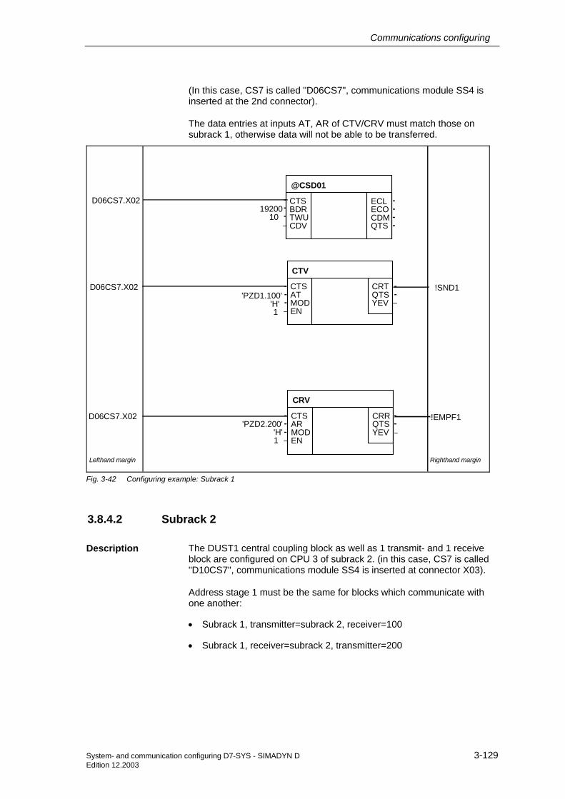
Communications configuring
System- and communication configuring D7-SYS - SIMADYN D 3-129 Edition 12.2003
(In this case, CS7 is called "D06CS7", communications module SS4 is inserted at the 2nd connector).
The data entries at inputs AT, AR of CTV/CRV must match those on subrack 1, otherwise data will not be able to be transferred.
Righthand marginLefthand margin
ECLECOCDMQTS
----
---
CTSBDRTWUCDV
@CSD01
CRTQTSYEV
CTV
--
---
CTSATMODEN
D06CS7.X02'PZD1.100'
'H'1
CRRQTSYEV
CRV
--
---
CTSARMODEN
!EMPF1'PZD2.200'
'H'1
1920010
D06CS7.X02
!SND1
D06CS7.X02
Fig. 3-42 Configuring example: Subrack 1
3.8.4.2 Subrack 2
The DUST1 central coupling block as well as 1 transmit- and 1 receive block are configured on CPU 3 of subrack 2. (in this case, CS7 is called "D10CS7", communications module SS4 is inserted at connector X03).
Address stage 1 must be the same for blocks which communicate with one another:
• Subrack 1, transmitter=subrack 2, receiver=100
• Subrack 1, receiver=subrack 2, transmitter=200
Description

Communications configuring
3-130 System- and communication configuring D7-SYS - SIMADYN D Edition 12.2003
Righthand marginLefthand margin
ECLECOCDMQTS
----
---
CTSBDRTWUCDV
@CSD01
CRTQTSYEV
CTV
--
---
CTSATMODEN
D10CS7.X03'PZD2.200'
'H'1
CRRQTSYEV
CRV
--
---
CTSARMODEN
!EMPF2'PZD1.100'
'H'1
1920010
D10CS7.X03
!SND2
D10CS7.X03
Fig. 3-43 Configuring example: Subrack 2

Communications configuring
System- and communication configuring D7-SYS - SIMADYN D 3-131 Edition 12.2003
3.9 DUST2 coupling
To output messages from a message system, printers can only be connected to SIMADYN D which can handle the serial communications protocol X-ON/X-OFF with additional telegram block check characters (ETX/ACK).
3.9.1 Hardware structure
The following hardware is required for the DUST2 coupling:
• CS7 communications module with SS4 communications module
The SC56 cable can be used to connect a printer to the communications module CS7 with communications module SS4 if an appropriate adapter is used. This adapter converts a 25-pin high-density connector into a 25-pin sub-D socket connector.
The printer must be equipped with the matching interface module, which is parameterized for the settings configured with SIMADYN D (e. g. baud rate, parity).
Further information on the printer, refer to the printer Manual.
• Printer DR 215-N is used as message printer. (Refer to Catalog IC40 from AUT and SIMADYN D Info 94/14)
3.9.2 Configuring
As the DUST2 protocol operates according to the "point-to-point" principle, and a message printer can only be handled as communications partner, to output messages, a transmit address is not required (when using CS7/SS4, only a channel name should be specified at the corresponding output block; address stages 1 and 2 are not used).
A central coupling block is available to configure the DUST2 coupling and to set the format for printer output:
• @CSD02: For a coupling via CS7/SS4
The DUST2 central coupling block is used to initialize the communications interface (hardware driver and DUST2 software). In addition, it can configure the protocol (minimum) with the following I/O (connections):
• PAR (parity) This specifies the parity in the telegram characters (0 = even, or 1 = odd number of ones)
Application
Hardware required
Cables
Printer
DUST2 addresses
Central coupling block

Communications configuring
3-132 System- and communication configuring D7-SYS - SIMADYN D Edition 12.2003
• FRM (format selection) To optically improve the text, it can either be output in a standard format (FRM = 0) (lefthand and righthand margin, narrow fonts, page break) or non-formatted (FRM = 1). The format instruction is only used by DUST 2 in conjunction with the 20mA interface after the interruption has been identified.
− SIMADYN D is powered-up (20 mA current source from SIMADYN D as transmitter is active).
− The printer is powered-down (20mA current source from the printer is inactive as transmitter).
− The 20 mA connecting cable from SIMADYN D to the printer is not inserted.
The MSIPRI message output block should be used (refer to Chapter Communications utility, message system).
Text output block

Communications configuring
System- and communication configuring D7-SYS - SIMADYN D 3-133 Edition 12.2003
3.10 DUST3 coupling
The DUST3 data transfer protocol is mainly used to exchange data with SIMATIC S5 or TELEPERM M.
From the SIMATIC S5/TELEPERM M perspective, SIMADYN D behaves just like a SIMATIC S5/TELEPERM M device, with the restriction, that telegram fetch is not possible (however test telegrams from TELEPERM M are responded to).
The data transfer protocol is a 3964(R) protocol with an RK512 computer coupling protocol overlay (a precise description, e. g. for: SIMATIC S5 COM525).
The data transfer time is 1.15 ms/byte at 9600 baud. The telegram frame including response telegram is 25 bytes long (net data length =< 128 bytes).
• Example: At 9600 baud, it takes: 1.15 ∗ (25 + 50) = 86 ms, to transfer 50 bytes of net data
The maximum telegram length is 750 bytes. However, there are coupling partners (e. g. TELEPERM), which permit a maximum telegram length of only 128 bytes.
3.10.1 Hardware structure
The following hardware is required for the DUST3 coupling:
• CS7 communications module with an SS4 communications module
3.10.2 Configuring
3.10.2.1 Data entries at inputs AT, AR
A channel name and address stage 1 must be specified at input AT/AR. Data entries for address stage 2 are optional. For address stage 1 and address stage 2 there is a defined syntax, which is now described:
Address stage 1 consists of:
• SIMATIC processor number: Precisely one character, value range "1".."4". This entry is optional and is only practical for transmitters. The data entry is used to address a SIMATIC processor, as long as the receiving SIMATIC can handle the multi-processor technology used.
• Output command with data block and data word: "ADxxx-yyy"
− AD: "Output" "data block"
− xxx: Data block, value range 1..255
Application
Data transfer protocol
Data transfer time
Telegram length
Hardware required
Rules

Communications configuring
3-134 System- and communication configuring D7-SYS - SIMADYN D Edition 12.2003
− - : Hyphen as separating character
− yyy: Data word, value range 0..256
• Or an output command with absolute SIMATIC address: "ASwwwww"
− AS: "Output" "memory"
− wwwww: Absolute address, value range 0..65535
In the transmit direction, the output command addresses the data blocks and memory addresses in the SIMATIC. In the receive direction, the data entry is used to emulate an appropriate data block or memory address, so that an output command, received by a SIMATIC, is correctly processed.
NOTE SIMADYN D does not support a "Fetch" telegram or input command ("E" code).
The optional address stage 2 consists of:
• Coordination flag: This is only practical for transmitters: "zzz-u"
− zzz: Coordination flag byte, value range 1..255
− - : Hyphen as separator
− u: Coordination flag bit, value range 0..7
• AT- 'PZD1.3AD20-10.130-5"'
− The data are sent to SIMATIC processor No. 3 and saved in data block 20, from data word 10. A coordination flag must be specified
• AT- 'PZD2.AD10-30'
− The data are sent to the SIMATIC and are saved in data block 10 from data word 30.
• AR- 'PZD3.AD50-50'
− Data are received from a SIMATIC, which transmits output command "AD50-50" to SIMADYN D.
3.10.2.2 Central coupling block
Central block @CSD03 is required to configure the DUST3 coupling via an SS4 communications module in a communications module CS7. This block has the task to initialize and parameterize the data interface on a communications module SS4 in a communications module CS7. All CPUs can access the CS7 communications module.
The central coupling block has the following I/O (connections) to parameterize DUST3:
Example of data entries at inputs AT, AR
General
I/O (connections)

Communications configuring
System- and communication configuring D7-SYS - SIMADYN D 3-135 Edition 12.2003
• PRI (transmit priority) If a transmit request occurs simultaneously, this defines which of the two communication partners can first transmit. PRI=0 means that the partner can first transmit; PRI=1 means that the SIMADYN D first transmits. This data entry must be different for SIMADYN D and the communications partner.
• BCC (block check character) This defines whether a block check character is also transferred. BCC=0 means that no block check character is sent (this corresponds to procedure 3964, Hamming distance=2); BCC=1 means that a block check character is sent (corresponds to procedure 3964R, Hamming distance=4). For SIMADYN D and the coupling partner, this data entry must be the same.
• LS (transport layer identification) This defines whether and how the RK512 protocol is to be used.
− LS=0: The RK512 protocol is used, as specified for SIMATIC; especially for data transfers in the single-word format, the data words high byte before low byte are transferred ("Big-Endian" or "Motorola" format).
− LS=1: Protocol RK512 is used, but for single-word format data transfer, the data words are transferred, low byte before high byte ("Little-Endian" or "Intel" format). For example, this is used for couplings to COROS.
− LS=2: Protocol RK512 is not used. Data is directly transferred with the procedure 3964(R).
3.10.2.3 Transmit/receive blocks
All transmit- and receive blocks of the process data utility can be used which have address inputs (AT/AR). To start off with, a unique channel name must be specified at these connections. This is then followed, separated by a point (period - separator), by the address data required for DUST3.
General information and connections (I/O)

Communications configuring
3-136 System- and communication configuring D7-SYS - SIMADYN D Edition 12.2003
3.11 DUST7 coupling
3.11.1 General
The DUST7 coupling is a basic, serial point-to-point connection. The communication utilities, process data and message system, can use the DUST7 coupling.
The main use of the DUST7 coupling is:
• to transfer process data to devices with basic serial interfaces or PCs with the customers own applications, or
• to output messages on simple terminals.
In addition to the pure net data, an optional configurable end of telegram with maximum 2 characters is transferred. If an end of telegram has not been configured, then the end of telegram is identified by an interval time of 4 character times.
3.11.2 Hardware
The following hardware is required for the DUST7 coupling:
• Subrack
• CPU
• CS7 module with SS4 communications module (this must also be configured in HWConfig)
An RS232 interface is used which can also be changed over to 20 mA or RS485 by inserting an SS2 or SS3 interface module.
3.11.3 Configuring
The @CSD07 central coupling block must be configured. The character frame and the end of telegram can be configured at its initialization inputs.
Further information on the @CSD07 central block, refer to the User Documentation "SIMADYN D, function block library".
A maximum of one transmit block and one receive block (CTV and CRV) may be configured. Only a channel name must be specified as address parameter (AT-, AR input). The channel name must be different for the transmitter and receiver.
One or several message output blocks (MSIPRI) can be configured. If several message output blocks are configured, then their channel names must be identical ("Select" data transfer mode).
Using the DUST7 coupling
Hardware required
Central DUST7 coupling block
Process data, transmitter and receiver
Message output block

Communications configuring
System- and communication configuring D7-SYS - SIMADYN D 3-137 Edition 12.2003
3.12 MPI coupling
3.12.1 Characteristics and hardware
MPI (Multi Point Interface) is the standard communications protocol for SIMATIC S7/M7. Data transfer is realized via a multi-master bus with a maximum of 126 nodes.
For SIMADYN D, MPI is used to connect the CFC for start-up and testing configured software, and is also used to communicate with WinCC and SIMATIC OPs.
With the MPI coupling, the communication utilities service (FB-SER) and S7 communications (FB-S7OS) are used.
The following hardware is required for the MPI coupling:
• Subrack
• CPU
• CS7 module with SS52 communications module (this must also be configured in HWConfig)
3.12.2 Configuring
The CS7 communications module and the SS52/MPI communications module must be configured in HWConfig. Its own MPI address must be specified for SS52/MPI.
Precisely one @CSMPI central coupling block must be configured for each SS52/MPI. The @CSMPI function block initializes and monitors the MPI coupling.
Additional information to configure an MPI coupling, refer to:
• Section "Communications Utility Service"
• Section "Communications with SIMATIC Operator Panels"
• Section "Communications with WinCC (MPI)"
Characteristics
Hardware
HWConfig
Function block @CSMPI

Communications configuring
3-138 System- and communication configuring D7-SYS - SIMADYN D Edition 12.2003
3.13 USS master coupling
The USS master coupling defines an access technique, according to the master-slave principle for data communications via a serial bus.
• A multi-point-capable coupling is supported
• Master-slave access technique
• Single-master system
• 1 master and a maximum of 31 slaves
• Bus line: Line without any branching
The master addresses the individual slaves using an address character in the telegram. A slave can never initiate data transmit. Individual slaves cannot transfer data directly between themselves.
The following SIMADYN D communications utilities can be connected to the USS master coupling:
• Process data
• Message system
• Display control
• Parameter processing
3.13.1 Hardware structure
The following hardware is required for the USS master coupling:
• CS7 communications module with an SS4 communications module (USS master). The interface is an RS485 interface (SS31 interface sub-module).
The bus cable must be terminated at both ends. A 150 Ω resistor is connected between the RS485P and RS485N data signal lines at the first and last nodes.
If a node is not transmitting, then the bus has an undefined potential, because all transmitters are switched into the high-ohmic state. To suppress signal faults in this status, a basis network is connected to the bus so that it has a defined positive signal level. The basis network should be connected at the nodes where the bus cable ends.
General
Features
Mode of operation
SIMADYN D communication utilities
Hardware required
Bus termination
Basic network

Communications configuring
System- and communication configuring D7-SYS - SIMADYN D 3-139 Edition 12.2003
390 Ω
390 Ω
150 Ω
RS485+
RS485-
Bus terminating resistor
+5V
0V
Resistor to thesupply voltage
Resistor to thesignal reference
Fig. 3-44 Basis network and bus termination
390 Ω
390 Ω
150 Ω
390 Ω
390 Ω
150 Ω
Housing ground,grounding barThe screen should beconnected to the grounding barthrough the largest possiblesurface area where thecable enters the cabinet
Screen
Data line
Potential bonding
Housing ground,grounding bar
The screen should beconnected to the grounding barthrough the largest possiblesurface area where the cableenters the cabinet.
Fig. 3-45 Screening and potential bonding
This circuit should be used if the SS4 communications module is used as end node on the USS bus, i. e. at the end of the bus cable.
Connector assignment with basis network

Communications configuring
3-140 System- and communication configuring D7-SYS - SIMADYN D Edition 12.2003
390 Ω
150 Ω
RS485+
22
390 Ω
RS485-.
18
21
17
5
8
7
14
2
20
USS busSS4
Fig. 3-46 Connector assignment with basis network
This circuit should be used if the SS4 communications module is not used as end node on the USS bus, i. e. not at the end of the bus cable. In this case, the bus cable is looped-through the bus connector.
RS485+
RS485-
21
17
5
8
7
14
2
20
USS busSS4
Fig. 3-47 Connector assignment without basis network
Connector assignment without basis network

Communications configuring
System- and communication configuring D7-SYS - SIMADYN D 3-141 Edition 12.2003
3.13.2 Data transfer technique
Data transfer is realized in the half-duplex mode via an RS485 interface (2-conductor cable). The master addresses all of the slaves, one after another, with a telegram. The addressed slaves transmit a telegram back to the master. In accordance with the master-slave procedure, when the slave receives a telegram, it must first transmit a telegram back to the master before the master re-addresses this slave.
The sequence of the addressed slaves can be specified by entering the station address in a circulating list (refer to the central coupling block @CSU). If several slaves must be addressed in a faster cycle (scan) than the others, then their station address can be configured a multiple number of times in the circulating list.
The scan time isn’t defined due to the inconsistent telegram delay- and processing times.
0 0 1 1 0 0
t0 t1 t2 t3 t4t5
t6
Cycle time
t0: Telegram delay time, master-slave0t1: Response delay time, slave0t2: Telegram delay time, slave0-mastert3: Processing time, mastert4: Telegram delay time master-slave1t5: Response delay time, slave1t6: Telegram delay time slave1-master
...
Fig. 3-48 Definition of the cycle time
3.13.3 Transferred net data
On the receive- as well as on the transmit side, up to 252 bytes of net data can be transferred. The net data length can be configured and is dependent on the particular application.
3.13.4 Configuring
3.13.4.1 Central coupling block @CSU
An @CSU central coupling block has to be configured to initialize and monitor the coupling. The central block only initializes the coupling during cyclic operation; the coupling remains inhibited before cyclic operation.
Mode of operation
General
Initialization and monitoring

Communications configuring
3-142 System- and communication configuring D7-SYS - SIMADYN D Edition 12.2003
Thus, it can take several sampling periods until the first telegram is transmitted or received!
3.13.4.2 Function blocks which can be used
All of the function blocks for the communications utilities, process data, message system and display, can be used.
A unique channel name must be specified at inputs AT/AR. Address stage 1 and address stage 2 are used as follows:
AT/AR: "Channel name.address stage 1.address stage 2"
• Channel name
− unique channel name
• Enter "." after the channel name
• Address stage 1
− telegram type
− value range and significance: 0: drive telegram 1: OP2 telegram
• Enter "." after address stage 1
• Address stage 2
− station address of the slaves where data is to be transferred.
− value range and significance: 0 - 30: slave station address 99: broadcast address
1. AT- 'SENDER.0.25' − the channel with the name BROADCAS sends a device telegram
to the station with number 25.
2. AT- 'BROADCAS.1.99' − the channel with the name BROADCAS transmits an OP2 telegram
as broadcast telegram.
NOTE • Precisely one transmit- and precisely one receive channel are permitted for each slave. If more transmitters/receivers attempt to log-on, then these channels remain active.
• A maximum of 16 broadcast transmitters are permitted. If more than one broadcast transmitter attempts to log-on, these channels do not go into operation.
General
Data entries at inputs AT, AR
Examples of data entries at AT, AR

Communications configuring
System- and communication configuring D7-SYS - SIMADYN D 3-143 Edition 12.2003
3.13.4.3 Telegram types
The "Drive" telegram type should be used for communications to variable-speed drives. Drive telegrams are exclusively transmitted as standard telegrams in accordance with the drive profile (refer to /1/).
The "OP2" telegram type should be used for establishing communications to operator control devices. OP2 telegrams are exclusively transmitted as special telegrams (refer to /1/).
Station address "99" should be configured for communications using broadcast telegram. Broadcast telegrams are only transmitted as special telegrams (refer to /1/). Broadcast telegrams cannot be transmitted to drives ("drive" telegram type)!
The master can request a mirror telegram from a slave. To realize this, the master transmits a telegram to the slave. This telegram differs from the standard telegram only by the fact that one bit of the address byte is set. The slave transmits this telegram unchanged back to the master (mirrored). This mirror telegram can be used to check data transfer between master and slave. Mirror telegrams are transmitted, dependent on the configured telegram type, either as standard telegram in accordance with the device profile ("drive" telegram type) or as special telegram ("OP2" telegram type) (refer to /1/).
3.13.5 Mode of operation
The USS master coupling cyclically transmits data, whereby all of the slave nodes are addressed one after the other. In this case, it is unimportant whether new transmit data were made available by the blocks or not. If no new data was made available, then the data which were last transmitted, are again transferred.
The USS master coupling only identifies a valid receive telegram, if the number of received net data is the same as the configured number of receive data.
The sequence of the slaves which are addressed can be specified by appropriately entering the station address in a circulating list (also refer to the central coupling block @CSU). If several slaves are to be addressed in a faster cycle than others, then their station address can be configured a multiple number of times in the circulating list.
If a circulating list is not configured, all of the slaves are addressed according to their station address in an increasing sequence.
In the broadcast mode (station address=99), the master transmits a telegram to all of the slaves connected to the bus. The slaves do not respond to a broadcast telegram. The broadcast telegram is processed at the end of each bus circulation (all slaves are addressed once). In this case, a maximum of two broadcast telegrams are transmitted. If the maximum of 16 possible broadcast tasks are available, these are transmitted after 8 bus cycle. The USS master coupling ensures that a
Drive telegram
OP2 telegrams
Broadcast telegrams
Mirror telegrams
Transmit
Receiving
Circulating list
Broadcast

Communications configuring
3-144 System- and communication configuring D7-SYS - SIMADYN D Edition 12.2003
"slower broadcast transmitter" is not blocked by a "faster" broadcast transmitter.
The USS master coupling monitors the delay time of the received telegram. The time interval between the last character of the transmitted telegram and the first character of the received telegram is considered to be the delay time. The maximum permissible delay time is 20 ms. If the addressed slave does not respond within the maximum permissible delay time, the USS master coupling flags the receive channel, assigned to this slave, as being faulted. If a receive channel is not configured, no error entry is made.
The USS master coupling then transmits a telegram destined for the next slave.
The error entry for the faulted slave is only reset after the slave receives the next error-free telegram.
3.13.6 USS master on the T400 technology module
This section describes the special issues which you have to observe when using the USS master coupling on the T400 technology module.
In this section, you will only find the differences over to Section 13.1 to 13.5.
The USS master coupling allows you to connect, approx.
− 17 drive converters or
− 19 OP2 operator control devices, or
− 8 drive converters and 8 OP2
As prerequisite for the coupling, you will require a T400 technology module (terminals 70..71, serial interface X01 or terminals 74..75, serial interface X02).
Data transfer uses a half-duplex technique according to the RS485 Standard via a 2-conductor cable.
• It is not possible to simultaneously use two USS couplings (USS master, USS slave) on the serial X01 and X02 interface.
• You must set switch S1/8 to the on position so that you can use the serial X01 interface for the USS master coupling.
3.13.6.1 Basis network for the T400 technology module
You must set the switch according to the table below dependent on whether you are using the T400 technology module as end node or not as end node on the USS bus, i.e. at the end or not at the end of the bus cable.
Monitoring mechanisms and error response
Please note:

Communications configuring
System- and communication configuring D7-SYS - SIMADYN D 3-145 Edition 12.2003
Serial interface Switch
X01 S1/1 and S1/2
X02 S1/3 and S1/4
3.13.6.2 Initialization
You must configure the @USS_M function block so that you can initialize the USS master coupling.
3.13.6.3 Broadcast
You may configure precisely 2 broadcast senders. If you configure more than 2 broadcast senders, then these will not go into operation.
If the maximum of 2 possible broadcast tasks are present, then these are sent precisely after one bus circulating time.
3.13.7 Literature
/1/ Specification "Universal serial interface protocol (USS protocol) Order No.: E20125-D0001-S302-A1 Version: 09.94 Bohrer/Möller-Nehring ASI 1 D SP3
/2/ EMC Guidelines refer to the User Documentation SIMADYN D, hardware

Communications configuring
3-146 System- and communication configuring D7-SYS - SIMADYN D Edition 12.2003
3.14 USS slave coupling
The USS slave coupling allows you to
− transfer process data
− handle and visualize parameters
To exchange process data, you have a maximum of
− one transmit channel (actual values) and
− one receive channel (setpoint).
You can transfer up to 32 process data sets, each 16 bits via each of these channels.
For the coupling, you require a T400 technology board (terminals 70..71, serial interface X01 or terminals 74..75, serial interface X02).
Data transfer is realized using a half-duplex technique via a two-conductor cable in accordance with the RS485 Standard.
• It is not possible to simultaneously use two USS couplings (USS master, USS slave) at serial interfaces X01 and X02.
• You must switch-in switch S1/8 (close) so that you can use serial interface X01 for the USS slave coupling.
3.14.1 Basis network for the T400 technology module
Depending on whether you use the T400 technology board as end node or not as end node on the USS bus , i.e. at the end or not at the end of the bus cable, then you must open or close the switches according to the table below.
Serial interface Switches
X01 S1/1 and S1/2
X02 S1/3 and S1/4
3.14.2 Initialization
You must configure the function block @USS_S so that you can initialize the USS slave bus coupling .
Please note the following:

Communications configuring
System- and communication configuring D7-SYS - SIMADYN D 3-147 Edition 12.2003
3.14.3 Exchanging process data
3.14.3.1 Transmitting
You must configure the CTV function block so that you can transmit process data. Bus
Select the "Refresh" mode as the data transfer mode, i.e. always the most up to date data are available to you at the receive side.
At connection AT, configure a unique channel name for this data interface.
• If you have configured, using virtual connections, more data than specified at connection PZD of function block @USS_S, then this excess data is cut-off.
• If you have configured, using virtual connections, less data , than are specified at the PZD connection of function block @USS_S, then the telegram is filled-up with "0s".
• The transmit telegram is started asynchronously to the sampling time of the CTV function block after a telegram has been received.
Please refer to the "Manual, configuring the communications D7-SYS, Chapter communications utility, process data" for additional configuring rules when transferring process data.
3.14.3.2 Receiving
In order that you can receive process data, you must configure the CRV function block. Bus
Select the "Refresh" mode as the data transfer mode, i.e. always the most up to date are available to you at the receive side.
At connection AR, configure a unique channel name for this data interface.
• If you have configured, using virtual connections, more data than specified at connection PZD of function block @USS_S, then this excess data is cut-off.
• If you have configured, using virtual connections, less data , than are specified at the PZD connection of function block @USS_S, then the telegram is filled-up with "0s".
• The transmit telegram is received asynchronously to the sampling time of the CRV function block, i.e. the sampling time of function block CRV is the max. deadtime between receiving and processing data.
Please observe:
Please note:

Communications configuring
3-148 System- and communication configuring D7-SYS - SIMADYN D Edition 12.2003
Please refer to the "Manual, configuring the communications D7-SYS, Chapter communications utility, process data" for additional configuring rules when transferring process data.
3.14.4 Handling and visualizing parameters
You must configure the @DRIVE function block so that you can handle & visualize parameters.
Please refer to the "Manual, configuring communications D7-SYS, Chapter "Parameterizing SIMADYN D" for additional configuring rules for handling & visualizing parameters.
3.14.5 Special features for 4-conductor operation of the USS-slave coupling
Thee USS slave coupling via serial interface X02 allows you to communicate with a standard COM interface (V24/RS232) of a PC using 4-conductor operation.
In order that you can use this capability, you must
− set connection WI4 to "1" at function block @USS_S
− connect the COM interface of your PC using an interface converter (V24 <--> RS485) at terminals 72..75 (serial interface X02)
− close or open switches S1/5 and S1/6 (refer to Chapter 14.1)
3.14.6 USS-slave coupling via V24/RS232
The USS-slave coupling allows you to communicate with a standard COM interface (V24/RS232) of a PC via serial interface X01.
In order that you use this capability, you must
− set connection WI4 to "1" at function block @USS_S
− connect the COM interface of your PC to terminals 70..71 (serial interface X01)

Communications configuring
System- and communication configuring D7-SYS - SIMADYN D 3-149 Edition 12.2003
3.15 Peer-to-peer coupling
The peer-to-peer coupling is a serial coupling from drive converter to drive converter. It allows you, for example
− to implement a fast digital setpoint cascade
− to power-up a multi-motor drive group together
To transfer process data, you can use, a maximum of
− one transmit channel (setpoints)
− one receive channel (actual values)
You can transfer up to five 16-bit pieces of process data via each of these channels.
You can configure the net data length on the transmit- and receive side differently.
To be able to use the coupling, you require a T400 technology module (terminals 72..75, serial interface X02).
Data transfer is realized using a full-duplex technique with a four-wire cable according to the RS485 standard.
3.15.1 Initialization
You must configure the @PEER function block so that can initialize the peer-to-peer coupling.
3.15.2 Transferring process data
3.15.2.1 Transmitting
You must configure the CTV function block so that you can transmit process data.
Select the "Handshake" mode as the data transfer mode, i.e. the telegram in the previous sampling time must have been completely sent before a new telegram can be sent.
For this reason, adapt the sampling time of the CTV function block
− to the baud rate, and
− the number of process data
according to the telegram run time table, provided below.
At connection AT, configure unique channel names for this data interface.

Communications configuring
3-150 System- and communication configuring D7-SYS - SIMADYN D Edition 12.2003
• If you have configured, using virtual connections, more data than specified at connection LTT of function block @PEER, then this excess data is cut-off.
• If you have configured, using virtual connections, less data , than are specified at the LTT connection of function block @PEER, then the telegram is filled-up with "0s".
• The transmit telegram is started synchronously to the sampling time of the CTV function block, i.e. there is no dead time.
Please refer to the "Manual, configuring the communications D7-SYS, Chapter communications utility, process data" for additional configuring rules for exchanging process data.
Number of process data, each 16 bit
Baud rate [kbaud]
9.6 19,2 38,4 93,75 187,5
1 5.7 2.9 1.43 0.6 0.3
2 8.0 4.0 2.0 0.8 0.4
5 16 8.0 4.0 1.6 0.8
Table 3-58 Telegram run times [ms] as a function of the baud rate and the number of process data
3.15.2.2 Receiving
You must configure the CRV function block so that you can receive process data.
Select the "refresh" data transfer mode, i.e. you always have access to the most up to date data.
Configure a unique channel name for this interface at connection AR.
• If you have configured, using virtual connections, more data than specified at connection LTR of function block @PEER, then this excess data is cut-off.
• If you have configured, using virtual connections, less data , than are specified at the LTR connection of function block @PEER, then the telegram is filled-up with "0s".
• The transmit telegram is started asynchronously to the sampling time of the CRV function block after a telegram has been received, i.e. the sampling time of function block CRV is the max. deadtime between receiving and processing data.
Please refer to the "Manual, configuring the communications D7-SYS, Chapter communications utility, process data" for additional configuring rules when transferring process data.
Please observe:
Please observe:

Communications configuring
System- and communication configuring D7-SYS - SIMADYN D 3-151 Edition 12.2003
3.16 SIMATIC P-bus coupling
The FM 458 has a RAM memory (128 Kbytes) which can be used to connect it to a P bus. Data can be exchanged with one SIMATIC S7-CPU via this P-bus memory. The FM 458 is passive on the P bus, i.e. the FM 458 cannot directly access other modules of the SIMATIC station. There are 3 ways to transfer data to the SIMATIC CPU:
• 4 bytes can be received from the SIMATIC-CPU using a process interrupt
• 128 bytes can be sent and received via SIMATIC I/O accesses
• extremely large data quantities can be sent and received using data blocks/sets
The EXM 438, EXM 448 expansion modules can only be accessed from the FM 458 (via the FM-internal LE bus); they have no direct connection to the P bus.
The start addresses of the I/O, under which a SIMATIC CPU can address the I/O range of the FM 458, are configured in HW Config. The addresses for inputs and outputs can differ.
HW Config menu: “Edit/Properties/Addresses” Default: 512 (decimal; for inputs and outputs)
The FM 458 also sends diagnostic interrupts to the SIMATIC-CPU, independent of what has been configured, in the following situations.
• Transition into the statuses
− “initialization error “
− “system error “
− “user stop “
− “RUN“
• If the memory module is inserted or withdrawn, or is not available
P-bus memory
Accessing EXM 438, EXM 448
Addresses
Diagnostic interrupts

Communications configuring
3-152 System- and communication configuring D7-SYS - SIMADYN D Edition 12.2003
3.16.1 Overview of the 3 data transfer types, FM 458 ←→ SIMATIC-CPU
Designation Number of data Configuring Speed Computation time (on the FM 458)
1. Process interrupt
4 bytes to SIMATIC-CPU
FM 458: Block PAS7 SIMATIC-CPU: OB40, etc.
When PAS7 is called, an interrupt is initiated on the SIMATIC CPU, e.g. OB40 (if a higher priority interrupt isn't being processed at precisely that time).
Extremely low: only for PAS7
2. Data transfer with I/O (peripheral) accesses
128 bytes in the send and 128 bytes in the receive direction
FM 458: blocks S7RD, S7WR SIMATIC-CPU: transfer commands for the I/O (periphery)
When a block is called, data is immediately read-out of the memory or written into the memory.
Computation times of all configured S7RD/S7WR blocks: each approx. 5µs.
3. Transferring data sets/blocks
For extremely high quantities of data: max. approx. 125 data sets with each max. 240 bytes (refer below.)
FM 458: “virtual connections” with blocks @CPB, CRV/CTV SIMATIC-CPU: system functions SFC58/59 Consistency: All of the data associated with a telegram are consistent with one another, i.e. they are transferred in a "data package".
The data associated with a telegram are read or sent when the block is called.
Computation time is required for each data set via telegram processing (approx. 30µs each CRV/CTV) and to copy the net data into/out of the P-bus memory. If extremely large data quantities are involved and there is a P-bus utilization, then a somewhat higher degree of computation time can be assumed. The data are transferred into the memory in blocks up to max. 16 bytes. The P bus must be re-assigned between the blocks, which means that the required computation time may increase.
Table 3-59 Data transfer, SIMATIC-CPU ↔ FM 458
All of the 3 data transfer types can be used in parallel.

Communications configuring
System- and communication configuring D7-SYS - SIMADYN D 3-153 Edition 12.2003
3.16.2 Initiating a process interrupt on SIMATIC-CPU
Function block PAS7 initiates, when triggered, a process interrupt to the assigned S7-CPU. Supplementary interrupt info of 4 bytes is configured at the IFO input, which contains net data information.
When an interrupt is initiated, the interrupt OB, which should be configured in HW Config, is called in the SIMATIC S7-CPU. The supplementary interrupt info, taking up 4 bytes, is written into the local data of the interrupt OBs.
The start address of the input/outputs of the sending FM 458 (to be configured in HW Config; in the example 512dec = 200hex) is also saved in the local data of the OB 40.
SIMATIC S7-CPU(SL program)
FM 458 (CFC program)P busmemory
of the FM 458
W#16#200
Info memoryfor process
interrupt(4 Bytes)
OB40"Hardware interrupt"
//Load alarm source//(which module?):
L #OB40_MDL_ADDR T MW20
//Load alarm info: L #OB40_POINT_ADDR T MW22
0:1:2:3:
DW IFOBO I
PAS716#ABCD1234
Trigger (0/1)DW#16#ABCD1234
512dec = 200hex
2.Select number of the OB(e.g. 40)as well as possibly the.peripheral address(es)(Default: 512)
1.Select interrupt source:"Process"(or "Hardware")
via "Edit/Properties" menu
HW Config
Fig. 3-49 Data transfer to the S7-CPU with process interrupt
PAS7

Communications configuring
3-154 System- and communication configuring D7-SYS - SIMADYN D Edition 12.2003
3.16.3 Data transfer via I/O accesses
To transfer low data quantities: up to max. 128 bytes
Appropriate function blocks are available for each data transfer direction and for each data type to be transferred.
SIMATIC-CPU FM 458
Data type Transfer command (SL program)
Write direction
CFC function block
Data type
BYTE T PAB abs.addr. S7RD_B BOOL
INT T PAW abs.addr. S7RD_I INT
DINT T PAD abs.addr. S7RD_D DINT
REAL T PAD abs.addr. S7RD REAL
BYTE L PEB abs.addr. S7WR_B BOOL
INT L PEW abs.addr. S7WR_I INT
DINT L PED abs.addr. S7WR_D DINT
REAL L PED abs.addr. S7WR REAL
Table 3-60 Data types and the associated commands/blocks for peripheral accesses
The 8-bit CFC data type “BOOL“ is represented in the SIMATIC S7-CPU as “BYTE“ data type. This means that the SIMATIC S7 user must appropriately set or evaluate the decisive MSB (Most Significant Bit):
• S7-CPU: bit variable
• FM 458: 1XXX XXXX = TRUE 0XXX XXXX = FALSE
In order to achieve high processing speeds with 32-bit accesses, the following must be ensured by appropriately configuring the FM 458/CFC (offset, refer below) as well as programming the SIMATIC-CPU, so that
• 16-bit values (INT/WORD data types) are saved at even addresses (word limits) and
• 32-bit values (REAL, DINT data types) at addresses which are divisible by 4 (double word limits)
are saved in the two P-bus memories which are 128 bytes large.
The FM 458 side is accessed using the S7RD/S7WR blocks, at which the offset of the data to be transferred is configured, i.e. the position within the 128 bytes.
Application
Blocks and transfer commands
CFC data type “BOOL“
Data save
Entering the offset for FM 458

Communications configuring
System- and communication configuring D7-SYS - SIMADYN D 3-155 Edition 12.2003
When assigning the offset, the number of all of the values located before the block involved (blocks) and their data type (assigned memory range in bytes) are taken into account. It is especially important that possible overlaps are avoided. Gaps between individual values are not permitted (e.g. for reserve ranges).
However, the offset is not specified in the number of bytes, but as a multiple of the data type of the associated function block!
In this case, the offset, starting from an entry in bytes must be divided by 2 (for INT types) or by 4 (for REAL/DINT types) and this result must be configured at the offset input.
Using this technique, it is automatically guaranteed, that the data to be transferred is available at optimum addresses, i.e. addresses which can be quickly accessed. However, if the data is unfavorably structured, this can result in memory cells which cannot be used (refer to the example diagram below). In order to avoid this, for example, BYTE- and INT types should be individually distributed over the memory area, but should be arranged one after the other (consecutively).
Absolute addresses are used in the SIMATIC S7 program which are obtained from the FM 458 address and the offset of the associated S7RD/S7WR block in bytes (!):
Absolute address = (offset x F) + FM 458 I/O address
FM 458 I/O address: The start address, configured in HW Config for the I/O range of the associated FM 458
Offset = Value at the associated S7RD/S7WR function block F = Data type length in number of bytes:
F = 1 for S7WR_B, S7RD_B F = 2 for S7WR_I, S7RD_I F = 4 for S7WR, S7RD, S7WR_D, S7RD_D
Absolute address for SIMATIC-CPU

Communications configuring
3-156 System- and communication configuring D7-SYS - SIMADYN D Edition 12.2003
SIMATIC S7-CPU(SL program)
FM 458 (CFC program)
HW Config
P-busmemory
of the FM 458
L 1.234568e+038 T PAD 512
L 2.000000e+000 T PAD 516
L 1234 T PAW 520
L 12345678 T PAD 524
L B#16#80 T PAB 528
L 5678 T PAW 530
OFF Y RS7RD
2.01
0 OFF Y RS7RD
1.234568e+38
3 OFF Y DI
S7RD_D
OFF Y IS7RD_I
12344
OFF Q BO
S7RD_B16
OFF Y IS7RD_I
9
1
1.23e+38 R X1 OFF
S7WR
BO I0 OFF
S7WR_B
I X4 OFF
S7WR_I
DI X3 OFF
S7WR_D
3456
16#12345678
L PEB 512T MB 20
L PED 516T MD 22
L PEW 520T MW 26
L PED 524T MD 28
not used!
not used! 1
5678
not used!
not used!
B#16#FF
1.23 e+038
3456
DW#16#12345678
Send function blocks (write)Send memory(128 bytes)
0:1:2:3:4:5:6:7:8:9:10:11:12:13:14:15:16:17:
127:........
Receive
Receive function blocks (read)Receivememory(128 bytes)
Send
0:1:2:3:4:5:6:7:8:9:10:11:12:13:14:15:16:17:18:19:20:
127:........
16#12345678
Fig. 3-50 Data transfer with peripheral accesses (I/O accesses)
3.16.4 Transferring data sets
If extremely large quantities of data are to be transferred, e.g. for visualization applications (WinCC), or if data have to be transferred between SIMATIC and FM 458 for an extremely high number of drives.
• Memory available on the P bus: 114688 bytes (0x1C000 hex), for various "data sets" (or "telegrams").
• max. 125 read and 125 write data sets
• max. length per data set (telegram): 240 bytes
Application
Features, limit values

Communications configuring
System- and communication configuring D7-SYS - SIMADYN D 3-157 Edition 12.2003
• max. data quantity which can be transferred: For internal data management and buffer mechanisms, the following are required - for received data sets, 2x data set length - for sent data sets 3x data set length The sum of the required bytes for all of the write and read data sets may not exceed the above mentioned memory size of 114688 bytes!
Example: Max. number of write and read data sets, each 240 bytes: 114688 bytes / (5 * 240 bytes) = 95.5733 A maximum of 95 write- and 95 read data sets, each with 240 bytes can be configured.
“System Function Calls” SFC are used in the SIMATIC-CPU for data set transfer:
• write SFC 58 data set (to the FM 458)
• read SFC 59 to the data set (from FM 458)
This coupling type is configured on the FM 458 in 3 steps:
1. Establish the coupling: Configure a central communications block @CPB (from the “SpezKomm” block family) to initialize and monitor the data set coupling.
2. Define the send and receive data sets: A function block must be configured for each data set (telegram):
CRV to receive, CTV to send
Data/entries at the CRV/CTV connections: − CTS = FM458.P_B
Connection is connected to the P bus coupling:
CFC entry: Mark the CTS/righthand mouse key/connection to the operand. The configured module name (default “FM458”) appears in the selection list for the module to be connected.
− AR / AT = ‘channelname.datasetnumber” Any name (max. 6 characters) and separated by a point, the data set number, which corresponds to the RECNUM info/data in the SCF58/59 calls. Value range: 2 to 127 for the send and receive data set If several data sets are used, the channel names must be unique, i.e. they must be different.
SIMATIC S7 access with SFC
FM 458 with “virtual connections”

Communications configuring
3-158 System- and communication configuring D7-SYS - SIMADYN D Edition 12.2003
− CRR / CRT = ‘Text’ Enter the name for the virtual connections are which are combined to form a data set (telegram). CFC entry: Mark the connection / righthand mouse key / connection to operand “!” and comprises max. 6 characters.
− MOD = R P-bus communications always operates in the refresh mode.
3. Assigning process quantities to the data set: Marked block outputs are sent and the inputs are supplied from a receive data set if they are connected to the data set/telegram via the dialog box “Insert Connection to Address”. All virtual connections with this name are combined to form a data set.
A sequence number still has to be specified for each value (connection). This only specifies the sequence of the associated value in the data set, but not the absolute position! For the CFC code compilation, the data, associated with a data set, are arranged in the memory in an increasing sequence. The sequence numbers can be assigned with gaps, e.g. so that data can be easily and subsequently inserted.. Contrary to "data transfer with peripheral accesses", for virtual communications, data is always packed consecutively without any gaps. The configuring engineer must ensure, by sensibly assigning the sequence number, that the data are saved to word or double word limits in order to achieve a high processing speed. The sequence number does not provide information on the address and does not specify the offset!
If an offset of a value in the data set (e.g. in bytes) is required for S7 program, it can be calculated from the sum of all of the previously located values, taking into account their data type (length=2 for INT, length=4 for REAL/DINT).
SIMATIC S7 data type
FM 458 (CFC) data type
Comments
BYTE BOOL The MSB in the byte to be sent is decisive MSB = 1, BOOL is TRUE MSB = 0, BOOL is FALSE
REAL SDTIME
Table 3-61 Assignment of SIMATIC S7 and SIMADYN D data types
Different data types

Communications configuring
System- and communication configuring D7-SYS - SIMADYN D 3-159 Edition 12.2003
SIMATIC S7-CPU(SL program)
FM 458 (CFC program)
CTS
@CPB
FM458.P_BNAME.11
R
CTS CRRATMOD
CRV
I X Y INOP1I
R X Y R
NOP1
BO I Q BONOP1B
!TLG !TLG.1
!TLG.2
!TLG.3
BO I Q BONOP1B
!TLG.4
FM458.P_BPBUS.11
R
CTS CRTATMOD
CTV!AA
R X Y RNOP1
!AA.10
R X Y R
NOP1!AA.20
R X Y R
NOP1!AA.15
FM458.P_BXX.127
R
CTS CRTATMOD
CTV!TTT
!TTT.5
!TTT.0
R X Y RNOP1
!TTT.8
BO I Q BONOP1B
I X Y INOP1I
... CALL SFC 58 REQ :=TRUE IOID :=B#16#54 LADDR :=W#16#200 RECNUM :=B#16#B RECORD :=P#L 0.0 BYTE 8 RET_VAL:=#RETVAL BUSY :=#BUSY L #RETVAL L 0 <>I SPB ENDE
... CALL SFC 59
REQ :=TRUE IOID :=B#16#54 LADDR :=W#16#200 RECNUM :=B#16#B RET_VAL:=#RETVAL BUSY :=#BUSY RECORD :=P#L 8.0 BYTE 12 ...
!TTT.100
!TTT.500. . . . .
. . . . .
FM458.P_B
... CALL SFC 59 ... LADDR :=W#16#200 RECNUM :=B#16#7F RET_VAL:=#RETVAL BUSY :=#BUSY
RECORD :=P#L 20.0 BYTE 240 ...
114688 Bytes
(1C000 Hex)
for data settransfer withSFC 58/59
P busmemory
of the FM 458
I/O periphery addressesaccording to the default(512) or via the"Edit/Properties" menu
512dez = 200hex
0: 121: 342: FF3: 3F4: 805: 006: 007: . . . . . .
1
1234
1.0
max. 240 Bytes
Values are saved in adata set(the example cannotbe recommended!)
Sampling time: 32...256ms!
Fig. 3-51 Transferring 3 data sets

Communications configuring
3-160 System- and communication configuring D7-SYS - SIMADYN D Edition 12.2003
3.17 SIMOLINK drive coupling
3.17.1 Basic information
SIMOLINK (Siemens Motion Link, SL) is a digital, serial data transfer protocol using fiber-optic cables as data transfer medium.
The SIMOLINK drive coupling has been developed for extremely fast and/or rigid cycle transfer of process data (setpoints, actual values, control and status information)
• between drives (dispatcher, transceiver) - SIMOVERT MASTERDRIVES MC/VC, or - SIMOREG DC-MASTER or
• between drives and a higher-level automation system (SL master) - SIMATIC S7-400 station with FM 458 and EXM448-1 or - SIMADYN D subrack with PM5/6 and ITSL
• between automation systems (SL master, slave/s) Where all of the connected nodes are synchronized (SYNC telegram) to a common system clock.
By transferring a time-equidistant and jitter-free SYNC telegram, SIMOLINK allows high-dynamic response and all of the connected individual drives move in absolute position synchronism (e.g. virtual shaft).
• Max. 201 active nodes (SL master, dispatcher and transceiver, passive nodes include switches and cable concentrators)
• Bus cycle: Time between two SYNC telegrams, i.e. the circulating time in the ringbus
• SYNC telegram: All of the connected nodes are synchronized after the telegrams were sent
• Telegram: 32-bit word (double word), occupies one channel for each piece of process data.
• Nodes read and write their data once every bus cycle.
Bus cycle = system clock cycle Bus cycle = system bus cycle
t
SYNC Pause SYNC PausePause
SYNC telegram SYNC telegramTelegrams fordata transfer
between the nodes
Telegrams fordata transfer
between the nodes
Fig. 3-52 SIMOLINK telegram data transfer
Introduction
Application
Features

Communications configuring
System- and communication configuring D7-SYS - SIMADYN D 3-161 Edition 12.2003
• Telegram runtime: s 366. µ
• All of the telegrams are sent immediately one after the other.
• For instance, for a selected bus cycle time of 0.8 ms, the SL master can transfer
– one double word each to a max. of 124 slaves/transceiver, or – 4 double words each to a max. of 31 slaves/transceiver
The remaining times are intervals where a telegram is not sent (NOP).
• Master-slave process data transfer:
– up to 200 slaves/transceiver can be addressed with address gaps – up to 8 double words individually for each slave/transceiver – own process data for each slave/transceiver
• Dispatcher transceiver process data transfer:
– up to 200 consecutively addressed transceivers – up to 8 double words – the same number of used channels for dispatcher and transceiver
(nodes with a max. number of double words defines the number of channels for all)
• Data transfer rate: 11 Mbit/s
• Bus topology: Fiber-optic cable ring, each node as signal amplifier
• Max. distance between two nodes:
− 40 m for plastic fiber-optic cables, or − 300 m for glass fiber-optic cables.

Communications configuring
3-162 System- and communication configuring D7-SYS - SIMADYN D Edition 12.2003
3.17.2 Application with master-slave process data transfer
The automation system with SIMOLINK interface is generally configured as the SL master. Whereby, all of the other coupling nodes are set as slaves/transceiver (refer to MASTERDRIVES option module SLB SIMOLINK).
The number of channels used for each slave/transceiver is defined by the SIMOLINK function blocks (connections CTV, CSV).
SIMADYN D
SIEMENS
6SE7016-1EA30WR 2,2 kW
Nr. 467321
SIMOVERT SC
Transceiver
SIEMENS
6SE7016- 1EA30WR 2,2kWNr. 467321
SIMOVERT SC
Transceiver
SIEMENS
6SE7016-1EA30WR 2,2kW
Nr. 467321
SIMOVERT SC
Transceiver
SIMOLINK
Master
SIMATIC S7-400 oder SIMADYN D
Fig. 3-53 Application example for master-slave process data transfer
• The SL master can read and write into all of the channels of all of the slaves/transceiver. Configuring data: Function block @SL: MOD connection = 1...5 For each slave: e.g. one SLSVAV
• Each slave can read all of the channels and write into a max. of 8 (own!) channels. Configuring data: Function block @SL: MOD connection= 0 For each read channel: e.g. one SLAV For each write channel: e.g. one SLSV, Connection, FSL: Slave's own address Connection, NSL: 1
• In order to transfer data from slaves/transceivers to slaves/transceivers which are physically located in front in the ring, in the same bus cycle, the slave-to-slave communications setting must be used. Configuring data: Function blocks SLAV and SLDIS: Connection QV = 1
Master
Slave
Slave-to-slave data transfer

Communications configuring
System- and communication configuring D7-SYS - SIMADYN D 3-163 Edition 12.2003
3.17.3 Applications and modes which should be set
Various SL master, dispatcher and slave modes can be set by appropriately configuring SIMOLINK.
For position-synchronous actual value sensing and setpoint input (e.g. “virtual shaft” for printing or packaging machines), the jitter-free (equidistant in time) modes should be set
• External mode (Mode 4), • Interrupt automatic mode (Mode 3) and • External cyclic mode (Mode 5) • Cyclic automatic mode (mode 10) and
(refer to the SIMOLINK function block description @SL).
For the mode 3, 5 and 10, the telegram data of the previous bus cycle are processed in parallel to the bus cycle and equidistant SIMOLINK telegrams are sent and received. This allows the shortest SIMOLINK cycles to be configured. Ideally, this technique is suitable for applications with “virtual shaft with values which uniformly change”, which are required, for example, for printing machines.
The operating modes automatic mode (Mode 3) with processing in an interrupt task Ix should be used for jitter-free synchronization of the drives
NOP
Interrupt task Ix
SYNC Telegram SYNC Telegram
cycle cyclecycleProcessing time of theSIMOLINK blocks
Processing time of theSIMOLINK blocks
Processing time of theSIMOLINK blocks
Fig. 3-54 Automatic mode (Mode 3)
and external-cyclic mode (Mode 5) with synchronization to the basic sampling time T0.
T0 interrupt T0 interrupt T0 interrupt
Cyclic task T1 = T0
cycle cyclecycleProcessing time of theSIMOLINK blocks
Processing time of theSIMOLINK blocks
Processing time of theSIMOLINK blocks
Fig. 3-55 External-cyclic mode (Mode 5)
The sampling time should be selected somewhat higher than the bus cycle time.
Synchronized data send, 1 cycle deadtime

Communications configuring
3-164 System- and communication configuring D7-SYS - SIMADYN D Edition 12.2003
The external-cyclic mode offers the advantage that the processor hardware of two SIMOLINK rings can be synchronized to the (common) base sampling time T0.
NOP
cyclic Task Tx
SYNC Telegram SYNC Telegram
cycle cyclecycleProcessing time of theSIMOLINK blocks
Processing time of theSIMOLINK blocks
Processing time of theSIMOLINK blocks
Bild 3-56 Cyclic automatik-mode (Mode 10)
The cyclic-automatic-mode 10 offers the advantage to place the function block configuration in cyklic tasks, in opposed to mode 3.
The jitter-free SL-master mode, external-mode is best suited for synchronous actual value sensing with the fastest processing (minimum deadtime). This means, that it can be used as “virtual shaft with dynamically changing values”, for example, for packaging machines.
In the external mode (Mode 4) the SIMOLINK cycle is synchronized to the base sampling time T0. The SIMOLINK blocks are immediately executed in the configured interrupt task Ix when the SYNC telegram is subsequently received.
Basic clock cycle T0
SYNC telegramT0 interrupt T0 Interrupt SYNC telegram
cycle cycle
Interrupt task Ix
Processing time of theSIMOLINK blocks
Processing time of theSIMOLINK blocks
Fig. 3-57 External-mode (Mode 4)
The base sampling time T0 setting must correspond as a minimum to the bus cycle time plus the interrupt task processing time.
If data are to be transferred to other nodes after the calculation with minimum deadtime, then either the non-synchronous mode or the timer mode is used.
For the non-synchronous mode (Mode 1), data is directly output after the SIMOLINK blocks have been processed in a cyclic task Tx.
Processing time of theSIMOLINK blocks
SIMOLINK cycle SIMOLINK cycle
Cyclic task Tx
Processing time of theSIMOLINK blocks
Fig. 3-58 Non-synchronous-mode (Mode 1)
Fastest sensing, synchronous
Fastest data send, non-synchronous

Communications configuring
System- and communication configuring D7-SYS - SIMADYN D 3-165 Edition 12.2003
In the timer mode (Mode 2), data is directly output after calculation in an interrupt task Ix which assigns the processing of the SIMOLINK blocks a higher priority.
SIMOLINK cycle SIMOLINK cycle
Timer interrupt
Interrupt task Ix
Timer interrupt
Processing time of theSIMOLINK blocks
Processing time of theSIMOLINK blocks
Fig. 3-59 Timer-mode (Mode 2)
In these non-synchronous SL-master modes, which exhibit jitter, the coupled drives cannot be operated with position synchronism if the SYNC telegram is sent in the time intervals which depend on the actual configuring. This allows the fastest possible data transfer between SL master (Mode 1 or 2) and the slave (Mode 0).
The slave mode (Mode 0) is used to read and evaluate the bus data transfer in a drive ring, for e.g. monitoring and diagnostic purposes.
With each received SYNC telegram, the SIMOLINK module initiates that the configured interrupt task Ix is processed. If it is used as the receive section for fast data transfer between SL master and slave, all of the telegrams can be read and processed. Furthermore, it is possible to write a max. 8 telegrams, in order to, for example, transfer signals to the SL master.
SIMOLINK cycle
Processing time of theSIMOLINK blocks
Processing time of theSIMOLINK blocks
SIMOLINK cycle
Processing time of theSIMOLINK blocks
Interrupt task Ix
SYNC telegram SYNC telegramSYNC telegram
Fig. 3-60 Slave mode (Mode 0)
In order to send data between two automation systems via SIMOLINK, which exceeds the amount of data using 8 telegrams, two independent SIMOLINK rings are required. This means that every node can be configured once as SL master to send in one ring and as slave to receive in the other ring. This technique is used, for example, to achieve
• synchronized processing and • extremely fast data transfer
between two SIMATIC FM 458 modules each with two EXM 448-1 expansion modules.
Reading telegrams, synchronous
Coupling two automation systems

Communications configuring
3-166 System- and communication configuring D7-SYS - SIMADYN D Edition 12.2003
When selecting the operating mode, it should be noted, that interrupt task processing can interrupt cyclic tasks at any time. This can influence the timing. For the non-synchronous mode, the SIMOLINK cycle is delayed and for the external cyclic mode, T0 must be adapted to prevent computation time overflow or multiple sending of the same values which have not been re-calculated.
Synchronization to the base sampling time T0 can be set in 100 µs intervals while interrupt tasks are initiated by the SYNC telegram, dependent on the telegram duration.
3.17.4 Configuring - first steps
Using as an example a master-slave coupling, the necessary settings are subsequently described which must be or should be observed when configuring.
FM458
EXM448-1
SLB-Modul
SIMATIC S7-400 SL mastere.g. FM 458 with EXM 448-1
Slaves/transceivere.g. MASTERDRIVES MC orautomation system with ITSL / EXM 448-1
SIMOLINK ring
SLB-Mod-ule
SLB-Mod-ule
SLB-Mod-ule
SLB-Mod-ule
Fig. 3-61 Example for a master-slave coupling
The SIMOLINK ring comprises the minimum of two and a maximum of 201 SLB modules, which are coupled to one another through fiber-optic cables. There is only one SL master on a ring. All of the other nodes are slaves.
An SLB module is a hardware component of an ITSL, an EXM 448-1 module or an option module SLB (SIMOLINK Board, Order No. 6SX7010-0FJ00).
NOTE Additional information on these modules and their installation is provided in the User Manual D7-SYS “Hardware“, or SIMOVERT MASTERDRIVES Instruction Manual SLB SIMOLINK board.
Cyclic or interrupt task ?
Hardware

Communications configuring
System- and communication configuring D7-SYS - SIMADYN D 3-167 Edition 12.2003
3.17.4.1 Configuring the SIMOLINK coupling under STEP 7
For SIMATIC FM 458 with EXM 448-1, the basic clock cycle T0, possibly the interrupt task Ix and the symbolic hardware assignment for the SIMOLINK are set in the HW Config of STEP7 in the properties dialog box.
NOTE The EXM 448-1 expansion module should be configured as EXM 448 in HWConfig.
Fig. 3-62 Configuring for FM458 with EXM448-1

Communications configuring
3-168 System- and communication configuring D7-SYS - SIMADYN D Edition 12.2003
The basic clock cycle time must be set in HWConfig in the properties window under the "Basic clock cycle" tab.
The basic sampling time must match the PWM frequency set in the MASTERDRIVE MC (the factory setting is: 5 kHz, parameter P340). The time sectors are derived from this frequency.
The usual values are 3.2 ms, 1.6 ms and 0.8 ms, to which the system can be synchronized. 1.6 or 3.2 ms are set depending on the control type.
The value, set as the base sampling time, must also be entered in parameter P746 of the MASTERDRIVES MC.
Fig. 3-63 Basic clock cycle in the HW Config
Basic clock cycle

Communications configuring
System- and communication configuring D7-SYS - SIMADYN D 3-169 Edition 12.2003
For modes 0, 2, 3 and 4, sources must be assigned to initiate the configured interrupt tasks.
The settings are made in HW Config in the Properties window under the "Interrupt task" tab, dependent on the configured hardware components.
Mode Interrupt source to be set for interrupt task Ix of the SIMOLINK blocks, if: EXM 448-1/ITSL,
1st expansion EXM 448-1/ITSL, 2nd expansion
optional SLB module ITSL, 1st expansion
optional SLB module ITSL, 2nd expansion
0 LE bus interrupt 1 LE bus interrupt 3 LE bus interrupt 2 LE bus interrupt 4
2 LE bus interrupt 5 LE bus interrupt 6 LE bus interrupt 7 LE bus interrupt 8
3 LE bus interrupt 1 LE bus interrupt 3 LE bus interrupt 2 LE bus interrupt 4
4 LE bus interrupt 1 LE bus interrupt 3 LE bus interrupt 2 LE bus interrupt 4
Table 3-62 Interrupt task source assignment for expansion modules with SIMOLINK
Fig. 3-64 Alarm task setting in the HW Config
The SIMOLINK blocks @SL, SLAV, SLD, SLDIS, SLSV, SLSV2 and SLSVAV must be assigned to a HW address in the HW Config properties window of the EXM 448 under the "Plug-in module / I/O addresses tab.
The "process I/O" should be activated as plug-in module type. After this, symbolic names can be assigned for the I/O addresses (pre-set symbolic names are entered via the "Default" button.
The SIMOLINK blocks only use the symbolic name under “I/O address 2” (SIMOLINK does not require “I/O address 1”).
Interrupt task
Hardware addresses, SIMOLINK blocks

Communications configuring
3-170 System- and communication configuring D7-SYS - SIMADYN D Edition 12.2003
Fig. 3-65 Symbolic hardware assignment of an EXM 448-1
Different symbolic names are assigned for each SIMOLINK interface.
For example, when configuring an ITSL module, symbolic names are entered for the integrated (TAD) and the optional SIMOLINK interface (OAD) under the "Addresses" tab:
Fig. 3-66 Setting hardware addresses for an ITSL module with optional SLB module

Communications configuring
System- and communication configuring D7-SYS - SIMADYN D 3-171 Edition 12.2003
3.17.4.2 SIMOLINK function blocks
The configuring engineer can use the following function blocks:
• @SL SIMOLINK central block
• SLAV SIMOLINK receive block, one for each actual value
• SLSV SIMOLINK send block, one for each setpoint
• SLSV2 SIMOLINK send block, for two setpoints
• SLSVAV SIMOLINK send and receive block for up to 8 setpoints and actual values of the slave
• SLD SIMOLINK delta evaluation
• SLDIS SIMOLINK dispatcher
The central block @SL permits the initialization and monitoring of communications in a SIMOLINK ring.
It may only be configured once for each SIMOLINK ring in a sampled cyclic task (T4 or T5) which is, as a minimum, 4x longer than the send and receive block.
If a transceiver no longer receives a telegram as a result of an interruption, then it automatically sends a special telegram, which evaluates the @SL function block. The address of the node is output at NDM, which first signals the fault.
NOTE Additional information regarding the mode of operation and the connections (I/O) of the specified blocks are provided in the online help of the CFC Editor and in the "Function block library" reference Manual".

Communications configuring
3-172 System- and communication configuring D7-SYS - SIMADYN D Edition 12.2003
3.17.4.3 Parameterizing the MASTERDRIVES MC
The following parameters must be set in the SIMOVERT MASTERDRIVES MC (refer to the User Documentation „MASTERDRIVES MC“):
Parameter Significance/setting P740 Own node address, transceiver/slaves: 1...200 (dispatcher=0)
P741 Telegram failure time, if the telegram fails, fault F056 is output. The usual values: > 3 x bus cycle time (refer to P746)
P742 Send power, dependent on the length of the fiber-optic cable
P743 Number of nodes in the SIMOLINK ring
P745 Number of channels (this is only relevant for the dispatcher)
P746 Bus cycle time (only relevant for the dispatcher)
P749 Read address, which is generated from the node address and the channel number, whereby the node address does not have to match its own node address (P740) Example: 2.0 = node address 2, channel number 0
P751 Send data, Index 1 = channel 1 (low word), Index 2 = channel 1 (high word), Index 3 = channel 2 (low word), etc.
P755 SIMOLINK configuration 0x100 should be entered for modes 4 and 5 so that synchronization is realized (this is valid from firmware release 1.4 for MASTERDRIVES MC)
Table 3-63 Parameters for MASTERDRIVES MC
Fig. 3-67 Parameters for MASTERDRIVES MC (DriveMonitor, and SIMOVIS)

Communications configuring
System- and communication configuring D7-SYS - SIMADYN D 3-173 Edition 12.2003
When configuring the system, it should be noted that the number of nodes is restricted by the following factors:
• Pulse frequency set in MASTERDRIVES MC The sampling time for the time sector to be synchronized is obtained from this pulse frequency (parameter number P340).
• Data quantity to be transferred The number of telegrams which are to be sent along the SIMOLINK ring between the SL master and the slaves.
The following formula applies:
P7451
2µs 6.36
µs3.18181P746N ∗−
+=
• with P746=bus cycle time (this depends on the pulse frequency and the time sector to be synchronized)
• with P745=number of channels • with 6.36 µs=telegram run time
When the MASTERDRIVES MC pulse frequency is set to 5 kHz, for example, the following values are determined:
No. of nodes No. of channels0.8 ms (T2) 1.6 ms (T3) 3.2 ms (T4)
1 124 201 201
2 62 124 201
3 41 83 167
4 31 62 125
5 24 49 100
6 20 41 83
7 17 35 71
8 15 31 62
Table 3-64 Node table for various bus cycle times (drive converter/inverter time sectors in brackets)
Number of nodes
Node tables

Communications configuring
3-174 System- and communication configuring D7-SYS - SIMADYN D Edition 12.2003
3.17.5 Coupling diagnostics
The user can use the 3 LEDs on the front of the SLB module to analyze the operating status.
LED Status Diagnostics information green flashing Error-free net data transfer via SIMOLINK
red flashing SLB module in operation
yellow flashing Data transfer with the information processor FM458 or PMx is OK
Table 3-65 Operating display, SLB module
LED Status Diagnostics information green dark/
bright No net data transfer via SIMOLINK: Bus cable not connected or defective, poor fiber-optic cable transition, send power (launch power) too low
red dark/ bright
SLB module power supply failed Replace the SLB module or power supply through FM458 and check PMx
yellow dark/ bright
No data transfer with the automation processor FM458 or PMx, bus cable not connected or defective, poor fiber-optic cable transition, send power (launch power) too low, replace SLB module or automation processor FM458 and PMx
Table 3-66 Fault display, SLB module
The fault statuses are output coded at the outputs YF of the appropriate SIMOLINK blocks.
NOTE Only the last fault event is displayed.
Value Diagnostics information F: Fault cause R: System response A: Remedy
2 F: TAD input is incorrectly connected (e.g. HW address of CS8+SLB module) R: No telegram data transfer A: Use symbolic hardware assignment of the EXM 448-1 or ITSL module
3 F: Incorrect module or SLB module not inserted or defective hardware R: No telegram data transfer A: Use or replace SLB module
4 F: SLB module is already being used by another central block @SL, configured twice R: No telegram data transfer A: Only use one FB @SL for each SIMOLINK ring
LEDs
Operating display
Fault display
Fault output

Communications configuring
System- and communication configuring D7-SYS - SIMADYN D 3-175 Edition 12.2003
Value Diagnostics information F: Fault cause R: System response A: Remedy
5 F: Memory access problem (internal error message) R: No telegram data transfer A: Reduce the size of the application software or move to another process module
6 F: Send/receive block(s) signal: Central block @SL not configured R: No telegram data transfer A: Insert @SL in the software (min. 4 x sampling time of send/receive blocks)
9 F: This software does not support this hardware combination, e.g. CS8+SLB module R: No telegram data transfer A: Use an EXM 448-1 or ITSL module for the drive coupling
10 F: Modes 0, 2 and 4: Block was not configured in an interrupt task R: No telegram data transfer A: Configure the appropriate block in the interrupt task
11 F: Modes 1 and 3: Block was not configured in a cyclic task R: No telegram data transfer A: Configure the appropriate block in a cycle task
12 F: Mode 5: Block was not configured in a cyclic task with T1=T0 R: No telegram data transfer A: In HW Config: Select T1=T0, configure the appropriate block in cyclic task T1
13 F: Mode 4: Equivalent sampling time is not equal to T0 R: No telegram data transfer A: In HW Config: Select an equivalent sampling time = T0
14 F: Modes 0, 2 and 4: Interrupt source for the interrupt task is incorrect R: No telegram data transfer A: In HW Config: Set the interrupt task source as in the assignment table
15 F: Mode 1: Not all send/receive blocks in one sampling time R: No telegram data transfer A: Configure all of the send/receive blocks in the same sampling time
16 F: Incorrect mode setting R: No telegram data transfer A: Set a valid mode (mode 0...5) at FB @SL
17 F: Mode 0, FB @SL: incorrect node address (slave) at input ASL R: No telegram data transfer A: Select a valid setting at input ASL: 1...200
18 F: FB @SL signals: No send and receive blocks available R: No telegram data transfer A: Configure send and/or receive block(s)
19 F: No. of SIMOLINK telegrams too high or SIMOLINK cycle time exceeded R: Telegram data transfer up to max. possible number A: Configure max. 1021 net telegrams or increase SIMOLINK cycle time or configure fewer SIMOLINK blocks (refer to the formula)
20 F: Send/receive block signals: Incorrect slave address R: Restricted telegram data transfer functions A: Select valid slave address: 0...200
21 F: Send/receive block signals: Channel number incorrect R: Restricted telegram data transfer functions A: Select a valid channel number: 0...7

Communications configuring
3-176 System- and communication configuring D7-SYS - SIMADYN D Edition 12.2003
Value Diagnostics information F: Fault cause R: System response A: Remedy
22 F: Mode 0: Slave attempts to write into an incorrect address R: Restricted telegram data transfer functions A: Select own slave address
23 F: Logical configuring error: Slave-to-slave communications was configured as duplex operation, however, only one direction is possible for each slave (send or receive) R: Send and receive the same data A: Either configure send or receive for slave-to-slave communications
30 F: Physical data transfer faulted on the SIMOLINK ring R: No telegram data transfer A: Increase send power (launch power) at one of the subsections, replace medium or connector
31 F: CRC error (check sum error), data transfer along the ring faulted R: Telegram failure A: Increase send power (launch power) at one of the subsections, replace medium or connector
32 F: Timeout error in the SIMOLINK ring, bus node signals a fault R: No telegram data transfer A: FB @SL, evaluates output NDM, beforehand, check node and medium
33 F: Mode 0: Signaled SIMOLINK cycle time (in the special telegram from SL master) does not correspond to the configured equivalent sampling time R: Restricted telegram data transfer functions A: In the HW Config: Adapt the equivalent sampling time of the slave to that of the SL master
Table 3-67 Error output, SIMOLINK-FBs
3.17.6 Options and accessories
The following are available to configure a SIMOLINK coupling and as spare part:
Order No. Components 6SE7090-0XX84-0FJ0 SLB module, spare part
(without documentation, without connector)
6SX7010-0FJ00 SLB module, retrofit package (documentation, 2 fiber-optic cable connectors, 5m plastic opto-cable, 1 connector for terminal X470)
6SY7000-0AD15 Attachment for SLB (2 LWL cables, 5m plastic opto-cable)
6SX7010-0FJ50 System package for SLB (40 fiber-optic cable connectors, 100m plastic opto-cable, 20 connectors for terminal X470)
Table 3-68 SIMOLINK option modules and accessories

Communications configuring
System- and communication configuring D7-SYS - SIMADYN D 3-177 Edition 12.2003
3.18 Table function
3.18.1 Introduction
The table function in SIMATIC TDC / SIMADYN D provides the user with the possibility of linking-in and using tabular values (values in a table) in a configured software application. In this case, the function blocks TAB and TAB_D must be configured on the SIMATIC TDC and SIMADYN D sides. Tabular values, data type REAL are managed using the TAB and data type DINT, using TAB_D. The user provides the tabular values.
The table function can be configured in three modes:
• Manual mode, i.e. the tabular values are directly entered at the block via an online interface (e.g. CFC in the test mode), or transferred to the block using teach-in from the program.
• Automatic mode: Communications, i.e. the tabular values are transferred via a communications interface (TCP/IP, DUST1, S7 via P bus). In order to transfer tabular values from an S7 control to a SIMATIC FM 458 application module via the P bus, in addition, the WR_TAB should be configured on the S7 control side.
• Automatic mode: Memory card, i.e. the table values are downloaded into the memory card, from where they are read.
NOTE The "Automatic mode, memory card" mode is presently still not available.
It should be noted, that it is only possible to toggle the modes between"Manual mode" and "Automatic mode: Communications" as well as"Manual mode" and "Automatic mode: Memory card".
A validity check is made if the tabular values have been entered or transferred. The address of the table is displayed at "TAB" output.
The tabular values are managed twice, i.e. in two tables. The table, defined as "valid" (=active) is used for all arithmetic/computation operations of the configured application software. The "invalid" (=inactive) table is used to manage value changes. All of the tabular values, changed by the user, are initially transferred into the invalid table. If the inactive table is activated, the new tabular values are mirrored in the second table. The table which had been active up until then automatically becomes invalid. This means that the new tabular values are available in both tables.
Both tables can be saved in the SAVE area which is backed-up (buffered) by a battery in order to prevent data loss (connection SAV=1 when initializing).

Communications configuring
3-178 System- and communication configuring D7-SYS - SIMADYN D Edition 12.2003
NOTE A precise description of function blocks TAB and TAB_D is provided in their respective online help. A detailed description of the WR_TAB function blocks is provided, further below in the Section "Function block WR_TAB".
3.18.1.1 Overview, "Manual mode"
The principle procedure in the "Manual mode" is shown in the following diagram:
(2)Activate the
inactive table withentered values
(3)Tabular values are
available in theconfiguredsoftware
SIMATIC TDC
SIMATICFM458
SIMADYN D
T400
XPYPIP
YXPYYPYIP
TVL
FB TAB orFB TAB_D
(1)Individually
entertabular values
Fig. 3-68: Principle procedure in the "Manual mode"
A detailed description of the "Manual mode" is provided in Section "Manual mode" (Page 3-182)
3.18.1.2 Overview, "Automatic mode: Communications"
In the "Automatic mode: Communications", tabular values can be transferred using the following communication versions:
• S7 via the P bus for SIMATIC FM 458 (it is necessary to additionally configure the WR_TAB on the control side)
• TCP/IP (tabular values can be transferred from a SIMATIC TDC module to another one using the CTV and CRV FBs)
• DUST1 (tabular values can only be transferred via a DUST1 interface)
The tabular values are transferred using data telegrams.
The following diagram illustrates the principle procedure in the "Automatic mode: Communications" for transferring tables from an S7 control to a SIMATIC FM 458 application module via the P bus:

Communications configuring
System- and communication configuring D7-SYS - SIMADYN D 3-179 Edition 12.2003
(3)Import tabular values in the
DB
(4)Specify the DB at FB WR_TAB
(6)Transfer tabular values.
Communicationsvia P bus
(1)External tables(e.g. Excel, text
file)
(2)Format the tableaccording to the
entries
DB
S7 control
SIMATICFM458
(7)Tabular values are
available in theconfiguredsoftware
FB WR_TAB
DBNUM
LADDR
FB TAB orFB TAB_D
CTSUSTFT
YXPYYPYIP
XDB
(5)Specify the
user data areaused
Fig. 3-69 Principle procedure for "Automatic mode: Communications"(via P bus)

Communications configuring
3-180 System- and communication configuring D7-SYS - SIMADYN D Edition 12.2003
A detailed description of the "Automatic mode: Communications" mode to transfer tables from an S7 control to a SIMATIC FM 458 application module is provided in the Section "Automatic mode: Communications" (Page 3-184).
3.18.1.3 Function block WR_TAB
The function block WR_TAB is used to transfer tables from one S7 control to a SIMATIC FM 458 application module. The tabular values (permissible data types are REAL and double integer) are saved in a data block. They are transferred from WR_TAB to the function blocks TAB and TAB_D on the SIMATIC FM 458 application module, which then internally manages the tabular values.
The WR_TAB should be configured on the control side. The tabular values are transferred from one S7-400 control to a SIMATIC FM 458 application module via the P bus. All of the values are always transferred, which are in the DB specified at the DBNUM input.
WR_TAB
Block activation ―BO EN TABTEL W ―Number of data blocks to transfer the complete DB contents
Request to write a new table ―BO REQTAB CNTTEL W ―Number of data blocks already transferred
Request to write the tabular values in the data block
―BO REQDB STATUS W ―Actual processing status
Last data block for the table ―BO LASTDB ERROR W ― If required fault messages Logical module address ―W LADDR DONE B ―Status parameter DONE: Send
operation completed Data set number for the read
and write data set ―BY RECNUM
Data block number ―W DBNUM TIMEOUT time for receiving
the acknowledge telegram from the FM module
―DW TFT
Symbol

Communications configuring
System- and communication configuring D7-SYS - SIMADYN D 3-181 Edition 12.2003
The individual connections (I/O), their data types and a connection description are listed in the following table:
Parameter Declaration Data type Description REQTAB INPUT BOOL REQTAB = 1: Request to write a new table
REQDB INPUT BOOL REQDB = 1: Request to write the tabular values which are saved in the data block
LASTDB INPUT BOOL Last DB for the table
LADDR INPUT WORD Logical address of the SIMATIC FM 458 application module
RECNUM INPUT BYTE Data set number for the read and write data set
DBNUM INPUT WORD Data block number of the DB in which the tabular values are located.
TFT INPUT DWORD TIMEOUT time in ms for receiving acknowledge telegrams from the SIMATIC FM 458 application module.
TABTEL OUTPUT WORD Number of data blocks required to transfer the complete DB contents
CNTTEL OUTPUT WORD Number of data blocks already transferred to the FM module
STATUS OUTPUT WORD Indicates the current status of the processing / data transfer: 0: Table transfer is inactive 1: Table transfer is active. Table values have been partially transferred from a DB (wait for the next partial transfer) 2: Table values have still not been completely transferred from a data block.
ERROR OUTPUT WORD If a fault/error occurs while processing the function, then the return value is an error code
DONE OUTPUT BOOL Status parameter DONE=1: Send operation has been completed
I/O

Communications configuring
3-182 System- and communication configuring D7-SYS - SIMADYN D Edition 12.2003
The following errors can occur and are displayed at the ERROR output:
Error code Explanation Remedy 0xB210 OK -
0xB211 Logical module address invalid Specify a valid module address at input LADDR.
0xB212 Data set number not valid Enter the tabular values in an increasing sequence in the DB.
0xB213 Invalid table data format Tabular values must have data type REAL for the TAB and data type DINT for the TAB_D.
0xB214 The data format of the new data set does not match that of the previously transferred data set
Ensure that all of the tabular values have the same data format.
0xB215 FM 458 does not respond Check the communications connection and configuring.
0xB216 Table is too large Transfer the table in sub-sets, i.e. either distribute tabular values over several DBs or after each partial transfer write new (additional) tabular values into DB and transfer.
0xB217 Table is not complete (X / Y values) Complete the table, there must be a Y value for each X value.
0xB218 REQTAB is reset during processing Transfer the tabular values again.
0xB219 REQDB reset during processing Transfer the tabular values again.
0xB21A DB number is not valid Specify a valid DB number.
0xB21B TIMEOUT when receiving the acknowledge telegram
Check the communications coupling and configuring. Transfer the tabular values again
0xB21C Invalid processing status Check the configuring of the WR_TAB.
Errors associated with the SFC58 or SFC59 are displayed at the ERROR output.
3.18.2 Manual mode
3.18.2.1 Application
The "Manual mode" mode represents the simplest way of inserting tabular values into a configured software package. However, it is comparatively time consuming as data has to be manually entered or taught-in from the program.
After the TAB or TAB_D has been correctly configured, the tabular values can be entered one after another. To start off with, the table size, i.e. the number of value pairs (=points) should be specified at input NP. If the table is to be saved in the SAVE area, then input SAV of the must be 1.
Entering tabular values

Communications configuring
System- and communication configuring D7-SYS - SIMADYN D 3-183 Edition 12.2003
The tabular values can then be subsequently entered. In this case, to start, the index point i should be specified at input IP of the value pair to be entered. The X and Y value of the point should then be entered at inputs XP and YP. In order to accept the entered value, after entering each value pair, input WR should be set from 0 to 1. Before entering the next point, the index at input IP should be incremented. The values for this point should then be entered. This procedure is repeated until all of the values have been entered.
A specific sequence does not have to be observed when entering the individual points.
The number of entered points must match the data at input NP.
All of the entries during this procedure are transferred into the inactive table of the and are only available after being activated in the configured software. In order to activate the inactive table with the entered values, input TVL should be set to 1.
Additional changes can then be again made in the inactive table and are only available after this has been re-activated again.
In order to output the entered tabular values, after entering the data at input IP, the index of the point i, to be displayed is specified, and input RD is set from 0 to 1. The tabular values of point i are then displayed at the outputs YXP (X value) and YYP (Y value). The index of point i is output at output YIP.
3.18.2.2 Configuring
For the "Manual mode", only the TAB and/or TAB_D have to be configured depending on whether tabular values, data type REAL and/or DINT have to be managed. Each table may only contain values associated with one data type. If several tables having different data types are to be managed, then an TAB or TAB_D must be configured for each table.
The function blocks TAB and TAB_D should be configured in the same sampling time of 32ms. The following connection (I/O) settings are required:
AUT = 0 (automatic mode de-activated) NP = [specifies the table size] XP = [enters the X values] YP = [enters the Y values] IP = [enters the value pair to be changed] TVL = 1 (to activate the table after all of the values have been entered) WR = 1 (to transfer the value pair which was entered in the table) RD = 1 (to display the value pair, specified under IP, at outputs YXP
and YYP)
Interrogating the tabular values

Communications configuring
3-184 System- and communication configuring D7-SYS - SIMADYN D Edition 12.2003
NOTE If, in the "Manual mode" the CTS connection is set to "0" when initializing (CTS=0; AUT=0), then it is no longer possible to changeover into the "Automatic mode: Memory card" (CTS=0; AUT=1). If the CTS connection is set to "0" while initializing, and the "Automatic mode: Memory card" is activated (AUT=1), then it is possible to subsequently changeover to "Manual mode" (CTS=0; AUT=0). The table, saved on the memory card, can then be processed in the "Manual mode". If, after this, a change is made back to "Automatic mode: Memory card" (CTS=0; AUT=1), this no longer has any effect, because it is only activated during the initialization operation. If a communications interface is configured at the CTS connection, it is possible to toggle, as required between "Manual mode" and "Automatic mode: Communications".
3.18.3 Automatic mode: Communications
3.18.3.1 Application with an S7 control and SIMATIC FM 458 application module
The following prerequisites must be fulfilled in order to successfully transfer tables:
• The function blocks TAB and/or TAB_D must be configured in the FM 458 application module corresponding to the configuring specifications for "Automatic mode: Communications" (A detailed explanation is provided in Section "Configuring for S7 control and SIMATIC FM 458 application module").
• The X and Y values of a table in a DB must always be present alternating. There must be a Y value for each X value, so that the number of values in a data set is always an integer number.
In order to start data transfer, inputs REQTAB and REQDB at WR_TAB must be set to 1. The tabular values of the DB, specified at input DBNUM at WR_TAB can then be transferred.
The actual number of transferred data blocks is always displayed at the CNTTEL output of the WR_TAB.
The number of data blocks is displayed at the TABTEL output of the WR_TAB, which is required until the complete contents of the DB are transferred to the SIMATIC FM 458 application module.
If the tabular values have been completely entered in the specified DB, or if it involves the last partial transfer of a table (sub-set of a table), which does not “fit” completely into a DB, then before starting the transfer, input LASTDB of the WR_TAB should be set to 1. This means that the SIMATIC FM 458 application module is signaled at the end of the data transfer. The STATUS output of the WR_TAB then changes from 2 to 0.
Transferring tabular values

Communications configuring
System- and communication configuring D7-SYS - SIMADYN D 3-185 Edition 12.2003
NOTE All of the tabular values, which are located in the DB, specified at the DBNUM input of the WR_TAB, are always transferred.
If the table is too large for a data block, then the tabular values are split-up into individual sub-sets for transfer. The procedure is as follows:
To start, the first table section is written into the DB and is then transferred as described above. The LASTDB input of the WR_TAB remains at 0. The STATUS output of WR_TAB stays at 2 during data transfer and then changes, at the end of the table sub-set transfer (partial transfer) from 2 to 1.
The old tabular values in the DB should then be overwritten with the following tabular values. Once this has been completed, at WR_TAB the REQDB input should be again set from 0 to 1 to activate the next table sub-set transfer.
This procedure should be repeated until all of the tabular values have been transferred.
At the last sub-set transfer, input LASTDB of the WR_TAB should be set from 0 to 1. This signals the SIMATIC FM application module that data transfer has been completed. The STATUS output of the WR_TAB then changes from 2 to 0.
NOTE If there is adequate user memory available, the table can also be saved in several different DBs. In this particular case, for each table sub-set transfer, only the matching DB number at the input DBNUM of the WR_TAB has to be specified. However, it should be ensured that the DBs are transferred in the correct sequence, so that all of the tabular values are transferred in an increasing sequence.
The time taken to transfer the tabular values depends on the following factors:
• Number of tabular values
• Size of the data blocks
• Sampling time of the TAB and TAB_D
• WR_TAB processing time
In each cycle, a telegram with 56 tabular values is transferred, from the control to the SIMATIC FM 458 application module.
The time taken for a table to be transferred can be calculated as follows:
Duration of the data transfer = [No. of tabular values / 56] * cycle time of the slowest FB (i.e. TAB, TAB_D or WR_TAB)
Table too large for a DB
Data transfer duration

Communications configuring
3-186 System- and communication configuring D7-SYS - SIMADYN D Edition 12.2003
The time taken for the data to be transferred via the P bus is not relevant for this estimation, as this data transfer time is generally less than 1ms and generally, the function blocks TAB and TAB_D are configured in sampling times which are greater than 32ms.
If a table is distributed over several data blocks, the time required increases. The reason for this is that in addition to the time taken to transfer the tabular values, which can be determined using the formula above, the user has to manually make the changes described above.
3.18.3.2 Configuring for S7 control and SIMATIC FM 458 application module
The following function blocks must be configured for the coupling between an S7 control and an SIMATIC FM 458 application module via P bus:
• SIMATIC FM 458 application module:
− TAB (for REAL data type) and/or
− TAB_D (data type DINT)
− @CPB (P-bus coupling, central block)
• S7 control:
− WR_TAB
Each table may only contain values associated with one particular data type. If several tables with different data types are to be managed, then an TAB or TAB_D must be configured for each table.
WR_TAB is used to transfer the tabular values from SIMATIC DB to function blocks TAB and TAB_D. The tabular values are transferred using a data telegram. When the last data telegram has been transferred, the TAB or TAB_D is automatically signaled that all of the tabular values have been transferred and that the table should be activated. WR_TAB receives a checkback signal as to whether activation was successful or not. After the table was successfully activated, its address is output at the TAB output of the TAB or TAB_D.
TAB and TAB_D should be configured as follows:
They should be configured in a sampling time greater than or equal to 32ms. The following connection settings are required:
CTS = [name of the configured communications interface] AUT = 1 (automatic mode activated) US = [channel name.address stage1] (address data for receive) MOD = [data transfer mode] (H=Handshake; R=Refresh; S=Select;
M=Multiple) TFT = [monitoring time in milliseconds] (maximum telegram failure time
TAB and TAB_D

Communications configuring
System- and communication configuring D7-SYS - SIMADYN D 3-187 Edition 12.2003
while receiving tabular values) NP = [specifies the maximum table size]
NOTE If a communications interface is configured at the CTS connection, it is possible to toggle, as required between "Automatic mode: Communications" and "Manual mode".

Communications configuring
3-188 System- and communication configuring D7-SYS - SIMADYN D Edition 12.2003
The following connection settings should be configured at WR_TAB:
LADDR = [specifies the logical address of the SIMATIC FM 458 application module]
RECNUM = [specifies the data set number for the read and write channels. This must be identical with "Address stage1" at the US connection of the TAB or TAB_D.]
DBNUM = [specifies the data block number]
3.18.3.3 Inserting tabular values in the data block
In order to be able to transfer tabular values to a SIMATIC FM 458 application module, they must be available in a data block (DB). The DB should be programmed on the control side.
There are two ways of generating a DB with the required tabular values:
• Generating a new DB in STEP7 and manually entering the tabular values in the application "LAD/STL/CSF"
• Importing tabular values from an existing table (e.g. MS Excel) as external source in STEP7
3.18.3.3.1 Manually entering tabular values
In this case, it involves the simplest method of providing tabular values in a DB. It is realized by entering the initial (starting) and actual values of the individual table values manually in a newly generated DB in the application "LAD/STL/CSF". The steps required will now be explained.
NOTE The initial value is any value which can be defined for every tabular value. It is only used if there is no actual value specified for the associated tabular value. The actual value is that value which is made available as tabular value in the configured software. The required tabular values should be specified here.
(1) Generating a new DB under STEP7
To start, a new DB should be generated under STEP7. In this case, the "Blocks" folder is selected in the appropriate S7 program and in the context-sensitive menu, the entry "Insert new object data block" is selected.
The procedure is shown in the following diagram:
WR_TAB

Communications configuring
System- and communication configuring D7-SYS - SIMADYN D 3-189 Edition 12.2003
Fig. 3-70 Generating a new data block under STEP7
(2) Opening the new DB
The next step is to open the newly generated DB by double-clicking with the application "LAD/STL/CSF". "DB Editor" is the tool which is used to generate it and only one "Data block" is generated.
The following diagram illustrates the selection when opening a new DB:

Communications configuring
3-190 System- and communication configuring D7-SYS - SIMADYN D Edition 12.2003
Fig. 3-71 Making a selection when generating a new DB
The opened, new DB is illustrated in the following diagram:
Fig. 3-72 Newly generated DB in the application "LAD/STL/CSF"

Communications configuring
System- and communication configuring D7-SYS - SIMADYN D 3-191 Edition 12.2003
(3) Entering the tabular values
The required tabular values can now be entered. It should be ensured that the X and Y values are entered, alternating.
To start, the data type, used in the table, should be entered (REAL or DINT). In this case, the name is always "Data type", "WORD" type and initial value for data type REAL "W#16#1", for data type DINT "W#16#2".
Then, for each individual tabular value, the name, data type ("Type" column) and value ("Initial value" column) should be entered.
The procedure when entering tabular values, data type REAL, is shown in the following diagram:
Fig. 3-73 Manually entered tabular values in the "LAD/STL/CSF" application
HINWEIS Only values associated with the same data type may be included in a table. For this reason, specifying an ARRAY is an effective way of entering data. This means that the data type doesn’t have to be specified each time. Refer to the online help of the application "LAD/STL/CSF" - especially "Help for STL" for the procedure to make entries for an ARRAY type.

Communications configuring
3-192 System- and communication configuring D7-SYS - SIMADYN D Edition 12.2003
(4) Saving the DBs
After the tabular values have been completely entered, the DB can be saved under "File Save". The tabular values are then located in the DB for transfer.
3.18.3.3.2 Importing tabular values
The tabular values, provided in the DB, can also be imported from an external source, e.g. an MS Excel table. However, the following points should be observed for error-free import:
• The source file of the table must have a specific format
• The source file must be linked-in as external source file under STEP7
• A new DB is generated from the external source file
• The necessary points and steps, required for the import operation, will now be explained.
In order to import an existing table (e.g. generated using Excel) into the DB, it must be compliant with a specific format syntax:
• The table must contain a header, which contains information about the name of the DB and the version.
• Information about the structure and the data type of the tabular values should then be specified.
• The tabular values are then specified (as initial values).
• It should be observed that X and Y values must always be specified, alternating.
• The table should be saved with the *.AWL extension.
• The table can then be used as external source file.
HINWEIS The initial value is any value which can be defined for each tabular value. It is only used if an actual value is not specified for the associated tabular value. The tabular values are exclusively defined as initial values. Actual values are not used. This significantly reduces the file size and in turn, the required memory.
Table format

Communications configuring
System- and communication configuring D7-SYS - SIMADYN D 3-193 Edition 12.2003
An example of a table with four X and four Y values, data type REAL is shown in the following diagram:
Fig. 3-74 An example of a table with values, data type REAL
An example of a table with two X and two Y values, data type DINT is shown in the following diagram:
Fig. 3-75 An example of a table with values, data type DINT

Communications configuring
3-194 System- and communication configuring D7-SYS - SIMADYN D Edition 12.2003
The following sections explain, using examples, how to re-format an Excel table to obtain the required table format.
The file example, shown in the following diagram, is formatted step-by-step corresponding to the specifications of the required table format.
Fig. 3-76 An example of a table in MS Excel
(1) Header
Initially, the required header is inserted. To do this, 5 lines are inserted at the beginning and the following data is entered:
• DATA_BLOCK DB 1 [number of the DB]
• TITLE = [enter as required]
• VERSION : 0.1 [version data]
From Excel to STL

Communications configuring
System- and communication configuring D7-SYS - SIMADYN D 3-195 Edition 12.2003
The Excel table with inserted header is shown in the following diagram:
Fig. 3-77 An example of a table in MS Excel with inserted header
(2) Insert structure and tabular values
In a next step, the structure of the tabular values and the values, specifying the data type, are inserted. In this case, two lines plus an initial and end line are inserted for each value pair. Furthermore, a line is inserted at the start to specify the data type used.
The start of the structural data is displayed in the starting line with the "STRUCT" entry. The data type, used in the table, is specified in the following line ("W#16#1" for data type REAL, "W#16#2" for data type DINT).
This is followed by the structural data and tabular values for the individual value pairs, where X and Y values are always entered alternating. The tabular values are specified corresponding to the data type used (in this case REAL). The end of the structural data is displayed in the final line with the "END_STRUCT;" entry.
Finally, only the data for the data section of the actual values has still to be specified ("BEGIN" and "END_DATA_BLOCK"). As the tabular values already have the structural data in the starting (initial) values, it is not necessary to specify the individual actual values.

Communications configuring
3-196 System- and communication configuring D7-SYS - SIMADYN D Edition 12.2003
The Excel table with inserted structural data and tabular values is shown in the following diagram:
Fig. 3-78 Example of a table in MS Excel with inserted structural data and tabular values
(3) Saving as STL [AWL] file
Finally, the correctly formatted file only has to be saved as text file with the extension *.AWL. In this case, the following should be selected in MS Excel "File Save as...". "Formatted text (separated by blanks) (*.prn)" file type should be selected and the table example should be saved under a freely selectable name and location.

Communications configuring
System- and communication configuring D7-SYS - SIMADYN D 3-197 Edition 12.2003
"Save as" window in MS Excel with the appropriate selection is shown in the following diagram:
Fig. 3-79 An example of a table in MS Excel saved as text file (*.prn)
After the file has been saved, the file type should be changed from *.prn to *.awl. This file can then be opened with any text editor.
The following diagram shows the table example as STL [AWL] file, opened in the standard Windows text editor:
Fig. 3-80 Table example, saved as *.awl file, opened in the text editor
This file can only be used as external source file in STEP7 for a DB.

Communications configuring
3-198 System- and communication configuring D7-SYS - SIMADYN D Edition 12.2003
Using the file example "BEISPIELTABELLE.AWL", generated above, the individual steps to incorporate an externally generated table in a DB will now be explained.
HINWEIS In addition to specifying the tabular values, it is especially important to specify the name of the DB. A DB is subsequently generated using the name specified in the file. In the above file example, "DB1" is specified as DB name in the first line. (refer to Fig. 10)
Now, an external source is inserted in the STEP7 configured software in the S7 program under "Sources". After selecting "Sources", the context-sensitive menu can be called-up by clicking in the righthand partial window with the righthand mouse key. An external source should be inserted here as new object.
The procedure is shown in the following diagram:
Fig. 3-81 Inserting an external source in STEP7
Incorporating the table as source file

Communications configuring
System- and communication configuring D7-SYS - SIMADYN D 3-199 Edition 12.2003
The STL [AWL] file, generated above, is selected as source file. The following diagram shows the file selection window:
Fig. 3-82 Selecting the file to be inserted in STEP7 as external source
The selected file is opened (in this case: BEISPIELTABELLE.AWL). It now exists as source file in the configured software under "Sources". It is selected there and is opened.
The file example, available under "Sources" and its context-sensitive menu is shown in the following diagram:
Fig. 3-83 Generated source file in STEP7

Communications configuring
3-200 System- and communication configuring D7-SYS - SIMADYN D Edition 12.2003
After the file has been opened, it can be edited in the "LAD/STL/CSF" program. There it can be compiled via "File / Compile".
The procedure is shown in the following diagram:
Fig. 3-84 Compiling the source file in the "LAD/STL/CSF" application
After the file has been successfully compiled, a new DB is available in the configured software. The name of the DB corresponds to the name specified in the header line of the file.

Communications configuring
System- and communication configuring D7-SYS - SIMADYN D 3-201 Edition 12.2003
The following diagram illustrates the newly generated DB in STEP7 configured software under "Blocks":
Fig. 3-85 Newly generated DB after compiling the source file
In order to check the contents of the DBs, it can be opened in the "LAD/STL/CSF" program. "Data view" should be selected in the "View" menu to display the initial (starting) values as well as the actual values.

Communications configuring
3-202 System- and communication configuring D7-SYS - SIMADYN D Edition 12.2003
The contents of the opened DB is illustrated in the following diagram:
Bild 3-86 Contents of the newly generated DB in the "LAD/STL/CSF" application
3.18.3.3.3 Subsequently downloading tabular values into a DB
If tabular values are to be subsequently downloaded into the DB, because the table is too large and there is not sufficient user memory for several DBs, then the table should be transferred to the SIMATIC FM 458 application module in several sub-sets of the table. To do this, the table must be split-up into sub-sets of the table. The size of the individual sub-set tables should be selected so that the user memory of the S7-CPU is not exceeded. The individual table sub-sets are then transferred one after another.
HINWEIS It is especially important that the individual table sub-sets are transferred in the sequence of the value pairs. If they are transferred in the incorrect sequence, then the tabular values will not be correctly available in the configured software.

Communications configuring
System- and communication configuring D7-SYS - SIMADYN D 3-203 Edition 12.2003
There are two possibilities:
• Manually enter the individual tabular parts at the DB in the "LAD/STL/CSF" application and then transfer this part of the table
• Generate individual source files with different names for each table sub-set and after being successfully linked-into the DB one after the other, then transfer
In order to subsequently download tabular values into a DB manually, the following steps should be carried-out:
• The appropriate DB should be opened by double-clicking in the "LAD/STL/CSF" application.
• The existing tabular values should be replaced by entering the value of the subsequent tabular section.
• The DB should be saved.
• The values of the table sub-sets can now be transferred.
The following steps have to be carried-out when subsequently downloading tabular values into a DB by generating several source files:
• The same DB name should be specified in the header of the individual source files (*.AWL).
• The individual files may not exceed the memory size of the DB.
• The file names are best numbered in an increasing sequence.
• The individual files are now linked-in as source files as described above. However, they are still not compiled.
• The first source file is compiled and the tabular values, now available in the DB, transferred.
• The second source file is compiled so that its tabular values are now available in the DB. These are now transferred to the S7 control system.
• Analog to this, the other source files are compiled and transferred one after the other.
• After the last table sub-set has been transferred, the LASTDB connection should be set from 0 to 1. This signals that the table has been transferred.
Manual entry
Generating several source files

Communications configuring
3-204 System- and communication configuring D7-SYS - SIMADYN D Edition 12.2003
3.18.3.4 Structure of the data telegram for TCP/IP or DUST1 connection
If the communications link involves a TCP/IP or DUST1 coupling, then the data telegram structure must be carefully observed. This is described in the following. The data telegrams are "generated" using the function blocks CTV and CRV.
The data telegram is defined so that all of the tabular values can be transferred in a data block as well as in several data blocks.
The structure of a data block is shown in the following table:
Data type Description char [4] Telegram ID
Each table telegram is identified with the "TAB0" ID
u_int16 Telegram commands (bit-coded) 1: New table (rising edge, from 0 -> 1) 2: End of table
u_int16 Data format (REAL=1, DINT=2)
u_int32 No. of the actual data block
u_int32 No. of tabular values (X and Y values) The number of values must always be an even number. This means that always the same number of X and Y values are transferred.
u_int32 [56] / float [56]
Array with tabular values. (X and Y values, always alternating)
The TAB or the TAB_D sends an acknowledgement to the sender for each data block received.
The structure of the acknowledge telegram is shown in the following table:
Data type Description char [4] Telegram ID
Identifies each table telegram with the "TAB0" ID
u_int32 No. of the actual data block
u_int32 Status / error numbers 0xB210 OK (data block is o.k.) ......
HINWEIS New table data is now transferred into the inactive table if the "New table" command is set. After the "End of table" command has been received, all additional table data are rejected until the "New table" command is received.

Communications configuring
System- and communication configuring D7-SYS - SIMADYN D 3-205 Edition 12.2003
3.18.4 Automatic mode: Memory card
Table values can be combined to form components using the D7-SYS additionalComponentBuilder (this is included in D7-SYS V5.2 plus SP1). These components can be downloaded as additional objects on the memory card. From there, they are read-out using the TAB or TAB_D function blocks.
One or several table files are imported in the D7-SYS additionalComponentBuilder, which then combines these files to form a component file (download file), which can then be downloaded onto the memory card.
The D7-SYS additionalComponentBuilder (aCB) does not check the contents of the files. The tables are an exception to this rule. The contents of these table files are checked. If the table file has an erroneous structure, then aCB immediately flags this.
The procedure from generating a table file up to configuring the function blocks is explained in the following sections using an example.
3.18.4.1 Generating a table file in the csv format
The table values are generated as required using a table calculation program (e.g. Excel).
Fig. 3-87 Tables values in Excel
Communications configuring
3-206 System- and communication configuring D7-SYS - SIMADYN D Edition 12.2003
The table files must fulfill the following conditions:
• A table file may only comprise two columns – if additional columns are included in the table, an error message is displayed in a dialog window.
• Both of the columns must contain the same number of values. If this is not the case, then the D7-SYS additionalComponentBuilder displays an error message in a dialog window and the table values are rejected.
The D7-SYS additionalComponentBuilder expects the following data format:
• [+/-] xxx.yyy – real value, decimal places are specified using a „.“ (e.g. 145.123)
• [+/-] xxx,yyy – real value, decimal places are specified using a „,“ (e.g. 145,122)
• [+/-] xxx.yyyE+/-mm – real values shown as an exponent, decimal places are specified using a „.“ (e.g. 145.122E+12)
• [+/-] xxx,yyyE+/-mm – real values shown as an exponent, decimal places are specified using a „,“ (e.g. 187,122E+12)
For the „Table DINT“ type description:
• [+/-]xxx – Integer or double integer (e.g. 145)
The following conditions still apply for the table files:
• ASCII files
• The table columns are separated using a semicolon or tab character
• Lines are separated using a line break or semicolon
Conditions

Communications configuring
System- and communication configuring D7-SYS - SIMADYN D 3-207 Edition 12.2003
Tables, which are generated using MS Excel and are saved in the *.csv format or as "Text (Tabs separate)“ fulfill these conditions.
The following diagram shows two example files with table values which were saved in the csv format:
Fig. 3-88 Table values which were separated using semicolons (*.csv format)
3.18.4.2 Working with the D7-SYS additionalComponentBuilder
After the table files were saved in the csv format, they can be imported in the D7-SYS additionalComponentBuilder.
Fig. 3-89 D7-SYS additionalComponentBuilder
In the next step, a new component file is set-up with . To start, the properties are specified in the following dialog field.
Saving tables

Communications configuring
3-208 System- and communication configuring D7-SYS - SIMADYN D Edition 12.2003
Fig. 3-90 Setting the properties
The following settings should be made:
These properties cannot be changed at a later time and have a gray background.
• D7-SYS version List box, in which the version is specified for which the components should be generated
• Component type List box with the fixed entries "USER“, "IT1“ and "IT2“. “USER” is the default value The entries have the following significance:
− USER = Component file generated by the user, e.g. table files
− IT1/IT2 = System component file for ITSP modules
• Type description List box with the “Table REAL” and “Table DINT” entries. "Table REAL“ is the default value for the “USER” component type. "Table DINT“ is used for tables in the DINT format. The entries have the following significance:
− REAL table: Table file with REAL data type
− DINT table: Table file with double integer data type
A new type description can be entered in the list box and acknowledged using RETURN. This new type description is then transferred into the list box and can be selected from the list box the next time.
New component

Communications configuring
System- and communication configuring D7-SYS - SIMADYN D 3-209 Edition 12.2003
The new component file can be set-up after the settings have been completed. The new component file is, as standard, set-up in C:\temp. If another memory path is specified, then when the program re-starts, this is used as standard memory path.
Fig. 3-91 Saving the new component file
Table files can now be added. A file selection window is opened using
with which the required table files can be selected.
NOTE Only tables with a uniform value format can be included in a component with the "table" type description! This means that a REAL table only contains tables with REAL values.
The following diagram shows the contents of the D7-SYS additionalComponentBuilder after importing the two generated table files:
Fig. 3-92 D7-SYS additionalComponentBuilder with imported table files
Saving

Communications configuring
3-210 System- and communication configuring D7-SYS - SIMADYN D Edition 12.2003
Additional table files can be added or imported or deleted at any time. The D7-SYS additionalComponentBuilder automatically takes-over the management of the table files and saves the modified component files.
When opening existing components, "C:\temp“ is the standard search path of the D7-SYS additionalComponentBuilder. If another path is selected, when the program re-starts, this is used a standard search path.
3.18.4.3 Downloading
After the component file was set-up with the D7-SYS additionalComponentBuilder, it can be downloaded into the general download dialog box.
(1) Opening the download dialog box in D7-SYS with “target system Download” Using this dialog box, the current configuring can download the optional components into a memory card (offline/online).
Fig. 3-93 Download dialog box via target system Downloading into D7-SYS
Opening

Communications configuring
System- and communication configuring D7-SYS - SIMADYN D 3-211 Edition 12.2003
(2) Opening the dialog box for optional components A maximum of 2 components can be selected. A file can be selected for the selected components by clicking on the “NEW” button.
Fig. 3-94 Selection dialog box for optional components, e.g. table data
(3) A file selection dialog box opens to select additional components
The component file, previously created using the D7-SYS additionalComponentBuilder, is now assigned the component IT1 and during the next download operation, is written into the memory card.
Fig. 3-95 Downloading a component file

Communications configuring
3-212 System- and communication configuring D7-SYS - SIMADYN D Edition 12.2003
3.18.4.4 Configuring the function blocks
For the "automatic mode, memory card" mode, only the TAB and/or TAB_D function blocks must be configured, depending as to whether table values, REAL data type and/or DINT data type have to be managed. Each table may only contain values of one data type. If several tables are to manage various data types, then a TAB or TAB_D should be configured for each table.
The TAB and TAB_D function blocks should be configured in a sampling time greater than or equal to 32ms. The following connection settings are required:
CTS= 0 US = Not assigned NAM = Name of the table file (with file name extension which was defined
when "saving", e.g. MS Excel) AUT = 1 (automatic mode activated)
The configuring is shown in the following diagram:
Fig. 3-96 Configuring the TAB function block
The table function blocks for 2 tables are shown in the following diagram. The table values, which are now managed by the function blocks, can now also be used by additional function blocks, e.g. FB TABCAM.

Communications configuring
System- and communication configuring D7-SYS - SIMADYN D 3-213 Edition 12.2003
Fig. 3-97 Configuring example

Communications configuring
3-214 System- and communication configuring D7-SYS - SIMADYN D Edition 12.2003
3.19 Parameter access technique for D7-SYS
3.19.1 General description of the parameter functionalityinformation
By appropriately parameterizing using operator control devices for parameters at the block I/O:
• Reading values
• Changing values
• Changing values and saving in the CPU change (cache) memory
• Changing interconnections using BICO technology
• Changing interconnections and saving in the CPU change (cache) memory
• Reading parameter descriptive elements
You can be used for the Parameter access technique following hardware platforms:
• T400 technology module
• Application module FM 458
• SIMADYN D standard CPUs
NOTE Masterdrives operator control devices, for example, OP1S or “DRIVE ES”/“DRIVE Monitor“ can be used for parameterization.
3.19.1.1 Parameters
When the parameter access technique for D7-SYS you designate block inputs or outputs as parameter.
There are two types of parameters:
• Monitoring parameters
− These can be configured at the inputs and outputs of blocks
− Values can only be read.
Hardware platforms

Communications configuring
System- and communication configuring D7-SYS - SIMADYN D 3-215 Edition 12.2003
• Setting parameters
− are configured at block inputs
− values can be read, changed and saved in the change memory.
− interconnections to other blocks can be changed using BICO technology
NOTE You cannot change parameter values if $ signals or virtual connections are configured at the block inputs.
You can configure the following D7-SYS connection data types of the blocks as parameter:
D7-SYS connection data type in CFC
Bool Integer Double Integer
Word Real SDTime
Parameter data type in the parameter description
O2 I2 I4 V2 I4 I4
A maximum of 2000 different parameters are available. Each parameter may only be assigned once. Parameters are configured in CFC as follows:
Designate the block connection using a pseudo comment @TP_bnnn, with
• b: range identification "H", "L", "c" or "d"
− designates the number range
− "H" or "L": I/O can only be read and changed
− "c" or "d": Connections can only be read
• nnn: three-digit parameter number
− 000 to 999
Connection data types for parameters
Configuring parameters

Communications configuring
3-216 System- and communication configuring D7-SYS - SIMADYN D Edition 12.2003
NOTEs • A parameter number may only be assigned once (checked using the CFC).
• A pseudo comment may not be configured at a chart interface connection.
• A pseudo comment may not be configured at a block connection in a chart, which is to be compiled as block type.
• No more than one parameter may be configured as pseudo comment per block connection.
• A comment can include several pseudo comments, separated by blanks, followed by a "standard" comments text, e.g. "@TP_H089 @DATX ...".)
You can externally access parameters (e.g. from a higher-level control system such as SIMADYN D) as follows:
Pseudo comment
T400 Techboard T400 baseboard / CPU modules in SIMADYN D subracks
Can be configured at connection
Connection Significance
Display operator control units
Display operator control units
O: Output I: Input
@TP_dxyz dxyz rxyz A / E Any Monitoring parameter
@TP_cxyz cxyz nxyz A / E Any Monitoring parameter
@TP_Hxyz Hxyz Pxyz E None or OP connections
Setting parameter
@TP_Lxyz Lxyz Uxyz E None or OP connections
Setting parameter
@TP_Hxyz Hxyz Pxyz A Any Monitoring parameter
@TP_Lxyz Lxyz Uxyz A Any Monitoring parameter
Legend
xyz: Parameter number any: Interconnected or not interconnected . OP connection: Interconnected using global operands.
Accessing parameters

Communications configuring
System- and communication configuring D7-SYS - SIMADYN D 3-217 Edition 12.2003
3.19.1.2 BICO technology for SIMADYN D
With MASTERDRIVES operator control devices, with BICO technology you can change interconnections between blocks. You can change configured software without using the CFC. You can change interconnections on a T400 technology board, Application module FM 458 or CPU module in a SIMADYN D subrack.
!
DANGER • BICO technology and the CFC test mode should not be used simultaneously.
• If you make online changes in the CFC test mode, then you must first re-compile before you use BICO technology. Changes made in the CFC only become effective on the display of the operator control device after compilation.
• If changes were made using BICO technology without saving them in the CPU change memory, then data consistency between the changes on the CPU and your configured software on the PC/PG are no longer guaranteed, and can no longer be established by updating the project. If you wish to avoid this inconsistent condition, you must first RESET the module before you use CFC in the test mode
NOTE If you have made interconnection changes using BICO technology, and then you activate the CFC test mode, a warning is displayed in the form of the "different software release" dialog box.
You can configure the following D7-SYS connection data types of the blocks as technological connectors:
D7-SYS connection data type in CFC Bool Integer Double Integer
Word Real SDTime
Data type of the technological connector in the parameter description
O2 I2 I4 V2 I4 I4
In order that you can change interconnections between blocks using BICO technology, you must, in addition to the parameters, still configure technological connectors at block outputs in the CFC. You can use block outputs with technological connectors to change the interconnection using BICO technology.
Technological connectors are configured as follows:
Designate the block output with a pseudo comment @TC_nnnn, with nnnn: four-digit technological connector number 0000 to 9999
Data types for technological connectors
Configuring technological connectors

Communications configuring
3-218 System- and communication configuring D7-SYS - SIMADYN D Edition 12.2003
NOTES • No more than one technological connector may be configured as pseudo comment per block output.
• A technological connector number may only be assigned once (checked using CFC).
• It is not permissible to configure a technological connector at a plan interface connection.
• It is not permissible to configure a technological connector at the connection (I/O) of a block in a chart, which is to be compiled as block type.
• A comment can include several pseudo comments, separated by blanks, followed by "standard" comments text, e.g. "@TC_1389 @TP_H345 ...
You can read a parameter and output the value using an operator control device.
The output value corresponds to:
• for block I/O, interconnected with technological connectors, the number of the technological connector @TC_nnnn
• for block I/O which are not interconnected, the value of the block input or output
From the parameter documentation of a standard software package, you can identify whether the output value represents the number of a technological connector or the value of the block input. It is not possible to make this differentiation at the operator control device display.
Using BICO technology, you can only change existing interconnections between blocks, if these interconnections are configured as follows in the CFC:
• technological connectors @TC_nnnn are configured as pseudo comments at the block output,
• parameter @TP_Hnnn or @TP_Lnnn is configured as pseudo comment at the input of a block,
• the blocks are interconnected by connecting an input with pseudo comment @TP_Hnnn or @TP_Lnnn and an output with pseudo comment TC_nnnn.
The interconnection is changed using BICO technology, by entering, at the operator control device, the number of another technological connector @TC_nnnn as parameter value.
Reading parameters
Changing interconnections using BICO technology

Communications configuring
System- and communication configuring D7-SYS - SIMADYN D 3-219 Edition 12.2003
NOTE • The maximum number of interconnections of different inputs which are changed with BICO technology, which are saved in the change memory, are, for
− technology module T400: approx. 1600
− Application module FM 458: approx. 400
− CPU module in the SIMADYN D subrack: approx. 400
• Using BICO- technology, you can only change existing interconnections between block I/O, but you cannot delete them.
• Using BICO technology, you cannot establish a new interconnection at inputs which are not connected.
• Changes made to the interconnections of block I/O using BICO technology, are only effective when updating the project in the CFC, if they were saved.
• For changes made to the interconnections of block I/O using BICO technology, when type checking the connections, the same rules apply as for CFC.
!
CAUTION The pseudo comment @DATX is not supported by the CFC test mode. When changing an interconnection, where @DATX is available as pseudo comment at the block input, the value for this connection is updated again, but still maintaining the data consistency mechanisms. Thus, the pseudo comment @DATX is no longer valid.
Remedy: Re-compile and re-load the user program.

Communications configuring
3-220 System- and communication configuring D7-SYS - SIMADYN D Edition 12.2003
Interconnection possibilities using BICO technology and their significance:
Pseudo- Con- nection-
Inter-connected
Processed at the operator control device
comment Type with Read Write @TP_L/H I Standard Display value Not possible
@TP_L/H I Flag Display value Change value
@TP_L/H I $ signal Display value Not possible
@TP_L/H I Virtual inter-connection
Display value Not possible
@TP_L/H I — Display value Change value
@TP_L/H I @TC_ Display the number of the @TC_
Interconnect to a new number of @TC_, if present
@TP_c/d I Any Display value Not possible
@TP_c/d I @TC_ Display value Not possible
@TP_L/H O Any Display value Not possible
@TP_c/d O Any Display value Not possible
@TC_ I — Error message when compiling in the CFC
@TC_ O — Source for interconnection using BICO technology
Legend
@TP_L/H: Parameter @TP_Lnnn or @TP_Hnnn @TP_c/d: Parameter @TP_cnnn or @TP_dnnn @TC_: Technological connector @TC_nnnn Standard: The output is not a flag, not a $ signal and is not a virtual
interconnection. Any: Interconnected or not interconnected.
— : No interconnection.
The number of newly generated interconnections between different tasks using BICO technology is limited. The largest of the following values applies for your application:
• Value 20
• 20 % of the already configured number of interconnections between tasks
• 0.25 × number of the @TC_... technological connectors configured in task n.
Examples
Interconnections extending over different tasks

Communications configuring
System- and communication configuring D7-SYS - SIMADYN D 3-221 Edition 12.2003
3.19.1.3 Status-dependent parameter changes
If selected parameters are only to be changed when the system is in specific statuses, then you can configure the following functions blocks:
• Function block PSTAT
− to configure a device status
− by entering a password with the authorization level enabled
• Function block PLIM
− defines the statuses and access levels in which a parameter may be changed
Additional information on function blocks, refer to the Reference Manual "SIMADYN D Control system, Function Block Library".
3.19.1.4 Identifying SIMADYN D components
To identify components, “DRIVE Monitor“ evaluates technology parmeters d998 (1998) and d999 (1999).
d998 Device Special feature 80 SIMADYN D,
general The parameter range, especially extended for SIMADYN D up to 16 * 2000 parameters, applies. Parameters are possible in the basic device parameter range (0 .. 999). This means, an identification can result in a random product if a parameter just by chance coincides with the identification parameter and value of a drive converter/inverter.
134 T400 / Parameter range = technology parameters (1000 .. 1999; 3000 .. 3999)
134 FM 458/ SRT400
Parameter ranges, the function can be set at the central FB
• BASEBOARD: 0 ... 999; 2000 ... 2999 • TECHBOARD: 1000 ... 1999; 3000 ... 3999
Prerequisite: The user selects SIMADYN D or SRT400 and goes online with the device type.
Dependig on the selected device type, DriveMonitor checks the identification parameter d998. If the identification was successful, it is not checked as to whether another device can be recognized.
1. User selects SIMADYN D: If d998 = 80, then the identification routine is considered to have been successful.
2. User selects SRT400: If d998 = 134, then the identification routine is considered to have been successful. This means that the user can only address the technology, also independently of the basic device!
Reserved parameters
Procedure when identifying

Communications configuring
3-222 System- and communication configuring D7-SYS - SIMADYN D Edition 12.2003
The following is still valid: Parameter d999 is optional to identify the software version and release of standard software packages.
d999 Software Examples 1AB Angular synchronism, version A.Bx
(x is used to number compatible versions) 120 → SPA440 V2.0x
123 → SPA440 V2.3x
2AB Axial winder, version A.Bx 221 → SPW420 V2.1x
3AB Cross-cutter/closed-loop shears control, version A.Bx
310 → SPS450 V1.0x
If the device identification is not successful, then an attempt is made to identify the known devices types.
If “DRIVE Monitor“ recognizes a different software (d999), the “Create database” option is listed in the “Device identification” dialog box. This means that a specific database can be set-up.
3.19.1.5 Units and unit texts
In order that you can assign units (physical quantities) to an input or output, you must configure a text string for the block I/O from the table below.
Physical quantity Units Text string to be configured Length Meters m
Millimeters mm
Kilometers km
Micrometers um
Surface Square meters m²
Square millimeters mm2
Square kilometers km2
Volume Cubic meters m³
Liters l
Time Seconds s
Minutes min
Hours h
Days d
Milliseconds ms
Microseconds us
Force Newton N
Kilo newtons kN
Mega newtons MN
Pressure Pascal Pa
Kilopascal kPa
Millibar mbar
Bar bar

Communications configuring
System- and communication configuring D7-SYS - SIMADYN D 3-223 Edition 12.2003
Physical quantity Units Text string to be configured Length Meters m
Millimeters mm
Kilometers km
Micrometers um
Weight Kilograms kg
Grams g
Milligrams mg
Tons t
Energy, work Joules J
Kilo joules kJ
Mega joules MJ
Watt hours Wh
Kilowatt hours kWh
Megawatt hours MWh

Communications configuring
3-224 System- and communication configuring D7-SYS - SIMADYN D Edition 12.2003
Physical quantity Units Text string to be configured Active power Watts W Kilowatts kW
Megawatts MW
Milliwatts mW Apparent power Volt-ampere VA Kilovolt-ampere kVA
Megavolt-ampere MVA
Millivolt-ampere mVA Speed 1 / second 1/s 1 / minute 1/min
1 / hour 1/h Angle Radian rad Seconds "
Minutes '
(old) degrees grad
New degrees (Gon) ngrad Velocity Meters / second m/s Millimeters / second mm/s
Millimeters / minute mm/min
Meters / minute m/min
Kilometers / minute km/min
Millimeters / hour mm/h
Meters / hour m/h
Kilometers / hour km/h Volume flow Cubic meters / second m3/s Cubic meters / minute m3/min
Cubic meters / hour m3/h
Liters / second l/s
Liters / minute l/min
Liters / hour l/h Mass flow Kilograms / second kg/s Grams / second g/s
Tons / second t/s
Grams / minute g/min
Kilograms / minute kg/min
Tons / minute t/min
Grams / hour g/h
Kilograms / hour kg/h
Tons / hour t/h

Communications configuring
System- and communication configuring D7-SYS - SIMADYN D 3-225 Edition 12.2003
Physical quantity Units Text string to be configured Torque Newton meter Nm
Kilonewton meter kNm
Meganewton meter MNm
Temperature Kelvin K
Degrees Celsius C
Degrees Fahrenheit F
Enthalpy Joule / Kilogram J/kg
Kilojoule / Kilogram kJ/kg
Megajoule / Kilogram MJ/kg
Voltage Volt V
Kilovolts kV
Millivolts mV
Microvolts uV
Current Ampere A
Milliampere mA
Kiloampere kA
Microampere uA
Resistance (electrical) Ohm Ohm
Milliohm mOhm
Kiloohm kOhm
Megaohm MOhm
Ratio Percentage %
Absolute humidity Gram / Kilogram g/kg
Frequency Hertz Hz
Kilohertz kHz
Megahertz MHz
Gigahertz GHz
Referred torque Newton meter / ampere Nm/A
Acceleration Meter / seconds m/s2
Meter / seconds m/s3
3.19.2 Parameterizing on the Application module FM 458
3.19.2.1 Terminology
• EXM448 EXM 448 communications expansion module of the FM 458 application module
• CBP2 COMBOARD/communications module for PROFIBUS DP

Communications configuring
3-226 System- and communication configuring D7-SYS - SIMADYN D Edition 12.2003
• “DRIVE ES” or “DRIVE Monitor“ Configuring software for drives and software for parameterization
3.19.2.2 Communications behavior
The FM 458 applications module can be configured in a SIMATIC S7-400 rack together with one or two communication expansion modules EXM 448. An option module, e.g. CBP2, can be inserted in the free slot X02. The CBP2 can be used to send and receive parameter tasks.
FM 458 EXM 448
@FMPAR
CBCONF
CBRFAW
SIMATIC S7-400 subrack
Function blocks
EXM 448
X01
DP
X01
DP
X02CBP2
X02CBP2
PS S7-400LE bus LE bus
CTV
CRV
@FMPAR
CBCONF
CBRFAW
CTV
CRV
Fig. 3-98 Schematic diagram of the FM 458 application module with two EXM 448
communication-expansion modules
3.19.2.3 Generating the hardware configuration
You require the following hardware to parameterize the SIMATIC FM 458 modules:
• Subrack for S7-400
• Power supply module for the S7-400
• Central module (CPU) for S7-400
• FM 458 application module for SIMATIC S7-400
• EXM 448 communications-expansion module

Communications configuring
System- and communication configuring D7-SYS - SIMADYN D 3-227 Edition 12.2003
In HW Config, the "Communications" plug-in module type must be activated for the properties of the EXM 448.
• CBP2 communications module (COMBOARD)
3.19.2.4 Functional scope
You must configure the following function blocks when parameterizing
with “DRIVE Monitor“:
• Central block @FMPAR
− monitors the COMBOARD
− processes the parameter tasks
• Function block CBCONF
− used to configure a COMBOARD
− used to display the diagnostic data of a COMBOARD

Communications configuring
3-228 System- and communication configuring D7-SYS - SIMADYN D Edition 12.2003
You can configure the following function blocks for additional functions:
• Function block CBRFAW
To receive the alarms from a COMBOARD
• CRV
The receive block distributes values from a data interface to the block inputs of function blocks of the same CPU. Only max. 16 PZD words can be received and sent using a COMBOARD (e.g. CBP2).
• CTV
The function block only acquires and sends block output values from the CPU function blocks, on which it is configured.
3.19.2.5 Operator devices which can be connected
You can use the “DRIVE ES” or “DRIVE Monitor“ configuring software to parameterize the FM 458 application module

Communications configuring
System- and communication configuring D7-SYS - SIMADYN D 3-229 Edition 12.2003
3.20 Communications utility, display control
3.20.1 General description
The communications utility, display control can control two types of display devices:
• OP2 operator control device
− can display and change a maximum of 24 configured process data and maximum of 32 binary values
− it can output SIMADYN D messages
• Digital display VD1
− this can display a maximum of 24 configured process data
The display devices communicate with SIMADYN D via the USS bus.
The configured data defines which display device is supplied with which process data and binary values. Messages, when configured, are always transmitted per broadcast to all of the display devices via the USS bus. A selection is made locally at the OP2 as to which OP2 receives which messages for display. Further information on the OP2, refer to the OP2 User Manual.
The format information for the process data and binary values is specified by the configured data. This information is transferred to a display device when this display is being initialized (e. g. after power-up). After the initialization phase, only the process data selected at the display device are cyclically transferred. For OP2, all of the binary values are also cyclically transferred.
In this fashion, cyclic telegram data transfer along the USS bus can be maintained, so that display devices and drive units can be simultaneously handled on a USS bus.
3.20.2 Hardware
Hardware required for the display control:
• USS master interface for SIMADYN D
− CS7/SS4 or T400
(for a description of the USS bus refer to Chapter USS master coupling)
Display devices
Function of the communications utility
Requirements

Communications configuring
3-230 System- and communication configuring D7-SYS - SIMADYN D Edition 12.2003
3.20.3 Software
The following must be configured to use a display device:
• @CSU central coupling block to commission the USS master coupling on CS7/SS4 or @USS_M on T400.
• @DIS central block to control one or several display devices on the USS bus.
• DIS... process data blocks for a display device to display and change any values, and/or
• Binary value blocks DISA1B, DISS1B for a display device to display and change binary values, and/or
• MSI standard message output blocks to output messages on an OP2.
NOTE The @DIS central block as well as all of the associated "DIS" process data- and binary value blocks must be configured on the same CPU in the same sampling time (recommended: 30..300ms). In order to be able to display or change process data and binary values from other CPUs at a display device, this data must be transferred using other mechanisms ($ signals, process data communications).
Messages can be output, in parallel from several message output blocks, at all OP2 units. As a message output block (independent of @DIS) directly uses the USS coupling, these blocks can be configured on any CPU and in any sampling times.
Process data blocks, binary value blocks and message output blocks can be optionally configured. For instance, an OP2 can be exclusively used to output just messages.
3.20.3.1 Central block @DIS
The @DIS central blocks control a maximum of 31 display devices via a USS bus.
The display system name is specified at input DIS. Using this name, the process data- and binary value blocks reference to the display system.
The block sets-up, for each display device, one receive- and one transmit channel on the communications interface referenced by input CTS. As only USS is possible as communications interface, there are no general address inputs (AT, AR, US), but just two connections to specify which USS station addresses are to be controlled.
Configuring
General
Data entry at input DIS

Communications configuring
System- and communication configuring D7-SYS - SIMADYN D 3-231 Edition 12.2003
NOTE The blocks automatically assign channel names and address stages for the receive- and transmit channels.
3.20.3.2 Process data acquisition blocks
A maximum of 24 process data can be configured for each display device (OP2 or VD1). A process data acquisition block must be configured for each process data. Using a block, the same process data of several display devices can be simultaneously assigned under the same process data number.
• DIS Reference to the display system configured by @DIS.
• ST1, ST2 USS station addresses of the display devices at which the process data can be selected.
• KEY Process data number under which the process data can be displayed at the display device (for OP2, keys V1 to V12).
• NAM Name of the process data at OP2. If nothing is specified here, the following is displayed on OP2: "SIGNALnn".
• MIN, MAX Minimum and maximum to limit the input for the setpoint acquisition blocks.
• FOR
− only for the real data types and SDTIME: Number of decimal places which are displayed at the OP2.
− for older OP2 versions, information is always displayed to seven decimal places and exponents which can be divided by three.
The connection attribute, scaling factor and units at inputs and outputs of real data types (DISA.X and DISS.Y), are taken into account at the display device.
There are twelve various process data acquisition blocks for display devices:
• Six for setpoints
• Six for actual values
General
Common connections
Process data acquisition block types

Communications configuring
3-232 System- and communication configuring D7-SYS - SIMADYN D Edition 12.2003
•
Name, FB type Data type Connections for OP2 display Designation DISA_B BOOL NAMe
DISA_I INT NAMe
DISA_W WORD NAMe "Display device,
DISA_D DINT NAMe actual value acquisition"
DISA REAL NAMe, FORmat
DISA_T SDTIME NAMe, FORmat
DISS_B BOOL NAMe
DISS_I INT NAMe, MIN, MAX
DISS_W WORD NAMe "Display device,
DISS_D DINT NAMe, MIN, MAX setpoint acquisition"
DISS REAL NAMe, MIN, MAX, FORmat
DISS_T SDTIME NAMe, MIN, MAX, FORmat
Table 3-69 Process data acquisition block types
If a setpoint is simultaneously configured with the same process data block for several OP2, then it cannot be simultaneously changed from each OP2.
The setpoint can be changed at that OP2 at which is was selected by first depressing the "CHG" key. As long as the setpoint is selected, and "CHG" is running, data cannot be changed at other OP2 devices. If an attempt is made to change the value, the user obtains an appropriate system message. Further information on the OP2, refer to the OP2 User Manual.
The setpoint function blocks have connections XAL and ENI, which can be used to display an alternative setpoint input at the OP2; but this setpoint cannot be changed. You will find configuring examples for this in the Reference Manual Function block library for setpoint blocks (DISS...).
3.20.3.3 Acquisition blocks for binary values (only OP2)
A maximum of 32 binary values can be configured at each OP2. A binary value block must be configured for each binary value. In this case, using one block, the same binary value can be assigned to several OP2 devices simultaneously under the same binary value number:
• DIS Reference to the display system, configured using @DIS.
• ST1, ST2 USS station addresses of the OP2 operator control unit, at which the binary value can be selected.
Setpoint interlocking (only OP2)
General
Common connections

Communications configuring
System- and communication configuring D7-SYS - SIMADYN D 3-233 Edition 12.2003
• KEY Binary value number which can be selected under the binary value at OP2 (binary value numbers 1 to 4 correspond to keys B1 to B4).
• NAM Designator for the binary value at OP2. If nothing is specified here, then the following is displayed at the OP2: "SIGNALnn".
• TRU, FAL Designator for the logical conditions of the binary value at OP2 (TRU = True = Logical 1; FAL = False = Logical 0). If nothing is configured here, then the following is displayed at the OP2: "0" and "1".
There are two types of binary value function blocks:
• One for setpoints
• One for actual values
FB type name Data type Connections for OP2 display Designation DISA1B BOOL NAMe
TRU (true text) FAL (false text)
"Display device, binary actual value acquisition"
DISS1B "Display device, binary setpoint acquisition"
Table 3-70 Binary value function block types
3.20.3.4 Message output blocks (only OP2)
• The message is directly output at an OP2 using a message output block via the USS coupling.
• A message is transferred, per broadcast, to all OP2 units connected to the USS bus.
• The message for display can be selected at each OP2. This selection is made by configuring the message classes (prefix).
• A maximum of 16 message output blocks can be configured (limited by the number of broadcast channels for the USS coupling).
Data entry at the address input of a message output block:
AT: "channelnam.1.99"
• channelnam Freely-selectable channel name (this must be unique on the communications interface)
• 1 Address stage 1 = 1 signifies a special display device telegram (refer to the Chapter, USS master coupling)
Binary value function block types
General
Data entry at address input AT

Communications configuring
3-234 System- and communication configuring D7-SYS - SIMADYN D Edition 12.2003
• 99 Address stage 2 = 99 signifies a broadcast address (refer to Chapter USS master coupling)
NOTE • A maximum of the first 56 characters of the message text are output at the OP2.
• For messages with value, a maximum of the first 28 characters are output. A longer message text will be cut-off.
The MSI message output block must be configured to output messages. In this case, connections SSF (submit standard format), SNV (submit message number value) and STM (submit text for messages) must be configured as follows:
Possible data entries at connections SSF, SNV, STM of the message output block MSI: SSF (hex format
SNV (prefix/suffix)
STM (text)
Evaluation and output at the OP2:
0 0 1 Message, only with text: This is always output at the OP2 (with text).
0 1 1 Message with prefix/suffix and with text: The prefix is evaluated as message class. If the message class is permissible, the message is output with text. Otherwise, it is rejected.
0 1 0 Message without text: The prefix is evaluated as message class. If the message class is permissible, the message is output with prefix/suffix. Otherwise, the message is rejected.
0 0 0 (illegal combination; message is rejected)
Table 3-71 Possible data entries at connections SSF, SNV, STM of the message output block MSI
The message class (prefix) of a message is configured at the message acquisition blocks (connection RP) (refer to the Chapter Communications utility, message system).
The permissible message classes for an OP2 are locally configured at the OP2
Further information on the OP2 operator control device, refer to the User Documentation "SIMADYN D, hardware description".
3.20.4 Application information
The "DIS" function blocks are structured, so that they operate together within an optimized time frame. The configuring rules (all function blocks in the same sampling time) guarantee that the processing steps are executed in precisely the correct sequence within one sampling time:
Message output block MSI
General

Communications configuring
System- and communication configuring D7-SYS - SIMADYN D 3-235 Edition 12.2003
1. Telegram received from the display device (using @DIS)
2. The receive telegram contents are evaluated (using process data- and binary value blocks)
3. The transmit telegram contents are prepared (using the process data- and binary value blocks)
4. Telegram is transmitted to the display device (using @DIS in the next sampling time)
The subordinate USS coupling operates asynchronously (bus circulating time).
3.20.4.1 Computation times
The computation times of the function blocks are independent of that of the application. As a display device system can process between one and 31 stations, the computation time differs.
The computation times of the function blocks for a display device as well as the additional computation time for each additional display device in µs are shown in the following tables.
@DIS DISAx DISSx DISA1B DISS1B DISS11 One display device 360 20 50 20 30 30
Each additional display device
150 0 0 0 0 0
Table 3-72 Computation time in µs
The computation time of a process data setpoint block can be several sampling times longer for certain operations (e. g. saving a value in the change memory).
3.20.4.2 Data transfer times
The response times when displaying data at an OP2 should not exceed 300 milliseconds, otherwise this will appear too slow for the operator. This time is significantly influenced by the USS bus circulating time and the sampling time in which the blocks are configured. Thus, it is recommended, that both times are kept well below 300 milliseconds.
An overview of the bus circulating time as a function of the configured baud rate, configured number of stations and transferred messages is shown in the following table:
Baud rate (kbaud)
Number of stations
Bus circulating time without messages
(ms)
Max. message run time (ms)
187,5 1 10 22
28 280
30 300
General
General

Communications configuring
3-236 System- and communication configuring D7-SYS - SIMADYN D Edition 12.2003
93,75 1 12 34
22 264
25 300
19,2 1 30 135
6 180
10 300
9,6 1 52 240
6 312
Table 3-73 Bus circulating time
NOTE A configured station which still is not available on the USS bus extends the bus circulating time by 20 milliseconds.
If an OP2 is powered-up, then to start off with, the descriptive data of the configured process data and binary values from SIMADYN D are transferred to the OP2. The maximum time for this initialization is, for a bus circulation time of 300 milliseconds, approximately 40 seconds.
3.20.5 Configuring example
The example describes an "OP2SYS" display system with three operator control devices. The three operator control devices have the station addresses 0, 8 and 22 at the USS bus.
Only the function blocks relevant for OP2 are listed here. It is also necessary, for example, to configure a @CSU.
Initialization
Description

Communications configuring
System- and communication configuring D7-SYS - SIMADYN D 3-237 Edition 12.2003
Central block @DIS
QTSYTS
@DIS
--
---
GVGVWW
BOI
DISCTSST1ST2
OP2SYSCS7.X01
16#010116#0040
USScoupling module
Displaysystem
Bits for USS stations0, 8 and 22 are set
--
...
Fig. 3-99 Central block @DIS
• Actual value acquisition to display on all three OP2 devices, selectable using key V1
− The following is output at OP2 together with the configured connection attributes at actual value input X: Scaling factor=1; units=0/00 (dependent on the actual value): PEPSI = x.xxxxxx 0/00
YTS
DISA
--
-
---
GVWWISIR
IDISST1ST2KEYNAMFORX
OP2SYS16#010116#0040
1'PEPSI'
7OP2 key V1
(actualvalue)
Fig. 3-100 DISA
• Setpoint acquisition for display and changing on two OP2 devices (stations 0 and 22), selectable using key V2
− The following is output at OP2 together with the configured connection attributes at setpoint output Y: Scaling factor=1; units=km/h: SPEED = x.xxxxxxx km/h

Communications configuring
3-238 System- and communication configuring D7-SYS - SIMADYN D Edition 12.2003
YYTS
DISS
-----------
GVWWBOISIRRRBO
RIDIS
ST1ST2SAVKEYNAMFORMINMAXXALENI
OP2SYS16#000116#0040
02
'SPEED'7
0.0120.0
0.01
(setpoint)
Fig. 3-101 DISS
• Binary setpoint acquisition for display and changing at an OP2 (station 22) under binary value number 7
− The following is output at the OP2 (extended binary value processing): WINDOW OPEN
QYTS
DISS1B
------
GVWWISSS
BOI
DISST1ST2KEYNAMFALTRU
OP2SYS16#000016#0040
7'WINDOW'
'ZU''OPEN'
--
BO IALBO ENI
01
Fig. 3-102 DISS1B

Communications configuring
System- and communication configuring D7-SYS - SIMADYN D 3-239 Edition 12.2003
3.21 Communications utility, message system
The message system allows the user to log certain events which he has selected. A description of these events is collected in the message sequence buffer and is then made available to the user via a data interface.
The message system operates purely on the CPU. Precisely one central block and at least one message evaluation block must be configured. There are no configuring rules regarding the number of blocks.
The message system consists of 3 types of function blocks:
• Central block @MSC The central block sets-up the required data structures and administers them. It is also responsible in evaluating communication- and system error messages.
• Message entry blocks MER ... Message entry blocks generate messages when an input changes. Message entry blocks can mutually interrupt each other. Thus, the messages do not have to be entered in the message sequence buffer in the sequence in which they occurred. The message entry blocks differ by:
− the number of messages which can be generated.
− the capability of being able to process additional incoming process conditions/statuses in the form of measured values.
• Message evaluation blocks MSI ... Message evaluation blocks output messages, generated by the message entry blocks, via a data interface and make them accessible to the user.
3.21.1 Entry logic of the message entry blocks
3.21.1.1 Message entry blocks for an activated message
For message entry blocks, which only generate an activated message, the following conditions must be fulfilled for message entry:
• input EN must be set.
• a positive edge must be available at input I1.
• connection Q1 or SM must be reset.
If the conditions are fulfilled, a message is generated and connection Q1 is set.
If the conditions are not fulfilled, then, if connection SM is reset, connection Q1 is also reset.
General
Configuring
Function blocks for the message system
Entry logic

Communications configuring
3-240 System- and communication configuring D7-SYS - SIMADYN D Edition 12.2003
3.21.1.2 Message entry blocks for an activated and a de-activated message
For message entry blocks, which generate an activated and a de-activated message, the following conditions must be fulfilled for message entry:
• input EN must be set.
• for an activated message, a rising edge must be available at input I1 and connection Q1 or SM must be reset.
• for a de-activated message, a falling edge must be available at input I1 and connection Q2 or SM must be reset.
If these conditions are fulfilled, then:
• for a rising edge, an activated message is generated and connection Q1 is set.
• for a falling edge, a de-activated message is generated and connection Q2 is set.If these conditions are not fulfilled, and if connection SM is reset, connections Q1 and Q2 are reset.
For message entry blocks MER16, MERF16, MER0, MERF0, which have a vector as message connection, and which generate 16 or 32 messages, for message connection IS1 and output connection QS1 or QS2, the appropriate bit positions must fulfill the conditions of the entry logic. Further, these blocks have a QN output, which indicates whether a message was generated.
3.21.2 Configuring example for a message system
• Subrack
• At least one CPU in the subrack
• A data interface is available with the name ”D01”
In the example, only the actually required blocks for the message system are listed. Central communication blocks (e. g. for the data interface) are not listed.
The configured message system consists of:
• 1 central block @MSC
• 2 entry blocks (MER and MERF0)
• 2 message evaluation blocks (MSI and MSIPRI)
Entry logic
Special features for MER16, MERF16, MER0, MERF0
Prerequisites for a message system
Function blocks required

Communications configuring
System- and communication configuring D7-SYS - SIMADYN D 3-241 Edition 12.2003
The name of the message system is ”MELD”. This name is configured at all CMS connections of the message blocks. The message buffer can accommodate 30 messages (connection NOM at @MSC), is located in a volatile RAM (connection SAV at @MSC) and is enabled for message entries (connection MUN at @MSC).
Generated messages can be assigned to blocks using the RP- and RRS connections, whereby each block of the message system has at least one RP connection. Proceed as follows:
• Prefix 0 Designates a message which is generated by @MSC (communications- and system error messages). Thus, connection RP of @MSC is assigned the value 0. @MSC automatically generates the suffix, depending on the message type.
• Prefix 1 Designates a message, which is generated by MSI (overflow messages). Thus, MSI assigns a value of 1 to connection RP. MSI automatically generates the suffix (number of messages which have overflowed).
• Prefix 2 Designates a message which was generated by MSIPRI.
• Prefix 3 Designates a message, which was generated from a message block (MER or MERF0). Thus, connection REP of MER and MERF0 is assigned the value 3. The suffix is not automatically generated as for the other blocks. In this case, the connections are available, at which the suffix can be configured. 33 various messages are generated in the example (1 MER message, 16 activated messages MERF0, 16 de-activated messages MERF0), which are numbered from 0 - 32:
− The message of block MER is assigned suffix 0 (RS connection MER).
− The 16 activated messages of block MERF0 are assigned suffix 1-16 (RS1 connection MERF0).
− The 16 de-activated messages of block MERF0 are assigned suffix 17-32 (RS2 connection MERF0).
• Suffix For block MERF0, for the suffix a basis value is specified. The bit number of the message-generating bits of message signal vector IS1 is added to this basis value.
Using a prefix and suffix, it is not only possible to uniquely assign the messages to the generating blocks, but it is also possible to functionally combine the messages. In the configuring example, the MER and MERF0 blocks generate messages with the same prefix, which indicates a logical association.
Name and message buffer
Assigning message and block
Functional combination of the messages

Communications configuring
3-242 System- and communication configuring D7-SYS - SIMADYN D Edition 12.2003
In the configuring example, both message evaluation blocks set-up a channel at the data interface D01 in the "select" mode (thus, the same channel name can be configured).
The measured value input of block MER is not connected in the particular example. At the measured value input, a process condition is normally applied. The message signals of function block MERF0 act similarly.
Messages are generated by a rising edge at connection I1 of block MER or by a changing value at input IS1 of block MERF0. The message evaluation block immediately reads-out the first message from the message buffer and transfers into the data channel as both blocks are "enabled" (input EN=1). Additional messages are only transferred into the data channel when the previous message has been read-out of the channel.
Channel on the data interface
Measured value input and message signals
Generating and reading-out messages

Communications configuring
System- and communication configuring D7-SYS - SIMADYN D 3-243 Edition 12.2003
Righthand marginLefthand margin
BOBOI
MSI
----
------
-
ATRPSNVSTMSTC
QBOQTS
SIBOBOBOBOBO
GV
BO
@MSC
-------
CMSCMTNOMSAVRPMUN
QTSGVSIBOIBO
BOBOI
MSPRI----
--
-
ATRPEN
CMS QBOQTS
SIBO
GV
CMS Q1QTS
MER
---
-------
SBOIIBO
R
BOT1MTRPRSENI1SMX
GV BO W
CMS QNQS1QS2QTS
MERF0
----
-------
BOIIIBO
MTRPRS1RS2ENIS1SM
'KAN1'
'KAN2'21
110011
Mes. text 1 3 0 1
0
131171
0
Message text, C error 30 0 0 1
D01
'MELD'
BO
BOBO
GV-
WBO
-
W BO
- GV
SSFEN
CMSCTS
YTS
YTS- CTSGV
'MELD''MELD'
'MELD'
'MELD''MELD''MELD'
'MELD'
'MELD'
D01
Fig. 3-103 Configuring example, communications utility, message system

Communications configuring
3-244 System- and communication configuring D7-SYS - SIMADYN D Edition 12.2003
3.21.3 Output formats of the message evaluation block MSI
3.21.3.1 Structure of an error- or alarm message
The message evaluation block MSI has four inputs to select the format:
• input SNV
• input STM
• input STC
• input SSF
The message format is important for the receiver of a message and its interpretation.
Input STC defines the message text length. It is set to a constant length (60 characters) using STC = 1. If a message text is shorter than the maximum length or is not available, it is filled with blanks. The advantage is the constant number of data which is to be transferred. This connection has no effect on the remaining structure of the message and the message type description.
Inputs SNV, STM and SSF are evaluated once during the initialization phase and then define the format of the messages output. The messages are output at the channel, specified at input AT at the data interface specified at input CTS.
3.21.3.2 Overview of the message formats
The spontaneous ID has a constant value of 0 and is of no significance.
The sequence number is provided for reasons of reliability and counts the number of messages transmitted so that the receiver can identify which messages have been lost. The sequence number lies in the range from 0-255. When the sequence number has reached the maximum value of 255, when the next message is transmitted, the minimum value 0 is used.
Essentially a differentiation is made between the standardized and hexadecimal formats. For a standardized format, the individual values are transferred in the IEEE 754 or ISO 646 standard, which defines a normalized 32-bit floating point notation. The messages, both in the standardized as well as in the hexadecimal format, include a message type description which provides information about the format, selected by the initialization inputs and other parts of the message. The message type description is a bit vector, which should be interpreted as follows:
• Bit 0: If this bit is set, message numbers are output (copy of input SNV).
• Bit 1: If this bit is set, a message text is output (copy of input STM, unless the message is empty).
General
Message text length
Message text format
Spontaneous ID
Sequence number
Message type description

Communications configuring
System- and communication configuring D7-SYS - SIMADYN D 3-245 Edition 12.2003
• Bit 2: If this bit is set, the messages are output in the standardized format, otherwise in the hexadecimal format (copy of input SSF).
• Bit 3: If this bit is set, a measured value is present.
• Bit 4: If this bit is set, then a units text is present. The units text can only be present if there is also a measured value. If there is no measured value or units text, the appropriate message errors are of no significance and are in an undefined condition.
• Bit 5-7: Unassigned
The message type consists of a character, which specifies the message event type, whereby the following is defined: "S" system error, "C" communications error, "F" error messages and "W" warning messages. The first two message types are only generated by the message system central block.
Corresponds to the input value at RP of the entry block.
Corresponds to the input value at RS of the entry block.
In the hexadecimal format, the measured value description consist of:
• a 32-bit scaling factor which is output in the floating format
• the measured value acquired by the acquisition block
• a measured value data type (SIMADYN D data type as ASCII character sequence)
• an 8-character measured value unit
As the precise data format must be specified in the hexadecimal format when initializing data transfer, and on the other hand, the measured value can vary in the size of the notation (0,2 or 4 bytes), for measured values, 4 bytes are always transferred. If the measured value occupies less than 4 bytes, which can be recognized at the measured value data type, then the subsequent bytes cannot be assigned.
In the standardized format, only the scaled measured value and the 8-character long measured value units are transferred.
The message instant is transferred in the hexadecimal format in the MMS format, time and date (reference point 1.1.84). In the standardized format, the message instant is transferred as ASCII character sequence, which includes date (day, month, year) and time of day (hours, minutes, seconds, milliseconds). Date and time of day are separated by a hyphen. The character sequence is 24 characters long (example: ”01.05.1993 08:01:15:0045”).
The message text is always transferred as ASCII character sequence. In this case, length information is not transferred. This is calculated from the total number of data received. The message text can be a minimum of 60 characters long.
Message type
Message prefix
Message suffix
Measured value units and scaling factor
HEX format and standardized format
Message instant
Message text

Communications configuring
3-246 System- and communication configuring D7-SYS - SIMADYN D Edition 12.2003
3.21.3.3 Structure of an overflow message
If the message sequence buffer overflows, then the MSI/MSPRE generates an overflow message:
• The overflow message is the warning type (’W’).
• The prefix includes the value at input RP of function block MSI which generates the message.
• The suffix includes the number of messages which have been lost.
• There is no measured value. This is indicated in the message type description.
• The time, at which the message evaluation block generated the overflow message, is entered as message instant.
• The ”sequence buffer overflow” text is output as message text if input STM of the function block MSI is set.
3.21.3.4 Structure of a communications error message
The central block evaluates the communication errors occurring in the system and generates the following communication error messages:
• A communications error message is message type C error (’C’).
• The prefix includes the value at input RP of the central block which generated the message.
• The suffix includes the error number of the C-error message (this is always positive).
• If a measured value is not available, then this is indicated in the message type description.
• The text, configured at input CMT at the central block is output as message text, if input STM of function block MSI is set.
• If the communications error field has overflowed, after all of the C-error messages have been output, a message is generated which includes, as suffix, the negative number of the messages which have been lost. After this message, MSI does not output any additional C-error messages. The instant at which the central block identified the communications error field overflow, is entered as message instant.
Overflow message
Communications error message

Communications configuring
System- and communication configuring D7-SYS - SIMADYN D 3-247 Edition 12.2003
3.21.3.5 System error message structure
A system error message has essentially the same structure as a communications error message. The only differences are the "message text" where the "system message" is always used, as well as the message type ('S'). Further, a maximum of one system error message is generated, which is identified during the initialization phase of the central block.
As suffix, an ID is entered by the system error, which has the following significance:
Value, suffix Significance 1 5 V power failure
2 15 V power failure
3 Software processing faulted
4 Error when accessing the L-bus communications buffer memory
5 Error when accessing the C-bus communications buffer memory
6 Error when accessing the standard periphery
7 Error when accessing the special periphery
8 Undefined L-bus access
9 Undefined C-bus access
10 (not used)
11 Hardware fault which cannot be identified
12 (not used)
13 Fault/error which cannot be identified
14 Fault message (ready internal) from the local expansion bus (LE bus)
15 Error when accessing the local periphery (LP bus)
16 Overrun of the system bus controller
Table 3-74 Suffix, system error message
3.21.3.6 Detailed description of the message formats of function block MSI
The description of the message formats consists of 3 parts:
• Assigning initialization inputs SNV, STM and SSF
• Basic format and maximum length of the message. This length corresponds to the size of the channel logged-on by MSI.
• Net data structure which is required to initialize the channel.
System error message
General

Communications configuring
3-248 System- and communication configuring D7-SYS - SIMADYN D Edition 12.2003
• Input STC connection is not listed here. For STC = 1, the length specification for the message text always corresponds with the maximum length; for STC = 0, it corresponds to the actual message text length.
SNV=TRUE (message numbers available) STM=TRUE (message text available) SSF=TRUE (standardized format)
Contents Message structure (max. 108 bytes)
Net data structure Data format No. of data
Spontaneous ID Unsigned8 1. variable unit Unsigned8 2
Sequence number Unsigned8
Message type descrip. 1 Octet 2. variable unit Octet-String 2
Message type 1 Octet
Prefix Floating-Point 3. variable unit Floating-Point 3
Suffix Floating-Point
Measured value Floating-Point Measured value dimensions text
8 characters 4. variable unit Visible-String 92
Message instant 24 characters
Message text max. 60 characters
Table 3-75 Standard format with number and text
SNV=FALSE (message numbers not available) STM=TRUE (message text available) SSF=TRUE (standardized format)
Contents Message structure (max. 100 bytes)
Net data structure Data format No. of data
Spontaneous ID Unsigned8 1. variable unit Unsigned8 2
Sequence number Unsigned8
Message type descrip. 1 Octet 2. variable unit Octet-String 2
Message type 1 Octet
Measured value Floating-Point 3. variable unit Floating-Point 1
Measured value dimensions text
8 characters 4. variable unit Visible-String 92
Message instant 24 characters
Message text max. 60 characters
Table 3-76 Standard format without number with text

Communications configuring
System- and communication configuring D7-SYS - SIMADYN D 3-249 Edition 12.2003
SNV=TRUE (message numbers available) STM=FALSE (message text not available) SSF=TRUE (standardized format)
Contents Message structure (max. 48 bytes)
Net data structure Data format No. of data
Spontaneous ID Unsigned8 1. variable unit Unsigned8 2
Sequence number Unsigned8
Message type descrip. 1 Octet 2. variable unit Octet-String 2
Message type 1 Octet
Prefix Floating-Point 3. variable unit Floating-Point 3
Suffix Floating-Point
Measured value Floating-Point
Measured value dimensions text
8 characters 4. variable unit Visible-String 32
Message instant 24 characters
Table 3-77 Standard format with number without text
SNV=FALSE (message numbers not available) STM=FALSE (message text not available) SSF=TRUE (standardized format)
Contents Message structure (max. 48 bytes)
Net data structure Data format No. of data
Spontaneous ID Unsigned8 1. variable unit Unsigned8 2
Sequence number Unsigned8
Message type descrip. 1 Octet 2. variable unit Octet-String 2
Message type 1 Octet
Measured value Floating-Point 3. variable unit Floating-Point 1
Measured value dimensions text
8 characters 4. variable unit Visible-String 32
Message instant 24 characters
Table 3-78 Standard format without number and text

Communications configuring
3-250 System- and communication configuring D7-SYS - SIMADYN D Edition 12.2003
SNV=TRUE (message numbers available) STM=TRUE (message text available) SSF=FALSE (HEX format)
Contents Message structure (max. 92 bytes)
Net data structure Data format No. of data
Spontaneous ID Unsigned8 1. variable unit Unsigned8 2
Sequence number Unsigned8
Message type descrip. 1 Octet 2. variable unit Octet-String 2
Message type 1 Octet
Prefix Unsigned16 3. variable unit Unsigned16 2
Suffix Unsigned16
Measured value scaling factor
Floating-Point 4. variable unit Floating-Point 1
Measured value 4 Octets 5. variable unit Octet-String 6
Measured value data type
2 Octets
Measured value dimensions text
8 characters 6. variable unit Visible-String 8
Message instant Time and date 7. variable unit Time and Date
1
Message text max. 60 characters 8. variable unit Visible-String 60
Table 3-79 Hexadecimal format with number and text
SNV=FALSE (message numbers not available) STM=TRUE (message text available) SSF=FALSE (HEX format)
Contents Message structure (max. 88 bytes)
Net data structure Data format No. of data
Spontaneous ID Unsigned8 1. variable unit Unsigned8 2
Sequence number Unsigned8
Message type descrip. 1 Octet 2. variable unit Octet-String 2
Message type 1 Octet
Measured value scaling factor
Floating-Point 3. variable unit Floating-Point 1
Measured value 4 Octets 4. variable unit Octet-String 6
Measured value data type
2 Octets
Measured value dimensions text
8 characters 5. variable unit Visible-String 8
Message instant Time and date 6. variable unit Time and Date
1
Message text max. 60 characters 7. variable unit Visible-String 60
Table 3-80 Hexadecimal text without number with text

Communications configuring
System- and communication configuring D7-SYS - SIMADYN D 3-251 Edition 12.2003
SNV=TRUE (message numbers available) STM=FALSE (message text not available) SSF=FALSE (HEX format)
Contents Message structure (max. 32 bytes)
Net data structure Data format No. of data
Spontaneous ID Unsigned8 1. variable unit Unsigned8 2
Sequence number Unsigned8
Message type descrip. 1 Octet 2. variable unit Octet-String 2
Message type 1 Octet
Prefix Unsigned16 3. variable unit Unsigned16 2
Suffix Unsigned16
Measured value scaling factor
Floating-Point 4. variable unit Floating-Point 1
Measured value 4 Octets 5. variable unit Octet-String 6
Measured value data type
2 Octets
Measured value dimensions text
8 characters 6. variable unit Visible-String 8
Message instant Time and date 7. variable unit Time and Date
1
Table 3-81 Hexadecimal format with number without text
SNV=FALSE (message numbers available) STM=FALSE (message text not available) SSF=FALSE (HEX format)
Contents Message structure (max. 28 bytes)
Net data structure Data format No. of data
Spontaneous ID Unsigned8 1. variable unit Unsigned8 2
Sequence number Unsigned8
Message type descrip. 1 Octet 2. variable unit Octet-String 2
Message type 1 Octet
Measured value scaling factor
Floating-Point 3. variable unit Floating-Point 1
Measured value 4 Octets 4. variable unit Octet-String 6
Measured value data type
2 Octets
Measured value dimensions text
8 characters 5. variable unit Visible-String 8
Message instant Time and Date 6. variable unit Time and Date
1
Table 3-82 Hexadecimal format without number and text
3.21.3.7 Output format of the message evaluation block MSPRI
General

Communications configuring
3-252 System- and communication configuring D7-SYS - SIMADYN D Edition 12.2003
Contrary to the message evaluation block MSI, the format of the messages of the MSPRI evaluation block can be freely selected. Here, only one format is output. Thus, there are no connections to select a format when configuring the block. The MSPRI block has been especially developed to output messages on a printer. All of the messages are output as text and with line feed. A message consists of a maximum of two lines.
Character of the 1st line
Significance Output format
1-24 Date/time Day.Month.Year, Hour:Minute:Second:Millisecond
25-27 Text: ”P:”
28-32 Prefix Max. 5 characters and right justified
33-35 Text: ”S:”
36-40 Suffix Max. 5 characters and right justified
41-45 Text: ”Type:”
46 Message type (’C’,’F’,’W’ or ’S’)
One character
47-50 Text: ”Nr:”
51-53 Sequence number Max. 3 characters and right justified
54 Text: ” ”
55-67 Measured value (optional: this is only entered if the message contains a measured value)
Is output as floating value in the following sequence:
• sign (positive = "+", negative = "-")
• number of places before the decimal point followed by a decimal point and 6 places after the decimal point
• exponent, started with the character ’e’
• sign (positive = "+", negative = "-") as well as 2 exponent positions
68 Blanks (optional)
69-76 Measured value unit (optional: is only entered if the message contains a measured value)
8 characters
77, 78 Special characters, CR and LF
Line feed
Table 3-83 Structure of the MSPRI evaluation block message, 1st line
Structure of the 1st line
Structure of the 2nd line

Communications configuring
System- and communication configuring D7-SYS - SIMADYN D 3-253 Edition 12.2003
The second line contains the message text, and is only output if there is a message text. Otherwise this is completely eliminated.
Character of the 2nd line
Significance Output format
1-60 Measured value text (optional)
Variable length
61, 62 Special characters, CR and LF
Line feed
Table 3-84 Structure of the MSPRI evaluation block message, 2nd line
”01.05.1993 08:01:15:0045 P: 123 S: 10 Typ: W Nr: 25 -1.123456e+12 ms ” ”This is a message text”
Table 3-85 Example of a message output
NOTE Overflow-, communication error- and system error messages have the same logical structure as for block MSI.
Example of a message output

Communications configuring
3-254 System- and communication configuring D7-SYS - SIMADYN D Edition 12.2003
3.22 Communications utility parameter processing
3.22.1 Master configuring
3.22.1.1 Description of scope
A PKW interface (parameter ID value) can be used between SIMADYN D and SIMOREG or SIMOVERT drive converters using the communications utility, parameter processing for variable-speed drives. Drive converter- and technology parameters can be read and changed via the PKW interface.
Process data are transferred and parameters handled for the coupling between the drive converters and SIMADYN D. On the SIMADYN D side, process data is transferred using the transmit- and receive function blocks (CTV/CRV).
@DPH and DPI function blocks, are used for parameter handling. They are used to read and change drive converter- and technology parameters, and they can also receive parameter change reports from the drive converters. The function blocks for parameter handling (in the following known as PKW blocks) can be used independently of the existing SIMADYN D couplings. However, it is necessary to refer to the correct protocol by appropriately configuring.
The PKW blocks do not have a direct connection at a data interface of a coupling module. Data transfer is always realized using transmit- and receive blocks (CTV, CRV).
The PKW interface is sub-divided into two block types:
1. Blocks to supply transmit- and receive blocks. These blocks have the main task to convert the parameter tasks and responses into a format corresponding to the definition (parameter ID, index and parameter value as well as parameter change report), and to transfer these to the transmit blocks, or receive them from the receive blocks. Further, the received parameter change reports are output at this block type. This block type is designated as PKW central block @DPH in the following ( Device Parameter Handling).
2. Blocks for the man-machine interface (MMI). The tasks are specified here in a comprehensible form and the device/drive converter responses displayed. This is configured. By cascading this block type, an automatic task sequence can be configured. This block type is known in the following as parameter block DPI (Device Parameter Information.
The interconnection and the information transfer between both block types is not visible and cannot be influenced by the user/configuring engineer.
General
Coupling
Parameter handling
Function blocks

Communications configuring
System- and communication configuring D7-SYS - SIMADYN D 3-255 Edition 12.2003
In order to process parameters for a drive converter (read, change parameter values and acknowledge parameter change reports), precisely one PKW central block and at least one parameter block should be configured. A parameter block is always precisely assigned one central block. For example, if parameter handling is to be configured for 5 drive converters, then 5 central blocks must be configured, and as many parameter blocks are required for each central block. The number of parameter blocks for each central block can be different and is defined by the application.
There are no regulations regarding the block sampling time. All PKW blocks can also be configured in different sampling times.
3.22.1.2 Supported couplings
The following couplings are supported:
• USS Master with CS7/SS4
• PROFIBUS DP with CS7/SS52
Using these couplings, for example, the following drive converters can be parameterized:
• SIMOVERT drive converter 6 SE 12
• SIMOREG drive converter 6 RA 24
• SIMOVERT Master Drive 6 SE 70
The following parameter handling does not take into account the various scaling factors and notation types of parameter values in the various SIMOREG and SIMOVERT drive converters.
3.22.1.3 Telegram structure
Communications to the drive converters is realized using telegram (PPOs). A telegram can be sub-divided into the PKW (parameter ID value) and PCD (process data). The PKW component uses the first 3 words (6 octets) or 4 words (8 octets). After this component, the process data can be specified; this will no longer be discussed in this document. The length of the PKW component is defined both on the drive converter side as well as on the SIMADYN D side. When using the 3-word interface, only single-word tasks are possible; for the 4-word interface, also double-word tasks.
3.22.1.4 Mode of operation of the PKW blocks
The information flow between the individual function blocks is configured as follows:
• A task (by appropriately configuring the input connections) is formulated at a parameter block.
Configuring
General
General
Information flow

Communications configuring
3-256 System- and communication configuring D7-SYS - SIMADYN D Edition 12.2003
• As soon as the appropriate parameter block is to be executed (when cascading several parameter blocks), it transfers its task to the central PKW block.
• The cascading defines when a parameter block is to be executed and when it can transfer its task. (A task is transferred, if the block has been activated, i.e. if the input EN is a logical 1, and the value at input IC has changed).
• A parameter block remains active (i.e. it is being executed) until it receives a response regarding its task from the central PKW block. Then it activates the following parameter block, configured in the cascade, by inverting its cascade output QC.
Data level
••••
Receiveblock
Transmitblock
PKWcentralblock
@DPH
Parameterblock
DPIParameterblock
DPIParameterblock
DPIParameterblock
DPI
CRV CTV
PKW responses PKW tasks
to thedevice
from thedevice
MMI level
...
Fig. 3-104 Mode of operation of the PKW blocks
Delay time limiting, i.e. limiting the delay between the task transfer and the response being accepted is not possible for parameter blocks, but only for the central block. The parameter blocks wait, unconditionally, for a response from the central PKW block. The configuring engineering must ensure, that several parameters cannot simultaneously, transfer tasks to a central PKW block (he must also ensure that there is no overlapping).
The central PKW block first processes a response. If differentiates whether it received a parameter response or a parameter change report from the associated receive block. It transfers a response to the currently active parameter block; it outputs a parameter change report at its own I/O.
After processing the response, the central PKW block processes a task. It converts the task, received from the parameter block, formally
Delay time limiting
Response processing
Task processing

Communications configuring
System- and communication configuring D7-SYS - SIMADYN D 3-257 Edition 12.2003
corresponding to the PPO type, and transfers it, using the virtual communication connections, to the associated transmit block.
After the task has been transferred, the central PKW block starts a monitoring counter. The response must be received by the central PKW block within this TIMEOUT, otherwise it is considered as ended by the central PKW block (with the appropriate information to the parameter block).
Drive converters can handle PKW interfaces, 3- or 4-words long, depending on the drive converter. The PKW interface on the SIMADYN D side can handle both of these formats. The length definition is realized using initialization inputs PHL at the central PKW block @DPH and cannot be changed during operation.
In order to handle the PKW interface, the PKW component in the telegram must be processed. To realize this, the @DPH central block of the communications utility, parameter processing from variable-speed drives, inputs (XW1, XW2, XWS and XWL) and output (YW1, YW2, YWS and YWL) which must be connected to the standard transmit /receive blocks CTV, CRV via virtual connections (refer to the Chapter Communications utility, process data).
3.22.1.5 Configuring example
• Subrack
• CPU
• CS7 module with SS52 communications module
• A SIMOVERT drive converter is connected to the SS52 communications module via PROFIBUS DP.
The SIMOVERT drive converter is to be operated using the communications utility, parameter processing, from variable speed drives, whereby two parameter blocks are to be configured.
The @CSPRO central coupling block is first required when using the CS7/SS52. In addition, block CRV and block CTV are configured, which handle data transfer from and to the drive converter. Blocks CRV and CTV are connected to the @DPH central block via virtual connections.
Monitoring counter
PKW interface
Hardware structure
Description of the configured software

Communications configuring
3-258 System- and communication configuring D7-SYS - SIMADYN D Edition 12.2003
"CS7.X02" ECLECOCDMQTS
----
-----
GV
II I
I
BOBO
CTSMAABDR
@CSPRO
SLALCC
II
"CS7.X02" "!REC"
"CS7.X02" "!TRA"
CRRQTSYEV
CRV
---
----
GV
SS
BO
GVBOW
CTSARMODEN
CTV
---
----
GV
SS
BO
GVBOW
QTSYEV
CRTCTSATMODEN
"DEVICS" "!TRA.0001"YW1YW2YWSYWLSPRSRISPNSPISPSSPLQTSYTS
@DPH
------------
---------
GV
II
BOWWIDIBO
PHSUPRCMPHLXW1XW2XWSXWLAPR
WW
IDI
BO
II
DIBO
I
II
"!REC.0001""!REC.0002""!REC.0003"
"!TRA.0002""!TRA.0003"
"!TRA.0005"
"!REC.0005""!REC.0006"
"!TRA.0006"
NOP8_I
--------------
Y1Y2Y3Y4Y5Y6
Y7Y8 --
II
IIII
II
I I I I I I
I I
X1X2
X3X4X5X6
X7X8
13
'receive.3.1''R'1
'transmit.3.1''R'1
110
1
00
0
0
0
00
0
Fig. 3-105 Part 1 of the complete system, including @CSPRO (central block PROFIBUS DP)

Communications configuring
System- and communication configuring D7-SYS - SIMADYN D 3-259 Edition 12.2003
"DEVICE" PRRPNRPIRYSYLQS1QS2QTSYTSQC
DPI
----------
--------
GV
III
IDI
BOBO
III
IDI
BOBOBO
IBO
PHSPRPNPIXSXLENIC
PRRPNRPIRYSYLQS1QS2QTSYTSQC
DPI
----------
--------
GV
III
IDI
BOBO
III
IDI
BOBOBO
IBO
PHSPRPNPIXSXLENIC
"DEVICE"
230
0001
596
1001
Fig. 3-106 Part 2 of the complete system including the @CSPRO (central block PROFIBUS DP)
The following points must be observed when configuring:
• The PROFIBUS DP protocol is selected with UP=1.
• The value RCM=10 specifies that a response to a task must be received within 10 sampling times; otherwise a TIME-OUT message is generated. RCM = 0 indicates that time monitoring is not required (no TIMEOUT).
• A 4-word PKW interface is configured at @DPH using PH1 = 1. In this case, connections XWL and YWL are valid. With PHL = 0, a 3-word PKW interface is configured, and connections XWS and YWS are valid.
• In this example, 2 additional words are used for process data. The process data are generated by the PZD block. 4 words PKW + 2 words PZD results in PPO type 1).
• The virtual connection REC of block CRV is connected with the inputs XW1, XW2 and XWL of the @DPH block via virtual connection names. The sequence number is important.
• The outputs YW1, YW2 and YWL of block @DPH are connected with the virtual connection TRA of block CTV via the virtual connection name. The sequence number is important.
• Parameter change reports are automatically acknowledged by specifying APR=1. Parameter change reports, received from @DPH, are not output at output connections, but are immediately acknowledged.

Communications configuring
3-260 System- and communication configuring D7-SYS - SIMADYN D Edition 12.2003
• The PHS connections of block DPH and parameter blocks DPI1 and DPI2 have the same name - "DEVICE". Thus, the parameter blocks are assigned to the central block.
• Output QC of DPI1 is connected to input IC of DPI2. Further, output QC of DPI2 is connected to input IC of the DPI1. Thus, the cascading connections are connected with one another in a ring.
• Output QC of block DPI2 is initialized with 1. Thus, a negation is injected into the cascading ring. Without this initialization, a parameter block would never be able to issue a task.
• Both parameter blocks are enabled, i.e. the connections are 1.
• A task is created at both parameter blocks by specifying a constant value. For block DPI1, it involves reading the value of parameter 30; the DPI2 block issues a read task for the indexed parameter 96 with index 1.
In the configuring above, the tasks, available at blocks DPI1 and DPI2 are cyclically processed. Thus, parameter 30 and indexed parameter 96 are cyclically read with index 1. The outputs of block DPI are not processed in the example which, in a specific application would of course be the case.
The mode of operation of the complete system is as follows:
• Output QC of DPI2 is initialized with 1.
• As output QC of the DPI2 is connected with input IC of block DPI1, input IC has changed, as this is internally initialized with 0.
• DPI1 issues a task and waits for the response.
• If the device responds to the task, then DPI1 provides the response at the outputs and negates its output QC. Thus, input IC of block DPI2 changes.
• Block DPI2 issues its task, waits for a response, which is output at the outputs of the block, and in turn, negates its output QC.
• The DPI blocks, interconnected in a ring-type structure, are processed once and then the cycle starts again.
If a block is disabled (input EN set to 0), then this does not restrict the other DPI blocks in the ring, as the block transfers a change at input IC to its output QC, without actually issuing a task.
3.22.1.6 Task/response IDs
Mode of operation
Overview

Communications configuring
System- and communication configuring D7-SYS - SIMADYN D 3-261 Edition 12.2003
In this chapter, the possible tasks, which could be formulated by the configuring engineer at the DPI blocks, re-specified. Further, the possible responses are specified for each task. In this case, it is also explained which inputs and outputs are relevant for the tasks/responses. The entry XS/XL in the column means that, dependent on input PHL of the assigned central block @DPH, either connection XS (PHL is 0) or XL (PHL is 1) is significant. Entries, designated with x in the table, mean that the connection here must be assigned, or is assigned, a sensible value.
Task ID PR Parameter number
PN
Parameter index
PI
Parameter value XS/XL
0 - No task 0 0 0
1- Request parameter normalization factor x 0 0
2 - Request parameter value x 0 0
3 - Change parameter value, 2-byte format x 0 x
4 - Change parameter value, 4-byte format x 0 x
5 - Request parameter value, array x x 0
6 - Request parameter value, array, 2-byte x x x
7 - Request parameter value, array, 4-byte x x x
8 - Change parameter value and save in the EEPROM 2-byte
x 0 x
9 - Change parameter value and save in the EEPROM 4-byte
x 0 x
10 - Change the parameter value and save in the EEPROM array, 2-byte
x x x
11 - Change the parameter value and save in the EEPROM array, 4-byte
x x x
Table 3-86 Task ID PR
Response ID PRR
Parameter number
PNR
Parameter index PIR
Parameter value YS/YL
0 - No response 0 0 0
1 - Transfer parameter normalization factor x 3 x
2 - Transfer parameter value (2 bytes) x 0 x
3 - Transfer parameter value (4 bytes) x 0 x
4 - Transfer parameter value (array, 2 bytes) x x x
5 - Transfer parameter value (array, 4 bytes) x x x
6 - Task cannot be executed (with error code) x x x
7 - PKW interface has no change rights x x x
Table 3-87 Response ID PRR
The next table explains which response ID is used to respond to an issued task ID. In addition, TIMEOUT is possible for all tasks, which in this case is output at YTS.
Possible response

Communications configuring
3-262 System- and communication configuring D7-SYS - SIMADYN D Edition 12.2003
Task ID PR
Possible response IDs PRR
0 0,6
1 1,6
2 2,3,6
3 2,6,7
4 3,6,7
5 4,5,6
6 4,6,7
7 5,6,7
8 2,6,7
9 3,6,7
10 4,6,7
11 5,6,7
Table 3-88 Task ID PR, response ID PRR
3.22.1.7 Task/response assignments
If the @DPH central block set-up a task at its outputs, issued from a DPI block, then it waits until this task is responded to in the specified TIMEOUT. (Initialization input RCM, there is no TIMEOUT for RCM=0.). In this case, the value RCM specifies the number of sampling times which block @DPH waits for a response from the issued task before a TIMEOUT message is generated. The inputs of the @DPH block are checked at each cycle in order to define the response. If a response is present at the inputs, which matches the task which was issued, then this is transferred to the DPI block.
3.22.1.8 Cascading
By changing input IC with input EN set, a task is transferred to the central block. If the response is received, or if input EN is not set, then output QC is set.
A ”Round Robin” topology can be configured using several DPI blocks by connecting the QC outputs with the IC inputs; in this case, the interconnected DPI blocks can issue, one after the other, a task to the central block. In the configuring example, block DPI1 would first issue a task to the device; if DPI1 was to receive a response to this task (in this case, it could also involve a TIMEOUT), then it negates its output QC. Thus, DPI2 becomes active. By interconnecting to form a ring (QC from DPI2 connected with IC from DPI1), it is ensured that only one DPI is active. However, we would like to expressly point out that a non-activated DPI block (connection EN is 0) does not diminish the ring functioning, as a negation of input IC is also repeated at output QC.
Sequence
Sequence

Communications configuring
System- and communication configuring D7-SYS - SIMADYN D 3-263 Edition 12.2003
The ring should be initialized, so that a cascaded negation is generated. As the DPI blocks internally initialize input IC with 0, the cycle can be started by initializing a QC output with INIT = 1.
When interconnecting the cascade circuit, the prerequisites are as follows:
• All DPI blocks with the same device names (initialization input PHS) should be connected with one another in a ring form via the IC/QC connections.
• The output QC of a DPI block in this ring, should be initialized with 1.
• The DPI blocks of this ring should be configured in the same sampling time as the associated central block. If this is not observed, this doesn't result in erroneous operation, but however, has the disadvantage that computation performance is unnecessarily used.
3.22.1.9 Parameter change report processing
The device can send parameter change reports. If a parameter change report was sent, the normal task/response processing is interrupted until the parameter change report is acknowledged. Variable-speed drives can acknowledge parameter change reports from communication utility parameter processing in two different ways:
• The communications utility, parameter processing from variable-speed drives (APR=1) automatically acknowledges parameter change reports. The configuring engineer is not informed when a parameter change report is received.
• The user acknowledges the parameter change report (APR=0). In this case, the user is informed about the parameter change report as the parameter change report is applied to the appropriate outputs of the central block. The user acknowledges the parameter change report by setting input APR to 1. If this is then followed again by a manual parameter change report acknowledgment, then connection APR should be again set to 0.
3.22.1.10 Cyclic tasks
The drive converter cyclically processes the task which has been issued until the drive converter receives a new task. For responses, which contain parameter values, the drive converter responds by repeating the response telegram and that, always with the actual value. The PKW blocks on the other hand provide each task with precisely one response. If cyclic tasks are to be simulated, then input IC of the parameter block should be cyclically negated .
3.22.1.11 Temporary error messages from the DPI blocks
If a task or response was not able to be correctly processed by a DPI block, then it indicates this at its outputs. The following outputs are used:
Prerequisites
Description
Sequence
General information

Communications configuring
3-264 System- and communication configuring D7-SYS - SIMADYN D Edition 12.2003
• QTS The QTS output indicates whether the block is operating error-free or, has disabled itself due to a problem. If output QTS is 0, the block has disabled itself. In this case, output YTS indicates the error cause.
• QS1 If a task was issued, this output indicates whether the task was transferred to the central block (logical 1). If the task was not able to be successfully transferred, output YTS indicates the error cause. In this case, the block does not disable itself. The values have the following significance:
− 0x6714: An invalid task ID is present at input PR. Valid task IDs: 0 -11
− 0x6715: An invalid parameter number is available at input PN. Valid parameter numbers: 0 - 2047.
− 0x6716: An invalid index is available at input PI. Valid values: 0 - 254.
− 0x6717: A double word task is available at the 3-word PKW interface length.
• QS2 If a response has been received, this connection indicates as to whether the response was correctly received (logical 1) or an erroneous response was received. If there is an error, the cause of the error is indicated at connection YTS. The block does not disable itself. The significance of the values are as follows:
− 0x6718: The drive converter did not provide a response within the TIMEOUT time configured at the central block.
3.22.1.12 Important drive converter settings
The following parameter settings should be made at the drive converter:
• The correct interface protocol must be set at the interface which is used (USS slave, PROFIBUS DP).
• The baud rate must be set.
• The correct number of PKW words must be selected at the interface which is used.
• The correct number of PZD must be set at the interface which is used.
Parameter setting

Communications configuring
System- and communication configuring D7-SYS - SIMADYN D 3-265 Edition 12.2003
3.23 For change tasks, the parameter change rights of the drive converter must be set at the configured interface. Network
3.23.1 Terminology
Terminology, which is used in these Configuring Instructions, are explained in this Chapter.
Data interface The data transfer area can be located on all coupling modules (interface modules) and the CPU.
Interface channel Bi-directional data channel, configured using an US input.
iP module Intelligent peripheral module, in this case: Overall term for the CSH11, CS7/SS4, CS7/SS5 modules
Network node Subrack, on which a @NMC function block is configured.
Network group Network nodes, which are connected with one another via a rack coupling (CS12/13/14, CS22).
(Network) nodes Network nodes.
Target nodes Node, which is the destination of a particular telegram.
Island Network group, which includes one or several iP modules.
Adjacent island Network group, which is to be reached from an island via an iP module
Unused channels Channels, which were logged-on, but which can no longer be used
Network-capable channel
Channel, whose channel name consists of the subrack-, module- and optional connector name.
Administration channel
Channel, logged-on from the @NMC via which network administration data are sent.
Data transfer channel Channel, logged-on from the @NMC, via which user data is sent if the network can be freely selected.
3.23.2 Description
The rigid network implements a channel connection via network nodes. In this case, the sender and receiver can be located on various data interfaces, which are not directly connected with one another. The network transparently establishes the connection between sender and receiver so that it appears that the channels are located on the same data interface.
The rigid network is configured via function blocks. In this case, the @NMC (Network Master Control) is the "heart" of the network. It must always be configured.
• The @NMC should be configured on all of the subracks, which are to be logged-on in the network.
• A basic prerequisite for error-free network operation is to configure subrack names which are unique throughout the network.

Communications configuring
3-266 System- and communication configuring D7-SYS - SIMADYN D Edition 12.2003
• All CS22 modules, connected to a CS12/13/14 module, must have different module names.
• Module names must be 6 characters long, and the last character must fulfill the syntax of the module names.
• When configuring a function block @NMC, the channel names "NETCONT" and "NETCHxx" (with x = digits from 0 - 9) are reserved, and may not be used by the user.
• This configuring syntax is not checked and is the sole responsibility of the configuring engineer.
Perfect network operation cannot be guaranteed if this configuring syntax and regulations are not followed.
3.23.3 Rigid network
3.23.3.1 Address data in the rigid network
Channels, which are fed via several subracks, must fulfill specific conventions (syntax), so that they can be handled from the rigid network.
• An address, which is to be viewed from the network, must always have the following syntax "Channel name.@BGT name.module name" or in the form "Channel name.@BGT name.module name.SST name" This form is also known as the network address. In this case, the BGT name represents the subrack names, BG name, the module names and the SST name, the interface name (connector). The address can additionally include address stages. The network no longer tracks channels, which only have the form "channel name" (and optional address stages). If two channels exist with the same name, where only one consists of the channel name, and the other contains a complete network address, then it involves two different channels, which can lie adjacent to one another on a data interface. The following diagram clearly illustrates this.
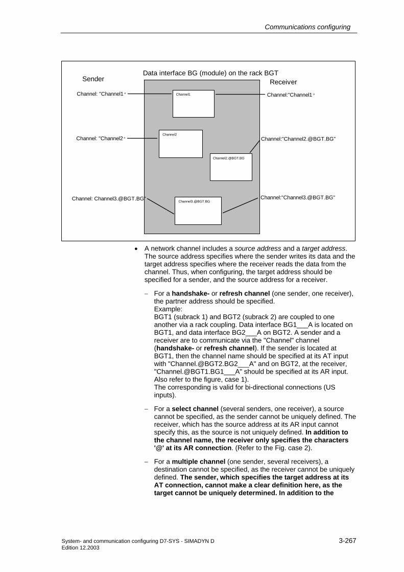
Communications configuring
System- and communication configuring D7-SYS - SIMADYN D 3-267 Edition 12.2003
Sender ReceiverData interface BG (module) on the rack BGT
Channel: "Channel1"
Channel: "Channel2"
Channel: [email protected]"
Channel:"Channel1"
Channel:"[email protected]"
Channel:"[email protected]"
Channel2
Channel1
• A network channel includes a source address and a target address.
The source address specifies where the sender writes its data and the target address specifies where the receiver reads the data from the channel. Thus, when configuring, the target address should be specified for a sender, and the source address for a receiver.
− For a handshake- or refresh channel (one sender, one receiver), the partner address should be specified. Example: BGT1 (subrack 1) and BGT2 (subrack 2) are coupled to one another via a rack coupling. Data interface BG1___A is located on BGT1, and data interface BG2___A on BGT2. A sender and a receiver are to communicate via the "Channel" channel (handshake- or refresh channel). If the sender is located at BGT1, then the channel name should be specified at its AT input with "[email protected]___A" and on BGT2, at the receiver, "[email protected]___A" should be specified at its AR input. Also refer to the figure, case 1). The corresponding is valid for bi-directional connections (US inputs).
− For a select channel (several senders, one receiver), a source cannot be specified, as the sender cannot be uniquely defined. The receiver, which has the source address at its AR input cannot specify this, as the source is not uniquely defined. In addition to the channel name, the receiver only specifies the characters '@' at its AR connection. (Refer to the Fig. case 2).
− For a multiple channel (one sender, several receivers), a destination cannot be specified, as the receiver cannot be uniquely defined. The sender, which specifies the target address at its AT connection, cannot make a clear definition here, as the target cannot be uniquely determined. In addition to the

Communications configuring
3-268 System- and communication configuring D7-SYS - SIMADYN D Edition 12.2003
channel name, the sender only specifies the '@' character at its AT connection. (Refer to Fig. case 3.)
− For a bi-directional select/multiple-connection, the sender multiple/receiver selection cannot make any specification. Case 2.) and 3.) simultaneously occur in this case. In addition to the channel name, the sender-multiple/receiver select only specifies the '@' character at its US connection. (Refer to Fig. case 4.).
The following diagram clearly illustrates the situation.
BGT1 with data interface BG1___A
Sender-Multiple:AT connection: "Channel.@"
Sender-Handshake/Refresh:AT-Anschluß: "[email protected]___A"
Sender-SelectAT connection: "[email protected]___A"
Receiver-Multiple:AR connection: "[email protected]__A"
Receiver-Handshake/Refresh:AR connection: "[email protected]___A"
Receiver-SelectAR connection: "Channel.@"
BGT2 with data interface BG2___A
Sender-Multiple/Empfänger-Select:US connection: "Channel.@"
Receiver-Multiple/Sender-SelectUS connection: "[email protected]__A"
1.)
2.)
3.)
4.)
3.23.3.2 Assigning the data interfaces to the configured NTCs
The NTC has the task to search for network channels. In this case, it cyclically searches for the data interfaces, assigned to it from @NMC.
The @NMC function block automatically determines whether an NTC function block was successfully configured. If this is the case, then it distributes the configured data interfaces to the configured NTCs. It proceeds as follows:
It consecutively assigns the data interfaces for all function blocks NTC. If all of the NTC data interfaces have been assigned, and if non-assigned data interfaces are still available, it starts again at the first NTC. The NTC are handled in the log-on sequence; the data interfaces according to increasing slot number. If there are more NTC function blocks than there are data interfaces, the superfluous NTC go into the "OFF" condition.
It does not make sense to configure NTC function blocks in different sampling times, as generally it cannot be determined which NTC are assigned to which data interface.

Communications configuring
System- and communication configuring D7-SYS - SIMADYN D 3-269 Edition 12.2003
3.23.3.3 Assigning the copying relationships of the NTC to NTD
An NTC function block can be assigned to several NTD function blocks. The NTC transfers a correctly logged-on channel to an NTD, which then handles the actual data transport. The copying relationships (links) are then consecutively transferred to the NTD function blocks. If all of the NTDs were assigned a copying relationship (link), the first NTD is re-selected. The NTD are handled in the sequence in which they were logged-on. It does not make sense to configure those NTD function blocks which are assigned to an NTC in different sampling times.
3.23.3.4 Route selection and errors
If the NTC finds a network channel, it must first define a route to the destination. Only the shortest route to the destination is considered. If there are several "shortest" routes, up to four routes are checked. If a channel cannot be logged-on up to the target node, this is not signalled to the utility FB, as principally, a subrack could still be powered-up, whereby a route would be possible to the destination.
If send- and receive channels have different channel modi or log-on parts, then this is signalled to the sender and receiver using an appropriate acknowledge index.
Network connections which have been established once, are kept, until the subrack, on which the channel is physically located (i.e. that subrack, which accommodates the CS12/13/14 module), is re-organized or shutdown.
If a subrack is powered-down and powered-up again in operation, existing network connections are automatically re-established.
3.23.3.5 Initialization of a rigid network
While the connection to a rigid network is being established, it is not permissible that a subrack which accommodates a CS22 board, on which a network connection is set-up fails. In this case, the associated CS12/13/14 module must be re-organized.
3.23.3.6 Channel modes
All four channel modi (handshake, refresh, select, multiple) are supported in the rigid network. This has effects, especially for the "select" and "multiple" modes: For several of these senders (select) or receivers (multiple), these can be located on various subracks, without having to have had channels being logged-on a multiple number of times. This is explained in more detail in the configuring example for the network status.

Communications configuring
3-270 System- and communication configuring D7-SYS - SIMADYN D Edition 12.2003
3.24 Communications utility process data
The communications utility, process data supports "pure" data transfer in the transmit- and receive directions, i.e. the function blocks only transfer process data. The data itself is neither evaluated nor logically interpreted.
There are two block classes for data transfer:
• receive- and transmit blocks: CTV and CRV
• channel marshalling blocks: CCC4 and CDC4
The CRV and CTV blocks can handle most of the communication applications.
3.24.1 Receive- and transmit blocks
There is one receive- and one transmit block. They are called CRV (communication receive virtual) and CTV (communication transmit virtual).
Using a receive- or transmit block a telegram is configured, which is transferred from or to a coupling module. The structure and contents of the telegram are defined when configuring the virtual connections.
3.24.1.1 Virtual connections
A virtual connection is an "invisible" connection between block connections. There is no interconnection drawn at the configuring interface, and only a margin connection is created.
The configuring engineer defines which values are to be transferred from block outputs or to block inputs. He does this using "connection name receive/transmit" at the receivers or transmitters and the "virtual connection name" and the "sequence number" at the block inputs or block outputs to be processed.
The connection name consists of an exclamation mark ("!") and a maximum of 6 characters (upper case letters or numbers). The character sequence is located directly after the exclamation mark (e.g. "!SEND"). The exclamation mark does not have to be configured as it is automatically generated.
A virtual connection consists of:
• virtual connection name
• sequence number
Connection name and sequence number are separated by a point (e.g. "!SEND.0056"; the point (period separator) between the connection name
Application
General
General
Connection name

Communications configuring
System- and communication configuring D7-SYS - SIMADYN D 3-271 Edition 12.2003
and the sequence number does not have to be configured as it is automatically generated).
Virtual connections can be configured at I/O with the following data types:
• BOOL (BO), BYTE (BY)
• WORD (W), DOUBLE WORD (DW)
• INTEGER (I), DOUBLE INTEGER (DI)
• REAL (R) and SDTIME (TS)
NOTE Virtual connections cannot be configured at I/O, data types STRING (S) or GLOBAL VARIABLE (GV).
The virtual connections with the same connection name (data) define a telegram with a specific structure. The sequence of the data within the telegram is defined by the sequence number. The data with the lowest number is located at the start of the telegram; that with the highest number, at the end. The sequence number defines the relative position of the data in the telegram. Gaps in the sequence numbers are ignored.
Data types
Telegram structure

Communications configuring
3-272 System- and communication configuring D7-SYS - SIMADYN D Edition 12.2003
Receiving and transmitting with virtual connections.
"!SEND.0001"
Righthand marginLefthand margin
"!SEND"
Connection data,transmit
Virtualconnections
CRTQTSYTSYEV
CTV
---
---
CTSATMODEN
Y1Y2Y3Y4Y5Y6Y7Y8
ANY_FB
----
X1X2X3X4X5X6X7X8
"!REC"
Connection data,receive
CRRQTSYTSYEV
CRV
---
---
CTSARMODEN
"!SEND.0004"
"!REC.0017"
Virtualconnections
"!REC.0003"
"!REC.0555""!REC.0555"
"CS7.X01"
Module name
"CS7.X01"
Module name
----- "!SEND2.0004"
GVBOI
W
GVBOI
W
GVSBOBO
GVSBOBO
RRRRRIII
RRRRRIII
"!SEND.0007"
-
--
--
---
- -
Fig. 3-107 Configuring: Receiving and transmitting with virtual connections
Configuring rules with reference to the example:
• The virtual connections, which belong to a virtual connection name, can be configured at block I/O with different data types (ANY_FB.Y1 "REAL" and ANY_FB.Y6 "INTEGER") and in any sequence.
• Virtual connections (receive) at block inputs can be configured a multiple number of times if the inputs have the same data type. These inputs are supplied with identical data. (ANY_FB.X4 and X5)
• The same virtual connection (transmit) with identical connection name and sequence number may not be configured a multiple number of times at block outputs.
• Several different virtual connections (transmit) can be configured at a block output (ANY_FB.Y3). The connections can differ, both in the connection name as well as in the sequence number.
Configuring example

Communications configuring
System- and communication configuring D7-SYS - SIMADYN D 3-273 Edition 12.2003
Telegram structure of the connection name/data "!REC" from the example:
Connection Virtual connection
Data type Length
ANY_FB.X2 !REC.0003 R 4
ANY_FB.X1 !REC.0017 R 4
ANY_FB.X4/X5 !REC.0555 R 4
Total length = 12 bytes
Table 3-89 Telegram structure of the connection name/data "!REC"
Telegram structure of the connection name/data "!SEND" from the example:
Connection Virtual connection
Data type Length
ANY_FB.Y1 !SEND.0001 R 4
ANY_FB.Y3 !SEND.0004 R 4
ANY_FB.Y6 !SEND.0007 I 2
Total length = 10 bytes
Table 3-90 Telegram structure of the connection name/data "!SEND"
The structure of the configured telegram appears in similar form in the CFC reference data in the view "cross-references, operands" or in the CPU MAP listing (of the CFC) under "virtual connections". The configuring can be checked using these lists.
NOTE • The virtual connection names are known on the CPU. Data from various function charts can be combined to form a telegram; however, this is not possible from various CPUs.
• Data is processed by the receive/transmit blocks in their sampling time. The sampling times of the blocks with virtual connections have no influence on the telegram processing cycle.
• The configuring engineer is responsible in ensuring that the telegram structure and length are compatible with that of the coupling partner (refer to the chapter Mode of operation of the couplings). These regulations are dependent on the secondary coupling. If an error situation develops, the receive/transmit block disables itself and makes an entry in the communications error field (e.g. PROFIBUS DP or subrack coupling), or, communications are not established (e.g. Industrial Ethernet).

Communications configuring
3-274 System- and communication configuring D7-SYS - SIMADYN D Edition 12.2003
3.24.1.2 I/O of the CRV, CTV blocks
The configured coupling module name via which communications is to be realized, is specified at input CTS of the block. For CS7 or T400 modules, it is also necessary to specify the connector (X01, X02 or X03).
The address parameter for communications is specified at input AR, AT. It consists of a channel name and the optional address stages. The significance of the address parameters is dependent on the coupling used. (e.g. PROFIBUS or DUST).
The data transfer mode is configured at the MOD input (e.g. "R" for refresh or "H" for handshake)
Input EN defines whether data is to be transferred in the current operating cycle.
The virtual connection name, receive or send is configured at input CRR or CRT.
3.24.2 Channel marshalling blocks CCC4 and CDC4
Channel marshalling blocks are used to split-up or combine channels.
3.24.2.1 Group block CCC4
The CCC4 function block (Communication Collect Channel 4) combines up to 4 channels to form one. The channels may have different address data, be located at different interfaces and have different data transfer modi as well as channel lengths.
In order that the function block can operate, at least 2 channels must be combined (CT1- and CT2 input data are mandatory).
If only 2 channels are to be combined, then a "0" (zero) should be configured at initialization inputs CT3 and CT4. In this case, connections AR3, AR4, MO3, MO4, LT3 and LT4 are no longer evaluated.
The transmit channel is specified at inputs CTS, AT and MOD. The length of the net data to be transmitted is obtained from the sum of the receive data. Receive channels 1-4 are combined, one after the other to form a large net data block.
Inputs CTS
Input AR, AT
Input MOD
Input EN
Inputs CRR, CRT
Application
General
Prerequisites
Data entries at connections CT3, CT4
Data entries at input CTS, AT, MOD

Communications configuring
System- and communication configuring D7-SYS - SIMADYN D 3-275 Edition 12.2003
Receive channel 1 with 100 bytes
Receive channel 4 with 75 bytes
Receive channel 3 with 125 bytes
Receive channel 2 with 200 bytes
Receive channel 1 with 100 bytes
Receive channel 2 with 200 bytes
Receive channel 3 with 125 bytes
Receive channel 4 with 75 bytes
Transmitchannelwith 500 bytes
Fig. 3-108 Combining 4 receive channels to form a transmit channel
--
EKAN1.24EKAN2EKAN3EKAN4SKAN
HSRMR
10020012575
1
Righthand marginLefthand margin
Configured module name on which the da tai t fof the receive channels a re loca ted
Da ta transfer mod i ofthreceive channels
QTSYEV
CCC4
---------------
GVGVGVGVGVSSSSS
SSSSSIIIIBO
BOW
CT1CT2CT3CT4CTSAR1AR2AR3AR4ATMO1MO2MO3MO4MODLT1LT2LT3LT4EN
CS7.X01CS120ACS210AD01_P1
CS7.X02
Data transfer mode ofthtransmit c hannel
Configured module name on whic h the da ta interfac e of the transmit c hannel is loc a ted
Net da ta lengths of therec eive c hannels
Address da ta for therec eive c hannels
Fig. 3-109 Configuring example: CCC4 connections when combining 4 channels
3.24.2.2 Distribution block CDC4
Example
General

Communications configuring
3-276 System- and communication configuring D7-SYS - SIMADYN D Edition 12.2003
The function block CDC4 (Communication Distribute Channel 4), sub-divides a channel in up to 4 channels. The channels may have different address data, be located on different data interfaces, and have different data transfer modi as well as channel lengths.
In order that the function block can operate, the receive channel must be sub-divided into at least 2 transmit channels (CT1- and CT2 input data are mandatory).
When sub-dividing a channel into only 2 channels, a "0" (zero) must be configured at initialization inputs CT3 and CT4. AR3, AR4, MO3, MO4, LT3 and LT4 are, in this case, no longer evaluated.
The receive channel is specified at inputs CTS, AT and MOD. The length of the net data to be received is obtained from the sum of the transmit data.
NOTE If one of the transmit channels is configured in the handshake mode and precisely this channel is not read-out on the receive side, then the CDC4 function block cannot operate until this one channel has been read-out. In this case, the block is temporarily inhibited.
3.24.2.3 Compatible net data structure
For blocks CCC4 and CDC4, the net data are unstructured (data type, octet string). Thus, they are compatible to any net data structure. In order that the transmitter and the associated receiver can correctly synchronize with one another, only the net data lengths must be identical.
3.24.3 Diagnostic outputs
After each processing cycle, the result of the processed data interface(s) is output at the YEV output of the transmit- and receive blocks as well as the channel marshalling blocks (CTV, CRV, CCC4, CDC4). The YEV output is the WORD type; the 16 bits are sub-divided into three areas:
15 14 13 12 11 10 9 8 7 6 5 4 3 2 1 0 Channel statuses
(only CCC4, CDC4) Channel assignment (only CCC4, CDC4)
Fault cause
Table 3-91 Diagnostic outputs
3.24.3.1 Fault/error cause
The possible fault/error cause is displayed in bits 0-7 in the form of a hexadecimal value (this should not be evaluated bit-coded):
Prerequisites
Data entries at inputs CT3, CT4
Data entries at inputs CTS, AT, MOD
General
Hexadecimal value

Communications configuring
System- and communication configuring D7-SYS - SIMADYN D 3-277 Edition 12.2003
Hex. Value
Significance Counter-measure
0 No fault/error, data transfer was successful.
1 Block was permanently disabled after initialization due to a configuring error or after an internal error (refer to the communications error field or YTS output for detailed information).
Correct configuring.
2 Communications partner not ready or the communications link was physically interrupted (refer to YTS for more detailed information).
Check coupling partner, cables and connector.
3 Communications partner is not transmitting/receiving (depending on the enable input of the communications partner). The function block is not transmitting/receiving because the communications partner has signaled that it is not transmitting data.
Activate the communications partner
4 Only for transmitters: Data cannot be transmitted. Normally, in the handshake/select mode: The communications partner has still not read-out the last data; seldom in the refresh mode: Communications partner is presently reading).
Configure the transmitter to be slower or the receiver to be faster.
5 Only for receivers: No new data could be received (the communications partner hasn't transmitted any new data since the last data was received).
Configure the receiver to be slower or the transmitter faster.
6 Inconsistent data (subrack coupling: when shutting down the master subrack)
None (proceed with new initialization)
7 Only select transmitters: channel occupied. Another function block is presently transmitting.
All select transmitters can coordinate via the enable input.
8 Only multiple receivers: Reception erroneous. Data read-out took too long; in the meantime, the transmitter has already written new data into the channel.
Configure receivers in a faster (higher-priority) sampling time.
9 Still being initiated. Transmit/receive operation was therefore not able to be started.
Table 3-92 Fault/error cause
In the handshake mode, these numbers can sporadically occur which is quite acceptable. This is because full synchronization between the communications partner is not always possible. Receivers and transmitters should operate approximately in the same cycle.
In the refresh mode, these numbers should not occur if the transmitter is always faster than the receiver.
3.24.3.2 Channel assignment
The area is only used by the CCC4 and CDC4 function blocks. In this case, a number indicates which channel is involved with the error (bits 0-7). As the channel marshalling block can process up to five channels, the numbering is as follows:
Comments to numbers 4 and 5
General information

Communications configuring
3-278 System- and communication configuring D7-SYS - SIMADYN D Edition 12.2003
Number Channel 0 Main transmitter/receiver (corresponding to CTS-, AT- or AR-
connection data).
1 Transmit/receive part 1 corresponding to the CT1- and AT1- or AR1 connection data)
2 Transmit/receive part 2
3 Transmit/receive part 3
4 Transmit/receive part 4
Table 3-93 Channel assignment
3.24.3.3 Channel statuses
The area is only used by function blocks CCC4 and CDC4. This indicates which channels are not operating error-free.
In the "channel statuses" range it is specified on which channel faults were identified when processing the channel
This area is bit-structured:
• 1=no fault
• 0=fault
Bit Channel 11 Transmit/receive part 1
12 Transmit/receive part 2
13 Transmit/receive part 3
14 Transmit/receive part 4
15 Main transmitters/receivers
Table 3-94 Channel statuses
3.24.4 Introduction – "Pointer-based communication blocks"
Up to D7-SYS Version 6, serial or parallel data transfer operations for SIMATIC control systems were configured using the so-called "virtual communication couplings" methods (shown in CFC charts e.g.: "!VNAME.0001").
Exception: The fiber-optic cable drive coupling SIMOLINK is configured using special SIMOLINK blocks.
General

Communications configuring
System- and communication configuring D7-SYS - SIMADYN D 3-279 Edition 12.2003
From D7-SYS Version 6, communication links, for example PROFIBUS-DP, SIMATIC-CPU ↔ FM 458-1 DP as well as for SIMATIC TDC or T400 and SIMADYN D can be alternatively configured using communication blocks which have become recently available.
In this case, interface data is accessed from the CFC screen using new blocks, which are inter-connected using a special pointer interface.
Both of these configuring methods (virtual interconnections and pointer-based communications) can be used together on the same hardware platform, in the same configuring (application software) and even for the same interface.
3.24.4.1 Principle mode of operation
Telegram blocks (CRV_T, CTV_P and S7RD_P, S7WR_P) allow access to the receiving or to the sending data blocks (telegrams) by providing a pointer to the particular data block.
This pointer is connected to read/write blocks (DRD…, DWR…). Together with an offset, a write block can save the data at its input connection at the required location in the buffer. A read block then retrieves the appropriate data from the specified location of the receive buffer and makes it available at its output.
This means that in principle, a virtual interconnection is replaced by a (read/write) block and a "normal" CFC connection.
3.24.4.2 Applications
Pointer-based communications are especially advantageous where large amounts of data are involved. For large amounts of data, it is simpler and faster to configure and change and interconnections are more flexible.
Large data quantities

Communications configuring
3-280 System- and communication configuring D7-SYS - SIMADYN D Edition 12.2003
128 bytes can be transferred from the FM 458-1 DP to the S7-CPU in each direction via the I/O area of the P bus.
Using the new S7RD_P/S7WR_P blocks, all 128 bytes can be copied into a buffer using a block and that with an optimized computation time. This buffer can then be accessed flexibly using read/write blocks via the pointer interface. Indexed access is also possible
Sub-areas can also be accessed using offset and length data.
Data can be saved in a data memory which can be universally used. This data memory can then be accessed using read/write blocks via a pointer interface. Several similar buffers can be set-up in this data block. This means, for example, that recipes can be easily saved and called-up.
3.24.4.3 Features of pointer-based communications
• When generating CFC charts, the configuring time and costs are reduced, especially if very many virtual connections had to be generated.
• Connections to the telegram data can be newly inserted and changed online (pointer, buffer offset).
• Communication connections can be copied with or within chart blocks and centrally changed with them. This means that it is especially simple and quickly to configure, for example, similar communication links to a large number of drives.
• Telegram buffer data can be accessed indexed using 2 offset data. This means that extremely simple modular programs (e.g. chart blocks) can be generated and used.
• Larger data quantities can be transparently processed (e.g. blockwise) (copied), e.g. using the copy block CPY_P in data block DB_P.
• For FM 458-1 DP:
− using "B-Receive" (BRCV) high quantities of data can be transferred from the S7-CPU to the FM 458-1 DP via the K bus.
− 128 bytes can be simply configured and quickly transferred with low computation overhead via the I/O area of the P bus.
• A special read/write block is available for every data type (BYTE, INT, DINT, REAL).
• Before accessing REAL data, the type is checked.
• These configuring possibilities can be principally used for all of the SIMATIC control system platforms. This means FM 458-1 DP, SIMATIC TDC, T400 and SIMADYN D. The reason for this is that block processing is independent of the subordinate (secondary) hardware.
Access to the I/O area (P bus) for FM 458-1 DP
Saving data in a data block
For all platforms and interfaces of the SIMATIC control systems

Communications configuring
System- and communication configuring D7-SYS - SIMADYN D 3-281 Edition 12.2003
• For the same reason, this type of block communications can be principally used for all types of serial and parallel data transfer routes, where today "virtual communications" are used.
3.24.4.4 Associated function blocks
The blocks which can be used are arranged under the family names "ZeigrKom" or "PointCom" in the CFC block Catalog.
In order to be able to simply identify and easily assign to this block group, the blocks, whose function already corresponds to existing blocks, and which now output a pointer for this application, have a "_P" (pointer) at the end of the name.
Type name Function CPY_P Copying buffer areas
CRV_P Telegram block, receive (interface processing)
CTV_P Telegram block, send (interface processing)
DB_P Data block
DRD Data Read REAL DRD_D Data Read DINT DRD_I Data Read INT DRD_8 Data Read 8*REAL DRD_8D Data Read 8*DINT
DRD_8I Data Read 8*DINT
DRD_BY Data Read BYTE DWR Data Write REAL DWR_D Data Write DINT DWR_I Data Write INT DWR_8 Data Write 8*REAL DWR_8D Data Write 8*DINT
DWR_8I Data Write 8*INT
DWD_BY Data Write BYTE
S7RD_P Receive 128 bytes via a P bus (only for FM 458-1 DP)
S7WR_P Send 128 bytes via a P bus (only for FM 458-1 DP)
BRCV Block data receive via S7 connection (only for FM 458-1 DP)
3.24.4.5 Pointer interface
For pointer-based communications, a pointer is transferred to the telegram data buffer between the blocks involved:

Communications configuring
3-282 System- and communication configuring D7-SYS - SIMADYN D Edition 12.2003
This pointer is actually a pointer which includes a structure, which in addition to the pointer to the net data also has information for monitoring purposes. This data includes, for example, the sampling time, block class, byte/word swap. It has the connection comment "ZeigPuffer".
3.24.4.6 Configuring information and instructions
• The telegram blocks as well as the read/write blocks must be configured in the same sampling time in order to ensure consistency (this is checked when initializing).
• Offset data must be carefully entered. a) For pointer-based communications, the configuring engineer must precisely observe the offset (in bytes) of the 16-bit value (INT) or 32-bit value (REAL, DINT) to be addressed. b) The offset must always be smaller than the buffer size. Before accessing buffer data, a check is made as to whether the area (range) has been exceeded because of an offset which has been set too high.
• If data is transferred to a PROFIBUS-DP station or to a SIMATIC CPU, then bytes (for INT) and, where relevant, words of the value to be transferred (for REAL, DINT) must be swapped. The read/write blocks have a "Swap" connection – SWP – for this specific purpose.
• In order to transfer telegrams via an interface, initially, it is sufficient to just configure the telegram block with the appropriate lengths data (CRV_T, CTV_P and S7RD_P, S7WR_P). Read/write blocks still don't have to be configured. This means that the interface can be tested or the computation time load through the interface configured using, for example, few resources.
3.24.4.7 Examples of CFC screenshots

Communications configuring
System- and communication configuring D7-SYS - SIMADYN D 3-283 Edition 12.2003
Fig. 3-110 CFC screenshot: Data transfer with telegram blocks and read/write blocks; here, for the interface P bus of the
FM 458-1 DP (@CPB); bytes/words must be swapped due to the data management on the SIMATIC-CPU: SWP(Swap)=1

Communications configuring
3-284 System- and communication configuring D7-SYS - SIMADYN D Edition 12.2003
Fig. 3-111 CFC screenshot: Data transfer SIMATIC-CPU ↔ FM 458-1 DP via P bus I/O area

Communications configuring
System- and communication configuring D7-SYS - SIMADYN D 3-285 Edition 12.2003
Fig. 3-112 CFC screenshot: Indexed addressing of the telegram data with 2 offsets

Communications configuring
3-286 System- and communication configuring D7-SYS - SIMADYN D Edition 12.2003
Fig. 3-113 CFC screenshot: Re-saving 2 received telegrams in a data block and single accesses to the data memory

Communications configuring
System- and communication configuring D7-SYS - SIMADYN D 3-287 Edition 12.2003
Fig. 3-114 CFC screenshot: Large data quantities received from a SIMATIC CPU via K bus using BRCV

Communications configuring
3-288 System- and communication configuring D7-SYS - SIMADYN D Edition 12.2003
3.25 Communications utility service
• Provides a pool of information functions so that the user has access to system information on the CPU.
• Resource for start-up (commissioning) and debugging.
The configured data (setpoints/actual values) are displayed and/or changed here, as well as the software optimized (interconnections, controller times modified.
Causes of system faults (crash, run-up problems) and disturbances, where the cause is within the CPU module, can be determined here.
All of the communication utility, service activities are controlled via tasks, which are received via a coupling (corresponding to the data entries at the CTS and US inputs).
Operator control devices for the communications utility, service:
• Windows 95/NT-PC with CFC (e.g. in the test mode)
• Windows 95/NT-PC with SIMATIC Manager
• Windows 95/NT-PC with basic IBS (basic commissioning tool)
Using CFC, SIMATIC Manager or the basic service tool, it is possible to access a CPU via the local RS232 interface of the CPU. No additional configuring is required.
NOTE You can read-out the CPU module information using the CFC and the SIMATIC Manager. Additional information ont he CPU module, refer to the User Documentation "SIMADYN D, Basis software D7-SYS", Section "Diagnostics".
Each CPU of this subrack can be accessed via a DUST1- or MPI coupling configured in the subrack.
The following must be configured:
• One per subrack:
− DUST1 coupling: One SS4 module and a central block DUST1 coupling "@CSD01" or
− MPI coupling: One SS52/MPI module and a central block MPI coupling "@CSMPI"
• At least one per CPU:
− "SER" service function block.
Brief description
Start-up
Debugging
Local service
Central service

Communications configuring
System- and communication configuring D7-SYS - SIMADYN D 3-289 Edition 12.2003
Additional information Refer to the Chapter "DUST1 coupling" and Chapter "MPI coupling" for details on the DUST1 and MPI couplings.
3.25.1 Function block SER
"SER" function has a coupling connection. It can be configured several times for each CPU.
The CTS input designates the coupling module and the interface via which an operator control device is connected.
A channel name and address stage 1 is specified at input US.
• Channel name
− max. 6 characters
− ASCII characters with the exception of "point" and @
− the channel name on a data interface must be unique.
• Enter "." after the channel name
• Address stage 1
− CPU slot number. The operator control program addresses the CPU via this number.
− The data entry must have two digits: e.g. "01", "02", ..., "24".
SER-
--
-
CTSUSLT
QTSYTS
'CS7.X01'
'ser1.01'
240
1st CPU at slot 1
SER---
-
CTSUSLT
QTSYTS
'CS7.X01''ser2.04'
240
2nd CPU at slot 4
@CSD01--
-
-
-
-
-
CTSBDRTWUCDV
ECLECOCDMQTS
19200240
'CS7.X01'
0
Fig. 3-115 Example: Configuring with CFC
Data entries at the connections
Example: Configuring with CFC

Communications configuring
3-290 System- and communication configuring D7-SYS - SIMADYN D Edition 12.2003
3.25.2 System load, response times
Service is actually processed in a sampling time of approximately 32 ms. (The sampling time, specified at the SER blocks is therefore not decisive for processing.) In the sampling time used, the service blocks have a certain computation time available, and more precisely, a maximum of one basic clock cycle (T0).
NOTE The ratio of the basic clock cycle T0 to the sampling time used defines the CPU performance available and therefore the system load.
Basic clock cycle T0=1ms; selected sampling time=32ms
• Every 32 ms, 1 ms is reserved for the service utility
• System load=1 ms / 32 ms=0.03125=3.125 %
Basic clock cycle T0=2ms; selected sampling time=16ms
• Every 16 ms, 2ms is reserved for the service utility
• System load=2 ms/16 ms=0.125=12.5 %
The computation time available is evenly distributed among all of the service blocks (there is no priority). This means, that as long as time is available, if possible, all SER blocks are executed once. An SER block processes a maximum of one task per each clock cycle. If the reserved computation time isn't fully used, for example, as there is no task to process, then this computation time is made accessible to the system.
For multiple configuring and simultaneous access to system resources which are only available once (e.g. EEPROM), the first to request a resource is the first to receive it. All others are rejected and an error message is output, at the latest after 1 s ("resource occupied").
General
Example 1
Example 2
Computation time
Resource distribution

Communications configuring
System- and communication configuring D7-SYS - SIMADYN D 3-291 Edition 12.2003
3.26 Communications utility time of day synchronization
The communications utility, time of day synchronization allows a unified system time to be provided over several SIMADYN D subracks.
The following can be used as time source:
• a time transmitter can be connected via an "Industrial Ethernet" (SINEC H1).
• the MM3 communications buffer module
• the CPU inserted to the far left in a subrack
The time is distributed:
• within a SIMADYN D subrack via a communications buffer module
• to other SIMADYN D subracks via the subrack coupling
Precisely one function block RTCM should be configured per subrack to distribute the system time.
Further information to configure function blocks, refer to the user documentation "SIMADYN D, Function Block Library".
The following function blocks are used to read-out the system time:
• RTCABS: absolute time in the date/time of day format
• RTCREL: relative time in seconds since 01.01.88
These blocks can be configured as required.
General
Time
Function block

Communications configuring
3-292 System- and communication configuring D7-SYS - SIMADYN D Edition 12.2003
3.27 Communications with SIMATIC Operator Panels
A configuring engineer will be shown how to implement a coupling from SIMADYN D to a SIMATIC OP7 using this configuring software example.
NOTE Proceed in a similar fashion when configuring couplings to the OP27, OP37 SIMATIC Operator Panels and the TP37 SIMATIC Touch Panel.
The example described here, includes all of the available SIMADYN function blocks, and shows how they are essentially used. The functional scope of the configuring software example has been consciously kept extremely low, so that you can quickly get to grips with the subject. It is simply possible to expand the functionality and/or the hardware components. However, the information provided in the applicable function block documentation must be observed.
The designations used for data blocks, flags, variables etc. have been randomly selected, and are only binding for this particular configuration software example.
NOTE • When saving values which have been changed using SIMATIC Ops, this is realized on the SIMADYN D CPU in the SAVE area.
• When the battery back-up fails, the configured value at the input is used as default.
The structure of these configuring instructions represents the sequence of the various operating steps, with which the complete configuring software can be generated. However, it should only be considered as a recommendation, and is not mandatory.
We are assuming that you know how to handle the SIMATIC Manager (including HWConfig and CFC), configuring SIMADYN D as well as configuring OP7 with ProTool/Lite.
Literature which is available on these subjects:
• SIMADYN D User Manuals
• SIMATIC Equipment Manual OP7/17
• SIMATIC HMI, User Manual ProTool/Lite configuring software
3.27.1 Configuring example
The configuring software example supports the following OP7 functions:
• Reading and writing variables
• Output of operating messages
Introduction
Prerequisites
Functional scope

Communications configuring
System- and communication configuring D7-SYS - SIMADYN D 3-293 Edition 12.2003
• Output of alarm messages including acknowledgment
• Interrogating the function keyboard
• Updating date and time
The following equipment and components are selected and located as follows for the configuration example:
SIEMENS SIMATIC OP7
7 8 9
654
1 2 3
. 0 +/- SHIFT INSDEL HELP
ESC
ACK
ENTER
F1
K1
F2 F3 F4
K2 K3 K4
SS 5
2
SIMADYN DSIEMENS
S 01 S 02 S 03 S 04 S 05 S 06 S 07 S 08 S 09 S 10 S 11 S 12
PM 5
CS
7
SIE
ME
NS
SIE
ME
NS
SIEM
ENS
3
2
1
5
4
7
6
1
2
3
4
Subrack SRT6Processor module PM5Program memory submodule MS5Communications module CS7
5
6
7
Communications submodule SS52SIMATIC Operator Panel OP7PPMPI bus cable
Fig. 3-116 Setting-up the configuring example
3.27.2 Configuring SIMADYN D
All of the configuring, which involves SIMADYN D, is made in the SIMATIC Manager. The work is divided into the "Selecting components in HWConfig" and "Configuring with CFC" sections.
3.27.2.1 Selecting the components in HWConfig
The configuration example is configured in HWConfig. The standard program inputs can be accepted. The only changes involved:
• Sampling time T4 of the PM5 = 64ms
Hardware
General information

Communications configuring
3-294 System- and communication configuring D7-SYS - SIMADYN D Edition 12.2003
• Highest MPI address of the SS52 = 126 (126 is entered as standard in ProTool/Lite)
The following hardware configuration can be seen after work has been completed in HWConfig:
Fig. 3-117 Screenshot of the completed HWConfig menu
3.27.2.2 Configuring with CFC
After executing "Save and compile" in the "HWConfig", the "D01_P1" symbol was inserted in the SIMATIC Manager below the "SIMADYN D station".
A new chart, called "OP7" is added, in the associated chart container, to the existing charts "@SIMD1" and "@SIMD2". All of the additional configuring work will now be made in a new chart called "OP7".
Fig. 3-118 Screenshot of the completed chart container
• All of the function blocks to be configured are configured in the sequence level T4.
• If not explicitly listed, the standard assignments of the function block connections are kept.
Inserting a new chart
Agreements

Communications configuring
System- and communication configuring D7-SYS - SIMADYN D 3-295 Edition 12.2003
• Only the relevant connections are listed in the following configuring tables.
3.27.2.2.1 Initializing the OP7
The function blocks @CSMPI and S7OS are connected to the configured coupling module (SS52-MPI on CS7) via the CTS inputs. This establishes the connection between SIMADYN D and OP7.
FB Connection Connection assignment (significance) @CSMPI CTS D0200C.X01
(global operand, module name)
S7OS CTS D0200C.X01 (global operand, module name)
US testop.01 (address parameter)
Table 3-95 Connection assignment @CSMPI and S7OS
Fig. 3-119 Initializing the OP7 on the MPI bus
3.27.2.2.2 Reading function block connections (I/O)
A counter was configured for this function, which continually increments from the initial value ("0") up to a final value ("50"). It then automatically resets itself and starts again from the beginning. Output Y (counter status) of the CTR is interlocked with a global operand (OP connection), whose contents are read-out at OP7.
NOTE The flag No., specified under SIMADYN D for the OP connection, must also be assigned the configured variables under ProTool/Lite.
Brief description
Configured software
CFC chart
Brief description

Communications configuring
3-296 System- and communication configuring D7-SYS - SIMADYN D Edition 12.2003
FB Connection Connection assignment (significance) BF T 500ms (time constant)
CTR LU 50 (counter upper limit)
Y Symbol name: Z_output Flag No.: MW10
(global operand, OP connection)
Table 3-96 Connection assignment, BF and CTR
Fig. 3-120 Reading function block connections
3.27.2.2.3 Writing function block connections
A value from OP7 is read-in using a global operand (OP connection), fed through a dummy block (NOP1_I), and is sent back to the OP7 with an additional global operand (OP connection); it is read-out from the OP7.
NOTE The flag No. for the OP connections, specified under SIMADYN D, must also be assigned the configured variables under ProTool/Lite.
FB Connection Connection assignment (significance) NOP1_I X Symbol name: OP_SOLL
Flag No.: MW20 (global operand, OP connection)
Y Symbol name: OP_IST Flag No.: MW30
(global operand, OP connection)
Table 3-97 Connection assignment, NOP1_I
Configuring software
CFC chart
Brief description
Configured software

Communications configuring
System- and communication configuring D7-SYS - SIMADYN D 3-297 Edition 12.2003
Fig. 3-121 Writing into function block connections (I/O)
3.27.2.2.4 Configuring events
If the counter starts a new count loop, an event is output. Output QO of function block CTR outputs the signal. This signal is extended (FB PDF), converted from the "boolean" format into the "word" format (FB B_W), and transferred to function block S7EMA as the first event message word.
The S7EMA is assigned a virtual data block number for the user data area "event messages" via a global operand (OP connection).
NOTE The data block No., specified under SIMADYN D for the OP connection, must also be assigned the configured area pointer for event messages under ProTool/Lite.
FB Connection Connection assignment (significance) PDF I Function block CTR, output QO
(event message signal)
T 5000ms (time constant)
B_W (Conversion from boolean to word)
S7EMA XDB Symbol name: BM Data block No: DB1
(global operand, OP connection)
Table 3-98 Connection assignment, @CSMPI and S7OS
CFC chart
Brief descriptions
Configured software

Communications configuring
3-298 System- and communication configuring D7-SYS - SIMADYN D Edition 12.2003
Fig. 3-122 Configuring event messages
3.27.2.2.5 Configuring alarm messages
If the counter starts a new count loop a alarm message is output (at the same time as the event message) . Output QO of function block CTR supplies the signal. This signal is converted from the "boolean" format into the "word" format (FB B_W), and is transferred to function block S7AMA as the first event message word.
S7AMA is assigned a virtual data block No. for the user data area "alarm messages" via a global operand (OP connection).
NOTE The data block No. for the OP connection, assigned under SIMADYN D, must also be assigned the configured area pointer for alarm messages under ProTool/Lite.
FB Connection Connection assignment (significance) B_W I1 Function block CTR, output QO
(signal for the alarm message)
S7AMA XDB Symbol name: SM Data block No.: DB10
(global operand, OP connection)
Table 3-99 Connection assignment, B_W and S7AMA
CFC chart
Brief description
Configured software

Communications configuring
System- and communication configuring D7-SYS - SIMADYN D 3-299 Edition 12.2003
Fig. 3-123 Configuring alarm messages
3.27.2.2.6 Configuring the function keyboard
The configuring of the function keyboard includes, on the SIMADYN D side, only the S7FKA function block. The actual assignment of the key functions is realized under ProTool/Lite.
S7FKA is assigned, via a global operand (OP connection) a virtual data block No. for the user data area "function keyboard image".
NOTE The data block No., assigned under SIMADYN D, for the OP connection, must also be assigned the configured area pointer for the function keyboard under ProTool/Lite.
FB Connection Connection assignment (significance) S7FKA XDB Symbol name: FK_Tast
Data block No.: DB20 (global operand, OP connection)
Table 3-100 Connection assignment, S7FKA
CFC chart
Brief description
Configured software

Communications configuring
3-300 System- and communication configuring D7-SYS - SIMADYN D Edition 12.2003
Fig. 3-124 Configuring the function keyboard
3.27.2.2.7 Configuring the interface area
The time and date of the OP7 is cyclically updated by SIMADYN D using this function. S7IA is assigned, via a global operand (OP connection) a virtual data block No. for the user data area "interface area" .
NOTE The data block No., assigned under SIMADYN D, for the OP connection, must also be assigned the configured area pointer for the interface area under ProTool/Lite.
FB Connection Connection assignment (significance) S7IA XDB Symbol name: SB
Data block No: DB30 (global operand, OP connection)
Fig. 3-125 Defining the interface area
CFC chart
Brief description
Configured software
CFC chart

Communications configuring
System- and communication configuring D7-SYS - SIMADYN D 3-301 Edition 12.2003
3.27.2.3 Importing the symbol table
While configuring the CPU in HWConfig an empty symbol table is automatically set-up, which will later accept the symbol names configured using CFC. The file with the symbol names must then be imported into the symbol table when the CFC has been configured.
Fig. 3-126 "Symbol" icon in the chart container
The symbol editor is opened from the chart container by double-clicking on "Symbols".
The symbol file (symbol.asc) is loaded in the symbol table using the menu command "Import table...".
NOTE If changes are made in the symbol file in the CFC between two compilations, then a message to this effect is output. This message can also be taken from the actual memory path of the symbol file.
The following diagram shows the complete symbol table of the test software after having been imported:
Fig. 3-127 Symbol table with imported symbol file
The symbol table is saved and the operation completed using "Save table".
General information
Symbol editor

Communications configuring
3-302 System- and communication configuring D7-SYS - SIMADYN D Edition 12.2003
3.27.3 Configuring the OP7 with ProTool/Lite
The configuring of OP7 is not described in detail here. If not explicitly mentioned, when configuring, the standard settings can be taken from ProTool/Lite.
NOTE For error-free communications, it is absolutely necessary, that the flag- and data block numbers, configured in CFC, are transferred for the individual functions, unchanged, into ProTool/Lite.
CFC generates a symbol table, in which all of the flags and data blocks used are saved. This symbol table must be imported for the configuring work for ProTool/Lite.
The symbol names, configured in CFC for the OP7 configuring, can now be used in ProTool/Lite.
Configured software with displays (including variables to read and write values), event- and alarm messages as well as configured function keys must be generated for the OP7.
The following table provides an overview of the required configuring components with the associated values, harmonized and adapted to the CFC configured software:
Configured software Setting Control SIMATIC S7-300/400
MPI settings Communications partner slot: 1
Variables to read the function block connections (I/O)
Symbol name: Z_Ausgabe (VAR_1: Format "INT", type "A" area "M", MW10)
Variables to write into the function block connections (I/O)
Symbol name: OP_SOLL (VAR_2: Format "INT", type "E" area "M", MW20) Symbol name: OP_IST (VAR_3: Format "INT", type "A" area "M", MW30)
Area pointer, event messages Symbol name: BM (DB1, DBW0, length "8" words)
Area pointer, alarm messages Symbol name: SM (DB10, DBW0, length "8" words)
Area pointer, acknowledge PLC DB10, DBW16, length "8" words
Area pointer, acknowledge OP DB10, DBW32, length "8" words
Area pointer, function keyboard Symbol name: FK_Tast (DB20, DBW0, length "1" word)
Area pointer, interface area Symbol name: SB (DB30, DBW0, length "16" words)
General information
Symbol table
Configuring software

Communications configuring
System- and communication configuring D7-SYS - SIMADYN D 3-303 Edition 12.2003
3.27.4 Application information
3.27.4.1 Computation times
The computation times of the function blocks are dependent on the application.
The computation times of the function blocks for an OP7 are listed in the following table. Each additional configured OP7 correspondingly increases the computation time.
S7OS S7EMA S7AMA S7FKA S7IA One OP7 120 2 33 22 18
Each additional OP7 55 2 33 22 18
General information
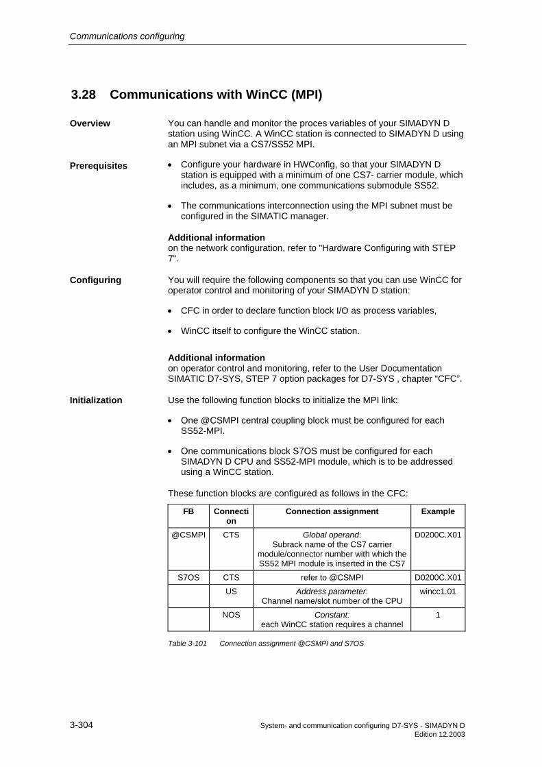
Communications configuring
3-304 System- and communication configuring D7-SYS - SIMADYN D Edition 12.2003
3.28 Communications with WinCC (MPI)
You can handle and monitor the proces variables of your SIMADYN D station using WinCC. A WinCC station is connected to SIMADYN D using an MPI subnet via a CS7/SS52 MPI.
• Configure your hardware in HWConfig, so that your SIMADYN D station is equipped with a minimum of one CS7- carrier module, which includes, as a minimum, one communications submodule SS52.
• The communications interconnection using the MPI subnet must be configured in the SIMATIC manager.
Additional information on the network configuration, refer to "Hardware Configuring with STEP 7".
You will require the following components so that you can use WinCC for operator control and monitoring of your SIMADYN D station:
• CFC in order to declare function block I/O as process variables,
• WinCC itself to configure the WinCC station.
Additional information on operator control and monitoring, refer to the User Documentation SIMATIC D7-SYS, STEP 7 option packages for D7-SYS , chapter “CFC”.
Use the following function blocks to initialize the MPI link:
• One @CSMPI central coupling block must be configured for each SS52-MPI.
• One communications block S7OS must be configured for each SIMADYN D CPU and SS52-MPI module, which is to be addressed using a WinCC station.
These function blocks are configured as follows in the CFC:
FB Connection
Connection assignment Example
@CSMPI CTS Global operand: Subrack name of the CS7 carrier
module/connector number with which the SS52 MPI module is inserted in the CS7
D0200C.X01
S7OS CTS refer to @CSMPI D0200C.X01
US Address parameter: Channel name/slot number of the CPU
wincc1.01
NOS Constant: each WinCC station requires a channel
1
Table 3-101 Connection assignment @CSMPI and S7OS
Overview
Prerequisites
Configuring
Initialization

Communications configuring
System- and communication configuring D7-SYS - SIMADYN D 3-305 Edition 12.2003
NOTE • WinCC saves changed values in the SIMADYN D-CPU in the SAVE area.
• When the battery back-up fails, the configured value of the input is used as default value.

Communications configuring
3-306 System- and communication configuring D7-SYS - SIMADYN D Edition 12.2003
3.29 Communications with WinCC (SINEC H1)
This User Manual shows you how you can couple WinCC to SIMADYN D via a SINEC H1 coupling using a simple example of the configuring software. All of the necessary configuring steps ( including the hardware- and software requirements) are described. The handling of the necessary software tools is not described here, but a reference is made to the appropriate User Manuals.
3.29.1 Prerequisites
SIMADYN D channel-DLL Software prerequisites • WinCC-Systemsoftware:
from version 4.02 for Windows 95 und Windows NT 4.0 • SIMATIC-NET-Driver (Industrial Ethernet):
TF-1613 / Windows NT 4.0 Order No. (SIMADYN-D-PMC Industrial Ethernet) 2XV9450-1WC43-0AX0 Further information Siemens AG Industrial Solutions and Services IT Plant Solutions I&S IT PS 3 Werner-von-Siemens-Straße, 60 91052 Erlangen Contact: your IT4Industry Team Phone: +49 (91 31) 7-4 61 11 Fax: +49 (91 31) 7-4 47 57 E-Mail: [email protected] WWW: http://www. it4industry.de
Tools PROBI: The configuring package PROBI is component of every SIMADYN D-PMC licence.
SINEC NML configuring tool for CSH11
Table 3-102 Software prerequisites
NOTE The SIMADYN D-PMC channel-Dll can only be used in conjunction with WinCC V4.02. For the configuring example used here, the channel DLL must be operated with SIMADYN D PMC Ethernet Layer 4 (Win95/NT4.0, TF1613 V3.1). The software is installed via a setup routine, which is provided on the product software floppy disk.
The PMC channel DLL can only be inserted in the tag management from WinCC, if the associated communications driver SIMATIC NET TF1613 is installed. Installation is realized via a setup which is provided on the CD-ROM of the SIMATIC NET product version.
Introduction
Software

Communications configuring
System- and communication configuring D7-SYS - SIMADYN D 3-307 Edition 12.2003
PC configuring station:
SIMATIC NET plug-in cable 727-1 for INDUSTRIAL ETHERNET l network card SIMATIC NET CP1613
Table 3-103 Hardware prerequisites
NOTE A CP1613 must be installed in the PC.
System: SIMADYN D
Subrack: SR12.1 12 slots with fan
Slot 1: PM6 CPU (with local service interface)
Slot 1.1: MS51 4 Mbyte Flash memory module
Slot 2: MM11 Communications buffer module
Slot: CSH11 SINEC H1 interface
Table 3-104 Hardware design for the configuring example
3.29.2 Process variables
A SIMADYN D station must be configured and parameterized and a test chart generated using the CFC configuring tool. The hardware configuration is described under Point 26.1 (SIMADYN D hardware design). We will not discuss in detail here how SIMADYN D software is generated using the CFC. If you require further information refer to the SIMADYN D Configuring Instructions [4].
3.29.2.1 SIMADYN D software
The CFC chart for the WinCC link does not have to be realized on a separate chart, but is however recommended as this is more transparent. The following function blocks are required for the coupling between SIMADYN D and WinCC for process variables:
• LI - LAN interface block
• VM visualization block
• VI interface block
Hardware
SIMADYN D hardware

Communications configuring
3-308 System- and communication configuring D7-SYS - SIMADYN D Edition 12.2003
• VC concentrator block
• CI interface block
• SER02 communications block
The blocks are connected as follows:
(Only the relevant I/O are described)
I/O name Significance Example CTS Name of the interface used (CSH 11) D0300C
AT Channel name : ATC01 level 4 : #4 SDCOR1 : NML connection name (refer to the NML configured software )
´ATC01.#4SDCOR1´
AR Channel name : ATC01 level 4 : #4 SDCOR1 : NML connection name (refer to the NML configured software )
´ARC01.#4SDCOR2´
NA Maximum number of parallel jobs from WinCC 15
NC WinCC ID 0
COM Communications medium H1 0
CCV Connection with VM, connection CVP <VM.CVP
CCF No connection with the FM block -16#0
CCB No connection with the MM block -16#0
I/O name Significance Example NA Sum of the jobs reserved for the VM 40
NL No. of LI blocks 1
NV No. of VI blocks 1
MEM Default 0
TGL Default 0
CVP Connection with LI.CCV,VI.CCV >(LI.CCV,VI.CCV)
I/O name Significance Example CTS Processor name D01_P1
AT Send channel name to the VC ´CMDVCH`
AR Receive channel name from the VC ACKVCH´
CCV Connection with VM, connection CVP ´VM.CVP´
I/O name Significance Example CTS Processor name D01_P1
FB LI
FB VM
FB VI
FB VC
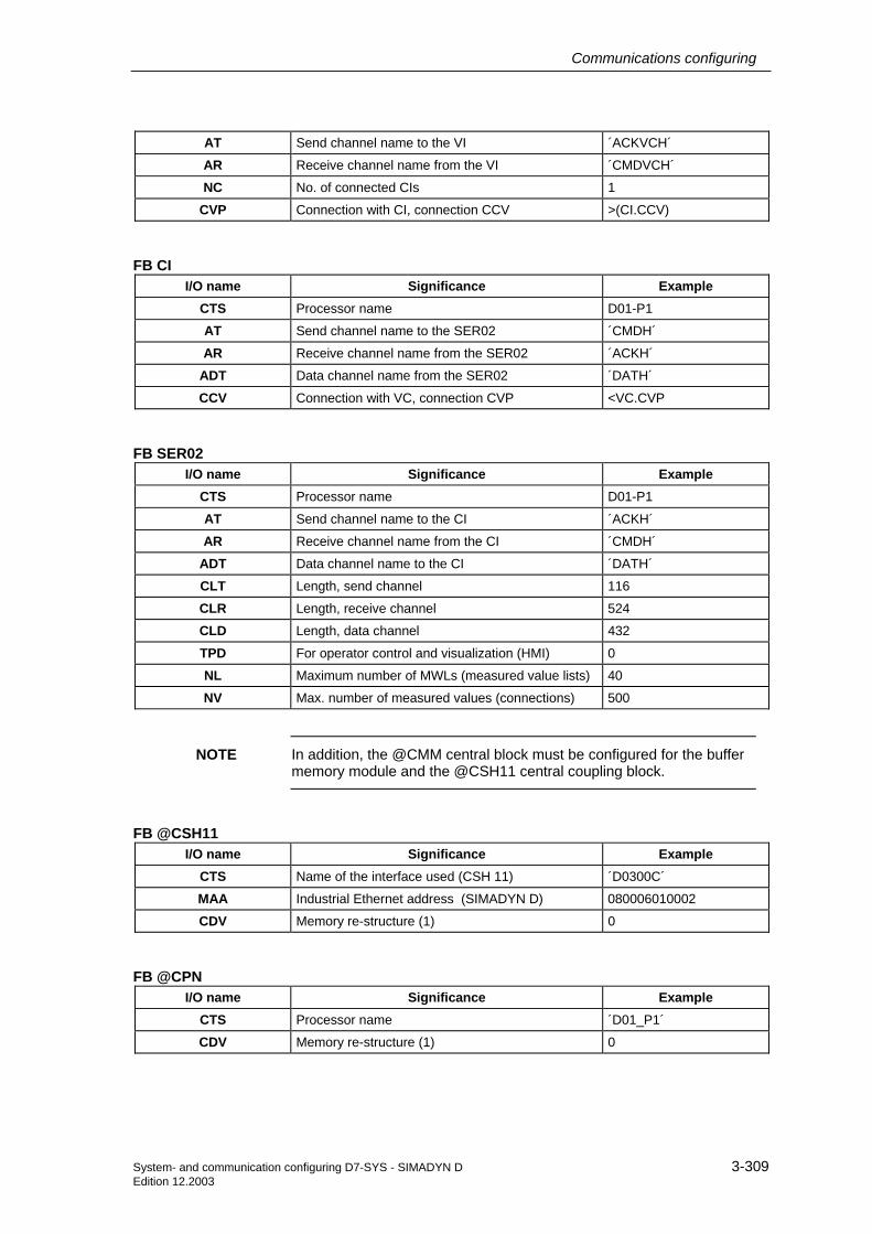
Communications configuring
System- and communication configuring D7-SYS - SIMADYN D 3-309 Edition 12.2003
AT Send channel name to the VI ´ACKVCH´
AR Receive channel name from the VI ´CMDVCH´
NC No. of connected CIs 1
CVP Connection with CI, connection CCV >(CI.CCV)
I/O name Significance Example CTS Processor name D01-P1
AT Send channel name to the SER02 ´CMDH´
AR Receive channel name from the SER02 ´ACKH´
ADT Data channel name from the SER02 ´DATH´
CCV Connection with VC, connection CVP <VC.CVP
I/O name Significance Example CTS Processor name D01-P1
AT Send channel name to the CI ´ACKH´
AR Receive channel name from the CI ´CMDH´
ADT Data channel name to the CI ´DATH´
CLT Length, send channel 116
CLR Length, receive channel 524
CLD Length, data channel 432
TPD For operator control and visualization (HMI) 0
NL Maximum number of MWLs (measured value lists) 40
NV Max. number of measured values (connections) 500
NOTE In addition, the @CMM central block must be configured for the buffer memory module and the @CSH11 central coupling block.
I/O name Significance Example CTS Name of the interface used (CSH 11) ´D0300C´
MAA Industrial Ethernet address (SIMADYN D) 080006010002
CDV Memory re-structure (1) 0
I/O name Significance Example CTS Processor name ´D01_P1´
CDV Memory re-structure (1) 0
FB CI
FB SER02
FB @CSH11
FB @CPN

Communications configuring
3-310 System- and communication configuring D7-SYS - SIMADYN D Edition 12.2003
3.29.2.2 Configuring WinCC
For the particular example, it is sufficient to use a basic WinCC configuring software with several input/output fields.
We will not discuss the WinCC configuring software here. If you require further information refer to the comprehensive WinCC Configuring Manuals. We recommend the Getting Started SIMATIC WinCC Manual for an introduction into configuring WinCC.
3.29.3 Binary events
No additional configuring is required for process value visualization for the binary event technique with WinCC. The selection regarding which bit of a variable initiates which message is realized exclusively in WinCC. The configuring rules to output process variables remain.
In addition to configuring software for the process variables, an ALARM logging configuring software must be generated. We will not discuss the WinCC configuring software here. If you require more detailed information, refer to the comprehensive WinCC Configuring Manuals. We recommend the Getting Started SIMATIC WinCC Manual for an introduction into configuring WinCC.
3.29.4 SIMADYN D messages
3.29.4.1 SIMADYN D configuring software
To output messages from SIMADYN D to WinCC, the WinCC block MM is required in addition to configuring the process value output :
• MM message manager
The blocks are connected as follows :
(Only the relevant connections are described)
I/O name Significance Example CTS Processor name D01_P1
AR Channel name (This is identical with the AT connection of the MSI block)
EMPFKANA
NZ No. of cycles per data transfer 5
NL No. of connected LI blocks 1
MEM Diagnostics triplet 0
TGL Diagnostics triplet 0
Simadyn D configuring software
WinCC configuring software
FB MM

Communications configuring
System- and communication configuring D7-SYS - SIMADYN D 3-311 Edition 12.2003
CVP Connection with LI, connection CCV >LI.CCV
NOTE In addition, the following must be configured: Central message block @MSI, message output block MSI and the message block MERF0.
I/O name Significance Example CMS Message system name MYMELD
CMT Message text (this is not output) ""
NOM No. of messages which can be saved 200
SAV Message buffer, buffered RAM 0
RP Prefix for communication errors 0
MUN Enable for message entries 1
I/O name Significance Example CMS Message system name MYMELD
CTS Coupling module name D01_P1
AT Address parameter EMPFKANA
RP Prefix for overflow messages 0
SNV Output, message number 1
STM Output, message text 0
STC Output, message text constant length 1
SSF Output format 1
EN Enable 1
MUN Enable for message entries 1
FB @MSI
FB MSI

Communications configuring
3-312 System- and communication configuring D7-SYS - SIMADYN D Edition 12.2003
I/O name Significance Example CMS Message system name MYMELD
MT Message type 1
RP Prefix 0
RS1 Suffix, incoming message 10001
RS2 Suffix, outgoing message 00005
EN Message enable 1
IS1 Message trigger 16#0
SM Save message 0
3.29.4.2 WinCC configuring software
In addition to the configuring software for the process variables, an ALARM logging configuring software must be generated. The WinCC configuring software will not be discussed here. If you require information refer to the comprehensive WinCC Configuring Manuals. We recommend the Getting Started SIMATIC WinCC Manual for an introduction into configuring WinCC. The assignment of the SIMADYN D message numbers to the message blocks (RS* connections) to the message numbers, generated by WinCC, can only be identified by the "PMC message no", which is generated from the message numbers of the signal list.
3.29.5 Generating the address book using the CFC editor
To generate the signal list for WinCC, ADRIMP requires the symbol information of the SIMADYN processors. For each CPU, SIMADYN D generates an ASCII file, which contains this information. The file name consists of the subrack names and the CPU number, separated by a "_". ".ADR" is used as extension.
The address book is generated by calling-up the required project chart, and selecting the menu items Options - Settings compilation.... Then mark the Option, Create address book, and enter OK. Call-up the menu items Chart compilation. The address book is now created when compiling. The path of the generated address book is then located via the menu items Options - Report.
The old STRUC G syntax is assumed when generating the address book. The following restrictions must be observed with respect to the CFC syntax :
• Only upper case letters are permitted for the name
• Chart name: Max 6 characters, the first character must be a letter
• Module name: Max 6 characters, the first character must be a letter
FB MERF0
Restrictions

Communications configuring
System- and communication configuring D7-SYS - SIMADYN D 3-313 Edition 12.2003
• Connection name: Max 3 characters, the first character must be a letter
• $ signal name: Max 6 characters, the first character must be a letter
• Scaling range: 0.00001 -- 99999
3.29.6 NML configuring software for CSH11
The configuring tool NML is required to configure the bus for the CSH11 coupling module (with integrated CP1470).
The handling of the NML configuring tool will not be discussed here but if you require further information refer to the NML-CP Manual.
The following configuring software is suitable for establishing a connection between WinCC and SIMADYN D via a CSH11 module using the SINEC H1 protocol (Industrial Ethernet level 4).
Siemens AG SINEC NML V 3.01 Documentation communications 19.02.1998
• Node type: CP 147x
• Node name: roland
• Page: 1 / 1
• Interface type: CP 147x
• Interface name: CP 147x
• Interface profile: CSH11_E4_2000
• Bus address: 080006010002 (SIMADYN D)
• Transport connection.: 6
• Application designation.: 26
• Data basis length: 5888 bytes
• No. of FVTs: 1
1. Transport connection SDCOR1
• Local TSAP-ID: AG_WINCC
• Remote TSAP-ID: WINCC_AG
• Remote bus address: 080006010001 (PC)
Configuring software example
Basic node data
Communication relationships

Communications configuring
3-314 System- and communication configuring D7-SYS - SIMADYN D Edition 12.2003
• Connection set-up: active -> dyn.
• Connection type: E4-connection
• Connection path: Bus
• Profile name: e4_handshake
• No user application relationship assigned
2. Transport connection: SDCOR2
• Local TSAP-ID: WINCC_AG
• Remote TSAP-ID: AG_WINCC
• Remote bus address: 080006010001 (PC)
• Connection set-up: passive <- dyn.
• Connection type: E4-connection
• Connection path: Bus
• Profile name: e4_handshake
• No user application relationship assigned
Using the Transfer utility, it is possible to load the communications description, which was previously generated using the communications configuring software, into the CSH11 module.
3.29.7 Address list import tool ADRIMP
In order that WinCC can interpret the addresses of the SIMADYN D path names, the ADRIMP address list tool is required. The ADRIMP address list tool allows text address lists (TALI) to be listed in the WinCC data base. A precise description is provided in the User Manual Communications Driver SIMADYN D-PMC for WinCC.
3.29.7.1 Prerequisites
A variable definition file must exist, and the SIMADYN D address book must have been previously generated. The variable definition file and the address book must be located in the same path. The generation path can be different, but should also be generated in this path to enhance the software transparency.

Communications configuring
System- and communication configuring D7-SYS - SIMADYN D 3-315 Edition 12.2003
3.29.7.1.1 Generating the variable definition file
The variable definition file is a text file, which must be generated by the user. The variable definition file consists of two defined header lines (1. and 2.), followed by the assignment of symbolic names to the SIMADYN D connection path names. The symbolic names can be freely selected, but should be the same as those used in the WinCC text fields to ensure transparency.
Excerpt from the variable definition file
E.g.: winccvar.txt
1.) [VDM:wincc]
2.) [PN:A000_1,C:\wincc\vardatei]
3.) MOTOR_EIN,ANBIND.CI.CCV
MOTOR_AUS,ANBIND.CI.YTS
3.29.7.1.2 Generating and importing a new signal list
Before generating and importing the signal list, the SIMADYN D PMC driver must be installed in the WinCC configuring software.
• Call-up the WinCC configuring software
• Click-on tag management
• Click-on the menu item "Add new driver"
• Select the SIMADYN D PMC Ethernet.chn
If no WinCC configuring software is started before ADRIMP starts, when importing the signal list, the last configuring software which was used, is used.
• Call-up ADRIMP
• Select the "File" menu item
• Select the "Probi" menu item
• Search for the variable definition file ( e.g.: winvar.txt)
• Define the generation path
• Generate the signal list (e.g.: wincc.txt)
• Exit Probi
Prerequisites
Execution

Communications configuring
3-316 System- and communication configuring D7-SYS - SIMADYN D Edition 12.2003
ADRIMP automatically imports the signal list into the tag management of the appropriate WinCC data administration.
3.29.7.1.3 Importing an existing signal list
• Start WinCC with the required project
• Call-up ADRIMP
• Select the "File" menu item
• Select the "Open" menu item
• Select the signal list (e.g.: wincc.txt)
• Exit ADRIMP
NOTE ADRIMP automatically imports the signal list into the tag management of the appropriate WinCC data administration.
3.29.7.2 Checking the generated tag management in WinCC
Check the imported data, their symbolic names, data formats and SIMADYN D path names:
• Call-up the WinCC configuring software
• Select the variables tag management
• Click-on the logical connection (corresponds to the VDM name)
• Select SIMADYN D PMC ETHERNET
• Select SD- PMC (CP1613-1)
• Select the logical connection names
The logical names and SIMADYN D path names, defined in the variables file, is displayed. The data formats are also displayed. WinCC can now access these variables.
3.29.8 Communications set-up, SIMADYN D-WinCC
3.29.8.1 Connecting cable
The physical connection between SIMADYN D and WinCC is realized via the SIMATIC NET plug-in cable 727-1 for INDUSTRIAL ETHERNET
Note

Communications configuring
System- and communication configuring D7-SYS - SIMADYN D 3-317 Edition 12.2003
3.29.8.2 Activating WinCC
In order to establish communications between SIMADYN D and WinCC, the imported data of the WinCC database must be assigned to the input/output fields of the graphic configuring software. This is realized by selecting the appropriate fields in the Graphics Designer and clicking on the interactive configuration dialog. Each field can be assigned one of the imported variables. After this assignment has been made, the File menu item is selected in the main menu, and the data are saved. Before starting runtime, the connection properties must be set.
• Click-on tag management
• Click-on SIMADYN D PMC
• With the righthand mouse key click-on SD-PMC (CP1613-1)
• Click-on properties
• Click-on the properties, Channel Unit
• Click-on the connection
Enter the Ethernet address for the AG (PLC) (refer to the NML configuring software)
Receive function : Enter a dedicated TSAP-ID (refer to NML Configuring)
Send function : Enter a dedicated TSAP-ID (refer to NML Configuring)
• Confirm with OK
• Select "File" in the Control Center
• Click-on activate
WinCC is now ready to transfer data between SIMADYN D and WinCC
3.29.8.3 Activating SIMADYN D
Power-up the configured subracks. After the subracks have run-up, the connection has been established between SIMADYN D and WinCC. Data is now cyclically transferred between SIMADYN D and WinCC.
In the Control Center

System- and communication configuring D7-SYS - SIMADYN D 4-1Edition 03.2001
4 Changeover from STRUC V4.x to D7-SYS
4.1 Function blocks 4-2
4.2 Adapting specific connection attributes 4-16
4.3 Hardware differences 4-18
4.4 Communications 4-20
4.5 Configuring 4-21
4.6 Configuring, step by step 4-25
4.7 V4.x terminology which is replaced by D7-SYS terminology 4-33
Overview

Changeover from STRUC V4.x to D7-SYS
4-2 System- and communication configuring D7-SYS - SIMADYN DEdition 03.2001
4.1 Function blocks
The following essential features have changed with the introduction ofSIMADYN D7-SYS from STRUC Version 4.x.
• 16-bit function blocks are no longer used
• Assigning names to function blocks and their connections
• Function block names/designations
• DATX attributes have been adapted
• Data types of function blocks have been modified
4.1.1 Assigning names to function block types and connections
The philosophy for assigning names to function block types is that theabbreviations are observed which are allocated by the CFC. The functionblock type designations are oriented to easy to remember rules.
The maximum length of a block type name is 6 characters. The basicname of the function block type is generally three characters long. Anextension can be used for derivatives.
Function block types without extension have the standard data type„Real“ e. g. PWM instead of PWM_R. The logic block types are theexception. These have the standard data type „Bool“ e. g. OR instead ofOR_B.
NOTE The "standard data type" term refers to the "main function" of thefunction block types.
For versions with other data types, this is noted in the "extension" (e. g.AND_W for an AND module type with WORD data type connections).The extension is normally one character long.
Data type BOOL INTEGER DOUBLEINTEGER
REAL SDTIME*
WORD STRING**
GLOBAL**
Extension *_B *_I *_D *_R *_T *_W *_S *_G
* SIMADYN D TIME** At the time of going to print, these data types had still not been used.
Table 4-1 Data type extensions
The byte and double-word data types are an exception. In order that theycan be uniquely identified, they are defined using two characters (refer tothe Section "Changing the data types for function blocks").

Changeover from STRUC V4.x to D7-SYS
System- and communication configuring D7-SYS - SIMADYN D 4-3Edition 03.2001
Data type Byte Double word
Extension *_BY *_DW
Table 4-2 Exceptions of data type extensions
4.1.2 Control blocks
STRUCV.4.x
CFC withD7-SYS
Pre-assignment
*(‘---‘ = 0)
Comment
Control blocksPT10F1 PT1 --- With setting function; new inputs SV,
S; function: Yn+1=SV for S=1
DT10F DT1 --- With setting function; new inputs SV,S; function: Yn+1=SV for S=1
DIF0F DIF --- ---
PC_3F PC QU = 1;QL = 1;
---
INT0F INT --- ---
PIC2F PIC QU = 1;QL = 1;
---
LIM0F LIM QU = 1;QL = 1;
---
DEZ0F DEZ --- ---
DEL0F DEL --- ---
RGE0F RGE --- ---
RGJ0F1 RGJ --- ---
PMW0F PMW --- ---
FUZ001 FUZ_I --- X1..10 as "INT" (previously "N2");Y1..4 as "INT" (previously "N2")
FUZ01F FUZ --- ---
PT10F --- --- Eliminated; replaced by PT1
STC0F --- --- Eliminated; not replaced
* Corresponds to „0“ as pre-assignment of the various parameters of theindividual function blocks.
Table 4-3 Changes in the control blocks

Changeover from STRUC V4.x to D7-SYS
4-4 System- and communication configuring D7-SYS - SIMADYN DEdition 03.2001
4.1.3 Arithmetic blocks
STRUCV.4.x
CFC withD7-SYS
Pre-assignment*(‘---‘ = 0)
Comment
Arithmetic blocksADD2F - --- Eliminated; replaced by ADD
- ADD --- New; generic at the input side
ADD4F - --- Eliminated; replaced by ADD
ADD8F - --- Eliminated; replaced by ADD
ADDI - --- Eliminated; replaced by ADD_I
- ADD_I --- New; generic at the input side
ADDI4 - --- Eliminated; not replaced
SUB0F SUB --- ---
SUBI SUB_I --- ---
MUL0F - --- Eliminated; replaced by MUL
- MUL --- New; generic at the input side
MULI - --- Eliminated; replaced by MUL_I
- MUL_I --- New; generic at the input side
MULI4 - --- Eliminated; not replaced
DIV0F - --- Eliminated
DIV0F1 DIV X2 = 1 ---
DIVI DIV_I X2 = 1 ---
SQR0F SQR --- ---
SII0F SII --- ---
AVA0F AVA --- ---
MAS0F - --- Eliminated; replaced by MAS
- MAS --- New; generic at the input side
MIS0F - --- Eliminated; replaced by MIS
- MIS --- New; generic at the input side
PLI6F PLI10 --- 10 instead of previously 6 points
PLI2F PLI20 --- ---
SIN0F SIN --- ---
ASINF ASIN --- ---
COS0F COS Y = 1 ---
ACOSF ACOS Y = π/2 ---
TAN0F TAN --- ---
ATANF ATAN --- ---
* Corresponds to „0“ as pre-assignment of the various parameters of theindividual function blocks.
Table 4-4 Change in the arithmetic blocks

Changeover from STRUC V4.x to D7-SYS
System- and communication configuring D7-SYS - SIMADYN D 4-5Edition 03.2001
4.1.4 Logic blocks
STRUCV.4.x
CFC with D7-SYS
Pre-assignment
*(‘---‘ = 0)
Comment
Logic blocksAND12 AND12 --- ---
AND2 - --- Eliminated; replaced by AND
- AND I = 1;Q = 1;
New; generic at the input
AND22 - --- Eliminated; replaced by AND_W
- AND_W IS = 65535QS= 65535;
New; generic at the input side
AND4 - --- Eliminated; replaced by AND
AND8 - --- Eliminated; replaced by AND
OR_12 OR_12 --- ---
OR_2 - --- Eliminated; replaced by OR
- OR --- New; generic at the input side
OR_22 - --- Eliminated; replaced by OR_W
- OR_W --- New; generic at the input side
OR_4 - --- Eliminated; replaced by OR
OR_8 - --- Eliminated; replaced by OR
NAN_2 - --- Eliminated; replaced by NAND
- NAND I = 1 New; generic at the input side
NAN4 - --- Eliminated; replaced by NAND
NAN8 - --- Eliminated; replaced by NAND
NOR2 - --- Eliminated; replaced by NOR
- NOR Q = 1 New; generic at the input side
NOR4 - --- Eliminated; replaced by NOR
NOR8 - --- Eliminated; replaced by NOR
XOR2 - --- Eliminated; replaced by XOR
- XOR --- New; generic at the input side
XOR22 - --- Eliminated; replaced by XOR_W
- XOR_W --- New; generic at the input side
NOT NOT Q = 1 ---
NOT02 NOT_W QS = 65535 ---
MFP0F MFP --- ---
PCL0F PCL --- ---
PST0F PST --- ---
PDE0F PDE --- ---
PDF0F PDF --- ---
PIN8 PIN8 --- ---
ETE ETE --- ---

Changeover from STRUC V4.x to D7-SYS
4-6 System- and communication configuring D7-SYS - SIMADYN DEdition 03.2001
STRUCV.4.x
CFC with D7-SYS
Pre-assignment
*(‘---‘ = 0)
Comment
FUI FUI_W --- ---
UDI UDI --- ---
CTR CTR --- ---
NCM NCM_I QE = 1 X1, X2 as "INT" (previously "N2")
NCM0F NCM QE = 1 ---
NSW NSW_I --- X1, X2, Y as "INT" (previously "N2")
NSW04 NSW_D --- X1, X2, Y as "DINT" (previously"N4")
NSW0F NSW --- ---
ANS - --- Eliminated; replaced by ANS_I
- ANS_I --- New; generic at the input side
ANS0F - --- Eliminated; replaced by ANS
- ANS --- New; generic at the input
BSW - --- Unchanged
MUX8 MUX8_I --- X1...X8,CCI, Y as "INT" (previously"N2")
MUX8F MUX8 --- ---
DX_8 DX8_I --- X, Y1...Y8 as "INT" (previously "N2")
DX_8F DX8 --- ---
CNM CNM_I --- X1, X2, Y as "INT" (previously "N2")
CNM04 CNM_D --- X1, X2, Y as "DINT" (previously"N4")
CNM0F CNM --- ---
RSS RSS QN = 1 ---
DFR DFR --- ---
DFRV DFR_W --- ---
RSR RSR QN = 1 ---
SAV SAV_I --- X, Y as "INT" (previously "N2")
SAV01 SAV_B --- ---
SAV04 SAV_D --- X, Y as "DINT" (previously "N4")
SAV0F SAV --- ---
- SAV_TR --- New; 32-bit quantities are saved inthe NOVRAM of a technologymodule T400; Porting the P16-FB-SAVN with the main data type"REAL"
DAT0F DAT --- ---
DLB0F DLB --- ---
BBF0F BF --- ---
SBF0F BF_W --- ---
DTS0F DTS DT = 0.01ms ---
SHD SH --- ---

Changeover from STRUC V4.x to D7-SYS
System- and communication configuring D7-SYS - SIMADYN D 4-7Edition 03.2001
STRUCV.4.x
CFC with D7-SYS
Pre-assignment
*(‘---‘ = 0)
Comment
LVM0F - --- Eliminated; replaced (partially) byLVM
LVM2F LVM --- ---
DUMY NOP1_I --- X, Y as "INT" (previously "N2")
- NOP8_I --- New;
DUMY1 NOP1_B --- ---
- NOP8_B --- New;
DUMY4 NOP1_D --- X, Y as "DINT" (previously "N4")
- NOP8_D --- New;
DUMYF NOP1 --- ---
- NOP8 --- New;
THEN - --- Eliminated; replace (indirect) usingthe sequence group
END - --- Eliminated; replace (indirect) usingthe sequence group
PAS PAS --- ---
PAC0F1 PAC --- ---
PAI PAI --- ---
* Corresponds to „0“ as pre-assignment of the various parameters of theindividual function blocks.
Table 4-5 Changes in the logic blocks

Changeover from STRUC V4.x to D7-SYS
4-8 System- and communication configuring D7-SYS - SIMADYN DEdition 03.2001
4.1.5 Input/output blocks
STRUCV.4.x
CFC with D7-SYS
Pre-assignment
*(‘---‘ = 0)
Comment
Input/output blocks- AENC --- New;
BII8 BII8 --- ---
BIQ8 BIQ8 --- ---
- BIQT --- New;
SBI SBI --- ---
SBQ SBQ --- ---
ADC0F ADC --- ---
AFC0F AFC --- ---
DAC0F DAC --- ---
NAV0F - --- Eliminated; not replaced as only forEM11
NAV0F2 NAV --- ---
NAV0F4 NAVS --- ---
NAV0F5 - --- Eliminated; not replaced (notincluded in the V4 standard library)
NAV0F6 - --- Eliminated; not replaced (notincluded in the V4 standard library)
NDB - --- Eliminated; not replaced
* Corresponds to „0“ as pre-assignment of the various parameters of theindividual function blocks.
Table 4-6 Changes in the input/output blocks
The assignment of the input/output blocks to CPU- and peripheralmodules is shown in the following table.
Input/outputblock
CPU- and peripheral modules
PM5 PM6 T400 IT41 IT42 EA12 EB11AENC x x
BII8 x x x x x x
BIQ8 x x x
BIQT x
SBI x x x x x x
SBQ x x x

Changeover from STRUC V4.x to D7-SYS
System- and communication configuring D7-SYS - SIMADYN D 4-9Edition 03.2001
Input/outputblock
CPU- and peripheral modules
ADC x x x
AFC x
DAC x x x x
NAV x x x
NAVS x x x
Table 4-7 Assignment of the input/output blocks to CPU- and peripheral modules
4.1.6 Communication blocks
STRUCV.4.x
CFC with D7-SYS
Pre-assignment
*(‘---‘ = 0)
Comment
Communication blocks@MSC @MSC NOM = 15 ---
MSI MSI --- ---
MSI2 MSIPRI --- ---
MES MER1 --- ---
MES2 MER_I --- X as "INT" (previously "N2")
MES4 MER_D --- X as "DINT" (previously "N4")
MESF MER --- ---
MESV2T MER16 --- ---
MESV4T - --- Eliminated; replaced by MER16
MESV2 MER0 --- ---
MESV4 - --- Eliminated; replaced by MER0
MED MERF1 --- ---
MED2 MERF_I --- X as "INT" (previously "N2")
MED4 MERF_D --- X as "DINT" (previously "N4")
MEDF MERF --- ---
MEDV2T MERF16 --- ---
MEDV2 MERF0 --- ---
MEDV4 - --- Eliminated; replaced by MERF0
@CTV - --- Eliminated; replaced by CTV
CTV CTV --- Unchanged
@CRV - --- Eliminated; replaced by CRV
CRV CRV --- ---
CCC4 CCC4 --- ---
CDC4 CDC4 --- ---
CTB1 - --- Eliminated; replaced by NOP8_B
CTB2 - --- Eliminated; replaced by NOP8_I

Changeover from STRUC V4.x to D7-SYS
4-10 System- and communication configuring D7-SYS - SIMADYN DEdition 03.2001
STRUCV.4.x
CFC with D7-SYS
Pre-assignment
*(‘---‘ = 0)
Comment
CTB4 - --- Eliminated; replaced by NOP8_D
CTBF - --- Eliminated; replaced by NOP8
@TCI @TCI CHA = 200 ---
@TRI @TRI --- ---
TRCC2 TRCC_I --- X as "INT" (previously "N2")
TRCC4 TRCC_D --- X as "DINT" (previously "N4")
TRCCF TRCC --- ---
@TCP @TCP CHA = 200 ---
TRHI TRHI --- ---
TRP1 TRP_B --- ---
TRP2 TRP_I --- X as "INT" (previously "N2")
TRP4 TRP_D --- X as "DINT" (previously "N4")
TRPF TRP --- ---
@DIS0R - --- Eliminated; replaced by @DIS
@DIS0T - --- Eliminated; replaced by @DIS
- @DIS --- New;
DISA1 - --- Eliminated; replaced by DISA_B
DISA2 - --- Eliminated; replaced by DISA_Iand DISA_W
DISA4 - --- Eliminated; replaced by DISA_D
DISAF - --- Eliminated; replaced by DISA andDISA_T
- DISA_I --- New;
- DISA_B --- New;
- DISA_D --- New;
- DISA --- New;
- DISA_T --- New;
- DISA_W --- New;
DISS1 - --- Eliminated; replaced by DISS_B
DISS2 - --- Eliminated; replaced by DISS_Iand DISS_W
DISS4 - --- Eliminated; replaced by DISS_D
DISSF - --- Eliminated; replaced by DISS andDISS_T
- DISS_I --- New;
- DISS_B --- New;
- DISS_D --- New;
- DISS --- New;
- DISS_T --- New;
- DISS_W --- New;
DISA11 DISA1B --- ---

Changeover from STRUC V4.x to D7-SYS
System- and communication configuring D7-SYS - SIMADYN D 4-11Edition 03.2001
STRUCV.4.x
CFC with D7-SYS
Pre-assignment
*(‘---‘ = 0)
Comment
DISA18 - --- Eliminated; not replaced
DISS11 DISS1B --- ---
DISS18 - --- Eliminated; not replaced
@DPH @DPH UP = 1;PHL = 1;
XWS, YWS, SPS as "INT"(previously "N2");XWL, YWL, SPL as "DINT"(previously "N4")
DPI DPI --- XS, YS as "INT" (previously"N2");XL, YL as "DINT" (previously"N4")
SER SER LT = 242 ---
RTCM RTCM XYR = 97XMO = 1XDA = 1
---
RTC003 RTCABS --- ---
RTC005 RTCREL --- ---
@NMC @NMC --- ---
NRI NRI --- ---
NTC NTC --- ---
NTD NTD --- ---
NSI NSI --- ---
NSL NSL --- ---
@CSL2A @CSL2A MAA = 1;BDR = 3
---
@SYL2A @SYL2A SEL = 1;CNX = 1
---
DIAL2A DIAL2A ST1 = 3;ST2 = 3
---
@CPN @CPN --- ---
@CMM @CMM --- ---
@CEP @CEP --- ---
@CEP22 - --- Eliminated; replaced by @CEP
@CS1 @CS1 --- ---
@CS11 - --- Eliminated; replaced by @CS1
@CS2 @CS2 --- ---
@CS21 - --- Eliminated; replaced by @CS2
@CSH11 @CSH11 --- ---
@CSL2F @CSL2F MAA = 1;BDR = 3
---
@CSL2L @CSL2L MAA = 1;BDR = 3;AST = 1
---
@CSL2D - --- Eliminated; replaced by @CSL2A

Changeover from STRUC V4.x to D7-SYS
4-12 System- and communication configuring D7-SYS - SIMADYN DEdition 03.2001
STRUCV.4.x
CFC with D7-SYS
Pre-assignment
*(‘---‘ = 0)
Comment
@CSD01 @CSD01 BDR = 9600;TWU = 64
---
@CSD02 @CSD02 BDR = 9600;TWU = 64
---
@CSD03 @CSD03 BDR = 9600 ---
@CSD07 @CSD07 BDR = 9600 ---
@CSU @CSU BDR = 9600; ---
- @DRIVE PCF=1PTF=1PEN=1
New;
- PNAME New;
- PLIM MIN=-1.0e38;MAX=1.0e38
New;
- PLIM_I MIN=-32768;MAX=32767
New;
- PLIM_D MIN=-2147483648;MAX=2147483647
New;
- PLIM_T MIN=0.0ms;MAX=1.0e38ms
New;
- PTRANS --- New;
- CBCONF --- New;
- TFAW --- New;
- RFAW --- New;
- SYNCT4 --- New;
- @PEER BDR = 6 New;
- @USS_S BDR = 6;PAR = 1PZD = 2CNX = 10
New;
- @USS_M BDR = 6; New;
* Corresponds to „0“ as pre-assignment of the various parameters of theindividual function blocks.
Table 4-8 Changes in the communication blocks

Changeover from STRUC V4.x to D7-SYS
System- and communication configuring D7-SYS - SIMADYN D 4-13Edition 03.2001
4.1.7 Conversion blocks
STRUCV. 4.x
CFC withD7-SYS
Pre-assignment
*(‘---‘ = 0)
Comment
Conversion blocksBSC B_W --- ---
SBC W_B --- ---
SBW BY_W --- ---
SWB W_BY --- ---
I2NF I_R --- ---
NFI2 R_I --- ---
WDC I_D --- X as "INT (previously "N2");Y as "DINT (previously ("N4")
DWC04 D_I --- X as "DINT (previously "N4");Y as "INT" (previously "N2")
DWR04 - --- Eliminated; not replaced
DWS04 - --- Eliminated; not replaced
N2NF - --- Eliminated; not replaced
N4NF - --- Eliminated; not replaced
NFN2 - --- Eliminated; not replaced
NFN4 - --- Eliminated; not replaced
CBR SWB_W --- ---
CBR04 SWB_DW --- ---
CBRIF SWBI --- ---
CBRQF SWBO --- ---
BNR0F BNR STZ = 2;NF = 1;
---
I4NF D_R --- ---
NFI4 R_D --- ---
* Corresponds to „0“ as pre-assignment of the various parameters of theindividual function blocks.
Table 4-9 Changes in the conversion blocks

Changeover from STRUC V4.x to D7-SYS
4-14 System- and communication configuring D7-SYS - SIMADYN DEdition 03.2001
4.1.8 Diagnostic blocks
STRUCV. 4.x
CFC with D7-SYS
Pre-assignment
*(‘---‘ = 0)
Comment
Diagnostic blocksSTG0F STG --- ---
RFG0F RFG --- ---
SQG0F SQG --- ---
SQGBF SQGB --- ---
USF USF --- ---
ASI ASI --- ---
SYF1 SYF1 --- ---
SYF4 SYF4 --- ---
PNO PNO Y = 1 ---
SSD SSD --- ---
PSL PSL --- ---
- DLED LDN = 1 New;
- EPE --- New;
* Corresponds to „0“ as pre-assignment of the various parameters of theindividual function blocks.
Table 4-10 Changes in the diagnostic blocks
4.1.9 SIMOVERT D block
STRUCV. 4.x
CFC withD7-SYS
Pre-assignment *(‘-
--‘ = 0)
Comment
TRV - --- Eliminated; not replaced
* Corresponds to „0“ as pre-assignment of the various parameters of theindividual function blocks.
Table 4-11 Change in the SIMOVERT D block

Changeover from STRUC V4.x to D7-SYS
System- and communication configuring D7-SYS - SIMADYN D 4-15Edition 03.2001
4.1.10 COROS blocks
STRUCV. 4.x
CFC withD7-SYS
Pre-assignment
*(‘---‘ = 0)
Comment
COROS blocksARD ARD --- ---
ARR ARR --- ---
ARW ARW --- ---
CHC CHC --- ---
CI CI --- ---
ERS1 ERS1 --- ---
RS2 ERS2 --- X, SV, Y as "INT" (previously N2")
FI FI --- ---
FM FM --- ---
LI LI --- ---
MM MM --- ---
RIB RIB --- ---
SER02 SER02 --- ---
SI SI --- ---
SI_02 SI_02 --- X, SV, Y as "INT" (previously "N2")
SI_F SI_F --- ---
VC VC --- ---
VI VI --- ---
VM VM --- ---
BM BM --- ---
TCO TCO --- ---
TRP TRPCOR --- ---
* Corresponds to „0“ as pre-assignment of the various parameters of theindividual function blocks.
Table 4-12 Changes in the COROS blocks
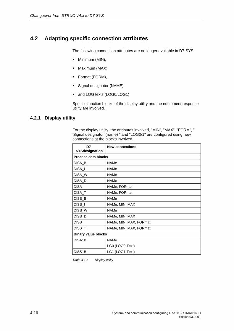
Changeover from STRUC V4.x to D7-SYS
4-16 System- and communication configuring D7-SYS - SIMADYN DEdition 03.2001
4.2 Adapting specific connection attributes
The following connection attributes are no longer available in D7-SYS:
• Minimum (MIN),
• Maximum (MAX),
• Format (FORM),
• Signal designator (NAME)
• and LOG texts (LOG0/LOG1)
Specific function blocks of the display utility and the equipment responseutility are involved.
4.2.1 Display utility
For the display utility, the attributes involved, "MIN", "MAX", "FORM", "'Signal designator' (name) " and "LOG0/1" are configured using newconnections at the blocks involved.
D7-SYSdesignation
New connections
Process data blocksDISA_B NAMe
DISA_I NAMe
DISA_W NAMe
DISA_D NAMe
DISA NAMe, FORmat
DISA_T NAMe, FORmat
DISS_B NAMe
DISS_I NAMe, MIN, MAX
DISS_W NAMe
DISS_D NAMe, MIN, MAX
DISS NAMe, MIN, MAX, FORmat
DISS_T NAMe, MIN, MAX, FORmat
Binary value blocksDISA1B NAMe
LG0 (LOG0-Text)
DISS1B LG1 (LOG1-Text)
Table 4-13 Display utility

Changeover from STRUC V4.x to D7-SYS
System- and communication configuring D7-SYS - SIMADYN D 4-17Edition 03.2001
4.2.2 Equipment response utility
For the equipment response utility, the associated attributes "MIN","MAX" and " 'Signal designator' (name) " are configured using the newfunction blocks PLIM, PLIM_D, PLIM_I, PLIM_T and PNAME.
The DATX attribute is no longer included in D7-SYS. In order to be ableto directly access a connection having a different sampling time using aninput, instead of a DATX attribute, a pseudo comment „@DATX“ must beconfigured.
4.2.3 Changing the data types for function blocks
The comparison between the data types of STRUC V. 4.x and D7-SYS isprovided in the following table:
STRUC V.4.xdata type
(abbreviation)
D7-SYS datatype
(abbreviation)
Designation
B1 BO Bool
I2 I Integer
I4 DI Double-Integer
O2 I The function blocks involved have an integerconnection.
O4 DI The function blocks involved have a doubleinteger connection.
N2 I The function blocks involved have an integerconnection.
N4 DI The function blocks involved have a doubleinteger connection.
NF R Real
V1 BY Byte
V2 W Word
V4 DW Double-Word
NS S String
TF TS SDTime
IK, NK, CR,MR, TR, RR
GV Global
Table 4-14 Data type changes as result of the changeover
Adapting the DATXattributes

Changeover from STRUC V4.x to D7-SYS
4-18 System- and communication configuring D7-SYS - SIMADYN DEdition 03.2001
4.3 Hardware differences
This Chapter describes the hardware differences between STRUC V.4.xand D7-SYS
STRUCV.4.x
CFC withD7-SYS
Comment
SubracksSR4 SR12
SR6 SR6
SR12 SR12
SR24 SR24
- SRD Synonym for T400 master drive configuring
- SRT400
CPU modules- PM5
- PM6
PM16 PM5
PG16 PM5/6 + ITDC
PG26 PM5/6 + ITDC
PS16 PM5/6 + ITDC
PT20 PM5/6 +T41/42
For further information refer to the SIMADYN D"Hardware" Manual
PT20G PM5/6 +IT41/42 +ITDC
For further information refer to the SIMADYN D"Hardware" Manual
PT20M PM5/6 +IT41/42 +MM11/4
For further information refer to the SIMADYN D"Hardware" Manual
PM3 PM5/6
PM4 PM5/6
PT31 PM5/6 + IT41
PT32 PM5/6 + IT41
Expansion modulesIT41 IT41
IT42 IT42
- ITDC
- ITSL
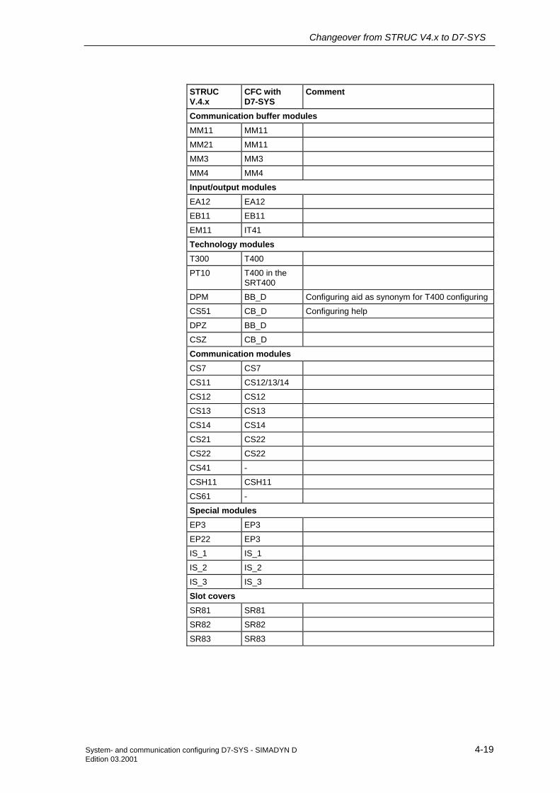
Changeover from STRUC V4.x to D7-SYS
System- and communication configuring D7-SYS - SIMADYN D 4-19Edition 03.2001
STRUCV.4.x
CFC withD7-SYS
Comment
Communication buffer modulesMM11 MM11
MM21 MM11
MM3 MM3
MM4 MM4
Input/output modulesEA12 EA12
EB11 EB11
EM11 IT41
Technology modulesT300 T400
PT10 T400 in theSRT400
DPM BB_D Configuring aid as synonym for T400 configuring
CS51 CB_D Configuring help
DPZ BB_D
CSZ CB_D
Communication modulesCS7 CS7
CS11 CS12/13/14
CS12 CS12
CS13 CS13
CS14 CS14
CS21 CS22
CS22 CS22
CS41 -
CSH11 CSH11
CS61 -
Special modulesEP3 EP3
EP22 EP3
IS_1 IS_1
IS_2 IS_2
IS_3 IS_3
Slot coversSR81 SR81
SR82 SR82
SR83 SR83

Changeover from STRUC V4.x to D7-SYS
4-20 System- and communication configuring D7-SYS - SIMADYN DEdition 03.2001
STRUCV.4.x
CFC withD7-SYS
Comment
Program memory modulesMS5 MS5
- MS51
MS55 MS5
MS41 MS5/MS51
MS45 MS5/MS51
MS300 -
Communication modulesSS4 SS4
SS5 SS5
SS51 SS52
SS52 SS52
Interface sub-modulesSS1 SS1
SS2 SS2
SS31 SS31
Table 4-15 Hardware changes due to the changeover to D7-SYS
4.4 Communications
The following communication possibilities are no longer available inSIMADYN D7-SYS.
STRUC V.4.x designation CommentDUST4 Replacement: SS52, PROFIBUS DP
Replacement: SS5, SINEC L2 FDL
DUST5 Replacement: SS4, USS with VD1
DUST6 and ET100 Replacement: SS52, PROFIBUS DP andET200
Indirect/direct communications Replacement: Process data
Monitor handling Replacement: Service
Equipment response andequipment response on T300
Replacement: Equipment response on T400
Communications to SIMOVIS Not replaced
Redundant serial coupling Not replaced
Selectable network Not replaced
System trace Not replaced
Table 4-16 Changes in the communication possibilities

Changeover from STRUC V4.x to D7-SYS
System- and communication configuring D7-SYS - SIMADYN D 4-21Edition 03.2001
4.5 Configuring
This Chapter describes the differences as far as the configuring isconcerned between STRUC V.4.x and D7-SYS.
4.5.1 Configuring tools
The individual configuring tools which were available in STRUC Version4.x are compared with the appropriate tools in D7-SYS in this Chapter.
Referencepoint
Tool in STRUC V.4.x Tool in D7-SYS
Work station PC with Intel CPU from 486onwards, min. 20 Mbyte mainmemoryCGM- or Postscript printerInternal prommer PP1I orexternal prommer PP1X
PC with Intel CPU from 486onwards, min. 16 Mbyte mainmemoryAny Windows 95/NT-compatible printerPCMCIA slot (generallyincluded in notebooks,available as card for standardunits)
Operatingsystemplatform
SCO Open Desktop V. 3.2xSCO Open Server Release 5
Microsoft Windows 95/NT
Installation Installation program Menu-prompted setup
Administeringproject data
Basic dialog SIMATIC Manager
Configuring thehardware
Master program editor HWConfig
Configuring theopen-loop/closed-loopcontrol
Function package editor CFC
Test/start up FP editor in the IBS G mode CFC in the test mode
List-orientededitors
STRUC L editors For D7-SYS, exclusivelyconfigured using graphic tools.
Table 4-17 Comparison of the configuring tools

Changeover from STRUC V4.x to D7-SYS
4-22 System- and communication configuring D7-SYS - SIMADYN DEdition 03.2001
4.5.2 Object-oriented handling of the configuring tools
The STRUC V4.x configuring tools are always handled depending on theparticular function, i. e. you select a function from the menu (e. g. "Deleteblock") and then the object to be processed (e. g. the block to bedeleted).
The configuring tools of SIMATIC STEP7 are, just like all Windows 95/NTapplications, handled in an object-oriented fashion. You select one orseveral objects (e. g. blocks to be deleted), and then the action which youwish to execute via the menu (e. g. "Edit > Delete block(s)"). Theindividual tools offer diverse possibilities to select objects. The selectioncan either be made via
• menu bar
• context-sensitive pop-up menus
• keyboard commands (hotkeys).
4.5.3 Installation and de-installation
This section describes the installation and de-installation procedure, stepby-step. The sequence is oriented to the "STRUC G installationinstructions" to Version 4.x.
in STRUC V.4.x in D7-SYSOperating systemadaptions
Eliminated
Login as "Superuser" Not necessary, as the installation is possiblewithout any special access authorization.
Installing a driver for aparallel/serial interface
Not necessary, the required drivers are installedwith the automatic hardware identification ofWindows 95/NT.
Installing a driver for a CD-ROM drive
Not necessary, required drivers are automaticallyinstalled with the automatic hardware identificationof Windows 95/NT.
Installing a printer Is realized using the "Printer assistant" fromWindows 95/NT; for further information please referto help under Windows 95/NT under the subject"Printer, setting-up".
Adapting the parameters ofthe operating systemkernel
Not necessary. Ensure that your PC/PG has theminimum hardware requirements, and use thestandard configuration which is set when installingWindows 95/NT.
Configuring a Englishkeyboard
For information, please refer to the help forWindows 95/NT under the subject "Keyboard,layout".
Installing the STRUC Gmaster
Eliminated
Example of object-oriented handling
Installation

Changeover from STRUC V4.x to D7-SYS
System- and communication configuring D7-SYS - SIMADYN D 4-23Edition 03.2001
in STRUC V.4.x in D7-SYSInstalling parallel to olderversions
Not possible.Only one version of STEP7 (and the optionpackages for STEP7) can be installed on a PC.
Loading the data medium Insert the software medium (CD-ROM or floppydisk No. 1) in the drive ...
init - machine initialization ... and start the "Setup" application (in directory"disk1" of the CD-ROM or in the root directory ofthe floppy disk).The "Setup" installation program guides youthrough the installation step-by-step. Pleaseobserve the product information supplied with thedata medium.
print - configuring theprinter
Not necessary, all (graphics-capable) printers areavailable, which you installed underWindows 95/NT, under STEP7 (refer above).
acl - setting accessauthorization
Not required;
lang - setting the language Not necessary. You can change the language ofthe user interface from STEP7 in the SIMATICManager at any time (menu command Extras >Settings, Register side "Language").
burn - programmer gets toknow the operating system
Not necessary. To load memory modules offline inthe CFC, all of the installed PCMCIA slots areavailable.
Installing software for theprogrammer
Not necessary. The required drivers are installedwith the automatic hardware identification functionof Windows 95/NT.Drivers for many commercially available PCMCIAcards are already included in the scope of supply ofWindows 95/NT. Drivers for other devices can beobtained from the appropriate suppliers. The"PCMCIA assistant" of Windows 95/NT will helpyou install the necessary drivers for the PCMCIAslots.For further information, please use the help infosfor Windows 95/NT under the subjects "Hardware,setting-up" and "PCMCIA, activating the supportfor".
Installing the user STRUCG
Not necessary. The installed configuring tools areavailable at this PC for all users.
Table 4-18 Comparison of the installation instructions

Changeover from STRUC V4.x to D7-SYS
4-24 System- and communication configuring D7-SYS - SIMADYN DEdition 03.2001
in STRUC V.4.x in D7-SYSNot possible This is necessary before installing a new product version.
If you wish to install a new product version, without havingdeleted the old version, then you will be appropriatelyinformed at setup.Please follow the instructions in the product informationand the help info to Windows 95/NT under the subject"Software, removing from your computer", in order to de-install the SIMADYN D7-SYS software product.
Table 4-19 De-installation changes
De-installation

Changeover from STRUC V4.x to D7-SYS
System- and communication configuring D7-SYS - SIMADYN D 4-25Edition 03.2001
4.6 Configuring, step by step
The following sections provide an overview for the essential workingsteps under STEP7 which you already know from configuring withSTRUC G V.4.x. Please refer to the appropriate manuals for moredetailed information on the individual working steps, as well as the onlinehelp of the configuring tool. The sequence is oriented to the Chapter"Brief instructions" of the "STRUC G User Manual", Version 4.x.
4.6.1 Administering the project data
This section describes the first steps with the configuring tools.
in STRUC V.4.x in D7-SYSStart STRUC G(basic dialog)
Start STEP 7 (SIMATIC Manager)In the Windows 95/NT desktop:Double click on the "SIMATIC Manager" icon on theWindows 95/NT desktop or call the program Start >Simatic > Step 7 > SIMATIC Manager via theWindows 95/NT task bar.
Create new project Create a new projectIn the SIMATIC Manager:Select the menu command Insert > Program >SIMADYN D program.
Create new masterprogram
Create a new SIMADYN D stationIn the SIMATIC Manager:In the project window, mark the symbol of the project andselect the menu command Insert > Station > SIMADYN Dstation.
Select libraries In the CFC:(refer to the Chapter "Configuring the open-loop/closed-loop control")
Table 4-20 Differences at the start of configuring
4.6.2 Configuring the hardware
in STRUC V.4.x in D7-SYSStart the MP editor Start HWConfig
In the SIMATIC Manager:Double click-on the SIMADYN D station, just created inthe righthand section of the project window, and then onthe "Hardware" symbol.
Create a subrack In HWConfig:Double click in the hardware catalog on one of theSIMADYN D subracks.
Insert the modules In HWConfig:Select the required slot in the subrack table.Double click in the hardware catalog on the module to beinserted.
Insert sub-modules In HWConfig:

Changeover from STRUC V4.x to D7-SYS
4-26 System- and communication configuring D7-SYS - SIMADYN DEdition 03.2001
in STRUC V.4.x in D7-SYSIn the subrack table, select the module slot which is toaccept the sub-module.In the hardware catalog double click on the sub-module tobe inserted.
Define the basicsampling time ofthe CPU modules
In HWConfig:Double click on the CPU module. In the parameterizingdialog window which opens, select the register side "Basicclock cycle".
Define thesampling times ofthe CPU modules
In HWConfig:Double click on the CPU module. In the parameterizingdialog window which opens, select the register side "Cyclictasks".
Define the functionpackage names ofCPU modules
Not required; new CFC charts are simply created in theSIMATIC Manager in the chart container of the particularCPU (refer below).
Define FPconnections($ signals)
Not required; $ signals for communications between CPUsin the subrack no longer have to be centrally defined. Theycan be simply used in CFC at the function blockconnections to be connected.
Define theinterrupts fromCPU modules
In HWConfig:Double click on the CPU module. In the parameterizingdialog window which opens, select the register side"Interrupt tasks".
Define dimensions(unit texts)
Not required; unit texts no longer have to be centrallydefined. They can be simply assigned in CFC whenparameterizing function block connections.
Reference MP In HWConfig you can simultaneously process as manySIMADYN D stations as required. Double click on theSIMATIC Manager on all of the required stations.In HWConfig, you can copy the modules from one stationto another.
Print-out masterprogram
Print-out hardware configurations. In HWConfig:Select the menu command Station > Print.Comment:The print-out is in the form of a list. It includes, amongother things a list of the Order Nos. of all of the configuredmodules and sub-modules.
Compile masterprogram (in thebasic dialog)
Check the hardware configuration for consistencyIn HWConfig:Select the menu command Station > Check consistency.
Exit MP editor Save the hardware configurationIn HWConfig:Select the menu item Station > Save. The individualconfiguring tools of STEP7 (SIMATIC Manager,HWConfig, CFC, ...) can all be simultaneously opened.Thus, you need not exit HWConfig if you wish to continuein the SIMATIC Manager or CFC.
Table 4-21 Differences in the hardware configuration

Changeover from STRUC V4.x to D7-SYS
System- and communication configuring D7-SYS - SIMADYN D 4-27Edition 03.2001
4.6.3 Configuring the open-loop/closed-loop control
in STRUC V.4.x in D7-SYSCreate a newfunction package
Create new CFC charts in the chart container of a CPUIn the SIMATIC Manager:After you have saved the hardware configuration, you willsee, next to the "Hardware" object, symbols in the projectwindow for the CPU modules in the station.Double click on a CPU, and then on the SIMADYN Dprogram in it, and then all of the chart containers in it.Select the menu command Insert > S7 software > CFC.
Start the FP editor Start the CFC editorIn the SIMATIC Manager:Double click on the CFC chart just created.
Import the librariesIn the CFC:A newly created chart container already includes thefunction block types of the FBSLIB standard library.Additional libraries must be explicitly imported into thechart container.Select the menu command Extras > Module types.
Insert functionblocks
In the CFC:Select the menu command View > Catalog to display thefunction block catalog of the CFC.Select the required function block and drag it with thelefthand mouse key depressed into the work area of aCFC chart.
Delete functionblocks
In the CFC:Select the function block(s) to be deleted and then themenu command Edit > Delete.
Copy functionblocks
In the CFC:Select the function block(s) to be copied and then themenu command Edit > Copy.Then select Edit > Insert and place the copied functionblocks at the required position or select the functionblock(s) to be copied and drag them to the requiredposition with the lefthand mouse key and Ctrl keydepressed.You can now copy function blocks from one CFC chart tothe next.
Shift functionblocks
In the CFC:Select the function block(s) to be shifted and shift themouse pointer with the mouse key depressed, to therequired position.Comment:You can also shift function blocks from one CFC chart intoanother chart of the same CPU.

Changeover from STRUC V4.x to D7-SYS
4-28 System- and communication configuring D7-SYS - SIMADYN DEdition 03.2001
in STRUC V.4.x in D7-SYSEdit commentsblock
Enter free comments textIn the CFC:Select the menu command View > Catalog to display thefunction block catalog of the CFC. Select the "Text" entryand, with the mouse key depressed, drag it into the workarea of a CFC chart. Double click on the text field to entertext. With the shift key depressed, click on the text field tochange its size.
Interconnectfunction blocks
In the CFC:Click on the function block output, which is to be thesource for the interconnection. Then click on the inputwhich is the destination of the connection.Comment:The CFC must be in the sheet view.
Connect thefunction blocks tothe margin ($signals, virtualconnections,connections atconnectors, typesCR, IK, MR, NK,RR, TR)
Create interconnections to global operands($ signals, virtual connections, connections at functionblock connections (I/O), data type GLOBAL)In the CFC:Select the function block connection to be connected.Select the menu command Insert > Connection tooperand.
Parameterizefunction blocks
In the CFC:Double click on the function block connection. In the dialogwindow which opens, you can enter a value, commentstext to the connection, scaling factor and units textordouble click on the function block header. You can nowparameterize all the connections (I/O) of this function blockin the register side "Connections" of the dialog windowwhich opens.
Define thesequence in whichthe function blocksare processed
In the CFC:Double click on the function block header. You can nowsee the position of the function block in the sequence inwhich it is executed in the register side "Run-timeproperties" of the dialog window which opens. You cannow remove the function block and insert it at anotherposition in the execution sequence, orselect the menu command Edit > Sequence. You can nowshift the function blocks to other positions in the executionsequence in the window which opens.
Create a run-time group and edit its properties.In the CFC:Select the menu command Edit > Sequence. You cancreate new run-time groups or change thecharacteristics/properties of existing run-time groups in thewindow which opens.

Changeover from STRUC V4.x to D7-SYS
System- and communication configuring D7-SYS - SIMADYN D 4-29Edition 03.2001
in STRUC V.4.x in D7-SYSPrint-out functionpackage
Print-out the CFC chart; in the CFC:Select the menu command Chart > Print to print anindividual chart. Select the menu command Chart >Selective print to print several charts of the chartcontainer.In the SIMATIC Manager:Select the charts to be printed and select the menucommand File > Print.
Change sheet In the CFC:Select the menu command Edit > Go to > Sheet andselect the required sheet.
Change sheet Change between the overview and sheet view of the CFC:In the CFC:Select the menu command View > Overview or View >Sheet view.
Save functionpackage
CFC charts do not have to be saved. Every change whichyou make in the CFC is immediately saved.
Table 4-22 Changes when configuring the open-loop and closed-loop control

Changeover from STRUC V4.x to D7-SYS
4-30 System- and communication configuring D7-SYS - SIMADYN DEdition 03.2001
4.6.4 Compiling and loading the user program
in STRUC V.4.x in D7-SYSCompile the masterprogram (MP-COMP)
Check the hardware configuration for consistency.In the HWConfig:Select the menu command Station > Checkconsistency.
Compile thefunction packages(FP-COMP)
Not necessary as individual step (refer below)
Compile theprocessor program(PN-COMP)
Not necessary as individual step (refer below)
Compile theselected processorprogram(AUTOCOMP)
Compile the user program of a CPUIn the CFC:Place the chart window of the CPU to be compiled in theforeground. Select the menu command Chart > Compile.All of the charts of this CPU are compiled and are thenlinked with the hardware configuration, which has beenchecked for consistency as well as the code libraries toform a runnable user program. In so doing, a map listingof the user program is generated. You will be able toidentify the path names of the map listing from thecompilation protocol.
Create the addressbook (OPTIONSaddress book)
In the CFC:Select the menu command Extras > Settings > Compileand select the "Create address book" option in the dialogwindow which opens.When compiling the user program (menu command Chart> Compile) an address book is automatically generatedfor this CPU. You will be able to identify the path names ofthe address book file from the compilation protocol.
Load the programmodule (PROG -selected PN)
Loading the user program offlineIn the CFC:Select the menu command Target system > Load. Selectthe "Offline" option in the dialog window whichsubsequently opens, and then depress "Load":The compiled user program, and if relevant, theSIMADYN D operating system are loaded into the memorymodule. This memory module is then inserted into thePCMCIA slot of your PC.
Download (PROGdownload)
Loading the user program onlineIn the CFC:Select the Target system > Load menu command. In thedialog window which opens, select the "Online" optionand then depress "Load":The compiled user program, and if relevant theSIMADYN D operating system are loaded into the CPUmemory module via a communications link.
Table 4-23 Compiling and loading the user program

Changeover from STRUC V4.x to D7-SYS
System- and communication configuring D7-SYS - SIMADYN D 4-31Edition 03.2001
4.6.5 Test and start-up
Your software is tested and commissioned in Version 3.1x using the CFCeditor which in this case, has a test mode.
in STRUC V.4.x in D7-SYSStart IBS G (start-upprogram)
Start the CFC editor; in the SIMATIC Manager:Double click on a CFC chart of the CPU to be tested.
Establish an onlineconnection to theCPUs(IBS G online start)
Changeover into the CFC test mode; in CFC:In the creation mode, select the menu command Test >Test mode.Note: This step must be executed for each CPU whichyou wish to test.
Interrupt the onlineconnection to theCPUs(IBS G online stop)
Changeover into the creation mode of the CFC; in theCFC:Select, in the test mode, the menu command Test >Test mode.
Display theconnector valuesonline
In the CFC test mode:Select the connections to be displayed or function blocksand select the menu command Test > Log-onconnections.Select the Test > Monitor menu command to display theactual values of all these connections, logged-on withthis CPU, online.
Create theinterconnectionsonline
In the CFC test mode:Click on the output of the function block which is to bethe source for the interconnection. Then click on theinput which is the destination of the connection.
Delete theinterconnectionsonline
In the CFC test mode:Click on the function block input, which is the end of theinterconnection and then select the menu command Edit> Delete.
Insert the functionblocks online
In the CFC test mode:Select the menu command View > Catalog to displaythe function block catalog of the CFC.Select the required function block and drag it, with themouse key depressed, to the work area of a CFC chart.
Delete the functionblocks online
In the CFC test mode:Remove all interconnections which go from the outputsto the function blocks to be deleted.Select the function block(s) to be deleted and select themenu command Edit > Delete.
Differentiationbetween temporaryand permanentonline changes (IBSG OPTIONS as wellas changing the"permanent" option inthe dialog window"change value").
All online changes are permanently stored in the CFC, i.e. they are saved in the CPU change memory. Evenafter a CPU has been reset, the executed CPU programand the CFC charts, which were changed online,coincide.
Display the errorfields in the "ServiceIBS" tool
System diagnostics: Display the error fields of a CPU.In the CFC:Select the menu command Target system > Modulestatus and then change to the register side "Error fields".

Changeover from STRUC V4.x to D7-SYS
4-32 System- and communication configuring D7-SYS - SIMADYN DEdition 03.2001
in STRUC V.4.x in D7-SYSDisplay the exceptionbuffer in the "ServiceIBS" tool
System diagnostics: Display the exception buffer of aCPU.In the CFC:Select the menu command Target system > Modulestatus and change to the register side "Exceptionbuffer".System diagnostics: Display and change the operatingstatus of a CPU. In the CFC:Select the menu command Target system > Operatingstatus.
Table 4-24 Differences in the test- and start-up phase
The following performance features of STRUC V4.x are not supported inD7-SYS:
• Editing function charts using list-type editors.
• Working with macros.
• Adapting function chart versions to new versions of the function blocklibraries.
• Functions to extract and compile comment texts in the functiondiagrams.
• Undo changes in function charts.
• Tabular displays in the CFC test mode.
Performancefeatures which arenot supported inD7-SYS

Changeover from STRUC V4.x to D7-SYS
System- and communication configuring D7-SYS - SIMADYN D 4-33Edition 03.2001
4.7 V4.x terminology which is replaced by D7-SYS terminology
Terms, which were used in the SIMADYN D environment for Version 4.xare compared in this list, with D7-SYS.
The appropriate explanations can be taken from the glossary.
Terminology from Version4.x
Comparable/new terms Comment
Connector Function block outputOutput
CAUTION, previously in SIMADYN D up to V4.x"Connector" was used which is now designated"connection" (I/O).
Interrupt task Interrupt task
EEPROM Change memory
PSW User program
Module Module
Board ID Module name
Rack Subrack
Rack Subrack
Output connector Function block outputOutput
Input connector Function block inputInput
Initialization, run-up INIT mode
Cyclic operation RUN mode
Processor board, processor CPU module
Processor number CPU number
Daisy chain connector Daisy chain jumper
Connector type Data type
Dialog box Dialog box
Signal module I/O module
Dimensions Units, units text
Configuring mode Create mode
Message system reference Name reference
Promming, loading into thememory module
Offline loading
Download Online loading Loading in the CPU module, loading via acommunications link
Configuring, programming Configuring
Interrupt event Process interrupt
SIMADYN D program Chart container Contrary to an S7- or M7 program, aSIMADYN D program only has a chart container.
Basic dialog SIMATIC Manager
Scaling value Scaling factor
Memory-Card, Memory module
Memory sub-module Memory module

Changeover from STRUC V4.x to D7-SYS
4-34 System- and communication configuring D7-SYS - SIMADYN DEdition 03.2001
Terminology from Version4.x
Comparable/new terms Comment
System function package,@SIMD
System chart
Task Task The sequence in which the user program isprocessed (executed) is defined in the tasks.
Generating, generatingcode
Compiling
Connection Interconnection
Default value Default
Table 4-25 Modified terminology due to the changeover

System- and communication configuring D7-SYS - SIMADYN D 5-1Edition 06.2002
5 Closed-loop thyristor current control
5.1 Overview 5-2
5.2 Function description 5-6
5.3 Commissioning 5-51
5.4 Special features/issues 5-63
5.5 Interfaces to the power electronics 5-65
5.6 Definitions 5-74
5.7 Abbreviations 5-76
5.8 Appendix 5-77
Section overview

Closed-loop thyristor current control
5-2 System- and communication configuring D7-SYS - SIMADYN DEdition 06.2002
5.1 Overview
The documentation for the closed-loop thyristor current control is valid forStep 7 with D7-SYS ≥ version V5.2.0 in conjunction with the CFCprogram.
The closed-loop thyristor current control software can only run inconjunction with the ITDC expansion module.
! WARNING The warning information/instructions in the InstructionManuals/Operating Instructions of the associated thyristor sets must becarefully observed.
The closed-loop thyristor current control is a standard software packagefor closed-loop armature current and field current controls ofsingle (1Q) or four-quadrant (4Q) DC drives.
The following functions are included in the standard software packageCFC Chart “D7-SPTCC”
• Switch-over logic stage
• Closed-loop armature current control
• Closed-loop field current control
• Gating unit
For a 6-pulse, line-commutated drive converter in a B6C or, for two 6-pulse rectifiers in a circulating-current free, anti-parallel, fully-controlledbridge circuit (B6)A(B6)C.
This standard software package exchanges ITDC signals with the6QG2x/6QG3x SITOR sets via the SITOR interface -X7 of the expansionmodule.
These standard software packages should be copied into the user projectand supplemented by the application-specific system data andconnections to the user program.
The gating unit comprises line supply synchronization, actual valuesensing and firing pulse generation and requires a clockwise rotatingfield.
Validity range
Introduction

Closed-loop thyristor current control
System- and communication configuring D7-SYS - SIMADYN D 5-3Edition 06.2002
5.1.1 Hardware configuration
The ITDC converter gating is inserted on a PM5 or PM6 processor andscrewed into place. The modules have a local expansion bus (LE bus) viawhich signals and data are transferred.
~3AC
X01
PM5 / 6
9pin
X5
serialinterface (service)
SITOR inter-face
X7
X6
X5Ext.Vsyn.diagnostics sig.2 analog o/p's
4 dig. outputs 4 dig. inputs 1 incremental encoder
ITDC
SC12 (20pin)
l = 2m
SU11
SC12
SU11
2 AO
4 DO4 DI1 INC
20pin
50pin
20pin
SITOR setor
interface : SE20.2
LEbus
10pin
SC57
COM1/2O perato r con tro l device
l = 5m
M T
SC31.2
SC17.2or
l = 2m
PM 1.ITxx
2.ITxx
LE-I1 LE-I3Interrupt :+ ITxx+ ITDC
ITDCITxx
Fig. 5-1 Hardware configuration
NOTE 2 ITDC modules cannot be used on a processor module. However,combinations with other expansion modules is permitted (e.g. IT41)
The interface: SE20.2 implements the mechanical conversion and theelectrical isolation of the standard SITOR interface from the ITDC to a6QG5x SITOR cabinet or another drive converter.
SITOR sets 6QG2x and 6QG3x differ in the way that thecurrent actual value is sensed, the conditioning of the zero crossoversignals and the phase-to-phase voltages.
If a 6QG2x or 6QG3x SITOR set is used with an optional field devicemodule (excitation option), then the FB FCS is required.
The gating unit has been released for operation with 50 Hz and 60 Hzline supplies (e.g. for PM5); however, it also has automatic frequencyadaptation in the range from 10 to 530 Hz.

Closed-loop thyristor current control
5-4 System- and communication configuring D7-SYS - SIMADYN DEdition 06.2002
The interrupt, depending on the slot on the PM5/6 should be selected inthe "HW Config" software section.The user should make the following settings.
• Interrupt tasks I1: LE bus interrupt L1 (ITDC in the 1st PM slot) orLE bus interrupt L3 (ITDC in the 2nd PM slot)
• Equivalent sampling time 3.3 ms for 50 [Hz] line frequency2.7 ms for 60 [Hz] line frequency
The following settings are made in the standard software package.
• Name: D01_P1 Processor 1 at slot 01• Sampling time T0: 2.0 ms• Name: D02_I1 ITDC module
Properties, ITDC: Addresses:Digital inputs 1 D02_BinSpeed sensing 1 D02_IncEncHW of the closed-loop thyristor current control D02_TCCONTR
5.1.2 Software configuration
The software for the standard closed-loop thyristor current controlcomprises the set from the converter-specific function blocks (FB).
The FBs are programmed in a standard function chart (CFC) for normalapplications of a DC drive.
The closed-loop current control should be integrated in the plant/systemsoftware. Generally, there is a higher-level closed-loop and open-loopspeed control.
CSP 6setp.smth.
FCS 3field current
switch-on
CPC 7dis.pre-ctrl.
SOL 4setpoint
KP TN
EMF 2volt.act.val.EMFgeneration
CAV 5
currentact. value
CPI 8
currentcontroller PC6 9
Firing pulsegeneration
PA6 1
Synchron.
Cyclic Interrupt
⇐
⇐
Faultevaluation
Field current QSF
Switch-on/changeover
QSF
QSF
QSF
CAVEMFPA6PC6FCS
QSF
On command from the control
Setting command
Volt.V/f
Current V/f
Firing pul-se output
Acknowledge
⇐
ITDCFault
⇐Counter
⇐⇐
Speedcontrol
Enable
QSx
Handshake 1-9 = Computation sequence
Fig. 5-2 Overview of the software configuration
HW configuration

Closed-loop thyristor current control
System- and communication configuring D7-SYS - SIMADYN D 5-5Edition 06.2002
Only the most important connections are shown in the diagram.
The FBs should be programmed in a defined sequence.
FBs EMF, CAV and PC6 have a special internal handshake mechanismto acknowledge computation of the FBs.
1. PA6 (firing angle actual generation, 6 pulse)• User-specific FBs for e.g. higher-level speed control loop
in this interrupt sampling time.
2. EMF (voltage actual value sensing)
3. FCS (field current setpoint output), if the option is required.
4. SOL (switch-over logic stage)
5. CAV (current actual value sensing)
6. CSP (current setpoint calculation)
7. CPC (current pre-control in the discontinuous range)
8. CPI (current controller)
9. PC6 (firing angle controller)
FB-PA6 should always be configured at the start of the interrupt-controlled run sequence and FB-PC6 as the last block.Other blocks can also be configured between these blocks depending onthe processor utilization.
All of the converter-specific function blocks should be configured, inaccordance with the run sequence specified above, in an interrupt task I1with alarm source LE1 or LE3.
FB–FCS can also be computed in a cyclic task.
The FB–FCS can be removed from the standard software package if thefield current setpoint is not to be entered via SIMADYN D (for SITOR sets6QG2x, 6QG3x without field device option).
The gating unit computation is started by interrupts in synchronism withthe firing pulse. In steady-state operation (constant firing angle in 50[Hz]line supplies), the interrupts are every 3.3 ms.When converting time-dependent quantities, this time data is required todefine the interrupts (equivalent sampling time in the I1=3.3 ms for 50[Hz]line supplies or 2.7 ms for 60[Hz] line supplies).
The FB–CPC for pre-control in the discontinuous range can be replacedby a polygon characteristic with a characteristic which has beenspecifically plotted.
Run sequence,function blocks
Comment

Closed-loop thyristor current control
5-6 System- and communication configuring D7-SYS - SIMADYN DEdition 06.2002
5.2 Function description
All of the converter-specific function blocks are described in this Section.
The system characteristic quantities are pre-assigned "0" (Default) forexample (e.g. rated voltages, rated currents and armature quantities).
All of the other parameters are pre-assigned non-critical values (e.g. lowcontroller gains, high integral action times).
A list of the parameters to be set is provided in Section 5.3.2.
The blocks have an initialization mode which is executed once after eachsuccessful reset / restart. The values at several connections (Initializationconnections) are only read-in in the initialization mode;changes at one of these initialization connections (Init) are therefore onlyeffective after a reset
Each function block checks the entries for plausibility when specificquantities are configured and when conflicts arise, it outputs a fault ID atfault word QSF.
All of the fault words are collected in the switch-over logic stage FB SOLand are evaluated. The closed-loop thyristor current control cannot beswitched-in if there is a configuring error (refer to Section “SOL, switch-over logic stage”).
5.2.1 PA6, synchronization
Hardware addressMode:V syn ,int./ext. synchr.voltage
Firing pulse numberOffset angle line/synchr.voltage
#Failure line periods up to signal#Stabilizing line periods
Mode:Line handling#Line periods, average
Mode:Rot. field identificationLine frequency [Hz]
GVBOIRDIDIIIIR
ADSYXZPAXDANAZNEPNCMFAMINVFNT
PA6
CTHCTSRDYY6RXASNZG
TAAFPAFI
AVWYIT
YDAXFNZYAZDAQSF
DIDI
BODIRDI
TSRRRRRRII
W
Time value, firing pulse outputTime value, PA6 startLine is ok, enable PC660° value of the line periods [16 MHz]Firing angle actual value [ASG]360° value of the line periods [16 MHz]Time diff. line interrupt [ms]Firing angle, act. value [°]Line filter, phase shift [°]Offset ang. comp. in firing angle act. val.Current duration in the gapsMeasured offset angleMeasured line frequencyDiag.:Synchr. state machineDiag.:Rot. field state machineFault
Fig. 5-3 PA6 represented in the CFC
Parameter defaults
Init connections
Configuring errors

Closed-loop thyristor current control
System- and communication configuring D7-SYS - SIMADYN D 5-7Edition 06.2002
The FB–PA6 is used to continuously synchronize the firing pulses to theline supply for a 6-pulse line-commutated converter.The actual value for the firing pulse position is generated and transferredto the firing pulse controller FB–PC6 in order to evaluate the correctposition of the firing pulses. The firing angle actual value is determinedtaking into account the input filter on the ITDC and the offset angle.
The ITDC generates the interrupt to start FB-PA6 in synchronism to thefiring pulses via the local expansion bus (LE) depending on the internalcounter states.
Program sections of the gating unit which are always executed.
• A line supply analysis, which checks the availability of thesynchronizing voltage and which executes plausibility tests.
• Synchronizing the firing pulses to the synchronizing voltage.
• Determining the offset angle and other line supply quantities.
Synchronization to the line supply (single-phase synchronization) isrealized using a synchronizing voltage derived from the electronics powersupply of the SITOR set (standard) or with the external synchronizationITDC X5 : 5 \ 6.
YDA
pa6.dsf
NEP
FAM
XDA
FNT
[°]
AFI
QSF
NZG
Linesynchr.f(new-old)f(NCM)
Lineswitch-oncounter
NWD
NCM
[°]
Rot. fielddetection
XFN
Erroreval-uation
NAZ
+ +
6Y6R
AFPXAS
Linezerocrossovers
INV
ITDClinetimer
angulardifference
ITDC
filter[°]
RDY
ITDCcurrentduration
YIT
Fig. 5-4 Block diagram of PA6
Function

Closed-loop thyristor current control
5-8 System- and communication configuring D7-SYS - SIMADYN DEdition 06.2002
5.2.1.1 Offset angle
The synchronizing module, which is required for analog gating units isreplaced here by entering an offset angle at input PA6.XDA. Using thisoffset angle, the phase shift between the 6QG2x/6QG3x SITOR setpower connection VL1 and the single-phase synchronizing voltage derivedfrom the electronics power supply line is compensated.
The offset angle PA6.XDA corrects the phase shift between the naturalfiring instant of semiconductor device 1 (α=0°) and the zero crossover ofthe filtered synchronizing voltage (filter on the ITDC). The filter phaseshift is a function of the frequency.
0°Naturalfiring instant, semiconductordevice 1
-30° offset angle AVW
Phase voltage L1
Synchronizing voltage , internal(filtered = phase shift to Vsyn.)
L3
α=0°
360°
AFI
30°
180°
α=150°
Fig. 5-5 Schematic representation of the offset angle in the 50[Hz] line supply
The angle 30[°] is specified as a result of the three-phase system.The FB automatically corrects the existing offset –30[°]. The remainingdeviation should be entered at connection XDA.
e.g. XDA=0.0 ⇒ AVW = -30 [°]XDA=10.0 ⇒ AVW = -20 [°]
The connections of the power section and electronics section of theSITOR set must have the same phase position and the clockwise rotatingin order to ensure perfect functioning of the offset angle determination.(e.g. if the phases are interchanged at the electronics power supply, thisthen incorrectly indicates an incorrect offset angle).
The offset angle between line supply voltage L1 and the filteredsynchronizing voltage, which is to be determined when commissioningthe system, should be entered at input PA6.XDA in degrees(refer to the Section, Determining the offset angle).
Comment

Closed-loop thyristor current control
System- and communication configuring D7-SYS - SIMADYN D 5-9Edition 06.2002
5.2.1.2 Line supply analysis / rotating field detection
The following functions are processed in this program section:
1. The filtered, internal synchronizing voltage (VSYN) is monitored
2. The line supply is checked for a clockwise rotating field
3. The actual offset angle is determined
4. The period duration is checked for stability andthat the rough limits are maintained
The scope of the monitoring calculations to be executed is parameterizedvia connection PA6.INV.
a) If INV=0, the line supply is permanently checked for a clockwiserotating field and the offset angle is determined.
b) If INV=1, a check is made once when starting.
c) If INV=2, there is no monitoring.
START
Pulse inhibit, controller inhibit
RDY = 0
V SYN
Availableand stable
?
orINV=1, and
1st run-through?
edgesV L12 ,V L13
present andstable
?
Clockwise rot.field
detected?
Output,offset angle
YDA = VL1- VL31
Rot. field faultQSF\bit 6
VL12 \ VL13 missingQSF\bit 3,4
Synchron. voltage missing \ erroneous
QSF\bit 1,2
Pulse/controllerenableRDY=1
No
Yes
Yes
No
No
No
Yes
Yes
INV=0 or INV=2
Line
Fig. 5-6 Line supply analysis sequence
Line supplyanalysis sequence

Closed-loop thyristor current control
5-10 System- and communication configuring D7-SYS - SIMADYN DEdition 06.2002
After the line supply is switched-in, it is checked, PA6.NEP. If an attemptis made to enable the closed-loop thyristor current control (SOL.ION=1)before this check has been completed, the bits in the fault ID are set atoutput PA6.QSF. The closed-loop thyristor current control does not gointo operation. The firing angle controller and therefore the pulses remaininhibited until a stable line supply is recognized.
Fault signals inhibit closed-loop thyristor current control operation if theline supply analysis was unsuccessful (refer to Fig. 5-4).
The closed-loop thyristor current control always requires a clockwiserotating field!
If there is a counter-clockwise rotating field, a fault signal is output andthe closed-loop thyristor current control cannot be switched-in.
The clockwise rotating field is determined from the phase shift of the zerocrossovers from L1-L2 (VL12) and L1-L3 (VL13) from the Sitor set.
0°
Phase voltage L1
360°
AFI
0 180°α=150°el
V L1-L3V L1-L2
L1-L2
L1-L3
L3
0
0
0
α=0°el
Fig. 5-7 Zero crossovers of the clockwise rotating field
When determining the phase position between the filtered synchronizingvoltage and the zero crossovers of VL12 and VL13, the actual offset angleis obtained and is output at PA6.YDA in degrees.
XDAPAL
VSYN
VYDAPA .613
.6 ≠−=
When making the check, several line supply periods are evaluated.Output PA6.YDA is a monitoring connection for the commissioningphase.
Comment
Rotating fielddetection

Closed-loop thyristor current control
System- and communication configuring D7-SYS - SIMADYN D 5-11Edition 06.2002
If the external synchronizing voltage source (ITDC-X5:5/6)(mode:PA6.SYX=1) is used, the signals of the zero crossovers of phase-to-phase voltages VL12/VL13 are not available so that the rotating fielddetection should be suppressed (PA6.INV=2).
For the 6QG3x SITOR sets, the zero crossover signals of phase-to-phasevoltages VL12 and VL13 are smoothed and are therefore phase shifted.This is not the case for 6QG2x types. The calculated offset angle shouldthen be appropriately interpreted.
The synchronizing voltage is cyclically monitored and from this value theperiod duration and line frequency determined.
A check is made as to whether the change in its period duration betweentwo consecutive measurements is less than 10 %.
For non-stable line supplies, different line supply handling methods canbe enabled by making the appropriate selection at the PA6.NCMconnector.For example, in the operating mode PA6.NCM=2, an average value ofthe period duration is generated over a parameterizable number ofmeasured values of the period duration. The number of measured valuesused is specified at connection PA6.FAM (refer to the Table).If larger deviations occur more frequently, then the "Synchronizingvoltage erroneous" fault message is output.
All of the frequency-dependent quantities are calculated from the newaverage value of the period duration.
The gating unit calculates an internal offset angle which defines theposition of α=0° with respect to the line supply. The frequency-dependentphase shift of the synchronizing voltage PA6.AFI, filtered through an RCfilter and the offset angle between the line supply and synchronizingvoltage PA6.XDA is included in this quantity.
The line supply frequency is emulated using a 16MHz counter (21 bit)[16MHz] in the line supply value (50Hz = 320000) and is output atPA6.NZG. The value for 60° of the periods is calculated from this valuefor 360°, and is output at PA6.Y6R.
The determined line supply frequency [Hz] is output at PA6.XFN.If the line supply value is not smoothed (PA6.NCM=0), the line supplyfrequency value actual periods can be monitored so that the line supplyfrequency stability can be evaluated.
The actual phase position of the output pulses is compared with areference position (setpoint position), and from this a correction quantityis determined for the pulse position.
6QG2
Line voltage check
Line supplyquantities
Pulsesynchronization

Closed-loop thyristor current control
5-12 System- and communication configuring D7-SYS - SIMADYN DEdition 06.2002
FB–PA6 operates with the pre-set frequency PA6.FNT until the linesupply is connected to the Sitor set.The pre-synchronization, which starts when the line supply is detected,over NEP periods, harmonizes the interrupt frequency to the continuouslymeasured line supply frequency (XFN).If the deviation is <10% of the line supply periods for PA6.NEP timesconsecutively, the firing angle actual value (PA6.XAS) is enabled for theclosed-loop control (FB-PC6) (PA6.RDY).The signal is output as a function of PA6.NEP, but at the earliest after twoline supply periods.
The current conduction duration PA6.YIT in the discontinuous range isdetermined from the zero current signal from the Sitor.Value 1 designates the limit of the non-discontinuous range.
5.2.1.3 Synchronization and pulse generation
The firing pulses for the thyristors for the specified firing angle aregenerated by the firing angle controller FB–PC6.
The firing angle to be set is available at the firing angle controller inputPC6.WAS (= CPI.Y, output of the current controller) in the ASG formatand at the control input PA6.AQL in degrees.
The gating unit synchronizes the phase position of the pulses to the linesupply once every line supply period. Differences which occur arecorrected in the following periods.Connections PA6.NCM, .FAM are especially used when the drive isoperated from weak line supplies.FAM should be set to 0 for operation from “stable” line supplies.
The switch-over logic changes-over from closed-loop controlled operationto open-loop control SOL.ISE. and also selects a torque direction.
Frequencyadaptation
Current conductionduration

Closed-loop thyristor current control
System- and communication configuring D7-SYS - SIMADYN D 5-13Edition 06.2002
PA6. Significance Value\connectionAD Hardware address
SYX Mode: Synchronizing voltage source(normally, phase L1 is used)SYX=0: Internally via the SITOR interface (ITDC-X7:18,34)SYX=1: Externally via connector (ITDC-X5:5)
(Initialization connection/default: 0)
ZPA Firing pulse numberNo. of the active main pulse for the active torque direction.
PC6.ZPA → PA6.ZPA
1…6 XDA Offset angle
of the specified angle corrects the phase shift between the naturalfiring instant of semiconductor device 1 andthe zero crossover of the filtered synchronizing voltage (ITDC)e.g. XDA=0.0 ⇒ AVW = -30 [°] XDA=10.0 ⇒ AVW = -20 [°]Offset angle and natural firing instant (α=0°):
(Default: 0.0)
-180°…+180°
NAZ Number of failed line supply periods of the synchronizing voltageuntil a signal is outputCondition: 0 ≤ PA6.NAZ ≤ 3050, otherwise, QSF\bit 9 = 1
(Initialization connection/default: 8)
NEP Number of line supply periods until the system can be consideredto have stabilized and can be switched-on
Condition: 0 ≤ PA6.NEP ≤ 5000, otherwise, QSF\bit 9 = 1
(Initialization connection/default: 5)
NCM Mode : Line supply handling (also refer to FAM connector)Correction of the counter value of the line supply value (periodduration and phase) before the result is transferred toFB-PC6.0 = the line supply value is not handled1 = refer to NCM=42 = the average value is generated from the last (max.8) linesupply values, the number of which is defined at FAM3= line supply value fluctuation are corrected using the PLLmethod (P controller). The phase difference is only taken intoaccount with 1/FAM.4 = line supply value fluctuations are corrected using the PLLmethod (PI controller). The phase difference is only weighted with1/FAM and the last average with (FAM-1)/FAM.(NCM > 0 is used for weak line supplies or if the synchronizingvoltage is polluted.For single synchronizing voltage disturbances, the best suitablesetting is NCM=4 with FAM=20…40 )
(Default: 0) 0…4 , >4= 0
FAM ≥1…<8
FAM ≥1…≤1000
FAM ≥1…≤1000
FAM For NCM=1: Refer to 4For NCM=2: Number of saved line supply periods to generate theaverage valueFor NCM=3: Factor to reduce a measured phase differenceFor NCM=4: Factor to reduce a measured phase step
(Default: 0)
≥1…<8
≥1…≤1000
≥1…≤1000
I/O PA6

Closed-loop thyristor current control
5-14 System- and communication configuring D7-SYS - SIMADYN DEdition 06.2002
PA6. Significance Value\connectionINV Rotating field detection mode
INV=0 continuous monitoring,INV=1 the rotating field is defined once when startingINV=2 no monitoring
(Initialization connection/default: 0)
FNT Line supply frequency [Hz] for start of synchronization after theline supply voltage is switched-in
Condition: 6 ≤ PA6.FNT ≤ 600, otherwise, QSF\bit 9 = 1
(Initialization connection/default: 50)
CTH Firing pulse output, time value(this value changes in each cycle)
PA6.CTH → PC6.CTH(Default: 0)
CTS Time value at the start of FB-PA6(the value changes in each cycle)
PA6.CTS → PC6.CTS(Default: 0)
RDY Enables the firing angle controller FB-PC6,internal interrupt frequency is harmonized to the line supplyfrequency
PA6.RDY → PC6.EN(Default: 0)
Y6R Counter value = 60° = 1/6 of the line supply periods [16 MHz]NZG / 6
PA6.Y6R → PC6.X6R(Default: 0)
XAS Firing angle actual value [ASG] PA6.XAS → PC6.XAS(Default: 0.0)
NZG Counter value = line frequency (360°) [16 MHz](dependent on NCM)
(Default: 0)50Hz = 32000060Hz = 384000
TA Time difference between the actual and last firing pulse [ms] (Default: 0 ms)AFP Firing angle actual value [°] (Default: 0.0)AFI Phase shift angle of the line supply filter ITDC-HW [°]
( )°∗= 60tan50/farctan AFI (e.g. f = 50Hz ,AFI =60°)
(Default: 0.0)
AVW Offset angular component in the firing angle actual value (refer toXDA)
IAF- 30 XDA AVW °+=
(Default: 0.0)
YIT Current conduction duration in the discontinuous range(YIT <1 = discontinuous current, =1 = continuous current)
PA6.YIT → CPI.XIT(Default: 0.0) >0…1<
YDA Offset angle,This is calculated from the zero crossovers of the synchronizingvoltage and the phase-to-phase line supply voltage. YDA shouldbe equal to XDA.
(Default: 0.0)
XFN Measured line supply frequency [Hz] = f (NZG) (Default: 0.0)
ZYA Diagnostics: Status "Synchronous state machine" (Default: 0)ZDA Diagnostics: Status "Rotating field state machine" (Default: 0.0)QSF Fault PA6.QSF → SOL.QSA
(Default: 16#0000)
Table 5-1 I/O PA6

Closed-loop thyristor current control
System- and communication configuring D7-SYS - SIMADYN D 5-15Edition 06.2002
5.2.2 EMF, voltage - actual value sensing
Hardware addressVolt. sensing [V] Sitor
Motor volt. [V]Normalization
Line voltage [V]Offset frequency [kHz]
Armature resistance, normalizedArmature time constant [ms]
Smoothing time constant f. YEV [ms]Current actual value
Handshake PC6
GVRRRRRRTSTSRBO
ADRRVARVNFAAVXFORATATXCACI
EMF
YEMYUAYURYULYEVYFUYFOTCCACOQSF
RRRRRRR
TSBOW
Calculated EMF (actual value)Output volt. – converterOhmic volt. dropInductive volt. dropCalculated EMF, norm.Frequency V/f conversion [kHz]Offset actual value [kHz]Integr. time voltage actual valueHandshake CAVFault
Fig. 5-8 EMF representation in the CFC
Using the function block FB EMF (Electro Motive Force), the actualoutput voltage Vd is determined and output at EMF.YUA.The output voltage EMF.YUA is normalized using the system parameters(EMF.RRV,.ARV,.NF) or is output as an absolute value.
The rated system voltage (e.g. rated motor voltage) should be specifiedat input EMF.ARV; this is referred to the determined voltage values.
The induced voltage (EMF) of the motor is calculated taking into accountthe ohmic and inductive voltage drop, dependent on current actual valueCAV.YC and is output at EMF.YEM.
The “Typical sensing voltage” of the SITOR set should be entered atinput EMF.RRV. SITOR sets 6QG2x/6QG3x are equipped as standard sothat the V/f converter frequency is increased by 30 kHz at the “Typicalvoltage” (e.g. 6QG2\3 = 1000V).
The power section supply voltage should be entered at input EMF.AAV.
This is calculated from the no-load amplitude π
2313
⋅L
V .
ARV must be > 0.675*AAV, otherwise the “Configuring error” error bit isset at output QSF.
AAV2
3 ARV ⋅π
>
Function
Comments

Closed-loop thyristor current control
5-16 System- and communication configuring D7-SYS - SIMADYN DEdition 06.2002
YFO
YFU
QSF
YUA
YEM
emf.dsf
AAV
PRV
ARV
NF
TA
XFO
RA
XC
ITDC f
x
#
Faulteval.
[kHz][kHz]
[kHz]
YUL
YEV
−YUR
f(#)
f(YUA)
f(XC)
Fig. 5-9 EMF block diagram
For EMF.NF = 1, the normalized values 0 …1 are displayed at outputsENF.YEM, .YUA, .YUR, .YUL.If NF is set to ARV, absolute values = [V] are displayed. When the valueis changed-over, this has an effect on the settings of the controlparameters!
The output voltage Vd of the drive converter is converted into a frequencyusing a voltage-frequency converter and is transferred via the SITORinterface.
rated V 1, 0V , 1-
[kHz] 90 60 30: RangeRRVSitor
V30[kHz]60[kHz]Uf
∗+=∗
→←⋅+=
The number of pulse edges of this signal are converted into a value,integrating over the time period between two firing pulses.
Calculating the drive converter output voltage from the frequency:
−−∗
∗=
]kHz[30
XFO]kHz[60Uf
ARC
NFRRCYUA.EMF
Calculating the induced voltage of the motor EMF from the output voltageand the current actual value:
( ) dtdi
AL AIAR dV
∗−∗−=EMF
V is converted into
YUL YUR YUAEMF.YEM −−=
Normalization
Sensing theterminal voltage Vd

Closed-loop thyristor current control
System- and communication configuring D7-SYS - SIMADYN D 5-17Edition 06.2002
With the ohmic voltage drop:XCRAR ∗=∗∑= armatureI YUR ,whereby RA should
be calculated with the determined armature resistance:
[ ] ( )( )
( )( )CAV NFCAV ARC
EMF ARVEMF NF
RA ∗∗=armature
R
With the inductive voltage drop:
( )1nXCnXCTARA
dtdiLEMF.YUL
−−∗==
The inductive voltage drop is only approximately calculated using thisformula and is therefore not so precise that this value can be used forother calculations.
The EMF value is normalized to the no-load line supply amplitude
ππ
23ˆ
2313 ∗=∗ AAVLV and output.
YEMAAVRRV
23EMF.YEV ∗∗
π=
The EMF is determined with a deadtime by sensing the terminal voltageas the average value between two firing pulses.Thus, current actual value oscillations can occur for an EMF angle pre-control at the current controller.This can be avoided if a greater value than the actual armature timeconstant is configured at input EMF.TA.
The center frequency (60[kHz]) of the V/f converter in the Sitor-converterhas an offset.The offset frequency for Vd=0 V is available at connection EMF.YFO.
XFO - 60[kHz] - YFIEMF.YFO =
NOTE Connection EMF.XFO is an initialization connection and is only validafter a restart \ reset.EMF.XFO should be determined after replacing the SITOR-converterand when commissioning the system.
Instructions are provided in the Section: Voltage sensing calibration.
EMF. Significance Value\connectionAD Hardware addressRRV Sitor rated voltage of the sensing [V].
(e.g. Sitor = 1000[V] PT = 30[kHz] )
Condition: RRV ≥ ARV, otherwise, QSF\bit 14 = 1
(Initialization connection/default: 0.0)
ARV Rated system / motor voltage [V]Condition: RRV ≥ ARV≠ 0, otherwise, QSF\bit 14 = 1
(Initialization connection/default: 0.0)
NF Normalization of the voltage actual value at YUANF= 1 (YUA = normalized value),NF= ARV (YUA , YEM = absolute value)
(Initialization connection/default: 1.0)
Comment
Comment
Calibrationfrequency of the V/fconverter
I/O for EMF

Closed-loop thyristor current control
5-18 System- and communication configuring D7-SYS - SIMADYN DEdition 06.2002
EMF. Significance Value\connectionAAV Line supply voltage [V].
Condition: 3
2ARV AAV π∗⋅≥ , otherwise, QSF\bit14= 1
(Default: 0.0)
XFO Offset frequency of the V/f converter [kHz]Measurement for a drive converter output voltage = 0[V] !Calibration/adjustment: XFO = - YFO !
Condition: -6 kHz ≤XFO≤ 6 kHz, otherwise, QSF\bit 14 = 1
(Initialization connection/default: 0.0)
RA Normalized armature resistance(this should be calculated from the determined value)
(Default: 0.0)
TA Armature time constant [ms] (Default: 0 ms)T Smoothing time for YEV value
(with T=0, smoothing is disabled)(Default: 20 ms)
XC Current actual value (with sign)to calculate the voltage drop of armature quantities
CAV.YC → EMF.XC
ACI Handshake from the PC6 block PC6.ACO → EMF.ACI
YEM Calculated EMF actual valueYULYURYUAYEM −−=
(this value is too inaccurate for other calculations as the valuecalculated for YUL is only approximate!)
(Default: 0.0)
YUA Drive converter output voltage (Default: 0.0)
YUR Ohmic voltage drop across the DC motorXCRAarmatureIR YUR ∗=∗=
(Default: 0.0)
YUL Inductive voltage drop across the DC motor
( )1nXCnXCTARA
dtdiLYUL −−∗==
(Default: 0.0)
YEV EMF value normalized to the no-load line supply amplitude
YEMAAVRRV
23YEV ∗∗
π= (smoothed with time T)
EMF.YEV → SOL.XEV(Default: 0.0)
YFU Frequency of the voltage actual value [kHz] (of the V/fconversion)without correction
(Default: 0.0)
YFO Offset actual value [kHz]XFO - 60[kHz] - YFIYFO =
(Default: 0.0)
TCC Measuring time, voltage measurement (Default: 0 ms)ACO Handshake for CAV block EMF.ACO → CAV.ACI
(Default: 0)QSF Fault EMF.QSF → SOL.QSM
(Default: 16#0000)
Table 5-2 EMF I/O

Closed-loop thyristor current control
System- and communication configuring D7-SYS - SIMADYN D 5-19Edition 06.2002
5.2.3 SOL, switch-over logic
Hardware addressHold-off time [ms]
Pulse cancellation time [ms]Time:M1<>M2
Pulse inhibitMode: V<min, undervolt.
On commandOff command
Only enable M1M1 off commandOnly enable M2
M2 off commandMode:EMF source
Test mode, controlledMode: Current 0, SITOR Y/N=0/1
Operation: Double firingCurrent setpoint 1Current setpoint 2
Threshold MxTime M0 off
Current actual valueCalculated EMF
CAV errorEMF errorPA6 errorPC6 errorFCS error
Error, ext.1Error, ext.2
Mask, HW fault wordMask, YF1 fault wordMask, YF2 fault word
Mask 1, pulse inhibit from YF1Mask 2, pulse inhibit from YF2
Delete YFx, specific bitsAcknowledgement
Hold state for abs. No.
GVTSTSTSBOIBOBOBOBOBOBOBOBOBOBORRRTSRRWWWWWBOBOWWWWWBOBOI
ADTH0TCPTCDIPLUNMIONIOFON1OF1ON2OF2IEFISENZMDZMWC1WC2WCLTM0XCXEVQSCQSMQSAQSPQSSIF1IF2HMHHM1HM2HP1HP2MNEQUIZST
SOL
TAQONQPLQPSQCEQCSQ01Q02QSEQM0QM1QM2QCCYWCYSVZVLZVAZVNZIA
YHWYW1YW2QWYF1YF2QF
TSBOBOBOBOBOBOBOBOBOBOBOWRRIIII
WWW
BOWW
BO
Sampling time, switch-over logicCurrent controller on = enabledPulse inhibit, immediatelyShift to inverter operationEnable controllerSet controllerM1 operationalM2 operationalTest mode, controlled onM0 reached = no setpointM1 requestedM2 requestedControl word PC6Current setpointSetting value, current controllerDiag.:(n-1)statusDiag.:(n) statusDiag.:(n+1)statusDiag.:Interrupt state machineSignal word HW ITDCAlarm word 1Alarm word 2Sum, alarmFault word 1Fault word 2Sum, faults
Fig. 5-10 SOL represented in the CFC
The switch-over logic stage FB–SOL (Switch Over Logic) controls thesequence when switching-in and switching-out the closed-loop thyristorcurrent control for:
• 4Q drives with drive converters in a circulating current-free anti-parallel circuit configuration comprising two fully-controlled three-phase bridge circuits
• 1Q drives with drive converter in a fully-controlled three-phase bridgecircuit configuration.
Function

Closed-loop thyristor current control
5-20 System- and communication configuring D7-SYS - SIMADYN DEdition 06.2002
Additional tasks are executed for four-quadrant drives (4Q).
• A torque direction is selected, and
• The changeover sequence controlled(shift to inverter operation, pulse inhibit, set controller...).
The torque direction is derived from the sign of the complete currentsetpoint (SOL.WC1 + .WC2) from a higher-level control. The followinginter-relationship exists:
• Positive setpoint Torque direction M1
• Negative setpoint Torque direction M2
If a torque direction is not requested, i.e. the setpoint SOL.WC1+SOL.WC2 < SOL.WCL, the "virtual torque direction M0” is reached andoutput SOL.QM0 is set.The outputs QMx are only controlled from the setpoint.
For 1Q drives, torque direction M2 must be inhibited using a permanentoff command SOL.OF2=1.
The switch-over logic stage calculates, from the calculated EMF fromFB–EMF, a pre-control angle with which the current controller is pre-assigned for torque direction reversal. The value is used with theselection: Permanent intervention for each calculation.
The switch-over logic stage executes the following commands for switch-off or changeover:
• Shift to inverter operation (current is reduced) (SOL.QPI).
• The system waits until the zero current signal is received from theSITOR set (SOL.NZM), as soon as the absolute value of the currentactual value (SOL.XC) falls below 3%
• The pulses are deleted and the hold-off time SOL.THO started
• The new torque direction is switched-in after the hold-off timeSOL.THO has expired and the pulse cancellation time SOL.TCP.
The no-current interval when the torque reverses is determined by theI=0 signal and the delay times for the thyristors are between approx. 6.6and 10 ms (this depends on the motor inductance).
The closed-loop thyristor current control is only enabled with
− the on command from the switch-over logic stage at inputSOL.ION,
− the current setpoint SOL.WC1+WC2 > the torque thresholdSOL.WCL, and
− there is no off command or fault condition.
4Q drive
1Q drive

Closed-loop thyristor current control
System- and communication configuring D7-SYS - SIMADYN D 5-21Edition 06.2002
WCL
OF1
TMO
0,0WC1WC2
>
+
01
Shift toINV op.
OFFTime running
M1
M2
XEV
IEF
ON1
ION
IOF
Pulse inhibit
ISE
ON2
NZM
IPL
OF2
Sitor
Internal
Curr. =0eval.
M2ON
OFF
01
M1
ONOFF
01
SOL1.dsf
YWC
YSV
QCE
QM0
QO1
QM1
QM2
QSE
QO2
QPS
QPL
QCC
≥1QON
0,0
Pulse inhibitFault words
enable
enable
Control
//
&
Fig. 5-11 Function diagram SOL control
The inputs SOL.ION, .IOF have a higher priority than the other commandinputs.
The switch-off commands for the torque direction SOL.OF1 \ .OF2 have ahigher priority than the enable signals SOL.ON1 \ ON2 and always resultin the appropriate torque direction being switched-out (disabled).
Switching combinations which are not plausible are either not executed,or result in the closed-loop thyristor current control being switched-out.
If the current actual value only decreases very slowly (e.g. closed-loopfield controls), then it can occur that the “current=zero” signal of theSITOR set oscillates between binary values “0” and “1”. Thesechangeover operations can be suppressed by extending the pulsecancellation time (SOL.TCP). The torque direction is only changed-over ifthe "holding current" is actually fallen below. SOL.TCP = 2 [ms]corresponds to the standard closed-loop thyristor current controloperation for armature supply.
Priorities of theswitch-oncommands
Comment

Closed-loop thyristor current control
5-22 System- and communication configuring D7-SYS - SIMADYN DEdition 06.2002
The controlled test mode is selected with input SOL.ISE = 1. The FB-PC6firing angle controller immediately executes firing angle PC6.AQL. Thetorque direction is derived from the sign of the current setpoint if a torquedirection (SOL.ON1 , .ON2) was not forced.
For the torque changeover, the switch-over logic stage sets the currentcontroller (CPI.SV) to the voltage actual value of the EMF, refer to the no-load amplitude, using the signal SOL.QCS. The EMF can also be set, forthe current controller as EMF pre-control angle (CPI.SVC=1), into the“continuous tracking” mode.
NOTE To enable the pulses, a jumper ITDC -X5:7 \ 10 must be inserted.An “open-circuit” input is interpreted as “external hardware pulseinhibit” and causes the pulses to be immediately inhibited!
SOL. Significance Value\connectionAD Hardware addressTH0 Thyristor hold-off time [ms]
Condition: 0.5 ms ≤ TH0 ≤ 131 ms, otherwise, YW2\bit10=1
(Initialization connection/default: 10 ms)
TCP Thyristor pulse suppression time [ms]
Condition: 0.0 ms ≤ TH0 ≤ 20000 ms, otherwise, YW2\bit10=1
(Initialization connection/default: 2 ms)
TCD Monitoring time for torque change M1 ⇔ M2(inverse > (TCP + THO + TCD) ⇒ fault)
(Default: 50 ms)
IPL Pulse inhibit = 1 is immediately effective!(this is the same as the hardware pulse inhibit ITDC–X5:10.)(At high currents and speed this can result in invertercommutation faults.)
(Default: 0)
UNM Mode: Handling the undervoltage condition (Sitor)UNM=0: Undervoltage signal as alarm (YW1\bit 6)UNM=1: Transition into the status: Pulse inhibitUNM=2: Transition into the status: Pulse inhibit +
total pulse inhibit (HW-ITDC)
(Default: 2)
ION On command for the closed-loop thyristor current control,only if IOF = 0. ION is only level controlled!
A transition from off ⇒ operation is only realized if thesum of the setpoints WC1+WC2 ≥ WCL.
(Default: 0)
IOF Off command for the closed-loop thyristor current controlIOF has priority over all of the other control inputs.
(Default: 0)
ON1 Enable, only torque direction M1,for OF1 = 0 & OF2 = 0
(Default: 0)
OF1 Off command, torque direction M1For QON = 1, only negative setpoints are executed.
(Default: 0)
ON2 Only enables torque direction M2,for OF2 = 0 & OF1 = 0
(Default: 0)
OF2 Off command, torque direction M2For QON = 1, only positive setpoints are executed.
(Default: 0)
Test mode
Changing-over thetorque direction
I/O

Closed-loop thyristor current control
System- and communication configuring D7-SYS - SIMADYN D 5-23Edition 06.2002
SOL. Significance Value\connectionIEF Mode: Use calculated EMF value
(FB EMF present)Use the value at XEV for output at YSV
(Default: 1)
ISE Changes over to the open-loop controlled test mode.The input is only effective for ION=0.Changes at firing angle controller PC6:PC6.AQL=150 [°](firing angle setpoint in the open-loop controlled mode)The setpoints WC1/2 are not relevant during test operation(ISE=1), only the sign! Alternatively, the torque direction to becontrolled can be switched-in (forced) using inputs ON1 andON2
(Default: 0)
NZM Zero current signal from the SITOR set, Y/N=0/1(if NZM=1, no signal is received ⇒ time monitoring TCD sets ahardware fault)
(Default: 0)
DZM Operating signal, double firing from the firing angle control PC6 PC6.DZM → SOL.DZMWC1 Current setpoint 1 YWCWC2WC1 =+ (Default: 0.0)
WC2 Current setpoint 2 (Default: 0.0)WCL Switch-on threshold for the torque direction (absolute value) (Default: 0.01)TM0 Monitoring time for torque direction M0
( ) ( ) 1QM0 TM0 act t & WCLWC2WC1 =⇒⟩≤+
(Default: 2000ms)
XC Current actual value (with sign) CAV.YC → SOL.XCXEV Calculated EMF value (referred to Vdi) for torque reversal and
continuous tracking from FB-CPI)EMF.YEV → SOL.XEV
QSC Fault word from CAV CAV.QSF → SOL.QSCQSM Fault word from EMF EMF.QSF → SOL.QSMQSA Fault word from PA6 PA6.QSF → SOL.QSAQSP Fault word from PC6 PC6.QSF → SOL.QSPQSS Fault word from FCS , if FCS available,
(optional for a 6QG3x SITOR set with option: Excitation)FCS.QSF → SOL.QSS, otherwise = 0.
IF1 Fault, external 1 (appears in YW1\bit 9) (Default: 0)IF2 Fault, external 2 (appears in YW1\bit 12) (Default: 0)HMH Enables the bits for hardware signaling word YHW
and therefore the connection to YW1(Default: 16#FFFF)
HM1 Enables the bits for fault word YF1 (Default: 16#FFFF)HM2 Enables the bits for fault word YF2 (Default: 16#FFFF)HP1 Enables the bits from YF1 for immediate pulse inhibit
WARNING: "Inverter commutation faults" possible!(Default: 16#0020)
HP2 Enables the bits from YF2 for immediate pulse inhibitWARNING: "Inverter commutation faults" possible!
(Default: 16#0040)
MNE Group inhibit, fault words YF1 and YHWdeletes defined bits(refer to the Table under: ∅ = deleted bits)
(Default: 067E)
QUI Acknowledges faults YF1 and YF2The acknowledgment is only realized with ION=0!

Closed-loop thyristor current control
5-24 System- and communication configuring D7-SYS - SIMADYN DEdition 06.2002
SOL. Significance Value\connectionZST Diag.: Stop in the status of the specified number (ZVA)
(The pre-set value (Default value) can only be modified bytrained personnel!)
(Default: 100 )
TA Processing time, switch-over logic stage (Default: 0 ms)QON Closed-loop current control operational
(only enabled if there are no faults and after a switch-oncommand and setpoints WC1+WC2 > WCL > 0.0)
(Default: 0)
QPL Pulse inhibit(the status is displayed at connector ITDC-X5:15 = 0)
(Default: 0)
QPS Shift to inverter operation is executed(The firing angle PC6.AWS becomes active.)
(Default: 0)
QCE Enables the current controller SOL.QCE → CSP.EN(Default: 0)
QCS Sets the current controller FB-CPI, set or track SOL.QCS → CPI.SSOL.QCS → CSP.EN(Default: 0)
Q01 Torque direction M1 operational(setpoint is switched-through to YWC)
SOL.Q01 → CAV.IM1(Default: 0)
Q02 Torque direction M2 operational(setpoint is switched-through to YWC)
SOL.Q02 → CAV.IM2(Default: 0)
QSE Test mode is switched-in (Default: 0)QM0 M0 requested, current setpoint < WCL
= neither M1 nor M2 requested(Default: 0)
QM1 M1 requested (Default: 0)QM2 M2 requested (Default: 0)QCC Control word for FB-PC6 SOL.QCC → PC6.ICC
(Default: 16#0000)YWC Current setpoint SOL.YWC → CSP.WC
(Default: 0.0)YSV Setting value, current controller even when tracking is switched-
inSOL.YSV → CPI.SV (Default:0.0)
ZVL Diag.:(n-1) status (Default: 0)ZVA Diag.:(n) status , control state machine (Default: 0)ZVN Diag.:(n+1) status (Default: 0)ZIA Diag.:Status, interrupt state machine (Default: 0)YHW Signaling word hardware ITDC
(masked by HMH)(Default: 16#0000)
YW1 Alarm word 1 (Default: 16#0000)YW2 Alarm word 2 (Default: 16#0000)QW Sum, alarm
1 bit in YW1 or YW2 = 1(Default: 0)
YF1 Fault word 1 (masked using HM1) (Default: 16#0000)YF2 Fault word 2 (masked using HM2) (Default: 16#0000)QF Sum, fault signal
1 bit in YF1 or YF2 = 1(Default: 0)
Table 5-3 I/O SOL
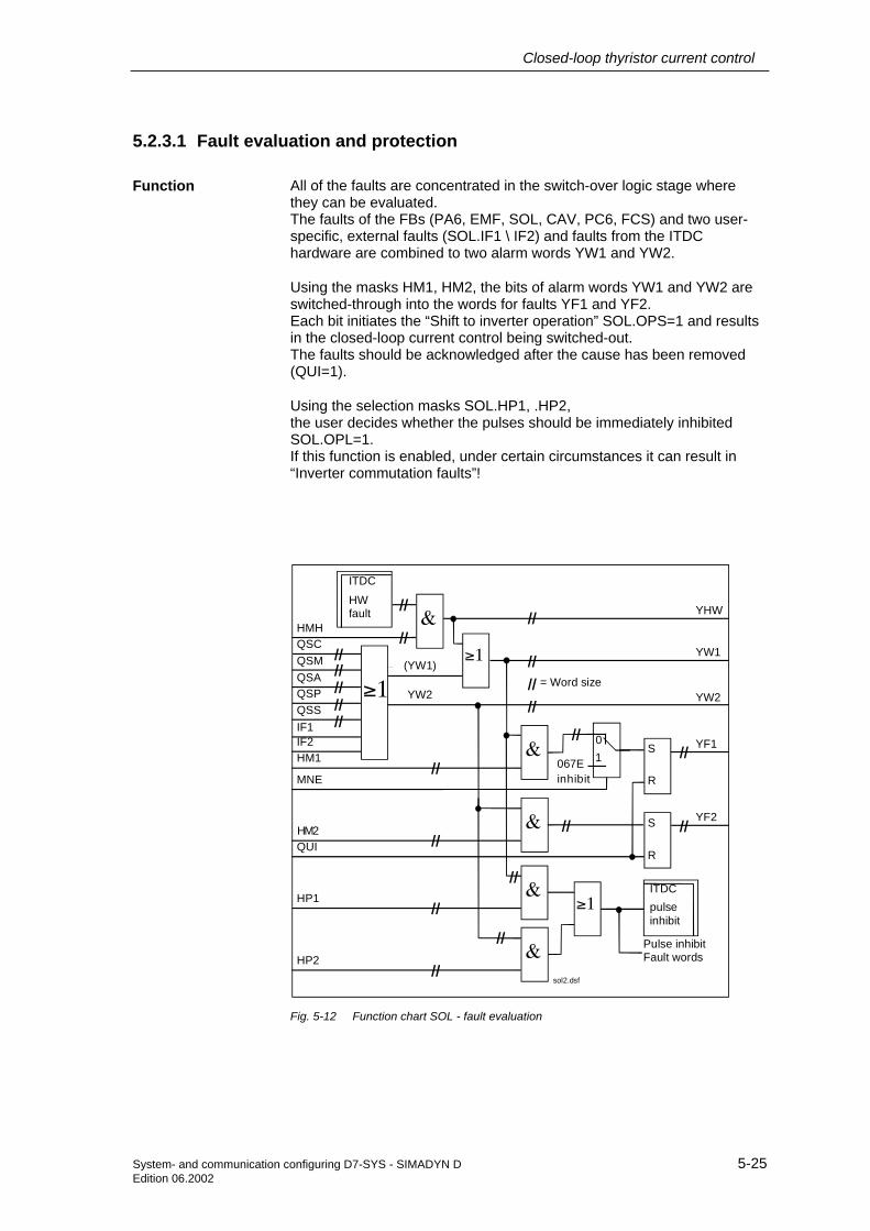
Closed-loop thyristor current control
System- and communication configuring D7-SYS - SIMADYN D 5-25Edition 06.2002
5.2.3.1 Fault evaluation and protection
All of the faults are concentrated in the switch-over logic stage wherethey can be evaluated.The faults of the FBs (PA6, EMF, SOL, CAV, PC6, FCS) and two user-specific, external faults (SOL.IF1 \ IF2) and faults from the ITDChardware are combined to two alarm words YW1 and YW2.
Using the masks HM1, HM2, the bits of alarm words YW1 and YW2 areswitched-through into the words for faults YF1 and YF2.Each bit initiates the “Shift to inverter operation” SOL.OPS=1 and resultsin the closed-loop current control being switched-out.The faults should be acknowledged after the cause has been removed(QUI=1).
Using the selection masks SOL.HP1, .HP2,the user decides whether the pulses should be immediately inhibitedSOL.OPL=1.If this function is enabled, under certain circumstances it can result in“Inverter commutation faults”!
&
≥1
≥1
&
&
&
&
≥1
01
pulseinhibit
S
R
HMH
//
//QSC
QSAQSP
IF1IF2
QSM
QSS
//////////
YW2
//YW1
YHW
YW2
//
//
//
//
//
067E//
////
HM1
MNE
HM2QUI
HP1
HP2
YF1
YF2
HW fault
ITDC
S
R
ITDC
//
// inhibit
//
// = Word size(YW1)
sol2.dsf
Pulse inhibitFault words
//
Fig. 5-12 Function chart SOL - fault evaluation
Function

Closed-loop thyristor current control
5-26 System- and communication configuring D7-SYS - SIMADYN DEdition 06.2002
The user can disable the closed-loop thyristor current control with faultmessage at inputs SOL.IF1, .IF2.
The system can be switched-in again after a fault has occurred after
• Removing the fault
• Acknowledging the fault (signal edge at connection SOL.QUI = 0→ 1)
• Switch-on command (signal transition at connection SOL.ION= 0 → 1)
All of the faults which are present are displayed at outputs SOL.YW1 andYW2; however, they are not saved. Using these outputs, it can bechecked whether a fault has been removed.The faults are only removed from fault words SOL.YF1, .YF2 afteracknowledgment and if they have been removed.
An undervoltage condition, detected by the SITOR set electronics can behandled as configured at input SOL.UNM.
The selection results in different responses to this message:
• UNM=0: Message: Undervoltage as alarm (SOL.YW1\bit 6)
• UNM=1: Transition into the status: Pulse inhibit SW
• UNM=2: Transition into the status: Pulse inhibit SW +total pulse inhibit (HW-ITDC)
The “Temperature monitoring” signal is derived from the fan monitoring ofthe SITOR set and must result in a trip in order to avoid destroying thethyristors as a result of overtemperature.
When the fan runs-up, the SITOR electronics suppresses the monitoringsignal for approx. 10 s. This is the reason that the fan should bepowered-up together with the SITOR set electronics power supply.
The faults, detected by the ITDC hardware are enabled with theSOL.HMH mask, and entered into alarm word SOL.YW1. These maskedbits are output in word SOL.YHW.
External faults
Acknowledgingfault messages
Undervoltage
Temperaturemonitoring
Hardware faults
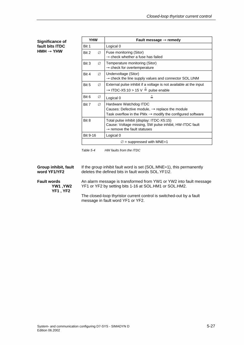
Closed-loop thyristor current control
System- and communication configuring D7-SYS - SIMADYN D 5-27Edition 06.2002
YHW Fault message → remedyBit 1 Logical 0
Bit 2 ∅ Fuse monitoring (Sitor)→ check whether a fuse has failed
Bit 3 ∅ Temperature monitoring (Sitor)→ check for overtemperature
Bit 4 ∅ Undervoltage (Sitor)→ check the line supply values and connector SOL.UNM
Bit 5 ∅ External pulse inhibit if a voltage is not available at the input→ ITDC-X5:10 > 15 V = pulse enable
Bit 6 ∅ Logical 0 =Bit 7 ∅ Hardware Watchdog ITDC
Causes: Defective module, → replace the moduleTask overflow in the PMx → modify the configured software
Bit 8 Total pulse inhibit (display: ITDC-X5:15)Cause: Voltage missing, SW pulse inhibit, HW-ITDC fault→ remove the fault statuses
Bit 9-16 Logical 0
∅ = suppressed with MNE=1
Table 5-4 HW faults from the ITDC
If the group inhibit fault word is set (SOL.MNE=1), this permanentlydeletes the defined bits in fault words SOL.YF1\2.
An alarm message is transformed from YW1 or YW2 into fault messageYF1 or YF2 by setting bits 1-16 at SOL.HM1 or SOL.HM2.
The closed-loop thyristor current control is switched-out by a faultmessage in fault word YF1 or YF2.
Significance offault bits ITDCHMH → YHW
Group inhibit, faultword YF1/YF2
Fault wordsYW1 ,YW2YF1 , YF2

Closed-loop thyristor current control
5-28 System- and communication configuring D7-SYS - SIMADYN DEdition 06.2002
YW1→YF1 Fault message → remedy SourceBit 1 Synchronizing voltage not present / failed
→ check the synchronizing voltage connection (hardware)PA6
Bit 2 ∅ Erroneous synchronizing voltageFrequency step > 10% / periods→ check the synchronizing voltage (hardware)
PA6
Bit 3 ∅ Zero crossovers UL1-2 missing (Sitor)only, if the signal was present once.
→ check the line supply connection and initialization connection PA6.INV
PA6
Bit 4 ∅ Zero crossovers UL1-3 missing (Sitor)only, if the signal was present once.
→ check the line supply connection and initialization connection PA6.INV
PA6
Bit 5 ∅ Rotating field error = no clockwise rotating field of Vsyn.,or both zero crossovers missing.(dependent on the mode: INV)
→ check the line supply connection and initialization connection PA6.INV
PA6
Bit 6 ∅ Undervoltage (Sitor).(dependent on the mode: UNM)
→ check the line supply values and connector SOL.UNM
SOL
Bit 7 ∅ Logical 0
Bit 8 Pulse inhibit, software (.IPL = 1) + hardware command: Total pulse inhibit SOL
Bit 9 Fault, external 1 (SOL.IF1= 1) SOL
Bit 10 ∅ Fuse monitoring (Sitor)→ check for fuse failure
SOL
Bit 11 ∅ Temperature monitoring (Sitor)→ check for overtemperature
SOL
Bit 12 Fault, external 2 (SOL.IF2 = 1) SOL
Bit 13 External pulse inhibit for voltage missing at the input+ hardware command: Total pulse inhibit
→ ITDC-X5:10 > 15 V = enable the pulses
SOL
Bit 14 Excitation current fault(optional for SITOR set 6QG3x with excitation option)
Cause: FCS.FC > 5% and field current actual value < 3% FCS.ARC→ check the field control/connection
FCS
Bit 15 Hardware Watchdog ITDC + hardware command: Total pulse inhibitCauses: Defective module, → replace the moduleTask overflow in the PMx → change the application software
SOL
Bit 16 Hardware command: Total pulse inhibit (ITDC-X5:15)→ remove the fault statuses
SOL
Table 5-5 Fault list SOL.YW1 .YF1
Significance of thefault bits YW1, withHM1 → YF1

Closed-loop thyristor current control
System- and communication configuring D7-SYS - SIMADYN D 5-29Edition 06.2002
YW2→YF2 Fault message → remedy SourceBit 1 Hardware fault of the current actual value sensing (Sitor)
ITDC: Current actual value has not been latched (saved).Cause: V/f conversion frequency not present→ check the current actual value sensing (60 kHz) or ITDC
CAV
Bit 2 Overcurrent M1→ check the system values, connector CAV.CX1 andinitialization connections CAV: RRC, ARC, NF, XFO, AL1
CAV
Bit 3 Overcurrent M2→ check the system values, connector CAV.CX2 andinitialization connections CAV: RRC, ARC, NF, XFO, AL2
CAV
Bit 4 CAV configuring error→ check the initialization connections, CAV:RRC, ARC, AL1, AL2, IAV, XF2, NF, XFO
CAV
Bit 5 Hardware fault: Voltage actual value sensing (Sitor)ITDC: Voltage actual value has not been latched (saved).Cause: V/f conversion frequency not present→ check the voltage actual value sensing (60kHz) or ITDC
EMF
Bit 6 EMF configuring error→ check the initialization connections EMF: RRV, ARV, AAV, XFO
EMF
Bit 7 Pulse position error (PC6)Cause: Erroneous pulse position→ check the line supply values and connectors PC6: DIL, DIZ
PC6
Bit 8 Configuring error→ AAV voltage specified too high (1.35*AAV > 2*ARU)
Bit 9 Fault, zero current signal for M1 ⇔ M2 (NZM=0, Sitor) or Iact >3%→ check the zero current signal from the SITOR interface(only with NZM=0)
SOL
Bit 10 SOL configuring error→ check the initialization connections SOL: TH0, TCP
SOL
Bit 11 SOL block, internal status fault→ check the ITDC hardware
SOL
Bit 12 FCS configuring error→ check the initialization connections FCS: RRC, ARC and FC
FCS
Bit 13 PA6 configuring error→ check the initialization connections PA6: NAZ, NEP, NWD, INV, FNT
PA6
Bit 14 PC6 configuring error→ check the initialization connections PC6: LDU, LDL, AWS, DAG, DAW
PC6
Bit15-16 Logical 0
Table 5-6 Fault list SOL.YW2 .YF2
Significance offault bits YW2, withHM2 → YF2

Closed-loop thyristor current control
5-30 System- and communication configuring D7-SYS - SIMADYN DEdition 06.2002
5.2.4 CAV, current actual value sensing
Hardware addressTyp. current: Sitor
Motor currentNormalization
Offset calibration [kHz]Inv. stability limit, current-dependent
Correction for YAUPos.V. correct. act. value sensingNeg.V. correct. act. value sensing
Max. current M1 (abs. value)Max. current M2 (abs. value)
M1 operationalM2 operational
Handshake EMF
GVRRRRRRRRRRBOBOBO
ADRRCARCNFXFOXF2IAVAL1AL2CX1CX2IM1IM2ACI
CAV
YCYFI
YFOYAUTCCACOQSF
RRRR
TSBOW
Current actual valueFrequency V/f conversion [kHz]Offset actual value [kHz]Inv. stability limit, current-dependentMeasuring time, current act. valueHandshake PC6Fault
Fig. 5-13 CAV represented in the CFC
Using the function block FB–CAV (Current Actual Value), the currentactual value is determined and output at CAV.YC.
The current actual value is either converted into a voltage at a shunt orusing AC current converters in the drive converter and then convertedinto a frequency. This measured frequency is transferred to the ITDCwhere it is measured in the hardware.
The mapping range of the current actual value is±10[V] = 2* rated current, corresponding to ±30[kHz].
The frequency at zero current is 60[kHz].
The average current actual value is determined from the number of pulseedges of the frequency and the time between two firing pulses.
The “Typical DC current” of the drive converter should be entered at inputCAV.RRC.The SITOR sets 6QG2x/6QG3x are equipped as standard, so that thefrequency of the V/f converter is increased by 15 kHz at the typical DCcurrent. At the test socket: Iact is output as 5V.
The rated system/motor current [A] should be specified at inputCAV.ARC. All of the current-dependent thyristor current control quantitiesrefer to this value.
If the current actual value exceeds the limits set at inputs CX1 or CX2,then an "Overcurrent Mx" fault message is output which causes a trip atthe FB SOL (standard), or, depending on what has been configured, onlyan alarm is generated.
If the V/f conversion manifests a gain error, this can be corrected, withinlimits using the data at CAV.AL1 /AL2.The absolute value at CAV.AL1 acts on positive values and the inputCAV.AL2, correspondingly for negative values. The thus corrected actualvalue is provided at CAV.YC.
Function
Limits
Gain error

Closed-loop thyristor current control
System- and communication configuring D7-SYS - SIMADYN D 5-31Edition 06.2002
QSF
CAV.dsf
XFO
YAU[°]
YC
YFOYFI
KP
KP
(#)
M1
M2Bit11
Bit10
CX1
IM1
IM2
CX2
AL1
RRCARCNF
XF2
AL2
(αINV)IAV
Faulteval.
EN >0
ITDC
#
f
f
f
Fig. 5-14 Function chart CAV
The normalized current actual value 0 …1 is displayed at outputCAV.YC with the value CAV.NF = 1.If NF is set to ARV, the absolute value = [A] is displayed. If the value ischanged-over, this has an effect on the setting of the controllerparameters!
Calculating the drive converter output current:
withARCSitorI
15[kHz]60[kHz]If ⋅+=
rated
I 2 1 0I 1- 2-
[kHz] 09756045 30: range Frequency
∗∗=∗∗
→→←←
The current actual value YC is calculated as follows:
−−⋅
∗=
]kHz[15
XFO]kHz[60If
ARC
NFRRCYC
Output YC is signed.
Calibration frequency of the V/f converter. The center frequency (60[kHz])of the V/f converter in the Sitor converter has an offset.The offset frequency for IA= 0 [A] is available at connection CAV.YFO.
XFO - 60[kHz] - YFIYFO =
Normalization

Closed-loop thyristor current control
5-32 System- and communication configuring D7-SYS - SIMADYN DEdition 06.2002
When the closed-loop thyristor current control is switched-out (I=0), thefrequency at YFO corresponds to the offset error of the V/f converter inthe Sitor.The output only indicates values up to 10% of the system current.
NOTE Connection CAV.XFO is an initialization connection and is only validafter a restart \ reset.CAV.XFO should be determined when commissioning the system andafter the SITOR-converter has been replaced.
Instructions are provided in the Section "Current sensing ".
The inverter stability limit is normally permanently specified at FB PC6with a value. If the maximum output voltage is to be used, then the limitmust be adjusted as a function of the current, as the overlap angleincreases as a result of the extended commutation. This means that theinverter stability limit must be reduced in order to avoid “Invertercommutation faults”. A current-dependent inverter stability limit YAU canbe calculated for these special applications.
0 XF2with ,2
1arcsin90180 >∗−−°−°=
IAVXF
ARC
YCYAU
The variations of CAV.XF2 are shown in the diagram.
1.0
1.2
1.4
1.6
1.8
2.0
90°
0.8
0.6
0.4
0.2
0120° 150° 180°
αw
20XF2(%) 10 5 4 3 2 1αw max = f (XF2, YC)|YC| / ARC
XF2 limit
|YC| current actual value (absolute value)
XF2 inductive voltage dropof the converter
IAV correction for YUAαw firing angle end pos.:
Inverter
Fig. 5-15 Dynamic inverter stability limit
The data ≥0.7…1.3≤ at connection CAV.IAV results in an additionalcorrection of the dynamic stability limit.The bandwidth of the correction of CAV.IAV decreases with CAV.XF2 ⇒0.
Line supply changes can be taken into account here.
Negative inverterlimit characteristic

Closed-loop thyristor current control
System- and communication configuring D7-SYS - SIMADYN D 5-33Edition 06.2002
The inverter stability limit calculation is disabled with XF2=0.0.If the function is required, the connections must be established to FB–CPI.CLU and FB–PC6.AWS.
CAV. Significance Value\connection
AD Hardware address
RRC Rated DC current of the SITOR set [A]
Condition: RRC ≥ ARC, otherwise, QSF\bit 12 = 1
(Initialization connection/default: 0.0)
ARC Rated system/motor current [A]
Condition: RRC ≥ ARC ≠ 0, otherwise, QSF\bit 12 = 1
(Initialization connection/default: 0.0)
NF Normalization of the current actual value at YCNF= 1 (YC = normalized value),NF= ARC (YC = absolute value)Condition: NF > 0, otherwise, QSF\bit 12 = 1
(Initialization connection/default: 1.0)
XFO Offset calibration of the V/f conversion frequency [kHz]calibration: XF0 = - YFO! Value measured at I=0 A!
Condition: -6 kHz ≤ XFO ≤ 6 kHz, otherwise, QSF\bit12=1(max. 10% of the rated frequency)
(Initialization connection/default: 0.0)≥-6.0…+6.0≤
XF2 Current-dependent inverter stability limit [1]XF2 corresponds to the “inductive voltage drop” of the converter.XF2=0 % ⇒ stability limit calculation disabled.This intervention is not required for standard applications.
Condition: 0.0 ≤ XF2 ≤ 0.2, otherwise, QSF\bit 12 = 1
(Initialization connection/default: 0.0)≥0.0…0.2≤
IAV Correction for the stability limit [1]Line supply changes can be taken into account here. Thebandwidth always decreases with CAV.XF2 ⇒ 0. Line supplychanges can be taken into account here.
Condition: 0.7 ≤ IAV ≤ 1.3, otherwise, QSF\bit 12 = 1
(Initialization connection/default: 1.0)≥0.7…1.3≤
AL1 Positive correction of the gain, current actual value sensing
Condition: -0.1 ≤ AL1 ≤ 0.1, otherwise, QSF\bit 12 = 1
(Initialization connection/default: 0.0)
AL2 Negative correction of the gain, current actual value sensing
Condition: -0.1 ≤ AL2 ≤ 0.1, otherwise, QSF\bit 12 = 1
(Initialization connection/default: 0.0)
CX1 Max. current for torque direction M1 (absolute value)(observe the normalization!)
(Default: 0.1)
CX2 Max. current for torque direction M2 (absolute value)(observe the normalization!)
(Default: 0.1)
IM1 Torque direction M1 operational ⇒ “+” = CX1 is used. SOL.Q01 → CAV.IM1IM2 Torque direction M2 operational ⇒ “-“ = CX2 is used. SOL.Q02 → CAV.IM2ACI Handshake from the EMF block EMF.ACO → CAV.ACI
YC Current actual value (with sign) CAV.YC → CPI.XC → SOL.XC → EMF.XC(Default: 0.0)
Comment
I/O

Closed-loop thyristor current control
5-34 System- and communication configuring D7-SYS - SIMADYN DEdition 06.2002
CAV. Significance Value\connection
YFI Frequency [kHz] of the V/f conversion of the current actual value(uncorrected value)
(Default: 0.0)
YFO Offset actual value [kHz]XFO - 60[kHz] - YFIYFO =
When the closed-loop thyristor current control is switched-out(I=0), the frequency at YFO corresponds to the offset error of theV/f converter in the Sitor. The output only indicates values up to10% of the system current.
(Default: 0.0)
YAU Limit of the current-dependent inverter stability limit [°]is used, in conjunction:
Interdependencies: Value > 0, if XF2 > 0
(Default: 0.0)CAV.YAU → CPI.CLU → PC6.AWS
TCC Internal measuring time of the current actual value conversion[ms]
(Default: 0 ms)
ACO Handshake for PC6 block CAV.ACO → PC6.ACI(Default: 0)
QSF Fault CAV.QSF → SOL.QSC(Default: 16#0000)
Table 5-7 I/O CAV
5.2.5 CSP, current setpoint calculation
Hardware addressCurrent setpoint (with sign)
Pos. I_max (abs. value)Neg. I_max (abs. value)
Gradient, setpoint smoothingGradient, integrator inhibit
Enable
GVRRRRRBO
ADWCWCUWCLGLIILEN
CSP
YCWYE
QCLQIUQIL
ZVA
RR
BOBOBOINT
Current setpoint, smoothed (abs. value)New-old difference (with sign)Current limit reachedPos. inhibit, integratorNeg. inhibit, integratorDiag.:Status
Fig. 5-16 CSP represented in the CFC
The current setpoint (SOL.YWC) is limited to the absolute value of thecurrent limits CSP.WCU and CSP.WCL.To smooth the setpoint, the difference between setpoint CSP.WC and theCSP.YCW current setpoint, output in the previous cycle, is formed and isoutput at CSP.YE.
The difference, compared with parameter GLI, decides the change ofoutput YCWIf the difference > GLI, then the value of GLI is output.If the difference < GLI, but, > GLI/2, this is limited to GLI/2.If the difference <GLI/2, this is transferred without any correction.The result is added to output YCW with the correct sign.The absolute value of the smoothed and limited current setpoint is outputat CSP.YCW.
Setpointsmoothing

Closed-loop thyristor current control
System- and communication configuring D7-SYS - SIMADYN D 5-35Edition 06.2002
GLI
WCU
WC
WCL
IL
YE
YCW
QIU
QIL
QCL|x|
|x|
|x|
f (GLI, GLI/2)-
>=<
+ IL
- ILTA
+
Fig. 5-17 Function chart CSP
If the difference > +IL or < -IL, the integrator component of the currentsignal is inhibited in the particular direction with signals QIU or QIL.
WCU
0 TA
0,1
0,2
0,3
0,4
0,5
0,6
0,7
7,57,5
55
5510
20
20
15
155 7,5
157,5
7,5GLI
WC
WC
WC
WCU
WC
5
15
t [TA]
YCW
Fig. 5-18 Setpoint smoothing with steps in the setpoint
CSP. Significance Value\connection
AD Hardware address
WC Current setpoint (with sign) SOL.YWC → CSP.WC(Default: 0.0)
WCU Positive current limit (absolute value) (Default: 1.0)
WCL Negative current limit (absolute value) (Default: 1.0)
Setpointsmoothing withsetpoint step WC
I/O

Closed-loop thyristor current control
5-36 System- and communication configuring D7-SYS - SIMADYN DEdition 06.2002
CSP. Significance Value\connection
GLI Gradient for the setpoint smoothingThe actual value from WC is used for the calculation.
(Default: 0.6)
IL Gradient for the integrator inhibit (Default: 0.6)
EN Enable SOL.QCS → CSP.EN(Default: 1)
YCW Smoothed current setpoint (absolute value) CSP.YCW → CPI.WCCSP.YCW → CPC.WC
YE Difference: WC – YCW (with sign)
QCL Pos. or neg. current limit reached
QIU Integrator inhibit of the CPI, positive values CSP.QIU → CPI.ILUQIL Integrator inhibit of the CPI, negative values CSP.QIL → CPI.ILLZVA Diagnostics: Status
Table 5-8 I/O CSP
5.2.6 CPC, current pre-control
Hardware addressCurrent setpoint (abs. value)
Discontinuous current limitStart of the pre-control angle
GVRRR
ADWCVCIALP
CPC
Y R Pre-control angle [ASG]
Fig. 5-19 CSP represented in the CFC
The function block FB CPC (Current Pre-Control) calculates a pre-controlangle for the discontinuous current range from the current setpoint.
The control loop has a different behavior in the discontinuous range thanoutside this range. In the discontinuous range, characteristic Vd / Id nolonger has a linear relationship. The current controller is optimized for thecontinuous current range. This means that either the controller has to beadapted, or the firing angle must be pre-controlled corresponding to thecurrent setpoint.
The FB calculates a pre-control angle according to the following formula:
CAVFBion normalizatcurrent internal
1
411arcsin21
41arcsin21
ALP
−=
−
−∗−
∗∗−∗−
=
NFI
NFI
π
π VCIWC
Y
Function

Closed-loop thyristor current control
System- and communication configuring D7-SYS - SIMADYN D 5-37Edition 06.2002
Pre-control angleY
0WCcurrent setpoint
Discontinuousrange
Non- discontinuousrange
VCI
ALP
max.
min.
Fig. 5-20 Characteristic of the current pre-control
The output CPC.Y must go to zero at the discontinuous limit(PA6.YIT<1), as otherwise the pre-control and the controller wouldoppose each other. This could result in current spikes. The value atCPC.VCI must correspond to the current setpoint at the end of thediscontinuous range.
Significance Value\connection
AD Hardware address
WC Current setpoint (absolute value) CSP.YCW → CPC.WC
VCI Current setpoint at the discontinuous limit,normalized to the motor current CAV.ARC(The discontinuous limit should be determined using PA6.YIT.)This function is switched-out with the value = 0.
(Default: 0.1)0 < VCI <discontinuous limit
ALP Pre-control angle in the discontinuous range [°],start when the current starts to flow
(Default: 25.0)≥25°…30°≤
Y Pre-control angle in the discontinuous range [ASG] CPC.Y → CPI.CPC
Table 5-9 I/O CPC
Note
I/O

Closed-loop thyristor current control
5-38 System- and communication configuring D7-SYS - SIMADYN DEdition 06.2002
5.2.7 CPI, current controller
Hardware addressCurrent setpoint
Pre-control angleCurrent actual value
Inverter stability limit, dynamicInverter control limit
Rectifier control limitSetting value, integrator
Pos. inhibit, integratorNeg. inhibit, integrator
Set. integratorMode: Pre-control
KP gainTN integral action time
Inhibit I componentEnable controller
GVRRRRRRRBOBOBOBORTSBOBO
ADWCCPCXCCLUALUALLSVILUILLSSVCKPTNPCEN
CPI
YYE
YWPYPYI
QUQLTA
YWZSUZSL
RRRRR
BOBOTSNF
RR
Firing angle [ASG]System deviation [1]Pre-control angle [ASG]P componentI componentPos. limit reachedNeg. limit reachedTA: Current controller [ms]Firing angle [degrees]Inverter control limit, RMS [°]Rectifier control limit, RMS [°]
Fig. 5-21 Representation of CPI in the CFC
The function block FB CPI (Current PI Controller) implements aPI controller with a pre-control and setting input.The current controller only uses the absolute value of the currentsetpoint.The I component of the controller can be permanently disabled usingCPI.PC=1.
For large setpoint changes, the integrator can be briefly held usingCPI.ILL or CPI.ILU. This prevents the integrator integrating out of control.The inputs only limit the values in “their direction”.
The firing angle limits are entered at CPI.ALL and CPI.ALU as well as ata higher-level at the firing angle controller PC6.LDU and PC6.LDL.
Internally, the integrator is not limited by the control limits CPI.ALU orCPI.ALL. The integrator value runs up to the format limit (R=+-3,4e38)!
The controller integrator is loaded with the value at input CPI.SV as longas the input CPI.S is set to 1.When the torque direction reverses, the integrator is set by the switch-over logic stage (SOL.QCS) with the calculated EMF actual value andoutput at CPI.YI.
The controller integral component is still limited to this EMF angleCPI.SVC=1.
For analog control systems, this limit replaces the usual pulse inhibit orwobbling at low current actual values.
The EMF actual value, conditioned and normalized by FB SOL isavailable at setting input CPI.SV. The integrator is set during changeoverwith the control command from SOL.QCS at input CPI.S.
Function
Comment
Set I component
Pre-control angle

Closed-loop thyristor current control
System- and communication configuring D7-SYS - SIMADYN D 5-39Edition 06.2002
KP
KP CPC
TN
f(SV)
min f(X)
f(X)
01
-
WC
ILUILL
XC
S
SV
PC Hold
Inhibit, pos.Inhibit, neg.
EN
++
SVC
ALL
CLU
ALU
YEYP
QUYQI
YI
YWP
ZSL
ZSU
0,0
TN
+
Set
Fig. 5-22 Function chart CPI
EN = enable controller X = irrelevant
S = setting the integrator with the setting value
SVC = pre-control mode
0 X X Controller inhibitOutputs Y,YE,YWP,YP,YI are set to 0
1 0 0 Normal functionYIYPY +=
1 0 1 With continuous tracking (correction)0 YI,YWPYPY =+=
1 1 0 Setting modeSV YI, YIYPY =+=
1 1 1 Setting mode with continuous trackingSV YI, YWPYIYPY =++=
Table 5-10 Behavior of the control inputs

Closed-loop thyristor current control
5-40 System- and communication configuring D7-SYS - SIMADYN DEdition 06.2002
When selecting the mode “Pre-control and continuous tracking”CPI.SVC=1, the current controller converts this actual value into a pre-control angle CPI.YWP = “EMF angle” and this is added to controlleroutput CPI.Y.
The pre-control angle CPI.YWP is limited to the effective limits CPI.ZSUand ZSL.
( ) ( )
-1SV if -1
1 SV if 1
1 SV1- SVarcsin2
SVfYWP
<⇒=
+>⇒+=
≥≤⇒∗==
The actual value of the EMF sensing FB EMF must be calibrated asprecisely as possible. The EMF has a deadtime.The continuous tracking is only possible with separate sensing due to theaverage value generation of the current sensing in the Sitor.
Input CPI.CLU allows the current-dependent limiting of the invertercontrol limit to be additionally influenced.
The function of the dynamic inverter stability limit is programmed in FBCAV and requires the connection (CAV.YAU → CPI.CLU)
The lower value of CPI.ALU and CPI.CLU acts as limiting for the invertercontrol limit and is the dynamic effective control limit, output at CPI.ZSU.
Tracking
Dynamicinverter controllimit

Closed-loop thyristor current control
System- and communication configuring D7-SYS - SIMADYN D 5-41Edition 06.2002
CPI. Significance Value\connectionAD Hardware addressWC Current setpoint (absolute value) CSP.YCW → CPI.WCCPC Pre-control angle in the discontinuous range CPC.Y → CPI.CPC
(Default: -0.333333= 30[ASG] )
XC Current actual value (with sign) CAV.YC → CPI.XCCLU Limit of the current-dependent inverter stability limit [°],
if this function is not required, CLU=ALU should be set to 150 [°].CAV.YAU → CPI.CLU(Default: 150.0)
ALU Inverter control limit of the firing angle [°]the minimum of CLU and ALU is used
(Initialization connection/default: 150.0)
ALL Rectifier control limit of the firing angle [°] (Initialization connection/default: 30.0)
SV Setting value for torque reversal or continuous tracking(only active for S = 1)(SV corresponds to the torque reversal of the motor EMF)
SOL.YSV → CPI.SV>-1…+1<
ILU Integrator inhibit, positive direction CSP.QIU → CPI.ILU(Default: 0)
ILL Integrator inhibit, negative direction CSP.QIL → CPI.ILL(Default: 0)
S Sets the integrator with the value SV SOL.QCS → CPI.SSVC Mode: Pre-control of the CPI (Default: 0)KP Proportional gain [1] (Default: 0.01)TN Integral action time [ms] (Default: 10000 ms)PC Inhibits integrator component
(with PC=1 ⇒ integrator is deleted)(Default: 0)
EN Controller enable(with EN=0, all Yxx are immediately set to zero)
SOL.QCE → CPI.EN
Y Firing angle [ASG] CPI.Y → PC6.WAS(Default: 0.0)
YE System deviation XCWCYE −= (Default: 0.0)
YWP Pre-control angle [ASG] (Default: 0.0)YP P component (Default: 0.0)YI I component (Default: 0.0)QU Controller at its positive limit (M1) (Default: 0)QL Controller at its negative limit (M2) (Default: 0)TA Sampling time: Current controller (configured) (Default: 0 ms)YW Firing angle [°]
(same as Y, only in another format)(Default: 0.0)
ZSU Inverter control limit, effective [°](internally used limit f (ALU,CLU) is displayed)
(Default: 0.0)
ZSL Rectifier control limit, effective [°](ALL limit is displayed)
(Default: 0.0)
Table 5-11 I/O CPI
I/O

Closed-loop thyristor current control
5-42 System- and communication configuring D7-SYS - SIMADYN DEdition 06.2002
5.2.8 PC6, firing angle controller
Hardware addressMode:7kHz/long pulsesInverter control limit [°]
Rectifier control limit [°]Main pulse length [ms]
Second pulse length [ms]Time value firing pulse output
Time value PA6 startEnable firing angle controller
60° value [16 MHz]Firing angle actual value [ASG]
Firing angle setpoint [ASG]Test: Firing angle setpoint [°]
Shift to inv. op.: Firing angle setpoint [°]>Rect./TA max. angular change [°]
>Inv./TA max. angular change [°]Tolerance pulse pos. from pos. error
#Error DILControl word
Mode, double firingHandshake CAV
GVBORRTSTSDIDIBODIRRRRRRRDIWBOBO
ADLPDLDULDLLMPLFPCTHCTSENX6RXASWASAQLAWSDAGDAWDILDIZICCDZACI
PC6
TCPACAZPAZZAZLAZXA
WAFYEADZMZAHACOQSF
TSRIIII
RR
BOW
BOW
Process. time all FB [ms]Process. time FB[°]Firing pulse No. 1...6Firing pulse adjust. No.Diag.:Status "double firing state mach."Diag.:Pulse pos. error generation, statusAngular setpointSystem deviation, firing angle controllerDouble firing activeControl HW ITDCHandshake EMFFault
Fig. 5-23 PC6 represented in the CFC
The PC6 function block (Pulse Controller 6-pulse) is used to implement a"Dead-beat" controller and the firing pulse generation for a 6-pulse line-commutated converter for a fully-controlled bridge B6C or two fully-controlled bridges in a circulating-current free, anti-parallel circuitconfiguration B6(A)B6(C).
Various firing angle setpoints are used, depending on the operatingmode, entered from the switch-over logic stage.
• Closed-loop controlled operation (SOL.ISE = 0)
• Shift to inverter operation (SOL.QPI = 1)
• Open-loop controlled operation (SOL.ISE = 1 = testoperation)
The firing pulses for the thyristors of the SITOR set are generated on theITDC according to the specifications of FB PC6.The firing pulses are output as 7[kHz] pulse chains (standard) or as longpulses.
FB PC6 is always calculated as the last block in an interrupt task insynchronism with the firing pulses.
Function

Closed-loop thyristor current control
System- and communication configuring D7-SYS - SIMADYN D 5-43Edition 06.2002
ITDChard-ware
01 0
1 01
Fault evaluation
Pulsepositionmonitor-ing
Doublefiring
Control
WAF
YEA
ZPA
(ZXA)
QSF
(ZLA)DZM
ZAH
PC6.dsf
AQL
AWS
XAS
EN
ICC
DZ
WAS [ASG] -> [°]
[ASG] -> [°]
DAG DAW
BIT3
/ TE
S T
B IT 8
/ s h
ift to
inv.
op. 90° -
LDL LDU
AUS
Release
DIL
DIZ
Control word HW
Fig. 5-24 Function diagram of PC6
It is possible to evaluate the accuracy of the gating unit by monitoring thepulse positions (this can be parameterized).
The firing angle setpoint is switched-over from the switch-over logic stage(command word SOL.QCC → PC6.ICC).Corresponding to the selected mode, the inputsPC6.WAS (closed-loop controlled operation)PC6.AQL (test operation, open-loop controlled)PC6.AWS (shift to inverter operation)are used as manipulated variable to generate the firing pulses.
In the “Closed-loop/open-loop controlled operation” modes, the firingangle setpoints are fed through a ramp-function generator.Separate change time constants are entered in the form of gradients forthe two directions. The gradients PC6.DAG specify the max. angularchange / sampling cycle ([°] / [TA]) in the direction of rectifier operation,PC6.DAW the max. angular change / sampling cycle towards inverteroperation.
The ramp-function generator is de-activated in the “Shift to inverteroperation” mode.
The absolute limiting of the control limits are always active usingparametersPC6.LDU (inverter control limit) andPC6.LDL (rectifier control limit)!
The limits, configured at current controller FB CPI.ALU, .ALL only act, ifthey have lower values than those at the absolute limits at FB PC6.
Firing anglesetpoint
Control limits fortherectifier andinverter

Closed-loop thyristor current control
5-44 System- and communication configuring D7-SYS - SIMADYN DEdition 06.2002
During operation the pulse position monitoring checks the differencebetween the firing angle setpoint and the actual value.If the absolute value of the deviation exceeds the limit [°], entered at inputPC6.DIL, the counter is incremented at each calculation. If the counterstatus reaches the value at PC6.DIZ, the difference was too high anddirectly initiates a hardware pulse inhibit and a fault message.
A line supply frequency change is mapped in the internal counter valueson the ITDC and is immediately taken into account, after transfer, in thefiring angle actual value PC6.XAS and in the 60° value of the line supplyperiods PC6.X6R (refer to the Section: Synchronization and pulsegeneration).
The counter status "60° of the line supply periods" is used to shift thefiring pulses.
The firing pulse waveform should be selected using input PC6.LPD andinternally changes-over the ITDC. The “7 kHz pulse chain” waveform(PC6.LDP = 0) is selected as default, as the thyristor gating in the Sitorsets is only designed for pulse chains. If long pulses are output to a Sitor,this destroys the gating!Long pulses should only be set for special thyristor gating circuits.
The length of the main pulse should be parameterized at input PC6.LMP(1.1 [ms]) and the second pulse at input PC6.LFP (1.1 [ms]). The pulselength may not exceed 45[°el], and must be adapted to the linefrequency. We recommend that the length data are kept the same..
Operation: Double firing results in a special status of the closed-loopthyristor current control and is selected using the command PC6.DZ = 1.For fault-free operation, output PC6.DZM should be set to 1. Whenactivated at SOL.DZM, the output voltage goes to zero and a free-wheeling branch is therefore enabled. The first firing pulse following theenable is continuously output with the associated firing pulse of the samephase. This means that the DC circuit is de-coupled from the line supply(refer to Section: Definitions).
The double firing command is directly executed. It can be switched-in atany time in rectifier operation; this is not possible in inverter operation.The command can be withdrawn at any time.
After the double firing has been de-activated, the firing pulses aregenerated again in synchronism with the line supply.The current controller and therefore the firing angle setpoint are tracked(corrected) by the switch-over logic stage during double firing operation.
If the controller or pulses have not been enabled (EN=0), the setpoint(WAF) is pre-assigned the constant firing angle of 90°.
Pulse positionmonitoring
Synchronizing
Pulse waveform
Double firing
Note
Enable

Closed-loop thyristor current control
System- and communication configuring D7-SYS - SIMADYN D 5-45Edition 06.2002
PC6. Significance Value\connectionAD Hardware addressLDP Selects the firing pulse waveform:
LDP = 0: 7kHz pulse chains,LDP = 1: Long pulses7kHz is required for all Sitor converters.
(Initialization connection/default: 0)
LDU Absolute inverter (INV) control limit [°]Condition: 90 ≤ PC6.LDU ≤ 180, otherwise, QSF\bit 9 =1(180° is a theoretical value. The free-wheeling, pulsecancellation time and the overlapping due to the commutationmust be taken into account.)
(Initialization connection/default: 150)
LDL Absolute rectifier (RECT.) control limit [°]Condition: 0 ≤ PC6.LDL ≤ 90, otherwise, QSF\bit 9 = 1(The limit should lie symmetrically around 90° to the invertercontrol limit.)
(Initialization connection/default: 30)
LMP Main pulse length [ms]Conversion into degrees according the line frequency f:
ms05.0LMP][360310[Hz] f[ms] LMP][ LMP ≥⇒°∗−
∗∗=°
If the configured value is lower, LMP is limited to 50 µs.
(Default: 1.1ms) < 45[°] el.
LFP Second pulse length [ms]We recommend that the value = LMP should be kept.(handled according to connection LMP)
(Default: 1.1ms) < 45[°] el.
CTH Firing pulse output, time value(the value changes in each cycle)
PA6.CTH → PC6.CTH
CTS Time value at the start of FB-PA6(the value changes in each cycle)
PA6.CTS → PC6.CTS
EN Firing angle controller enable is realized,if Vsyn. and line supply = ok
PA6.RDY → PC6.EN
X6R Numerical value = 60° of the line supply period [16 MHz](50 Hz = 320000[1])
PA6.Y6R → PC6.X6R 221
XAS Firing angle actual value [ASG] PA6.XAS → PC6.XAS-1...0...+1
WAS Firing angle setpoint [ASG] CPI.Y → PC6.WASAQL Test operation: Firing angle setpoint [°]
Input limited with LDL ≤ AQL ≤ LDUThe transferred firing angle is directly executed!Enter small changes in order to avoid overcurrents.
(Default: 150)
AWS Shift to INV operation: Firing angle setpoint [°]This angle becomes setpoint with signal SOL.QPI. The currentcontroller is disabled.
Condition: 90 ≤ AWS ≤ 180, otherwise, QSF\bit 9 = 1
(Initialization connection/default: 150)
DAG Max. angular change/sampling cycle in the direction of rectifieroperation
Condition: 0 ≤ PC6.DAG ≤ 180, otherwise, QSF\bit 9 = 1
(Initialization connection/default: 60)
DAW Max. angular change/sampling cycle in the direction of inverteroperation
Condition: 0 ≤ PC6.DAW ≤ 180, otherwise, QSF\bit 9 = 1
(Initialization connection/default: 150)
I/O

Closed-loop thyristor current control
5-46 System- and communication configuring D7-SYS - SIMADYN DEdition 06.2002
PC6. Significance Value\connectionDIL Pulse position tolerance [°]
Limit for the setpoint-actual value difference of the firing angle.(Default: 1.0)
DIZ Number of permissible continuous limit violations, DIL (Default: 3)ICC Control word
(assignment, refer below)SOL.QCC → PC6.ICC
DZ Operation: Double firingFor DZ=1, a firing pulse pair of a phase is constantly output inthe constellation 1-4, 2-5, 3-6 or 4-1, 5-2, 6-3.
(Default: 0)
ACI Handshake from the CAV block CAV.ACO → PC6.ACI
TCP Processing time of all FBs [ms] (Default: 0 ms)ACA Processing time in [°]
(incl. 100 µs safety tolerance)(Default: 0.0)
ZPA Number of the firing pulse PC6.ZPA → PA6.ZPA(Default: 0)
ZZA Diag.: Firing pulse adjustment number(indicates the change of the number, only for changes > 60°.)
(Default: 0)-3...0...+4
ZLA Diag.: Status "Double firing state machine" (Default: 0)ZXA Diag.: Status "Pulse position fault generation" (Default: 0)WAF Firing angle setpoint α [°]
(max. changes/TA are limited by DAG or DAW.)(Default: 0.0)
YEA System deviation, firing angle controller (Default: 0.0)
DZM Operation: Double firing active PC6.DZM → SOL.DZM(Default: 0)
ZAH Control word, hardware(assignment, refer below)
(Default: 16#0000)
ACO Handshake for EMF block PC6.ACO → EMF.ACI(Default: 0)
QSF Fault word PC6.QSF → SOL.QSP(Default: 16#0000)
Fig. 5-25 I/O PC6

Closed-loop thyristor current control
System- and communication configuring D7-SYS - SIMADYN D 5-47Edition 06.2002
Displays the control of the hardware register on the ITDC module
ZAH Signal/messageBit 1 Torque direction M1 enabled
Bit 2 Torque direction M2 enabled
Bit 3 Second pulses enabled
Bit 4 Operation: Double firing enabled
Bit 5 Pulse inhibit for undervoltage (refer to selection, SOL.UNM)
Bit 6 Pulse chains activated
Bit 7 Logical 0
Bit 8 Int./ext. synchronizing voltage (0/1),(relay changeover of the inputs)
Bit 9-16 Logical 0
Table 5-12 Control word, hardware (ZAH)
5.2.9 FCS, field current setpoint output
Hardware addressRated field rectifier current
Field currentNormalization
Field onField off
Field setpointEnable
Option: Field presentEstablish field
GVRRRBOBORBOBOSD
ADRRCARCNFIONIOFFCENIET
FCS
QONQEO
TAZVAQSF
BOBOTF
IW
On command, delayedOn command, instantaneousSampling time, configured [ms]Diag.:StatusFault
Fig. 5-26 FCS represented in CFC
The function block FB FCS (Field Current Setpoint) is used to enter thefield current setpoint for the excitation option and implements thesequence control to switch-in and switch-out the motor excitation and theclosed-loop current control as well as a fault logic.
The switch-over logic stage to the system software is moved from FBSOL to FB FCS in order to take into account field built-up in the control.
The optional field device for the Sitor set is a single-phase "half-controlled" rectifier (B2HKFU) and requires a field current setpointPC6.FC ≥ 0. Negative values are set to zero and result in a configuringerror.
Control word,hardware (ZAH)
Function

Closed-loop thyristor current control
5-48 System- and communication configuring D7-SYS - SIMADYN DEdition 06.2002
If a configuring error is detected, the outputs FCS.QON \ .QEO and thefield current setpoint are set to zero.
01
&
T
T
f(FC)
ITDC
D / A
Faulteval.
Control
01
&
NF
FCRRCARC
IONIOFEN
IE
QSF
T
QON
QEO
ON
0,0
≥1
ON
Option
Fig. 5-27 Function chart FCS
The behavior of the control is switched-over with the selection “Option:Field device” (FCS.IE = 1).The delay time FCS.T runs when switching-in and switching-out.
• FCS.EN generally enables the function block.As soon as the input is reset, the excitation is reduced and the outputsQON, QEO and the excitation current fault (FCS.QSF) are set to 0.
• FCS.ION “Switch-in command” (FCS.ION=1, .IOF=0, .IE=1)Outputs the field current setpoint FCS.FC at the D/A converter andtherefore switches-in the field. At the same time, output QEO is set.After time FCS.T has expired, after the field has been established, theswitch-over logic stage FB SOL is switched-in with FCS.QON.The evaluation of the fault signal “Field current < 3%” is also activatedwith a delay of this time. If the signal is still present, then there is afault in the motor excitation and operation is inhibited.
• FCS.IOF “Switch-out” (IOF=1 )With IOF=1, the switch-in command is withdrawn at FCS.QON andthe field and output FCS.QEO are switched-out, delayed by the time.
Switching-in andswitching-out theexcitation

Closed-loop thyristor current control
System- and communication configuring D7-SYS - SIMADYN D 5-49Edition 06.2002
IE
EN
ION
IOF
QON
QEO
FC output
RM IF<3%
0%0% 0%
Field current > 5%
xx
xTA
|- T -
|- T -
x = irrelevant
FC
TA TA
TATA,
TA
TA = cycle
Fig. 5-28 Diagram, FCS control
The setpoint available at input FCS.FC is written to the analog output onthe ITDC. The output voltage Va of the D/A converter is obtainedaccording to the following algorithm:
RRCNF
ARCa
V∗
∗∗=
FC ] V [ 10 , D/A converter resolution (12 bit)
4096
RRC=
FCS.IE = 0 can be used during the commissioning phase to switch-outthe field current setpoint.
NOTE When configuring the FCS block, analog output 2 is switched-over fromITDC-X5 to the Sitor interface.Channel 2 is no longer available for additional configuring purposes!
Diagram FCS

Closed-loop thyristor current control
5-50 System- and communication configuring D7-SYS - SIMADYN DEdition 06.2002
FCS. Significance Value\connectionAD Hardware addressRRC Rated field current - rectifier [A]
Condition: RRC ≥ ARC ≠ 0, otherwise, QSF\bit 12 = 1
(Initialization connection/default: 0.0)
ARC Rated field excitation current of the DC motor [A]
Condition: RRC ≥ ARC ≠ 0, otherwise, QSF\bit 12 = 1
(Initialization connection/default: 0.0)
NF Normalization factor to interpret the setpointNF= 1 (FC=1 [1] = rated excitation current =ARC)NF=ARC (FC=ARC [A] = rated excitation current =ARC)
(Initialization connection/default: 1.0)
ION On command, field currenta positive edges switches through the field setpoint,if IE and EN = 1 and IOF = 0
(Default: 0)
IOF Switches-out the field setpoint output after time Tand resets QON
(Default: 0)
FC Field current setpoint is output at analog output 2Observe the normalization!
Condition: FC ≥ 0, otherwise, QSF\bit 12 = 1
(Default: 0)
EN Enables inputs ION, IOFWith EN=1 and IE=1, the current setpoint input is enabled.With EN=0, the field is reduced, as for ION=1
(Default: 0)
IE Option: Field presentIf IE = 0, setpoint = 0 [V] is permanently output.A switch-on command ION=1 ⇒ QON=1, instantaneously
(Default: 0)
T Delay time when switching-in and when switching-out,if the option IE=1 is acknowledged.QON is output, delayed by time T. This means that the switch-over logic stage is only switched-in when the field has beenestablished.QEO is only reset after time T when switching-out.
Condition: 0 ≤ T ≤ 100000 ms, otherwise, QSF\bit 12 = 1.
(Initialization connection/default: 1500 ms)
QON Outputs the on command ION=1,for IE=1, QON is set, delayed by time TQON is reset 1 cycle after the switch-out command (ION=0 orIOF=1).
FCS.QON → SOL.ION(Default: 0)
QEO Setpoint output checkback signal (only for IE=1)The output is only reset after time T has expired.
(Default: 0)
TA Diagnostics: Configured sampling time (Default: 0 ms)ZVA Diagnostics: Status "Field state machine” (Default: 0)QSF Fault FCS.QSF → SOL.QSS
(Default: 16#0000)Fig. 5-29 I/O FCS
I/O

Closed-loop thyristor current control
System- and communication configuring D7-SYS - SIMADYN D 5-51Edition 06.2002
5.3 Commissioning
! WARNING Only start the commissioning phase if effective measures have beenmade to ensure that the plant or drive is safely and reliably stopped,both electrically and mechanically, and cannot be started.
Ensure that all of the safety and EMERGENCY OFF monitoringfunctions are connected and are fully effective so that the drive can besafely shut down at any time.
For commissioning, measuring equipment and a PC with system softwareS7 + CFC + D7Sys and the configured software are required.
• A two-channel storage oscilloscope with probes 1:10 or 1:100 areused for the measurements.
• A clip-on ammeter to check the field current and to plot the armaturecurrent if the current actual value in the Sitor converter is not availableat the test socket.
• An oscilloscope can be used instead of a rotating field detector.
5.3.1 Preparatory work
! WARNINGS • The pulses are only enabled with a voltage > 15 V at pin ITDC-X5:10. The voltage at pin ITDC-X5: 7 can be used for this purpose.An open-circuit input at pin 10 is interpreted as "External pulseinhibit" and causes the pulses to be shutdown immediately on thehardware side.
• Before powering-up for the first time, the electronics and powerconnections of the Sitor drive converter must be checked to ensurethat the rotating fields are all clockwise.
• The electronics and power connections must have the same phaserelationships to one another.
During the current controller optimization phase, the excitation must beswitched-out and the rotor must be firmly locked so that it cannot rotate!
A circuit to enter step sequences has to be programmed for test purposesduring the commissioning phase. This reduces the stressing on thestationary motor commutator during the current optimization routine.
The D/A converter on the ITDC should be configured to display internalvalues on an oscilloscope.
Measuringequipment required
Note
Comment

Closed-loop thyristor current control
5-52 System- and communication configuring D7-SYS - SIMADYN DEdition 06.2002
To optimize the current controller, the setpoint of the higher-level speedcontroller should be de-coupled using a switch, or the connection shouldbe deleted.
5.3.2 Entering the characteristic system quantities
The characteristic system quantities have been entered when configuringthe system and have to be checked when commissioning the system.
After the initialization parameter changes have been entered, theprocessors should be reset with a restart at the subrack or using the CFConline function (Target system\operating status - restart).
Connec-tion
Significance Value Valuechange
Type
EMF.RRV Rated Sitor voltage of the sensing [V].Condition: RRV ≥ ARV, > QSF\bit 14 = 1
0.0 Init
EMF.ARV Rated system / motor voltage [V]Condition: RRV ≥ ARV≠ 0, > QSF\bit 14 = 1
0.0 Init
EMF.NF Normalization of the voltage actual value at YUA 1.0 Init
EMF.AAV Line supply voltage [V].
Condition: 3
2ARV AAV
π∗⋅≤ , >QSF\bit 14 = 1
(0.0)
EMF.XFO Offset frequency of the V/f converter [kHz]Condition: -6 kHz ≤XFO≤ 6 kHz, > QSF\bit 14 = 1
0.0 Init
EMF.RA Normalized armature resistance 0.0
EMF.TA Armature time constant [ms] 0 ms
EMF.T Smoothing time for YEV value(the smoothing is disabled with T=0)
20 ms
CAV.RRC Rated SITOR set DC current [A]Condition: RRC ≥ ARC , > QSF\bit 12 = 1
0.0 Init
CAV.ARC Rated system / motor current [A]Condition: RRC ≥ ARC ≠ 0 , > QSF\bit 12 = 1
0.0 Init
CAV.NF Normalization of the current actual value at YCCondition: NF > 0 ,
1.0 Init
CAV.XFO Offset adjustment [kHz] ≥-6.0…+6.0≤ 0.0 Init
PA6.XDA Offset angle -180°…+180° 0.0
PA6.NAZ No. of failed line supply periodsCondition: 0 ≤ NAZ ≤ 3050, > QSF\bit 9 = 1
8 Init
PA6.FNT Line supply frequency [Hz] for start of synchronizationCondition: 6 ≤ FNT ≤ 600, > QSF\bit 9 = 1
50 Init
CPI.KP Proportional gain [1] 0.01
CPI.TN Integral action time [ms] 10000 ms
FCS.RRC Rated current of the field current rectifier [A]Condition: RRC ≥ ARC ≠ 0, > QSF\bit 12 = 1
0.0 Init
System parameters

Closed-loop thyristor current control
System- and communication configuring D7-SYS - SIMADYN D 5-53Edition 06.2002
Connec-tion
Significance Value Valuechange
Type
FCS.ARC Rated DC motor field current [A]Condition: RRC ≥ ARC ≠ 0, > QSF\bit 12 = 1
0.0 Init
FCS.NF Normalization factor to interpret the setpoint 1.0 Init
FCS.T Delay when switching-in and switching-out
Condition: 0 ≤ T ≤ 100000 ms, > QSF\bit 12 = 1.
1500 ms Init
SOL.WCL Switch-in threshold for the torque direction (absolute value) 0.01
SOL.TH0 Thyristor hold-off time [ms]Condition: 0.5 ms ≤ TH0 ≤ 131 ms, > YW2\bit 10 =1
10 ms Init
SOL.TCP Thyristor pulse suppression time [ms]Condition: 0.0 ms ≤ TH0 ≤ 20000 ms , > YW2\bit10 =1
20 ms Init
SOL.TCD Monitoring time, torque change M1 ⇔ M2 1000 ms
SOL.TM0 Monitoring time, torque direction M0 2000ms
PC6.LMP Main pulse length [ms] < 45[°] el. 1.1ms
PC6.LFP Second pulse length [ms] < 45[°] el. 1.1ms
PC6.AQL Test operation: Firing angle setpoint [°] 150
PC6.AWS Shift to INV. op.: Firing angle setpoint [°]Condition: 90 ≤ AWS ≤ 180, > QSF\bit 9 = 1
150
PC6.DAG Max. angular change/TA in the direction of rectifier op.Condition: 0 ≤ DAG ≤ 180, > QSF\bit 9 = 1
60
PC6.DAW Max. angular change/TA in the direction of inverter op.Condition: 0 ≤ DAW ≤ 180, > QSF\bit 9 = 1
150
CPC.VCI Current setpoint at the discontinuous limit, 0 < VCI <discontinuous limit
0.1
CPC.ALP Pre-control angle in the discontinuous range [°], ≥25°…30°≤
starts when current starts to flow
25.0
CSP.GLI Gradient for setpoint smoothing 0.6
CSP.IL Gradient for integrator inhibit 0.6
Connec-tion
Significance Value Valuechange
Type
CAV.CX1 Max. current for torque direction M1 (abs. value) 0.1
CAV.CX2 Max. current for torque direction M2 (abs. value) 0.1
CPI.CLU Limit of the current-dependent inverter stability limit [°] 150.0
CPI.ALU Inverter control limit of the firing angle [°] 150.0 Init
CPI.ALL Rectifier control limit of the firing angle [°] 30.0 Init
PA6.NAZ No. of failed line supply periodsCondition: 0 ≤ NAZ ≤ 3050, > QSF\bit 9 = 1
8 Init
PA6.NEP No. of line supply periodsCondition: 0 ≤ NEP ≤ 5000, > QSF\bit 9 = 1
5 Init
Limit values

Closed-loop thyristor current control
5-54 System- and communication configuring D7-SYS - SIMADYN DEdition 06.2002
Connec-tion
Significance Value Valuechange
Type
PC6.LDU Absolute inverter (INV) control limit [°]Condition: 90 ≤ LDU ≤ 180, > QSF\bit 9 = 1
150 Init
PC6.LDL Absolute rectifier (RECT) control limit [°]Condition: 0 ≤LDL ≤ 90, > QSF\bit 9 = 1
30 Init
PC6.DIL Tolerance of the pulse position [°] 1.0
PC6.DIZ No. of permissible limit violations DIL 3
CSP.WCU Positive current limit (absolute value) 1.0
CSP.WCL Negative current limit (absolute value) 1.0
Connec-tion
Significance Value Valuechange.
Type
PA6.SYX Mode: Synchronizing voltage source 0 Init
PA6.NCM Mode: Line supply handling 0…4 , >4= 0 0
PA6.FAM For NCM=1: Refer to 4For NCM=2: Average value generation ≥1…<8 For NCM=3: Decrease phase difference ≥1…≤1000 For NCM=4: Decrease phase step ≥1…≤1000
0
PA6.INV Mode for rotating field detection 0 Init
PA6.FNT Line supply frequency [Hz] for the start of synchronization
Condition: 6 ≤ FNT ≤ 600, > QSF\bit 9 = 1
50 Init
SOL.UNM Mode: Handling an undervoltage condition (Sitor) 2
SOL.IEF Mode: Use calculated EMF value(FB EMF present )
1
SOL.NZM Zero current signal from the SITOR set Y/N=0/1 0
SOL.OF2 Off command, torque direction M2 0
SOL.HMH Enables the bits for the hardware signaling word YHW 16#FFFF
SOL.HM1 Enables the bits for fault word YF1 16#FFFF
SOL.HM2 Enables the bits for fault word YF2 16#FFFF
SOL.HP1 Enables the bits from YF1 for immediate pulse inhibit 16#0020
SOL.HP2 Enables the bits from YF2 for immediate pulse inhibit 16#0040
CPI.SVC Mode: Pre-control of the CPI 0
PC6.LDP Selects the firing pulse waveform: LDP = 0: 7kHz pulse chain,LDP = 1: long pulses.
0 Init
Selection, parameters

Closed-loop thyristor current control
System- and communication configuring D7-SYS - SIMADYN D 5-55Edition 06.2002
Connec-tion
Significance Value Valuechange
Type
CAV.XF2 Current-dependent inverter stability limit [1] ≥0.0…0.2≤
Condition: 0.0 ≤ XF2 ≤ 0.2, > QSF\bit 12 = 1
0.0 Init
CAV.IAV Correction for the inverter stability limit [1] ≥0.7…1.3≤
Condition: 0.7 ≤ IAV ≤ 1.3, > QSF\bit 12 = 1
1.0 Init
CAV.AL1 Positive correction of the current actual value sensing
Condition: -0.1 ≤ AL1 ≤ 0.1, > QSF\bit 12 = 1
0.0 Init
CAV.AL2 Negative correction of the current actual value sensing
Condition: -0.1 ≤ AL2 ≤ 0.1, > QSF\bit 12 = 1
0.0 Init
CPI.PC Inhibit integrator component 0
PC6.DZ Mode: Double firing 0
FCS.IE Option: Field present 0
5.3.3 Current sensing calibration
The following commissioning steps may only be carried-out when thesystem is stationary and the closed-loop control is disabled:
Adjust (calibrate) the V/f converter frequency for the current actual valuesensing:
• The closed-loop current control remains switched-out.→ SOL.ION=0 or SOL.IOF=1
• The offset frequency [kHz] should be read at CAV.YFO = calibrationvalue for CAV.XFO.
• The calibration value should be entered at CAV.XFO with the inversepolarity.
• The value becomes effective (Initialization mode) after a restart.The output CAV.YC must have a value which is approximately zero.
The circuit for sensing and frequency conversion has an offset and driftswith temperature and time. This means that the offset must be checkedagain when the system is in a warm operational condition and after alonger operating time.
In the software there is an option at FB CAV to correct a gain error of thecurrent actual value sensing.This adapts the normalization of the actual value.The value for the correction in the software should be determined using aseparate check of the sensing in the drive converter and is only requiredin special cases.For a SITOR set (e.g. 6QG32x), a check always incurs some time.The inputs CAV.AL1, .AL2 should be kept at the default value.
Options
Procedure
Note
Correcting gainerrors (optional)

Closed-loop thyristor current control
5-56 System- and communication configuring D7-SYS - SIMADYN DEdition 06.2002
5.3.4 Voltage sensing calibration
The following commissioning steps may only be carried-out when thesystem is stationary and the closed-loop control is disabled.
Calibrating the V/f converter frequency for the actual value sensing of theoutput voltage.
The closed-loop current control remains switched-out→ SOL.ION=0 or SOL.IOF=1
• The offset frequency [kHz] should be read at EMF.YFO = calibrationvalue for EMF.XFO.
• The calibration value should be entered with the inverse polarity atEMF.XFO = - EMF.YFO.
• The value becomes effective (Initialization mode) after a restart.The output EMF.YUA must have a value which is approximately zero.
5.3.5 Determining the offset angle
The offset angle should be determined if there is a clockwise rotating fieldat the electronics and power supply for the Sitor converter.
The offset angle to be specified corrects the phase shift between thenatural firing instant of semiconductor device 1 and the zero crossover ofthe filtered synchronizing voltage on the ITDC.
• The power to the drive converter should be disconnected.Open the armature circuit (!).
• Connect the phase voltage L1 (!) from the power connection AK1 ofthe SITOR set to channel 1 of the oscilloscope via the 1:100 probeSummed pulses at channel 2 (ITDC -X5:12)Connect the oscilloscope ground to the SIMADYN D ground(only use the ground from ITDC -X5: 14!)
• Enter firing angle PC6.AQL=150 [°],(this is normally set with the default value)
• Before the switch-on command, changeover to controlled testoperation with SOL.ISE = 1
• Power-up the drive converter power supplies
• Enter a switch-on command from the higher-level control(SOL.ION=1) and either enter the current setpoint (SOL.WC1/2) >SOL.WCL > 0.0 or set with the on command for torque direction M1(SOL.ON1).
• With a firing angle of 150°, the firing pulse from semiconductor device1 must coincide with the zero crossover of voltage VL1-MP.If this is not the case, the pulse position must be corrected using
Procedure
Procedure

Closed-loop thyristor current control
System- and communication configuring D7-SYS - SIMADYN D 5-57Edition 06.2002
parameter PA6.XDA.e.g. PA6.XDA= 0.0 [°] ⇒ PA6.AVW = -30 [°]
PA6.XDA= +10.0 [°] ⇒ PA6.AVW = -20 [°]Value range PA6.XDA -180 [°] …+180 [°] .
Firing pulse
VL1-MP Pulse position changewith PA6.XDA:
+...0...-
V1 V2
α = 150°
Ground at pin ITDC -X5:14
15V
7.5V
V5 V6V4V3
0V
Fig. 5-30 Pulse position for a correctly set offset angle
• The correct firing pulse position must be checked after eachcorrection and if required should be further changed. The positionmust be precise!
• Switch-off command (SOL.ION = 0) or (SOL.ON1 = 0)
• Switch-off the power to the Sitor set
• Remove the measuring cables for phase voltage L1 (!) and pulses.
5.3.6 Determining the armature time constant TA
The armature time constant TA is determined, in the open-loop controlledtest mode using a “Current step” outside the discontinuous range.
The current actual value of the armature circuit should be plotted.
The SITOR set provides the current as voltage signal (Irated = -10V) at testsocket Iact ( –A1: bottom right, M right-4th socket from the bottom) or atterminal–X15 :1 ( :3 is ground).
The current can be connected to an oscilloscope channel using a clip-onammeter or the internal value via the configured analog output.
• The armature circuit should be closed again.
• The motor rotor should be mechanically locked, as the remanencefield still generates a torque in the motor.
• Open the field circuit and inhibit the excitation! (FCS.IE=0).
Pulse position for acorrectly set offsetangle
Procedure

Closed-loop thyristor current control
5-58 System- and communication configuring D7-SYS - SIMADYN DEdition 06.2002
• The discontinuous current limit should be determined.The test mode should be set-up and the firing angle α should beslowly reduced at PC6.AQL in the direction of rectifier operation.Depending on the system constellation, the current should exit thediscontinuous range for a firing angle in the vicinity of 90° (PA6.YIT≥1).Document this firing angle as α1 and the associated current actualvalue (CAV.YC).
• To determine the upper current value, the firing angle α should beentered with a short step. The angle should be very carefully (!)decreased, as even small changes can result in significant currentchanges. The firing angle for the step amplitude of the current shouldbe documented as α2.
• Change the firing angle as a step function from angle α1 to α2 andtrigger the oscilloscope when the current actual value changes.
T
01
01
T
Basic value
1st step2nd step
[ms] [ms]
Start
Fig. 5-31 Example: Circuit for the step combination
• The armature time constant should be determined from the currentactual value characteristic (refer to the Fig. “Determining the armaturetime constant”).
5*TA = 0.9
Fig. 5-32 Determining the armature time constant (schematic)
Determining thediscontinuous limit
Determining thearmature timeconstant

Closed-loop thyristor current control
System- and communication configuring D7-SYS - SIMADYN D 5-59Edition 06.2002
• Enter the determined value at input EMF.TA.
If the plant/system configuration has been entirely completed: →establish the original configured condition.
5.3.7 Optimizing the current controller
The controller parameters are determined with the field excitationswitched-out (!) and the rotor mechanically locked.
The current controller FB CPI should be optimized with steps, referenceinput variable (command variable) = current setpoint. The controller is aPI controller. The gain CPI.KP and the integral action time CPI.TN shouldbe separately set. The I component should first be switched-out (CPI.PC= 1), so that the integral action time CPI.TN is disabled.
• The current at the discontinuous limit, previously determined, shouldbe entered at CPC.VCI. The current step to the discontinuous limitshould in this case not result in an increased current.
The basic proportional gain setting, CPI.KP=0.01 for non-discontinuousoperation is a non-critical value.
The current setpoints SOL.WC1 + SOL.WC2 are transferred as sums tothe current controller (SOL.YWC → CPI.WC).
• CPI.TN=10000.0 integral action time [ms]
• The armature circuit should be closed again.
• To switch-in the closed-loop current control, the current setpointSOL.YWC should be 0.0.Enable signal to the switch-over logic stage SOL.ION= 0→1
The step function circuit used previously can also be used here.
• The 1st step WC1 of the current setpoint (e.g. connection SOL.WC1)must be slightly above the discontinuous current limit (CPI.XIT=1).The value which has already been determined, can be used.
• In the steady-state (stabilized) status, the 2nd step should be switchedto setpoint WC2. This should result in a significantly higher current withrespect to the setting for WC1. The length of the step must be adaptedto the system situation. The step should be used to trigger theoscilloscope and trace the current actual value.
• The proportional gain CPI.KP should be empirically determined for the"optimum" transition. The user must decide which setting is optimumfor the system. The plots shown below are for several typical settings.
• After the gain has been determined, the integral component is re-activated (CPI.PC=0). The armature time constant value is set at inputCPI.TN and the setting should be checked using the currentcharacteristic, with the same step function as was previously used.
Controlleroptimization in thenon-discontinuousrange

Closed-loop thyristor current control
5-60 System- and communication configuring D7-SYS - SIMADYN DEdition 06.2002
The technique generally used in analog technology can be used tooptimize the system.
CH1 : System deviation via D/A converterCH4 : Current act. value measured with a clip-on ammeter
KP = 0.16TN = 37ms = Tarmature
Fig. 5-33 Transient response, current actual value, no overshoot (schematic)
CH1 : System deviation via D/A converterCH4 : Current act. value measured with a clip-on ammeter
KP = 0.3TN = 37ms
Fig. 5-34 Transient response, current actual value, high overshoot (schematic)
Comment
Transientresponse, currentactual value, noovershoot
Transientresponse, currentactual value, withovershoot

Closed-loop thyristor current control
System- and communication configuring D7-SYS - SIMADYN D 5-61Edition 06.2002
CH1 : System deviation via D/A converterCH4 : Current act. value measured with a clip-on ammeter
KP = 0.14TN = 25ms
Fig. 5-35 Transient response, current actual value, low overshoot (schematic)
5.3.8 Field supply
The SITOR field device is a half-controlled, single-phase rectifier(B2HKFU), where the power module and the control are one mechanicaland electrical unit. The field device is permanently installed in the SITORset, e.g. 6QG32x with the "Field device" option.
The current actual value is sensed using a shunt on the DC current side.The current actual value is available at the SITOR electronics module -A1at test socket "l_Eact" (-10V = I_Erated).
The current actual value is adjusted to the rated current in the plant.Potentiometer R402 can be used to adapt the internal amplifier stage(electronics module -A2).
There are three ways of entering the current setpoint:
• The setpoint for the field excitation current is transferred to the fieldelectronics A2 via the SITOR interface ITDC-X7 via the electronicsmodule -A1 with ribbon cable.Switch
• Via potentiometer R212 on board -A1. In this case, switch -S217 mustbe changed-over to setting 2/3 (this switch is soldered! ).
Transientresponse, currentactual value, stepfrom zero
Current actualvalue sensing
Current setpointinput

Closed-loop thyristor current control
5-62 System- and communication configuring D7-SYS - SIMADYN DEdition 06.2002
• External via terminal X102:3. In this case, switch -A1-S217 should beopened from setting 1/3 (factory setting), as otherwise the voltageswould be connected.
NOTE When entering the current setpoint from SIMADYN D, switch -S217(SITOR set) must be in the 1/3 setting (factory setting).
In order to operate the field controller from SIMADYN D using FB FCS,input FCS.IE should be set to "1".
The parameters for the field current controller on the electronics boardare set by the manufacturer and are therefore permanent.
• The current, specified on the motor rating plate for the field excitationshould be set using the setpoint at FCS.FC.A clip-on ammeter is the safest way to check that the field current isactually flowing.
• The time to establish the field should be specified with an additionalsafety margin at FCS.T. The closed-loop armature current control isonly switched-in after the field has been established and this time hasexpired.
Setting thefield current

Closed-loop thyristor current control
System- and communication configuring D7-SYS - SIMADYN D 5-63Edition 06.2002
5.4 Special features/issues
5.4.1 Operation from 60 [Hz] line supplies
Several parameters must be re-determined for operation on line supplieswith a frequency of 60 [Hz].
The equivalent sampling time should be specified in the "HW Config"software according to the following equation.
.
1
NopulseftimesamplingEquivalent
∗=
This data is required to convert the time-dependent quantities in interrupttask I1 (3.3[ms] at 50 [Hz], 2.7 [ms] at 60[Hz]).
The gating unit uses input PA6.FNT as reference value for the automaticfrequency adaptation. A value of 60 should be entered at the input for a60 [Hz] line supply.
5.4.2 Operation with unstable line supplies
The normal public utility is generally stable regarding frequency andvoltage, even under load conditions.However, this stability can be restricted when operating the driveconverter from line supplies with a lower fault rating, especially on localnetworks (island networks).
In order to be able to operate the gating unit on unstable line supplies orwith “polluted” synchronizing voltages, several functions are available inthe software at FB PA6 for the line supply monitoring and at FB EMF.
Generally, with unstable line supplies a low-frequency oscillation is super-imposed on the line frequency. This can cause the gating unit to oscillateand, under extreme situations, can also result in the closed-loop thyristorcurrent control being switched-out with "pulse position error".Furthermore, the synchronizing voltage can have sporadic phase steps,especially when large loads are either powered-up or powered-down onthe factory network. Using special software processing, these effects caneither be reduced or even completely eliminated
Various methods can be selected at PA6.NCM for handling the linesupply.
PA6.NCM = 0: There is no line supply handling. The zero crossovers ofthe synchronizing voltage, sensed using the hardware circuit, are used,without any software correction to determine of the firing pulses. Thissetting should only be used for "clean" synchronizing voltages.
PA6.NCM = 1: As for NCM = 4 (for reasons of compatibility)
Calculation rule

Closed-loop thyristor current control
5-64 System- and communication configuring D7-SYS - SIMADYN DEdition 06.2002
PA6.NCM = 2: The line supply period is converted into an internal linesupply value. From the last (max. 8) line supply values, the number ofwhich is defined at PA6.FAM, the average value is generated andtransferred to the synchronizing function. The average value iscontinuously generated 1 ≤ PA6.FAM ≤ 8.This means that changes in the line supply value appear smooth for theinternal monitoring. This allows low frequency fluctuations to besuppressed using an n x duration of the line supply periods(e.g. a 12.5 Hz fluctuation does not appear in the frequency-dependentquantities when using an average value generated over 4 values).
PA6.NCM = 3: Period and therefore line supply value fluctuations arecorrected using the PLL method (P controller). The phase difference isonly taken into account with 1/FAM. 1 ≤ PA6.FAM ≤ 1000.
PA6.NCM = 4: Period and therefore line supply value fluctuations arecorrected using the PLL method (PI controller). The phase difference isweighted only with 1/FAM and the last average with (FAM-1)/FAM.NCM=4 with FAM=20…40 is most suitable for single, one-off faults of thesynchronizing voltage.
• The average value generation of the line supply period must beadapted to the line frequency fluctuation by making a suitable entry atPA6.FAM.
• Trace several periods of the non-averaged line supply frequency(connection PA6.XFN, actual frequency)
Determine the factor n:duration periodsupply Line
nfluctuatio theofduration Period=n
NOTE If the line supply values are smoothed, this reduces the probability thatthe system oscillates, but it can also mean that the gating unit becomesslower (dynamic response) when synchronizing for real (e.g. load-related) frequency dips and then shuts-down with a pulse positionerror.
Separate sensing is required for more significant fluctuations of the linesupply voltage at the power feed.The normalized signal is connected to connection EMF.AAV and correctsthe gating unit firing angle.
5.4.3 Communications utility, time synchronization
All of the time functions (FB RTC…) cannot be used when using theclosed-loop thyristor current control in conjunction with the ITDCexpansion module.
In order that the time-critical closed-loop current control is not interruptedby "external" interrupts (clock interrupts), then these interrupts aresuppressed by programming FBs on the processor. This means that thetime utility is no longer available!
Line supply voltagefluctuations

Closed-loop thyristor current control
System- and communication configuring D7-SYS - SIMADYN D 5-65Edition 06.2002
5.5 Interfaces to the power electronics
The PM5/6 processor module and the ITDC expansion module with thestandard software are designed for three-phase bridges B6C or an anti-parallel circuit configuration comprising two three-phase bridge circuitsB6(A)B6(C) with thyristors.
The connection between ITDC and the SITOR thyristor sets 6QG2x,6QG3x is standardized. All of the signals are transferred via a 50-corecable with sub-D connector. There is no potential isolation between theSD and drive converter.
• There is a SITOR interface -X7 on the ITDC expansion module.
An SE20.2 interface module has been developed to connect the ITDC toa 6QC5x SITOR thyristor cabinet unit. The reason is that the cabinetsystem does not have a SITOR interface. SITOR cabinet units 6QC5 areconnected to the ITDC expansion module via the SE20.2 interfacemodule.
• If the power sections are mounted some distance away or areconnected in parallel, then adapter modules must be used.
5.5.1 SITOR set
The permanently configured "SITOR interface" -X2 of 6QG2x/6QG3xSITOR sets are provided on the electronics module -A1.The monitoring signals and actual values which are processed bySIMADYN D are conditioned there.The "SITOR interface" includes the following signals:
• < synchronizing voltage [ V ]
• < zero crossover signals VL12 and VL13 for rotating field detection
• > control pulses for torque directions 1 and 2
• < current actual value [kHz]
• < current actual value [ V ]
• < output voltage [kHz]
• < zero current signal
• < temperature monitoring
• < undervoltage monitoring
• < fuse monitoring
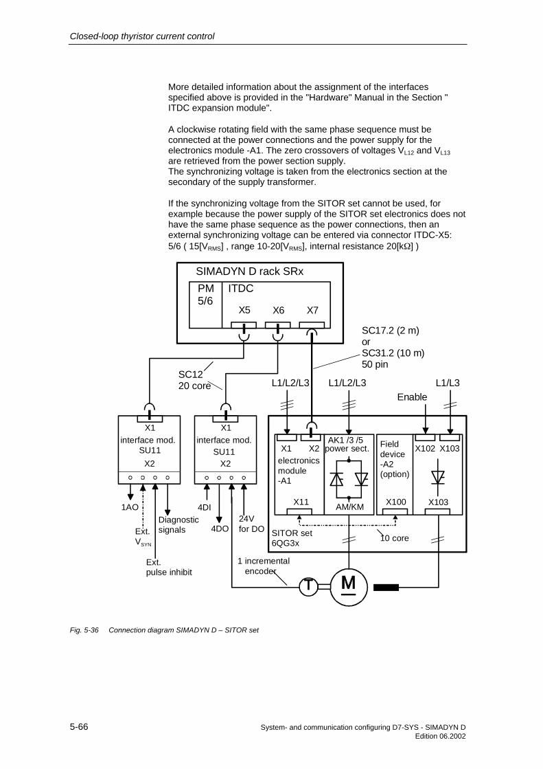
Closed-loop thyristor current control
5-66 System- and communication configuring D7-SYS - SIMADYN DEdition 06.2002
More detailed information about the assignment of the interfacesspecified above is provided in the "Hardware" Manual in the Section "ITDC expansion module".
A clockwise rotating field with the same phase sequence must beconnected at the power connections and the power supply for theelectronics module -A1. The zero crossovers of voltages VL12 and VL13are retrieved from the power section supply.The synchronizing voltage is taken from the electronics section at thesecondary of the supply transformer.
If the synchronizing voltage from the SITOR set cannot be used, forexample because the power supply of the SITOR set electronics does nothave the same phase sequence as the power connections, then anexternal synchronizing voltage can be entered via connector ITDC-X5:5/6 ( 15[VRMS] , range 10-20[VRMS], internal resistance 20[kΩ] )
SIMADYN D rack SRxPM5/6
ITDC
X1 X2
X11 X100
L1/L2/L3
SITOR set6QG3x
AK1 /3 /5
X5 X6 X7
power sect.
X103
Fielddevice -A2(option)
electronicsmodule-A1
interface mod.SU11
interface mod.SU11
SC1220 core
X1X1
X2 X2
1AO
Ext. VSYN
Ext. pulse inhibit
Diagnosticsignals
4DI
4DO
X102
Enable
X103
AM/KM
10 core
24V
SC17.2 (2 m)orSC31.2 (10 m)50 pin
L1/L2/L3 L1/L3
1 incremental encoder
for DO
Fig. 5-36 Connection diagram SIMADYN D – SITOR set

Closed-loop thyristor current control
System- and communication configuring D7-SYS - SIMADYN D 5-67Edition 06.2002
The direct connection between the SITOR set 6QG2x/6QG3x and theSITOR interface ITDC-X7 is established using pre-assembled cablesSC17.2 (2 m) and SC31.2 (10 m).
Connections to the drive converter can also be established using theadapter module "C" and cables SC17.2 (2 m) and SC31.2 (10 m)(→ Catalog DA91, SITOR thyristor sets).
This adapter should be used to connect two drive converters in parallel.For sets connected in parallel, it should be decided which of the twocurrent actual values should be transferred to the ITDC expansionmodule.Signals can be coupled-in or coupled-out at the adapter modules.
No changes have to be made at the SITOR sets and the expansionmodule.
5.5.2 SITOR cabinet
SITOR cabinet units 6QC5 are connected via the SE20.2 interfacemodule to the SITOR interface of the ITDC expansion module.
The drive converter signals are connected to the SE20.2 and from there,transferred floating to the ITDC.
The SE20.2 interface module can be inserted in the SIMADYN D subrackwhere it occupies three slots. The module has a rear connector to inputthe voltage. However, it does not have a coupling to the backplane bus.The depth of the modules differ.
Synchronization to the line supply is realized using the SA60.1synchronizing module. The transformer has a delta configuration on theline side. This means that this phase rotation must be taken intoconsideration at PA6.XDA.
The SA60.1 synchronizing module comprises an SA61 transformermodule and the SA20.1 line supply sensing module. These areconnected through a ribbon cable.
The line supply voltage is connected, with a clockwise rotating field, tothe screw terminals of the transformer module SA61-X2.The transformed voltages are processed on the SA20.1 electronicsmodule and are transformed to the screw terminals of the SE20.2 -X6interface module via screw terminals -X2.The zero crossover signals of phase-to-phase voltages VL12, VL13 and thesynchronizing voltage are transferred to the ITDC -X7 expansion modulevia the SITOR interface SE20.2-X3.
When shipped, the SA60.1 synchronizing module is pre-set to a ratedinput voltage of 400 V (Dip switches S1:3, S1:7 and S2:3 are closed).
For more detailed information on this module, please refer to thedescription of the SA60.1 synchronizing module.
Synchronizingvoltages SA60

Closed-loop thyristor current control
5-68 System- and communication configuring D7-SYS - SIMADYN DEdition 06.2002
Connector X3 of the SE20.2 is directly connected to the SITOR interfaceX7 of the ITDC expansion module.
The power section is connected via connectors X1 and X2.
The firing pulses are output with electrical isolation at connector SE20.2-X1 and terminate in the SITOR cabinet at the pulse distribution (e.g.6QM2200).For bridges which are connected in parallel, the distribution is realizedwithin the SITOR cabinet.
The firing pulses are transferred together with a ground cable.
The shields are grounded at the SE20.2 and the pulse distribution andcan be separated at the pulse distribution.
The connector assignments can be taken from the User Manual "SITORinterface SE20.2".
The actual values and monitoring signals are collected at the transfermodule of the SITOR cabinet from where they are transferred toconnector SE20.2-X2.
• Shielding (-X2: z2 and z26)The shields are grounded at the SE20.2 and in the SITOR cabinet andcan be separated in the cabinet.
• Voltage actual value (-X2: b4 (+) , z4 (-) )The output voltage is provided from a transducer (e.g. LEM electronicPT), and supplies the actual value signal as analog DC voltage orcurrent signal. The actual value should be normalized at the loadresistor module -A1 (on the lefthand component side of the SE20.2).The voltage actual value can also be fed from connector -X9 of theinterface module where it is connected to a load resistor.If the voltage actual value is not used, then the input on the loadresistor module -A1 should be short-circuited (e.g. inserting a jumperfrom R1+R2)
• Temperature monitoring (-X2: b8)The SITOR cabinet does not have an actual temperature monitoringfunction. However, temperature monitoring can be practically derivedfrom the "Fan failure" signal of the fan flow monitor. Temperaturemonitoring is provided for air-water cooling systems.When a fault condition develops, the input of the SE20.2 is open orlogical "0".For disturbance-free operation, the input is kept at logical "1".The supply for the NO contact of the airflow monitoring can be takenfrom SE20.2 (external 24[V]).If the signal is not used, it can be permanently connected to 2P24 orcan be suppressed in the closed-loop thyristor current control(SOL.HWM bit3=0).
ConnectionITDC - SE20.2 -6QG5xx
Firing pulses
Actual values andmonitoringfunctions

Closed-loop thyristor current control
System- and communication configuring D7-SYS - SIMADYN D 5-69Edition 06.2002
• Current actual values (-X2: z12, b12, b14 and z14)The current can be formed in the cabinet or at the interface module.
1. Generating the actual value in the SITOR cabinet:The current actual value is generated in the SITOR cabinet using ashunt (e.g. LEM electronic CT) or using aCT with load resistor and rectification and is transferred as current orvoltage signal to SE20.2-X2:b12 and z12.The signals are converted with the load resistor at the load resistormodule –A2 (righthand component side of the SE20.2), and arenormalized by appropriately inserting the load resistors.
2. Generating the actual value on the SE20.2:Three or two CTs in a V circuit configuration can be connected to theSE20.2-X2 on the three-phase side of the SITOR cabinet. A loadresistor is connected across the current actual value in the plant. If therectification is used, the 0 Ω resistors R3 and R9 should be removedfrom the SE20.2 board and 0 Ω resistors should be inserted forresistors R2, R10 and R15, R8. In this case, the maximum current is 1A.− When using two CTs in a V circuit configuration, the first CT is
connected to connections b12 and z12; the second CT toconnections b14 and z14.The current actual value can also be fed from connector -X9 of theinterface module or it can also be output through a load resistorthere.If the current actual value is not used, then the input should beshort-circuited, e.g. by jumpering R1/R2 on the load resistormodule -A2.
− When using three CTs, a neutral point is formed in the SITORcabinet. The remaining three CT connections are connected toconnections -X2: b12, z12 and b14.
• Fuse monitoring (-X2: b16)The external 2P24 voltage is connected to -X2:b16 via the NC contactof the fuse monitoring.If there is no fuse monitoring (e.g. for parallel circuit configurations),this monitoring function can be derived from the current monitoring ofeach bridge.
− The sum signal is obtained by connecting all of the NC contacts inparallel. Using a parallel circuit configuration of the NC contacts, afault signal is output if any of the bridges, connected in parallel, fail.In this case, the current limit should be reduced, depending on thefailed bridges, using additional digital inputs of the SIMADYN Dsystem!
• Absolute value of the line supply voltage (-X2: d22 and d24d)pulse suppression (-X2: b30)
1. Evaluating the absolute value of the line supply voltage via SE20.2The synchronizing module SA60.1 generates an absolute value of theline supply voltage |Vsupply|. This voltage signal at -X2:d22 (+), d24 (-)and the pulse supply voltage at -X2:b30 are individually monitoredagainst a limit and are internally OR’ed to form an "Undervoltage"

Closed-loop thyristor current control
5-70 System- and communication configuring D7-SYS - SIMADYN DEdition 06.2002
signal. The absolute value of the line supply voltage can also be read-in via bus connector -X9 and via -X5 / -X6.
2. Evaluating the absolute value of the line supply voltage via SA60.1The SA60.1 synchronizing module generates a digital undervoltagesignal (line sensing module SA20.1 X2 pins 9, 10 or 11). This signalcan be connected (using a suitable circuit) in series with the relayassociated with the "Pulse voltage supply" monitoring (e.g.6QM1038x), and evaluated using a separate digital input of theSIMADYN D system (SOL.HWH bit4=0 \ SOL.UNM=0).
NOTE The pulse undervoltage signal should be evaluated according to 1. or2., because, if the power supply voltage fails, the thyristors could faildue to a high trigger power loss.
• External I=0 signal (-X2: b28 and z28)Standard applications use the internal I=0 signal of the SE20.2. If anexternal I=0 signal (digital signal, max. 60V) is to be supplied, e.g.from a blocking voltage sensing, then the wire jumper IA-IB (at thebottom lower component side of the SE20.2) should be changed overto IA-IC (solder connection). In this case, the internal I=0 signal is noteffective. Adaptation to the input signal is realized via the voltagedivider R44, R45 and R46. The internal threshold is 3.6V.
The I=0 signal evaluation is not generally required. In this case, the inputat the change-over logic stage SOL.NZM should be set to 1 so that theinternal zero current signal is used. However, in this case it should betaken into consideration that the drives lose some of their dynamicresponse at torque reversal!
Standard applications with SITOR cabinets provide a special type of fieldsupply. In this case, the "Field current setpoint output" block FB FCSshould not be configured, and the fault evaluation associated with thefield current monitoring at input SOL.HM1 \ bit 14 should be set to 0.
The monitoring signals are, with the exception of the field currentmonitoring, defined so that a logical "1" signal represents a fault-freestatus.
A logical "0" signal or an open-circuit input i.e. wire breakage, results in afault detection (masking of the switch-over logic stage at inputsSOL.HWM/HM1/HM2).
Many signals are output via relays in the SITOR cabinet. If possible, thewiring should be realized as follows to provide the most flexibleevaluation possible, regarding other evaluation units:
2P24
Fault/error-free status
Monitoring signal to the transfer module
Field supply
Connecting-up themonitoring signals

Closed-loop thyristor current control
System- and communication configuring D7-SYS - SIMADYN D 5-71Edition 06.2002
NOTE The connector assignment for -X2 should be taken from the UserManual "SITOR interface SE20.2". The connecting cable for actualvalue/monitoring functions can, according to the Section "Connectingcables" be configured by customers themselves.
Poweract. valuesensing
pulsedistribut.
e.g.:Voltage,currentactual value
SITOR cabinet 6QC5x
SIMADYN D rack SRx
PM5/6
ITDC
X5 X6 X7
X1
L1/L2/L3
X121Interf. module
SU11Interf. module
SU11
SC1220 core
X1X1
X2 X2
1AO
Ext. VSYN
Ext. pulse inhibit
Diagnosticsignals
4DI
4DO powersupply
24V
SC17.2 (2 m)orSC31.2 (10 m)50 core
1 incremental encoder
SE20.2
X3 X5 X6 X2 X1
IT41
X7
Line sensingSA21
X1
X2
Transf. VSYN
SA61
X2
X1
Interf. moduleSU10
Interf. moduleSU10
X1X1
X2 X2
powersupply
8DO 8DO 5DI 3DI 8DI 4AI
24V 24Vinternal external
L1/L2/L3
Monitoringe.g.:Overvolt.,undervolt.,current flow,airflow,fuse,ground fault
Fig. 5-37 Connecting diagram SIMADYN D – SITOR cabinet

Closed-loop thyristor current control
5-72 System- and communication configuring D7-SYS - SIMADYN DEdition 06.2002
Connection 1:1
Pair No. Contact assignmentZ2 is cable, 4) is shield connectionCore A Core B
1 d4 b4
2 d6 b6
3 d8 b8
4 d10 b10
5 d12 b12
6 d14 b14
7 d20 b20
8 d22 b22
9 d24 b24
10 d26 b26
11 d28 b28
12 d30 b30
13 Not assigned
(contact Z2 with contact Z2)
1) 2 x shell-type enclosure A with catches:Order No.:A09060480501 GDS A-FLManufacturer: Harting
2) 2 x insulating bodies for crimp connection:Order No.:A09060483201 (48 pin)Manufacturer: Harting
3) Control cable 13 x 2 x 0.18:Order No.:6FC9343-0ACManufacturer: Siemens
4) 2 x cable LIY 1 x 0.5 / 1.6 ws:(shield connection)
5) Spring-mounted contacts to crimp:Order No.:09060006421 CrimpManufacturer: Harting
Connecting cable,firing pulses (X1)

Closed-loop thyristor current control
System- and communication configuring D7-SYS - SIMADYN D 5-73Edition 06.2002
Connection 1:1
Pair No. Contact assignment(Z2 is cable, 4) is shield connection)Core A Core B
1 b4 z42 b8 z83 b12 z12
(b14) (z14)4 b16 z165 b18 z186 b20 z207 b22 z228 b24 z249 b28 z28
10 b30 z30
(contact Z2 with contact Z2)
Connection b14/z14 only for current actual value sensing in a V circuitconfiguration
1) 2 x shell-type enclosure A with catches:Order No.:A09060480501 GDS A-FLManufacturer: Harting
2) 2 x insulating bodies for crimp connectionOrder No.:A09060483201 (48 pin)Manufacturer: Harting
3) Control cable 10 x 2 x 0.18 – W -:Order No.:6FC9343-0ABManufacturer: Siemens
4) 2 x cable LIY 1 x 0.5 / 1.6 ws:shield connection
5) Spring-mounted contacts to crimp:Order No.:09060006421 CrimpManufacturer: Harting
Connecting cable,actual values (X2)

Closed-loop thyristor current control
5-74 System- and communication configuring D7-SYS - SIMADYN DEdition 06.2002
5.6 Definitions
All of the current-dependent quantities are referred to the rated systemcurrent CAV.ARC (e.g. rated motor current) and normalization factorCAV.NF, specified by the user.
All of the voltage-dependent quantities are referred to the rated systemvoltage EMF.ARV (e.g. rated motor voltage) and the normalization factorEMF.NF.
If the instantaneous drive converter output voltage Vd is the same as thevalue configured at input ARV (Vd=ARV), then in the normalizedrepresentation type (NF=1), the output value YUA=1.
For DZ=1, a firing pulse pair of a phase is constantly output in theconstellation 1-4, 2-5, 3-6 or 4-1, 5-2, 6-3.
1
3
5 2
6
4
D1
H4
Z3
D3
H6
Z5
D5H2Z1
H5Z4
H3
Z2
H1
Z6
D2
D6
D4
L2L1 L3
Hx = main pulseZx = second pulseDx = double pulse
Fig. 5-38 Assignment of the firing pulses to the semiconductor devices
Normal operation with the actual firing pulses is resumed as soon as thedouble firing mode has been de-activated.The switch-over logic stage corrects the current controller and thereforethe firing angle setpoint during double firing operation.
5.6.1 Formats
16#FFFF = hexadecimal value
The “Firing angle” format is an internal format for calculations. A valuecan be converted into degrees using the following formula:
901ASG α−=
Closed-loopcurrent control
Double firing
Format data
Firing angle

Closed-loop thyristor current control
System- and communication configuring D7-SYS - SIMADYN D 5-75Edition 06.2002
The value range of the ASG format
angle iring ][0 90180
[ASG] 1 0 1
toscorrespondf°=°⇔°⇔°
=+⇔⇔−
The line supply frequency is emulated as a line supply value using a16MHz counter (21 bit resolution). The format is specified with [16MHz].A counter status of 320000 = 50 [Hz],
266667 = 60 [Hz]
5.6.2 Designations
Various symbols are used in this document.
Dimension data [ A , V , Hz , kHz , Ω , mΩ, ° ]
Value range value data , limit data
Comments ( text )
Connection → , this is also used as reference.
Result, sequence of ⇒
Change
16MHz

Closed-loop thyristor current control
5-76 System- and communication configuring D7-SYS - SIMADYN DEdition 06.2002
5.7 Abbreviations
A-Z Significance 1 Significance 2
B6C Fully-controlled 3-phase bridge(B6)A(B6)C
Anti-parallel circuitFully-controlled B6 bridge
CFC Graphic configuringD7-SYS Program for CFCFB Function blockITDC Interface Technology DC DC currentHW HardwareLE-Bus Local expansion busLE-I1 Interrupt 1 for ITDC from PM
M0 No torque direction selectedM1 Torque direction 1M2 Torque direction 2
SW SoftwareSITOR Sitor family of drive converters
TA Armature time constant Sampling time =computation cycle
U SYN Synchronizing voltageα Firing angle1Q Operation in only one current
direction4Q Operation in only two current
directions
Table 5-13 Abbreviations
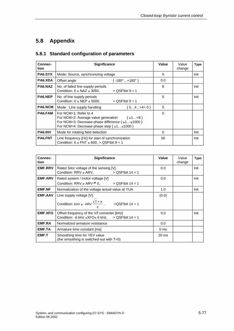
Closed-loop thyristor current control
System- and communication configuring D7-SYS - SIMADYN D 5-77Edition 06.2002
5.8 Appendix
5.8.1 Standard configuration of parameters
Connec-tion
Significance Value Valuechange
Type
PA6.SYX Mode: Source, synchronizing voltage 0 Init
PA6.XDA Offset angle -180°…+180° 0.0
PA6.NAZ No. of failed line supply periodsCondition: 0 ≤ NAZ ≤ 3050, > QSF\bit 9 = 1
8 Init
PA6.NEP No. of line supply periodsCondition: 0 ≤ NEP ≤ 5000, > QSF\bit 9 = 1
5 Init
PA6.NCM Mode : Line supply handling 0…4 , >4= 0 0
PA6.FAM For NCM=1: Refer to 4For NCM=2: Average value generation ≥1…<8 For NCM=3: Decrease phase difference ≥1…≤1000 For NCM=4: Decrease phase step ≥1…≤1000
0
PA6.INV Mode for rotating field detection 0 Init
PA6.FNT Line frequency [Hz] for start of synchronizationCondition: 6 ≤ FNT ≤ 600, > QSF\bit 9 = 1
50 Init
Connec-tion
Significance Value Valuechange
Type
EMF.RRV Rated Sitor voltage of the sensing [V].Condition: RRV ≥ ARV, > QSF\bit 14 = 1
0.0 Init
EMF.ARV Rated system / motor voltage [V]Condition: RRV ≥ ARV≠ 0, > QSF\bit 14 = 1
0.0 Init
EMF.NF Normalization of the voltage actual value at YUA 1.0 Init
EMF.AAV Line supply voltage [V].
Condition: 3
2ARV AAV
π∗⋅≥ , >QSF\bit 14 = 1
(0.0)
EMF.XFO Offset frequency of the V/f converter [kHz]Condition: -6 kHz ≤XFO≤ 6 kHz, > QSF\bit 14 = 1
0.0 Init
EMF.RA Normalized armature resistance 0.0
EMF.TA Armature time constant [ms] 0 ms
EMF.T Smoothing time for YEV value(the smoothing is switched-out with T=0)
20 ms

Closed-loop thyristor current control
5-78 System- and communication configuring D7-SYS - SIMADYN DEdition 06.2002
Connec-tion
Significance Value Valuechange
Type
SOL.TH0 Thyristor hold-off time [ms]Condition: 0.5 ms ≤ TH0 ≤ 131 ms, > YW2\bit10 =1
10 ms Init
SOL.TCP Thyristor pulse suppression time [ms]Condition: 0.0 ms ≤ TH0 ≤ 20000 ms , > YW2\bit10 =1
20 ms Init
SOL.TCD Monitoring time for torque change M1 ⇔ M2 1000 ms
SOL.IPL Pulse inhibit = 1 effective immediately ! 0
SOL.UNM Mode: Handling the undervoltage (Sitor) 2
SOL.ION On command, closed-loop thyristor current control 0
SOL.IOF Off command, closed-loop thyristor current control 0
SOL.ON1 Enable, only torque direction M1 0
SOL.OF1 Off command, torque direction M1 0
SOL.ON2 Enable, only torque direction M2 0
SOL.OF2 Off command, torque direction M2 0
SOL.IEF Mode: Use calculated EMF value(FB EMF available )
1
SOL.NZM Zero current signal from the SITOR set Y/N=0/1 0
SOL.WC1 Current setpoint 1 (or connection) 0.0
SOL.WC2 Current setpoint 2 (or connection) 0.0
SOL.WCL Switch-on threshold for torque direction (abs. value) 0.01
SOL.TM0 Monitoring time for torque direction M0 2000ms
SOL.IF1 Fault, external 1 0
SOL.IF2 Fault, external 2 0
SOL.HMH Enables bits for the hardware signaling word YHW 16#FFFF
SOL.HM1 Enables bits for the fault word YF1 16#FFFF
SOL.HM2 Enables bits for the fault word YF2 16#FFFF
SOL.HP1 Enables bits from YF1 for immediate pulse inhibit 16#0000
SOL.HP2 Enables bits from YF2 for immediate pulse inhibit 16#0000
SOL.MNE Group inhibit, fault word YF1 and YHW 16#067E
Connec-tion
Significance Value Valuechange
Type
CSP.WCU Positive current limit (absolute value) 1.0
CSP.WCL Negative current limit (absolute value) 1.0
CSP.GLI Gradient for setpoint smoothing 0.6
CSP.IL Gradient for integrator inhibit 0.6

Closed-loop thyristor current control
System- and communication configuring D7-SYS - SIMADYN D 5-79Edition 06.2002
Connec-tion
Significance Value Valuechange
Type
CPC.VCI Current setpoint at the discontinuous limit 0 < VCI <discontinuous limit
0.1
CPC.ALP Pre-control angle in the discontinuous range [°],≥25°…30°≤
25.0
Connec-tion
Significance Value Valuechange
Type
CAV.RRC Rated DC current of the SITOR set [A]Condition: RRC ≥ ARC , > QSF\bit 12 = 1
0.0 Init
CAV.ARC Rated system / motor current [A]Condition: RRC ≥ ARC ≠ 0 , > QSF\bit 12 = 1
0.0 Init
CAV.NF Normalization of the current actual value at YCCondition: NF > 0 ,
1.0 Init
CAV.XFO Offset calibration [kHz] ≥-6.0…+6.0≤ 0.0 Init
CAV.XF2 Current-dependent inverter stability limit [1] ≥0.0…0.2≤Condition: 0.0 ≤ XF2 ≤ 0.2, > QSF\bit 12 = 1
0.0 Init
CAV.IAV Correction for the inverter stability limit [1] ≥0.7…1.3≤Condition: 0.7 ≤ IAV ≤ 1.3, > QSF\bit 12 = 1
1.0 Init
CAV.AL1 Positive correction, current actual value sensingCondition: -0.1 ≤ AL1 ≤ 0.1,
0.0 Init
CAV.AL2 Negative correction, current actual value sensingCondition: -0.1 ≤ AL2 ≤ 0.1,
0.0 Init
CAV.CX1 Max. current for torque direction M1 (abs. value) 0.1
CAV.CX2 Max. current for torque direction M2 (abs. value) 0.1
Connec-tion
Significance Value Valuechange
Type
CPI.CLU Limit of the current-dependent inverter stability limit [°] 150.0
CPI.ALU Inverter control limit, firing angle [°] 150.0 Init
CPI.ALL Rectifier control limit, firing angle [°] 30.0 Init
CPI.SVC Mode: Pre-control of the CPI 0
CPI.KP Proportional gain [1] 0.01
CPI.TN Integral action time [ms] 10000 ms
CPI.PC Inhibit integrator component 0

Closed-loop thyristor current control
5-80 System- and communication configuring D7-SYS - SIMADYN DEdition 06.2002
Connec-tion
Significance Value Valuechange
Type
PC6.LDP Selects the firing pulse waveform: LDP = 0: 7kHz pulse chain,LDP = 1: Long pulses.
0 Init
PC6.LDU Absolute inverter (INV) control limit [°]Condition: 90 ≤ LDU ≤ 180, > QSF\bit 9 = 1
150 Init
PC6.LDL Absolute rectifier (RECT) control limit [°]Condition: 0 ≤LDL ≤ 90, > QSF\bit 9 = 1
30 Init
PC6.LMP Main pulse length [ms] < 45[°] el. 1.1ms
PC6.LFP Second pulse length [ms] < 45[°] el. 1.1ms
PC6.AQL Test operation: Firing angle setpoint [°] 150
PC6.AWS Shift to INV operation: Firing angle setpoint [°]Condition: 90 ≤ AWS ≤ 180, > QSF\bit 9 = 1
150 Init
PC6.DAG Max. angular change/TA in the direction of rectifier op.Condition: 0 ≤ DAG ≤ 180, > QSF\bit 9 = 1
60 Init
PC6.DAW Max. angular change/TA in the direction of inverter op.Condition: 0 ≤ DAW ≤ 180, > QSF\bit 9 = 1
150 Init
PC6.DIL Tolerance of the pulse position [°] 1.0
PC6.DIZ No. of permissible limit violations DIL 3
PC6.DZ Operation: Double firing 0
Connec-tion
Significance Value Valuechange
Type
FCS.RRC Rated current of the field current rectifier [A]Condition: RRC ≥ ARC ≠ 0, > QSF\bit 12 = 1
0.0 Init
FCS.ARC Rated field current of the DC motor excitation [A]Condition: RRC ≥ ARC ≠ 0, > QSF\bit 12 = 1
0.0 Init
FCS.NF Normalization factor to interpret the setpoint 1.0 Init
FCS.ION On command, field current 0
FCS.IOF Switch-out field setpoint output 0
FCS.FC Field current setpointCondition: FC ≥ 0 > QSF\bit 12 = 1
0
FCS.EN Enables inputs ION,IOF 0
FCS.IE Option: Field present 0
FCS.T Delay time when switching-in and when switching-outCondition: 0 ≤ T ≤ 100000 ms, > QSF\bit 12 = 1.
1500 ms Init

Closed-loop thyristor current control
System- and communication configuring D7-SYS - SIMADYN D 5-81Edition 06.2002
5.8.2 Standard connections
Connec-tion
Type Significance Source
PA6.ZPA ON NV Firing pulse number PC6.ZPA
PC6.CTH ON NV Firing pulse output, time value PA6.CTH
PC6.CTS ON NV Time value, start of FB PA6 PA6.CTS
PC6.EN ON NV Enable firing angle controller PA6.RDY
PC6.X6R ON NV Numerical = 60° of the line supply periods [16 MHz] PA6.Y6R
PC6.XAS ON NV Firing angle actual value [ASG] PA6.XAS
PC6.WAS ON SP Firing angle setpoint [ASG] CPI.Y
PC6.ICC ON NV Control word SOL.QCC
PC6.ACI ON NV Handshake from the CAV block CAV.ACO
EMF.XC ON SP Current actual value (with sign) CAV.YC
EMF.ACI ON NV Handshake from the PC6 block PC6.ACO
SOL.ION ON SP On command of the closed-loop thyristor current control (,FCSpresent)
FCS.QON
SOL.DZM ON NV Operating signal, double firing PC6.DZM
SOL.XC ON NV Current actual value (with sign) CAV.YC
SOL.XEV ON NV EMF value calculated EMF.YEV
SOL.QSC ON NV Fault word from CAV CAV.QSF
SOL.QSM ON NV Fault word from EMF EMF.QSF
SOL.QSA ON NV Fault word from PA6 PA6.QSF
SOL.QSP ON NV Fault word from PC6 PC6.QSF
SOL.QSS ON NV Fault word from FCS (, if programmed) FCS.QSF
CAV.IM1 ON NV Torque direction M1 operational ⇒ “+” = CX1 SOL.Q01
CAV.IM2 ON NV Torque direction M2 operational ⇒ “-” = CX2 SOL.Q02
CAV.ACI ON NV Handshake from the EMF block EMF.ACO
CPC.WC ON NV Current setpoint (absolute value) CSP.YWC
CSP.WC ON SP Current setpoint from the switch-over logic stage SOL.YWC
CPI.WC ON SP Current setpoint (absolute value) CSP.YWC
CPI.XC ON NV Current actual value (with sign) CAV.YC
CPI.SV ON NV Setting value, integrator from the switch-over logic stage SOL.YSV
CPI.S ON NV Setting the integrator with value SV SOL.QCS
CPI.EN ON NV Controller enable SOL.QCE
CPI.ILU ON NV Inhibits the integrator, positive direction CSP.QIU
CPI. ILL ON NV Inhibits the integrator, negative direction CSP.QIL
NV=Connection requiredSP=Standard connection according to the standard configuring
Connections,internal

Closed-loop thyristor current control
5-82 System- and communication configuring D7-SYS - SIMADYN DEdition 06.2002
Connec-tion
Significance Source
SOL.IPL Pulse inhibit = 1, effective immediately!
SOL.ION On command, closed-loop thyristor current control
SOL.IOF Off command, closed-loop thyristor current control
SOL.WC1 Current setpoint 1
SOL.WC2 Current setpoint 2
SOL.IF1 External fault 1
SOL.IF2 External fault 2
SOL.MNE Group inhibit, fault words YF1 and YHW
SOL.QUI Acknowledgement, faults YF1 and YF2
FCS.ION On command, field current
FCS.IOF Switch-out field setpoint output
FCS.FC Field current setpoint
FCS.EN Enable inputs ION,IOF
5.8.3 Configuring example for normalization
The closed-loop thyristor current control can be used with normalized(standard) and absolute values.
For the example for the settings of the system parameters, the followingare used as basis: A 6QG3230-2AB SITOR set (3-ph./400[V], AC 30[A] +field) and a DC motor with the rated data:
Armature: VA=400 [V], IA=10 [A], RA=500 [mΩ],Field: IF=1.5 A
and the phase-to-phase line supply voltage: UL=400 V.
5.8.3.1 Representation with normalized values
Parameter SignificanceCAV.RRC = 30[A] Rated DC current [A] of the SITOR set
current [A] for VIact=5 V/CT SITOR
CAV.ARC =10 [A] Rated system/motor current [A] current [A] forCAV.YC=1
CAV.NF =1 Current normalization factor
CAV.CX1=+1.5 Absolute value, overcurrent, torque direction 1 [%]permissible overcurrent 15 A
CAV.CX2=+1.5 Absolute value, overcurrent, torque direction 2 [%]permissible overcurrent -15 A
CAV.YC Current actual values, normalized1... 0 1...CAV.YCˆ10A0A10A +−==+⇔⇔−
Connections,external
Current actualvalue sensing
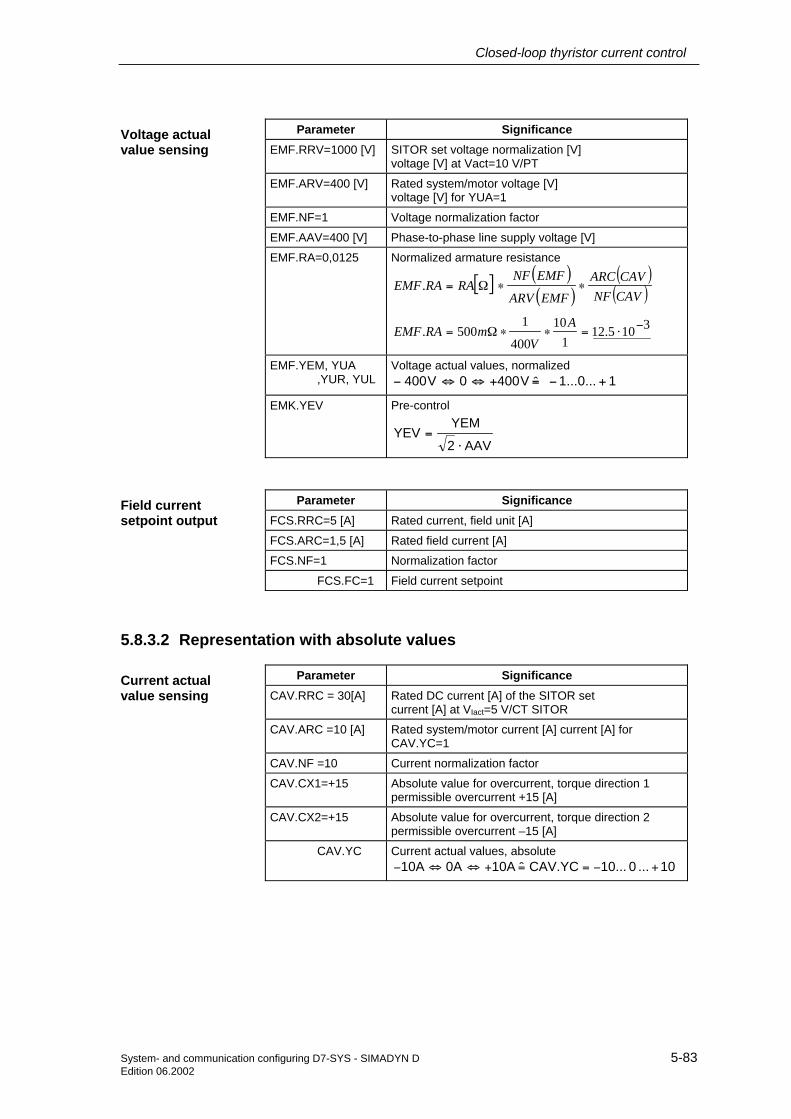
Closed-loop thyristor current control
System- and communication configuring D7-SYS - SIMADYN D 5-83Edition 06.2002
Parameter SignificanceEMF.RRV=1000 [V] SITOR set voltage normalization [V]
voltage [V] at Vact=10 V/PT
EMF.ARV=400 [V] Rated system/motor voltage [V]voltage [V] for YUA=1
EMF.NF=1 Voltage normalization factor
EMF.AAV=400 [V] Phase-to-phase line supply voltage [V]
EMF.RA=0,0125 Normalized armature resistance
[ ] ( )( )
( )( )
3105.121
10400
1500.
.
−⋅=∗∗Ω=
∗∗Ω=
AV
mRAEMF
CAVNFCAVARC
EMFARV
EMFNFRARAEMF
EMF.YEM, YUA,YUR, YUL
Voltage actual values, normalized1...0...1 ˆV4000V400 +−=+⇔⇔−
EMK.YEV Pre-control
AAV2
YEMYEV
⋅=
Parameter SignificanceFCS.RRC=5 [A] Rated current, field unit [A]
FCS.ARC=1,5 [A] Rated field current [A]
FCS.NF=1 Normalization factor
FCS.FC=1 Field current setpoint
5.8.3.2 Representation with absolute values
Parameter SignificanceCAV.RRC = 30[A] Rated DC current [A] of the SITOR set
current [A] at VIact=5 V/CT SITOR
CAV.ARC =10 [A] Rated system/motor current [A] current [A] forCAV.YC=1
CAV.NF =10 Current normalization factor
CAV.CX1=+15 Absolute value for overcurrent, torque direction 1permissible overcurrent +15 [A]
CAV.CX2=+15 Absolute value for overcurrent, torque direction 2permissible overcurrent –15 [A]
CAV.YC Current actual values, absolute10... 0 10...CAV.YCˆ10A0A10A +−==+⇔⇔−
Voltage actualvalue sensing
Field currentsetpoint output
Current actualvalue sensing

Closed-loop thyristor current control
5-84 System- and communication configuring D7-SYS - SIMADYN DEdition 06.2002
NOTE The blocks use normalized values for internal calculations. This means,in this particular case, the current setpoint and the current actual valuefor the current controller CPI should be divided by the normalizationfactor CAV.NF using a division block (CPI.WC/CAV.NF andCPI.XC/CAV.NF).
Refer to the example, the following applies:
• For DIV block 1:
− Connect CAV.YC with X1Enter the configured value of CAV.NF=10 at X2Connect output Y of DIV block 1 with CPI.XC
• For DIV block 2:
− Connect SOL.YWC with X1Enter the configured value of CAV.NF=10 at X2Connect output Y of DIV block 2 with CPI.WC
The division blocks should be configured in the sequence that they arerun directly in front of the current controller block CPI!
Parameter SignificanceEMF.RRV=1000 [V] SITOR set voltage normalization [V]
voltage [V] at Vact=10 V/PT
EMF.ARV=400 [V] Rated system/motor voltage [V]voltage [V] for YUA=1
EMF.NF=400 Voltage normalization factor
EMF.AAV=400 [V] Phase-to-phase line voltage [V]
EMF.RA=0,0125 Normalized armature resistance
[ ] ( )( )
( )( )
[ ] [ ][ ] 310500
10A10
V400400m500RA.EMF
CAVNFCAVARC
EMFARVEMFNF RARA.EMF
−⋅=∗∗Ω=
∗∗Ω=
EMF.YEM, YUA,YUR, YUL
Voltage actual values, normalized400...0...400 ˆV4000V400 +−=+⇔⇔−
EMK.YEV Pre-control
AAV21...0...1
ˆAAV2
400...0...400AAV2
YEMYEV⋅
+−=
⋅
+−=
⋅=
YEV is, as shown in the normalized representation,normalized to 1 and referred to the line supplyamplitude. For normalized and absolute values, YEVhas the same value range!
Voltage actualvalue sensing

Closed-loop thyristor current control
System- and communication configuring D7-SYS - SIMADYN D 5-85Edition 06.2002
Parameter SignificanceFCS.RRC=5 [A] Rated field unit current [A]
FCS.ARC=1.5 [A] Rated field current [A]
FCS.NF=1.5 Normalization factor
FCS.FC=1.5 [A] Field current setpoint
NOTE The system must be restarted (Initialization quantities) when changingbetween representation with normalized or absolute values.
Field currentsetpoint output

Closed-loop thyristor current control
5-86 System- and communication configuring D7-SYS - SIMADYN DEdition 06.2002

System- and communication configuring D7-SYS - SIMADYN D I-1 Edition 12.2003
Index
$ $ signals ...................................................................................................................................... 2-19
7 7-segment display ....................................................................................................................... 2-46
Acknowledge error ................................................................................................................... 2-46
A Application example PROFIBUS DP........................................................................................... 3-63
Configuring slaves.................................................................................................................... 3-80 Assigning a name.......................................................................................................................... 2-3 Assigning names
Philosophy for assigning names ................................................................................................ 4-2
B Basic clock cycle ......................................................................................................................... 2-27 Basic CPU clock cycle................................................................................................................. 2-21 Basic information, communications............................................................................................... 3-2 Behavior under fault conditions................................................................................................... 2-40 BICO technology
Changing interconnections..................................................................................................... 3-218 general ................................................................................................................................... 3-217 Interconnection possibilities ................................................................................................... 3-220
C CFC chart (Continuous Function Chart)........................................................................................ 2-7 CFC editor ............................................................................................................................2-7, 2-16
Creating interconnections ........................................................................................................ 2-16 Margins..................................................................................................................................... 2-11 Parameterizing dialogs............................................................................................................... 2-8
COM PROFIBUS......................................................................................................................... 3-58 Communicaions
SIMATIC Operator Panels ..................................................................................................... 3-292 Communication blocks
Address connections AT, AR, US ............................................................................................ 3-10 Central coupling blocks ............................................................................................................ 3-17 Firmware status, ECL, ECO connection .................................................................................. 3-15 Initialization input CTS................................................................................................................ 3-9 MOD connection....................................................................................................................... 3-11 Status display, output YTS....................................................................................................... 3-15 Transmitter and receiver .......................................................................................................... 3-18
Communication utilities

Index
I-2 System- and communication configuring D7-SYS - SIMADYN D Edition 12.2003
Overview.....................................................................................................................................3-8 Communications
WinCC via MPI .......................................................................................................................3-304 WinCC via SINEC H1.............................................................................................................3-306
Communications buffer coupling .................................................................................................3-22 COMSS5 ...................................................................................................................................3-102
Bus parameters ......................................................................................................................3-104 Communication associations..................................................................................................3-106 Loading the database.............................................................................................................3-116 Menu structure........................................................................................................................3-103
Configuring SIMADYN D stations..................................................................................................2-4 Configuring technological connectors .......................................................................................3-217 Consistency check.........................................................................................................................2-7 Coupling modules
Number in the subracks ...........................................................................................................3-20 Coupling to EP3 modules............................................................................................................3-23 Couplings
Data interface ...........................................................................................................................3-20 Mode of operation ....................................................................................................................3-16 Net data structures ...................................................................................................................3-19 Overview.....................................................................................................................................3-2
Couplings on the subrack............................................................................................................3-22 CPU synchronization...................................................................................................................2-27
Configuring the CPU basic clock cycle ....................................................................................2-28 Configuring the interrupt task ...................................................................................................2-30
Cycle errors .................................................................................................................................2-33 Eliminating ................................................................................................................................2-34
D Data consistency .........................................................................................................................2-23 Data transfer mode
Handshake ...............................................................................................................................3-11 Image........................................................................................................................................3-14 Multiple .....................................................................................................................................3-13 Overview...................................................................................................................................3-11 Refresh .....................................................................................................................................3-12 Select........................................................................................................................................3-13
DATX attributes ...........................................................................................................................4-17 Deadtimes ...................................................................................................................................2-21 Display control ...........................................................................................................................3-229
Acquisition block..........................................................................................................3-231, 3-232 Computation- and data transfer times....................................................................................3-235 Configuring .............................................................................................................................3-230 Data entries at the central block.............................................................................................3-230 Hardware and software ..........................................................................................................3-229 Message output block ............................................................................................................3-233
Download in the RUN status .......................................................................................................2-15 drive converter coupling ............................................................................................................3-149 Drive coupling SIMOLINK
Configuring .............................................................................................................................3-166 Function blocks.......................................................................................................................3-171 Settings in HWConfig .............................................................................................................3-167
Drive coupling SIMOLINK Slave settings .........................................................................................................................3-172

Index
System- and communication configuring D7-SYS - SIMADYN D I-3 Edition 12.2003
DUST 2 Configuring ............................................................................................................................. 3-131
DUST1....................................................................................................................................... 3-127 Configuring ............................................................................................................................. 3-127 Configuring example .............................................................................................................. 3-128 Hardware................................................................................................................................ 3-127
DUST2....................................................................................................................................... 3-131 Hardware................................................................................................................................ 3-131
DUST3....................................................................................................................................... 3-133 Central coupling block............................................................................................................ 3-134 Configuring ............................................................................................................................. 3-133 Hardware................................................................................................................................ 3-133 Transmit- and receive block ................................................................................................... 3-135
DUST7....................................................................................................................................... 3-136
E Error differentiation...................................................................................................................... 2-38
F Fast $ signal ................................................................................................................................ 2-20 Features
Computation times of the operating system............................................................................. 2-35 Cyclic tasks .............................................................................................................................. 2-34 Interrupt tasks........................................................................................................................... 2-35 Memory requirement of the operating system ......................................................................... 2-35
Function block Assignment of the input/output blocks to modules..................................................................... 4-8 Assignment to interrupt tasks..................................................................................................... 2-9 Comments ................................................................................................................................ 2-12
Function block types...................................................................................................................... 4-2 Derivatives.................................................................................................................................. 4-2 Standard data type ..................................................................................................................... 4-2
Function blocks Assigning to cyclic tasks ............................................................................................................ 2-9
H hardware address........................................................................................................................ 2-12 Hardware timer............................................................................................................................ 2-28 HWConfig .............................................................................................................................2-5, 2-16
Parameterizing dialogs............................................................................................................... 2-5
I Industrial Ethernet ....................................................................................................................... 3-31 Initialization.................................................................................................................................. 2-36 Interconnecting............................................................................................................................ 2-12 Interrupt-controlled processing.................................................................................................... 2-37
L Libraries......................................................................................................................................... 2-4 Limited number of interconnections ............................................................................................ 2-21

Index
I-4 System- and communication configuring D7-SYS - SIMADYN D Edition 12.2003
Loading the user program Offline loading...........................................................................................................................2-13 Online loading...........................................................................................................................2-13
Local CPU coupling.....................................................................................................................3-22
M Message system...............................................................................................................3-42, 3-239
Communications error message ............................................................................................3-246 Entry logic...............................................................................................................................3-239 Error or alarm message..........................................................................................................3-244 Message entry blocks.............................................................................................................3-239 Message format......................................................................................................................3-244 Message formats....................................................................................................................3-247 Message type description.......................................................................................................3-244 Messages ....................................................................................................................3-241, 3-244 Output format..........................................................................................................................3-252 Overflow message..................................................................................................................3-246 System error ...........................................................................................................................3-247 System error message ...........................................................................................................3-247
MPI coupling..............................................................................................................................3-137 Configuring .............................................................................................................................3-137
N Network
Description..............................................................................................................................3-265 Rigid network..........................................................................................................................3-266 Terminology............................................................................................................................3-265
O OP2............................................................................................................................................3-229 Operating system components....................................................................................................2-36 Operator Panels (SIMATIC) ......................................................................................................3-292
P Parameter access technique for D7-SYS..................................................................................3-214 Parameter changes, status-dependent .....................................................................................3-221 Parameter processing ...............................................................................................................3-254
Cascading...............................................................................................................................3-263 Configuring .............................................................................................................................3-255 Configuring example ..............................................................................................................3-257 Error message........................................................................................................................3-263 Function blocks.......................................................................................................................3-254 Parameter change report .......................................................................................................3-263 Parameter settings .................................................................................................................3-264 PKW blocks ............................................................................................................................3-255 response ID ............................................................................................................................3-261 Task........................................................................................................................................3-261 Telegram structure .................................................................................................................3-255
Peer-to-peer ..............................................................................................................................3-149 Configuring ..................................................................................................................3-149, 3-150 Hardware requirements..........................................................................................................3-149

Index
System- and communication configuring D7-SYS - SIMADYN D I-5 Edition 12.2003
Receiving................................................................................................................................ 3-150 Transmitting............................................................................................................................ 3-149
Pointer-based communications blocks Applications ............................................................................................................................ 3-279 Associated function blocks..................................................................................................... 3-281 Configuring information and instructions................................................................................ 3-282 Examples................................................................................................................................ 3-282 Features ................................................................................................................................. 3-280 Pointer interface ..................................................................................................................... 3-281 Principal mode of operation ................................................................................................... 3-279
Pointer-based communications blocks Introduction............................................................................................................................. 3-278
Process data ............................................................................................................................. 3-270 Blocks CRV, CTV................................................................................................................... 3-274 Channel marshalling blocks ................................................................................................... 3-274 Channels ................................................................................................................................ 3-277 Configuring example .............................................................................................................. 3-272 Diagnostics............................................................................................................................. 3-276 Distribution block .................................................................................................................... 3-276 Function blocks ...................................................................................................................... 3-270 Virtual connections ................................................................................................................. 3-270
Process image............................................................................................................................. 2-23 Implementation......................................................................................................................... 2-24
PROFIBUS DP ............................................................................................................................ 3-46 Address connection.................................................................................................................. 3-48 Application example ................................................................................................................. 3-73 COM database ......................................................................................................................... 3-73 COM PROFIBUS...................................................................................................................... 3-73 Communications module SS52................................................................................................ 3-73 Configuring ......................................................................................................................3-47, 3-70 Configuring CFC....................................................................................................................... 3-67 Diagnostic data......................................................................................................................... 3-54 Download COM database ........................................................................................................ 3-81 Error class ................................................................................................................................ 3-62 Hardware and software ............................................................................................................ 3-67 LED........................................................................................................................................... 3-61 Memory SS52........................................................................................................................... 3-80 Parameterization ...................................................................................................................... 3-77 Parameterizing ......................................................................................................................... 3-73 SIEMENS DP slaves................................................................................................................ 3-56 SYNC/FREEZE ........................................................................................................................ 3-50 Transmit- and receive blocks ................................................................................................... 3-69 Typical configuration ................................................................................................................ 3-64
PROFIBUS FDL .......................................................................................................................... 3-83 Central coupling block.............................................................................................................. 3-84 Communications....................................................................................................................... 3-85 Data entries at address connection.......................................................................................... 3-85 Data quantities ......................................................................................................................... 3-87 Hardware.................................................................................................................................. 3-83 sampling times ......................................................................................................................... 3-87
PROFIBUS FMS ......................................................................................................................... 3-88 Address parameters ............................................................................................................... 3-100 Broadcast ................................................................................................................................. 3-95 Central block coupling.............................................................................................................. 3-90 Client ........................................................................................................................................ 3-94

Index
I-6 System- and communication configuring D7-SYS - SIMADYN D Edition 12.2003
Communication utilities ............................................................................................................3-94 Communications association.......................................................................................3-119, 3-124 Data entries at address connection..........................................................................................3-91 Data quantities and sampling times .......................................................................................3-102 FMS structure ..................................................................................................................3-96, 3-98 FMS utilities ............................................................................................................................3-100 FMS utility.................................................................................................................................3-98 Hardware ..................................................................................................................................3-90 Messages .................................................................................................................................3-98 Process data................................................................................................................3-118, 3-122 Server ..............................................................................................................................3-94, 3-98 Variable name ..........................................................................................................................3-93
Pseudo comments.......................................................................................................................2-12
R Read parameter.........................................................................................................................3-218
S Service.......................................................................................................................................3-288
Function block SER................................................................................................................3-289 System load............................................................................................................................3-290
Service utility SER function block ...................................................................................................................2-39 System loading, response times ..............................................................................................2-40
Signal transfer .............................................................................................................................2-17 Task..........................................................................................................................................2-18
SIMATIC Operator Panel Alarm message.......................................................................................................................3-298 Block I/O .................................................................................................................................3-295 Computation times, function blocks........................................................................................3-303 Configuration HWConfig.........................................................................................................3-293 Configuring CFC.....................................................................................................................3-294 Event ......................................................................................................................................3-297 Example of a configuration.....................................................................................................3-292 Function keyboard..................................................................................................................3-299 Initialization.............................................................................................................................3-295 Interface area .........................................................................................................................3-300 ProTool/Lite Configuring.........................................................................................................3-302 Requirements .........................................................................................................................3-292 Symbol table...........................................................................................................................3-301
SIMOLINK Features .................................................................................................................................3-160 Master slave functionality .......................................................................................................3-162 Number of nodes on the ring..................................................................................................3-173
SINEC H1 Application associations ...........................................................................................................3-45 Central coupling block ..............................................................................................................3-34 Data transport connections ......................................................................................................3-45 Hardware ..................................................................................................................................3-32 Layer 2......................................................................................................................................3-34 Layer 4......................................................................................................................................3-37 Layer 7......................................................................................................................................3-38 message structure....................................................................................................................3-43

Index
System- and communication configuring D7-SYS - SIMADYN D I-7 Edition 12.2003
Overview .................................................................................................................................. 3-31 Process data layer 7 (STF) ...................................................................................................... 3-40 SIMADYN D system time ......................................................................................................... 3-44 STF utility ........................................................................................................................3-40, 3-42 STF variable structure.....................................................................................................3-41, 3-43
SINEC L2 FDL............................................................................................................................. 3-83 SINEC L2-FMS............................................................................................................................ 3-88 Slot number ................................................................................................................................... 2-6 Standard closed-loop thyristor current control
Field current setpoint output..................................................................................................... 5-47 Function...................................................................................................................................... 5-2 Gating unit .................................................................................................................................. 5-7 SITOR set configuration............................................................................................................. 5-6 Switch-over logic stage ............................................................................................................ 5-19
Standard closed-loop thyristor current control Function blocks .......................................................................................................................... 5-5
Standard mode............................................................................................................................ 2-25 STF variable name ...................................................................................................................... 3-39 Subrack coupling......................................................................................................................... 3-25
Configuring ............................................................................................................................... 3-30 Hardware structure................................................................................................................... 3-27 Response ................................................................................................................................. 3-27 Restart frequency..................................................................................................................... 3-29 Scope of supply........................................................................................................................ 3-27
Symbol table.............................................................................................................................. 3-301 System chart.................................................................................................................................. 2-7 System mode .............................................................................................................................. 2-24 System status user stop .............................................................................................................. 2-15
T Table function............................................................................................................................ 3-177 Task administrator..............................................................................................................2-21, 2-32 Task processing .................................................................................................................2-21, 2-23 Technology module T400
Units ....................................................................................................................................... 3-222 Time of day synchronization...................................................................................................... 3-291 Troubleshooting
Background processing............................................................................................................ 2-43
U Units .......................................................................................................................................... 3-222 USS master ............................................................................................................................... 3-138
Basic network ......................................................................................................................... 3-138 Configuring ............................................................................................................................. 3-142 Data entries at address connections...................................................................................... 3-142 Data transfer technique.......................................................................................................... 3-141 Hardware................................................................................................................................ 3-138 T400 technology module........................................................................................................ 3-144 Telegrams .............................................................................................................................. 3-143 Transmit- and receive operation ............................................................................................ 3-143
USS slave.................................................................................................................................. 3-146 4-conductor operation ............................................................................................................ 3-148 bus.......................................................................................................................................... 3-146

Index
I-8 System- and communication configuring D7-SYS - SIMADYN D Edition 12.2003
Configuring .............................................................................................................................3-147 Initialization.............................................................................................................................3-146 Receiving................................................................................................................................3-147 Transmitting............................................................................................................................3-147 V24/RS232 .............................................................................................................................3-148
Utility programs............................................................................................................................2-39
V V24/RS232 ................................................................................................................................3-148 Virtual connections ....................................................................................................................3-270
W WinCC via MPI ..........................................................................................................................3-304 WinCC via SINEC H1................................................................................................................3-306