in-line mounted flow, pressure control, check and ball valves valve... · catalog hy14-3300/us...
TRANSCRIPT
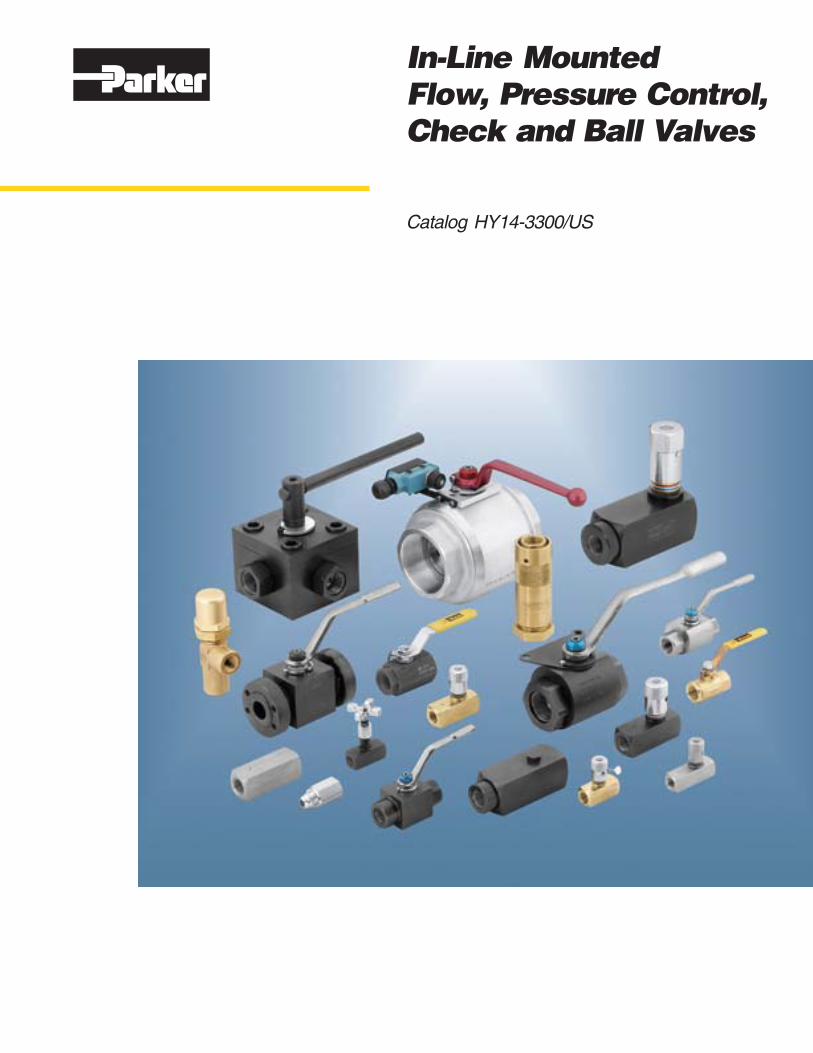
Catalog HY14-3300/US
In-Line MountedFlow, Pressure Control,Check and Ball Valves
II Parker Hannifin CorporationHydraulic Valve DivisionElyria, Ohio, USA
FAILURE OR IMPROPER SELECTION OR IMPROPER USE OF THE PRODUCTS AND/OR SYSTEMS DESCRIBED HEREIN OR RELATED ITEMS CAN CAUSE DEATH,PERSONAL INJURY AND PROPERTY DAMAGE.
This document and other information from Parker Hannifin Corporation, its subsidiaries and authorized distributors provide product and/or system options for further investigation byusers having technical expertise. It is important that you analyze all aspects of your application and review the information concerning the product or system in the current productcatalog. Due to the variety of operating conditions and applications for these products or systems, the user, through its own analysis and testing, is solely responsible for making thefinal selection of the products and systems and assuring that all performance, safety and warning requirements of the application are met.
The products described herein, including without limitation, product features, specifications, designs, availability and pricing, are subject to change by Parker Hannifin Corporationand its subsidiaries at any time without notice.
WARNING
The items described in this document are hereby offered for sale by Parker Hannifin Corporation, its subsidiaries or its authorized distributors. This offer and its acceptance are governedby the provisions stated in the "Offer of Sale".
© Copyright 2006, 1999 Parker Hannifin Corporation, All Rights Reserved
Offer of Sale
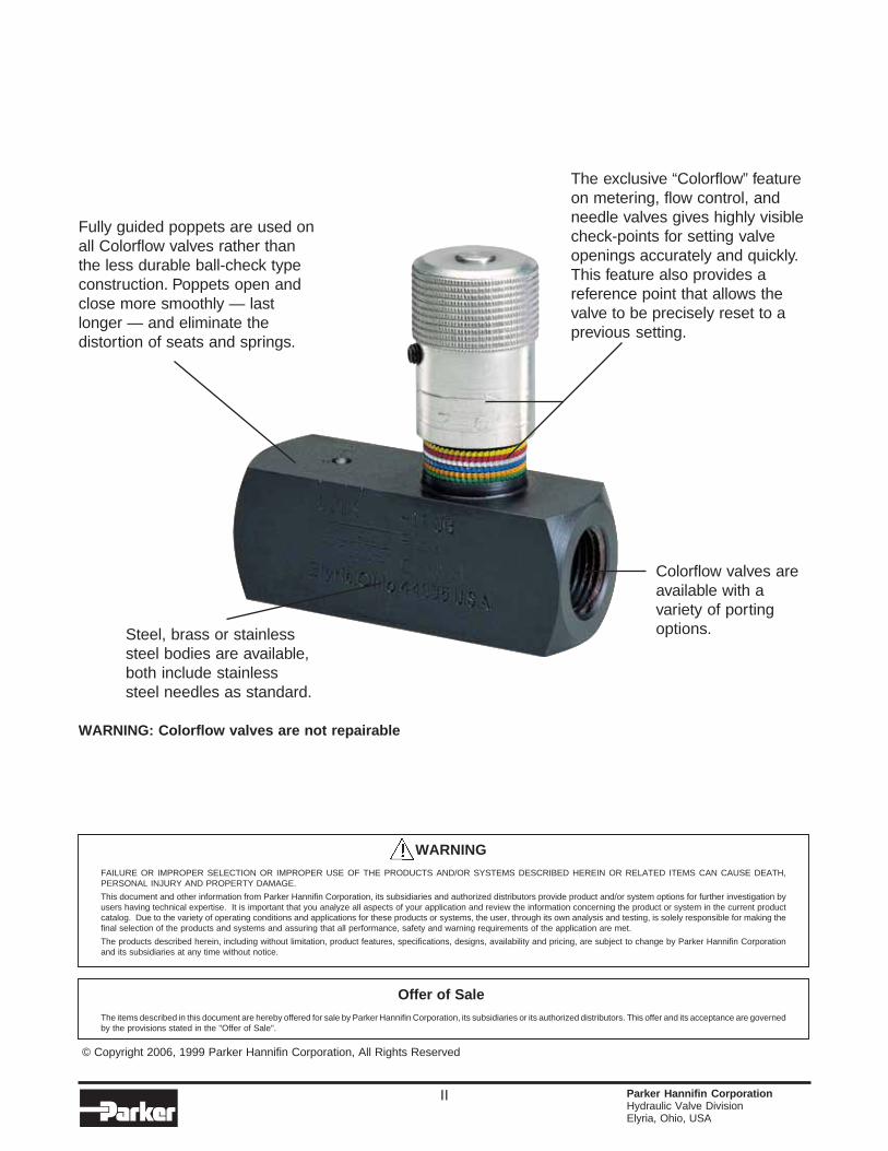
Fully guided poppets are used onall Colorflow valves rather thanthe less durable ball-check typeconstruction. Poppets open andclose more smoothly — lastlonger — and eliminate thedistortion of seats and springs.
Steel, brass or stainlesssteel bodies are available,both include stainlesssteel needles as standard.
The exclusive “Colorflow” featureon metering, flow control, andneedle valves gives highly visiblecheck-points for setting valveopenings accurately and quickly.This feature also provides areference point that allows thevalve to be precisely reset to aprevious setting.
Colorflow valves areavailable with avariety of portingoptions.
WARNING: Colorflow valves are not repairable
3300-intro.p65, dd
III Parker Hannifin CorporationHydraulic Valve DivisionElyria, Ohio, USA
Actuation and speed of response of fluid power systems on any type of industrialequipment can be controlled precisely, instantly, and repeatedly with Parker ControlValves.
The Colorflow line includes flow control valves rated from 0 to 568 LPM (0 to 150 GPM),needle valves from 0 to 265 LPM (0 to 70 GPM), and for very accurate control, themetering valves provide linear adjustment of flows from 0 to 151 LPM (0 to 40 GPM).
Fast actuation and deceleration…precise control of fluid power…protection for fluidpower systems against back-pressure and vibration…accurate settings for fluid valvesand controls…
These are a few functions that the complete line of Parker Hydraulic and PneumaticControl Valves are filling on all kinds of machinery and equipment around the world.
Engineered to top design, built to top quality standards, these are the finest, mostaccurate controls you can install on your machines. Features include the exclusive“Colorflow” color-coded system that gives operators a visual checkpoint in setting valvesprecisely. And the use of quality materials and components in bodies assure a controlvalve that withstands shock, vibration and wear, and has extraordinary life expectancy.
Why we use poppets exclusively.
Poppets are used in all Colorflow Valves, instead of check balls. As the poppets areopened and closed, they move in precision-fitted cylinders that eliminate wobble anderratic travel.
Poppets also have hydraulic cushioning to soften the impact of the poppet againstthe valve spring and seat at the end of travel. By contrast, check balls (not used byColorflow) have large mass that develops heavy impact on the seat and causes thespring to bottom. These hammer blows can peen the seat, roughen the ball, andeventually create a leaker. Springs that are bottomed frequently are susceptible toearly fatigue and failure. Worn balls can develop chatter; and may shift position andnot shut off tightly.
Balls cannot be decelerated at the end of their travel in the way poppets are slowed byhydraulic bleeding ports and channels.
A worldwide organization of well-stocked Parker Colorflow distributors means immediatedelivery of any control valve in our line of top-quality products to control air and oil onany fluid-power system.
Provide a Visual Check of Precise Valve SettingsColorflow® Needle, Flow and Check Valves
Catalog HY14-3300/US
3300-intro.p65, dd
IV Parker Hannifin CorporationHydraulic Valve DivisionElyria, Ohio, USA
H
ContentsFlow, Pressure Control, Check and Ball Valves
In-Line Mounted Valves Page
Flow Control Valves
Series F .............................................. Flow Controls .................................................................................. 1 - 4
Series 6F ............................................ Flow Controls (Metric Ports) ........................................................... 5 - 6
Series PC*K ........................................ Pressure Compensated Flow Controls ........................................... 7 - 9
Series PC*M ....................................... Pressure Compensated Flow Controls, Adjustable .................... 10 - 12
Series N .............................................. Needle Valves ............................................................................. 13 - 15
Series 6N ............................................ Needle Valves (Metric Ports) ....................................................... 16 - 17
Series MV ........................................... Metering Valves ........................................................................... 18 - 21
Series 6MV ......................................... Metering Valves (Metric Ports) .................................................... 22 - 23
Series MFB ......................................... Flow Control Valves ..................................................................... 24 - 25
Check Valves
Series AVF .......................................... Hydraulic Adjustable Velocity Fuse ............................................. 26 - 28
Series AVF .......................................... Pneumatic Adjustable Velocity Fuse ........................................... 29 - 30
Series VLS .......................................... Fixed Velocity Fuse ..................................................................... 31 - 33
Series C .............................................. Check Valves ............................................................................... 34 - 36
Series 6C ............................................ Check Valves (Metric Ports) ........................................................ 37 - 38
Series VCL .......................................... Check Valves ............................................................................... 39 - 42
Series CLS.......................................... Check Valves ............................................................................... 43 - 44
Series LT, LTF ..................................... Check Valves ............................................................................... 45 - 46
Pressure Control Valves
Series 620 - 649 ....................................................................................................................................... 47 - 49
Accessories
Series GF............................................ Pressure Snubbers ........................................................................... 50
Series GT............................................ Gage Isolator Valves .......................................................................... 51
High Pressure Ball Valves
Introduction ...................................................................................................................................................... 52
Series BVHP ......................... 2-Way, 414 Bar (6000 PSI) ................. 1/4"-1", steel ................................ 53 - 60
Series BVAH ......................... 2-Way, 414 Bar (6000 PSI) ................. 1 1/4"-2", steel ............................. 61 - 68
Series BVHH ........................ 2-Way, 690 Bar (10,000 PSI) .............. 1/2"-2", steel ................................ 69 - 72
Series BVAM......................... 2-Way, 138 Bar (2000 PSI) ................. 1/2"-4", steel ................................ 73 - 76
Series BV3D ......................... 3-Way, 207 Bar (3000 PSI) ................. 1/4"-2", steel ................................ 77 - 81
Series BV3H, BV4H.............. 3 and 4-Way, 414 Bar (6000 PSI) ....... 1/4"-2", steel ................................ 82 - 86
Series BVMM ........................ 2 and 3-Way, 414 Bar (6000 PSI) ....... 1/4"-2", steel-manifold ................. 87 - 92
Series BVAL .......................... 2-Way, 28 Bar (400 PSI) ..................... 1/4"-4", aluminum-suction ........... 93 - 96
Technical Appendix ................................................................................................................................... 97 - 98
Low Pressure Ball Valves
Introduction ...................................................................................................................................................... 99
Series 500............................. 2-Way, 41 Bar (600 PSI) ..................... 1/4"-2", brass ........................... 100 - 110
Series 520............................. 2-Way, 41 Bar (600 PSI) ..................... 1/4" - 3" brass.......................... 111 - 112
Series 500CS ....................... 2-Way, 138 Bar (2000 PSI) ................. 1/4"-1", steel ............................ 113 - 116
Series 50*SS ........................ 2-Way, 138 Bar (2000 PSI) ................. 1/4"-1", stainless steel ............. 117 - 120
Series 590............................. 2-Way, 17 Bar (250 PSI) ..................... 1/4"-1/2", brass-right angle ..... 121 - 123
Offer of Sale ......................................................................................................................................................... 124
Catalog HY14-3300/US
3300-1.p65, dd
1 Parker Hannifin CorporationHydraulic Valve DivisionElyria, Ohio, USA
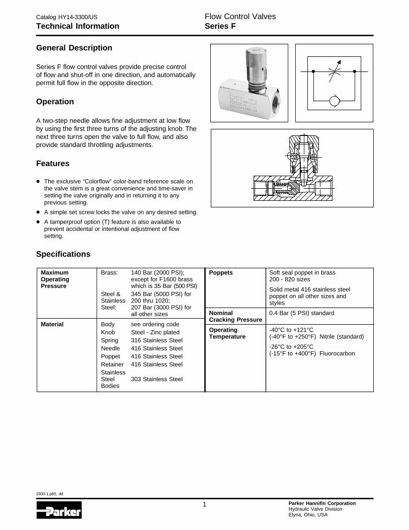
General Description
Series F flow control valves provide precise controlof flow and shut-off in one direction, and automaticallypermit full flow in the opposite direction.
Operation
A two-step needle allows fine adjustment at low flowby using the first three turns of the adjusting knob. Thenext three turns open the valve to full flow, and alsoprovide standard throttling adjustments.
Features
• The exclusive “Colorflow” color-band reference scale onthe valve stem is a great convenience and time-saver insetting the valve originally and in returning it to anyprevious setting.
• A simple set screw locks the valve on any desired setting.
• A tamperproof option (T) feature is also available toprevent accidental or intentional adjustment of flowsetting.
Specifications
Technical InformationFlow Control ValvesSeries F
Maximum Brass: 140 Bar (2000 PSI);Operating except for F1600 brassPressure which is 35 Bar (500 PSI)
Steel & 345 Bar (5000 PSI) forStainless 200 thru 1020;Steel: 207 Bar (3000 PSI) for
all other sizes
Material Body see ordering codeKnob Steel - Zinc platedSpring 316 Stainless SteelNeedle 416 Stainless SteelPoppet 416 Stainless SteelRetainer 416 Stainless SteelStainlessSteel 303 Stainless SteelBodies
Poppets Soft seal poppet in brass200 - 820 sizes
Solid metal 416 stainless steelpoppet on all other sizes andstyles
Nominal 0.4 Bar (5 PSI) standardCracking Pressure
Operating -40°C to +121°CTemperature (-40°F to +250°F) Nitrile (standard)
-26°C to +205°C(-15°F to +400°F) Fluorocarbon
Catalog HY14-3300/US
3300-1.p65, dd
2 Parker Hannifin CorporationHydraulic Valve DivisionElyria, Ohio, USA
H
Code Description
Omit Standard
4 Fine Metering(200, 400, 600,620, 820 sizes)
Code Description
B Brass
S Steel
SS* Stainless SteelSeries F Brass Valves canbe used for both air and oilservice.
* Available in 400, 600 and800 sizes.
Code Description
Omit Nitrile (Standard)
V Fluorocarbon
Code Description
Omit NPTF/SAE
★8 BSPT
★★9 BSPP
FOptions Series Size Material Needle
OptionsOther
OptionsSeal
CompoundDesignSeriesNOTE:
Not requiredwhen ordering.
* Not available above1200 size.
Code Description
Omit Standard Knob
T * Tamperproof
F Finger Screw
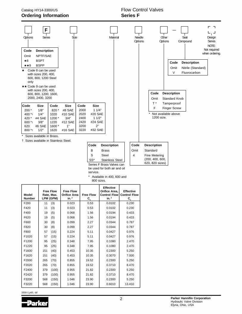
Ordering InformationFlow Control ValvesSeries F
200 * 1/8"400 *† 1/4"420 * #4 SAE600 *† 3/8"620 #6 SAE800 *† 1/2"
820 * #8 SAE1020 #10 SAE1200 * 3/4"1220 #12 SAE1600 * 1"1620 #16 SAE
2000 1 1/4"2020 #20 SAE2400 1 1/2"2420 #24 SAE3200 2"3220 #32 SAE
* Sizes available in Brass.
† Sizes available in Stainless Steel.
Code Size Code Size Code Size
EffectiveFree Flow Free Flow Orifice Area, Effective
Model Rate, Max. Orifice Area Free Flow Control Flow Control FlowNumber LPM (GPM) in. 2 Cv in. 2 Cv
F200 11 (3) 0.023 0.53 0.0102 0.230
F420 11 (3) 0.023 0.53 0.0102 0.230
F400 19 (5) 0.068 1.56 0.0194 0.433
F620 19 (5) 0.068 1.56 0.0194 0.433
F600 30 (8) 0.099 2.27 0.0344 0.787
F820 30 (8) 0.099 2.27 0.0344 0.787
F800 57 (15) 0.224 5.11 0.0427 0.976
F1020 57 (15) 0.224 5.11 0.0427 0.976
F1200 95 (25) 0.348 7.95 0.1080 2.470
F1220 95 (25) 0.348 7.95 0.1080 2.470
F1600 151 (40) 0.453 10.35 0.2300 5.250
F1620 151 (40) 0.453 10.35 0.3070 7.000
F2000 265 (70) 0.855 19.52 0.2300 5.250
F2020 265 (70) 0.855 19.52 0.3710 8.470
F2400 379 (100) 0.955 21.82 0.2300 5.250
F2420 379 (100) 0.955 21.82 0.3710 8.470
F3200 568 (150) 1.046 23.90 0.2300 5.250
F3220 568 (150) 1.046 23.90 0.6010 13.410
★ Code 8 can be usedwith sizes 200, 400,600, 800, 1200 Steelonly
★★ Code 9 can be usedwith sizes 200, 400,600, 800, 1200, 1600,2000, 2400, 3200
Catalog HY14-3300/US
3300-1.p65, dd
3 Parker Hannifin CorporationHydraulic Valve DivisionElyria, Ohio, USA
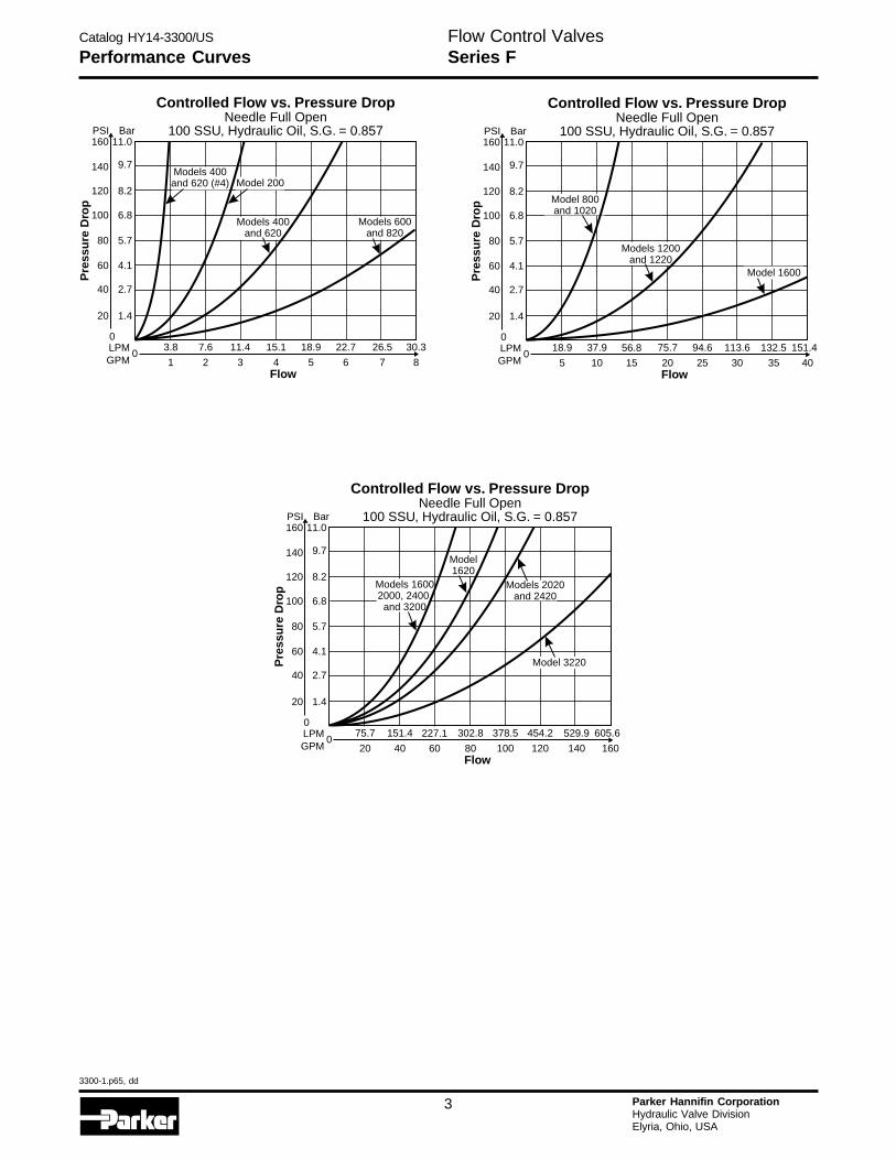
Performance Curves
Controlled Flow vs. Pressure DropNeedle Full Open
100 SSU, Hydraulic Oil, S.G. = 0.857
015.1 18.9 22.711.4
4 5 63
26.5 30.3
7 8
7.63.8
21Flow
Pre
ssu
re D
rop
LPMGPM
0
20 1.4
40 2.7
60 4.1
100
120
80
6.8
8.2
5.7
140
160PSI
9.7
11.0Bar
Models 400and 620 (#4)
Models 600and 820
Models 400and 620
Model 200
Controlled Flow vs. Pressure DropNeedle Full Open
100 SSU, Hydraulic Oil, S.G. = 0.857
075.7 94.6 113.656.8
20 25 3015
132.5 151.4
35 40
37.918.9
105Flow
Pre
ssu
re D
rop
LPMGPM
0
20 1.4
40 2.7
60 4.1
100
120
80
6.8
8.2
5.7
140
160PSI
9.7
11.0Bar
Model 1600
Model 800and 1020
Models 1200and 1220
Controlled Flow vs. Pressure DropNeedle Full Open
100 SSU, Hydraulic Oil, S.G. = 0.857
0302.8 378.5 454.2227.1
80 100 12060
529.9 605.6
140 160
151.475.7
4020Flow
Pre
ssu
re D
rop
LPMGPM
0
20 1.4
40 2.7
60 4.1
100
120
80
6.8
8.2
5.7
140
160PSI
9.7
11.0Bar
Models 2020and 2420
Model 3220
Model1620
Models 16002000, 2400,and 3200
Flow Control ValvesSeries F
Catalog HY14-3300/US
3300-1.p65, dd
4 Parker Hannifin CorporationHydraulic Valve DivisionElyria, Ohio, USA
H
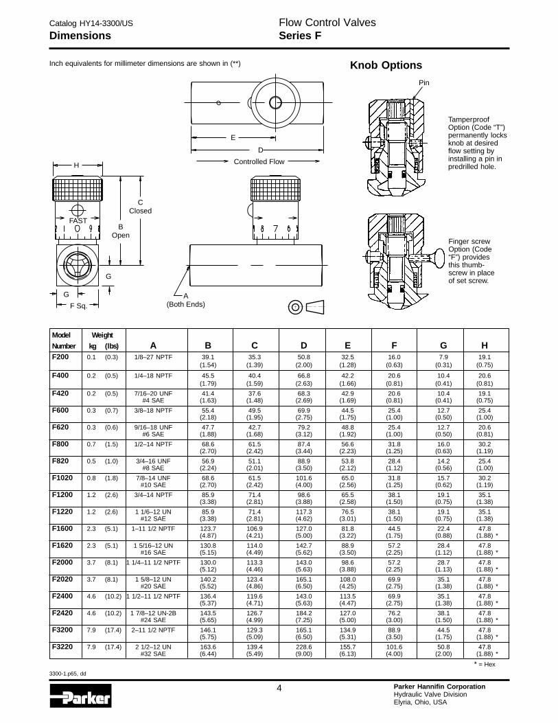
Inch equivalents for millimeter dimensions are shown in (**)
H
E
D
CClosed
BOpen
G
F Sq.A
(Both Ends)G
FAST
Controlled Flow
Knob Options
Pin
TamperproofOption (Code “T”)permanently locksknob at desiredflow setting byinstalling a pin inpredrilled hole.
Finger screwOption (Code“F”) providesthis thumb-screw in placeof set screw.
DimensionsFlow Control ValvesSeries F
Model WeightNumber kg (lbs) A B C D E F G HF200 0.1 (0.3) 1/8–27 NPTF 39.1 35.3 50.8 32.5 16.0 7.9 19.1
(1.54) (1.39) (2.00) (1.28) (0.63) (0.31) (0.75)
F400 0.2 (0.5) 1/4–18 NPTF 45.5 40.4 66.8 42.2 20.6 10.4 20.6(1.79) (1.59) (2.63) (1.66) (0.81) (0.41) (0.81)
F420 0.2 (0.5) 7/16–20 UNF 41.4 37.6 68.3 42.9 20.6 10.4 19.1#4 SAE (1.63) (1.48) (2.69) (1.69) (0.81) (0.41) (0.75)
F600 0.3 (0.7) 3/8–18 NPTF 55.4 49.5 69.9 44.5 25.4 12.7 25.4(2.18) (1.95) (2.75) (1.75) (1.00) (0.50) (1.00)
F620 0.3 (0.6) 9/16–18 UNF 47.7 42.7 79.2 48.8 25.4 12.7 20.6#6 SAE (1.88) (1.68) (3.12) (1.92) (1.00) (0.50) (0.81)
F800 0.7 (1.5) 1/2–14 NPTF 68.6 61.5 87.4 56.6 31.8 16.0 30.2(2.70) (2.42) (3.44) (2.23) (1.25) (0.63) (1.19)
F820 0.5 (1.0) 3/4–16 UNF 56.9 51.1 88.9 53.8 28.4 14.2 25.4#8 SAE (2.24) (2.01) (3.50) (2.12) (1.12) (0.56) (1.00)
F1020 0.8 (1.8) 7/8–14 UNF 68.6 61.5 101.6 65.0 31.8 15.7 30.2#10 SAE (2.70) (2.42) (4.00) (2.56) (1.25) (0.62) (1.19)
F1200 1.2 (2.6) 3/4–14 NPTF 85.9 71.4 98.6 65.5 38.1 19.1 35.1(3.38) (2.81) (3.88) (2.58) (1.50) (0.75) (1.38)
F1220 1.2 (2.6) 1 1/6–12 UN 85.9 71.4 117.3 76.5 38.1 19.1 35.1#12 SAE (3.38) (2.81) (4.62) (3.01) (1.50) (0.75) (1.38)
F1600 2.3 (5.1) 1–11 1/2 NPTF 123.7 106.9 127.0 81.8 44.5 22.4 47.8(4.87) (4.21) (5.00) (3.22) (1.75) (0.88) (1.88) *
F1620 2.3 (5.1) 1 5/16–12 UN 130.8 114.0 142.7 88.9 57.2 28.4 47.8#16 SAE (5.15) (4.49) (5.62) (3.50) (2.25) (1.12) (1.88) *
F2000 3.7 (8.1) 1 1/4–11 1/2 NPTF 130.0 113.3 143.0 98.6 57.2 28.7 47.8(5.12) (4.46) (5.63) (3.88) (2.25) (1.13) (1.88) *
F2020 3.7 (8.1) 1 5/8–12 UN 140.2 123.4 165.1 108.0 69.9 35.1 47.8#20 SAE (5.52) (4.86) (6.50) (4.25) (2.75) (1.38) (1.88) *
F2400 4.6 (10.2) 1 1/2–11 1/2 NPTF 136.4 119.6 143.0 113.5 69.9 35.1 47.8(5.37) (4.71) (5.63) (4.47) (2.75) (1.38) (1.88) *
F2420 4.6 (10.2) 1 7/8–12 UN-2B 143.5 126.7 184.2 127.0 76.2 38.1 47.8#24 SAE (5.65) (4.99) (7.25) (5.00) (3.00) (1.50) (1.88) *
F3200 7.9 (17.4) 2–11 1/2 NPTF 146.1 129.3 165.1 134.9 88.9 44.5 47.8(5.75) (5.09) (6.50) (5.31) (3.50) (1.75) (1.88) *
F3220 7.9 (17.4) 2 1/2–12 UN 163.6 139.4 228.6 155.7 101.6 50.8 47.8#32 SAE (6.44) (5.49) (9.00) (6.13) (4.00) (2.00) (1.88) *
* = Hex
Catalog HY14-3300/US
3300-1.p65, dd
5 Parker Hannifin CorporationHydraulic Valve DivisionElyria, Ohio, USA
Technical Information
General Description
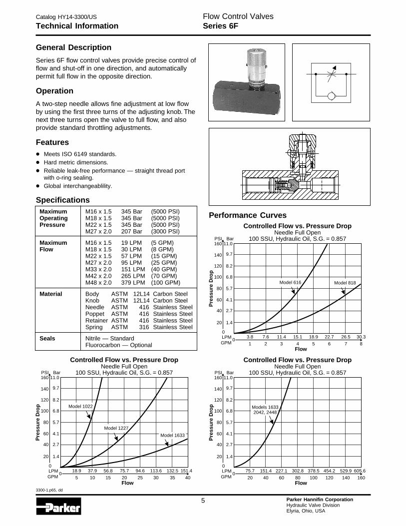
Series 6F flow control valves provide precise control offlow and shut-off in one direction, and automaticallypermit full flow in the opposite direction.
Operation
A two-step needle allows fine adjustment at low flowby using the first three turns of the adjusting knob. Thenext three turns open the valve to full flow, and alsoprovide standard throttling adjustments.
Features
• Meets ISO 6149 standards.
• Hard metric dimensions.
• Reliable leak-free performance — straight thread portwith o-ring sealing.
• Global interchangeablility.
SpecificationsMaximum M16 x 1.5 345 Bar (5000 PSI)Operating M18 x 1.5 345 Bar (5000 PSI)Pressure M22 x 1.5 345 Bar (5000 PSI)
M27 x 2.0 207 Bar (3000 PSI)
Maximum M16 x 1.5 19 LPM (5 GPM)Flow M18 x 1.5 30 LPM (8 GPM)
M22 x 1.5 57 LPM (15 GPM)M27 x 2.0 95 LPM (25 GPM)M33 x 2.0 151 LPM (40 GPM)M42 x 2.0 265 LPM (70 GPM)M48 x 2.0 379 LPM (100 GPM)
Material Body ASTM 12L14 Carbon SteelKnob ASTM 12L14 Carbon SteelNeedle ASTM 416 Stainless SteelPoppet ASTM 416 Stainless SteelRetainer ASTM 416 Stainless SteelSpring ASTM 316 Stainless Steel
Seals Nitrile — StandardFluorocarbon — Optional
Controlled Flow vs. Pressure DropNeedle Full Open
100 SSU, Hydraulic Oil, S.G. = 0.857
075.7 94.6 113.656.8
20 25 3015
132.5 151.4
35 40
37.918.9
105Flow
Pre
ssu
re D
rop
LPMGPM
0
20 1.4
40 2.7
60 4.1
100
120
80
6.8
8.2
5.7
140
160PSI
9.7
11.0Bar
Model 1633
Model 1022
Model 1227
Controlled Flow vs. Pressure DropNeedle Full Open
100 SSU, Hydraulic Oil, S.G. = 0.857
0302.8 378.5 454.2227.1
80 100 12060
529.9 605.6
140 160
151.475.7
4020Flow
Pre
ssu
re D
rop
LPMGPM
0
20 1.4
40 2.7
60 4.1
100
120
80
6.8
8.2
5.7
140
160PSI
9.7
11.0Bar
Models 16332042, 2448
Performance CurvesControlled Flow vs. Pressure Drop
Needle Full Open100 SSU, Hydraulic Oil, S.G. = 0.857
015.1 18.9 22.711.4
4 5 63
26.5 30.3
7 8
7.63.8
21Flow
Pre
ssu
re D
rop
LPMGPM
0
20 1.4
40 2.7
60 4.1
100
120
80
6.8
8.2
5.7
140
160PSI
9.7
11.0Bar
Model 818Model 616
Flow Control ValvesSeries 6F
Catalog HY14-3300/US
3300-1.p65, dd
6 Parker Hannifin CorporationHydraulic Valve DivisionElyria, Ohio, USA
H
Technical Information
Ports Style Material DesignSeriesNOTE:
Not requiredwhen ordering.
6 FSize
S
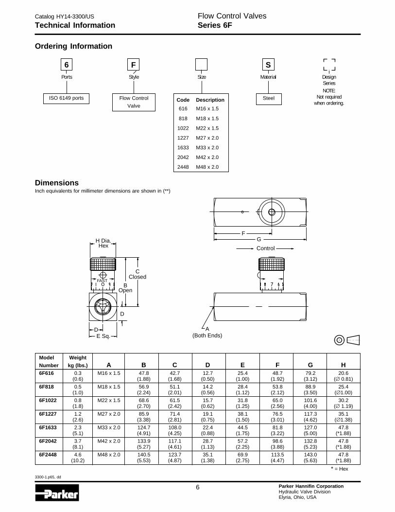
DimensionsInch equivalents for millimeter dimensions are shown in (**)
Model Weight
Number kg (lbs.) A B C D E F G H6F616 0.3 M16 x 1.5 47.8 42.7 12.7 25.4 48.7 79.2 20.6
(0.6) (1.88) (1.68) (0.50) (1.00) (1.92) (3.12) (∅ 0.81)
6F818 0.5 M18 x 1.5 56.9 51.1 14.2 28.4 53.8 88.9 25.4(1.0) (2.24) (2.01) (0.56) (1.12) (2.12) (3.50) (∅1.00)
6F1022 0.8 M22 x 1.5 68.6 61.5 15.7 31.8 65.0 101.6 30.2(1.8) (2.70) (2.42) (0.62) (1.25) (2.56) (4.00) (∅ 1.19)
6F1227 1.2 M27 x 2.0 85.9 71.4 19.1 38.1 76.5 117.3 35.1(2.6) (3.38) (2.81) (0.75) (1.50) (3.01) (4.62) (∅1.38)
6F1633 2.3 M33 x 2.0 124.7 108.0 22.4 44.5 81.8 127.0 47.8(5.1) (4.91) (4.25) (0.88) (1.75) (3.22) (5.00) (*1.88)
6F2042 3.7 M42 x 2.0 133.9 117.1 28.7 57.2 98.6 132.8 47.8(8.1) (5.27) (4.61) (1.13) (2.25) (3.88) (5.23) (*1.88)
6F2448 4.6 M48 x 2.0 140.5 123.7 35.1 69.9 113.5 143.0 47.8(10.2) (5.53) (4.87) (1.38) (2.75) (4.47) (5.63) (*1.88)
* = Hex
ISO 6149 ports Flow Control
Valve
SteelCode Description
616 M16 x 1.5
818 M18 x 1.5
1022 M22 x 1.5
1227 M27 x 2.0
1633 M33 x 2.0
2042 M42 x 2.0
2448 M48 x 2.0
Flow Control ValvesSeries 6F
H Dia.Hex Control
FG
CClosed
BOpen
D
E Sq.A
(Both Ends)D
FAST
Ordering Information
Catalog HY14-3300/US
3300-1.p65, dd
7 Parker Hannifin CorporationHydraulic Valve DivisionElyria, Ohio, USA
General Description
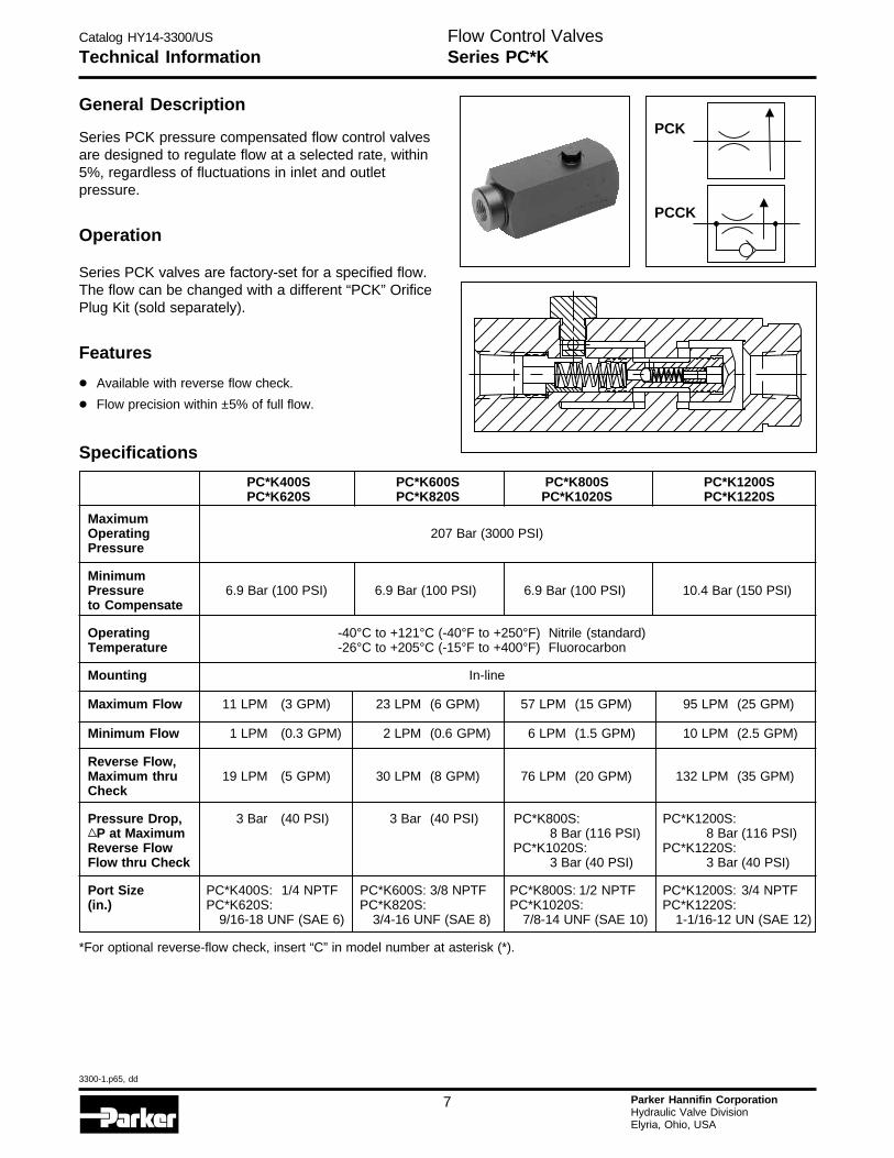
Series PCK pressure compensated flow control valvesare designed to regulate flow at a selected rate, within5%, regardless of fluctuations in inlet and outletpressure.
Operation
Series PCK valves are factory-set for a specified flow.The flow can be changed with a different “PCK” OrificePlug Kit (sold separately).
Features
• Available with reverse flow check.
• Flow precision within ±5% of full flow.
Technical Information
PC*K400S PC*K600S PC*K800S PC*K1200SPC*K620S PC*K820S PC*K1020S PC*K1220S
MaximumOperating 207 Bar (3000 PSI)Pressure
MinimumPressure 6.9 Bar (100 PSI) 6.9 Bar (100 PSI) 6.9 Bar (100 PSI) 10.4 Bar (150 PSI)to Compensate
Operating -40°C to +121°C (-40°F to +250°F) Nitrile (standard)Temperature -26°C to +205°C (-15°F to +400°F) Fluorocarbon
Mounting In-line
Maximum Flow 11 LPM (3 GPM) 23 LPM (6 GPM) 57 LPM (15 GPM) 95 LPM (25 GPM)
Minimum Flow 1 LPM (0.3 GPM) 2 LPM (0.6 GPM) 6 LPM (1.5 GPM) 10 LPM (2.5 GPM)
Reverse Flow,Maximum thru 19 LPM (5 GPM) 30 LPM (8 GPM) 76 LPM (20 GPM) 132 LPM (35 GPM)Check
Pressure Drop, 3 Bar (40 PSI) 3 Bar (40 PSI) PC*K800S: PC*K1200S:P at Maximum 8 Bar (116 PSI) 8 Bar (116 PSI)
Reverse Flow PC*K1020S: PC*K1220S:Flow thru Check 3 Bar (40 PSI) 3 Bar (40 PSI)
Port Size PC*K400S: 1/4 NPTF PC*K600S: 3/8 NPTF PC*K800S: 1/2 NPTF PC*K1200S: 3/4 NPTF(in.) PC*K620S: PC*K820S: PC*K1020S: PC*K1220S:
9/16-18 UNF (SAE 6) 3/4-16 UNF (SAE 8) 7/8-14 UNF (SAE 10) 1-1/16-12 UN (SAE 12)
*For optional reverse-flow check, insert “C” in model number at asterisk (*).
PCK
PCCK
Specifications
Flow Control ValvesSeries PC*K
Catalog HY14-3300/US
3300-1.p65, dd
8 Parker Hannifin CorporationHydraulic Valve DivisionElyria, Ohio, USA
H
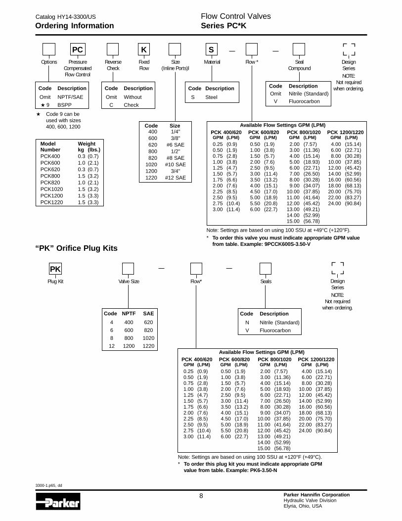
Ordering Information
Code Description
Omit Without
C Check
Available Flow Settings GPM (LPM)PCK 400/620 PCK 600/820 PCK 800/1020 PCK 1200/1220GPM (LPM) GPM (LPM) GPM (LPM) GPM (LPM)0.25 (0.9) 0.50 (1.9) 2.00 (7.57) 4.00 (15.14)0.50 (1.9) 1.00 (3.8) 3.00 (11.36) 6.00 (22.71)0.75 (2.8) 1.50 (5.7) 4.00 (15.14) 8.00 (30.28)1.00 (3.8) 2.00 (7.6) 5.00 (18.93) 10.00 (37.85)1.25 (4.7) 2.50 (9.5) 6.00 (22.71) 12.00 (45.42)1.50 (5.7) 3.00 (11.4) 7.00 (26.50) 14.00 (52.99)1.75 (6.6) 3.50 (13.2) 8.00 (30.28) 16.00 (60.56)2.00 (7.6) 4.00 (15.1) 9.00 (34.07) 18.00 (68.13)2.25 (8.5) 4.50 (17.0) 10.00 (37.85) 20.00 (75.70)2.50 (9.5) 5.00 (18.9) 11.00 (41.64) 22.00 (83.27)2.75 (10.4) 5.50 (20.8) 12.00 (45.42) 24.00 (90.84)3.00 (11.4) 6.00 (22.7) 13.00 (49.21)
14.00 (52.99)15.00 (56.78)
Code NPTF SAE
4 400 620
6 600 820
8 800 1020
12 1200 1220
“PK” Orifice Plug Kits
Model WeightNumber kg (lbs.)PCK400 0.3 (0.7)PCK600 1.0 (2.1)PCK620 0.3 (0.7)PCK800 1.5 (3.2)PCK820 1.0 (2.1)PCK1020 1.5 (3.2)PCK1200 1.5 (3.3)PCK1220 1.5 (3.3)
Code Description
N Nitrile (Standard)
V Fluorocarbon
DesignSeriesNOTE:
Not requiredwhen ordering.
Plug Kit Valve Size Flow* Seals
PK
DesignSeriesNOTE:
Not requiredwhen ordering.
Options ReverseCheck
FixedFlow
Size(Inline Ports)l
Material SealCompound
K SFlow *Pressure
CompensatedFlow Control
PC
Code Description
Omit NPTF/SAE
★ 9 BSPP
Code Description
S Steel
Code DescriptionOmit Nitrile (Standard)
V Fluorocarbon
Available Flow Settings GPM (LPM)PCK 400/620 PCK 600/820 PCK 800/1020 PCK 1200/1220GPM (LPM) GPM (LPM) GPM (LPM) GPM (LPM)0.25 (0.9) 0.50 (1.9) 2.00 (7.57) 4.00 (15.14)0.50 (1.9) 1.00 (3.8) 3.00 (11.36) 6.00 (22.71)0.75 (2.8) 1.50 (5.7) 4.00 (15.14) 8.00 (30.28)1.00 (3.8) 2.00 (7.6) 5.00 (18.93) 10.00 (37.85)1.25 (4.7) 2.50 (9.5) 6.00 (22.71) 12.00 (45.42)1.50 (5.7) 3.00 (11.4) 7.00 (26.50) 14.00 (52.99)1.75 (6.6) 3.50 (13.2) 8.00 (30.28) 16.00 (60.56)2.00 (7.6) 4.00 (15.1) 9.00 (34.07) 18.00 (68.13)2.25 (8.5) 4.50 (17.0) 10.00 (37.85) 20.00 (75.70)2.50 (9.5) 5.00 (18.9) 11.00 (41.64) 22.00 (83.27)2.75 (10.4) 5.50 (20.8) 12.00 (45.42) 24.00 (90.84)3.00 (11.4) 6.00 (22.7) 13.00 (49.21)
14.00 (52.99)15.00 (56.78)
Note: Settings are based on using 100 SSU at +49°C (+120°F).
* To order this valve you must indicate appropriate GPM valuefrom table. Example: 9PCCK600S-3.50-V
Flow Control ValvesSeries PC*K
400 1/4"600 3/8"620 #6 SAE800 1/2"820 #8 SAE
1020 #10 SAE1200 3/4"1220 #12 SAE
Code Size
Note: Settings are based on using 100 SSU at +120°F (+49°C).* To order this plug kit you must indicate appropriate GPM
value from table. Example: PK6-3.50-N
★ Code 9 can beused with sizes400, 600, 1200
Catalog HY14-3300/US
3300-1.p65, dd
9 Parker Hannifin CorporationHydraulic Valve DivisionElyria, Ohio, USA
Technical Information
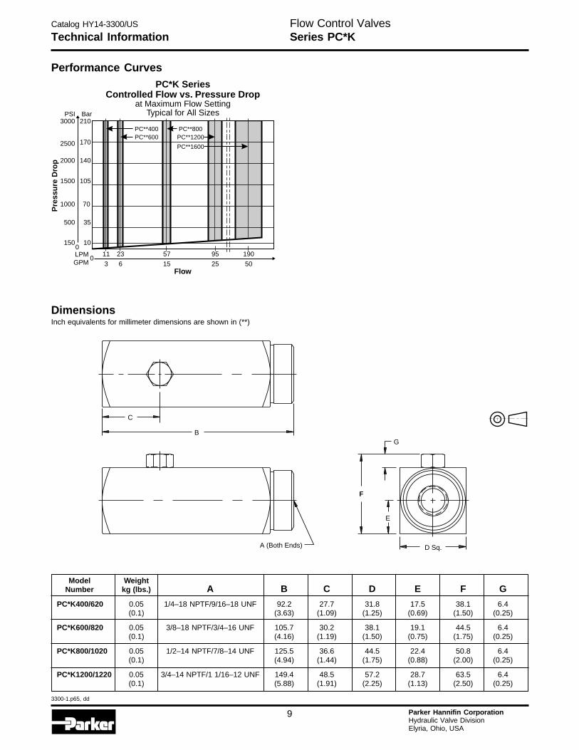
Performance Curves
DimensionsInch equivalents for millimeter dimensions are shown in (**)
Model WeightNumber kg (lbs.) A B C D E F G
PC*K400/620 0.05 1/4–18 NPTF/9/16–18 UNF 92.2 27.7 31.8 17.5 38.1 6.4(0.1) (3.63) (1.09) (1.25) (0.69) (1.50) (0.25)
PC*K600/820 0.05 3/8–18 NPTF/3/4–16 UNF 105.7 30.2 38.1 19.1 44.5 6.4(0.1) (4.16) (1.19) (1.50) (0.75) (1.75) (0.25)
PC*K800/1020 0.05 1/2–14 NPTF/7/8–14 UNF 125.5 36.6 44.5 22.4 50.8 6.4(0.1) (4.94) (1.44) (1.75) (0.88) (2.00) (0.25)
PC*K1200/1220 0.05 3/4–14 NPTF/1 1/16–12 UNF 149.4 48.5 57.2 28.7 63.5 6.4(0.1) (5.88) (1.91) (2.25) (1.13) (2.50) (0.25)
B
F
E
D Sq.A (Both Ends)
G
C
PC*K SeriesControlled Flow vs. Pressure Drop
at Maximum Flow SettingTypical for All Sizes
095 190572311
Pre
ssu
re D
rop
LPMGPM
0150 10
500 35
1500
2000
1000
105
140
70
2500
3000PSI
170
210Bar
PC**400 PC**800PC**600 PC**1200
PC**1600
25 501563Flow
Flow Control ValvesSeries PC*K
Catalog HY14-3300/US
3300-1.p65, dd
10 Parker Hannifin CorporationHydraulic Valve DivisionElyria, Ohio, USA
H
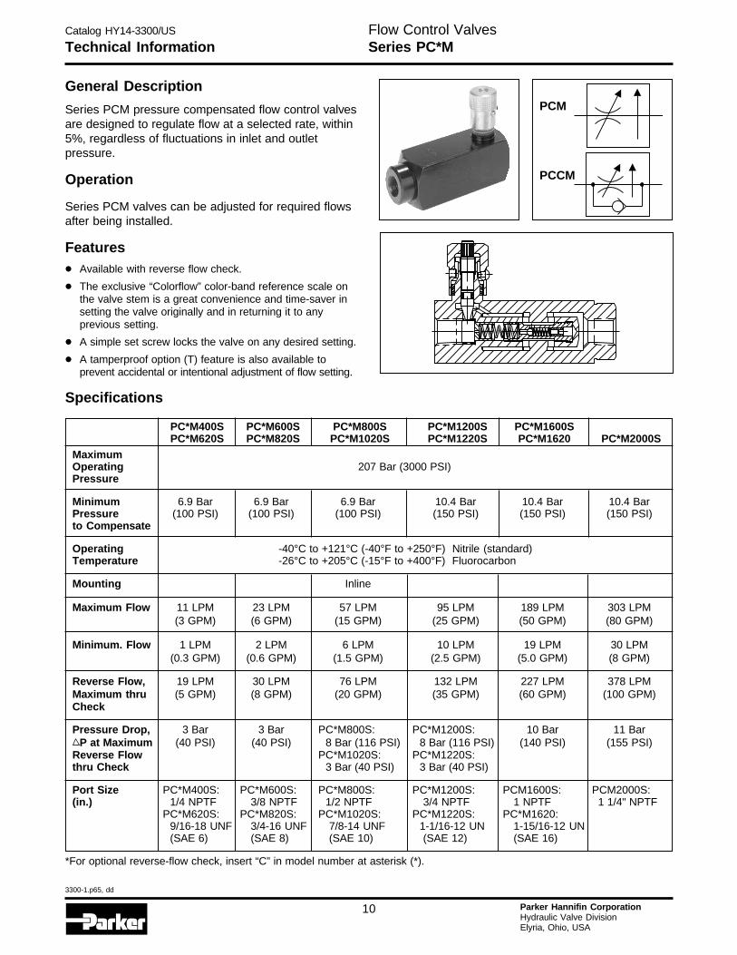
General Description
Series PCM pressure compensated flow control valvesare designed to regulate flow at a selected rate, within5%, regardless of fluctuations in inlet and outletpressure.
Operation
Series PCM valves can be adjusted for required flowsafter being installed.
Features
• Available with reverse flow check.
• The exclusive “Colorflow” color-band reference scale onthe valve stem is a great convenience and time-saver insetting the valve originally and in returning it to anyprevious setting.
• A simple set screw locks the valve on any desired setting.
• A tamperproof option (T) feature is also available toprevent accidental or intentional adjustment of flow setting.
Specifications
Technical Information
PC*M400S PC*M600S PC*M800S PC*M1200S PC*M1600SPC*M620S PC*M820S PC*M1020S PC*M1220S PC*M1620 PC*M2000S
MaximumOperating 207 Bar (3000 PSI)Pressure
Minimum 6.9 Bar 6.9 Bar 6.9 Bar 10.4 Bar 10.4 Bar 10.4 BarPressure (100 PSI) (100 PSI) (100 PSI) (150 PSI) (150 PSI) (150 PSI)to Compensate
Operating -40°C to +121°C (-40°F to +250°F) Nitrile (standard)Temperature -26°C to +205°C (-15°F to +400°F) Fluorocarbon
Mounting Inline
Maximum Flow 11 LPM 23 LPM 57 LPM 95 LPM 189 LPM 303 LPM(3 GPM) (6 GPM) (15 GPM) (25 GPM) (50 GPM) (80 GPM)
Minimum. Flow 1 LPM 2 LPM 6 LPM 10 LPM 19 LPM 30 LPM(0.3 GPM) (0.6 GPM) (1.5 GPM) (2.5 GPM) (5.0 GPM) (8 GPM)
Reverse Flow, 19 LPM 30 LPM 76 LPM 132 LPM 227 LPM 378 LPMMaximum thru (5 GPM) (8 GPM) (20 GPM) (35 GPM) (60 GPM) (100 GPM)Check
Pressure Drop, 3 Bar 3 Bar PC*M800S: PC*M1200S: 10 Bar 11 BarP at Maximum (40 PSI) (40 PSI) 8 Bar (116 PSI) 8 Bar (116 PSI) (140 PSI) (155 PSI)
Reverse Flow PC*M1020S: PC*M1220S:thru Check 3 Bar (40 PSI) 3 Bar (40 PSI)
Port Size PC*M400S: PC*M600S: PC*M800S: PC*M1200S: PCM1600S: PCM2000S:(in.) 1/4 NPTF 3/8 NPTF 1/2 NPTF 3/4 NPTF 1 NPTF 1 1/4" NPTF
PC*M620S: PC*M820S: PC*M1020S: PC*M1220S: PC*M1620:9/16-18 UNF 3/4-16 UNF 7/8-14 UNF 1-1/16-12 UN 1-15/16-12 UN(SAE 6) (SAE 8) (SAE 10) (SAE 12) (SAE 16)
*For optional reverse-flow check, insert “C” in model number at asterisk (*).
PCM
PCCM
Flow Control ValvesSeries PC*M
Catalog HY14-3300/US
3300-1.p65, dd
11 Parker Hannifin CorporationHydraulic Valve DivisionElyria, Ohio, USA
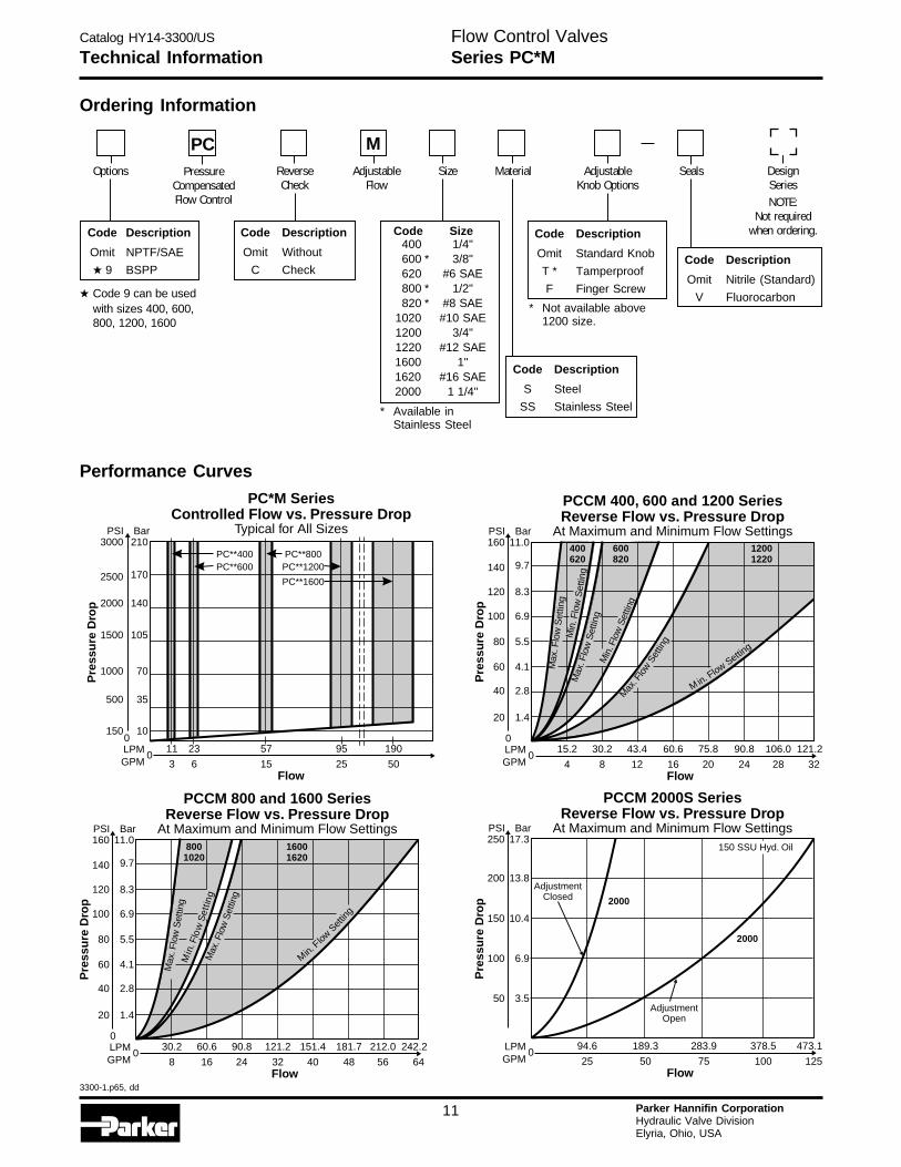
Technical Information
PC*M SeriesControlled Flow vs. Pressure Drop
Typical for All Sizes
095 19057
25 5015
2311
63Flow
Pre
ssu
re D
rop
LPMGPM
0150 10
500 35
1500
2000
1000
105
140
70
2500
3000PSI
170
210Bar
PC**400 PC**800PC**600 PC**1200
PC**1600
PCCM 400, 600 and 1200 SeriesReverse Flow vs. Pressure Drop
At Maximum and Minimum Flow Settings
075.8 90.8 106.043.4 60.6
20 24 2812 16
121.2
32
30.215.2
84Flow
Pre
ssu
re D
rop
LPMGPM
0
20 1.4
40 2.8
60 4.1
100
120
80
6.9
8.3
5.5
140
160PSI
9.7
11.0Bar
Max
. Flo
wS
ettin
g
Max
. Flo
wSe
tting
Max
. Flo
wS
ettin
g
Min
. Flo
wS
ettin
g
M in. Flow
Setting
Min
. Flo
Set
ting
w
600820
12001220
400620
PCCM 800 and 1600 SeriesReverse Flow vs. Pressure Drop
At Maximum and Minimum Flow Settings
0151.4 181.7 212.090.8 121.2
40 48 5624 32
242.2
64
60.630.2
168Flow
Pre
ssu
re D
rop
LPMGPM
0
20 1.4
40 2.8
60 4.1
100
120
80
6.9
8.3
5.5
140
160PSI
9.7
11.0Bar
Max
. Flo
wS
ettin
g
Max
. Flo
wS
ettin
g
Min
. Flo
wS
ettin
g
Min.Flow
Settin
g
8001020
16001620
Code Description
Omit Nitrile (Standard)
V Fluorocarbon
Ordering Information
Code Description
Omit Standard Knob
T * Tamperproof
F Finger Screw
AdjustableKnob Options
Seals DesignSeriesNOTE:
Not requiredwhen ordering.
Performance Curves
* Not available above1200 size.
Options
Code Description
Omit NPTF/SAE
★ 9 BSPP
Code Description
Omit Without
C Check
ReverseCheck
AdjustableFlow
MSize
Code Description
S Steel
SS Stainless Steel
Material
PCPressure
CompensatedFlow Control
* Available inStainless Steel
150 SSU Hyd. Oil
PCCM 2000S SeriesReverse Flow vs. Pressure Drop
At Maximum and Minimum Flow Settings
0189.3
50
94.6
25
Pre
ssu
re D
rop
LPMGPM
50 3.5
100 6.9
150
200
10.4
13.8
250PSI
17.3Bar
283.9 378.5
75 100
473.1
125Flow
2000
2000
AdjustmentClosed
AdjustmentOpen
Flow Control ValvesSeries PC*M
400 1/4"600 * 3/8"620 #6 SAE800 * 1/2"820 * #8 SAE
1020 #10 SAE1200 3/4"1220 #12 SAE1600 1"1620 #16 SAE2000 1 1/4"
Code Size
★ Code 9 can be usedwith sizes 400, 600,800, 1200, 1600
Catalog HY14-3300/US
3300-1.p65, dd
12 Parker Hannifin CorporationHydraulic Valve DivisionElyria, Ohio, USA
H
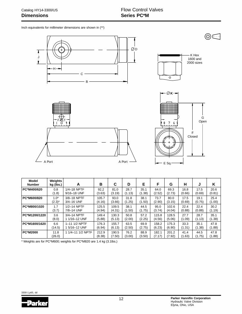
Dimensions
Inch equivalents for millimeter dimensions are shown in (**)
Model WeightsNumber kg (lbs.) A B C D E F G H J K
PC*M400/620 0.8 1/4–18 NPTF 92.2 81.0 28.7 35.1 64.0 69.3 16.8 17.5 20.6(1.8) 9/16–18 UNF (3.63) (3.19) (1.13) (1.38) (2.52) (2.73) (0.66) (0.69) (0.81)
PC*M600/820 1.0* 3/8–18 NPTF 105.7 93.0 31.8 38.1 73.7 80.0 17.5 19.1 25.4(2.3)* 3/4–16 UNF (4.16) (3.66) (1.25) (1.50) (2.90) (3.15) (0.69) (0.75) (1.00)
PC*M800/1020 1.7 1/2–14 NPTF 125.5 109.5 38.1 44.5 95.0 102.6 22.4 22.4 30.2(3.7) 7/8–14 UNF (4.94) (4.31) (1.50) (1.75) (3.74) (4.04) (0.88) (0.88) (1.19)
PC*M1200/1220 3.6 3/4–14 NPTF 149.4 130.3 50.8 57.2 115.8 128.5 27.7 28.7 35.1(8.0) 1 1/16–12 UNF (5.88) (5.13) (2.00) (2.25) (4.56) (5.06) (1.09) (1.13) (1.38)
PC*M1600/1620 6.6 1–11 1/2 NPTF 176.3 155.7 63.5 69.9 158.2 175.3 33.3 35.1 47.8(14.5) 1 5/16–12 UNF (6.94) (6.13) (2.50) (2.75) (6.23) (6.90) (1.31) (1.38) (1.88)
PC*M2000 11.8 1 1/4–11 1/2 NPTF 212.9 190.5 76.2 88.9 182.1 201.2 41.4 44.5 47.8(26.0) (8.38) (7.50) (3.00) (3.50) (7.17) (7.92) (1.63) (1.75) (1.88)
* Weights are for PC*M600; weights for PC*M820 are 1.4 kg (3.1lbs.)
Flow Control ValvesSeries PC*M
B
C
H
J
D
K Hex1600 and
2000 sizes
K
GOpen
FClosed
E Sq.A Port A Port
Catalog HY14-3300/US
3300-1.p65, dd
13 Parker Hannifin CorporationHydraulic Valve DivisionElyria, Ohio, USA
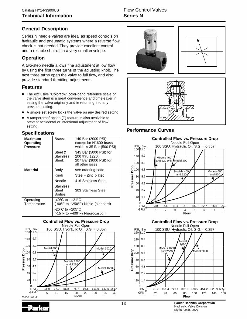
General DescriptionSeries N needle valves are ideal as speed controls onhydraulic and pneumatic systems where a reverse flowcheck is not needed. They provide excellent controland a reliable shut-off in a very small envelope.
OperationA two-step needle allows fine adjustment at low flowby using the first three turns of the adjusting knob. Thenext three turns open the valve to full flow, and alsoprovide standard throttling adjustments.
Features
• The exclusive “Colorflow” color-band reference scale onthe valve stem is a great convenience and time-saver insetting the valve originally and in returning it to anyprevious setting.
• A simple set screw locks the valve on any desired setting.
• A tamperproof option (T) feature is also available toprevent accidental or intentional adjustment of flowsetting.
Specifications
Technical Information
Controlled Flow vs. Pressure DropNeedle Full Open
100 SSU, Hydraulic Oil, S.G. = 0.857
075.7 94.6 113.656.8
20 25 3015
132.5 151.4
35 40
37.918.9
105Flow
Pre
ssu
re D
rop
LPMGPM
0
20 1.4
40 2.7
60 4.1
100
120
80
6.8
8.2
5.7
140
160PSI
9.7
11.0Bar
Model 1600
Model 1020Model 800
Models 1200and 1220
Maximum Brass: 140 Bar (2000 PSI);Operating except for N1600 brassPressure which is 35 Bar (500 PSI)
Steel & 345 Bar (5000 PSI) forStainless 200 thru 1220;Steel: 207 Bar (3000 PSI) for
all other sizes
Material Body see ordering code
Knob Steel - Zinc plated
Needle 416 Stainless Steel
StainlessSteel 303 Stainless SteelBodies
Operating -40°C to +121°CTemperature (-40°F to +250°F) Nitrile (standard)
-26°C to +205°C(-15°F to +400°F) Fluorocarbon
Performance Curves
Controlled Flow vs. Pressure DropNeedle Full Open
100 SSU, Hydraulic Oil, S.G. = 0.857
015.1 18.9 22.711.4
4 5 63
26.5 30.3
7 8
7.63.8
21Flow
Pre
ssu
re D
rop
LPMGPM
0
20 1.4
40 2.7
60 4.1
100
120
80
6.8
8.2
5.7
140
160PSI
9.7
11.0Bar
Models 400and 620 (#4)
Models 600and 820
Models 400and 620
Model 200
Controlled Flow vs. Pressure DropNeedle Full Open
100 SSU, Hydraulic Oil, S.G. = 0.857
0302.8 378.5 454.2227.1
80 100 12060
529.9 605.6
140 160
151.475.7
4020Flow
Pre
ssu
re D
rop
LPMGPM
0
20 1.4
40 2.7
60 4.1
100
120
80
6.8
8.2
5.7
140
160PSI
9.7
11.0Bar
Model 2020
Model1620
Models 1600and 2000
Flow Control ValvesSeries N
Catalog HY14-3300/US
3300-1.p65, dd
14 Parker Hannifin CorporationHydraulic Valve DivisionElyria, Ohio, USA
H
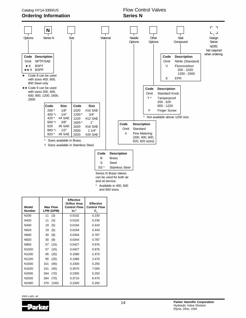
Ordering Information
Code DescriptionB Brass
S Steel
SS * Stainless Steel
DesignSeriesNOTE:
Not requiredwhen ordering.
Options Series N Size Material NeedleOptions
OtherOptions
NSeal
Compound
Code DescriptionOmit Nitrile (Standard)
V Fluorocarbon200 - 10201200 - 2000
E EPR
* Not available above 1200 size.
Code DescriptionOmit Standard Knob
T * Tamperproof200 - 620800 - 1220
F Finger Screw
Code DescriptionOmit Standard
4 Fine Metering(200, 400, 600,620, 820 sizes)
Code DescriptionOmit NPTF/SAE
★ 8 BSPT★★ 9 BSPP
Series N Brass Valvescan be used for both airand oil service.
* Available in 400, 600and 800 sizes.
* Sizes available in Brass.
† Sizes available in Stainless Steel.
Flow Control ValvesSeries N
EffectiveOrifice Area Effective
Model Max Flow Control Flow Control FlowNumber LPM (GPM) in.2 Cv
N200 11 (3) 0.0102 0.230
N420 11 (3) 0.0102 0.230
N400 19 (5) 0.0194 0.443
N620 19 (5) 0.0194 0.443
N600 30 (8) 0.0344 0.787
N820 30 (8) 0.0344 0.787
N800 57 (15) 0.0427 0.976
N1020 57 (15) 0.0427 0.976
N1200 95 (25) 0.1080 2.470
N1220 95 (25) 0.1080 2.470
N1600 151 (40) 0.2300 5.250
N1620 151 (40) 0.3070 7.000
N2000 264 (70) 0.2300 5.250
N2020 264 (70) 0.3710 8.470
N2400 379 (100) 0.2300 5.250
200 * 1/8"400 *† 1/4"420 * #4 SAE600 *† 3/8"620 #6 SAE800 *† 1/2"820 * #8 SAE
1020 #10 SAE1200 * 3/4"1220 #12 SAE1600 * 1"1620 #16 SAE2000 1 1/4"2020 #20 SAE
Code Size Code Size
★ Code 8 can be usedwith sizes 400, 600,800 Steel only
★★ Code 9 can be usedwith sizes 200, 400,600, 800, 1200, 1600,2000
Catalog HY14-3300/US
3300-1.p65, dd
15 Parker Hannifin CorporationHydraulic Valve DivisionElyria, Ohio, USA
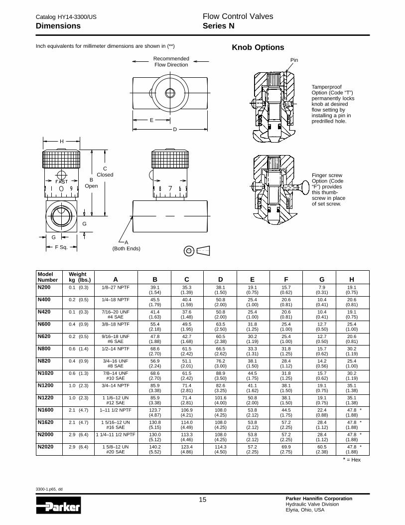
Dimensions
Model WeightNumber kg (lbs.) A B C D E F G HN200 0.1 (0.3) 1/8–27 NPTF 39.1 35.3 38.1 19.1 15.7 7.9 19.1
(1.54) (1.39) (1.50) (0.75) (0.62) (0.31) (0.75)
N400 0.2 (0.5) 1/4–18 NPTF 45.5 40.4 50.8 25.4 20.6 10.4 20.6(1.79) (1.59) (2.00) (1.00) (0.81) (0.41) (0.81)
N420 0.1 (0.3) 7/16–20 UNF 41.4 37.6 50.8 25.4 20.6 10.4 19.1#4 SAE (1.63) (1.48) (2.00) (1.00) (0.81) (0.41) (0.75)
N600 0.4 (0.9) 3/8–18 NPTF 55.4 49.5 63.5 31.8 25.4 12.7 25.4(2.18) (1.95) (2.50) (1.25) (1.00) (0.50) (1.00)
N620 0.2 (0.5) 9/16–18 UNF 47.8 42.7 60.5 30.2 25.4 12.7 20.6#6 SAE (1.88) (1.68) (2.38) (1.19) (1.00) (0.50) (0.81)
N800 0.6 (1.4) 1/2–14 NPTF 68.6 61.5 66.5 33.3 31.8 15.7 30.2(2.70) (2.42) (2.62) (1.31) (1.25) (0.62) (1.19)
N820 0.4 (0.9) 3/4–16 UNF 56.9 51.1 76.2 38.1 28.4 14.2 25.4#8 SAE (2.24) (2.01) (3.00) (1.50) (1.12) (0.56) (1.00)
N1020 0.6 (1.3) 7/8–14 UNF 68.6 61.5 88.9 44.5 31.8 15.7 30.2#10 SAE (2.70) (2.42) (3.50) (1.75) (1.25) (0.62) (1.19)
N1200 1.0 (2.3) 3/4–14 NPTF 85.9 71.4 82.6 41.1 38.1 19.1 35.1(3.38) (2.81) (3.25) (1.62) (1.50) (0.75) (1.38)
N1220 1.0 (2.3) 1 1/6–12 UN 85.9 71.4 101.6 50.8 38.1 19.1 35.1#12 SAE (3.38) (2.81) (4.00) (2.00) (1.50) (0.75) (1.38)
N1600 2.1 (4.7) 1–11 1/2 NPTF 123.7 106.9 108.0 53.8 44.5 22.4 47.8 *(4.87) (4.21) (4.25) (2.12) (1.75) (0.88) (1.88)
N1620 2.1 (4.7) 1 5/16–12 UN 130.8 114.0 108.0 53.8 57.2 28.4 47.8 *#16 SAE (5.15) (4.49) (4.25) (2.12) (2.25) (1.12) (1.88)
N2000 2.9 (6.4) 1 1/4–11 1/2 NPTF 130.0 113.3 108.0 53.8 57.2 28.4 47.8 *(5.12) (4.46) (4.25) (2.12) (2.25) (1.12) (1.88)
N2020 2.9 (6.4) 1 5/8–12 UN 140.2 123.4 114.3 57.2 69.9 60.5 47.8 *#20 SAE (5.52) (4.86) (4.50) (2.25) (2.75) (2.38) (1.88)
* = Hex
Inch equivalents for millimeter dimensions are shown in (**)
RecommendedFlow Direction
E
D
A(Both Ends)
H
CClosed
BOpen
G
G
F Sq.
Flow Control ValvesSeries N
Knob Options
Pin
TamperproofOption (Code “T”)permanently locksknob at desiredflow setting byinstalling a pin inpredrilled hole.
Finger screwOption (Code“F”) providesthis thumb-screw in placeof set screw.
Catalog HY14-3300/US
3300-1.p65, dd
16 Parker Hannifin CorporationHydraulic Valve DivisionElyria, Ohio, USA
H
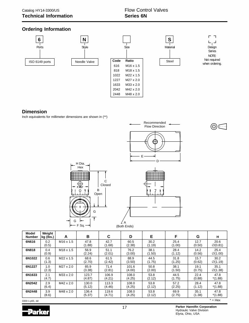
Technical InformationFlow Control ValvesSeries 6N
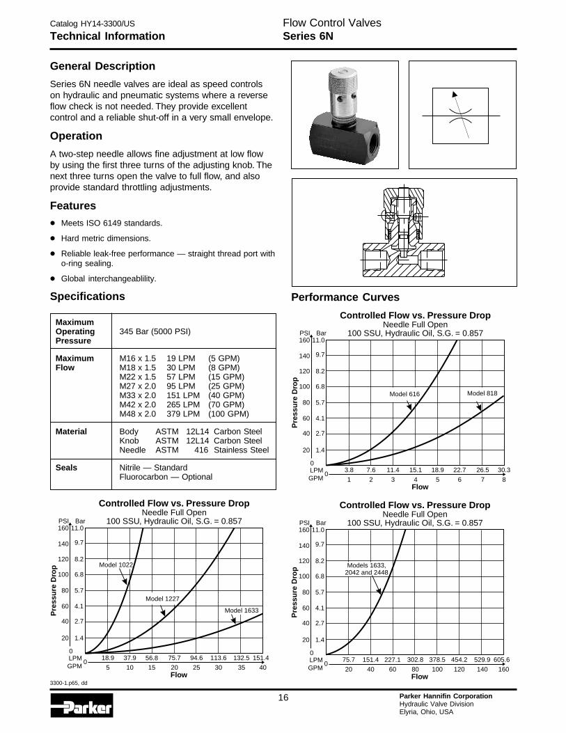
General Description
Series 6N needle valves are ideal as speed controlson hydraulic and pneumatic systems where a reverseflow check is not needed. They provide excellentcontrol and a reliable shut-off in a very small envelope.
Operation
A two-step needle allows fine adjustment at low flowby using the first three turns of the adjusting knob. Thenext three turns open the valve to full flow, and alsoprovide standard throttling adjustments.
Features
• Meets ISO 6149 standards.
• Hard metric dimensions.
• Reliable leak-free performance — straight thread port witho-ring sealing.
• Global interchangeablility.
Specifications
MaximumOperating 345 Bar (5000 PSI)Pressure
Maximum M16 x 1.5 19 LPM (5 GPM)Flow M18 x 1.5 30 LPM (8 GPM)
M22 x 1.5 57 LPM (15 GPM)M27 x 2.0 95 LPM (25 GPM)M33 x 2.0 151 LPM (40 GPM)M42 x 2.0 265 LPM (70 GPM)M48 x 2.0 379 LPM (100 GPM)
Material Body ASTM 12L14 Carbon SteelKnob ASTM 12L14 Carbon SteelNeedle ASTM 416 Stainless Steel
Seals Nitrile — StandardFluorocarbon — Optional
Controlled Flow vs. Pressure DropNeedle Full Open
100 SSU, Hydraulic Oil, S.G. = 0.857
075.7 94.6 113.656.8
20 25 3015
132.5 151.4
35 40
37.918.9
105Flow
Pre
ssu
re D
rop
LPMGPM
0
20 1.4
40 2.7
60 4.1
100
120
80
6.8
8.2
5.7
140
160PSI
9.7
11.0Bar
Model 1633
Model 1022
Model 1227
Performance Curves
Controlled Flow vs. Pressure DropNeedle Full Open
100 SSU, Hydraulic Oil, S.G. = 0.857
015.1 18.9 22.711.4
4 5 63
26.5 30.3
7 8
7.63.8
21Flow
Pre
ssu
re D
rop
LPMGPM
0
20 1.4
40 2.7
60 4.1
100
120
80
6.8
8.2
5.7
140
160PSI
9.7
11.0Bar
Model 818Model 616
Controlled Flow vs. Pressure DropNeedle Full Open
100 SSU, Hydraulic Oil, S.G. = 0.857
0302.8 378.5 454.2227.1
80 100 12060
529.9 605.6
140 160
151.475.7
4020Flow
Pre
ssu
re D
rop
LPMGPM
0
20 1.4
40 2.7
60 4.1
100
120
80
6.8
8.2
5.7
140
160PSI
9.7
11.0Bar
Models 1633,2042 and 2448
Catalog HY14-3300/US
3300-1.p65, dd
17 Parker Hannifin CorporationHydraulic Valve DivisionElyria, Ohio, USA
Technical InformationFlow Control ValvesSeries 6N
DimensionInch equivalents for millimeter dimensions are shown in (**)
SteelCode Ratio
616 M16 x 1.5
818 M18 x 1.5
1022 M22 x 1.5
1227 M27 x 2.0
1633 M33 x 2.0
2042 M42 x 2.0
2448 M48 x 2.0
Needle ValveISO 6149 ports
Ordering Information
DesignSeriesNOTE:
Not requiredwhen ordering.
Ports Style Size Material
N S6
E
D
A(Both Ends)
H Dia.Hex
CClosed
BOpen
G
GF Sq.
RecommendedFlow Direction
Model WeightNumber kg (lbs.) A B C D E F G H6N616 0.2 M16 x 1.5 47.8 42.7 60.5 30.2 25.4 12.7 20.6
(0.5) (1.88) (1.68) (2.38) (1.19) (1.00) (0.50) ∅(0.81)
6N818 0.4 M18 x 1.5 56.9 51.1 76.2 38.1 28.4 14.2 25.4(0.9) (2.24) (2.01) (3.00) (1.50) (1.12) (0.56) ∅(1.00)
6N1022 0.6 M22 x 1.5 68.6 61.5 88.9 44.5 31.8 15.7 30.2(1.3) (2.70) (2.42) (3.50) (1.75) (1.25) (0.62) ∅(1.19)
6N1227 1.0 M27 x 2.0 85.9 71.4 101.6 50.8 38.1 19.1 35.1(2.3) (3.38) (2.81) (4.00) (2.00) (1.50) (0.75) ∅(1.38)
6N1633 2.1 M33 x 2.0 123.7 106.9 108.0 53.8 44.5 22.4 47.8(4.7) (4.87) (4.21) (4.25) (2.12) (1.75) (0.88) *(1.88)
6N2042 2.9 M42 x 2.0 130.0 113.3 108.0 53.8 57.2 28.4 47.8(6.4) (5.12) (4.46) (4.25) (2.12) (2.25) (1.12) *(1.88)
6N2448 3.9 M48 x 2.0 136.4 119.6 108.0 53.8 69.9 35.1 47.8(8.6) (5.37) (4.71) (4.25) (2.12) (2.75) (1.38) *(1.88)
* = Hex
Catalog HY14-3300/US
3300-1.p65, dd
18 Parker Hannifin CorporationHydraulic Valve DivisionElyria, Ohio, USA
H
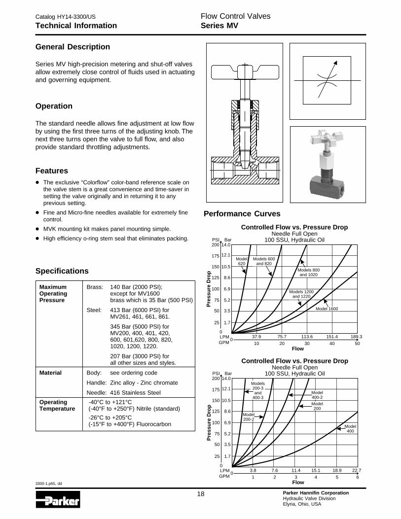
General Description
Series MV high-precision metering and shut-off valvesallow extremely close control of fluids used in actuatingand governing equipment.
Operation
The standard needle allows fine adjustment at low flowby using the first three turns of the adjusting knob. Thenext three turns open the valve to full flow, and alsoprovide standard throttling adjustments.
Technical Information
Maximum Brass: 140 Bar (2000 PSI);Operating except for MV1600Pressure brass which is 35 Bar (500 PSI)
Steel: 413 Bar (6000 PSI) forMV261, 461, 661, 861.
345 Bar (5000 PSI) forMV200, 400, 401, 420,600, 601,620, 800, 820,1020, 1200, 1220.
207 Bar (3000 PSI) forall other sizes and styles.
Material Body: see ordering code
Handle: Zinc alloy - Zinc chromate
Needle: 416 Stainless Steel
Operating -40°C to +121°CTemperature (-40°F to +250°F) Nitrile (standard)
-26°C to +205°C(-15°F to +400°F) Fluorocarbon
Features
• The exclusive “Colorflow” color-band reference scale onthe valve stem is a great convenience and time-saver insetting the valve originally and in returning it to anyprevious setting.
• Fine and Micro-fine needles available for extremely finecontrol.
• MVK mounting kit makes panel mounting simple.
• High efficiency o-ring stem seal that eliminates packing.
Performance Curves
Controlled Flow vs. Pressure DropNeedle Full Open
100 SSU, Hydraulic Oil
0113.6 151.475.7
30 4020
189.3
50
37.9
10Flow
Pre
ssu
re D
rop
LPMGPM
0
25 1.7
50 3.5
75 5.2
125
150
100
8.6
10.5
6.9
175
200PSI
12.1
14.0Bar
Model620
Models 1200and 1220
Models 800and 1020
Models 600and 820
Model 1600
Controlled Flow vs. Pressure DropNeedle Full Open
100 SSU, Hydraulic Oil
011.4 15.1 18.97.6
3 4 52
22.7
6
3.8
1Flow
Pre
ssu
re D
rop
LPMGPM
0
25 1.7
50 3.5
75 5.2
125
150
100
8.6
10.5
6.9
175
200PSI
12.1
14.0Bar
Models200-3and
400-3Model400-2
Model200
Model400
Model200-2
Flow Control ValvesSeries MV
Specifications
Catalog HY14-3300/US
3300-1.p65, dd
19 Parker Hannifin CorporationHydraulic Valve DivisionElyria, Ohio, USA
Technical Information
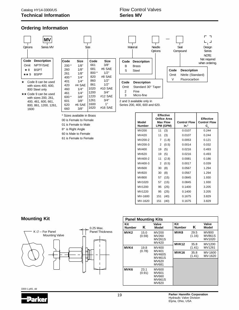
Ordering Information
Mounting Kit
Code DescriptionB Brass
S Steel
DesignSeriesNOTE:
Not requiredwhen ordering.
Options Series MV Size Material NeedleOptions
MVSeal
Compound
Code DescriptionOmit Nitrile (Standard)
V FluorocarbonCode DescriptionOmit Standard 30° Taper
2 Fine3 Micro-fine
Code DescriptionOmit NPTF/SAE
★ 8 BSPT
★★ 9 BSPP
2 and 3 available only inSeries 200, 400, 600 and 620.
* Sizes available in Brass
00 is Female to Female
01 is Female to Male
6* is Right Angle
60 is Male to Female
61 is Female to Female
Flow Control ValvesSeries MV
200 * 1/8"260 1/8"261 1/8"400 * 1/4"401 1/4"420 #4 SAE460 1/4"461 1/4"600 * 3/8"601 3/8"620 #6 SAE660 3/8"
Code Size Code Size661 3/8"681 #6 SAE800 * 1/2"820 #8 SAE860 1/2"861 1/2"
1020 #10 SAE1200 3/4"1220 #12 SAE1261 3/4"1600 1"1620 #16 SAE
EffectiveOrifice Area Effective
Model Max Flow Control Flow Control FlowNumber LPM (GPM) in.2 Cv
MV200 11 (3) 0.0107 0.244
MV420 11 (3) 0.0107 0.244
MV200-2 7 (1.8) 0.0053 0.121
MV200-3 2 (0.5) 0.0014 0.032
MV400 19 (5) 0.0216 0.493
MV620 19 (5) 0.0216 0.493
MV400-2 11 (2.8) 0.0081 0.186
MV400-3 2 (0.5) 0.0017 0.039
MV600 30 (8) 0.0567 1.294
MV820 30 (8) 0.0567 1.294
MV800 57 (15) 0.0845 1.930
MV1020 57 (15) 0.0845 1.930
MV1200 95 (25) 0.1400 3.205
MV1220 95 (25) 0.1400 3.205
MV-1600 151 (40) 0.1675 3.829
MV-1620 151 (40) 0.1675 3.829
K – For PanelMounting Valve
�
0.25 Max.Panel Thickness
Panel Mounting KitsKit ValveNumber K Model
MVK2 15.0 MV200(0.59) MV260
MV261SMV420
MVK4 19.8 MV400(0.78) MV401
MV460SMV461SMV620MV681
MVK6 23.1 MV600(0.91) MV601
MV660MV661SMV820
Kit ValveNumber K Model
MVK8 29.5 MV800(1.16) MV861S
MV1020
MVK12 35.8 MV1200(1.41) MV1261
MVK16 35.8 MV-1600(1.41) MV-1620
★ Code 8 can be usedwith sizes 400, 600,800 Steel only
★★ Code 9 can be usedwith sizes 200, 261,400, 461, 600, 661,800, 861, 1200, 1261,1600
Catalog HY14-3300/US
3300-1.p65, dd
20 Parker Hannifin CorporationHydraulic Valve DivisionElyria, Ohio, USA
H
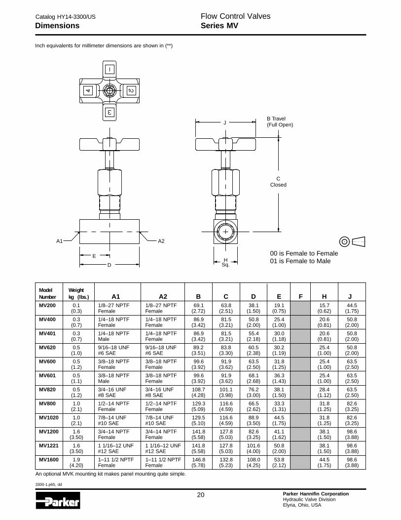
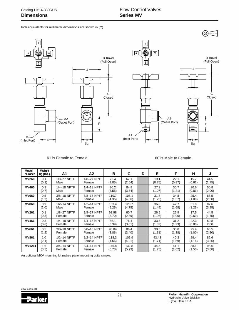
Inch equivalents for millimeter dimensions are shown in (**)
Dimensions
B Travel(Full Open)
CClosed
J
A2A1
HSq.
E
D
00 is Female to Female01 is Female to Male
Flow Control ValvesSeries MV
An optional MVK mounting kit makes panel mounting quite simple.
Model WeightNumber kg (lbs.) A1 A2 B C D E F H JMV200 0.1 1/8–27 NPTF 1/8–27 NPTF 69.1 63.8 38.1 19.1 15.7 44.5
(0.3) Female Female (2.72) (2.51) (1.50) (0.75) (0.62) (1.75)
MV400 0.3 1/4–18 NPTF 1/4–18 NPTF 86.9 81.5 50.8 25.4 20.6 50.8(0.7) Female Female (3.42) (3.21) (2.00) (1.00) (0.81) (2.00)
MV401 0.3 1/4–18 NPTF 1/4–18 NPTF 86.9 81.5 55.4 30.0 20.6 50.8(0.7) Male Female (3.42) (3.21) (2.18) (1.18) (0.81) (2.00)
MV620 0.5 9/16–18 UNF 9/16–18 UNF 89.2 83.8 60.5 30.2 25.4 50.8(1.0) #6 SAE #6 SAE (3.51) (3.30) (2.38) (1.19) (1.00) (2.00)
MV600 0.5 3/8–18 NPTF 3/8–18 NPTF 99.6 91.9 63.5 31.8 25.4 63.5(1.2) Female Female (3.92) (3.62) (2.50) (1.25) (1.00) (2.50)
MV601 0.5 3/8–18 NPTF 3/8–18 NPTF 99.6 91.9 68.1 36.3 25.4 63.5(1.1) Male Female (3.92) (3.62) (2.68) (1.43) (1.00) (2.50)
MV820 0.5 3/4–16 UNF 3/4–16 UNF 108.7 101.1 76.2 38.1 28.4 63.5(1.2) #8 SAE #8 SAE (4.28) (3.98) (3.00) (1.50) (1.12) (2.50)
MV800 1.0 1/2–14 NPTF 1/2–14 NPTF 129.3 116.6 66.5 33.3 31.8 82.6(2.1) Female Female (5.09) (4.59) (2.62) (1.31) (1.25) (3.25)
MV1020 1.0 7/8–14 UNF 7/8–14 UNF 129.5 116.6 88.9 44.5 31.8 82.6(2.1) #10 SAE #10 SAE (5.10) (4.59) (3.50) (1.75) (1.25) (3.25)
MV1200 1.6 3/4–14 NPTF 3/4–14 NPTF 141.8 127.8 82.6 41.1 38.1 98.6(3.50) Female Female (5.58) (5.03) (3.25) (1.62) (1.50) (3.88)
MV1221 1.6 1 1/16–12 UNF 1 1/16–12 UNF 141.8 127.8 101.6 50.8 38.1 98.6(3.50) #12 SAE #12 SAE (5.58) (5.03) (4.00) (2.00) (1.50) (3.88)
MV1600 1.9 1–11 1/2 NPTF 1–11 1/2 NPTF 146.8 132.8 108.0 53.8 44.5 98.6(4.20) Female Female (5.78) (5.23) (4.25) (2.12) (1.75) (3.88)
Catalog HY14-3300/US
3300-1.p65, dd
21 Parker Hannifin CorporationHydraulic Valve DivisionElyria, Ohio, USA
Inch equivalents for millimeter dimensions are shown in (**)
Dimensions
Model WeightNumber kg (lbs.) A1 A2 B C D E F H JMV260 0.1 1/8–27 NPTF 1/8–27 NPTF 72.4 67.1 19.1 22.1 15.7 44.5
(0.3) Male Female (2.85) (2.64) (0.75) (0.87) (0.62) (1.75)
MV460 0.3 1/4–18 NPTF 1/4–18 NPTF 90.2 84.8 27.2 30.7 20.6 50.8(0.7) Male Female (3.55) (3.34) (1.07) (1.21) (0.81) (2.00)
MV660 0.5 3/8–18 NPTF 3/8–18 NPTF 110.7 103.1 31.8 34.8 25.4 63.5(1.2) Male Female (4.36) (4.06) (1.25) (1.37) (1.00) (2.50)
MV860 0.9 1/2–14 NPTF 1/2–14 NPTF 133.4 120.7 36.8 42.7 31.8 82.6(2.0) Male Female (5.25) (4.75) (1.45) (1.68) (1.25) (3.25)
MV261 0.1 1/8–27 NPTF 1/8–27 NPTF 93.98 60.7 26.9 26.9 17.5 44.5(0.3) Female Female (3.70) (2.39) (1.06) (1.06) (0.69) (1.75)
MV461 0.3 1/4–18 NPTF 1/4–18 NPTF 86.1 76.4 33.5 31.2 22.3 50.8(0.6) Female Female (3.39) (3.01) (1.32) (1.23) (0.88) 2.00
MV661 0.5 3/8–18 NPTF 3/8–18 NPTF 98.04 86.4 38.3 35.0 25.4 63.5(1.2) Female Female (3.86) (3.40) (1.51) (1.38) (1.00) (2.50)
MV861 1.0 1/2–14 NPTF 1/2–14 NPTF 118.3 106.9 43.43 40.3 29.4 82.6(2.1) Female Female (4.66) (4.21) (1.71) (1.59) (1.16) (3.25)
MV1261 1.6 3/4–14 NPTF 3/4–14 NPTF 146.8 132.8 44.5 41.1 38.1 98.6(3.5) Female Female (5.78) (5.23) (1.75) (1.62) (1.50) (3.88)
Flow Control ValvesSeries MV
An optional MKV mounting kit makes panel mounting quite simple.
60 is Male to Female61 is Female to Female
CClosed
CClosed
B Travel(Full Open)
B Travel(Full Open)
A2(Outlet Port)
A2(Outlet Port)F F
HSq.
HSq.
E
JJ
EA1
(Inlet Port)
A1(Inlet Port)
Catalog HY14-3300/US
3300-1.p65, dd
22 Parker Hannifin CorporationHydraulic Valve DivisionElyria, Ohio, USA
H
Technical InformationFlow Control ValvesSeries 6MV
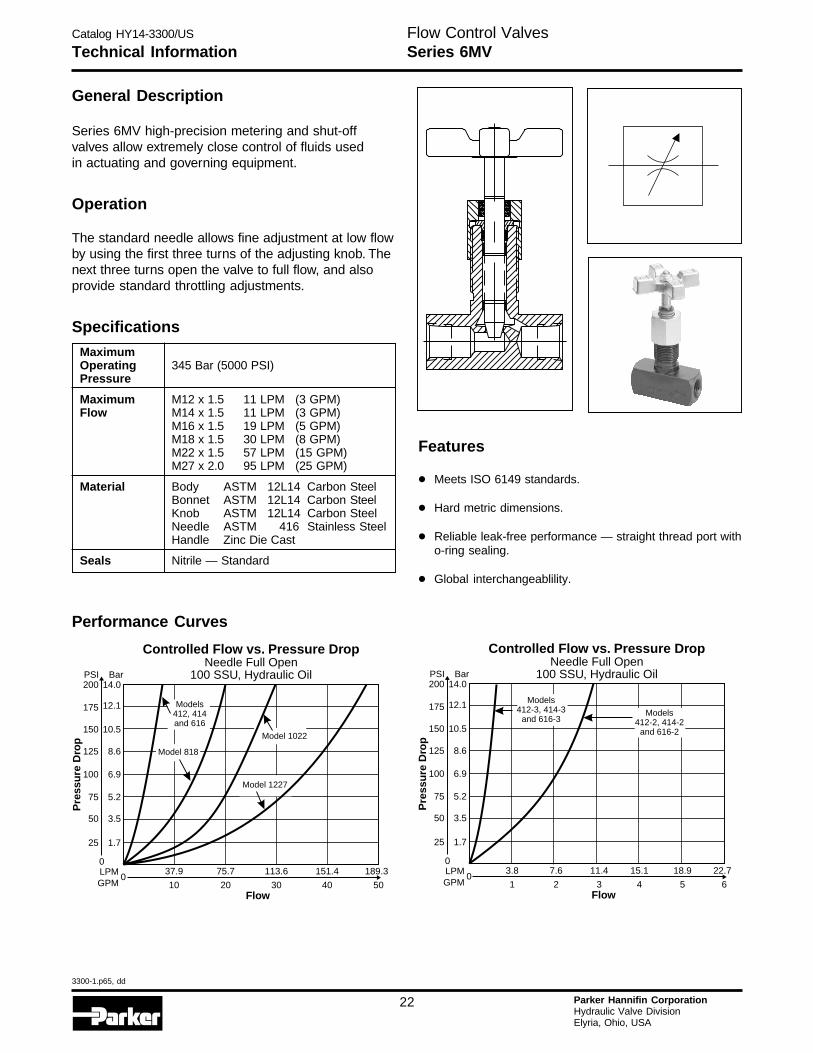
General Description
Series 6MV high-precision metering and shut-offvalves allow extremely close control of fluids usedin actuating and governing equipment.
Operation
The standard needle allows fine adjustment at low flowby using the first three turns of the adjusting knob. Thenext three turns open the valve to full flow, and alsoprovide standard throttling adjustments.
Specifications
MaximumOperating 345 Bar (5000 PSI)Pressure
Maximum M12 x 1.5 11 LPM (3 GPM)Flow M14 x 1.5 11 LPM (3 GPM)
M16 x 1.5 19 LPM (5 GPM)M18 x 1.5 30 LPM (8 GPM)M22 x 1.5 57 LPM (15 GPM)M27 x 2.0 95 LPM (25 GPM)
Material Body ASTM 12L14 Carbon SteelBonnet ASTM 12L14 Carbon SteelKnob ASTM 12L14 Carbon SteelNeedle ASTM 416 Stainless SteelHandle Zinc Die Cast
Seals Nitrile — Standard
Features
• Meets ISO 6149 standards.
• Hard metric dimensions.
• Reliable leak-free performance — straight thread port witho-ring sealing.
• Global interchangeablility.
Performance Curves
Controlled Flow vs. Pressure DropNeedle Full Open
100 SSU, Hydraulic Oil
0113.6 151.475.7
30 4020
189.3
50
37.9
10Flow
Pre
ssu
re D
rop
LPMGPM
0
25 1.7
50 3.5
75 5.2
125
150
100
8.6
10.5
6.9
175
200PSI
12.1
14.0Bar
Models412, 414and 616
Model 1227
Model 1022
Model 818
Controlled Flow vs. Pressure DropNeedle Full Open
100 SSU, Hydraulic Oil
011.4 15.1 18.97.6
3 4 52
22.7
6
3.8
1Flow
Pre
ssu
re D
rop
LPMGPM
0
25 1.7
50 3.5
75 5.2
125
150
100
8.6
10.5
6.9
175
200PSI
12.1
14.0Bar
Models412-3, 414-3
and 616-3Models
412-2, 414-2and 616-2
Catalog HY14-3300/US
3300-1.p65, dd
23 Parker Hannifin CorporationHydraulic Valve DivisionElyria, Ohio, USA
Technical InformationFlow Control ValvesSeries 6MV
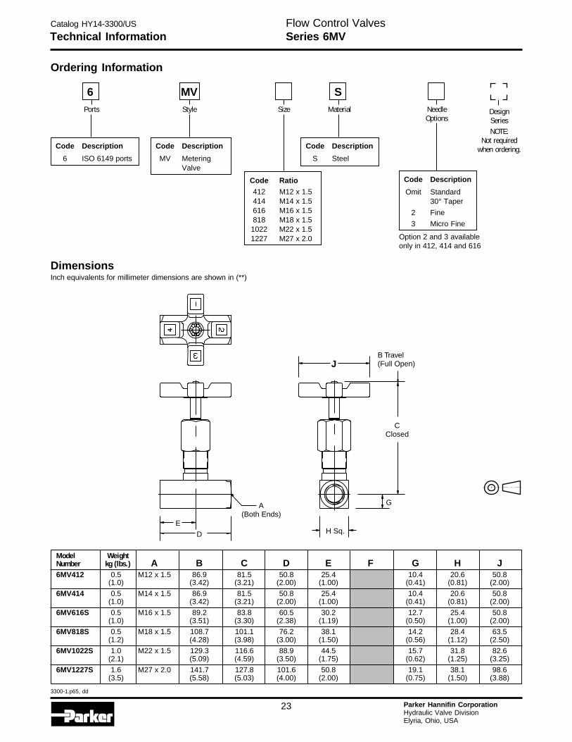
Ordering Information
DimensionsInch equivalents for millimeter dimensions are shown in (**)
Code Description
S Steel
Code Description
MV MeteringValve
Code Description
6 ISO 6149 ports
Code Ratio
412 M12 x 1.5414 M14 x 1.5616 M16 x 1.5818 M18 x 1.51022 M22 x 1.51227 M27 x 2.0
DesignSeriesNOTE:
Not requiredwhen ordering.
Ports Size Material
S6Style
MVNeedleOptions
Code Description
Omit Standard30° Taper
2 Fine
3 Micro Fine
Option 2 and 3 availableonly in 412, 414 and 616
Model WeightNumber kg (lbs.) A B C D E F G H J6MV412 0.5 M12 x 1.5 86.9 81.5 50.8 25.4 10.4 20.6 50.8
(1.0) (3.42) (3.21) (2.00) (1.00) (0.41) (0.81) (2.00)
6MV414 0.5 M14 x 1.5 86.9 81.5 50.8 25.4 10.4 20.6 50.8(1.0) (3.42) (3.21) (2.00) (1.00) (0.41) (0.81) (2.00)
6MV616S 0.5 M16 x 1.5 89.2 83.8 60.5 30.2 12.7 25.4 50.8(1.0) (3.51) (3.30) (2.38) (1.19) (0.50) (1.00) (2.00)
6MV818S 0.5 M18 x 1.5 108.7 101.1 76.2 38.1 14.2 28.4 63.5(1.2) (4.28) (3.98) (3.00) (1.50) (0.56) (1.12) (2.50)
6MV1022S 1.0 M22 x 1.5 129.3 116.6 88.9 44.5 15.7 31.8 82.6(2.1) (5.09) (4.59) (3.50) (1.75) (0.62) (1.25) (3.25)
6MV1227S 1.6 M27 x 2.0 141.7 127.8 101.6 50.8 19.1 38.1 98.6(3.5) (5.58) (5.03) (4.00) (2.00) (0.75) (1.50) (3.88)
B Travel(Full Open)
CClosed
J
A(Both Ends)
G
H Sq.D
E
Catalog HY14-3300/US
3300-1.p65, dd
24 Parker Hannifin CorporationHydraulic Valve DivisionElyria, Ohio, USA
H
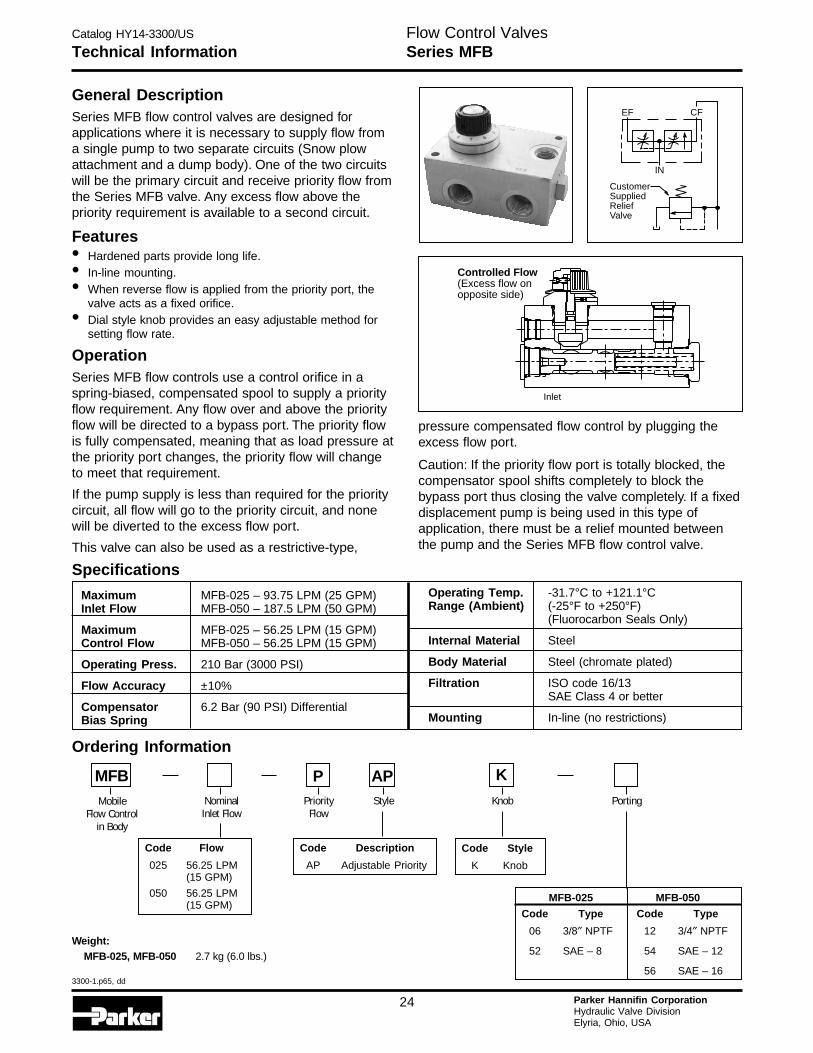
General DescriptionSeries MFB flow control valves are designed forapplications where it is necessary to supply flow froma single pump to two separate circuits (Snow plowattachment and a dump body). One of the two circuitswill be the primary circuit and receive priority flow fromthe Series MFB valve. Any excess flow above thepriority requirement is available to a second circuit.
Features• Hardened parts provide long life.• In-line mounting.• When reverse flow is applied from the priority port, the
valve acts as a fixed orifice.• Dial style knob provides an easy adjustable method for
setting flow rate.
OperationSeries MFB flow controls use a control orifice in aspring-biased, compensated spool to supply a priorityflow requirement. Any flow over and above the priorityflow will be directed to a bypass port. The priority flowis fully compensated, meaning that as load pressure atthe priority port changes, the priority flow will changeto meet that requirement.
If the pump supply is less than required for the prioritycircuit, all flow will go to the priority circuit, and nonewill be diverted to the excess flow port.
This valve can also be used as a restrictive-type,
Inlet
Controlled Flow(Excess flow onopposite side)
EF CF
IN
CustomerSuppliedReliefValve
Maximum MFB-025 – 93.75 LPM (25 GPM)Inlet Flow MFB-050 – 187.5 LPM (50 GPM)
Maximum MFB-025 – 56.25 LPM (15 GPM)Control Flow MFB-050 – 56.25 LPM (15 GPM)
Operating Press. 210 Bar (3000 PSI)
Flow Accuracy ±10%
Compensator 6.2 Bar (90 PSI) DifferentialBias Spring
Operating Temp. -31.7°C to +121.1°CRange (Ambient) (-25°F to +250°F)
(Fluorocarbon Seals Only)
Internal Material Steel
Body Material Steel (chromate plated)
Filtration ISO code 16/13SAE Class 4 or better
Mounting In-line (no restrictions)
Specifications
Technical Information
pressure compensated flow control by plugging theexcess flow port.
Caution: If the priority flow port is totally blocked, thecompensator spool shifts completely to block thebypass port thus closing the valve completely. If a fixeddisplacement pump is being used in this type ofapplication, there must be a relief mounted betweenthe pump and the Series MFB flow control valve.
Weight:MFB-025, MFB-050 2.7 kg (6.0 lbs.)
Code Flow
025 56.25 LPM(15 GPM)
050 56.25 LPM(15 GPM)
Code Description
AP Adjustable Priority
Code Style
K Knob
Ordering Information
APStyle PortingMobile
Flow Controlin Body
MFBNominal
Inlet FlowPriority
Flow
PKnob
K
MFB-025
Code Type
06 3/8″ NPTF
52 SAE – 8
MFB-050
Code Type
12 3/4″ NPTF
54 SAE – 12
56 SAE – 16
Flow Control ValvesSeries MFB
Catalog HY14-3300/US
3300-1.p65, dd
25 Parker Hannifin CorporationHydraulic Valve DivisionElyria, Ohio, USA
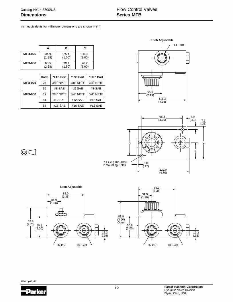
Dimensions
Inch equivalents for millimeter dimensions are shown in (**)
Code “EF” Port “IN” Port “CF” Port
MFB-025 06 3/8″ NPTF 3/8″ NPTF 3/8″ NPTF
52 #8 SAE #8 SAE #8 SAE
MFB-050 12 3/4″ NPTF 3/4″ NPTF 3/4″ NPTF
54 #12 SAE #12 SAE #12 SAE
56 #16 SAE #16 SAE #12 SAE
A B C
MFB-025 34.9 25.4 50.8(1.38) (1.00) (2.00)
MFB-050 60.5 38.1 76.2(2.38) (1.50) (3.00)
55.6(2.19)
111.3(4.38)
EF Port
Knob Adjustable
31.9(1.26)
17.3(.68)
85.9(3.38)
88.9(3.50)Open
50.8(2.00)
CF PortIN Port
85.9(3.38)
69.9(2.75) 50.8
(2.00)
31.9(1.26)
17.3(.68)
CF PortIN Port
Stem Adjustable
7.9(.31)
7.9(.31)
7.1 (.28) Dia. Thru2 Mounting Holes
95.3(3.75)
3.0(.12)
122.0(4.80)
A
B
C
Flow Control ValvesSeries MFB
Catalog HY14-3300/US
3300-1.p65, dd
26 Parker Hannifin CorporationHydraulic Valve DivisionElyria, Ohio, USA
H
Ordering Information
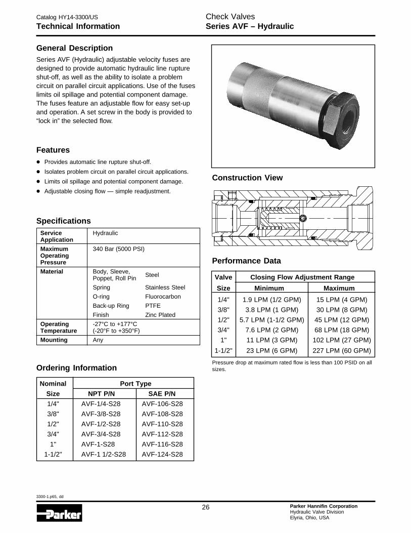
Technical InformationCheck ValvesSeries AVF – Hydraulic
General DescriptionSeries AVF (Hydraulic) adjustable velocity fuses aredesigned to provide automatic hydraulic line ruptureshut-off, as well as the ability to isolate a problemcircuit on parallel circuit applications. Use of the fuseslimits oil spillage and potential component damage.The fuses feature an adjustable flow for easy set-upand operation. A set screw in the body is provided to“lock in” the selected flow.
Features
• Provides automatic line rupture shut-off.
• Isolates problem circuit on parallel circuit applications.
• Limits oil spillage and potential component damage.
• Adjustable closing flow — simple readjustment.
Specifications
Valve Closing Flow Adjustment Range
Size Minimum Maximum
1/4" 1.9 LPM (1/2 GPM) 15 LPM (4 GPM)
3/8" 3.8 LPM (1 GPM) 30 LPM (8 GPM)
1/2" 5.7 LPM (1-1/2 GPM) 45 LPM (12 GPM)
3/4" 7.6 LPM (2 GPM) 68 LPM (18 GPM)
1" 11 LPM (3 GPM) 102 LPM (27 GPM)
1-1/2" 23 LPM (6 GPM) 227 LPM (60 GPM)
Pressure drop at maximum rated flow is less than 100 PSID on allsizes.
Performance Data
Service HydraulicApplication
Maximum 340 Bar (5000 PSI)OperatingPressure
Material Body, Sleeve, SteelPoppet, Roll Pin
Spring Stainless Steel
O-ring Fluorocarbon
Back-up Ring PTFE
Finish Zinc Plated
Operating -27°C to +177°CTemperature (-20°F to +350°F)
Mounting Any
Nominal Port Type
Size NPT P/N SAE P/N
1/4" AVF-1/4-S28 AVF-106-S28
3/8" AVF-3/8-S28 AVF-108-S28
1/2" AVF-1/2-S28 AVF-110-S28
3/4" AVF-3/4-S28 AVF-112-S28
1" AVF-1-S28 AVF-116-S28
1-1/2" AVF-1 1/2-S28 AVF-124-S28
Construction View
Catalog HY14-3300/US
3300-1.p65, dd
27 Parker Hannifin CorporationHydraulic Valve DivisionElyria, Ohio, USA
Technical InformationCheck ValvesSeries AVF – Hydraulic
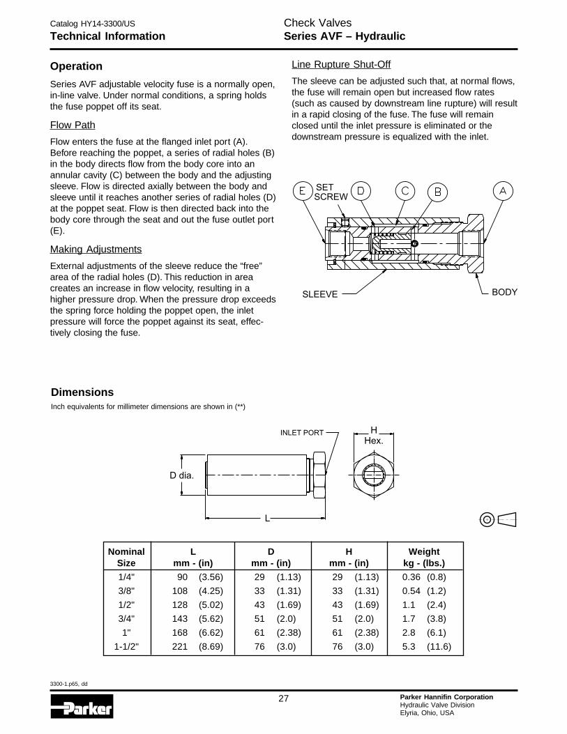
Operation
Series AVF adjustable velocity fuse is a normally open,in-line valve. Under normal conditions, a spring holdsthe fuse poppet off its seat.
Flow Path
Flow enters the fuse at the flanged inlet port (A).Before reaching the poppet, a series of radial holes (B)in the body directs flow from the body core into anannular cavity (C) between the body and the adjustingsleeve. Flow is directed axially between the body andsleeve until it reaches another series of radial holes (D)at the poppet seat. Flow is then directed back into thebody core through the seat and out the fuse outlet port(E).
Making Adjustments
External adjustments of the sleeve reduce the “free”area of the radial holes (D). This reduction in areacreates an increase in flow velocity, resulting in ahigher pressure drop. When the pressure drop exceedsthe spring force holding the poppet open, the inletpressure will force the poppet against its seat, effec-tively closing the fuse.
Line Rupture Shut-Off
The sleeve can be adjusted such that, at normal flows,the fuse will remain open but increased flow rates(such as caused by downstream line rupture) will resultin a rapid closing of the fuse. The fuse will remainclosed until the inlet pressure is eliminated or thedownstream pressure is equalized with the inlet.
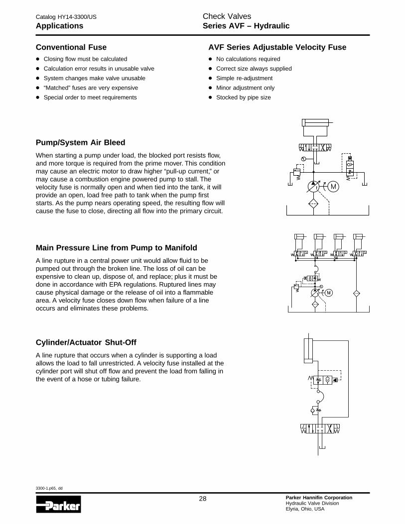
DimensionsInch equivalents for millimeter dimensions are shown in (**)
Nominal L D H WeightSize mm - (in) mm - (in) mm - (in) kg - (lbs.)
1/4" 90 (3.56) 29 (1.13) 29 (1.13) 0.36 (0.8)
3/8" 108 (4.25) 33 (1.31) 33 (1.31) 0.54 (1.2)
1/2" 128 (5.02) 43 (1.69) 43 (1.69) 1.1 (2.4)
3/4" 143 (5.62) 51 (2.0) 51 (2.0) 1.7 (3.8)
1" 168 (6.62) 61 (2.38) 61 (2.38) 2.8 (6.1)
1-1/2" 221 (8.69) 76 (3.0) 76 (3.0) 5.3 (11.6)
SLEEVE BODY
SET
SCREW
INLET PORT
D dia.
H
Hex.
L
Catalog HY14-3300/US
3300-1.p65, dd
28 Parker Hannifin CorporationHydraulic Valve DivisionElyria, Ohio, USA
H
Check ValvesSeries AVF – HydraulicApplications
Conventional Fuse
• Closing flow must be calculated
• Calculation error results in unusable valve
• System changes make valve unusable
• “Matched” fuses are very expensive
• Special order to meet requirements
AVF Series Adjustable Velocity Fuse
• No calculations required
• Correct size always supplied
• Simple re-adjustment
• Minor adjustment only
• Stocked by pipe size
Pump/System Air Bleed
When starting a pump under load, the blocked port resists flow,and more torque is required from the prime mover. This conditionmay cause an electric motor to draw higher “pull-up current,” ormay cause a combustion engine powered pump to stall. Thevelocity fuse is normally open and when tied into the tank, it willprovide an open, load free path to tank when the pump firststarts. As the pump nears operating speed, the resulting flow willcause the fuse to close, directing all flow into the primary circuit.
Main Pressure Line from Pump to Manifold
A line rupture in a central power unit would allow fluid to bepumped out through the broken line. The loss of oil can beexpensive to clean up, dispose of, and replace; plus it must bedone in accordance with EPA regulations. Ruptured lines maycause physical damage or the release of oil into a flammablearea. A velocity fuse closes down flow when failure of a lineoccurs and eliminates these problems.
Cylinder/Actuator Shut-Off
A line rupture that occurs when a cylinder is supporting a loadallows the load to fall unrestricted. A velocity fuse installed at thecylinder port will shut off flow and prevent the load from falling inthe event of a hose or tubing failure.
Catalog HY14-3300/US
3300-1.p65, dd
29 Parker Hannifin CorporationHydraulic Valve DivisionElyria, Ohio, USA
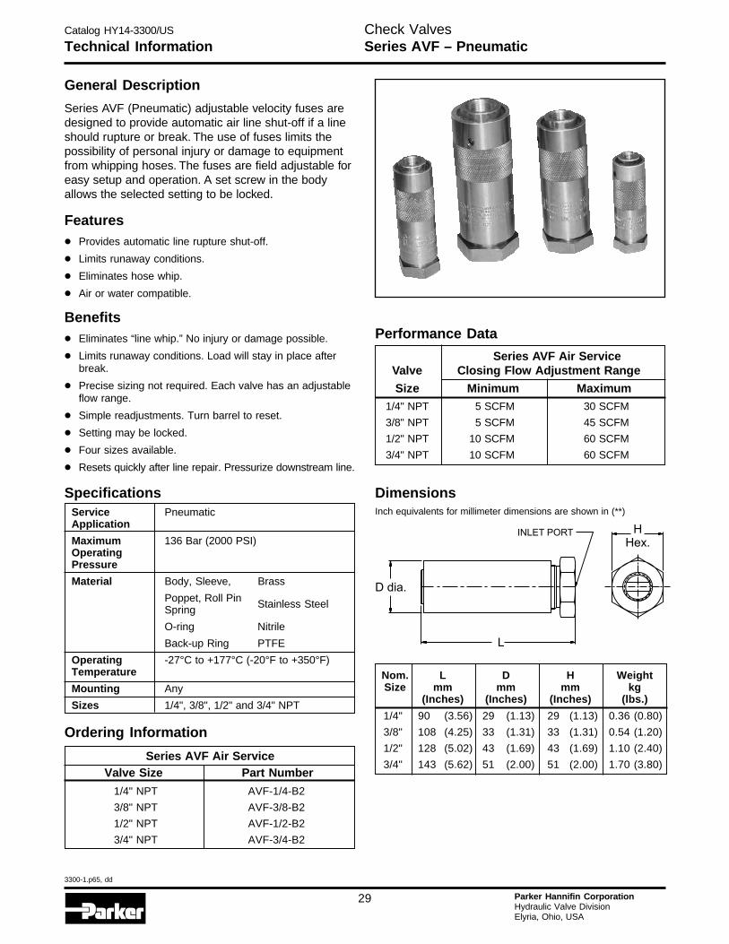
Technical InformationCheck ValvesSeries AVF – Pneumatic
1/4" 90 (3.56) 29 (1.13) 29 (1.13) 0.36 (0.80)
3/8" 108 (4.25) 33 (1.31) 33 (1.31) 0.54 (1.20)
1/2" 128 (5.02) 43 (1.69) 43 (1.69) 1.10 (2.40)
3/4" 143 (5.62) 51 (2.00) 51 (2.00) 1.70 (3.80)
Nom. L D H WeightSize mm mm mm kg
(Inches) (Inches) (Inches) (lbs.)
Series AVF Air ServiceValve Closing Flow Adjustment Range
Size Minimum Maximum
Performance Data
1/4" NPT 5 SCFM 30 SCFM
3/8" NPT 5 SCFM 45 SCFM
1/2" NPT 10 SCFM 60 SCFM
3/4" NPT 10 SCFM 60 SCFM
INLET PORT
D dia.
H
Hex.
L
Ordering Information
Series AVF Air ServiceValve Size Part Number
1/4" NPT AVF-1/4-B2
3/8" NPT AVF-3/8-B2
1/2" NPT AVF-1/2-B2
3/4" NPT AVF-3/4-B2
General Description
Series AVF (Pneumatic) adjustable velocity fuses aredesigned to provide automatic air line shut-off if a lineshould rupture or break. The use of fuses limits thepossibility of personal injury or damage to equipmentfrom whipping hoses. The fuses are field adjustable foreasy setup and operation. A set screw in the bodyallows the selected setting to be locked.
Features
• Provides automatic line rupture shut-off.
• Limits runaway conditions.
• Eliminates hose whip.
• Air or water compatible.
Benefits
• Eliminates “line whip.” No injury or damage possible.
• Limits runaway conditions. Load will stay in place afterbreak.
• Precise sizing not required. Each valve has an adjustableflow range.
• Simple readjustments. Turn barrel to reset.
• Setting may be locked.
• Four sizes available.
• Resets quickly after line repair. Pressurize downstream line.
Service PneumaticApplication
Maximum 136 Bar (2000 PSI)OperatingPressure
Material Body, Sleeve, Brass
Poppet, Roll Pin Stainless SteelSpring
O-ring Nitrile
Back-up Ring PTFE
Operating -27°C to +177°C (-20°F to +350°F)Temperature
Mounting Any
Sizes 1/4", 3/8", 1/2" and 3/4" NPT
Specifications DimensionsInch equivalents for millimeter dimensions are shown in (**)
Catalog HY14-3300/US
3300-1.p65, dd
30 Parker Hannifin CorporationHydraulic Valve DivisionElyria, Ohio, USA
H
Technical InformationCheck ValvesSeries AVF – Pneumatic
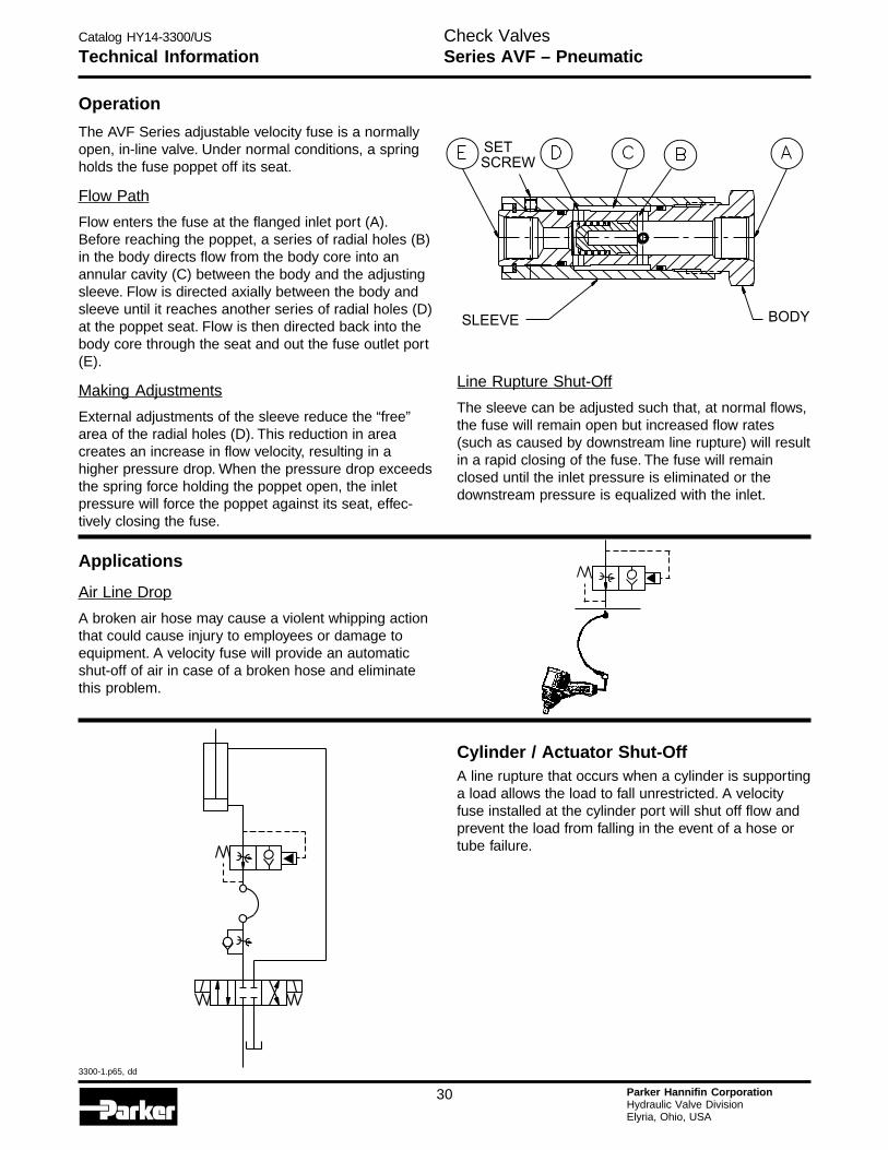
Operation
The AVF Series adjustable velocity fuse is a normallyopen, in-line valve. Under normal conditions, a springholds the fuse poppet off its seat.
Flow Path
Flow enters the fuse at the flanged inlet port (A).Before reaching the poppet, a series of radial holes (B)in the body directs flow from the body core into anannular cavity (C) between the body and the adjustingsleeve. Flow is directed axially between the body andsleeve until it reaches another series of radial holes (D)at the poppet seat. Flow is then directed back into thebody core through the seat and out the fuse outlet port(E).
Making Adjustments
External adjustments of the sleeve reduce the “free”area of the radial holes (D). This reduction in areacreates an increase in flow velocity, resulting in ahigher pressure drop. When the pressure drop exceedsthe spring force holding the poppet open, the inletpressure will force the poppet against its seat, effec-tively closing the fuse.
Line Rupture Shut-Off
The sleeve can be adjusted such that, at normal flows,the fuse will remain open but increased flow rates(such as caused by downstream line rupture) will resultin a rapid closing of the fuse. The fuse will remainclosed until the inlet pressure is eliminated or thedownstream pressure is equalized with the inlet.
SLEEVE BODY
SET
SCREW
Applications
Air Line Drop
A broken air hose may cause a violent whipping actionthat could cause injury to employees or damage toequipment. A velocity fuse will provide an automaticshut-off of air in case of a broken hose and eliminatethis problem.
Cylinder / Actuator Shut-OffA line rupture that occurs when a cylinder is supportinga load allows the load to fall unrestricted. A velocityfuse installed at the cylinder port will shut off flow andprevent the load from falling in the event of a hose ortube failure.
Catalog HY14-3300/US
3300-1.p65, dd
31 Parker Hannifin CorporationHydraulic Valve DivisionElyria, Ohio, USA
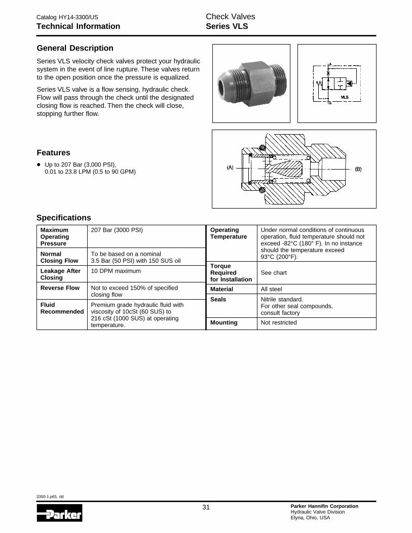
Technical InformationCheck ValvesSeries VLS
General Description
Series VLS velocity check valves protect your hydraulicsystem in the event of line rupture. These valves returnto the open position once the pressure is equalized.
Series VLS valve is a flow sensing, hydraulic check.Flow will pass through the check until the designatedclosing flow is reached. Then the check will close,stopping further flow.
Features
• Up to 207 Bar (3,000 PSI),0.01 to 23.8 LPM (0.5 to 90 GPM)
SpecificationsMaximum 207 Bar (3000 PSI)OperatingPressure
Normal To be based on a nominalClosing Flow 3.5 Bar (50 PSI) with 150 SUS oil
Leakage After 10 DPM maximumClosing
Reverse Flow Not to exceed 150% of specifiedclosing flow
Fluid Premium grade hydraulic fluid withRecommended viscosity of 10cSt (60 SUS) to
216 cSt (1000 SUS) at operatingtemperature.
Operating Under normal conditions of continuousTemperature operation, fluid temperature should not
exceed -82°C (180° F). In no instanceshould the temperature exceed93°C (200°F).
TorqueRequired See chartfor Installation
Material All steel
Seals Nitrile standard.For other seal compounds,consult factory
Mounting Not restricted
Catalog HY14-3300/US
3300-1.p65, dd
32 Parker Hannifin CorporationHydraulic Valve DivisionElyria, Ohio, USA
H
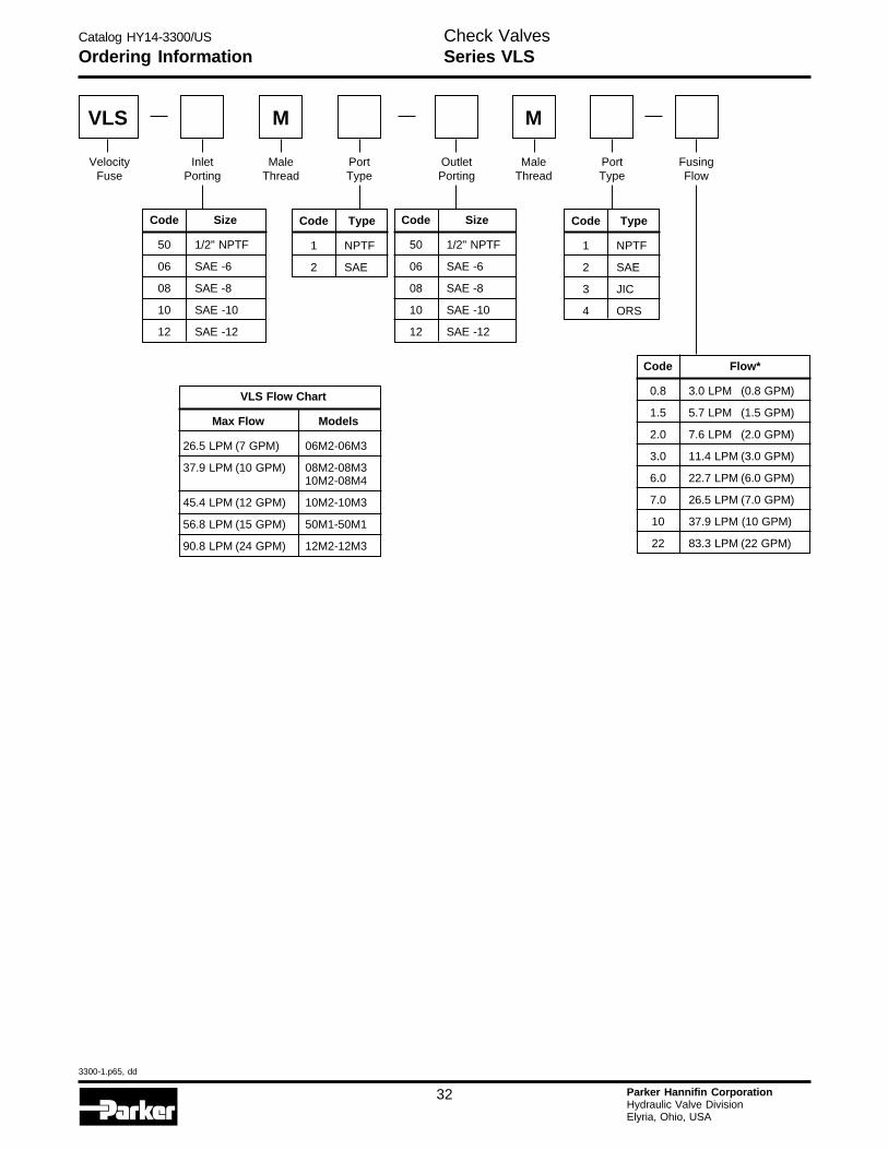
MaleThread
InletPorting
PortType
OutletPorting
M
MaleThread
PortType
Code Type
1 NPTF
2 SAE
M
FusingFlow
Code Flow*
0.8 3.0 LPM (0.8 GPM)
1.5 5.7 LPM (1.5 GPM)
2.0 7.6 LPM (2.0 GPM)
3.0 11.4 LPM (3.0 GPM)
6.0 22.7 LPM (6.0 GPM)
7.0 26.5 LPM (7.0 GPM)
10 37.9 LPM (10 GPM)
22 83.3 LPM (22 GPM)
Code Type
1 NPTF
2 SAE
3 JIC
4 ORS
Code Size
50 1/2" NPTF
06 SAE -6
08 SAE -8
10 SAE -10
12 SAE -12
Code Size
50 1/2" NPTF
06 SAE -6
08 SAE -8
10 SAE -10
12 SAE -12
VLS Flow Chart
Max Flow Models
26.5 LPM (7 GPM) 06M2-06M3
37.9 LPM (10 GPM) 08M2-08M310M2-08M4
45.4 LPM (12 GPM) 10M2-10M3
56.8 LPM (15 GPM) 50M1-50M1
90.8 LPM (24 GPM) 12M2-12M3
Ordering Information
VelocityFuse
VLS
Check ValvesSeries VLS
Catalog HY14-3300/US
3300-1.p65, dd
33 Parker Hannifin CorporationHydraulic Valve DivisionElyria, Ohio, USA
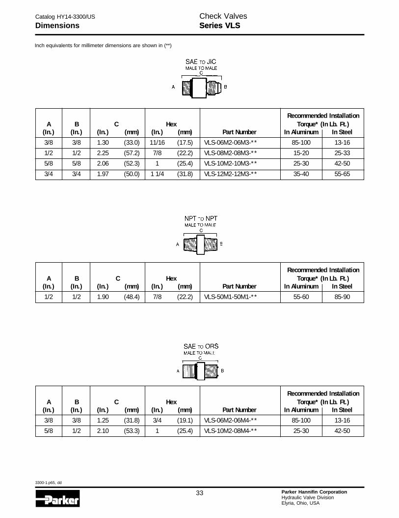
Recommended InstallationA B C Hex Torque* (In Lb. Ft.)
(In.) (In.) (In.) (mm) (In.) (mm) Part Number In Aluminum In Steel
3/8 3/8 1.30 (33.0) 11/16 (17.5) VLS-06M2-06M3-** 85-100 13-16
1/2 1/2 2.25 (57.2) 7/8 (22.2) VLS-08M2-08M3-** 15-20 25-33
5/8 5/8 2.06 (52.3) 1 (25.4) VLS-10M2-10M3-** 25-30 42-50
3/4 3/4 1.97 (50.0) 1 1/4 (31.8) VLS-12M2-12M3-** 35-40 55-65
Recommended InstallationA B C Hex Torque* (In Lb. Ft.)
(In.) (In.) (In.) (mm) (In.) (mm) Part Number In Aluminum In Steel
1/2 1/2 1.90 (48.4) 7/8 (22.2) VLS-50M1-50M1-** 55-60 85-90
Recommended InstallationA B C Hex Torque* (In Lb. Ft.)
(In.) (In.) (In.) (mm) (In.) (mm) Part Number In Aluminum In Steel
3/8 3/8 1.25 (31.8) 3/4 (19.1) VLS-06M2-06M4-** 85-100 13-16
5/8 1/2 2.10 (53.3) 1 (25.4) VLS-10M2-08M4-** 25-30 42-50
Series VLSDimensions
Inch equivalents for millimeter dimensions are shown in (**)
Check ValvesSeries VLS
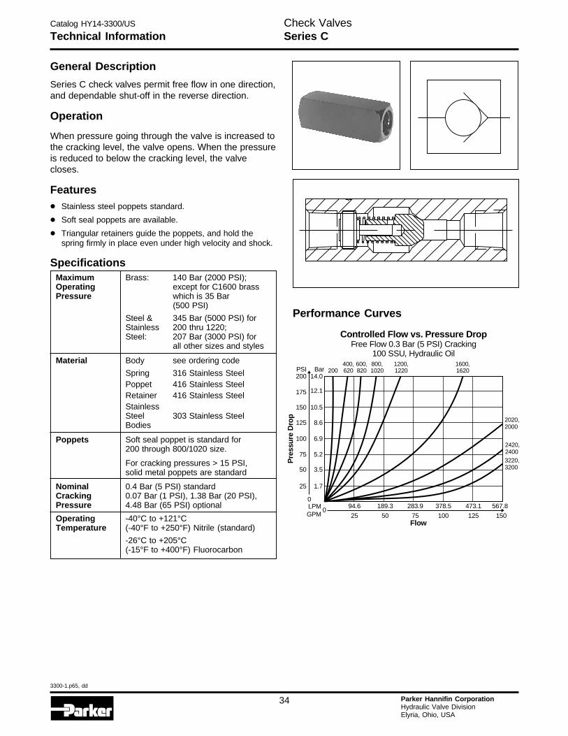
Catalog HY14-3300/US
3300-1.p65, dd
34 Parker Hannifin CorporationHydraulic Valve DivisionElyria, Ohio, USA
H
General Description
Series C check valves permit free flow in one direction,and dependable shut-off in the reverse direction.
Operation
When pressure going through the valve is increased tothe cracking level, the valve opens. When the pressureis reduced to below the cracking level, the valvecloses.
Features
• Stainless steel poppets standard.
• Soft seal poppets are available.
• Triangular retainers guide the poppets, and hold thespring firmly in place even under high velocity and shock.
SpecificationsMaximum Brass: 140 Bar (2000 PSI);Operating except for C1600 brassPressure which is 35 Bar
(500 PSI)
Steel & 345 Bar (5000 PSI) forStainless 200 thru 1220;Steel: 207 Bar (3000 PSI) for
all other sizes and styles
Material Body see ordering code
Spring 316 Stainless SteelPoppet 416 Stainless SteelRetainer 416 Stainless SteelStainlessSteel 303 Stainless SteelBodies
Poppets Soft seal poppet is standard for200 through 800/1020 size.
For cracking pressures > 15 PSI,solid metal poppets are standard
Nominal 0.4 Bar (5 PSI) standardCracking 0.07 Bar (1 PSI), 1.38 Bar (20 PSI),Pressure 4.48 Bar (65 PSI) optional
Operating -40°C to +121°CTemperature (-40°F to +250°F) Nitrile (standard)
-26°C to +205°C(-15°F to +400°F) Fluorocarbon
Performance Curves
Controlled Flow vs. Pressure DropFree Flow 0.3 Bar (5 PSI) Cracking
100 SSU, Hydraulic Oil
0283.9 378.5 473.1189.3
75 100 12550
567.8
150
94.6
25Flow
Pre
ssur
e D
rop
LPMGPM
0
25 1.7
50 3.5
75 5.2
125
150
100
8.6
10.5
6.9
175
200PSI
12.1
14.0Bar 200
400,620
600,820
800,1020
1200,1220
1600,1620
2020,2000
2420,24003220,3200
Technical InformationCheck ValvesSeries C
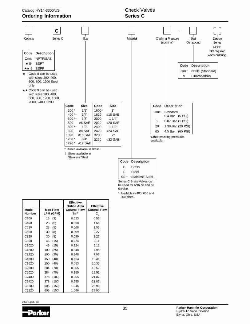
Catalog HY14-3300/US
3300-1.p65, dd
35 Parker Hannifin CorporationHydraulic Valve DivisionElyria, Ohio, USA
Ordering InformationCheck ValvesSeries C
EffectiveOrifice Area Effective
Model Max Flow Control Flow Control FlowNumber LPM (GPM) in.2 Cv
C200 15 (3) 0.023 0.53
C400 23 (5) 0.068 1.56
C620 23 (5) 0.068 1.56
C600 30 (8) 0.099 2.27
C820 30 (8) 0.099 2.27
C800 45 (15) 0.224 5.11
C1020 45 (15) 0.224 5.11
C1200 100 (25) 0.348 7.95
C1220 100 (25) 0.348 7.95
C1600 150 (40) 0.453 10.35
C1620 150 (40) 0.453 10.35
C2000 284 (70) 0.855 19.52
C2020 284 (70) 0.855 19.52
C2400 378 (100) 0.955 21.82
C2420 378 (100) 0.955 21.82
C3200 605 (150) 1.046 23.90
C3220 605 (150) 1.046 23.90
Code Description
Omit Nitrile (Standard)
V Fluorocarbon
Code Description
Omit NPTF/SAE
★ 8 BSPT
★★ 9 BSPP
DesignSeriesNOTE:
Not requiredwhen ordering.
Options Series C Size Material Cracking Pressure(nominal)
SealCompound
C
* Sizes available in Brass
† Sizes available inStainless Steel
200 * 1/8"400 *† 1/4"600 *† 3/8"620 #6 SAE800 *† 1/2"820 #8 SAE
1020 #10 SAE1200 * 3/4"1220 * #12 SAE
1600 * 1"1620 #16 SAE2000 1 1/4"2020 #20 SAE2400 1 1/2"2420 #24 SAE3200 2"3220 #32 SAE
Code Size Code Size
Code Description
B Brass
S Steel
SS * Stainless SteelSeries C Brass Valves canbe used for both air and oilservice.
* Available in 400, 600 and800 sizes.
Code Description
Omit Standard0.4 Bar (5 PSI)
1 0.07 Bar (1 PSI)
20 1.38 Bar (20 PSI)
65 4.5 Bar (65 PSI)
Other cracking pressuresavailable.
★ Code 8 can be usedwith sizes 200, 400,600, 800, 1200 Steelonly
★★ Code 9 can be usedwith sizes 200, 400,600, 800, 1200, 1600,2000, 2400, 3200
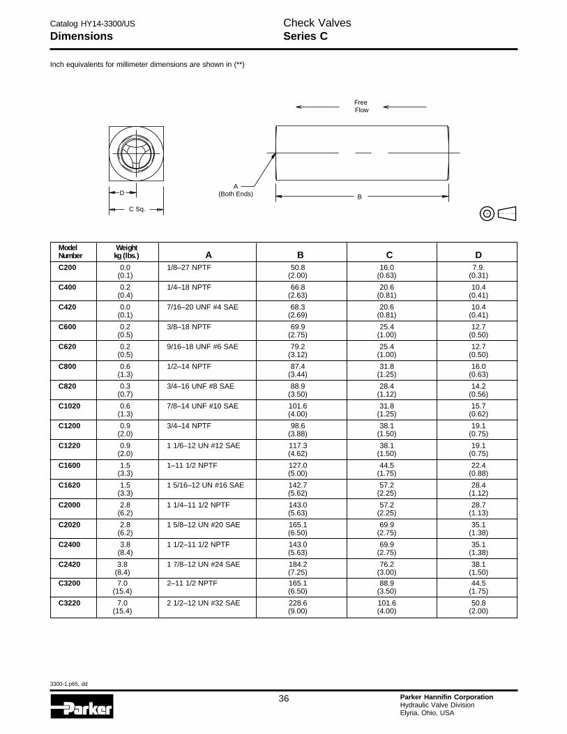
Catalog HY14-3300/US
3300-1.p65, dd
36 Parker Hannifin CorporationHydraulic Valve DivisionElyria, Ohio, USA
H
Model WeightNumber kg (lbs.) A B C DC200 0.0 1/8–27 NPTF 50.8 16.0 7.9.
(0.1) (2.00) (0.63) (0.31)
C400 0.2 1/4–18 NPTF 66.8 20.6 10.4(0.4) (2.63) (0.81) (0.41)
C420 0.0 7/16–20 UNF #4 SAE 68.3 20.6 10.4(0.1) (2.69) (0.81) (0.41)
C600 0.2 3/8–18 NPTF 69.9 25.4 12.7(0.5) (2.75) (1.00) (0.50)
C620 0.2 9/16–18 UNF #6 SAE 79.2 25.4 12.7(0.5) (3.12) (1.00) (0.50)
C800 0.6 1/2–14 NPTF 87.4 31.8 16.0(1.3) (3.44) (1.25) (0.63)
C820 0.3 3/4–16 UNF #8 SAE 88.9 28.4 14.2(0.7) (3.50) (1.12) (0.56)
C1020 0.6 7/8–14 UNF #10 SAE 101.6 31.8 15.7(1.3) (4.00) (1.25) (0.62)
C1200 0.9 3/4–14 NPTF 98.6 38.1 19.1(2.0) (3.88) (1.50) (0.75)
C1220 0.9 1 1/6–12 UN #12 SAE 117.3 38.1 19.1(2.0) (4.62) (1.50) (0.75)
C1600 1.5 1–11 1/2 NPTF 127.0 44.5 22.4(3.3) (5.00) (1.75) (0.88)
C1620 1.5 1 5/16–12 UN #16 SAE 142.7 57.2 28.4(3.3) (5.62) (2.25) (1.12)
C2000 2.8 1 1/4–11 1/2 NPTF 143.0 57.2 28.7(6.2) (5.63) (2.25) (1.13)
C2020 2.8 1 5/8–12 UN #20 SAE 165.1 69.9 35.1(6.2) (6.50) (2.75) (1.38)
C2400 3.8 1 1/2–11 1/2 NPTF 143.0 69.9 35.1(8.4) (5.63) (2.75) (1.38)
C2420 3.8 1 7/8–12 UN #24 SAE 184.2 76.2 38.1(8.4) (7.25) (3.00) (1.50)
C3200 7.0 2–11 1/2 NPTF 165.1 88.9 44.5(15.4) (6.50) (3.50) (1.75)
C3220 7.0 2 1/2–12 UN #32 SAE 228.6 101.6 50.8(15.4) (9.00) (4.00) (2.00)
Inch equivalents for millimeter dimensions are shown in (**)
A(Both Ends)D
C Sq.
FreeFlow
B
DimensionsCheck ValvesSeries C
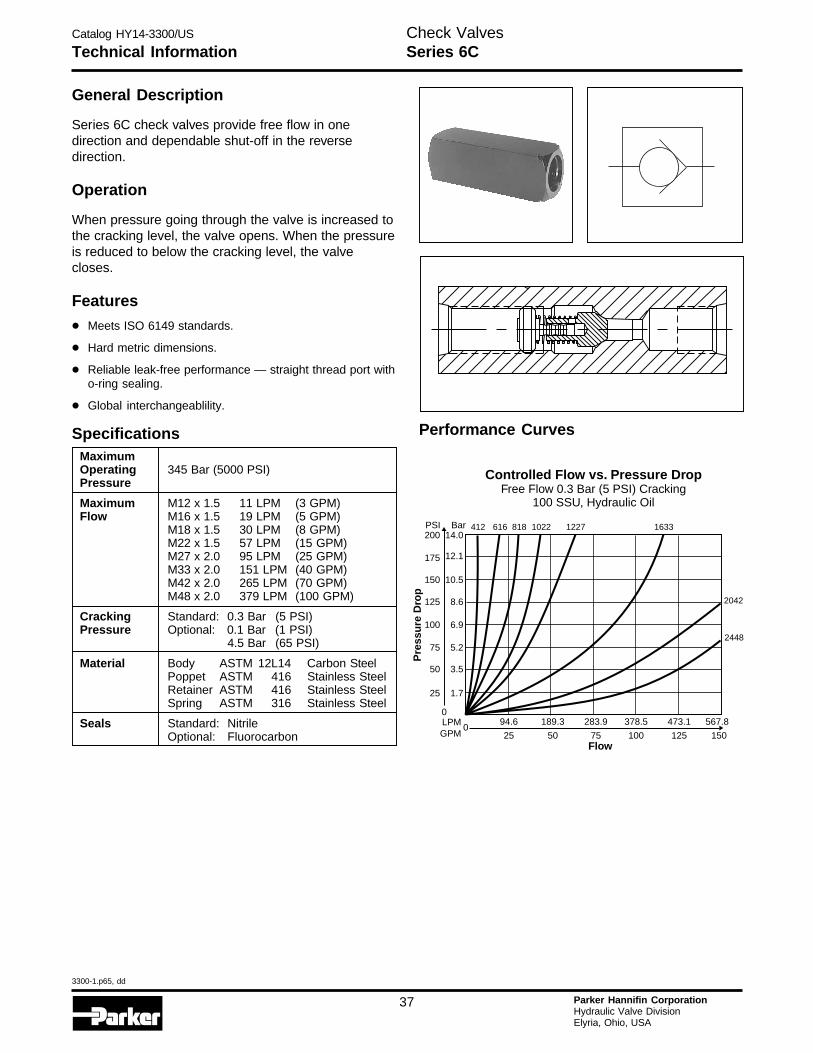
Catalog HY14-3300/US
3300-1.p65, dd
37 Parker Hannifin CorporationHydraulic Valve DivisionElyria, Ohio, USA
Technical InformationCheck ValvesSeries 6C
General Description
Series 6C check valves provide free flow in onedirection and dependable shut-off in the reversedirection.
Operation
When pressure going through the valve is increased tothe cracking level, the valve opens. When the pressureis reduced to below the cracking level, the valvecloses.
Features
• Meets ISO 6149 standards.
• Hard metric dimensions.
• Reliable leak-free performance — straight thread port witho-ring sealing.
• Global interchangeablility.
SpecificationsMaximumOperating 345 Bar (5000 PSI)Pressure
Maximum M12 x 1.5 11 LPM (3 GPM)Flow M16 x 1.5 19 LPM (5 GPM)
M18 x 1.5 30 LPM (8 GPM)M22 x 1.5 57 LPM (15 GPM)M27 x 2.0 95 LPM (25 GPM)M33 x 2.0 151 LPM (40 GPM)M42 x 2.0 265 LPM (70 GPM)M48 x 2.0 379 LPM (100 GPM)
Cracking Standard: 0.3 Bar (5 PSI)Pressure Optional: 0.1 Bar (1 PSI)
4.5 Bar (65 PSI)
Material Body ASTM 12L14 Carbon SteelPoppet ASTM 416 Stainless SteelRetainer ASTM 416 Stainless SteelSpring ASTM 316 Stainless Steel
Seals Standard: NitrileOptional: Fluorocarbon
Performance Curves
Controlled Flow vs. Pressure DropFree Flow 0.3 Bar (5 PSI) Cracking
100 SSU, Hydraulic Oil
0283.9 378.5 473.1189.3
75 100 12550
567.8
150
94.6
25Flow
Pre
ssu
re D
rop
LPMGPM
0
25 1.7
50 3.5
75 5.2
125
150
100
8.6
10.5
6.9
175
200PSI
12.1
14.0Bar 412 616 818 1022 1227 1633
2042
2448
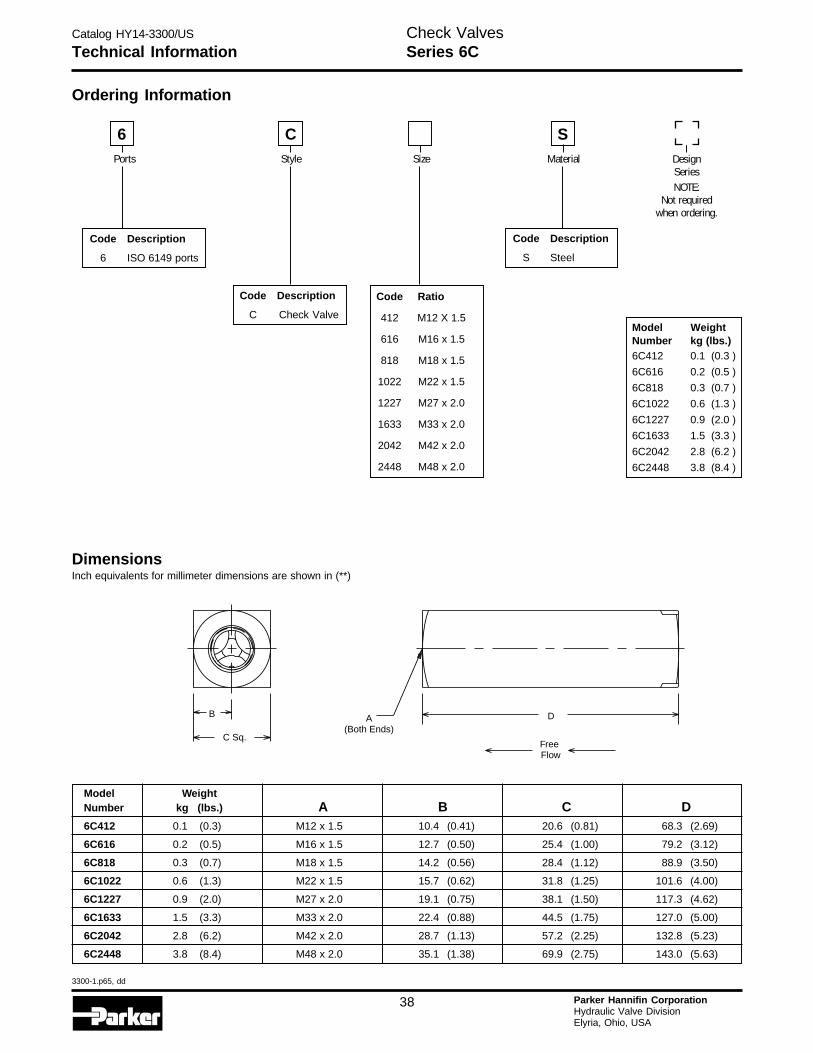
Catalog HY14-3300/US
3300-1.p65, dd
38 Parker Hannifin CorporationHydraulic Valve DivisionElyria, Ohio, USA
H
Technical InformationCheck ValvesSeries 6C
DimensionsInch equivalents for millimeter dimensions are shown in (**)
Model WeightNumber kg (lbs.) A B C D6C412 0.1 (0.3) M12 x 1.5 10.4 (0.41) 20.6 (0.81) 68.3 (2.69)
6C616 0.2 (0.5) M16 x 1.5 12.7 (0.50) 25.4 (1.00) 79.2 (3.12)
6C818 0.3 (0.7) M18 x 1.5 14.2 (0.56) 28.4 (1.12) 88.9 (3.50)
6C1022 0.6 (1.3) M22 x 1.5 15.7 (0.62) 31.8 (1.25) 101.6 (4.00)
6C1227 0.9 (2.0) M27 x 2.0 19.1 (0.75) 38.1 (1.50) 117.3 (4.62)
6C1633 1.5 (3.3) M33 x 2.0 22.4 (0.88) 44.5 (1.75) 127.0 (5.00)
6C2042 2.8 (6.2) M42 x 2.0 28.7 (1.13) 57.2 (2.25) 132.8 (5.23)
6C2448 3.8 (8.4) M48 x 2.0 35.1 (1.38) 69.9 (2.75) 143.0 (5.63)
A(Both Ends)
D
C Sq.FreeFlow
B
Code Description
S Steel
Code Description
C Check Valve
Code Description
6 ISO 6149 ports
Code Ratio
412 M12 X 1.5
616 M16 x 1.5
818 M18 x 1.5
1022 M22 x 1.5
1227 M27 x 2.0
1633 M33 x 2.0
2042 M42 x 2.0
2448 M48 x 2.0
DesignSeriesNOTE:
Not requiredwhen ordering.
Ports Style
6 CMaterial
SSize
Model WeightNumber kg (lbs.)6C412 0.1 (0.3 )
6C616 0.2 (0.5 )
6C818 0.3 (0.7 )
6C1022 0.6 (1.3 )
6C1227 0.9 (2.0 )
6C1633 1.5 (3.3 )
6C2042 2.8 (6.2 )
6C2448 3.8 (8.4 )
Ordering Information
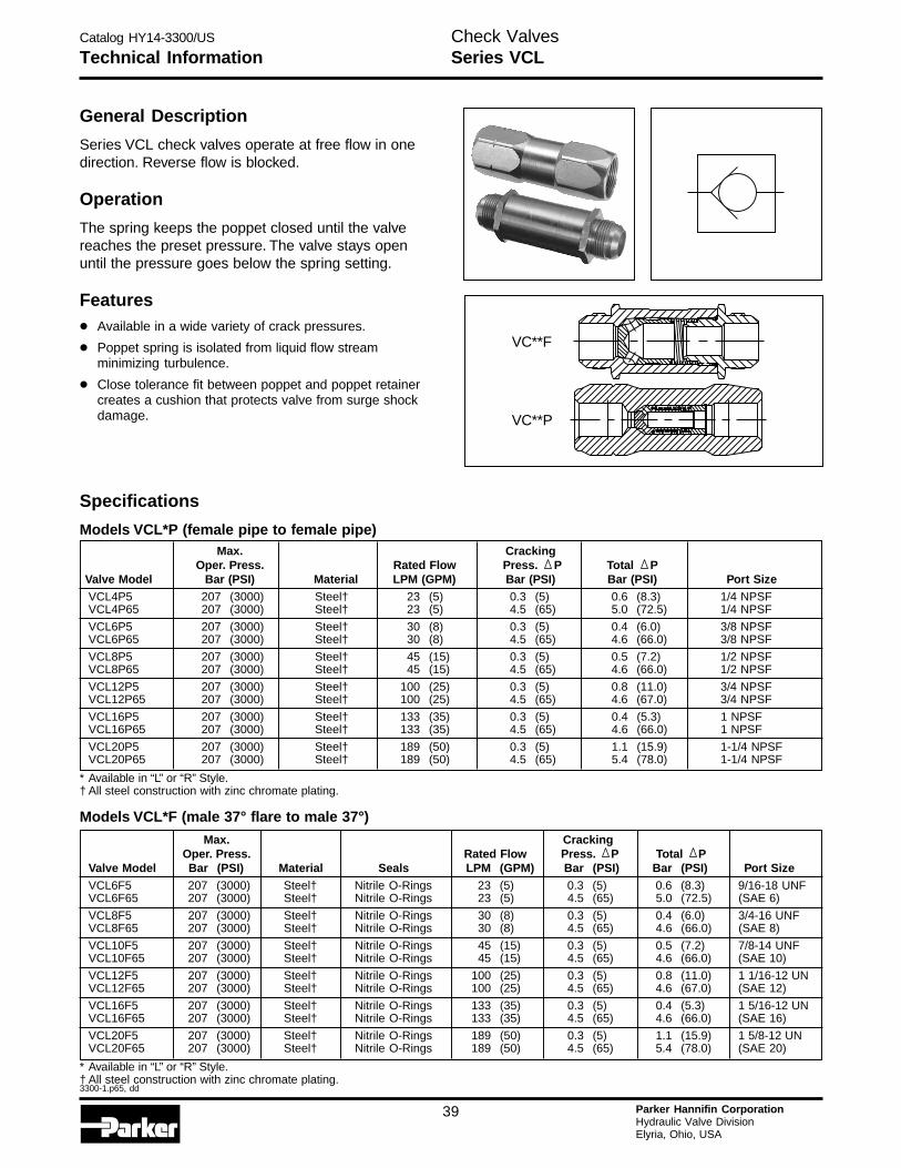
Catalog HY14-3300/US
3300-1.p65, dd
39 Parker Hannifin CorporationHydraulic Valve DivisionElyria, Ohio, USA
Technical InformationCheck ValvesSeries VCL
General Description
Series VCL check valves operate at free flow in onedirection. Reverse flow is blocked.
Operation
The spring keeps the poppet closed until the valvereaches the preset pressure. The valve stays openuntil the pressure goes below the spring setting.
Features
• Available in a wide variety of crack pressures.
• Poppet spring is isolated from liquid flow streamminimizing turbulence.
• Close tolerance fit between poppet and poppet retainercreates a cushion that protects valve from surge shockdamage.
Max. CrackingOper. Press. Rated Flow Press. P Total P
Valve Model Bar (PSI) Material LPM (GPM) Bar (PSI) Bar (PSI) Port SizeVCL4P5 207 (3000) Steel† 23 (5) 0.3 (5) 0.6 (8.3) 1/4 NPSFVCL4P65 207 (3000) Steel† 23 (5) 4.5 (65) 5.0 (72.5) 1/4 NPSF
VCL6P5 207 (3000) Steel† 30 (8) 0.3 (5) 0.4 (6.0) 3/8 NPSFVCL6P65 207 (3000) Steel† 30 (8) 4.5 (65) 4.6 (66.0) 3/8 NPSF
VCL8P5 207 (3000) Steel† 45 (15) 0.3 (5) 0.5 (7.2) 1/2 NPSFVCL8P65 207 (3000) Steel† 45 (15) 4.5 (65) 4.6 (66.0) 1/2 NPSF
VCL12P5 207 (3000) Steel† 100 (25) 0.3 (5) 0.8 (11.0) 3/4 NPSFVCL12P65 207 (3000) Steel† 100 (25) 4.5 (65) 4.6 (67.0) 3/4 NPSF
VCL16P5 207 (3000) Steel† 133 (35) 0.3 (5) 0.4 (5.3) 1 NPSFVCL16P65 207 (3000) Steel† 133 (35) 4.5 (65) 4.6 (66.0) 1 NPSF
VCL20P5 207 (3000) Steel† 189 (50) 0.3 (5) 1.1 (15.9) 1-1/4 NPSFVCL20P65 207 (3000) Steel† 189 (50) 4.5 (65) 5.4 (78.0) 1-1/4 NPSF
* Available in “L” or “R” Style.† All steel construction with zinc chromate plating.
Max. CrackingOper. Press. Rated Flow Press. P Total P
Valve Model Bar (PSI) Material Seals LPM (GPM) Bar (PSI) Bar (PSI) Port SizeVCL6F5 207 (3000) Steel† Nitrile O-Rings 23 (5) 0.3 (5) 0.6 (8.3) 9/16-18 UNFVCL6F65 207 (3000) Steel† Nitrile O-Rings 23 (5) 4.5 (65) 5.0 (72.5) (SAE 6)
VCL8F5 207 (3000) Steel† Nitrile O-Rings 30 (8) 0.3 (5) 0.4 (6.0) 3/4-16 UNFVCL8F65 207 (3000) Steel† Nitrile O-Rings 30 (8) 4.5 (65) 4.6 (66.0) (SAE 8)
VCL10F5 207 (3000) Steel† Nitrile O-Rings 45 (15) 0.3 (5) 0.5 (7.2) 7/8-14 UNFVCL10F65 207 (3000) Steel† Nitrile O-Rings 45 (15) 4.5 (65) 4.6 (66.0) (SAE 10)
VCL12F5 207 (3000) Steel† Nitrile O-Rings 100 (25) 0.3 (5) 0.8 (11.0) 1 1/16-12 UNVCL12F65 207 (3000) Steel† Nitrile O-Rings 100 (25) 4.5 (65) 4.6 (67.0) (SAE 12)
VCL16F5 207 (3000) Steel† Nitrile O-Rings 133 (35) 0.3 (5) 0.4 (5.3) 1 5/16-12 UNVCL16F65 207 (3000) Steel† Nitrile O-Rings 133 (35) 4.5 (65) 4.6 (66.0) (SAE 16)
VCL20F5 207 (3000) Steel† Nitrile O-Rings 189 (50) 0.3 (5) 1.1 (15.9) 1 5/8-12 UNVCL20F65 207 (3000) Steel† Nitrile O-Rings 189 (50) 4.5 (65) 5.4 (78.0) (SAE 20)
* Available in “L” or “R” Style.† All steel construction with zinc chromate plating.
Specifications
Models VCL*P (female pipe to female pipe)
VC**F
VC**P
Models VCL*F (male 37° flare to male 37°)
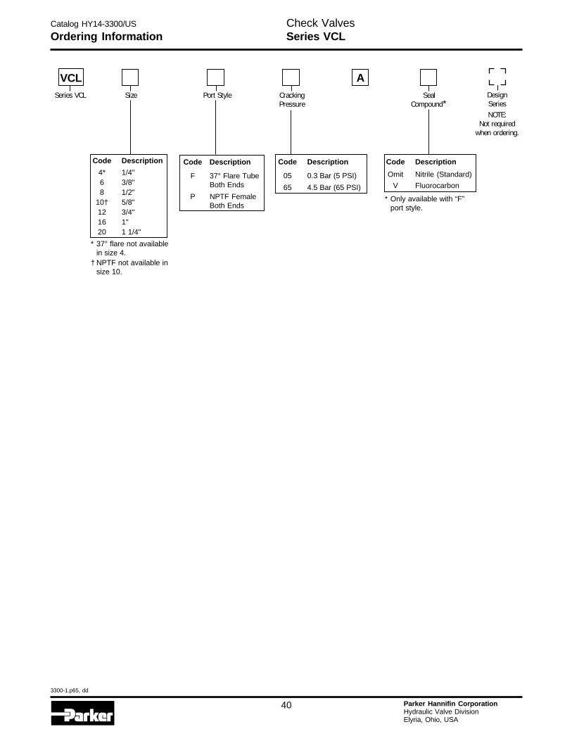
Catalog HY14-3300/US
3300-1.p65, dd
40 Parker Hannifin CorporationHydraulic Valve DivisionElyria, Ohio, USA
H
Ordering InformationCheck ValvesSeries VCL
Code Description
4* 1/4"6 3/8"8 1/2"
10† 5/8"12 3/4"16 1"20 1 1/4"
* 37° flare not availablein size 4.
† NPTF not available insize 10.
Code Description
F 37° Flare TubeBoth Ends
P NPTF FemaleBoth Ends
Code Description
05 0.3 Bar (5 PSI)
65 4.5 Bar (65 PSI)
Code Description
Omit Nitrile (Standard)
V Fluorocarbon
DesignSeriesNOTE:
Not requiredwhen ordering.
* Only available with “F”port style.
SealCompound*
ACrackingPressure
Port StyleSizeSeries VCL
VCL
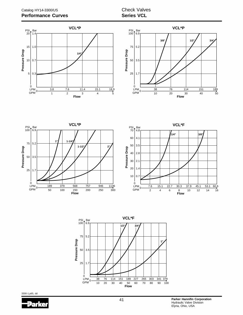
Catalog HY14-3300/US
3300-1.p65, dd
41 Parker Hannifin CorporationHydraulic Valve DivisionElyria, Ohio, USA
VCL*P
011.4 15.17.6
3 42
18.9
5
3.8
1Flow
Pre
ssu
re D
rop
LPMGPM
0
5 0.3
15
10
1.0
0.7
20PSI
1.4Bar
1/4"
VCL*P
0114 15176
30 4020
189
50
38
10Flow
Pre
ssu
re D
rop
LPMGPM
0
25 1.7
75
50
5.2
3.5
100PSI
6.9Bar
3/8" 1/2" 3/4"
VCL*P
0757 946568
200 250150
1136
300
189 379
50 100Flow
Pre
ssu
re D
rop
LPMGPM
0
25 1.7
75
50
5.2
3.5
100PSI
6.9Bar
1-1/4"1"
2"1-1/2"
VCL*F
037.930.3 45.1 53.122.715.1
108 12 1464
60.6
16
7.6
2Flow
Pre
ssu
re D
rop
LPMGPM
0
20
30
10
1.4
2.1
0.7
60
50
40
4.1
3.5
2.8
70PSI
4.8Bar
1/4" 3/8"
VCL*F
0265227 303 341189151
7060 80 905040
379
100
7638 114
2010 30Flow
Pre
ssu
re D
rop
LPMGPM
0
25 1.7
75
50
5.2
3.5
100PSI
6.9Bar
1"
1/2" 3/4"
Performance CurvesCheck ValvesSeries VCL
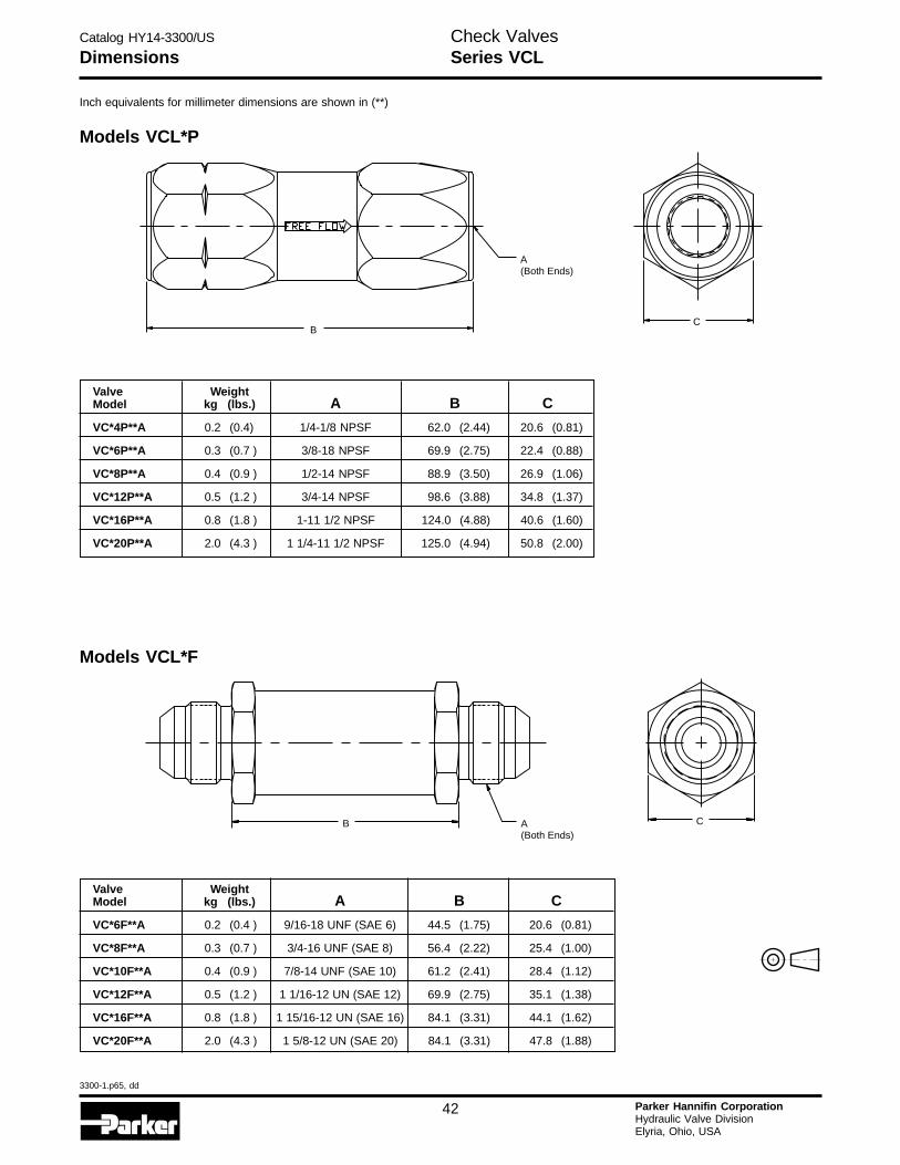
Catalog HY14-3300/US
3300-1.p65, dd
42 Parker Hannifin CorporationHydraulic Valve DivisionElyria, Ohio, USA
H
Models VCL*P
Models VCL*F
Valve WeightModel kg (lbs.) A B C
VC*4P**A 0.2 (0.4) 1/4-1/8 NPSF 62.0 (2.44) 20.6 (0.81)
VC*6P**A 0.3 (0.7 ) 3/8-18 NPSF 69.9 (2.75) 22.4 (0.88)
VC*8P**A 0.4 (0.9 ) 1/2-14 NPSF 88.9 (3.50) 26.9 (1.06)
VC*12P**A 0.5 (1.2 ) 3/4-14 NPSF 98.6 (3.88) 34.8 (1.37)
VC*16P**A 0.8 (1.8 ) 1-11 1/2 NPSF 124.0 (4.88) 40.6 (1.60)
VC*20P**A 2.0 (4.3 ) 1 1/4-11 1/2 NPSF 125.0 (4.94) 50.8 (2.00)
Valve WeightModel kg (lbs.) A B C
VC*6F**A 0.2 (0.4 ) 9/16-18 UNF (SAE 6) 44.5 (1.75) 20.6 (0.81)
VC*8F**A 0.3 (0.7 ) 3/4-16 UNF (SAE 8) 56.4 (2.22) 25.4 (1.00)
VC*10F**A 0.4 (0.9 ) 7/8-14 UNF (SAE 10) 61.2 (2.41) 28.4 (1.12)
VC*12F**A 0.5 (1.2 ) 1 1/16-12 UN (SAE 12) 69.9 (2.75) 35.1 (1.38)
VC*16F**A 0.8 (1.8 ) 1 15/16-12 UN (SAE 16) 84.1 (3.31) 44.1 (1.62)
VC*20F**A 2.0 (4.3 ) 1 5/8-12 UN (SAE 20) 84.1 (3.31) 47.8 (1.88)
Inch equivalents for millimeter dimensions are shown in (**)
B
A(Both Ends)
C
B A(Both Ends)
C
DimensionsCheck ValvesSeries VCL
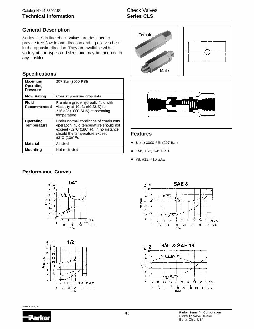
Catalog HY14-3300/US
3300-1.p65, dd
43 Parker Hannifin CorporationHydraulic Valve DivisionElyria, Ohio, USA
Technical InformationCheck ValvesSeries CLS
General Description
Series CLS in-line check valves are designed toprovide free flow in one direction and a positive checkin the opposite direction. They are available with avariety of port types and sizes and may be mounted inany position.
Specifications
Female
Male
Performance Curves
Features
• Up to 3000 PSI (207 Bar)
• 1/4", 1/2", 3/4" NPTF
• #8, #12, #16 SAE
Maximum 207 Bar (3000 PSI)OperatingPressure
Flow Rating Consult pressure drop data
Fluid Premium grade hydraulic fluid withRecommended viscosity of 10cSt (60 SUS) to
216 cSt (1000 SUS) at operatingtemperature.
Operating Under normal conditions of continuousTemperature operation, fluid temperature should not
exceed -82°C (180° F). In no instanceshould the temperature exceed93°C (200°F).
Material All steel
Mounting Not restricted
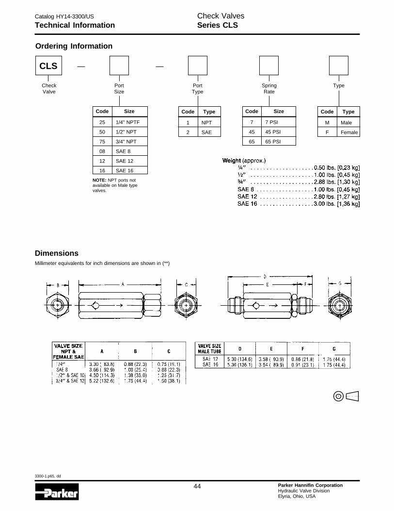
Catalog HY14-3300/US
3300-1.p65, dd
44 Parker Hannifin CorporationHydraulic Valve DivisionElyria, Ohio, USA
H
Technical Information
DimensionsMillimeter equivalents for inch dimensions are shown in (**)
Ordering Information
Type
Code Type
M Male
F Female
SpringRate
Code Size
7 7 PSI
45 45 PSI
65 65 PSI
PortType
Code Type
1 NPT
2 SAE
PortSize
Code Size
25 1/4" NPTF
50 1/2" NPT
75 3/4" NPT
08 SAE 8
12 SAE 12
16 SAE 16
NOTE: NPT ports notavailable on Male typevalves.
CheckValve
CLS
Check ValvesSeries CLS
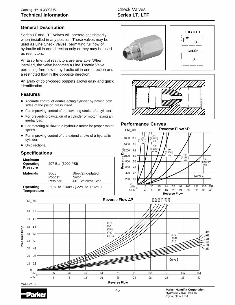
Catalog HY14-3300/US
3300-1.p65, dd
45 Parker Hannifin CorporationHydraulic Valve DivisionElyria, Ohio, USA
Technical InformationCheck ValvesSeries LT, LTF
General Description
Series LT and LTF Valves will operate satisfactorilywhen installed in any position. These valves may beused as Line Check Valves, permitting full flow ofhydraulic oil in one direction only or they may be usedas restrictors.
An assortment of restrictors are available. Wheninstalled, the valve becomes a Line Throttle Valvepermitting free flow of hydraulic oil in one direction anda restricted flow in the opposite direction.
An array of color-coded poppets allows easy and quickidentification.
Features
• Accurate control of double-acting cylinder by having bothsides of the piston pressurized.
• For improving control of the lowering stroke of a cylinder.
• For preventing cavitation of a cylinder or motor having aninertia load.
• For metering oil flow to a hydraulic motor for proper motorspeed.
• For improving control of the extend stroke of a hydrauliccylinder.
• Unidirectional.
Specifications
Performance Curves
MaximumOperating 207 Bar (3000 PSI)Pressure
Materials Body: Steel/Zinc-platedPoppet: NylonRetainer: 416 Stainless Steel
Operating -30°C to +100°C (-22°F to +212°F)Temperature
Reverse Flow P
0308
4512
6116
154
9124
10628
12132
13636
Reverse Flow
0
200 13
600 41
1000 69
1200 82
1400
1600
PSI
96
110
Bar
Pre
ssu
re D
rop
LPMGPM
800 55
400 27
2076
40151
Curve 1
1.6(0.062")
Hole
2.4(0.095")
Hole
3.2(0.125")
Hole4.0
(0.156")Hole 4.8
(0.189")Hole 5.6
(0.220")Hole
Pre
ssu
re D
rop
030
8
45
12
61
16
15
4
91
24
106
28
121
32
136
36
0
10 0.6
30 41
50 69
60 4.1
70
80
PSI
4.8
5.5
Bar
LPMGPM
40 55
20 27
20
76
40
151
000095125156189220
000
062
095
125
156
189
LT-75LTF-12LT-12
LT-50LT-8LTF-8LT-10LTF-10
Curve 2
Reverse Flow
Reverse Flow P
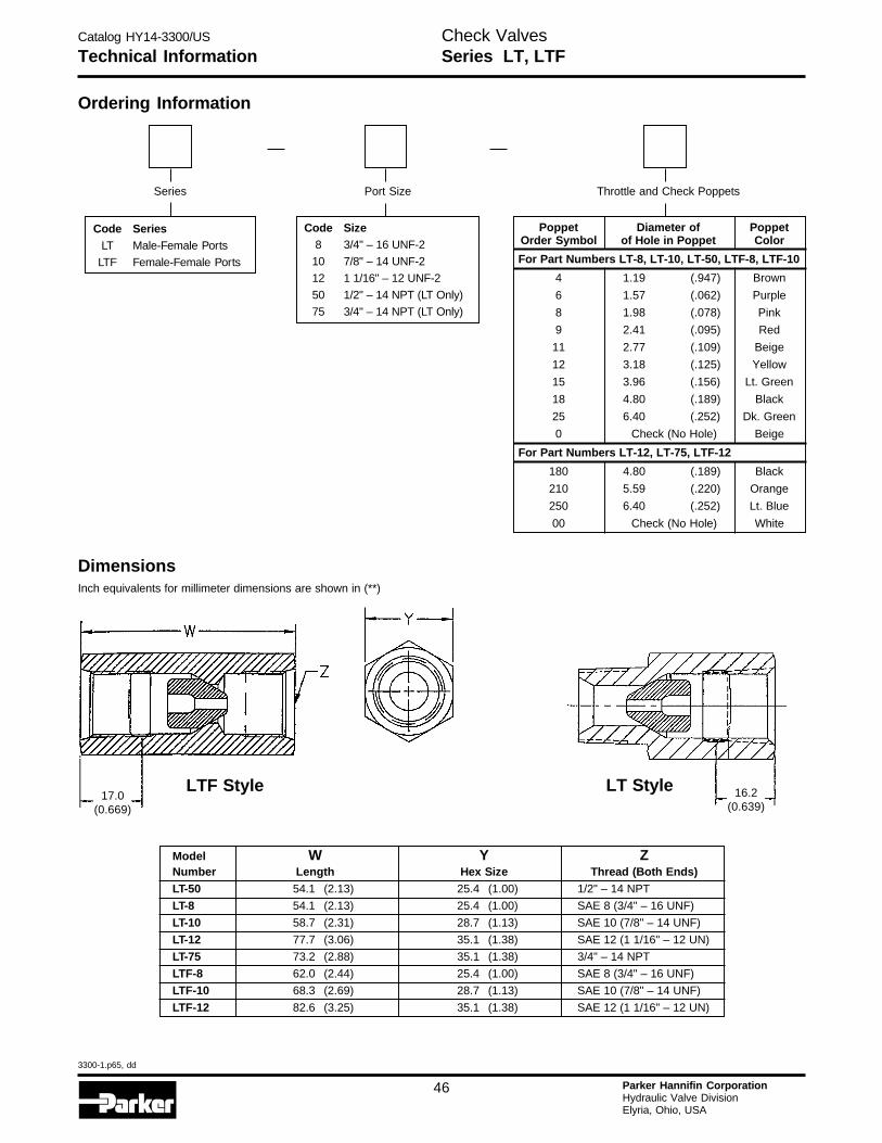
Catalog HY14-3300/US
3300-1.p65, dd
46 Parker Hannifin CorporationHydraulic Valve DivisionElyria, Ohio, USA
H
Technical InformationCheck ValvesSeries LT, LTF
Ordering Information
Throttle and Check Poppets
Poppet Diameter of PoppetOrder Symbol of Hole in Poppet Color
For Part Numbers LT-8, LT-10, LT-50, LTF-8, LTF-10
4 1.19 (.947) Brown
6 1.57 (.062) Purple
8 1.98 (.078) Pink
9 2.41 (.095) Red
11 2.77 (.109) Beige
12 3.18 (.125) Yellow
15 3.96 (.156) Lt. Green
18 4.80 (.189) Black
25 6.40 (.252) Dk. Green
0 Check (No Hole) Beige
For Part Numbers LT-12, LT-75, LTF-12
180 4.80 (.189) Black
210 5.59 (.220) Orange
250 6.40 (.252) Lt. Blue
00 Check (No Hole) White
Port Size
Code Size8 3/4" – 16 UNF-2
10 7/8" – 14 UNF-2
12 1 1/16" – 12 UNF-2
50 1/2" – 14 NPT (LT Only)
75 3/4" – 14 NPT (LT Only)
Series
Code SeriesLT Male-Female Ports
LTF Female-Female Ports
DimensionsInch equivalents for millimeter dimensions are shown in (**)
LTF Style LT Style
Model W Y ZNumber Length Hex Size Thread (Both Ends)LT-50 54.1 (2.13) 25.4 (1.00) 1/2" – 14 NPT
LT-8 54.1 (2.13) 25.4 (1.00) SAE 8 (3/4" – 16 UNF)
LT-10 58.7 (2.31) 28.7 (1.13) SAE 10 (7/8" – 14 UNF)
LT-12 77.7 (3.06) 35.1 (1.38) SAE 12 (1 1/16" – 12 UN)
LT-75 73.2 (2.88) 35.1 (1.38) 3/4" – 14 NPT
LTF-8 62.0 (2.44) 25.4 (1.00) SAE 8 (3/4" – 16 UNF)
LTF-10 68.3 (2.69) 28.7 (1.13) SAE 10 (7/8" – 14 UNF)
LTF-12 82.6 (3.25) 35.1 (1.38) SAE 12 (1 1/16" – 12 UN)
16.2(0.639)
17.0(0.669)
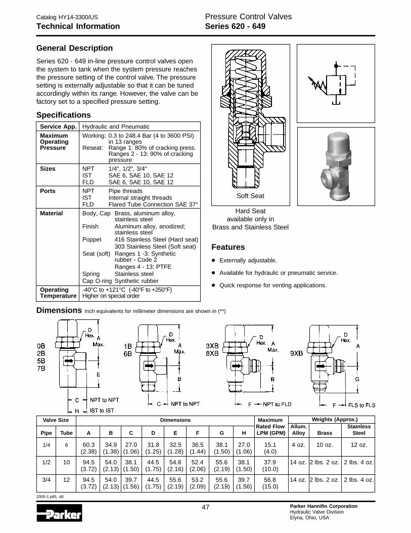
Catalog HY14-3300/US
3300-1.p65, dd
47 Parker Hannifin CorporationHydraulic Valve DivisionElyria, Ohio, USA
Technical Information
General Description
Series 620 - 649 in-line pressure control valves openthe system to tank when the system pressure reachesthe pressure setting of the control valve. The pressuresetting is externally adjustable so that it can be tunedaccordingly within its range. However, the valve can befactory set to a specified pressure setting.
Specifications
Pressure Control ValvesSeries 620 - 649
Dimensions Inch equivalents for millimeter dimensions are shown in (**)
Valve Size Dimensions Maximum Weights (Approx.)Rated Flow Allum. Stainless
Pipe Tube A B C D E F G H LPM (GPM) Alloy Brass Steel
1/4 6 60.3 34.9 27.0 31.8 32.5 36.5 38.1 27.0 15.1 4 oz. 10 oz. 12 oz.(2.38) (1.38) (1.06) (1.25) (1.28) (1.44) (1.50) (1.06) (4.0)
1/2 10 94.5 54.0 38.1 44.5 54.8 52.4 55.6 38.1 37.9 14 oz. 2 lbs. 2 oz. 2 lbs. 4 oz.(3.72) (2.13) (1.50) (1.75) (2.16) (2.06) (2.19) (1.50) (10.0)
3/4 12 94.5 54.0 39.7 44.5 55.6 53.2 55.6 39.7 56.8 14 oz. 2 lbs. 2 oz. 2 lbs. 4 oz.(3.72) (2.13) (1.56) (1.75) (2.19) (2.09) (2.19) (1.56) (15.0)
Service App. Hydraulic and Pneumatic
Maximum Working: 0.3 to 248.4 Bar (4 to 3600 PSI)Operating in 13 rangesPressure Reseat: Range 1: 80% of cracking press.
Ranges 2 - 13: 90% of crackingpressure
Sizes NPT 1/4", 1/2", 3/4"IST SAE 6, SAE 10, SAE 12FLD SAE 6, SAE 10, SAE 12
Ports NPT Pipe threadsIST Internal straight threadsFLD Flared Tube Connection SAE 37°
Material Body, Cap Brass, aluminum alloy,stainless steel
Finish Aluminum alloy, anodized;stainless steel
Poppet 416 Stainless Steel (Hard seat)303 Stainless Steel (Soft seat)
Seat (soft) Ranges 1 -3: Syntheticrubber - Code 2Ranges 4 - 13: PTFE
Spring Stainless steelCap O-ring Synthetic rubber
Operating -40°C to +121°C (-40°F to +250°F)Temperature Higher on special order
Features
• Externally adjustable.
• Available for hydraulic or pneumatic service.
• Quick response for venting applications.
Soft Seat
Hard Seatavailable only in
Brass and Stainless Steel
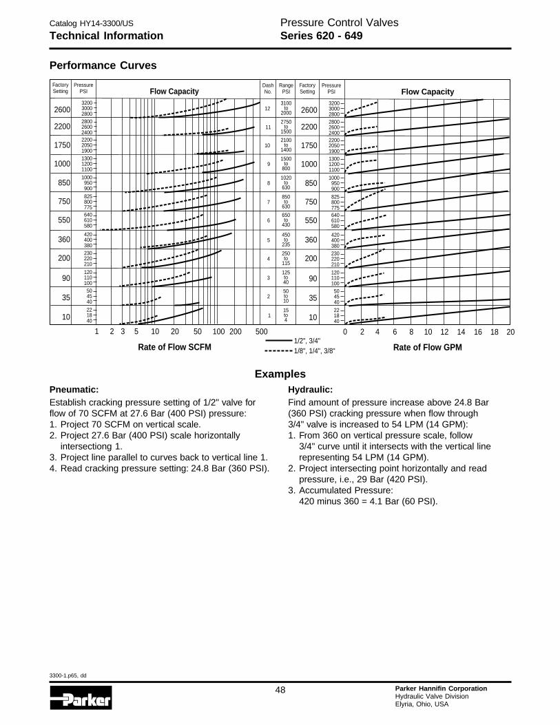
Catalog HY14-3300/US
3300-1.p65, dd
48 Parker Hannifin CorporationHydraulic Valve DivisionElyria, Ohio, USA
H
Performance Curves
Examples
Pressure Control ValvesSeries 620 - 649Technical Information
Pneumatic:Establish cracking pressure setting of 1/2" valve forflow of 70 SCFM at 27.6 Bar (400 PSI) pressure:1. Project 70 SCFM on vertical scale.2. Project 27.6 Bar (400 PSI) scale horizontally
intersectiong 1.3. Project line parallel to curves back to vertical line 1.4. Read cracking pressure setting: 24.8 Bar (360 PSI).
Hydraulic:Find amount of pressure increase above 24.8 Bar(360 PSI) cracking pressure when flow through3/4" valve is increased to 54 LPM (14 GPM):1. From 360 on vertical pressure scale, follow
3/4" curve until it intersects with the vertical linerepresenting 54 LPM (14 GPM).
2. Project intersecting point horizontally and readpressure, i.e., 29 Bar (420 PSI).
3. Accumulated Pressure:420 minus 360 = 4.1 Bar (60 PSI).
Rate of Flow SCFM Rate of Flow GPM
FactorySetting
FactorySetting
PressurePSI
PressurePSI
RangePSI
DashNo.Flow Capacity Flow Capacity
2600 26003200 32003100
to2000
2750to
1500
2100to
1400
1500to
800
1020to
630
850to
630
650to
430
450to
235
250to
115
125to40
50to10
15to4
2800 2800
2200 2200
1300 1300
1000 1000
825 825
640 640
420 420
230 230
120 120
50 50
22 22
3000 300012
2600 260011
2050 205010
1200 12009
950 9508
800 8007
610 6106
400 4005
220 2204
110 1103
45 452
18 181
2800 2800
2400 2400
1900 1900
1100 1100
900 900
775 775
580 580
380 380
210 210
100 100
40 40
40 40
2200 2200
1750 1750
1000 1000
850 850
550 550
360 360
200 200
90
1 02 23 5 410 620 850 10 12 14 16 18 20100 200 500
90
35 35
1/2", 3/4"1/8", 1/4", 3/8"
10 10
750 750
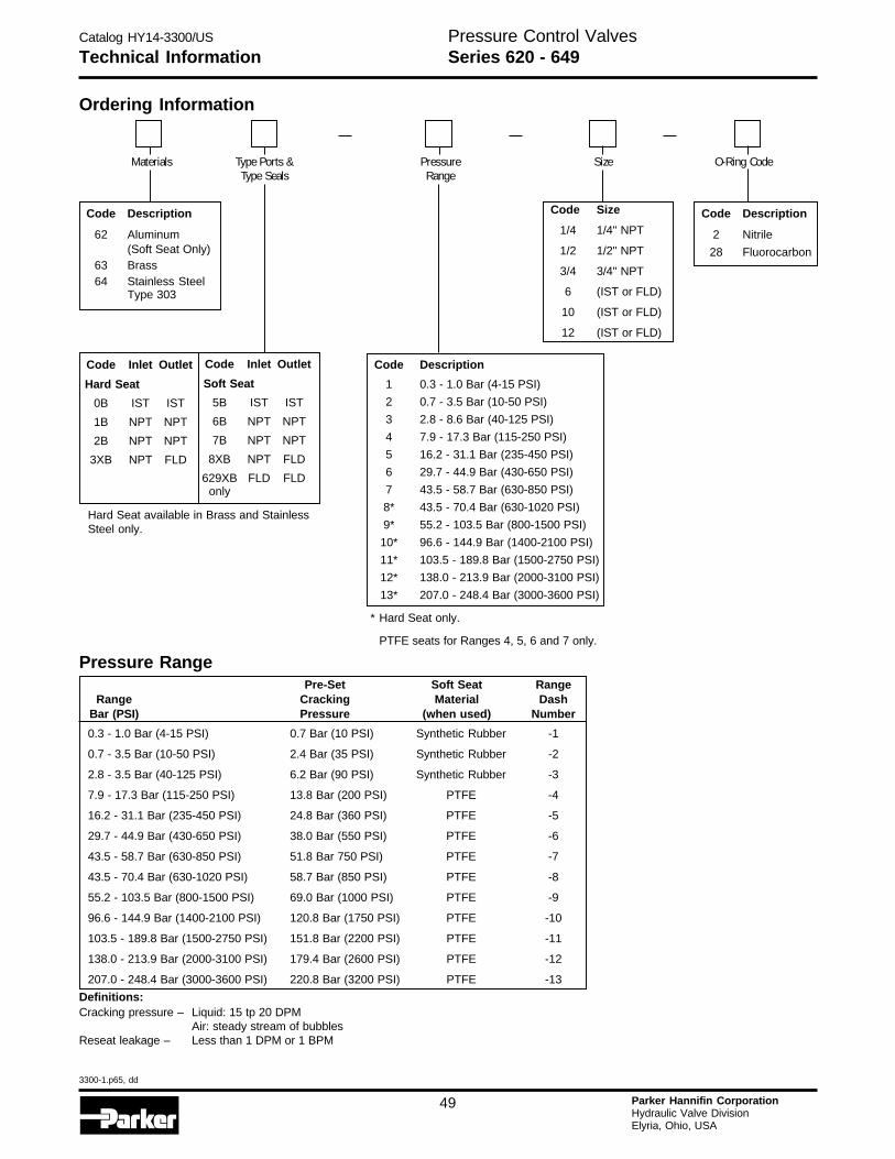
Catalog HY14-3300/US
3300-1.p65, dd
49 Parker Hannifin CorporationHydraulic Valve DivisionElyria, Ohio, USA
Technical InformationPressure Control ValvesSeries 620 - 649
Materials Type Ports &Type Seals
SizePressureRange
O-Ring Code
Hard Seat available in Brass and StainlessSteel only.
Code Description
2 Nitrile
28 Fluorocarbon
Code Size
1/4 1/4" NPT
1/2 1/2" NPT
3/4 3/4" NPT
6 (IST or FLD)
10 (IST or FLD)
12 (IST or FLD)
Code Description
1 0.3 - 1.0 Bar (4-15 PSI)
2 0.7 - 3.5 Bar (10-50 PSI)
3 2.8 - 8.6 Bar (40-125 PSI)
4 7.9 - 17.3 Bar (115-250 PSI)
5 16.2 - 31.1 Bar (235-450 PSI)
6 29.7 - 44.9 Bar (430-650 PSI)
7 43.5 - 58.7 Bar (630-850 PSI)
8* 43.5 - 70.4 Bar (630-1020 PSI)
9* 55.2 - 103.5 Bar (800-1500 PSI)
10* 96.6 - 144.9 Bar (1400-2100 PSI)
11* 103.5 - 189.8 Bar (1500-2750 PSI)
12* 138.0 - 213.9 Bar (2000-3100 PSI)
13* 207.0 - 248.4 Bar (3000-3600 PSI)
Code Inlet Outlet
Hard Seat
0B IST IST
1B NPT NPT
2B NPT NPT
3XB NPT FLD
Code Description
62 Aluminum(Soft Seat Only)
63 Brass64 Stainless Steel
Type 303
Ordering Information
Code Inlet Outlet
Soft Seat
5B IST IST
6B NPT NPT
7B NPT NPT
8XB NPT FLD
629XB FLD FLDonly
Pre-Set Soft Seat RangeRange Cracking Material Dash
Bar (PSI) Pressure (when used) Number
0.3 - 1.0 Bar (4-15 PSI) 0.7 Bar (10 PSI) Synthetic Rubber -1
0.7 - 3.5 Bar (10-50 PSI) 2.4 Bar (35 PSI) Synthetic Rubber -2
2.8 - 3.5 Bar (40-125 PSI) 6.2 Bar (90 PSI) Synthetic Rubber -3
7.9 - 17.3 Bar (115-250 PSI) 13.8 Bar (200 PSI) PTFE -4
16.2 - 31.1 Bar (235-450 PSI) 24.8 Bar (360 PSI) PTFE -5
29.7 - 44.9 Bar (430-650 PSI) 38.0 Bar (550 PSI) PTFE -6
43.5 - 58.7 Bar (630-850 PSI) 51.8 Bar 750 PSI) PTFE -7
43.5 - 70.4 Bar (630-1020 PSI) 58.7 Bar (850 PSI) PTFE -8
55.2 - 103.5 Bar (800-1500 PSI) 69.0 Bar (1000 PSI) PTFE -9
96.6 - 144.9 Bar (1400-2100 PSI) 120.8 Bar (1750 PSI) PTFE -10
103.5 - 189.8 Bar (1500-2750 PSI) 151.8 Bar (2200 PSI) PTFE -11
138.0 - 213.9 Bar (2000-3100 PSI) 179.4 Bar (2600 PSI) PTFE -12
207.0 - 248.4 Bar (3000-3600 PSI) 220.8 Bar (3200 PSI) PTFE -13
Definitions:Cracking pressure – Liquid: 15 tp 20 DPM
Air: steady stream of bubblesReseat leakage – Less than 1 DPM or 1 BPM
* Hard Seat only.
PTFE seats for Ranges 4, 5, 6 and 7 only.
Pressure Range
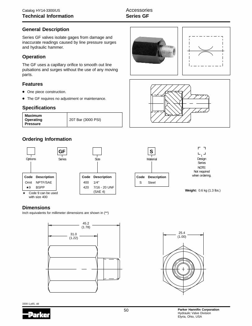
Catalog HY14-3300/US
3300-1.p65, dd
50 Parker Hannifin CorporationHydraulic Valve DivisionElyria, Ohio, USA
H
General Description
Series GF valves isolate gages from damage andinaccurate readings caused by line pressure surgesand hydraulic hammer.
Operation
The GF uses a capillary orifice to smooth out linepulsations and surges without the use of any movingparts.
Features
• One piece construction.
• The GF requires no adjustment or maintenance.
Specifications
Technical Information
MaximumOperating 207 Bar (3000 PSI)Pressure
DimensionsInch equivalents for millimeter dimensions are shown in (**)
Weight: 0.6 kg (1.3 lbs.)
Ordering Information
Size Material
SOptions
Code Description
Omit NPTF/SAE
★9 BSPP
Code Description
400 1/4"
420 7/16 - 20 UNF(SAE 4)
GFSeries
45.2(1.78)
31.0(1.22)
25.4(1.00)
Code Description
S Steel
DesignSeriesNOTE:
Not requiredwhen ordering.
AccessoriesSeries GF
★ Code 9 can be usedwith size 400
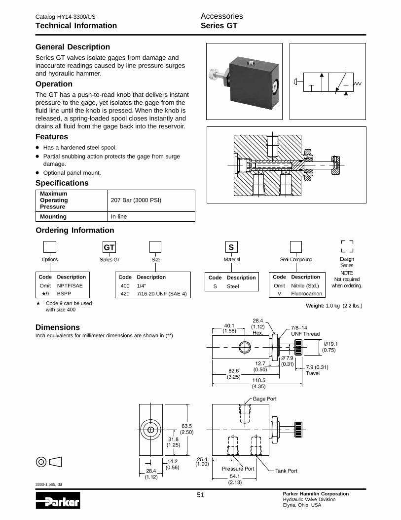
Catalog HY14-3300/US
3300-1.p65, dd
51 Parker Hannifin CorporationHydraulic Valve DivisionElyria, Ohio, USA
Technical Information
MaximumOperating 207 Bar (3000 PSI)Pressure
Mounting In-line
General DescriptionSeries GT valves isolate gages from damage andinaccurate readings caused by line pressure surgesand hydraulic hammer.
OperationThe GT has a push-to-read knob that delivers instantpressure to the gage, yet isolates the gage from thefluid line until the knob is pressed. When the knob isreleased, a spring-loaded spool closes instantly anddrains all fluid from the gage back into the reservoir.
Features• Has a hardened steel spool.
• Partial snubbing action protects the gage from surgedamage.
• Optional panel mount.
Specifications
DimensionsInch equivalents for millimeter dimensions are shown in (**)
Ordering Information
Code Description
400 1/4"
420 7/16-20 UNF (SAE 4)
GTSeries GT Size
Code Description
S Steel
Material
S
Weight: 1.0 kg (2.2 lbs.)
DesignSeriesNOTE:
Not requiredwhen ordering.
Options
Code Description
Omit NPTF/SAE
★9 BSPP
Code Description
Omit Nitrile (Std.)
V Fluorocarbon
Seal Compound
AccessoriesSeries GT
★ Code 9 can be usedwith size 400
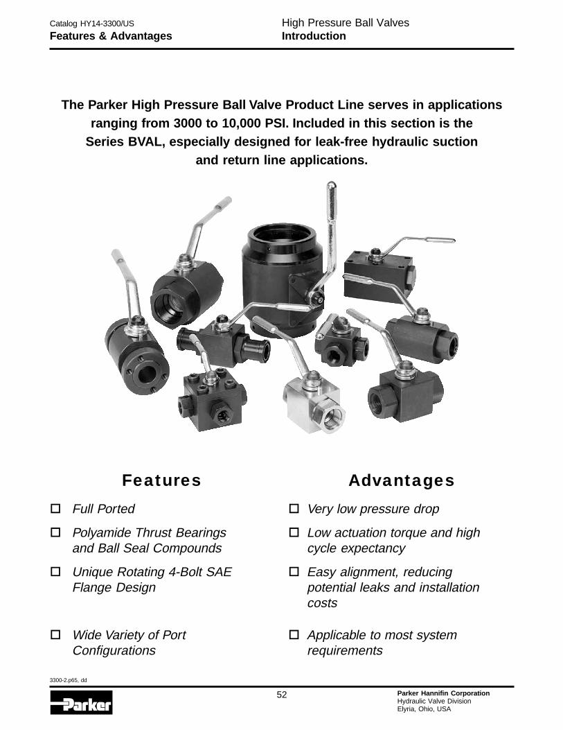
Catalog HY14-3300/US
3300-2.p65, dd
52 Parker Hannifin CorporationHydraulic Valve DivisionElyria, Ohio, USA
H
Features & AdvantagesHigh Pressure Ball ValvesIntroduction
The Parker High Pressure Ball Valve Product Line serves in applicationsranging from 3000 to 10,000 PSI. Included in this section is the
Series BVAL, especially designed for leak-free hydraulic suctionand return line applications.
� Full Ported � Very low pressure drop
� Polyamide Thrust Bearings � Low actuation torque and highand Ball Seal Compounds cycle expectancy
� Unique Rotating 4-Bolt SAE � Easy alignment, reducingFlange Design potential leaks and installation
costs
� Wide Variety of Port � Applicable to most systemConfigurations requirements
Features Advantages
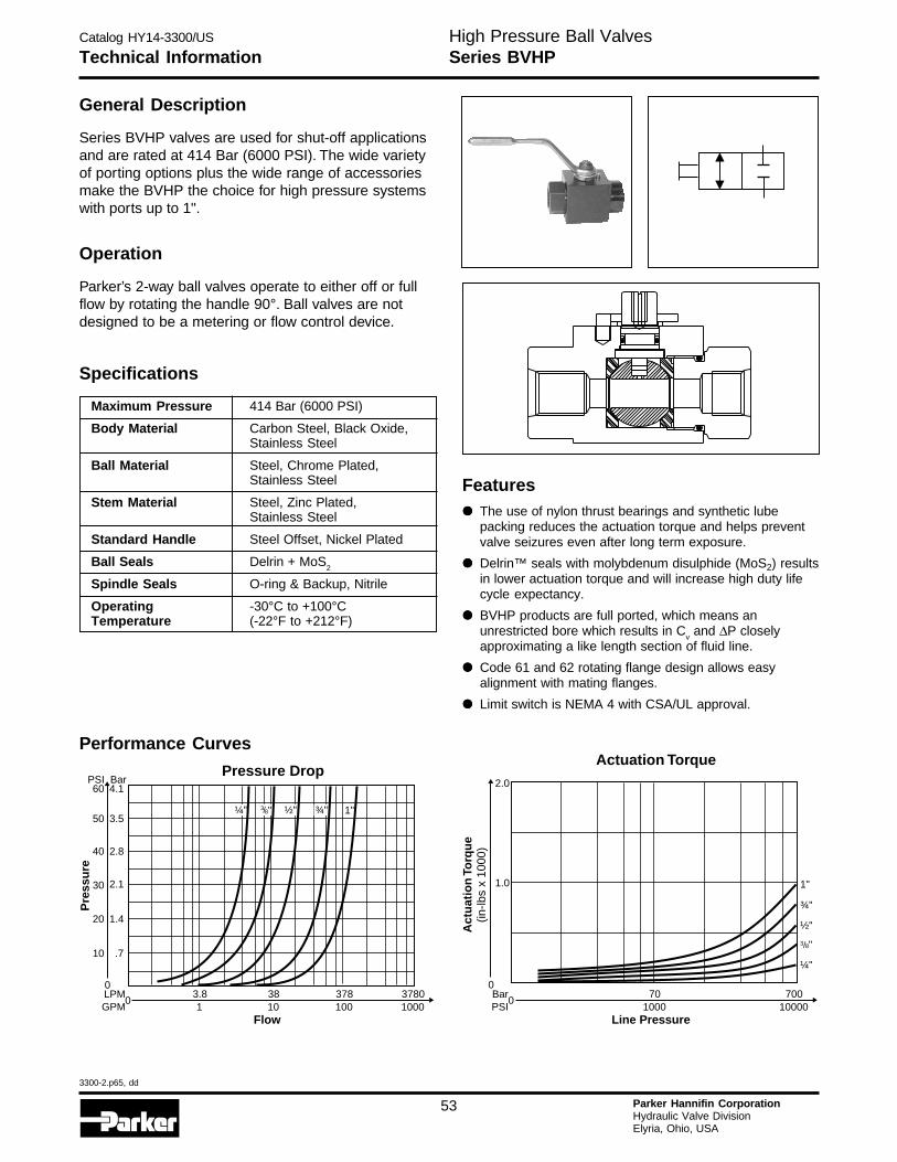
Catalog HY14-3300/US
3300-2.p65, dd
53 Parker Hannifin CorporationHydraulic Valve DivisionElyria, Ohio, USA
Technical InformationHigh Pressure Ball ValvesSeries BVHP
Maximum Pressure 414 Bar (6000 PSI)
Body Material Carbon Steel, Black Oxide,Stainless Steel
Ball Material Steel, Chrome Plated,Stainless Steel
Stem Material Steel, Zinc Plated,Stainless Steel
Standard Handle Steel Offset, Nickel Plated
Ball Seals Delrin + MoS2
Spindle Seals O-ring & Backup, Nitrile
Operating -30°C to +100°CTemperature (-22°F to +212°F)
General Description
Series BVHP valves are used for shut-off applicationsand are rated at 414 Bar (6000 PSI). The wide varietyof porting options plus the wide range of accessoriesmake the BVHP the choice for high pressure systemswith ports up to 1".
Operation
Parker’s 2-way ball valves operate to either off or fullflow by rotating the handle 90°. Ball valves are notdesigned to be a metering or flow control device.
Specifications
Performance Curves
3783.8 381001 10
37801000
Flow
0LPMGPM
Pressure Drop
0
10 .7
20 1.4
30 2.1
40 2.8
50
60PSI
3.5
4.1Bar
Pre
ssu
re
¼" ½" ¾" 1"38/ "
Actuation Torque
1"
701000
70010000
Line Pressure
0
0
1.0
2.0
Act
uat
ion
Torq
ue
(in-lb
s x
1000
)
BarPSI
¾"
½"
3 8/ "
¼"
Features
••••• The use of nylon thrust bearings and synthetic lubepacking reduces the actuation torque and helps preventvalve seizures even after long term exposure.
••••• Delrin™ seals with molybdenum disulphide (MoS2) resultsin lower actuation torque and will increase high duty lifecycle expectancy.
••••• BVHP products are full ported, which means anunrestricted bore which results in Cv and ΔP closelyapproximating a like length section of fluid line.
••••• Code 61 and 62 rotating flange design allows easyalignment with mating flanges.
••••• Limit switch is NEMA 4 with CSA/UL approval.
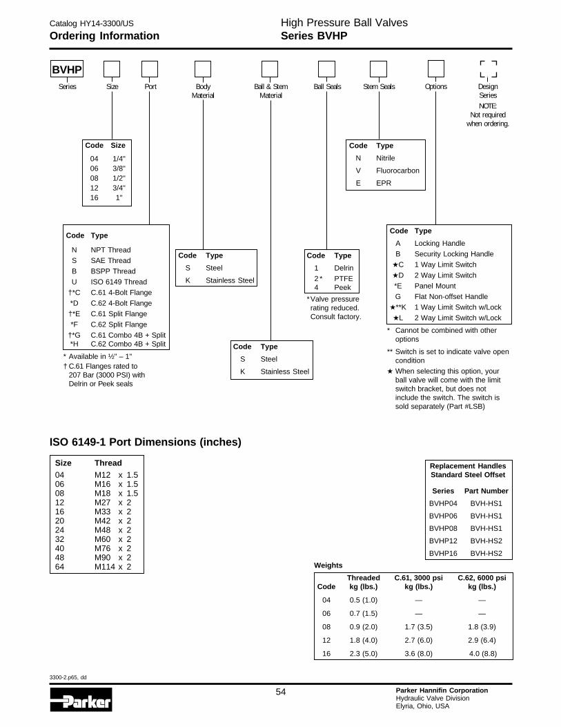
Catalog HY14-3300/US
3300-2.p65, dd
54 Parker Hannifin CorporationHydraulic Valve DivisionElyria, Ohio, USA
H
Ordering InformationHigh Pressure Ball ValvesSeries BVHP
Code Type
1 Delrin
2 * PTFE4 Peek
*Valve pressurerating reduced.Consult factory.
Code Type
N Nitrile
V Fluorocarbon
E EPR
Code Type
N NPT Thread
S SAE Thread
B BSPP Thread
U ISO 6149 Thread
†*C C.61 4-Bolt Flange
*D C.62 4-Bolt Flange
†*E C.61 Split Flange
*F C.62 Split Flange
†*G C.61 Combo 4B + Split*H C.62 Combo 4B + Split
* Available in ½" – 1"† C.61 Flanges rated to
207 Bar (3000 PSI) withDelrin or Peek seals
Code Type
A Locking Handle
B Security Locking Handle
★C 1 Way Limit Switch
★D 2 Way Limit Switch
*E Panel Mount
G Flat Non-offset Handle
★**K 1 Way Limit Switch w/Lock
★L 2 Way Limit Switch w/Lock
* Cannot be combined with otheroptions
** Switch is set to indicate valve opencondition
★ When selecting this option, yourball valve will come with the limitswitch bracket, but does notinclude the switch. The switch issold separately (Part #LSB)
Code Type
S Steel
K Stainless Steel
Code Type
S Steel
K Stainless Steel
Code Size
04 1/4"06 3/8"08 1/2"12 3/4"16 1"
Weights
Threaded C.61, 3000 psi C.62, 6000 psiCode kg (lbs.) kg (lbs.) kg (lbs.)
04 0.5 (1.0) — —
06 0.7 (1.5) — —
08 0.9 (2.0) 1.7 (3.5) 1.8 (3.9)
12 1.8 (4.0) 2.7 (6.0) 2.9 (6.4)
16 2.3 (5.0) 3.6 (8.0) 4.0 (8.8)
BVHPSeries Size Port Body
MaterialBall & Stem
MaterialBall Seals Stem Seals Options Design
SeriesNOTE:
Not requiredwhen ordering.
Replacement HandlesStandard Steel Offset
Series Part Number
BVHP04 BVH-HS1
BVHP06 BVH-HS1
BVHP08 BVH-HS1
BVHP12 BVH-HS2
BVHP16 BVH-HS2
Size Thread04 M12 x 1.506 M16 x 1.508 M18 x 1.512 M27 x 216 M33 x 220 M42 x 224 M48 x 232 M60 x 240 M76 x 248 M90 x 264 M114 x 2
ISO 6149-1 Port Dimensions (inches)
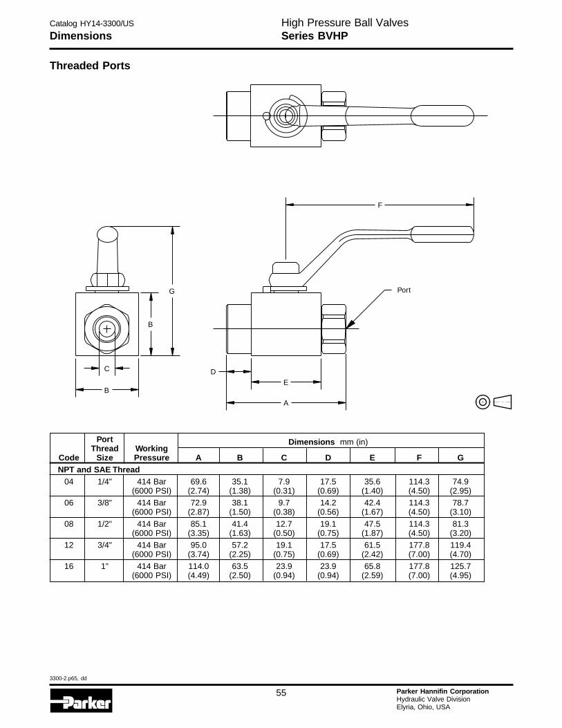
Catalog HY14-3300/US
3300-2.p65, dd
55 Parker Hannifin CorporationHydraulic Valve DivisionElyria, Ohio, USA
DimensionsHigh Pressure Ball ValvesSeries BVHP
Threaded Ports
Port Dimensions mm (in)Thread Working
Code Size Pressure A B C D E F GNPT and SAE Thread
04 1/4" 414 Bar 69.6 35.1 7.9 17.5 35.6 114.3 74.9(6000 PSI) (2.74) (1.38) (0.31) (0.69) (1.40) (4.50) (2.95)
06 3/8" 414 Bar 72.9 38.1 9.7 14.2 42.4 114.3 78.7(6000 PSI) (2.87) (1.50) (0.38) (0.56) (1.67) (4.50) (3.10)
08 1/2" 414 Bar 85.1 41.4 12.7 19.1 47.5 114.3 81.3(6000 PSI) (3.35) (1.63) (0.50) (0.75) (1.87) (4.50) (3.20)
12 3/4" 414 Bar 95.0 57.2 19.1 17.5 61.5 177.8 119.4(6000 PSI) (3.74) (2.25) (0.75) (0.69) (2.42) (7.00) (4.70)
16 1" 414 Bar 114.0 63.5 23.9 23.9 65.8 177.8 125.7(6000 PSI) (4.49) (2.50) (0.94) (0.94) (2.59) (7.00) (4.95)
D
Port
E
A
F
B
C
B
G

Catalog HY14-3300/US
3300-2.p65, dd
56 Parker Hannifin CorporationHydraulic Valve DivisionElyria, Ohio, USA
H
DimensionsHigh Pressure Ball ValvesSeries BVHP
Dimensions mm (in)Flange Working
Code Size Pressure A B C D E F G H J KSAE 4-Bolt C.61 Companion08 1/2" 207 Bar 105.7 41.4 13.0 29.5 47.0 114.3 82.0 17.5 38.1 5/16"-18
(3000 PSI) (4.16) (1.63) (0.51) (1.16) (1.85) (4.50) (3.23) (0.69) (1.50) 5/16"-18
12 3/4" 207 Bar 119.6 57.2 20.1 29.5 61.0 177.8 119.4 22.2 47.6 3/8"-16(3000 PSI) (4.71) (2.25) (0.79) (1.16) (2.40) (7.00) (4.70) (0.88) (1.88) 3/8"-16
16 1" 207 Bar 129.8 63.5 24.9 32.3 65.3 177.8 125.7 26.2 52.6 3/8"-16(3000 PSI) (5.11) (2.50) (0.98) (1.27) (2.57) (7.00) (4.95) (1.03) (2.07) 3/8"-16
SAE 4-Bolt C.62 Companion08 1/2" 414 Bar 105.7 41.4 13.0 29.5 47.0 114.3 82.0 18.3 40.4 5/16"-18
(6000 PSI) (4.16) (1.63) (0.51) (1.16) (1.85) (4.50) (3.23) (0.72) (1.59) 5/16"-18
12 3/4" 414 Bar 119.6 57.2 20.1 29.5 61.0 177.8 119.4 23.9 50.8 3/8"-16(6000 PSI) (4.71) (2.25) (0.79) (1.16) (2.40) (7.00) (4.70) (0.94) (2.00) 3/8"-16
16 1" 414 Bar 129.8 63.5 24.9 32.3 65.3 177.8 125.7 27.8 57.1 7/16"-14(6000 PSI) (5.11) (2.50) (0.98) (1.27) (2.57) (7.00) (4.95) (1.10) (2.25) 7/16"-14
F
E
A
D
G
BJC
KH
B
SAE 4-Bolt Flange
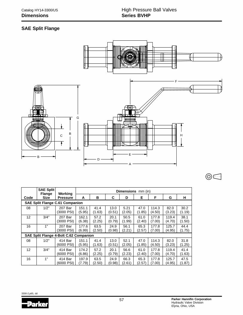
Catalog HY14-3300/US
3300-2.p65, dd
57 Parker Hannifin CorporationHydraulic Valve DivisionElyria, Ohio, USA
DimensionsHigh Pressure Ball ValvesSeries BVHP
SAE Split Flange
SAE Split Dimensions mm (in)Flange Working
Code Size Pressure A B C D E F G HSAE Split Flange C.61 Companion08 1/2" 207 Bar 151.1 41.4 13.0 5.21 47.0 114.3 82.0 30.2
(3000 PSI) (5.95) (1.63) (0.51) (2.05) (1.85) (4.50) (3.23) (1.19)
12 3/4" 207 Bar 162.1 57.2 20.1 50.5 61.0 177.8 119.4 38.1(3000 PSI) (6.38) (2.25) (0.79) (1.99) (2.40) (7.00) (4.70) (1.50)
16 1" 207 Bar 177.6 63.5 24.9 56.1 65.3 177.8 125.7 44.4(3000 PSI) (6.99) (2.50) (0.98) (2.21) (2.57) (7.00) (4.95) (1.75)
SAE Split Flange 4-Bolt C.62 Companion08 1/2" 414 Bar 151.1 41.4 13.0 52.1 47.0 114.3 82.0 31.8
(6000 PSI) (5.95) (1.63) (0.51) (2.05) (1.85) (4.50) (3.23) (1.25)
12 3/4" 414 Bar 174.2 57.2 20.1 56.6 61.0 177.8 119.4 41.4(6000 PSI) (6.86) (2.25) (0.79) (2.23) (2.40) (7.00) (4.70) (1.63)
16 1" 414 Bar 197.9 63.5 24.9 66.3 65.3 177.8 125.7 47.5(6000 PSI) (7.79) (2.50) (0.98) (2.61) (2.57) (7.00) (4.95) (1.87)
F
H
E
A
D
G
BC
B
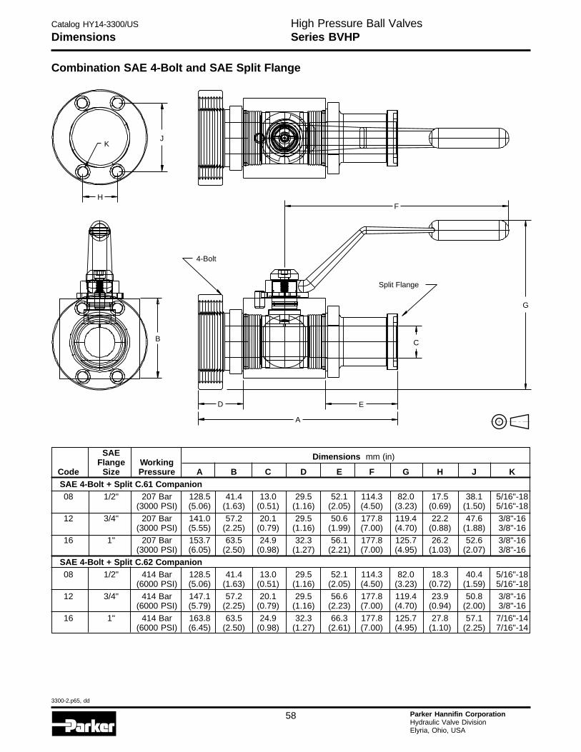
Catalog HY14-3300/US
3300-2.p65, dd
58 Parker Hannifin CorporationHydraulic Valve DivisionElyria, Ohio, USA
H
DimensionsHigh Pressure Ball ValvesSeries BVHP
SAE Dimensions mm (in)Flange Working
Code Size Pressure A B C D E F G H J KSAE 4-Bolt + Split C.61 Companion08 1/2" 207 Bar 128.5 41.4 13.0 29.5 52.1 114.3 82.0 17.5 38.1 5/16"-18
(3000 PSI) (5.06) (1.63) (0.51) (1.16) (2.05) (4.50) (3.23) (0.69) (1.50) 5/16"-18
12 3/4" 207 Bar 141.0 57.2 20.1 29.5 50.6 177.8 119.4 22.2 47.6 3/8"-16(3000 PSI) (5.55) (2.25) (0.79) (1.16) (1.99) (7.00) (4.70) (0.88) (1.88) 3/8"-16
16 1" 207 Bar 153.7 63.5 24.9 32.3 56.1 177.8 125.7 26.2 52.6 3/8"-16(3000 PSI) (6.05) (2.50) (0.98) (1.27) (2.21) (7.00) (4.95) (1.03) (2.07) 3/8"-16
SAE 4-Bolt + Split C.62 Companion08 1/2" 414 Bar 128.5 41.4 13.0 29.5 52.1 114.3 82.0 18.3 40.4 5/16"-18
(6000 PSI) (5.06) (1.63) (0.51) (1.16) (2.05) (4.50) (3.23) (0.72) (1.59) 5/16"-18
12 3/4" 414 Bar 147.1 57.2 20.1 29.5 56.6 177.8 119.4 23.9 50.8 3/8"-16(6000 PSI) (5.79) (2.25) (0.79) (1.16) (2.23) (7.00) (4.70) (0.94) (2.00) 3/8"-16
16 1" 414 Bar 163.8 63.5 24.9 32.3 66.3 177.8 125.7 27.8 57.1 7/16"-14(6000 PSI) (6.45) (2.50) (0.98) (1.27) (2.61) (7.00) (4.95) (1.10) (2.25) 7/16"-14
Combination SAE 4-Bolt and SAE Split Flange
F
G
C
Split Flange
E
A
D
B
4-Bolt
KJ
H
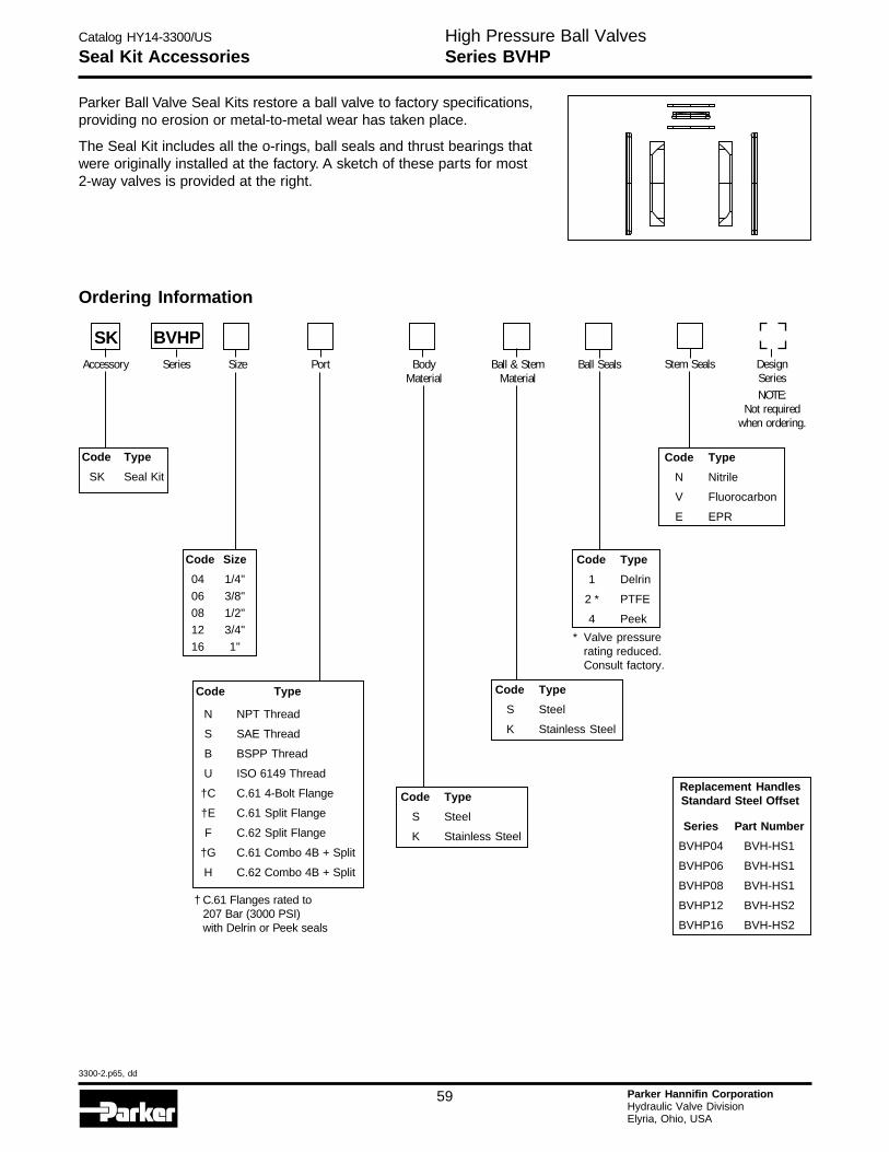
Catalog HY14-3300/US
3300-2.p65, dd
59 Parker Hannifin CorporationHydraulic Valve DivisionElyria, Ohio, USA
Seal Kit AccessoriesHigh Pressure Ball ValvesSeries BVHP
Code Type
N Nitrile
V Fluorocarbon
E EPR
Parker Ball Valve Seal Kits restore a ball valve to factory specifications,providing no erosion or metal-to-metal wear has taken place.
The Seal Kit includes all the o-rings, ball seals and thrust bearings thatwere originally installed at the factory. A sketch of these parts for most2-way valves is provided at the right.
Ordering Information
Code Type
SK Seal Kit
Code Type
S Steel
K Stainless Steel
Code Type
N NPT Thread
S SAE Thread
B BSPP Thread
U ISO 6149 Thread
†C C.61 4-Bolt Flange
†E C.61 Split Flange
F C.62 Split Flange
†G C.61 Combo 4B + Split
H C.62 Combo 4B + Split
Code Type
1 Delrin
2 * PTFE
4 Peek
Code Type
S Steel
K Stainless Steel
Code Size
04 1/4"
06 3/8"
08 1/2"
12 3/4"
16 1"
SK BVHPAccessory Series Size Port Body
MaterialBall & Stem
MaterialBall Seals Stem Seals Design
SeriesNOTE:
Not requiredwhen ordering.
Replacement HandlesStandard Steel Offset
Series Part Number
BVHP04 BVH-HS1
BVHP06 BVH-HS1
BVHP08 BVH-HS1
BVHP12 BVH-HS2
BVHP16 BVH-HS2
* Valve pressurerating reduced.Consult factory.
† C.61 Flanges rated to207 Bar (3000 PSI)with Delrin or Peek seals
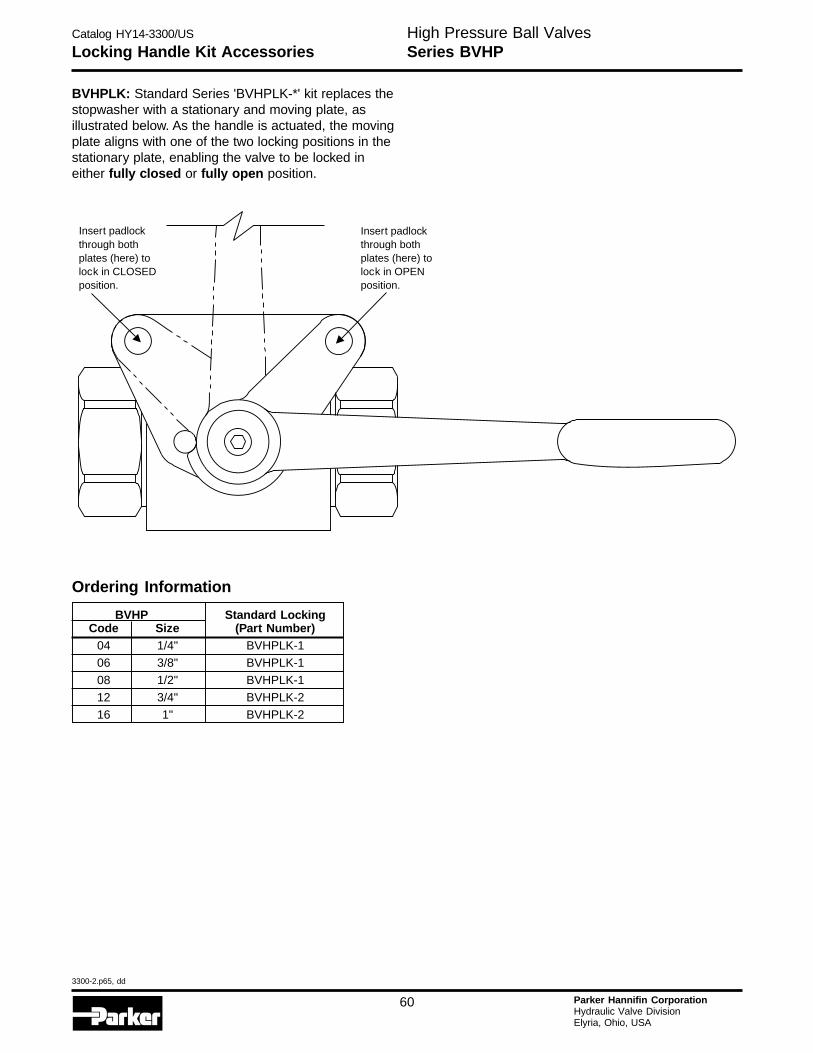
Catalog HY14-3300/US
3300-2.p65, dd
60 Parker Hannifin CorporationHydraulic Valve DivisionElyria, Ohio, USA
H
Locking Handle Kit AccessoriesHigh Pressure Ball ValvesSeries BVHP
BVHPLK: Standard Series 'BVHPLK-*' kit replaces thestopwasher with a stationary and moving plate, asillustrated below. As the handle is actuated, the movingplate aligns with one of the two locking positions in thestationary plate, enabling the valve to be locked ineither fully closed or fully open position.
Ordering Information
BVHP Standard LockingCode Size (Part Number)
04 1/4" BVHPLK-106 3/8" BVHPLK-1
08 1/2" BVHPLK-1
12 3/4" BVHPLK-216 1" BVHPLK-2
through bothplates (here) tolock in CLOSEDposition.
Insert padlockInsert padlockthrough bothplates (here) tolock in OPENposition.
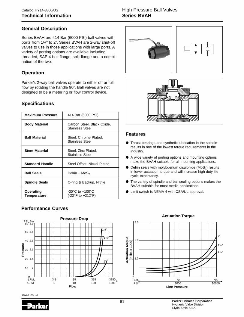
Catalog HY14-3300/US
3300-2.p65, dd
61 Parker Hannifin CorporationHydraulic Valve DivisionElyria, Ohio, USA
Technical InformationHigh Pressure Ball ValvesSeries BVAH
General Description
Series BVAH are 414 Bar (6000 PSI) ball valves withports from 1¼" to 2". Series BVAH are 2-way shut-offvalves to use in those applications with large ports. Avariety of porting options are available includingthreaded, SAE 4-bolt flange, split flange and a combi-nation of the two.
Operation
Parker’s 2-way ball valves operate to either off or fullflow by rotating the handle 90°. Ball valves are notdesigned to be a metering or flow control device.
Specifications
Maximum Pressure 414 Bar (6000 PSI)
Body Material Carbon Steel, Black Oxide,Stainless Steel
Ball Material Steel, Chrome Plated,Stainless Steel
Stem Material Steel, Zinc Plated,Stainless Steel
Standard Handle Steel Offset, Nickel Plated
Ball Seals Delrin + MoS2
Spindle Seals O-ring & Backup, Nitrile
Operating -30°C to +100°CTemperature (-22°F to +212°F)
Performance Curves
3783.8 381001 10
37801000
Flow
0LPMGPM
Pressure Drop
0
10 .7
20 1.4
30 2.1
40 2.8
50
60PSI
3.5
4.1Bar
Pre
ssu
re
1¼"
1½"
2"
Actuation Torque
1¼"
1½"
2"
701000
70010000
Line Pressure
0
0
2.0
1.0
3.0
Act
uat
ion
Torq
ue
(in-lb
s x
1000
)
BarPSI
Features
••••• Thrust bearings and synthetic lubrication in the spindleresults in one of the lowest torque requirements in theindustry.
••••• A wide variety of porting options and mounting optionsmake the BVAH suitable for all mounting applications.
••••• Delrin seals with molybdenum disulphide (MoS2) resultsin lower actuation torque and will increase high duty lifecycle expectancy.
••••• The variety of spindle and ball sealing options makes theBVAH suitable for most media applications.
••••• Limit switch is NEMA 4 with CSA/UL approval.
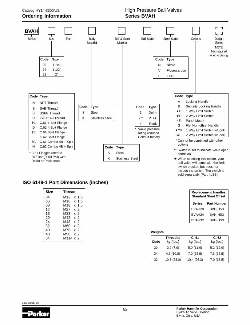
Catalog HY14-3300/US
3300-2.p65, dd
62 Parker Hannifin CorporationHydraulic Valve DivisionElyria, Ohio, USA
H
Ordering InformationHigh Pressure Ball ValvesSeries BVAH
Weights
Threaded C. 61 C. 62 Code kg (lbs.) kg (lbs.) kg (lbs.)
20 3.2 (7.0) 5.0 (11.0) 5.2 (12.9)
24 4.5 (10.0) 7.0 (15.5) 7.3 (16.5)
32 10.5 (23.0) 10.4 (26.2) 7.0 (15.5)
Code Type
N NPT Thread
S SAE Thread
B BSPP Thread
U ISO 6149 Thread
†C C.61 4-Bolt Flange
D C.62 4-Bolt Flange
†E C.61 Split Flange
F C.62 Split Flange
†G C.61 Combo 4B + Split
H C.62 Combo 4B + Split
Code Type
A Locking Handle
B Security Locking Handle
★C 1 Way Limit Switch
★D 2 Way Limit Switch
*E Panel Mount
G Flat Non-offset Handle
★**K 1 Way Limit Switch w/Lock
★L 2 Way Limit Switch w/Lock
* Cannot be combined with otheroptions
** Switch is set to indicate valve opencondition
★ When selecting this option, yourball valve will come with the limitswitch bracket, but does notinclude the switch. The switch issold separately (Part #LSB)
Code Type
1 Delrin
2 * PTFE
4 Peek
Code Type
S Steel
K Stainless Steel
Code Type
N Nitrile
V Fluorocarbon
E EPR
Code Type
S Steel
K Stainless Steel
Code Size
20 1 1/4"
24 1 1/2"
32 2"
BVAHSeries Size Port Body
MaterialBall & Stem
MaterialBall Seals Stem Seals Options Design
SeriesNOTE:
Not requiredwhen ordering.
Replacement HandlesStandard Steel Offset
Series Part Number
BVAH20 BVH-HS3
BVAH24 BVH-HS3
BVAH32 BVH-HS3
* Valve pressurerating reduced.Consult factory.
ISO 6149-1 Port Dimensions (inches)
Size Thread04 M12 x 1.506 M16 x 1.508 M18 x 1.512 M27 x 216 M33 x 220 M42 x 224 M48 x 232 M60 x 240 M76 x 248 M90 x 264 M114 x 2
† C.61 Flanges rated to207 Bar (3000 PSI) withDelrin or Peek seals
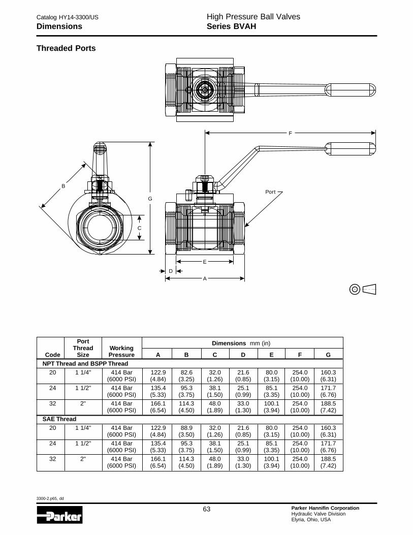
Catalog HY14-3300/US
3300-2.p65, dd
63 Parker Hannifin CorporationHydraulic Valve DivisionElyria, Ohio, USA
DimensionsHigh Pressure Ball ValvesSeries BVAH
Threaded Ports
Port Dimensions mm (in)Thread Working
Code Size Pressure A B C D E F GNPT Thread and BSPP Thread
20 1 1/4" 414 Bar 122.9 82.6 32.0 21.6 80.0 254.0 160.3(6000 PSI) (4.84) (3.25) (1.26) (0.85) (3.15) (10.00) (6.31)
24 1 1/2" 414 Bar 135.4 95.3 38.1 25.1 85.1 254.0 171.7(6000 PSI) (5.33) (3.75) (1.50) (0.99) (3.35) (10.00) (6.76)
32 2" 414 Bar 166.1 114.3 48.0 33.0 100.1 254.0 188.5(6000 PSI) (6.54) (4.50) (1.89) (1.30) (3.94) (10.00) (7.42)
SAE Thread20 1 1/4" 414 Bar 122.9 88.9 32.0 21.6 80.0 254.0 160.3
(6000 PSI) (4.84) (3.50) (1.26) (0.85) (3.15) (10.00) (6.31)
24 1 1/2" 414 Bar 135.4 95.3 38.1 25.1 85.1 254.0 171.7(6000 PSI) (5.33) (3.75) (1.50) (0.99) (3.35) (10.00) (6.76)
32 2" 414 Bar 166.1 114.3 48.0 33.0 100.1 254.0 188.5(6000 PSI) (6.54) (4.50) (1.89) (1.30) (3.94) (10.00) (7.42)
B
G
C
F
Port
D
E
A
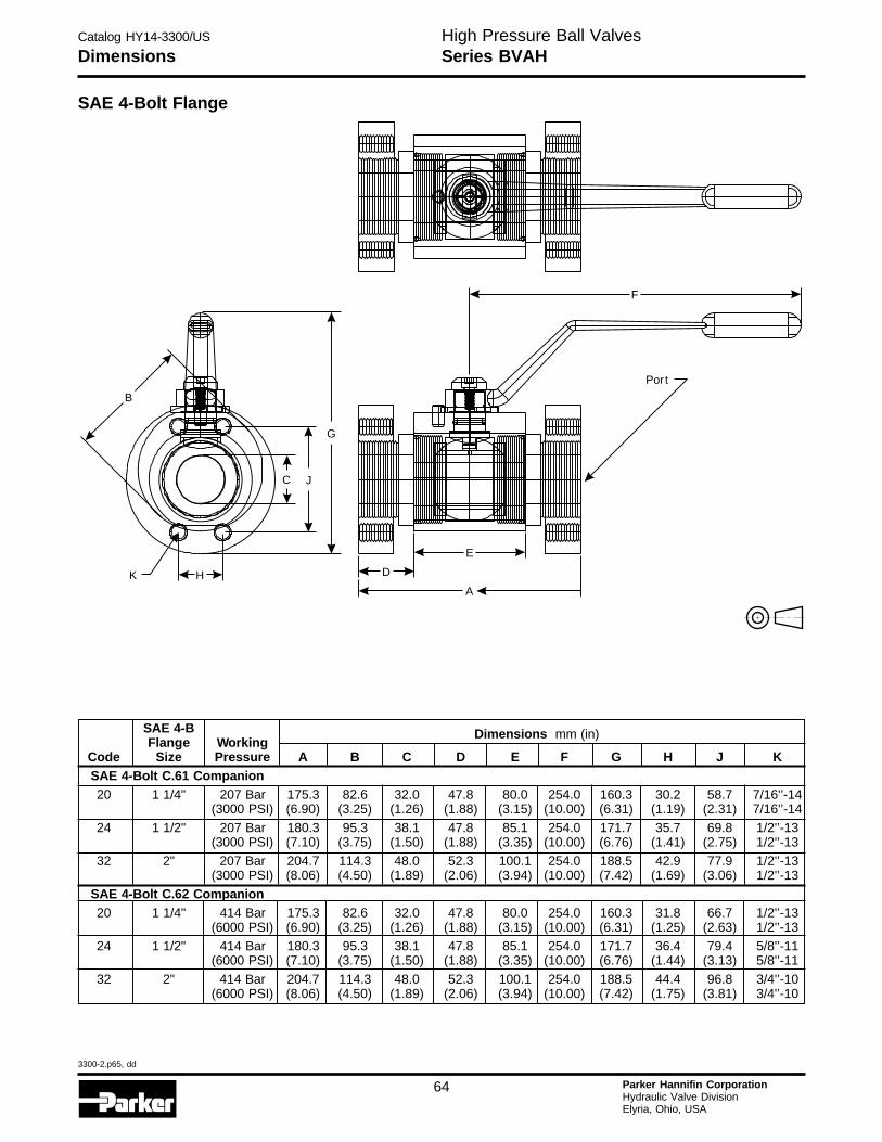
Catalog HY14-3300/US
3300-2.p65, dd
64 Parker Hannifin CorporationHydraulic Valve DivisionElyria, Ohio, USA
H
DimensionsHigh Pressure Ball ValvesSeries BVAH
SAE 4-Bolt Flange
SAE 4-B Dimensions mm (in)Flange Working
Code Size Pressure A B C D E F G H J KSAE 4-Bolt C.61 Companion20 1 1/4" 207 Bar 175.3 82.6 32.0 47.8 80.0 254.0 160.3 30.2 58.7 7/16'’-14
(3000 PSI) (6.90) (3.25) (1.26) (1.88) (3.15) (10.00) (6.31) (1.19) (2.31) 7/16'’-14
24 1 1/2" 207 Bar 180.3 95.3 38.1 47.8 85.1 254.0 171.7 35.7 69.8 1/2'’-13(3000 PSI) (7.10) (3.75) (1.50) (1.88) (3.35) (10.00) (6.76) (1.41) (2.75) 1/2'’-13
32 2" 207 Bar 204.7 114.3 48.0 52.3 100.1 254.0 188.5 42.9 77.9 1/2'’-13(3000 PSI) (8.06) (4.50) (1.89) (2.06) (3.94) (10.00) (7.42) (1.69) (3.06) 1/2'’-13
SAE 4-Bolt C.62 Companion20 1 1/4" 414 Bar 175.3 82.6 32.0 47.8 80.0 254.0 160.3 31.8 66.7 1/2'’-13
(6000 PSI) (6.90) (3.25) (1.26) (1.88) (3.15) (10.00) (6.31) (1.25) (2.63) 1/2'’-1324 1 1/2" 414 Bar 180.3 95.3 38.1 47.8 85.1 254.0 171.7 36.4 79.4 5/8'’-11
(6000 PSI) (7.10) (3.75) (1.50) (1.88) (3.35) (10.00) (6.76) (1.44) (3.13) 5/8'’-11
32 2" 414 Bar 204.7 114.3 48.0 52.3 100.1 254.0 188.5 44.4 96.8 3/4'’-10(6000 PSI) (8.06) (4.50) (1.89) (2.06) (3.94) (10.00) (7.42) (1.75) (3.81) 3/4'’-10
F
Por t
D
E
A
B
K H
C J
G
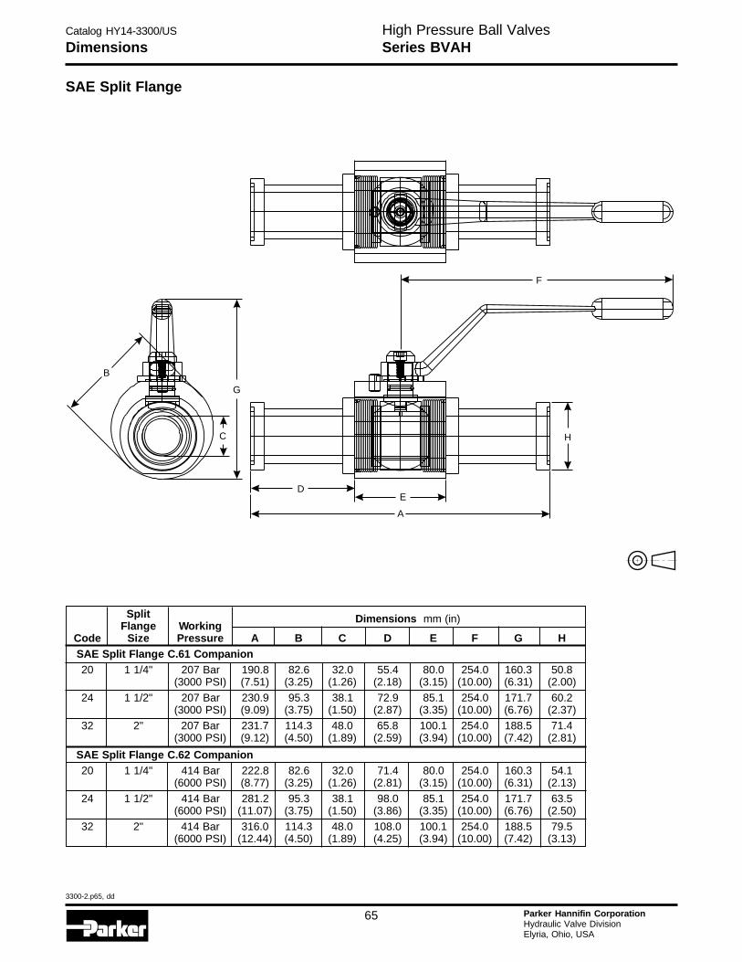
Catalog HY14-3300/US
3300-2.p65, dd
65 Parker Hannifin CorporationHydraulic Valve DivisionElyria, Ohio, USA
High Pressure Ball ValvesSeries BVAHDimensions
SAE Split Flange
Split Dimensions mm (in)Flange Working
Code Size Pressure A B C D E F G HSAE Split Flange C.61 Companion20 1 1/4" 207 Bar 190.8 82.6 32.0 55.4 80.0 254.0 160.3 50.8
(3000 PSI) (7.51) (3.25) (1.26) (2.18) (3.15) (10.00) (6.31) (2.00)
24 1 1/2" 207 Bar 230.9 95.3 38.1 72.9 85.1 254.0 171.7 60.2(3000 PSI) (9.09) (3.75) (1.50) (2.87) (3.35) (10.00) (6.76) (2.37)
32 2" 207 Bar 231.7 114.3 48.0 65.8 100.1 254.0 188.5 71.4(3000 PSI) (9.12) (4.50) (1.89) (2.59) (3.94) (10.00) (7.42) (2.81)
SAE Split Flange C.62 Companion20 1 1/4" 414 Bar 222.8 82.6 32.0 71.4 80.0 254.0 160.3 54.1
(6000 PSI) (8.77) (3.25) (1.26) (2.81) (3.15) (10.00) (6.31) (2.13)
24 1 1/2" 414 Bar 281.2 95.3 38.1 98.0 85.1 254.0 171.7 63.5(6000 PSI) (11.07) (3.75) (1.50) (3.86) (3.35) (10.00) (6.76) (2.50)
32 2" 414 Bar 316.0 114.3 48.0 108.0 100.1 254.0 188.5 79.5(6000 PSI) (12.44) (4.50) (1.89) (4.25) (3.94) (10.00) (7.42) (3.13)
F
DE
A
H
B
G
C
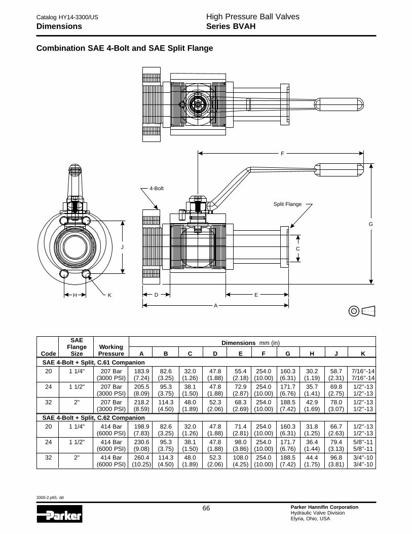
Catalog HY14-3300/US
3300-2.p65, dd
66 Parker Hannifin CorporationHydraulic Valve DivisionElyria, Ohio, USA
H
DimensionsHigh Pressure Ball ValvesSeries BVAH
Combination SAE 4-Bolt and SAE Split Flange
SAE Dimensions mm (in)Flange Working
Code Size Pressure A B C D E F G H J KSAE 4-Bolt + Split, C.61 Companion20 1 1/4" 207 Bar 183.9 82.6 32.0 47.8 55.4 254.0 160.3 30.2 58.7 7/16'’-14
(3000 PSI) (7.24) (3.25) (1.26) (1.88) (2.18) (10.00) (6.31) (1.19) (2.31) 7/16'’-14
24 1 1/2" 207 Bar 205.5 95.3 38.1 47.8 72.9 254.0 171.7 35.7 69.8 1/2'’-13(3000 PSI) (8.09) (3.75) (1.50) (1.88) (2.87) (10.00) (6.76) (1.41) (2.75) 1/2'’-13
32 2" 207 Bar 218.2 114.3 48.0 52.3 68.3 254.0 188.5 42.9 78.0 1/2'’-13(3000 PSI) (8.59) (4.50) (1.89) (2.06) (2.69) (10.00) (7.42) (1.69) (3.07) 1/2'’-13
SAE 4-Bolt + Split, C.62 Companion20 1 1/4" 414 Bar 198.9 82.6 32.0 47.8 71.4 254.0 160.3 31.8 66.7 1/2'’-13
(6000 PSI) (7.83) (3.25) (1.26) (1.88) (2.81) (10.00) (6.31) (1.25) (2.63) 1/2'’-1324 1 1/2" 414 Bar 230.6 95.3 38.1 47.8 98.0 254.0 171.7 36.4 79.4 5/8'’-11
(6000 PSI) (9.08) (3.75) (1.50) (1.88) (3.86) (10.00) (6.76) (1.44) (3.13) 5/8'’-11
32 2" 414 Bar 260.4 114.3 48.0 52.3 108.0 254.0 188.5 44.4 96.8 3/4'’-10(6000 PSI) (10.25) (4.50) (1.89) (2.06) (4.25) (10.00) (7.42) (1.75) (3.81) 3/4'’-10
H K
J
F
4-Bolt
Split Flange
D
A
E
G
C
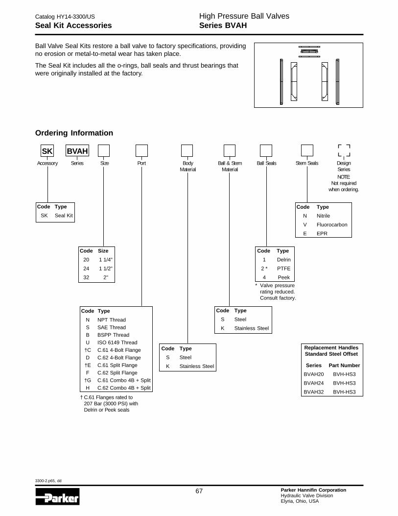
Catalog HY14-3300/US
3300-2.p65, dd
67 Parker Hannifin CorporationHydraulic Valve DivisionElyria, Ohio, USA
Seal Kit AccessoriesHigh Pressure Ball ValvesSeries BVAH
Ball Valve Seal Kits restore a ball valve to factory specifications, providingno erosion or metal-to-metal wear has taken place.
The Seal Kit includes all the o-rings, ball seals and thrust bearings thatwere originally installed at the factory.
Ordering Information
Code Type
SK Seal Kit
Code Type
S Steel
K Stainless Steel
Code Type
N Nitrile
V Fluorocarbon
E EPR
Code Type
1 Delrin
2 * PTFE
4 Peek
Code Type
S Steel
K Stainless Steel
Code Type
N NPT Thread
S SAE Thread
B BSPP Thread
U ISO 6149 Thread
†C C.61 4-Bolt Flange
D C.62 4-Bolt Flange
†E C.61 Split Flange
F C.62 Split Flange
†G C.61 Combo 4B + Split
H C.62 Combo 4B + Split
Code Size
20 1 1/4"
24 1 1/2"
32 2"
SK BVAHAccessory Series Size Port Body
MaterialBall & Stem
MaterialBall Seals Stem Seals Design
SeriesNOTE:
Not requiredwhen ordering.
Replacement HandlesStandard Steel Offset
Series Part Number
BVAH20 BVH-HS3
BVAH24 BVH-HS3
BVAH32 BVH-HS3
* Valve pressurerating reduced.Consult factory.
† C.61 Flanges rated to207 Bar (3000 PSI) withDelrin or Peek seals
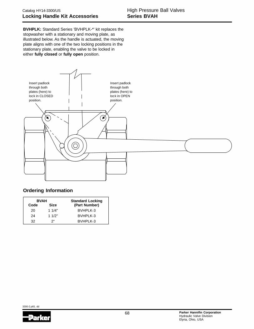
Catalog HY14-3300/US
3300-2.p65, dd
68 Parker Hannifin CorporationHydraulic Valve DivisionElyria, Ohio, USA
H
Locking Handle Kit AccessoriesHigh Pressure Ball ValvesSeries BVAH
BVHPLK: Standard Series 'BVHPLK-*' kit replaces thestopwasher with a stationary and moving plate, asillustrated below. As the handle is actuated, the movingplate aligns with one of the two locking positions in thestationary plate, enabling the valve to be locked ineither fully closed or fully open position.
Ordering Information
BVAH Standard LockingCode Size (Part Number)
20 1 1/4" BVHPLK-324 1 1/2" BVHPLK-3
32 2" BVHPLK-3
Insert padlockthrough bothplates (here) tolock in CLOSEDposition.
Insert padlockthrough bothplates (here) tolock in OPENposition.
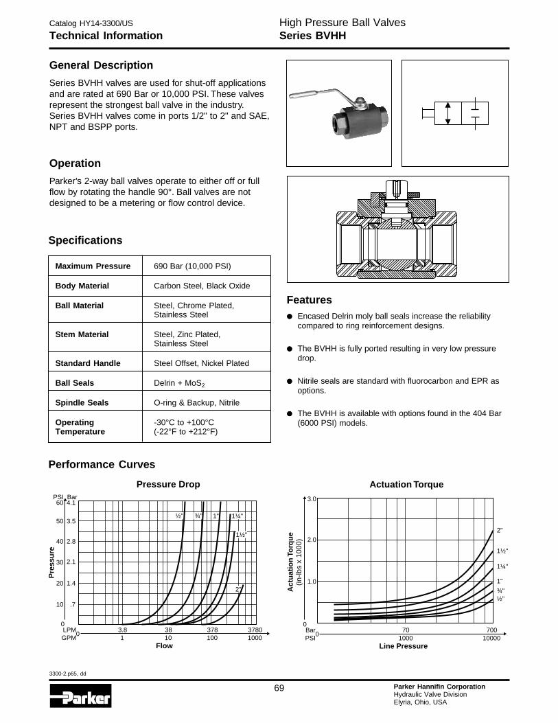
Catalog HY14-3300/US
3300-2.p65, dd
69 Parker Hannifin CorporationHydraulic Valve DivisionElyria, Ohio, USA
Technical InformationHigh Pressure Ball ValvesSeries BVHH
General Description
Series BVHH valves are used for shut-off applicationsand are rated at 690 Bar or 10,000 PSI. These valvesrepresent the strongest ball valve in the industry.Series BVHH valves come in ports 1/2" to 2" and SAE,NPT and BSPP ports.
Operation
Parker’s 2-way ball valves operate to either off or fullflow by rotating the handle 90°. Ball valves are notdesigned to be a metering or flow control device.
Specifications
Maximum Pressure 690 Bar (10,000 PSI)
Body Material Carbon Steel, Black Oxide
Ball Material Steel, Chrome Plated,Stainless Steel
Stem Material Steel, Zinc Plated,Stainless Steel
Standard Handle Steel Offset, Nickel Plated
Ball Seals Delrin + MoS2
Spindle Seals O-ring & Backup, Nitrile
Operating -30°C to +100°CTemperature (-22°F to +212°F)
Performance Curves
3783.8 381001 10
37801000
Flow
0LPMGPM
Pressure Drop
0
10 .7
20 1.4
30 2.1
40 2.8
50
60PSI
3.5
4.1Bar
Pre
ssu
re
½" ¾" 1" 1¼"
1½"
2"
Actuation Torque
1¼"
1½"
2"
1"
701000
70010000
Line Pressure
0
0
2.0
1.0
3.0
Act
uat
ion
Torq
ue
(in-lb
s x
1000
)
BarPSI
¾"½"
Features
••••• Encased Delrin moly ball seals increase the reliabilitycompared to ring reinforcement designs.
••••• The BVHH is fully ported resulting in very low pressuredrop.
••••• Nitrile seals are standard with fluorocarbon and EPR asoptions.
••••• The BVHH is available with options found in the 404 Bar(6000 PSI) models.
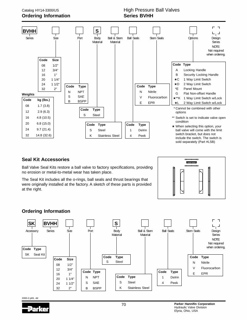
Catalog HY14-3300/US
3300-2.p65, dd
70 Parker Hannifin CorporationHydraulic Valve DivisionElyria, Ohio, USA
H
Ordering InformationHigh Pressure Ball ValvesSeries BVHH
Seal Kit Accessories
Ball Valve Seal Kits restore a ball valve to factory specifications, providingno erosion or metal-to-metal wear has taken place.
The Seal Kit includes all the o-rings, ball seals and thrust bearings thatwere originally installed at the factory. A sketch of these parts is providedat the right.
Ordering Information
Code Type
SK Seal Kit
Code Type
N NPT
S SAE
B BSPP
Code Type
1 Delrin
4 Peek
Code Type
N Nitrile
V Fluorocarbon
E EPRCode Type
S Steel
K Stainless Steel
Code Size
08 1/2"
12 3/4"
16 1"
20 1 1/4"
24 1 1/2"
32 2"
Code TypeS Steel
SKAccessory Series Size Port Body
MaterialBall & Stem
MaterialBall Seals Stem Seals Design
SeriesNOTE:
Not requiredwhen ordering.
S
Code Type
N NPT
S SAE
B BSPP
Code Type
1 Delrin
4 Peek
Code Type
S Steel
Code Type
N Nitrile
V Fluorocarbon
E EPR
Code Type
S Steel
K Stainless Steel
Code Size
08 1/2"
12 3/4"
16 1"
20 1 1/4"
24 1 1/2"
32 2"
Weights
Code kg (lbs.)
08 1.7 (3.8)
12 2.9 (6.3)
16 4.8 (10.5)
20 6.8 (15.0)
24 9.7 (21.4)
32 14.8 (32.6)
BVHHSeries Size Port Body
MaterialBall & Stem
MaterialBall Seals Stem Seals Options Design
SeriesNOTE:
Not requiredwhen ordering.
S
BVHH
Code Type
A Locking Handle
B Security Locking Handle
★C 1 Way Limit Switch
★D 2 Way Limit Switch
*E Panel Mount
G Flat Non-offset Handle
★**K 1 Way Limit Switch w/Lock
★L 2 Way Limit Switch w/Lock
* Cannot be combined with otheroptions
** Switch is set to indicate valve opencondition
★ When selecting this option, yourball valve will come with the limitswitch bracket, but does notinclude the switch. The switch issold separately (Part #LSB)
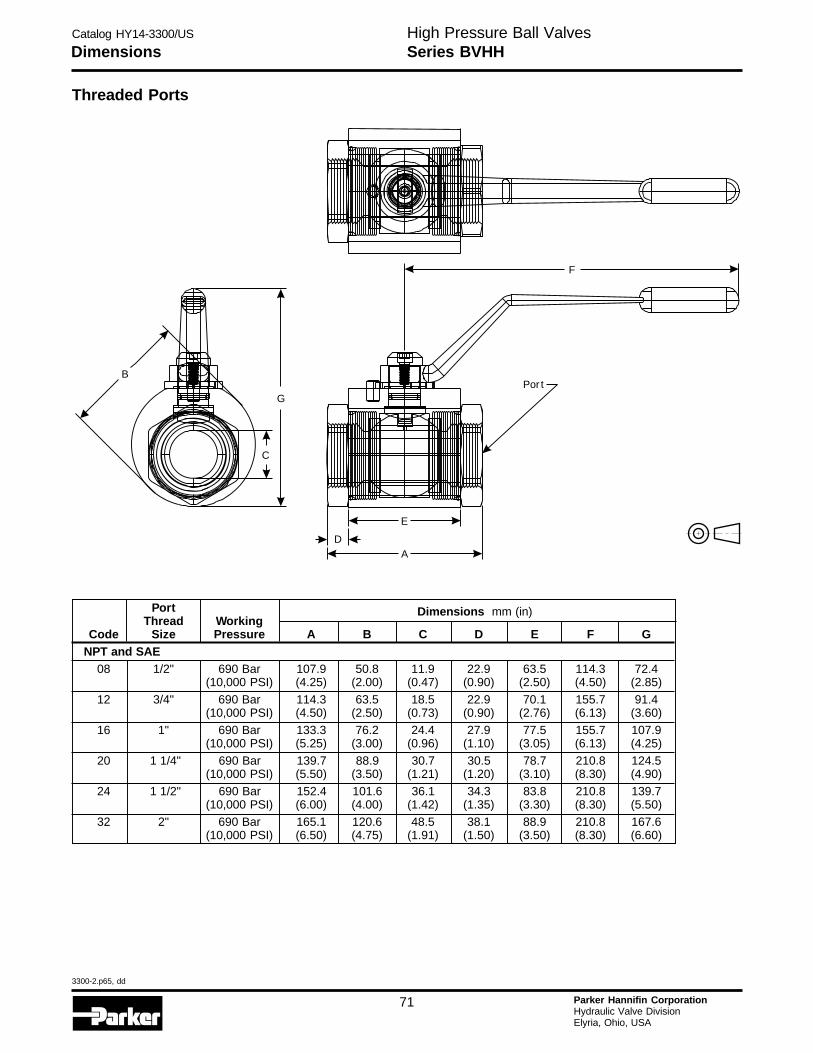
Catalog HY14-3300/US
3300-2.p65, dd
71 Parker Hannifin CorporationHydraulic Valve DivisionElyria, Ohio, USA
DimensionsHigh Pressure Ball ValvesSeries BVHH
Threaded Ports
Port Dimensions mm (in)Thread Working
Code Size Pressure A B C D E F GNPT and SAE
08 1/2" 690 Bar 107.9 50.8 11.9 22.9 63.5 114.3 72.4(10,000 PSI) (4.25) (2.00) (0.47) (0.90) (2.50) (4.50) (2.85)
12 3/4" 690 Bar 114.3 63.5 18.5 22.9 70.1 155.7 91.4(10,000 PSI) (4.50) (2.50) (0.73) (0.90) (2.76) (6.13) (3.60)
16 1" 690 Bar 133.3 76.2 24.4 27.9 77.5 155.7 107.9(10,000 PSI) (5.25) (3.00) (0.96) (1.10) (3.05) (6.13) (4.25)
20 1 1/4" 690 Bar 139.7 88.9 30.7 30.5 78.7 210.8 124.5(10,000 PSI) (5.50) (3.50) (1.21) (1.20) (3.10) (8.30) (4.90)
24 1 1/2" 690 Bar 152.4 101.6 36.1 34.3 83.8 210.8 139.7(10,000 PSI) (6.00) (4.00) (1.42) (1.35) (3.30) (8.30) (5.50)
32 2" 690 Bar 165.1 120.6 48.5 38.1 88.9 210.8 167.6(10,000 PSI) (6.50) (4.75) (1.91) (1.50) (3.50) (8.30) (6.60)
B
G
C
F
Por t
D
E
A

Catalog HY14-3300/US
3300-2.p65, dd
72 Parker Hannifin CorporationHydraulic Valve DivisionElyria, Ohio, USA
H
Locking Handle Kit AccessoriesHigh Pressure Ball ValvesSeries BVHH
BVHPLK: Standard Series 'BVHPLK-*' kit replaces thestopwasher with a stationary and moving plate,as illustrated below. As the handle is actuated, themoving plate aligns with one of the two locking posi-tions in the stationary plate, enabling the valveto be locked in either fully closed or fully openposition.
Ordering Information
BVHH Standard LockingCode Size (Part Number)
08 1/2" BVHPLK-112 3/4" BVHPLK-2
16 1" BVHPLK-2
20 1 1/4" BVHPLK-324 1 1/2" BVHPLK-3
32 2" BVHPLK-3
Insert padlockthrough bothplates (here) tolock in CLOSEDposition.
Insert padlockthrough bothplates (here) tolock in OPENposition.
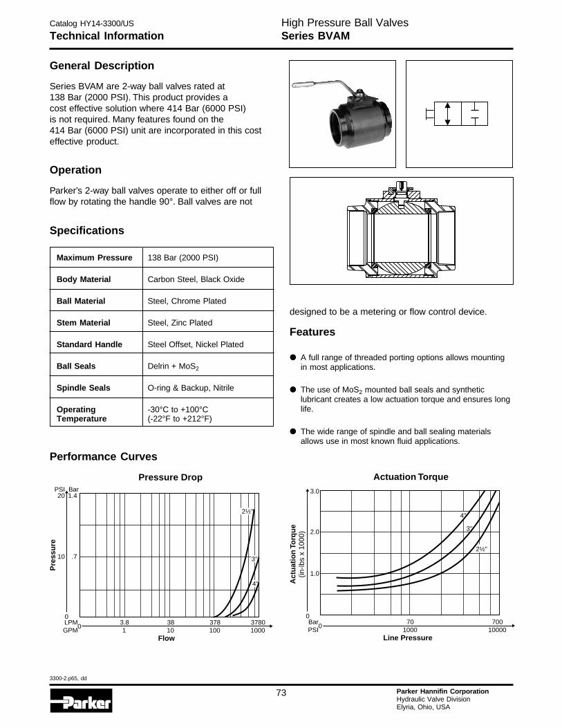
Catalog HY14-3300/US
3300-2.p65, dd
73 Parker Hannifin CorporationHydraulic Valve DivisionElyria, Ohio, USA
Technical InformationHigh Pressure Ball ValvesSeries BVAM
Maximum Pressure 138 Bar (2000 PSI)
Body Material Carbon Steel, Black Oxide
Ball Material Steel, Chrome Plated
Stem Material Steel, Zinc Plated
Standard Handle Steel Offset, Nickel Plated
Ball Seals Delrin + MoS2
Spindle Seals O-ring & Backup, Nitrile
Operating -30°C to +100°CTemperature (-22°F to +212°F)
General Description
Series BVAM are 2-way ball valves rated at138 Bar (2000 PSI). This product provides acost effective solution where 414 Bar (6000 PSI)is not required. Many features found on the414 Bar (6000 PSI) unit are incorporated in this costeffective product.
Operation
Parker’s 2-way ball valves operate to either off or fullflow by rotating the handle 90°. Ball valves are not
Specifications
Performance Curves
designed to be a metering or flow control device.
Features
••••• A full range of threaded porting options allows mountingin most applications.
••••• The use of MoS2 mounted ball seals and syntheticlubricant creates a low actuation torque and ensures longlife.
••••• The wide range of spindle and ball sealing materialsallows use in most known fluid applications.
Pressure Drop
0
10 .7
20 1.4PSI Bar
Pre
ssu
re
2½"
3783.8 381001 10
37801000
Flow
0LPMGPM
3"
4"
Actuation Torque
3"
4"
701000
70010000
Line Pressure
0
0
2.0
1.0
3.0
Act
uat
ion
Torq
ue
(in-lb
s x
1000
)
BarPSI
2½"
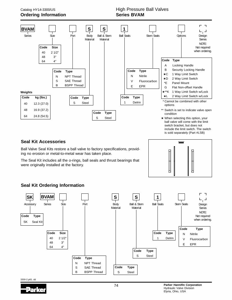
Catalog HY14-3300/US
3300-2.p65, dd
74 Parker Hannifin CorporationHydraulic Valve DivisionElyria, Ohio, USA
H
Ordering InformationHigh Pressure Ball ValvesSeries BVAM
Seal Kit Accessories
Ball Valve Seal Kits restore a ball valve to factory specifications, provid-ing no erosion or metal-to-metal wear has taken place.
The Seal Kit includes all the o-rings, ball seals and thrust bearings thatwere originally installed at the factory.
Seal Kit Ordering Information
Code Type
SK Seal Kit
Code Type
1 Delrin
Code Size
40 2 1/2"
48 3"
64 4"
Code Type
N Nitrile
V Fluorocarbon
E EPR
Code Type
S Steel
Code Type
S Steel
SKAccessory Series Size Port Body
MaterialBall & Stem
MaterialBall Seals Stem Seals Design
SeriesNOTE:
Not requiredwhen ordering.
S S 1
Code Type
A Locking Handle
B Security Locking Handle
★C 1 Way Limit Switch
★D 2 Way Limit Switch
*E Panel Mount
G Flat Non-offset Handle
★**K 1 Way Limit Switch w/Lock
★L 2 Way Limit Switch w/Lock
* Cannot be combined with otheroptions
** Switch is set to indicate valve opencondition
★ When selecting this option, yourball valve will come with the limitswitch bracket, but does notinclude the limit switch. The switchis sold separately (Part #LSB)
Code Type
1 Delrin
Code Size
40 2 1/2"
48 3"
64 4"
Code Type
S Steel
Code Type
N Nitrile
V Fluorocarbon
E EPR
Weights
Code kg (lbs.)
40 12.3 (27.0)
48 16.9 (37.2)
64 24.8 (54.5)Code Type
S Steel
BVAMSeries Size Port Body
MaterialBall & Stem
MaterialBall Seals Stem Seals Options Design
SeriesNOTE:
Not requiredwhen ordering.
S S 1
BVAM
Code Type
N NPT Thread
S SAE Thread
B BSPP Thread
Code Type
N NPT Thread
S SAE Thread
B BSPP Thread
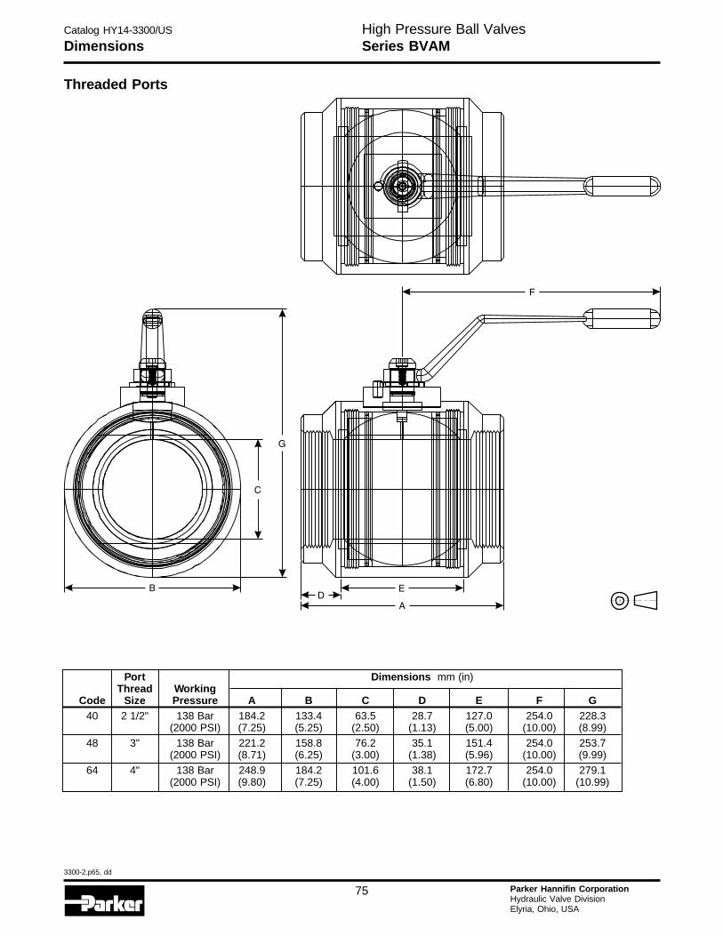
Catalog HY14-3300/US
3300-2.p65, dd
75 Parker Hannifin CorporationHydraulic Valve DivisionElyria, Ohio, USA
DimensionsHigh Pressure Ball ValvesSeries BVAM
Threaded Ports
Port Dimensions mm (in)Thread Working
Code Size Pressure A B C D E F G40 2 1/2" 138 Bar 184.2 133.4 63.5 28.7 127.0 254.0 228.3
(2000 PSI) (7.25) (5.25) (2.50) (1.13) (5.00) (10.00) (8.99)48 3" 138 Bar 221.2 158.8 76.2 35.1 151.4 254.0 253.7
(2000 PSI) (8.71) (6.25) (3.00) (1.38) (5.96) (10.00) (9.99)
64 4" 138 Bar 248.9 184.2 101.6 38.1 172.7 254.0 279.1(2000 PSI) (9.80) (7.25) (4.00) (1.50) (6.80) (10.00) (10.99)
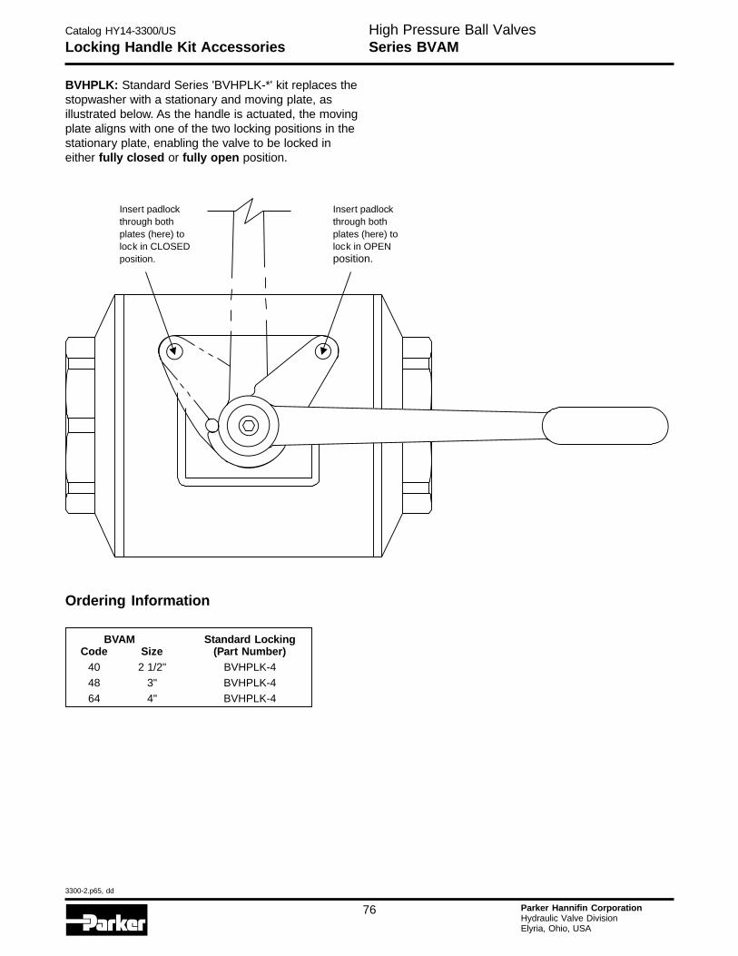
Catalog HY14-3300/US
3300-2.p65, dd
76 Parker Hannifin CorporationHydraulic Valve DivisionElyria, Ohio, USA
H
Locking Handle Kit AccessoriesHigh Pressure Ball ValvesSeries BVAM
BVHPLK: Standard Series 'BVHPLK-*' kit replaces thestopwasher with a stationary and moving plate, asillustrated below. As the handle is actuated, the movingplate aligns with one of the two locking positions in thestationary plate, enabling the valve to be locked ineither fully closed or fully open position.
Ordering Information
BVAM Standard LockingCode Size (Part Number)
40 2 1/2" BVHPLK-448 3" BVHPLK-4
64 4" BVHPLK-4
Insert padlockthrough bothplates (here) tolock in CLOSEDposition.
Insert padlockthrough bothplates (here) tolock in OPENposition.
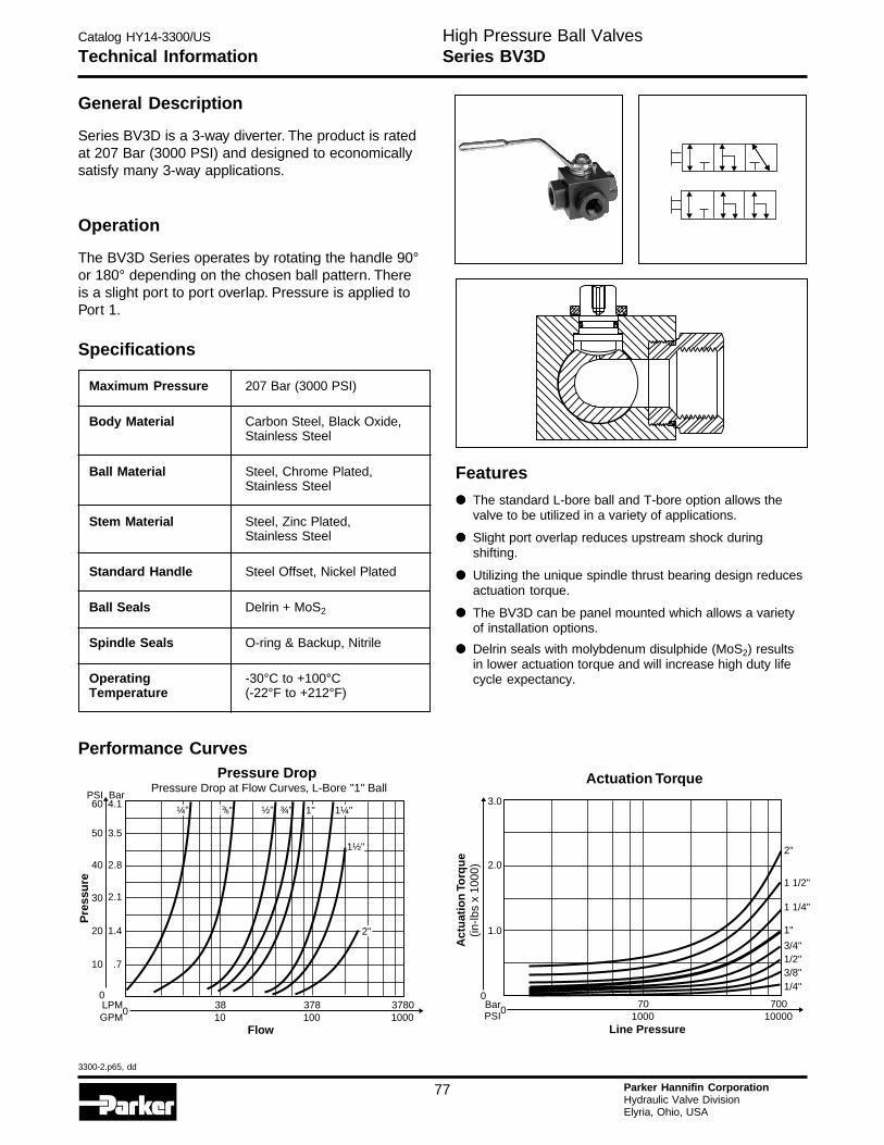
Catalog HY14-3300/US
3300-2.p65, dd
77 Parker Hannifin CorporationHydraulic Valve DivisionElyria, Ohio, USA
Technical InformationHigh Pressure Ball ValvesSeries BV3D
General Description
Series BV3D is a 3-way diverter. The product is ratedat 207 Bar (3000 PSI) and designed to economicallysatisfy many 3-way applications.
Operation
The BV3D Series operates by rotating the handle 90°or 180° depending on the chosen ball pattern. Thereis a slight port to port overlap. Pressure is applied toPort 1.
Specifications
Maximum Pressure 207 Bar (3000 PSI)
Body Material Carbon Steel, Black Oxide,Stainless Steel
Ball Material Steel, Chrome Plated,Stainless Steel
Stem Material Steel, Zinc Plated,Stainless Steel
Standard Handle Steel Offset, Nickel Plated
Ball Seals Delrin + MoS2
Spindle Seals O-ring & Backup, Nitrile
Operating -30°C to +100°CTemperature (-22°F to +212°F)
Performance Curves
3783810010
37801000
Flow
0LPMGPM
Pressure DropPressure Drop at Flow Curves, L-Bore "1" Ball
0
10 .7
20 1.4
30 2.1
40 2.8
50
60PSI
3.5
4.1Bar
Pre
ssu
re
¼" ½" ¾" 1" 1¼"
1½"
2"
38/ "
Actuation Torque
1 1/4"
1 1/2"
2"
1"
1/4"3/8"1/2"3/4"
701000
70010000
00
2.0
1.0
3.0
Act
uat
ion
Torq
ue
(in-lb
s x
1000
)
BarPSI
Line Pressure
Features
••••• The standard L-bore ball and T-bore option allows thevalve to be utilized in a variety of applications.
••••• Slight port overlap reduces upstream shock duringshifting.
••••• Utilizing the unique spindle thrust bearing design reducesactuation torque.
••••• The BV3D can be panel mounted which allows a varietyof installation options.
••••• Delrin seals with molybdenum disulphide (MoS2) resultsin lower actuation torque and will increase high duty lifecycle expectancy.
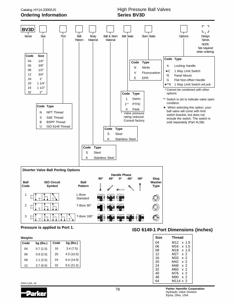
Catalog HY14-3300/US
3300-2.p65, dd
78 Parker Hannifin CorporationHydraulic Valve DivisionElyria, Ohio, USA
H
Ordering InformationHigh Pressure Ball ValvesSeries BV3D
Code Type
N NPT Thread
S SAE Thread
B BSPP Thread
U ISO 6149 Thread
Code Type
A Locking Handle
★C 1 Way Limit Switch
*E Panel Mount
G Flat Non-offset Handle
★**K 1 Way Limit Switch w/Lock
* Cannot be combined with otheroptions
** Switch is set to indicate valve opencondition
★ When selecting this option, yourball valve will come with limitswitch bracket, but does notinclude the switch. The switch issold separately (Part #LSB)
Code Type
1 Delrin
2 * PTFE
4 Peek
Code Type
S Steel
K Stainless Steel
Code Type
N Nitrile
V Fluorocarbon
E EPR
Code Size
04 1/4"
06 3/8"
08 1/2"
12 3/4"
16 1"
20 1 1/4"
24 1 1/2"
32 2"
Weights
Code kg (lbs.)
04 0.7 (1.5)
06 0.9 (2.0)
08 1.1 (2.5)
12 2.7 (6.0)
Code Type
S Steel
K Stainless Steel
Code kg (lbs.)
16 3.4 (7.5)
20 4.5 (10.0)
24 6.4 (14.0)
32 9.5 (21.0)
Diverter Valve Ball Porting Options
BV3DSeries Size Port Ball
PatternBody
MaterialBall & Stem
MaterialBall Seals Options Design
SeriesNOTE:
Not requiredwhen ordering.
Stem Seals
* Valve pressurerating reduced.Consult factory.
ISO 6149-1 Port Dimensions (inches)
Size Thread04 M12 x 1.506 M16 x 1.508 M18 x 1.512 M27 x 216 M33 x 220 M42 x 224 M48 x 232 M60 x 240 M76 x 248 M90 x 264 M114 x 2
Handle Phase90° 45° 0° -45° -90° Stop
Ball ISO Circuit Ball WasherCode Symbol Pattern Type
1 L-BoreStandard
2 T-Bore 90°
3 T-Bore 180°
Pressure is applied to Port 1.
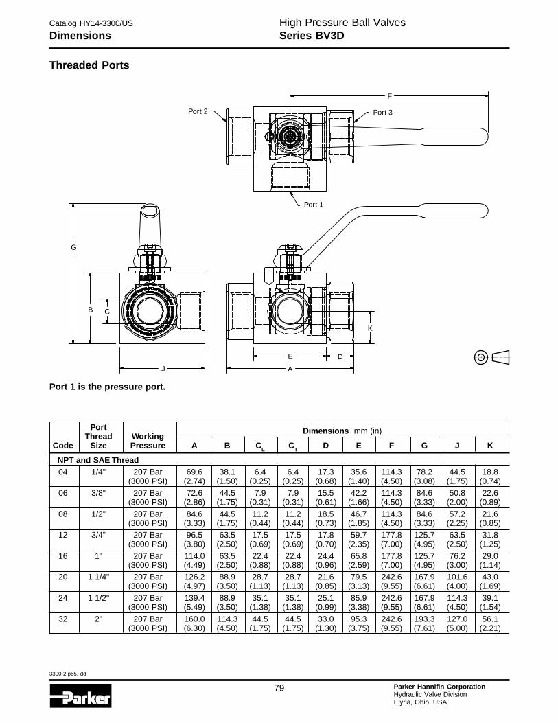
Catalog HY14-3300/US
3300-2.p65, dd
79 Parker Hannifin CorporationHydraulic Valve DivisionElyria, Ohio, USA
DimensionsHigh Pressure Ball ValvesSeries BV3D
Port Dimensions mm (in)Thread Working
Code Size Pressure A B CL CT D E F G J K
NPT and SAE Thread04 1/4" 207 Bar 69.6 38.1 6.4 6.4 17.3 35.6 114.3 78.2 44.5 18.8
(3000 PSI) (2.74) (1.50) (0.25) (0.25) (0.68) (1.40) (4.50) (3.08) (1.75) (0.74)06 3/8" 207 Bar 72.6 44.5 7.9 7.9 15.5 42.2 114.3 84.6 50.8 22.6
(3000 PSI) (2.86) (1.75) (0.31) (0.31) (0.61) (1.66) (4.50) (3.33) (2.00) (0.89)
08 1/2" 207 Bar 84.6 44.5 11.2 11.2 18.5 46.7 114.3 84.6 57.2 21.6(3000 PSI) (3.33) (1.75) (0.44) (0.44) (0.73) (1.85) (4.50) (3.33) (2.25) (0.85)
12 3/4" 207 Bar 96.5 63.5 17.5 17.5 17.8 59.7 177.8 125.7 63.5 31.8(3000 PSI) (3.80) (2.50) (0.69) (0.69) (0.70) (2.35) (7.00) (4.95) (2.50) (1.25)
16 1" 207 Bar 114.0 63.5 22.4 22.4 24.4 65.8 177.8 125.7 76.2 29.0(3000 PSI) (4.49) (2.50) (0.88) (0.88) (0.96) (2.59) (7.00) (4.95) (3.00) (1.14)
20 1 1/4" 207 Bar 126.2 88.9 28.7 28.7 21.6 79.5 242.6 167.9 101.6 43.0(3000 PSI) (4.97) (3.50) (1.13) (1.13) (0.85) (3.13) (9.55) (6.61) (4.00) (1.69)
24 1 1/2" 207 Bar 139.4 88.9 35.1 35.1 25.1 85.9 242.6 167.9 114.3 39.1(3000 PSI) (5.49) (3.50) (1.38) (1.38) (0.99) (3.38) (9.55) (6.61) (4.50) (1.54)
32 2" 207 Bar 160.0 114.3 44.5 44.5 33.0 95.3 242.6 193.3 127.0 56.1(3000 PSI) (6.30) (4.50) (1.75) (1.75) (1.30) (3.75) (9.55) (7.61) (5.00) (2.21)
Threaded Ports
Port 2 Port 3
Port 1
F
K
D
AJ
CB
G
E
Port 1 is the pressure port.
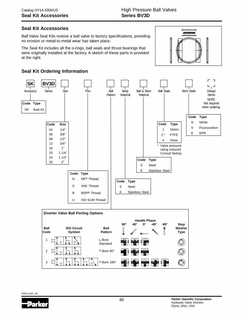
Catalog HY14-3300/US
3300-2.p65, dd
80 Parker Hannifin CorporationHydraulic Valve DivisionElyria, Ohio, USA
H
Seal Kit AccessoriesHigh Pressure Ball ValvesSeries BV3D
Seal Kit Accessories
Ball Valve Seal Kits restore a ball valve to factory specifications, providingno erosion or metal-to-metal wear has taken place.
The Seal Kit includes all the o-rings, ball seals and thrust bearings thatwere originally installed at the factory. A sketch of these parts is providedat the right.
Seal Kit Ordering Information
Code Type
SK Seal Kit
Code Type
N NPT Thread
S SAE Thread
B BSPP Thread
U ISO 6149 Thread
Code Type
1 Delrin
2 * PTFE
4 Peek
Code Type
S Steel
K Stainless Steel
Code Type
N Nitrile
V Fluorocarbon
E EPR
Code Size
04 1/4"
06 3/8"
08 1/2"
12 3/4"
16 1"
20 1 1/4"
24 1 1/2"
32 2"Code Type
S Steel
K Stainless Steel
Handle Phase90° 45° 0° -45° -90° Stop
Ball ISO Circuit Ball WasherCode Symbol Pattern Type
1 L-BoreStandard
2 T-Bore 90°
3 T-Bore 180°
Diverter Valve Ball Porting Options
SK BV3DAccessory Series Size Port Body
MaterialBall & Stem
MaterialBall Seals Stem Seals Design
SeriesNOTE:
Not requiredwhen ordering.
BallPattern
* Valve pressurerating reduced.Consult factory.
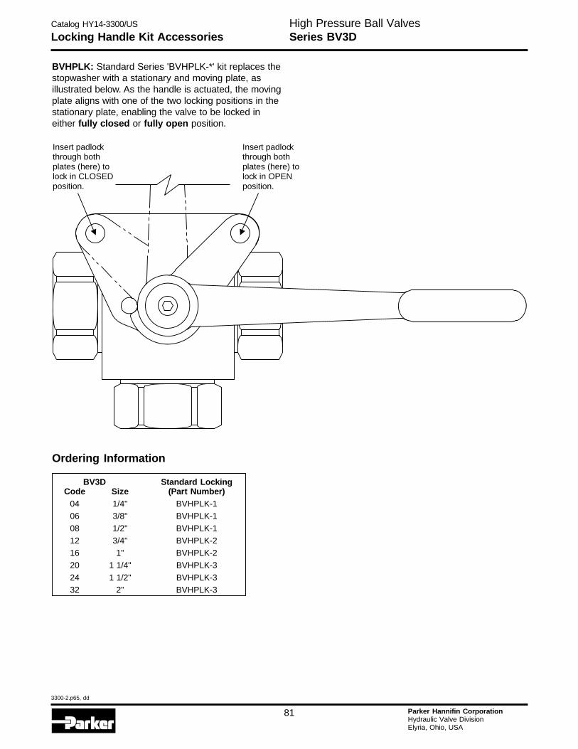
Catalog HY14-3300/US
3300-2.p65, dd
81 Parker Hannifin CorporationHydraulic Valve DivisionElyria, Ohio, USA
Locking Handle Kit AccessoriesHigh Pressure Ball ValvesSeries BV3D
BVHPLK: Standard Series 'BVHPLK-*' kit replaces thestopwasher with a stationary and moving plate, asillustrated below. As the handle is actuated, the movingplate aligns with one of the two locking positions in thestationary plate, enabling the valve to be locked ineither fully closed or fully open position.
Ordering Information
BV3D Standard LockingCode Size (Part Number)
04 1/4" BVHPLK-1
06 3/8" BVHPLK-108 1/2" BVHPLK-1
12 3/4" BVHPLK-216 1" BVHPLK-2
20 1 1/4" BVHPLK-3
24 1 1/2" BVHPLK-332 2" BVHPLK-3
Insert padlockthrough bothplates (here) tolock in CLOSEDposition.
Insert padlockthrough bothplates (here) tolock in OPENposition.
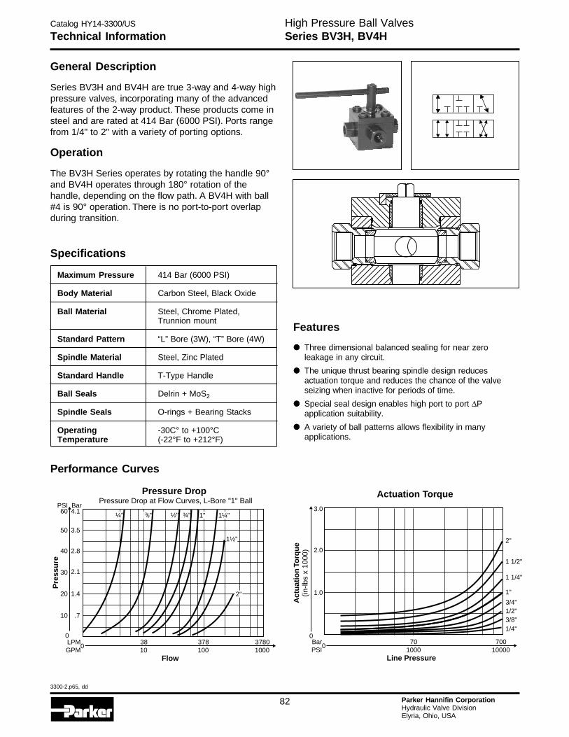
Catalog HY14-3300/US
3300-2.p65, dd
82 Parker Hannifin CorporationHydraulic Valve DivisionElyria, Ohio, USA
H
Technical InformationHigh Pressure Ball ValvesSeries BV3H, BV4H
General Description
Series BV3H and BV4H are true 3-way and 4-way highpressure valves, incorporating many of the advancedfeatures of the 2-way product. These products come insteel and are rated at 414 Bar (6000 PSI). Ports rangefrom 1/4" to 2" with a variety of porting options.
Operation
The BV3H Series operates by rotating the handle 90°and BV4H operates through 180° rotation of thehandle, depending on the flow path. A BV4H with ball#4 is 90° operation. There is no port-to-port overlapduring transition.
Specifications
Maximum Pressure 414 Bar (6000 PSI)
Body Material Carbon Steel, Black Oxide
Ball Material Steel, Chrome Plated,Trunnion mount
Standard Pattern “L” Bore (3W), “T” Bore (4W)
Spindle Material Steel, Zinc Plated
Standard Handle T-Type Handle
Ball Seals Delrin + MoS2
Spindle Seals O-rings + Bearing Stacks
Operating -30C° to +100°CTemperature (-22°F to +212°F)
Performance Curves
3783810010
37801000
Flow
0LPMGPM
Pressure DropPressure Drop at Flow Curves, L-Bore "1" Ball
0
10 .7
20 1.4
30 2.1
40 2.8
50
60PSI
3.5
4.1Bar
Pre
ssu
re
¼" ½" ¾" 1" 1¼"
1½"
2"
38/ "
Actuation Torque
1 1/4"
1 1/2"
2"
1"
1/4"3/8"1/2"3/4"
701000
70010000
Line Pressure
0
0
2.0
1.0
3.0
Act
uat
ion
Torq
ue
(in-lb
s x
1000
)
BarPSI
Features
••••• Three dimensional balanced sealing for near zeroleakage in any circuit.
••••• The unique thrust bearing spindle design reducesactuation torque and reduces the chance of the valveseizing when inactive for periods of time.
••••• Special seal design enables high port to port ΔPapplication suitability.
••••• A variety of ball patterns allows flexibility in manyapplications.
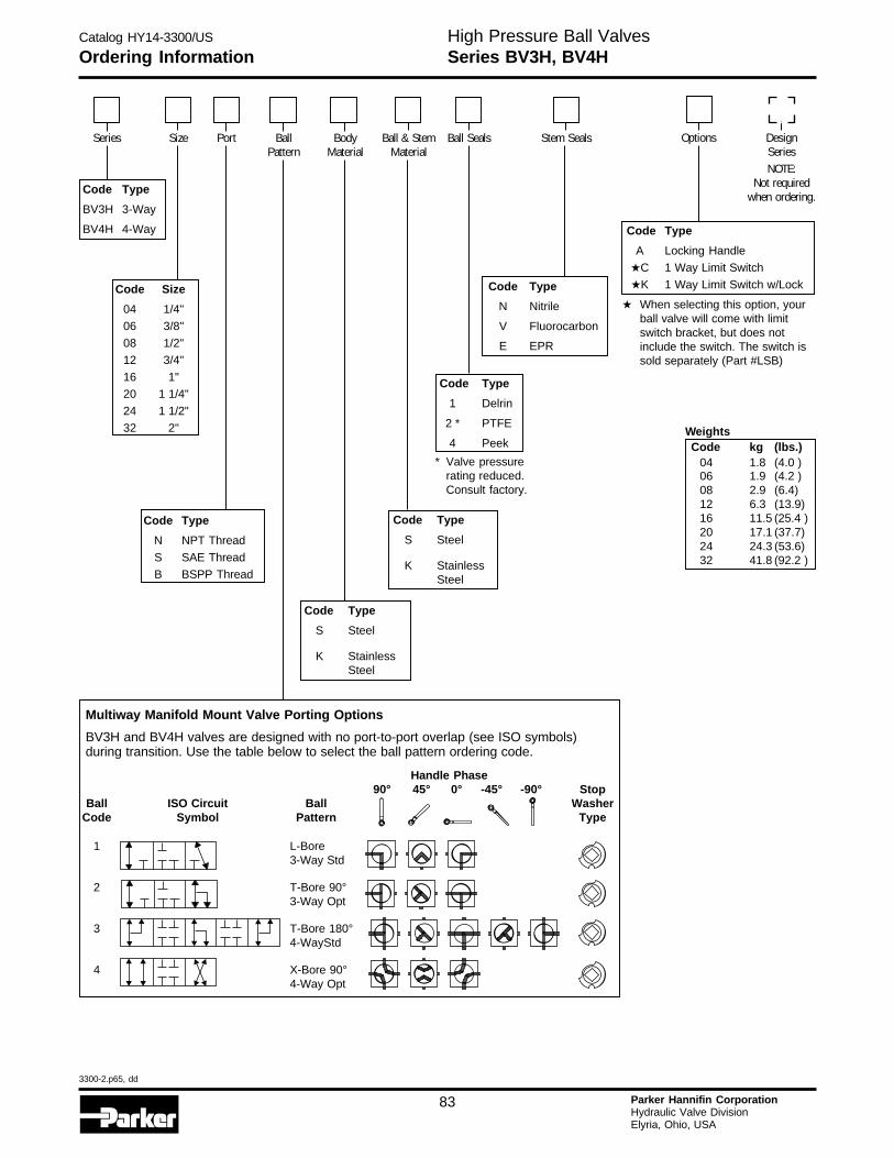
Catalog HY14-3300/US
3300-2.p65, dd
83 Parker Hannifin CorporationHydraulic Valve DivisionElyria, Ohio, USA
Ordering InformationHigh Pressure Ball ValvesSeries BV3H, BV4H
Code Type
BV3H 3-Way
BV4H 4-Way
Code Type
N NPT Thread
S SAE Thread
B BSPP Thread
Code Type
A Locking Handle
★C 1 Way Limit Switch
★K 1 Way Limit Switch w/Lock
★ When selecting this option, yourball valve will come with limitswitch bracket, but does notinclude the switch. The switch issold separately (Part #LSB)
Code Type
1 Delrin
2 * PTFE
4 Peek
Code Type
S Steel
K StainlessSteel
Code Type
N Nitrile
V Fluorocarbon
E EPR
Code Size
04 1/4"
06 3/8"
08 1/2"
12 3/4"
16 1"
20 1 1/4"
24 1 1/2"
32 2"
Handle Phase90° 45° 0° -45° -90° Stop
Ball ISO Circuit Ball WasherCode Symbol Pattern Type
1 L-Bore3-Way Std
2 T-Bore 90°3-Way Opt
3 T-Bore 180°4-WayStd
4 X-Bore 90°4-Way Opt
Code Type
S Steel
K StainlessSteel
Multiway Manifold Mount Valve Porting Options
BV3H and BV4H valves are designed with no port-to-port overlap (see ISO symbols)during transition. Use the table below to select the ball pattern ordering code.
Series Size Port BallPattern
BodyMaterial
Ball & StemMaterial
Ball Seals Options DesignSeriesNOTE:
Not requiredwhen ordering.
Stem Seals
* Valve pressurerating reduced.Consult factory.
WeightsCode kg (lbs.)
04 1.8 (4.0 )06 1.9 (4.2 )08 2.9 (6.4)12 6.3 (13.9)16 11.5 (25.4 )20 17.1 (37.7)24 24.3 (53.6)32 41.8 (92.2 )
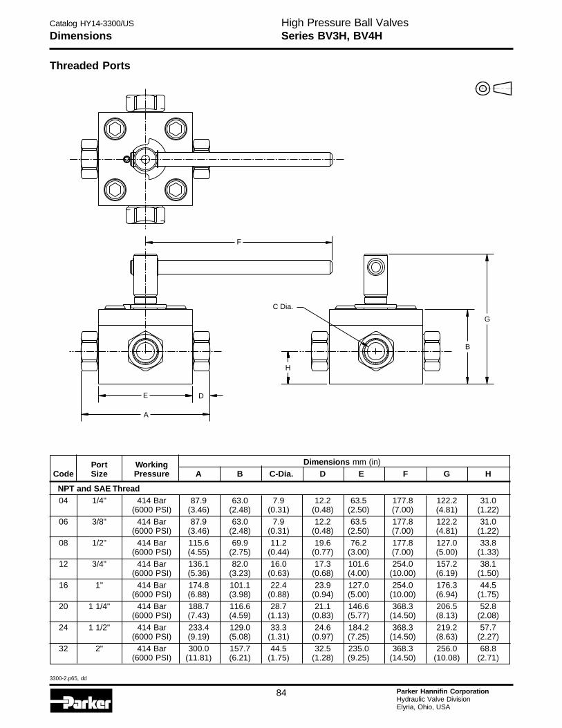
Catalog HY14-3300/US
3300-2.p65, dd
84 Parker Hannifin CorporationHydraulic Valve DivisionElyria, Ohio, USA
H
DimensionsHigh Pressure Ball ValvesSeries BV3H, BV4H
Threaded Ports
Port Working Dimensions mm (in)
Code Size Pressure A B C-Dia. D E F G H
NPT and SAE Thread04 1/4" 414 Bar 87.9 63.0 7.9 12.2 63.5 177.8 122.2 31.0
(6000 PSI) (3.46) (2.48) (0.31) (0.48) (2.50) (7.00) (4.81) (1.22)06 3/8" 414 Bar 87.9 63.0 7.9 12.2 63.5 177.8 122.2 31.0
(6000 PSI) (3.46) (2.48) (0.31) (0.48) (2.50) (7.00) (4.81) (1.22)
08 1/2" 414 Bar 115.6 69.9 11.2 19.6 76.2 177.8 127.0 33.8(6000 PSI) (4.55) (2.75) (0.44) (0.77) (3.00) (7.00) (5.00) (1.33)
12 3/4" 414 Bar 136.1 82.0 16.0 17.3 101.6 254.0 157.2 38.1(6000 PSI) (5.36) (3.23) (0.63) (0.68) (4.00) (10.00) (6.19) (1.50)
16 1" 414 Bar 174.8 101.1 22.4 23.9 127.0 254.0 176.3 44.5(6000 PSI) (6.88) (3.98) (0.88) (0.94) (5.00) (10.00) (6.94) (1.75)
20 1 1/4" 414 Bar 188.7 116.6 28.7 21.1 146.6 368.3 206.5 52.8(6000 PSI) (7.43) (4.59) (1.13) (0.83) (5.77) (14.50) (8.13) (2.08)
24 1 1/2" 414 Bar 233.4 129.0 33.3 24.6 184.2 368.3 219.2 57.7(6000 PSI) (9.19) (5.08) (1.31) (0.97) (7.25) (14.50) (8.63) (2.27)
32 2" 414 Bar 300.0 157.7 44.5 32.5 235.0 368.3 256.0 68.8(6000 PSI) (11.81) (6.21) (1.75) (1.28) (9.25) (14.50) (10.08) (2.71)
F
H
B
G
D
A
E
C Dia.
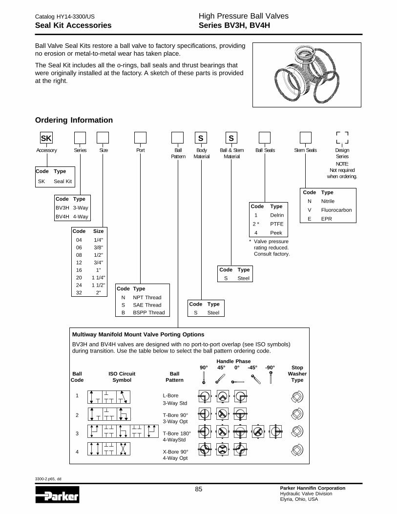
Catalog HY14-3300/US
3300-2.p65, dd
85 Parker Hannifin CorporationHydraulic Valve DivisionElyria, Ohio, USA
Seal Kit AccessoriesHigh Pressure Ball ValvesSeries BV3H, BV4H
Code Type
BV3H 3-Way
BV4H 4-Way
Code Type
1 Delrin
2 * PTFE
4 Peek
Code Type
S Steel
Code Type
N Nitrile
V Fluorocarbon
E EPR
Code Size
04 1/4"
06 3/8"
08 1/2"
12 3/4"
16 1"
20 1 1/4"
24 1 1/2"
32 2"
Code Type
S Steel
Ordering Information
Code Type
SK Seal Kit
Handle Phase90° 45° 0° -45° -90° Stop
Ball ISO Circuit Ball WasherCode Symbol Pattern Type
1 L-Bore
3-Way Std
2 T-Bore 90°3-Way Opt
3 T-Bore 180°4-WayStd
4 X-Bore 90°4-Way Opt
Multiway Manifold Mount Valve Porting Options
BV3H and BV4H valves are designed with no port-to-port overlap (see ISO symbols)during transition. Use the table below to select the ball pattern ordering code.
Code Type
N NPT Thread
S SAE Thread
B BSPP Thread
SKAccessory Series Size Port Body
MaterialBall & Stem
MaterialBall Seals Stem Seals Design
SeriesNOTE:
Not requiredwhen ordering.
BallPattern
S S
* Valve pressurerating reduced.Consult factory.
Ball Valve Seal Kits restore a ball valve to factory specifications, providingno erosion or metal-to-metal wear has taken place.
The Seal Kit includes all the o-rings, ball seals and thrust bearings thatwere originally installed at the factory. A sketch of these parts is providedat the right.

Catalog HY14-3300/US
3300-2.p65, dd
86 Parker Hannifin CorporationHydraulic Valve DivisionElyria, Ohio, USA
H
Locking Handle Kit AccessoriesHigh Pressure Ball ValvesSeries BV3H, BV4H
BVHPLH: Standard Series 'BVHPLH-*' kit replaces thestopwasher with a stationary and moving plate, asillustrated below. As the handle is actuated, the movingplate aligns with one of the two locking positions in thestationary plate, enabling the valve to be locked ineither fully closed or fully open position.
Ordering Information
BV3H and BV4H Standard LockingCode Size (Part Number)
04 1/4" BVHPLH-206 3/8" BVHPLH-2
08 1/2" BVHPLH-3
12 3/4" BVHPLH-416 1" BVHPLH-5
20 1 1/4" BVHPLH-624 1 1/2" BVHPLH-7
32 2" BVHPLH-8
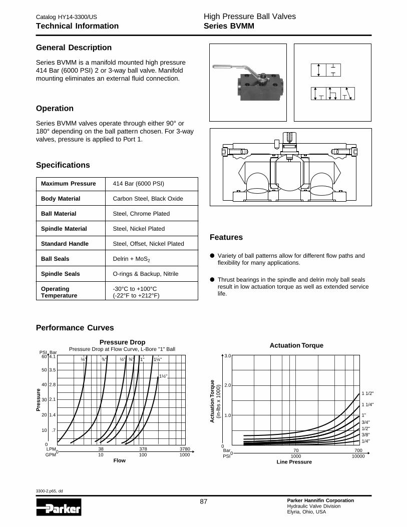
Catalog HY14-3300/US
3300-2.p65, dd
87 Parker Hannifin CorporationHydraulic Valve DivisionElyria, Ohio, USA
Technical InformationHigh Pressure Ball ValvesSeries BVMM
Maximum Pressure 414 Bar (6000 PSI)
Body Material Carbon Steel, Black Oxide
Ball Material Steel, Chrome Plated
Spindle Material Steel, Nickel Plated
Standard Handle Steel, Offset, Nickel Plated
Ball Seals Delrin + MoS2
Spindle Seals O-rings & Backup, Nitrile
Operating -30°C to +100°CTemperature (-22°F to +212°F)
General Description
Series BVMM is a manifold mounted high pressure414 Bar (6000 PSI) 2 or 3-way ball valve. Manifoldmounting eliminates an external fluid connection.
Operation
Series BVMM valves operate through either 90° or180° depending on the ball pattern chosen. For 3-wayvalves, pressure is applied to Port 1.
Specifications
Performance Curves
3783810010
37801000
Flow
0LPMGPM
Pressure DropPressure Drop at Flow Curve, L-Bore "1" Ball
0
10 .7
20 1.4
30 2.1
40 2.8
50
60PSI
3.5
4.1Bar
Pre
ssu
re
¼" ½" ¾" 1" 1¼"
1½"
38/ "
Actuation Torque
1 1/4"
1 1/2"
1"
1/4"3/8"1/2"3/4"
701000
70010000
Line Pressure
0
0
2.0
1.0
3.0
Act
uat
ion
Torq
ue
(in-lb
s x
1000
)
BarPSI
Features
••••• Variety of ball patterns allow for different flow paths andflexibility for many applications.
••••• Thrust bearings in the spindle and delrin moly ball sealsresult in low actuation torque as well as extended servicelife.
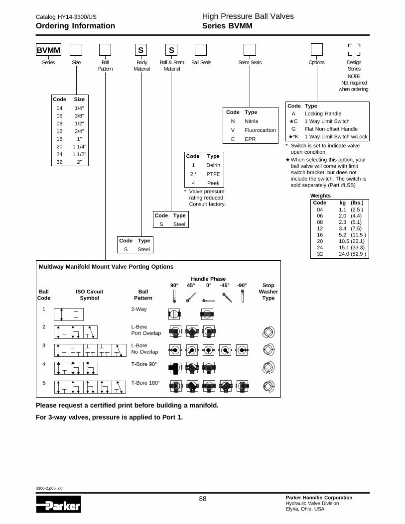
Catalog HY14-3300/US
3300-2.p65, dd
88 Parker Hannifin CorporationHydraulic Valve DivisionElyria, Ohio, USA
H
High Pressure Ball ValvesSeries BVMMOrdering Information
Handle Phase90° 45° 0° -45° -90° Stop
Ball ISO Circuit Ball WasherCode Symbol Pattern Type
1 2-Way
2 L-BorePort Overlap
3 L-BoreNo Overlap
4 T-Bore 90°
5 T-Bore 180°
Multiway Manifold Mount Valve Porting Options
Code Type
1 Delrin
2 * PTFE
4 Peek
Code Type
S Steel
Code Size
04 1/4"
06 3/8"
08 1/2"
12 3/4"
16 1"
20 1 1/4"
24 1 1/2"
32 2"
Code Type
S Steel
Code TypeA Locking Handle
★C 1 Way Limit Switch
G Flat Non-offset Handle
★*K 1 Way Limit Switch w/Lock
* Switch is set to indicate valveopen condition
★ When selecting this option, yourball valve will come with limitswitch bracket, but does notinclude the switch. The switch issold separately (Part #LSB)
Code Type
N Nitrile
V Fluorocarbon
E EPR
BVMMSeries Size Ball
PatternBody
MaterialBall & Stem
MaterialBall Seals Options Design
SeriesNOTE:
Not requiredwhen ordering.
Stem Seals
S S
Please request a certified print before building a manifold.
For 3-way valves, pressure is applied to Port 1.
* Valve pressurerating reduced.Consult factory.
WeightsCode kg (lbs.)
04 1.1 (2.5 )06 2.0 (4.4)08 2.3 (5.1)12 3.4 (7.5)16 5.2 (11.5 )20 10.5 (23.1)24 15.1 (33.3)32 24.0 (52.9 )

Catalog HY14-3300/US
3300-2.p65, dd
89 Parker Hannifin CorporationHydraulic Valve DivisionElyria, Ohio, USA
High Pressure Ball ValvesSeries BVMMDimensions
Manifold Mounted
Port Working Dimensions mm (in)
Code Size Pressure A B CL D E F G H J K
BVMM 2-Way and 3-Way Manifold Mounted
041 1/4" 414 Bar 66.5 38.1 6.1 9.5 50.8 114.3 78.2 42.0 n/a 35.0(6000 PSI) (2.62) (1.50) (0.24) (0.375) (2.00) (4.50) (3.08) (1.653) (n/a) (1.377)
061 3/8" 414 Bar 81.8 50.0 9.7 9.5 57.2 114.3 90.2 55.0 n/a 40.0(6000 PSI) (3.22) (1.97) (0.38) (0.375) (2.25) (4.50) (3.55) (2.165) (n/a) (1.575)
08 1/2" 414 Bar 106.1 50.0 13.0 9.5 57.2 114.3 89.9 83.0 41.5 45.0(6000 PSI) (4.00) (1.97) (0.51) (0.375) (2.25) (4.50) (3.54) (3.267) (1.634) (1.771)
12 3/4" 414 Bar 141.5 69.3 20.1 9.5 69.9 177.8 131.6 97.0 48.5 51.0(6000 PSI) (5.57) (2.73) (0.79) (0.375) (2.75) (7.00) (5.18) (3.818) (1.909) (2.007)
16 1" 414 Bar 156.5 81.0 23.9 9.5 82.6 177.8 143.0 115.0 57.5 60.0(6000 PSI) (6.16) (3.19) (0.94) (0.375) (3.25) (7.00) (5.63) (4.528) (2.264) (2.362)
20 1 1/4" 414 Bar 180.3 100.1 31.8 12.7 101.6 254.0 179.1 136.0 68.0 78.0(6000 PSI) (7.10) (3.94) (1.25) (0.50) (4.00) (10.00) (7.05) (5.354) (2.677) (3.070)
24 1 1/2" 414 Bar 196.1 100.3 38.1 17.5 127.0 254.0 179.6 112.0 55.9 95.0(6000 PSI) (7.72) (3.95) (1.50) (0.69) (5.00) (10.00) (7.07) (4.409) (2.199) (3.740)
32 2" 414 Bar 246.9 124.0 47.8 22.4 152.4 254.0 202.9 136.0 68.2 112.0(6000 PSI) (9.72) (4.88) (1.88) (0.88) (6.00) (10.00) (7.99) (5.354) (2.684) (4.409)
NOTES: (1) These sizes use only the four outside mounting holes. Dimension J is not applicable.(2) Ball portings for multiway valves are somewhat smaller than their 2-way counterparts. Please refer to dimension C to
confirm suitability.
Please request a certified print before building a manifold.
D
F
G
B
A
H
J
KE
CL
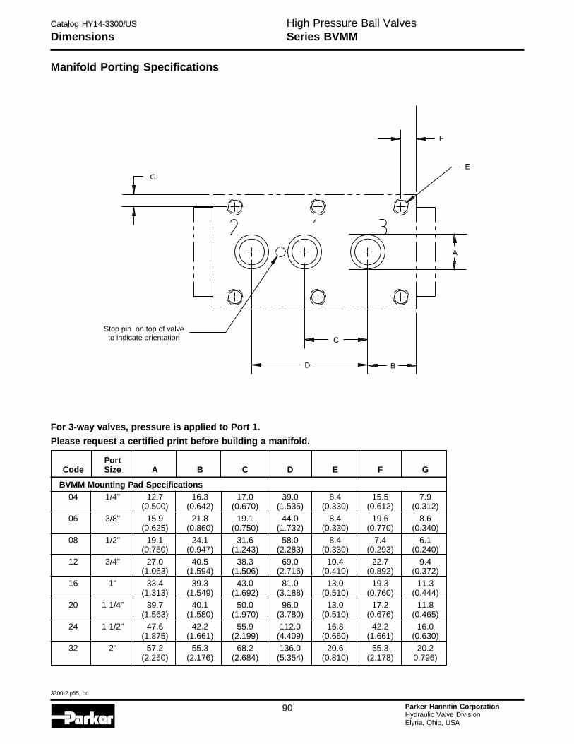
Catalog HY14-3300/US
3300-2.p65, dd
90 Parker Hannifin CorporationHydraulic Valve DivisionElyria, Ohio, USA
H
High Pressure Ball ValvesSeries BVMMDimensions
Manifold Porting Specifications
PortCode Size A B C D E F G
BVMM Mounting Pad Specifications04 1/4" 12.7 16.3 17.0 39.0 8.4 15.5 7.9
(0.500) (0.642) (0.670) (1.535) (0.330) (0.612) (0.312)
06 3/8" 15.9 21.8 19.1 44.0 8.4 19.6 8.6(0.625) (0.860) (0.750) (1.732) (0.330) (0.770) (0.340)
08 1/2" 19.1 24.1 31.6 58.0 8.4 7.4 6.1(0.750) (0.947) (1.243) (2.283) (0.330) (0.293) (0.240)
12 3/4" 27.0 40.5 38.3 69.0 10.4 22.7 9.4(1.063) (1.594) (1.506) (2.716) (0.410) (0.892) (0.372)
16 1" 33.4 39.3 43.0 81.0 13.0 19.3 11.3(1.313) (1.549) (1.692) (3.188) (0.510) (0.760) (0.444)
20 1 1/4" 39.7 40.1 50.0 96.0 13.0 17.2 11.8(1.563) (1.580) (1.970) (3.780) (0.510) (0.676) (0.465)
24 1 1/2" 47.6 42.2 55.9 112.0 16.8 42.2 16.0(1.875) (1.661) (2.199) (4.409) (0.660) (1.661) (0.630)
32 2" 57.2 55.3 68.2 136.0 20.6 55.3 20.2(2.250) (2.176) (2.684) (5.354) (0.810) (2.178) 0.796)
Please request a certified print before building a manifold.
Stop pin on top of valveto indicate orientation
BD
C
F
EG
A
For 3-way valves, pressure is applied to Port 1.
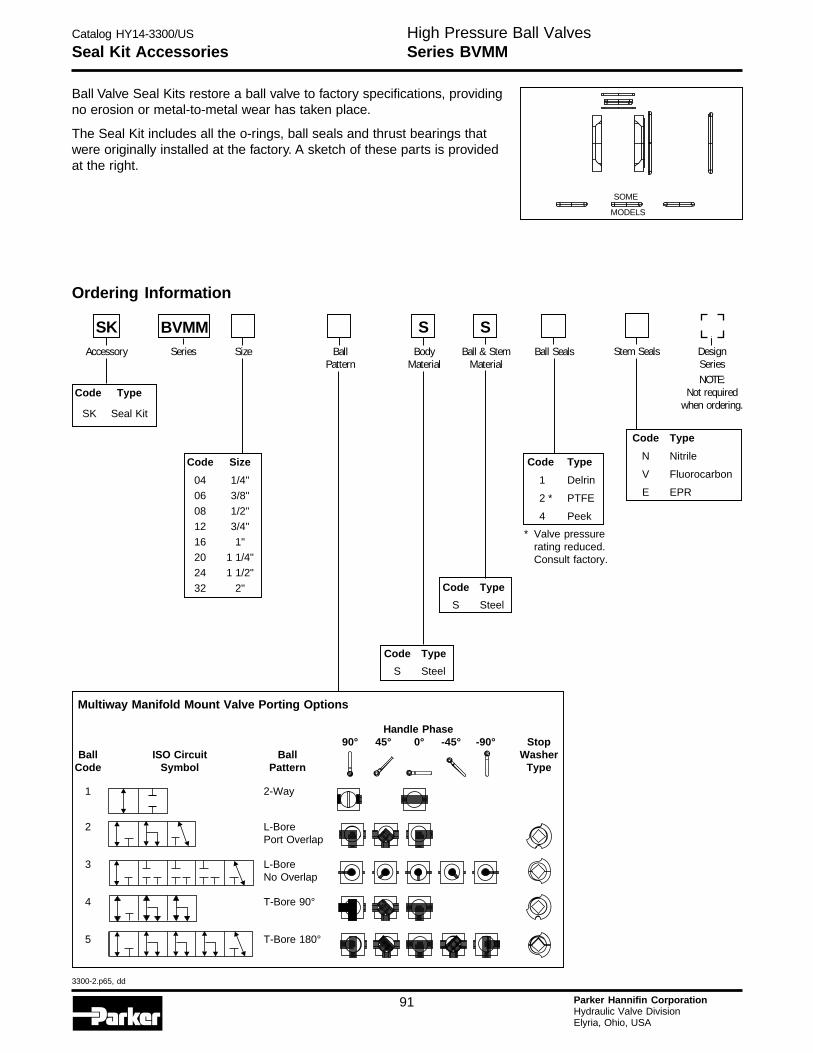
Catalog HY14-3300/US
3300-2.p65, dd
91 Parker Hannifin CorporationHydraulic Valve DivisionElyria, Ohio, USA
High Pressure Ball ValvesSeries BVMMSeal Kit Accessories
Code Size
04 1/4"
06 3/8"
08 1/2"
12 3/4"
16 1"
20 1 1/4"
24 1 1/2"
32 2"
Ball Valve Seal Kits restore a ball valve to factory specifications, providingno erosion or metal-to-metal wear has taken place.
The Seal Kit includes all the o-rings, ball seals and thrust bearings thatwere originally installed at the factory. A sketch of these parts is providedat the right.
Ordering Information
Code Type
1 Delrin
2 * PTFE
4 Peek
Code Type
S Steel
Code Type
N Nitrile
V Fluorocarbon
E EPR
Code Type
S Steel
Code Type
SK Seal Kit
Handle Phase90° 45° 0° -45° -90° Stop
Ball ISO Circuit Ball WasherCode Symbol Pattern Type
1 2-Way
2 L-BorePort Overlap
3 L-BoreNo Overlap
4 T-Bore 90°
5 T-Bore 180°
Multiway Manifold Mount Valve Porting Options
SKAccessory Series Size Body
MaterialBall & Stem
MaterialBall Seals Stem Seals Design
SeriesNOTE:
Not requiredwhen ordering.
BallPattern
S SBVMM
* Valve pressurerating reduced.Consult factory.
SOME
MODELS
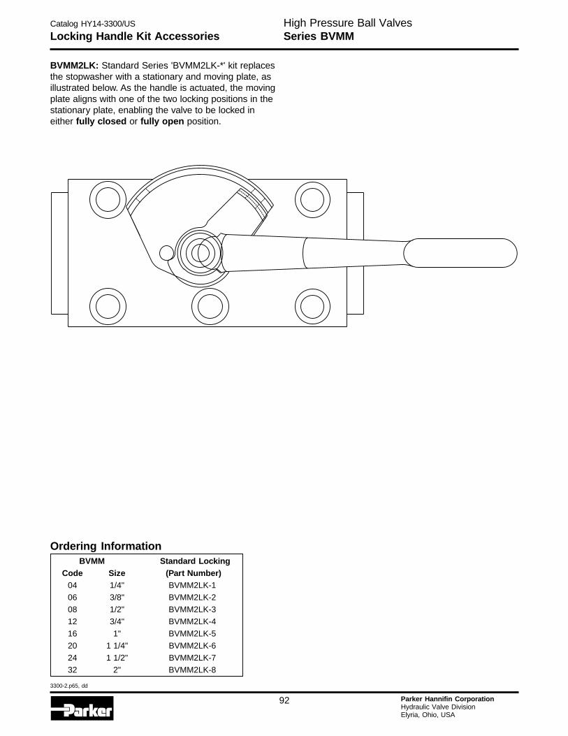
Catalog HY14-3300/US
3300-2.p65, dd
92 Parker Hannifin CorporationHydraulic Valve DivisionElyria, Ohio, USA
H
Locking Handle Kit AccessoriesHigh Pressure Ball ValvesSeries BVMM
BVMM2LK: Standard Series 'BVMM2LK-*' kit replacesthe stopwasher with a stationary and moving plate, asillustrated below. As the handle is actuated, the movingplate aligns with one of the two locking positions in thestationary plate, enabling the valve to be locked ineither fully closed or fully open position.
Ordering InformationBVMM Standard Locking
Code Size (Part Number)04 1/4" BVMM2LK-1
06 3/8" BVMM2LK-2
08 1/2" BVMM2LK-312 3/4" BVMM2LK-4
16 1" BVMM2LK-520 1 1/4" BVMM2LK-6
24 1 1/2" BVMM2LK-7
32 2" BVMM2LK-8
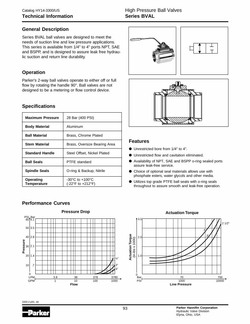
Catalog HY14-3300/US
3300-2.p65, dd
93 Parker Hannifin CorporationHydraulic Valve DivisionElyria, Ohio, USA
High Pressure Ball ValvesSeries BVALTechnical Information
Maximum Pressure 28 Bar (400 PSI)
Body Material Aluminum
Ball Material Brass, Chrome Plated
Stem Material Brass, Oversize Bearing Area
Standard Handle Steel Offset, Nickel Plated
Ball Seals PTFE standard
Spindle Seals O-ring & Backup, Nitrile
Operating -30°C to +100°CTemperature (-22°F to +212°F)
General Description
Series BVAL ball valves are designed to meet theneeds of suction line and low pressure applications.This series is available from 1/4" to 4" ports NPT, SAEand BSPP, and is designed to assure leak free hydrau-lic suction and return line durability.
Operation
Parker’s 2-way ball valves operate to either off or fullflow by rotating the handle 90°. Ball valves are notdesigned to be a metering or flow control device.
Specifications
Performance Curves
Features
••••• Unrestricted bore from 1/4" to 4".
••••• Unrestricted flow and cavitation eliminated.
••••• Availability of NPT, SAE and BSPP o-ring sealed portsassure leak-free service.
••••• Choice of optional seal materials allows use withphosphate esters, water glycols and other media.
••••• Utilizes top grade PTFE ball seats with o-ring sealsthroughout to assure smooth and leak-free operation.
3"4"
Pressure Drop
0
10 .7
20 1.4
30 2.1
40 2.8
50
60PSI
3.5
4.1Bar
Pre
ssu
re
2½"
3783.8 381001 10
37801000
Flow
0LPMGPM
Actuation Torque
3"
4"
2 1/2"
701000
70010000
Line Pressure
0
0
2.0
1.0
3.0
Act
uat
ion
Torq
ue
(in-lb
s x
1000
)
BarPSI
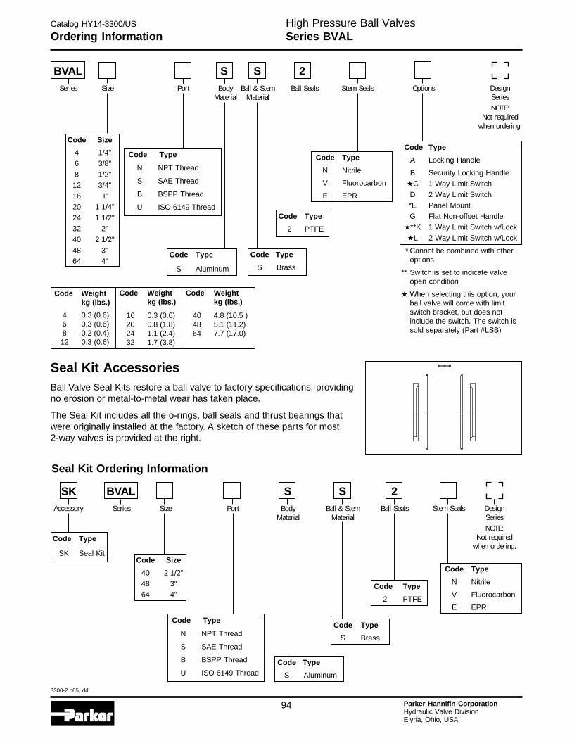
Catalog HY14-3300/US
3300-2.p65, dd
94 Parker Hannifin CorporationHydraulic Valve DivisionElyria, Ohio, USA
H
Ordering InformationHigh Pressure Ball ValvesSeries BVAL
Seal Kit AccessoriesBall Valve Seal Kits restore a ball valve to factory specifications, providingno erosion or metal-to-metal wear has taken place.
The Seal Kit includes all the o-rings, ball seals and thrust bearings thatwere originally installed at the factory. A sketch of these parts for most2-way valves is provided at the right.
Seal Kit Ordering Information
Code Type
SK Seal Kit
Code Type
2 PTFE
Code Type
S Aluminum
Code Type
N Nitrile
V Fluorocarbon
E EPR
Code Size
40 2 1/2"
48 3"
64 4"
Code Type
S Brass
SK BVALAccessory Series Size Body
MaterialBall & Stem
MaterialBall Seals Stem Seals Design
SeriesNOTE:
Not requiredwhen ordering.
Port
S S 2
Code Type
N NPT Thread
S SAE Thread
B BSPP Thread
U ISO 6149 Thread
Code Type
A Locking Handle
B Security Locking Handle
★C 1 Way Limit Switch
D 2 Way Limit Switch
*E Panel Mount
G Flat Non-offset Handle
★**K 1 Way Limit Switch w/Lock
★L 2 Way Limit Switch w/Lock
* Cannot be combined with otheroptions
** Switch is set to indicate valveopen condition
★ When selecting this option, yourball valve will come with limitswitch bracket, but does notinclude the switch. The switch issold separately (Part #LSB)
Code Type
2 PTFE
Code Type
S Aluminum
Code Type
N Nitrile
V Fluorocarbon
E EPR
Code Type
S Brass
Code Size
4 1/4"
6 3/8"
8 1/2"
12 3/4"
16 1'
20 1 1/4"
24 1 1/2"
32 2"
40 2 1/2"
48 3"
64 4"
BVALSeries Size Port Body
MaterialBall & Stem
MaterialBall Seals Options Design
SeriesNOTE:
Not requiredwhen ordering.
Stem Seals
S S 2
Code Weightkg (lbs.)
4 0.3 (0.6)6 0.3 (0.6)8 0.2 (0.4)12 0.3 (0.6)
16 0.3 (0.6)20 0.8 (1.8)24 1.1 (2.4)32 1.7 (3.8)
Code Weightkg (lbs.)
40 4.8 (10.5 )48 5.1 (11.2)64 7.7 (17.0)
Code Weightkg (lbs.)
Code Type
N NPT Thread
S SAE Thread
B BSPP Thread
U ISO 6149 Thread
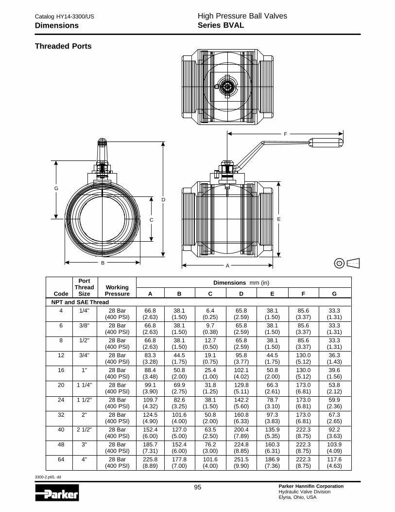
Catalog HY14-3300/US
3300-2.p65, dd
95 Parker Hannifin CorporationHydraulic Valve DivisionElyria, Ohio, USA
High Pressure Ball ValvesSeries BVALDimensions
Threaded Ports
F
D
A
EC
G
B
Port Dimensions mm (in)Thread Working
Code Size Pressure A B C D E F GNPT and SAE Thread
4 1/4" 28 Bar 66.8 38.1 6.4 65.8 38.1 85.6 33.3(400 PSI) (2.63) (1.50) (0.25) (2.59) (1.50) (3.37) (1.31)
6 3/8" 28 Bar 66.8 38.1 9.7 65.8 38.1 85.6 33.3(400 PSI) (2.63) (1.50) (0.38) (2.59) (1.50) (3.37) (1.31)
8 1/2" 28 Bar 66.8 38.1 12.7 65.8 38.1 85.6 33.3(400 PSI) (2.63) (1.50) (0.50) (2.59) (1.50) (3.37) (1.31)
12 3/4" 28 Bar 83.3 44.5 19.1 95.8 44.5 130.0 36.3(400 PSI) (3.28) (1.75) (0.75) (3.77) (1.75) (5.12) (1.43)
16 1" 28 Bar 88.4 50.8 25.4 102.1 50.8 130.0 39.6(400 PSI) (3.48) (2.00) (1.00) (4.02) (2.00) (5.12) (1.56)
20 1 1/4" 28 Bar 99.1 69.9 31.8 129.8 66.3 173.0 53.8(400 PSI) (3.90) (2.75) (1.25) (5.11) (2.61) (6.81) (2.12)
24 1 1/2" 28 Bar 109.7 82.6 38.1 142.2 78.7 173.0 59.9(400 PSI) (4.32) (3.25) (1.50) (5.60) (3.10) (6.81) (2.36)
32 2" 28 Bar 124.5 101.6 50.8 160.8 97.3 173.0 67.3(400 PSI) (4.90) (4.00) (2.00) (6.33) (3.83) (6.81) (2.65)
40 2 1/2" 28 Bar 152.4 127.0 63.5 200.4 135.9 222.3 92.2(400 PSI) (6.00) (5.00) (2.50) (7.89) (5.35) (8.75) (3.63)
48 3" 28 Bar 185.7 152.4 76.2 224.8 160.3 222.3 103.9(400 PSI) (7.31) (6.00) (3.00) (8.85) (6.31) (8.75) (4.09)
64 4" 28 Bar 225.8 177.8 101.6 251.5 186.9 222.3 117.6(400 PSI) (8.89) (7.00) (4.00) (9.90) (7.36) (8.75) (4.63)
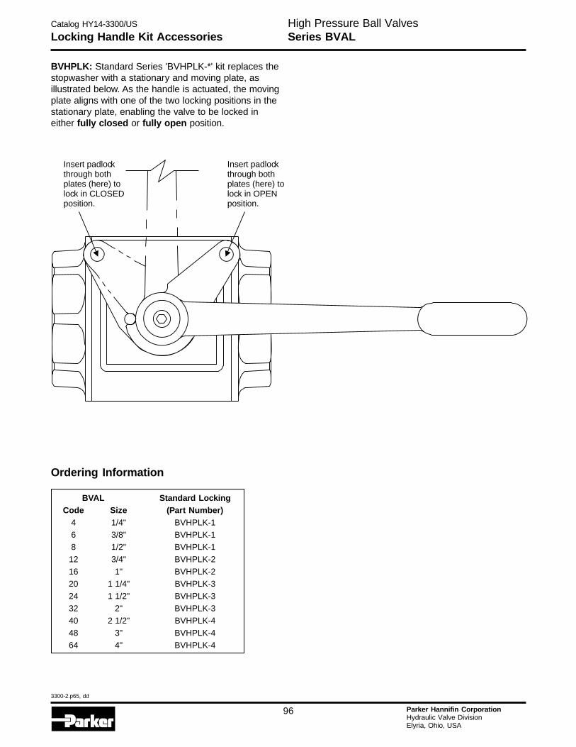
Catalog HY14-3300/US
3300-2.p65, dd
96 Parker Hannifin CorporationHydraulic Valve DivisionElyria, Ohio, USA
H
Locking Handle Kit AccessoriesHigh Pressure Ball ValvesSeries BVAL
BVHPLK: Standard Series 'BVHPLK-*' kit replaces thestopwasher with a stationary and moving plate, asillustrated below. As the handle is actuated, the movingplate aligns with one of the two locking positions in thestationary plate, enabling the valve to be locked ineither fully closed or fully open position.
Ordering Information
BVAL Standard LockingCode Size (Part Number)
4 1/4" BVHPLK-1
6 3/8" BVHPLK-18 1/2" BVHPLK-1
12 3/4" BVHPLK-2
16 1" BVHPLK-220 1 1/4" BVHPLK-3
24 1 1/2" BVHPLK-332 2" BVHPLK-3
40 2 1/2" BVHPLK-4
48 3" BVHPLK-464 4" BVHPLK-4
Insert padlockthrough bothplates (here) tolock in CLOSEDposition.
Insert padlockthrough bothplates (here) tolock in OPENposition.
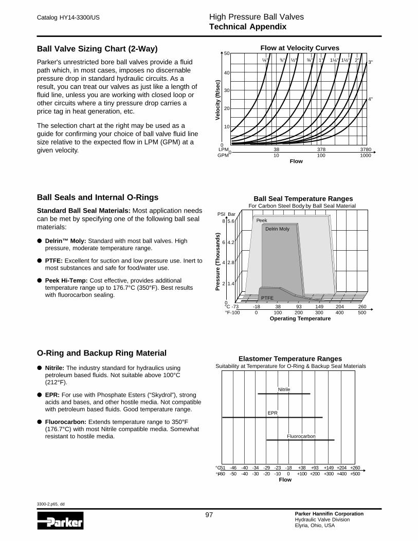
Catalog HY14-3300/US
3300-2.p65, dd
97 Parker Hannifin CorporationHydraulic Valve DivisionElyria, Ohio, USA
High Pressure Ball ValvesTechnical Appendix
Ball Valve Sizing Chart (2-Way)
Parker's unrestricted bore ball valves provide a fluidpath which, in most cases, imposes no discernablepressure drop in standard hydraulic circuits. As aresult, you can treat our valves as just like a length offluid line, unless you are working with closed loop orother circuits where a tiny pressure drop carries aprice tag in heat generation, etc.
The selection chart at the right may be used as aguide for confirming your choice of ball valve fluid linesize relative to the expected flow in LPM (GPM) at agiven velocity.
Ball Seals and Internal O-Rings
Standard Ball Seal Materials: Most application needscan be met by specifying one of the following ball sealmaterials:
••••• Delrin™ Moly: Standard with most ball valves. Highpressure, moderate temperature range.
••••• PTFE: Excellent for suction and low pressure use. Inert tomost substances and safe for food/water use.
••••• Peek Hi-Temp: Cost effective, provides additionaltemperature range up to 176.7°C (350°F). Best resultswith fluorocarbon sealing.
O-Ring and Backup Ring Material
••••• Nitrile: The industry standard for hydraulics usingpetroleum based fluids. Not suitable above 100°C(212°F).
••••• EPR: For use with Phosphate Esters (“Skydrol”), strongacids and bases, and other hostile media. Not compatiblewith petroleum based fluids. Good temperature range.
••••• Fluorocarbon: Extends temperature range to 350°F(176.7°C) with most Nitrile compatible media. Somewhatresistant to hostile media.
Flow at Velocity Curves
0
10
20
30
40
50
Vel
ocity
(ft/s
ec)
3783810010
37801000
Flow
0LPMGPM
¼" ½" ¾" 1" 1¼" 1½" 2" 3"
4"
38/ "
Ball Seal Temperature RangesFor Carbon Steel Body, by Ball Seal Material
149 20438 93-18-73300 400100 2000-100
260500
Operating Temperature
°C°F
0
2
4
1.4
2.8
6 4.2
8 5.6
PSI BarP
ress
ure
(T
ho
usa
nd
s)
Delrin Moly
Peek
PTFE
Elastomer Temperature RangesSuitability at Temperature for O-Ring & Backup Seal Materials
+93 +149 +204-29 -23 -18 +38-34-40-46-51+200 +300 +400-20 -10 0 +100-30-40-50-60
+260+500
Flow
°C°F
Nitrile
EPR
Fluorocarbon
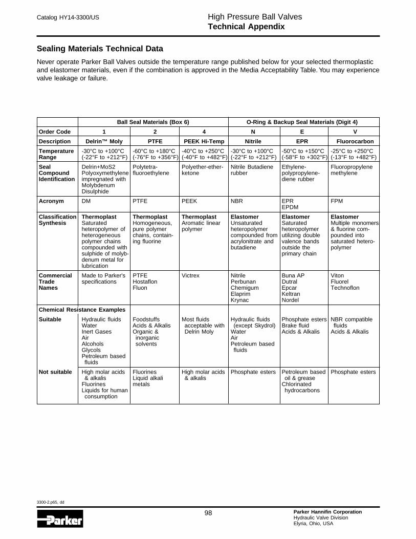
Catalog HY14-3300/US
3300-2.p65, dd
98 Parker Hannifin CorporationHydraulic Valve DivisionElyria, Ohio, USA
H
High Pressure Ball ValvesTechnical Appendix
Sealing Materials Technical Data
Never operate Parker Ball Valves outside the temperature range published below for your selected thermoplasticand elastomer materials, even if the combination is approved in the Media Acceptability Table. You may experiencevalve leakage or failure.
Ball Seal Materials (Box 6) O-Ring & Backup Seal Materials (Digit 4)
Order Code 1 2 4 N E V
Description Delrin™ Moly PTFE PEEK Hi-Temp Nitrile EPR Fluorocarbon
Temperature -30°C to +100°C -60°C to +180°C -40°C to +250°C -30°C to +100°C -50°C to +150°C -25°C to +250°CRange (-22°F to +212°F) (-76°F to +356°F) (-40°F to +482°F) (-22°F to +212°F) (-58°F to +302°F) (-13°F to +482°F)
Seal Delrin+MoS2 Polytetra- Polyether-ether- Nitrile Butadiene Ethylene- FluoropropyleneCompound Polyoxymethylene fluoroethylene ketone rubber polypropylene- methyleneIdentification impregnated with diene rubber
MolybdenumDisulphide
Acronym DM PTFE PEEK NBR EPR FPMEPDM
Classification Thermoplast Thermoplast Thermoplast Elastomer Elastomer ElastomerSynthesis Saturated Homogeneous, Aromatic linear Unsaturated Saturated Multiple monomers
heteropolymer of pure polymer polymer heteropolymer heteropolymer & fluorine com-heterogeneous chains, contain- compounded from utilizing double pounded intopolymer chains ing fluorine acrylonitrate and valence bands saturated hetero-compounded with butadiene outside the polymersulphide of molyb- primary chaindenum metal forlubrication
Commercial Made to Parker's PTFE Victrex Nitrile Buna AP VitonTrade specifications Hostaflon Perbunan Dutral FluorelNames Fluon Chemigum Epcar Technoflon
Elaprim KeltranKrynac Nordel
Chemical Resistance Examples
Suitable Hydraulic fluids Foodstuffs Most fluids Hydraulic fluids Phosphate esters NBR compatibleWater Acids & Alkalis acceptable with (except Skydrol) Brake fluid fluidsInert Gases Organic & Delrin Moly Water Acids & Alkalis Acids & AlkalisAir inorganic AirAlcohols solvents Petroleum basedGlycols fluidsPetroleum basedfluids
Not suitable High molar acids Fluorines High molar acids Phosphate esters Petroleum based Phosphate esters& alkalis Liquid alkali & alkalis oil & grease
Fluorines metals ChlorinatedLiquids for human hydrocarbonsconsumption

Catalog HY14-3300/US
3300-2.p65, dd
99 Parker Hannifin CorporationHydraulic Valve DivisionElyria, Ohio, USA
IntroductionFeatures & AdvantagesLow Pressure Ball Valves
The Parker Low Pressure Ball Valve Product Line serves in applicationsranging from 600 to 2,000 PSI.
� Packing Nut Stem � Seals leak by tightening
� PTFE Seals � High resistance to corrosion
� Full Optimum Flow � Maximum system efficiency
� Blow Out Proof Stem � Safety and reliability
� Brass, Carbon Steel, and � One ball valve sourceStainless Steel Bodies
Features Advantages
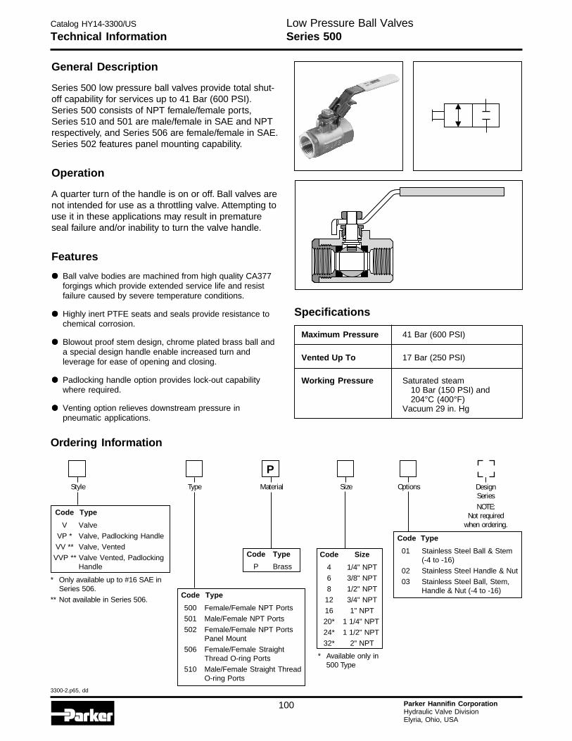
Catalog HY14-3300/US
3300-2.p65, dd
100 Parker Hannifin CorporationHydraulic Valve DivisionElyria, Ohio, USA
H
Low Pressure Ball ValvesTechnical Information Series 500
General Description
Series 500 low pressure ball valves provide total shut-off capability for services up to 41 Bar (600 PSI).Series 500 consists of NPT female/female ports,Series 510 and 501 are male/female in SAE and NPTrespectively, and Series 506 are female/female in SAE.Series 502 features panel mounting capability.
Operation
A quarter turn of the handle is on or off. Ball valves arenot intended for use as a throttling valve. Attempting touse it in these applications may result in prematureseal failure and/or inability to turn the valve handle.
Features
••••• Ball valve bodies are machined from high quality CA377forgings which provide extended service life and resistfailure caused by severe temperature conditions.
••••• Highly inert PTFE seats and seals provide resistance tochemical corrosion.
••••• Blowout proof stem design, chrome plated brass ball anda special design handle enable increased turn andleverage for ease of opening and closing.
••••• Padlocking handle option provides lock-out capabilitywhere required.
••••• Venting option relieves downstream pressure inpneumatic applications.
Specifications
Maximum Pressure 41 Bar (600 PSI)
Vented Up To 17 Bar (250 PSI)
Working Pressure Saturated steam10 Bar (150 PSI) and204°C (400°F)
Vacuum 29 in. Hg
Code Size
4 1/4" NPT
6 3/8" NPT
8 1/2" NPT
12 3/4" NPT
16 1" NPT
20* 1 1/4" NPT
24* 1 1/2" NPT
32* 2" NPT
* Available only in500 Type
Code Type
500 Female/Female NPT Ports
501 Male/Female NPT Ports
502 Female/Female NPT PortsPanel Mount
506 Female/Female StraightThread O-ring Ports
510 Male/Female Straight ThreadO-ring Ports
Code Type
01 Stainless Steel Ball & Stem(-4 to -16)
02 Stainless Steel Handle & Nut
03 Stainless Steel Ball, Stem,Handle & Nut (-4 to -16)
Code Type
V Valve
VP * Valve, Padlocking Handle
VV ** Valve, Vented
VVP ** Valve Vented, PadlockingHandle
Code Type
P Brass
DesignSeriesNOTE:
Not requiredwhen ordering.
Style OptionsType SizeMaterial
P
Ordering Information
* Only available up to #16 SAE inSeries 506.
** Not available in Series 506.
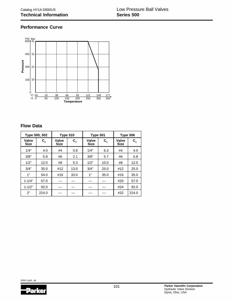
Catalog HY14-3300/US
3300-2.p65, dd
101 Parker Hannifin CorporationHydraulic Valve DivisionElyria, Ohio, USA
Low Pressure Ball ValvesTechnical Information Series 500
Performance Curve
177350
149300
121250
93200
66150
38100
10-18500
Temperature
°C°F
0
150 10
300 21
450
600PSI
31
41Bar
Pre
ssu
re
Type 500, 502 Type 510 Type 501 Type 506
Valve CV Valve CV Valve CV Valve CVSize Size Size Size
1/4" 4.0 #4 0.8 1/4" 6.3 #4 4.0
3/8" 5.8 #6 2.1 3/8" 5.7 #6 5.8
1/2" 12.0 #8 5.3 1/2" 10.0 #8 12.0
3/4" 35.0 #12 13.0 3/4" 25.0 #12 25.0
1" 54.0 #16 33.0 1" 35.0 #16 35.0
1-1/4" 57.0 — — — — #20 57.0
1-1/2" 92.0 — — — — #24 92.0
2" 224.0 — — — — #32 224.0
Flow Data
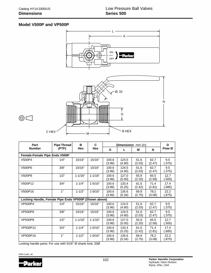
Catalog HY14-3300/US
3300-2.p65, dd
102 Parker Hannifin CorporationHydraulic Valve DivisionElyria, Ohio, USA
H
Low Pressure Ball ValvesDimensions Series 500
Part Pipe Thread B C Dimensions mm (in) DNumber (PTF) Hex Hex K L M N Flow Ø
Female-Female Pipe Ends V500PV500P4 1/4" 15/16" 15/16" 100.6 124.5 51.6 62.7 9.5
(3.96) (4.90) (2.03) (2.47) (.375)
V500P6 3/8" 15/16" 15/16" 100.6 124.5 51.6 62.7 9.5(3.96) (4.90) (2.03) (2.47) (.375)
V500P8 1/2" 1-1/16" 1-1/16" 100.6 127.0 55.9 65.5 12.7(3.96) (5.00) (2.20) (2.58) (.500)
V500P12 3/4" 1-1/4" 1-5/16" 100.6 133.4 61.5 71.4 17.4(3.96) (5.25) (2.42) (2.81) (.685)
V500P16 1" 1-1/2" 1-9/16" 100.6 135.6 69.9 78.2 22.2(3.96) (5.34) (2.75) (3.08) (.875)
Locking Handle, Female Pipe Ends VP500P (Shown above)VP500P4 1/4" 15/16" 15/16" 100.6 124.5 51.6 62.7 9.5
(3.96) (4.90) (2.03) (2.47) (.375)VP500P6 3/8" 15/16" 15/16" 100.6 124.5 51.6 62.7 9.5
(3.96) (4.90) (2.03) (2.47) (.375)
VP500P8 1/2" 1-1/16" 1-1/16" 100.6 127.0 55.9 65.5 12.7(3.96) (5.00) (2.20) (2.58) (.500)
VP500P12 3/4" 1-1/4" 1-5/16" 100.6 133.4 61.5 71.4 17.4(3.96) (5.25) (2.42) (2.81) (.685)
VP500P16 1" 1-1/2" 1-9/16" 100.6 135.6 69.9 78.2 22.2(3.96) (5.34) (2.75) (3.08) (.875)
Locking handle parts: For use with 5/16" Ø shank lock; 33Ø
Model V500P and VP500P
L
ON
OFF
N
Ø. 33
D
B HEXM
C HEX
K

Catalog HY14-3300/US
3300-2.p65, dd
103 Parker Hannifin CorporationHydraulic Valve DivisionElyria, Ohio, USA
Low Pressure Ball ValvesDimensions Series 500
Part Pipe B C Dimensions mm (in) DNumber Thread Hex Hex J K L M N Flow Ø
Vented, Female Pipe Ends VV500PVV500P4 1/4" 15/16" 15/16" 100.6 28.2 124.5 51.6 62.7 9.5
(3.96) (1.11) (4.90) (2.03) (2.47) (.375)
VV500P6 3/8" 15/16" 15/16" 100.6 28.2 124.5 51.6 62.7 9.5(3.96) (1.11) (4.90) (2.03) (2.47) (.375)
VV500P8 1/2" 1-1/16" 1-1/16" 100.6 31.2 127.0 55.9 65.5 12.7(3.96) (1.23) (5.00) (2.20) (2.58) (.500)
VV500P12 3/4" 1-1/4" 1-5/16" 100.6 36.8 133.4 61.5 71.4 17.4(3.96) (1.45) (5.25) (2.42) (2.81) (.685)
VV500P16 1" 1-1/2" 1-9/16" 100.6 40.1 135.6 69.9 78.2 22.2(3.96) (1.58) (5.34) (2.75) (3.08) (.875)
OSHA 29 CFR Part 1910 Vented, Locking Handle, Female Pipe Ends VVP500P (Shown above)VVP500P4 1/4" 15/16" 15/16" 100.6 28.2 124.5 51.6 62.7 9.5
(3.96) (1.11) (4.90) (2.03) (2.47) (.375)VVP500P6 3/8" 15/16" 15/16" 100.6 28.2 124.5 51.6 62.7 9.5
(3.96) (1.11) (4.90) (2.03) (2.47) (.375)
VVP500P8 1/2" 1-1/16" 1-1/16" 100.6 31.2 127.0 55.9 65.5 12.7(3.96) (1.23) (5.00) (2.20) (2.58) (.500)
VVP500P12 3/4" 1-1/4" 1-5/16" 100.6 36.8 133.4 61.5 71.4 17.4(3.96) (1.45) (5.25) (2.42) (2.81) (.685)
VVP500P16 1" 1-1/2" 1-9/16" 100.6 40.1 135.6 69.9 78.2 22.2(3.96) (1.58) (5.34) (2.75) (3.08) (.875)
Locking handle parts: For use with 5/16" Ø shank lock
L
J
ON
OFF
Ø. 33
B HEX
N
D
KM
C HEX10-32 UNF-2B(ALL SIZES)
Model VV500P and VVP500P
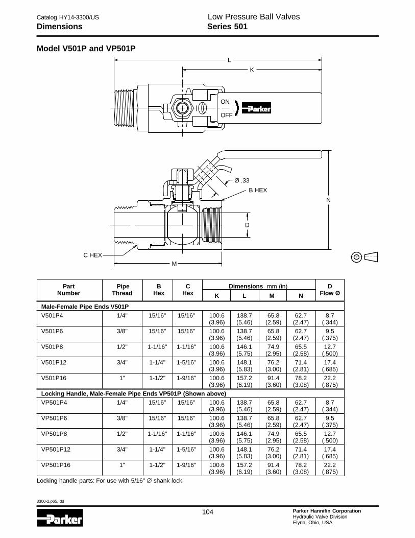
Catalog HY14-3300/US
3300-2.p65, dd
104 Parker Hannifin CorporationHydraulic Valve DivisionElyria, Ohio, USA
H
Low Pressure Ball ValvesDimensions Series 501
Part Pipe B C Dimensions mm (in) DNumber Thread Hex Hex K L M N Flow Ø
Male-Female Pipe Ends V501PV501P4 1/4" 15/16" 15/16" 100.6 138.7 65.8 62.7 8.7
(3.96) (5.46) (2.59) (2.47) (.344)V501P6 3/8" 15/16" 15/16" 100.6 138.7 65.8 62.7 9.5
(3.96) (5.46) (2.59) (2.47) (.375)
V501P8 1/2" 1-1/16" 1-1/16" 100.6 146.1 74.9 65.5 12.7(3.96) (5.75) (2.95) (2.58) (.500)
V501P12 3/4" 1-1/4" 1-5/16" 100.6 148.1 76.2 71.4 17.4(3.96) (5.83) (3.00) (2.81) (.685)
V501P16 1" 1-1/2" 1-9/16" 100.6 157.2 91.4 78.2 22.2(3.96) (6.19) (3.60) (3.08) (.875)
Locking Handle, Male-Female Pipe Ends VP501P (Shown above)VP501P4 1/4" 15/16" 15/16" 100.6 138.7 65.8 62.7 8.7
(3.96) (5.46) (2.59) (2.47) (.344)
VP501P6 3/8" 15/16" 15/16" 100.6 138.7 65.8 62.7 9.5(3.96) (5.46) (2.59) (2.47) (.375)
VP501P8 1/2" 1-1/16" 1-1/16" 100.6 146.1 74.9 65.5 12.7(3.96) (5.75) (2.95) (2.58) (.500)
VP501P12 3/4" 1-1/4" 1-5/16" 100.6 148.1 76.2 71.4 17.4(3.96) (5.83) (3.00) (2.81) (.685)
VP501P16 1" 1-1/2" 1-9/16" 100.6 157.2 91.4 78.2 22.2(3.96) (6.19) (3.60) (3.08) (.875)
Locking handle parts: For use with 5/16'’ ∅ shank lock
Model V501P and VP501P
ON
OFF
L
K
B HEX
Ø .33
D
MC HEX
N
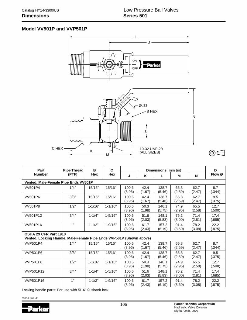
Catalog HY14-3300/US
3300-2.p65, dd
105 Parker Hannifin CorporationHydraulic Valve DivisionElyria, Ohio, USA
Low Pressure Ball ValvesDimensions Series 501
Part Pipe Thread B C Dimensions mm (in) DNumber (PTF) Hex Hex J K L M N Flow Ø
Vented, Male-Female Pipe Ends VV501PVV501P4 1/4" 15/16" 15/16" 100.6 42.4 138.7 65.8 62.7 8.7
(3.96) (1.67) (5.46) (2.59) (2.47) (.344)VV501P6 3/8" 15/16" 15/16" 100.6 42.4 138.7 65.8 62.7 9.5
(3.96) (1.67) (5.46) (2.59) (2.47) (.375)
VV501P8 1/2" 1-1/16" 1-1/16" 100.6 50.3 146.1 74.9 65.5 12.7(3.96) (1.98) (5.75) (2.95) (2.58) (.500)
VV501P12 3/4" 1-1/4" 1-5/16" 100.6 51.6 148.1 76.2 71.4 17.4(3.96) (2.03) (5.83) (3.00) (2.81) (.685)
VV501P16 1" 1-1/2" 1-9/16" 100.6 61.7 157.2 91.4 78.2 22.2(3.96) (2.43) (6.19) (3.60) (3.08) (.875)
OSHA 29 CFR Part 1910Vented, Locking Handle, Male-Female Pipe Ends VVP501P (Shown above)VVP501P4 1/4" 15/16" 15/16" 100.6 42.4 138.7 65.8 62.7 8.7
(3.96) (1.67) (5.46) (2.59) (2.47) (.344)
VVP501P6 3/8" 15/16" 15/16" 100.6 42.4 138.7 65.8 62.7 9.5(3.96) (1.67) (5.46) (2.59) (2.47) (.375)
VVP501P8 1/2" 1-1/16" 1-1/16" 100.6 50.3 146.1 74.9 65.5 12.7(3.96) (1.98) (5.75) (2.95) (2.58) (.500)
VVP501P12 3/4" 1-1/4" 1-5/16" 100.6 51.6 148.1 76.2 71.4 17.4(3.96) (2.03) (5.83) (3.00) (2.81) (.685)
VVP501P16 1" 1-1/2" 1-9/16" 100.6 61.7 157.2 91.4 78.2 22.2(3.96) (2.43) (6.19) (3.60) (3.08) (.875)
Locking handle parts: For use with 5/16'’ ∅ shank lock
L
J
ON
OFF
N
Ø. 33
B HEX
D
10-32 UNF-2B(ALL SIZES)
MK
C HEX
Model VV501P and VVP501P
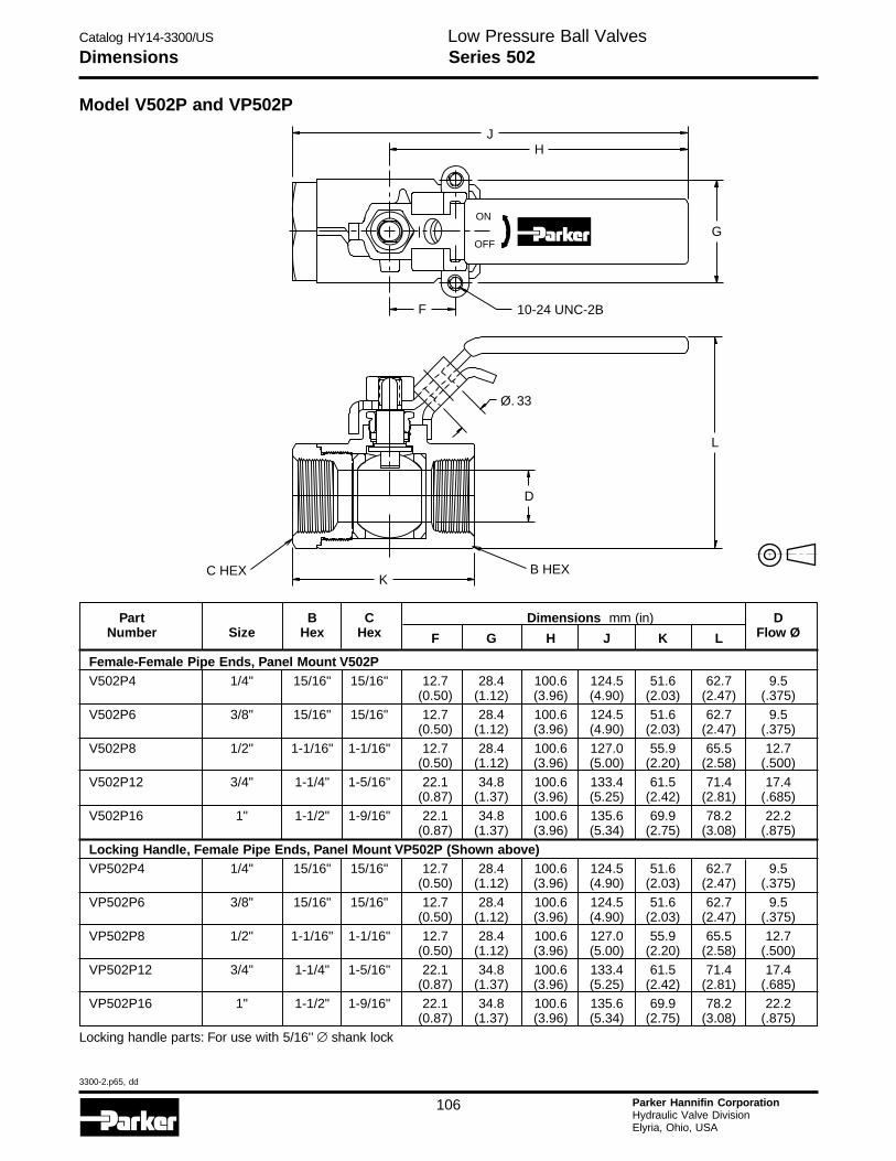
Catalog HY14-3300/US
3300-2.p65, dd
106 Parker Hannifin CorporationHydraulic Valve DivisionElyria, Ohio, USA
H
Low Pressure Ball ValvesSeries 502Dimensions
Part B C Dimensions mm (in) DNumber Size Hex Hex F G H J K L Flow Ø
Female-Female Pipe Ends, Panel Mount V502PV502P4 1/4" 15/16" 15/16" 12.7 28.4 100.6 124.5 51.6 62.7 9.5
(0.50) (1.12) (3.96) (4.90) (2.03) (2.47) (.375)V502P6 3/8" 15/16" 15/16" 12.7 28.4 100.6 124.5 51.6 62.7 9.5
(0.50) (1.12) (3.96) (4.90) (2.03) (2.47) (.375)
V502P8 1/2" 1-1/16" 1-1/16" 12.7 28.4 100.6 127.0 55.9 65.5 12.7(0.50) (1.12) (3.96) (5.00) (2.20) (2.58) (.500)
V502P12 3/4" 1-1/4" 1-5/16" 22.1 34.8 100.6 133.4 61.5 71.4 17.4(0.87) (1.37) (3.96) (5.25) (2.42) (2.81) (.685)
V502P16 1" 1-1/2" 1-9/16" 22.1 34.8 100.6 135.6 69.9 78.2 22.2(0.87) (1.37) (3.96) (5.34) (2.75) (3.08) (.875)
Locking Handle, Female Pipe Ends, Panel Mount VP502P (Shown above)VP502P4 1/4" 15/16" 15/16" 12.7 28.4 100.6 124.5 51.6 62.7 9.5
(0.50) (1.12) (3.96) (4.90) (2.03) (2.47) (.375)
VP502P6 3/8" 15/16" 15/16" 12.7 28.4 100.6 124.5 51.6 62.7 9.5(0.50) (1.12) (3.96) (4.90) (2.03) (2.47) (.375)
VP502P8 1/2" 1-1/16" 1-1/16" 12.7 28.4 100.6 127.0 55.9 65.5 12.7(0.50) (1.12) (3.96) (5.00) (2.20) (2.58) (.500)
VP502P12 3/4" 1-1/4" 1-5/16" 22.1 34.8 100.6 133.4 61.5 71.4 17.4(0.87) (1.37) (3.96) (5.25) (2.42) (2.81) (.685)
VP502P16 1" 1-1/2" 1-9/16" 22.1 34.8 100.6 135.6 69.9 78.2 22.2(0.87) (1.37) (3.96) (5.34) (2.75) (3.08) (.875)
Locking handle parts: For use with 5/16'’ ∅ shank lock
Model V502P and VP502P
JH
ON
OFFG
F 10-24 UNC-2B
L
Ø. 33
D
B HEXK
C HEX
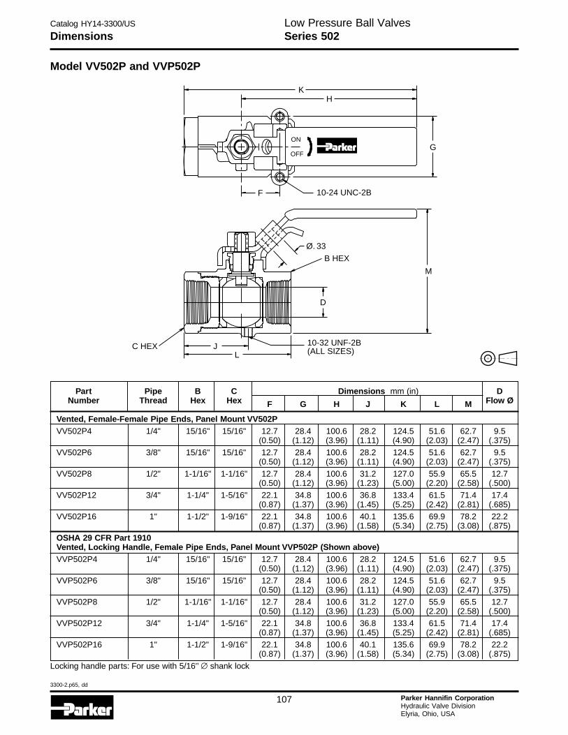
Catalog HY14-3300/US
3300-2.p65, dd
107 Parker Hannifin CorporationHydraulic Valve DivisionElyria, Ohio, USA
Low Pressure Ball ValvesSeries 502Dimensions
Part Pipe B C Dimensions mm (in) DNumber Thread Hex Hex F G H J K L M Flow Ø
Vented, Female-Female Pipe Ends, Panel Mount VV502PVV502P4 1/4" 15/16" 15/16" 12.7 28.4 100.6 28.2 124.5 51.6 62.7 9.5
(0.50) (1.12) (3.96) (1.11) (4.90) (2.03) (2.47) (.375)
VV502P6 3/8" 15/16" 15/16" 12.7 28.4 100.6 28.2 124.5 51.6 62.7 9.5(0.50) (1.12) (3.96) (1.11) (4.90) (2.03) (2.47) (.375)
VV502P8 1/2" 1-1/16" 1-1/16" 12.7 28.4 100.6 31.2 127.0 55.9 65.5 12.7(0.50) (1.12) (3.96) (1.23) (5.00) (2.20) (2.58) (.500)
VV502P12 3/4" 1-1/4" 1-5/16" 22.1 34.8 100.6 36.8 133.4 61.5 71.4 17.4(0.87) (1.37) (3.96) (1.45) (5.25) (2.42) (2.81) (.685)
VV502P16 1" 1-1/2" 1-9/16" 22.1 34.8 100.6 40.1 135.6 69.9 78.2 22.2(0.87) (1.37) (3.96) (1.58) (5.34) (2.75) (3.08) (.875)
OSHA 29 CFR Part 1910Vented, Locking Handle, Female Pipe Ends, Panel Mount VVP502P (Shown above)VVP502P4 1/4" 15/16" 15/16" 12.7 28.4 100.6 28.2 124.5 51.6 62.7 9.5
(0.50) (1.12) (3.96) (1.11) (4.90) (2.03) (2.47) (.375)VVP502P6 3/8" 15/16" 15/16" 12.7 28.4 100.6 28.2 124.5 51.6 62.7 9.5
(0.50) (1.12) (3.96) (1.11) (4.90) (2.03) (2.47) (.375)
VVP502P8 1/2" 1-1/16" 1-1/16" 12.7 28.4 100.6 31.2 127.0 55.9 65.5 12.7(0.50) (1.12) (3.96) (1.23) (5.00) (2.20) (2.58) (.500)
VVP502P12 3/4" 1-1/4" 1-5/16" 22.1 34.8 100.6 36.8 133.4 61.5 71.4 17.4(0.87) (1.37) (3.96) (1.45) (5.25) (2.42) (2.81) (.685)
VVP502P16 1" 1-1/2" 1-9/16" 22.1 34.8 100.6 40.1 135.6 69.9 78.2 22.2(0.87) (1.37) (3.96) (1.58) (5.34) (2.75) (3.08) (.875)
Locking handle parts: For use with 5/16'’ ∅ shank lock
Model VV502P and VVP502P
KH
G
10-24 UNC-2B
ON
OFF
F
Ø. 33
B HEX
M
D
C HEX JL
10-32 UNF-2B(ALL SIZES)
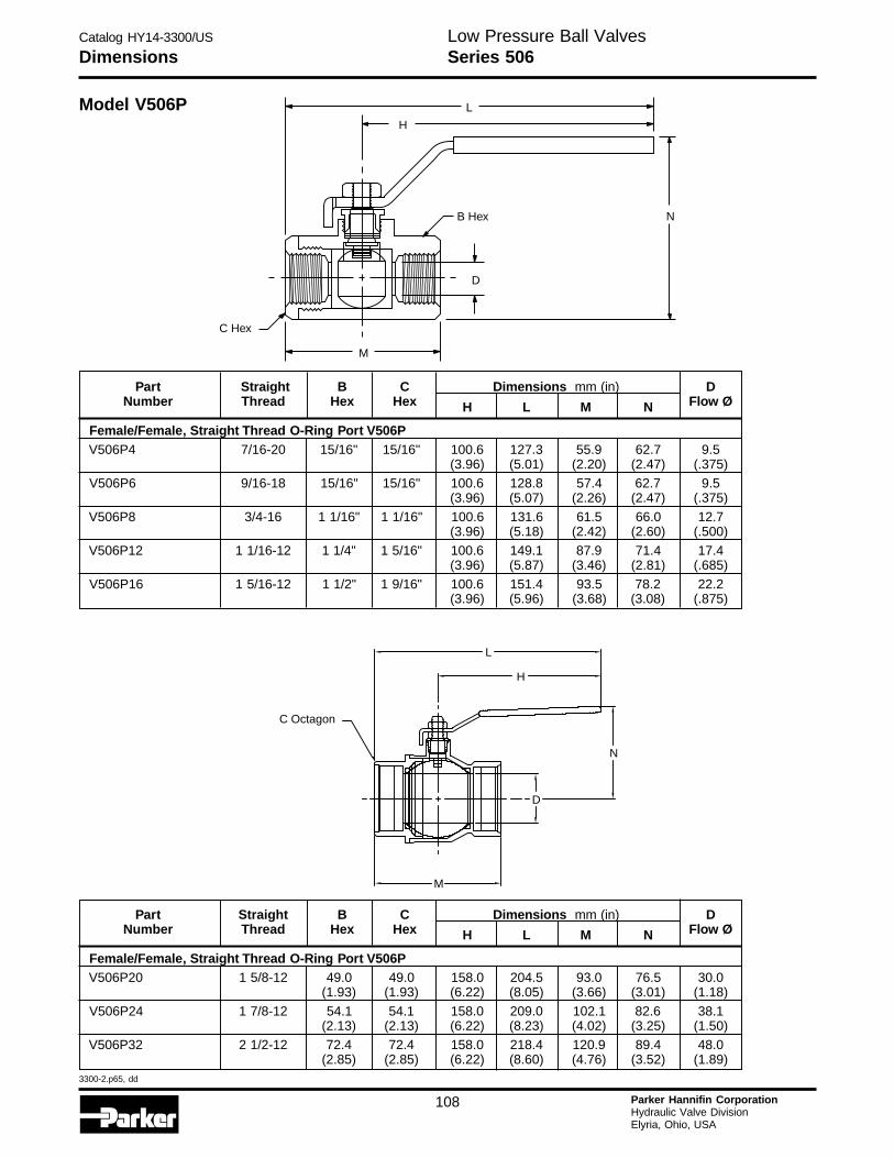
Catalog HY14-3300/US
3300-2.p65, dd
108 Parker Hannifin CorporationHydraulic Valve DivisionElyria, Ohio, USA
H
Series 506Dimensions
Model V506P L
N
H
B Hex
D
C Hex
M
C Octagon
N
D
M
L
H
Part Straight B C Dimensions mm (in) DNumber Thread Hex Hex H L M N Flow Ø
Female/Female, Straight Thread O-Ring Port V506PV506P4 7/16-20 15/16" 15/16" 100.6 127.3 55.9 62.7 9.5
(3.96) (5.01) (2.20) (2.47) (.375)V506P6 9/16-18 15/16" 15/16" 100.6 128.8 57.4 62.7 9.5
(3.96) (5.07) (2.26) (2.47) (.375)
V506P8 3/4-16 1 1/16" 1 1/16" 100.6 131.6 61.5 66.0 12.7(3.96) (5.18) (2.42) (2.60) (.500)
V506P12 1 1/16-12 1 1/4" 1 5/16" 100.6 149.1 87.9 71.4 17.4(3.96) (5.87) (3.46) (2.81) (.685)
V506P16 1 5/16-12 1 1/2" 1 9/16" 100.6 151.4 93.5 78.2 22.2(3.96) (5.96) (3.68) (3.08) (.875)
Part Straight B C Dimensions mm (in) DNumber Thread Hex Hex H L M N Flow Ø
Female/Female, Straight Thread O-Ring Port V506PV506P20 1 5/8-12 49.0 49.0 158.0 204.5 93.0 76.5 30.0
(1.93) (1.93) (6.22) (8.05) (3.66) (3.01) (1.18)
V506P24 1 7/8-12 54.1 54.1 158.0 209.0 102.1 82.6 38.1(2.13) (2.13) (6.22) (8.23) (4.02) (3.25) (1.50)
V506P32 2 1/2-12 72.4 72.4 158.0 218.4 120.9 89.4 48.0(2.85) (2.85) (6.22) (8.60) (4.76) (3.52) (1.89)
Low Pressure Ball Valves
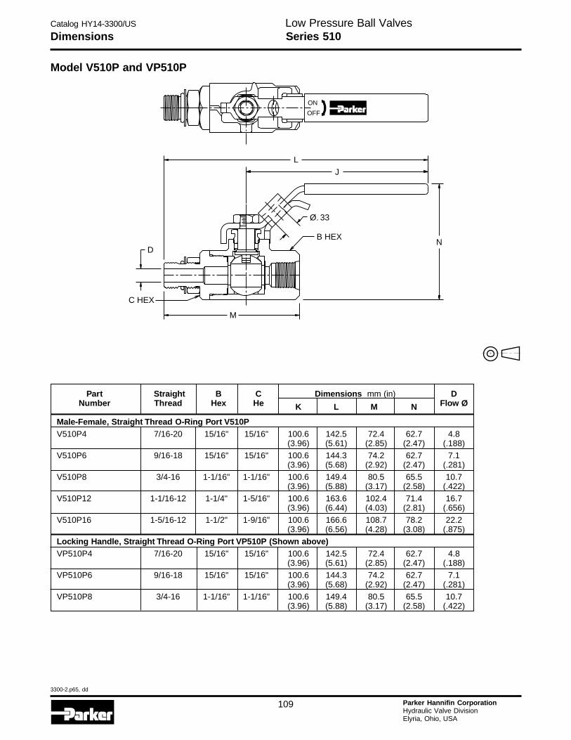
Catalog HY14-3300/US
3300-2.p65, dd
109 Parker Hannifin CorporationHydraulic Valve DivisionElyria, Ohio, USA
Series 510DimensionsLow Pressure Ball Valves
Model V510P and VP510P
ON
OFF
L
J
N
Ø. 33
B HEX
M
D
C HEX
Part Straight B C Dimensions mm (in) DNumber Thread Hex He K L M N Flow Ø
Male-Female, Straight Thread O-Ring Port V510PV510P4 7/16-20 15/16" 15/16" 100.6 142.5 72.4 62.7 4.8
(3.96) (5.61) (2.85) (2.47) (.188)V510P6 9/16-18 15/16" 15/16" 100.6 144.3 74.2 62.7 7.1
(3.96) (5.68) (2.92) (2.47) (.281)
V510P8 3/4-16 1-1/16" 1-1/16" 100.6 149.4 80.5 65.5 10.7(3.96) (5.88) (3.17) (2.58) (.422)
V510P12 1-1/16-12 1-1/4" 1-5/16" 100.6 163.6 102.4 71.4 16.7(3.96) (6.44) (4.03) (2.81) (.656)
V510P16 1-5/16-12 1-1/2" 1-9/16" 100.6 166.6 108.7 78.2 22.2(3.96) (6.56) (4.28) (3.08) (.875)
Locking Handle, Straight Thread O-Ring Port VP510P (Shown above)VP510P4 7/16-20 15/16" 15/16" 100.6 142.5 72.4 62.7 4.8
(3.96) (5.61) (2.85) (2.47) (.188)
VP510P6 9/16-18 15/16" 15/16" 100.6 144.3 74.2 62.7 7.1(3.96) (5.68) (2.92) (2.47) (.281)
VP510P8 3/4-16 1-1/16" 1-1/16" 100.6 149.4 80.5 65.5 10.7(3.96) (5.88) (3.17) (2.58) (.422)
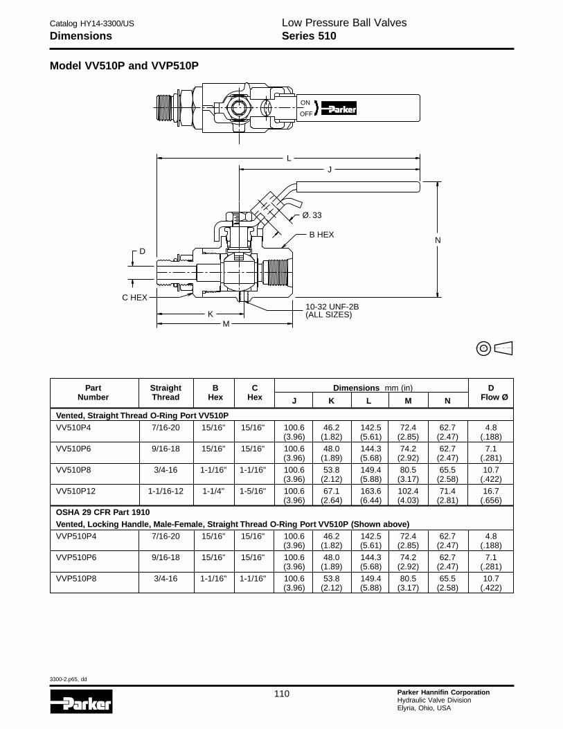
Catalog HY14-3300/US
3300-2.p65, dd
110 Parker Hannifin CorporationHydraulic Valve DivisionElyria, Ohio, USA
H
Series 510DimensionsLow Pressure Ball Valves
Model VV510P and VVP510P
D
C HEX
KM
10-32 UNF-2B(ALL SIZES)
Ø. 33
B HEXN
LJ
ON
OFF
Part Straight B C Dimensions mm (in) DNumber Thread Hex Hex J K L M N Flow Ø
Vented, Straight Thread O-Ring Port VV510PVV510P4 7/16-20 15/16" 15/16" 100.6 46.2 142.5 72.4 62.7 4.8
(3.96) (1.82) (5.61) (2.85) (2.47) (.188)VV510P6 9/16-18 15/16" 15/16" 100.6 48.0 144.3 74.2 62.7 7.1
(3.96) (1.89) (5.68) (2.92) (2.47) (.281)
VV510P8 3/4-16 1-1/16" 1-1/16" 100.6 53.8 149.4 80.5 65.5 10.7(3.96) (2.12) (5.88) (3.17) (2.58) (.422)
VV510P12 1-1/16-12 1-1/4" 1-5/16" 100.6 67.1 163.6 102.4 71.4 16.7(3.96) (2.64) (6.44) (4.03) (2.81) (.656)
OSHA 29 CFR Part 1910Vented, Locking Handle, Male-Female, Straight Thread O-Ring Port VV510P (Shown above)VVP510P4 7/16-20 15/16" 15/16" 100.6 46.2 142.5 72.4 62.7 4.8
(3.96) (1.82) (5.61) (2.85) (2.47) (.188)
VVP510P6 9/16-18 15/16" 15/16" 100.6 48.0 144.3 74.2 62.7 7.1(3.96) (1.89) (5.68) (2.92) (2.47) (.281)
VVP510P8 3/4-16 1-1/16" 1-1/16" 100.6 53.8 149.4 80.5 65.5 10.7(3.96) (2.12) (5.88) (3.17) (2.58) (.422)
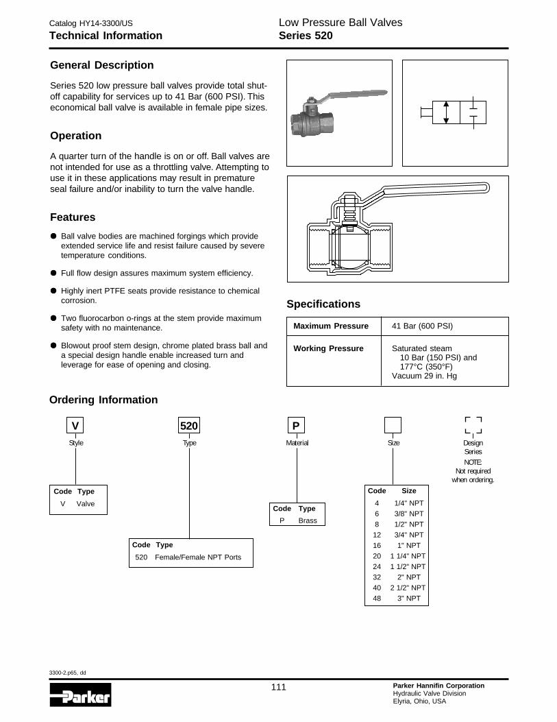
Catalog HY14-3300/US
3300-2.p65, dd
111 Parker Hannifin CorporationHydraulic Valve DivisionElyria, Ohio, USA
Low Pressure Ball ValvesTechnical Information Series 520
General Description
Series 520 low pressure ball valves provide total shut-off capability for services up to 41 Bar (600 PSI). Thiseconomical ball valve is available in female pipe sizes.
Operation
A quarter turn of the handle is on or off. Ball valves arenot intended for use as a throttling valve. Attempting touse it in these applications may result in prematureseal failure and/or inability to turn the valve handle.
Features
••••• Ball valve bodies are machined forgings which provideextended service life and resist failure caused by severetemperature conditions.
••••• Full flow design assures maximum system efficiency.
••••• Highly inert PTFE seats provide resistance to chemicalcorrosion.
••••• Two fluorocarbon o-rings at the stem provide maximumsafety with no maintenance.
••••• Blowout proof stem design, chrome plated brass ball anda special design handle enable increased turn andleverage for ease of opening and closing.
Specifications
Maximum Pressure 41 Bar (600 PSI)
Working Pressure Saturated steam10 Bar (150 PSI) and177°C (350°F)
Vacuum 29 in. Hg
Code Size
4 1/4" NPT
6 3/8" NPT
8 1/2" NPT
12 3/4" NPT
16 1" NPT
20 1 1/4" NPT
24 1 1/2" NPT
32 2" NPT
40 2 1/2" NPT
48 3" NPT
Code Type
520 Female/Female NPT Ports
Code Type
V ValveCode Type
P Brass
DesignSeriesNOTE:
Not requiredwhen ordering.
Style Type SizeMaterial
P
Ordering Information
V 520
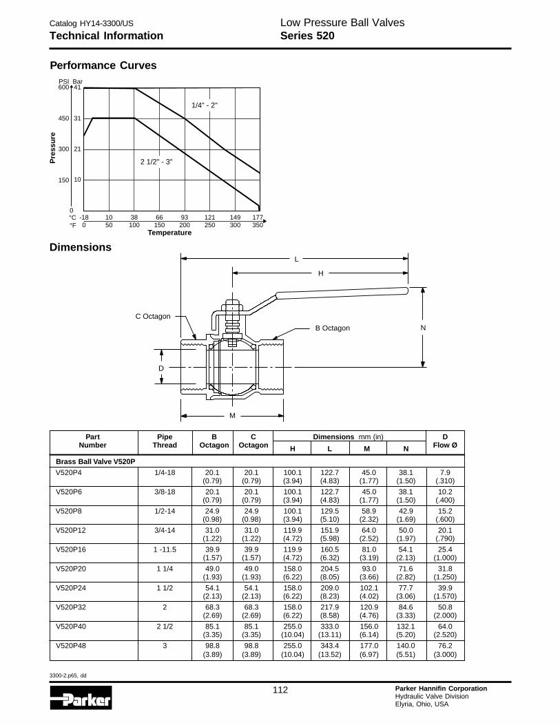
Catalog HY14-3300/US
3300-2.p65, dd
112 Parker Hannifin CorporationHydraulic Valve DivisionElyria, Ohio, USA
H
Performance Curves
Technical Information Series 520Low Pressure Ball Valves
Part Pipe B C Dimensions mm (in) DNumber Thread Octagon Octagon H L M N Flow Ø
Brass Ball Valve V520P
V520P4 1/4-18 20.1 20.1 100.1 122.7 45.0 38.1 7.9(0.79) (0.79) (3.94) (4.83) (1.77) (1.50) (.310)
V520P6 3/8-18 20.1 20.1 100.1 122.7 45.0 38.1 10.2(0.79) (0.79) (3.94) (4.83) (1.77) (1.50) (.400)
V520P8 1/2-14 24.9 24.9 100.1 129.5 58.9 42.9 15.2(0.98) (0.98) (3.94) (5.10) (2.32) (1.69) (.600)
V520P12 3/4-14 31.0 31.0 119.9 151.9 64.0 50.0 20.1(1.22) (1.22) (4.72) (5.98) (2.52) (1.97) (.790)
V520P16 1 -11.5 39.9 39.9 119.9 160.5 81.0 54.1 25.4(1.57) (1.57) (4.72) (6.32) (3.19) (2.13) (1.000)
V520P20 1 1/4 49.0 49.0 158.0 204.5 93.0 71.6 31.8(1.93) (1.93) (6.22) (8.05) (3.66) (2.82) (1.250)
V520P24 1 1/2 54.1 54.1 158.0 209.0 102.1 77.7 39.9(2.13) (2.13) (6.22) (8.23) (4.02) (3.06) (1.570)
V520P32 2 68.3 68.3 158.0 217.9 120.9 84.6 50.8(2.69) (2.69) (6.22) (8.58) (4.76) (3.33) (2.000)
V520P40 2 1/2 85.1 85.1 255.0 333.0 156.0 132.1 64.0(3.35) (3.35) (10.04) (13.11) (6.14) (5.20) (2.520)
V520P48 3 98.8 98.8 255.0 343.4 177.0 140.0 76.2(3.89) (3.89) (10.04) (13.52) (6.97) (5.51) (3.000)
C Octagon
B Octagon
H
N
M
D
L
Dimensions
177350
149300
121250
93200
66150
38100
10-18500
Temperature
°C°F
0
150 10
300 21
450
600PSI
31
41Bar
Pre
ssu
re
1/4" - 2"
2 1/2" - 3"
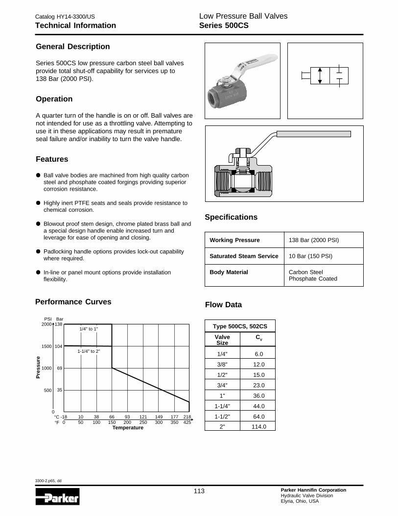
Catalog HY14-3300/US
3300-2.p65, dd
113 Parker Hannifin CorporationHydraulic Valve DivisionElyria, Ohio, USA
Technical Information Series 500CSLow Pressure Ball Valves
General Description
Series 500CS low pressure carbon steel ball valvesprovide total shut-off capability for services up to138 Bar (2000 PSI).
Operation
A quarter turn of the handle is on or off. Ball valves arenot intended for use as a throttling valve. Attempting touse it in these applications may result in prematureseal failure and/or inability to turn the valve handle.
Features
••••• Ball valve bodies are machined from high quality carbonsteel and phosphate coated forgings providing superiorcorrosion resistance.
••••• Highly inert PTFE seats and seals provide resistance tochemical corrosion.
••••• Blowout proof stem design, chrome plated brass ball anda special design handle enable increased turn andleverage for ease of opening and closing.
••••• Padlocking handle options provides lock-out capabilitywhere required.
••••• In-line or panel mount options provide installationflexibility.
Specifications
Performance Curves
177 218350 425
149300
121250
93200
66150
38100
10-18500
Temperature
°C°F
0
500 35
1000 69
1500
2000PSI
104
138Bar
Pre
ssu
re
1/4" to 1"
1-1/4" to 2"
Flow Data
Working Pressure 138 Bar (2000 PSI)
Saturated Steam Service 10 Bar (150 PSI)
Body Material Carbon SteelPhosphate Coated
Type 500CS, 502CS
Valve CVSize
1/4" 6.0
3/8" 12.0
1/2" 15.0
3/4" 23.0
1" 36.0
1-1/4" 44.0
1-1/2" 64.0
2" 114.0
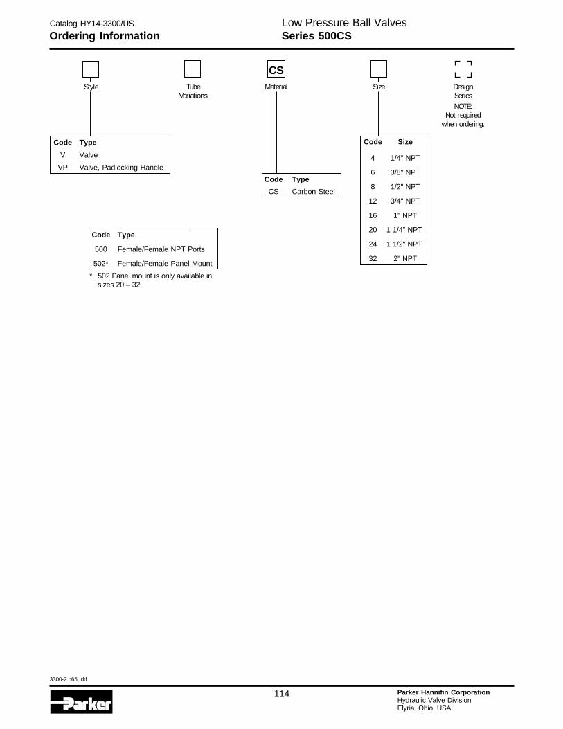
Catalog HY14-3300/US
3300-2.p65, dd
114 Parker Hannifin CorporationHydraulic Valve DivisionElyria, Ohio, USA
H
Ordering Information Series 500CSLow Pressure Ball Valves
Code Size
4 1/4" NPT
6 3/8" NPT
8 1/2" NPT
12 3/4" NPT
16 1" NPT
20 1 1/4" NPT
24 1 1/2" NPT
32 2" NPT
Code Type
500 Female/Female NPT Ports
502* Female/Female Panel Mount
CS
Code Type
V Valve
VP Valve, Padlocking Handle
Code Type
CS Carbon Steel
* 502 Panel mount is only available insizes 20 – 32.
TubeVariations
Material SizeStyle DesignSeriesNOTE:
Not requiredwhen ordering.
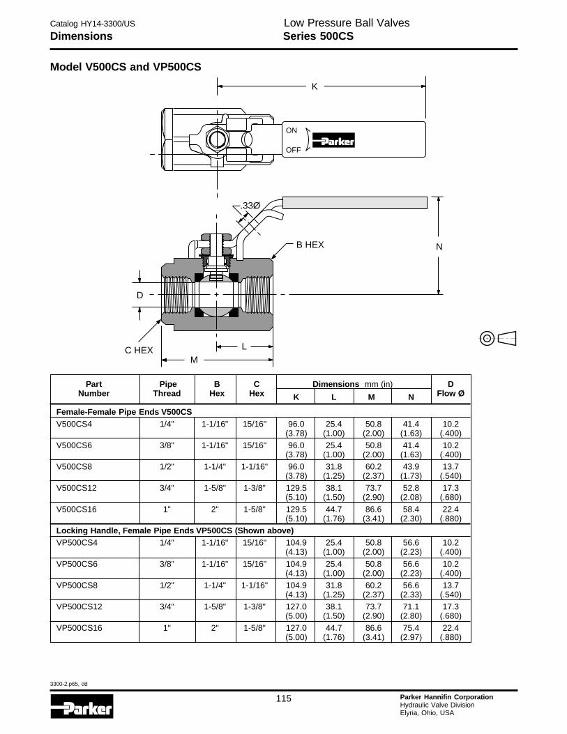
Catalog HY14-3300/US
3300-2.p65, dd
115 Parker Hannifin CorporationHydraulic Valve DivisionElyria, Ohio, USA
Dimensions Series 500CSLow Pressure Ball Valves
Model V500CS and VP500CS
Part Pipe B C Dimensions mm (in) DNumber Thread Hex Hex K L M N Flow Ø
Female-Female Pipe Ends V500CSV500CS4 1/4" 1-1/16" 15/16" 96.0 25.4 50.8 41.4 10.2
(3.78) (1.00) (2.00) (1.63) (.400)V500CS6 3/8" 1-1/16" 15/16" 96.0 25.4 50.8 41.4 10.2
(3.78) (1.00) (2.00) (1.63) (.400)
V500CS8 1/2" 1-1/4" 1-1/16" 96.0 31.8 60.2 43.9 13.7(3.78) (1.25) (2.37) (1.73) (.540)
V500CS12 3/4" 1-5/8" 1-3/8" 129.5 38.1 73.7 52.8 17.3(5.10) (1.50) (2.90) (2.08) (.680)
V500CS16 1" 2" 1-5/8" 129.5 44.7 86.6 58.4 22.4(5.10) (1.76) (3.41) (2.30) (.880)
Locking Handle, Female Pipe Ends VP500CS (Shown above)VP500CS4 1/4" 1-1/16" 15/16" 104.9 25.4 50.8 56.6 10.2
(4.13) (1.00) (2.00) (2.23) (.400)
VP500CS6 3/8" 1-1/16" 15/16" 104.9 25.4 50.8 56.6 10.2(4.13) (1.00) (2.00) (2.23) (.400)
VP500CS8 1/2" 1-1/4" 1-1/16" 104.9 31.8 60.2 56.6 13.7(4.13) (1.25) (2.37) (2.33) (.540)
VP500CS12 3/4" 1-5/8" 1-3/8" 127.0 38.1 73.7 71.1 17.3(5.00) (1.50) (2.90) (2.80) (.680)
VP500CS16 1" 2" 1-5/8" 127.0 44.7 86.6 75.4 22.4(5.00) (1.76) (3.41) (2.97) (.880)
ON
OFF
K
D
MLC HEX
B HEX N
.33Ø
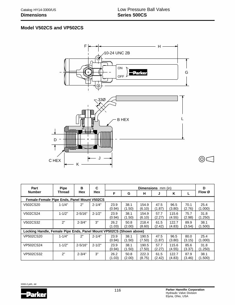
Catalog HY14-3300/US
3300-2.p65, dd
116 Parker Hannifin CorporationHydraulic Valve DivisionElyria, Ohio, USA
H
Dimensions Series 500CSLow Pressure Ball Valves
Model V502CS and VP502CS
Part Pipe B C Dimensions mm (in) DNumber Thread Hex Hex F G H J K L Flow Ø
Female-Female Pipe Ends, Panel Mount V502CSV502CS20 1-1/4" 2" 2-1/4" 23.9 38.1 154.9 47.5 96.5 70.1 25.4
(0.94) (1.50) (6.10) (1.87) (3.80) (2.76) (1.000)
V502CS24 1-1/2" 2-5/16" 2-1/2" 23.9 38.1 154.9 57.7 115.6 75.7 31.8(0.94) (1.50) (6.10) (2.27) (4.55) (2.98) (1.250)
V502CS32 2" 2-3/4" 3" 26.2 50.8 218.4 61.5 122.7 89.9 38.1(1.03) (2.00) (8.60) (2.42) (4.83) (3.54) (1.500)
Locking Handle, Female Pipe Ends, Panel Mount VP502CS (Shown above)VP502CS20 1-1/4" 2" 2-1/4" 23.9 38.1 190.5 47.5 96.5 80.0 25.4
(0.94) (1.50) (7.50) (1.87) (3.80) (3.15) (1.000)VP502CS24 1-1/2" 2-5/16" 2-1/2" 23.9 38.1 190.5 57.7 115.6 85.6 31.8
(0.94) (1.50) (7.50) (2.27) (4.55) (3.37) (1.250)
VP502CS32 2" 2-3/4" 3" 26.2 50.8 222.3 61.5 122.7 87.9 38.1(1.03) (2.00) (8.75) (2.42) (4.83) (3.46) (1.500)
ON
OFFG
F H
10-24 UNC 2B
D
K
JC HEX
B HEX L
.33Ø
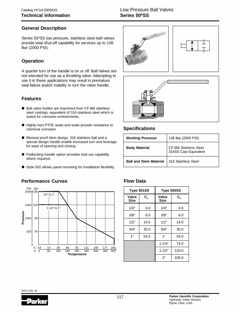
Catalog HY14-3300/US
3300-2.p65, dd
117 Parker Hannifin CorporationHydraulic Valve DivisionElyria, Ohio, USA
Performance Curves
177 204350 400
149300
121250
93200
66150
38100
10-18500
Temperature
°C°F
0
500 35
1000 69
1500
2000PSI
104
138Bar
Pre
ssu
re
1/4" to 1"
1-1/4" to 2"
Type 501SS Type 502SS
Valve CV Valve CVSize Size
1/4" 4.0 1/4" 4.0
3/8" 6.0 3/8" 6.0
1/2" 14.0 1/2" 14.0
3/4" 35.0 3/4" 35.0
1" 54.0 1" 54.0
1-1/4" 74.0
1-1/2" 120.0
2" 226.0
Flow Data
Technical Information Series 50*SSLow Pressure Ball Valves
General Description
Series 50*SS low pressure, stainless steel ball valvesprovide total shut-off capability for services up to 138Bar (2000 PSI).
Operation
A quarter turn of the handle is on or off. Ball Valves arenot intended for use as a throttling valve. Attempting touse it in these applications may result in prematureseal failure and/or inability to turn the valve handle.
Features
••••• Ball valve bodies are machined from CF-8M stainlesssteel castings, equivalent of 316 stainless steel which issuited for corrosive environments.
••••• Highly inert PTFE seats and seals provide resistance tochemical corrosion.
••••• Blowout proof stem design, 316 stainless ball and aspecial design handle enable increased turn and leveragefor ease of opening and closing.
••••• Padlocking handle option provides lock-out capabilitywhere required.
••••• Style 502 allows panel mounting for installation flexibility.
Specifications
Working Pressure 138 Bar (2000 PSI)
Body Material CF-8M Stainless Steel316SS Cast Equivalent
Ball and Stem Material 316 Stainless Steel
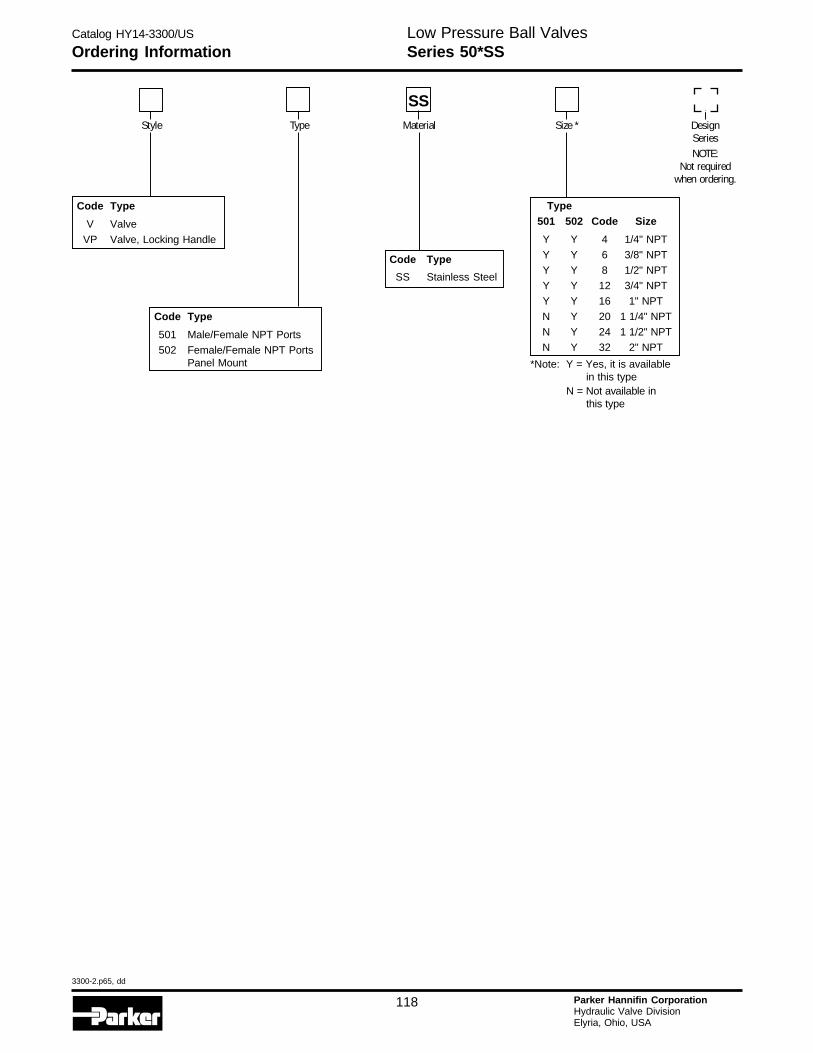
Catalog HY14-3300/US
3300-2.p65, dd
118 Parker Hannifin CorporationHydraulic Valve DivisionElyria, Ohio, USA
H
Low Pressure Ball ValvesSeries 50*SSOrdering Information
Type501 502 Code Size
Y Y 4 1/4" NPT
Y Y 6 3/8" NPT
Y Y 8 1/2" NPT
Y Y 12 3/4" NPT
Y Y 16 1" NPT
N Y 20 1 1/4" NPT
N Y 24 1 1/2" NPT
N Y 32 2" NPT
*Note: Y = Yes, it is availablein this type
N = Not available inthis type
Code Type
501 Male/Female NPT Ports
502 Female/Female NPT PortsPanel Mount
SS
Code Type
V Valve
VP Valve, Locking Handle
Code Type
SS Stainless Steel
DesignSeriesNOTE:
Not requiredwhen ordering.
Type Material Size *Style
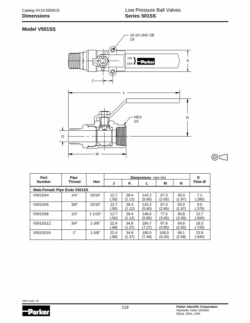
Catalog HY14-3300/US
3300-2.p65, dd
119 Parker Hannifin CorporationHydraulic Valve DivisionElyria, Ohio, USA
Dimensions Series 501SSLow Pressure Ball Valves
Model V501SS
Part Pipe Dimensions mm (in) DNumber Thread Hex J K L M N Flow Ø
Male-Female Pipe Ends V501SSV501SS4 1/4" 15/16" 12.7 28.4 142.2 67.3 50.0 7.1
(.50) (1.12) (5.60) (2.65) (1.97) (.280)V501SS6 3/8" 15/16" 12.7 28.4 142.2 67.3 50.0 9.5
(.50) (1.12) (5.60) (2.65) (1.97) (.375)
V501SS8 1/2" 1-1/16" 12.7 28.4 148.6 77.5 50.8 12.7(.50) (1.12) (5.85) (3.05) (2.00) (.500)
V501SS12 3/4" 1-3/8" 22.4 34.8 184.7 97.8 64.8 18.3(.88) (1.37) (7.27) (3.85) (2.55) (.720)
V501SS16 1" 1-5/8" 22.4 34.8 190.0 108.0 68.1 23.9(.88) (1.37) (7.48) (4.25) (2.68) (.940)
10-24 UNC-2B2X
ON
OFFK
J
L
NHEX2X
D
M
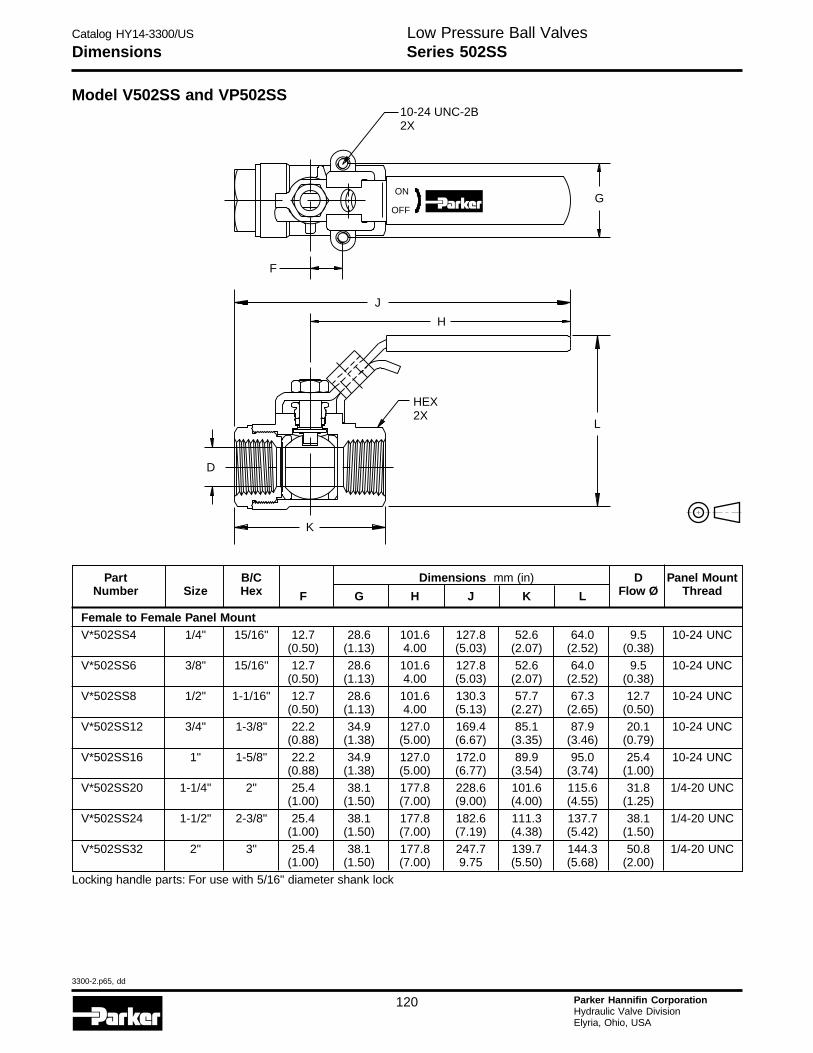
Catalog HY14-3300/US
3300-2.p65, dd
120 Parker Hannifin CorporationHydraulic Valve DivisionElyria, Ohio, USA
H
Dimensions Series 502SSLow Pressure Ball Valves
Model V502SS and VP502SS
K
D
HEX2X
L
H
J
F
G
10-24 UNC-2B2X
ON
OFF
Part B/C Dimensions mm (in) D Panel MountNumber Size Hex F G H J K L Flow Ø Thread
Female to Female Panel MountV*502SS4 1/4" 15/16" 12.7 28.6 101.6 127.8 52.6 64.0 9.5 10-24 UNC
(0.50) (1.13) 4.00 (5.03) (2.07) (2.52) (0.38)
V*502SS6 3/8" 15/16" 12.7 28.6 101.6 127.8 52.6 64.0 9.5 10-24 UNC(0.50) (1.13) 4.00 (5.03) (2.07) (2.52) (0.38)
V*502SS8 1/2" 1-1/16" 12.7 28.6 101.6 130.3 57.7 67.3 12.7 10-24 UNC(0.50) (1.13) 4.00 (5.13) (2.27) (2.65) (0.50)
V*502SS12 3/4" 1-3/8" 22.2 34.9 127.0 169.4 85.1 87.9 20.1 10-24 UNC(0.88) (1.38) (5.00) (6.67) (3.35) (3.46) (0.79)
V*502SS16 1" 1-5/8" 22.2 34.9 127.0 172.0 89.9 95.0 25.4 10-24 UNC(0.88) (1.38) (5.00) (6.77) (3.54) (3.74) (1.00)
V*502SS20 1-1/4" 2" 25.4 38.1 177.8 228.6 101.6 115.6 31.8 1/4-20 UNC(1.00) (1.50) (7.00) (9.00) (4.00) (4.55) (1.25)
V*502SS24 1-1/2" 2-3/8" 25.4 38.1 177.8 182.6 111.3 137.7 38.1 1/4-20 UNC(1.00) (1.50) (7.00) (7.19) (4.38) (5.42) (1.50)
V*502SS32 2" 3" 25.4 38.1 177.8 247.7 139.7 144.3 50.8 1/4-20 UNC(1.00) (1.50) (7.00) 9.75 (5.50) (5.68) (2.00)
Locking handle parts: For use with 5/16" diameter shank lock
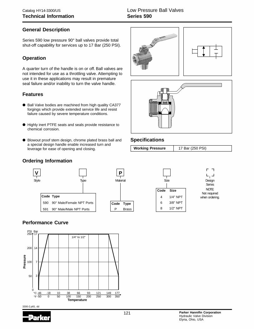
Catalog HY14-3300/US
3300-2.p65, dd
121 Parker Hannifin CorporationHydraulic Valve DivisionElyria, Ohio, USA
Technical Information Series 590Low Pressure Ball Valves
General Description
Series 590 low pressure 90° ball valves provide totalshut-off capability for services up to 17 Bar (250 PSI).
Operation
A quarter turn of the handle is on or off. Ball valves arenot intended for use as a throttling valve. Attempting touse it in these applications may result in prematureseal failure and/or inability to turn the valve handle.
Specifications
Working Pressure 17 Bar (250 PSI)
Features
••••• Ball Valve bodies are machined from high quality CA377forgings which provide extended service life and resistfailure caused by severe temperature conditions.
••••• Highly inert PTFE seats and seals provide resistance tochemical corrosion.
••••• Blowout proof stem design, chrome plated brass ball anda special design handle enable increased turn andleverage for ease of opening and closing.
V
Code Size
4 1/4" NPT
6 3/8" NPT
8 1/2" NPT
P
Code Type
P Brass
Code Type
590 90° Male/Female NPT Ports
591 90° Male/Male NPT Ports
Ordering Information
DesignSeriesNOTE:
Not requiredwhen ordering.
Type Material SizeStyle
Performance Curve
177350
149300
121250
93200
66150
10 3850 100
-18-460-50
Temperature
°C°F
0
50 3
100 7
200
250PSI
14
17Bar
Pre
ssur
e
1/4" to 1/2"
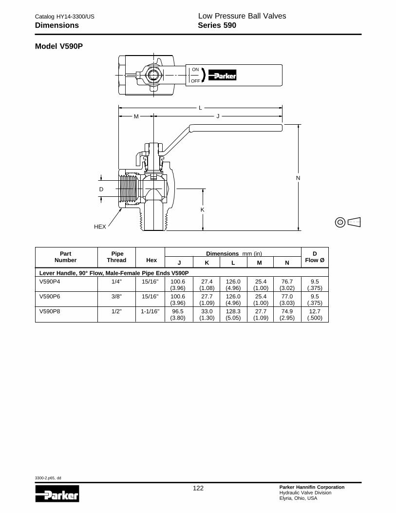
Catalog HY14-3300/US
3300-2.p65, dd
122 Parker Hannifin CorporationHydraulic Valve DivisionElyria, Ohio, USA
H
Low Pressure Ball ValvesSeries 590Dimensions
Part Pipe Dimensions mm (in) DNumber Thread Hex J K L M N Flow Ø
Lever Handle, 90° Flow, Male-Female Pipe Ends V590PV590P4 1/4" 15/16" 100.6 27.4 126.0 25.4 76.7 9.5
(3.96) (1.08) (4.96) (1.00) (3.02) (.375)
V590P6 3/8" 15/16" 100.6 27.7 126.0 25.4 77.0 9.5(3.96) (1.09) (4.96) (1.00) (3.03) (.375)
V590P8 1/2" 1-1/16" 96.5 33.0 128.3 27.7 74.9 12.7(3.80) (1.30) (5.05) (1.09) (2.95) (.500)
ON
OFF
LJM
N
D
K
HEX
Model V590P
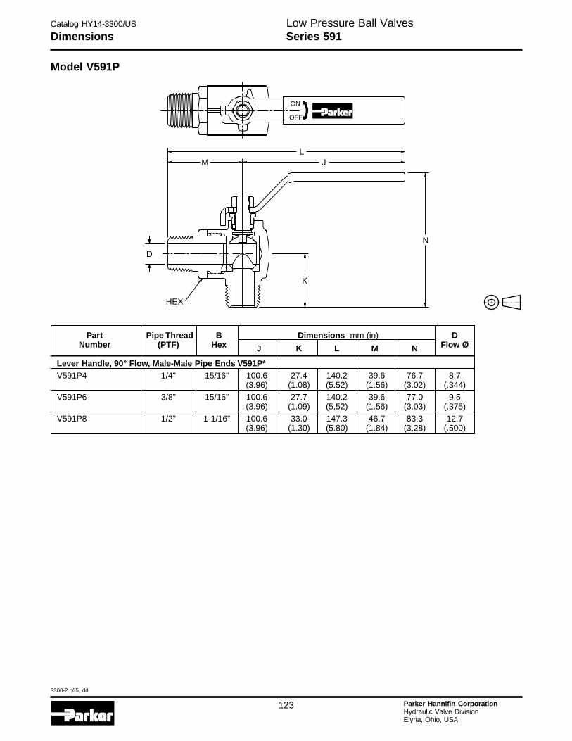
Catalog HY14-3300/US
3300-2.p65, dd
123 Parker Hannifin CorporationHydraulic Valve DivisionElyria, Ohio, USA
Low Pressure Ball ValvesDimensions Series 591
Part Pipe Thread B Dimensions mm (in) DNumber (PTF) Hex J K L M N Flow Ø
Lever Handle, 90° Flow, Male-Male Pipe Ends V591P*V591P4 1/4" 15/16" 100.6 27.4 140.2 39.6 76.7 8.7
(3.96) (1.08) (5.52) (1.56) (3.02) (.344)
V591P6 3/8" 15/16" 100.6 27.7 140.2 39.6 77.0 9.5(3.96) (1.09) (5.52) (1.56) (3.03) (.375)
V591P8 1/2" 1-1/16" 100.6 33.0 147.3 46.7 83.3 12.7(3.96) (1.30) (5.80) (1.84) (3.28) (.500)
HEX
D
K
N
M JL
ON
OFF
Model V591P
Catalog HY14-3300/US
3300-2.p65, dd
124 Parker Hannifin CorporationHydraulic Valve DivisionElyria, Ohio, USA
H
The items described in this document and other documents or descriptions provided by Parker Hannifin Corporation, its subsidiaries and its authorizeddistributors are hereby offered for sale at prices to be established by Parker Hannifin Corporation, its subsidiaries and its authorized distributors. Thisoffer and its acceptance by any customer ("Buyer") shall be governed by all of the following Terms and Conditions. Buyer’s order for any such items,when communicated to Parker Hannifin Corporation, its subsidiary or an authorized distributor ("Seller") verbally or in writing, shall constitute acceptanceof this offer.
paid by Buyer. Unless otherwise agreed, Seller shall have the right to alter,discard or otherwise dispose of any special tooling or other property in itssole discretion at any time.8. Buyer’s Property: Any designs, tools, patterns, materials, drawings,confidential information or equipment furnished by Buyer or any otheritems which become Buyer’s property, may be considered obsolete andmay be destroyed by Seller after two (2) consecutive years have elapsedwithout Buyer placing an order for the items which are manufactured usingsuch property, Seller shall not be responsible for any loss or damage tosuch property while it is in Seller’s possession or control.9. Taxes: Unless otherwise indicated on the face hereof, all prices andcharges are exclusive of excise, sales, use, property, occupational or liketaxes which may be imposed by any taxing authority upon the manufac-ture, sale or delivery of the items sold hereunder. If any such taxes mustbe paid by Seller or if Seller is liable for the collection of such tax, theamount thereof shall be in addition to the amounts for the items sold. Buyeragrees to pay all such taxes or to reimburse Seller therefore upon receiptof its invoice. If Buyer claims exemption from any sales, use or other taximposed by any taxing authority, Buyer shall save Seller harmless fromand against any such tax, together with any interest or penalties thereonwhich may be assessed if the items are held to be taxable.10. Indemnity For Infringement of Intellectual Property Rights: Sellershall have no liability for infringement of any patents, trademarks, copy-rights, trade dress, trade secrets or similar rights except as provided in thisPart 10. Seller will defend and indemnify Buyer against allegations ofinfringement of U.S. Patents, U.S. Trademarks, copyrights, trade dressand trade secrets (hereinafter ‘Intellectual Property Rights’). Seller willdefend at its expense and will pay the cost of any settlement or damagesawarded in an action brought against Buyer based on an allegation thatan item sold pursuant to this contract infringes the Intellectual PropertyRights of a third party. Seller’s obligation to defend and indemnify Buyeris contingent on Buyer notifying Seller within ten (10) days after Buyerbecomes aware of such allegations of infringement, and Seller having solecontrol over the defense of any allegations or actions including allnegotiations for settlement or compromise. If an item sold hereunder issubject to a claim that it infringes the Intellectual Property Rights of a thirdparty, Seller may, at its sole expense and option, procure for Buyer theright to continue using said item, replace or modify said item so as to makeit noninfringing, or offer to accept return of said item and return thepurchase price less a reasonable allowance for depreciation. Notwith-standing the foregoing, Seller shall have no liability for claims of infringe-ment based on information provided by Buyer, or directed to itemsdelivered hereunder for which the designs are specified in whole or partby Buyer, or infringements resulting from the modification, combination oruse in a system of any item sold hereunder. The foregoing provisions ofthis Part 10 shall constitute Seller’s sole and exclusive liability and Buyer’ssole and exclusive remedy for infringement of Intellectual Property Rights.If a claim is based on information provided by Buyer or if the design for anitem delivered hereunder is specified in whole or in part by Buyer, Buyershall defend and indemnify Seller for all costs, expenses or judgmentsresulting from any claim that such item infringes any patent, trademark,copyright, trade dress, trade secret or any similar right.11. Force Majeure: Seller does not assume the risk of and shall not beliable for delay or failure to perform any of Seller’s obligations by reasonof circumstances beyond the reasonable control of Seller (hereinafter‘Events of Force Majeure’). Events of Force Majeure shall include withoutlimitation, accidents, acts of God, strikes or labor disputes, acts, laws,rules or regulations of any government or government agency, fires,floods, delays or failures in delivery of carriers or suppliers, shortages ofmaterials and any other cause beyond Seller’s control.12. Entire Agreement/Governing Law: The terms and conditions setforth herein, together with any amendments, modifications and anydifferent terms or conditions expressly accepted by Seller in writing, shallconstitute the entire Agreement concerning the items sold, and there areno oral or other representations or agreements which pertain thereto. ThisAgreement shall be governed in all respects by the law of the State of Ohio.No actions arising out of the sale of the items sold hereunder or thisAgreement may be brought by either party more than two (2) years afterthe cause of action accrues.
9/91-P
1. Terms and Conditions of Sale: All descriptions, quotations, propos-als, offers, acknowledgments, acceptances and sales of Seller’s productsare subject to and shall be governed exclusively by the terms andconditions stated herein. Buyer’s acceptance of any offer to sell is limitedto these terms and conditions. Any terms or conditions in addition to, orinconsistent with those stated herein, proposed by Buyer in any accep-tance of an offer by Seller, are hereby objected to. No such additional,different or inconsistent terms and conditions shall become part of thecontract between Buyer and Seller unless expressly accepted in writingby Seller. Seller’s acceptance of any offer to purchase by Buyer isexpressly conditional upon Buyer’s assent to all the terms and conditionsstated herein, including any terms in addition to, or inconsistent with thosecontained in Buyer’s offer, Acceptance of Seller’s products shall in allevents constitute such assent.2. Payment: Payment shall be made by Buyer net 30 days from the dateof delivery of the items purchased hereunder. Amounts not timely paidshall bear interest at the maximum rate permitted by law for each monthor portion thereof that the Buyer is late in making payment. Any claims byBuyer for omissions or shortages in a shipment shall be waived unlessSeller receives notice thereof within 30 days after Buyer’s receipt of theshipment.3. Delivery: Unless otherwise provided on the face hereof, delivery shallbe made F.O.B. Seller’s plant. Regardless of the method of delivery,however, risk of loss shall pass to Buyer upon Seller’s delivery to a carrier.Any delivery dates shown are approximate only and Seller shall have noliability for any delays in delivery.4. Warranty: Seller warrants that the items sold hereunder shall be freefrom defects in material or workmanship for a period of 18 months fromdate of shipment from Parker Hannifin Corporation. THIS WARRANTYCOMPRISES THE SOLE AND ENTIRE WARRANTY PERTAINING TOITEMS PROVIDED HEREUNDER. SELLER MAKES NO OTHER WAR-RANTY, GUARANTEE, OR REPRESENTATION OF ANY KIND WHAT-SOEVER. ALL OTHER WARRANTIES, INCLUDING BUT NOT LIM-ITED TO, MERCHANTABILITY AND FITNESS FOR PURPOSE,WHETHER EXPRESS, IMPLIED, OR ARISING BY OPERATION OFLAW, TRADE USAGE, OR COURSE OF DEALING ARE HEREBYDISCLAIMED. NOTWITHSTANDING THE FOREGOING, THEREARE NO WARRANTIES WHATSOEVER ON ITEMS BUILT OR AC-QUIRED WHOLLY OR PARTIALLY, TO BUYER’S DESIGNS ORSPECIFICATIONS.5. Limitation Of Remedy: SELLER’S LIABILITY ARISING FROM ORIN ANY WAY CONNECTED WITH THE ITEMS SOLD OR THIS CON-TRACT SHALL BE LIMITED EXCLUSIVELY TO REPAIR OR RE-PLACEMENT OF THE ITEMS SOLD OR REFUND OF THE PURCHASEPRICE PAID BY BUYER, AT SELLER’S SOLE OPTION. IN NO EVENTSHALL SELLER BE LIABLE FOR ANY INCIDENTAL, CONSEQUEN-TIAL OR SPECIAL DAMAGES OF ANY KIND OR NATURE WHATSO-EVER, INCLUDING BUT NOT LIMITED TO LOST PROFITS ARISINGFROM OR IN ANY WAY CONNECTED WITH THIS AGREEMENT ORITEMS SOLD HEREUNDER, WHETHER ALLEGED TO ARISE FROMBREACH OF CONTRACT, EXPRESS OR IMPLIED WARRANTY, ORIN TORT, INCLUDING WITHOUT LIMITATION, NEGLIGENCE, FAIL-URE TO WARN OR STRICT LIABILITY.6. Changes, Reschedules and Cancellations: Buyer may request tomodify the designs or specifications for the items sold hereunder as wellas the quantities and delivery dates thereof, or may request to cancel allor part of this order, however, no such requested modification or cancel-lation shall become part of the contract between Buyer and Seller unlessaccepted by Seller in a written amendment to this Agreement. Accep-tance of any such requested modification or cancellation shall be atSeller’s discretion, and shall be upon such terms and conditions as Sellermay require.7. Special Tooling: A tooling charge may be imposed for any specialtooling, including without limitation, dies, fixtures, molds and patterns,acquired to manufacture items sold pursuant to this contract. Such specialtooling shall be and remain Seller’s property notwithstanding payment ofany charges by Buyer. In no event will Buyer acquire any interest inapparatus belonging to Seller which is utilized in the manufacture of theitems sold hereunder, even if such apparatus has been specially con-verted or adapted for such manufacture and notwithstanding any charges
Offer of Sale
Catalog HY14-3300/US
3300-2.p65, dd
122 Parker Hannifin CorporationHydraulic Valve DivisionElyria, Ohio, USA
H
Parker Hydraulics International Sales Offices
11/05
EuropeFranceParker Hannifin France SAS142, rue de la Foret74130 Contamine sur Arve, FranceTel: 33 450 25 80 25Fax: 33 450 03 67 37
Germany/SwitzerlandParker Hannifin GmbH & Co. KGPat-Parker-Platz 141564 Kaarst, GermanyTel: 49 (0) 2131 4016 0Fax: 49 (0) 2131 4016 9199
GreeceParker Hannifin CorporationAthens Representative Office197 Syngrou Av.171 21 Nea Smyrni, Athens, GreeceTel: 0030 210 933-6450Fax: 0030 210 933-6451
HungaryParker Hannifin CorporationHungarian Trade Representative OfficeH-1149 BudapestEgressy u. 100, HungaryTel: 36 12204155Fax: 36 14221525
IrelandParker Hannifin Ireland Ltd.Blackthorn Close,Stillorgan Industrial ParkBlackrock, Co Dublin, IrelandTel: 353 1 293 9999Fax 353 1 293 9900
ItalyParker Hannifin S.p.A.Via Privata Archimede 120094 Corsico (MI), ItalyTel: 39 02 451921Fax: 39 02 4479340
The NetherlandsParker Hannifin B.V.Edisonstraat 17575 AT Oldenzaal, The NetherlandsTel: 31 541 585000Fax: 31 541 585459
NorwayParker Hannifin A/SBerghaganPO Box 3008N-1402 Ski, NorwayTel: 47 64 911000Fax: 47 64 911090
PolandParker Hannifin Sp z.o.o.ul. Równolegla 8PL 02-435 Warsaw, PolandTel: 48 22 573 24 00Fax: 48 22 573 24 03
PortugalParker Hannifin Portugal, Lda.Travessa da Bataria 184 R/CDto./1 Esq.Leça da Palmeira-4450-625, PortugalTel: 351 22 9997360Fax: 351 22 9961527
Industrial SalesGreat Lakes Region3700 Embassy Parkway Suite 260Fairlawn, OH 44333 USATel: 330-670-2680Fax: 330-670-2681
Southern Region1225 Old Alpharetta Road Suite 290Alpharetta, GA 30005 USATel: 770-619-9767Fax: 770-619-9806
Chicago Region1163 E. Ogden AvenueSuite 705, #358Naperville, IL 60563 USATel: 630-964-0796Fax: 866-473-9274
Pacific Region8460 Kass DriveBuena Park, CA 90621Tel: 714-228-2510Fax: 714-228-2511
Eastern Region100 Corporate DriveLebanon, NJ 08833 USATel: 908-236-4121Fax: 908-236-4146
EuropeEurope Hydraulics GroupParker Hannifin CorporationParker House55 Maylands AvenueHemel Hempstead, HertsHP2 4SJ EnglandTel: 44 1442 458000Fax: 44 1442 458085
AustriaParker Hannifin GmbHBadener Strasse 12A-2700 Wiener Neustadt, AustriaTel: 43 2622 23501-0Fax: 43 2622 66212
BelgiumParker Hannifin SA NVParc Industriel Sud, Zone IIRue du Bosquet 23B-1400 Nivelles, BelgiumTel: 32 67 280900Fax: 32 67 280999
Czech RepublicParker Hannifin s.r.o.Parkerova 623250 67 Klecany, Czech RepublicTel: 420 284 083 111Fax: 420 284 083 112
DenmarkParker Hannifin Denmark A/SIndustriparken 372750 Ballerup, DenmarkTel: 45 43 56 04 00Fax: 45 43 73 31 07
FinlandParker Hannifin OyYlästöntie 16FIN-01510 Vantaa, FinlandTel: 358 9 476 731Fax: 358 9 4767 3200
North AmericaHydraulics Group Headquarters6035 Parkland BoulevardCleveland, OH 44124-4141 USATel: 216-896-3000Fax: 216-896-4031Motion & Control Sales Division651 Robbins Drive, PO Box 3500Troy, MI 48007-3500 USATel: 248-589-2400Fax: 248-577-4890Parker Hannifin CanadaMotion & Control Division – Milton160 Chisholm Drive MiltonOntario Canada L9T 3G9Tel: 905-693-3011Fax: 905-876-0788Motion & Control Division – Montreal2001 rue de l'aviationDorval, Quebec, H9P 2X6Tel: 514-684-3000Fax: 514-684-4191Motion & Control Division – Calgary3141B – 18th Street N.E.Calgary, Alberta T2E 7K8Tel: 403-291-9284Fax: 403-291-9285MexicoParker Hannifin de Mexico, S.A. C.VVia de Ferrocarril a Matamoros 730Apodaca, N.L. C.P. 66600, MexicoTel: 01-8181-566036 y 96
Parker Hannifin de MéxicoAv eje uno norte num 100Parque Industrial Toluca 2000Toluca, Mex C.P. 50100Tel: 52 722 2754200Fax: 52 722 2799308
Mobile SalesMobile Systems Division595 Schelter RoadSuite 100Lincolnshire, IL 60069 USATel: 847-821-1500Fax: 847-821-7600Pacific Region8460 Kass DriveBuena Park, CA 90621Tel: 714-228-2510Fax: 714-228-2511Great Plains Region931 Alice CourtSt. Charles, IL 60174 USATel: 630-377-0271Fax: 630-377-0271Midwest Region4494 32nd StreetGrinnell, IA 50112 USATel: 641-236-3694Fax: 641-236-8884Southern Region2300 Bush CircleCarrollton, TX 75007 USATel: 972-307-2949Fax: 972-307-9410Eastern Region100 Corporate DriveLebanon, NJ 08833 USATel: 610-330-0970Fax: 925-396-6481
(continued on next page)
Catalog HY14-3300/US
3300-2.p65, dd
123 Parker Hannifin CorporationHydraulic Valve DivisionElyria, Ohio, USA
Parker Hydraulics International Sales Offices
11/05
EuropeRomaniaHidro Consulting Impex SRLBucaresti Parker Representative OfficeBld. Ferdinand nr. 27 Sector 2RO-00001 Bucarest, RomaniaTel: 0040 21 252 1382Fax: 0040 21 252 3381
RussiaParker Hannifin LLCRossolimo st., 17, floor 4119021 Moscow, RussiaTel: 7 095 580 91 45Fax: 7 095 580 91 45
Parker Hannifin LLCBranch Office SakhalinZheleznodorozhnaya str., 174-A693008 Yuzhno-Sakhalinsk, RussiaTel: 7 4242 77 95 48Fax: 7 4242 77 27 42
SloveniaParker Hannifin CorporationVel. Bucna vas 7SI-8000 Novo Mesto, SloveniaTel: 386 7337 6650Fax: 386 7337 6651
SpainParker Hannifin España SAParque Industrial Las MonjasCalle Estaciones 828850 Torrejón de ArdozMadrid, SpainTel: 34 91 6757300Fax: 34 91 6757711
SwedenParker Hannifin ABFagerstagatan 51Box 8314SE-163 08 Spånga, SwedenTel: 46 (0)8 59 79 5000Fax: 46 (0)8 59 79 5110
TurkeyParker Hannifin CorporationMerter Is MerkeziGen. Ali Riza Gurcan Cad. No: 2 / 6734067 Merter, Istanbul, TurkeyTel: 90 212 482 91 06Fax: 90 212 482 91 10
UkraineParker Hannifin CorporationVul. Velyka Vasylkivska 9/2 Office 5901004 Kiev, UkraineTel: 380 44 494 2731Fax: 380 44 494 2730
United KingdomParker Hannifin plcTachbrook Park DriveTachbrook ParkWarwick, CV34 6TU, EnglandTel: 44 1926 317878Fax: 44 1926 317855
South AfricaParker Hannifin Africa Pty Ltd.Parker Place10 Berne Avenue AeroportP.O. Box 1153Kempton Park 1620,Republic of South AfricaTel: 27 11 9610700Fax: 27 11 3927213
Middle EastAzerbaijanParker Hannifin plcAzpar, Technical Representative140 Alovsat Guliyev St. Apt. 10370000 Baku, AzerbaijanTel: 994 12 498 3966Fax: 994 12 498 3966
KazakhstanParker HannifinGateway Ventures CA LTD,Representative7A Kabanbai Batira480100 Alamty, KazakhstanTel: 7 3272 505 800Fax: 7 3272 505 801
United Arab EmiratesParker Hannifin CorporationPO Box 46451Abu Dhabi, United Arab EmiratesTel: 971 2 6788587Fax: 971 2 6793812
Asia PacificAsia Pacific HeadquartersParker Hannifin Hong Kong Ltd.8/F, Kin Yip Plaza, 9 Cheung Yee StreetCheung Sha Wan, KowloonHong KongTel: 852 2428 8008Fax: 852 2480 4256
Australia HeadquartersParker Hannifin Pty Ltd.9 Carrington RoadCastle Hill, NSW 2154, AustraliaTel: 612 9634 7777Fax: 612 9842 5111
China HeadquartersParker Hannifin Fluid Power Systems& Components (Shanghai) Co., Ltd.280 Yunqiao Road,Jinqiao Export Processing ZoneShanghai 201206, ChinaTel: 86 21 5031 2525Fax: 86 21 5834 3714
Parker Hannifin Beijing OfficeSuite B9-11, 21/F, Hanwei PlazaNo. 7 Guanghua RoadChaoyang DistrictBeijing, 100004, ChinaTel: 86 10 6561 0520Fax: 86 10 6561 0526
IndiaParker Hannifin India Pvt Ltd.Plot No. EL-26, TTC Industrial AreaMahape, Navi Mumbai 400 709, IndiaTel: 0091 022 56137081/2/3/4Fax 0091 022 27686841, 27686618
Asia PacificJapanParker Hannifin Japan Ltd.4-2-1 Tsujido-Shinmachi,Fujisawa, Kanagawa, 251-0042, JapanTel: 81 466 35 3050Fax: 81 466 35 2019
Korea HeadquartersParker Hannifin Korea Ltd.Daehwa Venture Plaza, 6F169 Samsung-DongKangnam-ku, Seoul, 135-090, KoreaTel: 82 2 559 0400Fax: 82 2 556 8187
SingaporeParker Hannifin SingaporeNo. 11, Fourth Chin Bee RoadJurong Town, Singapore, 619702Tel: 65 6887 6300Fax: 65 6265 5125
TaiwanParker Hannifin Taiwan Co., Ltd.No. 40, Wuchiuan 3rd Rd.,Wuku Industrial ParkTaipei County, Taiwan 248, R.O.C.Tel: 886 2 2298 8987Fax: 886 2 2298 8982
ThailandParker Hannifin Thailand Co., Ltd.1023, 3rd floor, TPS buildingPattanakarn Road, SuanluangBangkok 10250, ThailandTel: 662 717 8140Fax: 662 717 8148
Latin AmericaPan American Division7400 NW 19th Street, Suite AMiami, FL 33126 USATel: 305-470-8800Fax: 305-470-8808ArgentinaParker Hannifin Argentina SAICStephenson 2711 esq. Costa Rica1667 TortuguitasBuenos Aires, ArgentinaTel: 54 3327 44 4129Fax: 54 3327 44 4199BrazilHydraulics DivisionParker Hannifin Ind. e Com. Ltda.Av. FredericoRitter, 1100Cachoeirinha RS, 94930-000 BrazilTel: 55 51 3470 9144Fax: 55 51 3470 3100ChileParker Hannifin Chile Ltd.a.Av. Americo Vespucio 2760-EConchali - Santiago, ChileTel: 56-2-623-1216Fax: 56-2-623-1421VenezuelaParker Hannifin de Venezuela, S.A.Av. Principal con calle MiraimaEdificio DrazaBoleita NorteCaracas, VenezuelaTel: 58 212 238 5422Fax: 58 212 239 2272
Parker’s CharterTo be a leading worldwide manufacturer of componentsand systems for the builders and users of durable goods.More specifically, we will design, market and manufac-ture products controlling motion, flow and pressure.We will achieve profitable growth through premiercustomer service.
Product InformationNorth American customers seeking product infor-mation, the location of a nearby distributor, or repairservices will receive prompt attention by calling theParker Product Information Center at our toll-freenumber: 1-800-C-PARKER (1-800-272-7537). In Europe,call 00800-C-PARKER-H (00800-2727-5374).
The Fluid ConnectorsGroup designs, manufacturesand markets rigid and flexibleconnectors, and associatedproducts used in pneumaticand fluid systems.
The Hydraulics Groupdesigns, produces and marketsa full spectrum of hydrauliccomponents and systems tobuilders and users of industrialand mobile machinery andequipment.
The Automation Groupis a leading supplier of pneu-matic and electromechanicalcomponents and systems toautomation customers world-wide.
The Seal Group designs,manufactures and distributesindustrial and commercialsealing devices and relatedproducts by providingsuperior quality and totalcustomer satisfaction.
The Filtration Groupdesigns, manufactures andmarkets quality filtration andclarification products, provid-ing customers with the bestvalue, quality, technical sup-port, and global availability.
The InstrumentationGroup is a global leader inthe design, manufacture anddistribution of high-qualitycritical flow components forworldwide process instrumen-tation, ultra-high-purity, medi-cal and analytical applications.
About Parker Hannifin CorporationParker Hannifin is a leading global motion-controlcompany dedicated to delivering premier customerservice. A Fortune 300 corporation listed on the NewYork Stock Exchange (PH), our components and sys-tems comprise over 1,400 product lines that controlmotion in some 1,000 industrial and aerospace mar-kets. Parker is the only manufacturer to offer itscustomers a choice of hydraulic, pneumatic, andelectromechanical motion-control solutions. Our Com-pany has the largest distribution network in its field,with over 7,500 distributors serving nearly400,000 customers worldwide.
Parker Hannifin Corporation6035 Parkland Blvd.Cleveland, Ohio 44124-4141Telephone: (216) 896-3000Fax: (216) 896-4000www.parker.com
Parker Hannifin Corporation
The Aerospace Group isa leader in the development,design, manufacture and ser-vicing of control systems andcomponents for aerospace andrelated high-technology mar-kets, while achieving growththrough premier customerservice.
The Climate & IndustrialControls Group designs,manufactures and markets sys-tem-control and fluid-handlingcomponents and systems torefrigeration, air-conditioningand industrial customersworldwide.
6/99
Catalog HY14-3300/US,5M, 5/06, PageLitho
Parker Hannifin CorporationHydraulic Valve Division520 Ternes AvenueElyria, Ohio, 44035 USATel: (440) 366-5200Fax: (440) 366-5253www.parker.com/hydraulicvalve
For the latest hydraulic valve informationwww.parker.com/hydraulicvalvewww.parker.com/hydraulicvalvewww.parker.com/hydraulicvalvewww.parker.com/hydraulicvalvewww.parker.com/hydraulicvalve
To locate your nearest hydraulic valve distributorwww.parker.com/hyd/distlocwww.parker.com/hyd/distlocwww.parker.com/hyd/distlocwww.parker.com/hyd/distlocwww.parker.com/hyd/distloc
For North America, Europe and the rest of the worldregional offices, see Parker Hydraulics InternationalSales Offices at the back of this catalog.
Bulletin HY14-2400/USCatalog CD HY14-2400/US (included inside brochure)
Bulletin HY14-2530/USCatalog CD HY14-2530/US (included inside brochure)
Parker Hydraulic Valve wants to keep you informed.Listed below are connection opportunities for youto resource additional information or speak directlywith the industry’s most knowledgeable hydraulicvalve professionals.
To order literature or locate a distributor by phone1-800-C-Parker1-800-C-Parker1-800-C-Parker1-800-C-Parker1-800-C-Parker