in-plane bandpass regulation check valve in heat …
TRANSCRIPT

IN-PLANE BANDPASS REGULATION CHECK VALVE IN HEAT-SHRINK PACKAGING FOR DRUG DELIVERY
R. Lo and E. Meng University of Southern California, Los Angeles, California, USA
ABSTRACT
The first check valve featuring dual regulation of in-plane flow and heat-shrink tubing packaging is presented. This modular design is optimized for integration into low-profile fluidic devices requiring flow control, such as drug delivery devices. Theoretical and finite-element-modeling (FEM) analyses were performed to guide valve design and these results were confirmed experimentally. The valve regulates flow between 150-900 mmHg (20-120 kPa) and withstands >500 mmHg (66.7 kPa) of reverse pressure. The heat-shrink packaging scheme does not require adhesives and is extremely robust (>2000 mmHg without leakage).
INTRODUCTION
The out-of-plane orientation of typical MEMS check valves can complicate the process of fluidic packaging. We previously presented an ocular drug delivery device with a simple check valve [1]. The device comprised a drug reservoir for storage of pharmaceutical solutions, a flexible cannula for directed delivery to diseased tissues, and a flow regulating check valve integrated at the tip of the cannula. This check valve prevented bodily fluids from backflowing into the drug reservoir but lacked over-pressure protection to prevent accidental dosing. Also, its out-of-plane orientation could result in contact with tissues limiting its practical in vivo implementation. Furthermore, the valve was integrated into a cannula having rectangular geometry which prevented tight seals with the tissue at the incision site after suturing.
Thus, we propose a new modular valve paradigm that incorporates both a pressure limiting safety feature and surgically-friendly medical grade heat-shrink tubing packaging scheme. The round heat-shrink tubing is also the durg delivery cannula (Figure :1). This valve paradigm is easily adapted for use in other microfluidic systems.
Figure :1 Surgical model of a MEMS ocular drug delivery device featuring a valve packaged in a biocompatible heat-shrink tube. The valve is comprised of four modular components (inset): valve seat, pressure responsive valve plate, a spacer, and pressure limiter. DESIGN
The modular valve consists of four stacked disks: valve seat, pressure responsive valve plate, spacer plate, and pressure limiter (Figure 2).
Figure 2: Photo of the valve components (valve seat, valve plate, spacer plate, and pressure limiter), heat–shrink tube, and fully assembled valve (ruler divisions = 1 mm)
The valve operates in a manner analogous to a bandpass filter and allows fluid flow when the forward pressure exceeds the valve cracking pressure; flow ceases when the closing pressure is reached. A SU-8 spacer plate defines the distance between the movable valve plate and pressure limiter plate and thus the operating pressure range (opening and closing pressures). Valve components are stacked together and packaged into a biocompatible 22G fluorinated ethylene propylene (FEP) heat-shrink tube (Figure 3). The circular tube facilitates incision/tube sealing with sutures. This packaging method is extremely robust and does not require any adhesives.
Figure 3: a) Side view and b) top view of the packaged valve in FEP heat-shrink tube. The valve was placed inside the tube utilizing a custom-made jig and then heated to 215 ºC at 1.5 ºC/min, and cooled at the same rate to room temperature.
The valve dimensions were selected to meet the
surgical requirements; a 1 mm incision is permitted to insert the cannula/valve. Therefore, a 900 μm diameter valve was chosen leaving 100 μm for the packaging. The thickness of the spacer and valve plates was determined by FEM analysis and using the relationship governing large-deflections in a flexible plate of uniform thickness (eq. 1,2). Maximum deflection (wmax) can be calculated from plate thickness (t), applied pressure (p), plate radius
978-1-4244-2978-3/09/$25.00 ©2009 IEEE 236

(a), and flexural rigidity (D). Flexural rigidity is a function of Young’s modulus (E), plate thickness (t), and Poisson’s ratio (υ) [2].
Dpa
tww
64)486.01(
4
2
max2
max =+ (1)
)1(12 2
3
υ−= EtD (2)
Three different valve plate designs (hole, straight
arm, and s-shape arm) were investigated (Figure 4). Each design yielded different deflection behaviors and thus differing bandpass flow regulating characteristics (e.g. opening and closing pressure and flow resistance). FEM estimations and theoretical analyses were used to assign valve geometries such that the operational pressure range would be limited at the lower bound by normal intraocular pressure (IOP), <35 mmHg (4.67kPa), and an upper bound of 1000 mmHg (133.3kPa) (Table 1).
Figure 4: Three different valve plate designs a) hole, b) straight arm, and c) s-shape arm. Table 1: Dimensions of valve components, including the three valve designs (hole, straight arm, s-shape arm). All components are 900 μm in diameter.
Valve Seat/
Pressure Limiter
Hole Valve Plate
Straight Arm
Valve Plate
S-Shape Arm
Valve Plate
Spacer Plate
Material SU-8 MDX4-4210
MDX4-4210
MDX4-4210 SU-8
Thickness [µm] 200 75 75 75 40
FABRICATION SU-8 Valve Seat and Pressure Limiter
The SU-8 valve seat and SU-8 pressure limiter were fabricated using a two-layer SU-8 process (Figure 5). First, a soda-lime wafer (Mark Optics, Santa Ana, CA) was pretreated with Omnicoat (MicroChem, Newton, MA), a SU-8 release layer. Three layers of Omnicoat were applied (3000 rpm, 30 sec) with a bake step (1 min at 200 ºC) performed after each coat (Figure 5a). Three coats facilitated component release from the substrate; these extra layers of Omnicoat resulted in a reduction in the time and temperature necessary to release the SU-8. A 160 μm layer of SU-8 2100 (MicroChem, Newton, MA) formed the base section (Figure 5b,c). A 40 μm layer was added to form the features in the valve seat and pressure limiter (Figure 5d-f). The wafer was immersed in Remover PG (MicroChem, Newton, MA) for 5 minutes to separate the SU-8 components from the wafer (Figure 5g). The components were rinsed (IPA and DI H2O) and then hardbaked at 215 ºC for 1 hour. This final step annealed
the SU-8 components to improve thermal resistance for the subsequent heat-shrink packaging process.
Figure 5: Fabrication process for the valve seat and pressure limiter plates. SU-8 Spacer The 40 μm thick spacer plate was also fabricated on an Omnicoat-coated soda lime wafer using SU-9 2050 (Figure 6a-d). Spacer plates were released from the substrate using Remover PG and rinsed using IPA and DI H2O (Figure 6e).
Figure 6: Fabrication process for the SU-8 spacer plate. Valve Plate The valve plate was fabricated by casting medical grade silicone (MDX4-4210, Dow Corning, Midland, MI) against a SU-8 master. The SU-8 master was created on a soda lime wafer using SU-8 2050. 4 μm of Parylene C (Specialty Coating Systems, Inc., Indianapolis, IN) was vapor deposited onto the wafer to prevent the SU-8 from delaminating from the wafer due to thermal mismatch with the substrate [3]. A 75 μm layer of SU-8 2050 defined the valve plate thickness (Figure 7a-c). MDX4-4210 (10:1 base to curing agent ratio), was poured onto the mold and degassed under vacuum. Excess silicone was removed with a metal squeegee (Figure 7d) [4]. The silicone was cured at room temperature for 48 hours to minimize shrinkage. Then valve plates where separated from the mold (Figure 7e).
Figure 7: Fabrication process for the valve plate using an SU-8 master mold. Valve Packaging in Heat-Shrink Tubing
The valve was packaged in the heat-shrink tubing using a custom-made Teflon jig with a stainless steel post (813 μm diameter). A 22G (inner diameter prior to shrinkage: 914.4 μm, maximum wall thickness: 254 μm) 1.3:1 shrink ratio FEP heat-shrink tube (Zeus Industrial Products Inc., Orangeburg, SC) was placed around the post followed by the four valve components (valve seat, valve plate, spacer plate, pressure limiter) (Figure 8a). A second Teflon block with a matching and adjustable stainless steel post was aligned and secured such that the two posts held the valve assembly in place while the FEP
237
tubing was slipped it (Figure 8b). The entire jig was placed in an oven and heated to 215 ºC at a rate of 1.5 ºC/min; baked for 30 minutes, and then cooled to room temperature at the same rate to limit the thermally induced stress on SU-8 (Figure 8c). The jig was disassembled and the packaged valve was removed from the posts (Figure 8d).
The final outer diameter of the valve and packaging was 1.23 ± 0.004 μm (n=7, mean ± SE); while the outer diameter of the tube surrounding the valve was 1.04 ± 0.006 μm (n=21, mean ± SE). The post size was chosen to provide the largest possible surface area on which to balance the valve, however the final dimension for the tube outer diameter was limited by the stainless steel post.
Figure 8: Process for packaging valve in heat-shrink tubing. EXPERIMENTS AND RESULTS Valve Plate Deflection and Stress Analysis
Valve plate deflection and stress distribution for various stages of valve operation were modeled using FEM analysis (Figure 9). These stages include the valve at rest, opening under application of forward pressure, and closure at higher forward pressures.
Figure 9: FEM images of valve plate deflection under a) negligible forward pressure, b) 100 mmHg, c) 500 mmHg, and d) 10000 mmHg (used to visually exaggerate the valve closing mechanism). Forces between the valve seat and plate were not modeled; therefore the valve opened for any non-zero applied forward pressure.
Under forward applied pressure (1000 mmHg, 133.3 kPa), the maximum stress on the valve plate (0.99 MPa) was concentrated at the outer edge of contact with the valve seat. The stress was <20% of MDX4-4210 tensile strength (5 MPa) and significantly less than the tensile strength of SU-8 (60 MPa). Reverse pressure (500 mmHg, 66.7 kPa) analysis verified the stress on the valve (0.46 MPa) was at least an order of magnitude less than the tensile stress of MDX4-4210 or SU-8 (Figure 10b). Additionally, the valve plate deflected <7 μm under reverse pressure, maintaining an effective seal between the valve plate and valve seat (Figure 10b). Normal IOP ranges are 5-35 mmHg (4.67 kPa), thus the valve can withstand reverse pressure conditions greater than 10 times the IOP without failing.
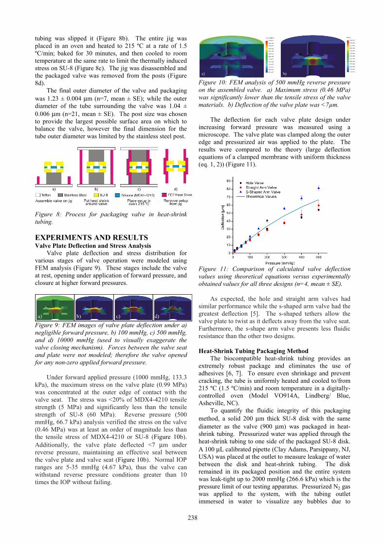
Figure 10: FEM analysis of 500 mmHg reverse pressure on the assembled valve. a) Maximum stress (0.46 MPa) was significantly lower than the tensile stress of the valve materials. b) Deflection of the valve plate was <7µm.
The deflection for each valve plate design under increasing forward pressure was measured using a microscope. The valve plate was clamped along the outer edge and pressurized air was applied to the plate. The results were compared to the theory (large deflection equations of a clamped membrane with uniform thickness (eq. 1, 2)) (Figure 11).
Figure 11: Comparison of calculated valve deflection values using theoretical equations versus experimentally obtained values for all three designs (n=4, mean ± SE).
As expected, the hole and straight arm valves had similar performance while the s-shaped arm valve had the greatest deflection [5]. The s-shaped tethers allow the valve plate to twist as it deflects away from the valve seat. Furthermore, the s-shape arm valve presents less fluidic resistance than the other two designs.
Heat-Shrink Tubing Packaging Method
The biocompatible heat-shrink tubing provides an extremely robust package and eliminates the use of adhesives [6, 7]. To ensure even shrinkage and prevent cracking, the tube is uniformly heated and cooled to/from 215 ºC (1.5 ºC/min) and room temperature in a digitally-controlled oven (Model VO914A, Lindberg/ Blue, Asheville, NC).
To quantify the fluidic integrity of this packaging method, a solid 200 μm thick SU-8 disk with the same diameter as the valve (900 μm) was packaged in heat-shrink tubing. Pressurized water was applied through the heat-shrink tubing to one side of the packaged SU-8 disk. A 100 μL calibrated pipette (Clay Adams, Parsippany, NJ, USA) was placed at the outlet to measure leakage of water between the disk and heat-shrink tubing. The disk remained in its packaged position and the entire system was leak-tight up to 2000 mmHg (266.6 kPa) which is the pressure limit of our testing apparatus. Pressurized N2 gas was applied to the system, with the tubing outlet immersed in water to visualize any bubbles due to
238

leakage. The packaged system was also able to withstand up to 2000 mmHg (266.6 kPa).
Valve Operation
The behavior of a packaged valve (hole valve plate) was determined using a custom-made jig and pressure system. Pressurized water (0-1000 mmHg, 0-133.3 kPa) was applied in incremental steps to the valve inlet. The flow rate from the packaged valve was measured using a 100 μL calibrated pipette placed at the valve outlet. The system was held at each test pressure set point for 5 minutes to allow the system to equilibrate.
The valve cracking pressure was 150 mmHg (20 kPa) and closed at a pressure of 900 mmHg (120 kPa) for the hole valve plate design (Figure 12). Minimal leakage, less than 18 times peak flow, was observed after valve closure. The valve was able to withstand reverse pressures in excess of 500 mmHg (66.7 kPa) without leaking. The valve operating range is much greater than normal and abnormal IOP values, preventing the valve from opening due to normal eye pressures or transient fluctuations (e.g. as a result of flying or sneezing).
Figure 12: Bandpass regulation of fluid flow was verified on a packaged valve (hole valve plate). Pressurized DI water was applied to the inlet of a package valve and flow rate was measured using a 100 µL calibrated pipette. CONCLUSION
A bandpass regulation, in-plane check valve packaged within biocompatible heat-shrink tubing without the use of adhesives is presented. The valve achieved bandpass regulation of pressurized water with a cracking pressure of 150 mmHg (20 kPa) and closing pressure of 900 mmHg (120 kPa). The valve was able to withstand a reverse pressure of 500 mmHg (66.7 kPa) without leaking. The package is very robust and can withstand water and N2 gas pressures in excess of 2000 mmHg (266.6 kPa). Packaged valves were incorporated into a surgical model of the drug delivery device (made of MDX4-4210 with a stainless steel ring and PEEK baseplate) that will be used for ex vivo and in vivo validation of valve operation (Figure 13).
Figure 13: The valve was incorporated into a surgical model containing a drug reservoir for in vivo testing (ruler divisions = 1 mm). The valve is modular and easily replaced with another valve. ACKNOWLEDGEMENTS
This work was funded by the NIH/NEI under award number R21EY018490. The authors would like to thank Dr. Donghai Zhu, Benjamin Lee, and the members of the USC Biomedical Microsystems Laboratory for their assistance with this project. REFERENCES [1] R. Lo, P. Y. Li, S. Saati, R. Agrawal, M. S.
Humayun, and E. Meng, "A refillable microfabricated drug delivery device for treatment of ocular diseases," Lab on a Chip, vol. 8, pp. 1027-1030. 2008.
[2] A. C. Ugural, Stresses in Plates and Shells, 2nd ed. New York: McGraw-Hill, 1999.
[3] R. Lo and E. Meng, "Integrated and reusable in-plane microfluidic interconnects," Sensors and Actuators B: Chemical, vol. 132, pp. 531-539. 2008.
[4] R. Kee Suk, W. Xuefeng, K. Shaikh, and L. Chang, "A method for precision patterning of silicone elastomer and its applications," Journal of Microelectromechanical Systems, vol. 13, pp. 568-575. 2004.
[5] X.-Q. Wang, Q. Lin, and Y.-C. Tai, "Parylene micro check valve," Proceedings of the IEEE Micro Electro Mechanical Systems (MEMS) Orlando, Jan. 17-21, 1999, pp. 177-182.
[6] T. Pan, A. Baldi, and B. Ziaie, "A reworkable adhesive-free interconnection technology for microfluidic systems," Journal of Microelectromechanical Systems, vol. 15, pp. 267-272. 2006.
[7] T. Pan, J. D. Brown, and B. Ziaie, "An Artificial Nano-Drainage Implant (ANDI) for Glaucoma Treatment," presented at the 28th Annual International Conference of the IEEE Engineering in Medicine and Biology Society, 2006. EMBS '06., New York, Aug. 30- Sept. 3, 2006, pp. 3174-3177.
239