in situ pavement moduli from dynaflect...
TRANSCRIPT

102
sponse: Cohesive Soils. Journal of the Soil Mechanics and Foundation Division, ASCE, Vol. 69, No. SMl, pp. 115-146.
14. R.L. Kondner. A Hyperbolic Stress-Strain Formulation for Sands. Proc., 2nd Pan-American Conference on Soil Mechanics and Foundation Engineering, Brazil, Vol. 1, 1963, pp. 269-324.
15. R.E. Smith, M.I. Darter, and S.T. Herrin. Highway Distress Identification Manual. Interim Report. FHWA, U.S. Department of Transportation, March 1979.
16. L. Raad and J. L. Figueroa. Load Response of Transportation Systems. Journal of the Transpur tatlon Engineering Division, ASCE, Vol. 106, No. TEl, 1960, pp. 111-126.
17. H.G. Larew and G.A. Leonards. A Strength Criterion for Repeated Loads. Proc., HRB, National Research Council, Washington, D.C., 1962, pp. 529-556.
Transportation Research Record 1043
16. M.R. Thompson and Q.L. Roi.Juell. Resilient Properties of Subgrade Soils. Transportation Engineering Journal, Jan. 1979, pp. 71-69.
19. J.P. Mahoney and R.L. Lytton. Measurements of Pavement Performance Using Statistical Sampling Techniques. Research Report 207-2. Texas Transportation Institute, Texas A&M University, College Station, March 1978.
20. C.M. Walton, C-P. Yu, P. Ng, and s. Tobias. An Assessment of Recent State Truck Size and Weight Studies. Research Report 241-4. Center for Transportation Research, University of Texas at Austin, July 1982, pp. 113-116.
Publication of this paper sponsored by Committee on Strength and Deformation Characteristics of Pavement Sections.
In Situ Pavement Moduli from Dynaflect Deflection
SHAKIR HUSAIN and K. P. GEORGE
ABSTRACT
A complete pavement evaluation entails not only a condition survey, including load testing, but also in situ material characterization. With the simplifying, but justifiable, assumption that pavement materials are elastic under muviny wheel loads, they are characterized by a modulus and Poisson's ratio. This study develops a methodology and computer program to determine the in situ elastic modulus for each layer in a multilayer flexible pavement. The surface deflection basin measured using the Dynaflect, or similar devices that employ five or more deflection sensors, would be the primary input data in the program. Points on a two-dimensional surface deflection basin are fitted to field data. Iteration is required to match the measured with the computed points by adjusting the assumed values for the layer moduli. The Chevron program is used to predict deflections. A computerized pattern search technique, the mainstay of the iteration, accomplishes the task of matching the deflections by minimizing the sum of squared errors. The usefulness of the method is illustrated by comparing the outputs of this program with those of the "standard" OAF program developed for FHWA. Results are presented to show that the present method gives far more reasonable results than does the OAF program. Suggestions for improving the solution procedure when dealing with erratic or inconsistent deflection readings, or both, are discussed. The feasibility of using deflection data of other devices, for example falling weight deflectometer, in the present method is illustrated by example problems.
A pavement undergoes deterioration with time and traffic; therefore, rehabilitation or even reconstruction is required to extend its useful life. In situ structural strength (i.e., rema1n1ng life of existing pavement), if properly evaluated and accounted for in the design procedure, aids in reducing rehabilitation construction expenses. A complete structural evaluation may determine the adequacy of the pavement and enables the engineer to predict its
future service life with respect to the traffic using it. When pavement is found to be inadequate, the evaluation forms the basis for designing the improvements needed to provide service for a selected design period.
It is both useful and relevant for an engineer to have knowledge of the inherent mechanical properties of a pavement structure in order to calculate various responses (stresses and strains) throughout the

Husain and George
structure and to make a rational evaluation of its bearing capacity and useful structural lifetime in terms of traffic loading. Pavement response may be analyzed by the finite element method <.!J, elastic layer analysis based on Burmister 's theory (_~), the viscoelastic layer analysis (~_) , or other methods. One major difficulty in response analysis of pavement structures lies in having to determine the structural properties, such as elastic moduli, of pavement materials.
There are two possible methods for determining the elastic moduli of pavement materials. The first method is to conduct laboratory testing on either laboratory-compacted specimens or undisturbed samples taken from the pavement. Nondestructive testing is the second method. For example, surface deflect ions or deflection basins under known loading conditions, or both, have been widely used. Surface deflection basins may be determined using a Benkelman beam, Dynaflect, Road Rater, or other device. Because of its relatively higher degree of mobility, the Dynaflect is increasingly preferred for routine evaluation of highway pavements.
The question of how to estimate the material parameters in situ from surface deflections now arises. This problem is complicated because the material parameters are stress dependent. That is, the parameters estimated should preferably correspond to the magnitudes of stress or strain, or both, encountered under the actual loading condition the pavement is subjected to under wheel loads.
Theoretical solutions for determining elastic moduli of multilayer systems have been found (!,~);
for purposes of discussion, these solution procedures are grouped as follows: those employing deflection data from Dynaflect or Road Rater (i-~) and those making use of such devices as a falling weight deflectometer (9,10). Because a large number of highway agencies-~ the United States rely on Dynaflect or Road Rater for pavement evaluation, a review of the various methods related to those two devices is presented.
Vaswani (11) proposed a structural design procedure based ~ Dynaflect maximum deflection (DMD). The method proposed by Jimenez (12) using Dynaflect deflections assumes that the elastic modulus of the asphalt concrete (AC) is known (if not, it is assumed). This requirement constitutes the major limitation of this approach. Majidzadeh et al. (13) reported a system (designated the Ohio moduli program) that employs various combinations of Dynaflect deflection data such as the first sensor deflection (w1) plus the second sensor deflection (w2), w1 plus spreadabili ty, and so on. He also presented a nomog raphic solution of in situ modulus calculations for two-layer flexible pavements. In the overlay design program called OAF, Maj idzadeh and Ilves (2) employed a deflection matching technique for determining the in situ layer stiffnesses. The in situ asphalt modulus is compensated for temperature; and the base, subbase, and subgrade moduli are corrected for stress effects when test loads differ from design loads. While using field data to substantiate the applicability of the procedure, they experienced difficulties and commented, "The computed asphalt layer stiffness shows a large variation, and in a few cases the asphalt is stiffer than steel; nevertheless the values are reasonable in a great majority of the cases. • • • "
DMD data in conjunction with a series of curves were used in an FHWA study (14) to evaluate the stress-dependent subgrade moduli. That the asphalt materials need to be characterized in the laboratory is a major drawback of this method. Irwin (_~) used multilayer elastic theor¥--the BISTRO computer program--in conjunction with Dynaflect deflection
103
data to estimate the moduli of pavement layers. Because of the trial-and-error approach adopted, the basic algorithm used is inefficient to say the least. Following Irwin's approach, Kilareski and Anani (~), employing the Road Rater deflection basin, proposed a deflection matching procedure that requires the use of the BISAR computer program in conjunction with a successive approximation procedure. Kilareski and Anani, however, realized that many combinations of the elastic moduli yield deflections that match the observed ones. To obtain unique results, they introduced an additional condition of E1/E2 = 0.7 (E1 and E2 are moduli of first and second layers, respectively). Unfortunately, this ratio cannot be established a priori. Also, because the Dynaflect first sensor does not measure the deflection beneath the load, this program cannot be used with the Dynaflect.
Lytton and his coworkers (15) have developed another method, based on elastic---iayer theory, of predicting the layer moduli. This method makes use of an explicit expr~ssion for deflection, originally proposed by Vlasov and Leont' iev (16). The deflection equation is inverted by a nonlinear pattern search technique to determine the values of the layer moduli that would best fit the observed surface deflections. No doubt, the computer program using this approach in conjunction with Dynaflect deflections is as efficient as the authors claim. However, before it can be applied to other pavement sections, the user must develop several constants, five in all, for which no method exists as yet. Therefore, the applicability of this method is also quite limited.
To estimate the pavement material moduli, researchers have developed computer programs. As Maj idzadeh et al. (1) concede, the OAF program incorporating the state of the art of deflection matching techniques has resulted in unsatisfactory modulus values, especially when the AC surfacing is underlaid by stiff cemented layers. The first objective of this study, therefore, is to develop a "general" procedure for estimating in situ pavement layer moduli. The procedure, as is customary, uses the deflection response of pavement as the primary input. The entire deflection basin, rather than deflections at discrete locations, is used, however. A second objective is to demonstrate, with illustrative examples, the versatility of the method compared with the OAF program developed for FHWA.
METHODOLOGY FOR DETERMINING IN SITU MODULI
No direct, analytical solution exists that can uniquely determine the elastic moduli for a multilayer system from surface deflection measurements alone. A reverse solution is thus necessitated wherein a set of initial modulus values is "guessed" and the pavement response (deflections) is calculated using these values in conjunction with the Chevron program. The solution procedure requires that the assumed moduli be adjusted so that the objective function, which is the sum of squared differences of measured and computed surface deflect ions, tends to be a minimum.
This is not exactly a simple process because a multilayer system has an infinity of elastic modulus combinations that can result in the same single surface deflection. As indicated by other researchers (11~1 14), the problem is further compounded because the moduli of asphalt concrete are temperature sensitive and those of granular and subgrade materials are stress dependent.
Details of the method developed in this paper are presented in the following paragraphs. The flowchart
104 Transportation Research Record 1043
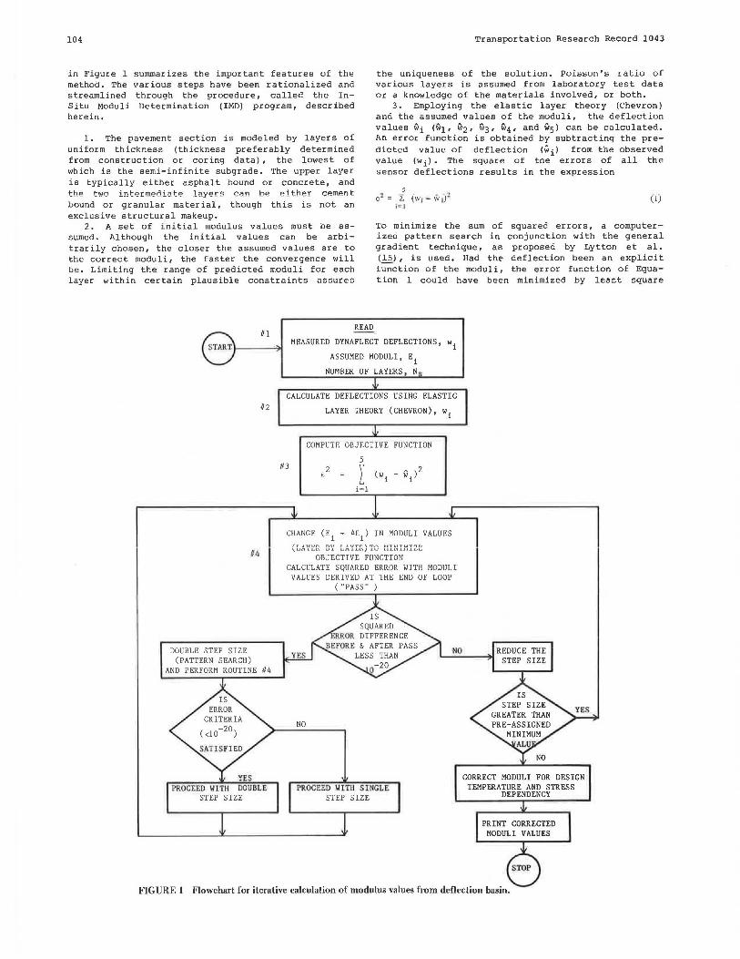
in Figure 1 summarizes the important features of the method. The various steps have been rationalized and streamlined through the procedure, called the InSitu Moduli Determination (IMD) program, described herein.
the uniqueness of the solution. Puhn;o11'o; ratio of various layers is assumed from laboratory test data or a knowledge of the materials involved, or both.
1. The pavement section is modeled by layers of uniform thickness (thickness preferably determined from construction or coring data) , the lowest of which is the semi-infinite subgrade. The upper layer is typically either asphalt bound or concrete, and the two intermediate layers ca.n be either cement bound or granular material, though this is not an exclusive structural makeup.
3. Employing the elastic layer theory (Chevron) and the assumed values of the moduli, the deflection values wi (w1, w2 1 w3, w4, and w5) can be calculated. An error function is obtained by subtracting the predicted value of deflection (wi) from the observed value (wi). The square of the errors of all the sensor deflections results in the expression
5
e~ = 2: (w1 - V.ir) ' 1 ~ 1
(1)
2. A set of initial modulus values must be assumed. Although the initial values can be arbitrarily chosen, the closer the assumed values are to the correct moduli, the faster the convergence will be. Limiting the range of predicted moduli for each layer within certain plausible constraints assures
To minimize the sum of squared errors, a computerized pattern search in conjunction with the general gradient technique, as proposed by Lytton et al. ( 15) , is used. Had the deflection been an explicit function of the moduli, the error function of Equation 1 could have been minimized by least square
DOUBLE STEP SIZE (PATTERN SEARCH)
111
112
AND PERFORM ROUTINE #4
PROCEED WITH DOUBLE STEP SIZE
READ
MEASURED DYNAFLECT DEFLECTIONS, w1 ASSUMED MODULI, Ei
NUMBER OF LAYERS, N
CALCULATE DEFLECTIONS USING ELASTIC
LAYER THEORY (CHEVRON), w1
113
COMPUTE OBJECTIVE FUNCTION
5 2
E \ ( A )2 l wi - wi
i=l
CHANGE (Ei + 6E1
) IN MODULI VALUES /TAUT.'n UV TAVt:'n\"T'A MT~TTMT'7T.' \UClJ.Lol\. .UJ. UC'l..LLIL\./ .LV 11.1.11.1.11.1.L..LI
OBJECTIVE FUNCTION CALCULATE SQUARED ERROR WITH MODULI
VALUES DERIVED AT THE END OF LOOP ("PASS" )
NO REDUCE THE L__:__:::. __ _,.. STEP SIZE
NO
PROCEED l,/lTll SINGLE STEP SIZE
CORRECT MODULI FOR DESIGN TEMPERATURE AND STRESS
DEPENDENCY
PRINT CORRECTED MODULI VALUES
FIGURE 1 Flowchart for iterative calculation of modulus values from deflection basin.

Husain and George
techniques. The pattern search, replacing the simple least square analysis, therefore, permits the use of more realistic nonlinear equations that relate the observed values of deflection to the independent variables, modulus values in this instance.
The program starts with the initial set of moduli and modifies these initial estimates by a preassigned value, designated as "step size," in subsequent iterations. Unlike other programs (8,10), the IMD program starts from the surface layer and proceeds to the subgrade; when through once, it is said to have completed a pass. For each modification of a given layer modulus, the square of error is calculated and compared with the error calculated in the preceding step; if it is smaller than the previous error, it replaces the earlier one and the corresponding change in the layer modulus is incorporated. On completing a pass, if the difference in squared error before and after the pass falls below a specified criterion (<lo-z• in the algorithm), the program resorts to a pattern search whereby the step size is doubled. Alternatively, a step size reduction is instituted should the criterion for squared error not be satisfied. Whether the doubled step size, according to the pattern search, is acceptable or not is governed by the squared error er i ter ion. Step size is decreased as the solution procedure advances, eventually terminating the program when the step size reaches a small preassigned value desired by the programmer. A relevant flow diagram and other details of this calculation routine can be found elsewhere (17). The set of values thus obtained is the "best" estimate of the in situ layer moduli for given loading and environmental conditions. To reduce them to the standard conditions, however, some corrections must be made.
Temperature Correction
The temperature of the pavement fluctuates wi th diurnal and seasonal temperature variations. It is known that the modulus of AC decreases (consequently the deflection increases) with increase in pavement temperature (18). For the modulus values calculated at various temperatures to be comparable, they should be adjusted to a standard temperature, usually designated as the design temperature, conveniently chosen at 60°F in this study.
Determination of the average temperature of the AC layer during field measurements is a prerequisite to making the corrections. Graphs (Figures 2a and 2b) developed by Southgate (19) are recommended for this purpose. Figure 2a shoulClbe used for AC layers thicker than 2 in. and Figure 2b for AC layers 2 in. or less thick.
The AC modulus at the test temperature is modified so that at the design temperature [60°F (15°C)], with the simplifying assumption, the deteriorated asphalt concrete exhibits a temperature dependency identical to that of the original AC mix. Typical moduli-temperature relationships of AC mixtures are shown in Figure 3. Making use of Figure 3, effective modulus at design - temperature can be obtained using the following equation:
E 1 = E 1 · EDES/EEXP (2)
where
EEXP
effective AC modulus at design temperature of 60°F (15°C), effective AC modulus at test temperature, modulus of original AC at design temperature, and modulus of original AC at test temperature.
1 60
.... £ 120 Q.
" c
... f ~ "' ;; ... E ~
80
40
0 0
(a)
40 80
Depth in Pavement, Inches
120
105
160 200 240
Pavement Temperature+ 5 Day Mean Air Temperature
160
(b) .... Depth In 0
1 z: 12 0 Pavement, 2 Q. Inches
" c
... 80
~ ~ :! " ... 40
E "
in Pavement, inches I-
0 0 40 80 120 160 200 240
Pavement Suri ace Temperature, °F
FIG R E 2 Tem1>erature prediction graphs: (a) pavements mor than 2 in . thick; (b) pavement.ls quul to or less than 2 _in. thick (1 9).
Correction for Stress Dependency
Because the moduli of s ubgrade materials and granular bases are stress dependent, the modulus computed with Dynaflect deflection basin tends to be larger than that under a 9-kip (40-kN) wheel load. To overcome this apparent limitation of the Dynaflect, the calculated subgrade modulus is corrected for stress dependency. The relationships generally applicable for granular base (subbase) and s ubgrade material s are, respectively,
-B Es = A,od 3
where
(3)
(4)
Es,Ess,Es moduli of base, subbase, and subgrade; A1 ,B1 = material constants for granular base; A2 ,B2 material constants for granular sub
base; material constants for the subgrade ; (cr1 + cr 2 + cr 3)/3 in situ bulk stress;
and cr 1 - (o2 + o3)/2 in situ deviatoric stress, in which 01, cr 2, and o3 are in situ principal stresses.
The weight of ove rlaying layers and the static load of the deflection measuring device constitute the i n s itu s tress at a point.
After the layer moduli have been determined, the Chevron program is used to compute the stress cr d and

106 Transportation Research Record 1043
4.0
2.0
curve• ,.,. 1.0 Vl•coaltr,
70°F )
Viacoel ly
.5 AC Gr1de n (106 70"F) ,.... .. AC· 4o 10 . Q. Ac-20 3. 2
'°o AC· 10 1 , 3 .. AC· 5 · 40 .. AC .2 .5 • 14
.; :I
:I ,, 0
:E Ml•tur" and TUI lnlorm"lon
u .1 Alphall Pl = - 1.o
·e Loading Frequency = 10 HZ.
I'll A1phal1 conl•nl =: 5.o o/o c Air Vold a = 5.o% >o
0 Percent Passing NO. 200~5.03
·04
0 20 40 60 80 100 120
Mean Pavement Temperature, ( "F )
FIGURE 3 Estimation of the asphalt concrete dynamic modulus as a function of mean pavement temperature.
e for the Dynaflect loading so that the constants Alr A2, and A3 can be determined. Note that the constants Bl, B2, and B3 should be known and are, therefore, a known input to the program.
The layer theory occasionally predicts tensile bulk stresses; in that event Equation 3 is not defined; consequently, A1 and A2 cannot be determined. (Note that compressive stresses are assumed to be positive.) The base and the subbase moduli may then be corrected using the following empirical relationship <.:?.>:
(5)
Input Data for IMO Program
Data, primarily material properties and response deflections, constitute the input for the IMO program. Pavement layer thickness and material character istics that include the "guessed" modulus values, Poisson's ratio, and the unit weights of each layer are the required material properties. Representative sensor deflections (five in all) comprise the remaining input data. A step-by-step procedure to prepare the input data and a sample input-output of an example problem can be found elsewhere (!1.l •
In summary, the IMO program uses a deflection matching technique to derive the in situ moduli of pavement layers. The computed AC modulus is subsequently corrected for temperature, and the base,
subbase, and subgcade moduli, as corrected for stress dependency.
COMPARATIVE STUDY OF IMO PROGRAM
___ ,.:, __ ._,_ c1J:JJ:J..L.L\.,:QLJ.L.t:1 are
The IMO program, as envisioned in this paper, enables the engineer to estimate the mechanistic properties of a pavement system employing pavement deflection data. This section is intended to provide at least partial verification of the program. Also illustrated are the application of the program and its use in evaluating pavement layer moduli employing input data from devices such as the Dynaflect or the falling weight deflectometer (FWD). Several IMD solutions are obtained from Dynaflect data ascertained from various sources. The following comparisons and evaluations establish the applicability of the program:
1. Comparing the IMO solution with the "standard" OAF program output;
2. Adjusting field deflection data to improve the solution procedure; and
3. Adapting the IMO program to other deflection data, for instance those from the FWD.
Comparison of IMO and OAF Solutions
Five sets of Dynaflect data (1.), given in Table 1, are analyzed for layer moduli using the IMO as well

Husain and George 107
TABLE 1 Measured Dynaflect Deflection Data (7)
Layer Thickness (in.) Deflection (mils) for Radial Distance of Section No. Location Surface Base Type of Data 10.00 in. 15.62 in. 26.00 in. 37.36 in. 49.03 in.
Abondale, Arizona Before overlay 4.0 8,0 Measured I .458 0.990 0.690 0.456 0.334
(gravel) Adjusted 1.450 1.100 0.690 0.456 0.310 After overlay 4.0 + 2.0-in. 8.0 Measured 0.926 0.748 0.576 0.354 0.252
overlay (gravel) Adjusted 0.926 0.800 0.550 0.380 0.260 2 Benson, Arizona
Before overlay 7.75 4,0 Measured I. I 80 0.668 0.430 0.249 0.140 (gravei) Adjusted 0.950 0.668 0.430 0.250 0.160
After overlay 7.75 + 1.75- 4.0 Measured 0.742 0.562 0.314 0.198 0.131 in. overlay (grnvel) Adjusted
3 Dead River, Arizona Before overlay 7.25 6.0 Measured 1.458 1.206 0.876 0.692 0.524
(cement Adjusted 1.520 1.206 0.910 0.660 0.524 treated)
After overlay 7.25 + 3.25- 6.0 Measured 0.750 0.712 0.600 0.508 0.356 in. overlay (cement Adjusted 0.820 0.750 0.620 0.480 0.356
treated) 4 Lupton, Arizona
Before overlay 4.0 6.0 Measured 1.152 0.912 0.664 0.524 0.358 (cement Adjusted 1.142 0.960 0.730 0.524 0.358
treated) After overlay 4.0 + 3.5-in. 6.0 Measured 0.642 0.534 0.456 0.372 0.302
overlay (cement Adjusted 0.622 0.564 0.456 0.362 0.302 treated)
5 Crazy Creek, Arizona Before overlay 4,0 6.0 Measured 1.597 1.300 0.890 0.580 0.426
(cement treated)
After overlay 4.0 + 2. 5-in. 6.0 Measured 0.860 0.718 0.598 0.470 0.333 overlay (cement
treated)
Note: I in.= 25.4 mm; I mil= 0.0254 mm.
as the OAF solutions, and the results are given in Table 2. Moduli before and after over lay also are compared in the table. Columns 6 and 10 list the effective thicknesses (heff) calculated in accordance with the following equation, which was originally proposed by Odemark (~:
also, the IMO program predicted moduli far better than those predicted by the OAF program. For example, the OAF program predicted moduli of 5,779,000 psi (39 846 MN/m') and 4,200 psi (29 MN/m 2 ), respectively, for AC surface and gravel base compared with IMO-estimated values of 70,000 psi (483 MN/m 2 ) and 91,400 psi (630 MN/m 2
). The reasonableness of the solutions is further assessed by comparing the effective thickness of a given pavement before and after overlay. It is gratifying to note that the difference between before and after effective thicknesses is approximately equivalent to the overlay thickness as listed in column 2 of Table 1. Effective thicknesses calculated in accordance with the OAF program do not meet this requirement, however. The foregoing results suggest that the !MD program can provide reasonable engineering solutions for flexible pavement systems of all types: full depth, gravel base, or cemented base.
k-1
herf = :E h; (E;/10,000) 1 13
i=I
where k is the number of layers and Ei is the modulus of the i th layer. For comparison purposes a 10 ,000-psi (69-MN/m') (21) subgrade is adopted in calculating the effective-thickness.
The OAF program consistently failed to predict the moduli of the cement-treated base (CTB) layer of a stabilized pavement. Without exception, the IMD program did predict reasonably accurate modulus values for the CTB layer. For gravel base pavements,
TABLE 2 Comparison of IMD and OAF Solutions
!MD Solution
Surface Base Section Modulus Modulus No. Location Overlay (psi) (psi)
Abondale, Before 70,000 91,400 Arizona After 250,000 45,100
2 Benson, Before 70,000 12,700 Arizona After 83,800 42,700
3 Dead River, Before 462,800 102,200 Arizona After 162,000 499,900
4 Lupton, Before 500,000 264,000 Arizona After 271,900 500,000
5 Crazy Creek, Before 174,900 89,900 Arizona After 500,000 292,900
Note: 1 psi= 6.89 kPa and 1 in. = 25.4 mm.
OAF Solution
Subgrade Surface Base Sub grade Modulus he ff Modulus Modulus Modulus he ff (psi) (in.) (psi) (psi) (psi) (in.)
6,300 24 5,779,000 4,200 11,700 39 6,800 31 239,000 77,900 7,600 33 7,800 19 100,000 15,700 8,500 21
10,300 26 443,000 5,100 16,100 37 5,100 39 117,000 5,100 7,300 49 412,000 7,400 6,900 33 241,000 7,100 9,400 45 458,000 10,400 4,900 23 109,000 5,400 8,800 45 350,000 8,200

108
Adjusting Field Deflection to Tmprove Rol11tion
Although the IMO program is a valuable tool for assessing pavement condition, in the event that inconsistent data (deflection readings describing the deflection basin) are input to the program, it can produce completely misleading results that could lead to erroneous conclusions. In the case of pavements, the deflection data are often subject to fairly wide ranges of interpretation simply because the engineer is working with materials that have been altered in varying degrees by the forces of nature. Therefore, it should be emphasized, as with most other types of numerical analysis, that the final results are as valid as the data used as input to the computations.
To even out systematic measurement errors, it is advised that several (no fewer than 10) sets of deflection readings be ascertained from the field with the mean values serving as input data for the IMD program. Nonetheless, the engineer should attempt a quick check of the reasonableness of the sensor deflections. The sensor readings defining a deflection basin might be satisfactory provided that (a) the deflection basin conforms to a concave (upward) surface in a log-log plot and (b) the rim of the basin (defined by sensor deflections w5 and w4 with or without w3) approaches a straight line in the same plot.
To illustrate the correction procedure, reference is made to Table 1, in which the raw deflection
0.30
0.40
0.60
.5 1.00 .. ·~ " c .5!
1.50
u .! i
2.0 0
Q
u .! ii 0.30 c >o Q
0.4 0
0.60
1.00
1.50 6 10 20
Transportation Research Record 1043
data, as well a5 the siame data after adju5tment in accordance with the foregoing discussion, are given. How the raw data of sections 3 and 4 are adjusted is graphically shown in Figure 4. The modulus values computed using the IMD program, with the raw and adjusted deflection basin, are given in Table 3. It is encouraging to note that slight adjustments in the deflection bowl have improved the predicted modulus values of AC surface and gravel or the cementtreated layer of pavements, 1 (B), 2 (B) , 2 (A) , and 3 (B). Several other results derived from deflection data (l), though not reported here in the interest of brevity, suggest that smoothing of the deflection bowl causes a decrease in the AC modulus with a corresponding increase in the modulus of the cementtreated layer; the effective thickness remains nearly the same.
As revealed by the results in Table 3, the modulus value of cement-treated base layer is increased after overlaying. This increase may be attributed to the enhancement of structural integrity of the pavement.
Layer Moduli Using IMD Program with FWD Data
Whether deflection data, other than generated data, can be input in the IMD examined in this section. Due in part to tility, the falling weight deflectometer for comparison. Recent investigations
00 Observed Deflections
Ajusted Deflection Basin
40 70 100
Dynaflectprogr am is its versa-is chosen (!Q) have
Geophone Location• (In.)
FIGURE 4 Comparison of Dynaflect deflection readings with the adjwted deflection basin.

Husain and George 109
TABLE 3 Improving In Situ Moduli by Modifying Deflection Basin
!MD Solution for Measured Deflection Data
!MD Solution for Adjusted Deflection Data
Surface Base Section Modulus Modulus No. Location Overlay (psi) (psi)
Benson, Before 70,000 12,700 Arizona After 83,800 42,700
2 Dead River, Before 463,000 102,000 Arizona After 162,000 500,000
3 Lupton, Before 500,000 264,000 Arizona After 272,000 500,000
Note: I psi= 6.89 kPa and I in. = 25.4 mm.
shown that the FWD loading system simulates the effect of a moving 9-kip (40-kN) wheel load and does so in terms of load intensity and, to a lesser extent, duration or time of loading (for a specific point on the pavement). To use the FWD deflection data in the IMO program, however, one modification must be made; that is, substitute the appropriate FWD load for the Dynaflect load.
The FWD data, as given in Table 4 (10), are input in the IMO program and in situ moduli are calculated and are given in Table 5. Tabulated for comparison purposes are the moduli calculated using the in situ stress-dependent elastic moduli, four-layer (ISSEM 4) program of Dynatest (10). The AC modulus of 875,900 psi (6038 MN/m 2 ) ~ 64.4°F (18°C) better corroborates the results reported elsewhere (13), including those of the authors of the ISSEM 4 program (10). Only AC modulus is temperature dependent, as indicated by the data in Table 5. The moduli of the layers, which include the base, subbase, and subgrade, however, are poorly predicted by the IMO program. See the first column of Table 4 for each temperature. As has been discussed in the previous section, the deflection basin is smoothed by slightly correcting the last sensor deflection (Table 4) with substantial improvement in the entire output (Table 5). Further improvement is sought by treating the pavement as a three-layer problem. It
Subgrade Surface Base Sub grade Modulus he ff Modulus Modulus Modulus he ff (psi) (in.) (psi) (psi) (psi) (in.)
7,800 19 70,000 57,900 8,800 22 10,300 26
5,100 39 208,800 90,000 4,800 32 7,300 49 332,000 90,000 7,100 46 6,900 33 330,600 499,500 6,800 35 9,400 45 300,000 500,000 9,400 45
is encouraging to note that all of the IMO-predicted moduli, with the AC modulus approaching the published values (13), show good agreement with those of the ISSEM 4 solution. The near equality of the effective thicknesses estimated with the two sets of modulus values (compare columns 6 and 11 of Table 5) may be offered as further proof of the overall agreement between the two solution procedures.
CONCLUDING REMARKS
A methodology and algorithm (the IMO program) for the evaluation of in situ moduli of individual pavement layers on the basis of measured Dynaflect deflections were presented. The algorithm is based on a deflection matching technique in conjunction with a multilayer elastic analysis such as Chevron. The deflection equation is inverted by a nonlinear pattern search technique to determine the values of the layer moduli that would best fit the observed surface deflections.
The applicability of the program is illustrated by comparing solutions with those of the standard OAF program <ll· Several comparisons, of which only a few are reported here, suggest that the IMO program predicts more realistic modulus values than does the OAF program. In addition, the IMO program
TABLE 4 Falling Weight Deflectometer Data for AC Surface= 7.0 in., Lime Rock Base= 10.43 in., and Suhhase = 12.20 in. (10)
Falling Weight Radial Distance (in.) Temperature Deflectometer (°F) Data 0.00 12.00 17.72 29.50 47.24
64.4 Deflection (mils) 8.070 5.905 4.645 3.031 1.614 8.070' 5 .905' 4.645' 3.031 a 2.000'
80.6 Deflection (mils) 7.047 4.173 3.149 2.027 1.181
8Adjusted deflections.
TABLE 5 Layer Moduli Using IMD Program with Falling Weight Deflectometer Data Listed in Table 4
Layer Mo du Ii (!MD Solution) Layer Moduli (ISSEM 4 Solution)
Surface Base Sub base Subgrade Surface • Base Sub base Subgrade Tempera- Modulus Modulus Modulus Modulus he ff Modulus Modulus Modulus Modulus he ff ture (°F) (psi) (psi) (psi) (psi) (in.) (psi) (psi) (psi) (psi) (in.)
64.4 875,000 89,100 9,200 63,000 65 1,027,000 68,000 29,000 29,000 70 757,400 87 ,500 20,000 39,300 67' 753,000 70,000 33,200 68b
80.6 566,000 67,100 59,600 66,300 69 586,400 91,000 49,000 45 ,000 69 544,400 79,600 52,400 69
Note: 1 in.= 25.4 mm, l psi= 6,89 kPa, and °C = (F - 32) (5/9). 8 Four-Jayer solution with adjusted deflections. bThree-layer solution,

110
is amenable to solution by deflection data from the falling weight de'flectometer.
A few poinlers may help Lo improve Lhe solulion procedure. First, the deflection data, if erroneous, should be corrected; and second, special attention should be paid to modeling the pavement. A set of consistent sensor readings would have the deflection basin conform to a concave (upward) surface in a log-log plot, and the rim of the basin approaches a straight line in the same plot. Experience also indicates that problems arise when the first and second sensor deflections are nearly equal, perhaps because of erroneous field data. Thin wearing surfaces do not contribute substantially to the strength of the pavement structure. For this reason, a wide range of modulus values may fit to satisfy deflection; therefore, this layer may be combined with an adjacent layer of similar characteristics. Finally, many pavement systems of more than three layers may well be solved using a three-layer model. For pavements of four or more layers the authors suggest reducing the system initially to a three-layer model; if it does not lend itself to solution, a four-layer model may be tried.
ACKNOWLEDGMENT
This paper is a part of a research study entitled "Overlay Design and Reflection Cracking Analysis for Pavements" sponsored by the Mississippi State Highway Department and the Federal Highway Administration, U.S. Department of Transportation. The authors acknowledge the suggestions and continued support offered by J.P. Sheffield and A.B. Crawley of the Highway Department.
REFERENCES
1. J.M. Duncan, c.L. Monismith, and E.L. Wilson. Finite Element Analysis of Pavements. In Highway Research Record 228, HRB, National Research Council, Washington, D.C., 1968, pp. 18-34.
2. D.M. Burmister. The General Theory of Stresses and Displacements in Layered Soil Systems I. Journal of Applied Physics, Vol. 16, 1945.
3. F. Moavenzadeh and J.E. Ashton. Analysis of Stresses and Displacements in a Three-Layer Viscoelastic System. Research Report 67-31. Department of Civil Engineering, Materials Research Laboratory, Ohio State University, Columbus, 1967.
4. F.H. Scrivner, C.H. Michilak, and w.M. Moore. calculation of the Elastic Moduli of a TwoLayer Pavement System for Measured Surface Deflections. In Highway Research Record 431, HRB, National Research Council, Washington, D.C., 1973, pp. 12-25.
5. w.H. Cogill. The Utilization of the Results of the Measurements of Surface Deflection Profiles as a Means of Estimating the Stiffness of Pavement Materials. Proc., Australian Road Research Record, Vol. 6, Part 4, 1972, pp. 142-149.
6. L.H. Irwin. Determination of Pavement Layer Moduli from Surface Deflection Data for Pavement Performance Evaluation. Proc., Fourth International Conference on Structural Design of Asphalt Pavements, University of Michigan, Ann Arbor, 1977, pp. 831-840.
7. K. Majidzadeh and G.J. Ilves. Flexible Pavement Overlay Design Procedures. Report FHWA/RD-81/032. FHWA, u.s. Department of Transportation, Vol. 1, 1981.
8. W.P. Kilareski and B.A. Anani. Evaluation of In-Si tu Moduli and Pavement Life from Deflection Basins. Proc., Fifth International Conference on Structural Design of Asphalt Pavements, Delft, The Netherlands, 1982, pp. 349-365.
Transportation Research Record 1043
9. P. Ullidtz. Overlay and Stage by Stage Design. Proc., Fourth International Conference on Structural Design of Asphalt Pavements, University of Michigan, Ann Arbor, 1977, pp. 722-735.
10. R.N. Stubstad and J. Sharma. Deriving Mechanistic Properties of Pavement Layers from Surface Deflections. International Conference on Computer Applications in Civil Engineering, Roorkee, India, 1979.
11. N.K. vaswani. Design of Flexible Pavements in Virginia Using AASHO Road Test Results. In Highway Research Record 291, HRB, National Research Council, Washington, D.C., 1969, pp. 89-103.
12. R.A. Jimenez. Pavement-Layer Modular Ratios from Dynaflect Deflections. In Transportation Research Record 671, TRB, National Research Council, Washington, D.c., 1978, pp. 23-28.
13. K. Majidzadeh. Dynamic Deflection Study for Pavement Condition Investigation. Ohio Department of Transportation, Columbus, 1974.
14. H.J. Treybig. Mechanistic Method of Pavement Overlay Design. In Transportation Research Record 700, TRB, National Research Council, Washington, D.C., 1979, pp. 72-77.
15. R.L. Lytton, C.H. Michalak, and T. Scullion. The Texas Flexible Pavement Design System. Proc., International Conference on Structural Design of Asphalt Pavements, Delft, The Netherlands, 1982.
16. v.z. Vlasov and N.N. Leont'iev. Beams, Plates, and Shells on Elastic Foundation (translated from Russian). Israel Program for Scientific Translations, Jerusalem, 1966.
17. s. Husain. In-Situ Pavement Moduli Using Dynaflect Deflection. M.S. thesis. University of Mississippi, University, 1984.
18. M.W. Witczak. Development of Regression Models for Asphalt Concrete Modulus for Use in MS-1 Study. The Asphalt Institute, College Park, Md., 1978.
19. H.F. Southgate. An Evaluation of Temperature Distribution Within Asphalt Pavements and Its Relationship to Pavement Deflection. Department o f 'f•ransport:at:ion of Kent:ucky, Frank f ort:, l~ G 8.
20. N. Odemark. Investigations as to the Elastic Properties of Soils and Design of Pavements According to the Theory of Elasticity. Staten Vaeginstitut, Stockholm, Sweden, 1949.
21. A.A.A. Molenaar and Ch.A.P.M. VanGurp. A Pavement Management System for Provincial Roads in The Netherlands. Proc., International Conference on Structural Design of Asphalt Pavements, Delft, The Netherlands, 1982.
The op1n1ons, findings, and conclusions expressed in this paper are those of the authors and not necessarily those of the Mississippi State Highway Department or the Federal Highway Administration. This paper does not constitute a standard, specification, or regulation.
Discussion Waheed Uddin*
Determination of in situ Young's moduli of pavement layers based on dynamic deflection basins is an area of growing interest for researchers involved in non-
*7201 Hart Lane, Apt. 2085, Austin, Tex. 78731

Husain and George
destructive testing of pavements. At the TRB 64th Annual Meeting, two other papers (.!_,ll were presented that were also based on the inverse application of layered linear elastic theor y to match measured deflection basins. A summary of different self-iterative computer programs is presented by Uddin et al. (1) .
As pointed -out by Uddin et al. (.!_), nearly all procedures require "guess" moduli in input data. The IMD program described by the authors is no exception and will produce user-dependent results. The moduli determined by the authors are apparently reasonable compared with OAF solutions but are not necessarily unique. The criterion selected by the authors for assuring uniqueness is "to limit the range of predicted moduli for each layer within certain plausible constraints." In other words, the proposed criterion for uniqueness is itself use r dependent. It is interesting to examine the range of moduli selected by the authors for their example problems of Tables 2, 4, and 5.
Some other aspects that would be of interest in this self-iterative procedure are reproducibility of results if the limits of modulus ranges are changed, an example of the validity of the procedure for a pavement of known material properties, and an example for applicability to rigid pavements. A discussion of these points by the authors is warranted. In the !MD program, temperature correction for the AC layer is applied before stress sensitivity is taken into account. In the writer's opinion, it is not appropriate to call the final moduli in situ moduli if the test temperature is different from the design temperature. A logical approach is to determine in situ moduli at test temperature before correcting AC modulus to the standard temperature (1).
The authors apparently believe the misconception that a Dynaflect basin will result in higher moduli than those expected under a heavier design wheel load. This belief is not supported by any definitive field evidence. Bush and Alexander (2) describe results of a comparative study of a Dyn~flect and several heavy load falling weight deflectometers. For almost all test areas, the subgrade moduli determined from the Dynaflect basin are comparable to the values evaluated for other heavier NDT devices. The writer's research experience at the University of Texas at Austin also does not show any definite trend of higher subgrade moduli predicted for a Dynaflect compared to those for a heavier falling weight deflectometer. The stress sensitivity approach for correction of Dynaflect moduli is based on laboratory resilient modulus (MR) relationships. In general, the effects of loading mode and device dependency are ignored in th is approach. A reasonable and rational method for deriving effective moduli of pavement layers is to perform an equivalent linear analysis based on the approach of strain sensitivity (1,3). This approach eliminates any laboratory MR tests to determine material constants, and the problem of tensile bulk stress does not arise.
The moduli determined from FWD basins (Table 5) are yet another example of the nonuniqueness of !MD solutions. For the first FWD basin, the !MD program produced widely scattered moduli (33,200, 39,300, and 63,000) for the subgrade. The IMD program is designed for a semi-infinite subgrade. In the case of a rock layer at a shallow depth, this assumption will result in an overpredicted subgrade modulus (_!).
The Dynaflect system has been subjected to accuracy checks and repeatability tests in numerous studies and has been found a reliable device. It is unexpected that measuring 10 basins and smoothing the resulting average basin for IMD analysis, as recommended by the authors, will be favored by any agency for routine use. It appears that the authors
lll
have experienced considerable variations and significant repeatability errors in their deflection basin data. Malfunctioning of the NDT device or its deflection measuring sys tem could result in erroneous data. In the opinion of the authors, nearly same values of Sensor 1 and Sensor 2 deflections (low values of SCI) indicate erroneous field data. However, experience in Texas (_!) shows that very small and even zero values of SCI are possible on rigid pavements.
Any smoothing or adjustment in a measured deflection basin should be avoided in the writer's opinion. The computer program could easily be modified to converge on a smoothed basin. The shape of a deflection basin i s an important feature of pavement response and an indicator of the structural integrity of pavement layers. Figure 5 shows examples of different basin s hapes based on the Dynaflect data.
Radial distance from load, inches
100 156 260 37.4 490 600 0 .0
0 1
0 .2
"' 0.3 E c 04
·~ 0.5 u
~ 0 6 "' D
07
OB
09
10
CD O>----o 2.5·in. AC 15-in. flexible base Semi -infinite•Subgrade Hwy 183 northbound
Austin, Texas
® 0-·-·-·-<> 13.15·i n. AC 4-in. granular base Semi -infinite subgrade (2.) Coalville to Echo Jct.,
ST. 1, Utah
10-in. CRCP 6-in . cement-treated base Semi-infinite subgrade 1-10 eastbound ST. 1511 +38, Aug. 1984, Columbus, Texas
® ... ----~ 9.2·in. AC 7-in. granular base Semi -infinite subgrade (§.) Spanish Fork to Provo,
ST. 9 , Utah
60 72
@ o-----o 3-in . AC 4-in . granular base Semi-inifinite subgrade (2.) American Fork to
Main St., ST . 5. Utah
® o---=--o 10.5·in . AC 6-in. cement-treated i.Jase Semi -infinite subgrade (~ Dead River. ST . 1,
Arizona
FIGURE 5 Examples of variations in deflection basin shapes (Dynaflect ).
These basins are unique responses of these pavements and any alteration in measured deflections is not justifiable. Figure 4 would definitely be more useful if the authors had also plotted theoretical deflections corresponding to the iteration in which the IMD program converged in each case.
REFERENCES
1. w. Uddin, A.H. Meyer, W.R. Hudson, and K.H. Stakoe II. Project-Level Structural Evaluation of Pavements Based on Dynamic Deflections. In Transportation Research Record 1007, TRB, N°'ii= tional Research Council, Washington, D.C., 1985, pp. 37-45.
2. A.J. Bush III and D.R. Alexander. Pavement Evaluation Using Deflection Basin Measurements and Layered Theory. In Transportation Research Rec-

112
ord 1022, TRB, National Research Council, wash -ington, o.c., 1985, pp. 16-25.
3 . w. Uddin, A.H. Meyer, and W.R. Hudson. A Flexible Pavement Structural Evaluation System Based on Dynamic Deflections. Presented at the 1985 Annual Meeting of the Association of Asphalt Paving Technologists, San Antonio, Tex., Feb. 1985.
4. A. Taute, B. Arthur, F. McCullough, and W.R. Hudson. Improvements to the Material Characterization and Fatigue Life Prediction Methods of the Texas Rigid Pavement Overlay Design Procedure. Research Report 249-1. Center for Transportation Research, The University of 'l'exaR at Austin, March 1981.
5 • K. Maj idzadeh and G. J. I 1 ves. Flexible Pavement Overlay Design Procedures. Report FHWA/RD-81/032. FHWA, u.s. Department of Transportation, Vol. 1, 1981.
Authors' Closure The authors wish to thank Uddin for his interest in the paper and offer the following comments.
In Uddin's interesting discussion, the authors are asked to examine the range of moduli selected initially for example problems of Tables 2, 4, and 5. It is significant to report that despite the values assumed in the routine, the IMO program predicted more or less the same in situ moduli. Another point concerns the reproducibility of results if the limits of modulus ranges are changed. The purpose of setting limits is to prevent the solution procedure from entering a nonfeasible region. As and when this happened, the program printed out a message to this effect. If limits are set, however, this problem is altogether eliminated. Concerning the validity of the IMO program, the authors wish to indicate that the program has been verified for pavements of known material properties.
The discusser's comment that the corrected moduli should be designated as the final moduli has some merit. The authors, however, contend that the name "in situ moduli" is appropriate because these moduli are truly field values.
Transporta tion Research Record 1043
The discusser asserts that the nubgradc modulus determined from Dynaflect basin is comparable to the values evaluated by other heavier NOT devices including the falling weight deflectometer. Several previous studies have suggested (1,2), and the authors concur with them, that subgr:id~ modulus of resilience is stress dependent. To the discusser's comment that strain sensitivity should be preferred to stress sensitivity relations to correct the moduli of particulate materials, the authors offer the explanation that the latter approach has a proven record of providing satisfactory results.
Citing different moduli obtained from four- and three-layer solutions, the discusser comments that IMO solutions may not be unique. The authors do recommend a three-layer solution as a first choice for any problem. The example cited in the paper serves to reinforce this contention because the three-layer solution resulted in a modulus of 33,200 psi, which compares well with the ISSEM 4 modulus of 29,000 psi.
Whether a zero SCI value can be observed in flexible pavements is another question raised by the discusser. The authors wish to reaffirm their contention that, unlike in rigid pavements, SCI in flexible pavements is neither zero nor very small as suggested by the discusser.
The smoothing of the deflection basin proposed by the authors has as its sole purpose detecting and delineating erroneous sensor readings. Modifying the computer program to converge on a smoothed basin, as suggested by the discusser, is certainly a viable alternative.
REFERENCES
1. K. Majidzadeh and G.J. Ilves. Flexible Pavement Overlay Design Procedures. FHWA/RD-81/032. FHWA, u.s. Department of Transportation, Vol. 1, 1981.
2. H.T. Treybig, B.F. McCullough, F.N. Finn, and R. McComb. Design of Asphalt Concrete Overlays Using Layer Theory. Fourth International Conference on Structural Design of Asphalt Pavements, University of Michigan, Ann Arbor, 1977.
Publication of this paper sponsored by Committee on Strength and Deformation Characteristics of Pavement Sections.