inch-pound mil-dtl-24784/23(navy) detail specification
TRANSCRIPT

Comments, suggestions, or questions on this document should be addressed to: Commander, Naval Sea Systems Command, ATTN: SEA 05M3, 1333 Isaac Hull Avenue, SE, Stop 5160, Washington Navy Yard DC 20376-5160 or emailed to [email protected], with the subject line “Document Comment”. Since contact information can change, you may want to verify the currency of this address information using the ASSIST Online database at http://assist.daps.dla.mil. AMSC N/A AREA TMSS
INCH-POUND MIL-DTL-24784/23(NAVY) 3 November 2007
DETAIL SPECIFICATION SHEET
ILLUSTRATED PARTS BREAKDOWN (IPB) REQUIREMENTS
This specification is approved for use by the Department of the Navy, and is available for use by all Departments and Agencies of the Department of Defense.
The requirements for acquiring the product specified herein shall consist of this specification sheet and MIL-DTL-24784.
1. SCOPE
1.1 Scope. This specification sets forth content requirements for the preparation of Illustrated Parts Breakdowns (IPBs) in support of NAVSEA systems and equipment. IPB data is used for maintenance support, requisition, storage, authority for use and identification of parts. The requirements contained herein support the development of separate IPB technical manuals (TMs) or IPB data intended to be included as part of system or equipment maintenance TMs developed in accordance with MIL-DTL-24784/22.
2. APPLICABLE DOCUMENTS
2.1 General. The documents listed in this section are specified in sections 3, 4, or 5 of this specification. This section does not include documents cited in other sections of this specification or recommended for additional information or as examples. While every effort has been made to ensure the completeness of this list, document users are cautioned that they must meet all specified requirements of documents cited in sections 3, 4, or 5 of this specification, whether or not they are listed.
2.2 Government documents.
2.2.1 Specifications, standards, and handbooks. The following specifications, standards, and handbooks form a part of this document to the extent specified herein. Unless otherwise specified, the issues of these documents are those cited in the solicitation or contract.
DEPARTMENT OF DEFENSE SPECIFICATIONS
MIL-DTL-24784 - Manuals, Technical: General Acquisition and Development Requirements, General Specification for
MIL-DTL-24784/22 - Technical Content Development Requirements for Combat System Technical Operations Manuals (CSTOMs); Hull, Mechanical, and Electrical (HM&E) System and Equipment Manuals; Electronic [Including Service Test Electronic, Experimental Electronic and Interior Communication System (IC)] System and Equipment Manuals; and Weapon Systems and Weapon Equipment Manuals
(Copies of these documents are available online at http://assist.daps.dla.mil/quicksearch/ or http://assist.daps.dla.mil or from the Standardization Document Order Desk, 700 Robbins Avenue, Building 4D, Philadelphia, PA 19111-5094.)
Downloaded from http://www.everyspec.com
MIL-DTL-24784/23(NAVY)
2.2.2 Other Government documents, drawings, and publications. The following other Government documents, drawings, and publications form a part of this document to the extent specified herein. Unless otherwise specified, the issues of these documents are those cited in the solicitation or contract.
DEFENSE LOGISTICS INFORMATION SERVICE CATALOGING HANDBOOKS
H4/H8 - Commercial and Government Entity (CAGE) Codes
H6 - Federal Item Name Directory (ITEM NAME)
(Copies of these documents are available from the Defense Logistics Information Service, Battle Creek Customer Contact Center, 74 Washington Ave. N, Battle Creek, MI 49017-3084 or online at www.dlis.dla.mil/hseries.asp.)
2.3 Non-Government publications. The following documents form a part of this document to the extent specified herein. Unless otherwise specified, the issues of these documents are those cited in the solicitation or contract.
ASME INTERNATIONAL
ASME Y14.38M - Abbreviations and Acronyms (DoD adopted)
(Copies of this document are available from ASME International, P.O. Box 2900 Fairfield, NJ 07007-2900 or online at www.asme.org.)
2.4 Order of precedence. In the event of a conflict between the text of this document and the references cited herein (except for related specification sheets), the text of this document takes precedence. Nothing in this document, however, supersedes applicable laws and regulations unless a specific exemption has been obtained.
3. REQUIREMENTS
3.1 Development. This specification sets forth content requirements for the preparation of Illustrated Parts Breakdowns (IPBs) in support of NAVSEA systems and equipment. The requirements contained herein support the development of separate IPB technical manuals (TM) or IPB data intended to be included as part of a system/equipment maintenance TM.
3.2 Development products. Development of TM products shall be in accordance with MIL-DTL-24784 (see 6.2).
3.3 Security classification, distribution statement, and destruction notice. Security classification, distribution statement, and destruction notice shall be in accordance with MIL-DTL-24784.
3.4 Format and development instructions. The requirements for front matter, style and format, safety, tabular material, and graphics shall be in accordance with MIL-DTL-24784.
3.5 Maintenance coverage. Unless otherwise specified by the acquiring activity, the TM or IPB data shall contain, in detail, the maintenance coverage prescribed for the applicable maintenance level(s) based on the maintenance concept or approved maintenance plan (see 6.2).
3.6 Content. When the acquiring activity specifies that the IPB be developed as a separate manual (see 6.2), the IPB (<IllustratedPartsBreakdownIM>) shall include the following:
a. Front matter (see 3.6.1). b. Introduction (see 3.6.2). c. IPB illustrations (see 3.6.3). d. Group assembly parts list (GAPL) (see 3.6.4). e. Numerical index of part numbers (see 3.6.5). f. Reference designation index (see 3.6.6). g. List of manufacturers (see 3.6.7).
2
Downloaded from http://www.everyspec.com

MIL-DTL-24784/23(NAVY)
h. Additional indices, when specified by the acquiring activity (see 3.6.8 and 6.2). i. Technical Manual Deficiency/Evaluation Report (TMDER) (see Appendix A of MIL-DTL-24784).
When the acquiring activity specifies that the IPB be developed as part of a maintenance manual (see 6.2), the IPB (<IllustratedPartsBreakdownIM>) shall include the following:
a. Introduction (see 3.6.2). b. IPB illustrations (see 3.6.3). c. GAPL (see 3.6.4). d. Numerical index of part numbers (see 3.6.5). e. Reference designation index (see 3.6.6). f. List of manufacturers (see 3.6.7). g. Additional indices, when specified by the acquiring activity (see 3.6.8 and 6.2).
3.6.1 Front matter for a separate IPB manual. Front matter shall be prepared in accordance with MIL-DTL-24784.
3.6.2 Introduction. The introduction shall contain the following data:
a. Purpose and scope (for a separate IPB manual only). The purpose and scope of the manual, including the subject matter being covered.
b. Description and designated nomenclature (for a separate IPB manual only). The designated nomenclature and a brief description of the end item. The introduction shall not include an illustration of the equipment.
c. Short introduction for multi-volume set (for a separate IPB manual only). The introduction for the second and subsequent volumes of a multi-volume set should be limited to the purpose and scope and a reference to the comprehensive introduction provided in the first volume of the set.
d. Joint service requirements. Complete identifying information is required if the IPB is to be used by another service that designates the end item by its own type, model, or serial numbers. The lead service shall be placed first.
e. Abbreviations, symbols, new and unusual terms. An explanation of abbreviations, symbols, and new and unusual terms used in the various sections of the IPB and not included in ASME Y14.38M (for example, LOX, MAG, HCP, HCI, ESD) shall be included.
f. Nuclear survivability requirements. When survivability considerations are specified and Hardness Critical Items (HCI) are identified on drawings and parts lists, the items must be marked and identified in the “DESCRIPTION” entry of the GAPL. All changes to or proposed substitutions of HCIs must be evaluated for hardness impacts by the engineering activity responsible for survivability. The introduction will include an explanation of the HCI symbol’s usage and method of highlighting and other pertinent information as necessary to emphasize uniqueness of HCIs.
g. Electrostatic discharge (ESD) sensitive parts. If electronic equipment to be handled, inspected, repaired or assembled is ESD sensitive, the items must be marked and identified in the “DESCRIPTION” entry of the GAPL. The introduction will include an explanation of the (EDS) symbol’s usage and method of highlighting and other pertinent information as necessary to emphasize uniqueness of ESD sensitive components.
h. Liquid oxygen (LOX). When used within the IPB, the introduction shall include an explanation of the LOX symbol’s usage and method of highlighting and other pertinent information as necessary to emphasize uniqueness of items using LOX.
i. Magnetic control items (MAG). When used within the IPB, the introduction shall include an explanation of the MAG symbol’s usage and method of highlighting and other pertinent information as necessary to emphasize uniqueness of parts requiring test for magnetic inclusion.
j. GAPL explanation. See 3.6.2.1. k. Indices explanation. See 3.6.2.2.
3
Downloaded from http://www.everyspec.com

MIL-DTL-24784/23(NAVY)
3.6.2.1 GAPL explanation. The IPB introduction shall include an explanation of the GAPL as follows:
a. Figure and index no. column. Explain the method of establishing the figure and index numbers. b. Reference designation column. State that, when assigned, the reference designation indicator is provided. c. Part number column. State that the part number is provided for all provisioned items. When used, explain
the meaning of a dash (-) or “COML”. d. Part name and description column. Explain description entries and the following entries, as applicable:
(1) Method of showing relationship by use of indentures with leaders (periods). (2) Symbols (e.g., HCI or ESD) following item description. (3) Method of listing attaching parts. (4) Any “make-from” parts shall include specific part number and source for the source stock item.
(a) Appearance in listing, including suppression of the Government and/or prime contractor’s codes. When the prime contractor’s code is suppressed, the code must be identified in the introduction.
(b) Reference shall be made to the H4/H8 catalog series for detailed information. (5) Parts kits. Method of listing, including indention. (6) Amplifying information.
e. Quantity per assembly column. Explain any unusual entries. f. Commercial and Government Entity (CAGE) Code column. State that the column contains the original
manufacturer’s CAGE identification code as listed in Catalog H4/H8. g. Used on code column. Explain used on code entries, application and alternate/equivalent/redesigned parts.
Provide a list of the used on codes and their meanings. h. Source, Maintenance, and Recoverability (SM&R) Code. When specified by the acquiring activity, an
explanation of SM&R codes with an appropriate supporting illustration shall be included (see 6.2). Explain the method of provisioning used for the multiple application of identical parts and the specific impact on the listed SM&R codes (for example, first occurrence coding).
i. Other columns. A description of the contents of any additional columns included as defined by the acquiring activity [for example, National Stock Number (NSN) column] (see 6.2).
3.6.2.2 Indices explanation. The IPB introduction shall also include an explanation of the following, as applicable:
a. Numerical index of part numbers and reference designation index. An explanation, including how to use the numerical index of part numbers and reference designation index shall be included in the introduction.
b. List of manufacturers. The list of manufacturers shall contain the names, addresses, and CAGE code of all manufacturers supplying items for the equipment as referenced in the GAPL. The list shall be presented in numerical sequence by CAGE code. CAGE numbers shall be in accordance with Catalog H4/H8.
c. Additional indices. When required by the acquiring activity, an explanation of how to use additional indices shall be included in the introduction.
3.6.3 IPB illustrations. IPB data shall consist of IPB illustrations (figure 1). Each illustration shall adequately identify and locate repair parts. Multiple-view and multiple-sheet illustrations may be used. All illustrations shall precede the associated GAPL.
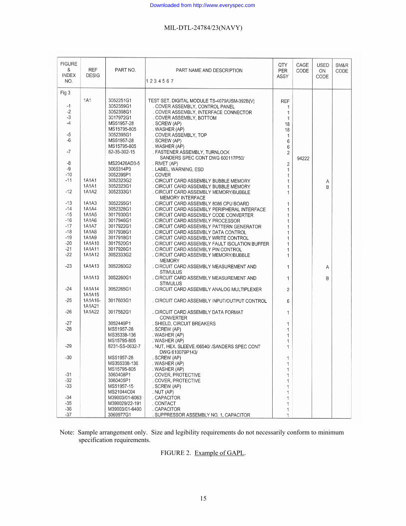
3.6.4 GAPL <gapl>. The GAPL (figure 2) shall be prepared as a tabular listing of all authorized repair parts for use in the performance of maintenance. Basic top-down breakdown sequence shall not be used in the development of the GAPL data, unless it matches the maintenance task to be performed. When used on codes are needed to reflect multiple applications of items in an individual GAPL, an explanation of the used on code shall be included in the IPB introduction. Additionally, a code list may be placed at the bottom of the last tabular page of an individual GAPL for codes used within that GAPL (for example, Effectivity used to indicate that the item is applicable only after or before incorporation of a technical directive and/or specific serial number application). Refer to 3.6.4.7 for used on code requirements. The GAPL entries are described in 3.6.2.1.
4
Downloaded from http://www.everyspec.com
MIL-DTL-24784/23(NAVY)
3.6.4.1 Index numbers. The index numbers that appear in the associated illustrations shall appear as an entry under the heading “FIGURE & INDEX NO.” in numerical sequence beginning with the number 1. Index numbers shall be assigned to all parts listed in the GAPL that have maintenance or supply significance, except as otherwise noted herein. Index numbers shall be first assigned to the GAPL and then applied to the IPB maintenance illustrations to maintain the proper sequence in the breakdown. If the same part number is listed more than once in the breakdown, it shall be assigned a different index number for each listing. No index number shall be assigned to an assembly when all detail parts are indexed, unless such assembly is also illustrated completely assembled on the illustration.
3.6.4.1.1 Index numbers for attaching parts.
a. Index numbers should be assigned to all attaching parts (or fastening groups). b. Fastening groups used at the same location (for example, a relay attached by multiple nuts, bolts, and
washers) need not be individually illustrated or identified by index number, unless maintenance significant. When group callouts are used, they shall contain only one particular size, combination, or group of parts. (1) Each size, combination, or group of parts shall be listed separately. (2) If an identical part, appearing at several locations, is attached with different attaching parts, the part
shall be indexed separately. (3) If more than one size or type of attaching part is used at different points on the part being attached,
each size (with the pertinent attaching parts such as washer and nut) shall be given a separate index number so that the location of the different sizes and types may be readily identified in the illustration.
3.6.4.2 Reference designations. Reference designations assigned to parts shall be listed and appear as an entry under the heading “REF DESIG”. The parts list shall be divided and arranged by major units in numerical sequence (for example, unit 1 with its parts shall precede unit 2 with its reference designations parts, and so forth).
3.6.4.3 Part numbers. All end items, repair parts, and items of support equipment provisioned for the applicable maintenance level support of the article shall be listed by part number. Part numbers assigned to the parts listed shall appear as an entry under the heading “PART NO”.
3.6.4.3.1 Parts to be listed. The following parts shall be listed:
a. Government standard parts. Government standard part numbers shall be listed in the “PART NO.” entry. The part number shall be complete, including prefixes and suffixes to the basic number. If more than one Government standard part number is listed on the contractor drawing specification for a single application, the preferred part number shall be listed.
b. Government standard items containing nonstandard detailed parts. Items covered by Government standard drawings, that contain repair parts that are not designated by Government detailed designed drawing numbers, shall be listed in organizational level manuals by the Government standard part number when the NSN is assigned to the Government standard item.
c. Altered or source-controlled items. If any Government standard or commercial item is altered, selected, or source controlled because of special fit, tolerance, weight, or reliability of performance, the part number of the activity responsible for the alteration, selection, or source control shall appear in the “PART NO.” entry. Repainting, reidentifying, or other insignificant operations shall not be considered alterations, selections, or source controls.
d. Contractor standard parts. Contractor standard part numbers shall only be listed when an NSN is not assigned to the contractor standard part.
e. Standard hardware provisioned for lowest level of maintenance usage. Standard hardware (such as bolts, studs, packing, hose clips, fasteners, clamps, resistors, capacitors, diodes, transistors, gaskets) shall be listed. Only the quantity required per assembly shall be listed.
f. Oversize and undersize parts. When oversize or undersize parts are required and furnished and they are neither interchangeable with, nor within allowable production tolerances of, the standard size part, they shall be listed by the part number specified in the contract drawing specification. A used on code note shall provide additional information.
5
Downloaded from http://www.everyspec.com
MIL-DTL-24784/23(NAVY)
g. Parts kits. When repair parts for the end item or for repairable units within the end item are to be supplied in the form of kits, a part number shall be assigned to each kit. The kit part number shall be placed last in the list of parts of the unit to which it applies and at the same indentation as the unit to which it applies. Contents of the kit shall be listed at one indent below the kit description and shall not be assigned index numbers. Separate illustrations for kits shall not be prepared.
h. Alternate parts. An alternate part is defined as a part that is used when a preferable part is not available. Alternate parts shall be listed below the preferred part. The specific relationship shall be identified in the GAPL “PART NAME AND DESCRIPTION” and “USED ON CODE” entries.
i. Equivalent parts. An equivalent part is defined as a part that is used interchangeably with one or more parts, none of which are preferable over the other. Equivalent parts shall be listed below the original part. The specific interchangeability shall be identified in the GAPL “USED ON CODE” entry.
j. Selected electronic components. If a component board contains detail part(s) which can be replaced from a selection of components of different values, the illustration shall show one part. The GAPL shall list the basic part number without the specific value. If the selection is to be made after test, a note shall appear after the description of the part, for example, “/Value determined at test/”.
k. Markings. Decals, metalcals, and vinyl film markings, such as those that provide instructions, which require replacement or must be requisitioned separately, are considered to be parts. The identifying drawing number for each marking shall appear in the “PART NO.” entry. Each marking identified shall also be illustrated.
l. Support equipment. When specified by the acquiring activity, support equipment shall be listed (see 6.2). (1) Support equipment items requiring breakdown. Breakdown of support equipment listed in support of
an end item shall be included when: (a) The support equipment is peculiar to support the end item. (b) Provisioning documentation dictates repair of the support equipment at the maintenance level
coverage of the end item. (c) A separate publication is not available or has not been authorized.
(2) Logistically non-repairable support equipment. An illustration, part number, description of the item and quantity per assembly shall be included.
3.6.4.3.2 Items without part numbers. The following items without part numbers shall be listed:
a. Parts, which have neither a part number nor a type and model number assigned, shall have a dash (-) placed in the “PART NO.” entry.
b. Hardware procurable from normal commercial sources that does not have a part number assigned shall be identified by the abbreviation “COML” in the “PART NO.” entry. Identifying information such as dimensions, material, and type shall be given after the description to enable replacement procurement from commercial sources.
3.6.4.3.3 Parts not to be listed. The following parts shall not be listed:
a. Assembly detail parts that are permanently joined together. Parts that lose their identity by being welded or joined to other pieces as a permanent unit. This does not include riveted items provisioned for the applicable maintenance level of the manual.
b. Items made from bulk stock. Items made from (raw) bulk stock such as lockwire, bonding braid, upholstery cloth, and friction tape.
c. Structural items. Structural items, which serve no purpose in description of parts relationship or specification of significant procured parts, except when required to maintain next higher assembly identity or to identify items having maintenance significance.
d. Detail parts for consumable items. Details of items that are considered for throw away.
6
Downloaded from http://www.everyspec.com
MIL-DTL-24784/23(NAVY)
e. Substitute item. A substitute item is an item, which possesses such functional and physical characteristics as to be capable of being exchanged for another under specific conditions or for particular applications and without alteration of the item itself or those adjoining it. Degradation of equipment performance will result when substitute items are used. Substitute items shall not be listed, unless authorized by the acquiring activity.
3.6.4.4 Part name and description. The name of the part and descriptive data to identify the parts of the equipment and aid in determining substitutes shall be listed as an entry under the heading “PART NAME AND DESCRIPTION”. Such information shall consist of the name, electrical or mechanical characteristics, and when applicable, attaching hardware. Common parts (for example, washers, springs, nuts, bolts, and so forth) shall be identified by physical characteristics (material, grade, series, specifications, and sufficient dimensions). Additional specific technical content requirements for parts description are as follows:
a. Indentions to show item relationship. The end item nomenclature shall not be indented and shall be flush with the left margin in the description. Parts that comprise the end item shall be listed using indentions to show next higher assembly relationship. Runover lines of nomenclature should be indented an additional indention from the first line of nomenclature. Indention shall be indicated by leaders (a series of periods or dots) with one leader equal to one indention. Indention to show end item to assembly, subassembly, and detailed part relationships shall be presented as shown in the following example: END ITEM (figure coverage) Runover line of nomenclature for End Item (figure coverage) . Detailed parts for End Item (figure coverage) . ASSEMBLY . Attaching parts for ASSEMBLY (AP) . . Detailed parts for ASSEMBLY . . SUBASSEMBLY . . Attaching parts for SUBASSEMBLY (AP) . . . Detailed parts for SUBASSEMBLY . . . SUB-SUBASSEMBLY . . . Attaching parts for SUB-SUBASSEMBLY (AP) . . . . Detailed parts for SUB-SUBASSEMBLY
b. Nomenclature consistency. Nomenclature of identical systems, subsystems, equipment, support equipment, components, and parts of the end item shall be consistent throughout the GAPL. The correct nomenclature shall be derived from one of the following sources (listed in the order of precedence): (1) Nomenclature on the drawing from which the item was manufactured. (2) “AN” nomenclature. (3) Nameplate nomenclature. (4) H6 assigned nomenclature.
c. Identifying noun and noun modifiers. The identifying noun should be the first word of the description. Nomenclature for the assembly/subassembly/part should be arranged with the noun name preceding the modifiers; for example, “Power Driven Rotary Vacuum Pump” should be listed as “Pump, Rotary, Vacuum Power Driven”. Modifiers shall be arranged in the sequence as necessary to indicate specifics such as function and location, and to maintain consistency of nomenclature. Modifiers shall be added to the description of parts as required to assure positive identification; for example: washer, flat and washer, lock. These modifiers need not appear on the preparing activity drawing. “AN” nomenclature should not be used as a main entry, but should be used as a subordinate; for example, “Mount, Antenna, Coupler, UHF, MT-1995/A, (34A1)” should be listed as “MT-1995/A UHF Antenna Coupler Mount (34A1)”.
d. Parts kits. When specified by the acquiring activity, parts kits shall be listed (see 6.2). (1) A statement indicating parts(s) availability shall be included after the description of the item or unit
for which the kit is supplied.
7
Downloaded from http://www.everyspec.com
MIL-DTL-24784/23(NAVY)
(2) The kit(s) part numbers shall be placed last in the list of parts of the unit to which it applies and at the same indentation as the unit to which it applies.
(3) Part kits shall be at the same indention as the unit to which it applies. (4) Kit contents shall be at one indent below the kit description. (5) Lists of supplemental kits shall follow the list of original kits in the same manner as prescribed herein.
e. Listing attaching parts. Attaching parts shall be listed beneath the item to be attached. They shall be listed, preceding any detailed parts of the item, at the same indention as the part they attach. The caption “(AP)” shall immediately follow the part name. Common attaching parts for multiple items shall be listed once with an expanded heading to indicate the commonality.
f. Specialty items. Parts that have specific symbol designations shall have that designation listed, bracketed in bold type, immediately after the part name. Examples of specialty items that must be designated are: (1) Nuclear hardness critical items (HCI), critical safety items (CSI), or observable critical items (OSI). (2) Electrostatic discharge (ESD) sensitive parts. (3) Items using liquid oxygen (LOX). (4) Magnetic control items (MAG).
g. Abbreviation “ASSY or INSTL”. If the item is an assembly or installation, the abbreviation “ASSY or INSTL,” as applicable, shall follow the noun.
h. Drawing modifiers. The identifying noun or “ASSY” or “INSTL” shall be followed by the modifiers included in the drawing title description, and, when applicable, modifiers such “upper,” “lower,” “inner,” “outer,” “front,” and “rear” shall follow.
i. Dimensions. Where units of measurement are the same, they shall not be repeated with each dimension, for example: “⅛by 21⁄32 inch.” A zero shall precede the decimal point of decimal values less than one, for example, “0.5”.
j. Capitalization. The entire description may be in upper case letters. As a minimum, the item name shall be in upper case letters and the first letter of the first word immediately following the item name, and the first letter of proper nouns shall be upper case.
k. Abbreviations. Abbreviations shall be held to a minimum. Abbreviations shall be in accordance with MIL-DTL-24784 and ASME Y14.38M. Abbreviations shall be consistent throughout the IPB.
l. Leaders. Leaders (a series of periods or dots) shall be used to join the description and the “QTY PER ASSY” column. When the description requires more than one line, leaders shall only be used on the first line.
m. Tolerances for electrical/electronic parts. Percentages or actual values or allowable tolerances for such items as nonmilitary standard resistors and capacitors shall be given as part of the description, expressed as plus and minus values.
n. Undrilled or untrimmed parts. Parts that require drilling or trimming on installation shall be identified by a notation to that effect in the description.
o. References to other manuals. If coverage of the end item is contained in another manual, the applicable end item shall be listed and reference made to the manual. The reference shall appear after the item description, in diagonals or parenthesis, for example: “/REFER TO SE105-AW-MMA-010 FOR BREAKDOWN/”.
p. References to other figures in the same manual or volumes of the manual. If coverage is contained in another figure, the applicable end item shall be listed and reference made to the figure number. The reference shall appear after the item description, in diagonals or parenthesis, for example: “/Refer to Figure 5 for breakdown/”.
q. Next higher assembly references. Necessary reference shall be made to other figures for next higher assemblies. The reference shall appear after the item description, in diagonals or parenthesis, for example: “/REFER TO FIG X FOR NHA/” or “(REFER TO SWXXX-XX-MMO-010 FOR NHA)”.
3.6.4.5 Quantity per assembly. The quantity required per assembly, per subassembly, and per sub-subassembly, as applicable, shall be listed as an entry under a heading “QTY PER ASSY”.
8
Downloaded from http://www.everyspec.com

MIL-DTL-24784/23(NAVY)
a. The entries under “QTY PER ASSY” shall be aligned with the first line of multiple-line descriptions. b. If more than one assembly is required, the total of such assemblies shall be indicated. c. For detailed or subassembly parts of a major assembly, the quantity required for one major assembly shall
be indicated. d. For oversize or undersize parts (for example, shims), the letters “AR” shall be placed in this column to
indicate “As Required”. e. For unspecified quantities (for example, wire, solder, etc.), the letters “AR” shall be placed in this column
to indicate, “As Required”. f. For items that are listed for reference, the letters “REF” (item found elsewhere in the IPB) shall be placed
in the column. g. Quantities of attaching parts shall be listed per unit (piece) only. For example, if two fittings are required
for each preceding assembly and one bolt is required to attach both fittings, the number 1 shall appear under “QTY PER ASSY” for the attaching bolt.
3.6.4.6 Commercial and government entity (CAGE) code. The original manufacturer’s CAGE identification code as listed in Catalog H4/H8 shall appear as an entry under the heading “CAGE CODE”.
3.6.4.7 Used on code. When required, used on codes for assemblies and parts to indicate their specific usability with the end item to which the IPB figure applies shall be listed as an entry under a heading “USED ON CODE.” Capital letters shall be used to identify the application of the items. If single letters of the alphabet are not sufficient to complete coding, double letters may be used, for example, AA, AB, etc. The letters O and I shall not be used singularly or in pairs. No used on code shall be used for assemblies and parts that are applicable to all end items.
a. Simple application. When different end item part numbers are identified, each end item shall be assigned a code in sequence and that code shall be listed for each peculiar item in the parts list. More than one code may be assigned to the same item, for example, A, B or A, C.
b. Redesigned parts. If the original part has continued application, the applicable model, block numbers, and serial numbers of the items on which the part is usable shall be indicated by used on codes.
c. Alternate parts. An alternate part is defined as a part that is used when a preferable part is not available. When an item is completely interchangeable but one part is preferable for use, the number of the preferred part shall be listed without a notation in the “USED ON CODE” entry and all alternate part numbers shall be listed with an asterisk (*) in the “USED ON CODE” entry. When an item is completely interchangeable on certain end items but one part number is preferable for use, the “USED ON CODE” entry shall carry the end item identification, with or without an asterisk (*), as applicable.
d. Equivalent parts. An equivalent part is defined as a part that is used interchangeably with one or more parts, none of which are preferable over the other. All equivalent part numbers shall be listed with an asterisk (*) in the “USED ON CODE” entry. When a part is interchangeable only on certain end items, the “USED ON CODE” entry shall carry the end item identification in addition to the required asterisk (*).
3.6.4.8 Source, maintenance, and recoverability (SM&R) code. When specified by the acquiring activity, the SM&R code assigned to the specific item/part shall be listed under the heading “SM&R CODE” (see 6.2).
3.6.4.9 Detailed IPB technical content requirements. General guidelines for IPB GAPL and illustration development shall be in accordance with 3.6.4 through 3.6.4.8. Additional detailed technical content requirements for GAPL and illustration development shall be in accordance with 3.6.4.9.1 through 3.6.4.9.7.
3.6.4.9.1 Index numbers on illustrations. Index numbers, with leader lines to the parts to which they pertain, shall be used on all IPB illustrations. Index numbers are assigned in accordance with 3.6.4.1. The index numbers on each illustration shall agree with those in the GAPL. Additional nomenclature may be added to these illustrations to properly identify parts not listed and indexed in the GAPL in order to properly indicate the relationship of parts to assemblies and to better present the maintenance procedures.
9
Downloaded from http://www.everyspec.com

MIL-DTL-24784/23(NAVY)
3.6.4.9.2 Attaching parts on illustrations. Each part in a set of attaching parts (such as bolt, washer, and nut) shall be assigned an index number. Sets of attaching parts shall be exploded when the assembly is hidden and sufficiently complex to merit explosion. The total quantity of each item listed in the GAPL shall be identified with index numbers in the illustration. To avoid cluttering an illustration with unnecessary index numbers, large quantity items need not be indexed more than once on the illustration or on each sheet of a multi-used illustration that the part is shown. However, the location of the items must be obvious in the illustration. For example, multiple size rivets that are shown in various locations on the illustration need only be indexed once for each part number listed in the GAPL.
3.6.4.9.3 Indexing assemblies. Each assembly and subassembly of the end item shall be shown assembled and assigned an index number. Assemblies and subassemblies coded for assembly, manufacture, or repair at the applicable maintenance level shall also be shown exploded in a detail view on the main illustration or in a separate illustration, and index numbers shall be assigned to all detailed parts.
3.6.4.9.4 Items not having a logical maintenance sequence. For items not having a logical maintenance sequence (for example, circuit card assembly), index numbers shall be assigned by beginning at the top left-hand corner and continuing clockwise.
3.6.4.9.5 Component boards. When a component board or bracket assembly that holds electrical components is presented orthographically (two dimensional), the reference designation may be placed within the view of the part, if space permits. Leader lines may be used to identify reference designations that cannot be placed within the view of the part. When the number of leader lines to indexed parts causes the illustration to become cluttered, the figure may contain a legend adjacent to the artwork or on a separate sheet. The legend shall contain an alphanumerical listing of the reference designations and their associated GAPL index numbers. Index numbers for items with reference designations shall be identified using the legend and not on the artwork.
3.6.4.9.6 Polarity identification. When applicable, the polarity of electronic components shall be identified on the component of all maintenance illustrations.
3.6.4.9.7 Reference designations. Illustrations that depict electrical components should include reference designation after the index number. If an orthographic view is prepared, the reference designation may be placed within the view of the part, if space permits.
3.6.5 Numerical index of part numbers <PartNoIndexIP>. All IPBs should have a numerical index (standard list) of part numbers (figure 3). The primary purpose of this index is to provide direct access to the specific manual, figure, and index number related to a specific part number. The numerical index of part numbers shall use the column heads “PART NUMBER” and “FIGURE/INDEX NUMBER” or “PUBLICATION/FIGURE/INDEX NUMBER”.
3.6.5.1 Development of the numerical index of part numbers. The numerical index should be prepared as follows:
a. Part number column. The part number column is used to establish the content. All part numbers listed in the GAPL part number column of every IPB figure contained in the manual should be listed. Superseded parts that have continued application should be listed. Government standard and attaching parts may be listed in the index only for their first appearance in the manual to reduce unnecessary redundant entries in the index. Part numbers for items listed more than once in the manual (except for Government standard and attaching parts) should have entries for each listing.
b. Figure/index number column. The diagonal line (/) is used to separate the entries. When more than one entry is required for a part number, the entries shall be listed in the following order of precedence: figure number and index number. When the entry is for the IPB figure’s end item, the index number should be left blank. Each entry shall list the figure number first, followed by a diagonal line, and the index number, for example, “1/17”.
10
Downloaded from http://www.everyspec.com

MIL-DTL-24784/23(NAVY)
c. Publication/figure/index number column (multi-volume TMs only). The publication number should be added to the figure and index number listing required by b, above (figure 4). A sufficient portion of the publication number of the manual/volume in which each part number listed appears should be identified. For example, if the first volume is numbered SE212-V9-MMO-010 and the second volume is numbered SE212-V9-MMO-020, only the numbers 010 and 020 would be listed. The method of identification should be explained in the applicable introduction. Each entry should list the publication number first, followed by a diagonal line, the figure number second, followed by a diagonal line, and the index number, for example, “Publication Number/Figure Number/Index Number (020/41/17)”.
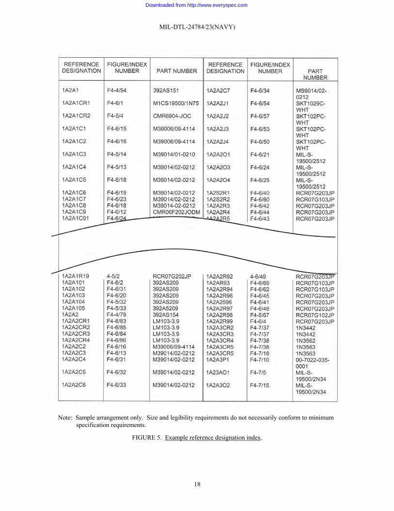
3.6.6 Reference designation index <RefDesIndexIP>. All IPBs containing any reference designations shall have a reference designation index (standard list) (figure 5). The primary purpose of this index is to provide direct access to the specific manual, figure, and index number related to a specific reference designation. The reference designation index shall consist of the following column heads:
a. The column heads “REFERENCE DESIGNATION” or “REF DES” and “FIGURE/INDEX NUMBER” or “PUBLICATION/FIGURE/INDEX NUMBER” shall be used.
b. Other column heads such as “USED ON CODE” may be added when required by the acquiring activity (see 6.2).
3.6.6.1 Development of the reference designation index. The reference designation index should be prepared as follows:
a. Reference designation column. When reference designations have been canceled for more than two consecutive items, only the first and last of the designations are to be listed, separated by the word “through”. For example: 3A1R69 through 3A1R100 not used. All reference designations identified in any IPB figure contained in the manual should be listed in reference designation sequence or in normal computer (ASCII code) ascending numeric/alpha, reference designation sequence.
b. Reference designation assignment. When reference designations for electronic equipment/components have not been assigned, reference designations shall be assigned as follows:
Unit 1 (Cabinet or equipment parts) 1AT1 1B1 1C1 1CR1 1R1 and so forth Assembly 1A1 (Assembly parts) 1A1AT1 1A1B1 1A1C1 1A1CR1 1A1R1 and so forth Subassembly 1A1A1 (Subassembly parts) 1A1A1AT1 1A1A1B1 1A1A1C1 1A1A1CR1 1A1A1R1 and so forth Unit 2 and so forth
11
Downloaded from http://www.everyspec.com
MIL-DTL-24784/23(NAVY)
c. Figure/index number column. The diagonal line (/) is used to separate the entries. When more than one entry is required for a reference designation, they should be listed in the following order of precedence: figure number and index number. When the entry is for the IPB figure’s end item, the index number should be left blank. Each entry should list the figure number first, followed by a diagonal line, and the index number, such as “41/17”.
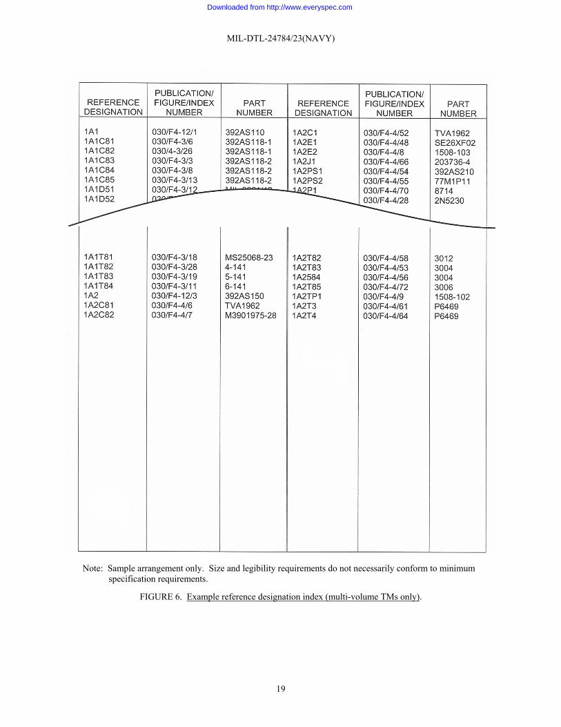
d. Publication/figure/index number column (multi-volume TMs only). The publication number should be added to the figure and index number listing required by c, above (figure 6). A sufficient portion of the publication number of the manual/volume in which each part number listed appears should be identified. For example, if the first volume is numbered SE212-V9-MMO-010 and the second volume is numbered SE212-V9-MMO-020 only the numbers 010 and 020 would be listed. The method of identification should be explained in the applicable introduction. Each entry should list the publication number first, followed by a diagonal line, the figure number second, followed by a diagonal line, and the index number, such as “Publication Number/Figure Number/Index Number (020/41/17)”.
e. Used on code column. This column may be added to the index if required for clarity; refer to 3.6.4.7. When added, the column must be added to all index pages. When figure-specific used on codes are used in different IPB figures, a modified coding must be used for this index.
3.6.7 List of manufacturers. The list of manufacturers shall contain the names, addresses, and CAGE code of all manufacturers supplying items for the equipment as referenced in the GAPL. The list shall be presented in numerical sequence by CAGE code. CAGE numbers shall be in accordance with Catalog H4/H8.
3.6.8 Additional indices. When specified by the acquiring activity, additional indices such as component listing, cable listing and part number to NSN index shall be prepared (see 6.2).
4. VERIFICATION
4.1 Verification. The verification requirements shall be in accordance with MIL-DTL-24784.
5. PACKAGING
5.1 Packaging. For acquisition purposes, the packaging requirements shall be as specified in the contract or order (see 6.2). When packaging of materiel is to be performed by DoD or in-house contractor personnel, these personnel need to contact the responsible packaging activity to ascertain packaging requirements. Packaging requirements are maintained by the Inventory Control Point’s packaging activities within the Military Service or Defense Agency, or within the military service’s system commands. Packaging data retrieval is available from the managing Military Department’s or Defense Agency’s automated packaging files, CD-ROM products, or by contacting the responsible packaging activity.
6. NOTES
(This section contains information of a general or explanatory nature that may be helpful, but is not mandatory.)
6.1 Intended use. The TMs or IPB data prepared to this specification are intended to be used for maintenance and parts support of systems and equipment. The TM should be used as a training document in the classroom and as a source for on-the-job training.
6.2 Acquisition requirements. Acquisition documents should specify the following:
a. Title, number, and date of the specification. b. Issues of documents to be cited in the solicitation (see 2.2 and 2.3). c. Type and quantity of development products to be delivered (see 3.2). d. Specify the maintenance coverage required (see 3.5). e. Specify if IPB shall be developed as a separate manual or as part of a maintenance manual (see 3.6). f. Specify if any additional indices shall be provided (see 3.6.a.8, 3.6.b.7, and 3.6.8). g. Specify if an explanation of SM&R codes with appropriate supporting illustrations shall be included (see
3.6.2.1h).
12
Downloaded from http://www.everyspec.com

MIL-DTL-24784/23(NAVY)
h. Specify if a description of the contents of any additional columns shall be included (see 3.6.2.1.i). i. Specify if support equipment shall be listed (see 3.6.4.3.1.l). j. Specify if parts kits shall be listed (see 3.6.4.4d). k. Specify if SM&R codes shall be listed in the GAPL (see 3.6.4.8). l. Specify if other columns are required in the reference designation index (see and 3.6.6.b). m. Specify packaging (see 5.1).
6.3 Technical manual acquisition. This specification (or a TMCR based on this specification) must be listed on the Contract Data Requirements List (DD Form 1423) in order to acquire the TMs described by this specification. An alternate acquisition strategy should be devised by contracting officers for those solicitations or contracts which are exempted from using the Uniform Contract Line Item Numbering System (UCLINS).
6.4 Definitions. The words or phrases used throughout this specification are defined in MIL-DTL-24784.
6.5 Subject term (key word) listing.
Group assembly parts list Numerical index of part numbers Reference designation index
13
Downloaded from http://www.everyspec.com

MIL-DTL-24784/23(NAVY)
Note: Sample arrangement only. Size and legibility requirements do not necessarily conform to minimum specification requirements.
FIGURE 1. Exploded view example of IPB illustration.
14
Downloaded from http://www.everyspec.com
MIL-DTL-24784/23(NAVY)
Note: Sample arrangement only. Size and legibility requirements do not necessarily conform to minimum specification requirements.
FIGURE 2. Example of GAPL.
15
Downloaded from http://www.everyspec.com

MIL-DTL-24784/23(NAVY)
Note: Sample arrangement only. Size and legibility requirements do not necessarily conform to minimum specification requirements.
FIGURE 3. Example numerical index of parts.
16
Downloaded from http://www.everyspec.com

MIL-DTL-24784/23(NAVY)
Note: Sample arrangement only. Size and legibility requirements do not necessarily conform to minimum specification requirements.
FIGURE 4. Example numerical index of parts (multi-volume TMs only).
17
Downloaded from http://www.everyspec.com
MIL-DTL-24784/23(NAVY)
Note: Sample arrangement only. Size and legibility requirements do not necessarily conform to minimum specification requirements.
FIGURE 5. Example reference designation index.
18
Downloaded from http://www.everyspec.com
MIL-DTL-24784/23(NAVY)
Note: Sample arrangement only. Size and legibility requirements do not necessarily conform to minimum specification requirements.
FIGURE 6. Example reference designation index (multi-volume TMs only).
19
Downloaded from http://www.everyspec.com

MIL-DTL-24784/23(NAVY)
20
Custodian: Preparing Activity:
Navy – SH Navy – SH (Project TMSS-N256-000)
Review Activity: Navy – EC
NOTE: The activities listed above were interested in this document as of the date of this document. Since organizations and responsibilities can change, you should verify the currency of the information above using the ASSIST Online database at http://assist.daps.dla.mil.
Downloaded from http://www.everyspec.com