includes - fontaine fifth...
TRANSCRIPT

800-874-9780 • www.fifthwheel.com 800-874-9780 • www.fifthwheel.com Sec A: 1
6000/7000/7000C top plates
Includes:• Identify your fifth wheel • Pre-service procedures • Preventive maintenance • Troubleshooting • Rebuild information• Mounting information• Frequently asked questions• Supplemental videos available at www.fifthwheel.com
LT-143©Copyright 2016 • Fontaine Parts Connection
Section A: Fontaine No-Slack® 7000CC, 7000 & 6000
Section B: Fontaine No-Slack® 5092
Section C: Fontaine 3000 Series
Section D: Mounting information
Section E: Frequently asked questions

800-874-9780 • www.fifthwheel.com 800-874-9780 • www.fifthwheel.com Sec A: 1
6000/7000/7000C top plates
Contents
No-Slack
Identify fifth wheel assembly
Identify top plate
Identify slides and brackets (Note: see Slides and Bracket section for more information)
6000 SeriesStamped Steel
No-Slack® ®
7000 SeriesCast SteelNo-Slack
®
™7000CC Series
Clean ConnectCast SteelNo-Slack
ATB
PSA PMAPLA
A36 FMABSM
AWB MTB
Identify your fifth wheel .............................Sec A: 1-2Pre-service procedures ..............................Sec A: 3-5Preventive maintenance .............................Sec A: 6-9Troubleshooting .....................................Sec A: 10-15Rebuild ..................................................Sec A: 16-23
Sec A: 2
6000
/700
0/70
00C
top
plat
es
Identify your fifth wheel
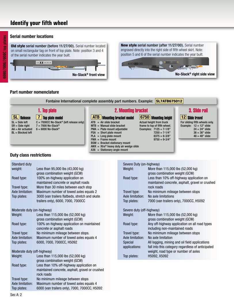
SL 7 ATB 6750 12Release Top plate model Mounting bracket model Mounting height Slide travel
1. Top plate 2. Mounting bracket 3. Slide rail
Fontaine International complete assembly part numbers. Example: SL7ATB675012
SL = Side left SR = Side rightAA = Air actuatedBL = Blocked left
C = 7000CC No-Slack® (left release only) 7 = 7000 No-Slack®
6 = 6000 No-Slack®
Actual height from truck frame to top of fifth wheel.Examples: 7125 = 7-1/8" 7250 = 7-1/4" 8375 = 8-3/8" 9750 = 9-3/4"
For sliding fifth wheels only. Example: 12 = 12" slide 24 = 24" slide 36 = 36" slide 48 = 48" slide
ATB = Air slide bracketMTB = Manual slide bracketPMA = Plate mount adjustablePSA = Short plate mountPLA = Long plate mountFMA = Frame mountBSM = Bracket stationary mountAWX = Xtra® heavy duty air wedge slideA36 = Stationary angle mount
Serial number locations
Part number nomenclature
Duty class restrictions
New style serial number (after 11/27/00). Serial number engraved directly into the right side of fifth wheel skirt. Note: position 5 and 6 of the serial number indicates the year built.
XXXXXXXXX
No-Slack® right side view
Old style serial number (before 11/27/00). Serial number located on small rectangular tag on front of top plate. Note: position 3 and 4 of the serial number indicates the year built.
XXXXXXXXX
No-Slack® front view
Standard duty weight: Less than 95,000 lbs (43,000 kg) gross combination weight (GCW)Road type: 100% on-highway application on maintained concrete or asphalt roadsTravel type: More than 30 miles between each stopAxle limitation: Maximum number of towed axles equals 2Top plates: 3000 (van trailers flatbeds, stretch and skate trailers only), 6000, 7000, 7000CC
Moderate duty (on-highway) Weight: Less than 115,000 lbs (52,000 kg) gross combination weight (GCW)Road type: 100% on-highway application on maintained concrete or asphalt roadsTravel type: No minimum mileage between stops.Axle limitation: Maximum number of towed axles equals 4 Top plates: 6000, 7000, 7000CC, H5092
Moderate duty (off-highway) Weight: Less than 115,000 lbs (52,000 kg) gross combination weight (GCW)Road type: Less than 10% off-highway application on maintained concrete, asphalt, gravel or crushed rock roadsTravel type: No minimum mileage between stopsAxle limitation: Maximum number of towed axles equals 4 Top plates: 6000 (van trailers only), 7000, 7000CC, H5092
Severe Duty (on-highway) Weight: More than 115,000 lbs (52,000 kg) gross combination weight (GCW)Road type: Less than 10% off-highway application on maintained concrete, asphalt, gravel or crushed rock roadsTravel type: No minimum mileage between stopsAxle limitation: No axle limitations Top plates: 7000 (van trailers only), 7000CC, H5092
Severe duty (off-highway) Weight: More than 115,000 lbs (52,000 kg) gross combination weight (GCW)Road type: Any off-highway application on all road types including non-maintained roadsTravel type: No minimum mileage between stopsAxle limitation: No axle limitationSpecial All logging, mining and oil field applications applications: fall into this category regardless of anticipated weight, road type or number of axles Top plates: H5092, X5092

800-874-9780 • www.fifthwheel.com Sec A: 3
6000/7000/7000C top plates
Pre-service procedures
A. Check fasteners
Make sure all nuts and bolts are in place and properly tightened.
Check to see if both bracket pins are in place and secured by retainer pins and cotter pins.
See No-Slack® Pre-Service Deliver and Inspection video at www.fifthwheel.com ... click on Videos button
B. Lubricate fifth wheel.
Lubricate the fifth wheel prior to opening and closing.
Pre-service lubrication
1. On models WITHOUT bracker liners lift the top plate forward (front of the fifth wheel down) and apply grease to each bearing area through the zerk fitting (No-Slack® has two fittings each side) located on each side of the top plate just to the front of the bracket pins. Continue to apply grease until it is coming out of the back of the bearing. It may be necessary to raise the rear of the fifth wheel with a pry bar to open up the pocket slightly and allow the grease to flow through.
A substantial amount of grease may be required initially to fill the reservoir. Tilt the wheel to the rear (rear of the wheel down) and repeat the procedure. Rock the top plate back and forth several times to spread the grease over the bearing surface.
Inspect the trailer kingpin plate and top surface of the fifth wheel to make sure each is properly greased. A liberal coating of grease should be applied to the complete surfaces of both the trailer kingpin plate and the top surface of the fifth wheel. A paddle or brush will make this job easier.
Do not use a lube plate (high-density polyethylene) on top of the fifth wheel or on the kingpin in lieu of grease without prior approval by Fontaine International. The additional thickness of this material can prevent the proper operation of the fifth wheel and can cause a dangerous condition.
Bracket pinRetainer pin
Cotter pin
No-Slack® II fifth wheel
Grease the mount brackets (4 zerks). Lift the top plate up with a pry bar to ensure grease gets to the top of the brackets. If your model features bracket liners skip this step, but check for free rocking motion.
Grease all zerks (both
sides
Pry up top plate for best
results

800-874-9780 • www.fifthwheel.comSec A: 4
6000
/700
0/70
00C
top
plat
es C. Operation
1. Manual model: Fontaine’s No-Slack® 7000 and 6000 series fifth wheel shown in Figure 1 opens by a straight pull on the release handle which releases the secondary lock automatically as the mechanism opens.
2. Air actuated model: Fontaine’s air actuated No-Slack® air-actuated fifth wheel is shown below. They open with a release valve located on the dash or in a lock box mounted on the rear of the cab. To open, set the tractor parking brake and pull the release valve. Hold the valve open until the locking mechanism is locked in the open position. The pull valve will not activate the air cylinder unless the tractor parking brakes are set.
3. Close the locking mechanism using a test kingpin or 2" diameter pipe. Repeat several times making sure that all moving parts have adequate lubrication.
4. The pull handle should always be free of grease or any substance which could prevent a firm grip, causing the handle to slip and resulting in injury.
2. Lubricate the fifth wheel prior to opening and closing. Referring to jaw and wedge photo below, grease the jaw and wedge on top and bottom. Separate the jaw and wedge with a large screwdriver and distribute the grease along the full length of the jaw and wedge mating surfaces. Open and close the fifth wheel several times to further distribute the grease.
Fontaine suggests the use of a moly based lubricant such as Mobilgrease XHP320 or equivalent when applying lubricant to the locking jaw and wedge.
Lightly oil other moving parts in the fifth wheel.
3. For sliding fifth wheels, lightly oil the locking mechanism. Operate the mechanism (air or manual) several times to ensure it is functioning properly.
4. Grease the top plate. Spread grease all over the mating surface of the top plate. Be sure the grease pockets built into the top plates are full of grease.
Pre-service procedures
Spring on manual models
Pull handle
Air cylinder on air actuated models
Prior to greasing jaw and wedge in step 2, trip the locking mechanism with a pry bar by pushing the bumper off its seat. Keep your hands and arms out of the fifth wheel throat.
Bumper
Separate the jaw and wedge with a screwdriver and press a moly based lubricant between the serrated surfaces (moly-based lubricant such as Mobilgrease XHP320 or equivalent). Also press the lubricant in the kingpin contact area on both the stationary jaw and the moveable jaw. Work the action of the pull handle back and forth to spread the lube over all the surfaces.
Kingpin Contact Area
Jaw
Wedge
800-874-9780 • www.fifthwheel.com 800-874-9780 • www.fifthwheel.com Sec A: 5
6000/7000/7000C top plates
Pre-service procedures
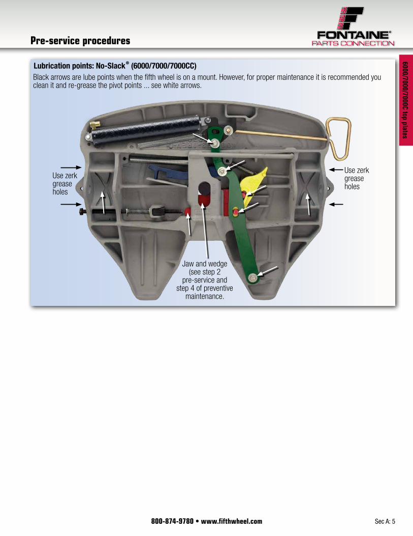
Black arrows are lube points when the fifth wheel is on a mount. However, for proper maintenance it is recommended you clean it and re-grease the pivot points ... see white arrows.
Lubrication points: No-Slack® (6000/7000/7000CC)
Jaw and wedge (see step 2
pre-service and step 4 of preventive
maintenance.
Use zerk grease holes
Use zerk grease holes

800-874-9780 • www.fifthwheel.comSec A: 6
6000
/700
0/70
00C
top
plat
es
Fontaine International’s preventive maintenance procedures for No-Slack fifth wheels.
This section covers the recommended steps for performing the 90 day / 30,000 mile PM and includes Visual Inspection, Function, Wedge-stop Rod Adjustment and Lubrication.
Remember to exercise extreme caution, follow all stated & customary safety procedures, and be sure to wear safety glasses.
Look under the fifth wheel and make sure that nothing is hanging loose.
Check and make sure the bracket pins on both sides of the fifth wheel are in place and secured by retainer pins and cotter pins.
Step 1. Visual inspection
Begin the visual inspection by cleaning the fifth wheel. To degrease properly, the lock should be in the closed position. To close the lock, push the bumper off its seat with a pry bar. This provides cleaning access to the jaw and wedge.
Be careful. When the mechanism closes, the handle moves in quickly.
After cleaning, check the top plate, mounting brackets, mounting angles and all moving parts for cracks, excessive wear, loose or missing bolts or any other damage. Check for securely fastened and properly working springs.
To close the lock push the bumper off its seat with a pry bar.
Bumper
Preventive maintenance
See No-Slack® Preventive Maintenance video at www.fifthwheel.com ... Click on Videos button

800-874-9780 • www.fifthwheel.com 800-874-9780 • www.fifthwheel.com Sec A: 7
6000/7000/7000C top plates
Step 2: Function inspection
Begin with the fifth wheel in the unlocked position. Pull handle to unlock fifth wheel if it is not open.
Insert a test kingpin, such as Fontaine Kingpin Tool MSC-712, to close the lock.
Only minimal force is required to couple your Fontaine fifth wheel.
Make sure the jaw and wedge are engaged behind the kingpin and the pull handle is fully retracted. In the locked position, the pull handle should be within one inch of the skirt of the wheel.
Open and close the wheel again. Look for a quick, crisp closing action.
If the action is slow or sluggish, it may be due to a build up of old grease or a bent part causing binding (see trouble shooting section)
On air slide models activate air slide cylinder from the cab and check for proper operation and leaks.
Lightly lubricate the pivot points on the mechanism with a spray lubricant.
Be sure switch is in the locked position and the locking members are fully extended (locked) into the slide rail on both sides before the truck leaves the shop!
Step 3: Adjustment
Adjust the wedge-stop rod
With the wheel still closed on the kingpin tool, push on the wedge- stop rod until it touches the end of the wedge and let it spring back. (the wedge-stop rod is spring-loaded and should spring back out after you push it in).
This movement or free play should be one quarter of an inch when coupled to a 2" kingpin.
To adjust, turn the wedge-stop rod counter clockwise to increase the free travel or clockwise to reduce free travel. Turning it in too far will result in slack and cause premature wear, but any mis-adjustment can cause the fifth wheel to bind and become hard to open.
Close with 2" kingpin
or shaft
Wedge-stop rod
1/4" Gap
Wedge
Preventive maintenance
Wedge in closed position
Handle closed within 1"
Illustration shows proper gap. Only measure when fifth wheel is in closed position using 2" kingpin or shaft.
Verify that the pull handle is in fully locked position (within 1" of the fifth wheel skirt.

800-874-9780 • www.fifthwheel.comSec A: 8
6000
/700
0/70
00C
top
plat
es Step 4: Lubrication
On models WITHOUT bracket liners, apply grease to the two zerk fittings on each side of the top plate. These supply lubricant to the bracket bearings. Bearings should be greased with the fifth wheel in an unloaded condition.
Rock the wheel back and forth while applying grease.
Some grease should flow from the bearing pockets.
If you do not see grease coming from the bearing pocket, use a crow bar to lift the top plate while applying grease.
On models WITH bracket liners, it is not necessary to lubricate the fittings on each
side of the top plate, but free rocking motion is important. If the fifth wheel does NOT rock freely, remove the top plate to inspect the liners. Initial inspection of the bracket liners should be made at 200,000 miles and every 100,000 miles there after. If necessary see bracket liner inspection and installation on next page.
All models require the remaining lubrication steps. First trip the wheel closed by pushing the bumper off its seat with a pry bar. Be careful. When the mechanism closes, the handle moves in quickly.
Next, pull back slightly on the pull handle, separate the jaw and wedge with a big screw driver, and distribute grease between the jaw and wedge pressing it between the serrated surfaces. Fontaine recommends a moly based lubricant such as Mobilegrease XHP320 or equivalent.
Also apply grease to the stationary jaw at the front of the throat.
Now, work the lock mechanism back and forth several times to further distribute the grease.
Now lubricate the secondary lock and any other pivot points under the fifth wheel with a spray lube. See lubrication points on page A:5.
Grease the mount brackets (4 zerks). Lift the top plate up with a pry bar to ensure grease gets to the top of the brackets.
Hint: if the zerks will not take grease, remove top plate and clear the grease channels.
Grease all zerks (both
sides)
Grease channels
Pry up top plate for best
results
Prior to greasing jaw and wedge trip the locking mechanism with a pry bar by pushing the bumper off its seat. Keep your hands and arms out of the fifth wheel throat.
Bumper
Kingpin contact area
Jaw
Wedge
Preventive maintenance

800-874-9780 • www.fifthwheel.com 800-874-9780 • www.fifthwheel.com Sec A: 9
6000/7000/7000C top plates
Now lubricate the top of the fifth wheel.
A liberal coating of grease should be applied to the top surface of the fifth wheel. A wide putty knife or brush will make this job easier.
Apply liberal amounts of grease to the entire surface of the fifth wheel making sure the grease grooves in the surface are full of new grease.
You have now completed Fontaine’s recommended 90 day / 30,000 mile preventive maintenance and your truck is ready to be returned to service.
Preventive maintenance
Bracket liner inspection and replacement
Inspection criteria:
1. Initial inspection of bracket liners should be made at 200,000 miles and every 100,000 miles there after.
2. Bracket liners should be replaced when liner thickness measures 0.125" or less. Measurement should be made at the thinnest point of the bracket liner. This is typically at the top portion of the liner.
Installation instructions:
Removal of a bracket liner:
1. Remove fifth wheel from the mounting bracket. Fifth wheel removal includes:
a. Removing cotter pins from the retainer pins b. Removing the retainer pins c. Removing the bracket pins
from the fifth wheel d. Remove fifth wheel from
mounting bracket2. Using a flat head screwdriver, pry –
with an upward force – on the end of the bracket liner. Bracket liner should release from the mounting bracket.
Installation of a new bracket liner:
1. Place the new bracket liner directly over the mounting bracket.2. Using a rubber mallet, strike the top of the bracket liner. The new
bracket liner should lock into place.3. Once both new liners are installed, reinstall the fifth wheel onto the
mounting bracket.4. Insert the bracket pins back into the fifth wheel (Note: placing some
grease on the end of each bracket pin is recommended). Reinstall the retainer pin and cotter pins.
5. Tilt the fifth wheel to the front and back of the mounting bracket to ensure that the bracket liners are properly installed.
.125" Minimum
Part Number LNR-BKT-107
Strike with rubber mallet herePlace bracket liner over mounting bracket
Place flat head screwdriver here

800-874-9780 • www.fifthwheel.comSec A: 10
6000
/700
0/70
00C
top
plat
es
Troubleshooting
Slack
1. Check your pull handle.• If it is bent replace it.2. Check your adjustment.
With the wheel still closed on the kingpin tool, push on the wedge-stop rod until it touches the end of the wedge and let it spring back. (the wedge-stop rod is spring-loaded and should spring back out after you push it in).
This movement or free play should be one quarter of an inch when coupled to a 2" kingpin.
To adjust, turn the wedge-stop rod counter clockwise to increase the free travel or clockwise to reduce free travel. Turning it in too far will result in slack and cause premature wear, but any mis-adjustment can cause the fifth wheel to bind and become very hard to open.
Close with 2" kingpin
or shaft
Wedge-stop rod
1/4" Gap
Wedge
Handle closed within 1"
Illustration shows proper gap. Only measure when fifth wheel is in closed position using 2" kingpin or shaft.
Verify that the pull handle is in fully locked position (within 1" of the fifth wheel skirt.
3. Check the serrations between the jaw and wedge.Close the wheel by using a long pry bar. Separate the jaw and wedge using a flat head screw driver. Run the screw driver be-tween the jaw and wedge to feel serrations. If the serrations are smooth the fifth wheel needs to be rebuilt (see rebuild instructions).
If serrations are not worn grease jaw and wedge. First trip the wheel closed by pushing the bumper off its seat with a pry bar. Be careful. When the mechanism closes, the handle moves in quickly.
Next, pull back slightly on the pull handle, separate the jaw and wedge with a big screw driver, and distribute grease between the
Prior to greasing jaw and wedge trip the locking mechanism with a pry bar by pushing the bumper off its seat. Keep your hands and arms out of the fifth wheel throat.
Bumper
Serrations
Kingpin contact area
Jaw
Wedge

800-874-9780 • www.fifthwheel.com 800-874-9780 • www.fifthwheel.com Sec A: 11
6000/7000/7000C top plates
Troubleshooting
jaw and wedge pressing it between the serrated surfaces. Fontaine recommends a moly based lubricant such as Mobilegrease XHP320 or equivalent.
Also apply grease to the stationary jaw at the front of the throat.
Now, work the lock mechanism back and forth several times to further distribute the grease.
Now lubricate the secondary lock and any other pivot points under the fifth wheel with a spray lube. See lubrication points on page A:5.
4. Check your trailer kingpin using a Fontaine kingpin gauge MSC-GAUGE
• If the kingpin is worn out replace it (see SAEJ2228).
Hard to open1. All pressure must be removed from
the lock before it will open.2. Check the pull handle.If the pull handle is bent replace it.3. Check for proper lubricationFirst trip the wheel closed by pushing the bumper off its seat with a pry bar. Be careful. When the mechanism closes, the handle moves in quickly.
Next, pull back slightly on the pull handle, separate the jaw and wedge with a big screw driver, and distribute grease between the jaw and wedge pressing it between the serrated surfaces. Fontaine recommends a Moly based lubricant such as Mobilegrease XHP320 or equivalent.
Also apply grease to the stationary jaw at the front of the throat.
Now, work the lock mechanism back and forth several times to further distribute the grease.
Now lubricate the secondary lock and any other pivot points under the fifth wheel with a spray lube. See lubrication points on page A:5.
Prior to greasing jaw and wedge trip the locking mechanism with a pry bar by pushing the bumper off its seat. Keep your hands and arms out of the fifth wheel throat.
Bumper
Kingpin Contact Area
Jaw
Wedge

800-874-9780 • www.fifthwheel.comSec A: 12
6000
/700
0/70
00C
top
plat
es
6. Kingpin gaugeMSC-GAUGE
Hard to close1. Check the bumper. With the fifth wheel in the open position check the upper tip of
the bumper. If the bumper is damaged replace it.2. Check the bumper and secondary lock springs. Replace springs if damaged.
3. Close the fifth wheel using your test kingpin. If the fifth wheel closes refer the driver to the proper Cupling procedure guide (LT-071) and the Fontaine International instructions book-let (LT-001).
4. Check the bottom flange of the kingpin for damage. You can use a Fontaine kingpin gauge MSC-GAUGE • If the kingpin is worn out replace it (see SAEJ2228).
4. Check adjustment on wheels with wedge-stop rod.
With the wheel still closed on the kingpin tool, push on the wedge-stop rod until it touches the end of the wedge and let it spring back. (the wedge-stop rod is spring-loaded and should spring back out after you push it in).
This movement or free play should be one quarter of an inch when coupled to a 2" kingpin.
To adjust, turn the wedge-stop rod counter clockwise to increase the free travel or clockwise to reduce free travel. Turning it in too far will result in slack and cause premature wear, but any mis-adjustment can cause the fifth wheel to bind and become hard to open.
5. Check the trailers kingpin using Fontaine kingpin gauge MSC-GAUGE.
• If the kingpin is worn out replace it (see SAEJ2228).
BumperTip
Secondary lock spring Bumper spring
1. Bumper
Close with 2" kingpin
or shaft
Wedge-stop rod
1/4" Gap
Handle closed within 1"
6. Kingpin gaugeMSC-GAUGE
Troubleshooting

800-874-9780 • www.fifthwheel.com 800-874-9780 • www.fifthwheel.com Sec A: 13
6000/7000/7000C top plates
Cold weather hints
Separate jaw and wedge with screw driver and grease full length.
Clean, oil and grease all moving parts (see arrows).
Wedge
Jaw
No-Slack® (6000/7000/7000CC)
Jaw and wedge
Grease fittings
When the temperature drops below freezing, Fontaine recommends a thorough cleaning of the latching mechanism using a suitable cleaner or degreaser. Lubricate the fifth wheel prior to opening and closing. Refer to figures below. Open and close the fifth wheel several times to distribute the grease. Fontaine suggests the use of a moly-based lubricant such as Mobilgrease XHP320 or equivalent. Areas or regions that experience extreme and/or prolonged freezing temperatures should consider using a less viscous substance such as: 90-weight oil, diesel fuel, kerosene, motor oil, etc. Fontaine recommends contacting your specific lubricant manufacturer for guidelines on mixing compatibility of any lubricant.
Kingpin contact areaKingpin contact areaKingpin contact area
Troubleshooting

800-874-9780 • www.fifthwheel.comSec A: 14
6000
/700
0/70
00C
top
plat
es
Hard to close 6000/7000/7000CC
Excessive slack6000/7000/7000CC
Hit the wedge-stop rod
Adjust the wedge-stop rod
Hard to open 6000/7000/7000CC
Are frontrocker limit blocks
installed?
Whencoupled is the gap
between the wedge-stop rod and the locking wedge 1/4"?
Will thepull handle move
more than 1 inch?
Have youhit the wedge-stop rod
to loosen it?
Are front rocker limit blocks
installed?
Engage trailer brakes and back up tractor to relieve pressure.
Make sure air suspension is not dumped before uncoupling.
Make sure bushings are not over-tightened.
Check for bent or damaged handle guide, pull handle, operating handle, cover plate.
Check serrations for proper fit, paint runs, or proper lubrication.
If wheel is air actuated, check for bent air cylinder shaft.
Check for obstruction hitting underneath.
Check for damage to wedge (burrs, bent from hitting kingpin, etc).
Check for proper wedge-stop rod adjustment.
Check for installation of correct bracket pins.
Check for proper installationof bushings.
Check for damage to locking mechanism, operating handle, pull handle, handle guide, cover plate, etc.
Check for damage to locking mechanism, operating handle,
pull handle, handle guide, cover plate, etc.
Check for interference between top plate and
base mount.
Adjust wedge-stop rod.Adjust wedge-stop rod.
Check for kingpin wear.
Check locking jaw and wedge serrations for wear.
Check stationary jaw for excessive wear or damage.
Check for bent operating handle and/or pull handle.
Check for bent handle guide and/or cover plate.
Check for bent or broken bumper guide.
Check for bent or damaged bumper and/or secondary
lock springs.
Check for missing pivot point bushings.
Check the tip of the bumper to make sure it isn't worn, broken or bent.
Check the bottom flange of kingpin to make sure it isn't worn, broken or bent.
Check to make sure the bumper spring and pull handle spring are not
missing or damaged.
Check the stationary jaw to make sure that it is positioned properly and that it
isn't worn, broken or bent.
Check the cover plate to make sure it is positioned properly and that it isn't
worn, broken or bent.
While coupling, does the
handle retract at all?
Is the fifth wheel lock
completely closed?
Check for damage to locking mechanism, operating handle,
pull handle, handle guide, cover plate, etc.
If wheel is air actuated, check for bent air cylinder shaft.
Check for damaged components such
as pull handle, operating handle,
handle guide. Install rocker limit blocks.
Finish or call Fontaine Parts Connection.
Finish or call Fontaine Parts Connection.
Finish or call Fontaine Parts Connection.
YES NO
NO
NO
YES
YES
NO
YES
YES YESNO NO
YES
NO
Troubleshooting

800-874-9780 • www.fifthwheel.com 800-874-9780 • www.fifthwheel.com Sec A: 15
6000/7000/7000C top plates
Will not latch open 6000/7000/7000CC
Air actuated coupling problems6000/7000/7000CC
Check for interference between top plate and base
mount.
Check for installation of correct bracket pins.
Check air supply line for damage (crushed or crimped).
Check air cylinderfor leakage.Check air cylinder
for leakage.
Check to see if air cylinder is installed properly.Check to see if air cylinder is
installed properly.
Replace bumper and handle spring with SPR-374.
Replace air line.
Check air cylinder port and/or relief valve hole for
obstruction.
Check for missing or damaged bumper springs.
Check for bent or damaged handle guide, pull handle, operating handle,
cover plate.
Check for worn/brokenor missing stationary jaw
or trailer kingpin.
Check tip of bumper hookfor wear, mushrooming
or broken tip.
Check for proper orientation ofpull handle andbumper latch.
Make sure secondary lock latch 1/2" pin is not missing
or damaged.
Have you checked for inter-
ference between wheel & base mount?
Is the fifth wheel closing
properly?
Is air supply line crushed or
crimped?
Detachair cylinder
from secondarylock, does thewheel open &latch properly
without air cylinder?
Detachair cylinder
from secondarylock, does thewheel open &latch properly
without air cylinder
Finish or call Fontaine Parts Connection.
Finish or call Fontaine Parts Connection.
Finish or call Fontaine Parts Connection.
YES
YESYES
YES
NO
NONO
NO NO
Go to"hard to open" on previous or "will not latch" at leftfor 6000/7000.
Go to"hard to open"
for 6000/7000 series on previous page.
Troubleshooting

800-874-9780 • www.fifthwheel.comSec A: 16
6000
/700
0/70
00C
top
plat
es
Rebuild
Note: rebuild only after checking the serrations for wear.
Inspect fifth wheel and cover plate and stationary jaw for damage (examples below).
Before rebuilding check to make sure that there are no cracks in the cross members or other components. Under no circumstances should a fifth wheel be repaired or used if any component (cross member, saddle bearing, etc). is cracked. Also check for excessively worn areas.
Serrations
See No-Slack® Rebuild Procedures video at www.fifthwheel.com ... Click on Videos button
Damage from high pin attempt
Damage from high pin attempt
Damage from high pin attempt
Damage from high pin attempt
Damage from high pin attempt

800-874-9780 • www.fifthwheel.com 800-874-9780 • www.fifthwheel.com Sec A: 17
6000/7000/7000C top plates
Rebuild
Items needed for rebuild (follow rebuild instructions included in the KIT-RPR-6000L)
Remember to exercise extreme caution, follow all stated & customary safety procedures, and be sure to wear safety glasses.
Do not use pneumatic tools. Over-tightening may cause damage.
• ¾” wrench • ¾” socket wrench • 1 1/16” wrench• Pliers • Flat head screw driver• Long pry bar• Test kingpin MSC-712• Kingpin gauge MSC-GAUGE• Moly-based lubricant such as Mobilgrease XHP320 or
equivalent
After inspection you may need to optionally order other kits. See schematic on page A:19.
Top plate rebuild kitNo-Slack rebuild kits for 6000/7000/7000CC top platesKIT-RPR-6000L (left release)KIT-RPR-6000R (right release)
Special tools
Kingpin gaugeMSC-GAUGE
Test kingpin for allFontaine fifth wheels
MSC-712
Fontaine offers special tools for your fifth wheel to help your repairs go fast and easy.
1/2" diameter holes
17-3/8"
You can upgrade your Fontaine 6000 or 7000 series fifth wheel from manual to "Air Actuated" in-cab release. Simply order a KIT-AA-6000L (road side release) or KIT-AA-6000R (curb side release). You will also need KIT-AIR-DASH for the parts required to complete the in-dash installation.
KIT-AIR-DASH
KIT-AA-6000L or R
Air actuated in-cab release

800-874-9780 • www.fifthwheel.comSec A: 18
6000
/700
0/70
00C
top
plat
es
Rebuild
Pull handleFront cross member
Bumper spring
Bearing pocket
Secondary safety lock
Wedge-stop rod spring
Wedge-stop rod
Wedge-stop rod nut
Rear cross member
bumper
Operating handle
Timer guide
Handleguide
Handlespring
Wedge
Timer spring
Timer
Stationary jawStepjaw
Jawguide
Supportguide
No-Slack® part identification (Note: 6000 is shown, but CC7000 and 7000 use same parts.

800-874-9780 • www.fifthwheel.com 800-874-9780 • www.fifthwheel.com Sec A: 19
6000/7000/7000C top plates
Rebuild
Top platekits
32
34
37
39
38
4142
1
11
19
23
47
46
48
4923
24
5
8
97
6
10
12
13 14
1516
172021
2220
18 24
25
26
31
30
29
27
28 33
3335
36
40
43
4244
45
Clean Connect plates can only be used with the 7000CC fifth wheel top plate.
Rebuild kit (KIT-RPR-6000L or R)Item Description Quantity 10 Bumper spring 1 11 Handle spring 1 37 Timer spring 1 38 Step jaw 1 39 Wedge 1 21 Bushing, 7/16" 1 34 Bushing, 5/16" 1 43 Bushing, 1 1/4" 1 23 32 41 Hex lock nut, 1/2" - 13 3
Spring kit (KIT-SPRING)Item Description Quantity 10 Bumper spring 1 11 Handle spring 1 37 Timer spring 1
Air actuated kit (KIT-AA-6000L or R)This kit includes the parts mounted to the fifth wheel. If you are upgrading from manual to air actuated you will also need KIT-AIR-DASH which includes the parts required to complete the in-dash installation.Item Description Quantity 12 Hex head bolt 1 13 Hex lock nut 1 14 Air cylinder 1 15 Mini-matic jumbo exhaust valve 1 16 Hex lock nut 1 17 Flat washer 1 18 Shoulder bolt 1
KIT-AIR-DASH
Clean Connect plate kitsThese kits can only be used with the 7000CC Clean Connect fifth wheel top plate.Item Description Quantity(CC-PLATES) 46 Right CC plate 1 47 Left CC plate 1 48 Flat washer 14 49 Hex lock nut 14(CC-PLATES-R) 46 Right CC plate 1 48 Flat washer 7 49 Hex lock nut 7(CC-PLATES-L) 47 Left CC plate 1 48 Flat washer 7 49 Hex lock nut 7
Pull handle kit (KIT-PUL-6000L or R) 24 Pull handle 1 25 Flat washer, 1/2" I.D. 1 26 Cotter pin, 3/16" x 1" 1
Wedge-stop rod kit (KIT-ROD-1108) 1 Wedge-stop rod nut 1 2 Flat washer, 5/8" I.D. 2 3 Wedge-stop rod spring 1 4 Wedge-stop rod 1 5 Cotter pin, 3/16" x 1" 1
Bumper kit (KIT-BPR-6000L or R) 32 Hex lock nut, 1/2" - 13 1 33 Flat washer, 1/2" I.D. 2 34 Bushing 1 35 Hex head bolt, 1/2" - 13 1 36 Bumper 1 10 Bumper spring 1
Timer kit (KIT-TMR-6000L or R) 37 Timer spring 1 40 Timer 1 41 Hex lock nut, 1/2" - 13 1 Hair pin cotter (not pictured) 1
Operating handle kit (KIT-OPR-6000) 21 Bushing, 7/16" 1 34 Bushing, 5/16" 1 43 Bushing, 1 1/4" 123 32 41 Hex lock nut, 1/2" - 13 3 42 Flat washer, 1/2" I.D. 2 44 Hex head bolt, 1/2" - 13 1 45 Operating handle 1 Hair pin cotter (not pictured) 1
Bracket pin kit (KIT-PIN-191) 6 1-piece bushing 2 7 Bracket pin 2 8 Bracket retainer pin 2 9 Cotter pin 2
Bracket pin kit (KIT-PIN-LLB) 27 2-piece bushing 2 Pairs 28 Bracket pin 2 29 Bracket retainer pin 2 30 Cotter pin 2 31 Bracket liner 2
Secondary lock kit (KIT-LAT-6000L or R) 11 Handle spring 1 19 Hex head bolt, 1/2" - 13 1 20 Flat washer, 1/2" I.D. 2 21 Bushing, 7/16" 1 22 Secondary lock 1 23 Hex lock nut, 1/2" - 13 1 26 Cotter pin, 3/16" x 1" 1

800-874-9780 • www.fifthwheel.comSec A: 20
6000
/700
0/70
00C
top
plat
es For 6000 & 7000 series fifth wheels (procedures are the same for both series).
Caution: always wear safety glasses and do not stand directly over parts while disassembling or assembling wheel.
Unbolt and remove bumper from operating handle. Discard lock nut and bushing.
Remove secondary lock spring and bumper spring. Remove pull handle cotter pin and washer then slide out pull handle.
Unbolt operating handle from pivot mount and remove. Discard lock nut.
Unbolt and remove secondary lock from operating handle. Discard lock nut and bushing.
Rebuild
Dissassembly
Secondary lock spring Secondary
lock
Remove bolt
Remove bolt
Remove bolt
Operating handle
Bumper
Pull handle cotter pin
Bumper spring

800-874-9780 • www.fifthwheel.com 800-874-9780 • www.fifthwheel.com Sec A: 21
6000/7000/7000C top plates
The purpose of this notice is to alert Fontaine customers of the potential hazards from using non-genuine components, specifically the movable locking jaw and wedge. Recent reports have revealed the sale, use and failure of these components. Failures are occurring as a result of the locking wedge stud falling out (see photo in red) at an early cycle time which affects the proper opening and closing of the mechanism,
and could create a dangerous condition. The non-genuine components are easy to identify by the physical characteristics listed below. The use of any non-genuine components not only creates a potential dangerous condition, it also voids the manufacturer’s warranty. The seller and end user assume any/all responsibility for warranty, property and bodily damage as a result of using non-genuine parts.
Fontaine No-Slack® non-genuine parts advisory
Remove timer spring and timer. Remove jaw and wedge.
Rebuild
Genuine Fontaine No-Slack® partsNon-genuine parts
• Genuine Fontaine parts come in a small brown box with Fontaine part number KIT-RPR-6000L clearly printed on a white label (photo of box above).
• Genuine Fontaine parts have the model number forged into the jaw and wedge forging.
• Only Genuine Fontaine parts have “Genuine Fontaine Parts” printed on the box.
• The non-genuine parts come in a white box.• The non-genuine parts have jaw and wedge studs
that are pressed/glued into the forging. A picture of the failed part is shown above.
Dissassembly
Timer spring
Timer
Wedge
Jaw

800-874-9780 • www.fifthwheel.comSec A: 22
6000
/700
0/70
00C
top
plat
es
Rebuild
Insert operating handle and bolt to pivot mount. Use existing bolt, washer, hairpin cotter (inspect for wear before using and replace if necessary). Use the new lock nut and bushing that is supplied in the repair kit.
Install bumper and bolt to operating handle. Use existing bolt and washers (inspect for wear before using and replace if necessary). Use new lock nut and bushing that is supplied in the repair kit. Note orientation of bolt. After installing the bumper check to make sure that it can pivot freely.
Always assemble parts around a 2" kingpin or a 2" diameter shaft. Insert jaw first and then the wedge below it. Grease the jaw and wedge on top and bottom. See note below for more information.
Insert timer and timer spring.
Before rebuilding the assembly, check to make sure that there are no cracks in the cross members or other components. Also check bracket pin holes to ensure they are not worn oversize (pins should fit snugly). Under no circumstances should a fifth wheel be repaired or used if any component (cross member, saddle bearing, etc). is cracked.
Assembly
Wedge
Bumper
Timer
Attach bolt
Attach bolt
Jaw
Operating handle
Timer spring

800-874-9780 • www.fifthwheel.com 800-874-9780 • www.fifthwheel.com Sec A: 23
6000/7000/7000C top plates
Rebuild
Conversion of manual to air actuated release
Wedge-stop rod adjustment
Insert secondary lock and bolt to operating handle. Use existing bolt and washers (inspect for wear before using and replace if necessary). Use new lock nut and bushing that is supplied in the repair kit. Note orientation of bolt.
Close the fifth wheel several times with a standard 2" kingpin tool. With the lock closed, adjust the wedge-stop rod so that the end is 1/4" from the wedge.
Install pull handle. Use existing washer and cotter pin (inspect for wear before using and replace if necessary). Attach new secondary lock and bumper spring that is supplied in the repair kit. Now open and close the wheel to ensure that it works properly. Fifth wheel must be properly lubricated before opening and closing the wheel.
Your 6000 or 7000 Series fifth wheel can easily be converted to an air actuated release model. Order Part No. “KIT-AA-6000*” and install per Technical Bulletin TB-004 included. *Specify left side (driver’s side) or right side (curb side) release by adding an “L” or “R” after Part #.
Assembly
Attach bolt
Secondary lock
Secondary lock spring
Bumper spring
Stop rod
1/4"
Pull handle cotter pin