incoe i series ic-15a temperature control module i series ic-15a temperature control module quick...
TRANSCRIPT
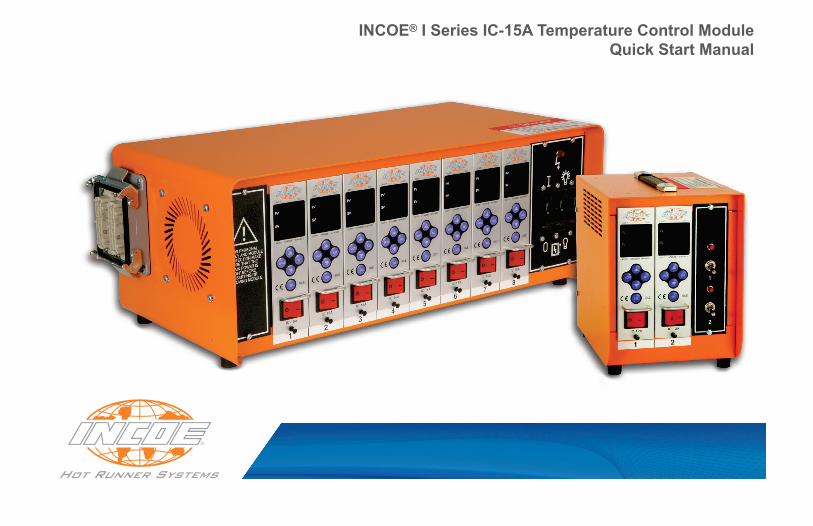
INCOE® I Series IC-15A Temperature Control ModuleQuick Start Manual

1740 E. Maple Road Troy, Mi 48083 USA T: 248-616-0220 E: [email protected] www.incoe.com© 2016 INCOE®
INCOE® Corp. Global Headquarters
INCOE® I Series IC-15A Temperature Control ModuleQuick Start Manual
Page 1 of 5 Rev. 08/16INCOE® Corp. Global Headquarters 1740 E. Maple Road Troy, Mi 48083 USA T: 248-616-0220 E: [email protected] www.incoe.com
CONTrOllEr SpECIfICATIONSInput Power: 240/230 VAC single phase
Input Power Range: 90 - 250 VAC
Max. Output Power: 3600W (15 Amps)
Frequency: 60 Hz / 50 Hz
INSTruCTIONS fOr INSTAllATIONControl Modules can be installed in industry standard PC (Portable Control) Enclosures. Before installing individual Control Modules, make certain each Module will fit into the PC Enclosure correctly and securely.Contact INCOE® for assistance if necessary.
INITIAl STArT upReferencing the input power supply diagram on the PC (Portable Control) Enclosure, connect the PC Enclosure to the appropriate plant power supply with suitable ground.
Inspect all wiring to and from the PC Enclosure.
With the power Off, install the individual Control Modules into the PC Enclosure. Note - to prevent electrical shock or damage to the I Series Controller, power to the PC Enclosure MuST be turned off when installing or removing Control Modules.
Using the circuit breaker, turn on the PC Enclosure.
Turn on individual I Series Control Modules using the power switch. Each Module will enter into an IDLE (IdL) state. Thermocouple temperature is shown on the PV display, and the Module will output 0% power.
To enter into Automatic Operation from the IDLE (IdL) state, press and hold the SEl button for one second. The Control Module will now operate with its stored parameters. To change these parameters, refer to this manual’s tables.
More InformationTo view the full Operation Manual for INCOE’s I Series IC-15A Temperature Controller, visit us at www.incoe.com.

INCOE® I Series IC-15A Temperature Control ModuleQuick Start Manual
Page 2 of 5 Rev. 08/16INCOE® Corp. Global Headquarters 1740 E. Maple Road Troy, Mi 48083 USA T: 248-616-0220 E: [email protected] www.incoe.com
MODULE INTERFACE

INCOE® I Series IC-15A Temperature Control ModuleQuick Start Manual
Page 3 of 5 Rev. 08/16INCOE® Corp. Global Headquarters 1740 E. Maple Road Troy, Mi 48083 USA T: 248-616-0220 E: [email protected] www.incoe.com
OpErATIONBasic functions
▲ / ▼ Adjust Set Value (SV)
SET Select unit digit for ▲ and ▼SEl + 1 sec. Exit IDLE (IdL) after power on
SEl + 1 sec. Change to next method of operation - Auto / Standby / Manual
MOdEChanges SV display - Set Temperature / Output % / Amps(Automatic Operation only)
MOdE + SEl + 1 sec. Initiate Boost Feature
MOdE + 3 sec. Access Settings Menu
MOdE + SET + 5 sec. Access Configuration Menu
MOdE + SET Save value - 5 seconds without a button push will also save
Error CodesError Code Display Description
1 FU-1 Fuse 1 Disconnection2 FU-2 Fuse 2 Disconnection3 tCoP Thermocouple Disconnection4 tCSt Thermocouple Short-Circuit5 tCrE Thermocouple Polarity Reverse6 AL-H High Limit Temperature Alarm7 AL-L Low Limit Temperature Alarm8 HtoP Heater Disconnection (Low Current)9 HtSt Heater Short (High Current)10 trSt Triac Short
Menu NavigationMOdE Next Menu option
▲ / ▼ Adjust numeric values
SET Select unit digit for ▲ and ▼
SET Change non-numeric values(e.g., °C or °F)
MOdE + SET Save value - 5 seconds without a button push will also save

INCOE® I Series IC-15A Temperature Control ModuleQuick Start Manual
Page 4 of 5 Rev. 08/16INCOE® Corp. Global Headquarters 1740 E. Maple Road Troy, Mi 48083 USA T: 248-616-0220 E: [email protected] www.incoe.com
MENuSSettings Menu
Setting Description Button Range
AL-H High Limit Temperature Alarm ▲ / ▼ 0 - 99
AL-L Low Limit Temperature Alarm ▲ / ▼ 0 - -99
Stbyt Standby Time
▲ / ▼ Hour: 0 - 9Min: 0 - 59
SET Convert between hour and minute
StbyP Standby Temperature % ▲ / ▼ 0 - 99%
Lock Config. Menu Lock SET On / Off
Configuration MenuSetting Description Button Range
Unit Temperature Unit Display SET 1.0 or 0.1
C--F Temperature Scale SET °F (FdSP)°C (CdSP)
-In- Thermocouple Type SET J (IC-J)K (CA-K)
SOFt - t Soft Start Time ▲ / ▼ 0 - 30 min.
HC-H High Limit Current Alarm ▲ / ▼ 0 - 20.0 A
HC-L Low Limit Current Alarm ▲ / ▼ 0 - 20.0 A
-Er- Error Code Saving Function ▲ / ▼ Search 1-20
HSCI Power Output Method SET PWM (PuN)SSR (SSr)
tUnE Auto Tuning On / Off SET On / Off
boSt - t Boost Time ▲ / ▼ 0 - 99 min.
boSt - P Boost Power % ▲ / ▼ 0 - 99.9%
SOFt - P Soft Start Power % ▲ / ▼ 10 - 50%
ΠPId NPID On / Off SET On / Off
IdLE * Idle Feature On / Off * SET On / Off

INCOE® I Series IC-15A Temperature Control ModuleQuick Start Manual
INCOE® Corp. Global Headquarters 1740 E. Maple Road Troy, Mi 48083 USA T: 248-616-0220 E: [email protected] Page 5 of 5 Rev. 08/16
www.incoe.com
DATE

INCOE® CorporationGlobal Headquarters1740 E. Maple RoadTroy, Michigan 48083 USAT: + 1 (248) 616-0220E: [email protected]
Technical Support:T: + 1 (248) 556-7790E: [email protected]
Customer Service and Sales:T: + 1 (248) 556-7770E: [email protected]