incon ts-lld installation guide manual
TRANSCRIPT

TS-LLD INSTALLATION GUIDE
Part Number: 000-1359, Rev. HCopyright © March 2012
Installation GuideTS-LLDElectronic Line Leak Detector

TS-LLD INSTALLATION GUIDE
NOTICE
INCON has strived to produce the finest possible manual for you, and to ensure that theinformation contained in it is complete and accurate. However, INCON makes no expressed orimplied warranty with regard to its contents. INCON assumes no liability for errors or omissions, orfor any damages, direct or consequential, that result from the use of this document or theequipment which it describes.
This document contains proprietary information and is protected by copyright. All rights arereserved. No part of this document may be reproduced in any form without the prior writtenconsent of INCON.
INCON reserves the right to change this document at any time without notice.
Need Help ? Contact INCON at:
INTELLIGENT CONTROLS, INC.PO Box 638SACO ME 04072
Office Hours: 8 a.m. to 5 p.m. EST Monday through Friday
Sales 24 hour Technical Service
Phone: (800) 872-3455 Phone: (800) 984-6266Fax: (207) 283-0158 Fax: (207) 282-9002E-mail: [email protected] E-mail: [email protected]
Visit our web site at: http://www.intelcon.com
INCON ® is a registered trademark of Intelligent Controls, Inc.Tank Sentinel ® is a registered trademark of INCONRed Jacket ® is a trademark of the Marley Pump Co.FE Petro ® is a registered trademark of FE Petro, Inc.The INCON TS-LLD is covered by United States Patent Number 5,918,268 (June 29, 1999)Copyright 1995, 1996, 1997, 1998, 1999 Intelligent Controls, Inc. All rights reserved.
— v —

TABLE OF CONTENTS Page TOC - 1 TOC
Table of Contents
Chapter . Section Page No.P Preface ................................................................................................. P - i
Graphic Symbol Conventions ................................................................................... P - iPage Numbering Convention – Example: ........................................................ P - iPage Layout Convention – Example: ................................................................ P - i
Components Included with Each TS-LLD System ................................................. P - iiBefore you Begin .................................................................................................... P - ii
NOTES ..................................................................................................... P - ii
1 TS-LLD Electronic Line Leak Detector – Overview .......................... 1 - 1Overview and Theory of Operation .......................................................................... 1 - 1
Leak Test Requirements and Length ................................................................. 1 - 2The LSU (Leak Sensing Unit) ............................................................................ 1 - 2Communications ................................................................................................ 1 - 2The Control Unit (CU) ........................................................................................ 1 - 3
Operator Interface ........................................................................................... 1 - 3Your Notes ............................................................................................................ 1 - 4
2.0 TS-LLD Materials & Tools Required ............................................ 2.0 - 1Do a Site Survey Before Attempting the Installation ............................................ 2.0 - 1
Submersible Turbine PumpsElectrical Supply........................................................................................... 2.0 - 1
Materials Required ............................................................................................... 2.0 - 1Tools Required ..................................................................................................... 2.0 - 2
2.1 TS-LLD SAFETY............................................................................ 2.1 - 1Important Safety Notes and Warnings ................................................................. 2.1 - 1
Safety Notes and Warnings (continued... ) ...................................................... 2.1 - 2
2.2 TS-LLD LSU Installation............................................................... 2.2 - 1LSU Installation Steps ......................................................................................... 2.2 - 1
NOTE..................................................................................................... 2.2 - 4NOTE..................................................................................................... 2.2 - 6
2.3 TS-LLD CU Installation & Wiring ................................................. 2.3 - 1Control Unit ( CU ) Installation Steps ................................................................... 2.3 - 1
NOTE..................................................................................................... 2.3 - 1TABLE 2.3 - 1 Typical Single Phase Wire Connection List ................. 2.3 - 4NOTE..................................................................................................... 2.3 - 4
TS-LLD Line Leak Detector — Mechanical Blender Interface ............................ 2.3 - 8Final Installation Steps .................................................................................... 2.3 - 14

TOC Page TOC - 2 TS-LLD INSTALLATION GUIDE
Table of Contents
Chapter . Section Page No.2.4 Optional TS-LLD – Tank Sentinel Console Interface ............... 2.4 - 1
TS-1000 Tank Gauge Interface ............................................................................ 2.4 - 1Example TS-1000 & TS-2000 ATG Reports: .................................................... 2.4 - 2TS-2000 Tank Gauge Interface ............................................................................ 2.4 - 3
NOTE..................................................................................................... 2.4 - 3Programming the TS-2000 ................................................................................ 2.4 - 4
Alarm Relays .................................................................................................. 2.4 - 4Alarm Reports ................................................................................................ 2.4 - 4
TS-1001 / TS-2001 LLDI Interface ....................................................................... 2.4 - 4Your Notes .......................................................................................................... 2.4 - 6
2.5 TS-LLD After Installation Steps & Testing .................................. 2.5 - 1After Installation Steps & Testing ...................................................................... 2.5 - 1Important — Warranty Registration ..................................................................... 2.5 - 2Important — Customer Documentation ............................................................... 2.5 - 2
3 TS-LLD System Operation & Testing ................................................ 3 - 1System Operation ................................................................................................... 3 - 1
CU Component Location & Function ................................................................... 3 - 2Control Unit Display ................................................................................................ 3 - 2
Normal Displays ( on steady / solid ) ................................................................... 3 - 2Day Counts........................................................................................................ 3 - 2
Fault Displays ( Flashing on and off ) .................................................................. 3 - 2a. Line Leak Test Failure – Flashing Leak Alarm Codes .................................. 3 - 2
When a Leak Test Fails / Line Leak is Detected: .......................................... 3 - 3b. Monthly-Compliance Warning – Flashing Day Codes .................................. 3 - 3
Indications: .................................................................................................... 3 - 3 Recommendation: ......................................................................................... 3 - 3
c. Flashing Display Error Codes ........................................................................ 3 - 3Line Leak Test light ................................................................................................. 3 - 4Line Leak Detected light ......................................................................................... 3 - 4Display Functions, Codes & Concise Instructions .................................................. 3 - 4Reset Test touch button — press to: ....................................................................... 3 - 4
NOTE........................................................................................................ 3 - 4Display Diagnostic Test Codes: ......................................................................... 3 - 4
NOTE........................................................................................................ 3 - 4

TABLE OF CONTENTS Page TOC - 3 TOC
Table of Contents
Chapter . Section Page No.3 TS-LLD System Operation & Testing (continued... )
Starting a 0.1 gph Annual Precision Leak Test ................................................ 3 - 4 Requirements: ............................................................................................... 3 - 4Definition: quiet-time ..................................................................................... 3 - 4 How to Start a Manual Test ........................................................................... 3 - 5
Normal Operation – Sequence of Events / Steps ............................................... 3 - 51.) Product Dispense – Begin
( dispense: nozzle out / lever up / switch on ) ............................................. 3 - 52.) Product Dispense – End
( dispense: nozzle in / lever down / switch off ) ........................................... 3 - 53.) The 3.0 gph Gross Hourly Test .................................................................... 3 - 54.) The 0.2 gph Monthly-Compliance Test ........................................................ 3 - 5
NOTE........................................................................................................ 3 - 5 A 0.2 gph Test Automatically Starts When: ................................................... 3 - 6
Out of Compliance ............................................................................................ 3 - 6
Frequently Asked Questions:Why do Days Count Up ? ............................................................................... 3 - 7Why do Error Codes 29, 30, 31, or 32 Appear ? ........................................... 3 - 7How do I Display the Last Alarm or Error Code ? .......................................... 3 - 7How do I Reset Flashing Error Codes ? ...How do I Allow Dispensing ?...How do I Clear Flashing Codes ? ............................................................... 3 - 7Why can’t I Reset and Dispense ? ................................................................. 3 - 7How Do I Verify a Leak ? ................................................................................ 3 - 7How do I Start a Manual Test ? ...................................................................... 3 - 8How Often Should the Manual Test be Run ? ............................................... 3 - 8
What Should I Do:When a 3 gph Leak Test Fails / Gross Leak is Detected ? ............................ 3 - 8When a 0.2 gph Leak Test Fails / Leak is Detected ? ................................... 3 - 8When a 0.1 gph Annual Precision Leak Test Fails / Leak is Detected ? ....... 3 - 8
4 TS-LLD Line Leak Detection .............................................................. 4 - 1When a Line Leak is Detected................................................................................ 4 - 1
NOTE........................................................................................................ 4 - 1Steps to take When a Line Leak is Detected: ..................................................... 4 - 1
NOTE........................................................................................................ 4 - 2How Often Should a Manual ).1 gph Test be Run ? ................................................ 4 - 2
Need help ? ....................................................................................................... 4 - 2

TOC Page TOC - 4 TS-LLD INSTALLATION GUIDE
Table of Contents
Chapter . Section Page No.5 TS-LLD Maintenance & Service......................................................... 5 - 1
NOTE........................................................................................................ 5 - 1Cleaning the Control Unit ........................................................................................ 5 - 1Control Unit Replacement Parts ............................................................................. 5 - 1Pump Relay Control Box Replacement Parts ......................................................... 5 - 1Leak Sensing Unit (LSU) Adapters & Replacement Parts ..................................... 5 - 2
LSU Removal for Service / Inspection and Cleaning ........................................ 5 - 2After Maintenance or Service DO – .................................................................. 5 - 2
6.0 Service & Factory Support .......................................................... 6.0 - 1Where to Find Help .............................................................................................. 6.0 - 1Service ................................................................................................................. 6.0 - 1Need help ? Factory Support ............................................................................. 6.0 - 2
Phone and Pax members: ................................................................................ 6.0 - 2Sales & Tech. Service numbers,
Technical Service & After Hours – Pager – ................................................ 6.0 - 2INCON Office Hours....................................................................................... 6.0 - 2Before calling INCON ..................................................................................... 6.0 - 2
Return Shipments ................................................................................................ 6.0 - 2Warranty Registration Form (copy, & Fax Reg. Form back to INCON) ....... 6.0 - 3
Your Notes ......................................................................................................... 6.0 - 4
6.1 Test Fail Alarms, Warnings & Error Codes ................................ 6.1 - 1Display Codes ..................................................................................................... 6.1 - 1
Normal Display Codes (on steady – not flashing) ......................................... 6.1 - 1Flashing Alarms, Warnings, and Errors Display Codes ............................... 6.1 - 1Diagnostic Display Codes (on steady – not flashing) ................................... 6.1 - 1
Your Notes ......................................................................................................... 6.1 - 2
6.2 TS-LLD Troubleshooting Guide .................................................. 6.2 - 1Display Codes ...................................................................................................... 6.2 - 1
Problem Description/Symptom Probable Cause (Action to take) ....... 6.2 - 1NOTE..................................................................................................... 6.2 - 2
Your Notes ......................................................................................................... 6.2 - 4
6.3 TS-LLD Warranty & Terms ........................................................... 6.3 - 1Warranty .............................................................................................................. 6.3 - 1Warranty Disclaimer and Limitation of Liability ................................................... 6.3 - 1
For Further Information, Contact INCON ........................................................... 6.3 - 2Your Notes ......................................................................................................... 6.3 - 2

TABLE OF CONTENTS Page TOC - 5 TOC
Table of Contents
Chapter . Section Page No.Appendix A TS-LLD Technical Specifications ......................................... A - 1
Operating Specifications ......................................................................................... A - 1Electrical Specifications .......................................................................................... A - 1Allowable Pipe Type and Length ............................................................................. A - 1Environmental Specifications .................................................................................. A - 2Mechanical Specifications ...................................................................................... A - 2Safety Approvals and Listings ................................................................................ A - 2
User Feedback Form .......................................................................................... U - 1
Table of Figures & Diagrams
Chapter . Section Page No.Chapter 1
Figure 1.1 LSU Outline ...................................................................... 1 - 1Figure 1.2 CU Outline Dimensions ...................................................... 1 - 1
Chapter 2 . Section 2Figure 2.2-1 MI Cable Adapter Installation (before and after) ............ 2.2 - 1Figure 2.2-2 Plug Location – RedJacket STP Housing ...................... 2.2 - 2Figure 2.2-3 Plug Location – FE Petro STP Housing ......................... 2.2 - 3Figure 2.2-4 TS-LLD Leak Sensing Unit – Thread Doping ................ 2.2 - 3Figure 2.2-5 Line Leak Detector Installation – RedJacket Pump ....... 2.2 - 4Figure 2.2-6 Line Leak Detector Installation – FE Petro Pump .......... 2.2 - 5Figure 2.2-7 Line Leak Detector Wiring – RedJacket Pump .............. 2.2 - 6Figure 2.2-8 Line Leak Detector Wiring – FE Petro Pump Housing ... 2.2 - 7Figure 2.2-9 MI Cable Adapter Installation – RedJacket Pump ......... 2.2 - 8Figure 2.2-10 MI Cable Adapter Installation – FE Petro Pump ............ 2.2 - 9Figure 2.2-11 Tightening MI Cable Adapter Fitting – RedJacket ....... 2.2 - 10Figure 2.2-12 Tightening MI Cable Adapter Fitting – FE Petro .......... 2.2 - 11Figure 2.2-13 Typical Installation TS-LLD Line Leak Detector ........... 2.2 - 12Figure 2.2-14 INCON TS-LLD Installation @ Ext. Leak Det. Port ...... 2.2 - 13Figure 2.2-15 INCON TS-LLD Installation at BigFlo
Diaphragm Valve ..................................... 2.2 -14 & 2.2 - 15Figure 2.2-16 INCON TS-LLD Installation at FE Petro
STP or IST pumps (Single or Three Phase) ............. 2.2 - 16

TOC Page TOC - 6 TS-LLD INSTALLATION GUIDE
Table of Figures & Diagrams
Chapter . Section Page No.Chapter 2 . Section 3
Figure 2.3-1 CU Internal & Bottom Views, and Relay Box Top View .. 2.3 - 1Figure 2.3-2 CU Component Location - Internal View........................ 2.3 - 2Figure 2.3-3 TS-LLD CU Typical Mounting and Conduit Routing ....... 2.3 - 3
TABLE 2.3 -1 Typical Single Phase Wire Connection List .............. 2.3 - 4Figure 2.3-4 Typical Single Phase 240 VAC
Pump Relay Box & Control Unit Wiring Diagram ........ 2.3 - 5Figure 2.3-5 Typical Single Phase 240 VAC
Pump & Control Unit Interface Schematic .................. 2.3 - 6Figure 2.3-6 Single Phase 240 VAC Multiple Pump & Manifolded
Line w/ Single LSU & CU Interface Schematic .......... 2.3 - 7Figure 2.3-7 Mechanical Blender Dispensers to
TS-LLD Control Unit Interface Schematic .................. 2.3 - 8Figure 2.3-8 Three Phase 240 VAC Pump & Control Unit
Interface Schematic .................................................... 2.3 - 9Figure 2.3-9 Three Phase 240 VAC Supply – Starter – Motor
Control Box – and BigFlo Pump (3 wire)Interface Schematic to TS-LLD ................................ 2.3 - 10
Figure 2.3-10 Three Phase 240 VAC Supply – Starter – MotorControl Box – and BigFlo Pump (5 wire)Interface Schematic to TS-LLD ................................ 2.3 - 11
Figure 2.3-11 Three Phase 240 VAC Supply – Starter & MotorControl Box – Standard (FE Petro STP)Interface Schematic to TS-LLD ................................ 2.3 - 12
Figure 2.3-12 Three Phase 240 VAC Supply – FE PetroVariable Frequency Controller (VFC),Motor Control Box – and IST PumpInterface Schematic to TS-LLD................................. 2.3 - 13
Figure 2.3-13 Control Unit Final Assembly ......................................... 2.3 - 14
Chapter 2 . Section 4Figure 2.4-1 TS-1000 & TS-TGI Layout .............................................. 2.4 - 1Figure 2.4-2 TS-1000 & TS-TGI – TS-LLD Wiring Diagram ............... 2.4 - 2Figure 2.4-3 TS-2000 – TS-LLD Line Leak Detector Interface .......... 2.4 - 3Figure 2.4-4 TS-1001 / 2001 Typical Hardware Layout ...................... 2.4 - 4Figure 2.4-5 TS-1001 / 2001 LLDI Wiring Diagram ........................... 2.4 - 5
Chapter 3Figure 3-1: Control Unit Cover – Component Location ....................... 3 - 2
Chapter 5LSU Bottom & Side Views ........................................................................ 5 - 2
— v —

PREFACE Page P - i P
P PREFACE
Graphic Symbol Conventions
Important information, tips, and hints are highlighted by the NOTE graphic.
CAUTION or WARNING messages are highlighted by the WARNINGgraphic and contain instructions that must be followed to avoid faulty equipmentoperation, or an explosion or shock hazards. If ignored, severe injury or death mayresult !
DANGER messages are highlighted by the DANGER graphic and containinstructions that must be followed to avoid an explosion or electrical shockhazard. If ignored, severe injury or death will result !
— v — End of Chapter symbol
Page Numbering Convention – Example:Page 4 – 1 = Chapter 4 page 1 and Page 6.1 – 2 = Chapter 6 . Section 1 – Page 2
Page Layout Convention – Example:
Contents:Graphic Symbol Conventions (used in this manual)Page Numbering and Layout ConventionsComponents Included with Each TS-LLD SystemBefore You Begin
NOTE+
Page Number
Chapter Name(ODD NUMBEREDPAGES)
Chapter Number
Manual Name(EVEN NUMBERED
PAGES)
Page Number
Chapter Number
Chapter Number &Name (TOP LEFTFIRST PAGE)Chapter Contents

P Page P - ii TS-LLD INSTALLATION GUIDE
Components Included with Each TS-LLD System(TS-LLD Packing List)
(1) CU – Control Unit enclosure assembly (with stick-on CU Serial No. label)(1) CU – Control Unit faceplate cover assembly
* – (4) CU cover hold-down screws (4-40 x 1/4 inch)(1) Bundle of different colored wire (Wire Bundle)
* – (1) Spare 1/2 Micro Amp Fuse (F1)
* – (1) Line Filter Capacitor, 1 µ Farad (for pump relay / motor control box)(1) Sheet of (9) stick-on – DANGER labels(1) LSU – Leak Sensing Unit (with stick-on LSU Serial No. label)(1) Cable adapter (2 inch NPT) – (for Red Jacket Pumps)
* – (1) Plug (1/4 inch NPT)
* – (2) Wire Nuts (red) – (for connections at pump)(1) Warranty Registration Card (write / stick-on CU & LSU Serial No. labels)(1) TS-LLD Installation Guide Manual(1) Read Me First – Installation Guide (Supplement Sheet)(1) TS-LLD Quick Reference Guide (for the station owner / customer)
* – Denotes parts in the supplied Hardware Kit (within plastic accessory bag)
Before you Begin
Refer to all applicable Local and State codes before beginning this installation. If aconflict exists between the information presented in this manual, and the localcodes, then follow the local codes.
Maintenance, Service, and Installation of the TS-LLD system is to be performed byFactory Trained and Certified personnel only.
Heed all CAUTIONS and WARNINGS ! See Chapter 2.1 about Safety, beforeattempting any installation, maintenance, or service work.
This manual is your reference guide for the INCON TS-LLD line leak detector. Itincludes typical installation details, which may vary depending on the actualequipment at the site. Reference the Submerged Turbine Pump (STP) orsubmersible pump, and pump relay (Motor Control) box — manufacturers’documentation — for the installation details and requirements of this equipment.
— v —
NOTES+

Overview Page 1 - 1 1
1 TS-LLD ElectronicLine Leak Detector system –Overview
Overview and Theory of OperationThe INCON TS-LLD is an electronic line leak detectorsystem. It has two components: a Control Unit (or CU)and a Leak Sensing Unit (or LSU). The CU is mounted inthe station near the pump control relay box, and the LSU isinstalled in the line leak detector port at the submersiblepump housing. One system per pump is required to detectleaks from a pressurized fuel line.
The TS-LLD detects leaks in the pipeline leading from thesubmersible pump to the dispenser. To comply withcurrent EPA regulations, three types tests are provided.These are: a 0.1 gph annual test, a 0.2 gph monthly test,and a 3.0 gph hourly test, which run at full line pressure.
8 I N C HL E A D S
M I C A B L EA D A P T E R
- J U N C T IO NB O X S I D E
2 3 .5 I N C H E SA P P R O X .O V E R A L LL E N G T H
A S S E M B L E D
2 I N C H N P T- L IN E L E A K
P O R T S I D E
M I C A B L E
Figure 1.1 LSU Outline Figure 1.2 CU Outline Dimensions
3 . 3 5
TS-LLD
CU
Serial N
umber
x x x x x x x x
F R O N T V I E W R I G H T S I D E V I E W
xxxxxxxx
Line #:P roduct:
4 . 3 5
2 . 2 5
0 . 6 0 K n o c k o u t f o r 1 / 2 in c h f it t in g
- T y p ic a l -
No te : A ll Dimens ions are in inc hes , and are approx ima te
TO P & B O TTO M V I E W - C O N TR O L U N I T (C U )
Contents:• Overview and theory of
Operation• Leak Test Requirements
and Length
• The LSU (Leak Sensing Unit)• Communications• The CU (Control Unit)• Operator Interface

1 Page 1 - 2 TS-LLD INSTALLATION GUIDE
Overview and Theory of Operation (Continued... )The 0.1 gph annual test is started manually from the control unit (also known as amanual test). On the other hand, the gross 3.0 gph hourly test and theintermediate precision 0.2 gph monthly-compliance test both start and runautomatically. Quiet-times, where no dispensing occurs, are required to startand finish any line leak test.
Leak Test Requirements and Length
The 3.0 gph hourly test starts after every dispense and takes about 3 minutesof quiet-time to finish.
The 0.2 gph monthly-compliance test automatically starts after a 3.0 gph testpasses unless a previous 0.2 gph test has already passed within the last 24hours. The monthly compliance test either runs, passes, and resets the day-countto 00, or, advances a day if no test has passed after 24 hours. Depending onconditions of the line and product, the 0.2 gph monthly-compliance test needs13 minutes to 4 hours of quiet-time to finish.
The manual 0.1 gph annual test needs 4 hours of quiet-time before it’sstarted, and takes about 13 minutes of quiet-time to finish after it starts.
The LSU (Leak Sensing Unit)
The LSU (Leak Sensing Unit) has an O-Ring sealed valve at its base, which forcesall of the fuel flowing from the submersible pump through the LSU. Amicroprocessor based printed circuit board is contained in the LSU. It uses aproprietary technique to measure the actual product flow rate through a sensortube within the LSU, which can indicate a leak.
In most cases, the only required field wiring connections are two wires that areconnected in parallel to the existing Submersible Turbine Pump (STP) power-feed-lines. A special copper sheathed, Mineral Insulated Cable (MI Cable) connects theLSU to the electrical junction box at the pump discharge head.
Communications
The LSU not only receives power from the existing pump power-lines, but ittransmits data (communicates) over these lines. One of the power lines is routedthrough a communications pickup coil inside the Control Unit (CU).

Overview Page 1 - 3 1
The CU (Control Unit)
The CU monitors data that it receives from the pickup coil. The control unitautomatically turns on the pump when no one is dispensing product and calculatesaccurate liquid flow rates to determine if a line leak exists or not.
The dispense signal is also monitored to identify when a customer is about todispense product. The CU is tied directly to the existing Pump Relay (MotorControl) Box that is inside the station. The control unit activates the pump relay,which turns the pump on and permits product dispensing when no line leak orerrors exist. When a leak or error is detected, the pump relay is deactivated, whichkeeps the pump turned off and prevents product dispensing.
Operator Interface
Two lights, a 2 digit display, and a reset-test touch button are provided for operatorinterface. One light turns on when leak tests run, and the other flashes when a lineleak is detected. The two digit display shows operational status codes / day counts(since the last monthly 0/2 gph line leak test passed), or flashes line leak alarms,warnings, and error codes when and if they occur.
Brief operating instructions, and a list of codes and display functions are printed onthe control unit faceplate. See Chapter 3 for complete details.

1 Page 1 - 4 TS-LLD INSTALLATION GUIDE
— Your Notes —
— v —

Materials and Tools Required Page 2.0 - 1 2.0
2.0 TS-LLD Materials & ToolsRequired
Do a Site Survey Before Attempting the Installation
Submersible Turbine Pumps:What is the Motor Control / Pump Relay Box or Starter Type ? andWhat is the Model Number, HP, Manufacturer, and age of all Turbine Pumps ?
Electrical Supply:What is the Voltage and Phase (240 VAC – Single or Three Phase ? ) of allTurbine Pumps ?
Materials Requiredr Petroleum absorbent / absorbing ragsr Pipe Dope — Non-hardening (Soft-Set), UL Classified, gas/oil resistant —
to seal the Leak Sensing Unit, and the 1/4 inch Tank Test Port plug at the pumpr MI Cable Adapter — for installation on the TS-LLD Leak Sensing Unit (LSU). The
TS-RJ 2" NPT Cable Adapter for Red Jacket® submersible pumps is (suppliedwith the TS-LLD), the adapter for FE Petro® STPs must be ordered separately...Order INCON part number:TS-FE 3" straight Cable Adapter for FE Petro® STPs *
r Stick-on DANGER labels (INCON P/N 240-1175 – supplied with the TS-LLD)
r (1) 1/4 inch NPT pipe plug for the tank test port at the pump head (supplied withthe TS-LLD)
r Red wire nuts for LSU wiring at the pump head (supplied with the TS-LLD)r (1) 1µ Farad Line Filter capacitor for the pump relay box (INCON P/N 020-0028
– supplied with the TS-LLD)r Wire: 14 AWG, 3 feet (supplied with the TS-LLD)r (6) spade lugs for #8 studs to connect the 14 AWG wire at the pump relay box
Contents:• Do a Site Survey Before Attempting the Installation• Materials Required• Tools Required

2.0 Page 2.0 - 2 TS-LLD INSTALLATION GUIDE
Materials Required (continued... )r (1) ring lug for the 14 AWG earth ground connection at the pump relay boxr (1) short 1/2 inch nipple — 2-1/2 to 3 inches long, or 1/2 inch 90 degree, and
hardware fittings to mount the CU to the relay box. (Or you may wall-mount thecontrol unit with appropriate fasteners, and use 1/2 inch EMT and fittings.)
r * Steel stem Replacement Check Valve Kit (RedJacket P/N 144-184-5) toreplace older all plastic check valves – for older RedJacket pumps only
r * Approved Pump Relay (Motor Control) Box – to comply with codes, retrofitsystem to add a motor control box inside of the station* = Occasionally Required
r this Installation Manual – INCON P/N 000-1359 most current revisionr (1) Completed Warranty Registration Card – (supplied with each TS-LLD)r TS-LLD Quick Reference guide – INCON P/N 000-1447 (supplied with each
TS-LLD). Leave all TS-LLD Quick Reference guide(s) on-site for use by thestation owner, shift managers / personnel !
r Also, for use by the station owner, shift managers / personnel, provide thename(s), phone number(s) of the local inspection agency and other applicableinformation, instructions and regulations should a line leak be detected.
r Regulations and documentation: Applicable Local and State Codes, theManufacturers’ manuals and wiring diagrams of the — Dispenser, SubmersiblePump, and Relay Box (including other equipment not listed here and the sites’electrical power distribution).
Tools Requiredr Digital multimeter and test leads (high quality professional instrument)r One each: wire strippers, cutters, and crimp splice toolr Various sizes of flat and phillips bladed screwdriversr One 12 inch long adjustable wrenchr One 2 inch open end hex wrenchr Two 7/8 inch open end hex wrenchesr One socket set, extension, and square socket for a 1/4 inch NPT square headed
hole plug
— v —

SAFETY Page 2.1 - 1 2.1
2.1 TS-LLD SAFETY
Important Safety Notes and WarningsDANGER Electrical Shock Hazard. Before installing,servicing, or working on this equipment, make sure you turn off allsubmersible pump power (240 VAC) and pump relay coil /dispenser power at the electrical panel. Tag, secure / lockoutthese circuit breakers in the off position to prevent accidental orunauthorized circuit breaker closure. Failure to turn off powerwill result in severe injury or death !
DANGER Verify that no voltage exists before working-on, or wiring-to a circuit – a lethal electrical-shock-hazard couldexist, which would kill you. Note: circuit breaker contact(s) can failin the on position, even when the circuit breaker lever is turned off.
DANGER The TS-LLD automatically starts the submersiblepump to run leak-tests at full line pressure between periods ofproduct dispensing (while the dispense switch is off). BEFOREperforming any installation or service (such as replacing fuel-filters) – turn off / lockout all electrical power sources to thesubmersible pump(s), and relieve fuel-line pressure. Failure toturn off power, and relieve fuel-line pressure before work is started,may cause a pressurized fuel spill. A pressurized fuel spill wouldcreate a fire or explosion hazard that could result in injury or death.
INCON Danger stickers (see above left) are supplied with theTS-LLD line leak detector. Apply these stickers on the pump relaybox cover, in locations near dispenser fuel-line filters, plugs,emergency safety-shut-off valves, on the TS-LLD Leak SensingUnit (at the submersible pump housing), and other serviceablecomponents of a fuel line (where a spill would occur if the linebecame pressurized). The selected surfaces must be clean, dry,and in plain sight so that the warning can be read, and followed.
NOTE
+
Contents:• Important Safety Notes and Warnings...
Read and follow these DANGER, WARNING, and CAUTIONmessages before starting any installation or service.

2.1 Page 2.1 - 2 TS-LLD INSTALLATION GUIDE
Safety Notes and Warnings (continued... )
DANGER Explosion Hazard — Flammable Vapor Area.After any installation or service of the submersible pump or itshousing, inspect the MI Cable at the LSU (Leak Sensing Unit) fordamage, twists, kinks, or breaks... 240 VAC power flows throughthis cable to the LSU. DO NOT apply power if the MI Cable isdamaged, twisted, kinked, or broken. Electrical sparks or fire inthis area could cause an explosion, injury or death.
WARNING The fuel line from the submersible pump to thedispenser, may be under pressure. Turn off all pump power andrelieve pipeline pressure (reference and follow the pumpmanufacturer’s directions about how to do this). If the line leakdetector/plug (or any other part of the submersible pump and fuelline) is removed without first relieving pressure, then a productleak will occur. This could cause an environmental, fire, orexplosion hazard, and may result in injury or death.
WARNING Be careful not to cause sparks when working onfuel dispensing equipment (volatile fuel may be within the pump’sleak detector port). Allow no source of combustion near the workarea. Failure to follow these directions may cause an explosionhazard, which could result in property damage and death.
CAUTION Refer to all applicable Federal, State and localcodes, the National Electric Code (NEC), and the Automotive andMarine Service Station Code (NFPA 30A) before installation ormaintenance. This installation is designed for submersible pumpswhich have a pump relay box in the station. If a pump relay boxdoes not exist, then the system must be retrofitted to add apump relay (motor control) box in the facility to comply withCodes.
CAUTION Although the LSU is water resistant, INCON doesnot recommend operating the LSU while submerged for longperiods of time (drain sump and manhole immediately).
— v —

LSU Installation Page 2.2 - 1 2.2
2.2 TS-LLD LSU Installation
LSU Installation StepsFollow the steps (below) in the order that they appear:
1) Install the appropriate size MI Cable Adapter on the LSU. Use an adjustablewrench and a 7/8 inch wrench to tighten the MI cable adapter onto the TS-LLD asshown in Figure 2.2-1. NOTE: The cable adapter that you install must match thesize of the junction box plug at the submersible pump housing (two different cableadapters are shown in Figure 2.2-1). The 3 inch straight TS-FE cable adaptermust be ordered separately because the pump type and manufacturer varies.
Figure 2.2-1 MI Cable Adapter Installation (before and after)
TS-LLDLINE LEAK DETECTORLEAK SENSING UNIT(LSU)
TS-FE3 INCHM I CABLEADAPTER TS-RJ
2 INCH NPTM I CABLEADAPTERFor FE Petro
Pumps For Red JacketPumps
Contents:• LSU Installation Steps
(Typical in Pump Housing)• Overall Site Installation Diagrams (typical Site,
in Angle Check Valve, RedJacket “BigFlo,” & FEPETRO STP / IST pumps)

2.2 Page 2.2 - 2 TS-LLD INSTALLATION GUIDE
DANGER Fire, Explosion, & Electrical Shock Hazard. Before installing,servicing, or working on this equipment, make sure all submersible pump powerand pump relay coil / dispenser power is turned off & locked out at the electricalpanel. Prevent automatic or unauthorized pump start-ups, spills from pressurizedlines, and electrical shocks. See Chapter 2.1 follow all Safety advise.
2) Relieve pipe line pressure. Reference the detailed instructions found in thesubmersible pump manufacturers’ documentation about relieving pressure in thepipe line.
WARNING The pipe line is under pressure – relieve line pressure. If theline leak detector / plug is removed before the pipe line pressure is relieved, then aproduct leak will occur ! A explosion, fire, or environmental hazard may be created.
3) Remove the 2 or 3 inch junction box plug and the 2 inch line leak plug, ormechanical line leak detector (if present), from the pump housing per Figure 2.2-2or 2.2-3. Use petroleum absorbent / absorbing rags to collect and contain spills ifthey occur (be sure to properly dispose of these afterwards). If a mechanical lineleak detector was removed, then apply pipe dope on the threads of thesupplied 1/4 NPT hole plug, and install this plug into the tank test port.
Figure 2.2-2 Plug Location – RedJacket® Submersible Pump Housing
PUMP HOUSING
STATIONC OND UIT
1/4" PLUG
PIPELINE
MEC HA NIC ALLINE LEAKD ETEC TOR
2" PLUG
2" PLUG

LSU Installation Page 2.2 - 3 2.2
4) Apply Pipe dope to the line leak detector threads per Figure 2.2-4.
Figure 2.2-3 Plug Location – FE Petro Submersible Pump Housing
Figure 2.2-4 TS-LLD Leak Sensing Unit – Thread Doping
PipeDope
TS-LLDLINE LEAK DETECTORLEAK SENSING UNIT(LSU) Pipe dope
only thesethreads
1/4" PLUG
PUMP HOUSING
STATIONC OND UITPOR T
3" PLUG
2" PLUG
PIPELINE

2.2 Page 2.2 - 4 TS-LLD INSTALLATION GUIDE
5) Insert the Leak Sensing Unit into the line leak port at the pump housing. SeeFigure 2.2-5, or 2.2-6, and tighten the detector with a 2 inch hex – open endwrench (no larger than 12" long to prevent overtightening and possible pumphousing damage or leaks). DO NOT overtighten the LSU in the pump head !
The MI Cable should be straight, vertical and able to rotatefreely with the LSU during the insertion or removal process.
Figure 2.2-5 Line Leak Detector Installation – RedJacket® Pump Housing
NOTE
+
PIPE LIN E
M I C A B L E
S TA T IO NC O N D U IT
P U M PH O U S IN G
L IN E L E A KD E T E C TO R
M I C A B L EA D A P TE R

LSU Installation Page 2.2 - 5 2.2
Figure 2.2-6 Line Leak Detector Installation – FE Petro Pump Housing
PUMPHOUSING
STATIONCONDUITPORT
M I CABLEADAPTER
LINE LEAKDETECTOR
MI CABLE

2.2 Page 2.2 - 6 TS-LLD INSTALLATION GUIDE
6) Carefully bend the thin-wall MI cable by hand and align the 2 or 3 inch cableadapter fitting with the junction box plug opening. Support the MI cable with bothhands when bending to fit. DO NOT force or bend the MI cable against thecompression fittings. Be sure you leave enough room to work (as shown in Figure2.2-7, or 2.2-8).
Avoid breaking the MI cable — DO NOT bend the MI cable tooclose to the fittings. An LSU that has a damaged MI Cable isunusable and must be replaced before power is applied.
7) Carefully remove each wirenut, one at a time and check each for the absence ofpower (see Figure 2.2-7, or 2.2-8).
Figure 2.2-7 Line Leak Detector Wiring – RedJacket® Pump Housing
NOTE
+
PUMPHOUSING
STATIONCONDUIT
M I CABLE
LINE LEAKDETECTOR
PIPELINE

LSU Installation Page 2.2 - 7 2.2
Figure 2.2-8 Line Leak Detector Wiring – FE Petro Pump Housing
DANGER Make sure you check these wires for the absence of powerbefore proceeding. All pump power (240 VAC) and pump relay / dispenser powermust be off before this installation is started, otherwise a lethal hazard will becreated which could kill you or others. Note: A circuit breaker contact(s) canstick closed even when the circuit breaker is in the off position.
8) Leak Sensing Unit Wiring – Reference Figure 2.2-7, or 2.2-8.a) Use one of the supplied red wire nuts, and twist one wire lead from pump
together with one of the black wire leads from the LSU.b) Again use a red wire nut, and twist the remaining lead from pump together
with the remaining black wire lead from the LSU.c) For Canadian TS-LLD leak sensing units only: connect the green (ground)
wire from the pump to the green LSU wire.
PUMPHOUSING
STATIONCONDUIT
PORT
M I CABLEADAPTER
M I CABLE
PIPELINE
LINE LEAKDETECTOR

2.2 Page 2.2 - 8 TS-LLD INSTALLATION GUIDE
9) Stuff the wires back into the pump housing and carefully finish bending the MIcable so that the cable adapter engages the threaded opening of the junction box.Make sure to push the wires down enough to avoid pinching, or cutting throughthe wire insulation from the cable adapter when it is tightened down. ReferenceFigure 2.2-9, or 2.2-10.
10) Tighten the MI cable adapter (new junction box cover) after making sure thatcompression fitting is loose and is able to rotate freely — to prevent bendingand twisting damage to the MI Cable. Apply electrically conductive pipe dope tothe cover or the junction box. Use a 12 inch adjustable wrench. Reference Figure2.2-9, or 2.2-10.
Figure 2.2-9 MI Cable Adapter Installation – RedJacket® Pump Housing
M I CABLE
STATIO NCONDUIT P I P E L I N E
PUMPHO USING
LINE LEAKDETECTOR

LSU Installation Page 2.2 - 9 2.2
Figure 2.2-10 MI Cable Adapter Installation – FE Petro Pump Housing
STATIONCONDUIT
PORT
PUMPHOUSING
M I CABLEADAPTER
M I CABLE
PIPELINE
DETECTORLINE LEAK

2.2 Page 2.2 - 10 TS-LLD INSTALLATION GUIDE
11) Tighten the MI cable compression fitting with a 7/8 inch wrench. Be carefulnot to overtighten the compression fitting – avoid MI cable twisting / bendingdamage and failures – torque to 25 lbs/ft. Reference Figure 2.2-11, or 2.2-12.
12) Recommended for Red Jacket installations: inspect and replace the check valveunder the functional element – IF – it doesn’t have a stainless steel stem. UseRed Jacket replacement part number: 144-184-5.
13) Finally, inspect the MI Cable at the LSU (Leak Sensing Unit) for damage, twists,kinks, or breaks — a LSU that has a damaged MI Cable is unusable and must bereplaced before power is applied. Install a new LSU if the MI Cable is damaged.
Figure 2.2-11 Tightening MI Cable Adapter Compression Fitting – RedJacket® Pump
M I C A B L E
DETAIL A
M I Cable
Lower Junction Box / Cable Adapter Fitting
UpperCompression Fitting
StainlessSteelstem
Check V alveDetail
Plastic
P UM PHO US ING
S T A T IO NC O ND UIT P IP E L INE

LSU Installation Page 2.2 - 11 2.2
Figure 2.2-12 Tightening MI Cable Adapter Compression Fitting – FE Petro Pump
PUMPHOUSING
STATIONCONDUIT
PORT
M I CABLEADAPTER
M I CABLE
DETAIL A
M I Cable
Lower Junction Box / Cable Adapter Fitting
UpperCompression Fitting
PIPELINE
LINE LEAKDETECTOR
DANGER Explosion Hazard — Flammable Vapor Area.After any installation or service of the submersible pump or itshousing, inspect the MI Cable at the LSU (Leak Sensing Unit) fordamage, twists, kinks, or breaks... 240 VAC power flows throughthis cable to the LSU. DO NOT apply power if the MI Cable isdamaged, twisted, kinked, or broken. Electrical sparks or fire inthis area could cause an explosion, injury or death.

2.2Page
2.2-12
TS-LLD INSTALLATION GUIDE
Figure 2.2-13 Typical Installation INCON TS-LLD Line Leak Detector
INCON TS-LLD Line Leak DetectorTypical Installation in Leak Detector Port
TS-LLD LSU # 1(Leak Sensing Unit # 1)
at submersib le pump hous ing
Tank - Pump # 1
Electr ical Power Panel
P u m pRelay
Boxes
NOTE: A TS-TGI Tank Gauge Interfacemodule is required to connect the TS-LLD Line Leak Detector system to an INCON TS-1000 Tank Sentinel console.
See the TS-TGI Instal l Manual.
Exist ingConduit
(Pump 2)
Exist ingConduit (Pump 1)
SubmergedTurb ineP u m p
12
TS-LLD CUs(Control Units):# 2 and # 1
TS-LLD LSU # 2(Leak Sensing Unit # 2)
at submersib le pump hous ing
Tank - Pump # 2
EpoxyFil ledEYSSeal
Fitt ing
Dispenser# A
Explos ion-proofJunct ionBox
Dispenser# X
NOTE:A TS-TGI Tank Gauge Interfacemodule is required to connect theTS-LLD Line Leak Detector systemto an INCON TS-1000 Tank Senti-nel console. See the TS-TGI InstallManual.
For TS-1001/2001 Tank Sentinelconsoles, use the LLD / I interface...see the OPTIONAL TS-LLD TANKSENTINEL ATG CONSOLEINTERFACE chapter in this manual.
Reference Schematic Figure 2.3 - 8

LSUInstallation
Page2.2
-13
2.2
Figure 2.2-14 INCON TS-LLD Installation at External Leak Detector Port
Tank - Pump # 1("Standard" Single Phase
Installation)
Exist ingConduit (Pump 1)
TS-LLD CUs(Control Units):# 2 and # 1
INCON TS-LLD Line Leak Detector
External Leak Detector Port Installation
Exist ingConduit
(Pump 2)
SubmergedTurbinePump (STP)
1
PumpRelay
Boxes2
Electrical Power Panel
EpoxyFil ledEYSSeal
Fitting
Tank - Pump # 2Installation within an
External Leak Detector Port ( not pump housing)
Explosion-proofJunct ionBoxes
TS-LLD LSU (#2)(Leak Sensing Unit)
at External Leak Detector Port
TS-LLD LSU (#1)(Leak Sensing Unit)
at STP housingStandard
Single Phase Instal lat ion
Dispenser# A
Dispenser# X
NOTE:A TS-TGI Tank Gauge Interfacemodule is required to connect theTS-LLD Line Leak Detector systemto an INCON TS-1000 Tank Senti-nel console. See the TS-TGI InstallManual.
For TS-1001/2001 Tank Sentinelconsoles, use the LLD / I interface...see the OPTIONAL TS-LLD TANKSENTINEL ATG CONSOLEINTERFACE chapter in this manual.
Reference Schematic Figure 2.3 - 8

2.2Page
2.2-14
TS-LLD INSTALLATION GUIDE
INCON TS-LLD Line Leak DetectorBigFlo & Diaphragm Valve Installation
Tank - Pump # 1("Standard" Single Phase
Installation)
TS-LLD LSU (#1)(Leak Sensing Unit)
at pump housingStandard Single
Phase Instal lat ion
NOTE:1)
2)
An addit ional Single Phase 230 VAC Relay Control Box (panel), two addit ional wires, and possibly an addit ional conduit run tothe LSU, are required for 3 Phase Applications.
The INCON TS-LLD LSU MUST be instal led so the fasteners are al igned in a 12 & 6 o'clock(vertical) posit ion as shown in Detail A - A. Tighten the LSU to meet this requirement.
Detail A - AOverhead Top View (correct alignment)
PartialEnlargedSide View
SubmergedTurb ine
Pump (STP)
ExistingCondui t
(Pump 2)
Electrical Power Panel
PumpRelayBoxes
3 PhasePumpMotor
Starter
TS-LLD CUs(Control Units):# 2 and # 1
2
12 EpoxyFil ledEYSSealFitt ings
ExistingConduit (Pump 1)
Tank - Pump # 2(BigFlo Three Phase Pump and Diaphragm Valve Installation)
BigFlo Pump
Note: Use two condui ts when condui t f i l l exceeds40% fu ll as speci f ied by your Nat ional Electr ic Code .
Explosion-proofJunct ionBox . . . . .
TS-LLD LSU (#2)(Leak Sensing Unit) at Diaphragm Valve
see Detail A - A
Dispenser# A
BigFloSTP
Pump
D ispensers# B thru # X

LSUInstallation
Page2.2
-15
2.2
Figure 2.2-15 INCON TS-LLD Installation at BigFlo Diaphragm Valve
To / FromPump Contro lRelay Box &3 PhaseMotorStarter
Underground Containment / Storage Tank
To Dispenser
From # 3 PhaseMotorStarter
ToPumpControlRelayBox
3/4 inch Conduit& EYS Epoxy f i l led " Y " Seal fitt ings
A A
or
BigFloSTP
P u m p
BigFloSTP
P u m p
Crouse-Hinds: GUAD
or GUAM& GUJC
Crouse-Hinds: GUJC Explosion-proof Junction BoxA 3/4 TO 1/2 inch bushing is also required for theTS-LLD LSU fitting
3/4 inch Conduit& EYS Epoxy fi l led " Y " Seal fitting
INCONTS-LLD Line LeakDetector LSUDiaphramValve
A A
UL approved Explosion ProofJunct ion BoxesClass 1, Div's 1 & 2Groups C, D
MI Cable
Detail ABIG-FLO PUMP & DIAPHRAGM VALVE
Installation (2 Explosion proof Conduit Outlet Boxes & Hardware and 1 conduit run)
Detail B Alternate BIG-FLO PUMP & DIAPHRAGM VALVE
Installation (2 Explosion proof Conduit Outlet Boxes & Hardware and 2 conduit runs)
Note: Use two conduits when conduit fill exceeds 40% full as specified by your National Electric Code.
Reference Schematic Figures 2.3 - 9 & 10
Use recommended components or equivalent

2.2Page
2.2-16
TS-LLD INSTALLATION GUIDE
Figure 2.2-16 INCON TS-LLD Installation at FE PETRO STP or IST pumpsSingle or Three Phase 240 VAC Applications
—v
—
Exist ingConduit (Pump 1)
TS-LLD CUs(Control Units):# 2 and # 1
INCON TS-LLD Line Leak DetectorFE PETRO STP and IST (or STP-VS2 VFC) Installation
Tank - Pump # 1( "Standard" STP Single Phase
Installation )
An addit ional Single Phase 230 VAC Relay Control Box (panel), and two addit ional wires for the LSU, are required for Three Phase pump Appl icat ions.
Motor Control Panels may be either:Single Phase 230 VAC Relay Control Boxes, - or - Single or Three Phase 230 VAC Variable Frequency Control lers (VFCs).
NOTE:1)
2)
SubmergedTurbine
Pump (STP)
ExistingConduit
(Pump 2)
1
23 PhaseStarter - or -VariableFrequencyControl ler (VFC)
2
MotorControlPanels
Electrical Power Panel
EpoxyFil ledEYSSeal
Fitting
Tank - Pump # 2( FE PETRO Three Phase:
IST pump or STP Installation )
Explosion-proofJunct ionBoxes
TS-LLD LSU (#2)(Leak Sensing Unit) at IST pump housing
Dispenser# A
TS-LLD LSU (#1)(Leak Sensing Unit)
at STP housing
Dispenser# X
Reference Schematic Figures 2.3 - 11 & -12

Control Unit Installation Page 2.3 - 1 2.3
2.3 TS-LLD CU Installation & Wiring
Control Unit ( CU ) Installation StepsFollow the installation steps (below) and in the order that they appear:
DANGER Electrical Shock Hazard. BEFORE installing, servicing orworking on this equipment, turn off all submersible pump power (240 VAC) andpump relay coil / dispenser power at the electrical panel. Tag, secure / lockoutthese circuit breakers in the off position to prevent accidental or unauthorizedcircuit breaker closure. Failure to turn off power will result in severe injury ordeath ! Check all wiring terminals for the absence of power before proceeding.Note: Circuit breaker contact(s) can stick closed even when the circuit breakerlever is in the off position.
You must know the dispense line number, product dispensed, and which pumprelay box (motor control box) is associated with this line.
1) Select an accessible mounting location for the control unit (see Figures 2.3-1 &2.3-3), and remove the appropriate conduit knockouts. The CU is usuallymounted above the pump relay box (shown here)... other locations are possible.
Figure 2.3-1 CU Internal & Bottom Views, and Relay Box Top View
1 4 8 5 A2 4 8 5 B3 D S Y 14 D S Y 25 A L A R M
1 1 1 0 V
2 N E U
3 P -O U TTB 1
4 P -IN
F1U P
S IG R TN
TB 2I N T E R N A L V I E W
C U E N C L O S U R EB O T T O M V I E W
R E M O V EK N O C K O U T F O R 1 /2 I N C HE L E C T R I C A L F I T T I N G A T B O T T O M
K N O C K O U T S F O R E L E C T R I C A L F I T T IN G S T O P V IE W S H O W N
Contents:• Control Unit Installation Steps (Location, Product Configuration,
TS-2000 Configuration, Mounting the Control Unit, Relay Box &Control Unit Wiring TABLE 2.3-1)
• Wiring Diagrams & Schematics (Pump Control Relay Box,Single Phase 240 VAC, 3 Phase 240 VAC, 3 Phase RedJacket BigFlo,3 Phase 240 VAC - FE Petro - STP & IST applications)
• Final Installation Steps
NOTE+

2.3 Page 2.3 - 2 TS-LLD INSTALLATION GUIDE
Figure 2.3-2 CU Component Location - Internal View
Control Unit Installation Steps (continued... )
2) Product Configuration (Top Jumper Link) — required only for Diesel, Fuel Oil,or Kerosene — skip this step if gasoline will be monitored. Remove the plasticshield in back of the control unit cover. Pull up and reposition the top blue jumper-link at J2, so that it is installed over the left two pins. See Figure 2.3-2 andreinstall the plastic shield when done.
3) INCON TS-2000 Configuration (Bottom Jumper Link) — this step is requiredonly when the TS-LLD will be wired to or interfaced to an INCON model TS-2000ATG console. Remove the plastic shield from the control unit cover. At J2, pull upand reposition the bottom jumper-link so that its installed over the left two pins.See Figure 2.3-2 and the applicable INCON Application Note about wiring toa TS-2000. Reinstall the plastic shield when done.
Alte rna teJum pe r
Link Position:
Alte rna teJum pe r
Link Position:
GASDIESEL GASDIESEL
J2J2
for Gasolinefor Diesel, orFuel Oils
32
Standard TGIInterface
forTS-2000 Interface
forTS-2000 Interface
Standard TGIInterface
Jum pe r LinkSide V iew
TS-LLD CONTROL UNIT (CU) ENCLOSURE
Alte rna teJum pe r
Link Position:1
Standa rdJum pe r
Link Positions:for Diesel, orFuel Oils
GAS
J2
for Gasoline
GASDIESEL
J2DIESEL
= 1 /4 inc h holeloc ations forw a ll m ounting.
1 110V
P rinte d Circ uitBoa rd (P C Boa rd)
TB12 NEU
3 P-OUT
4 P-IN
SIG RTN
B O X
Donut s ha pe dP ick up Coil
UP
TB21 485A2 485B3 DSY14 DSY25 ALARM
F 1
P L AS T IC S H IE L D S H O W N M O U N T E D O VE R P C B O AR D .
R E M O VE T H E S H IE L D T O S E TT H E J U M P E R L IN K P O S IT IO NAS S H O W N B E L O W .
T H IS S H IE L D M U S T B E IN P L AC E B E F O R E T H E C O VE R IS R E -IN S T AL L E D .
Shield
B o tto m Vie wC o n tro l U n it co ve r
P C B O AR D
G ASDIESELJ2
J 1
C O VE R (S H IE L D O F F )
G R E E N C O N N E C T O R (J 1 )
G R E E N C O N N E C T O R (J 1 )
C O VE R (S H IE L D O N )

Control Unit Installation Page 2.3 - 3 2.3
Figure 2.3-3 TS-LLD CU Typical Mounting and Conduit Routing
4) Mount the CU to the pump relay box (see Figure 2.3-3 above for typicalmounting methods). You may mount the control unit to a wall through the two 1/4inch mounting holes — use fasteners that are appropriate for the wallconstruction. The centers of these holes are shown on the inside label of thecontrol unit. In addition, make sure that the UP arrow is pointing up as shown inFigure 2.3-2.
W ARNING: DIS CONNECT P OW E RBEFORE RE MOV ING COV ER
P UM P RE LAY BOX
W ARNING: DIS CONNECT P OW E RBEFORE RE MOV ING COV ER
P UM P RE LAY BOXTo 208/230 VACsingle phasePower Source(electrical powerpanel) - circuitbreakers
To SubmersiblePump explosionproof Junction Box
To DispenserSwitch(es)
90° FITTING
- - Alternate Mounting A - -
NIPPLE
W ARNIN G Av o id e le ctr ical sh o ck h azard s. Disco n n e ct a ll e le ctr ica l p o w e r so urce s BEF O RE re mo v in g an y e n clo su re co v e r !
NO TE: G ro un d e q u ip me n t as re q u ire d b y yo u r lo ca l and Natio n al Ele ctr ic Co d e s .
W ARNING: DIS CONNECT P OW E RBEFORE RE MOV ING COV ER
- - Alternate Mounting B - -
P UM P RE LAY BOX
WALLMOUNTED & EMT
NOTE+

2.3 Page 2.3 - 4 TS-LLD INSTALLATION GUIDE
Control Unit Installation Steps (continued... )5) Wiring at the Pump Control Relay Box:
a) Remove the wire from S2 to the relay coilb) Remove the wire from M2 to the relay N.O. contactc) Install the 1µ Farad “Line Filter” capacitor (INCON P/N 020-0028) between
terminals L1 and L2d) Wire the CU to the pump relay box as described below TABLE 2.3-1 and as
shown in Figures 2.3-4 & 2.3-5. Strip 1/4 inch of insulation off each end (fortermination at the control unit and for the spade crimp connectors at the pumprelay box). Use connectors sized for 14 AWG wire.
Other pump relay boxes may have different terminations, and/or maybe wired differently than what is shown in this manual.
Typical Single Phase Wire Connection List TABLE 2.3 -1 PUMP RELAY BOX — to — TS-LLD CONTROL UNIT ( CU )
From Wire Color Wire Gauge Circuit (Description) To
L2 BLK 14 AWG (supplied) 110 V (AC Line Power input) TB1 - 1
N WHT 14 AWG (supplied) Neu (Line Power Neutral) TB1 - 2
Relay Coil RED 14 AWG (supplied) P-OUT (Pump On - output signal, TB1 - 3
110 V AC, to Pump Relay Coil)
S2 BRN 14 AWG (supplied) P-IN (Pump On - input signal, TB1 - 4
M2
ORG 14 AWG (supplied) 240 VAC (Pump Motor Power) { see below }
Relay N.O.
N O T E -
{ Pump Motor Power - the 14 gauge orange wire is pre-routed through the
pick-up coil at the Control Unit. At the relay box, wire one end to the M2
terminal, & wire the other end to the pump relay N.O. contact (Figure 2.3-
4)... no wiring/connection at CU
- N O T E
Ground Stud GRN 14 AWG (supplied) GND (Equipment Ground) Ground Stud
N O T E - { Ground according to your Local and National Electric Codes. } - N O T E
Electricians: All AC wiring at the control unit (TB1-1 110V and TB1-4 P-IN)must be in-phase and read 0 VAC in respect to each other and must readfrom 110 to 130 VAC in respect to ground. Reference Figures 2.3-4 thru2.3-10. These are “typical” diagrams and may not represent the actual wiring.A 0 VAC potential must exist from TB1-1 to the hot side of dispenser on switch S1( or to S2 ) with the dispense switch on. Take voltage readings at the pump relaybox. Use the leg that is in-phase with S1 ( L1 or L2 that reads 0 VAC) and wire itto TB1-1 ( 110V ). For 3 phase applications — DO NOT use any leg thatreads more than 130 VAC to Ground !
NOTE
+
NOTE+

Control Unit InstallationPage
2.3-5
2.3
- - COM - -
N.O.
PUMP RELAY
F1
DANGER Electrical shock hazards! Turn off and lock-out the submersible pump power source (terminated at L1 and L2), and the pump relay power source (terminated at S2, from the dispenser switch) BEFORE working on this equipment. Failure to turn off these power sources will result in severe injury or death.
L2 (BLK)M2 (ORG)
N (WHT)
TS-LLD Control Unit
RLY COIL (RED)S2 (BRN)
GROUND(GRN)- - - COIL - - -
Ins tall the 1uF L ine F ilte r C ap ac ito r (INC O N P N 020 -0028 ) B e twee n L1 & L 2
#8-3 2 G round S tud
1 110V2 NEU3 P-OUT
TB21 485A
3 D S Y12 485B
5 ALAR M4 D S Y2
SIG RTN4 P-IN
TB1
P ickup C o il
Pum p Relay Box
R em ove wires(shown as d ashe d lines )
NO TE: O nly the new wiring that's re quired within the Pum p R e layB ox, is shown in this d iag ram .
S1 M2S2 M1 N L2L1
GROUNDSTUD/SCREW
No te rm ination - wire runs throughthe do nut-shape d P ickup C o il
RLY N.O. CONTACT (ORG)
Figure 2.3-4
Typical S
ingle Phase 240 V
AC
Pum
p Relay B
ox & C
ontrol Unit
Wiring D
iagram

2.3 Page 2.3 - 6 TS-LLD INSTALLATION GUIDE
Figure 2.3-5 Typical Single Phase 240 VAC Pump & Control UnitInterface Schematic
ON
OFF
LINE
LOAD
L2
208/230 Volt, Single Phase, Electrical Power Panel
3 Pole Switched-NeutralCircuit Breaker
L2
Neutral Bus
L1
L1 From: 208/230 Volt, Single Phase, Electrical Power Source
COM
N.O.
NOTES:
1) Install the 1uF Line Filter Capacitor (INCON PN 020-0028) between input AC line terminals at the Relay Box.
2) The TS-LLD is installed at the submersible pump housing (see Chapter 2.2 for details).
3) Follow your local and National Electrical Codes for electrical grounding requirements.
4) If three phase is available, see Figure 2.3-6.
DANGER ELECTRICAL SHOCK HAZARDS. TURN OFF AND LOCK-OUT THE SUBMERSIBLE PUMP POWER SOURCE, AND THE PUMP RELAY POWER SOURCE AT THE CIRCUIT BREAKER - BEFORE - WORKING ON THIS EQUIPMENT. FAILURE TO TURN OFF THESE POWER SOURCES WILL RESULT IN SEVERE INJURY OR DEATH.
TS-LLD LeakSensing Unit(Installed at the pump housing.)
BLK MI CableAdapter(cover) forExplosionProof junction box
DispenserSwitch(or switches)
GROUND
BLKOL
Single PhaseSubmersiblePump Motorwith ThermalOverload
Line Filter Cap(See Note 1)
RemoveOriginalWiring
M2M1
COM
N.O.RemoveOriginalWiring
S2S1
COIL115 V.
208/230 Volt, Single Phase -Submersible Pump MotorRelay Box
TS-LLD Control Unit(use bottom, 1/2 inch
conduit knockout)No connect ion at CU -- wire isrun through the donut-shapedPickup Coil
GROUND (GRN)
Pickup CoilRLY N.O. Contact
L2 (BLK)N (WHT)
M2 (ORG)
RLY COIL (RED)S2 (BRN)
#8-32 Ground Stud
SIG RTN
F1
1 485A2 485B3 DSY14 DSY2
1 110V2 NEU
5 ALARM
3 P-OUT4 P-IN
N
TB1
TB2
Reference Site LayoutFigures 2.2 - 13 & 14

Control Unit Installation Page 2.3 - 7 2.3
Figure 2.3-6 Single Phase 240 VAC Multiple Pump & Manifolded Line with Single LSU & CUInterface Schematic
INCO
N TS
-LLD
- 1
LSU
Multi
ple
Pum
ps &
Man
ifold
ed L
ines
- W
iring
Dia
gram
GN
D
GN
D
Pump ControlRelay Box # 1
(remove dashed wires)
P/N
020-
0028
STP
#1 M
otor
& L
SU
TS-L
LD L
SUat
Lea
k De
tect
ion
Port:
STP
# 1
Pum
p Ho
usin
g
OL
Install Line FilterCap at L1 and L2
N
M1
M2
Remove Wires(dashed lines)
STP
# 2
Mot
or
Cond
uit
to p
ump
Junc
tion
Box
GN
DM
1
Pump ControlRelay Box # 2
M2
N
L1L2
S1S2Di
spen
se
Switc
h(es
)
Elec
trica
l Po
wer
Pane
lL1
L2
NGN
D
Aux. Relay Box
L1M1
L2S2
S1
M2
N
L1L2
S2S1
DANG
ER
ELEC
TRIC
AL S
HOCK
HAZ
ARDS
. TU
RN O
FF A
ND L
OCK-
OUT
THE
SUBM
ERSI
BLE
PUM
P PO
WER
SOU
RCE
AT T
HE C
IRCU
IT B
REAK
ER -
BEFO
RE -
WOR
KING
ON
THIS
EQU
IPM
ENT.
FAI
LURE
TO
TURN
OFF
PUM
P &
DISP
ENSE
RPO
WER
SOU
RCE
WIL
L RE
SULT
IN S
EVER
E IN
JURY
OR
DEAT
H.
1) T
he L
eak
Sens
ing
Unit
(LSU
) is
inst
alle
d at
STP
# 1
2) In
line
che
ck v
alve
s ar
e re
quire
d at
the
outp
ut o
f
eac
h Re
dJac
ket S
ubm
erge
d Tu
rbin
e Pu
mp
3) A
ll an
cilla
ry p
umps
mus
t be
cont
rolle
d / e
nabl
ed
by
the
Aux.
Rel
ay B
ox a
s sh
own.
4) O
nly
STP
#1 R
uns
durin
g lin
e le
ak te
sts
NO
TES
GN
D
No c
onne
ctio
n.W
ire is
rout
edth
roug
h th
e do
nut-s
hape
dPi
ckup
Coi
l
Pick
up C
oil
TS-L
LD C
ontro
l Uni
t (C
U)Po
wer S
ourc
e =
L1
Neut
ral (
WHT
)
RLY
COIL
(RED
)Di
spen
se (
BRN)
Pum
p On
Sig
.
M1
(ORG
)
L1 L
ine
(BLK
)
RLY
N.O.
(ORG
)
1 48
5A
TB1
TB2
SIG
RTN
4 P
-IN
3 P
-OUT
2 N
EU
1 1
10V
5 A
LARM
4 D
SY2
F1
3 D
SY1
2 48
5B

2.3 Page 2.3 - 8 TS-LLD INSTALLATION GUIDE
TS-LLD Line Leak Detector —Mechanical Blender Interface
When connecting a TS-LLD line leak detector to systems with mechanicalblenders, tie the: premium, all mid-grades, and regular dispenser switch signalstogether (electric blenders can be wired normally). Wire both premium andregular TS-LLD Control Units at TB1-4 (P-IN). See the typical (partial) wiringdiagram below. Because the mid-grades are blended mixtures of the premiumand regular octanes, any product dispense will abort leak tests at the premiumand regular Control Units.
CAUTION The dispense on signals must be in phase to avoid electrical shortsand damage. Verify that all dispenser switch signals are in phase before you tiethem together (in phase = 0 Volts AC in respect to each other and 120 Volts AC inrespect to Neutral or ground). Note that both pumps will be active on anydispense.
PREMIUMTS-LLD
Control Unit
REGULARTS-LLD
Control Unit
TO: REGULAR MOTOR START RELAY COIL
TO: PREMIUM MOTOR START RELAY COIL
REGULARDispenseSwitch (es)
MID-GRADEDispenseSwitch (es)
S1
N.O.
C
N.O.
C
Dispense(on) signal
Dispense(on) signal
Tietogether
PREMIUMDispenseSwitch (es)
S1
N.O.
C
S1
Dispense(on) signal
2 NEU
SIG RTN
1 110V
1 485A2 485B3 DSY14 DSY25 ALARM
TB1 -F1
TB2 -
1 110V
1 485A2 485B3 DSY14 DSY25 ALARM
2 NEU
SIG RTN
TB1 -
TB2 -
F1
Figure 2.3-7 Blended Dispensers to TS-LLD Control Unit – Interface Schematic

Control Unit Installation Page 2.3 - 9 2.3
Figure 2.3-8 Three Phase 240 VAC Supply – Single Phase 240 VAC Pump & Control UnitInterface Schematic
N
Pickup Coi l
RemoveOriginalWiring
COIL115 V.
DispenserSwitch(or switches)
S2S1
RemoveOriginalWiring
RLY N.O. Contact
L2 (BLK)N (WHT)
TB1
TB21 485A2 485B3 DSY14 DSY2
1 110V2 NEU
5 ALARM
3 P-OUT
SIG RTN4 P-IN
F1
MI CableAdapter(cover) forExplosionProof junction box
Single PhaseSubmersiblePump Motorwith ThermalOverload
BLK
BLK
TS-LLD LeakSensing Unit(Installed at the pump housing.)
OL
DANGER ELECTRICAL SHOCK HAZARDS. TURN OFF AND LOCK-OUT THE SUBMERSIBLE PUMP POWER SOURCE, AND THE PUMP RELAY POWER SOURCE AT THE CIRCUIT BREAKER - BEFORE - WORKING ON THIS EQUIPMENT. FAILURE TO TURN OFF THESE POWER SOURCES WILL RESULT IN SEVERE INJURY OR DEATH.
Line Filter Cap(See Note 2)
ON
OFF
LINE
LOAD
L2
208/230 Volt, Single Phase, Electrical Power Panel
3 Pole Switched-NeutralCircuit Breaker
SeeNote
1
L2
L1 ( or L3)
Neutral Bus
SeeNote
1
L1 (or L3)
208/230 Volt, Single Phase -Submersible Pump MotorRelay Box
TS-LLD Control Unit(use bottom, 1/2 inch
conduit knockout)
From: 208/230 Volt, Three Phase, Electrical Power Source, utilizing two lines to power a Single Phase load. (See Note 1)
NOTES:
1) Only use phases L1 & L2, or L3 & L2. DO NOT use phase L1 & L3.
2) Install the 1uF Line Filter Capacitor (INCON PN 020-0028) between AC input line terminals at the Relay Box.
3) The TS-LLD is installed at the submersible pump housing (see Chapter 2.2 for details).
4) Follow your local and National Electrical Codes for electrical grounding requirements.
5) 230 VAC must not enter the Control Unit! All Control Unit AC wiring must be 110 volts (110V power = TB 1-1, dispenser switch [ S2 ] on signal = TB 1-4, and pickup coil [ M2 ] sense lead all must be derived from the same phase [ L2 ] ).
M2 (ORG)
No connect ion at CU -- wire isrun through the donut-shapedPickup Coi l
GROUND (GRN) #8-32 Ground Stud
GROUND
M2M1
COM
N.O.
COM
N.O.
S2 (BRN)RLY COIL (RED)
Reference Site LayoutFigures 2.2 - 13 & 14

2.3 Page 2.3 - 10 TS-LLD INSTALLATION GUIDE
Figure 2.3-9 Three Phase 240 VAC Supply – Starter – Motor Control Box – and BigFlo Pump(3 wire) Interface Schematic to TS-LLD
Reference Site Layout Figure 2.2 - 15
INCO
N TS
-LLD
& R
edJa
cket
Big
Flo
Th
ree
Phas
e
Wiri
ng D
iagr
amfo
r new
er 3
wire
Thr
ee P
hase
mot
ors
1) If
the
mot
or s
tarte
r coi
l is
230
VAC
then
do
not w
ire to
neu
tral -
-
wire
to M
1.2)
Obs
erve
col
or c
ode
L1 L
2 L
3 ph
ase
sequ
ence
for p
rope
r rot
atio
n
of m
otor
.3)
All
cond
uit f
ittin
gs, E
YS s
eal f
ittin
gs, a
nd ju
nctio
n bo
xes
in
m
anho
les
or o
ther
Haz
ardo
us a
reas
are
to b
e ex
plos
ionp
roof
rate
d fo
r: C
lass
1, D
iv 1
, Gro
up D
and
wet
loca
tions
DANG
ER
ELEC
TRIC
AL S
HOCK
HAZ
ARDS
. TU
RN O
FF A
ND L
OCK-
OUT
THE
SUBM
ERSI
BLE
PUM
P PO
WER
SOU
RCE
(L1,
L2,
L3
- AT
THE
CIRC
UIT
BREA
KER)
- BE
FORE
- W
ORKI
NG O
N TH
IS E
QUIP
MEN
T. F
AILU
RE T
O TU
RNOF
F TH
E TH
REE
PHAS
E PO
WER
SOU
RCE
WIL
L RE
SULT
IN S
EVER
E IN
JURY
OR
DEA
TH.
Thre
ePh
ase
Mot
orSt
arte
r(re
f. N
ote
1)
N (
N o
t e
1)
Disp
ense
Sw
itch
Sepa
rate
wire
sm
ust b
eru
n.
ORG
RED
Thre
e Ph
ase
BigF
loST
P...n
ewer
3 w
ire v
ersi
on...
Over
load
s (O
Ls) i
n se
ries
w/ T
1 &
T3
BLK
T2T1
T3
TS-L
LD
LSU
(Lea
kSe
nsin
g Un
it)at
dia
phra
gmva
lve
BLK
Aux.
Cont
rol
Rela
yBo
x(r
emov
e d
ashe
d w
ires)
L2L1
L3
Elec
trica
l Po
wer
Pane
l
L2L1
GN
D
L3
N
M2
S2
S1
M1
L1N
L2
Inst
all L
ine
Filte
rCa
p (b
etwe
enL1
and
L2)
P/N
020-
0028
2 N
EU
NO
TES
Neu
tral
(W
HT)
GN
DS2
(BRN
)Pu
mp
On S
ig.
(L1
is s
ourc
e)
RLY
COIL
(RED
)
N
TB1
3 P
-OUT
SIG
RTN
4 P
-IN
TS-L
LD
Cont
rol U
nit
(CU)
Powe
r Sou
rce
= L1
No
con
nect
ion.
Run
wire
th
roug
h th
e do
nut-s
hape
dPi
ckup
Coi
l
L1 L
ine
(BLK
)
Pick
up C
oil
M1
(ORG
)
RLY
N.O
. (O
RG)
TB2
1 4
85A
1 1
10V
F15
ALA
RM4
DSY
2
2 4
85B
3 D
SY1
GN
D
N

Control Unit Installation Page 2.3 - 11 2.3
Figure 2.3-10 Three Phase 240 VAC Supply – Starter – Motor Control Box – and BigFlo Pump(5 wire) Interface Schematic to TS-LLD
Reference Site Layout Figure 2.2 - 15
INCO
N TS
-LLD
& R
edJa
cket
Big
Flo
Th
ree
Phas
e
Wiri
ng D
iagr
amfo
r old
er 5
wire
Thr
ee P
hase
mot
ors
DANG
ER
ELEC
TRIC
AL S
HOCK
HAZ
ARDS
. TU
RN O
FF A
ND L
OCK-
OUT
THE
SUBM
ERSI
BLE
PUM
P PO
WER
SOU
RCE
(L1,
L2,
L3
- AT
THE
CIRC
UIT
BREA
KER)
- BE
FORE
- W
ORKI
NG O
N TH
IS E
QUIP
MEN
T. F
AILU
RE T
O TU
RNOF
F TH
E TH
REE
PHAS
E PO
WER
SOU
RCE
WIL
L RE
SULT
IN S
EVER
E IN
JURY
OR
DEA
TH.
Thre
ePh
ase
Mot
orSt
arte
r(re
f. N
ote
1)
N (N
o t
e 1
)
Thre
e Ph
ase
BigF
loST
P...
olde
r ver
sion
wi
th s
epar
atel
y wi
red
inte
rnal
Ove
rLoa
ds (
OLs
)
OL
RED
BLK
ORG
T2T1
T3
TS-L
LD
LSU
(Lea
kSe
nsin
g Un
it)at
dia
phra
gmva
lve
Sepa
rate
wire
sm
ust b
eru
n.Disp
ense
Sw
itch
BLK
GN
D
L2L1
L3
L1L2
L3
Elec
trica
l Po
wer
Pane
l
N
Inst
all L
ine
Filte
rCa
p (b
etwe
enL1
and
L2)
Aux.
Cont
rol
Rela
yBo
x(re
mov
e d
ashe
d w
ires)
S1
S2
M2
M1
L2N
L1
P/N
020-
0028
Neu
tral
(W
HT)
2 N
EU
1) If
the
mot
or s
tarte
r coi
l is
230
VAC
then
do
not w
ire to
neu
tral -
-
wire
to M
1.2)
Obs
erve
col
or c
ode
L1 L
2 L
3 ph
ase
sequ
ence
for p
rope
r rot
atio
n
of m
otor
.3)
All
cond
uit f
ittin
gs, E
YS s
eal f
ittin
gs, a
nd ju
nctio
n bo
xes
in
m
anho
les
or o
ther
Haz
ardo
us a
reas
are
to b
e ex
plos
ionp
roof
rate
d fo
r: C
lass
1, D
iv 1
, Gro
up D
and
wet
loca
tions
NOTE
S
RLY
COIL
(RED
)S2
(BRN
)Pu
mp
On
Sig.
See
Note
5G
ND
4 P
-IN
SIG
RTN
3 P
-OUT
TB1
TS-L
LD
Cont
rol U
nit
(CU)
Powe
r Sou
rce
= L1
F1
No c
onne
ctio
n.Ru
n wi
re
thro
u gh
the
donu
t-sha
ped
Pick
up C
oil
L1 L
ine
(BLK
)
RLY
N.O
. (O
RG)
M1
(ORG
)Pi
ckup
Coi
l
1 4
85A
3 D
SY1
2 4
85B
4 D
SY2
5 A
LARM
1 1
10V
TB2
GN
D

2.3 Page 2.3 - 12 TS-LLD INSTALLATION GUIDE
Figure 2.3-11 Three Phase 240 VAC Supply – Starter – and Motor Control BoxStandard Interface Schematic to TS-LLD
Reference Site Layout Figure 2.2 - 16
Inst
all L
ine
Filte
rCa
p at
L1
and
L2
DANG
ER
ELEC
TRIC
AL S
HOCK
HAZ
ARDS
. TU
RN O
FF A
ND L
OCK
-OUT
THE
SU
BMER
SIBL
E PU
MP
POW
ER S
OUR
CE (L
1, L
2, L
3 - A
T TH
E CI
RCUI
TBR
EAKE
R) -
BEFO
RE -
WO
RKIN
G O
N TH
IS E
QUI
PMEN
T. F
AILU
RE T
O T
URN
OFF
THE
THR
EE P
HASE
PO
WER
SO
URCE
WIL
L RE
SULT
IN S
EVER
E IN
JURY
O
R DE
ATH.
Con
duit
to p
ump
Ju
nctio
n Bo
x
N
STP
3 ph
ase
Mot
or...
Over
Load
s ( O
Ls )
are
in s
erie
s wi
th M
1and
M3
RED
BLK
ORG
Thre
ePh
ase
Moto
rCo
ntro
lPa
nel
Star
ter
...se
e NO
TES
1 an
d 2
T2T1
T3
L1L2
L3
TS-L
LD
LSU
(Lea
kSe
nsin
g Un
it)at
IST
Pum
pHo
usin
g Le
ak
Dete
ctio
n Po
rt
BLK
GN
DGN
D
Disp
ense
Sw
itche
s
GN
D
L2L1
L3
N
Elec
trica
l Po
wer
Pane
l
P/N
020-
0028
S2
N (
N o
t e
1)S
1M
1M
2N
L2L1
Aux.
Con
trol R
elay
Box
(rem
ove
dash
ed w
ires)
2 N
EUN
eutr
al (
WH
T)
INCO
N TS
-LLD
& F
E PE
TRO
Thr
ee P
hase
STP
W
iring
Dia
gram
1) If
the
mot
or s
tart
er c
oil i
s 23
0 VA
C th
en d
o no
t wire
to n
eutr
al --
w
ire to
M1.
2) O
bser
ve c
olor
cod
e L1
L2
L3
phas
e se
quen
ce fo
r pro
per r
otat
ion
o
f mot
or.
3) A
ll co
ndui
t fitt
ings
, EYS
sea
l fitt
ings
, and
junc
tion
boxe
s in
man
hole
s or
oth
er H
azar
dous
are
as a
re to
be
expl
osio
npro
of
ra
ted
for:
Cla
ss 1
, Div
1, G
roup
D a
nd w
et lo
catio
ns
NO
TES
RLY
COIL
(RED
)S2
(BRN
)Pu
mp
On
Sig.
(sou
rce
= L1
)G
ND
TB1
4 P
-IN
SIG
RTN
3 P
-OUT
TS-L
LD
Cont
rol U
nit
(CU)
Powe
r Sou
rce
= L1
No
con
nect
ion.
Wire
is ro
uted
thro
ugh
the
donu
t-sha
ped
Pick
up C
oil
Pick
up C
oil
L1 L
ine
(BLK
)
RLY
N.O
. (O
RG)
M1
(ORG
)
TB2
2 4
85B
3 D
SY1
F14
DSY
25
ALA
RM
1 1
10V
1 4
85A
GN
D

Control Unit Installation Page 2.3 - 13 2.3
Figure 2.3-12 Three Phase 240 VAC Supply – FE PETRO Variable Frequency Controller, Motor Control Box – and IST Pump Interface Schematic to TS-LLD
Reference Site Layout Figure 2.2 - 16
Inst
all L
ine
Filte
rCa
p at
L1
and
L2
DANG
ER
ELEC
TRIC
AL S
HOCK
HAZ
ARDS
. TU
RN O
FF A
ND L
OCK-
OUT
THE
SUBM
ERSI
BLE
PUM
P PO
WER
SOU
RCE
(L1,
L2,
L3
- AT
THE
CIRC
UIT
BREA
KER)
- BE
FORE
- W
ORKI
NG O
N TH
IS E
QUIP
MEN
T. F
AILU
RE T
O TU
RNO
FF T
HE T
HREE
PHA
SE P
OW
ER S
OUR
CE W
ILL
RESU
LT IN
SEV
ERE
INJU
RY
OR D
EATH
.
Cond
uit t
o pu
mp
Ju
nctio
n Bo
x
FE P
ETRO
IST
thr
ee p
hase
pum
p m
otor
Over
load
s (O
Ls)
are
in s
erie
s w/
M1
& M
3 )
Red
ORG
BLK
Varia
ble
Freq
uenc
yCo
ntro
ller
(VFC
)
HO
OK
(Dis
pens
eSi
gnal
)
M3
M2
M1
L3L2
L1
TS-L
LD
LSU
(Lea
kSe
nsin
g Un
it)at
IST
Pum
pHo
usin
g Le
ak D
etec
tion
Port
BLK
Disp
ense
Sw
itche
s
GN
D
N N
GN
D
GN
D
N
L3 is
op
tiona
lTh
ree
Phas
ewi
ring
L3L2
L1
Elec
trica
l Po
wer
Pane
l
P/N
020-
0028
S1S2
M2
NL2
M1
L1
Aux.
Con
trol
Rel
ay B
ox(r
emov
e da
shed
wire
s)
2 N
EUNe
utra
l (W
HT)
1) O
bser
ve c
olor
cod
e L1
L2
L3
phas
e se
quen
ce fo
r pro
per r
otat
ion
o
f mot
or.
2) A
ll co
ndui
t fitt
ings
, EYS
sea
l fitt
ings
, and
junc
tion
boxe
s in
man
hole
s or
oth
er H
azar
dous
are
as a
re to
be
expl
osio
npro
of
ra
ted
for:
Cla
ss 1
, Div
1, G
roup
D a
nd w
et lo
catio
ns
INCO
N TS
-LLD
& F
E PE
TRO
IST
(or
STP
s wi
th V
S2 s
uffix
) Th
ree
Phas
e o
r Sin
gle
Phas
e W
iring
Dia
gram
NO
TES
GN
D
RLY
COIL
(RED
)S2
(BRN
)Pu
mp
On S
ig.
See
Note
5
TB1
SIG
RTN
3 P
-OUT
4 P
-IN
TS-L
LD
Cont
rol U
nit
(CU)
Powe
r Sou
rce
= L1
No c
onne
ctio
n.W
ire is
rout
edth
roug
h th
e do
nut-s
hape
dPi
ckup
Coi
l
Pick
up C
oil
L1 L
ine
(BLK
)
RLY
N.O.
(ORG
)
M1
(ORG
)
2 48
5B
4 D
SY2
F15
ALA
RM
3 D
SY1
1 1
10V
TB2
1 48
5A
GN
D

2.3 Page 2.3 - 14 TS-LLD INSTALLATION GUIDE
Shield
1 485A2 485B3 DSY14 DSY25 ALARM
1 110V
2 NEU
3 P-OUTTB1
4 P-IN
F1UP
SIG RTN
TB2INTERNAL VIEW
CU TOP VIEW
x x x x x x x
CU RIGHT SIDE VIEW
CU ENCLOSURETOP VIEW
KNOCKOUT FOR 1/2 INCHELECTRICAL FITTING AT TOP & BOTTOM
Line # : P roduc t:
Us e a pe rm a ne ntink m a rk ing pe n a nd w rite theLine # Produc t:on thela be ls be low .
For Ex a m ple 1 Ga s
Line #: Product: 1 G as
LLD # 1
Line # 1
Gasol ine
Line #:Product:
TS-LLD
CU
Serial N
umber
x x x x x x x x
C U S e ri a l N u m b e r
Figure 2.3-13 Control Unit Final Assembly
Final Installation Steps
6) Recheck your wiring. Make sure all terminationsare correct and tight.
7) Use a permanent ink marking pen to: write theLine # and the Product being monitored on twoCU labels — The label inside of the control unit,and the label located on the top right of the coverlabel (so the box and cover can be reinstalled as amatched-set). See Figure 2.3-6 to the left.
8) Reinstall the correct CU cover on the box – asa matched-set. See Figure 2.3-6 to the left.
9) Reinstall the pump relay box cover. SeeFigures 2.3-1 & 2.3-3.
10) Nine INCON Danger stickers are supplied witheach line leak detector (P/N 240-1175). Applyone sticker: on the pump relay box cover, inlocations near dispenser fuel-line filters, plugs,emergency safety-shut-off valves, on the TS-LLDLeak Sensing Unit, and onto other serviceablecomponents of a fuel line (where a spill wouldoccur if the line became pressurized). Theselected surfaces must be clean, dry, and in plainsight so that the warning can be read and followed.
Finally, see the next few Sections of this Chapterabout Optional Tank Gauge Console Interface andthe After Installation Steps / Testing.
— v —

TS-LLD – Tank Sentinel ATG Console Interface Page 2.4 - 1 2.4
2.4 Optional TS-LLD –Tank Sentinel ATG ConsoleInterface
TS-1000 Tank Gauge InterfaceThe TS-LLD can be interfaced to an INCON TS-1000 console with the addition ofa TS-TGI module. The TGI module (Tank Gauge Interface module) can interfaceup to 4 TS-LLD systems with the TS-1000. NOTE – The devices and installationmethods covered in this Section have not been evaluated by UnderwritersLaboratories and are not considered part of this Listing.
For Installation, Programming, and Testing issues of the TS-LLD & TS-1000 tankgauge console see the INCON, TS-TGI Installation Guide, manual P/N 000-1051.
Contents:• TS-1000 TS-TGI Interface• TS-2000 Interface• TS-1001 / TS-2001 LLDI Interface
EFI
Figure 2.4-1 TS-1000 & TS-TGI Hardware Layout (Motor Control Boxes not shown)

2.4 Page 2.4 - 2 TS-LLD INSTALLATION GUIDE
Figure 2.4-2 TS-1000 – TS-TGI Module – TS-LLD Control Unit Wiring Diagram
TB1
4 P-IN
F1
1 485A2 485B3 DSY14 DSY25 ALARM
TB2
SIG RTN
1 110V
TB13 P-OUT
4 P-IN
SIG RTN
2 NEU
UP F1
TB21 485A2 485B3 DSY14 DSY25 ALARM
3 P-OUT
2 NEU
1 110V
- DC to TB1-SIG RTN
+ DC to TB2- 5(ALARM)
Shieldto TB1-SIG RTN
Use: Shie lded Pair , 20AWG Cable
TS-KB
TS-LLD Control Unit(CU) / LINE # N with cover off
TS-TGIwith cover off
(4) #8-32MOUNTING S C R E W S
TS-TGICHANNEL 1 to CU / LINE # 1wiring shown typical
TS-TGI FieldWiringDiagram240-1196Rev. A
TS-1000 Internal View ( with door open )
ExampleTS-1000 &TS-2000 ATGReports:
INCON ENVIRONMENTAL74 INDUSTRIAL PARK RD
SACO MESITE # 00001
4 line report header (standard)
6/23/1999 09:45 AMALARM REPORT
6/23/1999 09:45 AM3 GPH LINE LEAKLINE NO. 1
4 line report header (standard)
6/23/1999 10:08 AMACTIVE ALARM REPORT(Not with TS-2000)
LOW BRI 6ACTIVE
3 GPH LINE LEAKLINE NO. 1
4 line report header (standard)
6/31/1999 11:01 AMALARM HISTORY REPORT
6/19/1999 03:45 PMPOWER UP
6/23/1999 09:45 AM3 GPH LINE LEAKLINE NO. 1
6/29/1999 10:14 AM.2 GPH LINE LEAKLINE NO. 4
4 line report header (standard)
6/20/1999 09:05 AMLINE TEST REPORT
LINE 1
TEST TIME 04:32 PMTEST DATE 6/19/1999TEST RESULT PASSED
4 line report header (standard)
6/23/1999 10:12 AMLINE TEST HISTORY
LINE 1
TEST TIME 04:32 PMTEST DATE 6/19/1999TEST RESULT PASSED
TEST TIME 08:19 PMTEST DATE 6/20/1999TEST RESULT PASSED
TEST TIME 09:45 AMTEST DATE 6/23/1999TEST RESULT FAILED
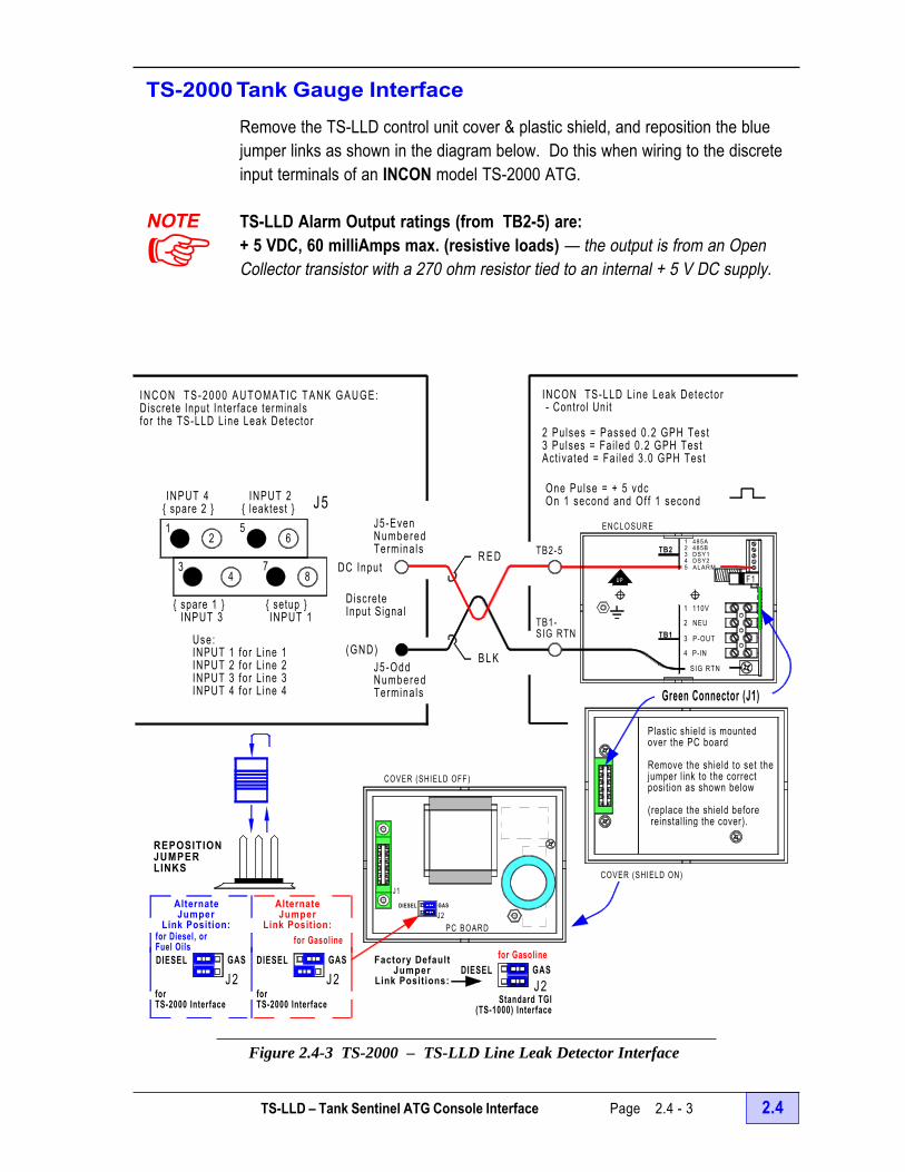
TS-LLD – Tank Sentinel ATG Console Interface Page 2.4 - 3 2.4
B L K
R E D
UP F1
TB1
1 485A2 485B3 DSY14 DSY25 ALARM
3 P-OUT
4 P-IN
2 NEU
1 110V
TB2
SIG RTN
7
6
43
1 5
INPUT 4{ spare 2 }
INPUT 2{ leaktest }
{ spare 1 } INPUT 3
{ setup } INPUT 1
8
2
J5
PC BOARD
GAS
J2DIESEL
J1
AlternateJumper
Link Position:
DIESEL GASDIESEL
J2
for Gasolinefor Diesel, orFuel Oils
AlternateJumper
Link Position:
GAS
J2
Green Connector (J1)
for Gasoline
J2GAS
REPOSITIONJUMPERLINKS
E N C L O S U R E
COVER (SHIELD ON)
COVER (SHIELD OFF)
TB1-SIG RTN
TB2-5
Use:INPUT 1 for L ine 1INPUT 2 for L ine 2INPUT 3 for L ine 3INPUT 4 for L ine 4
DiscreteInput Signal
(GND)
J5-Even Numbered Termina ls
J5 -OddNumbered Termina ls
DC Input
INCON TS-LLD L ine Leak Detec tor - Control Unit
2 Pu lses = Passed 0 .2 GPH Test3 Pulses = Fa i led 0 .2 GPH TestAct ivated = Fai led 3.0 GPH Test
for TS-2000 Interface
forTS-2000 Interface Standard TGI
(TS-1000) Interface
I N C O N T S - 2 0 0 0 A U T O M A T I C T A N K G A U G E :Discrete Input Inter face terminalsfor the TS-LLD L ine Leak Detector
One Pulse = + 5 vdcOn 1 second and Of f 1 second
DIESELFactory Default
JumperLink Positions:
Plastic shield is mountedover the PC board
Remove the shield to set the jumper l ink to the correct posit ion as shown below
(replace the shield before reinstall ing the cover).
TS-2000 Tank Gauge InterfaceRemove the TS-LLD control unit cover & plastic shield, and reposition the bluejumper links as shown in the diagram below. Do this when wiring to the discreteinput terminals of an INCON model TS-2000 ATG.
TS-LLD Alarm Output ratings (from TB2-5) are:+ 5 VDC, 60 milliAmps max. (resistive loads) — the output is from an OpenCollector transistor with a 270 ohm resistor tied to an internal + 5 V DC supply.
Figure 2.4-3 TS-2000 – TS-LLD Line Leak Detector Interface
NOTE
+

2.4 Page 2.4 - 4 TS-LLD INSTALLATION GUIDE
Programming the TS-2000
Alarm Relays
From ALARM RELAYS setup menu, select YES for LN LEAK RY1 to activate theaudible alarm inside of the console should a line leak occur. Select YES for LNLEAK RY2 to control an external device that is wired to these contacts.
Alarm Reports
From SYSTEM setup menu, enable Report Alarms to have alarm reports printoutautomatically at the console report printer. As with the TS-1000, Line TestReports and Line Test History Reports can be printed using the report key (seeprevieous page for examples).
TS-1001 / TS-2001 LLDI InterfaceThe Line Leak Detector Interface to these console uses a 4 conductor, 22 AWG,communications grade cable for the RS-485 protocol. See Figures 2.4-4 and2.4-5 for additional details.
See the TS-1001 / TS-2001 SetupProgramming Guide (P/N 000-1053)for programming details and availablereports.
Many line-related reports can beprinted at the console by using thereport key. See the TS-1001 /TS-2001 Sample Reports Document(P/N 000-1394) for Line – Test,Diagnostic, and History Reports.Also, in the sample reports document,see Line Alarm Reports for active linealarms, cleared line alarms, or linealarm history reports.240 AC POWER WIRING Trough Only
Motor Control Panels ( Relay Boxes - or - Starters )
Communicat ions Wir ing Trough Only
or
Figure 2.4-4 TS-1001 / TS-2001 LLDI Typical Connecting Hardware Layout

TS-LLD – Tank Sentinel ATG Console Interface Page 2.4 - 5 2.4
NOTE:1) CAUTION BEFORE attempting thisinstallation: Read and reference the TS-LLD Manualabout Safety, and CU Installation (and wiring steps).
2) WARNING Avoid electrical shock hazards —Turn off and disconnect all power to the pumps anddispensers before wiring at the TS-LLD Control Units.
3) Up to four TS-LLD Control Units ( CUs ) can beinterfaced to the TS-1001 console and up to eight CUscan be interfaced to the TS-2001 console.
Figure 2.4-5 TS-1001 / TS-2001 LLDI Wiring Diagram
TANK / LINE #2TS-LLD CU #2:
TB2-3 DSY1
TB1-SIG RTN
TB2-4 DSY2
TB2-2 485B
TB2-1 485A
CU #2
CU #1
1 485A2 485B3 DSY14 DSY25 A L A R M
SIG RTN
4 P- IN
3 P-OUT
2 NEU
1 110V
TS-LLD Control Unit (CU) box
TS-1001 / 2001 CONSOLETS-LLD INTERFACE TERMINALS AT J13:
DSY CONTROL UNIT I .D. LINE
S. RTN RS-485 COMMUNICATIONS SIGNAL RETURN
485B COMM LINE
485A COMM LINE
TB2-3 DSY1
TB1-SIG RTN
TB2-4 DSY2
TANK / LINE #1TS-LLD CU #1:
TB2-2 485B
TB2-1 485A
F1
1 485A2 485B3 DSY14 DSY25 ALARM
4 P-IN
SIG RTN
TB1
TB2
Enlarged ViewTS-LLD Control Unit (CU)
Interface Terminals:
TB1
UP
G N D
TB2
TB2-4 DSY2
TB2-3 DSY1
TB1-SIG RTN
TANK / LINE #3TS-LLD CU #3:
TB2-2 485B
TB2-1 485A
TB2-3 DSY1
TB1-SIG RTN
TB2-4 DSY2
JUMPERNEEDEDAT LAST UNIT ONLY
LAST TANK / LINE #NTS-LLD CU #N:
TB2-2 485B
TB2-1 485A
.. .NOTE --- DO NOT RUN COMMUNICAT IONSCABLE IN SAME CONDUIT AS L INE VOLTAGE WIRES.
last CU #N
CU #3
THIS SHIELD MUST BE IN PLACE BEFORE THE COVER IS RE-INSTALLED.
GREEN CONNECTOR (J1)
TS-LLD CU cover (back view)
COMMUNICATIONS CABLE: 22 AWG, 4 CONDUCTOR. . .
F1
W A R N I N G: AVOID ELECTRICAL SHOCK HAZARDS.EXTERNAL POWER SOUCES MAY BE PRESENT - LOCATE AND DISCONNECT ALL EXTERNAL POWERSOURCES BEFORE WIRING OR SERVICING THESE CIRCUITS.
TS-LLDI ( Line Leak Detector Interface )
TB1-SIG RTN
TB2-1 (485A)TB2-2 (485B)TB2-3 (DSY 1)
Enlarged View of Terminal Strip # J13

2.4 Page 2.4 - 6 TS-LLD INSTALLATION GUIDE
— Your Notes —
— v —

Testing the System After Installation Page 2.5 - 1 2.5
2.5 After Installation – Steps &Testing
After Installation Steps & Testing (follow steps in order):1) Make sure that all wiring is checked – completed – and correct, that all electrical
box covers are reinstalled, and that all personnel are clear. Surround the LSU and1/4 inch pipe plug fittings with absorbent. Remove safety tags and lockouts fromthe submersible pump circuit breakers at the electrical panel and then reapplypower (turn the circuit breakers on).
2) Immediately after a power-up, the control unit will display several numbers for afew seconds. Verify that the following is displayed:
nn (2 digit software version number [ Ver # ] of the CU ...after any power-up),
NN (2 digit Ver # of the LSU ...after second and subsequent power-ups),
DD (the total number of days since the last 0.2 monthly leak test passed. Thiswill show the current day count or a 00 for new installations).
3) Verify that the Line Leak Test light is on. The system should automatically starta 0.2 gph line leak test after power-up, or whenever the day count changes at thedisplay. The submersible pump is turned on at various times during a test to keepthe line pressurized. See Chapter 3 for operation and testing.
4) Verify that the Line Leak Detector, and the 1/4 inch NPT pipe plug (at the TankTest port) are not leaking product around these threads. If there is a leak, then:
a) Power down (turn off and lockout all power again) — see Chapter 2.1
b) Clean the pump housing with absorbent rags
c) Retighten the pipe plug / the line leak detector again. Follow the installationsteps and diagrams shown in Chapter 2.2 in reverse (from Step # 11 to Step# 5), and then forward again (from Step # 5).
d) Repeat steps 1) through 4 c) above until the pump housing is free of leaks.Remove the absorbent and properly dispose of these materials.
CAUTION Avoid damaging the MI Cable – loosen the compression fitting,disconnect and straighten the MI Cable before tightening/loosening the LSU.
Contents:• After Installation Steps / Testing• Important Warranty Information• Important Customer Documentation

2.5 Page 2.5 - 2 TS-LLD INSTALLATION GUIDE
After Installation Steps (continued... )5) Push the control unit RESET - TEST button momentarily to test the system
operation. Verify that the:
a) Line Leak Test light goes out when the RESET - TEST button is pushed
b) An 88 is displayed while the button is held down (indicating that the system isokay, and that all display segments are okay).
Do not hold the TEST push-button down longer than four seconds, otherwise a0.1 gph manual (annual precision) line leak test will start.
6) Recommended – dispense a small amount of product (a gallon or so) from eachdispenser to remove air that may be trapped in line during installation or service.Note that air trapped in the line may initially cause false alarms.
7) Verify that leak tests run and finish (Line Leak Test light turns on about 30seconds after a dispense and indicates that automatic 3 gph and 0.2 gph line leaktests are running). The Line Leak Test light will go out when these tests finish (15minutes to 4 hours later if dispensing is prevented... 1 hour is typical). Note: thelight will also go out when a test is aborted (by pushing RESET-TEST), or when adispense occurs.
8) Follow-up with the Customer within 30 days and ask for a display reading. If thedays are counting up instruct them to leave the pump breakers on 24 hours a day(so tests can finish during quiet times / after normal business hours).
Important — Warranty Registration
After installation, completely fill-out the postage-paid Warranty Registration Card.Have the customer / owner / manager sign this card give a copy to him. Finally,fax a copy or mail the original card back to INCON. Please make certain that youfill out the CU & LSU serial numbers.
Important — Customer Documentation
r Leave a copy of the completed Warranty Registration card with the customer.
r Leave copies of the TS-LLD Quick Reference Guide with the customer (INCONP/N 000-1447 — latest revision). One is supplied with each TS-LLD system.
r Provide the name(s), phone number(s) of the local Inspection Agency and otherapplicable information, instructions and regulations should a line leak be detected.
r Provide the name(s) and phone number(s) of the local Distributor and Serviceprovider for the future use and reference by the customer.
— v —

System Operation & Testing Page 3 - 1 3
3 TS-LLD System Operation & Testing
System OperationThe TS-LLD system can perform three different pressurized line leak tests, twoof which run automatically. The automatic line leak tests are: a gross 3.0 gphhourly test, and a standard 0.2 gph monthly-compliance test. The third test is aprecision 0.1 gph annual test that must be started manually at the control unit...the 0.1 annual test is also known as a manual test.
A Quick Reference Guide is provided with every TS-LLD system. It was designedspecifically for use by your customer at his station. Inform your customer to keepa log of all alarm and error codes. This log could be FAXed to you and wouldprove to be very useful diagnostic tool. Distributors and Installers: you mayorder more guides by contacting INCON and asking for part number 000-1447 orfor 000-1482, which is a color-laminated version. Certain restrictions may apply.
Need Help ?Call INCON Technical Service @ 1-800-984-6266 (or FAX: 1-207-282-9002) forhelp with leak alarms, or diagnostic codes. Also, please call if alarms, warnings,or error codes occur frequently or repeatedly.
DANGER This line leak detector may start the pump at any time during a lineleak test to maintain fuel line pressurize. Avoid Fire, Explosion hazards, andElectrical shock hazards... make sure that all dispenser and submersiblepump power is turned off / locked out before attempting any service (such as:replacing fuel line filters). Inspect the copper Mineral Insulated Cable (MI Cable)at the Leak Sensing Unit for damage, kinks, or breakage. Make sure to do thisafter any installation or service is done in the containment sump / pump head andBEFORE power is applied. See Chapter.Section 2.2 in this manual aboutinstallation and inspection. Never apply power if the MI Cable is damaged !
Contents:• System Operation• Normal Displays (Day Counts, Diagnostic Codes)• Fault displays (Test fails, Monthly Compliance Warnings)• Indicator lights, RESET-TEST button USE• Starting a 0.1 Manual Precision Leak Test• Normal Operation (Sequence of Events)• Out of Compliance (Dispensing Disabled)• Frequently Asked Questions• What to do: When a Leak Test Fails ? (Leak is Detected)

3 Page 3 - 2 TS-LLD INSTALLATION GUIDE
RESETTEST
TS-LLDLINE LEAK DETECTOR
LINELEAKTEST
LINELEAKDETECTED
DISPLAY FUNCTION
NORMAL: DAYS SINCE MONTHLY LEAK TEST PASSED
FLASHING: 1 = FAILED ANNUAL (0.1 GPH) LEAK TEST2 = FAILED MONTHLY (0.2 GPH) LEAK TEST3 = FAILED HOURLY (3.0 GPH) LEAK TEST
29 – 32 = MONTHLY COMPLIANCE WARNING33 – 87 = ERROR CODES
88 = SYSTEM OK (PRESS TEST TO ACTIVATE)
PRESS RESET TO CLEAR ALARM
PRESS TEST FOR 5 SECONDS TO RUN ANNUAL TEST
INTELLIGENT CONTROLS, INC.
CU Component Location & Function
~~
~
~
~
À
Á
Ã
Â
Ä
Figure 3-1: Control Unit Cover – Component Location
Control Unit (CU) Display
Line Leak Test light (shown testing)
Line Leak Detected light
Display Functions, Codes &Concise Instructions
Reset Test touch button
Control Unit Display ÀThe 2-digit, 7 segment LED will display: day-counts, RESET-TEST touch-button diagnostic codes,and possibly Diagnostic Codes Between 0.2 Gph Test-cycles when the system is operatingnormally. The display will also rapidly flash: line leak detected / test-fail alarm codes, monthly-compliance warning codes, or error codes when faults occur.
Normal Displays ( on steady / solid )
Day CountsOrdinarily, the display shows the total number of days since the last 0.2 gphmonthly-compliance test passed. The day count is on steady (not flashing) andadvances one day for every 24 hours that a monthly test does not finish with apassed result. The normal display range is from 00 (zero days) to 28 days, i.e.00 = zero days (a 0.2 gph test has passed within the last 24 hours), up to
28 = twenty eight days have elapsed since the last monthly-compliance testpassed (also see Monthly-Compliance Warning which begins on Day # 29)
Fault Displays ( rapidly Flashing – twice per second )
Alarms, Warnings, and Error codes, ranging from 80 to 85, are displayed when thefollowing conditions occur. See Chapter 6.1 & 6.2 about Error Codes
a. Line Leak Test Failure – Flashing Leak Alarm CodesIdentifies the minimum leak rate detected (in gallons per hour)1 0.1 gph line leak was detected (annual precision test failed)2 0.2 gph line leak was detected (monthly compliance test failed)3 3 gph line leak was detected (hourly gross leak test failed)

System Operation & Testing Page 3 - 3 3
When a Leak Test Fails / Line Leak is Detected:1) The display flashes one of the single-digit Line Leak test-fail Alarm Codes
2) Dispensing is disabled for that line / product, pump is turned off (can be reset)
3) The Line Leak Detected light flashes continuously and keeps flashing until anothertest of equal or greater precision passes... this light cannot be reset or turned-off
4) The leak test fail / line leak alarm can be printed out or faxed i f the LLD has beenoptionally interfaced with an INCON ATG
b. Monthly-Compliance Warning – Flashing Day CodesA 0.2 gph monthly-compliance test still hasn’t passed. Up to four flashing warningcodes can displayed when the line is nearly out of compliance with State andLocal regulations (a 0.2 gph test must pass each month).
29 produced on Day number 29 (first monthly-compliance warning)30 produced on Day number 30 (second warning)31 produced on Day number 31 (third warning)32 produced on Day number 32 (fourth and last warning)On day 33 a Flashing 84 Error-Code is produced, which causes a hardshutdown that can’t be overridden by a reset... no further dispensing is alloweduntil a 0.2 gph test passes (see Out of Compliance later in this Chapter).
Indications:1) A flashing Monthly-Compliance Day Code Warning is displayed (see b. above)
2) Dispensing stops but can resume if the Reset Test button is pushed (permits up to24 hours of additional dispensing or until the day-count changes to the next day)
Recommendation:Prevent dispensing and let the test finish. The monthly compliance waring mayindicate a malfunction within the system and may require a service call to the site.
c. Flashing Display Error CodesThe following error codes may occur... see Chapter 6.1 & 6.2 for more details.
80 A dispense occurred during a manual Annual Leak Test81 A component failed within the LSU82 A leak test pass or fail could not be determined (result = indeterminate)83 The LSU is not communicating with the CU84 The line is out of compliance (a monthly compliance test has not passed in
the last 33 days)... no dispensing is allowed until a monthly test passes.85 LSU screen / flow tube is blocked and requires cleaning

3 Page 3 - 4 TS-LLD INSTALLATION GUIDE
CU Component Location & Function (Continued... )
Line Leak Test light ÁTurns on when any line leak test starts and stays on during the entire test. The lightonly turns off when:
1) a test finishes
2) a dispense occurs
3) the Reset Test button is pushed
Line Leak Detected light ÂFlashes on and off continuously when a line leak test fails. This light will continue toflash until another test – of equal or greater precision – finally passes.
Display Functions, Codes & Concise Instructions Ã
RESET TEST touch button Ä ... press to:• Abort, Stop, or Cancel any line leak test (the Line Leak Test light Á will also
turn off when the RESET TEST is pushed)
• Clear any flashing Error codes and Enable product dispensing (except theFlashing 83 or 84 Error codes)... error codes will reappear if the problem remains
• Reset and restart automatic line leak testing (the leak detected light  cannotbe reset if a leak was detected)... Automatic Line Leak Tests resume after productis dispensed.
• Perform a Self-Test (one push displays an 88) see Chapter - Section 6.1
• Display diagnostic codes (see Chapter - Section 6.1)
• Start a manual, 0.1 gph annual precision line leak test
Display Diagnostic Test Codes:See Chapter - Section 6.1 for directions about Diagnostic Display Test Codes
Starting a Manual 0.1 gph Precision Leak Test
Requirements:Prevent dispensing / bag dispenser during this time. The manual test needs 4hours of quiet-time BEFORE it is started, and takes about 13 minutes to finish.
Definition: quiet-time is the inactive period –between– product dispensing
NOTE+
NOTE+

System Operation & Testing Page 3 - 5 3
A Flashing 80 Error code will be produced, and dispensing inhibited, if a dispenseis attempted when an annual test is running. This error can be cleared by pushingthe RESET-TEST touch button.
How to Start a Manual TestPress and hold the RESET-TEST touch button down more than 5 seconds untilthe Line Leak Test light Á turns on. Do not hold the reset-test button downlonger than 4 seconds unless a manual test is desired.
Normal Operation – Sequence of Events / Steps
1.) Product Dispense – Begin ( dispenser: nozzle out / lever up / switch on )a) Aborts / Cancels / Stops any line leak test that is running, and turns off the Line
Leak Test light Á – or –
b) Perform a functional self-check and allow product dispensing IF okay – or –
c) Prevent dispensing (turn the pump off) IF an error or fault was detected
2.) Product Dispense – End ( dispenser: nozzle in / lever down / switch off )After a short delay the 3.0 gph line leak test starts.
3.) The 3.0 gph Gross Hourly TestStarts automatically — after every dispense and before a 0.2 gph test, or before a0.1 gph test.a) The 3.0 gph hourly test takes about 3 minutes of quiet-time to finish
b) The Line Leak Test light Á stays on throughout this test
c) The process will begin again from Step 1.) when Product is Dispensed
4.) The 0.2 gph Monthly-Compliance Testa) Requires from 13 minutes – to – 4 hours of uninterrupted quiet-time to finish
The total time required to complete the monthly test depends on the specificconditions at the site and within the line. Tests finish rather quickly when anobvious pass or fail condition exists. Tests times are lengthened when a moredetailed analysis is required.
b) The 0.2 gph test is made up of one or more, 13-minute test-cycles. )c) The Line Leak Test light Á stays on throughout the entire test
NOTE+
NOTE+

3 Page 3 - 6 TS-LLD INSTALLATION GUIDE
Normal Operation – Sequence of Events / Steps (Continued... )
A 0.2 gph Test Automatically Starts:1) when the system is powered up (as is the case in new installations, the CU
attempts 0.2 gph leak tests until one finally passes).
2) when a 3 gph leak test passes (after a dispense) unless another 0.2 gph test haspassed within the last 24 hours (when this happens: the day-count is reset anddisplays a 00, and the Line Leak Test light only turns on for about 3 minutes —during 3 gph leak tests)
3) when the display advances to the next day (the CU waits 24 hours before startinganother monthly-compliance test)
4) when a line is Out-of-Compliance
Out of ComplianceIf a 0.2 gph Monthly-Compliance line leak test does not pass by day 33, then theline will be Out of Compliance. Three things happen when a line is Out ofCompliance. These are:
1) a Flashing 84 error code is displayed,
2) the Line Leak Test light turns on because a 0.2 gph monthly compliance test isautomatically started, and
3) product dispensing is disabled (stopped / shutdown).
None of these events can be stopped, reversed, or reset. The monthly leaktest must pass (and be in Compliance) before product can be dispensedagain. This test should finish in about 1 hour and reset the day count to 00 andturn the Line Leak Test light off. See the Troubleshooting Guide in Chapter 6.2 ofthis manual about flashing 84 alarm error codes if this test does not finish.

System Operation & Testing Page 3 - 7 3
Frequently Asked Questions
Why do Days Count Up ?A monthly-compliance test has not passed. This can be caused by very frequentdispensing (the quiet-time between product dispensing is too short for the test tofinish). This may happen in very busy stations or when the pump power is turnedoff after business hours. Also see Chapter 6.2 in this manual.
Why do Error Codes 29, 30, 31, or 32 Appear ?See Monthly Compliance Warnings and Why Days Count Up earlier in thisChapter.
How do I Display the Last Alarm or Error Code ?See how to Display Diagnostic Test Codes in Chapter 6.1 by using the RESETTEST touch button
How do I Reset Flashing Error Codes ?How do I Allow Dispensing ?How do I Clear Flashing Codes ?
First find out what the Flashing Code represents (Leak Alarm, Error, or Warning).The display À will rapidly Flash an Alarm or Error Code twice per second wheneither line leak or error is detected, but only the Line Leak Detected light  willrapidly Flash when a line leak alarm occurs. In this Chapter see: How to Verify aLeak — when a leak Alarm is produced, or see using the RESET TEST touchbutton and its operation.
Why can’t I Reset and Dispense ?See Chapter 6.2, for Alarms, Errors, and Warnings that disable dispensing. AnError Code 84 cannot be reset because the line is Out of Compliance. See theOut of Compliance discussion earlier in this Chapter.
How do I Verify a Leak ? Does it Exist ? or was it a False Alarm ?See Chapter 4 about Line Leak Detection, and this Chapter about using theRESET TEST button. Remember that the Line Leak Detected Light  willcontinue to flash on and off until another test, of equal or greater precision finallydoes pass.
Visually inspect the sump and dispenser areas whenever the TS-LLD reportsa leak !
Continued next page...

3 Page 3 - 8 TS-LLD INSTALLATION GUIDE
Frequently Asked Questions (Continued... )
How do I Start a Manual Test ?See this Chapter about using the RESET-TEST button to Start a 0.1 gph AnnualPrecision Leak Test (also see the test Requirements before you start it).
How Often Should the Manual Test be Run ?See Chapter 4 about Line Leak Detection and INCONs recommended frequency(the manual test cannot be started when a flashing 84 error code is displayed).
What Should I Do:
When a 3 gph Leak Test Fails / Gross Leak is Detected ?The display shows a flashing 3 Alarm code — immediately follow theinstructions in Chapter 4
When a 0.2 gph Leak Test Fails / Leak is Detected ?The display shows a flashing 2 Alarm code — follow the instructions inChapter 4
When a 0.1 gph Annual Precision Leak Test Fails / Leak is Detected ?The display shows a flashing 1 Alarm code — follow the instructions in Chapter 4
Visually inspect the sump and dispenser areas whenever the TS-LLD reportsa leak !
— v —
!

Line Leak Detection Page 4 - 1 4
4 TS-LLD Line Leak Detection
When a Line Leak is DetectedThe TS-LLD line leak detection system: disables the Submerged Turbine Pump,flashes the Line Leak Detected light, and displays a flashing test-fail Alarm codewhen a line leak test fails.
CAUTION DO NOT excavate and repair a fuel-line solely on the basis of asingle alarm. Confirm the presence of a leak before attempting any repairs !
Leak tests occasionally fail when no leaks actually exist because of: product lineinstability, thermal contractions within the line, or pump / vapor recovery systemmalfunction. Air trapped within the line may also cause false leak alarms (this isespecially true after new installations / maintenance / service). See Chapter 2.4...has product been dispensed after installation or service ? When was the lastmaintenance / service done ?
Steps to take When a Line Leak is Detected:
1) Identify what type of leak was detected... Flashing test-failed Alarm codes:3 = 3 gph leak = hourly test failed (gross / large leak)2 = 0.2 gph leak = monthly-compliance test failed1 = precision 0.1 gph leak = annual / manual test failed
2) Stop / Prevent dispensing (bag or tape poly over dispenser and dispense lever).3) Inspect the piping system, dispenser, fittings, and hoses for obvious leaks. Open
the dispenser enclosure, and inspect the fittings and fuel filter for leaks (especiallyif maintenance or service was done recently).
4) If no leaks are found during inspection, then start another leak test to verifythe previous failure (The Line Leak Detected light will keep flashing and will notturn off until another test of equal or greater precision passes).Start another test (same type that originally failed as identified in step one)... SeeChapter 3 about the requirements of and how to start a 0.1 manual test – or –to start automatic 3 gph and 0.2 gph line leak tests: push the Reset Test buttonto clear a failed test and simulate a dispense (see the next page about this).
NOTE+
Contents:• When a Line Leak is Detected• Steps to take When a Line Leak is Detected• How Often Should a Manual 0.1 gph Test be Run ?• Need Help (with line test failures) ?

4 Page 4 - 2 TS-LLD INSTALLATION GUIDE
Step 4 (continued... )
Simulate a dispense by – move the dispense lever up and wait a few secondsafter the pump has turned on, and then move the dispense lever down.
5) Prevent dispensing while this test is running (bag or tape poly over thedispenser and dispense lever)
6) If a leak is found, or if the second line leak test also fails, then:a) Shut off all power to the affected pump and dispenser & contact INCON
Technical service
b) Take corrective action in accordance with local, State, and Federal regulations
c) Contact the local inspection agency, and follow all procedures andinstructions as required by State Laws and Regulations.
WARNING When a line leak is detected, it is the station owner’s obligationto contact his local inspection agency and comply with the reporting and procedurerequirements of local / State / Federal Laws and Regulations. These must befollowed explicitly. Serious legal, health and safety hazards could result from nottaking the proper action. Where the codes and regulations conflict with thismanual, follow the regulations.
The site (station owner, shift manager(s), and personnel) must have access to theImportant — Customer Documentation as listed in Chapter.Section # 2.4. Thisdata is required for their reference (our valued customer). TIP Also keep acopy of this documentation for your future reference.
How Often Should a Manual 0.1 gph Test be Run ?
State and local regulations will dictate the need for and frequency of the 0.1 gphannual test and inspections. Make sure you and the site are aware of the issuesand requirements for compliance testing and inspections.
Need help ?Contact INCON Technical Service at 1-800-984-6266 (FAX #: 207-282-9002) forhelp with: a Line Leak Test failure, repeated Line Leak Test failures, or multipleLine Leak Test failures. Also see Chapter 3, for additional information aboutSystem Operation & Testing, and Chapter 6.1 & 6.2 for information about Alarm –Error Codes, & Troubleshooting.
— v —
NOTE+

Maintenance & Service Page 5 - 1 5
5 TS-LLD Maintenance & Service
This chapter contains instructions ranging from routine cleaning to maintenanceinspections, replacement instructions, and maintenance frequency... A/R meansas required. Replacement part numbers are shown here as well.
Cleaning the Control UnitClean the Control Unit (CU) exterior with a soft sponge or cloth that is slightlydampened with a solution of water and mild detergent – A/R by Customer
DANGER Fire, Explosion, & Electrical Shock Hazard. Before installing,servicing, or working on this equipment, make sure all submersible pumppower and pump relay coil / dispenser power is turned off & locked out atthe electrical panel. Prevent automatic or unauthorized pump start-ups, spillsfrom pressurized lines, and electrical shocks. See Chapter 2.1 and follow allSafety advise.
Control Unit Replacement PartsItems Frequency = A/R Replacement Part Numbersa) Fuse F1 ....................................................... P/N = 430-0010
b) Terminal Board ....................................................... P/N = 010-0072
c) Replacement cover faceplate (with new Software ) ........... P/N = TS-FPU
d) Entire Control Unit US.................................................. P/N = TS-CUCanadian ....................................... P/N = TS-CU/C
Are the CU box label and cover label correctly marked with the product and line #?Are the jumper links behind the cover (at J2) correctly configured ? ReferenceChapter 2.3 for product & jumper link configuration(s).
Pump Relay Control Box Replacement PartsItems Frequency = A/R Replacement Part NumbersLine Filter Capacitor @ Pump Relay (Motor Control) Box ........ P/N = 020-0028
...
Contents:• Cleaning the Control Unit• Control Unit Replacement Parts• Rump Relay Control Box Replacement Parts• Leak Sensing Unit Replacement Parts• LSU Removal for Service / Inspection and Cleaning• After Maintenance or Service DO
NOTE+

5 Page 5 - 2 TS-LLD INSTALLATION GUIDE
Leak Sensing Unit (LSU) Adapters & Replacement PartsItems Frequency = A/R Replacement Part Numbersa) M I Cable Adapter 2 inch NPT ......................................... P/N = TS-RJ
b) M I Cable Adapter 3 inch Straight Thread ....................... P/N = TS-FEc) Leak Sensing Unit USA .................................................. P/N = TS-LSUd) Leak Sensing Unit Canadian ........................................... P/N = TS-LSU/Ce) Leak Sensing Unit Screen .................................................. P/N = 270-0002f) Leak Sensing Unit O-Ring .................................................. P/N = 250-0048
LSU Removal for Service / Inspection and Cleaning
The LSU is removed or replaced whenever the following service steps are done.Review Chapters 2.0 through 2.2 before removing or replacing a LSU.
1) With all pump power off and line-pressure relieved: follow the installation steps& diagrams shown in Chapter 2.2 in reverse order to remove the LSU.
2) Carefully straighten the MI Cable enough to provide clearance from othercomponents while the LSU is being unscrewed (removed) from the pump.
3) Clean the LSU Screen and Flow Tube ......when aflashing 85 Error Code is displayed at the CU –replace the Screen as required
4) Inspect LSU O-Ring ......when the LSU screen iscleaned – replace O-Ring as required. The LSUO-Rings are made from a special material that areUL rated – use no substitutes. Install only genuineINCON LSU O-Rings. (Also see Appendix A aboutApplicable Liquid Products.)
5) Reinstall / Install the Leak Sensing Unit per stepsshown in Chapter 2.2
6) Inspect the M I Cable at the LSU for damage, kinks, sharp bends, and breaksbefore reapplying power ......whenever the containment sump has beenaccessed ......and after all maintenance or service of the Submerged TurbinePump or other related components (such as the piping system).
7) Replace the LSU per Chapter 2.2 – before power-up ......whenever the MI Cablehas been damaged, or when the LSU has malfunctioned / become inoperable.
After Maintenance or Service DO –Make sure that the system is operating properly ! See Chapters 2.4 and 3 forinformation about System Operation and Testing, and Chapters 6.1 & 6.2 forabout Error Codes & Troubleshooting.
— v —
LSU O-Ring
LSU Screen
LSU Leak Sensing Flow Tube(outlet at bottom)
Bottom & Side Views

Service and Factory Support Page 6.0 - 1 6.0
6.0 Service & Factory Support
Where to Find HelpChapter 6 is divided into four problem solving sections for your reference. Theseare:
Service and Factory Support Section 6.0Alarms and Error Codes Section 6.1Trouble Shooting Guide Section 6.2Warranty Section 6.3
Refer to the Table of Contents and Figures in this manual to find where otherhelpful information is located.
A Quick Reference Guide is provided with every TS-LLD system. It wasspecifically designed for use by your customer at his station. He has beeninstructed to keep a log of all alarm and error codes. This log could be FAXed toyou and would prove to be very useful diagnostic tool. Distributors andInstallers: you may order more guides by contacting INCON and asking for partnumber 000-1447. Certain restrictions may apply.
ServiceOnly authorized service technicians / organizations are permitted to install andwork on this equipment. Contact INCON for authorized service technicians in yourarea.
Continued next page...
!
Contents:• Where to Find Help• Service• Factory Support• Phone & Fax numbers• INCON Office Hours:• Before calling INCON:
NOTE+
• Return Shipments• Warranty Registration Card
(blank... can be copied, filled-in the copy and FAX back to INCON)

6.0 Page 6.0 - 2 TS-LLD INSTALLATION GUIDE
Factory SupportNeed Help ? Call INCON Technical Service for help with leak alarms, ordiagnostic codes. Also, please call if alarms, warnings, or error codes occurfrequently or repeatedly.
Phone & Fax numbers:
Sales Technical ServicePhone: (800) 872-3455 ** Phone: (800) 984-6266
Fax: (207) 283-0158 Fax: (207) 282-9002
E-mail:
[email protected] [email protected]
** Technical Service Help is available 24 hours a day
INCON Office Hours:8 a.m. to 5 p.m. EST Monday through Friday
Before calling INCON:• Have the CU or LSU Serial Numbers on hand for units you’re having trouble with.
• The TS-LLD Warranty Registration Card should have this information (it shouldhave been filled-out completely and mailed or FAXed back to INCON afterinstallation). NOTE: The example Warranty Registration card on the next pagecan be copied and used for FAX in registration.
Return ShipmentsIf it should become necessary to return the LSU or CU to INCON please use theoriginal packaging materials if possible. Return shipping damage due toinadequate or inappropriate packaging is your responsibility. Make sure the return-goods shipment is insured.
Before returning anything to INCON, you must first obtain a Return MaterialAuthorization (RMA) number. Shipments of returned equipment, which have notbeen authorized, will be returned freight collect.
Call INCON Technical Service Department from the site for RMA numbers. Ourpersonnel will give you the correct shipping address, and provide other details andinstructions that you will need when you call for the RMA number.

Service and Factory Support Page 6.0 - 3 6.0
Warranty Registration Form: (copy, fill-in, & FAX Registration Form back to INCON)
TS-LLD Warranty Registration FormTelephone No. 1-800-984-6266 ♦♦♦♦♦ FAX No. 1-207-282-9002 000-1480 REV. C
Registration activates your warranty — mail, or Fax in today !
TS-LLDInstallation Date: Line # ofPurchased From: Dispenser / Manufacturer Type:Installers Name & Certificate Number:
Functional Element / age:Site Information:Company Name: Telephone No.Mgr. / Contact Name: Reg. hours of OperationStreet Address: Are blenders used ? Yes No
Is this an IST application ? Yes NoIs this a Big Flo ® pump ? Yes No
Turbine Pipe Type Size LengthProduct Pump Type & HP Steel
Reg. UL Mid. UL Prem. UL Red Jacket ® FiberglassDiesel #2 Fuel Oil Kerosine FE Petro™ Flexible (& below)Other Other ...manufacturer:
Write in, or tape-onSerial No. labels
here
LSU Serial No.CU Serial No.— Please print, or type —
TS-LLD
circle
circle
NO POSTAGENECESSARY
IF MAILEDIN THE
UNITED STATES
BUSINESS REPLY MAILFIRST-CLASS PERMIT NO. 12 SACO ME
POSTAGE WILL BE PAID BY THE ADDRESSEE
ATTN: TECHNICAL SERVICEINTELLIGENT CONTROLS INCPO BOX 638SACO ME 04072-9962
ENVIRONMENTAL CONTROLS DIV.SACO MAINE USA
BACK S
IDE
FRO
NT
SID
E

6.0 Page 6.0 - 4 TS-LLD INSTALLATION GUIDE
— Your Notes —
— v —

Test Fail Alarm & Error Codes Page 6.1 - 1 6.1
6.1 Test Fail Alarms, Warnings &Error Codes
Display CodesThe following Normal, Alarms, Warnings, and Error Codes are displayed at thecontrol unit at this publication date.
Normal Display Codes (on steady – not flashing)
DISPLAY CODE DESCRIPTION
00 to 28 Number of Days since a 0.2 gph monthly-compliance leak testpassed (00 = zero days, 09 = nine days). The display counts up(advances a day) for every 24 hours that the test has not finishedwith a passed result.
88 System OK... the control unit electronics and all segments of the2 digit display are working correctly.
Flashing Display Codes (Alarms, Warnings, and Error Codes)
Flashing Error Codes can occur in range from 80 to 85 only !DISPLAY CODE DESCRIPTION
1 Alarm 0.1 gph Annual (manual) Leak Test Failed
2 Alarm 0.2 gph Monthly-Compliance leak test Failed
3 Alarm 3 gph Hourly – gross – leak test Failed
29 – 32 Warning ! the line is almost out of compliance ! It has beennn days (represented by the flashing number) since the last 0.2gph Monthly-Compliance test passed. Also see 84 Error Code.
80 Error Manually started, 0.1 gph Annual precision leak test wasaborted... a dispense was attempted while the test was running
81 Error A component failed within the Leak Sensing Unit
82 Error Indeterminate 0.2 gph leak test result — the line was notthermally stable. This error will not disable dispensing and can beviewed when RESET-TEST is pushed 4 times.
Contents:• Normal Display Codes (on steady – not flashing)• Flashing Alarm, Warning, and Error Display Codes• Diagnostic Display Codes

6.1 Page 6.1 - 2 TS-LLD INSTALLATION GUIDE
Flashing Error Codes (continued... )
Flashing Error Codes can occur in range from 80 to 85 only !DISPLAY CODE DESCRIPTION
83 Error Leak Sensing Unit is not communicating with the ControlUnit
84 Error The line is Out of Compliance (it has been at least 33 dayssince the last 0.2 gph Monthly-Compliance test has passed.
85 Error Leak Sensing Unit requires service
Diagnostic Display CodesThese are obtained by repeatedly pressing the RESET button... DO NOT hold the TEST button
down longer than 4 seconds, otherwise a manual leak test will start.
First press:88 System OK... all 7 segments of the 2 digit display are on and are
working correctly when 88 is displayed (88 is solid/not flashing).
Second press:XX Solid or flashing number which represents the average tempera-
ture differential of the last 0.2 gph leak test. Record this numberfor assistance from INCON.
Third press:XX Solid or flashing number for the accumulated power reading of
the last 0.2 gph leak test (00 - 99 solid ...solid 99 represents anumber from 99 to 149 and flashing 99 represents a number from150 and above). Record this number for assistance from INCON.
Fourth press:XX Flashing number which represents the last flashing Leak
Detected Alarm code or Error code. Record this number forassistance from INCON.
— Your Notes —
— v —
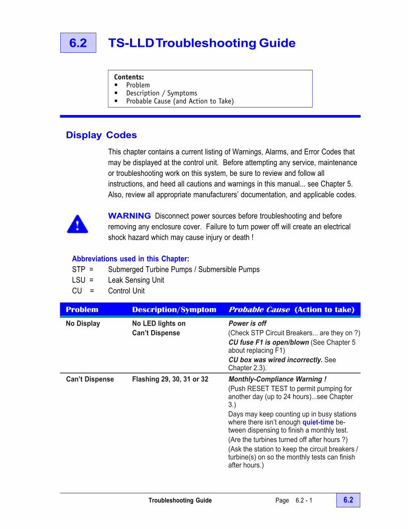
Troubleshooting Guide Page 6.2 - 1 6.2
6.2 TS-LLD Troubleshooting Guide
Display CodesThis chapter contains a current listing of Warnings, Alarms, and Error Codes thatmay be displayed at the control unit. Before attempting any service, maintenanceor troubleshooting work on this system, be sure to review and follow allinstructions, and heed all cautions and warnings in this manual... see Chapter 5.Also, review all appropriate manufacturers’ documentation, and applicable codes.
WARNING Disconnect power sources before troubleshooting and beforeremoving any enclosure cover. Failure to turn power off will create an electricalshock hazard which may cause injury or death !
Abbreviations used in this Chapter:STP = Submerged Turbine Pumps / Submersible PumpsLSU = Leak Sensing UnitCU = Control Unit
Problem Description/Symptom Probable Cause (Action to take)
No Display No LED lights on Power is offCan’t Dispense (Check STP Circuit Breakers... are they on ?)
CU fuse F1 is open/blown (See Chapter 5about replacing F1)CU box was wired incorrectly. SeeChapter 2.3).
Can’t Dispense Flashing 29, 30, 31 or 32 Monthly-Compliance Warning !(Push RESET TEST to permit pumping foranother day (up to 24 hours)...see Chapter3.)Days may keep counting up in busy stationswhere there isn’t enough quiet-time be-tween dispensing to finish a monthly test.(Are the turbines turned off after hours ?)(Ask the station to keep the circuit breakers /turbine(s) on so the monthly tests can finishafter hours.)
Contents:• Problem• Description / Symptoms• Probable Cause (and Action to Take)

6.2 Page 6.2 - 2 TS-LLD INSTALLATION GUIDE
Problem Description/Symptom Probable Cause (Action to take)
Can’t Dispense Flashing: 3, 2, or 1 RedJacket Functional Element – badFalse Leak Alarms & Leak Detected Light ON (check / replace)Multiple Nuisance Vapor Recovery system malfunctionAlarms (check / repair)
Check Valve leaking(check / replace)Air in lines(dispense product after installation to removeair from the lines)
Can’t Dispense Flashing: 3 3 gph (or greater) GROSS Line Leak !...& Leak Detected Light ON Test Failed (see Chapter 4 about the Steps
to take When a Line Leak is detected)Can’t Dispense Flashing: 2 Monthly 0.2 gph Line Leak / Test Failed
& Leak Detected Light ON (see Chapter 4 about the Steps to takeWhen a Line Leak is detected)
Can’t Dispense Flashing: 1 Annual 0.1 gph Manual Leak Test Failed& Leak Detected Light ON (see Chapter 4 about the Steps to take
When a Line Leak is detected)
Flashing Alarm Error Codes are limited to a range of 80 to 85 ONLY !
Can’t Dispense Flashing 80 Error Code A manual 0.1 Annual leak test wasaborted by an attempted dispense.(Push RESET to permit pumping when anannual test was unintentionally started – or –Do not hold the RESET TEST button downlonger than 4 seconds unless a manual testis intended. Bag the dispenser / preventdispensing during the test and for 4 hoursbefore starting a Annual leak test ...also seeChapter. 3)
Can’t Dispense Flashing 81 Error Code LSU internal component failure(Push TEST-RESET to permit dispensingonce again. Schedule service at this site.)
Counting Days Diagnostic Error Code 82 A 0.2 monthly leak test aborted becauseFlashing (when viewed) the line was not thermally stable
(A test will abort when the test result isindeterminate after 18 cycles... neither apass or fail result can be determined. Themonthly test will start again after anotherdispense. Call INCON when days count upand when this Diagnostic Error Code isconsistently displayed.)
NOTE+

Troubleshooting Guide Page 6.2 - 3 6.2
Problem Description/Symptom Probable Cause (Action to take)
Can’t Dispense Flashing 83 Error Code No communications between LSUand CU(New installations: Check for loose wiring, orwiring errors, or omissions )Previously functioning systems — PressRESET to allow dispensing for another 4hours and call INCON Tech Service)
Can’t Dispense Flashing 84 Error Code The line is Out-of-Compliance becausea Monthly Compliance Test has notpassed in the last 33 days)(This Error Code cannot be reset by pressingthe RESET TEST button — product dis-pensing is not allowed when Out ofCompliance. A new 0.2 gph test automati-cally starts when this Error is displayed.Prevent dispensing and give the test time tofinish { from 13 minutes to 4 hours later }.This may happen in extremely busy stations.Are the turbines turned-off after hours ?Ask the station to keep the circuit breakers /turbines on so tests can finish after hours.Call INCON if the Leak Test does not finish.A valve seat may have failed at the LSUwhich would cause indeterminate test result(neither pass or fail), and will cause the daysto count up. )
Can’t Dispense Flashing 85 Error Code The LSU requires service.(Press RESET to allow dispensing foranother 4 hours. Schedule service when thiserror occurs repeatedly.See Chapters about Safety, Installation,Maintenance and Testing and call INCON)
Please call our service department for tips and solutions to other problems not addressed atthe time of this publication. Also, call INCON technical service when warnings, alarms, orerror codes happen often or repeat often. Also, see Chapter 6.0 before calling INCON.
6.2 Page 6.2 - 4 TS-LLD INSTALLATION GUIDE
— Your Notes —
— v —

Warranty Page 6.3 - 1 6.3
6.3 TS-LLD Warranty & Terms
WARRANTY
INCON ® warrants to the original end user of the TS-LLD line leakdetector system that any part thereof will be free of defects of materialand workmanship for 12 months of operation from the date of installationas indicated on the mail-in TS-LLD Warranty Registration Card (orfacsimile thereof), or 18 months from the date of shipment, whicheveroccurs first. During this period INCON will, at its option, modify, repair orreplace defective products at no charge. This is a materials only warranty,and does not include labor or service charges.
INCON will not accept shipments of returned products without a ReturnMaterial Authorization (RMA) number. RMA numbers are obtained bycontacting INCON Technical Service Department — NO RMAs will begiven without the unit Serial Number(s). Returned material remains theproperty of the buyer until replaced or repaired.
Warranty Disclaimer and Limitation of Liability
There are no warranties which extend beyond those expressly set forthin this document. INCON disclaims and excludes all implied warrantiesincluding without limitation those pertaining to merchantability and fitnessfor a particular purpose.
INCON expressly disclaims and excludes any liability for consequentialor incidental damages for breach of any expressed or implied warrantyarising in connection with this product or this manual, including withoutlimitation, purchaser’s loss of stored liquids, or damage to the ground,underground or environment, whether arising under theories of tort,negligence, strict liability, contract or otherwise.
After installation, make sure to sign and return the completedWarranty Registration card to INCON. This form validates theexpress warranty stated here ! (See page 6.0 - 3 for a blank WarrantyRegistration card that you can copy, fill-in, and FAX-back to INCON.)
Contents:• TS-LLD Warranty (Terms)• Warranty Disclaimer and Limitation of Liability• For Further Information, Contact INCON

6.3 Page 6.3 - 2 TS-LLD INSTALLATION GUIDE
Some states do not allow the exclusion or limitation of incidental or consequentialdamages or a limitation on the duration of implied warranties, so the limitation orexclusion may not apply to you. This warranty gives you specific legal rights. Youmay also have other rights which vary from state to state.
For further information, contact INCON
Technical Service Department at:
INCONPO BOX 638SACO MAINE 04072 USA
Voice: 1-800-984-6266Fax: 1-207-282-9002E-mail [email protected]
— Your Notes —
— v —
NOTE+
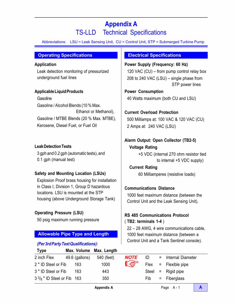
Appendix A Page A - 1 A
Appendix ATS-LLD Technical Specifications
Abbreviations: LSU = Leak Sensing Unit, CU = Control Unit, STP = Submerged Turbine Pump
Operating Specifications
ApplicationLeak detection monitoring of pressurizedunderground fuel lines
Applicable Liquid ProductsGasolineGasoline / Alcohol Blends (10 % Max.
Ethanol or Methanol),Gasoline / MTBE Blends (20 % Max. MTBE),Kerosene, Diesel Fuel, or Fuel Oil
Leak Detection Tests3 gph and 0.2 gph (automatic tests), and0.1 gph (manual test)
Safety and Mounting Location (LSUs)Explosion Proof brass housing for installationin Class I, Division 1, Group D hazardouslocations. LSU is mounted at the STPhousing (above Underground Storage Tank)
Operating Pressure (LSU)50 psig maximum running pressure
Allowable Pipe Type and Length
Electrical Specifications
Power Supply (Frequency: 60 Hz)120 VAC (CU) – from pump control relay box208 to 240 VAC (LSU) – single phase from
STP power linesPower Consumption
40 Watts maximum (both CU and LSU)
Current Overload Protection500 Milliamps at: 100 VAC & 120 VAC (CU)2 Amps at: 240 VAC (LSU)
Alarm Output: Open Collector (TB2-5)Voltage Rating
+5 VDC (internal 270 ohm resistor tiedto internal +5 VDC supply)
Current Rating60 Milliamperes (resistive loads)
Communications Distance1000 feet maximum distance (between theControl Unit and the Leak Sensing Unit).
RS 485 Communications Protocol( TB2: terminals 1-4 )
22 – 28 AWG, 4 wire communications cable,1000 feet maximum distance (between aControl Unit and a Tank Sentinel console).(Per 3rd Party Test Qualifications):
Type Max. Volume Max. Length2 inch Flex 49.6 (gallons) 540 (feet) ID = Internal Diameter2 " ID Steel or Fib 163 1000 Flex = Flexible pipe3 " ID Steel or Fib 163 443 Steel = Rigid pipe3 3/8 " ID Steel or Fib 163 350 Fib = Fiberglass
NOTE+

A Page A - 2 TS-LLD INSTALLATION GUIDE
Appendix ATS-LLD Technical Specifications
Abbreviations: LSU = Leak Sensing Unit, CU = Control Unit, STP = Submerged Turbine Pump
Environmental SpecificationsOperating Temperature
32° to 121° F (0° to 40° C) CU0° to 121° F (-17° to 40° C) LSU
Storage Temperature- 40° to 150° F (- 40° to 65° C)
Operating Humidity (CU)0 to 95% non-condensing
Splash Resistance (CU)Not to be exposed to direct spray, splash,or drips.
Cleaning — See Chapter 5
Mounting Location (CU)Dry indoor location (near the pump relay /motor control box)
WARNING The TS-LLD controlunit must be mounted indoorswhere explosive or flammablevapors are not present, otherwise,an explosion hazard will be createdwhich can result in propertydamage, injury, or death.
Mechanical SpecificationsDisplay — Type:
Alphanumeric LED (Light Emitting Diode)— Size:
1 Line, 2 Digit, 7 Segment (0.54 inches high)
Dimensions (overall in inches)3.35 x 4.35 x 2.25 (H x W x D [ Depth ] ) CU23.5 x 2.4 (H x D [ Diameter ] ) LSU
Safety Approvals and ListingsModel TS-LLD USA
Model TS-LLD/C Canada
See Serial Number labels forthe Model and Serial numbers
ListedLeak DetectionEquipment
Precision Level 2 and Level 3ULC/ORD–C107.12
6L79LISTED
Electronic Line LeakDetector
6L79LISTED
Electronic Line LeakDetector
NOTE+
— v —

User Feedback Form (front side) Page U - 1 U
U User Feedback Form
Your ideas and opinions are important to us ! Please help us improve ourproducts, our service, and our organization... use black ink and print clearly.
Your Name (and Position):
Company Name and Street Address:
(please – no PO Box numbers)
Documentation Provided:Document & Manual Names:
Document & Manual Part Numbers:
Product: Model and Serial Numbers:
Documentation and Manual rating: Installation Date: Today’s Date: Please circle (1 = no / poor, 2 = fair, 3 = okay, 4 = good, 5 = yes / excellent, N = don’t know)
The documentation is easy to use 1 2 3 4 5 NInformation is easy to find 1 2 3 4 5 NThe Table of Contents is useful to find data 1 2 3 4 5 NInformation is well organized 1 2 3 4 5 NInformation is clear and easy to understand 1 2 3 4 5 NInformation is complete and accurate 1 2 3 4 5 NThe illustrations are clear and easy to follow 1 2 3 4 5 NThe number of illustrations are adequate 1 2 3 4 5 N
Comments & Suggestions ? (please be specific)
We’ll listen – we promise !Please complete and returnthis form ...Mail or FAX to
Technical Publications ManagerINTELLIGENT CONTROLS INC74 INDUSTRIAL PARK ROADSACO ME 04072 USA
FAX #: 207-286-8414
#

U Page U - 2 User Feedback Form (back side)
Sale / Supply Orders:
Please circle (1 = no / poor, 2 = fair, 3 = okay, 4 = good, 5 = yes / excellent, N = don’t know)
Your order was processed quickly 1 2 3 4 5 N
You were treated professionally & with respect 1 2 3 4 5 N
You got what you wanted quickly / on time 1 2 3 4 5 N
Sales Suggestions
Technical Service / Support
Please circle (1 = no / poor, 2 = fair, 3 = okay, 4 = good, 5 = yes / excellent, N = don’t know)
Your call was processed quickly 1 2 3 4 5 N
Help and advice was professional & accurate 1 2 3 4 5 N
You were not kept on hold (for a long time) 1 2 3 4 5 N
Service / Support Suggestions
The INCON system or product:
Please circle (1 = no / poor, 2 = fair, 3 = okay, 4 = good, 5 = yes / excellent, N = don’t know)
Was easy to install / service / expand / update 1 2 3 4 5 N
Was easy to program / setup 1 2 3 4 5 N
Operates well and as expected 1 2 3 4 5 N
Product Comments & Suggestions
— v —Thanks for your help & advise !

TS-LLD INSTALLATION GUIDE

PO BOX 638 SACO ME 04072
TS-LLD Installation Guide