inconel alloy 625
TRANSCRIPT
1
INC
ON
EL® a
lloy
625
www.specialmetals.com
INCONEL® nickel-chromium alloy 625 (UNS N06625/W.Nr. 2.4856) is used for its high strength, excellent fabricability (including joining), and out-standing corrosion resistance. Service temperatures range from cryogenic to 1800°F (982°C). Composition is shown in Table 1. Strength of INCONEL alloy 625 is derived from the stiffening effect of molybdenum and niobium on its nickel-chromium matrix; thus precipitation-hardening treatments are not required. This combina-tion of elements also is responsible for superior re-sistance to a wide range of corrosive environments of unusual severity as well as to high-temperature effects such as oxidation and carburization. The properties of INCONEL alloy 625 that make it an excellent choice for sea-water applications are freedom from local attack (pitting and crevice cor-rosion), high corrosion-fatigue strength, high tensile strength, and resistance to chloride-ion stress-corrosion cracking. It is used as wire rope for mooring cables, propeller blades for motor patrol gunboats, submarine auxiliary propulsion motors, submarine quick-disconnect fittings, exhaust ducts for Navy utility boats, sheathing for undersea communication cables, subma-rine transducer controls, and steam-line bellows. Po-tential applications are springs, seals, bellows for sub-merged controls, electrical cable connectors, fasteners, flexure devices, and oceanographic instrument compo-nents. High tensile, creep, and rupture strength; out-standing fatigue and thermal-fatigue strength; oxidation resistance; and excellent weldability and brazeability are the properties of INCONEL alloy 625 that make it interesting to the aerospace field. It is being used in such applications as aircraft ducting systems, engine exhaust systems, thrust-reverser systems, resistance-welded honeycomb structures for housing engine con-trols, fuel and hydraulic line tubing, spray bars, bel-lows, turbine shroud rings, and heat-exchanger tubing in environmental control systems. It is also suitable for combustion system transition liners, turbine seals, com-pressor vanes, and thrust-chamber tubing for rocket
The outstanding and versatile corrosion re-sistance of INCONEL alloy 625 under a wide range of temperatures and pressures is a primary reason for its wide acceptance in the chemical processing field. Be-cause of its ease of fabrication, it is made into a variety of components for plant equipment. Its high strength enables it to be used, for example, in thinner-walled vessels or tubing than possible with other materials, thus improving heat transfer and saving weight. Some applications requiring the combination of strength and corrosion resistance offered by INCONEL alloy 625 are bubble caps, tubing, reaction vessels, distillation columns, heat exchangers, transfer piping, and valves. In the nuclear field, INCONEL alloy 625 may be used for reactor-core and control-rod components in nuclear water reactors. The material can be selected because of its high strength, excellent uniform corro-sion resistance, resistance to stress cracking and excel-lent pitting resistance in 500°-600°F (260-316°C) wa-ter. Alloy 625 is also being considered in advanced reactor concepts because of its high allowable design strength at elevated temperatures, especially between 1200°-1400°F (649-760°C). The properties given in this bulletin, results of extensive testing, are typical of the alloy but should not be used for specification purposes. Applicable specifi-cations appear in the last section of this publication.
Table 1 – Limiting Chemical Composition, %
Nickel…………………………………………….…………58.0 min. Chromium………………………………………..…………20.0-23.0 Iron………………………………………………..………….5.0 max. Molybdenum……………………………….……...…………8.0-10.0 Niobium (plus Tantalum)………………………..………….3.15-4.15 Carbon……………………………………………..……….0.10 max. Manganese………………………………………....……….0.50 max. Silicon……………………………….…………...…………0.50 max. Phosphorus……………………………………….………..0.015 max. Sulfur…………………………………..……….…..……..0.015 max. Aluminum…………………………………………………..0.40 max. Titanium……………………………….……………………0.40 max. Cobalta……………………………………………………….1.0 max.
aIf determined
The data contained in this publication is for informational purposes only and may be revised at any time without prior notice. The data is believed to be accurate and reliable, but Special Metals makes no representation or warranty of any kind (express or implied) and assumes no liability with respect to the accuracy or completeness of the information contained herein. Alt-hough the data is believed to be representative of the product, the actual characteristics or performance of the product may vary from what is shown in this publication. Nothing contained in this publication should be construed as guaranteeing the product for a particular use or application.
Copyright© Special Metals Corporation, 2013 (Aug 13) INCONEL and INCOLOY are trademarks of the Special Metals Corporation group of companies.
2
INC
ON
EL® a
lloy
625
Physical Constants and Thermal Properties
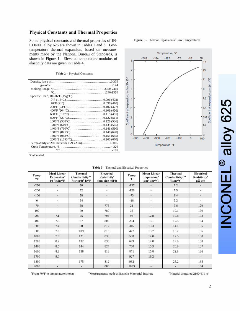
Some physical constants and thermal properties of IN-CONEL alloy 625 are shown in Tables 2 and 3. Low-temperature thermal expansion, based on measure-ments made by the National Bureau of Standards, is shown in Figure 1. Elevated-temperature modulus of elasticity data are given in Table 4.
Table 2 – Physical Constants
Density, lb/cu in………………………………………..………..0.305 gram/cc………………………..………………………….8.44
Melting Range, °F…………………………….......……….2350-2460 °C…………………………………………1290-1350
Specific Heata, Btu/lb°F (J/kg°C) 0°F (-18°C)………………………………0.096 (402) 70°F (21°)………………………………..0.098 (410) 200°F (93°C)……………..………………0.102 (427) 400°F (204°C)……………………………0.109 (456) 600°F (316°C)…………………...……….0.115 (481) 800°F (427°C)…………………...……….0.122 (511) 1000°F (538°C)…………..………………0.128 (536) 1200°F (649°C)…………………………..0.135 (565) 1400°F (760°C)…………………………..0.141 (590) 1600°F (871°C)……………..……………0.148 (620) 1800°F (982°C)…………………….…….0.154 (645) 2000°F (1093°C)…………………..……..0.160 (670)
Permeability at 200 Oersted (15.9 kA/m)…………….………..1.0006 Curie Temperature, °F…………………………...……………..<-320
°C……………………….…………………..-196 aCalculated
Figure 1 – Thermal Expansion at Low Temperatures
Table 3 – Thermal and Electrical Properties
Temp. °F
Meal Linear Expansiona 10-6in/in•°F
Thermal Conductivityb,c Btu•in/ft2-h•°F
Electrical Resistivityc
ohm-circ mil/ft Temp
°C Mean Linear Expansiona µm/ µm•°C
Thermal Conductivity b,c
W/m•°C
Electrical Resistivityc
µΩ-cm -250 - 50 - -157 - 7.2 - -200 - 52 - -129 - 7.5 - -100 - 58 - -73 - 8.4 -
0 - 64 - -18 - 9.2 - 70 - 68 776 21 - 9.8 129 100 - 70 780 38 - 10.1 130 200 7.1 75 794 93 12.8 10.8 132 400 7.3 87 806 204 13.1 12.5 134 600 7.4 98 812 316 13.3 14.1 135 800 7.6 109 818 427 13.7 15.7 136
1000 7.8 121 830 538 14.0 17.5 138 1200 8.2 132 830 649 14.8 19.0 138 1400 8.5 144 824 760 15.3 20.8 137 1600 8.8 158 818 871 15.8 22.8 136 1700 9.0 - - 927 16.2 - - 1800 - 175 812 982 - 25.2 135 2000 - - 806 1093 - - 134
bMeasurements made at Battelle Memorial Institute cMaterial annealed 2100°F/1 hr aFrom 70°F to temperature shown

3
INC
ON
EL® a
lloy
625
Table 4 – Modulus at Elevated Temperaturesa
Temp. °F
Modulus of Elasticity, 103 ksi Poisson’s Ratio Temp.
°C
Modulus of Elasticity, GPa Tension Shear Tension Shear
Annealed Solution- Treated Annealed Solution-
Treated Annealed Solution- Treated Annealed Solution-
Treated Annealed Solution- Treated
70 30.1 29.7 11.8 11.3 0.278 0.312 21 207.5 204.8 81.4 78.0 200 29.6 29.1 11.6 11.1 0.280 0.311 93 204.1 200.6 80.0 76.5 400 28.7 28.1 11.1 10.8 0.286 0.303 204 197.9 193.7 76.5 74.5 600 27.8 27.2 10.8 10.4 0.290 0.300 316 191.7 187.5 74.5 71.7 800 26.9 26.2 10.4 10.0 0.295 0.302 427 185.5 180.6 71.7 68.9 1000 25.9 25.1 9.9 9.6 0.305 0.312 538 178.6 173.1 68.3 66.2 1200 24.7 24.0 9.4 9.2 0.321 0.314 649 170.3 165.5 64.8 63.4 1400 23.3 22.8 8.7 8.8 0.340 0.305 760 160.6 157.2 60.0 60.7 1600 21.4 21.5 8.0 8.3 0.336 0.289 871 147.5 148.2 55.2 57.2
aDetermined dynamically on samples from ¾ -in. hot-rolled rod.
Mechanical Properties
Nominal room-temperature mechanical properties of INCONEL alloy 625 are shown in Table 5. For service at 1200°F and below, hot-finished, cold-finished, and annealed conditions (depending on requirements involved) are recom-mended. For service above 1200°F, either annealed or solution-treated material will give best service. The solution-treated condition is recommended for components that require optimum resistance to creep or rupture. Fine-grained (annealed) material may be advantageous at temperatures up to 1500°F with re-spect to fatigue strength, hardness, and tensile and yield strength. MacGregor’s two-load was used for deter-mination of the true stress-strain curve for alloy 625 at room temperature. The two-load test requires no strain measurement during the test, and only the maximum and fracture loads are recorded. Data for both annealed and solution-treated material are shown in Figure 2.
Figure 2 – True stress-true strain of round.
Table 5 – Nominal Room-Temperature Mechanical Propertiesa
Form And
Condition
Tensile Strength
Yield Strength (0.2% Offset) Elongation Reduction
Of Area Hardness, Brinell
ksi MPa ksi MPa % % ROD, BAR, PLATE
As-Rolled 120-160 827-1103 60-110 414-758 60-30 60-40 175-240 Annealed 120-150 827-1034 60-95 414-655 60-30 60-40 145-220
Solution-Treated 105-130 724-896 42-60 290-414 65-40 90-60 116-194 SHEET and STRIP
Annealed 120-150 827-1034 60-90 414-621 55-30 - 145-240 TUBE and PIPE, COLD-DRAWN
Annealed 120-140 827-965 60-75 414-517 55-30 - - Solution-Treated 100-120 689-827 40-60 276-414 60-40 - -
aValues shown are composites for various product sizes up to 4 in. They are not suitable for specification purposes. For properties of larger-sized products, consult Special Metals Corporation.

4
INC
ON
EL® a
lloy
625
Tensile Properties and Hardness
Typical tensile properties of annealed and solution-treated material from room to elevated temperature are shown in Figures 3, 4, and 5. The approximate relationship between the hardness and tensile and yield strength of strip is shown in Figure 6. Increased tensile properties for service at moderate temperature can be achieved by cold work. See the section, “Working Instructions” for some specific data. Upon exposure to intermediate tempera-tures, some hardening takes place in alloy 625. To demonstrate this reaction, samples of annealed rod were exposed to 1200°, 1400°, and 1600°F for 2000 hours. The effect of exposure on properties both at room temperature and at exposure temperature is shown in Table 6. Measurements were made to de-termine dimensional stability; the samples exposed at 1200° to 1400°F for 2000 hours contracted about 0.048%.
Figure 3 – High-temperature tensile properties of annealed bar.
Table 6 – Effect of Intermediate-Temperature Exposure (2000 hrs) on Properties of Hot-Rolled Annealed Bar
Exposure Temperature,
°F (°C)
Properties at Room Temperature Properties at Exposure Temperature
Tensile Strength Yield Strength (0.2% offset) Elongation,
% Tensile Strength Yield Strength
(0.2% offset) Elongation, %
ksi MPa ksi MPa ksi MPa ksi MPa No Exposure 140.0 965.3 69.5 479.2 54 - - - - - 1200 (649) 176.0 1213.5 126.5 872.2 30 146.5 1010.1 106.5 734.3 54 1400 (760) 163.0 1123.8 107.0 737.7 26 84.8 584.7 79.0 544.7 62 1600 (871) 144.0 992.8 76.7 528.8 34 41.2 284.1 40.0 275.8 80
aValues shown are composites for various product sizes up to 4 in. They are not suitable for specification purposes. For properties of larger-sized products, consult Special Metals Corporation.

5
INC
ON
EL® a
lloy
625
Figure 4 – High-temperature tensile properties of cold-rolled annealed sheet.
Figure 5 – High-temperature tensile properties of hot-rolled solution-treated rod.
Figure 6 – Approximate relationships between hardness and tensile properties of strip.

6
INC
ON
EL® a
lloy
625 Figure 7 – Fatigue strength at room temperature of hot-rolled
round (5/8-in. diameter).
Figure 8 – Rotating-beam fatigue strength of hot-rolled solution-treated bar (0.625-in. diameter) at elevated temperature. Average grain size, 0.004 in.
Fatigue Strength
Room-temperature fatigue strength of hot-rolled round in the as-rolled and annealed conditions is shown in Fig-ure 7. Elevated-temperature fatigue strengths of solution-treated and annealed bar can be compared in Figures 8 and 9. The endurance limit (108 cycles) at room temperature of cold-rolled annealed sheet tested in completely reversed bending was found to be 90,000 psi for smooth bar and 35,000 psi (notched specimen Kt+3.3).
Figure 9 – Rotating-beam fatigue strength of hot-rolled annealed bar (0.625-in. diameter) at elevated temperature. Average grain size, 0.0006 in.; room-temperature hardness, 24.5 Rc.

7
INC
ON
EL® a
lloy
625
Ductility and Toughness
INCONEL alloy 625 retains its excellent ductility and toughness at low temperature. Impact and tensile data to -320°F are shown in Table 7 and Figure 10.
Table 7 – Low-Temperature Impact Strengtha of Hot-Rolled, As-Rolled Plate (1/2-in. thickness)
Test Temperature, Orientation Impact Strength,
°F °C ft•lb J 85 29 Longitudinal 48, 49, 50 65, 66, 68 Transverse 46, 49, 51.5 62, 66, 70
-110 -79 Longitudinal 39, 44, 49 53, 57, 60 Transverse 39, 42, 44 53, 57, 60
-320 -196 Longitudinal 35, 35, 35.5 47, 47, 48 Transverse 31, 32, 36 42, 43, 49
aCharpy keyhole specimens in triplicate.
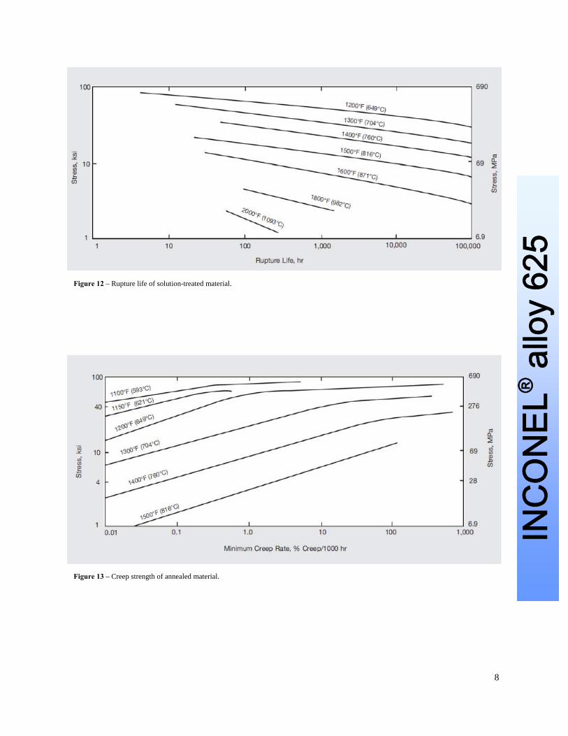
Creep and Rupture Strength
Typical creep and rupture strength of solution-treated material is given in Figures 11 and 12. For comparison purposes, creep and rupture properties of annealed material are shown in Figures 13 and 14. Annealed material, when selected for some other consideration, will exhibit adequate creep-rupture properties for many applications, although the values are not as high as those shown for solution-treated material.
Figure 10 – Tensile properties of cold-rolled (20% reduction), as-rolled sheet (0.024 gage) from low to elevated temperatures.
Figure 11 – Creep strength of solution-treated material.
8
INC
ON
EL® a
lloy
625
Figure 12 – Rupture life of solution-treated material.
Figure 13 – Creep strength of annealed material.

9
INC
ON
EL® a
lloy
625
Figure 14 – Rupture life of annealed material.
ASME Boiler and Pressure Vessel Code Microstructure
INCONEL alloy 625 is an approved material of con-struction under the Boiler and Pressure Vessel Code of the American Society of Mechanical Engineers (ASME). Allowable design stresses for Grade 1 ma-terial for Section VIII, Division 1 construction up to 1200°F, for Section III, Class 2 and 3 construction up to 800 °F, and for Grade 2 material for Section VIII, Division 1 construction up to 1600°F are reported in Table 1B of ASME Section II, Part D. Design stress intensity values for Section III, Class 1 construction for Grade 1 material are found in Table 2B of ASME Section II, Part D. Allowable stresses and rules for Section 1 construction with Grade 1 material up to 1100°F are found in ASME Code Case 1935.
INCONEL alloy 625 is a solid-solution matrix-stiffened face-centered-cubic alloy. The alloy may contain carbides, which are inherent in this type of alloy. Carbides that can be found are MC and M6C (rich in nickel, niobium, molybdenum, and carbon). In addition M23C6, a chromium-rich carbide, appears in solution-treated material exposed at lower temper-atures. The hardening effect that takes place in the material on exposure in the range centered around 1200°F (See Mechanical Properties section) is due to sluggish precipitation of a nickel-niobium-rich phase, gamma prime. This phase gradually transforms to orthorhombic Ni3Nb when the alloy is heated for long times in the intermediate temperature range. Extensive investigation of the stability of alloy 625 following exposure for extended periods in the 1000° to 1800°F temperature range has shown complete absence of embrittling intermetallic phases such as sigma.

10
INC
ON
EL® a
lloy
625
Corrosion Resistance
Aqueous Corrosion
The high alloy content of INCONEL alloy 625 enables it to withstand a wide variety of severe corrosive envi-ronments. In mild environments such as the atmosphere, fresh and sea water, neutral salts, and alkaline media there is almost no attack. In more severe corrosive environments the combination of nickel and chromium pro-vides resistance to oxidizing chemicals, whereas the high nickel and molybdenum contents supply resistance to nonoxidizing environments. The high molybdenum content also makes this alloy very resistant to pitting and crevice corrosion, and niobium acts to stabilize the alloy against sensitization during welding, thereby preventing subsequent intergranular cracking. Also, the high nickel content provides freedom from chloride ion stress-corrosion cracking. This combination of characteristics makes INCONEL alloy 625 useful over a broad spectrum of corro-sive conditions. For instance, it has been recommended as a material of construction for a storage tank to handle chemical wastes, including hydrochloric and nitric acids – chemicals which represent directly opposite types of corrosion problems. Materials which resist either one of these acids are normally severely attacked by the other. More general information may be found in the publication ‘High Performance Alloys for Resistance to Aqueous Corrosion’ on our website, www.specialmetals.com.
High-Temperature Oxidation
INCONEL alloy 625 has good resistance to oxidation and scaling at high temperature. Its performance in an extremely sever test is shown in comparison with that of other materials in Figure 15. In this test, peri-odic weight-loss determinations indicate the ability of the alloy to retain a protective oxide coating under drastic cyclic conditions. 1800°F is a temperature at which scaling resistance becomes a significant factor in service.
Figure 15 – Scaling resistance at 1800°F (Hastelloy® is a trademark of Haynes International)
Working Instructions
Hot- or cold-formed parts are usually annealed at 1700°-1900°F for times commensurate with thickness; higher temperatures may be used to soften material for additional cold work. INCONEL alloy 625 is solution-treated at 2000°-2200°F. These temperatures are metal temperatures based on batch operations and may not apply to con-tinuous annealing, which normally consists of short exposure in the hot zone of a furnace set at higher tempera-tures. The rate of cooling after heating has no significant effect on INCONEL alloy 625. Tables 8 and 9 can be used as a guide for determining the preferred temperature for reducing the stress level of the alloy. Heating cold-drawn material at 1100° to 1400°F reduces residual stress. Stress relief is virtu-ally complete when the material is heated to 1600°F. The effect of annealing on hardness of sheet given varying amounts of cold reduction is shown in Fig-ure 16.
Heating

11
INC
ON
EL® a
lloy
625
Table 8 – Effect of Annealing (1 hour) on Room-Temperature Properties of Hot-Rolled Rod
Annealing Temper-
ature, °F
Tensile Strength,
ksi
Yield Strength
(0.2% Offset),
ksi
Elonga-tion, %
Reduction Of Area,
% Hardness,
Rb
As-Rolled 147.5 92.0 46.0 55.3 98 1400 145.5 90.8 43.0 49.5 101 1500 143.5 85.0 42.0 45.7 101 1600 145.5 87.2 39.0 41.5 101 1700 147.0 86.0 40.0 48.0 103 1800 143.5 83.6 44.0 48.0 101 1850 142.5 78.6 46.0 53.0 99 1900 142.5 66.3 49.0 51.5 95 2000 124.0 52.5 64.0 62.5 93 2100 116.0 50.0 62.0 61.0 89 2200 116.5 48.0 72.0 61.3 88
Annealing Temper-
ature, °C
Tensile Strength,
MPa
Yield Strength
(0.2% Offset),
MPa
Elonga-tion, %
Reduction Of Area,
% Hardness,
Rb
As-Rolled 1017.0 634.3 46.0 55.3 98 760 1003.2 626.0 43.0 49.5 101 816 989.4 586.1 42.0 45.7 101 871 1003.2 601.2 39.0 41.5 101 927 1013.5 593.0 40.0 48.0 103 982 989.4 576.4 44.0 48.0 101 1010 982.5 542.0 46.0 53.0 99 1038 982.5 457.1 49.0 51.5 95 1093 855.0 362.0 64.0 62.5 93 1149 799.8 344.7 62.0 61.0 89 1204 803.2 331.0 72.0 61.3 88
Figure 8 – Effect of annealing temperature on the hardness Of sheet (30 min at temperature).
Table 9 – Effect of Annealing (1 Hour) on Room-Temperature Properties of Cold-Drawn Rod
Annealing Temperature,
Tensile Strength,
Yield Strength (0.2% Offset), Elongation
%
Reduction Of Area,
% Hardness,
Rb
Impact Strength
(Charpy V) Grain Size,
°F °C ksi MPa ksi MPa ft•lb J in. mm As-
Drawn As-
Drawn 163.0 1123.8 145.5 1003.2 21.0 50.5 106 64.5 87.5 0.003 .076 1100 593 160.5 1106.6 134.3 926.0 28.0 48.3 106 75.0 101.7 0.0035 .089 1200 649 159.5 1099.7 133.5 920.5 28.5 47.2 106 71.5 97.0 0.0045 .114 1300 704 164.0 1130.7 135.0 930.8 26.0 38.8 106 57.0 77.3 0.005 .127 1400 760 162.5 1120.4 135.5 934.2 27.0 39.0 106 53.0 71.9 0.005 .127 1500 816 152.0 1048.0 120.0 827.4 29.0 41.5 105 55.0 74.6 0.0035 .089 1600 871 146.5 1010.1 102.5 706.7 35.0 45.2 103 62.0 84.1 70% 0.005 .127
30% 0.009 .229 1700 927 133.5 920.5 62.3 429.5 48.5 44.0 97 82.5 111.9 0.0008 .203 1800 982 127.5 879.1 62.3 429.5 52.0 55.3 95 84.5 114.6 0.0009 .229 1900 1038 130.5 899.8 60.8 419.2 53.0 55.7 95 91.0 123.4 0.0008 .203 2000 1093 126.5 872.2 56.5 389.6 57.0 61.0 93 115.5 156.6 0.0019 .048 2100 1149 118.0 813.6 48.3 333.0 63.0 60.4 89 138.0 187.1 0.0032 .081 2200 1204 113.0 779.1 44.6 307.5 62.3 58.4 86 141.0 191.2 0.006 .152

12
INC
ON
EL® a
lloy
625
Pickling
When heated, INCONEL alloy 625, like other nickel-chromium and nickel-chromium-iron alloys, forms a tight-ly adherent oxide or scale unless it has been bright-annealed in very dry hydrogen or in a vacuum. To remove the oxide which results from heating, treatment in a fused-salt bath prior to pickling is usually recommended. Comments on applicable salt baths and pickling solutions may be found in the publication ‘Fabricating’ on the Special Metals website, www.specialmetals.com.
Hot and cold forming
Because INCONEL alloy 625 was especially developed to retain high strength at elevated temperature, it resists deformation at hot-working temperatures. It is readily fabricated by hot forming, however, provided adequately powerful equipment is used. When INCONEL alloy 625 is hot-formed, it should be heated in a furnace whose temperature is held at (but not above) 2150°F. The work should be brought up to as close to 2150°F as conditions permit. Heavy forg-ing can be carried out from 2150°F down to 1850°F. Lighter reductions can be taken down to 1700°F. To guard against duplex grain structure, the work should be given uniform reductions. Final minimum reductions of 15 to 20% for open-die work are recommended. INCONEL alloy 625 can be cold-formed by standard processes. The force required to shear the alloy in the annealed condition is shown in Figure 17. More indications of its resistance to deformation can be derived from the true stress-true strain curves (see the “Mechanical Properties” section of this bulletin) and the effect of cold work on hardness (Figure 18). Increased tensile properties can be achieved by cold work for moderate-temperature applications. Ten-sile strengths of more than 300,000 psi accompanied by good ductility have been developed in 0.010-0.020-in.-diameter wire after 75-90% cold reduction (See Table 10). Effects of cold work on plate are shown in Table 11. Further information on hot- and cold-forming INCONEL alloy 625 can be found in the publication ‘Fabricating’ on our website, www.specialmetals.com.
Table 10 – Room-Temperature Tensile Properties of As-Drawn Wirea
Wire Diameter,
Cold Reduc-tion,
%
Tensile Strength
Yield Strength (0.2% offset)b,
Elonga-tion In
10 Inches,
% In. Mm ksi MPa ksi MPa
0.0397c 1.008c 0 138 952 61.5 424 52.3 0.036 0.914 19 174.5 1203 153.3 1057 17.5
0.0318d 0.808d 37 220 1517 205 1413 2.0 0.0285d 0.724d 49 246 1696 218 1503 2.0 0.0253d 0.643d 60 269 1855 253 1744 2.4 0.0226d 0.574d 68 283 1951 242 1669 2.2 0.020d 0.508d 75 293 2020 251 1731 2.0 0.0179 0.455 80 295.3 2036 220 1517 3.8 0.0159 0.404 84 303 2089 250 1727 3.4 0.0142 0.361 87 306 2110 252.8 1743 3.0 0.0126 0.320 90 316 2181 269 1855 2.6 0.0111 0.282 92 316 2179 264 1820 2.3 0.0099 0.251 94 322.3 2222 274.5 1893 3.0
aAverage of 2 tests unless otherwise shown. bCrosshead speed, 0.1 in./min. cStrand-annealed at 2150°F, 29 ft/min, in 10-ft furnace with 6-7 ft hot zone dOne test.
Figure 17 – Loads required for shearing annealed material (hydraulic shear, 21/64 in./ft knife rake).

13
INC
ON
EL® a
lloy
625
Table 11 – Effect of Cold Work on Mechanical Properties of Strips Cut From Hot-Rolled Plate (0.372-in.), Solution-Treated 2150°F/1 hr and Cold Worked
Cold Reduction,
%
Tensile Strength
Yield Strength (0.2% offset)b Elongation
% Reduction Of Area,
%
Hardness
ksi MPa ksi MPa Rockwell C Vickers 0 115.5 796.3 49.5 341.3 67.0 60.4 88 Rb 179 5 121.0 834.3 77.5 534.3 58.0 58.1 94 Rb 209 10 130.0 896.3 102.5 706.7 47.5 54.6 25 257 15 137.0 944.6 112.5 775.7 39.0 51.9 32 309 20 143.0 986.0 125.0 861.8 31.5 50.0 34 326 30 165.0 1137.6 152.0 1048.0 17.0 49.3 36 344 40 179.5 1237.6 167.0 1151.4 12.5 41.9 39 372 50 189.5 1306.6 177.0 1220.4 8.5 38.0 40 382 60 205.0 1413.4 180.5 1244.5 6.5 32.7 44 427 70 219.0 1510.0 201.0 1385.8 5.0 25.4 45 440
Figure 18 – Effect of cold work on hardness.
14
INC
ON
EL® a
lloy
625
Machining
Guidelines for machining INCONEL alloy 625 are given in the publication ‘Machining’ on the Special Metals website, www.specialmetals.com.
Table 12 – Recommended Conditions for Turning with Single-Point Tools
High Speed Steel Coated Carbide Surface Speed Feed Surface Speed Feed
fpm m/min lpr Mm/rev fpm m/min lpr m/rev 13-35 4.0-10.7 0.005-0.020 0.13-0.51 45-110 14-34 0.005-0.020 0.13-0.51
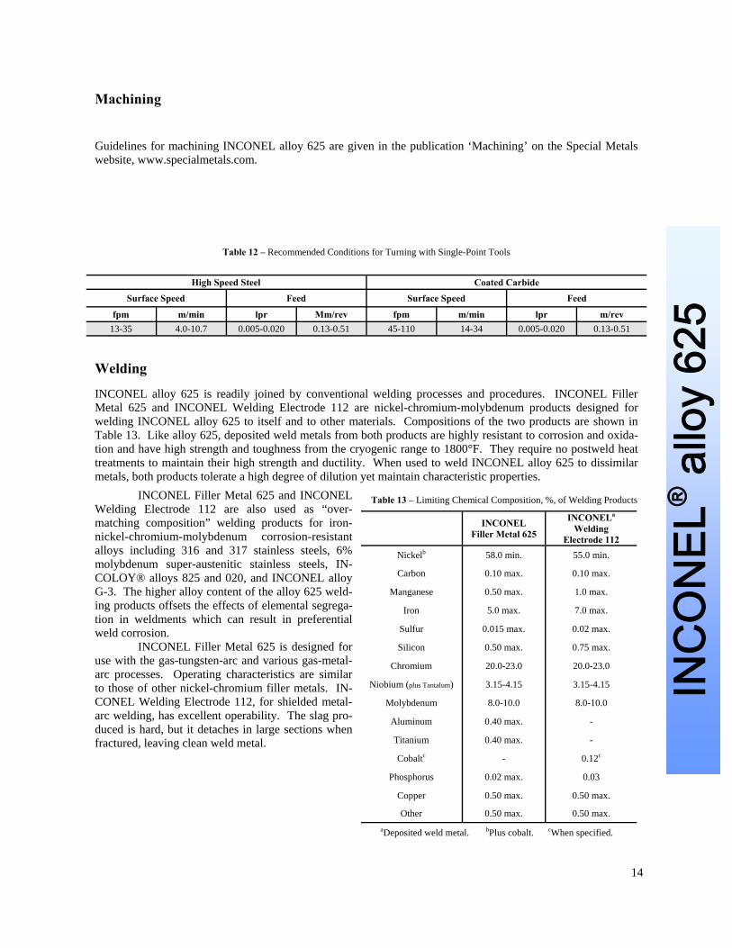
Welding
INCONEL alloy 625 is readily joined by conventional welding processes and procedures. INCONEL Filler Metal 625 and INCONEL Welding Electrode 112 are nickel-chromium-molybdenum products designed for welding INCONEL alloy 625 to itself and to other materials. Compositions of the two products are shown in Table 13. Like alloy 625, deposited weld metals from both products are highly resistant to corrosion and oxida-tion and have high strength and toughness from the cryogenic range to 1800°F. They require no postweld heat treatments to maintain their high strength and ductility. When used to weld INCONEL alloy 625 to dissimilar metals, both products tolerate a high degree of dilution yet maintain characteristic properties.
INCONEL Filler Metal 625 and INCONEL Welding Electrode 112 are also used as “over-matching composition” welding products for iron-nickel-chromium-molybdenum corrosion-resistant alloys including 316 and 317 stainless steels, 6% molybdenum super-austenitic stainless steels, IN-COLOY® alloys 825 and 020, and INCONEL alloy G-3. The higher alloy content of the alloy 625 weld-ing products offsets the effects of elemental segrega-tion in weldments which can result in preferential weld corrosion. INCONEL Filler Metal 625 is designed for use with the gas-tungsten-arc and various gas-metal-arc processes. Operating characteristics are similar to those of other nickel-chromium filler metals. IN-CONEL Welding Electrode 112, for shielded metal-arc welding, has excellent operability. The slag pro-duced is hard, but it detaches in large sections when fractured, leaving clean weld metal.
Table 13 – Limiting Chemical Composition, %, of Welding Products
INCONEL Filler Metal 625
INCONELa Welding
Electrode 112 Nickelb 58.0 min. 55.0 min.
Carbon 0.10 max. 0.10 max.
Manganese 0.50 max. 1.0 max.
Iron 5.0 max. 7.0 max.
Sulfur 0.015 max. 0.02 max.
Silicon 0.50 max. 0.75 max.
Chromium 20.0-23.0 20.0-23.0
Niobium (plus Tantalum) 3.15-4.15 3.15-4.15
Molybdenum 8.0-10.0 8.0-10.0
Aluminum 0.40 max. -
Titanium 0.40 max. -
Cobaltc - 0.12c
Phosphorus 0.02 max. 0.03
Copper 0.50 max. 0.50 max.
Other 0.50 max. 0.50 max. aDeposited weld metal. bPlus cobalt. cWhen specified.

15
INC
ON
EL® a
lloy
625
All-Weld-Metal Properties
High-temperature properties of weld metals are shown in Figures 19, 20, and 21. These welds were made by the gas-tungsten-arc process and the shield-ed-metal-arc process. Low-temperature toughness of weld metals is shown by the impact-strength data in Table 14. Room-temperature fatigue strength (106 cycles; rotating-beam tests at 10,000 rpm) of pol-ished all-weld-metal specimens was found to be 68,000 psi (Filler Metal 625) and 58,000 psi (Electrode 112). The results of stress-rupture tests performed on all-weld-metal specimens of Electrode 112 are reported in Figure 22.
Table 14 – Low-Temperature Impact Strength of INCONEL Welding Products All-Weld Metal
Welding Material
Notch Orientation To Welding
Direction
Charpy V-Notch Impact Strength, ft-lb (J)
-320°F (-196°C)
-110°F (-79°C)
Room Tempera-
ture Filler Metal
625a Perpendicular 57.0 (77.3) 60.0 (81.5) 68.5 (92.9) Electrode
112 Perpendicular 34.8 (47.2) 42.5 (57.6) 46.5 (63.1) Parallel 32.8 (44.5) 41.5 (56.3) 45.0 (61.0)
aGas-tungsten-arc welding process.
Figure 20 – High-temperature tensile properties of INCONEL alloy 625 all-weld metal (1/2-in. solution-treated plate; gas-tungsten-arc process with INCONEL Filler Metal 625).
Figure 21 – High-temperature tensile properties of deposited weld metal from weld made in alloy 625 with Welding Electrode 112.
Figure 19 – High-temperature tensile properties of transverse specimens of INCONEL alloy 625 welds (1/2-in. solution-treated plate; gas-tungsten-arc process with INCONEL Filler Metal 625).

16
INC
ON
EL® a
lloy
625
Figure 22 – Rupture strength of INCONEL Welding Electrode 112 all-weld metal.
Figure 23 – 100-hr rupture strength of transverse specimens from joints n alloy 625 made by gas-tungsten-arc process using Filler Metal 625.

17
INC
ON
EL® a
lloy
625
Transverse Properties
Properties of INCONEL alloy 625 welds made with the recommended welding products are shown in Figures 19 and 21.
As another example of weld quality, the gas-tungsten-arc process with 1/8-in. Filler Metal 625 was used to join 1/2-in. annealed plate. Transverse bends with a radius equal to two thicknesses (2T) had no fissuring or cracking. Rupture strength of alloy 625 welds made by the gas-tungsten-arc process and Filler Metal 625 is shown in Figure 23. Both INCONEL Filler Metal 625 and INCONEL Welding Electrode 112 have been used to join alloy 625 to a variety of dissimilar metals. The results of tests made on welds of alloy 625 joined to a nickel-iron-chromium-molybdenum alloy (Hastelloy® alloy X), a precipitation-hardenable nickel-chromium alloy (INCONEL alloy 718), a cast chromium-nickel-iron-tungsten alloy (MO-RE 1) and Types 304 and 410 stainless steel are shown in Table 15. All the joints passed dye-penetrant and radiographic inspection and guided-bend tests. Barker, Cox, and Margolin report the results of tests on joints between alloy 625 sheet and other dissimilar metals.
Table 15 – Strength of Dissimilar Weldsa
INCONEL alloy 625 Joined to
Gas-Metal-Arc (Spray Transfer)
With Filler Metal 265 Gas-Tungsten-Arc
With Filler Metal 625 Shielded-Metal-Arc
With Welding Electrode 112
Tensile Strength, Ksi (MPa)
Fracture Location
Tensile Strength, Ksi (MPa)
Fracture Location
Tensile Strength, Ksi (MPa)
Fracture Location
Hastelloy alloy X 121.2 (835.6) Alloy X 119.7 (825.3) Alloy X 118.5 (817.0) Alloy X
INCONEL alloy 718 120.7 (832.2) Alloy 718 107.5 (741.2) Alloy 718 110.25 (760.1) Alloy 718
Type 304 Stainless Steel 88.5 (610.2) Type 304 92.0 (634.3) Type 304 91.25 (629.1) Type 304
Type 410 Stainless Steel 65.6 (452.3) Type 410 67.6 (466.1) Type 410 61.6 (424.7) Type 410 MO-RE® 1 - - 97.3 (670.9) MO-RE 1 94.7 (653.0) MO-RE 1
aTransverse specimens. Joints were 3/8 in. thick except for those with MO-RE 1, which were ½ in. bThese joints were preheated to 300°F. Hastelloy is a trademark of Haynes International, and MO-RE is a trademark of Blaw-Knox Corporation
18
INC
ON
EL® a
lloy
625
Available Products and Specifications
INCONEL alloy is designated as UNS N06625, Werkstoff Number 2.4856 and ISO NW6625 and is listed in NACE MR-01-75. It is available in all standard mill forms including rod, bar, wire, and wire rod, plate, sheet, strip, shapes, tubular products, and forging stock. Full information on available products may be obtained from the offices listed on the back cover. Rod, Bar, Wire and Forging Stock - ASTM B 446/ASME SB 446 (Rod & Bar), ASTM B 564/ASME SB 564 (Forgings), SAE/AMS 5666 (Bar, Forgings, & Rings), SAE/AMS 5837 (Wire), ISO 9723 (Rod & Bar), ISO 9724 (Wire), ISO 9725 (Forgings), VdTÜV 499 (Rod & Bar), BS 3076NA21 (Rod & Bar), EN 10095 (Rod, Bar, & Sections), DIN 17752 (Rod & Bar), ASME Code Case 1935 (Rod, Bar, & Forgings), DIN 17754 (forgings), DIN 17753 (Wire). Plate, Sheet and Strip - ASTM B 443/ASTM SB 443 (Plate, Sheet & Strip), SAE/AMS 5599 & 5869 & MAM 5599 (Plate, Sheet & Strip), ISO 6208 (Plate, Sheet & Strip), VdTÜV 499 (Plate, Sheet & Strip), BS 3072NA21 (Plate & Sheet), EN 10095 (Plate, Sheet & Strip), DIN 17750 (Plate, Sheet & Strip), ASME Code Case 1935. Pipe & Tube - ASTM B 444/B 829 & ASME SB 444/SB 829 (Seamless Pipe & Tube), ASTM B704/B 751 & ASME SB 704/SB 751 (Welded Tube), ASTM B705/B 775 & ASME SB 705/SB 775 (Welded Pipe), ISO 6207 (Tube), SAE/AMS 5581 (Seamless & Welded Tube), VdTÜV 499 (Tube), BS 3074NA21 (Seamless Pipe & Tube), DIN 17751 (Tube), ASME Code Case 1935. Other Product Forms - ASTM B 366/ASME SB 366 (Fittings), ISO 4955A (Heat Resisting Steels & Alloys), DIN 17744 (Chemical composition of all product forms).