incra cleansweep leansweep downdraft dust … · if you plan to also use your router table router...
TRANSCRIPT
Manufactured by Taylor Design Group, Inc. P.O. Box 810262 Dallas, TX 75381 ©2013 by Taylor Design Group, Inc. All rights reserved.
w w w . i n c r a . c o m
Owner’s Manual
INCRA CleanSweepDowndraft Dust Collection CabinetCLEANSWEEP
Downdraft Dust Collection CabinetDowndraft Dust Collection Cabinet
° Before using the INCRA CleanSweep, read and follow all instructions and safety information in this manual.
° Before using the INCRA CleanSweep in conjunction with any other tool, first read and follow all instructions and safety information in that tool’s owner’s manual.
° When making any cut, always use a push stick, rubber soled push block, or other safety device to keep your hands safely away from the cutting tool.
° Always wear safety glasses, hearing protection and follow all normal shop safety practices.
° AVOID OVERHEATING YOUR ROUTER BY PROVIDING ADEQUATE VENTILATION. Make sure your dust collection system is turned on and working properly whenever your router is operated inside the CleanSweep Cabinet. If you operate your router inside the CleanSweep Cabinet with your dust collector turned off or not working properly, you MUST first follow the 3 steps below. 1) Open the CleanSweep Door. 2) Open the Blast Gate Slide. 3) Remove the dust collection hose.
Important safety instructions for using the INCRA CleanSweepSAFETY:
INCRA CLEANSWEEP DOWNDRAFT DUST COLLECTION CABINET OWNER’S MANUALINCRA CLEANSWEEP DOWNDRAFT DUST COLLECTION CABINET OWNER’S MANUAL
Manufactured by Taylor Design Group, Inc. P.O. Box 810262 Dallas, TX 75381 W W W. I N C R A . C O M ©2013 by Taylor Design Group, Inc. All rights reserved.
Page 2 Page 3
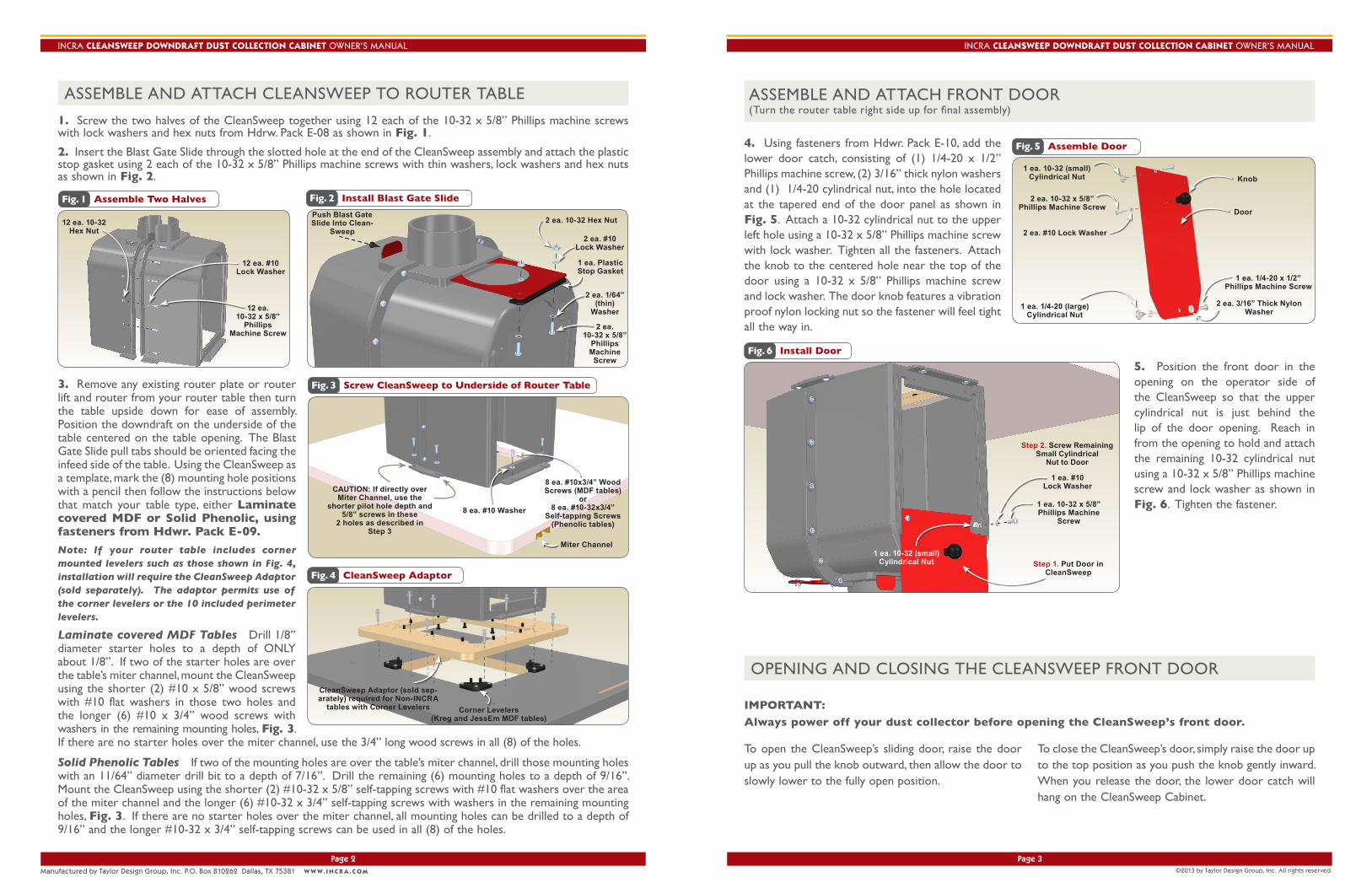
ASSEMBLE AND ATTACH FRONT DOOR (Turn the router table right side up for final assembly)
3. Remove any existing router plate or router lift and router from your router table then turn the table upside down for ease of assembly. Position the downdraft on the underside of the table centered on the table opening. The Blast Gate Slide pull tabs should be oriented facing the infeed side of the table. Using the CleanSweep as a template, mark the (8) mounting hole positions with a pencil then follow the instructions below that match your table type, either Laminate covered MDF or Solid Phenolic, using fasteners from Hdwr. Pack E-09.
Note: If your router table includes corner mounted levelers such as those shown in Fig. 4, installation will require the CleanSweep Adaptor (sold separately). The adaptor permits use of the corner levelers or the 10 included perimeter levelers.
Laminate covered MDF Tables Drill 1/8” diameter starter holes to a depth of ONLY about 1/8”. If two of the starter holes are over the table’s miter channel, mount the CleanSweep using the shorter (2) #10 x 5/8” wood screws with #10 flat washers in those two holes and the longer (6) #10 x 3/4” wood screws with washers in the remaining mounting holes, Fig. 3. If there are no starter holes over the miter channel, use the 3/4” long wood screws in all (8) of the holes.
Solid Phenolic Tables If two of the mounting holes are over the table’s miter channel, drill those mounting holes with an 11/64” diameter drill bit to a depth of 7/16”. Drill the remaining (6) mounting holes to a depth of 9/16”. Mount the CleanSweep using the shorter (2) #10-32 x 5/8” self-tapping screws with #10 flat washers over the area of the miter channel and the longer (6) #10-32 x 3/4” self-tapping screws with washers in the remaining mounting holes, Fig. 3. If there are no starter holes over the miter channel, all mounting holes can be drilled to a depth of 9/16” and the longer #10-32 x 3/4” self-tapping screws can be used in all (8) of the holes.
ASSEMBLE AND ATTACH CLEANSWEEP TO ROUTER TABLE
Fig. 1 Assemble Two Halves
12 ea. 10-32Hex Nut
1. Screw the two halves of the CleanSweep together using 12 each of the 10-32 x 5/8” Phillips machine screws with lock washers and hex nuts from Hdrw. Pack E-08 as shown in Fig. 1.
12 ea. #10Lock Washer
12 ea.10-32 x 5/8”
PhillipsMachine Screw
Fig. 2 Install Blast Gate Slide
Push Blast Gate Slide Into Clean-
Sweep
2 ea. 10-32 Hex Nut
2 ea. #10Lock Washer
1 ea. Plastic Stop Gasket
2 ea. 1/64”(thin)
Washer
2 ea.10-32 x 5/8”
PhillipsMachineScrew
2. Insert the Blast Gate Slide through the slotted hole at the end of the CleanSweep assembly and attach the plastic stop gasket using 2 each of the 10-32 x 5/8” Phillips machine screws with thin washers, lock washers and hex nuts as shown in Fig. 2.
Fig. 5 Assemble Door
1 ea. 10-32 (small)Cylindrical Nut
4. Using fasteners from Hdwr. Pack E-10, add the lower door catch, consisting of (1) 1/4-20 x 1/2” Phillips machine screw, (2) 3/16” thick nylon washers and (1) 1/4-20 cylindrical nut, into the hole located at the tapered end of the door panel as shown in Fig. 5. Attach a 10-32 cylindrical nut to the upper left hole using a 10-32 x 5/8” Phillips machine screw with lock washer. Tighten all the fasteners. Attach the knob to the centered hole near the top of the door using a 10-32 x 5/8” Phillips machine screw and lock washer. The door knob features a vibration proof nylon locking nut so the fastener will feel tight all the way in.
Knob
1 ea. 1/4-20 x 1/2”Phillips Machine Screw
Fig. 6 Install Door
Step 2. Screw RemainingSmall Cylindrical
Nut to Door
1 ea. 10-32 (small) Cylindrical Nut
1 ea. #10Lock Washer
Step 1. Put Door in CleanSweep
1 ea. 10-32 x 5/8”Phillips Machine
Screw
5. Position the front door in the opening on the operator side of the CleanSweep so that the upper cylindrical nut is just behind the lip of the door opening. Reach in from the opening to hold and attach the remaining 10-32 cylindrical nut using a 10-32 x 5/8” Phillips machine screw and lock washer as shown in Fig. 6. Tighten the fastener.
2 ea. 10-32 x 5/8”Phillips Machine Screw
2 ea. #10 Lock Washer
1 ea. 1/4-20 (large)Cylindrical Nut
Door
2 ea. 3/16” Thick Nylon Washer
OPENING AND CLOSING THE CLEANSWEEP FRONT DOOR
To open the CleanSweep’s sliding door, raise the door up as you pull the knob outward, then allow the door to slowly lower to the fully open position.
To close the CleanSweep’s door, simply raise the door up to the top position as you push the knob gently inward. When you release the door, the lower door catch will hang on the CleanSweep Cabinet.
IMPORTANT:
Always power off your dust collector before opening the CleanSweep’s front door.
Fig. 4 CleanSweep Adaptor
CleanSweep Adaptor (sold sep-arately) required for Non-INCRA
tables with Corner Levelers Corner Levelers(Kreg and JessEm MDF tables)
Fig. 3 Screw CleanSweep to Underside of Router Table
8 ea. #10x3/4” Wood Screws (MDF tables)
or8 ea. #10-32x3/4”
Self-tapping Screws(Phenolic tables)
8 ea. #10 Washer
Miter Channel
CAUTION: If directly over Miter Channel, use the
shorter pilot hole depth and 5/8” screws in these
2 holes as described in Step 3
MADE IN THE
USAManufactured by:Taylor Design Group, Inc. P.O. Box 810262 Dallas, TX 75381www.incra.com P: 972-242-9975/F: 972-242-9985
INCRA Tools are protected by one or more of the following US patents: #4,793,604, #4,930,221, #5,195,730, #5,275,074, #5,423,360, #5,716,045, #6,237,457, #6,557,601, #6,672,190. Rev. 5/13
INCRA is a Registered Trademark of Taylor Design Group, Inc. ©2013 Taylor Design Group, Inc.
Page 4
INCRA CLEANSWEEP DOWNDRAFT DUST COLLECTION CABINET OWNER’S MANUAL
Fig. 7 Install Back Plate
4ea. 10-32Hex Nut
(Captured inhex feature)
Back Plate
4ea. 10-32 x 5/8”Phillips Machine
Screw
Router is Sitting on Table Top
Router Cord
4 ea. #10Lock Washer
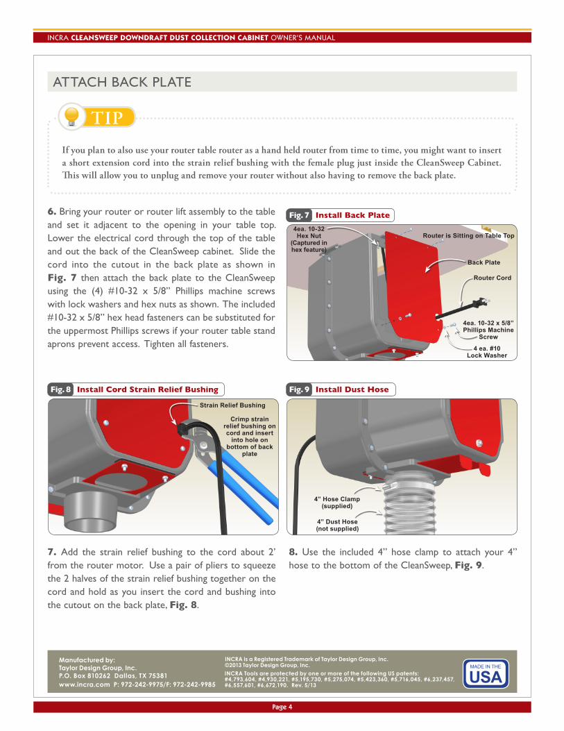
ATTACH BACK PLATE
6. Bring your router or router lift assembly to the table and set it adjacent to the opening in your table top. Lower the electrical cord through the top of the table and out the back of the CleanSweep cabinet. Slide the cord into the cutout in the back plate as shown in Fig. 7 then attach the back plate to the CleanSweep using the (4) #10-32 x 5/8” Phillips machine screws with lock washers and hex nuts as shown. The included #10-32 x 5/8” hex head fasteners can be substituted for the uppermost Phillips screws if your router table stand aprons prevent access. Tighten all fasteners.
If you plan to also use your router table router as a hand held router from time to time, you might want to insert a short extension cord into the strain relief bushing with the female plug just inside the CleanSweep Cabinet. This will allow you to unplug and remove your router without also having to remove the back plate.
TIP
Fig. 8 Install Cord Strain Relief Bushing
Crimp strain relief bushing on cord and insert
into hole on bottom of back
plate
Strain Relief Bushing
Fig. 9 Install Dust Hose
4” Dust Hose(not supplied)
4” Hose Clamp(supplied)
7. Add the strain relief bushing to the cord about 2’ from the router motor. Use a pair of pliers to squeeze the 2 halves of the strain relief bushing together on the cord and hold as you insert the cord and bushing into the cutout on the back plate, Fig. 8.
8. Use the included 4” hose clamp to attach your 4” hose to the bottom of the CleanSweep, Fig. 9.