increased - the arctic chiller group
TRANSCRIPT

www.danfoss.com/mcx
IncreasedNon Standard Part Load Value
of your chiller with smooth and stable operation at any capacity range
4Danfoss Turbocor
Compressors can be managed in your chiller by MCX programmable controller
MCX Turbocor Compound Capacity Controller user manual
Your entire chiller system is fully optimizedwith only one MCX controller
MAKING MODERN LIVING POSSIBLE

User manual Danfoss Turbocor T3C Chiller Standard Software
Index1.0 Introduction 52.0 Compressor control 6
2.1 Chiller states 6
2.2 Individual compressor states 7
2.3 Alarm handling 8
2.4 Economizer 9
2.5 Compressor start procedure 9
2.6 Selection of start-up procedure 11
3.0 Configuration 123.1 OEM customization 12
3.2 Input/output configuration 12
3.2.1 Digital inputs 12
3.2.2 Digital outputs 17
3.2.3 Analog inputs 19
3.2.4 Analog outputs 22
3.3 Parameters for unit configuration 23
3.3.1 Configuration parameters 24
3.3.2 Parameters for compressor configuration 25
3.3.3 Parameters for evaporator configuration 28
3.3.4 Evaporator flow switch 30
3.3.5 Parameters for chiller safety configuration 31
3.3.6 Parameters for input calibration 34
3.4 User interface 35
3.4.1 Main screen 35
3.4.2 Menu navigation 35
3.4.3 Keyboard 38
3.5 “Main switch” 40
3.6 Cooling enable input 41
3.7 Interlock - inputs and outputs 42
3.8 Compressor control 43
3.8.1 Control of the cold side (PID) 47
3.8.2 Compressor start/stop criterion (urgency zone) 47
3.8.3 Hot gas bypass for start-up and load balancing 48
3.8.4 Hot gas bypass solenoid valves for start-up 49
3.8.5 Economizer 51
3.8.6 Power signals for external monitoring (analog and digital) 53
3.9 Evaporator control 54
3.9.1 Liquid solenoide valve 54
3.9.2 Level injection control 54
3.10 Evaporator water pump(s) 56
3.11 Heaters 57
3.11.1 Heaters in cooling mode: anti freeze control 57
2 DKRCC.PS.RI0.B3.02 / 520H6000 Danfoss Electronic Controllers & Services, AZ Feb. 2012

User manual Danfoss Turbocor T3C Chiller Standard Software
3.12 Condenser control 58
3.12.1 Condenser configuration 58
3.12.2 Condenser reference 61
3.12.3 Parameters for condenser control 62
3.12.4 Air condensing unit 64
3.12.5 Step regulation in cooling 64
3.12.6 Fan speed regulation 65
3.12.7 Fan speed regulation + water valve 65
3.13 Condenser pump 67
3.14 Adiabatic/evaporative condenser controls 68
3.15 Water free-cooling 69
3.15.1 Used parameters 70
3.15.2 Free-cooling valve management 71
3.15.3 Fan management in free-cooling 72
3.16 Heat recovery 73
3.16.1 Load limit – compressor power limitation 73
3.16.2 High load but low pressure ratio 75
3.17 Auxiliary inputs/outputs and alarms 76
3.17.1 Auxiliary digital inputs 76
3.17.2 Auxiliary analogue inputs 77
3.17.3 Mirrored analog inputs to analog outputs 78
4.0 Alarms 794.1 Alarm actions 79
4.2 Reset types 79
4.3 Alarm table 79
4.4 Main alarms description 80
5.0 Parameters 885.1 Parameters table 88
6.0 Modbus communication 896.1 Units on Modbus 89
6.2 Exported variables table 89
7.0 Graphic diagrams of some of the managed unit types 907.1 Air/Water 90
7.2 Water/Water 91
8.0 Appendix – configurator usage 928.1 Adapter installation 92
8.2 Guide for application software modification 93
8.3 “Parameters” tab 93
8.4 “Alarms” tab 94
8.5 “Parameters_x_Model” tab 94
8.6 Inputs/outputs configuration tabs 95
8.7 Menu screenshots examples 96
Danfoss Electronic Controllers & Services, AZ Feb. 2012 3DKRCC.PS.RI0.B3.02 / 520H6000

User manual Danfoss Turbocor T3C Chiller Standard Software
Reference:www.danfoss.com/mcx www.turbocor.com
Hardware Network Specification - V 1.0 DKRCC.PS.RI.C1.02 / 520H4636 - Hardware Network Specification - V 1.0
4 DKRCC.PS.RI0.B3.02 / 520H6000 Danfoss Electronic Controllers & Services, AZ Feb. 2012

User manual Danfoss Turbocor T3C Chiller Standard Software
1.0 IntroductionThe Turbocor Compound Capacity Controller (MCX T3C) is dedicated to systems with one or more Danfoss Turbocor compressors. The controller takes care of entire chiller system.
The algorithm allows the management of chiller cooling: Air/Water, Water/Water, Air/Air 1 refrigerant circuit and totally up to 4 Danfoss Turbocor compressors.Because of the algorithm capability to manually assign inputs and outputs according to the unit’s features to control, it is suitable to be executed in any MCX electronic controller, but inputs/outputs requirements normally would demand a MCX15 or MCX20.
The main algorithm’s functions are as follows:
• chilled inlet or outlet water temperature regulation; • proportional/integral regulation; • anti freeze control; • Danfoss Turbocor compressor management; • pre-emptive handling of low evaporator or high discharge pressure; • twin pumps control; • alarms management; • setpoint management:
Ř second setpoint; Ř remote setpoint; Ř setpoint compensation;
• liquid level control; • fan control (step or variable speed); • auto/manual control modes; • historical alarm list.
Fig 1 [Introduction - MCX Turbocor]
Danfoss Electronic Controllers & Services, AZ Feb. 2012 5DKRCC.PS.RI0.B3.02 / 520H6000

User manual Danfoss Turbocor T3C Chiller Standard Software
2.0 Compressor control
2.1 Chiller states
Fig 2 [Compressor control - Chiller state]
• Idle State: the chiller is standing idle (zero capacity) but is ready for start of the first compressor. • Start State: the pressure ratio must be kept low while one or more compressors are in the process
of starting. The start state maintains the low pressure ratio until all running compressors have reached sufficient speed to operate without risk of surging. At that point, the state is changed into the operational state.
• Operational State: the chiller is in normal operation. • Stage-in State: starting a compressor when other compressors are already running requires some
care because the pressure ratio has to be low enough to start a compressor. This is the purpose of the stage-in state. The system is instructed to lower the pressure ratio and the rack controller contributes by instructing all running compressors to reduce their capacity (the retreating and hold states of the individual compressor states below. As soon as the pressure ratio has reached the threshold, the new compressor is instructed to start and the state changes into start state.
• Restart State: it is assumed in the stage-in state that the pressure ratio will come down below the threshold where another compressor can be started. However, it must be assumed that this is not always the case (although should not happen in well designed system unless it is a malfunctioning). In that case all compressors will be stopped and restarted together with one additional compressor. In the restart state, all compressors are signalled to stop. As soon as they
6 DKRCC.PS.RI0.B3.02 / 520H6000 Danfoss Electronic Controllers & Services, AZ Feb. 2012

User manual Danfoss Turbocor T3C Chiller Standard Software
have all reached full stop, the controller signals start to all compressors that need to be started and switches into the start state.
• Stage-out State: in the stage-out state, one compressor is instructed to stop in order to reduce capacity. When it has reached full stop, the state switches automatically back to the operational state.
• Shutdown State: the shutdown state is similar to the stage-out state with the sole exception that in this case the last running compressor is being stopped. The shutdown state therefore switches into the idle stage when this compressor reaches full stop.
2.2 Individual compressor states
Fig 3 [Compressor control - Individual compressors states]
• Absent State: a chiller may contain less than the maximum allowed number of compressors. This leaves some of the state machines unused and uninitialized. This is indicated by the absent state.
• Offline State: the offline state indicates that the compressor is not to be started. This can be due to three reasons:
Ř the operator has taken the compressor offline for maintenance; Ř the compressor encountered a fault state which cannot be recovered by the
controller (the operator needs to recycle the power manually); Ř the controller lost its Modbus connection to the compressor.
• Idle State: the compressor is currently idle but it is online and ready for use. • Starting State: the compressor has received a start signal and is in the process of speeding up.
The state automatically switches into the operational state when the compressor reaches sufficient speed to operate normally without risk of surging.
• Operational State: the compressor is in normal operation. • Stopping State: the compressor has received a stop signal and is in the process of slowing down.
The state automatically switches into the idle state when the compressor reaches full stop. • Retreating State: compressors cannot be started against a high pressure ratio. Thus it is
sometimes necessary to bring the pressure ratio down before another compressor can be started. It is advisable to do this as quickly as possible so that the interruption of the normal operation is reduced to a minimum. This involves the entire chiller (for example utilizing condenser and bypass valves). The compressors that are already running can help by reducing their power as much as possible. This is implemented as the retreating state: power is reduced as long as the pressure ratio is too high to start another compressor. It automatically switches into the hold state as soon as thethreshold is reached.
Danfoss Electronic Controllers & Services, AZ Feb. 2012 7DKRCC.PS.RI0.B3.02 / 520H6000
User manual Danfoss Turbocor T3C Chiller Standard Software
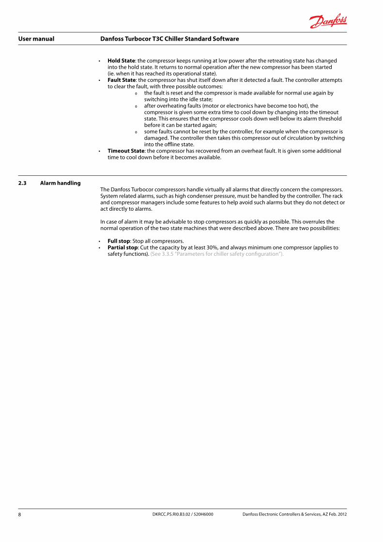
• Hold State: the compressor keeps running at low power after the retreating state has changed into the hold state. It returns to normal operation after the new compressor has been started (ie. when it has reached its operational state).
• Fault State: the compressor has shut itself down after it detected a fault. The controller attempts to clear the fault, with three possible outcomes:
Ř the fault is reset and the compressor is made available for normal use again by switching into the idle state;
Ř after overheating faults (motor or electronics have become too hot), the compressor is given some extra time to cool down by changing into the timeout state. This ensures that the compressor cools down well below its alarm threshold before it can be started again;
Ř some faults cannot be reset by the controller, for example when the compressor is damaged. The controller then takes this compressor out of circulation by switching into the offline state.
• Timeout State: the compressor has recovered from an overheat fault. It is given some additional time to cool down before it becomes available.
2.3 Alarm handlingThe Danfoss Turbocor compressors handle virtually all alarms that directly concern the compressors. System related alarms, such as high condenser pressure, must be handled by the controller. The rack and compressor managers include some features to help avoid such alarms but they do not detect or act directly to alarms.
In case of alarm it may be advisable to stop compressors as quickly as possible. This overrules the normal operation of the two state machines that were described above. There are two possibilities:
• Full stop: Stop all compressors. • Partial stop: Cut the capacity by at least 30%, and always minimum one compressor (applies to
safety functions). (See 3.3.5 “Parameters for chiller safety configuration”).
8 DKRCC.PS.RI0.B3.02 / 520H6000 Danfoss Electronic Controllers & Services, AZ Feb. 2012
User manual Danfoss Turbocor T3C Chiller Standard Software
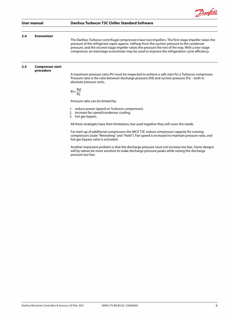
2.4 EconomizerThe Danfoss Turbocor centrifugal compressors have two impellers. The first-stage impeller raises the pressure of the refrigerant vapor approx. halfway from the suction pressure to the condenser pressure, and the second-stage impeller raises the pressure the rest of the way. With a two-stage compressor, an interstage economizer may be used to improve the refrigeration cycle efficiency.
2.5 Compressor start procedure
A maximum pressure ratio (Pr) must be respected to achieve a safe start for a Turbocor compressor. Pressure ratio is the ratio between discharge pressure (Pd) and suction pressure (Ps) – both in absolute pressure units.
Pr=-PdPs
Pressure ratio can be limited by:
1. reduce power (speed on Turbocor compressor);2. increase fan speed/condenser cooling;3. hot gas bypass.
All three strategies have their limitations, but used together they will cover the needs.
For start-up of additional compressors the MCX T3C reduce compressor capacity for running compressors (state “Retreating” and “Hold”). Fan speed is increased to maintain pressure ratio, and hot gas bypass valve is activated.
Another important problem is that the discharge pressure must not increase too fast. Some designs will by nature be more sensitive to make discharge pressure peaks while raising the discharge pressure too fast.
Danfoss Electronic Controllers & Services, AZ Feb. 2012 9DKRCC.PS.RI0.B3.02 / 520H6000

User manual Danfoss Turbocor T3C Chiller Standard Software
These problems are the purpose of the chiller stage-in state. The system is instructed to lower the pressure ratio. The rack controller contributes by instructing all running compressors to reduce their capacity (the retreating and hold states of the individual compressor states). As soon as the pressure ratio has reached the threshold, the new compressor is instructed to start and the state change into start state. If the threshold can not be reached within a predefined time, then all compressors are switched off, and they will all start together from zero rpm.
When the compressor has received a start signal it start the process of open IGV and speeding up. The Danfoss Turbocor compressor has a mode: Before “Start speed reached”. When this operation mode has elapsed then the compressor can be controlled by external capacity demand (here by the MCX T3C).
When the compressor leave the Before “Start speed reached” period, MCX T3C has a following start up procedure. This procedure can be omitted by parameter definitions, but it is recommended not to be omitted. Following is a more detailed description.
Turbocor start procedure:when the compressor is idle and demand get bigger than 0%, then the Turbocor compressor starts as described in the Turbocor software release note PSS-SRN-00010, Rev 1, a sequence diagram from the release note.
T3C start up procedure is made in this way:Turbocor Modbus parameters “41822 – speed acceleration..), and Danfoss Turbocor Modbus parameter 42061 “Start IGV” is set by user at commission time. A start demand is used to speed up the compressor to “Start speed” (Turbocor Modbus parameter 42039). Start demand is defined by T3C parameter.
“t04” “Demand at startup”
The compressor starts and IGV start to open or continue from Danfoss Turbocor Modbus parameter 42061 “Start IGV” position. When IGV has reached an opening % defined by T3C parameter.
“t10“ “IGV start”
Then T3C start sequence T3C is finished. During start up T3C will stay in state “Start” or “Stage-in”, The starting compressor will be in state “Starting” while other running compressors will be in state “hold” until the starting compressor has finished start-up. Then they will all go into operational and demand will be controlled according to actual load demand (PID controlled).
If one or two bypass start solenoids are present, then they will be open during T3C compressor state “Starting”. When the “Starting” state has finished then the first bypass start solenoid is closed. If two solenoids are present then the second solenoid will be closed after an additional delay time defined by parameter “t17” “Bypass solenoid delay”.
10 DKRCC.PS.RI0.B3.02 / 520H6000 Danfoss Electronic Controllers & Services, AZ Feb. 2012

User manual Danfoss Turbocor T3C Chiller Standard Software
2.6 Selection of start-up procedure
1. If T3C parameter “t10” is set to a value below Danfoss Turbocor parameter “Start IGV” (Modbus 42061), then T3C will start procedure will elapse immediately after Turbocor start up has elapsed.Start-up is maintained by Turbocor.
2. Else if T3C parameter “t10” is set to a value above Danfoss Turbocor parameter “Start IGV” (Modbus 42061), then the T3C will continue the start procedure to make the IGV open to a safe position (away from surge). A high start speed (Turbocor Modbus parameter 42039 “Start speed”) produce a lot of power which can make the continued opening of IGV impossible. When in IGV capacity mode the IGV will open on increasing demand and close on decreasing demand, (see - "Turbocor software release note PSS-SRN-00010"), Rev 1, a sequence diagram from the release, (see the image below - "Turbocor software release note PSS-SRN-00010, Rev 1").
If start speed is too high, the demand modulation during compressor START state will lead to closing the IGV instead of opening it more. This is due to the fact that the controller tries to keep speed above surge speed but not too high.
Therefore it is recommended to set Danfoss Turbocor parameter “Start speed” (Turbocor Modbus parameter 42039) to a low value like 20.000 rpm. The T3C controller will smoothly increase capacity following the surge line with a safe margin. This procedure is needed for chillers using micro channel condensers because the discharge pressure otherwise will rise and peak into unsafe area.
Fig 4 [Compressor control - Turbocor software release note PSS-SRN-00010, Rev 1]
Danfoss Electronic Controllers & Services, AZ Feb. 2012 11DKRCC.PS.RI0.B3.02 / 520H6000

User manual Danfoss Turbocor T3C Chiller Standard Software
3.0 Configuration
3.1 OEM customization
The controller can be adapted in several ways to fit into an OEM production line. Parameters can be defined with dedicated factory defaults and texts. Menu can be customized; manufacturer’s brand name and/or logo can be defined. Alarms can be customized.
(See Error! Reference source not found. page Error! Bookmark not defined).
Product Information Description
nf1 Customer Put in your brand name or your customers name, the text will show up on power up of the controller
nf2 Turbocor Chiller Application text
nf3 Configuration version number
Version number, could be used for your identification from remote access
nf4 Not used
nf5 Developed by Danfoss Developed by Danfoss. text could also be your brand name
nf6 Manufacturers logo Default logo is Danfoss, but your logo or logo’s can be created. If you have a series of big customers you could have their logo’s selectable from this parameter
Tab 1 [Configuration - Product information]
3.2 Input/output configuration
3.2.1 Digital inputsTo make the most of the hardware controller resources, you can manually assign the function performed by each controller’s input and output through the software configuration tool “MCXShape.exe” provided together with the application software. (See 8.0 “Appendix - configurator usage”).
Follow below the complete list of the available functions that can be independently assigned to each input and output.
Code Description Digital inputs function
ONO MainSwitch If input is setup, then then the Main switch function will be OFF if either the parameter (“CMS” “Main switch”) or the input is OFF
Cen Cooling enable External input for Cooling enable. Will be read if “cce” “Cooling Enable” is in AUTO
IC1 Cond Invter1 Overld Alarm input for Inverter. Set the alarm “A43” “Inverter fan 1 overload alarm”
FC1 Cond Fan1 Overld Alarm input for Fan. Set the alarm “A44” “Condenser fan 1 overload alarm”
FC2 Cond Fan2 Overld Alarm input for Fan. Set the alarm “A45” “Condenser fan 2 overload alarm”
12 DKRCC.PS.RI0.B3.02 / 520H6000 Danfoss Electronic Controllers & Services, AZ Feb. 2012

User manual Danfoss Turbocor T3C Chiller Standard Software
Code Description Digital inputs function
FC3 Cond Fan3 Overld Alarm input for Fan. Set the alarm “A46” “Condenser fan 3 overload alarm”
FC4 Cond Fan4 Overld Alarm input for Fan. Set the alarm “A47” “Condenser fan 4 overload alarm”
FC5 Cond Fan5 Overld Alarm input for Fan. Set the alarm “A48” “Condenser fan 5 overload alarm”
FC6 Cond Fan6 Overld Alarm input for Fan. Set the alarm “A49” “Condenser fan 6 overload alarm”
FC7 Cond Fan7 Overld Alarm input for Fan. Set the alarm “A50” “Condenser fan 7 overload alarm”
FC8 Cond Fan8 Overld Alarm input for Fan. Set the alarm “A51” “Condenser fan 8 overload alarm”
PC1 Cond Pump Overld Cond Pump Overld
HP1 HP 1 High pressure safety input. Set the alarm “A20” “HP 1 cutout alarm”
HP2 HP 2 Not used
HP3 HP 3 Not used
HP4 HP 4 Not used
LP1 LP 1 Low pressure safety input. Set the alarm “A18” “LP 1 cutout alarm”
FPE Flow Evaporator Evaporator flow switch input. Set the alarm “A03” “Evaporator flow switch alarm”
PEC Evap Pump Ovld Common alarm for 2 Evaporator pumps. Set the alarm “A23” “Evaporator pump overload”
PE1 Evap Pump1 Ovld Individual alarm for Evaporator pump 1 – Used also for single pump systems. Set the alarm “A24” “Evaporator pump 1 overload”
PE2 Evap Pump2 Ovld Individual alarm for Evaporator pump 2 – Used also for single pump systems. Set the alarm “A25” “Evaporator pump 2 overload”
FPC Flow Condenser Condenser flow switch input. Set the alarm “A04” “Condenser flow switch alarm”
ST2 Remote Offset Enable
Make an offset to Cold set point. Offset is defined by parameter “h02” “digital input offset”
ST3 Remote Setpoint Enable
Enable remote setpoint
MCL max current limit External load limit by a value defined by parameter “t08” “External load limit”
OHC Heaters Ovld C1 Common alarm input for all heaters. Set the alarm“A78” “Evaporator heaters overload”
OH1 Heater1 Overload Individual heater alarm. Set the alarm“A79” “Evaporator heater 1 overload”
OH2 Heater2 Overload Individual heater alarm. Set the alarm“A80” “Evaporator heater 2 overload”
Danfoss Electronic Controllers & Services, AZ Feb. 2012 13DKRCC.PS.RI0.B3.02 / 520H6000

User manual Danfoss Turbocor T3C Chiller Standard Software
Code Description Digital inputs function
OH3 Heater3 Overload Individual heater alarm. Set the alarm“A81” “Evaporator heater 3 overload”
OH4 Heater4 Overload Individual heater alarm. Set the alarm“A82” “Evaporator heater 4 overload”
GA1 General alarm 1 Digital input for General purpose alarm. Set the alarm“A53” “General DI alarm 1”
GA2 General alarm 2 Digital input for General purpose alarm. Set the alarm“A54” “General DI alarm 2”
GA3 General alarm 3 Digital input for General purpose alarm. Set the alarm“A55” “General DI alarm 3”
GA4 General alarm 4 Digital input for General purpose alarm. Set the alarm“A56” “General DI alarm 4”
GA5 General alarm 5 Digital input for General purpose alarm. Set the alarm“A57” “General DI alarm 5”
GA6 General alarm 6 Digital input for General purpose alarm. Set the alarm“A58” “General DI alarm 6”
GA7 General alarm 7 Digital input for General purpose alarm. Set the alarm“A59” “General DI alarm 7”
GA8 General alarm 8 Digital input for General purpose alarm. Set the alarm“A60” “General DI alarm 8”
GA9 General alarm 9 Digital input for General purpose alarm. Set the alarm“A61” “General DI alarm 9”
GAa General alarm 10 Digital input for General purpose alarm. Set the alarm“A62” “General DI alarm 10”
TT0 TT Interlock common
Interlock input, (see section - “Error! Reference source not found.” page Error! Bookmark not defined)
TT1 TT interlock 1 Interlock input, (see section - “Error! Reference source not found.” page Error! Bookmark not defined)
TT2 TT interlock 2 Interlock input, (see section - “Error! Reference source not found.” page Error! Bookmark not defined)
TT3 TT interlock 3 Interlock input, (see section - “Error! Reference source not found.” page Error! Bookmark not defined)
TT4 TT interlock 4 Interlock input, (see section - “Error! Reference source not found.” page Error! Bookmark not defined)
CT1 Adiabatic pump overload
Stop the pump if parameter “ct1” “Evaporative condenser control” is in AUTO. Set the alarm “A85” “Adiabatic Pump overload”
CT2 Cooling tower heater overload
Set the alarm “A84” “Evap. Condenser heaters”
CT3 Cooling tower water level
Stop the pump if parameter “ct1” “Evaporative condenser control” is in AUTO. Set the alarm “A83” “Evap. Condenser water level”
PL1 External load shedding
Limit maximum power to a value defined by parameter
DL1 Digital liquid level low C1
Digital Liquid level signal, used for Two point liquid level control
14 DKRCC.PS.RI0.B3.02 / 520H6000 Danfoss Electronic Controllers & Services, AZ Feb. 2012

User manual Danfoss Turbocor T3C Chiller Standard Software
Code Description Digital inputs function
DL2 Digital liquid level low C2
Digital Liquid level signal, used for Two point liquid level control
DH1 Digital liquid level high C1
Not used
DH2 Digital liquid level high C2
Not used
PHS Phase/Sequence alarm
Input from a Phase monitoring device. Make a MainSwitch OFF function and set the alarm “A91” “Phase/Sequence alarm”
XE1 Auxiliary Input Enable 1
Input to enable auxiliary alarm function.(See 3.17 “Auxiliary inputs/outputs and alarms”)
XE2 Auxiliary Input Enable 2
Input to enable auxiliary alarm function.(See 3.17 “Auxiliary inputs/outputs and alarms”)
XE3 Auxiliary Input Enable 3
Input to enable auxiliary alarm function.(See 3.17 “Auxiliary inputs/outputs and alarms”)
XE4 Auxiliary Input Enable 4
Input to enable auxiliary alarm function.(See 3.17 “Auxiliary inputs/outputs and alarms”)
XE5 Auxiliary Input Enable 5
Input to enable auxiliary alarm function.(See 3.17 “Auxiliary inputs/outputs and alarms”)
XE6 Auxiliary Input Enable 6
Input to enable auxiliary alarm function.(See 3.17 “Auxiliary inputs/outputs and alarms”)
XE7 Auxiliary Input Enable 7
Input to enable auxiliary alarm function.(See 3.17 “Auxiliary inputs/outputs and alarms”)
ALR Alarm Reset Reset all alarms
HRE Heat Recovery Enable
Enable the Heat recovery functionnot implemented
Tab 2 [Configuration - Digital inputs configuration]
Danfoss Electronic Controllers & Services, AZ Feb. 2012 15DKRCC.PS.RI0.B3.02 / 520H6000

User manual Danfoss Turbocor T3C Chiller Standard Software
Configuration example for External Main switch, but valid in general
Conditions Signal inputs/outputs status menu
Flow switch alarm
DI7 - NO (Normally Open) 0 Vac 0 OFF
DI7 - NO (Normally Open) 24 Vac 1 ON 1)
DI7 - NC (Normally Closed) 0 Vac 1 ON 2)
DI7 - NC (Normally Closed) 24 Vac 0 OFF
1) If External Main switch is wanted for a closed contactor then chose NC2) If External Main switch is wanted for a open contactor then chose NO
Tab 3 [Configuration - Configuration example]
Digital input for Flow Evaporator Digital input for Flow Condenser
Conditions Signal inputs/outputs status menu
Flow switch alarm
DI7 - NO (Normally Open) 0 Vac 0 OK 1)
DI7 - NO (Normally Open) 24 Vac 1 Alarm
DI7 - NC (Normally Closed) 0 Vac 1 alarm
DI7 - NC (Normally Closed) 24 Vac 0 OK 2)
1) If flow is present and flow contactor is open, then chose NO2) If flow is present and flow contactor is closed, then chose NC
Tab 4 [Configuration - Digital input for flow evaporatorand condenser]
Contactor problems:
• it is expected that the contact leakage current is low or zero. If problems, please measure signal on MCX input and make your judgement.
16 DKRCC.PS.RI0.B3.02 / 520H6000 Danfoss Electronic Controllers & Services, AZ Feb. 2012

User manual Danfoss Turbocor T3C Chiller Standard Software
3.2.2 Digital outputs
Code Description Digital outputs function
PE1 Evap Pump1 Evaporator pump 1
PE2 Evap Pump2 Evaporator pump 2
LS1 LLS circuit 1 Liquid line solenoid for circuit 1
LS2 LLS circuit 2 Liquid line solenoid for circuit 2 – NOT USED
FC1 Condenser Fan1 Condenser Fan 1
FC2 Condenser Fan2 Condenser Fan 2
FC3 Condenser Fan3 Condenser Fan 3
FC4 Condenser Fan4 Condenser Fan 4
FC5 Condenser Fan5 Condenser Fan 5
FC6 Condenser Fan6 Condenser Fan 6
FC7 Condenser Fan7 Condenser Fan 7
FC8 Condenser Fan8 Condenser Fan 8
FI1 Inverter Cond1
PC1 Condenser Pump 1 Condenser Pump 1
PC2 Condenser Pump 2 Condenser Pump 2
TT1 TT interlock 1 Individual interlock to compressor 1
TT2 TT interlock 2 Individual interlock to compressor 2
TT3 TT interlock 3 Individual interlock to compressor 3
TT4 TT interlock 4 Individual interlock to compressor 4
H1 Heater1 Heater output 1
H2 Heater2 Heater output 2
H3 Heater3 Heater output 3
H4 Heater4 Heater output 4
XD1 General DI alarm 1 Optional output for general digital input alarm 1
XD2 General DI alarm 2 Optional output for general digital input alarm 2
XD3 General DI alarm 3 Optional output for general digital input alarm 3
XD4 General DI alarm 4 Optional output for general digital input alarm 4
XD5 General DI alarm 5 Optional output for general digital input alarm 5
XD6 General DI alarm 6 Optional output for general digital input alarm 6
XD7 General DI alarm 7 Optional output for general digital input alarm 7
XD8 General DI alarm 8 Optional output for general digital input alarm 8
XD9 General DI alarm 9 Optional output for general digital input alarm 9
XDa General DI alarm 10 Optional output for general digital input alarm 10
Danfoss Electronic Controllers & Services, AZ Feb. 2012 17DKRCC.PS.RI0.B3.02 / 520H6000

User manual Danfoss Turbocor T3C Chiller Standard Software
Code Description Digital outputs function
XA1 Auxiliary DO 1 Optional output for auxiliary thermostat input alarm 1
XA2 Auxiliary DO 2 Optional output for auxiliary thermostat input alarm 2
XA3 Auxiliary DO 3 Optional output for auxiliary thermostat input alarm 3
XA4 Auxiliary DO 4 Optional output for auxiliary thermostat input alarm 4
XA5 Auxiliary DO 5 Optional output for auxiliary thermostat input alarm 5
XA6 Auxiliary DO 6 Optional output for auxiliary thermostat input alarm 6
XA7 Auxiliary DO 7 Optional output for auxiliary thermostat input alarm 7
ALR Alarm Alarm relay
WAR Warning Warning Relay
EC1 Economizer compressor 1
Economizer start relay for compressor 1
EC2 Economizer compressor 2
Economizer start relay for compressor 1
EC3 Economizer compressor 3
Economizer start relay for compressor 1
EC4 Economizer compressor 4
Economizer start relay for compressor 1
FR1 Free cooling valve 1 Free cooling start relay
CT4 Adiabatic pump Start adiabatic pump
CT5 Cooling tower heater
Start cooling tower heater
AHP HP alarm High pressure alarm
ALP LP alarm Low pressure alarm
ACC Compressor alarm common
Common compressor alarm
CON Compressor running
Status relay for minimum one compressor is running
CO1 Compressor 1 running
Status relay for compressor 1 running
CO2 Compressor 2 running
Status relay for compressor 2 running
CO3 Compressor 3 running
Status relay for compressor 3 running
CO4 Compressor 4 running
Status relay for compressor 4 running
BS1 Bypass Solenoid 1a Hotgas bypass solenoid for compressor 1 – first relay
BS2 Bypass Solenoid 2a Hotgas bypass solenoid for compressor 1 – second relay (delayed stop)
BS3 Bypass Solenoid 3a Hotgas bypass solenoid for compressor 2 – first relay
BS4 Bypass Solenoid 4a Hotgas bypass solenoid for compressor 2 – second relay (delayed stop)
18 DKRCC.PS.RI0.B3.02 / 520H6000 Danfoss Electronic Controllers & Services, AZ Feb. 2012

User manual Danfoss Turbocor T3C Chiller Standard Software
Code Description Digital outputs function
BS5 Bypass Solenoid 1b Hotgas bypass solenoid for compressor 3 – first relay
BS6 Bypass Solenoid 2b Hotgas bypass solenoid for compressor 3 – second relay (delayed stop)
BS7 Bypass Solenoid 3b Hotgas bypass solenoid for compressor 4 – first relay
BS8 Bypass Solenoid 4b Hotgas bypass solenoid for compressor 4 – second relay (delayed stop)
FA0 Minimum active power status
FA1 Flow evaporator alarm
Alarm status for evaporator water flow (alarm “A03”)
FA2 Flow condenser alarm
Alarm status for condenser water flow (alarm “A04”)
FA3 Low water temperature alarm
Alarm status for Low evaporator water temperature (alarm “A30”)
FA4 Low suction press. alarm
Alarm status for Low suction pressure (alarm “A31”)
FA5 High discharge press. alarm
Alarm status for High discharge pressure (alarm “A32”)
FA6 General alarm Comp. 1
T3C: Compressor in state fault
FA7 General alarm Comp. 2
T3C: Compressor in state fault
FA8 General alarm Comp. 3
T3C: Compressor in state fault
FA9 General alarm Comp. 4
T3C: Compressor in state fault
HRV Heat Recovery Enable Valve
Heat recovery start valve
Tab 5 [Configuration - Digital outputs]
3.2.3 Analog inputs
Code Description Analog inputs function
EW1 Entering chilled water
Entering chilled water
LWT Leaving chilled water
Leaving chilled water
LW1 Leaving chilled water C1
Leaving chilled water circuit 1 (backup sensor for single circuit chillers)
LW2 Leaving chilled water C2
Leaving chilled water circuit 2 – future use
TOM Entering condenser water
Entering condenser water
Danfoss Electronic Controllers & Services, AZ Feb. 2012 19DKRCC.PS.RI0.B3.02 / 520H6000

User manual Danfoss Turbocor T3C Chiller Standard Software
Code Description Analog inputs function
TC1 Leaving condenser water
Leaving condenser water
TrO Remote Offset Remote offset to control setpoint
TrS Remote Setpoint Remote setpoint
Tou Toutside Ambient temperature (used for setpoint offset compensation)
TcO Condenser reference offset
Condenser reference offset
Po1 Suction Pressure 1 BarA
Optional Suction pressure transmitter – Bar AbsoluteIf not present, then the internal Turbocor pressure transmitter will be used.
Pc1 Discharge Pressure 1 BarA
Optional Discharge pressure transmitter – Bar Absolute If not present, then the internal Turbocor pressure transmitter will be used.
HE1 Tout Condenser1
Lv1 Level control 1 Liquid level input 0-100% for circuit 1
Lv2 Level control 2 Liquid level input 0-100% for circuit 2 NOT USED
Ga0 Auxiliary input 1 Input for Auxiliary thermostat 1
Ga1 Auxiliary input 2 Input for Auxiliary thermostat 2
Ga2 Auxiliary input 3 Input for Auxiliary thermostat 3
Ga3 Overheating T Aux4 Input for Auxiliary thermostat 4
Ga4 Auxiliary input 5 Input for Auxiliary thermostat 5
Ga5 Auxiliary input 6 Input for Auxiliary thermostat 6
Ga6 Auxiliary input 7 Input for Auxiliary thermostat 7
FR1 Freecoling temperature
Input for freecooling
CTo Adiabatic pump offset
PL2 External load shedding
Load shedding % of defined rated power by parameter “TO9”
LL1 Digital liquid level low C1
Low voltage digital inputs for liquid level - circuit 1Low position
LL2 Digital liquid level low C2
Not used
LH1 Digital liquid level high C1
Low voltage digital inputs for liquid level – circuit 1High position
LH2 Digital liquid level high C2
Not used
WIP Inlet Water Pressure Pressure transmitter for inlet evaporator water pressure (Bar Abs.)
WOP Outlet Water Pressure
Pressure transmitter for outlet evaporator water pressure (Bar Abs.)
20 DKRCC.PS.RI0.B3.02 / 520H6000 Danfoss Electronic Controllers & Services, AZ Feb. 2012

User manual Danfoss Turbocor T3C Chiller Standard Software
Code Description Analog inputs function
LT1 Liquid Line Temperature C1
Liquid Line Temperature circuit 1
ST1 Suction Temperature C1
Suction Line Temperature circuit 1
LT2 Liquid Line Temperature C2
Not used
ST2 Suction Temperature C2
Not used
WIC Inlet Water Pressure Condenser
Pressure transmitter for inlet condenser water pressure (Bar Abs.)
WOC Outlet Water Pressure Condenser
Pressure transmitter for outlet condenser water pressure (Bar Abs.)
Pd1 Discharge Pressure TC1 BarA
Monitoring and individual surge detection by individual signals
Pd2 Discharge Pressure TC2 BarA
Monitoring and individual surge detection by individual signals
Pd3 Discharge Pressure TC3 BarA
Monitoring and individual surge detection by individual signals
Pd4 Discharge Pressure TC4 BarA
Monitoring and individual surge detection by individual signals
HRT Heat Recovery Temperature
Not used
Mi1 Generic Mirrored Input 1
Input to be mirrored to Analog output “Generic Mirror Output 1”.(See 3.17.3 "Mirrored analog inputs to analog outputs")
Mi2 Generic Mirrored Input 2
Input to be mirrored to Analog output “Generic Mirror Output 2”
Mi3 Generic Mirrored Input 3
Input to be mirrored to Analog output “Generic Mirror Output 3”
Mi4 Generic Mirrored Input 4
Input to be mirrored to Analog output “Generic Mirror Output 4”
Tab 6 [Configuration - Analog inputs]
Danfoss Electronic Controllers & Services, AZ Feb. 2012 21DKRCC.PS.RI0.B3.02 / 520H6000

User manual Danfoss Turbocor T3C Chiller Standard Software
3.2.4 Analog outputs
Code Description Analog outputs function
FC1 InverterFanCond1 Speed controlled fan
VC1 Valve Cond1 Condenser valve control
VB1 Bypass Valve 1 For hot gas bypass valve (start-up and capacity control)
LE1 Level Valve 1 Liquid level control
LE2 Level Valve 2 Not used
FR1 Free cooling valve 1 Free cooling 3-way valve
Apw Active Power Display current
DPf Discharge Pressure feedback
AO_AI_Pc1
Mo1 Generic Mirror Output 1
AO_Mirror_Output_1
Mo2 Generic Mirror Output 2
AO_Mirror_Output_2
Mo3 Generic Mirror Output 3
AO_Mirror_Output_3
Mo4 Generic Mirror Output 4
AO_Mirror_Output_4
Tab 7 [Configuration - Analog outputs]
22 DKRCC.PS.RI0.B3.02 / 520H6000 Danfoss Electronic Controllers & Services, AZ Feb. 2012

User manual Danfoss Turbocor T3C Chiller Standard Software
3.3 Parameters for unit configuration
The Danfoss Turbocor compressor is controlled by Modbus serial communication. A safe and reliable communication is essential for the control performance:
• correct terminating of the Modbus communication lines; • correct baud rate for MCX slave input (RS485-1); • correct baud rate for MCX master and all Danfoss Turbocor compressors (RS485-2); • correct address setup for individual Danfoss Turbocor compressors.
Modbus communication setup for slave input (e.g. PC to MCX):
ssa - Serial address (Modbus and CAN)Node serial address, valid for both CAN and Modbus network. Each node must have a unique serial address.
Note
SEr change the address after unit power up. SEr always overrule the BIOS setting.
ssb – Serial baud rate (Modbus): • ssb=0. communication OFF; • ssb=12. baud rate=1200 baud; • ssb=24. baud rate=2400 baud; • ssb=48. baud rate=4800 baud; • ssb=96. baud rate=9600 baud; • ssb=144. baud rate=1440 baud; • ssb=192. baud rate=19200 baud; • ssb=288. baud rate=28800 baud; • ssb=384. baud rate=38400 baud.
sss – Serial settings (Modbus): • sss=8N1. 8 bit data, no parity, 1 stop bit; • sss=8E1. 8 bit data, parity even, 1 stop bit; • sss=8N2. 8 bit data, no parity, 2 stop bit.
Danfoss Electronic Controllers & Services, AZ Feb. 2012 23DKRCC.PS.RI0.B3.02 / 520H6000

User manual Danfoss Turbocor T3C Chiller Standard Software
Modbus communication setup for master output (MCX to Danfoss Turbocor compressors):
sm1-sm4 - Serial address (Modbus master)Serial address for Danfoss Turbocor compressor 1- 4. Each node must have a unique serial address.
Note
sm1-sm4 take effect after a new power up of the controller.
Code Serial settings Turbocor
smb Serial baudrate (Modbus)
sms Serial settings (Modbus)
sm1 Serial address device 1
sm2 Serial address device 2
sm3 Serial address device 3
sm4 Serial address device 4
Tab 8 [Configuration - Serial setting Turbocor]
smb – Serial baud rate (Modbus master): • smb=192. baud rate=19200 baud; • smb=384. baud rate=38400 baud.
sms – Serial settings (Modbus master): • sms=8N1. 8 bit data, no parity, 1 stop bit; • sms=8E1. 8 bit data, parity even, 1 stop bit; • sms=8N2. 8 bit data, no parity, 2 stop bit.
3.3.1 Configuration parameters
Configuration parameters are used to define the controller depending on physical environment.
Example
Number of compressors.
Parameters which the daily user must not change.
24 DKRCC.PS.RI0.B3.02 / 520H6000 Danfoss Electronic Controllers & Services, AZ Feb. 2012

User manual Danfoss Turbocor T3C Chiller Standard Software
3.3.2 Parameters for compressor configuration
Code Parameters for compressors
t01 Compressor motor power
t02 Number of compressors
t03 Refrigerant
t04 Demand at startup
t05 Demand at fault reset
t06 Minimum pressure ratio at maximum load
t07 Load shedding percentage
t08 External load shedding percentage
t09 Rated power consumption
t10 IGV start
t11 IGV stop
t12 Stage-in timeout
t13 Minimum hold demand
t15 Reserved compressors
t16 Minimum hold demand
t17 Bypass solenoid delay
t18 Power stop
t19 High Load Low Capacity ctrl enable
t20 Surge detection on power enable
t21 Rotation type
Tab 9 [Configuration - Parameters for compressors]
t01 – Compressor motor powerMust always be set to the individual actual compressor motor power in kW (assuming that they are equal).
t02 – Number of compressorsSet the actual numbers to be connected to the controller.
t03 – RefrigerantRefrigerant type is used to calculate saturated temperatures from measured pressures. Parameter for the selection is “t03” “Refrigerant”. The parameter has 3 selections:
1. NOT selected;2. R22;3. R134A (This selection is default).
If selection is 0 then “Main Switch” will remain OFF, and an alarm will be set (Refrigerant NOT selected). Selection 0 can be used to force a customer to select refrigerant type.
Danfoss Electronic Controllers & Services, AZ Feb. 2012 25DKRCC.PS.RI0.B3.02 / 520H6000

User manual Danfoss Turbocor T3C Chiller Standard Software
t04 – Demand at startupWhen compressors is in starting state it will be given this demand to make a quick startup (starting state. (See 2.2 "Individual compressor states").
t05 – Demand at startupLeft blank by intention
t06 – Minimum pressure ratio at maximum load(See 3.16.2 "High load but low pressure ratio").
t07 – Load shedding percentage
Limiting the full load power consumption with this percentage. 100% is related to “Rated power consumption”.
t08 – External load shedding percentageLimiting the full load power consumption with this percentage when digital input “External load shedding” is active. 100% is related to “Rated power consumption”.
t09 – Rated power consumptionTotal maximum power. Defined by the manufacturer according to actual chiller design. Rated power consumption is internally limited to “t01” * “t02”, same as “Number of compressors” * “Compressor motor power”.
t10 – IGV startIGV opening % at start up. When IGV has reached the opening % then T3C start sequence T3C is finished. (See 2.5 "Compressors start procedure").
t11 – IGV stopIGV position to stop the compressor at low power. (alternative way to avoid surge) (“compressor at minimum” is fixed to 70%, which means that compressor is ready to stage out when stop criteria by urgency zone (neutral zone) is also fulfilled).
t12 – Stage-in timeoutIf the unit has not succeeded to bring down the pressure ratio during start-up with in time specified, the start sequence is changed. All compressors stops to bring down the pressure ratio and then start again.
t13 – Minimum hold demandMinimum demand in percent while in hold state. Demand decreases until pressure ratio is below acceptable level, (see "parameter t16 below"). Capacity to hold while another compressor starts, (see 2.5 "Compressors start procedure"). 30% means that all compressors individually are given a demand of 30 % power. t14 Left blank by intention.
t15 – Reserved compressorsNumber of compressors to keep as backup only: maximum number of compressors running at the same time will be equal to (t20 – t15) . Backup compressors will be used as replacement for compressors stopped on alarm. If runtime equalisation is used ("t21" "Rotation type") then backup compressors will be included.
Note
maximum value is (t02 - 1): one compressor is ALWAYS allowed to start.
t16 – Maximum start pressure ratioPressure ratio to allow compressor start.
t17 – Bypass solenoid delayIf two bypass solenoids are used, this delay is added before closing number 2.
26 DKRCC.PS.RI0.B3.02 / 520H6000 Danfoss Electronic Controllers & Services, AZ Feb. 2012
User manual Danfoss Turbocor T3C Chiller Standard Software
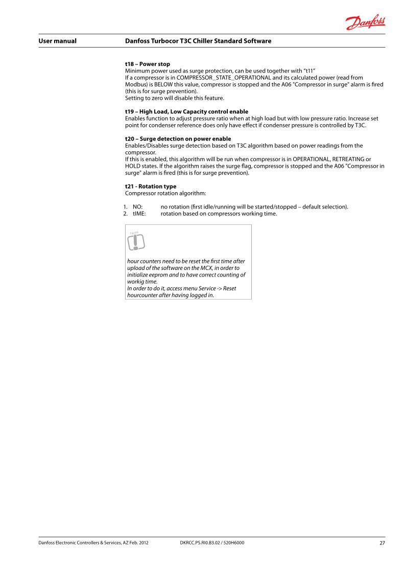
t18 – Power stopMinimum power used as surge protection, can be used together with “t11” If a compressor is in COMPRESSOR_STATE_OPERATIONAL and its calculated power (read from Modbus) is BELOW this value, compressor is stopped and the A06 "Compressor in surge" alarm is fired (this is for surge prevention). Setting to zero will disable this feature.
t19 – High Load, Low Capacity control enableEnables function to adjust pressure ratio when at high load but with low pressure ratio. Increase set point for condenser reference does only have effect if condenser pressure is controlled by T3C.
t20 – Surge detection on power enableEnables/Disables surge detection based on T3C algorithm based on power readings from the compressor. If this is enabled, this algorithm will be run when compressor is in OPERATIONAL, RETREATING or HOLD states. If the algorithm raises the surge flag, compressor is stopped and the A06 "Compressor in surge" alarm is fired (this is for surge prevention).
t21 - Rotation typeCompressor rotation algorithm:
1. NO: no rotation (first idle/running will be started/stopped – default selection).2. tIME: rotation based on compressors working time.
Note
hour counters need to be reset the first time after upload of the software on the MCX, in order to initialize eeprom and to have correct counting of workig time.In order to do it, access menu Service -> Reset hourcounter after having logged in.
Danfoss Electronic Controllers & Services, AZ Feb. 2012 27DKRCC.PS.RI0.B3.02 / 520H6000
User manual Danfoss Turbocor T3C Chiller Standard Software
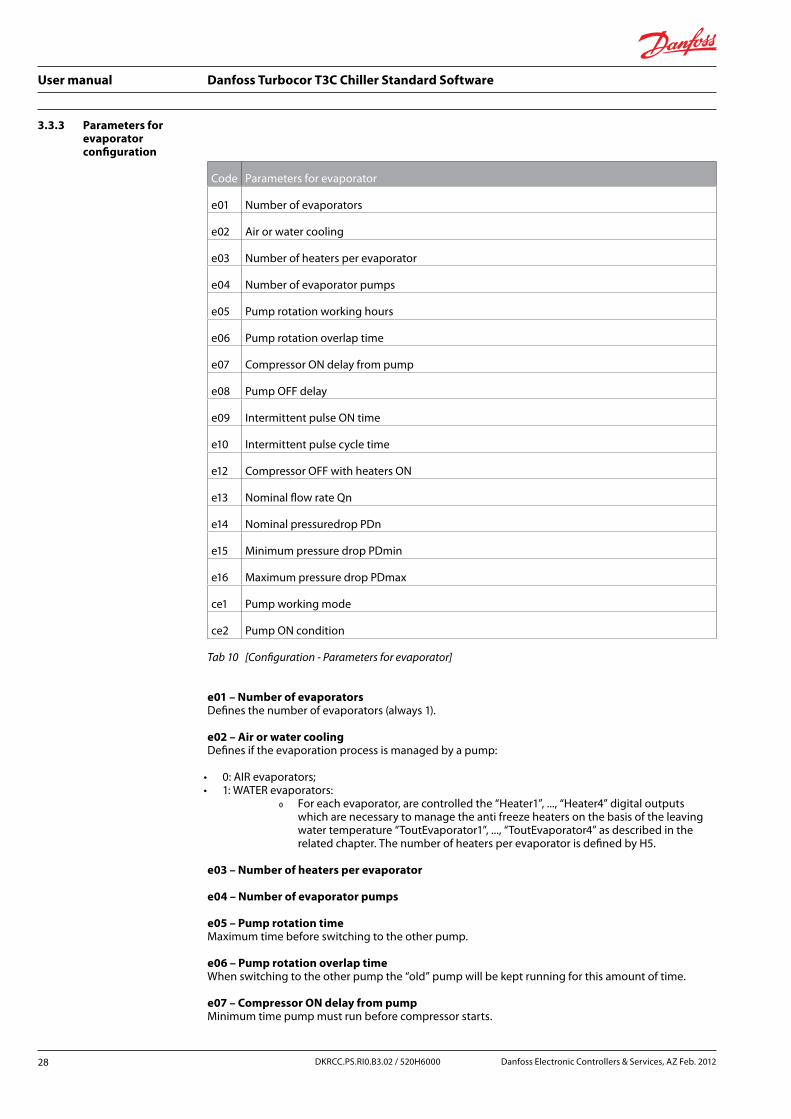
3.3.3 Parameters for evaporator configuration
Code Parameters for evaporator
e01 Number of evaporators
e02 Air or water cooling
e03 Number of heaters per evaporator
e04 Number of evaporator pumps
e05 Pump rotation working hours
e06 Pump rotation overlap time
e07 Compressor ON delay from pump
e08 Pump OFF delay
e09 Intermittent pulse ON time
e10 Intermittent pulse cycle time
e12 Compressor OFF with heaters ON
e13 Nominal flow rate Qn
e14 Nominal pressuredrop PDn
e15 Minimum pressure drop PDmin
e16 Maximum pressure drop PDmax
ce1 Pump working mode
ce2 Pump ON condition
Tab 10 [Configuration - Parameters for evaporator]
e01 – Number of evaporatorsDefines the number of evaporators (always 1).
e02 – Air or water coolingDefines if the evaporation process is managed by a pump:
• 0: AIR evaporators; • 1: WATER evaporators:
Ř For each evaporator, are controlled the “Heater1”, ..., “Heater4” digital outputs which are necessary to manage the anti freeze heaters on the basis of the leaving water temperature “ToutEvaporator1”, ..., “ToutEvaporator4” as described in the related chapter. The number of heaters per evaporator is defined by H5.
e03 – Number of heaters per evaporator
e04 – Number of evaporator pumps
e05 – Pump rotation timeMaximum time before switching to the other pump.
e06 – Pump rotation overlap timeWhen switching to the other pump the “old” pump will be kept running for this amount of time.
e07 – Compressor ON delay from pumpMinimum time pump must run before compressor starts.
28 DKRCC.PS.RI0.B3.02 / 520H6000 Danfoss Electronic Controllers & Services, AZ Feb. 2012

User manual Danfoss Turbocor T3C Chiller Standard Software
e08 – Pump OFF delayTime to let pump run after last compressor has stopped.
e09 – Intermittent pulse ON time
e10 – Intermittent pulse cycle timeWhen pumps have stopped, they can be forced on by frequent intervals defined by parameter “e10”. The ON duration is controlled by “e09” 0: means that they will never be turned on.
e12 – Compressor OFF with heaters ONSelect to Stop compressors when heaters are ON or let the compressors run with heaters ON.
Flow calculation by pressure dropSome parameters and inputs are used to make rough flow estimation and thereby also calculate a rough cooling capacity.
e13 – Nominal flow rate QnThe flow rate at a point defined by “e14” “Nominal pressuredrop PDn”.
e14 – Nominal pressuredrop PDnThe pressure drop rate at a point defined by “e13” “Nominal flow rate Qn”.
e15 – Minimum pressure drop PDminFlow below this value will trigger alarm “A92” “Evaporator low flow rate alarm”.
e16 – Maximum pressure drop PDmaxFlow above this value will trigger alarm “A22” “Evaporator high flow rate alarm”.
ce1 – Pump working modeFor service purposes the user must be able to select the actual pump control mode:
1. no pumps are used;2. pump 1 is running when e06 “Pump ON condition” is satisfied;3. pump 2 is running when e06 “Pump ON condition” is satisfied;4. alternation between pump 1 and pump 2.
If only one pump is configured, pump control mode” in position 2,3 or 4 is not applicable.
ce2 – Pump ON condition For service purposes the user must be able to select the actual pump control mode:
1. “MS”, Start when “Main Switch” is on;2. “CE“ Start when “Chiller enable” input is active;3. “Comp” Start with first compressor.
Danfoss Electronic Controllers & Services, AZ Feb. 2012 29DKRCC.PS.RI0.B3.02 / 520H6000

User manual Danfoss Turbocor T3C Chiller Standard Software
3.3.4 Evaporator flow switch
In water cooled systems the water flow is essential to monitor. Without flow the cooled liquid can freeze within very short time.
There are two options for flow detection:
1. digital signal from a flow switch;2. differential pressure measured by two pressure transmitters.
It is recommended to use minim one of options above.
Digital input “FPE” “Flow Evaporator” is used as input.
Conditions Signal Inputs/outputs status menu
Flow switch alarm
DI7 - NO (Normally Open) 0 Vac 0 OK 1)
DI7 - NO (Normally Open) 24 Vac 1 alarm
DI7 - NC (Normally Closed) 0 Vac 1 alarm
DI7 - NC (Normally Closed) 24 Vac 0 OK 2)
1) If flow is present and flow contactor is open, then chose NO2) If flow is present and flow contactor is closed, then chose NC
Tab 11 [Configuration - Evaporator flow]
1. Differential pressure can also be used if two pressure transmitters are connected. If only one input is allocated then the flow detection function is omitted.
Used inputs are:
• “WIP” “Inlet Water Pressure”; • “WOP” “Outlet Water Pressure”.
Flow/No flow is determined by
Flow is defined as when flow is above “e15” “Minimum pressure drop PDmin”. (See 3.3.3 "Parameters for evaporator configuration").
30 DKRCC.PS.RI0.B3.02 / 520H6000 Danfoss Electronic Controllers & Services, AZ Feb. 2012
User manual Danfoss Turbocor T3C Chiller Standard Software
3.3.5 Parameters for chiller safety configuration
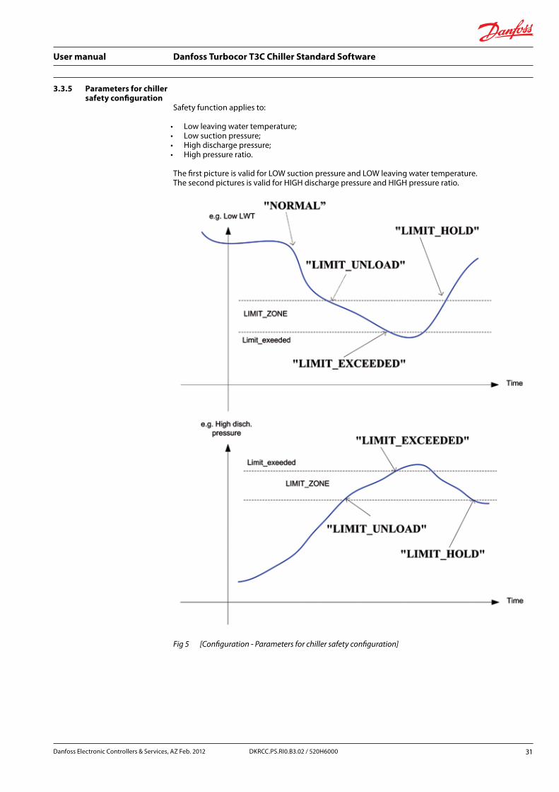
Safety function applies to:
• Low leaving water temperature; • Low suction pressure; • High discharge pressure; • High pressure ratio.
The first picture is valid for LOW suction pressure and LOW leaving water temperature. The second pictures is valid for HIGH discharge pressure and HIGH pressure ratio.
Fig 5 [Configuration - Parameters for chiller safety configuration]
Danfoss Electronic Controllers & Services, AZ Feb. 2012 31DKRCC.PS.RI0.B3.02 / 520H6000
User manual Danfoss Turbocor T3C Chiller Standard Software
Safety functions all make use of same philosophy: • functions are reset when “Main Switch” is OFF (timers, state, alarm); • a limit set point where a radical action is taken - could be to stop compressors; • a narrow band before entering the limit set point where compressor capacity is decreased with a
fixed capacity within fixed time intervals. If required also set the fans to maximum capacity. If signal then get into “normal” area then compressor demand is limited for user defined period of time;
• » The decrease value follow this rule: Stop minimum one compressor. if only one compressor is present then the demand to the compressor is reduced by 33% (minimum one compressor) within fixed time intervals defined by “saa”, “Safety step down time”.
Following states apply to individual safety functions: • NORMAL normal operation without restrictions; • LIMIT_HOLD compressor capacity increase is restricted; • LIMIT_UNLOAD compressor capacity will be decreased, minimum 33% capacity will be
unloaded every 30 sec. Minimum one compressor will stop; • LIMIT_EXCEEDED compressors will stop.
Alarms “StartupDelay” defines the time period after initial power on where the function is suppressed Alarms Delay defines the time for HOLD and restart after LIMIT_EXCEEDED.
Options to disable the functions:
1. set the limit set point value to a value far away from normal limit value;2. sensor/transmitter error for used function;3. defect sensor.
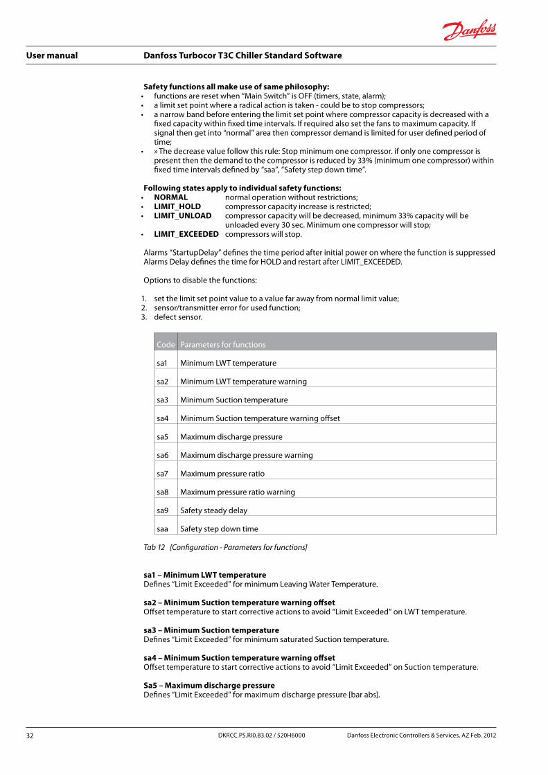
Code Parameters for functions
sa1 Minimum LWT temperature
sa2 Minimum LWT temperature warning
sa3 Minimum Suction temperature
sa4 Minimum Suction temperature warning offset
sa5 Maximum discharge pressure
sa6 Maximum discharge pressure warning
sa7 Maximum pressure ratio
sa8 Maximum pressure ratio warning
sa9 Safety steady delay
saa Safety step down time
Tab 12 [Configuration - Parameters for functions]
sa1 – Minimum LWT temperatureDefines “Limit Exceeded” for minimum Leaving Water Temperature.
sa2 – Minimum Suction temperature warning offsetOffset temperature to start corrective actions to avoid “Limit Exceeded” on LWT temperature.
sa3 – Minimum Suction temperatureDefines “Limit Exceeded” for minimum saturated Suction temperature.
sa4 – Minimum Suction temperature warning offsetOffset temperature to start corrective actions to avoid “Limit Exceeded” on Suction temperature.
Sa5 – Maximum discharge pressureDefines “Limit Exceeded” for maximum discharge pressure [bar abs].
32 DKRCC.PS.RI0.B3.02 / 520H6000 Danfoss Electronic Controllers & Services, AZ Feb. 2012

User manual Danfoss Turbocor T3C Chiller Standard Software
sa6 – Maximum discharge pressure warningPercentage to start before “sa5” to start corrective actions to avoid “Limit Exceeded” on discharge pressure [%].
sa7 – Maximum pressure ratioDefines “Limit Exceeded” for maximum pressure ratio (Discharge pressure / Suction pressure).
sa8 – Maximum pressure ratio warningPercentage to start before “sa7” to start corrective actions to avoid “Limit Exceeded” on pressure ratio [%].
sa9 – Safety steady delayDefine steady delay before an alarm warning or alarm.
Valid for alarms:
• A34 Warning: Low water temperature; • A35 Warning: Low To (saturated suction temp.); • A36 Warning: High discharge pressure; • A37 Warning: High pressure ratio.
saa – Safety step down timeNumber of seconds between compressors forced decreasing of compressor load. Load is decreased by 33% of running capacity but minimum one compressor.
Limit zone is fixed:
• #define LWT_LIMIT_ZONE 1.0 // [K]; • #define TO_LIMIT_ZONE 2.0 // [K]; • #define PC_LIMIT_ZONE 0.95 // [%]; • #define PR_LIMIT_ZONE 0.97 // [%].
Constants can be changed at compile time, constants are fount in file Safety_limits.h
Code Description Enable Reset Period Startup Steady Active in OFF
A30 Low water temperature 1 -1 0 10 0
A31 Low to (saturated suction temperature) 1 -1 0 60 0
A32 High discharge pressure 1 -1 0 10 0
A33 High pressure ratio 1 -1 0 10 0
A34 Warning: low water temperature 1 -1 0 10 sa9
A35 Warning: low to (saturated suction temperature) 1 -1 0 60 sa9
A36 Warning: high discharge pressure 1 -1 0 10 sa9
A37 Warning: high pressure ratio 1 -1 0 10 sa9
Tab 13 [Configuration - Affected alarms]
Danfoss Electronic Controllers & Services, AZ Feb. 2012 33DKRCC.PS.RI0.B3.02 / 520H6000

User manual Danfoss Turbocor T3C Chiller Standard Software
3.3.6 Parameters for input calibration
Normally you do not need to calibrate your sensors and transmitters, but there can be situations where an adjustment is needed.
Label Description
r01 Entering chilled water sensor offset
r02 Leaving chilled water sensor offset
r03 Liquid temperature
r04 Entering chilled water pressure offset
r05 Leaving chilled water pressure offset
r06 Outside air sensor offset
r07 Suction pressure 1 remote offset
r08 Discharge pressure 1 remote offset
r10 Suction temperature 1offset
r11 Suction pressure 1offset
r12 Discharge pressure 1offset
r13 Leaving chilled water C1 offset
r14 Leaving chilled water C2 offset
r15 Entering condenser water pressure offset
r16 Leaving condenser water pressure offset
Tab 14 [Configuration - Parameters for input calibration]
34 DKRCC.PS.RI0.B3.02 / 520H6000 Danfoss Electronic Controllers & Services, AZ Feb. 2012
User manual Danfoss Turbocor T3C Chiller Standard Software
3.4 User interface
3.4.1 Main screen
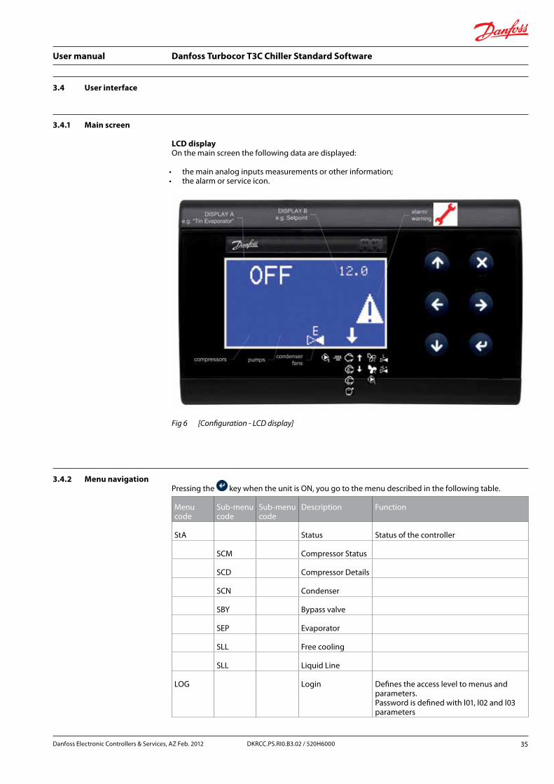
LCD displayOn the main screen the following data are displayed:
• the main analog inputs measurements or other information; • the alarm or service icon.
Fig 6 [Configuration - LCD display]
3.4.2 Menu navigation Pressing the key when the unit is ON, you go to the menu described in the following table.
Menu code
Sub-menu code
Sub-menu code
Description Function
StA Status Status of the controller
SCM Compressor Status
SCD Compressor Details
SCN Condenser
SBY Bypass valve
SEP Evaporator
SLL Free cooling
SLL Liquid Line
LOG Login Defines the access level to menus and parameters.Password is defined with l01, l02 and l03 parameters
Danfoss Electronic Controllers & Services, AZ Feb. 2012 35DKRCC.PS.RI0.B3.02 / 520H6000

User manual Danfoss Turbocor T3C Chiller Standard Software
Menu code
Sub-menu code
Sub-menu code
Description Function
PAR Parameters Access to menu of parameters. You need to login first
I/O Inputs/outputs Access to inputs/outputs menu
IOd I/O Display Display input and output values
ALA Alarms Access to alarm menu
AAL Active Alarms List of the active alarms
ALR Reset Alarms Alarms manual reset
SER Service Access to service information
INF Software info Information on application software
DEV Device info Information on device
DFP Reset to default Reset parameters to factory default
HCC Reset hour count Reset all hour counters (compr.,pumps,)
Tab 15 [Configuration - Menu navigation]
To navigate inside menus use the and keys. The key allows you to go down to the next
level, if present; the key allows you to go up to the previous level, up to the main screen.
To change the value of the selected parameters use the following keys:
• key, to enter in changing mode (the value starts to blink);
• and keys to change value;
• key again to confirm changes or key for not confirming them.
LoginMenu: LOG – LoginTo insert the 4 digit password defining the access level to menus and parameters. The current access level is then shown on the second raw of the main menu screen.
Press and keys to change the value of the selected digit.
Press key to confirm the value and skip to the next digit, if present, or to login.
The and keys, if present, allow you to move the cursor on the desired digit.
Password for the access levels from 1 to 3 are defined with l01 [1000], l02 [2000], l03 [3000] parameters, group1 “GEN - General”, group2 “pAS – Password”.
Without logging in, you get access level 0. You can’t see parameters or menu entries belonging to a higher level then yours. What is the level of each parameter and menu is defined with the configurator, (see 8.0 “Appendix – configurator usage”). If the inserted password is not correct you stays inside the login screen. Otherwise you get back to the main menu.
36 DKRCC.PS.RI0.B3.02 / 520H6000 Danfoss Electronic Controllers & Services, AZ Feb. 2012

User manual Danfoss Turbocor T3C Chiller Standard Software
ParametersMenu: PAR - ParametersGives access to parameters. For a description of each parameter menu. (See the relevant paragraph below).
Input and output displayMenu inputs/outputs – Inputs/outputs Sub-menu: IOd – inputs/outputs Display
LCD display
You have access to three screens showing all the input and output values; each screen shows a group
of 8 inputs/outputs. Use and keys to scroll them. The second and third screen are used with
MCX15 and MCX20 only. Below example shows the first screen.
Fig 7 [Configuration - Inputs/outputs LCD display]
Alarm display and configurationMenu: ALA – AlarmsSub-menu: AAL – Active Alarms. Shows you the active alarm screens. Each screen is dedicated to an alarm. You can scroll among them using the and keys.
Danfoss Electronic Controllers & Services, AZ Feb. 2012 37DKRCC.PS.RI0.B3.02 / 520H6000
User manual Danfoss Turbocor T3C Chiller Standard Software
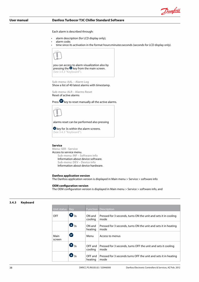
Each alarm is described through:
• alarm description (for LCD display only); • alarm code; • time since its activation in the format hours:minutes:seconds (seconds for LCD display only).
Note
you can access to alarm visualization also by pressing the key from the main screen. (See 3.4.3 “Keyboard”).
Sub-menu: AAL – Alarm LogShow a list of 40 latest alarms with timestamp.
Sub-menu: ALR – Alarms ResetReset of active alarms
Press key to reset manually all the active alarms.
Note
alarms reset can be performed also pressing
key for 3s within the alarm screens. (See 3.4.3 “Keyboard”).
ServiceMenu: SER - Service Access to service menu. Sub-menu: INF – Software info Information about device software. Sub-menu: DEV – Device info Information about device hardware.
Danfoss application versionThe Danfoss application version is displayed in Main menu > Service > software info
OEM configuration versionThe OEM configuration version is displayed in Main menu > Service > software info, and
3.4.3 Keyboard
Unit status Key Function Description
OFF 3s ON and cooling
Pressed for 3 seconds, turns ON the unit and sets it in cooling mode
3s ON and heating
Pressed for 3 seconds, turns ON the unit and sets it in heating mode
Main screen
Menu Access to menus
3s OFF and cooling
Pressed for 3 seconds, turns OFF the unit and sets it cooling mode
3s OFF and heating
Pressed for 3 seconds turns OFF the unit and sets it in heating mode
38 DKRCC.PS.RI0.B3.02 / 520H6000 Danfoss Electronic Controllers & Services, AZ Feb. 2012

User manual Danfoss Turbocor T3C Chiller Standard Software
Unit status Key Function Description
Alarms Admission to the list of active alarms
Menu Up Backward scroll of menu
Down Forward scroll of menu
--> Change to the next menu level, if present, or command execution
<-- Go back to the previous menu level, if present, or to the main screen
Login + Increment the selected digit
- Decrement the selected digit
OK Confirm the value and skip to the next digit, if present, or execute login.
<-- Go back to the previous menu level, if present, or to the main screen
Parameters navigation
Up Backward scroll of parameters or group of parameters
Down Forward scroll of parameters or group of parameters
--> Change to the next group of parameters, if present, otherwise enter in parameter programming mode, (see Prg)
<-- Go back to the previous menu level, if present, or to the main screen
Parameters changes
Prg/OK Enter in parameter programming modeConfirm the change
+ Increment the parameter value
- Decrement the parameter value
Esc Exit from programming mode discarding the change
Alarms list Up Backward scroll of the alarm list
Down Forward scroll of the alarm list
<--/Reset
Go back to the main screenPressed for 5 seconds, manual reset of all the active alarms
Power ON + 5s Default Pressed together for 5 seconds at power ON, force reloading the default values of all the parameters
Tab 16 [Configuration - Keyboard]
Change of the unit of measurementumt Temperature unit in display °C;°F ump Pressure unit in display bar;barg;psia;psig;kPa
Units on Modbus is °C and bar abs. (COM1 on MCX).
Danfoss Electronic Controllers & Services, AZ Feb. 2012 39DKRCC.PS.RI0.B3.02 / 520H6000

User manual Danfoss Turbocor T3C Chiller Standard Software
Accessing the BIOS menu (LCD display only)
By pressing simultaneously the and keys for 5 seconds (not on MCX06C and MCX06D), you
enter into a special BIOS menu; you can go through the voices of the menu using the and keys,
confirm your selection with the key or discard it with the key.
The menu is as follows:
• APPLICATION: to exit the bios menu and return to the application
• DISPLAY: to access the display setting menu
• CONTRAST: to set the LCD contrast; key =decrement, key =increment
• BRIGHTNESS: to set the LCD brightness; key =decrement, key =increment
• POS/NEG: to switch between positive and negative display using the key
• BUZZER: to set the buzzer volume and disable it; key =increment,
key =decrement
• CAN: to access the CAN communication configuration menu.
• NODE ID: to set the device address on the CAN network; key =increment,
key =decrement
• BAUDRATE: to set the device baud rate on the CAN network (from 10K to 1M)
3.5 “Main switch”The “Main Switch” is essential to start and stop the controller. When MainSwitch is OFF:
1. all outputs (analogue and digital) are set to zero or OFF;2. control functions are disabled;3. all MCX control alarms are disabled except “Main switch alarm” which is active. Other alarms can
be enabled when MainSwitch is off - can be defined by MCXShape.
Hardware input values are always updated. Serial communication via Modbus slave port (COM1 for BMS) and CAN are always possible. No communication to compressors (COM2) while Main Switch is off. “cms” is the short identification for “Main Switch” parameter.
External Main switchDigital input to be used is “ONO” “Main Switch”.
Conditions Signal inputs/outputs status menu
Ext. Main switch
DI7 - NO (Normally Open) 0 Vac 0 OFF.
DI7 - NO (Normally Open) 24 Vac 1 ON1)
DI7 - NC (Normally Closed) 0 Vac 1 ON2)
DI7 - NC (Normally Closed) 24 Vac 0 OFF.
1) If External Main switch is wanted for a closed contactor then chose NC2) If External Main switch is wanted for a open contactor then chose NO
Tab 17 [Configuration - Main switch]
40 DKRCC.PS.RI0.B3.02 / 520H6000 Danfoss Electronic Controllers & Services, AZ Feb. 2012
User manual Danfoss Turbocor T3C Chiller Standard Software
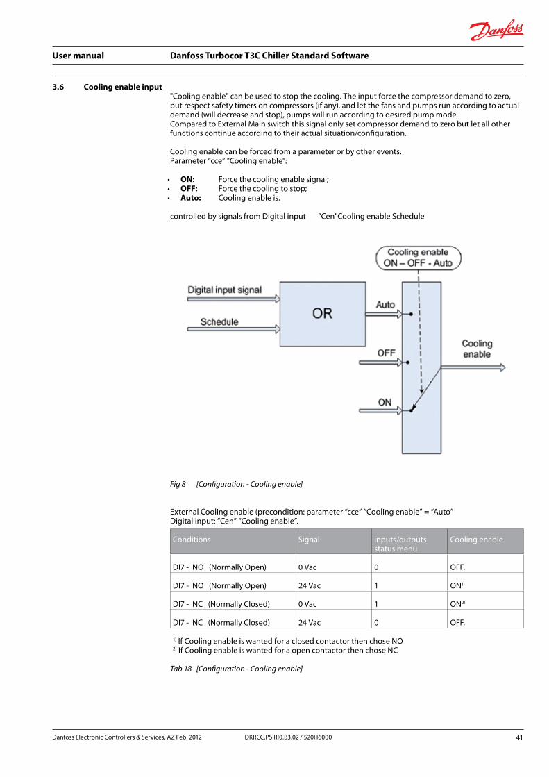
3.6 Cooling enable input"Cooling enable" can be used to stop the cooling. The input force the compressor demand to zero, but respect safety timers on compressors (if any), and let the fans and pumps run according to actual demand (will decrease and stop), pumps will run according to desired pump mode. Compared to External Main switch this signal only set compressor demand to zero but let all other functions continue according to their actual situation/configuration.
Cooling enable can be forced from a parameter or by other events. Parameter “cce” "Cooling enable":
• ON: Force the cooling enable signal; • OFF: Force the cooling to stop; • Auto: Cooling enable is.
controlled by signals from Digital input “Cen”Cooling enable Schedule
Fig 8 [Configuration - Cooling enable]
External Cooling enable (precondition: parameter “cce” “Cooling enable” = “Auto” Digital input: “Cen” “Cooling enable”.
Conditions Signal inputs/outputs status menu
Cooling enable
DI7 - NO (Normally Open) 0 Vac 0 OFF.
DI7 - NO (Normally Open) 24 Vac 1 ON1)
DI7 - NC (Normally Closed) 0 Vac 1 ON2)
DI7 - NC (Normally Closed) 24 Vac 0 OFF.
1) If Cooling enable is wanted for a closed contactor then chose NO2) If Cooling enable is wanted for a open contactor then chose NC
Tab 18 [Configuration - Cooling enable]
Danfoss Electronic Controllers & Services, AZ Feb. 2012 41DKRCC.PS.RI0.B3.02 / 520H6000
User manual Danfoss Turbocor T3C Chiller Standard Software
3.7 Interlock - inputs and outputs
Is a relay which must be connected to the interlock input of the Danfoss Turbocor compressor(s). When the signal is not available, the compressor will ramp down to 0 RPM and de-levitate. It is advisable to have the relay energized for normal operation (N.O.).
Interlock outputIf individual interlock relay outputs are defined, then individual Interlock relays will be activated if the individual compressor is reported as “offline”. (See 2.2 "Individual compressor states").
Example
“TC1 communication error” will then only activate the TC1 interlock relay and stop TC1 compressor.
Note
Evaporator Pump Water Flow Switch MUST be directly wired to the Danfoss Turbocor interlocks.
Interlock inputIt is essential to be able to stop the compressors in case of Modbus communication problems between the controller and the compressors. Therefore it is highly recommended to make interlock connections from MCX T3C to individual compressors.
It is possible to make individual interlock connections. The connection is made by relays and physical wires. The interlock relays are energized while every thing is OK.
Critical alarms, Interlock inputs, Main switch and communication problems will affect the interlock relays.
For interlock relays, following input and output must be configured. Digital input:
“TT0” TT Interlock common. • Digital input: “TT1” TT Interlock 1 • Digital input: “TT2” TT Interlock 2 • Digital input: “TT3” TT Interlock 3 • Digital input: “TT4” TT Interlock 4
One relay for each compressor: • digital output: “TT1” TT Interlock 1; • digital output: “TT2” TT Interlock 2; • digital output: “TT3” TT Interlock 3; • digital output: “TT4” TT Interlock 4.
Configure the parameters (default: enabled): • ”of1” ” Disable all compressors”; • ”of2” ” Disable compressor 1”; • ”of3” ” Disable compressor 2”; • ”of4” ” Disable compressor 3”; • ”of5” ” Disable compressor 4”.
42 DKRCC.PS.RI0.B3.02 / 520H6000 Danfoss Electronic Controllers & Services, AZ Feb. 2012

User manual Danfoss Turbocor T3C Chiller Standard Software
Main switch also affect the interlock relays for the compressors, whereas the Cooling enable don’t. (default behaviour defined by alarm “A01” “MainSwitch” in MCXShape).
By default these alarms are:
• “A01” “Main switch”; • “A02” “Refrigerant NOT selected: Select, Restart”; • “A03” “Evaporator flow switch alarm”; • “A05” “Communication fault”; • “A18” “LP 1 cutout alarm”; • “A20” “HP 1 cutout alarm”; • “A22” “Evaporator high flow rate alarm”; • “A92” “Evaporator low flow rate alarm”.
All alarms can be configured for activating interlock function from the Alarms tab in MCXShape (all configured compressors). But the mentioned alarms above should not be modified by user.
Interlock status is read from compressor, and a T3C alarm is made. The alarm text is: • A73 Common interlock activated; • A74 Compressor 1 interlock activated; • A75 Compressor 2 interlock activated; • A76 Compressor 3 interlock activated; • A77 Compressor 4 interlock activated; • A73 Common DI… input; • A74-A77 Status register from compressor.
Note
If interlock is taken directly on the Turbocor compressor (for service), then the corresponding compressor also must be set offline from MCX either by digital input or by parameter as described above.
3.8 Compressor controlCapacity control is based on a control signal and a reference. The capacity control depends also on actual situation like start-up and compressor availability. To handle that a state machine is used, (see 3.8 "Compressor control").
Danfoss Electronic Controllers & Services, AZ Feb. 2012 43DKRCC.PS.RI0.B3.02 / 520H6000
User manual Danfoss Turbocor T3C Chiller Standard Software
In case of sensor error on control sensor a substitution signal is calculated + an alarm is given:
• LWT control sensor Suction pressure + 5K; • EWT control sensor Suction pressure - 5K; • TC1 leaving condenser water Discharge pressure - 7K.
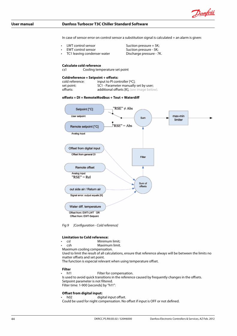
Calculate cold referencecs1 Cooling temperature set point
Coldreference = Setpoint + offsets:cold reference: input to PI controller [ºC]; set point: SC1 - Parameter manually set by user; offsets: additional offsets [K], (see image below).
offsets = DI + RemoteModbus + Tout + Waterdiff
Fig 9 [Configuration - Cold reference]
Limitation to Cold reference: • csl Minimum limit; • csh Maximum limit.Maximum cooling compensation. Used to limit the result of all calculations, ensure that reference always will be between the limits no matter offsets and set point. The function is especial relevant when using temperature offset.
Filter • h11 Filter for compensation.Is used to avoid quick transitions in the reference caused by frequently changes in the offsets. Setpoint parameter is not filtered. Filter time: 1-900 [seconds] by “h11”:
Offset from digital input: • h02 digital input offset.Could be used for night compensation. No offset if input is OFF or not defined.
44 DKRCC.PS.RI0.B3.02 / 520H6000 Danfoss Electronic Controllers & Services, AZ Feb. 2012
User manual Danfoss Turbocor T3C Chiller Standard Software
Remote set point offset (analog input):TREM Remote Set
Analogue external signal to make offset 0-10V or 0/4-20mA Range of offset is determined by defining the analogue input.
The analog input can be set to 3 modes:
• “RSE” “Remote set enable”: Ř NO Input ignored; Ř Abs Absolute setpoint from AI TrS "Remote Setpoint"
“cs1” “Cooling temperature set point” is over ruled, and analog input is used “RSL” and “RSH” to set the min and max scale. digital input ST3 "Remote Setpoint Enable" must be 1 in order to consider the remote offset;
Ř Rel Offset relative offset from AI Tr0 "Remote Offset"; digital input ST2 "Remote Offset Enable" must be 1 in order to consider the remote offset.
• “RSL” “Minimum limit” Value for minimum scale, e.g. 0.0 Volt: Ř replace analog input definition; Ř minimum absolute set point value (min probe range) used if RSE=1.
• “RSH” “Maximum limit” Value for maximum scale, e.g. 10.0 Volt: Ř replace analog input definition; Ř maximum absolute set point value (min probe range) used if RSE=1.
Note
Must be scaled in Degree Celsius.
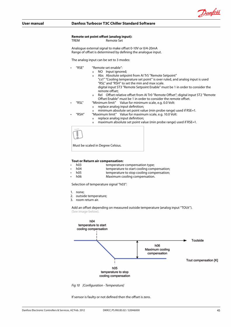
Tout or Return air compensation: • h03 temperature compensation type; • h04 temperature to start cooling compensation; • h05 temperature to stop cooling compensation; • h06 Maximum cooling compensation.
Selection of temperature signal “h03”:
1. none; 2. outside temperature;3. room return air.
Add an offset depending on measured outside temperature (analog input “TOUt”). (See image below).
Fig 10 [Configuration - Temperature]
If sensor is faulty or not defined then the offset is zero.
Danfoss Electronic Controllers & Services, AZ Feb. 2012 45DKRCC.PS.RI0.B3.02 / 520H6000

User manual Danfoss Turbocor T3C Chiller Standard Software
Water differential temperature compensationCompensatin is used a load compensation as water temperature difference is a measure for the load:
• h07 water diff. temp. offset compensation enable; • h08 offset to start cooling compensation; • h09 offset to stop cooling compensation; • h10 maximum offset compensation.
H07: • No no compensation; • Yes compensation is made according to description below.
Water differential temperature is calculated by: EWT-LWT.
But when the chiller stops, then the water temperatures for EWT and LWT will be equal meaning no offset. To obtain a reliable offset, the load compensation is changed to: EWT – Setpoint.
The offset is then scaled by function below
Fig 11 [Configuration - Offset]
If one off the sensors gets faulty then the offset is zero.
46 DKRCC.PS.RI0.B3.02 / 520H6000 Danfoss Electronic Controllers & Services, AZ Feb. 2012
User manual Danfoss Turbocor T3C Chiller Standard Software
3.8.1 Control of the cold side (PID)
A PID controller is used for the control of cold water. The controller divide the demand to individual Turboco compressors:
• cs2 integration time constant; • cs3 gain; • cs2 is set in seconds and is used for adapting to variation in plant time constant
(with a control error of 1K, the output will integrate 100% in “cs2” seconds); • cs3 proportional factor to amplify error signal;
(with a control error of 1K, the output will change “cs3” %).
Though the controller is preset during capacity shift (more/less compressors)
A PID controller has a Proportional gain part, a Integral part and a Derative part: • gain is the Proportional gain (Amplification factor); • integration time use unit [seconds]; • derative part if fixed in T3C.
When in a situation where you enlarge the P-band, you must lower the Kp (Amplification factor): • Kp=1: a step of 1K, means that 1K error (1K away from set point) will make an output
change of 1%; • Kp=10: a step of 1K, means that 1K error (1K away from set point) will make an output
change of 10%.
Comparison to the related term called P-band: • P-band = 1: a step of 1K, means that 1K error (1K away from set point) will make an output
change of 100%; • P-band = 10: a step of 10K, means that 10K error (10K away from set point) will make an
output change of 100%.
3.8.2 Compressor start/stop criterion (urgency zone)
Staging of compressors is always a compromise between:
• staging too often; • keeping set point.
The urgency zone control is used for identifying when a possible stage in/out of a compressor can be allowed. The urgency zone is an advance Neutral zone control. A neutral zone controller will not allow changes while in the neutral zone. Here it is a bit different.
Water temperature:
• far away from urgency zone stage in/out will be allowed after “cs4” “minimum urgency time”;
• slightly away from urgency zone stage in/out will be allowed after a longer time (React faster when the error increases);
• within urgency zone Delay staging for a long time or not stage at all (outmost 10% allow staging after very long time).
“cs4” "Low urgency zone width" min. 0,4 max. 5,0 default: 1,0 Kelvin Measured from set point
“cs5” "Minimum urgency time" min. 1 max. 9999 default: 60 seconds
Danfoss Electronic Controllers & Services, AZ Feb. 2012 47DKRCC.PS.RI0.B3.02 / 520H6000

User manual Danfoss Turbocor T3C Chiller Standard Software
Fig 12 [Configuration - Compressors]
Staging criteria’sStage in: • criteria from Urgency zone (from above) is full filled; • compressor at maximum:
Ř flag from compressor (“Maximum flow state” bit 10 in register 40029); Ř Relative speed above 97%; Ř power is above 97% of maximum compressor power.
Stage out: • criteria from Urgency zone (from above) is full filled; • compressor at minimum:
Ř flag from compressor (“Minimum IGV % reached” bit 11 in register 40029); Ř surge detected by MCX T3C, (see below #1); Ř minimum IGV (IGV at 70%); Ř demands to compressors are made by PID controller.
#1 • Minimum power defined by “t18” “Power stop” OR minimum IGV position by “t11” ”IGV stop“; • T3C surge detection algorithm enabled by parameter “t20”.
3.8.3 Hot gas bypass for start-up and load balancing
Plant efficiency is affected when used for filing out capacity gabs.
Stage inThe bypass valve will open as much as needed to guarantee that the pressure ratio drops below the threshold for staging in another compressor. Control point for start pressure ratio is defined by parameter “t16” “Maximum start pressure ratio”. Control slope at startup for the valve can be defined by “by3” ”Stagein state ramp rate” [permille per Sec.].
Load balanceAt low load for running compressors, the valve opens smoothly. The bypass valve will simply ramp open or shut at a preset rate. However, there is a maximum opening degree depending on the number of compressors that is currently running and the actual pressure ratio. This opening degree is designed to fill the triangular capacity gaps while it will not allow larger openings (you should stop a compressor to lower the capacity and not bypass more gas).
48 DKRCC.PS.RI0.B3.02 / 520H6000 Danfoss Electronic Controllers & Services, AZ Feb. 2012

User manual Danfoss Turbocor T3C Chiller Standard Software
Note
The maximum opening degree may be zero (at low pressure ratios where there is no capacity gap).
Control slope (while running [permille per Sec.]) for the valve can be defined by “by2” ” Capacity state ramp rate”.
Enabling of the valve is done by “by1” “Enable bypass valve”. Used analog output is: “VB1” “Bypass Valve 1”.
Fig 13 [Configuration - Hot gas]
Important, similar installation precautions as mentioned below must be made. Alternatively Hot gas bypass solenoid valves can be used, (see 3.8.4 "Hot gas bypass solenoid valves for start-up below").
3.8.4 Hot gas bypass solenoid valves for start-up
The bypass solenoids are used during startup of the compressors, and will open when the compressor is in “Starting” state and the speed is above a start speed of 5000 rpm (arbitrary value set as constant). Each compressor has two bypass solenoids which are opened at the same time. The first solenoid will close when the compressor exit the “Starting” state (and goes into “Operational” state). The second bypass solenoid will start a timer when the compressor is no longer in “Starting” state and will remain open until the timer has expired. (“t17” – “Bypass solenoid delay”). The result of this is that the bypass of gas is distributed (only two steps though), which should make the stage-in process more "gentle".
Danfoss Electronic Controllers & Services, AZ Feb. 2012 49DKRCC.PS.RI0.B3.02 / 520H6000

User manual Danfoss Turbocor T3C Chiller Standard Software
Note
If the chiller have only one compressor you should consider if it make sense to use special precautions for lowering pressure ratio by use of a hotgas bypass solenoid valve.
Considerations for piping
The design must avoid re-circulated hot gas in the suction line, because the heat effect will be (or can be) a dramatic heating up of the compressor. Hot gas injection must take place right after the expansion valve. Even with this design there can be unwanted heating effect. If the liquid line inlet is right below the suction inlet to the compressor then the hot gas is still hot!
To deal with this problem you must make a design where the liquid line into the barrel is miss-aligned from the suction line to the compressor and/or make other designs to cool the hot gas before it is directed into compressor suction pipe.
For design hints please (see image below), for more detailed information please contact Danfoss/Turbocor:
• the check valve of the compressor must be moved about 50 cm downstream of the discharge; • between the compressor's discharge port and the non return valve you must install a 4.5 cm
diameter pipe (the bypass); • the tube can be divided after the delivery, in two branches each with a solenoid; • it may still work just fine with 1 solenoid; • we do not recommend a bypass between the inlet and outlet because the compressor still works
and gas already moving from 20,000 rpm, and then we would have a loop already compressed gas directly in the inlet, where the speed of "over the surge was automatically calculated above 20,000;
• install a manual valve on the bypass pipe from the discharge outlet (to isolate the compressor).
The bypass can go out and conveyed by the two compressors on a common manifold.
Fig 14 [Configuration - Bypass]
50 DKRCC.PS.RI0.B3.02 / 520H6000 Danfoss Electronic Controllers & Services, AZ Feb. 2012

User manual Danfoss Turbocor T3C Chiller Standard Software
3.8.5 EconomizerThe Danfoss Turbocor centrifugal compressors have two impellers. The first-stage impeller raises the pressure of the refrigerant vapor approx. halfway from the suction pressure to the condenser pressure, and the second-stage impeller raises the pressure the rest of the way. With a two-stage compressor, an interstage economizer may be used to improve the refrigeration cycle efficiency.
A digital output for energizing a solenoid valve is present for individual compressors:
• when a compressor reach a relative speed > 85% and the compressor is in operational mode, then the economizer output is activated;
• when a compressor reach a relative speed1 < 50% or the compressor is not in operational mode, then the economizer output is de-activated.
Fig 15 [Configuration - Economizer principle diagram A]
Danfoss Electronic Controllers & Services, AZ Feb. 2012 51DKRCC.PS.RI0.B3.02 / 520H6000

User manual Danfoss Turbocor T3C Chiller Standard Software
MCX relay “Economizer enable” is engaged according to rules above, and Danfoss Turbocor compressor relay output on J3: “Compressor running” is used to activate individual running compressors. (See the example below - "Economizer principle diagram B - multiple compressors").
Outputs are EC1.
Fig 16 [Compressor control - Economizer principle diagram B - multiple compressors]
Can be enabled or disabled by “ec1” “Enable economizer”. Digital outputs for control of individual economizer control is selected by
Code Description
EC1 Economizer compressor 1
EC2 Economizer compressor 2
EC3 Economizer compressor 3
EC4 Economizer compressor 4
Tab 19 [Configuration - Economizer]
52 DKRCC.PS.RI0.B3.02 / 520H6000 Danfoss Electronic Controllers & Services, AZ Feb. 2012

User manual Danfoss Turbocor T3C Chiller Standard Software
3.8.6 Power signals for external monitoring (analog and digital)
Code Active power feedback
CF0 Minimum limit
CF1 Maximum limit
mca Minimum power capacity
DP0 Not used
DP1 Not used
Tab 20 [Configuration - Active power feedback]
CF0 – Maximum limitFor power feedback AO Apw "Active Power": this is the low power threshold (when power equals this value, AO will be 0V).
CF1 – Maximum limitFor power feedback AO Apw "Active Power": this is the high power threshold (when power equals this value, AO will be 10V).
mca – Minimum power capacityIf current chiller power is below this value, the relay “DO FA0” "Minimum active power status" will be activated.
DP0 – NOT USED
DP1 – NOT USED
Danfoss Electronic Controllers & Services, AZ Feb. 2012 53DKRCC.PS.RI0.B3.02 / 520H6000

User manual Danfoss Turbocor T3C Chiller Standard Software
3.9 Evaporator control
3.9.1 Liquid solenoide valve
The LLS valve open when first Danfoss Turbocor compressor is running. The valve close when no compressor capacity is running.
Used digital outputLS1 LLS circuit 1.
3.9.2 Level injection control
Regulation is on the low pressure side of the system. The valve will close on a rising liquid level.
Used analog inputLev1 Level control 1.
Used analog outputLEV1 Level Valve 1.
Code Name Description
cl1 Liquid level setpoint
Set point for control level
cl2 Man. - OFF - Auto
Manual, OFF or Automatic PID control
cl3 Manual valve 1 [%]
Manual opening degree if Le0=Man.
cl5 P-band P-band (regulating range around set point)The P-band (proportional band) is a regulating range set around the liquid levelSet point. The factory setting of 30% will give a regulating range that is 15% above and 15% below the actual liquid level set point, (see regulation example). 2). For ON-OFF control with a solenoid valve, this parameter must be set to 0% (OFF). If the P-band value is increased the regulation becomes slower
cl6 Integration time
Integration time TnDecreasing integration time will result in faster regulation (faster response to changes in sensor value). Thus a lower integration time will result in more fluctuation in valve opening percentage.If the Integration time is increased the regulation becomes slower
cl7 Neutral zone
Dead band or differential setting for ON-OFF control with solenoid valveEstablishing a dead band prevents excessive control action when liquid level percentage is close to the set point and oscillating above and below the set point.
lv1 Injection control type
- No;- Liquid level (AI: 0-100%);- Digital level (AI or DI - wet or dry);- Sub cooling ctrl.IMPORTANT NOTE:selection 2 and 3 are only for test, must be verified carefully if used, at current time a level sensor must always be available as backup solution!
lv2 OD minimum
Minimum opening degree
lv3 OD maximum
Maximum opening degree
54 DKRCC.PS.RI0.B3.02 / 520H6000 Danfoss Electronic Controllers & Services, AZ Feb. 2012

User manual Danfoss Turbocor T3C Chiller Standard Software
Code Name Description
lv4 High Level alarm
Set point for alarm “A39” “High Liquid Level 1”
lv5 Low Level alarm
Set point for alarm “A40” “Low Liquid Level 1”
lv6 Start opening degree
Opening % at initial start of the liquid injection
lv7 Regulation pressure side
Here you set whether the controller is to open or close the valve when the liquid level is risingLow (0): Regulation on the low-pressure side. The valve closes when liquid level is risingHigh (1): Regulation on the high-pressure side. The valve opens when liquid level is rising
le1 Liquid Subcooling Setpoint
Subcooling setpoint for subcooling injection type for liquid lineUsed together with “lv1” “Injection control type” = 3 (sub cooling ctrl)
le2 Liquid Subcooling min start OD time
Minimum time during which valve is kept at start OD (lv6) after compressor startup (0 means valve OD fixed only during compressor start)
Tab 21 [Configuration - Level injection control]
Danfoss Electronic Controllers & Services, AZ Feb. 2012 55DKRCC.PS.RI0.B3.02 / 520H6000

User manual Danfoss Turbocor T3C Chiller Standard Software
3.10 Evaporator water pump(s)
Water is the cooled fluid (”e02”=H2O), then we talk about evaporator water pump. In case of air (“e02”=air), we talk about evaporator fan, but this option is not supported with evaporator fan control.
The “Evap Pump1” digital output is used to drive the pump. When the number of pumps “e04” is equal to 2 (for water chiller only), also the “Evap Pump2” output is used to drive a second pump, (see 3.11 "Heaters"). For air units, on the contrary, “c03” must be set to 1 because software is able to manage only one evaporator fan.
The evaporator water pump functioning, here below described, is valid for the evaporator fan too.
According to “ce1” “Pump working mode” parameters these are the possible pump way of working:
• ce1=OFF. no regulation; • ce1=P1. pump 1 always used; • ce1=P2. pump 2 always used; • ce1=Rot pump 1 and Pump 2 are rotated according to pump working hours defined
by “e05” “Pump rotation working hours”.
Generally, the pump will be never switched OFF if all the compressors won’t first.
The pump will be switched OFF after a programmable delay e08 from the compressors switched OFF (with unit OFF).
Fig 17 [Configuration - Mode "Ce1"=ON]
Delay from pump on to compressor start is automatic given by urgency zone criteria timer.
e09 – Intermittent pulse ON time e10 – Intermittent pulse cycle time
When pumps have stopped, they can be forced on by frequent intervals defined by parameter “e09”. 0: means that they will never be turned on. The ON duration is controlled by “e10”.
For more parameters for pumps, (see 3.3.3 "Parameters for evaporator configuration").
56 DKRCC.PS.RI0.B3.02 / 520H6000 Danfoss Electronic Controllers & Services, AZ Feb. 2012

User manual Danfoss Turbocor T3C Chiller Standard Software
3.11 Heaters
3.11.1 Heaters in cooling mode: anti freeze control
ConfigurationAnti freeze control is active on those units where water is the chilled fluid and it is made on the outlet probe of the evaporator LWT1 (“Leaving chilled water 1”). It has the purpose to prevent evaporator icing:
“ch1” “Heater setpoint”; “ch2 "Heater differential”.
RegulationAnti freeze control consists in switching ON the anti freeze heaters on the affected evaporator, using the “Heater1”, ..., “Heater4” digital output, when the temperature measured by the probe on the evaporator output LWT1 goes below the configured limit as described in the following figure in case of 2 heaters.
Fig 18 [Configuration - Regulation]
In case of sensor error on LWT probe LWT1 is used. In case of both are in error then the performed control function is made as if the LWT temperature is below “ch1” – “ch2” (all heaters on).
Heater overloadDigital inputs can be configured for heater overload alarm inputs: OH1, .. OH4 (Heater1 Overload, .. Heater4 Overload): individual heater alarm.
In case of overload, the corresponding heaters are disengaged.
Ice alarmNo specific function is present, “Auxiliary alarms” can be configured for this purpose. (See 3.17 "Auxiliary input/output and alarms").
High temperature warningNo specific function is present, “Auxiliary alarms” can be configured for this purpose. (See 3.17 "Auxiliary input/output and alarms").
Danfoss Electronic Controllers & Services, AZ Feb. 2012 57DKRCC.PS.RI0.B3.02 / 520H6000

User manual Danfoss Turbocor T3C Chiller Standard Software
3.12 Condenser controlThe condenser is controlled according to discharge pressure converted to saturated temperature, either by local measured discharge pressure or the discharge pressure measured by the Danfoss Turbocor compressors. In case of an absent local discharge pressure, then signal is read from Danfoss Turbocor compressors (the highest pressure from any compressor in the circuit).
3.12.1 Condenser configuration
Code Condenser
c01 Number of condensers
c02 Air or water cooled condenser
c03 Number of pumps or fans per condenser
c04 Condenser ref. type
c05 Condenser Inverter enable
c06 Fan minimum speed
c07 Fan start speed
c08 Fan maximum speed
c09 Valve minimum opening degree
c10 Valve maximum opening degree
c11 Valve step change %
c13 Condenser Min_Tm
c14 Condenser Dim_Tm
c15 Condenser Min. reference
c16 Condenser Max. reference
c17 Nominal flow rate Qn
c18 Nominal pressuredrop PDn
c19 Minimum pressure drop PDmin
c20 Maximum pressure drop PDmax
c21 Forced fans temperature probe
c22 Minimum cond temp to force fans at full
c23 demand for Fan at zero speed” = 30% (interpolated point)
c24 demand for Valve at max OD” = 30%
Tab 22 [Configuration - Condenser configuration]
58 DKRCC.PS.RI0.B3.02 / 520H6000 Danfoss Electronic Controllers & Services, AZ Feb. 2012

User manual Danfoss Turbocor T3C Chiller Standard Software
In the air cooled units (c02=Air), the condensing regulation .is achieved by managing the condenser battery fans. In the water cooled units (c02=H2O), the condensing regulation is achieved by managing of the water pump on the condensing circuit. In both cases the sensor used for regulation must be configured (local discharge pressure transmitter or pressure signal from Danfoss Turbocor compressor.
c01 – Number of condensersDefines the number of condensers (currently always one)
c02 – Air or water cooled condenserAir cooled“Air”: The cooling is made by a number of fans controlled by steps or speed controlled by external variable speed controller.
Note
Step controlled fans will make pressure transients when staging fans and make the life difficult for the compressors.
Water cooled“H2O”: The capacity controller controls a water cooled condenser by means of a 3-way valve and step/speed control of dry cooler fans.
c03 – Number of fans per condenserTotally up to 8 fans are supported
c04 – Condenser ref. typeCondenser reference can be defined to operate in different modes:
1. fixed reference defined by a defined by “cc1” “Condenser set point” + External offset (external offset is default 0 Kelvin - independent of missing external setup);
2. fixed reference defined by “cc1” “Condenser set point” + offset from Suction capacity control;3. floating reference according to condenser ambient temperature.
For more details (see 3.12.2 "Condenser reference").
c05 – Condenser Inverter enableDefines if an inverter is applied.
c06 – Fan minimum speedMinimum speed for variable speed controlled fans.
c07 – Fan start speedSpeed to start first fan – is useful for phase cutting controls.
c08 – Fan maximum speedMaximum speed for variable speed controlled fans.
c09 – Valve minimum opening degreeMinimum opening degree for Valve (“Valve Cond1”) used in water cooled applications.
c10 – Valve maximum opening degreeMaximum opening degree for Valve (“Valve Cond1”) used in water cooled applications.
c11 – Valve step change %Used to avoid frequent update on a stepper motor controlled valve. As an example a set point of 5% will have the effect that new required value must change more than +/- 5% from current value before a changed value is updated on the analog output.
c13 – Condenser Min_TmMinimum temperature across the condenser at zero load (minimum load). (See 3.12.2 "Condenser reference").
Danfoss Electronic Controllers & Services, AZ Feb. 2012 59DKRCC.PS.RI0.B3.02 / 520H6000

User manual Danfoss Turbocor T3C Chiller Standard Software
c14 – Condenser Dim_Tm
The condenser’s dimensioned temperature difference between the air temperature and the condensing temperature at 100% compressor capacity (dim_tm [K]). (See 3.12.2 "Condenser reference").
c15 – Condenser Min referenceMinimum saturated condensing temperature. (See 3.12.2 "Condenser reference").
c16 – Condenser Max referenceMaximum saturated condensing temperature. (See 3.12.2 "Condenser reference").
c17 – Nominal flow rate QnNominal flowrate at nominal differential pressure defined by “c18” “Nominal pressuredrop PDn”. Differential pressure is measured using two analog inputs “WIC” “Inlet Water Pressure Condenser” and “WOC” “Outlet Water Pressure Condenser”.
c18 – Nominal pressuredrop PDnUsed to define Nominal flowrate. (See "parameter c17 above").
c19 – C Minimum pressure drop PDminAlarm level for alarm “A92” “Condenser low flow rate alarm”.
c20 – C Maximum pressure drop PDmaxAlarm level for alarm “A91” “Condenser high flow rate alarm”.
c21 – Forced fans temperature probeThe probe used to compare temperature with “c22” value: 0 means no forcing, 1 is condenser temperature, 2 is outside air temperature.
c22 – Minimum cond temp to force fans at fullDuring compressor start-up procedure: If chosen temperature “c21” is above this value, condenser fans are forced to full speed.
c23 - demand for Fan at zero speedPoint up to where the PID demand make the fans have an speed of zero. Because the minimum speed and start speed overrules "c23". This parameter is in any case the interpolated demand for Fan at zero speed.
c24 - demand for Valve at max ODPoint where the PID demand make the valve have maximum opening degree (as defined by "c10" Valve max. OD).
60 DKRCC.PS.RI0.B3.02 / 520H6000 Danfoss Electronic Controllers & Services, AZ Feb. 2012
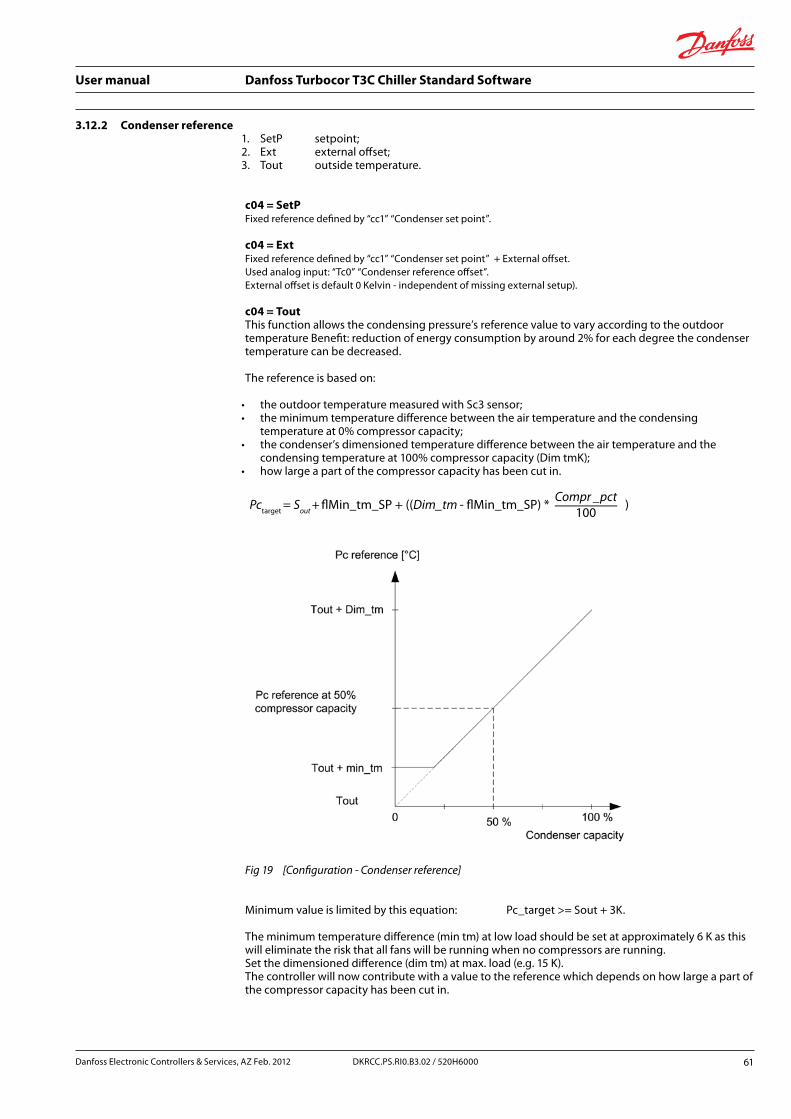
User manual Danfoss Turbocor T3C Chiller Standard Software
3.12.2 Condenser reference1. SetP setpoint;2. Ext external offset;3. Tout outside temperature.
c04 = SetPFixed reference defined by “cc1” “Condenser set point”.
c04 = ExtFixed reference defined by “cc1” “Condenser set point” + External offset.Used analog input: “Tc0” “Condenser reference offset”.External offset is default 0 Kelvin - independent of missing external setup).
c04 = ToutThis function allows the condensing pressure’s reference value to vary according to the outdoor temperature Benefit: reduction of energy consumption by around 2% for each degree the condenser temperature can be decreased.
The reference is based on:
• the outdoor temperature measured with Sc3 sensor; • the minimum temperature difference between the air temperature and the condensing
temperature at 0% compressor capacity; • the condenser’s dimensioned temperature difference between the air temperature and the
condensing temperature at 100% compressor capacity (Dim tmK); • how large a part of the compressor capacity has been cut in.
Pctarget = Sout + �Min_tm_SP + ((Dim_tm - �Min_tm_SP) *-Compr _pct
100)
Fig 19 [Configuration - Condenser reference]
Minimum value is limited by this equation: Pc_target >= Sout + 3K.
The minimum temperature difference (min tm) at low load should be set at approximately 6 K as this will eliminate the risk that all fans will be running when no compressors are running. Set the dimensioned difference (dim tm) at max. load (e.g. 15 K). The controller will now contribute with a value to the reference which depends on how large a part of the compressor capacity has been cut in.
Danfoss Electronic Controllers & Services, AZ Feb. 2012 61DKRCC.PS.RI0.B3.02 / 520H6000

User manual Danfoss Turbocor T3C Chiller Standard Software
For any mode the resulting Pctarget is always limited by Pcref.max and Pcref.min:This applies to any offset compensation or above reference mode.
• sout outdoor temperature filtered with a fixed time constant of 5 minutes; • sout_err signal status 0:OK 1: error; • compr_pct is the filtered value of total compressor capacity in %
(filter time constant 20 Sec. - In actual software version this value is constant 100%;
• min_tm minimum temperature across the condenser at zero load (minimum load); • dim_tm actual dimensioned load temperature across the condenser at full load; • pcmin minimum saturated condensing temperature; • pcmax maximum saturated condensing temperature.
Limitations: • If Min_tm > Max_tm Min_tm = Max_tm; • if Pcmin > Pcmax Pcmin = Pcmax; • if Sout sensor fails: Pc_target = “cc1” “Condenser setpoint”.
3.12.3 Parameters for condenser control
Code Condenser
cc1 Condenser set point
cc2 Man.- OFF – Auto for Fan
cc3 Man. % Fan
cc4 Man.- OFF – Auto for Valve
cc5 Man. % Valve
cc6 Kp condenser
cc7 Tn condenser
Tab 23 [Configuration - Parameters for condenser control]
cc1 – Condenser set pointSet point for reference calculation as described above.
cc2 – Man. – OFF – Auto for FanMan. condenser Fan capacity is preset to a fixed value defined by “cc3”. Very useful for commissioning.
OFF condenser Fan capacity is preset to 0% (stopped)Auto condenser Fan capacity is controlled by PID according to calculated reference above.
cc3 – Man. % FanWhen cc2 is in “Man.” then condenser fan capacity is defined by this parameter.
cc4 – Man. – OFF – Auto for ValveMan condenser Valve capacity is preset to a fixed value defined by “cc5”. Very useful for commissioning. OFF condenser Valve capacity is preset to 0% (stopped). Auto condenser Valve capacity is controlled by PID according to calculated reference above.
cc5 – Man. % ValveWhen cc4 is in “Man.” then condenser Valve capacity is defined by this parameter.
cc6 – Kp condenserProportional gain factor for PID controller (If the Kp value is reduced the regulation becomes slower)
62 DKRCC.PS.RI0.B3.02 / 520H6000 Danfoss Electronic Controllers & Services, AZ Feb. 2012
User manual Danfoss Turbocor T3C Chiller Standard Software
cc7 – Tn condenser
Integration time for PID controller. (If the Tn value is increased the regulation becomes slower).
A PID controller has a Proportional gain part, a Integral part and a Derative part: Kp is the Proportional gain; Tn is the integral time [seconds]; Derative part if fixed in T3C.
When in a situation where you enlarge the P-band, you must lower the Kp (gain):
• Kp = 1: a step of 1K, means that 1K error (1K away from set point) will make an output change of 1%;
• Kp = 10: a step of 1K, means that 1K error (1K away from set point) will make an output change of 10%.
Comparison to the related term called P-band: • P-band = 1: a step of 1K, means that 1K error (1K away from set point) will make an
output change of 100%; • P-band = 10: a step of 10K, means that 1K error (1K away from set point) will make an
output change of 100%; • Tn = 180: a step of 1K, means that 1K error (1K away from set point) will make a linear
output change of 100% within 180 seconds.
Danfoss Electronic Controllers & Services, AZ Feb. 2012 63DKRCC.PS.RI0.B3.02 / 520H6000

User manual Danfoss Turbocor T3C Chiller Standard Software
3.12.4 Air condensing unitIn the air cooled units, the number of fans (or more precisely the number of steps, as fans could be grouped together in parallel) for each battery must be set in “c03”.
The digital output used for condensing step control are “Condenser Fan1”, “Condenser Fan2”, “Condenser Fan3”, ..., Condenser Fan8”.
The output used to drive possible inverter is the digital output “Inverter Cond1” (start signal) and analog signal “InverterFanCond1“. Following set points apply for inverter controlled fans, (see 3.12.1 "Condenser configuration").
Code Condenser
c06 Fan minimum speed
c07 Fan start speed
c08 Fan maximum speed
Tab 24 [Configuration - Air condensing unit]
Way of workingGroup2: cS1 – ConfigurationAccording to “c01” parameters these are the possible ways for condensing regulation:
• “c01”=0. No regulation; • “c01”=1. condenser control for individual setup circuits.
3.12.5 Step regulation in cooling
Fans are driven in ON/OFF, depending on cc1 set point and on PID settings Kp and Tn (cc6:gain and cc7:integration time):
• Kp: output demand% for a control error equal to one °C (proportional gain) (If the Kp value is decreased the regulation becomes slower);
• Tn: output demand% for a control error of one °C after Tn seconds (integration time) (If the Integration time is increased the regulation becomes slower).
64 DKRCC.PS.RI0.B3.02 / 520H6000 Danfoss Electronic Controllers & Services, AZ Feb. 2012
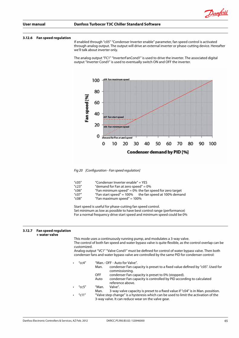
User manual Danfoss Turbocor T3C Chiller Standard Software
3.12.6 Fan speed regulationIf enabled through “c05” “Condenser Inverter enable” parameter, fan speed control is activated through analog output. The output will drive an external inverter or phase-cutting device. Hereafter we’ll talk about inverter only.
The analog output “FC1” “InverterFanCond1” is used to drive the inverter. The associated digital output “Inverter Cond1” is used to eventually switch ON and OFF the inverter.
Fig 20 [Configuration - Fan speed regulation]
”c05” “Condenser Inverter enable” = YES ”c23” ”demand for Fan at zero speed” = 0% “c06” “Fan minimum speed” = 0% the fan speed for zero target “c07” “Fan start speed” = 100% the fan speed at 100% demand “c08” “Fan maximum speed” = 100%
Start speed is useful for phase-cutting fan speed control. Set minimum as low as possible to have best control range (performance) For a normal frequency drive start speed and minimum speed could be 0%
3.12.7 Fan speed regulation + water valve
This mode uses a continuously running pump, and modulates a 3-way valve. The control of both fan speed and water bypass valve is quite flexible, as the control overlap can be customized. Analog output “VC1” “Valve Cond1” must be defined for control of water bypass valve. Then both condenser fans and water bypass valve are controlled by the same PID for condenser control:
• “cc4” “Man.- OFF - Auto for Valve”. Man. condenser Fan capacity is preset to a fixed value defined by “c05”. Used for commissioning. OFF condenser Fan capacity is preset to 0% (stopped). Auto condenser Fan capacity is controlled by PID according to calculated reference above.
• “cc5” “Man. Valve”. Man. 3-way valve capacity is preset to a fixed value if “c04” is in Man. possition.
• “c11” “Valve step change” is a hysteresis which can be used to limit the activation of the 3-way valve. It can reduce wear on the valve gear.
Danfoss Electronic Controllers & Services, AZ Feb. 2012 65DKRCC.PS.RI0.B3.02 / 520H6000

User manual Danfoss Turbocor T3C Chiller Standard Software
Precondition for the control is that water valve always starts from zero demand until a user defined demand for maximum opening degree. Precondition for the control is that fans starts from a user defined zero speed and until a 100% condenser demand.
The Water bypass valve will start from 0% demand, having the minimum demand as specified by “c09” “Valve min. OD”, and “c10” “Valve max. OD”. The Condenser demand by PID for maximum Valve opening degree, can be adjusted by “demand for Valve at max OD”
Fig 21 [Configuration - Water valve]
• ”c05” “Condenser Inverter enable” = YES. • ”c24” ”demand for Valve at max OD” = 30%. • ”c23” ”demand for Fan at zero speed” = 0% (interpolated point). • “c06” “Fan minimum speed” = 20%. • “c07” “Fan start speed” = 30%. • “c08” “Fan maximum speed” = 100%. • “c09” “Valve min. OD” = 30%. • “c10” “Valve max. OD” = 100%.
The example above could make use of a fan speed control where a certain start speed is needed for start.
The fans starts when the valve is fully open, and valve stay at max while the fans increase capacity. When going down in needed condenser capacity the fans are running until demand is zero – the valve stay at minimum.
66 DKRCC.PS.RI0.B3.02 / 520H6000 Danfoss Electronic Controllers & Services, AZ Feb. 2012

User manual Danfoss Turbocor T3C Chiller Standard Software
Fig 22 [Configuration - Water tower]
• ”c05” “Condenser Inverter enable” = YES. • ”c24” ”demand for Valve at max OD” = 30%. • ”c23” ”demand for Fan at zero speed” = 30% (interpolated point). • “c06” “Fan minimum speed” = 0% the fan speed for zero target. • “c07” “Fan start speed” = 25% the fan speed at 100% demand. • “c08” “Fan maximum speed” = 100%. • “c09” “Valve min. OD” = 35%. • “c10” “Valve max. OD” = 100%.
The example above could make use of a fan speed control where no start speed is needed, or as here configure for 10% to have some start hysteresis.
The fans starts 7-8% after valve is fully open, and valve stay at max while the fans increase capacity. When going down in needed condenser capacity the fans are stopped at 25% demand where the valve is still full open. On the low 25% condenser demand the control is only maintained by the valve.
3.13 Condenser pumpThe condenser pump can be configured by setting up relay output “PC1” “Condenser Pump 1”. Condenser pump overload is controlled by digital input “PC1” “Cond Pump Overld”. The generated alarm is “A12” “Condenser pump overload alarm”. If the input is configured and the input is ON then the input will stop the pump.
Parameters “e08” are reused from evaporator pump configuration.
e08 – Pump OFF delayTime to let pump run after last compressor has stopped.
Cc8 – Pump working modeOFF or P1
Danfoss Electronic Controllers & Services, AZ Feb. 2012 67DKRCC.PS.RI0.B3.02 / 520H6000
User manual Danfoss Turbocor T3C Chiller Standard Software
Cc9 – Pump ON conditionFor service purposes the user must be able to select the actual pump control mode:
1. “MS”, Start when “Main Switch” is on.2. “CE“ Start when “Chiller enable” input is active.3. “Comp” Start with first compressor (when demand is bigger than zero%).
Note
analog signal for 3-way valve output can also be used for speed control of condenser pumps.
3.14 Adiabatic/evaporative condenser controls
Adiabatic condenser cooling is the process of spraying water into the air supply of an air cooled condenser or dry cooler to pre cool the air and improve refrigeration efficiency.
This function is used to control an evaporative condenser pump and a heater for frost protection. The evaporative condenser pump can be controlled by:
• Ct1 adiabatic condenser control: Ř 0:Pump Pump is constant ON; Ř 1:Heat Heat is constant ON; Ř 2:OFF Both off; Ř 3:Auto Pump and heater controlled according to demand.
• Ct2 adiabatic pump setpoint, setpoint to start the pump;
• Ct3 adiabatic pump differential, differential below set point to stop the pump;
• Ct4 adiabatic heater setpoint, setpoint to start heating element;
• Ct5 adiabatic heater differential, differential below set point to stop heating element.
Adiabatic pump has a restart protection for minimum 15 seconds. Adiabatic pump is controlled by saturated condensing temperature (pressure converted to temperature). Adiabatic heater is controlled by out side air temperature by input “Tou” “Toutside”, A missing Toutside temperature sensor will generate a sensor alarm and engage the heater.
68 DKRCC.PS.RI0.B3.02 / 520H6000 Danfoss Electronic Controllers & Services, AZ Feb. 2012

User manual Danfoss Turbocor T3C Chiller Standard Software
3.15 Water free-cooling
OverviewGroup1: CFG – Unit ConfigGroup2: fRC – Free coolingThe free-cooling regulation uses the favorable conditions of outside air temperature to contribute to the cooling water. It uses an additional coil (free-cooling coil) in which, through the free-cooling valve is deflected a certain amount of water returning from the plant if the outside air temperature conditions are favorable.
The free-cooling coil is located inside the machine upstream of the condensing coil, and with that share control of condensing fans. The free-cooling management is active only in air / water units in cooling mode.
Note
In case of multiple evaporators and condensers, the free-cooling is handled only on the first evaporator and condenser.
Fig 23 [Configuration - Water free-cooling]
Danfoss Electronic Controllers & Services, AZ Feb. 2012 69DKRCC.PS.RI0.B3.02 / 520H6000

User manual Danfoss Turbocor T3C Chiller Standard Software
3.15.1 Used parameters
Code Free-cooling
fr0 Enable free cooling
fr2 Free cooling activation delta
fr4 Valve offset
fr5 Valve differential
fr6 Fan offset
fr7 Fan differential
fr8 Freeze alarm
fr9 Valve step change %
Tab 25 [Configuration - Free-cooling]
ActivationThe conditions of free cooling activation are:
• the free-cooling is enabled (parameter Fr0 other than NO) and the unit is an air/water machine in cooling mode;
• the water circulating pump is operating; • the following condition which certifies the convenience of free-cooling is verified:
FR1 – Tout > = “Fr2”; • are not verified alarm conditions, (see the following paragraph).
DeactivationThe conditions of free cooling deactivation are: • the free-cooling is disabled (parameter Fr0 = NO), or the unit is not an air/water machine, or it is in
heating mode; • the water circulating pump is not operating; • the free-cooling condition is no more active:
TFC1 – Tout < Fr2 – 1,5°C; • anti freeze heaters are active; • any of the following alarm conditions occurred:
Ř antifreeze alarm; Ř serious alarm from digital input; Ř pump overload alarm; Ř evaporator flow alarm; Ř fault of regulation probe; Ř anti freeze probe; Ř free-cooling probe; Ř outside temperature probe.
70 DKRCC.PS.RI0.B3.02 / 520H6000 Danfoss Electronic Controllers & Services, AZ Feb. 2012
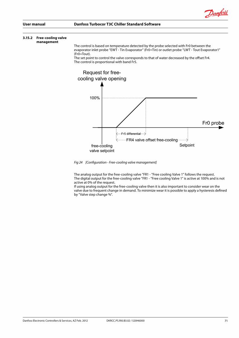
User manual Danfoss Turbocor T3C Chiller Standard Software
3.15.2 Free-cooling valve management
The control is based on temperature detected by the probe selected with Fr0 between the evaporator inlet probe “EWT - Tin Evaporator” (Fr0=Tin) or outlet probe “LWT - Tout Evaporator1” (Fr0=Tout). The set point to control the valve corresponds to that of water decreased by the offset Fr4. The control is proportional with band Fr5.
Fig 24 [Configuration - Free-cooling valve management]
The analog output for the free-cooling valve “FR1 - “Free cooling Valve 1” follows the request. The digital output for the free-cooling valve “FR1 - “Free cooling Valve 1” is active at 100% and is not active at 0% of the request. If using analog output for the free-cooling valve then it is also important to consider wear on the valve due to frequent change in demand. To minimize wear it is possible to apply a hysteresis defined by “Valve step change %”.
Danfoss Electronic Controllers & Services, AZ Feb. 2012 71DKRCC.PS.RI0.B3.02 / 520H6000

User manual Danfoss Turbocor T3C Chiller Standard Software
3.15.3 Fan management in free-cooling
The fans are shared between the control of free-cooling and condensation. In the event of start of one or more compressors the priority is given to condensation control. When there is not demand for condensation control (compressor off), the control of free-cooling fans is based on temperature detected by the probe selected with Fr0 between the evaporator inlet probe “TIN - Tin Evaporator” (Fr0=Tin) or outlet probe “LWT - Tout Evaporator1” (Fr0=Tout). The set point to control the fans corresponds to that of water decreased by the offset Fr6. The control is proportional with band Fr7.
Fig 25 [Configuration - Fan management in free-cooling]
The analog output for the fan on the first condenser “Fc1 - “InverterFanCond1”, follows the request if enabled by F10 = YES. Fan steps “FC1, ..., FC8” share equally the control band Fr7.
Anti freeze of the free-cooling coilWe define an antifreeze threshold based on the value of outside air temperature for the free-cooling coil protection. If the outside air temperature “Tout” is below the threshold of antifreeze “fr8”, the main circulation pump is turned on and the free-cooling valve is operated as follows
If the valve is of type 0-10V:
• with "cooling enable" OFF it is open at 100% of its capacity; • with "cooling enable" ON it is open at 10% of its capacity.
If the valve is of type ON/OFF opening is always at 100%. The procedure stops with a fixed hysteresis of 1K.
Note
Anti freeze of the free-cooling coil is active only if unit is ON (Main Switch is ON).
72 DKRCC.PS.RI0.B3.02 / 520H6000 Danfoss Electronic Controllers & Services, AZ Feb. 2012

User manual Danfoss Turbocor T3C Chiller Standard Software
3.16 Heat recoveryHeat recovery function can be used to switch condenser heat from one condenser cooler to another, like from fan cooled condenser to a water heat exchanger.
Function is not implemented.
3.16.1 Load limit – compressor power limitation
Load limitation could be needed in connection with startup of a power generator.
Some installations have need load shedding in order to limit the energy consumption in the building at power peak load times. A convenient way to temporarily limit power consumption is to make load shedding to the Turbocor water chiller. Limitation is available via digital inputs, via analogue input or via a parameter. The controller will set the current limit to the most restrictive of the following options:
For any of above inputs.When one of the limit functions is below 100%, then a warning is made (“Capacity limited”) The limit percentage is related to “t09” “Rated power consumption”.
Note
System cooling capacity does not have a linear relation to power consumption when dealing with Turbocor compressors.
Capacity limitation is only active during capacity state “operational”.
There are methods to make power limitation in T3C. The controller set the power limit to the most restrictive of the following options:
1. by a parameter “t07” – “Load shedding percentage” to set the maximum power limit, the parameter is stored in non-volatile memory. This option is for long term solutions;
2. a digital input “External load shedding” can set maximum load%. can set maximum power defined by parameter "max current limit". The definition of the maximum current is set by parameter "Max Current Limit (DI)";
3. an analogue input “External load shedding” can set maximum load%. The definition of the maximum load is defined by the analog input. Could be 0-10V for 0,0% – 100,0% or 0-10V for 100.0%-0,0%.
Note
Error for the defined analog input must be disabled.
Danfoss Electronic Controllers & Services, AZ Feb. 2012 73DKRCC.PS.RI0.B3.02 / 520H6000
User manual Danfoss Turbocor T3C Chiller Standard Software
Limitation via digital input:When activating a "Load limit" digital input, then the limit function must limit to a preset value, default is 100% (no limit):
• "Load limit %"; • range 0-100%; • default 100%.
Limitation via Analogue input.Analogue input must be setup to one of following types. 0-1V, 0-5V, 0-10V, 0-20mA or 4-20mA:
• for all inputs the range 0-100%; • for signals below the range the Limit value is limited to 0%; • for signals above the range the Limit value is limited to 100%.
74 DKRCC.PS.RI0.B3.02 / 520H6000 Danfoss Electronic Controllers & Services, AZ Feb. 2012
User manual Danfoss Turbocor T3C Chiller Standard Software
3.16.2 High load but low pressure ratio
The special compressor map for Danfoss Turbocor compressors indicate that maximum capacity is delivered when pressure ration is between 3.5 and 4.0 (TT300). For other types it is different. Maximum power is required in plant start-up situations. Here it can be required to increase the condenser reference to achieve maximum power (increase the pressure ratio). The controller handle this situation by adding an increasing offset with a fixed slope of 1K/minute until condenser reference is as defined by “t06” “Minimum pressure ratio at maximum load”. This offset start increasing when all compressors are at maximum power and pressure ratio is below “t06”. Otherwise the offset is decreased until zero offset from this function. The offset will be limited by normal min/max limitation of the condenser reference. (See 3.12.2 "Condenser reference"). The offset value is set to zero if “Main Switch” is set to OFF.
Note
Default value for “t06” is 2.0 which are same as function is not active. The “t06” pressure ratio value must be adapted to current Danfoss Turbocor compressor type.
The function can be disabled
“t19” “High Load Low Capacity ctrl enable”:
• OFF function disabled; • ON function enabled.
Danfoss Electronic Controllers & Services, AZ Feb. 2012 75DKRCC.PS.RI0.B3.02 / 520H6000

User manual Danfoss Turbocor T3C Chiller Standard Software
3.17 Auxiliary inputs/ outputs and alarms
Auxiliary digital inputs and auxiliary analogue inputs can be assigned. They can be used to activate alarms and relays. Text descriptions and alarm texts can be customized.
3.17.1 Auxiliary digital inputs
Digital auxiliary inputs can set an alarm and control a relay based on the alarm condition. This means that the alarm can be delayed as specified in setup for individual alarms. Auxiliary alarm relay is activated after alarm delays has expired. The alarm can affect the alarm relays and alarm. (See 4.0 “Alarms”). Up to 10 Digital auxiliary alarm inputs with corresponding alarm relay can be defined.
Following steps are required to setup an alarm input:
1. define a digital input (‘General alarm 1’ to ‘General alarm 10’), define polarity for the input. Input name can be modified. (MCXShape sheet ‘Digital_input’);
2. define the appropriate alarm definitions for ‘General DI alarm 1’ to ‘General DI alarm 10’ (Excel sheet ‘Alarm’) – alarm texts can be modified;
3. optional: Define an alarm relay output ‘General DI alarm 1’ to ‘General DI alarm 10’. Define corresponding polarity for the relay. (Excel sheet ‘Digital_output’);
4. parameters to define alarm actions.
Code Auxiliary inp. 1-10
d01 DI auxiliary 1 alarm action
d02 DI auxiliary 2 alarm action
d03 DI auxiliary 3 alarm action
d04 DI auxiliary 4 alarm action
d05 DI auxiliary 5 alarm action
d06 DI auxiliary 6 alarm action
d07 DI auxiliary 7 alarm action
d08 DI auxiliary 8 alarm action
d09 DI auxiliary 9 alarm action
d10 DI auxiliary 10 alarm action
Tab 26 [Configuration - Digital inputs]
Values:
1. auxiliary alarm;2. stop compressor 1;3. stop compressor 2;4. stop compressor 3;5. stop compressor 4;6. stop compressor 1 to 4 (circuit A);7. stop compressor 5 to 8 (circuit B) not supported;8. stop compressors (all).
76 DKRCC.PS.RI0.B3.02 / 520H6000 Danfoss Electronic Controllers & Services, AZ Feb. 2012
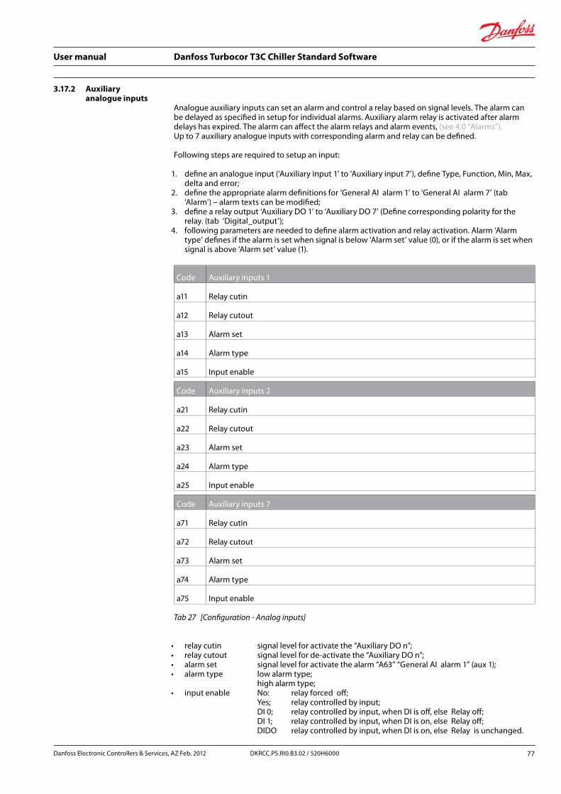
User manual Danfoss Turbocor T3C Chiller Standard Software
3.17.2 Auxiliary analogue inputs
Analogue auxiliary inputs can set an alarm and control a relay based on signal levels. The alarm can be delayed as specified in setup for individual alarms. Auxiliary alarm relay is activated after alarm delays has expired. The alarm can affect the alarm relays and alarm events, (see 4.0 “Alarms”). Up to 7 auxiliary analogue inputs with corresponding alarm and relay can be defined.
Following steps are required to setup an input:
1. define an analogue input (‘Auxiliary input 1’ to ‘Auxiliary input 7’), define Type, Function, Min, Max, delta and error;
2. define the appropriate alarm definitions for ‘General AI alarm 1’ to ‘General AI alarm 7’ (tab ‘Alarm’) – alarm texts can be modified;
3. define a relay output ‘Auxiliary DO 1’ to ‘Auxiliary DO 7’ (Define corresponding polarity for the relay. (tab ‘Digital_output’);
4. following parameters are needed to define alarm activation and relay activation. Alarm ‘Alarm type’ defines if the alarm is set when signal is below ‘Alarm set’ value (0), or if the alarm is set when signal is above ‘Alarm set’ value (1).
Code Auxiliary inputs 1
a11 Relay cutin
a12 Relay cutout
a13 Alarm set
a14 Alarm type
a15 Input enable
Code Auxiliary inputs 2
a21 Relay cutin
a22 Relay cutout
a23 Alarm set
a24 Alarm type
a25 Input enable
Code Auxiliary inputs 7
a71 Relay cutin
a72 Relay cutout
a73 Alarm set
a74 Alarm type
a75 Input enable
Tab 27 [Configuration - Analog inputs]
• relay cutin signal level for activate the “Auxiliary DO n”; • relay cutout signal level for de-activate the “Auxiliary DO n”; • alarm set signal level for activate the alarm “A63” “General AI alarm 1” (aux 1); • alarm type low alarm type;
high alarm type; • input enable No: relay forced off;
Yes; relay controlled by input; DI 0; relay controlled by input, when DI is off, else Relay off; DI 1; relay controlled by input, when DI is on, else Relay off; DIDO relay controlled by input, when DI is on, else Relay is unchanged.
Danfoss Electronic Controllers & Services, AZ Feb. 2012 77DKRCC.PS.RI0.B3.02 / 520H6000

User manual Danfoss Turbocor T3C Chiller Standard Software
3.17.3 Mirrored analog inputs to analog outputs
It is possible to set up an analog input and display it to an analog output. Purpose for that could be a remote display, signal conversion, or other.
Parameters involved is • analog input: “mi1” “Generic Mirrored Input 1”; • analog output: “mo1” “Generic Mirror Output 1”; • parameter: “m10” “Mirror 1 input AI”; • OFF no signal on “Generic Mirror Output 1”; • Mi1 signal Mi1 to “Generic Mirror Output 1” ; • Mi2 signal Mi2 to “Generic Mirror Output 1”; • Mi3 signal Mi3 to “Generic Mirror Output 1”; • Mi4 signal Mi4 to “Generic Mirror Output 1”; • “m11” “Mirror 1 output minimum” signal for minimum Analog output 1; • “m12” “Mirror 1 output maximum” signal for maximum Analog output 1.
Similar for mirror 2-4.
Example
Put a temperature to an analog output: Analog input(AI1): “mi1” “Generic Mirrored Input 1”.
Analog output (AO1): “mo1” “Generic Mirror Output 1” .
Parameters to scale the output: “m11” “Mirror 1 output minimum” define the 0 Volt output - ex. 0,0 °C. “m12” “Mirror 1 output maximum” define the 10 Volt output - ex. 20,0 °C.
78 DKRCC.PS.RI0.B3.02 / 520H6000 Danfoss Electronic Controllers & Services, AZ Feb. 2012
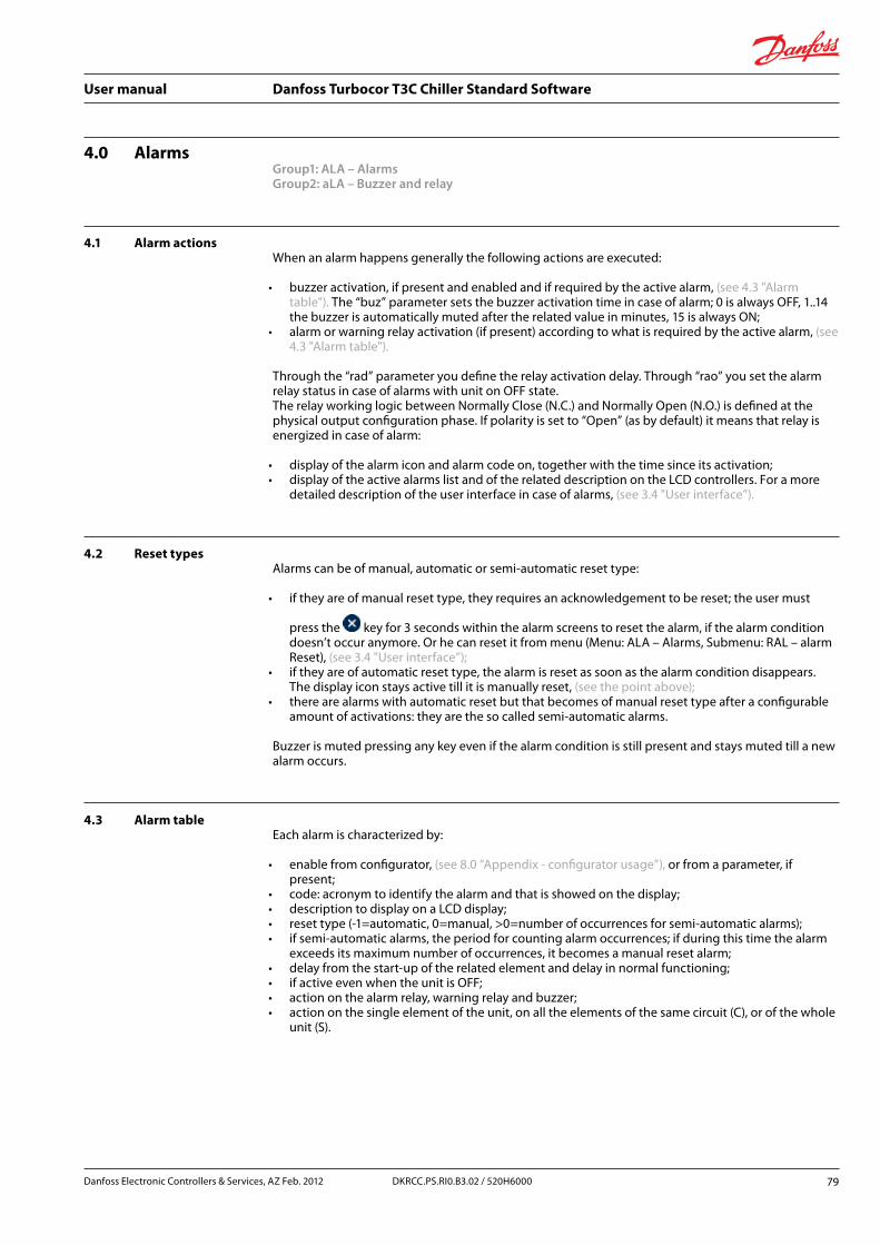
User manual Danfoss Turbocor T3C Chiller Standard Software
4.0 AlarmsGroup1: ALA – Alarms Group2: aLA – Buzzer and relay
4.1 Alarm actionsWhen an alarm happens generally the following actions are executed:
• buzzer activation, if present and enabled and if required by the active alarm, (see 4.3 "Alarm table"). The “buz” parameter sets the buzzer activation time in case of alarm; 0 is always OFF, 1..14 the buzzer is automatically muted after the related value in minutes, 15 is always ON;
• alarm or warning relay activation (if present) according to what is required by the active alarm, (see 4.3 "Alarm table").
Through the “rad” parameter you define the relay activation delay. Through “rao” you set the alarm relay status in case of alarms with unit on OFF state. The relay working logic between Normally Close (N.C.) and Normally Open (N.O.) is defined at the physical output configuration phase. If polarity is set to “Open” (as by default) it means that relay is energized in case of alarm:
• display of the alarm icon and alarm code on, together with the time since its activation; • display of the active alarms list and of the related description on the LCD controllers. For a more
detailed description of the user interface in case of alarms, (see 3.4 "User interface”).
4.2 Reset typesAlarms can be of manual, automatic or semi-automatic reset type:
• if they are of manual reset type, they requires an acknowledgement to be reset; the user must
press the key for 3 seconds within the alarm screens to reset the alarm, if the alarm condition doesn’t occur anymore. Or he can reset it from menu (Menu: ALA – Alarms, Submenu: RAL – alarm Reset), (see 3.4 "User interface”);
• if they are of automatic reset type, the alarm is reset as soon as the alarm condition disappears. The display icon stays active till it is manually reset, (see the point above);
• there are alarms with automatic reset but that becomes of manual reset type after a configurable amount of activations: they are the so called semi-automatic alarms.
Buzzer is muted pressing any key even if the alarm condition is still present and stays muted till a new alarm occurs.
4.3 Alarm tableEach alarm is characterized by:
• enable from configurator, (see 8.0 “Appendix - configurator usage”), or from a parameter, if present;
• code: acronym to identify the alarm and that is showed on the display; • description to display on a LCD display; • reset type (-1=automatic, 0=manual, >0=number of occurrences for semi-automatic alarms); • if semi-automatic alarms, the period for counting alarm occurrences; if during this time the alarm
exceeds its maximum number of occurrences, it becomes a manual reset alarm; • delay from the start-up of the related element and delay in normal functioning; • if active even when the unit is OFF; • action on the alarm relay, warning relay and buzzer; • action on the single element of the unit, on all the elements of the same circuit (C), or of the whole
unit (S).
Danfoss Electronic Controllers & Services, AZ Feb. 2012 79DKRCC.PS.RI0.B3.02 / 520H6000
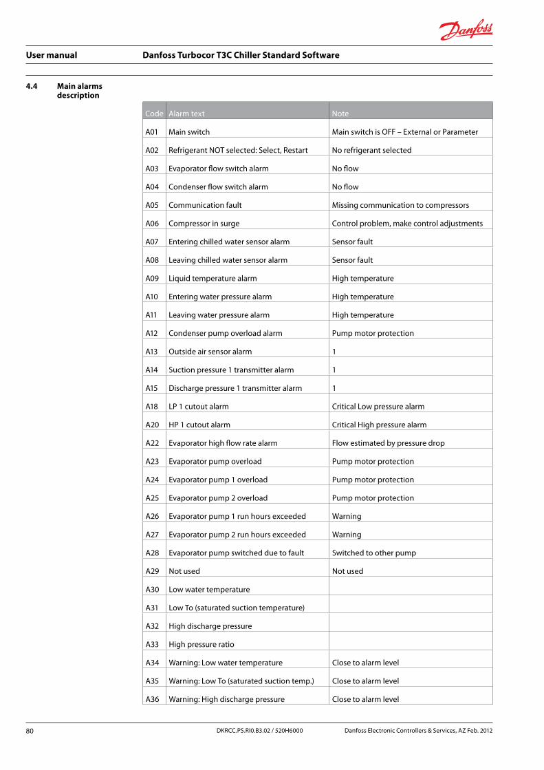
User manual Danfoss Turbocor T3C Chiller Standard Software
4.4 Main alarms description
Code Alarm text Note
A01 Main switch Main switch is OFF – External or Parameter
A02 Refrigerant NOT selected: Select, Restart No refrigerant selected
A03 Evaporator flow switch alarm No flow
A04 Condenser flow switch alarm No flow
A05 Communication fault Missing communication to compressors
A06 Compressor in surge Control problem, make control adjustments
A07 Entering chilled water sensor alarm Sensor fault
A08 Leaving chilled water sensor alarm Sensor fault
A09 Liquid temperature alarm High temperature
A10 Entering water pressure alarm High temperature
A11 Leaving water pressure alarm High temperature
A12 Condenser pump overload alarm Pump motor protection
A13 Outside air sensor alarm 1
A14 Suction pressure 1 transmitter alarm 1
A15 Discharge pressure 1 transmitter alarm 1
A18 LP 1 cutout alarm Critical Low pressure alarm
A20 HP 1 cutout alarm Critical High pressure alarm
A22 Evaporator high flow rate alarm Flow estimated by pressure drop
A23 Evaporator pump overload Pump motor protection
A24 Evaporator pump 1 overload Pump motor protection
A25 Evaporator pump 2 overload Pump motor protection
A26 Evaporator pump 1 run hours exceeded Warning
A27 Evaporator pump 2 run hours exceeded Warning
A28 Evaporator pump switched due to fault Switched to other pump
A29 Not used Not used
A30 Low water temperature
A31 Low To (saturated suction temperature)
A32 High discharge pressure
A33 High pressure ratio
A34 Warning: Low water temperature Close to alarm level
A35 Warning: Low To (saturated suction temp.) Close to alarm level
A36 Warning: High discharge pressure Close to alarm level
80 DKRCC.PS.RI0.B3.02 / 520H6000 Danfoss Electronic Controllers & Services, AZ Feb. 2012

User manual Danfoss Turbocor T3C Chiller Standard Software
Code Alarm text Note
A37 Warning: High pressure ratio Close to alarm level
A38 Liquid level sensor alarm Warning only
A39 High Liquid Level 1 Warning only
A40 Low Liquid Level 1 Warning only
A41 High Liquid Level 2 Not used
A42 Low Liquid Level 2 Not used
A43 Inverter fan 1 overload alarm Inverter relay disengaged
A44 Condenser fan 1 overload alarm Alarm, fan stopped
A45 Condenser fan 2 overload alarm Alarm, fan stopped
A46 Condenser fan 3 overload alarm Alarm, fan stopped
A47 Condenser fan 4 overload alarm Alarm, fan stopped
A48 Condenser fan 5 overload alarm Alarm, fan stopped
A49 Condenser fan 6 overload alarm Alarm, fan stopped
A50 Condenser fan 7 overload alarm Alarm, fan stopped
A51 Condenser fan 8 overload alarm Alarm, fan stopped
A52 Free cooling freeze error Stop compressor & fans, Start pumps & set valve to 100%
A53 General DI alarm 1 General digital input alarm
A54 General DI alarm 2 General digital input alarm
A55 General DI alarm 3 General digital input alarm
A56 General DI alarm 4 General digital input alarm
A57 General DI alarm 5 General digital input alarm
A58 General DI alarm 6 General digital input alarm
A59 General DI alarm 7 General digital input alarm
A60 General DI alarm 8 General digital input alarm
A61 General DI alarm 9 General digital input alarm
A62 General DI alarm 10 General digital input alarm
A63 General analogue input alarm
A64 General AI alarm 2 General analogue input alarm
A65 General AI alarm 3 General analogue input alarm
A66 General AI alarm 4 General analogue input alarm
A67 General AI alarm 5 General analogue input alarm
A68 General AI alarm 6 General analogue input alarm
A69 General AI alarm 7 General analogue input alarm
Danfoss Electronic Controllers & Services, AZ Feb. 2012 81DKRCC.PS.RI0.B3.02 / 520H6000

User manual Danfoss Turbocor T3C Chiller Standard Software
Code Alarm text Note
A70 General AI alarm 8 General analogue input alarm
A71 General AI alarm 9 General analogue input alarm
A72 General AI alarm 10 General analogue input alarm
A73 Common interlock activated Common interlock
A74 Compressor 1 interlock activated Compressor 1 interlock
A75 Compressor 2 interlock activated Compressor 2 interlock
A76 Compressor 3 interlock activated Compressor 3 interlock
A77 Compressor 4 interlock activated Compressor 4 interlock
A78 Evaporator heaters overload Heater alarm, heaters set off
A79 Evaporator heater 1 overload Heater alarm, heater set off
A80 Evaporator heater 2 overload Heater alarm, heater set off
A81 Evaporator heater 3 overload Heater alarm, heater set off
A82 Evaporator heater 4 overload Heater alarm, heater set off
A83 Evap. Condenser water level Low/high alarm for water level
A84 Evap. Condenser heaters Heater alarm, heaters set off
A85 Adiabatic Pump overload Pump motor protection
A86 Cooling enable off User activated stop of cooling
A87 Scheduled action Not used
A88 Scheduler list cleared Not used
A89 Parameters reset to default Not used
A90 Capacity limited Chiller capacity is limited to a value less than 100%
A91 Phase/Sequence alarm Alarm from external Phase/Sequence monitor
aux Aux device communication error Not used
aC1 TC1 communication error Critical compressor alarm- No communication to compressor
a11 TC1 AC - Inverter Temperature Critical compressor alarm- Inverter Temperature
a12 TC1 AC - Discharge Temp Critical compressor alarm- Discharge Temp
a13 TC1 AC - Suction Pressure Critical compressor alarm- Suction Pressure
a14 TC1 AC - Discharge Pressure Critical compressor alarm- Discharge Pressure
a15 TC1 AC - 3 Phase Current Trip Critical compressor alarm- 3 Phase Current Trip
82 DKRCC.PS.RI0.B3.02 / 520H6000 Danfoss Electronic Controllers & Services, AZ Feb. 2012

User manual Danfoss Turbocor T3C Chiller Standard Software
Code Alarm text Note
a16 TC1 AC - Shaft Cavity Temperature Critical compressor alarm- Shaft Cavity Temperature
a17 TC1 AC - Leaving Air /Water Critical compressor alarm- Leaving Air /Water
a18 TC1 AC - Total Compression Ratio Fault Critical compressor alarm- Total Compression Ratio Fault
a19 TC1 AC - Bearing Motor Fault Critical compressor alarm- Bearing Motor Fault
a1A TC1 AC - Sensor error Critical compressor alarm- Sensor error
a1B TC1 AC - SCR Fault Critical compressor alarm- SCR Fault
a1C TC1 AC - Lock out Fault Critical compressor alarm- Lock out Fault
a1D TC1 AC - Motor Thermistor Critical compressor alarm- Motor Thermistor
a1E TC1 AC - Super Heat Fault Critical compressor alarm- Super Heat Fault
a1F TC1 ANC - Inverter Temperature Non critical compressor alarm- Inverter Temperature
a1G TC1 ANC - Discharge Temp Non critical compressor alarm- Discharge Temp
a1H TC1 ANC - Suction Pressure Non critical compressor alarm- Suction Pressure
a1I TC1 ANC - Discharge Pressure Non critical compressor alarm- Discharge Pressure
a1J TC1 ANC - 3 Phase Current Trip Non critical compressor alarm- 3 Phase Current Trip
a1K TC1 ANC - Shaft Cavity Temperature Non critical compressor alarm- Shaft Cavity Temperature
a1L TC1 ANC - Leaving Water Non critical compressor alarm- Leaving Water
a1M TC1 ANC - Total Compression Ratio Fault Non critical compressor alarm- Total Compression Ratio Fault
a1N TC1 ANC - SCR Temperature Non critical compressor alarm- SCR Temperature
a1O TC1 ANC - Super Heat Non critical compressor alarm- Super Heat
aC2 TC2 communication error Critical compressor alarm- No communication to compressor
a21 TC2 AC - Inverter Temperature Critical compressor alarm- Inverter Temperature
a22 TC2 AC - Discharge Temp Critical compressor alarm- Discharge Temp
Danfoss Electronic Controllers & Services, AZ Feb. 2012 83DKRCC.PS.RI0.B3.02 / 520H6000
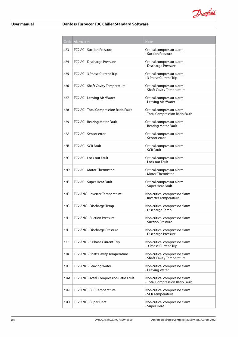
User manual Danfoss Turbocor T3C Chiller Standard Software
Code Alarm text Note
a23 TC2 AC - Suction Pressure Critical compressor alarm- Suction Pressure
a24 TC2 AC - Discharge Pressure Critical compressor alarm- Discharge Pressure
a25 TC2 AC - 3 Phase Current Trip Critical compressor alarm- 3 Phase Current Trip
a26 TC2 AC - Shaft Cavity Temperature Critical compressor alarm- Shaft Cavity Temperature
a27 TC2 AC - Leaving Air /Water Critical compressor alarm- Leaving Air /Water
a28 TC2 AC - Total Compression Ratio Fault Critical compressor alarm- Total Compression Ratio Fault
a29 TC2 AC - Bearing Motor Fault Critical compressor alarm- Bearing Motor Fault
a2A TC2 AC - Sensor error Critical compressor alarm- Sensor error
a2B TC2 AC - SCR Fault Critical compressor alarm- SCR Fault
a2C TC2 AC - Lock out Fault Critical compressor alarm- Lock out Fault
a2D TC2 AC - Motor Thermistor Critical compressor alarm- Motor Thermistor
a2E TC2 AC - Super Heat Fault Critical compressor alarm- Super Heat Fault
a2F TC2 ANC - Inverter Temperature Non critical compressor alarm- Inverter Temperature
a2G TC2 ANC - Discharge Temp Non critical compressor alarm- Discharge Temp
a2H TC2 ANC - Suction Pressure Non critical compressor alarm- Suction Pressure
a2I TC2 ANC - Discharge Pressure Non critical compressor alarm- Discharge Pressure
a2J TC2 ANC - 3 Phase Current Trip Non critical compressor alarm- 3 Phase Current Trip
a2K TC2 ANC - Shaft Cavity Temperature Non critical compressor alarm- Shaft Cavity Temperature
a2L TC2 ANC - Leaving Water Non critical compressor alarm- Leaving Water
a2M TC2 ANC - Total Compression Ratio Fault Non critical compressor alarm- Total Compression Ratio Fault
a2N TC2 ANC - SCR Temperature Non critical compressor alarm- SCR Temperature
a2O TC2 ANC - Super Heat Non critical compressor alarm- Super Heat
84 DKRCC.PS.RI0.B3.02 / 520H6000 Danfoss Electronic Controllers & Services, AZ Feb. 2012

User manual Danfoss Turbocor T3C Chiller Standard Software
Code Alarm text Note
aC3 TC3 communication error Critical compressor alarm- No communication to compressor
a31 TC3 AC - Inverter Temperature Critical compressor alarm- Inverter Temperature
a32 TC3 AC - Discharge Temp Critical compressor alarm- Discharge Temp
a33 TC3 AC - Suction Pressure Critical compressor alarm- Suction Pressure
a34 TC3 AC - Discharge Pressure Critical compressor alarm- Discharge Pressure
a35 TC3 AC - 3 Phase Current Trip Critical compressor alarm- 3 Phase Current Trip
a36 TC3 AC - Shaft Cavity Temperature Critical compressor alarm- Shaft Cavity Temperature
a37 TC3 AC - Leaving Air /Water Critical compressor alarm- Leaving Air /Water
a38 TC3 AC - Total Compression Ratio Fault Critical compressor alarm- Total Compression Ratio Fault
a39 TC3 AC - Bearing Motor Fault Critical compressor alarm- Bearing Motor Fault
a3A TC3 AC - Sensor error Critical compressor alarm- Sensor error
a3B TC3 AC - SCR Fault Critical compressor alarm- SCR Fault
a3C TC3 AC - Lock out Fault Critical compressor alarm- Lock out Fault
a3D TC3 AC - Motor Thermistor Critical compressor alarm- Motor Thermistor
a3E TC3 ANC - Super Heat Critical compressor alarm- Super Heat Fault
a3F TC3 ANC - Inverter Temperature Non critical compressor alarm- Inverter Temperature
a3G TC3 ANC - Discharge Temp Non critical compressor alarm- Discharge Temp
a3H TC3 ANC - Suction Pressure Non critical compressor alarm- Suction Pressure
a3I TC3 ANC - Discharge Pressure Non critical compressor alarm- Discharge Pressure
a3J TC3 ANC - 3 Phase Current Trip Non critical compressor alarm- 3 Phase Current Trip
a3K TC3 ANC - Shaft Cavity Temperature Non critical compressor alarm- Shaft Cavity Temperature
a3L TC3 ANC - Leaving Water Non critical compressor alarm- Leaving Water
Danfoss Electronic Controllers & Services, AZ Feb. 2012 85DKRCC.PS.RI0.B3.02 / 520H6000

User manual Danfoss Turbocor T3C Chiller Standard Software
Code Alarm text Note
a3M TC3 ANC - Total Compression Ratio Fault Non critical compressor alarm- Total Compression Ratio Fault
a3N TC3 ANC - SCR Temperature Non critical compressor alarm- SCR Temperature
a3O TC3 ANC - Super Heat Non critical compressor alarm- Super Heat
aC4 TC4 communication error Critical compressor alarm- No communication to compressor
a41 TC4 AC - Inverter Temperature Critical compressor alarm- Inverter Temperature
a42 TC4 AC - Discharge Temp Critical compressor alarm- Discharge Temp
a43 TC4 AC - Suction Pressure Critical compressor alarm- Suction Pressure
a44 TC4 AC - Discharge Pressure Critical compressor alarm- Discharge Pressure
a45 TC4 AC - 3 Phase Current Trip Critical compressor alarm- 3 Phase Current Trip
a46 TC4 AC - Shaft Cavity Temperature Critical compressor alarm- Shaft Cavity Temperature
a47 TC4 AC - Leaving Air /Water Critical compressor alarm- Leaving Air /Water
a48 TC4 AC - Total Compression Ratio Fault Critical compressor alarm- Total Compression Ratio Fault
a49 TC4 AC - Bearing Motor Fault Critical compressor alarm- Bearing Motor Fault
a4A TC4 AC - Sensor error Critical compressor alarm- Sensor error
a4B TC4 AC - SCR Fault Critical compressor alarm- SCR Fault
a4C TC4 AC - Lock out Fault Critical compressor alarm- Lock out Fault
a4D TC4 AC - Motor Thermistor Critical compressor alarm- Motor Thermistor
a4E TC4 ANC - Super Heat Critical compressor alarm- Super Heat Fault
a4F TC4 ANC - Inverter Temperature Non critical compressor alarm- Inverter Temperature
a4G TC4 ANC - Discharge Temp Non critical compressor alarm- Discharge Temp
a4H TC4 ANC - Suction Pressure Non critical compressor alarm- Suction Pressure
a4I TC4 ANC - Discharge Pressure Non critical compressor alarm- Discharge Pressure
86 DKRCC.PS.RI0.B3.02 / 520H6000 Danfoss Electronic Controllers & Services, AZ Feb. 2012

User manual Danfoss Turbocor T3C Chiller Standard Software
Code Alarm text Note
a4J TC4 ANC - 3 Phase Current Trip Non critical compressor alarm- 3 Phase Current Trip
a4K TC4 ANC - Shaft Cavity Temperature Non critical compressor alarm- Shaft Cavity Temperature
a4L TC4 ANC - Leaving Water Non critical compressor alarm- Leaving Water
a4M TC4 ANC - Total Compression Ratio Fault Non critical compressor alarm- Total Compression Ratio Fault
a4N TC4 ANC - SCR Temperature Non critical compressor alarm- SCR Temperature
a4O TC4 ANC - Super Heat Non critical compressor alarm- Super Heat
A92 Evaporator low flow rate alarm Based on pressure drop
A93 Condenser high flow rate alarm Based on pressure drop
A94 Condenser low flow rate alarm Based on pressure drop
Tab 28 [Alarms - Main alarm description]
Danfoss Electronic Controllers & Services, AZ Feb. 2012 87DKRCC.PS.RI0.B3.02 / 520H6000

User manual Danfoss Turbocor T3C Chiller Standard Software
5.0 ParametersPlease (see MCXShape user manual).
5.1 Parameters tablePlease (see 8.0 “Appendix - configurator usage”).
88 DKRCC.PS.RI0.B3.02 / 520H6000 Danfoss Electronic Controllers & Services, AZ Feb. 2012
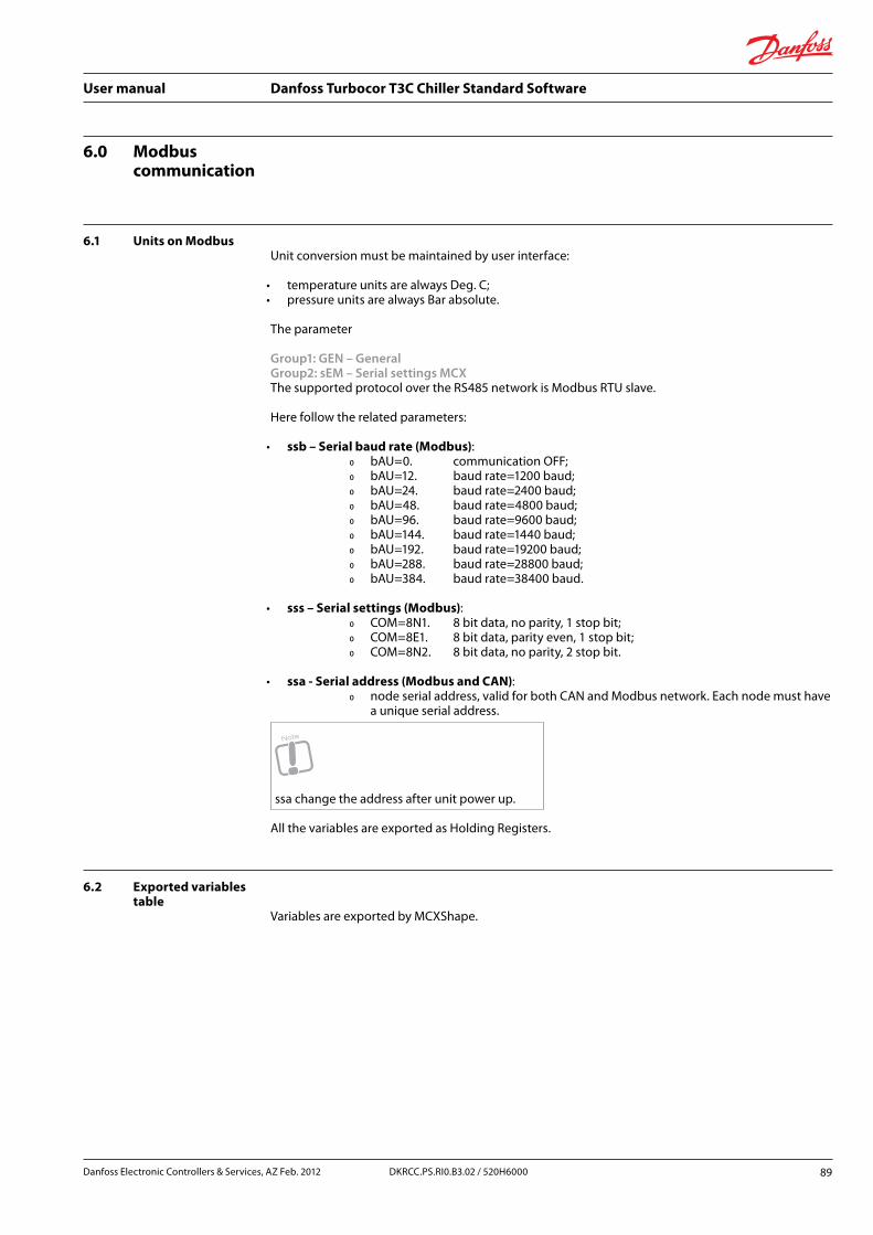
User manual Danfoss Turbocor T3C Chiller Standard Software
6.0 Modbus communication
6.1 Units on ModbusUnit conversion must be maintained by user interface:
• temperature units are always Deg. C; • pressure units are always Bar absolute.
The parameter
Group1: GEN – GeneralGroup2: sEM – Serial settings MCXThe supported protocol over the RS485 network is Modbus RTU slave.
Here follow the related parameters:
• ssb – Serial baud rate (Modbus): Ř bAU=0. communication OFF; Ř bAU=12. baud rate=1200 baud; Ř bAU=24. baud rate=2400 baud; Ř bAU=48. baud rate=4800 baud; Ř bAU=96. baud rate=9600 baud; Ř bAU=144. baud rate=1440 baud; Ř bAU=192. baud rate=19200 baud; Ř bAU=288. baud rate=28800 baud; Ř bAU=384. baud rate=38400 baud.
• sss – Serial settings (Modbus): Ř COM=8N1. 8 bit data, no parity, 1 stop bit; Ř COM=8E1. 8 bit data, parity even, 1 stop bit; Ř COM=8N2. 8 bit data, no parity, 2 stop bit.
• ssa - Serial address (Modbus and CAN): Ř node serial address, valid for both CAN and Modbus network. Each node must have
a unique serial address.
Note
ssa change the address after unit power up.
All the variables are exported as Holding Registers.
6.2 Exported variables table
Variables are exported by MCXShape.
Danfoss Electronic Controllers & Services, AZ Feb. 2012 89DKRCC.PS.RI0.B3.02 / 520H6000

User manual Danfoss Turbocor T3C Chiller Standard Software
7.0 Graphic diagrams of some of the managed unit types
7.1 Air/Water
Air/Water chiller, 1 circui
Fig 26 [Graphic diagrams - Air/Water chiller, 1 circuit]
90 DKRCC.PS.RI0.B3.02 / 520H6000 Danfoss Electronic Controllers & Services, AZ Feb. 2012

User manual Danfoss Turbocor T3C Chiller Standard Software
7.2 Water/Water
Water/Water chiller, 1 circuit
Fig 27 [Graphic diagrams - Water/Water chiller, 1 circuit]
Danfoss Electronic Controllers & Services, AZ Feb. 2012 91DKRCC.PS.RI0.B3.02 / 520H6000

User manual Danfoss Turbocor T3C Chiller Standard Software
8.0 Appendix – configurator usage
Must be modified according to MCXShape
Parameter “ver” “Database version” Version number of the parameter settings file. This is only changed when the file layout is changed, not when parameter values are changed.
You can modify the management of parameters and alarms using the software configurator “Interface.xls”.
You also need a USB-to-485 adapter to connect your PC to the RS485 port of a MCX.
8.1 Adapter installation1. connect the USBto485 adapter to your PC and follow the on-line instructions using the drivers
provided with the converter;2. after installation is completed, look at the COM port where the USBto485 adapter is installed
(COM10 in figure);
Fig 28 [Appendix - configurator usage - Adapter installation]
92 DKRCC.PS.RI0.B3.02 / 520H6000 Danfoss Electronic Controllers & Services, AZ Feb. 2012

User manual Danfoss Turbocor T3C Chiller Standard Software
3. modify the NewApp.bat file, that is a batch file provided together with the application software to compile and to upload the modified software into the MCX, in order to make it use the COM port where the adapter is installed: ..... nupload -com10 main.cpp.o .....
8.2 Guide for application software modification
To modify the application software:
1. open the software configurator “Interface.xls”;2. go to the “Generate” tab and select the desired MCX model and language;3. make the changes you want entering into the appropriate tab.
It is possible to change the following items: Ř navigation menu, from the “Main_Menu” tab; Ř parameters, from “Parameters” and “Parameters_x_Model” tabs; Ř alarms, from the “Alarms” tab; Ř input and output configuration, from “Digital_Input”, “Digital_Output”, “Analog_
Input”, “Analog_Output” tabs. For details on how to make changes refer to the next chapters, related to each single tab;
4. go to the “Generate” tab and press the “Generate” button. In this way you generate a new version of “*.c” source files related to parameters and alarms;
5. run the “NewApp.bat” batch file, with the MCX controller powered ON and connected through the USBto485 converter. You will see a DOS window with information on compiling and uploading status. At the end you should (see “Upload complete”). Now the changes are active.
8.3 “Parameters” tabFrom the “Parameters” tab, you can change the following items for each parameter:
• identification code shown on the LED display (“Code” column); • description shown on LCD display.
Note
To change the description do not change the “Current Description” column that is read only (See the description in the language selected inside the “Generate” tab), but the one starting with the suffix of the desired language and located at the right side of the “Parameters” tab, from “S” column on; i.e. “EN Description” for English language.
Danfoss Electronic Controllers & Services, AZ Feb. 2012 93DKRCC.PS.RI0.B3.02 / 520H6000

User manual Danfoss Turbocor T3C Chiller Standard Software
8.4 “Alarms” tabIn the “Alarms” tab, for each alarm you can change:
• identification code showed on the LED display (“Code” column); • description, (see the note above); • alarm enable (“Enable” column); • reset type (“Reset type” column). -1=automatic reset, 0=manual reset, >0 = number of occurrences
of the alarm before its reset types changes from manual to automatic; • the period for counting alarm occurrences in case of semi-automatic alarms (“Semiautomatic
Period” column). If during this time the alarm exceeds its maximum number of occurrences defined in the previous column “Reset Type”, the alarm reset type changes from automatic to manual;
• delay at start-up of the related element (“Startup delay” column) and delay in normal functioning (“Steady delay” column);
• if active even when the unit is OFF (“Active with unit OFF” column); • action on the alarm and warning relay (“Alarm relay”, “Warning relay” columns); • action on the elements of the unit (“Compressors“, “Fan or Pump Evap.”, “Fan or Pump Cond.”,
heaters” columns): Ř “ON”: the element is forced to ON; Ř “OFF”: the element is forced to OFF; Ř “-“: the element is left in its previous status;
Note
From the configurator it is not possible to change the action on the elements to ON. All the other changes are allowed.
• in the “Circuit or System” column, if the action is on the single element, on all the elements of the same circuit ©, or of the whole unit (S).
coloumn "Interlock relay”:
• “-": no interlock action; • "OFF" force stop to compressors; • "INTERLOCK" force stop to compressors and take the interlock relay.
8.5 “Parameters_x_ Model” tab
This tab allows you to give different “K” attribute, minimum, maximum and default values to parameters depending on the MCX model. In this tab you can add all parameters having different values according to the hardware where the software is running on. If a parameter is present in this tab, when you select the MCX model from the “Generate” tab through the drop down menu, all the values of that parameter will be automatically copied from the “Parameters_x_Model” tab to the “Parameters” tab. These will be the new current values.
Note
The format of the copied parameters inside the “Params” tab is changed using the bold and green colour format. The purpose is to underline that eventual further changes to these parameters should be done inside the “Parameters_x_Model” tab. In fact, if the change would be done directly on “Parameters” tab, it could be lost when selecting a new MCX model.
94 DKRCC.PS.RI0.B3.02 / 520H6000 Danfoss Electronic Controllers & Services, AZ Feb. 2012
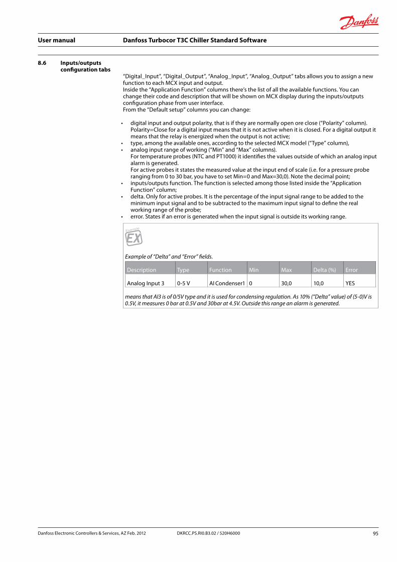
User manual Danfoss Turbocor T3C Chiller Standard Software
8.6 Inputs/outputs configuration tabs
“Digital_Input”, “Digital_Output”, “Analog_Input”, “Analog_Output” tabs allows you to assign a new function to each MCX input and output. Inside the “Application Function” columns there’s the list of all the available functions. You can change their code and description that will be shown on MCX display during the inputs/outputs configuration phase from user interface. From the “Default setup” columns you can change:
• digital input and output polarity, that is if they are normally open ore close (“Polarity” column). Polarity=Close for a digital input means that it is not active when it is closed. For a digital output it means that the relay is energized when the output is not active;
• type, among the available ones, according to the selected MCX model (“Type” column), • analog input range of working (“Min” and “Max” columns).
For temperature probes (NTC and PT1000) it identifies the values outside of which an analog input alarm is generated. For active probes it states the measured value at the input end of scale (i.e. for a pressure probe ranging from 0 to 30 bar, you have to set Min=0 and Max=30,0). Note the decimal point;
• inputs/outputs function. The function is selected among those listed inside the “Application Function” column;
• delta. Only for active probes. It is the percentage of the input signal range to be added to the minimum input signal and to be subtracted to the maximum input signal to define the real working range of the probe;
• error. States if an error is generated when the input signal is outside its working range.
Example
Example of “Delta” and “Error” fields.
Description Type Function Min Max Delta (%) Error
Analog Input 3 0-5 V AI Condenser1 0 30,0 10,0 YES
means that AI3 is of 0/5V type and it is used for condensing regulation. As 10% (“Delta” value) of (5-0)V is 0.5V, it measures 0 bar at 0.5V and 30bar at 4.5V. Outside this range an alarm is generated.
Danfoss Electronic Controllers & Services, AZ Feb. 2012 95DKRCC.PS.RI0.B3.02 / 520H6000
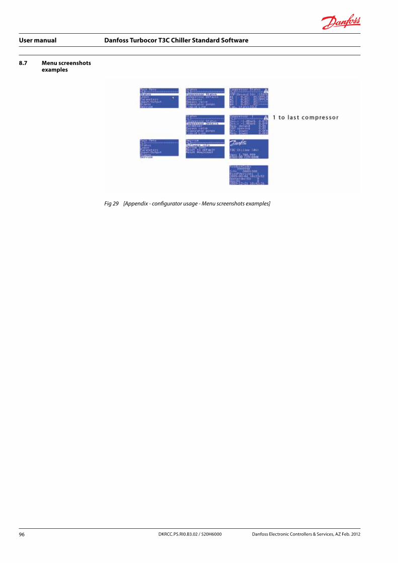
User manual Danfoss Turbocor T3C Chiller Standard Software
8.7 Menu screenshots examples
Fig 29 [Appendix - configurator usage - Menu screenshots examples]
96 Danfoss Electronic Controllers & Services, AZ Feb. 2012DKRCC.PS.RI0.B3.02 / 520H6000

User manual Danfoss Turbocor T3C Chiller Standard Software
Danfoss Electronic Controllers & Services, AZ Feb. 2012 97DKRCC.PS.RI0.B3.02 / 520H6000

User manual Danfoss Turbocor T3C Chiller Standard Software
Table indexTab 1 [Configuration - Product information] 12Tab 2 [Configuration - Digital inputs configuration] 15Tab 3 [Configuration - Configuration example] 16Tab 4 [Configuration - Digital input for flow evaporatorand condenser] 16Tab 5 [Configuration - Digital outputs] 19Tab 6 [Configuration - Analog inputs] 21Tab 7 [Configuration - Analog outputs] 22Tab 8 [Configuration - Serial setting Turbocor] 24Tab 9 [Configuration - Parameters for compressors] 25Tab 10 [Configuration - Parameters for evaporator] 28Tab 11 [Configuration - Evaporator flow] 30Tab 12 [Configuration - Parameters for functions] 32Tab 13 [Configuration - Affected alarms] 33Tab 14 [Configuration - Parameters for input calibration] 34Tab 15 [Configuration - Menu navigation] 36Tab 16 [Configuration - Keyboard] 39Tab 17 [Configuration - Main switch] 40Tab 18 [Configuration - Cooling enable] 41Tab 19 [Configuration - Economizer] 52Tab 20 [Configuration - Active power feedback] 53Tab 21 [Configuration - Level injection control] 55Tab 22 [Configuration - Condenser configuration] 58Tab 23 [Configuration - Parameters for condenser control] 62Tab 24 [Configuration - Air condensing unit] 64Tab 25 [Configuration - Free-cooling] 70Tab 26 [Configuration - Digital inputs] 76Tab 27 [Configuration - Analog inputs] 77Tab 28 [Alarms - Main alarm description] 87
98 DKRCC.PS.RI0.B3.02 / 520H6000 Danfoss Electronic Controllers & Services, AZ Feb. 2012
User manual Danfoss Turbocor T3C Chiller Standard Software
Image indexFig 1 [Introduction - MCX Turbocor] 5Fig 2 [Compressor control - Chiller state] 6Fig 3 [Compressor control - Individual compressors states] 7Fig 4 [Compressor control - Turbocor software release note PSS-SRN-00010, Rev 1] 11Fig 5 [Configuration - Parameters for chiller safety configuration] 31Fig 6 [Configuration - LCD display] 35Fig 7 [Configuration - Inputs/outputs LCD display] 37Fig 8 [Configuration - Cooling enable] 41Fig 9 [Configuration - Cold reference] 44Fig 10 [Configuration - Temperature] 45Fig 11 [Configuration - Offset] 46Fig 12 [Configuration - Compressors] 48Fig 13 [Configuration - Hot gas] 49Fig 14 [Configuration - Bypass] 50Fig 15 [Configuration - Economizer principle diagram A] 51Fig 16 [Compressor control - Economizer principle diagram B - multiple compressors] 52Fig 17 [Configuration - Mode "Ce1"=ON] 56Fig 18 [Configuration - Regulation] 57Fig 19 [Configuration - Condenser reference] 61Fig 20 [Configuration - Fan speed regulation] 65Fig 21 [Configuration - Water valve] 66Fig 22 [Configuration - Water tower] 67Fig 23 [Configuration - Water free-cooling] 69Fig 24 [Configuration - Free-cooling valve management] 71Fig 25 [Configuration - Fan management in free-cooling] 72Fig 26 [Graphic diagrams - Air/Water chiller, 1 circuit] 90Fig 27 [Graphic diagrams - Water/Water chiller, 1 circuit] 91Fig 28 [Appendix - configurator usage - Adapter installation] 92Fig 29 [Appendix - configurator usage - Menu screenshots examples] 96
Danfoss Electronic Controllers & Services, AZ Feb. 2012 99DKRCC.PS.RI0.B3.02 / 520H6000

User manual Danfoss Turbocor T3C Chiller Standard Software
100 Danfoss Electronic Controllers & Services, AZ Feb. 2012DKRCC.PS.RI0.B3.02 / 520H6000