incremental linear encoders - servo2go® · pdf fileincremental linear encoders enclosed...
TRANSCRIPT
1
Technik, die zähltTechnology that counts
Incremental Linear EncodersEnclosed Models
3
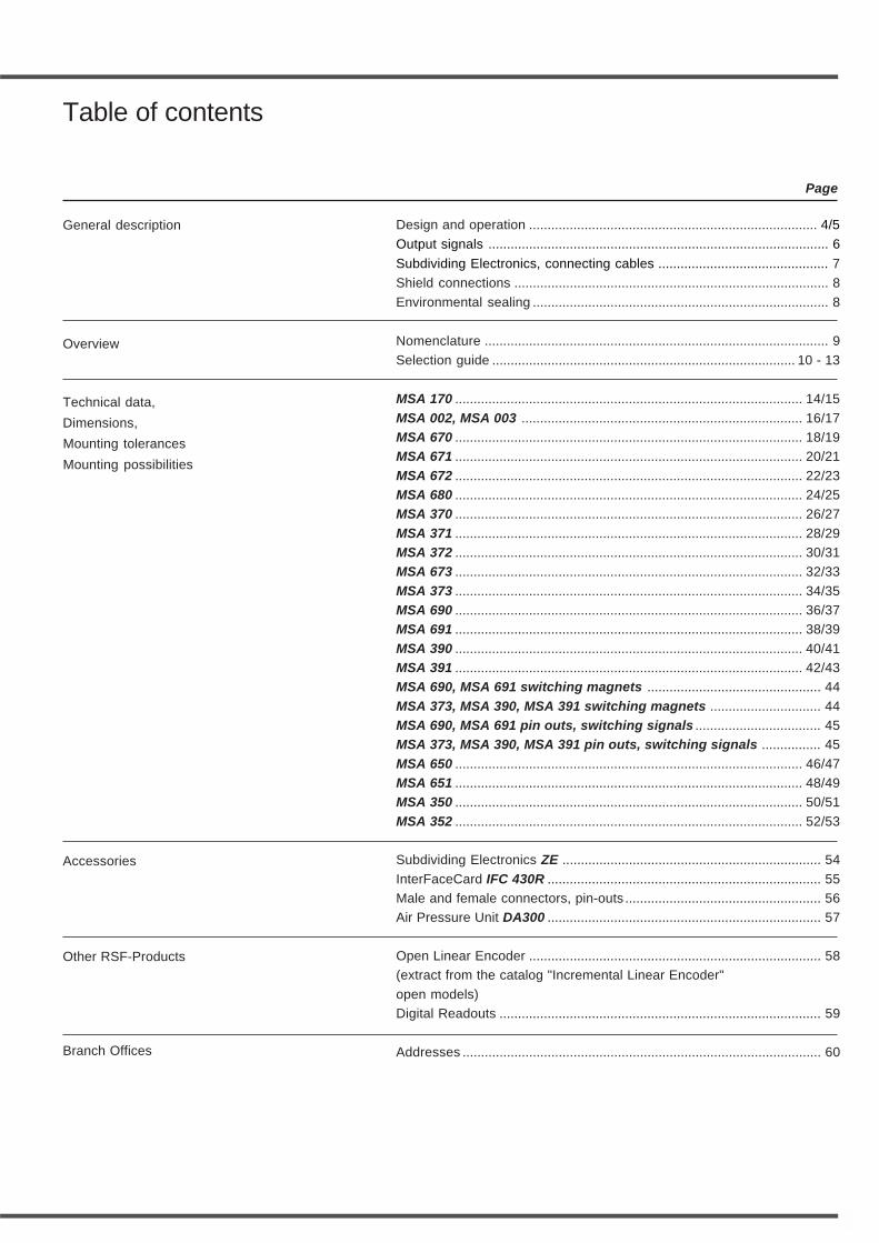
Table of contents
General description
Overview
Technical data,
Dimensions,
Mounting tolerances
Mounting possibilities
Accessories
Branch Offices
Page
Design and operation .............................................................................. 4/5
Output signals ............................................................................................ 6
Subdividing Electronics, connecting cables .............................................. 7
Shield connections ..................................................................................... 8
Environmental sealing ................................................................................ 8
Nomenclature ............................................................................................. 9
Selection guide .................................................................................. 10 - 13
MSA 170 .............................................................................................. 14/15
MSA 002, MSA 003 ............................................................................ 16/17MSA 670 .............................................................................................. 18/19MSA 671 .............................................................................................. 20/21
MSA 672 .............................................................................................. 22/23MSA 680 .............................................................................................. 24/25MSA 370 .............................................................................................. 26/27
MSA 371 .............................................................................................. 28/29MSA 372 .............................................................................................. 30/31MSA 673 .............................................................................................. 32/33
MSA 373 .............................................................................................. 34/35MSA 690 .............................................................................................. 36/37MSA 691 .............................................................................................. 38/39
MSA 390 .............................................................................................. 40/41MSA 391 .............................................................................................. 42/43MSA 690, MSA 691 switching magnets ............................................... 44
MSA 373, MSA 390, MSA 391 switching magnets .............................. 44MSA 690, MSA 691 pin outs, switching signals .................................. 45MSA 373, MSA 390, MSA 391 pin outs, switching signals ................ 45
MSA 650 .............................................................................................. 46/47MSA 651 .............................................................................................. 48/49MSA 350 .............................................................................................. 50/51
MSA 352 .............................................................................................. 52/53
Subdividing Electronics ZE ...................................................................... 54
InterFaceCard IFC 430R .......................................................................... 55Male and female connectors, pin-outs ..................................................... 56Air Pressure Unit DA300 .......................................................................... 57
Open Linear Encoder ............................................................................... 58(extract from the catalog "Incremental Linear Encoder"
open models)Digital Readouts ....................................................................................... 59
Addresses ................................................................................................. 60
Other RSF-Products

4
Enclosed Linear Encoders have a rollerbearing self-guided scanning carriage.The scanning carriage is spring loadedto track properly within the encoderhead mounting tolerance range. A set ofrare earth magnets couple the scanningcarriage to the mounting base of theencoder head.
scanning head
steel tape orglass scale
roller bearings
encoder head
magnetic coupling
glass scalescanning carriage
This magnetic coupling compensatesallowable mounting tolerances andmachine guide non-parallelism.Non-contact open encoders rely on theair gap between the encoder head andscale to be uniform over the measuringrange. The flatness of the mountingsurface and the parallelism of themachine guideway is important.
Design and operation
RSF manufactures linear encoders inenclosed and open versions.The enclosed models are easy to installwith large mounting tolerances.They are also best suited for harshenvironments. The sealing lips on theextrusion keep out coolants andcontamination.
extrusion
glass scale
encoder head sealing lips
scanning head
steel tape scaleor glass scale
The non-contact open measuringsystems are for high displacementvelocities and high accuracies,commonly used in clean environments.
Open systemswith non-contact scanning carriage
Enclosed systemswith guided scanning carriage
5
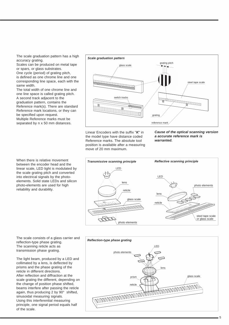
When there is relative movementbetween the encoder head and thelinear scale, LED light is modulated bythe scale grating pitch and convertedinto electrical signals by the photo-elements. Solid state LEDs and siliconphoto-elements are used for highreliability and durability.
Reflective scanning principleTransmissive scanning principle
LED
LED
lens
lensreticle
reticle
photo elements
photo elements
glass scale
steel tape scaleor glass scale
The scale graduation pattern has a highaccuracy grating.Scales can be produced on metal tapeor spars, or glass substrates.One cycle (period) of grating pitch,is defined as one chrome line and onecorresponding line space, each with thesame width.The total width of one chrome line andone line space is called grating pitch.A second track adjacent to thegraduation pattern, contains theReference mark(s). There are standardReference mark locations, or they canbe specified upon request.Multiple Reference marks must beseparated by n x 50 mm distances.
grating pitchglass scale
steel tape scale
grating
switch tracks
reference mark
The scale consists of a glass carrier andreflection-type phase grating.The scanning reticle acts astransmission phase grating.
The light beam, produced by a LED andcollimated by a lens, is deflected byprisms and the phase grating of thereticle in different directions.After reflection and diffraction at thescale grating the different, depending onthe change of position phase shifted,beams interfere after passing the reticleagain, thus producing 2 by 90° shifted,sinusoidal measuring signals.Using this interferential measuringprinciple, one signal period equals halfof the scale.
Scale graduation pattern
Linear Encoders with the suffix "K" inthe model type have distance codedReference marks. The absolute toolposition is available after a measuringmove of 20 mm maximum.
LED
glass scale
reticle
photo elements
lens
prism
Reflection-type phase grating
Cause of the optical scanning versiona accurate reference mark iswarranted.
6
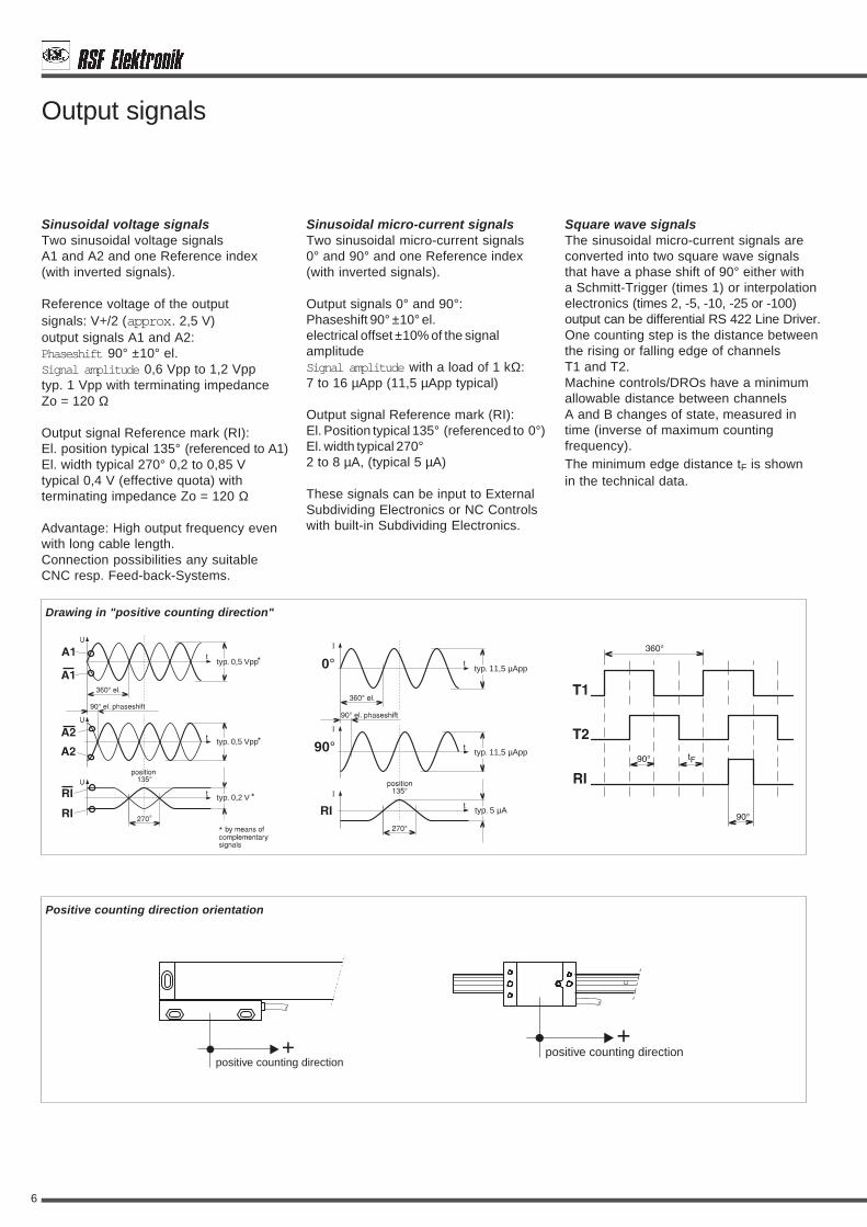
Output signals
Square wave signalsThe sinusoidal micro-current signals areconverted into two square wave signalsthat have a phase shift of 90° either witha Schmitt-Trigger (times 1) or interpolationelectronics (times 2, -5, -10, -25 or -100)output can be differential RS 422 Line Driver.One counting step is the distance betweenthe rising or falling edge of channelsT1 and T2.Machine controls/DROs have a minimumallowable distance between channelsA and B changes of state, measured intime (inverse of maximum countingfrequency).The minimum edge distance tF is shownin the technical data.
Sinusoidal voltage signalsTwo sinusoidal voltage signalsA1 and A2 and one Reference index(with inverted signals).
Reference voltage of the outputsignals: V+/2 (approx. 2,5 V)output signals A1 and A2:Phaseshift 90° ±10° el.Signal amplitude 0,6 Vpp to 1,2 Vpptyp. 1 Vpp with terminating impedanceZo = 120 Ω
Output signal Reference mark (RI):El. position typical 135° (referenced to A1)El. width typical 270° 0,2 to 0,85 Vtypical 0,4 V (effective quota) withterminating impedance Zo = 120 Ω
Advantage: High output frequency evenwith long cable length.Connection possibilities any suitableCNC resp. Feed-back-Systems.
typ. 0,5 Vpp
typ. 0,5 Vpp
typ. 0,2 V
Positive counting direction orientation
positive counting direction+
0°
90°
typ. 11,5 µApp
typ. 11,5 µApp
typ. 5 µA
Sinusoidal micro-current signalsTwo sinusoidal micro-current signals0° and 90° and one Reference index(with inverted signals).
Output signals 0° and 90°:Phaseshift 90° ±10° el.electrical offset ±10% of the signalamplitudeSignal amplitude with a load of 1 kΩ:7 to 16 µApp (11,5 µApp typical)
Output signal Reference mark (RI):El. Position typical 135° (referenced to 0°)El. width typical 270°2 to 8 µA, (typical 5 µA)
These signals can be input to ExternalSubdividing Electronics or NC Controlswith built-in Subdividing Electronics.
positive counting direction+
Drawing in "positive counting direction"
7
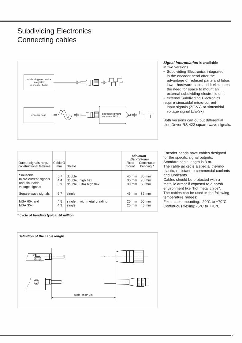
Subdividing ElectronicsConnecting cables
Signal interpolation is availablein two versions.• Subdividing Electronics integrated
in the encoder head offer theadvantage of reduced parts and labor,lower hardware cost, and it eliminatesthe need for space to mount anexternal subdividing electronic unit.
• external Subdividing Electronicsrequire sinusoidal micro-current
input signals (ZE-Vx) or sinusoidalvoltage signal (ZE-Sx)
Both versions can output differentialLine Driver RS 422 square wave signals.
Encoder heads have cables designedfor the specific signal outputs.Standard cable length is 3 m.The cable jacket is a special thermo-plastic, resistant to commercial coolantsand lubricants.Cables should be protected with ametallic armor if exposed to a harshenvironment like "hot metal chips".The cables can be used in the followingtemperature ranges:Fixed cable mounting: -20°C to +70°CContinuous flexing: -5°C to +70°C
Sinusoidal 5,7 double 45 mm 85 mmmicro-current signals 4,4 double, high flex 35 mm 70 mmand sinusoidal 3,9 double, ultra high flex 30 mm 60 mmvoltage signals
Square wave signals 5,7 single 45 mm 85 mm
MSA 65x and 4,8 single, with metal braiding 25 mm 50 mmMSA 35x 4,3 single 25 mm 45 mm
Definition of the cable length
ShieldCable Ø
mmOutput signals resp.constructional features
MinimumBend radius
Fixed Continuousmount bending *
cable length 3m
* cycle of bending typical 50 million
8
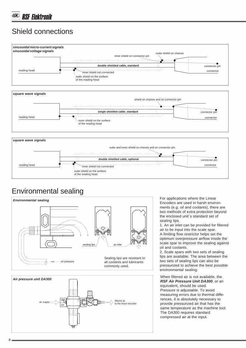
Environmental sealingFor applications where the LinearEncoders are used in harsh environ-ments (e.g. oil and coolants), there aretwo methods of extra protection beyondthe enclosed unit´s standard set ofsealing lips.1. An air inlet can be provided for filteredair to be input into the scale spar.A limiting flow restrictor helps set theoptimum overpressure airflow inside thescale spar to improve the sealing againstoil and coolants.2. Scale spars with two sets of sealinglips are available. The area between thetwo sets of sealing lips can also bepressurized to achieve the best possibleenvironmental sealing.
When filtered air is not available, theRSF Air Pressure Unit DA300, or anequivalent, should be used.Pressure is adjustable. To avoidmeasuring errors due to thermal diffe-rences, it is absolutely necessary toprovide pressurized air that has thesame temperature as the machine tool.The DA300 requires standardcompressed air at the input.
Environmental sealing
0
12
3
4
filtered airto the linear encoder
air supply
Shield connections
single shielded cable, standard
outer shield on the surfaceof the reading head
shield on chassis and on connector pin
reading head
connector pin
connector
double shielded cable, optional
inner shield not connected
outer shield on the surfaceof the reading head
outer and inner shield on chassis and on connector pin
reading head
connector pin
connector
double shielded cable, standard
inner shield on connector pin
inner shield not connected
outer shield on the surfaceof the reading head
outer shield on chassis
reading head
connector pin
connector
sinusoidal micro-current signals
square wave signals
sinusoidal voltage signals
square wave signals
Air pressure unit DA300
Sealing lips are resistant toall coolants and lubricantscommonly used.
9
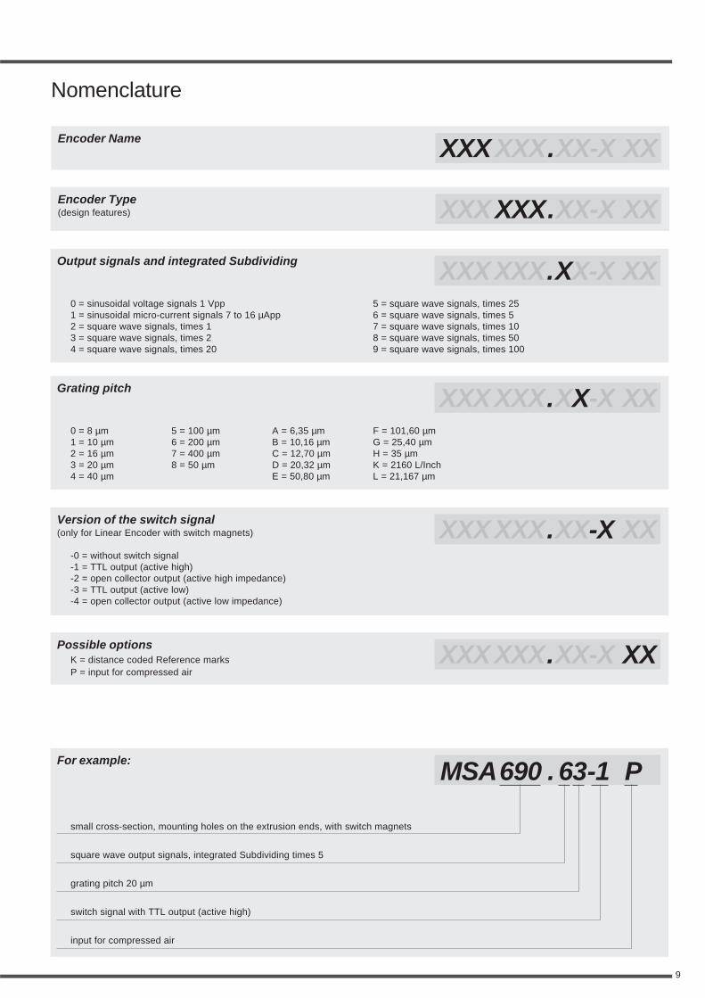
Encoder Name
Nomenclature
Possible optionsK = distance coded Reference marksP = input for compressed air
Version of the switch signal(only for Linear Encoder with switch magnets)
Grating pitch
Output signals and integrated Subdividing
Encoder Type(design features)
0 = sinusoidal voltage signals 1 Vpp1 = sinusoidal micro-current signals 7 to 16 µApp2 = square wave signals, times 13 = square wave signals, times 24 = square wave signals, times 20
0 = 8 µm1 = 10 µm2 = 16 µm3 = 20 µm4 = 40 µm
-0 = without switch signal-1 = TTL output (active high)-2 = open collector output (active high impedance)-3 = TTL output (active low)-4 = open collector output (active low impedance)
For example:
5 = square wave signals, times 256 = square wave signals, times 57 = square wave signals, times 108 = square wave signals, times 509 = square wave signals, times 100
5 = 100 µm6 = 200 µm7 = 400 µm8 = 50 µm
A = 6,35 µmB = 10,16 µmC = 12,70 µmD = 20,32 µmE = 50,80 µm
F = 101,60 µmG = 25,40 µmH = 35 µmK = 2160 L/InchL = 21,167 µm
XXX XXX.XX-X XX
XXX XXX.XX-X XX
XXX XXX.XX-X XX
XXX XXX.XX-X XX
XXX XXX.XX-X XX
XXX XXX.XX-X XX
MSA690 . 63-1 P
small cross-section, mounting holes on the extrusion ends, with switch magnets
square wave output signals, integrated Subdividing times 5
grating pitch 20 µm
switch signal with TTL output (active high)
input for compressed air
10
MSA 670 18-19
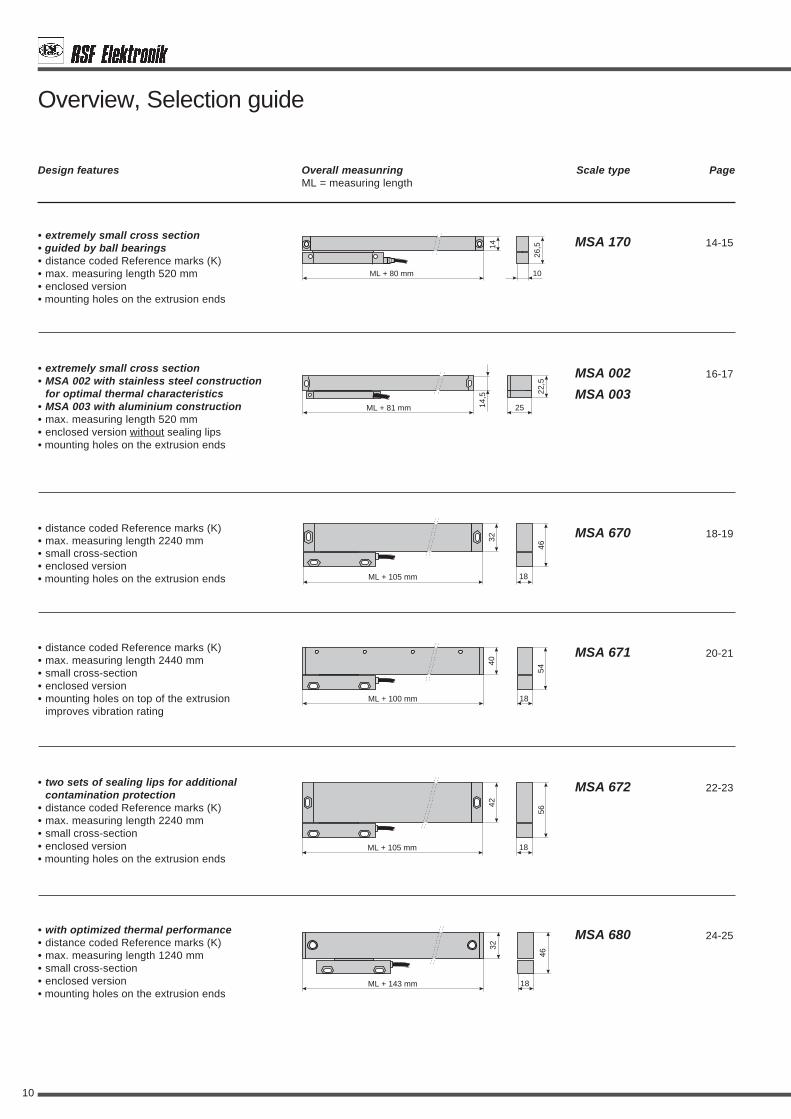
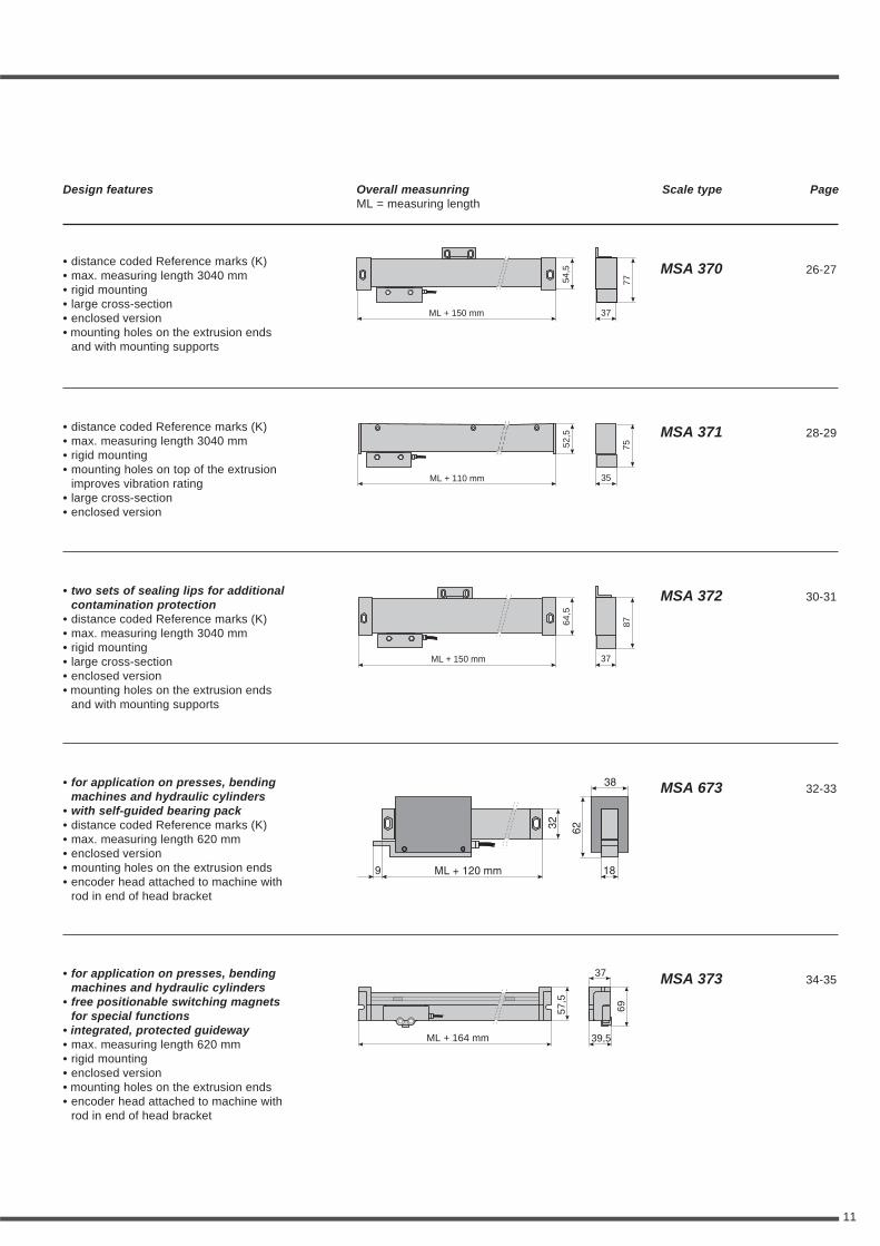
Design features Overall measunring Scale type PageML = measuring length
• distance coded Reference marks (K)• max. measuring length 2240 mm• small cross-section• enclosed version• mounting holes on the extrusion ends
• two sets of sealing lips for additionalcontamination protection
• distance coded Reference marks (K)• max. measuring length 2240 mm• small cross-section• enclosed version• mounting holes on the extrusion ends
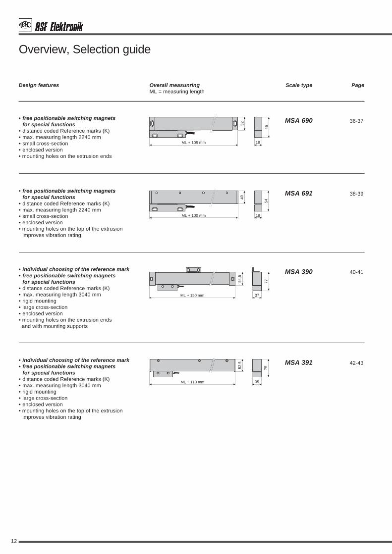
Overview, Selection guide
• distance coded Reference marks (K)• max. measuring length 2440 mm• small cross-section• enclosed version• mounting holes on top of the extrusion
improves vibration rating
18
46
32
ML + 105 mm
18
54
40
ML + 100 mm
18
56
42
ML + 105 mm
• with optimized thermal performance• distance coded Reference marks (K)• max. measuring length 1240 mm• small cross-section• enclosed version• mounting holes on the extrusion ends
18
46
32
ML + 143 mm
MSA 671 20-21
MSA 672 22-23
MSA 680 24-25
• extremely small cross section• guided by ball bearings• distance coded Reference marks (K)• max. measuring length 520 mm• enclosed version• mounting holes on the extrusion ends
10
26,514
ML + 80 mm
• extremely small cross section• MSA 002 with stainless steel construction
for optimal thermal characteristics• MSA 003 with aluminium construction• max. measuring length 520 mm• enclosed version without sealing lips• mounting holes on the extrusion ends
25
22,5
14,5
ML + 81 mm
MSA 170 14-15
MSA 002 16-17
MSA 003
11
Design features Overall measunring Scale type PageML = measuring length
• distance coded Reference marks (K)• max. measuring length 3040 mm• rigid mounting• large cross-section• enclosed version• mounting holes on the extrusion ends
and with mounting supports
• distance coded Reference marks (K)• max. measuring length 3040 mm• rigid mounting• mounting holes on top of the extrusion
improves vibration rating• large cross-section• enclosed version
37
7754,5
ML + 150 mm
35
7552,5
ML + 110 mm
MSA 370 26-27
MSA 371 28-29
• two sets of sealing lips for additionalcontamination protection
• distance coded Reference marks (K)• max. measuring length 3040 mm• rigid mounting• large cross-section• enclosed version• mounting holes on the extrusion ends
and with mounting supports
37
8764,5
ML + 150 mm
MSA 372 30-31
• for application on presses, bendingmachines and hydraulic cylinders
• with self-guided bearing pack• distance coded Reference marks (K)• max. measuring length 620 mm• enclosed version• mounting holes on the extrusion ends• encoder head attached to machine with
rod in end of head bracket
• for application on presses, bendingmachines and hydraulic cylinders
• free positionable switching magnetsfor special functions
• integrated, protected guideway• max. measuring length 620 mm• rigid mounting• enclosed version• mounting holes on the extrusion ends• encoder head attached to machine with
rod in end of head bracket
ML + 164 mm 39,5
6957,5
37
MSA 673 32-33
MSA 373 34-35
12
Overview, Selection guide
Design features Overall measunring Scale type PageML = measuring length
• free positionable switching magnetsfor special functions
• distance coded Reference marks (K)• max. measuring length 2240 mm• small cross-section• enclosed version• mounting holes on the extrusion ends
18
46
32
ML + 105 mm
MSA 690 36-37
MSA 691 38-39
MSA 391 42-43
MSA 390 40-41
• free positionable switching magnetsfor special functions
• distance coded Reference marks (K)• max. measuring length 2240 mm• small cross-section• enclosed version• mounting holes on the top of the extrusion
improves vibration rating
37
7754,5
ML + 150 mm
35
7552,5
ML + 110 mm
18
54
40
ML + 100 mm
• individual choosing of the reference mark• free positionable switching magnets
for special functions• distance coded Reference marks (K)• max. measuring length 3040 mm• rigid mounting• large cross-section• enclosed version• mounting holes on the extrusion ends and with mounting supports
• individual choosing of the reference mark• free positionable switching magnets
for special functions• distance coded Reference marks (K)• max. measuring length 3040 mm• rigid mounting• large cross-section• enclosed version• mounting holes on the top of the extrusion
improves vibration rating

13
Design features Overall measunring Scale type PageML = measuring length
• for retrofit of machine tools• high mounting tolerances• distance coded Reference marks (K)• max. measuring length 1740 mm• small cross-section• enclosed version• mounting holes on the extrusion ends
• for retrofit of machine tools• high mounting tolerances• distance coded Reference marks (K)• max. measuring length 3040 mm• rigid mounting• large cross-section• enclosed version• mounting holes on the extrusion ends
and with mounting supports
• for retrofit of machine tools• high mounting tolerances• with two sets of sealing lips• distance coded Reference marks (K)• max. measuring length 3040 mm• rigid mounting• large cross-section• enclosed version• mounting holes on the extrusion ends
and with mounting supports
• for retrofit of machine tools• high mounting tolerances• distance coded Reference marks (K)• max. measuring length 2240 mm• small cross-section• enclosed version• mounting holes on top of the extrusion
improves vibration rating
45
18ML + 105 mm
29
18
45
29
ML + 100 mm
32
77
54,5
ML + 150 mm
32
77
54,5
ML + 150 mm
MSA 650 46-47
MSA 651 48-49
MSA 350 50-51
MSA 352 52-53
14
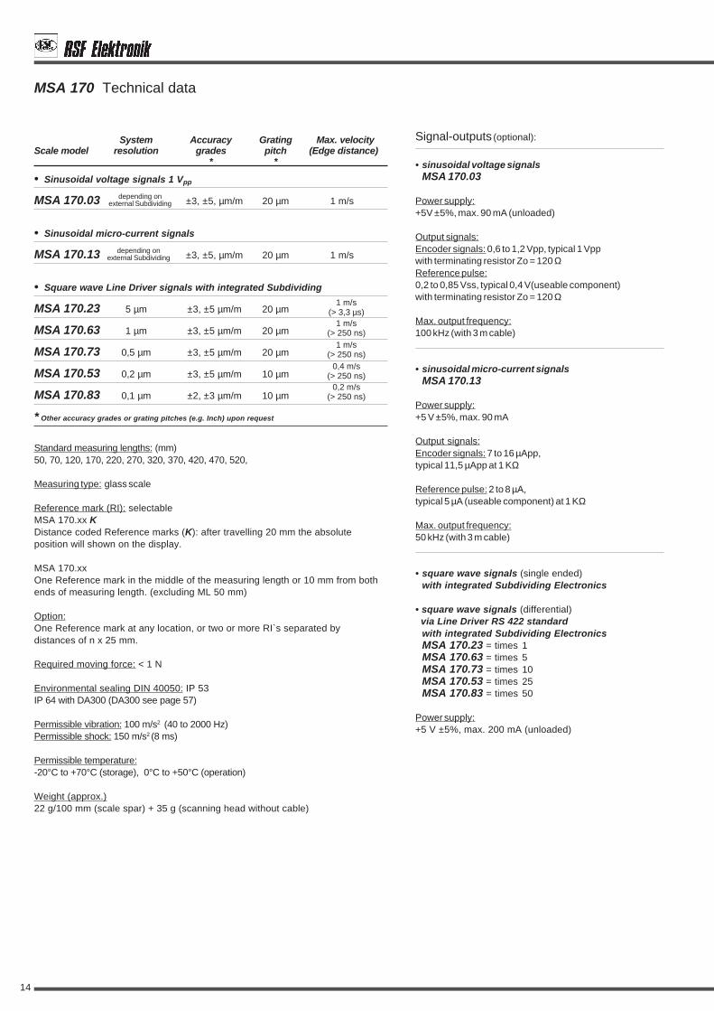
• Sinusoidal voltage signals 1 Vpp
MSA 170.03 ±3, ±5, µm/m 20 µm 1 m/s
• Sinusoidal micro-current signals
MSA 170.13 ±3, ±5, µm/m 20 µm 1 m/s
• Square wave Line Driver signals with integrated Subdividing
MSA 170.23 5 µm ±3, ±5 µm/m 20 µm
MSA 170.63 1 µm ±3, ±5 µm/m 20 µm
MSA 170.73 0,5 µm ±3, ±5 µm/m 20 µm
MSA 170.53 0,2 µm ±3, ±5 µm/m 10 µm
MSA 170.83 0,1 µm ±2, ±3 µm/m 10 µm
Signal-outputs (optional):
• sinusoidal voltage signalsMSA 170.03
Power supply:+5V ±5%, max. 90 mA (unloaded)
Output signals:Encoder signals: 0,6 to 1,2 Vpp, typical 1 Vppwith terminating resistor Zo = 120 ΩReference pulse:0,2 to 0,85 Vss, typical 0,4 V(useable component)with terminating resistor Zo = 120 Ω
Max. output frequency:100 kHz (with 3 m cable)
• sinusoidal micro-current signalsMSA 170.13
Power supply:+5 V ±5%, max. 90 mA
Output signals:Encoder signals: 7 to 16 µApp,typical 11,5 µApp at 1 KΩ
Reference pulse: 2 to 8 µA,typical 5 µA (useable component) at 1 KΩ
Max. output frequency:50 kHz (with 3 m cable)
• square wave signals (single ended)with integrated Subdividing Electronics
• square wave signals (differential) via Line Driver RS 422 standard
with integrated Subdividing ElectronicsMSA 170.23 = times 1MSA 170.63 = times 5MSA 170.73 = times 10MSA 170.53 = times 25MSA 170.83 = times 50
Power supply:+5 V ±5%, max. 200 mA (unloaded)
MSA 170 Technical data
Standard measuring lengths: (mm)50, 70, 120, 170, 220, 270, 320, 370, 420, 470, 520,
Measuring type: glass scale
Reference mark (RI): selectableMSA 170.xx KDistance coded Reference marks (K): after travelling 20 mm the absoluteposition will shown on the display.
MSA 170.xxOne Reference mark in the middle of the measuring length or 10 mm from bothends of measuring length. (excluding ML 50 mm)
Option:One Reference mark at any location, or two or more RI`s separated bydistances of n x 25 mm.
Required moving force: < 1 N
Environmental sealing DIN 40050: IP 53IP 64 with DA300 (DA300 see page 57)
Permissible vibration: 100 m/s2 (40 to 2000 Hz)Permissible shock: 150 m/s2 (8 ms)
Permissible temperature:-20°C to +70°C (storage), 0°C to +50°C (operation)
Weight (approx.)22 g/100 mm (scale spar) + 35 g (scanning head without cable)
* Other accuracy grades or grating pitches (e.g. Inch) upon request
System Accuracy Grating Max. velocityScale model resolution grades pitch (Edge distance)
* *
depending onexternal Subdividing
depending onexternal Subdividing
0,4 m/s(> 250 ns)
0,2 m/s(> 250 ns)
1 m/s(> 250 ns)
1 m/s(> 250 ns)
1 m/s(> 3,3 µs)

15
MSA 170 Dimensions - Mounting tolerances - Mounting possibilities:
overall length = measuring length + 80
measuring length
length of cable 3 m
air inlet M3 (both sides)
M = machine guideway
4
0±
0,2
4
3,4
10
19
26,5
14
0,5
±0,
2
3,4
10,5
6,5
M4
4
10
4
60 ±0,2
80
Ø6
3,4
0,1 M
0,1 M0,1 M
20 0,1 M20
12±
0,4
0,2 M
0 ±1
M3 / DIN 912
M4 / DIN 912
M3 / DIN 433 M3 / DIN 912

16
• Sinusoidal micro-current signals
MSA 002.13 ±3, ±5, ±10 µm/m 20 µm 2 m/s
MSA 002.11 ±3, ±2 µm/m 10 µm 1 m/s
• Square wave Line Driver signals with integrated Subdividing
MSA 002.63 1 µm ±3, ±5 µm/m 20 µm
MSA 002.73 0,5 µm ±3, ±5 µm/m 20 µm
MSA 002.71 0,25 µm ±2, ±3, ±5 µm/m 10 µm
MSA 002.51 0,1 µm ±2, ±3 µm/m 10 µm
• Sinusoidal micro-current signals
MSA 003.13 ±3, ±5, ±10 µm/m 20 µm 2 m/s
MSA 003.11 ±3, ±2 µm/m 10 µm 1 m/s
• Square wave Line Driver signals with integrated Subdividing
MSA 003.63 1 µm ±3, ±5 µm/m 20 µm
MSA 003.73 0,5 µm ±3, ±5 µm/m 20 µm
MSA 003.71 0,25 µm ±2, ±3, ±5 µm/m 10 µm
MSA 003.51 0,1 µm ±2, ±3 µm/m 10 µm
Signal-outputs (optional):
• sinusoidal micro-current signalsMSA 002.13MSA 002.11
MSA 003.13MSA 003.11
Power supply:+5 V ±5%, max. 120 mA
Output signals:Encoder signals: 7 to 16 µApp,typical 11,5 µApp at 1 KΩ
Reference pulse: 2 to 8 µA,typical 5 µA (useable component) at 1 KΩ
Max. output frequency:100 kHz (with 3 m cable)
• square wave signals (single ended)with integrated Subdividing Electronics
• square wave signals (differential) via Line Driver RS 422 standard
with integrated Subdividing ElectronicsMSA 002.63 = times 5MSA 002.73 = times 10MSA 002.71 = times 10MSA 002.51 = times 25
MSA 003.63 = times 5MSA 003.73 = times 10MSA 003.71 = times 10MSA 003.51 = times 25
Power supply:+5 V ±5%, max. 150 mA (unloaded)5 - 5,25 V, max. 150 mA (only for times 25, unloaded)
MSA 002, MSA 003 Technical data
MSA 002 with stainless steel construction for optimal thermal characteristicsMSA 003 with aluminium construction
MSA 002 and MSA 003 are without sealing lips
Standard measuring lengths: (mm)50, 70, 120, 170, 220, 270, 320, 370, 420, 470, 520
Measuring type: glass scale
Reference mark (RI):Standard:One Reference mark in the middle of the measuring length or 35 mm from bothends of measuring length.
Option:One Reference mark at any location, or two or more RI`s separated bydistances of n x 50 mm.
Required moving force: < 0,1 N
Permissible vibration: 30 m/s2 (40 to 2000 Hz)Permissible shock: 150 m/s2 (8 ms)
Permissible temperature: -20°C to +70°C (storage), 0°C to +50°C (operation)
Weight (approx.)70 g/100 mm (scale spar) + 25 g (scanning head without cable)
* Other accuracy grades or grating pitches (e.g. Inch) upon request
System Accuracy Grating Max. velocityScale model resolution grades pitch (Edge distance)
* *
depending onexternal Subdividing
depending onexternal Subdividing
0,45 m/s(> 200 ns)
1 m/s(> 600 ns)
1 m/s(> 300 ns)
1 m/s(> 300 ns)
0,45 m/s(> 200 ns)
1 m/s(> 600 ns)
1 m/s(> 300 ns)
1 m/s(> 300 ns)

17
sinusoidal micro-current signals
square wave signals
MSA 002 MSA 003 MSA 002 MSA 003
M = machine guideway
MSA 002, MSA 003 Dimensions - Mounting tolerances - Mounting possibilities:
18
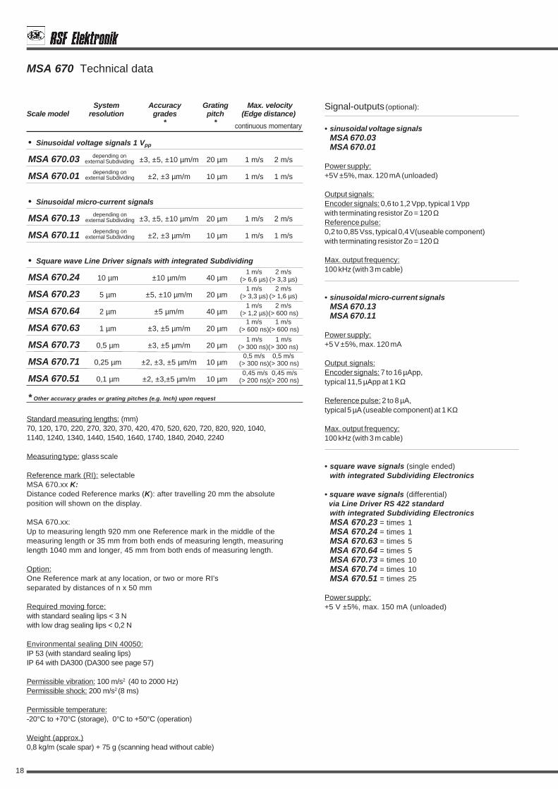
• Sinusoidal voltage signals 1 Vpp
MSA 670.03 ±3, ±5, ±10 µm/m 20 µm 1 m/s 2 m/s
MSA 670.01 ±2, ±3 µm/m 10 µm 1 m/s 1 m/s
• Sinusoidal micro-current signals
MSA 670.13 ±3, ±5, ±10 µm/m 20 µm 1 m/s 2 m/s
MSA 670.11 ±2, ±3 µm/m 10 µm 1 m/s 1 m/s
• Square wave Line Driver signals with integrated Subdividing
MSA 670.24 10 µm ±10 µm/m 40 µm
MSA 670.23 5 µm ±5, ±10 µm/m 20 µm
MSA 670.64 2 µm ±5 µm/m 40 µm
MSA 670.63 1 µm ±3, ±5 µm/m 20 µm
MSA 670.73 0,5 µm ±3, ±5 µm/m 20 µm
MSA 670.71 0,25 µm ±2, ±3, ±5 µm/m 10 µm
MSA 670.51 0,1 µm ±2, ±3,±5 µm/m 10 µm
Signal-outputs (optional):
• sinusoidal voltage signalsMSA 670.03MSA 670.01
Power supply:+5V ±5%, max. 120 mA (unloaded)
Output signals:Encoder signals: 0,6 to 1,2 Vpp, typical 1 Vppwith terminating resistor Zo = 120 ΩReference pulse:0,2 to 0,85 Vss, typical 0,4 V(useable component)with terminating resistor Zo = 120 Ω
Max. output frequency:100 kHz (with 3 m cable)
• sinusoidal micro-current signalsMSA 670.13MSA 670.11
Power supply:+5 V ±5%, max. 120 mA
Output signals:Encoder signals: 7 to 16 µApp,typical 11,5 µApp at 1 KΩ
Reference pulse: 2 to 8 µA,typical 5 µA (useable component) at 1 KΩ
Max. output frequency:100 kHz (with 3 m cable)
• square wave signals (single ended)with integrated Subdividing Electronics
• square wave signals (differential) via Line Driver RS 422 standard
with integrated Subdividing ElectronicsMSA 670.23 = times 1MSA 670.24 = times 1MSA 670.63 = times 5MSA 670.64 = times 5MSA 670.73 = times 10MSA 670.74 = times 10MSA 670.51 = times 25
Power supply:+5 V ±5%, max. 150 mA (unloaded)
MSA 670 Technical data
0,5 m/s 0,5 m/s(> 300 ns)(> 300 ns)
1 m/s 2 m/s(> 6,6 µs) (> 3,3 µs)
1 m/s 2 m/s(> 3,3 µs) (> 1,6 µs)
1 m/s 1 m/s(> 600 ns)(> 600 ns)
1 m/s 1 m/s(> 300 ns)(> 300 ns)
1 m/s 2 m/s(> 1,2 µs)(> 600 ns)
0,45 m/s 0,45 m/s(> 200 ns)(> 200 ns)
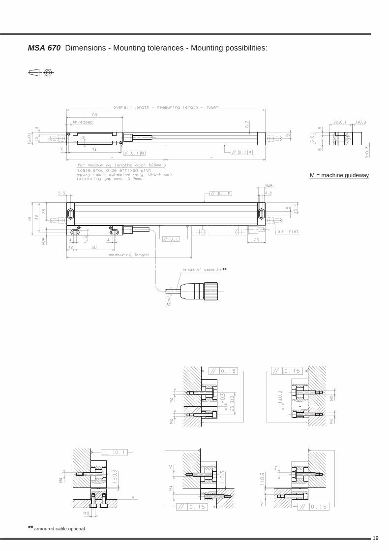
Standard measuring lengths: (mm)70, 120, 170, 220, 270, 320, 370, 420, 470, 520, 620, 720, 820, 920, 1040,1140, 1240, 1340, 1440, 1540, 1640, 1740, 1840, 2040, 2240
Measuring type: glass scale
Reference mark (RI): selectableMSA 670.xx K:Distance coded Reference marks (K): after travelling 20 mm the absoluteposition will shown on the display.
MSA 670.xx:Up to measuring length 920 mm one Reference mark in the middle of themeasuring length or 35 mm from both ends of measuring length, measuringlength 1040 mm and longer, 45 mm from both ends of measuring length.
Option:One Reference mark at any location, or two or more RI'sseparated by distances of n x 50 mm
Required moving force:with standard sealing lips < 3 Nwith low drag sealing lips < 0,2 N
Environmental sealing DIN 40050:IP 53 (with standard sealing lips)IP 64 with DA300 (DA300 see page 57)
Permissible vibration: 100 m/s2 (40 to 2000 Hz)Permissible shock: 200 m/s2 (8 ms)
Permissible temperature:-20°C to +70°C (storage), 0°C to +50°C (operation)
Weight (approx.)0,8 kg/m (scale spar) + 75 g (scanning head without cable)
* Other accuracy grades or grating pitches (e.g. Inch) upon request
System Accuracy Grating Max. velocityScale model resolution grades pitch (Edge distance)
* *
depending onexternal Subdividing
depending onexternal Subdividing
depending onexternal Subdividing
depending onexternal Subdividing
continuous momentary
19
MSA 670 Dimensions - Mounting tolerances - Mounting possibilities:
** armoured cable optional
M = machine guideway
**

20
• Sinusoidal voltage signals 1 Vpp
MSA 671.03 ±3, ±5, ±10 µm/m 20 µm 1 m/s 2 m/s
MSA 671.01 ±2, ±3 µm/m 10 µm 1 m/s 1 m/s
• Sinusoidal micro-current signals
MSA 671.13 ±3, ±5, ±10 µm/m 20 µm 1 m/s 2 m/s
MSA 671.11 ±2, ±3 µm/m 10 µm 1 m/s 1 m/s
• Square wave Line Driver signals with integrated Subdividing
MSA 671.24 10 µm ±10 µm/m 40 µm
MSA 671.23 5 µm ±5, ±10 µm/m 20 µm
MSA 671.64 2 µm ±5 µm/m 40 µm
MSA 671.63 1 µm ±3, ±5 µm/m 20 µm
MSA 671.73 0,5 µm ±3, ±5 µm/m 20 µm
MSA 671.71 0,25 µm ±2, ±3, ±5 µm/m 10 µm
MSA 671.51 0,1 µm ±2, ±3, ±5 µm/m 10 µm
Signal-outputs (optional):
• sinusoidal voltage signalsMSA 671.03MSA 671.01
Power supply:+5V ±5%, max. 120 mA (unloaded)
Output signals:Encoder signals: 0,6 to 1,2 Vpp, typical 1 Vppwith terminating resistor Zo = 120 ΩReference pulse:0,2 to 0,85 Vss, typical 0,4 V(useable component)with terminating resistor Zo = 120 Ω
Max. output frequency:100 kHz (with 3 m cable)
• sinusoidal micro-current signalsMSA 671.13MSA 671.11
Power supply:+5 V ±5%, max. 120 mA
Output signals:Encoder signals: 7 to 16 µApp,typical 11,5 µApp at 1 KΩ
Reference pulse: 2 to 8 µA,typical 5 µA (useable component) at 1 KΩ
Max. output frequency:100 kHz (with 3 m cable)
• square wave signals (single ended)with integrated Subdividing Electronics
• square wave signals (differential) via Line Driver RS 422 standard
with integrated Subdividing ElectronicsMSA 671.23 = times 1MSA 671.24 = times 1MSA 671.63 = times 5MSA 671.64 = times 5MSA 671.73 = times 10MSA 671.74 = times 10MSA 671.51 = times 25
Power supply:+5 V ±5%, max. 150 mA (unloaded)
MSA 671 Technical data
0,5 m/s 0,5 m/s(> 300 ns)(> 300 ns)
1 m/s 2 m/s(> 6,6 µs) (> 3,3 µs)
1 m/s 2 m/s(> 3,3 µs) (> 1,6 µs)
1 m/s 1 m/s(> 600 ns)(> 600 ns)
1 m/s 1 m/s(> 300 ns)(> 300 ns)
1 m/s 2 m/s(> 1,2 µs)(> 600 ns)
0,45 m/s 0,45 m/s(> 200 ns)(> 200 ns)
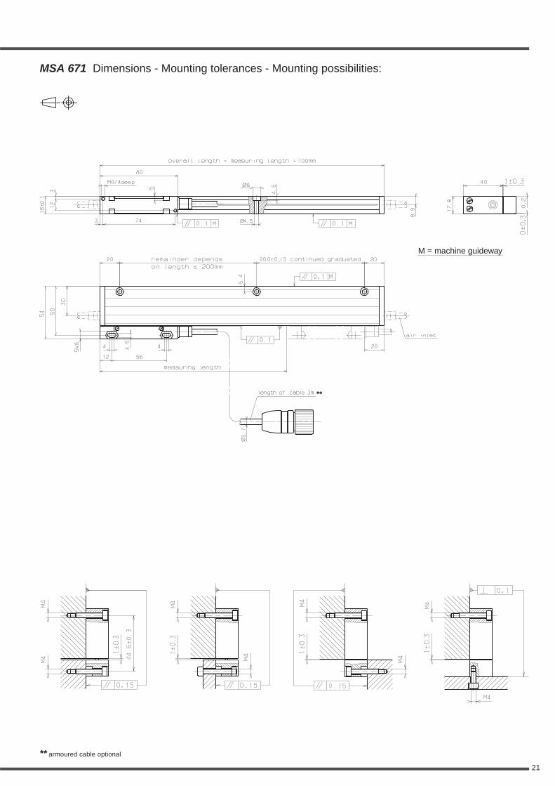
Standard measuring lengths: (mm)70, 120, 170, 220, 270, 320, 370, 420, 470, 520, 620, 720, 820, 920, 1040,1140, 1240, 1340, 1440, 1540, 1640, 1740, 1840, 2040, 2240
Measuring type: glass scale
Reference mark (RI): selectableMSA 671.xx K:Distance coded Reference marks (K): after travelling 20 mm the absoluteposition will shown on the display.
MSA 671.xx:Up to measuring length 920 mm one Reference mark in the middle of themeasuring length or 35 mm from both ends of measuring length, measuringlength 1040 mm and longer, 45 mm from both ends of measuring length.
Option:One Reference mark at any location, or two or more RI'sseparated by distances of n x 50 mm
Required moving force:with standard sealing lips < 3 Nwith low drag sealing lips < 0,2 N
Environmental sealing DIN 40050:IP 53 (with standard sealing lips)IP 64 with DA300 (DA300 see page 57)
Permissible vibration: 150 m/s2 (40 to 2000 Hz)Permissible shock: 300 m/s2 (8 ms)
Permissible temperature:-20°C to +70°C (storage), 0°C to +50°C (operation)
Weight (approx.)0,8 kg/m (scale spar) + 75 g (scanning head without cable)
* Other accuracy grades or grating pitches (e.g. Inch) upon request
System Accuracy Grating Max. velocityScale model resolution grades pitch (Edge distance)
* *
depending onexternal Subdividing
depending onexternal Subdividing
depending onexternal Subdividing
depending onexternal Subdividing
continuous momentary
21
** armoured cable optional
MSA 671 Dimensions - Mounting tolerances - Mounting possibilities:
M = machine guideway
**

22
• Sinusoidal voltage signals 1 Vpp
MSA 672.03 ±3, ±5, ±10 µm/m 20 µm 1 m/s 2 m/s
MSA 672.01 ±2, ±3 µm/m 10 µm 1 m/s 1 m/s
• Sinusoidal micro-current signals
MSA 672.13 ±3, ±5, ±10 µm/m 20 µm 1 m/s 2 m/s
MSA 672.11 ±2, ±3 µm/m 10 µm 1 m/s 1 m/s
• Square wave Line Driver signals with integrated Subdividing
MSA 672.24 10 µm ±10 µm/m 40 µm
MSA 672.23 5 µm ±5, ±10 µm/m 20 µm
MSA 672.64 2 µm ±5 µm/m 40 µm
MSA 672.63 1 µm ±3, ±5 µm/m 20 µm
MSA 672.73 0,5 µm ±3, ±5 µm/m 20 µm
MSA 672.71 0,25 µm ±2, ±3, ±5 µm/m 10 µm
MSA 672.51 0,1 µm ±2, ±3, ±5 µm/m 10 µm
Signal-outputs (optional):
• sinusoidal voltage signalsMSA 672.03MSA 672.01
Power supply:+5V ±5%, max. 120 mA (unloaded)
Output signals:Encoder signals: 0,6 to 1,2 Vpp, typical 1 Vppwith terminating resistor Zo = 120 ΩReference pulse:0,2 to 0,85 Vss, typical 0,4 V(useable component)with terminating resistor Zo = 120 Ω
Max. output frequency:100 kHz (with 3 m cable)
• sinusoidal micro-current signalsMSA 672.13MSA 672.11
Power supply:+5 V ±5%, max. 120 mA
Output signals:Encoder signals: 7 to 16 µApp,typical 11,5 µApp at 1 KΩ
Reference pulse: 2 to 8 µA,typical 5 µA (useable component) at 1 KΩ
Max. output frequency:100 kHz (with 3 m cable)
• square wave signals (single ended)with integrated Subdividing Electronics
• square wave signals (differential) via Line Driver RS 422 standard
with integrated Subdividing ElectronicsMSA 672.23 = times 1MSA 672.24 = times 1MSA 672.63 = times 5MSA 672.64 = times 5MSA 672.73 = times 10MSA 672.74 = times 10MSA 672.51 = times 25
Power supply:+5 V ±5%, max. 150 mA (unloaded)
MSA 672 Technical data
continuous momentary
0,5 m/s 0,5 m/s(> 300 ns)(> 300 ns)
1 m/s 2 m/s(> 6,6 µs) (> 3,3 µs)
1 m/s 2 m/s(> 3,3 µs) (> 1,6 µs)
1 m/s 1 m/s(> 600 ns)(> 600 ns)
1 m/s 1 m/s(> 300 ns)(> 300 ns)
1 m/s 2 m/s(> 1,2 µs)(> 600 ns)
0,45 m/s 0,45 m/s(> 200 ns)(> 200 ns)
Standard measuring lengths: (mm)70, 120, 170, 220, 270, 320, 370, 420, 470, 520, 620, 720, 820, 920, 1040,1140, 1240, 1340, 1440, 1540, 1640, 1740, 1840, 2040, 2240
Measuring type: glass scale
Reference mark (RI): selectableMSA 672.xx K:Distance coded Reference marks (K): after travelling 20 mm the absoluteposition will shown on the display.
MSA 672.xx:Up to measuring length 920 mm one Reference mark in the middle of themeasuring length or 35 mm from both ends of measuring length, measuringlength 1040 mm and longer, 45 mm from both ends of measuring length.
Option:One Reference mark at any location, or two or more RI'sseparated by distances of n x 50 mm
Required moving force:< 6 N (two set of sealing lips)
Environmental sealing DIN 40050:IP 54 (two set of sealing lips)IP 64 with DA300 (DA300 see page 57)
Permissible vibration: 150 m/s2 (40 to 2000 Hz)Permissible shock: 300 m/s2 (8 ms)
Permissible temperature:-20°C to +70°C (storage), 0°C to +50°C (operation)
Weight (approx.)0,8 kg/m (scale spar) + 80 g (scanning head without cable)
* Other accuracy grades or grating pitches (e.g. Inch) upon request
System Accuracy Grating Max. velocityScale model resolution grades pitch (Edge distance)
* *
depending onexternal Subdividing
depending onexternal Subdividing
depending onexternal Subdividing
depending onexternal Subdividing

23
** armoured cable optional
MSA 672 Dimensions - Mounting tolerances - Mounting possibilities:
M = machine guideway
**

24
• Sinusoidal voltage signals 1 Vpp
MSA 680.03 ±3, ±5 µm/m 20 µm 1 m/s 2 m/s
MSA 680.01 ±2, ±3 µm/m 10 µm 1 m/s 1 m/s
• Sinusoidal micro-current signals
MSA 680.13 ±3, ±5 µm/m 20 µm 1 m/s 2 m/s
MSA 680.11 ±2, ±3 µm/m 10 µm 1 m/s 1 m/s
• Square wave Line Driver signals with integrated Subdividing
MSA 680.23 5 µm ±5 µm/m 20 µm
MSA 680.64 2 µm ±5 µm/m 40 µm
MSA 680.63 1 µm ±3, ±5 µm/m 20 µm
MSA 680.73 0,5 µm ±3, ±5 µm/m 20 µm
MSA 680.71 0,25 µm ±2, ±3, ±5 µm/m 10 µm
MSA 680.51 0,1 µm ±2, ±3, ±5 µm/m 10 µm
Signal-outputs (optional):
• sinusoidal voltage signalsMSA 680.03MSA 680.01
Power supply:+5V ±5%, max. 120 mA (unloaded)
Output signals:Encoder signals: 0,6 to 1,2 Vpp, typical 1 Vppwith terminating resistor Zo = 120 ΩReference pulse:0,2 to 0,85 Vss, typical 0,4 V(useable component)with terminating resistor Zo = 120 Ω
Max. output frequency:100 kHz (with 3 m cable)
• sinusoidal micro-current signalsMSA 680.13MSA 680.11
Power supply:+5 V ±5%, max. 120 mA
Output signals:Encoder signals: 7 to 16 µApp,typical 11,5 µApp at 1 KΩ
Reference pulse: 2 to 8 µA,typical 5 µA (useable component) at 1 KΩ
Max. output frequency:100 kHz (with 3 m cable)
• square wave signals (single ended)with integrated Subdividing Electronics
• square wave signals (differential) via Line Driver RS 422 standard
with integrated Subdividing ElectronicsMSA 680.23 = times 1MSA 680.63 = times 5MSA 680.64 = times 5MSA 680.73 = times 10MSA 680.74 = times 10MSA 680.51 = times 25
Power supply:+5 V ±5%, max. 150 mA (unloaded)
MSA 680 Technical data
continuous momentary
0,5 m/s 0,5 m/s(> 300 ns)(> 300 ns)
1 m/s 2 m/s(> 3,3 µs) (> 1,6 µs)
1 m/s 1 m/s(> 600 ns)(> 600 ns)
1 m/s 1 m/s(> 300 ns)(> 300 ns)
1 m/s 2 m/s(> 1,2 µs)(> 600 ns)
0,45 m/s 0,45 m/s(> 200 ns)(> 200 ns)
Standard measuring lengths: (mm)70, 120, 170, 220, 270, 320, 370, 420, 470, 520, 620, 720, 820, 920, 1040, 1140, 1240
Measuring type: glass scale
Reference mark (RI): selectableMSA 680.xx K:Distance coded Reference marks (K): after travelling 20 mm the absoluteposition will shown on the display.
MSA 680.xx:Up to measuring length 920 mm one Reference mark in the middle of themeasuring length or 35 mm from both ends of measuring length, measuringlength 1040 mm and longer, 45 mm from both ends of measuring length.
Option:One Reference mark at any location, or two or more RI'sseparated by distances of n x 50 mm
Required moving force:with standard sealing lips < 3 Nwith low drag sealing lips < 0,2 N
Environmental sealing DIN 40050:IP 53 (with standard sealing lips)IP 64 with DA300 (DA300 see page 57)
Permissible vibration: 100 m/s2 (40 to 2000 Hz)Permissible shock: 200 m/s2 (8 ms)
Permissible temperature:-20°C to +70°C (storage), 0°C to +50°C (operation)
Weight (approx.)0,8 kg/m (scale spar) + 75 g (scanning head without cable)
* Other accuracy grades or grating pitches (e.g. Inch) upon request
System Accuracy Grating Max. velocityScale model resolution grades pitch (Edge distance)
* *
depending onexternal Subdividing
depending onexternal Subdividing
depending onexternal Subdividing
depending onexternal Subdividing

25
** armoured cable optional
MSA 680 Dimensions - Mounting tolerances - Mounting possibilities:
M = machine guideway
**

26
• Sinusoidal voltage signals 1 Vpp
MSA 370.03 ±3, ±5, ±10 µm/m 20 µm 1 m/s 2 m/s
MSA 370.01 ±2, ±3 µm/m 10 µm 1 m/s 1 m/s
• Sinusoidal micro-current signals
MSA 370.13 ±3, ±5, ±10 µm/m 20 µm 1 m/s 2 m/s
MSA 370.11 ±2, ±3 µm/m 10 µm 1 m/s 1 m/s
• Square wave Line Driver signals with integrated Subdividing
MSA 370.24 10 µm ±10 µm/m 40 µm
MSA 370.23 5 µm ±5, ±10 µm/m 20 µm
MSA 370.64 2 µm ±5 µm/m 40 µm
MSA 370.63 1 µm ±3, ±5 µm/m 20 µm
MSA 370.73 0,5 µm ±3, ±5 µm/m 20 µm
MSA 370.71 0,25 µm ±2, ±3, ±5 µm/m 10 µm
MSA 370.51 0,1 µm ±2, ±3, ±5 µm/m 10 µm
Signal-outputs (optional):
• sinusoidal voltage signalsMSA 370.03MSA 370.01
Power supply:+5V ±5%, max. 120 mA (unloaded)
Output signals:Encoder signals: 0,6 to 1,2 Vpp, typical 1 Vppwith terminating resistor Zo = 120 ΩReference pulse:0,2 to 0,85 Vss, typical 0,4 V (useable component)with terminating resistor Zo = 120 Ω
Max. output frequency:100 kHz (with 3 m cable)
• sinusoidal micro-current signalsMSA 370.13MSA 370.11
Power supply:+5 V ±5%, max. 120 mA
Output signals:Encoder signals: 7 to 16 µApp,typical 11,5 µApp at 1 KΩ
Reference pulse: 2 to 8 µA,typical 5 µA (useable component) at 1 KΩ
Max. output frequency:100 kHz (with 3 m cable)
• square wave signals (single ended)with integrated Subdividing Electronics
• square wave signals (differential) via Line Driver RS 422 standard
with integrated Subdividing ElectronicsMSA 370.23 = times 1MSA 370.24 = times 1MSA 370.63 = times 5MSA 370.64 = times 5MSA 370.73 = times 10MSA 370.74 = times 10MSA 370.51 = times 25
Power supply:+5 V ±5%, max. 150 mA (unloaded)
MSA 370 Technical data
0,5 m/s 0,5 m/s(> 300 ns)(> 300 ns)
1 m/s 2 m/s(> 6,6 µs) (> 3,3 µs)
1 m/s 2 m/s(> 3,3 µs) (> 1,6 µs)
1 m/s 1 m/s(> 600 ns)(> 600 ns)
1 m/s 1 m/s(> 300 ns)(> 300 ns)
1 m/s 2 m/s(> 1,2 µs)(> 600 ns)
0,45 m/s 0,45 m/s(> 200 ns)(> 200 ns)
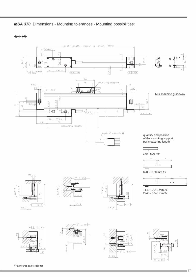
Standard measuring lengths: (mm)170, 220, 270, 320, 370, 420, 470, 520, 620, 720, 770, 820, 920, 1040, 1140, 1240,1340, 1440, 1540, 1640, 1740, 1840, 2040, 2240, 2440, 2640, 2840, 3040
Measuring type: glass scale
Reference mark (RI): selectableMSA 370.xx K:Distance coded Reference marks (K): after travelling 20 mm the absoluteposition will shown on the display.
MSA 370.xx:Up to measuring length 920 mm one Reference mark in the middle of themeasuring length or 35 mm from both ends of measuring length, measuringlength 1040 mm and longer, 45 mm from both ends of measuring length.
Option:One Reference mark at any location, or two or more RI's separatedby distances of n x 50 mm
Required moving force:with standard sealing lips < 3 Nwith low drag sealing lips < 0,2 N
Environmental sealing DIN 40050:IP 53 (with standard sealing lips)IP 64 with DA300 (DA300 see page 57)
Permissible vibration: 150 m/s2 (40 to 2000 Hz)Permissible shock: 300 m/s2 (8 ms)
Permissible temperature:-20°C to +70°C (storage), 0°C to +50°C (operation)
Weight (approx.)3 kg/m (scale spar) + 245 g (scanning head without cable)
* Other accuracy grades or grating pitches (e.g. Inch) upon request
System Accuracy Grating Max. velocityScale model resolution grades pitch (Edge distance)
* *
depending onexternal Subdividing
depending onexternal Subdividing
depending onexternal Subdividing
depending onexternal Subdividing
continuous momentary
27
** armoured cable optional
MSA 370 Dimensions - Mounting tolerances - Mounting possibilities:
M = machine guideway
**quantity and positionof the mounting supportper measuring length
170 - 520 mm
620 - 1020 mm 1x
1140 - 2040 mm 2x2240 - 3040 mm 3x
28
• Sinusoidal voltage signals 1 Vpp
MSA 371.03 ±3, ±5, ±10 µm/m 20 µm 1 m/s 2 m/s
MSA 371.01 ±2, ±3 µm/m 10 µm 1 m/s 1 m/s
• Sinusoidal micro-current signals
MSA 371.13 ±3, ±5, ±10 µm/m 20 µm 1 m/s 2 m/s
MSA 371.11 ±2, ±3 µm/m 10 µm 1 m/s 1 m/s
• Square wave Line Driver signals with integrated Subdividing
MSA 371.24 10 µm ±10 µm/m 40 µm
MSA 371.23 5 µm ±5, ±10 µm/m 20 µm
MSA 371.64 2 µm ±5 µm/m 40 µm
MSA 371.63 1 µm ±3, ±5 µm/m 20 µm
MSA 371.73 0,5 µm ±3, ±5 µm/m 20 µm
MSA 371.71 0,25 µm ±2, ±3, ±5 µm/m 10 µm
MSA 371.51 0,1 µm ±2, ±3, ±5 µm/m 10 µm
Signal-outputs (optional):
• sinusoidal voltage signalsMSA 371.03MSA 371.01
Power supply:+5V ±5%, max. 120 mA (unloaded)
Output signals:Encoder signals: 0,6 to 1,2 Vpp, typical 1 Vppwith terminating resistor Zo = 120 ΩReference pulse:0,2 to 0,85 Vss, typical 0,4 V(useable component)with terminating resistor Zo = 120 Ω
Max. output frequency:100 kHz (with 3 m cable)
• sinusoidal micro-current signalsMSA 371.13MSA 371.11
Power supply:+5 V ±5%, max. 120 mA
Output signals:Encoder signals: 7 to 16 µApp,typical 11,5 µApp at 1 KΩ
Reference pulse: 2 to 8 µA,typical 5 µA (useable component) at 1 KΩ
Max. output frequency:100 kHz (with 3 m cable)
• square wave signals (single ended)with integrated Subdividing Electronics
• square wave signals (differential) via Line Driver RS 422 standard
with integrated Subdividing ElectronicsMSA 371.23 = times 1MSA 371.24 = times 1MSA 371.63 = times 5MSA 371.64 = times 5MSA 371.73 = times 10MSA 371.74 = times 10MSA 371.51 = times 25
Power supply:+5 V ±5%, max. 150 mA (unloaded)
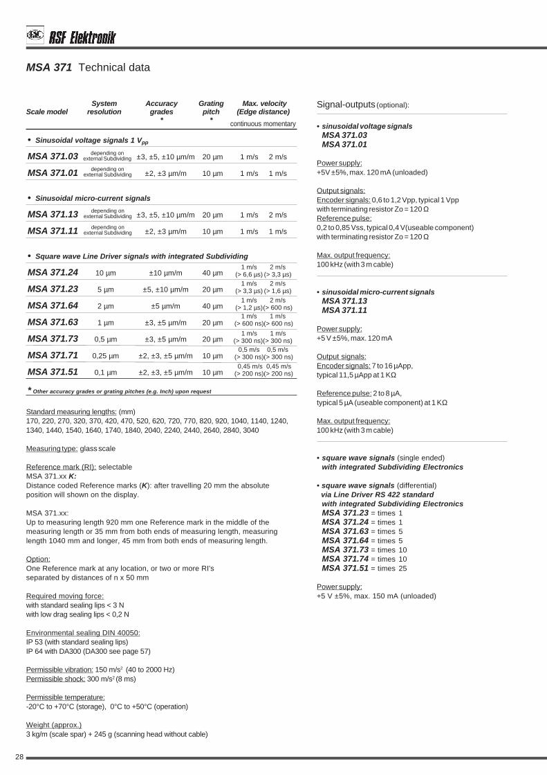
MSA 371 Technical data
0,5 m/s 0,5 m/s(> 300 ns)(> 300 ns)
1 m/s 2 m/s(> 6,6 µs) (> 3,3 µs)
1 m/s 2 m/s(> 3,3 µs) (> 1,6 µs)
1 m/s 1 m/s(> 600 ns)(> 600 ns)
1 m/s 1 m/s(> 300 ns)(> 300 ns)
1 m/s 2 m/s(> 1,2 µs)(> 600 ns)
0,45 m/s 0,45 m/s(> 200 ns)(> 200 ns)
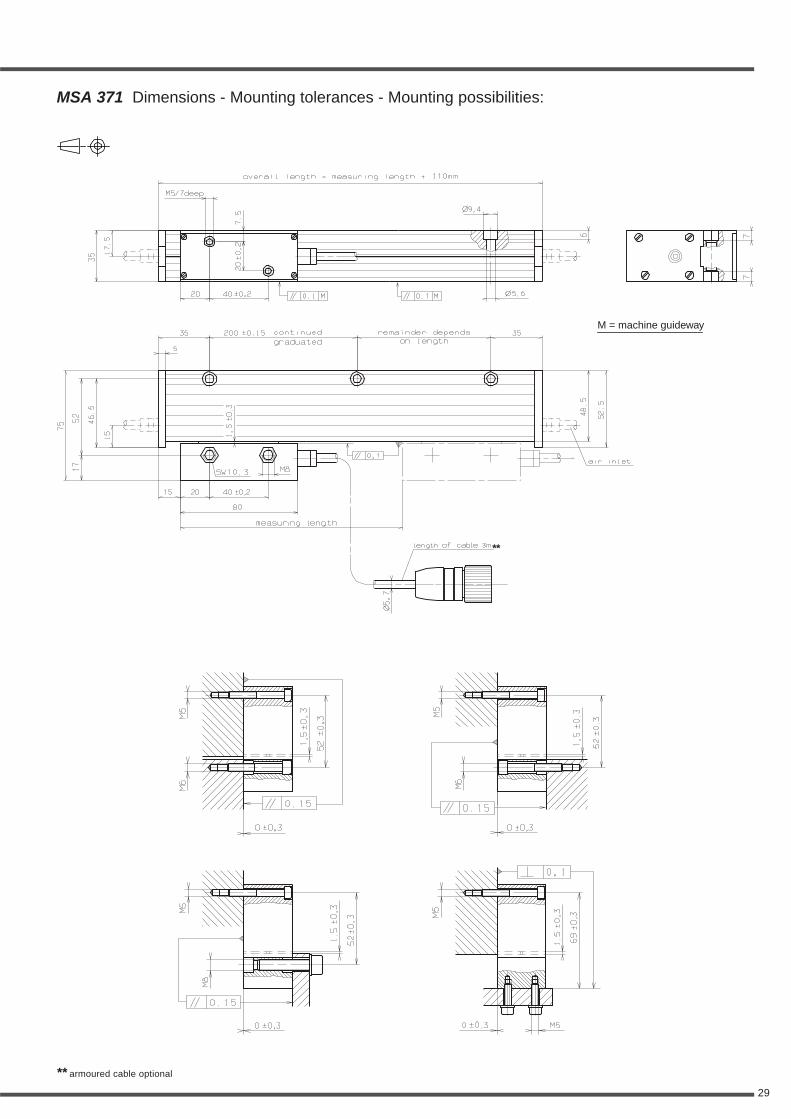
Standard measuring lengths: (mm)170, 220, 270, 320, 370, 420, 470, 520, 620, 720, 770, 820, 920, 1040, 1140, 1240,1340, 1440, 1540, 1640, 1740, 1840, 2040, 2240, 2440, 2640, 2840, 3040
Measuring type: glass scale
Reference mark (RI): selectableMSA 371.xx K:Distance coded Reference marks (K): after travelling 20 mm the absoluteposition will shown on the display.
MSA 371.xx:Up to measuring length 920 mm one Reference mark in the middle of themeasuring length or 35 mm from both ends of measuring length, measuringlength 1040 mm and longer, 45 mm from both ends of measuring length.
Option:One Reference mark at any location, or two or more RI'sseparated by distances of n x 50 mm
Required moving force:with standard sealing lips < 3 Nwith low drag sealing lips < 0,2 N
Environmental sealing DIN 40050:IP 53 (with standard sealing lips)IP 64 with DA300 (DA300 see page 57)
Permissible vibration: 150 m/s2 (40 to 2000 Hz)Permissible shock: 300 m/s2 (8 ms)
Permissible temperature:-20°C to +70°C (storage), 0°C to +50°C (operation)
Weight (approx.)3 kg/m (scale spar) + 245 g (scanning head without cable)
* Other accuracy grades or grating pitches (e.g. Inch) upon request
System Accuracy Grating Max. velocityScale model resolution grades pitch (Edge distance)
* *
depending onexternal Subdividing
depending onexternal Subdividing
depending onexternal Subdividing
depending onexternal Subdividing
continuous momentary
29
MSA 371 Dimensions - Mounting tolerances - Mounting possibilities:
** armoured cable optional
M = machine guideway
**
30
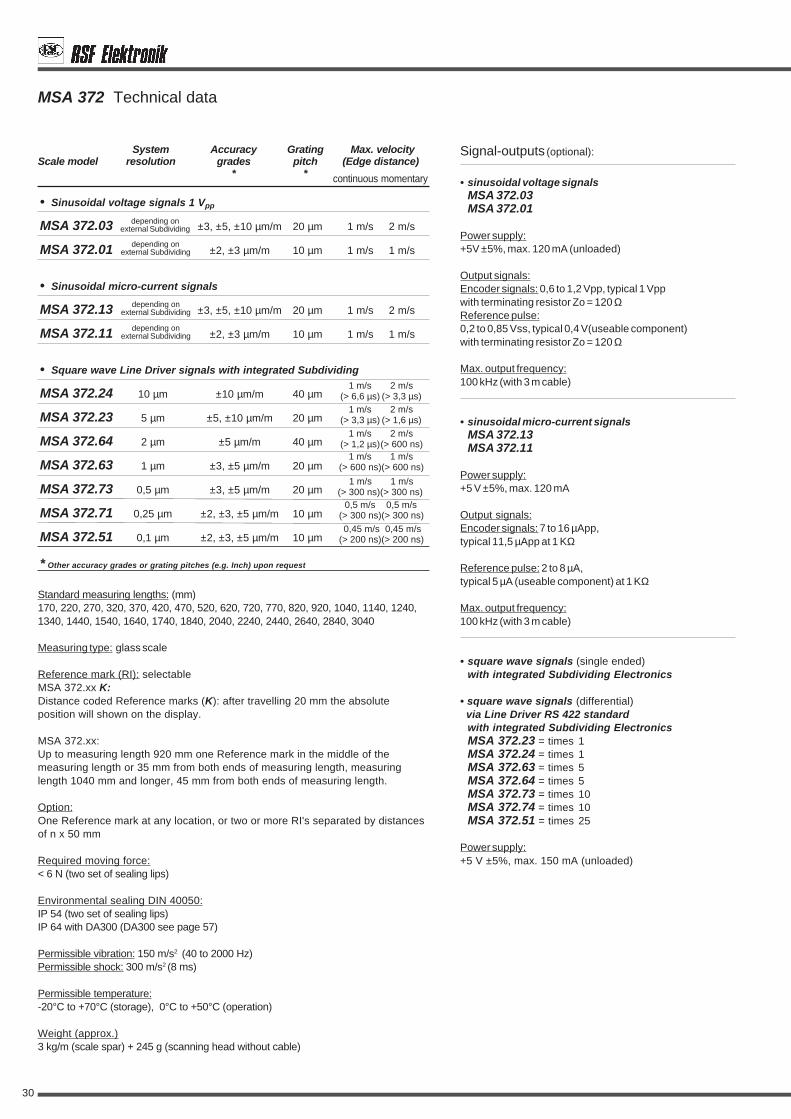
• Sinusoidal voltage signals 1 Vpp
MSA 372.03 ±3, ±5, ±10 µm/m 20 µm 1 m/s 2 m/s
MSA 372.01 ±2, ±3 µm/m 10 µm 1 m/s 1 m/s
• Sinusoidal micro-current signals
MSA 372.13 ±3, ±5, ±10 µm/m 20 µm 1 m/s 2 m/s
MSA 372.11 ±2, ±3 µm/m 10 µm 1 m/s 1 m/s
• Square wave Line Driver signals with integrated Subdividing
MSA 372.24 10 µm ±10 µm/m 40 µm
MSA 372.23 5 µm ±5, ±10 µm/m 20 µm
MSA 372.64 2 µm ±5 µm/m 40 µm
MSA 372.63 1 µm ±3, ±5 µm/m 20 µm
MSA 372.73 0,5 µm ±3, ±5 µm/m 20 µm
MSA 372.71 0,25 µm ±2, ±3, ±5 µm/m 10 µm
MSA 372.51 0,1 µm ±2, ±3, ±5 µm/m 10 µm
Signal-outputs (optional):
• sinusoidal voltage signalsMSA 372.03MSA 372.01
Power supply:+5V ±5%, max. 120 mA (unloaded)
Output signals:Encoder signals: 0,6 to 1,2 Vpp, typical 1 Vppwith terminating resistor Zo = 120 ΩReference pulse:0,2 to 0,85 Vss, typical 0,4 V(useable component)with terminating resistor Zo = 120 Ω
Max. output frequency:100 kHz (with 3 m cable)
• sinusoidal micro-current signalsMSA 372.13MSA 372.11
Power supply:+5 V ±5%, max. 120 mA
Output signals:Encoder signals: 7 to 16 µApp,typical 11,5 µApp at 1 KΩ
Reference pulse: 2 to 8 µA,typical 5 µA (useable component) at 1 KΩ
Max. output frequency:100 kHz (with 3 m cable)
• square wave signals (single ended)with integrated Subdividing Electronics
• square wave signals (differential) via Line Driver RS 422 standard
with integrated Subdividing ElectronicsMSA 372.23 = times 1MSA 372.24 = times 1MSA 372.63 = times 5MSA 372.64 = times 5MSA 372.73 = times 10MSA 372.74 = times 10MSA 372.51 = times 25
Power supply:+5 V ±5%, max. 150 mA (unloaded)
MSA 372 Technical data
continuous momentary
0,5 m/s 0,5 m/s(> 300 ns)(> 300 ns)
1 m/s 2 m/s(> 6,6 µs) (> 3,3 µs)
1 m/s 2 m/s(> 3,3 µs) (> 1,6 µs)
1 m/s 1 m/s(> 600 ns)(> 600 ns)
1 m/s 1 m/s(> 300 ns)(> 300 ns)
1 m/s 2 m/s(> 1,2 µs)(> 600 ns)
0,45 m/s 0,45 m/s(> 200 ns)(> 200 ns)
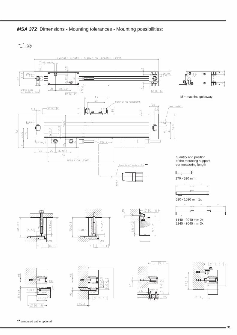
Standard measuring lengths: (mm)170, 220, 270, 320, 370, 420, 470, 520, 620, 720, 770, 820, 920, 1040, 1140, 1240,1340, 1440, 1540, 1640, 1740, 1840, 2040, 2240, 2440, 2640, 2840, 3040
Measuring type: glass scale
Reference mark (RI): selectableMSA 372.xx K:Distance coded Reference marks (K): after travelling 20 mm the absoluteposition will shown on the display.
MSA 372.xx:Up to measuring length 920 mm one Reference mark in the middle of themeasuring length or 35 mm from both ends of measuring length, measuringlength 1040 mm and longer, 45 mm from both ends of measuring length.
Option:One Reference mark at any location, or two or more RI's separated by distancesof n x 50 mm
Required moving force:< 6 N (two set of sealing lips)
Environmental sealing DIN 40050:IP 54 (two set of sealing lips)IP 64 with DA300 (DA300 see page 57)
Permissible vibration: 150 m/s2 (40 to 2000 Hz)Permissible shock: 300 m/s2 (8 ms)
Permissible temperature:-20°C to +70°C (storage), 0°C to +50°C (operation)
Weight (approx.)3 kg/m (scale spar) + 245 g (scanning head without cable)
* Other accuracy grades or grating pitches (e.g. Inch) upon request
System Accuracy Grating Max. velocityScale model resolution grades pitch (Edge distance)
* *
depending onexternal Subdividing
depending onexternal Subdividing
depending onexternal Subdividing
depending onexternal Subdividing
31
** armoured cable optional
MSA 372 Dimensions - Mounting tolerances - Mounting possibilities:
M = machine guideway
**
quantity and positionof the mounting supportper measuring length
170 - 520 mm
620 - 1020 mm 1x
1140 - 2040 mm 2x2240 - 3040 mm 3x
32
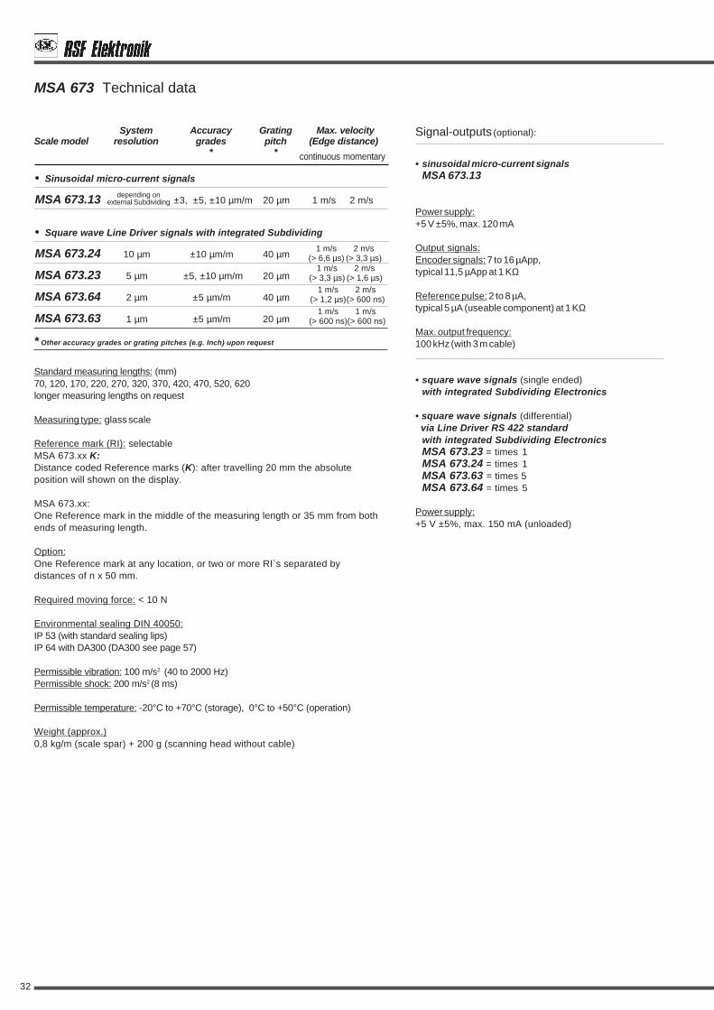
• Sinusoidal micro-current signals
MSA 673.13 ±3, ±5, ±10 µm/m 20 µm 1 m/s 2 m/s
• Square wave Line Driver signals with integrated Subdividing
MSA 673.24 10 µm ±10 µm/m 40 µm
MSA 673.23 5 µm ±5, ±10 µm/m 20 µm
MSA 673.64 2 µm ±5 µm/m 40 µm
MSA 673.63 1 µm ±5 µm/m 20 µm
MSA 673 Technical data
Signal-outputs (optional):
• sinusoidal micro-current signalsMSA 673.13
Power supply:+5 V ±5%, max. 120 mA
Output signals:Encoder signals: 7 to 16 µApp,typical 11,5 µApp at 1 KΩ
Reference pulse: 2 to 8 µA,typical 5 µA (useable component) at 1 KΩ
Max. output frequency:100 kHz (with 3 m cable)
• square wave signals (single ended)with integrated Subdividing Electronics
• square wave signals (differential) via Line Driver RS 422 standard
with integrated Subdividing ElectronicsMSA 673.23 = times 1MSA 673.24 = times 1MSA 673.63 = times 5MSA 673.64 = times 5
Power supply:+5 V ±5%, max. 150 mA (unloaded)
continuous momentary
Standard measuring lengths: (mm)70, 120, 170, 220, 270, 320, 370, 420, 470, 520, 620longer measuring lengths on request
Measuring type: glass scale
Reference mark (RI): selectableMSA 673.xx K:Distance coded Reference marks (K): after travelling 20 mm the absoluteposition will shown on the display.
MSA 673.xx:One Reference mark in the middle of the measuring length or 35 mm from bothends of measuring length.
Option:One Reference mark at any location, or two or more RI`s separated bydistances of n x 50 mm.
Required moving force: < 10 N
Environmental sealing DIN 40050:IP 53 (with standard sealing lips)IP 64 with DA300 (DA300 see page 57)
Permissible vibration: 100 m/s2 (40 to 2000 Hz)Permissible shock: 200 m/s2 (8 ms)
Permissible temperature: -20°C to +70°C (storage), 0°C to +50°C (operation)
Weight (approx.)0,8 kg/m (scale spar) + 200 g (scanning head without cable)
* Other accuracy grades or grating pitches (e.g. Inch) upon request
System Accuracy Grating Max. velocityScale model resolution grades pitch (Edge distance)
* *
depending onexternal Subdividing
1 m/s 2 m/s(> 6,6 µs) (> 3,3 µs)
1 m/s 1 m/s(> 600 ns)(> 600 ns)
1 m/s 2 m/s(> 3,3 µs) (> 1,6 µs)
1 m/s 2 m/s(> 1,2 µs)(> 600 ns)
33
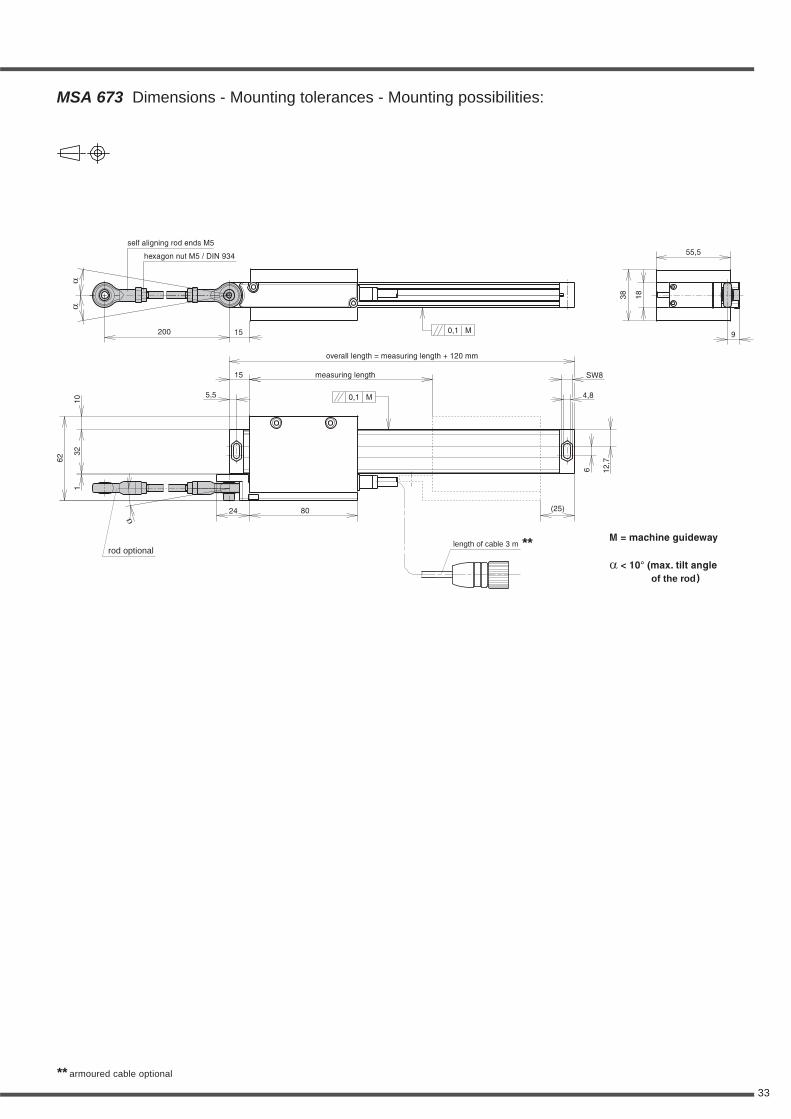
rod optional
of the rod
length of cable 3 m
MSA 673 Dimensions - Mounting tolerances - Mounting possibilities:
** armoured cable optional
**

34
• Square wave Line Driver signals with integrated Subdividing
MSA 373.65 5 µm ±5, ±10 µm/m 100 µm
MSA 373.55 1 µm ±5, ±10 µm/m 100 µm
MSA 373 Technical data
Signal-outputs (optional):
• square wave signals (single ended)with integrated Subdividing Electronics
• square wave signals (differential) via Line Driver RS 422 standard
with integrated Subdividing ElectronicsMSA 373.65 = times 5MSA 373.55 = times 25
Power supply:+5 V ±5%, max. 150 mA (unloaded)
continuous momentary
Standard measuring lengths: (mm)70, 120, 170, 220, 270, 320, 370, 420, 470, 520, 620(longer measuring lengths on request)
Measuring type: glass scale
Free positionable switching magnets for special functions:The position of the 2 switch points (S1 and S2) within the measuring lengthcan be select by the customer (details on page 44 and 45)
Reference mark (RI):Standard:One Reference mark in the middle of the measuring length or 35 mm from bothends of measuring length.
Option:One Reference mark at any location, or two or more RI`s separated bydistances of n x 50 mm.
Required moving force: < 5 N
Environmental sealing DIN 40050:IP 53 (with standard sealing lips)IP 64 with DA300 (DA300 see page 57)
Permissible vibration: 150 m/s2 (40 to 2000 Hz)Permissible shock: 300 m/s2 (8 ms)
Permissible temperature: -20°C to +70°C (storage), 0°C to +50°C (operation)
Weight (approx.)1,2 kg/m (scale spar) + 245 g (scanning head without cable
* Other accuracy grades or grating pitches (e.g. Inch) upon request
System Accuracy Grating Max. velocityScale model resolution grades pitch (Edge distance)
* *
1 m/s 1 m/s(> 500 ns)(> 500 ns)1,8 m/s 1,8 m/s
(> 500 ns)(> 500 ns)
35
overall length = measuring length + 164 mm
7 7
22 22
M
M
0,5/1000
0,5/1000
40
M8 10
M8 10
Ø12
Ø12
42
(42)
69
50
31,5
8
47
57,5
80
measuring length
magnet holder for S1
magnet holder for S2
air inlet M5 on both sides
armoured cable optionalcable outlet left side optional
switching length typ. 12
54
1831
26*S1
*S2
14 14
27,5
24,5
1
7
59,2
34,5
7
37
15,5
8
23 30,5 39
,3
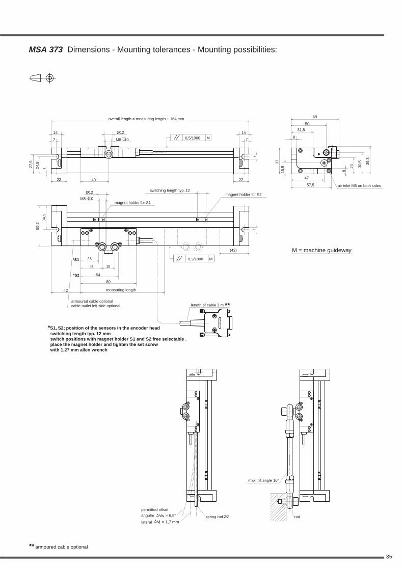
*S1, S2; position of the sensors in the encoder headswitching length typ. 12 mm
with magnet holder S1 and S2 free selectable .place the magnet holder and tighten the set screwwith 1,27 mm allen wrench
switch positions
length of cable 3 m
M = machine guideway
MSA 373 Dimensions - Mounting tolerances - Mounting possibilities:
max. tilt angle 10°
Ø2spring rod rodangular Vw = 6,5°
lateral Vl = 1,7 mm
permitted offset
**
** armoured cable optional
36
• Sinusoidal voltage signals 1 Vpp
MSA 690.03 ±3, ±5, ±10 µm/m 20 µm 1 m/s 2 m/s
MSA 690.01 ±2, ±3 µm/m 10 µm 1 m/s 1 m/s
• Sinusoidal micro-current signals
MSA 690.13 ±3, ±5, ±10 µm/m 20 µm 1 m/s 2 m/s
MSA 690.11 ±2, ±3 µm/m 10 µm 1 m/s 1 m/s
• Square wave Line Driver signals with integrated Subdividing
MSA 690.24 10 µm ±10 µm/m 40 µm
MSA 690.23 5 µm ±5, ±10 µm/m 20 µm
MSA 690.64 2 µm ±5 µm/m 40 µm
MSA 690.63 1 µm ±3, ±5 µm/m 20 µm
MSA 690.73 0,5 µm ±3, ±5 µm/m 20 µm
MSA 690.71 0,25 µm ±2, ±3, ±5 µm/m 10 µm
MSA 690.51 0,1 µm ±2, ±3, ±5 µm/m 10 µm
Signal-outputs (optional):
• sinusoidal voltage signalsMSA 690.03MSA 690.01
Power supply:+5V ±5%, max. 120 mA (unloaded)
Output signals:Encoder signals: 0,6 to 1,2 Vpp, typical 1 Vppwith terminating resistor Zo = 120 ΩReference pulse:0,2 to 0,85 Vss, typical 0,4 V(useable component)with terminating resistor Zo = 120 Ω
Max. output frequency:100 kHz (with 3 m cable)
• sinusoidal micro-current signalsMSA 690.13MSA 690.11
Power supply:+5 V ±5%, max. 120 mA
Output signals:Encoder signals: 7 to 16 µApp,typical 11,5 µApp at 1 KΩ
Reference pulse: 2 to 8 µA,typical 5 µA (useable component) at 1 KΩ
Max. output frequency:100 kHz (with 3 m cable)
• square wave signals (single ended)with integrated Subdividing Electronics
• square wave signals (differential) via Line Driver RS 422 standard
with integrated Subdividing ElectronicsMSA 690.23 = times 1MSA 690.24 = times 1MSA 690.63 = times 5MSA 690.64 = times 5MSA 690.73 = times 10MSA 690.74 = times 10MSA 690.51 = times 25
Power supply:+5 V ±5%, max. 150 mA (unloaded)
MSA 690 Technical data
continuous momentary
0,5 m/s 0,5 m/s(> 300 ns)(> 300 ns)
1 m/s 2 m/s(> 6,6 µs) (> 3,3 µs)
1 m/s 2 m/s(> 3,3 µs) (> 1,6 µs)
1 m/s 1 m/s(> 600 ns)(> 600 ns)
1 m/s 1 m/s(> 300 ns)(> 300 ns)
1 m/s 2 m/s(> 1,2 µs)(> 600 ns)
0,45 m/s 0,45 m/s(> 200 ns)(> 200 ns)
Standard measuring lengths: (mm)70, 120, 170, 220, 270, 320, 370, 420, 470, 520, 620, 720, 820, 920, 1040,1140, 1240, 1340, 1440, 1540, 1640, 1740, 1840, 2040, 2240
Measuring type: glass scale
Free positionable switching magnets for special functions:The position of the 2 switch points (S1 and S2) within the measuring lengthcan be select by the customer (details on page 44 and 45)
Reference mark (RI): selectableMSA 690.xx K:Distance coded Reference marks (K): after travelling 20 mm the absoluteposition will shown on the display.
MSA 690.xx:Up to measuring length 920 mm one Reference mark in the middle of themeasuring length or 35 mm from both ends of measuring length, measuringlength 1040 mm and longer, 45 mm from both ends of measuring length.
Option:One Reference mark at any location, or two or more RI'sseparated by distances of n x 50 mm
Required moving force:with standard sealing lips < 3 N, with low drag sealing lips < 0,2 N
Environmental sealing DIN 40050:IP 53 (with standard sealing lips)IP 64 with DA300 (DA300 see page 57)
Permissible vibration: 100 m/s2 (40 to 2000 Hz)Permissible shock: 200 m/s2 (8 ms)
Permissible temperature: -20°C to +70°C (storage), 0°C to +50°C (operation)
Weight (approx.) 0,8 kg/m (scale spar) + 75 g (scanning head without cable)
* Other accuracy grades or grating pitches (e.g. Inch) upon request
System Accuracy Grating Max. velocityScale model resolution grades pitch (Edge distance)
* *
depending onexternal Subdividing
depending onexternal Subdividing
depending onexternal Subdividing
depending onexternal Subdividing
37
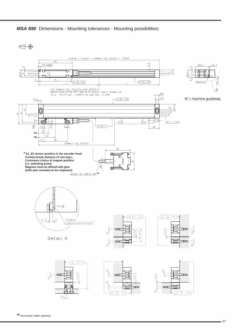
MSA 690 Dimensions - Mounting tolerances - Mounting possibilities:
** armoured cable optional
* S1, S2 sensor position in the encoder headContact-break distance 12 mm (typ.)Customers choice of magnet position(i.e. switching point)Magnets must be affixed with glue(UHU plus included at the shipment)
*S1
*S2
M = machine guideway
**
38
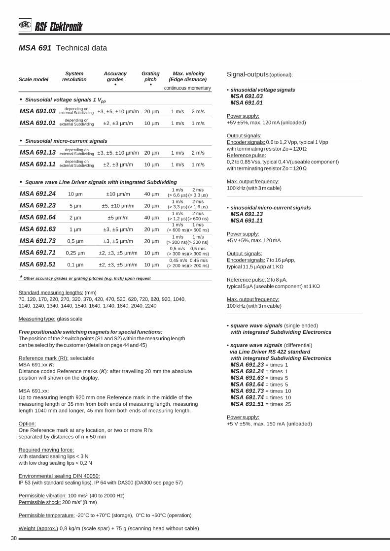
• Sinusoidal voltage signals 1 Vpp
MSA 691.03 ±3, ±5, ±10 µm/m 20 µm 1 m/s 2 m/s
MSA 691.01 ±2, ±3 µm/m 10 µm 1 m/s 1 m/s
• Sinusoidal micro-current signals
MSA 691.13 ±3, ±5, ±10 µm/m 20 µm 1 m/s 2 m/s
MSA 691.11 ±2, ±3 µm/m 10 µm 1 m/s 1 m/s
• Square wave Line Driver signals with integrated Subdividing
MSA 691.24 10 µm ±10 µm/m 40 µm
MSA 691.23 5 µm ±5, ±10 µm/m 20 µm
MSA 691.64 2 µm ±5 µm/m 40 µm
MSA 691.63 1 µm ±3, ±5 µm/m 20 µm
MSA 691.73 0,5 µm ±3, ±5 µm/m 20 µm
MSA 691.71 0,25 µm ±2, ±3, ±5 µm/m 10 µm
MSA 691.51 0,1 µm ±2, ±3, ±5 µm/m 10 µm
Signal-outputs (optional):
• sinusoidal voltage signalsMSA 691.03MSA 691.01
Power supply:+5V ±5%, max. 120 mA (unloaded)
Output signals:Encoder signals: 0,6 to 1,2 Vpp, typical 1 Vppwith terminating resistor Zo = 120 ΩReference pulse:0,2 to 0,85 Vss, typical 0,4 V(useable component)with terminating resistor Zo = 120 Ω
Max. output frequency:100 kHz (with 3 m cable)
• sinusoidal micro-current signalsMSA 691.13MSA 691.11
Power supply:+5 V ±5%, max. 120 mA
Output signals:Encoder signals: 7 to 16 µApp,typical 11,5 µApp at 1 KΩ
Reference pulse: 2 to 8 µA,typical 5 µA (useable component) at 1 KΩ
Max. output frequency:100 kHz (with 3 m cable)
• square wave signals (single ended)with integrated Subdividing Electronics
• square wave signals (differential) via Line Driver RS 422 standard
with integrated Subdividing ElectronicsMSA 691.23 = times 1MSA 691.24 = times 1MSA 691.63 = times 5MSA 691.64 = times 5MSA 691.73 = times 10MSA 691.74 = times 10MSA 691.51 = times 25
Power supply:+5 V ±5%, max. 150 mA (unloaded)
MSA 691 Technical data
0,5 m/s 0,5 m/s(> 300 ns)(> 300 ns)
1 m/s 2 m/s(> 6,6 µs) (> 3,3 µs)
1 m/s 2 m/s(> 3,3 µs) (> 1,6 µs)
1 m/s 1 m/s(> 600 ns)(> 600 ns)
1 m/s 1 m/s(> 300 ns)(> 300 ns)
1 m/s 2 m/s(> 1,2 µs)(> 600 ns)
0,45 m/s 0,45 m/s(> 200 ns)(> 200 ns)
Standard measuring lengths: (mm)70, 120, 170, 220, 270, 320, 370, 420, 470, 520, 620, 720, 820, 920, 1040,1140, 1240, 1340, 1440, 1540, 1640, 1740, 1840, 2040, 2240
Measuring type: glass scale
Free positionable switching magnets for special functions:The position of the 2 switch points (S1 and S2) within the measuring lengthcan be select by the customer (details on page 44 and 45)
Reference mark (RI): selectableMSA 691.xx K:Distance coded Reference marks (K): after travelling 20 mm the absoluteposition will shown on the display.
MSA 691.xx:Up to measuring length 920 mm one Reference mark in the middle of themeasuring length or 35 mm from both ends of measuring length, measuringlength 1040 mm and longer, 45 mm from both ends of measuring length.
Option:One Reference mark at any location, or two or more RI'sseparated by distances of n x 50 mm
Required moving force:with standard sealing lips < 3 Nwith low drag sealing lips < 0,2 N
Environmental sealing DIN 40050:IP 53 (with standard sealing lips), IP 64 with DA300 (DA300 see page 57)
Permissible vibration: 100 m/s2 (40 to 2000 Hz)Permissible shock: 200 m/s2 (8 ms)
Permissible temperature: -20°C to +70°C (storage), 0°C to +50°C (operation)
Weight (approx.) 0,8 kg/m (scale spar) + 75 g (scanning head without cable)
* Other accuracy grades or grating pitches (e.g. Inch) upon request
System Accuracy Grating Max. velocityScale model resolution grades pitch (Edge distance)
* *
depending onexternal Subdividing
depending onexternal Subdividing
depending onexternal Subdividing
depending onexternal Subdividing
continuous momentary

39
M4
M4
1±
0,3
44,6
±0,
3
1±
0,3
1±
0,3
1±
0,3
M4
M4
M4
M4
M4
0,15 0,15 0,15
0,1
M4
** armoured cable optional
MSA 691 Dimensions - Mounting tolerances - Mounting possibilities:
overall length = measuring length + 100 mm
measuring length
air inlet
magnet
A
Detail: A
S
* S1, S2 sensor position in the encoder headContact-break distance 12 mm (typ.)Customers choice of magnet position (i.e. switching point)Magnets must be affixed with glue(UHU plus included at the shipment)
south-pole(is marked)
S
length of cable 3 m
200 ±0,15 continued graduated
M4/4 deep
M
80
74 0,1
0,1
0,1
0,1
40 1 ±0,3Ø8
Ø4,53
20
*S212
44
24
56
59
40
*S1
20
20
0,2 2
12
18±
0,1
54 50
30
SW
8
Ø5,
7
40
4,5
5,4
3 5 4,5
8,9 17
,8 0,2
0±
0,3
M
M
remainder depends of length < 200
M = machine guideway
**
40
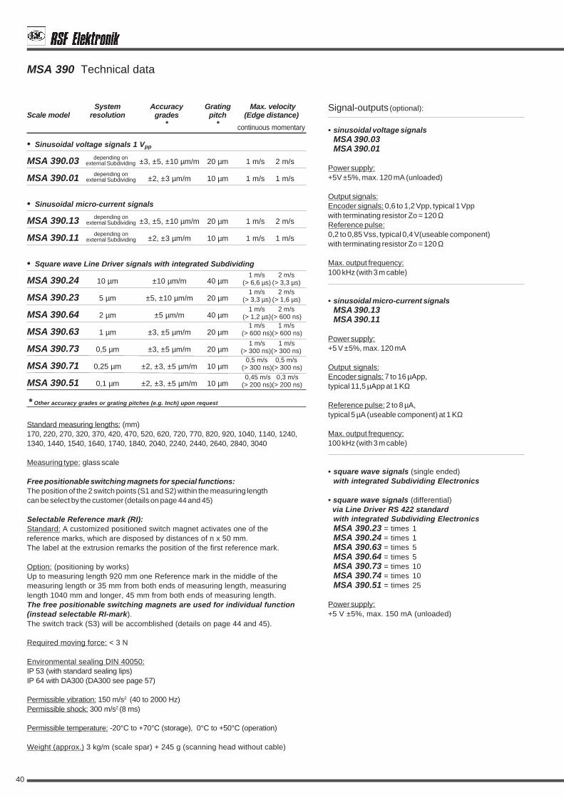
• Sinusoidal voltage signals 1 Vpp
MSA 390.03 ±3, ±5, ±10 µm/m 20 µm 1 m/s 2 m/s
MSA 390.01 ±2, ±3 µm/m 10 µm 1 m/s 1 m/s
• Sinusoidal micro-current signals
MSA 390.13 ±3, ±5, ±10 µm/m 20 µm 1 m/s 2 m/s
MSA 390.11 ±2, ±3 µm/m 10 µm 1 m/s 1 m/s
• Square wave Line Driver signals with integrated Subdividing
MSA 390.24 10 µm ±10 µm/m 40 µm
MSA 390.23 5 µm ±5, ±10 µm/m 20 µm
MSA 390.64 2 µm ±5 µm/m 40 µm
MSA 390.63 1 µm ±3, ±5 µm/m 20 µm
MSA 390.73 0,5 µm ±3, ±5 µm/m 20 µm
MSA 390.71 0,25 µm ±2, ±3, ±5 µm/m 10 µm
MSA 390.51 0,1 µm ±2, ±3, ±5 µm/m 10 µm
Signal-outputs (optional):
• sinusoidal voltage signalsMSA 390.03MSA 390.01
Power supply:+5V ±5%, max. 120 mA (unloaded)
Output signals:Encoder signals: 0,6 to 1,2 Vpp, typical 1 Vppwith terminating resistor Zo = 120 ΩReference pulse:0,2 to 0,85 Vss, typical 0,4 V(useable component)with terminating resistor Zo = 120 Ω
Max. output frequency:100 kHz (with 3 m cable)
• sinusoidal micro-current signalsMSA 390.13MSA 390.11
Power supply:+5 V ±5%, max. 120 mA
Output signals:Encoder signals: 7 to 16 µApp,typical 11,5 µApp at 1 KΩ
Reference pulse: 2 to 8 µA,typical 5 µA (useable component) at 1 KΩ
Max. output frequency:100 kHz (with 3 m cable)
• square wave signals (single ended)with integrated Subdividing Electronics
• square wave signals (differential) via Line Driver RS 422 standard
with integrated Subdividing ElectronicsMSA 390.23 = times 1MSA 390.24 = times 1MSA 390.63 = times 5MSA 390.64 = times 5MSA 390.73 = times 10MSA 390.74 = times 10MSA 390.51 = times 25
Power supply:+5 V ±5%, max. 150 mA (unloaded)
MSA 390 Technical data
0,5 m/s 0,5 m/s(> 300 ns)(> 300 ns)
1 m/s 2 m/s(> 6,6 µs) (> 3,3 µs)
1 m/s 2 m/s(> 3,3 µs) (> 1,6 µs)
1 m/s 1 m/s(> 600 ns)(> 600 ns)
1 m/s 1 m/s(> 300 ns)(> 300 ns)
1 m/s 2 m/s(> 1,2 µs)(> 600 ns)
0,45 m/s 0,3 m/s(> 200 ns)(> 200 ns)
Standard measuring lengths: (mm)170, 220, 270, 320, 370, 420, 470, 520, 620, 720, 770, 820, 920, 1040, 1140, 1240,1340, 1440, 1540, 1640, 1740, 1840, 2040, 2240, 2440, 2640, 2840, 3040
Measuring type: glass scale
Free positionable switching magnets for special functions:The position of the 2 switch points (S1 and S2) within the measuring lengthcan be select by the customer (details on page 44 and 45)
Selectable Reference mark (RI):Standard: A customized positioned switch magnet activates one of thereference marks, which are disposed by distances of n x 50 mm.The label at the extrusion remarks the position of the first reference mark.
Option: (positioning by works)Up to measuring length 920 mm one Reference mark in the middle of themeasuring length or 35 mm from both ends of measuring length, measuringlength 1040 mm and longer, 45 mm from both ends of measuring length.The free positionable switching magnets are used for individual function(instead selectable RI-mark).The switch track (S3) will be accomblished (details on page 44 and 45).
Required moving force: < 3 N
Environmental sealing DIN 40050:IP 53 (with standard sealing lips)IP 64 with DA300 (DA300 see page 57)
Permissible vibration: 150 m/s2 (40 to 2000 Hz)Permissible shock: 300 m/s2 (8 ms)
Permissible temperature: -20°C to +70°C (storage), 0°C to +50°C (operation)
Weight (approx.) 3 kg/m (scale spar) + 245 g (scanning head without cable)
* Other accuracy grades or grating pitches (e.g. Inch) upon request
System Accuracy Grating Max. velocityScale model resolution grades pitch (Edge distance)
* *
depending onexternal Subdividing
depending onexternal Subdividing
depending onexternal Subdividing
depending onexternal Subdividing
continuous momentary
41
** armoured cable optional
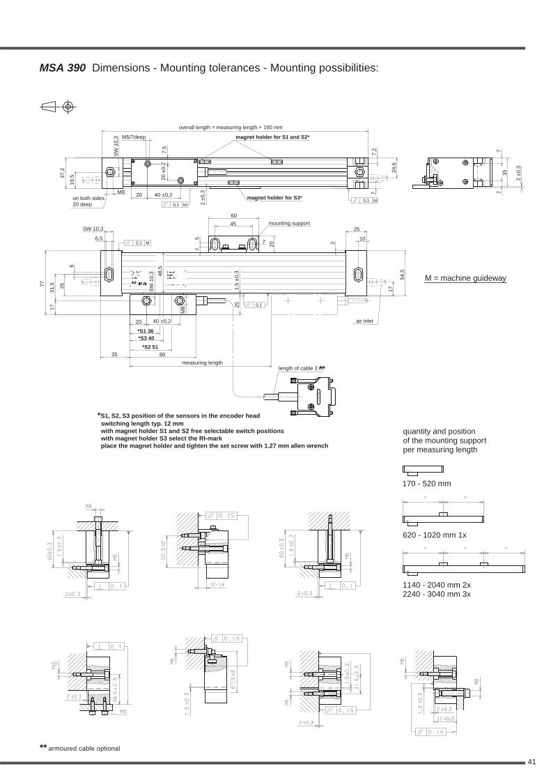
MSA 390 Dimensions - Mounting tolerances - Mounting possibilities:
quantity and positionof the mounting supportper measuring length
170 - 520 mm
620 - 1020 mm 1x
1140 - 2040 mm 2x2240 - 3040 mm 3x
magnet holder for S1 and S2*
magnet holder for S3*
overall length = measuring length + 150 mm
on both sides20 deep
mounting support
length of cable 3 m
air inlet
measuring length
M = machine guideway
*S3 40*S1 36
*S2 51
20
40 ±0,2
45
35
25
10
0,1
0,10,1
0,1
MM
M 7
80
SW 10,3
60
6,5
40 ±0,2
M5/7deep
SW
10,3
SW
10,3
2±
0,3
2±
0,3
24,6
35
2
7,2
7
75
77
48,5
77
17 25
M8
54,5
17
26
6
20
20
7,5
20±
0,2
31,5
1,5
±0,
3
*S1, S2, S3 position of the sensors in the encoder headswitching length typ. 12 mmwith magnet holder S1 and S2 free selectable switch positionswith magnet holder S3 select the RI-markplace the magnet holder and tighten the set screw with 1.27 mm allen wrench
M8
37,2
19,5
**

42
• Sinusoidal voltage signals 1 Vpp
MSA 391.03 ±3, ±5, ±10 µm/m 20 µm 1 m/s 2 m/s
MSA 391.01 ±2, ±3 µm/m 10 µm 1 m/s 1 m/s
• Sinusoidal micro-current signals
MSA 391.13 ±3, ±5, ±10 µm/m 20 µm 1 m/s 2 m/s
MSA 391.11 ±2, ±3 µm/m 10 µm 1 m/s 1 m/s
• Square wave Line Driver signals with integrated Subdividing
MSA 391.24 10 µm ±10 µm/m 40 µm
MSA 391.23 5 µm ±5, ±10 µm/m 20 µm
MSA 391.64 2 µm ±5 µm/m 40 µm
MSA 391.63 1 µm ±3, ±5 µm/m 20 µm
MSA 391.73 0,5 µm ±3, ±5 µm/m 20 µm
MSA 391.71 0,25 µm ±2, ±3, ±5 µm/m 10 µm
MSA 391.51 0,1 µm ±2, ±3, ±5 µm/m 10 µm
Signal-outputs (optional):
• sinusoidal voltage signalsMSA 391.03MSA 391.01
Power supply:+5V ±5%, max. 120 mA (unloaded)
Output signals:Encoder signals: 0,6 to 1,2 Vpp, typical 1 Vppwith terminating resistor Zo = 120 ΩReference pulse:0,2 to 0,85 Vss, typical 0,4 V(useable component)with terminating resistor Zo = 120 Ω
Max. output frequency:100 kHz (with 3 m cable)
• sinusoidal micro-current signalsMSA 391.13MSA 391.11
Power supply:+5 V ±5%, max. 120 mA
Output signals:Encoder signals: 7 to 16 µApp,typical 11,5 µApp at 1 KΩ
Reference pulse: 2 to 8 µA,typical 5 µA (useable component) at 1 KΩ
Max. output frequency:100 kHz (with 3 m cable)
• square wave signals (single ended)with integrated Subdividing Electronics
• square wave signals (differential) via Line Driver RS 422 standard
with integrated Subdividing ElectronicsMSA 391.23 = times 1MSA 391.24 = times 1MSA 391.63 = times 5MSA 391.64 = times 5MSA 391.73 = times 10MSA 391.74 = times 10MSA 391.51 = times 25
Power supply:+5 V ±5%, max. 150 mA (unloaded)
MSA 391 Technical data
0,5 m/s 0,5 m/s(> 300 ns)(> 300 ns)
1 m/s 2 m/s(> 6,6 µs) (> 3,3 µs)
1 m/s 2 m/s(> 3,3 µs) (> 1,6 µs)
1 m/s 1 m/s(> 600 ns)(> 600 ns)
1 m/s 1 m/s(> 300 ns)(> 300 ns)
1 m/s 2 m/s(> 1,2 µs)(> 600 ns)
0,45 m/s 0,3 m/s(> 200 ns)(> 200 ns)
Standard measuring lengths: (mm)170, 220, 270, 320, 370, 420, 470, 520, 620, 720, 770, 820, 920, 1040, 1140, 1240,1340, 1440, 1540, 1640, 1740, 1840, 2040, 2240, 2440, 2640, 2840, 3040
Measuring type: glass scale
Switching magnets for special functions:The position of the 2 switch points (S1 and S2) within the measuring lengthcan be select by the customer (details on page 44 and 45)
Selectable Reference mark (RI):Standard: A customized positioned switch magnet activates one of thereference marks, which are disposed by distances of n x 50 mm.The label at the extrusion remarks the position of the first reference mark.
Option: (positioning by works)Up to measuring length 920 mm one Reference mark in the middle of themeasuring length or 35 mm from both ends of measuring length, measuringlength 1040 mm and longer, 45 mm from both ends of measuring length.The free positionable switching magnets are used for individual function(instead selectable RI-mark).The switch track (S3) will be accomblished (details on page 44 and 45).
Required moving force: < 3 N
Environmental sealing DIN 40050:IP 53 (with standard sealing lips)IP 64 with DA300 (DA300 see page 57)
Permissible vibration: 150 m/s2 (40 to 2000 Hz)Permissible shock: 300 m/s2 (8 ms)
Permissible temperature: -20°C to +70°C (storage), 0°C to +50°C (operation)
Weight (approx.) 3 kg/m (scale spar) + 245 g (scanning head without cable)
* Other accuracy grades or grating pitches (e.g. Inch) upon request
System Accuracy Grating Max. velocityScale model resolution grades pitch (Edge distance)
* *
depending onexternal Subdividing
depending onexternal Subdividing
depending onexternal Subdividing
depending onexternal Subdividing
continuous momentary

43
** armoured cable optional
MSA 391 Dimensions - Mounting tolerances - Mounting possibilities:
*S1, S2, S3 position of the sensors in the encoder headswitching length typ. 12 mmwith magnet holder S1 and S2 free selectable switch positionswith magnet holder S3 select the RI-markplace the magnet holder and tighten the set screw with 1.27 mm allen wrench
magnet holder for S1 and S2*
magnet holder for S3*
overall length = measuring length + 110 mm
length of cable 3 m
air inlet
measuring length
M = machine guideway
*S3 40*S3 40*S1 36*S1 36
*S2 51*S2 51
remainder depends on length200 ±0,15 continued graduated
**

44
Positioning of the switching magnets
magnet holder
S3
magnet
S1S2
S1
Switch points S1 and S2 for individual functionMSA 690 MSA 691
HALL sensorsS1
(S1) 24
(S2) 40
S2
24 65
magnetic switch magnetic switch
permissible tolerance for magnetic switch
HALL sensors
S1S2
24 60
(S1) 24
(S2) 40
magnetic switch magnetic switch
permissible tolerance for magnetic switch
MSA 373
42
68 68
(S1) 26
(S2) 54
magnetic switchfor S1
magnetic switchfor S2
permissible tolerance for magnetic switch
Selectable Reference mark (RI)MSA 390 MSA 391
Version without RI-variety: Switch point S3 for additionally individual functionMSA 390 MSA 391
magnetic switch
50 continued graduated
10
beginning of the measuring length
35 (S3) 40
S3
501. RI 2. RI85
First Reference MarkFirst Reference MarkRI
HALL sensor
35
S3
75 75
(S3) 40
magnetic switch
permissible tolerance for magnetic switch
50 continued graduated
beginning of the measuring length
15 (S3) 40
S3
501. RI 2. RI65
10
First Reference MarkFirst Reference MarkRI
HALL sensor
magnetic switch
15
S3
55 55
(S3) 40
magnetic switch
permissible tolerance for magnetic switch
35
HALL sensors
S1 S2
71 64
(S2) 51
(S1) 36
magnetic switch
permissible tolerance for magnetic switch
15
HALL sensors
S1 S2
51 44
(S2) 51
(S1) 36
magnetic switch
permissible tolerance for magnetic switch
MSA 390 MSA 391

45
MSA 690, MSA 691, MSA 390, MSA 391, MSA 373 pin-outs
SUB MIN-D connectorSUB MIN-D connectorSUB MIN-D connectorSUB MIN-D connectorSUB MIN-D connector 15-pin
* exception at MSA 390 and MSA 391 (Version without RI-variety): PIN 1 = S3 (switch output)** PIN 2 = GND (bridge to PIN 9) or sensor*** PIN 7 = +5V (bridge to PIN 8) or sensorouter shield on chassis
PIN 1* 2** 3 4 5 6 7*** 8 9 10 11 12 13 14 15
square wave signals nc GND nc RI T2 T1 +5V +5V GND S1 S2 RI T2 T1 shieldvia Line Driver
sinusiodal nc GND nc RI- 90°- 0°- +5V +5V GND S1 S2 RI+ 90°+ 0°+ shieldmicro-current signals
sinusoidal voltage nc GND nc RI A2 A1 +5V +5V GND S1 S2 RI A2 A1 shieldsignals
59
40
16
MSA 690, MSA 691, MSA 390, MSA 391, MSA 373 switch signalsVersion 1TTL output (active high)
SUB MIN-D connector 15-pin
S1, S2, S3 = TTL output
I = 20 mA (low level < 0,8 V)I = 1 mA (high level > 2 V)
Magnet
high
low
OutputsignalsS1, S2, S3
HAL-sensor
scanning head
+5V
S2
0V
S1
S3
BCW60
BCW60
BCW60
2K2
2K2
2K2
2K2
2K2
2K2
HAL506
HAL506
HAL506
S1
S3
S2
SOURCE
SINK
15
9
8
6
1
scanning head
S1, S2, S3 = open collector outputI = 20 mA (low level < 0,8 V)SINK
Version 2open collector output (active high impedance)
SUB MIN-D connector 15-pin
Magnet
high
low
OutputsignalsS1, S2, S3
HAL-sensor
+5V
S2
0V
S1
S3
BCW60
BCW60
BCW60
2K2
2K2
2K2
HAL506
HAL506
HAL506
S1
S3
S2 15
9
8
6
1
0 V bis +24 V
S3
S1
S2
S1, S2, S3 = TTL output
I = 20 mA (low level < 0,8 V)I = 1 mA (high level > 2 V)
Magnet
high
lowOutputsignalsS1, S2, S3
HAL-sensor
SOURCE
SINK
Version 3TTL output (active low)
+5V
S2
0V
S1
2K2
2K2
HAL506
HAL506
S1
S2
S3
SUB MIN-D connector 15-pin
15
9
8
6
1
S3
2K2
HAL506
scanning head Magnet
high
lowOutputsignalsS1, S2, S3
HAL-sensor
S1, S2, S3 = open collector outputI = 20 mA (low level < 0,8 V)
Version 4open collector output (active low)
SINK
+5V
S2
0V
S1
HAL506
HAL506
S1
S2
S3
SUB MIN-D connector 15-pin
15
9
8
6
1
S3HAL506
0 V bis +24 V
S3
S1
S2
scanning head

46
• Sinusoidal micro-current signals
MSA 650.13 ±5, ±10 µm/m 20 µm 1 m/s 2 m/s
• Square wave Line Driver signals with integrated Subdividing
MSA 650.24 10 µm ±10 µm/m 40 µm
MSA 650.23 5 µm ±5, ±10 µm/m 20 µm
MSA 650.33 2,5 µm ±5, ±10 µm/m 20 µm
MSA 650.64 2 µm ±5, ±10 µm/m 40 µm
MSA 650.63 1 µm ±5, ±10 µm/m 20 µm
MSA 650.73 0,5 µm ±5, ±10 µm/m 20 µm
Signal-outputs (optional):
• sinusoidal micro-current signalsMSA 650.13
Power supply:+5 V ±5%, max. 90 mA
Output signals:Encoder signals: 7 to 16 µApp,typical 11,5 µApp at 1 KΩ
Reference pulse: 2 to 8 µA,typical 5 µA (useable component) at 1 KΩ
Max. output frequency:100 kHz (with 3 m cable)
• square wave signals (single ended)with integrated Subdividing Electronics
• square wave signals (differential) via Line Driver RS 422 standard
with integrated Subdividing ElectronicsMSA 650.23 = times 1MSA 650.24 = times 1MSA 650.33 = times 2MSA 650.63 = times 5MSA 650.64 = times 5MSA 650.73 = times 10
Power supply:+5 V ±5%, < 150 mA (with interpolation, unloaded)
< 200 mA (without interpolation, unloaded)
MSA 650 Technical data
1 m/s 2 m/s(> 5 µs) (> 2,5 µs)
1 m/s 2 m/s(> 2,5 µs) (> 1,2 µs)
1 m/s 2 m/s(> 800 ns)(> 400 ns)
1 m/s 1 m/s(> 400 ns)(> 400 ns)
1 m/s 1 m/s(> 1,2 µs) (> 1,2 µs)
1 m/s 1 m/s(> 200 ns)(> 200 ns)
Standard measuring lengths: (mm)170, 220, 270, 320, 370, 420, 470, 520, 620, 720, 770, 820, 920, 1040, 1140,1240, 1340, 1440, 1540, 1640, 1740
Measuring type: glass scale
Reference mark (RI): selectableMSA 650.xx K:Distance coded Reference marks (K): after travelling 20 mm the absoluteposition will shown on the display.
MSA 650.xx:Up to measuring length 920 mm one Reference mark in the middle of themeasuring length or 35 mm from both ends of measuring length, measuringlength 1040 mm and longer, 45 mm from both ends of measuring length.
Option:One Reference mark at any location, or two or more RI's separated bydistances of n x 50 mm
Required moving force:with standard sealing lips < 3 Nwith low drag sealing lips < 0,2 N
Environmental sealing DIN 40050:IP 53 (with standard sealing lips)
Permissible vibration: 80 m/s2 (40 to 2000 Hz)Permissible shock: 200 m/s2 (8 ms)
Permissible temperature:-20°C to +70°C (storage), 0°C to +50°C (operation)
Weight (approx.)0,8 kg/m (scale spar) + 85 g (scanning head without cable)
* Other accuracy grades or grating pitches (e.g. Inch) upon request
System Accuracy Grating Max. velocityScale model resolution grades pitch (Edge distance)
* *
depending onexternal Subdividing
continuous momentary
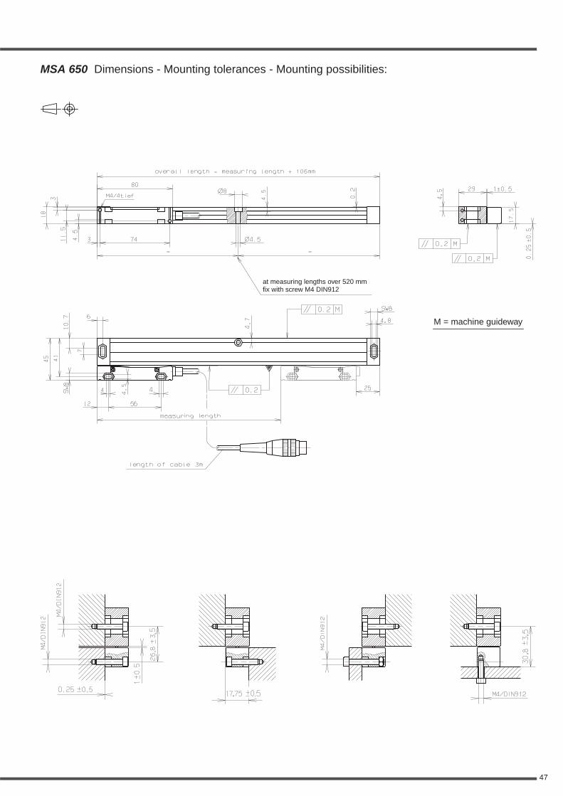
47
M = machine guideway
at measuring lengths over 520 mmfix with screw M4 DIN912
MSA 650 Dimensions - Mounting tolerances - Mounting possibilities:

48
• Sinusoidal micro-current signals
MSA 651.13 ±5, ±10 µm/m 20 µm 1 m/s 2 m/s
• Square wave Line Driver signals with integrated Subdividing
MSA 651.24 10 µm ±10 µm/m 40 µm
MSA 651.23 5 µm ±5, ±10 µm/m 20 µm
MSA 651.33 2,5 µm ±5, ±10 µm/m 20 µm
MSA 651.64 2 µm ±5, ±10 µm/m 40 µm
MSA 651.63 1 µm ±5, ±10 µm/m 20 µm
MSA 651.73 0,5 µm ±5, ±10 µm/m 20 µm
Signal-outputs (optional):
• sinusoidal micro-current signalsMSA 651.13
Power supply:+5 V ±5%, max. 90 mA
Output signals:Encoder signals: 7 to 16 µApp,typical 11,5 µApp at 1 KΩ
Reference pulse: 2 to 8 µA,typical 5 µA (useable component) at 1 KΩ
Max. output frequency:100 kHz (with 3 m cable)
• square wave signals (single ended)with integrated Subdividing Electronics
• square wave signals (differential) via Line Driver RS 422 standard
with integrated Subdividing ElectronicsMSA 651.23 = times 1MSA 651.24 = times 1MSA 651.33 = times 2MSA 651.63 = times 5MSA 651.64 = times 5MSA 651.73 = times 10
Power supply:+5 V ±5%, < 150 mA (with interpolation, unloaded)
< 200 mA (without interpolation, unloaded)
MSA 651 Technical data
1 m/s 2 m/s(> 5 µs) (> 2,5 µs)
1 m/s 2 m/s(> 2,5 µs) (> 1,2 µs)
1 m/s 2 m/s(> 800 ns)(> 400 ns)
1 m/s 1 m/s(> 400 ns)(> 400 ns)
1 m/s 1 m/s(> 1,2 µs) (> 1,2 µs)
1 m/s 1 m/s(> 200 ns)(> 200 ns)
Standard measuring lengths: (mm)170, 220, 270, 320, 370, 420, 470, 520, 620, 720, 770, 820, 920, 1040, 1140,1240, 1340, 1440, 1540, 1640, 1740, 1840, 2040, 2240
Measuring type: glass scale
Reference mark (RI): selectableMSA 651.xx K:Distance coded Reference marks (K): after travelling 20 mm the absoluteposition will shown on the display.
MSA 651.xx:Up to measuring length 920 mm one Reference mark in the middle of themeasuring length or 35 mm from both ends of measuring length, measuringlength 1040 mm and longer, 45 mm from both ends of measuring length.
Option:One Reference mark at any location, or two or more RI's separated bydistances of n x 50 mm
Required moving force:with standard sealing lips < 3 Nwith low drag sealing lips < 0,2 N
Environmental sealing DIN 40050:IP 53 (with standard sealing lips)
Permissible vibration: 80 m/s2 (40 to 2000 Hz)Permissible shock: 200 m/s2 (8 ms)
Permissible temperature:-20°C to +70°C (storage), 0°C to +50°C (operation)
Weight (approx.)0,8 kg/m (scale spar) + 85 g (scanning head without cable)
* Other accuracy grades or grating pitches (e.g. Inch) upon request
System Accuracy Grating Max. velocityScale model resolution grades pitch (Edge distance)
* *
depending onexternal Subdividing
continuous momentary

49
M = machine guideway
MSA 651 Dimensions - Mounting tolerances - Mounting possibilities:
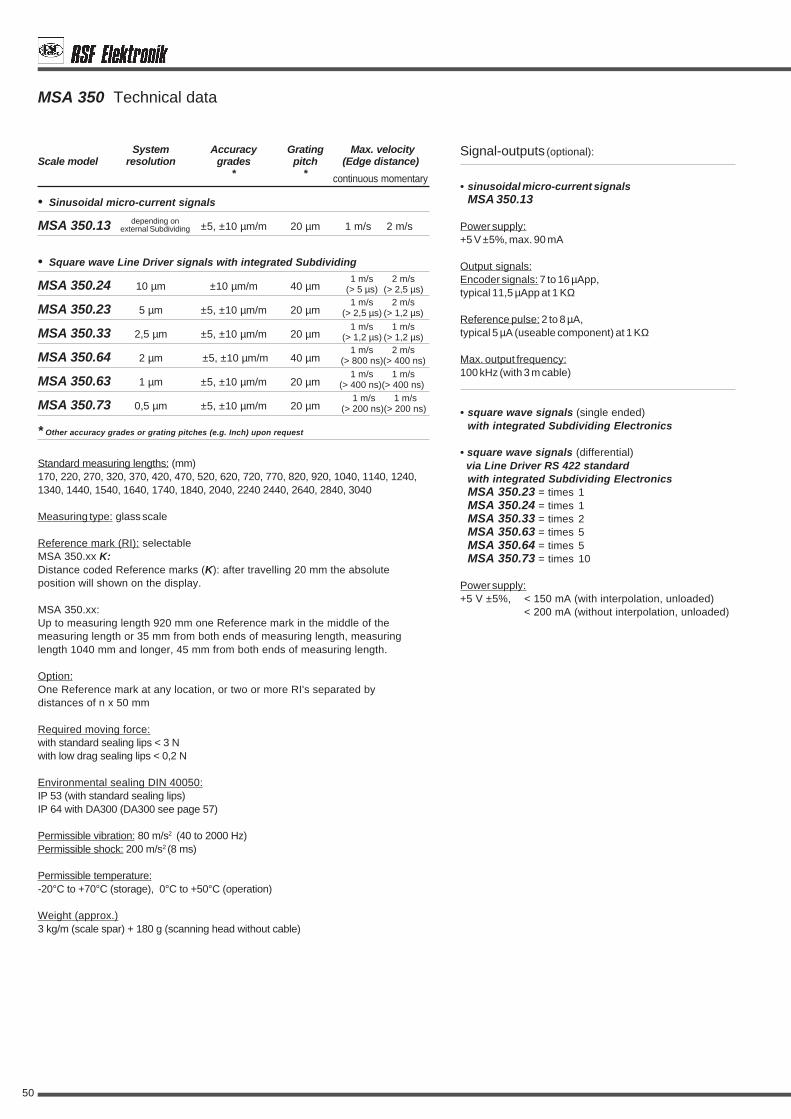
50
• Sinusoidal micro-current signals
MSA 350.13 ±5, ±10 µm/m 20 µm 1 m/s 2 m/s
• Square wave Line Driver signals with integrated Subdividing
MSA 350.24 10 µm ±10 µm/m 40 µm
MSA 350.23 5 µm ±5, ±10 µm/m 20 µm
MSA 350.33 2,5 µm ±5, ±10 µm/m 20 µm
MSA 350.64 2 µm ±5, ±10 µm/m 40 µm
MSA 350.63 1 µm ±5, ±10 µm/m 20 µm
MSA 350.73 0,5 µm ±5, ±10 µm/m 20 µm
Signal-outputs (optional):
• sinusoidal micro-current signalsMSA 350.13
Power supply:+5 V ±5%, max. 90 mA
Output signals:Encoder signals: 7 to 16 µApp,typical 11,5 µApp at 1 KΩ
Reference pulse: 2 to 8 µA,typical 5 µA (useable component) at 1 KΩ
Max. output frequency:100 kHz (with 3 m cable)
• square wave signals (single ended)with integrated Subdividing Electronics
• square wave signals (differential) via Line Driver RS 422 standard
with integrated Subdividing ElectronicsMSA 350.23 = times 1MSA 350.24 = times 1MSA 350.33 = times 2MSA 350.63 = times 5MSA 350.64 = times 5MSA 350.73 = times 10
Power supply:+5 V ±5%, < 150 mA (with interpolation, unloaded)
< 200 mA (without interpolation, unloaded)
1 m/s 2 m/s(> 5 µs) (> 2,5 µs)1 m/s 2 m/s
(> 2,5 µs) (> 1,2 µs)
1 m/s 2 m/s(> 800 ns)(> 400 ns)
1 m/s 1 m/s(> 400 ns)(> 400 ns)
1 m/s 1 m/s(> 1,2 µs) (> 1,2 µs)
1 m/s 1 m/s(> 200 ns)(> 200 ns)
Standard measuring lengths: (mm)170, 220, 270, 320, 370, 420, 470, 520, 620, 720, 770, 820, 920, 1040, 1140, 1240,1340, 1440, 1540, 1640, 1740, 1840, 2040, 2240 2440, 2640, 2840, 3040
Measuring type: glass scale
Reference mark (RI): selectableMSA 350.xx K:Distance coded Reference marks (K): after travelling 20 mm the absoluteposition will shown on the display.
MSA 350.xx:Up to measuring length 920 mm one Reference mark in the middle of themeasuring length or 35 mm from both ends of measuring length, measuringlength 1040 mm and longer, 45 mm from both ends of measuring length.
Option:One Reference mark at any location, or two or more RI's separated bydistances of n x 50 mm
Required moving force:with standard sealing lips < 3 Nwith low drag sealing lips < 0,2 N
Environmental sealing DIN 40050:IP 53 (with standard sealing lips)IP 64 with DA300 (DA300 see page 57)
Permissible vibration: 80 m/s2 (40 to 2000 Hz)Permissible shock: 200 m/s2 (8 ms)
Permissible temperature:-20°C to +70°C (storage), 0°C to +50°C (operation)
Weight (approx.)3 kg/m (scale spar) + 180 g (scanning head without cable)
* Other accuracy grades or grating pitches (e.g. Inch) upon request
System Accuracy Grating Max. velocityScale model resolution grades pitch (Edge distance)
* *
depending onexternal Subdividing
MSA 350 Technical data
continuous momentary

51
M = machine guideway
MSA 350 Dimensions - Mounting tolerances - Mounting possibilities:
quantity and positionof the mounting supportper measuring length
170 - 520 mm
620 - 1020 mm 1x
1140 - 2040 mm 2x2240 - 3040 mm 3x
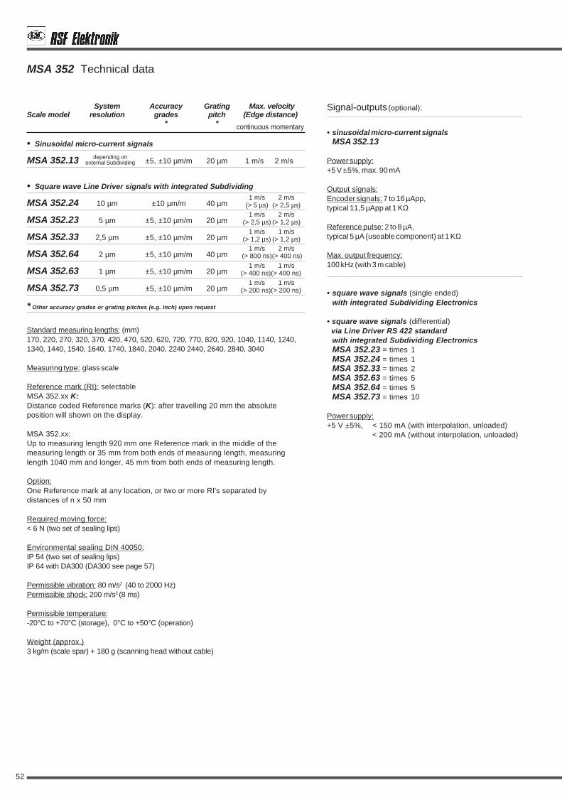
52
System Accuracy Grating Max. velocityScale model resolution grades pitch (Edge distance)
* *
• Sinusoidal micro-current signals
MSA 352.13 ±5, ±10 µm/m 20 µm 1 m/s 2 m/s
• Square wave Line Driver signals with integrated Subdividing
MSA 352.24 10 µm ±10 µm/m 40 µm
MSA 352.23 5 µm ±5, ±10 µm/m 20 µm
MSA 352.33 2,5 µm ±5, ±10 µm/m 20 µm
MSA 352.64 2 µm ±5, ±10 µm/m 40 µm
MSA 352.63 1 µm ±5, ±10 µm/m 20 µm
MSA 352.73 0,5 µm ±5, ±10 µm/m 20 µm
Signal-outputs (optional):
• sinusoidal micro-current signalsMSA 352.13
Power supply:+5 V ±5%, max. 90 mA
Output signals:Encoder signals: 7 to 16 µApp,typical 11,5 µApp at 1 KΩ
Reference pulse: 2 to 8 µA,typical 5 µA (useable component) at 1 KΩ
Max. output frequency:100 kHz (with 3 m cable)
• square wave signals (single ended)with integrated Subdividing Electronics
• square wave signals (differential) via Line Driver RS 422 standard
with integrated Subdividing ElectronicsMSA 352.23 = times 1MSA 352.24 = times 1MSA 352.33 = times 2MSA 352.63 = times 5MSA 352.64 = times 5MSA 352.73 = times 10
Power supply:+5 V ±5%, < 150 mA (with interpolation, unloaded)
< 200 mA (without interpolation, unloaded)
MSA 352 Technical data
continuous momentary
1 m/s 2 m/s(> 5 µs) (> 2,5 µs)1 m/s 2 m/s
(> 2,5 µs) (> 1,2 µs)
1 m/s 2 m/s(> 800 ns)(> 400 ns)
1 m/s 1 m/s(> 400 ns)(> 400 ns)
1 m/s 1 m/s(> 1,2 µs) (> 1,2 µs)
1 m/s 1 m/s(> 200 ns)(> 200 ns)
Standard measuring lengths: (mm)170, 220, 270, 320, 370, 420, 470, 520, 620, 720, 770, 820, 920, 1040, 1140, 1240,1340, 1440, 1540, 1640, 1740, 1840, 2040, 2240 2440, 2640, 2840, 3040
Measuring type: glass scale
Reference mark (RI): selectableMSA 352.xx K:Distance coded Reference marks (K): after travelling 20 mm the absoluteposition will shown on the display.
MSA 352.xx:Up to measuring length 920 mm one Reference mark in the middle of themeasuring length or 35 mm from both ends of measuring length, measuringlength 1040 mm and longer, 45 mm from both ends of measuring length.
Option:One Reference mark at any location, or two or more RI's separated bydistances of n x 50 mm
Required moving force:< 6 N (two set of sealing lips)
Environmental sealing DIN 40050:IP 54 (two set of sealing lips)IP 64 with DA300 (DA300 see page 57)
Permissible vibration: 80 m/s2 (40 to 2000 Hz)Permissible shock: 200 m/s2 (8 ms)
Permissible temperature:-20°C to +70°C (storage), 0°C to +50°C (operation)
Weight (approx.)3 kg/m (scale spar) + 180 g (scanning head without cable)
* Other accuracy grades or grating pitches (e.g. Inch) upon request
depending onexternal Subdividing

53
M = machine guideway
MSA 352 Dimensions - Mounting tolerances - Mounting possibilities:
quantity and positionof the mounting supportper measuring length
170 - 520 mm
620 - 1020 mm 1x
1140 - 2040 mm 2x2240 - 3040 mm 3x

54
Subdividing Electronics ZE
ZE-Sx• for Linear Encoders with sinusoidal voltage
signals
ZE-Vx• for Linear Encoders with sinusoidal
micro-current signals
Interpolation:ZE-S5, ZE-V5 = times 5ZE-S10, ZE-V10 = times 10ZE-S20, ZE-V20 = times 20ZE-S25, ZE-V25 = times 25ZE-S50, ZE-V50 = times 50ZE-S100, ZE-V100 = times 100ZE-S200, ZE-V200 = times 200(in preparation)ZE-S400, ZE-V400 = times 400(in preparation)
Power supply: +5 V ±5%
Current consumption: 150 mA- Linear Encoder not connected- output signals loaded
Connectors:(pin-outs and dimensions on page 56)Input: chassis connector female9-pin FB 91 (ZE-V) or 12-pin FB 121 (ZE-S)Output: chassis connector male12-pin FS 121 or 1 m cable with maleconnector 12-pin L121
Input signals ZE-Sx:Encoder signals: sinusoidal voltage signals0,6 to 1,2 Vpp (1Vss typical)Reference pulse: 0,2 to 0,85 V0,2 to 0,85 Vpptypical 0,4 V (useable component)with terminating impedance Zo = 120 Ω
Input signals ZE-Vx:Encoder signals: sinusoidal micro-currentsignals 7 to 16 µA Ipp (11,5 µA typical)Reference pulse: 2 to 8 µA Ipp (5 µA typical)
Max. input frequency:ZE-S5, ZE-V5 = 100 kHz, tF > 300 nsZE-S10, ZE-V10 = 50 kHz, tF > 300 nsZE-S20, ZE-V20 = 56 kHz, tF > 200 nsZE-S25, ZE-V25 = 45 kHz, tF > 200 nsZE-S50, ZE-V50 = 45 kHz, tF > 100 nsZE-S100, ZE-V100 = 22,5 kHz, tF > 100 ns
Output signals:Square wave signals + Reference pulsevia Line Driver RS 422 standard or singleended phaseshift 90° el.
Dimensions::
ZE-xx Subdividing Electronic is available forapplications where the Linear Encoder has asinusoidal micro-current or sinusoidal voltageoutput. It is connected between the LinearEncoder and the Control orDigital Readout.
The ZE-xx divides the scale grating pitch toachieve finer resolutions and outputs squarewave signals.In addition, differential (complementary)Line Driver signals are output.The Subdividing Electronic units are suppliedin rugged housings, meeting the sealingrequirements of IP 64.
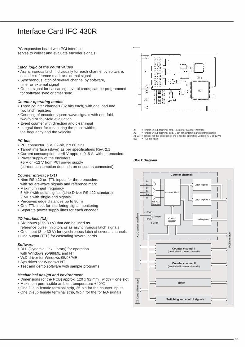
55
Counter channel ICounter channel I
Counter 32-bitCounter 32-bit
Latch register ILatch register I
Latch register IILatch register II
ControlregisterControlregister
Load registerLoad register
RS 422ReceiverRS 422Receiver
A+
A-
B+
B-
R+
R-
+12 V
+5 VJumper
GND
X1
Cou
nter
inte
rfac
eX
1C
ount
erin
terf
ace
PC
Iint
erfa
ceP
CIi
nter
face
X2
Con
trol
inte
rfac
eX
2C
ontr
olin
terf
ace
Counter channel II(identical with counter channel I)
Counter channel II(identical with counter channel I)
Counter channel III(identical with counter channel I)
Counter channel III(identical with counter channel I)
Timer
Switching and control signalsSwitching and control signals
Block Diagram
X1 = female D-sub terminal strip, 25-pin for counter interfaceX2 = female D-sub terminal strip, 9-pin for switching and control signalsJ1-J3 = jumper for the selection of the encoder operating voltage (5 V or 12 V)IC1 = PCI interface
Latch logic of the count values• Asynchronous latch individually for each channel by software,
encoder reference mark or external signal• Synchronous latch of several channel by software,
timer or external signal• Output signal for cascading several cards; can be programmed
for software sync or timer sync.
Counter operating modes• Three counter channels (32 bits each) with one load and
two latch registers• Counting of encoder square-wave signals with one-fold,
two-fold or four-fold evaluation• Event counter with direction and clear input• Integral timer for measuring the pulse widths,
the frequency and the velocity.
PC bus• PCI connector, 5 V, 32-bit, 2 x 60 pins• Target interface (slave) as per specifications Rev. 2.1• Current consumption at +5 V approx. 0.,5 A, without encoders• Power supply of the encoders:
+5 V or +12 V from PCI power supply(current consumption depends on encoders connected)
Counter interface (X1)• Nine RS 422 or. TTL inputs for three encoders
with square-wave signals and reference mark• Maximum input frequency
5 MHz with delta signals (Line Driver RS 422 standard)2 MHz with single-end signals
• Perceives edge distances up to 80 ns• One TTL input for interfering-signal monitoring• Separate power supply lines for each encoder
I/O interface (X2)• Six inputs (3 to 30 V) that can be used as
reference pulse inhibitors or as asynchronous latch signals• One input (3 to 30 V) for synchronous latch of several channels• One output (TTL) for cascading several cards
Software• DLL (Dynamic Link Library) for operation
with Windows 95/98/ME and NT• VxD driver for Windows 95/98/ME• Sys driver for Windows NT• Test and demo software with sample programs
Mechanical design and environment• Dimensions (of the PCB) approx. 120 x 92 mm width = one slot• Maximum permissible ambient temperature +40°C• One D-sub female terminal strip, 25-pin for the counter inputs• One D-sub female terminal strip, 9-pin for the for I/O-signals
Interface Card IFC 430R
PC expansion board with PCI interface,serves to collect and evaluate encoder signals
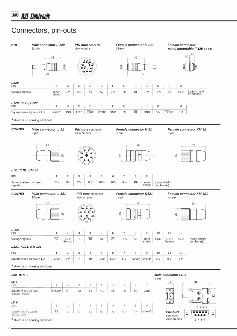
56
LD 9PIN 1 2 3 4 5 6 7 8 9
Square wave signals T1 T1 T2 T2 RI RI +5 V 0 V shield*
Male connector L 12012-pin
Connectors, pin-outs
DINDINDINDINDIN
L120, K120, F120PIN A B C D E F G H J K L M
Square wave signals + LD shield* GND T1/0° T1/0° T2/90° GND RI RI GND 5 V T2/90° 5 V
Female connectorpanel mountable F 120 12-pin
Female connector K 12012-pin
Male connector L 919-pin
Female connector K 919-pin
Female connector KM 919-pin
L 91, K 91, KM 91
PIN 1 2 3 4 5 6 7 8 9
Sinusoidal micro-current 0°+ 0°- 5 V 0 V 90°+ 90°- RI+ RI- inner (outer shieldsignals shield on chassis)
L121, K121, KM 121
PIN 1 2 3 4 5 6 7 8 9 10 11 12
Square wave signals + LD T2/90° 5 V RI RI T1/0° T1/0° 5 V T2/90° shield* 0 V 0 V 5 V
SUB MIN-DSUB MIN-DSUB MIN-DSUB MIN-DSUB MIN-D
LD 9PIN 1 2 3 4 5 6 7 8 9
Square wave signals shield* RI T2 T1 +V nc nc nc GND
Male connector LD 99-pin
* shield is on housing additional
* shield is on housing additional
* shield is on housing additional
L120PIN A B C D E F G H J K L M
Voltage signals inner 0 V A1 A1 A2 0 V RI RI 0 V +5 V A2 +5 Vshield
(outer shieldon chassis)
42
Ø18
70
42
Ø18
70
131,5
Ø20
BA
EFG
MHJ CL
D
K
PIN outs connectorview on pins
CONNEI
52
25
52
25
52
25
9 78
6
54
3
21
9
6
810
11
127
5 4
1
2
3
52
25
52
25
52
25
CONNEI
PIN outs connectorview on pins
L 121PIN 1 2 3 4 5 6 7 8 9 10 11 12
Voltage signals A2 +5 V RI RI A1 A1 +5 V A2 inner GND GND +5 V (outer shieldSensor shield Sensor on chassis)
Male connector L 12112-pin
PIN outs connectorview on pins
Female connector K12112-pin
Female connector KM 12112-pin
5916
32
97 8
54321
6
PIN outsconnectorview on pins
(single ended)
(differential)

57
Air Pressure Unit DA300
* = Space necessary for filter change* = Space necessary for filter change
23,5 100
230
Ø12
3050
7
7
5
76
101
45
80*
80*
1113
313
3
R1/
4’’
R1/
4’’
R 1/8’’R 1/8’’
123
147
31
12
0
12
3
4
6,5
15,5
Ø11
,8 13
Ø3,2
In harsh environments, where oiland coolant are present, additionalprecautions should be taken.To insure fail-safe operation of theLinear Encoder, only "clean" air shouldbe put into the scale housing.The air should be free from oil mist andwater vapor.The air has to be cleaned using a goodfiltration system.
The scale cavity should have amaximum overpressure of 0,3 to 0,6 barat a flow rate of about 4 l/min(per Linear Encoder).DA300 consists of a pressure regulatorwith gauge, prefilter, and an automaticdrain with microfilter.
The required supply overpressure ismin. 4 bar, max. 16 bar.To avoid measuring errors due tothermal differences, it is absolutelynecessary to provide pressurized airthat has the same temperature as themachine tool. This is especially impor-tant with single sets of sealing lips(see also page 8, sealing).
Dimensions:

58
Other RSF-Products
MS 50Reflective scanningLinear Encoder• non-contact reflective scanning• for high displacement velocities• small version• different scale versions• max. measuring length
(depends on scale version)- glass scale to 3040 mm- steel tape scale to 30 m
DG 118, DG 120Standard Rotary Encoder• Rotary Encoder
for unsiversal application• standard line/rev.
graduated from 100 to 5.400
MS 61Reflective scanningLinear Encoder• two switch tracks
for individual special function• non-contact reflective scanning• for high displacement velocities• flat version• different scale versions• max. measuring length
(depends on scale version)- glass scale to 3040 mm- steel tape scale to 30 m
MS 8xInterferential Linear Encoder• two switch tracks
for individual special functions• non-contact reflective scanning• for high displacement velocities• small version• scale version: glass scale
or ROBAX glassceramicwith phase grating
• max. measuring lengthto 2440 mm
MSG 10Linear Encoder withself-guided scanning head• easy mounting• for high displacement velocities• scale version: steel tape scale
on aluminium carrier• max. measuring length 400 mm
TDE 60Two dimensional Encoder• non-contact reflective scanning• small version• scale version: glass scale• measuring range 360 x 360 mm
MSR 50 MSModular Ring Rotary Encoder• steel tape scale on steel ring• for applications at the robotik,
on printer and roundtables• non-contact reflective scanning• available diameter
Ø80 mm to Ø165 mm
MSR 50 MKModular Ring Rotary Encoder• steel tape scale on
sandwich clampingring• for application at the robotik
on printers and roundtables• non-contact reflective scanning• available diameter
Ø150 mm to Ø500 mm
DIT 10, DIT 30, DIT 48Precision measuring Probes• for universal applications• stroke length 10, 30, 48 mm• mounting on shaft sleeve• mounting with two tapped
holes on body (DIT 30, DIT 48)• with cable lifter• integrated pneumatic lifter
optional• sealing bellows optional
(DIT 30, DIT 48)
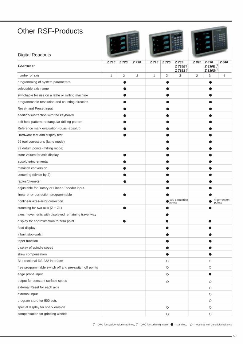
59
Other RSF-Products
!!!!! !!!!!
Features:
number of axis
programming of system parameters
selectable axis name
switchable for use on a lathe or milling machine
programmable resolution and counting direction
Reset- and Preset input
addition/subtraction with the keyboard
bolt hole pattern, rectangular drilling pattern
Reference mark evaluation (quasi-absolut)
Hardware test and display test
99 tool corrections (lathe mode)
99 datum points (milling mode)
store values for axis display
absolute/incremental
mm/inch conversion
centering (divide by 2)
radius/diameter
adjustable for Rotary or Linear Encoder input.
linear error correction programmable
nonlinear axes-error correction
summing for two axis (Z + Z1)
axes movements with displayed remaining travel way
display for approximation to zero point
feed display
inbuilt stop-watch
taper function
display of spindle speed
skew compensation
Bi-directional RS 232 interface
free programmable switch off and pre-switch off points
edge probe input
output for constant surface speed
external Reset for each axis
external input
program store for 500 sets
special display for spark erosion
compensation for grinding wheels
Z 820 Z 830 Z 840Z 830EZ 830S
Z 710 Z 720 Z 730 Z 715 Z 725 Z 735Z 735EZ 735S
1 2 3 2 3 41 2 3
!!!!! !!!!!
!!!!! !!!!!
!!!!! !!!!!
" "
" "
!!!!! !!!!! !!!!!
!!!!! !!!!! !!!!!
!!!!! !!!!!
!!!!! !!!!!
!!!!! !!!!! !!!!!
!!!!! !!!!! !!!!!
!!!!! !!!!! !!!!!
!!!!! !!!!! !!!!!
!!!!! !!!!! !!!!!
!!!!! !!!!!
!!!!! !!!!!
!!!!! !!!!! !!!!!
!!!!! !!!!! !!!!!
!!!!! !!!!! !!!!!
!!!!! !!!!! !!!!!
!!!!! !!!!! !!!!!
!!!!! !!!!! !!!!!
!!!!! !!!!! !!!!!
!!!!! !!!!! !!!!!
!!!!! !!!!! !!!!!
!!!!! !!!!! !!!!!
" !!!!!
" "
"
"
"
" "
" "
!!!!! !!!!!
(1
(2(1
(2
(1 = DRO for spark erosion machines, (2 = DRO for surface grinders, !!!!! = standard, " = optional with the additional price
Digital Readouts
100 correctionpoints
4 correctionpoints
!!!!!