index: high-elongation strain · index: high-elongation strain ... the magnitudes of which are of...
TRANSCRIPT
High-Elongation Strain Measurements
Table of Contents
Introduction
Gage SelectionAdhesive SelectionSurface PreparationGage BondingGage WiringProtective Coating SelectionGage Linearity
Instrumentation
Common Installation Problems Unbonding of the Gage Unbonding of Gage Tabs Gage Grid Failure
Elongations Exceeding 20%
Total of 17 Pages
http://www.measurementsgroup.com
A Measurements Group Hypertext Publication
Also available in printed form as Measurements Group Tech Tip TT-605
Index: High-Elongation Strain
http://www.measurementsgroup.com/guide/tt/tt605/605index.htm [1/2/2001 12:39:16 PM]
High-Elongation Strain Measurements
Introduction
Experimental stress analysis of structural materials sometimes requires testing tocomplete failure. In such cases, particularly with ductile materials, failure is oftenpreceded by large local strains, the magnitudes of which are of interest to the testengineer.
High-elongation strain measurements place severe demands on the gageinstallation, and necessitate special gage and adhesive selection and surfacepreparation procedures. This publication outlines recommendations for gage andadhesive selection, surface preparation, gage bonding and wiring, and protectivecoating selection for high-elongation strain measurements.
NOTE: High elongations are usually expressed as percentages: 1% elongation isequal to 10 000 microstrain; 5% elongation is equal to 50 000 microstrain. Themaximum rated elongation of any bonded strain gage is based on a single tensilemeasurement. Cyclic strains of high levels must be limited to a value much lowerthan maximum due to fatigue limitations on the strain gage foil. Consult theMeasurements Group Tech Note TN-508, Fatigue Characteristics ofMicro-Measurements Strain Gages, for details on strain gage performance underrepetitive loading conditions.
Page 1 of 17
Introduction: High-Elongation Strain
http://www.measurementsgroup.com/guide/tt/tt605/605intro.htm [1/2/2001 12:39:18 PM]
High-Elongation Strain Measurements
Gage Selection
Selection of proper strain gages for use in high-elongation testing is based on bothanticipated strain levels and test temperature. Polyimide (E) backing is normallyselected for this type of service because it has superior elongation capabilities andan operating temperature range suitable for most high-elongation testing. TheE-backing is available with constantan (A) foil or fully annealed constantan (P)foil.
Page 2 of 17
Gage Selection: High-Elongation Strain
http://www.measurementsgroup.com/guide/tt/tt605/605a.htm [1/2/2001 12:39:18 PM]
High-Elongation Strain Measurements
Gage Selection
EA-Series
Properly installed and wired EA-Series (polyimide-backed constantan foil) straingages are capable of measuring maximum elongations in the range of 3% - 5%.While gage lengths of 1/8 in (3 mm) or longer will normally achieve 5%, shortergage lengths may be limited to 3%. Since most structural materials (e.g., metals)yield well below this limit, the EA-Series is a popular choice for use in obtainingyield point information on these materials.
Page 3 of 17
Gage Selection (EA-Series): High-Elongation Strain
http://www.measurementsgroup.com/guide/tt/tt605/605a1.htm [1/2/2001 12:39:19 PM]
High-Elongation Strain Measurements
Gage Selection
EP-Series
EP-Series gages are recommended when measurement requirements are beyond the3% - 5% elongation capability of the EA-Series. P-alloy is a fully annealedconstantan foil processed for very high ductility. A properly bonded and wiredEP-Series strain gage is capable of strain measurements to 20% (200 000microstrain) or greater. As in the EA-Series, smaller gages will exhibit a lowermaximum elongation capability.
Page 4 of 17
Gage Selection (EP-Series): High-Elongation Strain
http://www.measurementsgroup.com/guide/tt/tt605/605a2.htm [1/2/2001 12:39:19 PM]
High-Elongation Strain Measurements
Gage Selection
Options
Any leadwire attachment option, such as Option W (encapsulated gages withintegral terminals) or Option LE (encapsulated gages with leadwires), will lowerthe maximum elongation capability of EP-Series gages. But because the elongationlimits of EA-Series strain gages are more moderate (3% - 5%), and because optionswill normally withstand at least the lower end of this range, they are not generally alimitation in the selection of EA-Series gages.
To obtain maximum posssible elongation, select EP-Series gages without options.
Page 5 of 17
Gage Selection (Options): High-Elongation Strain
http://www.measurementsgroup.com/guide/tt/tt605/605a3.htm [1/2/2001 12:39:22 PM]
High-Elongation Strain MeasurementsRecommended M-Line Adhesives
Adhesive Selection
High-elongation strain measurements place severe demands on the adhesivesystem. The adhesive must be rigid enough to prevent gage relaxation (creep), yetflexible enough to permit large deformations without cracking. Recommendedadhesives are listed below.
M-Bond 200●
M-Bond AE-10●
M-Bond AE-15●
M-Bond GA-2●
M-Bond A-12●
Page 6 of 17
Adhesive Selection: High-Elongation Strain
http://www.measurementsgroup.com/guide/tt/tt605/605b.htm [1/2/2001 12:39:20 PM]
High-Elongation Strain Measurements
Surface Preparation
The selection and implementation of proper surface preparation procedures isequally as important as using proper gages and adhesives. High-elongationmeasurements demand closer attention to recommended procedures than do normalelastic strain measurements.
Micro-Measurements Instruction Bulletin B-129, Surface Preparation for StrainGage Bonding, outlines steps for surface preparation on a variety of materials.These procedures produce a smooth, clean surface, usually having been abraded ina single direction during preparation. Because of higher bondline forces involved inhigh-elongation measurements, the surface should be altered further for greaterbond strength, as indicated in the following procedures:
Completely prepare the surface of the test specimen as described inBulletin-129.
1.
Abrade the specimen surface in a direction 45 degrees to the intended axis ofstrain measurement. On soft materials, such as aluminum, use 320-gritsilicon-carbide paper; on harder materials, such as steel, use 60-grit.
2.
Lightly abrade, with the appropriate grit paper as indicated in Step 2, in adirection 90 degrees to the first abrasion. This will produce a cross-hatchedabraded surface. Typical surface roughness desired approximates 250microinch (6.4 micrometer) rms.
3.
Repeat the degreasing steps outlined in Bulletin B-129.
4.
Condition the surface with Micro-Measurements M-LINE M-PrepConditioner A (if appropriate for the specimen materials as detailed inB-129), scrubbing with cotton-tipped applicators. Wipe dry with a gauzesponge.
5.
Neutralize the surface with Micro-Measurements M-LINE M-PrepNeutralizer 5A (if appropriate for the specimen material), scrubbing with
6.
Surface Preparation: High-Elongation Strain
http://www.measurementsgroup.com/guide/tt/tt605/605c.htm (1 of 2) [1/2/2001 12:39:22 PM]

cotton-tipped applicators. Wipe dry with a gauze sponge.
Many materials oxidize readily in air. If allowed to form on the surface, oxidationwill greatly reduce bond strength and elongation capabilities. It is stronglyrecommended that the gage bonding operation be completed as soon as possibleafter the surface is prepared.
Page 7 of 17
Surface Preparation: High-Elongation Strain
http://www.measurementsgroup.com/guide/tt/tt605/605c.htm (2 of 2) [1/2/2001 12:39:22 PM]
High-Elongation Strain Measurements
Gage Bonding
Follow the standard bonding procedures outlined in the respective instructionbulletin for the adhesive selected.
M-Bond 200 B-127
M-Bond AE-10 B-137
M-Bond AE-15 B-137
M-Bond GA-2 B-137
M-Bond A-12
Page 8 of 17
Gage Bonding: High-Elongation Strain
http://www.measurementsgroup.com/guide/tt/tt605/605d.htm [1/2/2001 12:39:22 PM]
High-Elongation Strain Measurements
Gage Wiring
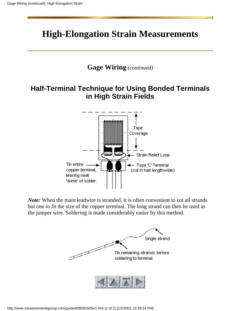
Relatively high displacements occur with high-elongation strain measurements,suggesting the use of an external terminal strip. The strain gage should be wired tothe terminal strip with a small-diameter, single-conductor wire no larger than 30AWG (0.25 mm diameter) as shown on the following page. Drafting tape(Micro-Measurements M-LINE PDT-1) applied over the gage during soldering isrecommended to restrict the flow of solder to the tab ends.
Adequate strain relief loops, as shown in the illustration on the following page, areof particular importance in high-elongation measurements. Note also that the leadsattached to the strain gage tabs approach in a direction 90 degrees from themaximum principal strain axis.
After soldering, all tape and soldering flux should be removed with several brushapplications of rosin solvent (Micro-Measurements M-LINE RSK-1).
Page 9 of 17
Gage Wiring: High-Elongation Strain
http://www.measurementsgroup.com/guide/tt/tt605/605e.htm [1/2/2001 12:39:23 PM]
High-Elongation Strain Measurements
Gage Wiring (continued)
Half-Terminal Technique for Using Bonded Terminalsin High Strain Fields
Note: When the main leadwire is stranded, it is often convenient to cut all strandsbut one to fit the size of the copper terminal. The long strand can then be used asthe jumper wire. Soldering is made considerably easier by this method.
Gage Wiring (continued): High-Elongation Strain
http://www.measurementsgroup.com/guide/tt/tt605/605e1.htm (1 of 2) [1/2/2001 12:39:24 PM]

Page 10 of 17
Gage Wiring (continued): High-Elongation Strain
http://www.measurementsgroup.com/guide/tt/tt605/605e1.htm (2 of 2) [1/2/2001 12:39:24 PM]
High-Elongation Strain Measurements
Protective Coating Selection
When selecting a protective coating, it is necessary to consider the flexibility aswell as the environmental capabilities of the coating. M-Coats A, C, F, 3140 and3145 are adequately flexible for most high-elongation strain measurements. Aselection chart for environmental considerations is provided.
Page 11 of 17
Protective Coating Selection: High-Elongation Strain
http://www.measurementsgroup.com/guide/tt/tt605/605f.htm [1/2/2001 12:39:24 PM]
High-Elongation Strain Measurements
Gage Linearity
A discussion of high-elongation strain gage measurements is not complete withoutincluding the subject of gage linearity under plastic straining conditions.
Although constantan alloy is one of the most linear of all strain gage alloys, it doesexhibit small changes in gage factor during high elongation.
Without treating this subject in detail, it can be shown in theory that the gage factorof the strain gage approaches a value of 2 + when the gage alloy is strainedbeyond its elastic range. The elastic range for constantan is approximately 0.5%.
Using the 2 + strain guideline, the gage factor at a strain level of 10% would beclose to 2.1 in tension and 1.9 in compression. At a 20% strain level, the gagefactor approaches 2.2 in tension and 1.8 in compression.
While these numbers are correct in theory, they have not, to our knowledge, beensubstantiated by actual test results.
Page 12 of 17
Gage Linearity: High-Elongation Strain
http://www.measurementsgroup.com/guide/tt/tt605/605g.htm [1/2/2001 12:39:25 PM]
High-Elongation Strain Measurements
Instrumentation
Wheatstone bridge circuits are commonly used in strain gage measurements. Thesecircuits are inherently nonlinear when large gage resistance changes areencountered. Consult Measurements Group Tech Note TN-507, Errors Due toWheatstone Bridge Nonlinearity, for correction procedures.
Page 13 of 17
Instrumentation: High-Elongation Strain
http://www.measurementsgroup.com/guide/tt/tt605/605h.htm [1/2/2001 12:39:25 PM]
High-Elongation Strain Measurements
Common Installation Problems
Unbonding of the Gage
Assuming the proper adhesive has been selected (see reference table), loss of bondbefore maximum gage elongation is reached can usually be traced to acontaminated or improperly prepared surface. A visual examination of the bondarea will usually detect this. Cured adhesive on the back of the strain gage but noton the specimen generally indicates improper or incomplete surface preparation.
It is important to note that some materials, like polyethylene, are difficult to bond;and it will not be possible to reach maximum gage elongation before bond failure.
Page 14 of 17
Unbonding of the Gage: Common Installation Problems
http://www.measurementsgroup.com/guide/tt/tt605/605i.htm [1/2/2001 12:39:25 PM]
High-Elongation Strain Measurements
Common Installation Problems
Unbonding of the Gage Tabs
Gage tab unbonding is often due to an excessive amount of solder, whichreinforces the gage tabs, and causes them to unbond as a result of their inflexibility.Drafting tape is recommended for restricting the amount of solder (see GageWiring).
Excessive soldering temperatures, or terminals placed too close to gage tabs, canalso contribute to this problem.
Page 15 of 17
Unbonding of the Gage Tabs: Common Installation Problems
http://www.measurementsgroup.com/guide/tt/tt605/605i1.htm [1/2/2001 12:39:26 PM]
High-Elongation Strain Measurements
Common Installation Problems
Gage Grid Failure (Open Circuit)
Assuming that the strain gage readings were within the strain range capability ofthe gage, and that the backing remains bonded, premature grid failures are often theresult of high local strains within the area covered by the gage. Since the straingage is an averaging device, it will indicate average strain along its grid length.Steep strain gradients can cause localized excessive strain damage while the gagemay have been indicating a strain that was well within its elongation limits.
Grid failures may also result from strain concentrations caused by inclusions in theadhesive layer (unmixed adhesive particles, dirt, etc.) or by uneven gluelines, oftencaused by irregular or pitted specimen surfaces or uneven clamping pressures.
Page 16 of 17
Gage Grid Failure (Open Circuit): Common Installation Problems
http://www.measurementsgroup.com/guide/tt/tt605/605i2.htm [1/2/2001 12:39:26 PM]
High-Elongation Strain Measurements
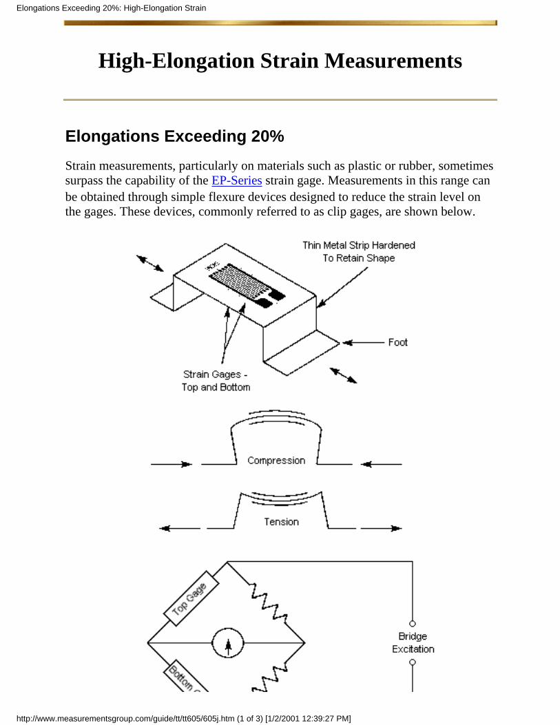
Elongations Exceeding 20%
Strain measurements, particularly on materials such as plastic or rubber, sometimessurpass the capability of the EP-Series strain gage. Measurements in this range canbe obtained through simple flexure devices designed to reduce the strain level onthe gages. These devices, commonly referred to as clip gages, are shown below.
Elongations Exceeding 20%: High-Elongation Strain
http://www.measurementsgroup.com/guide/tt/tt605/605j.htm (1 of 3) [1/2/2001 12:39:27 PM]
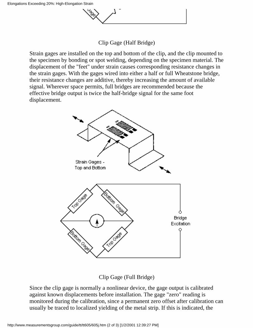
Clip Gage (Half Bridge)
Strain gages are installed on the top and bottom of the clip, and the clip mounted tothe specimen by bonding or spot welding, depending on the specimen material. Thedisplacement of the "feet" under strain causes corresponding resistance changes inthe strain gages. With the gages wired into either a half or full Wheatstone bridge,their resistance changes are additive, thereby increasing the amount of availablesignal. Wherever space permits, full bridges are recommended because theeffective bridge output is twice the half-bridge signal for the same footdisplacement.
Clip Gage (Full Bridge)
Since the clip gage is normally a nonlinear device, the gage output is calibratedagainst known displacements before installation. The gage "zero" reading ismonitored during the calibration, since a permanent zero offset after calibration canusually be traced to localized yielding of the metal strip. If this is indicated, the
Elongations Exceeding 20%: High-Elongation Strain
http://www.measurementsgroup.com/guide/tt/tt605/605j.htm (2 of 3) [1/2/2001 12:39:27 PM]

calibration should be repeated several times to check for reproducibility.
A clip gage is particularly useful in measuring very large specimen strains or actualdisplacements occurring between two bodies, as with expansion joints or crackopenings.
Page 17 of 17
Elongations Exceeding 20%: High-Elongation Strain
http://www.measurementsgroup.com/guide/tt/tt605/605j.htm (3 of 3) [1/2/2001 12:39:27 PM]
High-Elongation Strain MeasurementsRecommended M-LINE Adhesives
See Micro-Measurements Catalog A-110 for complete specifications.
M-Bond 200
General DescriptionSpecial pretested grade of cyanoacrylate, certified for strain gage use. Fastroom-temperature cure.
Preferred Cure3 min at +75 deg F (+24 deg C)
Elongation Capabilities+75 deg F (+24 deg C) 6% (up to 15% for installations less than 30 minutesold)
●
Reference Table
M-Bond 200 (reference table): High-Elongation Strain
http://www.measurementsgroup.com/guide/tt/tt605/605b1.htm [1/2/2001 12:39:20 PM]

High-Elongation Strain MeasurementsRecommended M-LINE Adhesives
See Micro-Measurements Catalog A-110 for complete specifications.
M-Bond AE-10
General DescriptionTwo-component, 100%-solids epoxy system. Capable of room-temperature cure.Transparent, medium-viscosity adhesive.
Preferred Cure6 hours at +75 deg F (+24 deg C)
Elongation Capabilities-320 deg F (-195 deg C) 1%●
+75 deg F (+24 deg C) 6 - 10%●
+200 deg F (+95 deg C) 10 -15%●
Reference Table
M-Bond AE-10 (reference table): High-Elongation Strain
http://www.measurementsgroup.com/guide/tt/tt605/605b2.htm [1/2/2001 12:39:20 PM]
High-Elongation Strain MeasurementsRecommended M-LINE Adhesives
See Micro-Measurements Catalog A-110 for complete specifications.
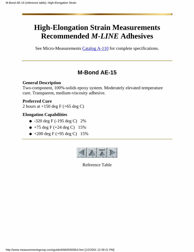
M-Bond AE-15
General DescriptionTwo-component, 100%-solids epoxy system. Moderately elevated temperaturecure. Transparent, medium-viscosity adhesive.
Preferred Cure2 hours at +150 deg F (+65 deg C)
Elongation Capabilities-320 deg F (-195 deg C) 2%●
+75 deg F (+24 deg C) 15%●
+200 deg F (+95 deg C) 15%●
Reference Table
M-Bond AE-15 (reference table): High-Elongation Strain
http://www.measurementsgroup.com/guide/tt/tt605/605b3.htm [1/2/2001 12:39:21 PM]
High-Elongation Strain MeasurementsRecommended M-LINE Adhesives
See Micro-Measurements Catalog A-110 for complete specifications.
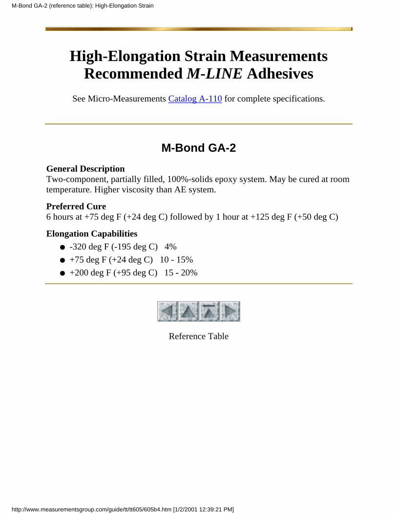
M-Bond GA-2
General DescriptionTwo-component, partially filled, 100%-solids epoxy system. May be cured at roomtemperature. Higher viscosity than AE system.
Preferred Cure6 hours at +75 deg F (+24 deg C) followed by 1 hour at +125 deg F (+50 deg C)
Elongation Capabilities-320 deg F (-195 deg C) 4%●
+75 deg F (+24 deg C) 10 - 15%●
+200 deg F (+95 deg C) 15 - 20%●
Reference Table
M-Bond GA-2 (reference table): High-Elongation Strain
http://www.measurementsgroup.com/guide/tt/tt605/605b4.htm [1/2/2001 12:39:21 PM]
High-Elongation Strain MeasurementsRecommended M-LINE Adhesives
See Micro-Measurements Catalog A-110 for complete specifications.
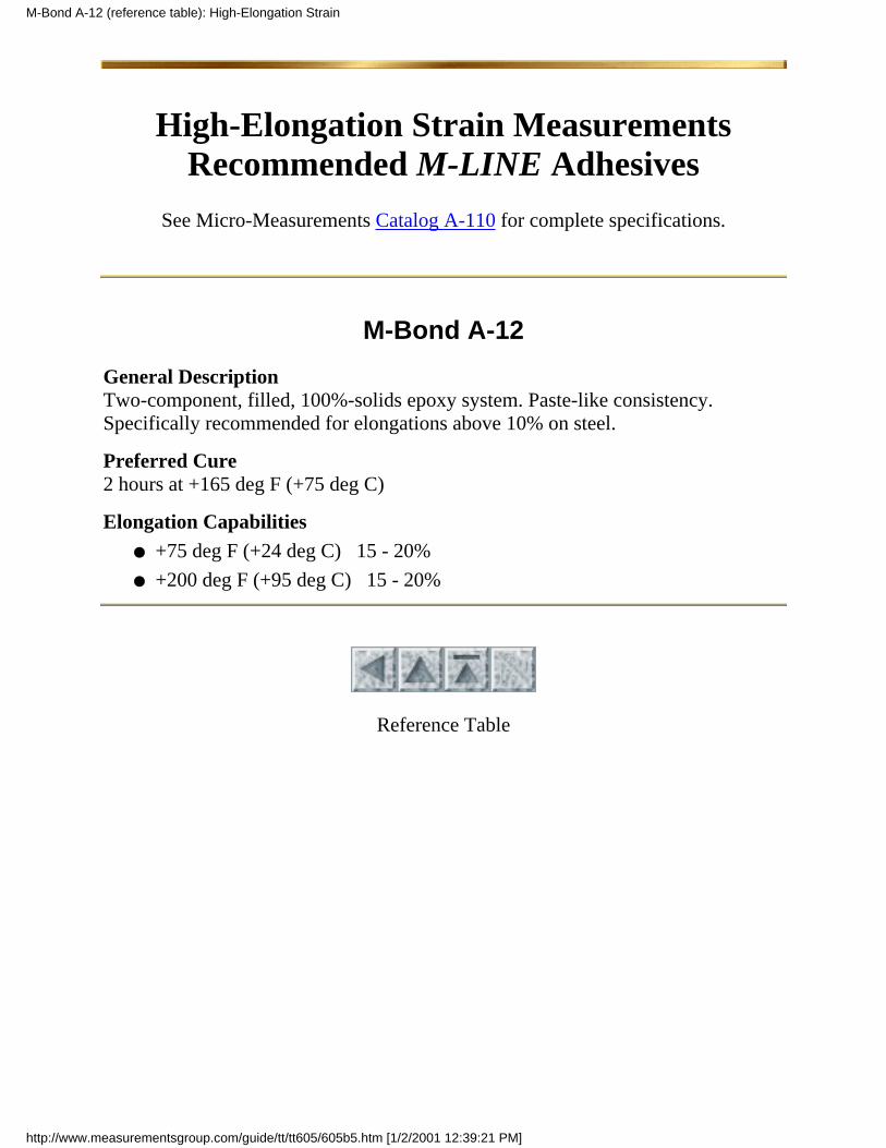
M-Bond A-12
General DescriptionTwo-component, filled, 100%-solids epoxy system. Paste-like consistency.Specifically recommended for elongations above 10% on steel.
Preferred Cure2 hours at +165 deg F (+75 deg C)
Elongation Capabilities+75 deg F (+24 deg C) 15 - 20%●
+200 deg F (+95 deg C) 15 - 20%●
Reference Table
M-Bond A-12 (reference table): High-Elongation Strain
http://www.measurementsgroup.com/guide/tt/tt605/605b5.htm [1/2/2001 12:39:21 PM]