indian railways chittaranjan locomotive works … · the dual mode shunting locomotive is basically...
TRANSCRIPT
Page 1 of 47
SPECIFICATION FOR BATTERY OPERATED DUAL
MODE SHUNTING LOCOMOTIVE(DMSL), Alt. 0
PREP.BY. SSE/D&D
CHECKED .BY SEE/D&D
CENTRE FOR DESIGN & DEVELOPMENT CHITTARANJAN LOCOMOTIVE WORKS
NO: CLW/C-D&D/ES/03/0551
ISSUED BY DY. CEE/D&D Alt.
INDIAN RAILWAYS
CHITTARANJAN LOCOMOTIVE WORKS CHITTARANJAN
SPECIFICATION FOR BATTERY OPERATED
DUAL MODE SHUNTING LOCOMOTIVE (DMSL)
SPECIFICATION NO - CLW/C-D&D/ES/03/0553, Alt.- 0
Total no. of pages: 47
(Issued on August– 2019)
Page 2 of 47
SPECIFICATION FOR BATTERY OPERATED DUAL
MODE SHUNTING LOCOMOTIVE(DMSL), Alt. 0
PREP.BY. SSE/D&D
CHECKED .BY SEE/D&D
CENTRE FOR DESIGN & DEVELOPMENT CHITTARANJAN LOCOMOTIVE WORKS
NO: CLW/C-D&D/ES/03/0551
ISSUED BY DY. CEE/D&D Alt.
ALTERATION RECORD SHEET
Amendmentin Clause No.
Date of amendment
Page No.
Alteration Changes
-
-
-
-
-
-
-
-
Page 3 of 47
SPECIFICATION FOR BATTERY OPERATED DUAL
MODE SHUNTING LOCOMOTIVE(DMSL), Alt. 0
PREP.BY. SSE/D&D
CHECKED .BY SEE/D&D
CENTRE FOR DESIGN & DEVELOPMENT CHITTARANJAN LOCOMOTIVE WORKS
NO: CLW/C-D&D/ES/03/0551
ISSUED BY DY. CEE/D&D Alt.
TABLE OF CONTENTS
Chapter No.
Description Page
Abbreviations and Definitions 4-5
1 General 6-13
2 Technical Requirement 14-23
3 Operating and Environmental Conditions 24-25
4 Scope of work/supply 26-28
5 General Conditions, Inspection, Test & Trials and Other requirements 29-35
6 Salient information for locomotive
Annexure-I to Annexure-X
36-47
6.0 Annexure-I: Schematic circuit diagram of Power & Auxiliary Circuit 36
6.1 Annexure-II:WAG-9 Cab structure 37
6.2 Annexure-III: Machine Room layout of WAG-9 38
6.3 Annexure-IV: Machine Room layout of WAP-7 39
6.4 Annexure-V: Max. & Min. Moving dimension for BG Electric locomotive 40
6.5 Annexure-VI: Existing Bogie frame of WAG-9 locomotive 41
6.6 Annexure-VII: Salient information of existing Main Transformer 42
6.7 Annexure-VIII: Details of existing Series Resonant Inductor unit 43
6.8 Annexure-VIII: Details of existing Auxiliary Converter Choke unit 43
6.9 Annexure-IX: Characteristics of existing Traction Motor 44
6.10 Annexure-X: Existing load distribution of Auxiliary Converter 45-46
6.11 Annexure-XI: Performance curve for Battery mode operation 47
6.12 Annexure-XI: Performance curve for OHE mode operation 47
Page 4 of 47
SPECIFICATION FOR BATTERY OPERATED DUAL
MODE SHUNTING LOCOMOTIVE(DMSL), Alt. 0
PREP.BY. SSE/D&D
CHECKED .BY SEE/D&D
CENTRE FOR DESIGN & DEVELOPMENT CHITTARANJAN LOCOMOTIVE WORKS
NO: CLW/C-D&D/ES/03/0551
ISSUED BY DY. CEE/D&D Alt.
Abbreviations and Definitions:
AAR - Association of American Railroad
AC - Alternating current
AF - Audio frequency
Aux - Auxiliaries BG - shall mean 1676 mm Broad Gauge used in IR BMS -Battery Management System
BOM - Bill of Material
BS -British Standards
CBC -Centre Buffer Coupler
CLW - Chittaranjan Locomotive Works
Co-Co -Shall mean one unit of the Locomotive consisting of two bogies, witheach bogie having three wheels with three independent traction motors and the traction motor drive coupled to each wheel;
CON - Converter
DC -Direct Current
DCU - Drive Control Unit
DMSL -Dual mode shunting locomotive
EMC -Electro-magnetic Compatibility
EMI -Electro-magnetic Interference
EN -Euro Norm (European Standards)
FEM -Finite Element Method
FLG - Fahrzeuleltgert (German) – Engl.
GPS -Global Positioning System
GSM -Global System for Mobile
GSM-R -Global System for Mobile- Railways
GTO - Gate Turn OffThyristor
HB - Auxiliary circuit cubicle
HT -High Tension (Voltage) (according to Indian Electricity Rules)
IC -Integrated Circuit
IEC -International Electro technical Commission
IEEE -Institution of Electrical and Electronic Engineers
IGBT -Insulated Gate Bipolar Transistor
IVC - Inter Vehicular Couplers
Inspecting Officer -The person, firm or department nominated to inspect the converters or the representative of the inspecting officer so nominated.
IR - Indian Railways
IRS - Indian Railways Standards
IS -Indian Standard
ISO -International Standard Organization
LED -Light Emitting Diode
MCB - Miniature Circuit Breaker
MMD -Maximum Moving Dimension
MMI -Man Machine Interface
MSU -Motor Suspension Unit
OEM - Original Equipment Manufacturer - Original Equipment Manufacturer
OHE -Over Head Equipment
Page 5 of 47
SPECIFICATION FOR BATTERY OPERATED DUAL
MODE SHUNTING LOCOMOTIVE(DMSL), Alt. 0
PREP.BY. SSE/D&D
CHECKED .BY SEE/D&D
CENTRE FOR DESIGN & DEVELOPMENT CHITTARANJAN LOCOMOTIVE WORKS
NO: CLW/C-D&D/ES/03/0551
ISSUED BY DY. CEE/D&D Alt.
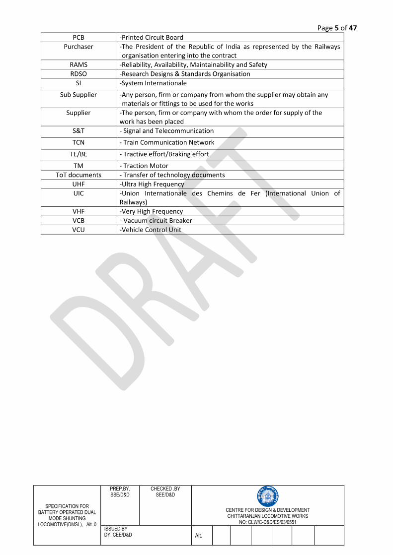
PCB -Printed Circuit Board
Purchaser -The President of the Republic of India as represented by the Railways organisation entering into the contract
RAMS -Reliability, Availability, Maintainability and Safety
RDSO -Research Designs & Standards Organisation
SI -System Internationale
Sub Supplier -Any person, firm or company from whom the supplier may obtain any materials or fittings to be used for the works
Supplier -The person, firm or company with whom the order for supply of the work has been placed
S&T - Signal and Telecommunication
TCN - Train Communication Network
TE/BE - Tractive effort/Braking effort
TM - Traction Motor
ToT documents - Transfer of technology documents
UHF -Ultra High Frequency
UIC -Union Internationale des Chemins de Fer (International Union of Railways)
VHF -Very High Frequency
VCB - Vacuum circuit Breaker
VCU -Vehicle Control Unit
Page 6 of 47
SPECIFICATION FOR BATTERY OPERATED DUAL
MODE SHUNTING LOCOMOTIVE(DMSL), Alt. 0
PREP.BY. SSE/D&D
CHECKED .BY SEE/D&D
CENTRE FOR DESIGN & DEVELOPMENT CHITTARANJAN LOCOMOTIVE WORKS
NO: CLW/C-D&D/ES/03/0551
ISSUED BY DY. CEE/D&D Alt.
CHAPTER - 1: GENERAL
1.0 This specification deals with the design, development, supply, installation, commissioning and field validation of Dual Mode Shunting Locomotive (DMSL) for passenger coaches for Indian Railways. It is intended to define the technical requirements of additional equipment namely Integrated converter, battery bank, modified shell assembly etc for the shunting locomotive which will be utilized for shunting purpose in urban station area.
1.1 Shunting operations are performed using diesel locomotives, although the tracks in the major stations are electrified including platforms. However the coaching depots and yards are not 100% electrified. Due to this bottleneck the shunting operation requires deployment of diesel locomotives as the complete shunting zone is non-electrified. In additional to thus the washing pits of coaching depots can’t be electrified for safety reasons. These are the general forcing factors for using diesel locomotives for shunting. Diesel locomotive has some inherent disadvantages such as: noise and air pollution which is not desirable especially in major urban stations. Thus it is conceived that a shunting locomotive can be developed with battery backup to do the shunting operations in place of diesel shunting locomotives. During the small non-electrified sections of shunting zone these locomotive will be powered from battery. As soon asthe OHE shall be available the normal 25kVsupply will be utilized. The Dual Mode Shunting Locomotive is basically an electric locomotive with the ability to operate from 25kV AC OHE supply as well as battery set. This specification defines the system and performance requirement for design, development, construction and development of battery operated dual mode shunting locomotive.
1.2 Tangible benefits of Dual Mode Shunting Locomotives: summarized as follows:
1.2.1 Emission free and noise free shunting is the prime concern in urban station area like Delhi, Mumbai, Howrah, Chennai, and Bangalore.
1.2.2 Dependency on diesel locos will not be there. Further, the populations of diesel locos are decreasing as the same are being phased out for various reasons.
1.2.3 In the event of major accident and natural calamities where OHE gets affected, DMSL may provide operational flexibility to work on battery mode during the emergency condition until normal condition is restored.
1.3 The purpose of the specification is to provide the technical specification for integration of Li-ion battery with the propulsion equipment. The responsibility of Railways and Firm are mentioned in the subsequent clauses in the specification in Chapter-4.
1.4 The proven/suitably designed propulsion system (Integrated converter) shall be used in the project and the battery shall be integrated on the DC link of the power converter. Supplier should take necessary approval of modifications carried out during design stage.
1.5 The environmental and service conditions, performance requirements and technical requirements are specified in these Specifications and Standards.
1.6 The design and manufacture of the equipments shall be based on the requirements set out in these Specifications and Standards and in accordance with Good Industry Practice.
Page 7 of 47
SPECIFICATION FOR BATTERY OPERATED DUAL
MODE SHUNTING LOCOMOTIVE(DMSL), Alt. 0
PREP.BY. SSE/D&D
CHECKED .BY SEE/D&D
CENTRE FOR DESIGN & DEVELOPMENT CHITTARANJAN LOCOMOTIVE WORKS
NO: CLW/C-D&D/ES/03/0551
ISSUED BY DY. CEE/D&D Alt.
1.7 The Contractor shall demonstrate, to the satisfaction of the IR, that the sub-systems proposed to be used in the Locomotives are based on proven technology and design. For the avoidance of doubt, the IR may require the contractor to conduct such tests and trials as may be necessary to establish the reliability and efficiency of such technology and designs in accordance with the Good Industry Practice.
1.8 Due consideration shall be given at design stage to ambient conditions of dust, moisture, high temperature and vibrations prevalent in India as specified in Chapter-3 in this specifications and standards.
1.9 The validation, test and trials of the locomotive, its sub-component under the scope of supply shall be done up to the expectation level of IR. The detailed chapter-5 may be referred for this purpose.
1.10 References to various standards
1.10.1 The standards applicable and relevant to the complete Locomotive and to the various sub systems and systems shall be:
i. IEC publications; ii. EN;
iii. UIC; iv. AAR; v. IEEE;
vi. BS; vii. IS;
viii. TSI; ix. Any other standards referred to in these specifications and standards.
In the event of any contradiction in the aforesaid standards, the following standards shall have priority in the order listed:
i. Standards mentioned in Specifications and Standards set forth herein; ii. EN /IEC/UIC/AAR; and
iii. IS.
For avoidance of any doubt, in case of any conflict between the requirements of these standards, the stipulations of these Specification and Standards shall have precedence.
1.10.2 The design of the upgraded equipment, system and sub-systems there of shall comply with
the following standards
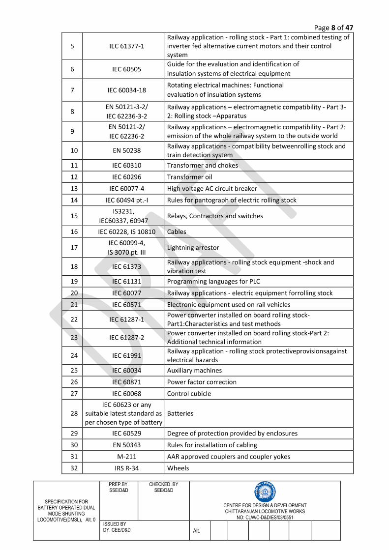
SN Standards Title
1 IEC 61133 Electric traction - rolling stock - test methods forelectric and thermal /electric rolling stock oncompletion of construction and before entry into service
2 IEC 61287 Electronic equipment used on rail vehicles
3 IEC 60571 Specific rules concerning the electronic control part of converters.
4 IEC 60349 -2 Electronic converter fed alternating currentmotors
Page 8 of 47
SPECIFICATION FOR BATTERY OPERATED DUAL
MODE SHUNTING LOCOMOTIVE(DMSL), Alt. 0
PREP.BY. SSE/D&D
CHECKED .BY SEE/D&D
CENTRE FOR DESIGN & DEVELOPMENT CHITTARANJAN LOCOMOTIVE WORKS
NO: CLW/C-D&D/ES/03/0551
ISSUED BY DY. CEE/D&D Alt.
5 IEC 61377-1 Railway application - rolling stock - Part 1: combined testing of inverter fed alternative current motors and their control system
6 IEC 60505 Guide for the evaluation and identification of insulation systems of electrical equipment
7 IEC 60034-18 Rotating electrical machines: Functional evaluation of insulation systems
8 EN 50121-3-2/
IEC 62236-3-2
Railway applications – electromagnetic compatibility - Part 3-2: Rolling stock –Apparatus
9 EN 50121-2/
IEC 62236-2
Railway applications – electromagnetic compatibility - Part 2: emission of the whole railway system to the outside world
10 EN 50238 Railway applications - compatibility betweenrolling stock and train detection system
11 IEC 60310 Transformer and chokes
12 IEC 60296 Transformer oil
13 IEC 60077-4 High voltage AC circuit breaker
14 IEC 60494 pt.-I Rules for pantograph of electric rolling stock
15 IS3231,
IEC60337, 60947 Relays, Contractors and switches
16 IEC 60228, IS 10810 Cables
17 IEC 60099-4,
IS 3070 pt. III Lightning arrestor
18 IEC 61373 Railway applications - rolling stock equipment -shock and vibration test
19 IEC 61131 Programming languages for PLC
20 IEC 60077 Railway applications - electric equipment forrolling stock
21 IEC 60571 Electronic equipment used on rail vehicles
22 IEC 61287-1 Power converter installed on board rolling stock- Part1:Characteristics and test methods
23 IEC 61287-2 Power converter installed on board rolling stock-Part 2: Additional technical information
24 IEC 61991 Railway application - rolling stock protectiveprovisionsagainst electrical hazards
25 IEC 60034 Auxiliary machines
26 IEC 60871 Power factor correction
27 IEC 60068 Control cubicle
28 IEC 60623 or any
suitable latest standard as per chosen type of battery
Batteries
29 IEC 60529 Degree of protection provided by enclosures
30 EN 50343 Rules for installation of cabling
31 M-211 AAR approved couplers and coupler yokes
32 IRS R-34 Wheels
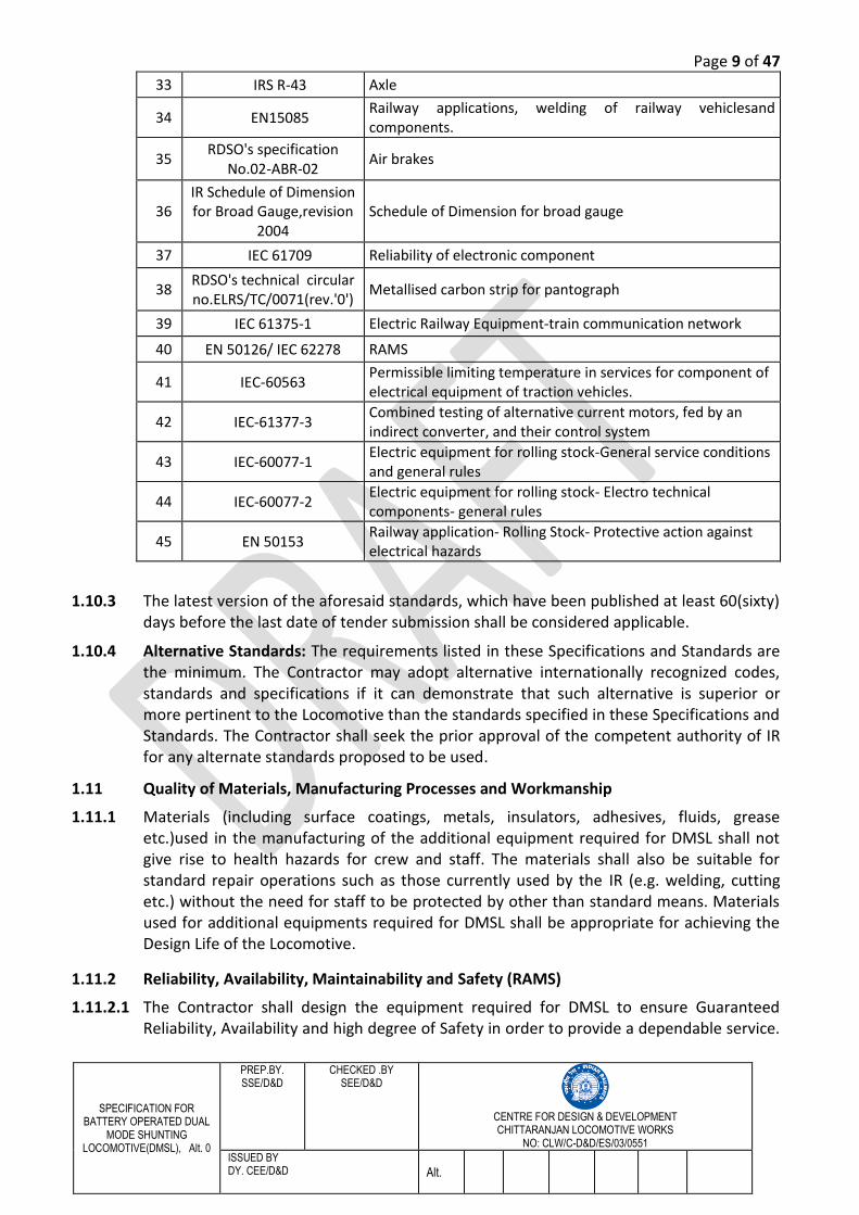
Page 9 of 47
SPECIFICATION FOR BATTERY OPERATED DUAL
MODE SHUNTING LOCOMOTIVE(DMSL), Alt. 0
PREP.BY. SSE/D&D
CHECKED .BY SEE/D&D
CENTRE FOR DESIGN & DEVELOPMENT CHITTARANJAN LOCOMOTIVE WORKS
NO: CLW/C-D&D/ES/03/0551
ISSUED BY DY. CEE/D&D Alt.
33 IRS R-43 Axle
34 EN15085 Railway applications, welding of railway vehiclesand components.
35 RDSO's specification
No.02-ABR-02 Air brakes
36 IR Schedule of Dimension for Broad Gauge,revision
2004 Schedule of Dimension for broad gauge
37 IEC 61709 Reliability of electronic component
38 RDSO's technical circular no.ELRS/TC/0071(rev.'0')
Metallised carbon strip for pantograph
39 IEC 61375-1 Electric Railway Equipment-train communication network
40 EN 50126/ IEC 62278 RAMS
41 IEC-60563 Permissible limiting temperature in services for component of electrical equipment of traction vehicles.
42 IEC-61377-3 Combined testing of alternative current motors, fed by an indirect converter, and their control system
43 IEC-60077-1 Electric equipment for rolling stock-General service conditions and general rules
44 IEC-60077-2 Electric equipment for rolling stock- Electro technical components- general rules
45 EN 50153 Railway application- Rolling Stock- Protective action against electrical hazards
1.10.3 The latest version of the aforesaid standards, which have been published at least 60(sixty) days before the last date of tender submission shall be considered applicable.
1.10.4 Alternative Standards: The requirements listed in these Specifications and Standards are
the minimum. The Contractor may adopt alternative internationally recognized codes, standards and specifications if it can demonstrate that such alternative is superior or more pertinent to the Locomotive than the standards specified in these Specifications and Standards. The Contractor shall seek the prior approval of the competent authority of IR for any alternate standards proposed to be used.
1.11 Quality of Materials, Manufacturing Processes and Workmanship
1.11.1 Materials (including surface coatings, metals, insulators, adhesives, fluids, grease etc.)used in the manufacturing of the additional equipment required for DMSL shall not give rise to health hazards for crew and staff. The materials shall also be suitable for standard repair operations such as those currently used by the IR (e.g. welding, cutting etc.) without the need for staff to be protected by other than standard means. Materials used for additional equipments required for DMSL shall be appropriate for achieving the Design Life of the Locomotive.
1.11.2 Reliability, Availability, Maintainability and Safety (RAMS)
1.11.2.1 The Contractor shall design the equipment required for DMSL to ensure Guaranteed Reliability, Availability and high degree of Safety in order to provide a dependable service.
Page 10 of 47
SPECIFICATION FOR BATTERY OPERATED DUAL
MODE SHUNTING LOCOMOTIVE(DMSL), Alt. 0
PREP.BY. SSE/D&D
CHECKED .BY SEE/D&D
CENTRE FOR DESIGN & DEVELOPMENT CHITTARANJAN LOCOMOTIVE WORKS
NO: CLW/C-D&D/ES/03/0551
ISSUED BY DY. CEE/D&D Alt.
The optimization of the system with respect to Reliability, Availability, Maintainability and Safety shall form an integral element of these Specifications and Standards.
1.11.2.2 The plan for Reliability, Availability, Maintainability and Safety shall conform to EN 50126/ IEC 62278. Reliability of electronic components shall conform to IEC 61709.
1.11.2.3 The Contractor shall develop RAMS targets both for the complete system and for the major sub-systems such as transformer, traction converter, auxiliary converter, electronics, traction motor, Transmission and Suspension System, Battery, high voltage equipments, blowers and other auxiliary machines, such that it will provide a high level of dependability.
1.11.2.4 There shall be an efficient means of operation of the locomotive after all failures in accordance with Good Industry Practice.
1.11.2.5 Components critical for safety shall fall into safe operating mode in case of malfunctioning. The system safety plan shall identify and list safety critical components and this list shall be updated periodically.
1.11.2.6 The Contractor shall establish and operate a detailed Reliability, Availability, maintainability and Safety (RAMS) Assessment system in support of the design, manufacture and subsequent testing, commissioning, operation and maintenance of the Locomotives.
1.12 Infringement of patent rights: Indian Railway shall not be responsible for infringement of patent rights arising due to similarity in design, manufacturing process, components used in design, development and manufacturing of DMSL and any other factor, which may be cause of such dispute. The responsibility to settle any issue lies with the manufacturer.
1.13 Documentation: Following documents shall be submitted by the supplier along with the offer for evaluation:
1.13.1 Schematic circuit: - Functional description; - System design concept; - Communication protocol and software structure description along with compatibility
with the locomotive control system; - Cooling System design; - Mechanical interface diagram and compliance to existing mechanics; - Clause by clause compliance of this specification; - Credentials with details of supply made of similar items; - Data sheets for devices and other equipment proposed along with detailed
description of supply proposed; - Thermal calculation of power devices; - Salient features and advantages of the offered system; - Details of technical support and training offered, the training shall cover on
assembly, testing, commissioning, operation, maintenance and repair to IR personnel and training shall also cover in software parameter settings, fault diagnostic and analysis;
- Recommended list of spares for 3-year maintenance after warranty along with full drawing/design and details of OEM;
Page 11 of 47
SPECIFICATION FOR BATTERY OPERATED DUAL
MODE SHUNTING LOCOMOTIVE(DMSL), Alt. 0
PREP.BY. SSE/D&D
CHECKED .BY SEE/D&D
CENTRE FOR DESIGN & DEVELOPMENT CHITTARANJAN LOCOMOTIVE WORKS
NO: CLW/C-D&D/ES/03/0551
ISSUED BY DY. CEE/D&D Alt.
- List of special tools, jigs and fixtures needed for assembly, testing, commissioning, maintenance and repair along with full technical specifications and probable suppliers;
- Logistics proposed for warranty support within India; - Declaration for long-term support by the supplier; and - IRIS/ISO 9001 certifications
1.13.2 The Supplier shall submit the design details, including but not limited to the following, to CLW before commencing manufacturing. Production should begin only after approval from IR in written form:
- Technical documentation explaining the complete scheme, characteristics, diagnostics, protection and control etc.;
- Detailed drawings of each system/sub-system with interface details; - Design calculations for selection of devices, cooling systems and various subsystems,
establishing the adequacy of the components selected; - Complete BOM / technical specification of components with source of supply; - Cooling system design description, data and cooling fluid data; - Mechanical drawings, mounting arrangement, weight, details of mounting
accessories; - Procedure for parameter alteration, software downloading, diagnostic uploading,
analysis etc.; - Schedule maintenance activities with periodicity; - Maintenance, trouble shooting and repair manual in soft form & hard copy; - Guaranteed values of efficiency of devices/subassemblies and assemblies; - Calculation to withstand short circuit current under fault conditions; - Details of short time rating of the integrated converter; - Expected efficiency with respect to vehicle load/speed along with calculations; - Calculation and simulation results of system behavior, including interference to the
S&T circuits; - All calculations evaluated on the basis of software simulations shall be supported by
sample calculations; and shall details of tools and plants with design/drawings and supplies.
- The 3D models of all the cubicles, compatible to NX platform.
Approval of design means approval of general design features. Notwithstanding the approval, the Supplier shall wholly and completely be responsible for the performance of the complete equipment.
1.14 Warranty: The supplier shall warranty that everything to be furnished under the contract shall be free from defects and faults in design, material, workmanship and manufacture, and shall be of the highest grade and consistent with the established and generally accepted standards for stores of the type ordered and in full conformity with the contract and samples, if any, and shall, if operate properly according to the contract.
The warranty for the items to be supplied under this contract shall be 72months from delivery or 60 months from the date of satisfactory commissioning and acceptance tests of the items whichever is earlier. The supplier shall immediately, on receipt of notice of defect, depute firms engineer to start action for rectification of defects under warranty.
Page 12 of 47
SPECIFICATION FOR BATTERY OPERATED DUAL
MODE SHUNTING LOCOMOTIVE(DMSL), Alt. 0
PREP.BY. SSE/D&D
CHECKED .BY SEE/D&D
CENTRE FOR DESIGN & DEVELOPMENT CHITTARANJAN LOCOMOTIVE WORKS
NO: CLW/C-D&D/ES/03/0551
ISSUED BY DY. CEE/D&D Alt.
In the eventuality of major design modifications during the currency of the warranty period, the warranty for such period as is mutually agreed.
1.15 Supplier’s responsibility: The supplier’s shall supply the materials as per the scope of work mentioned in this specification. Other minor items and its scope of supply shall be decided during design approval stage which would have meager financial implication. The responsibility shall be extended to the following:
a. The supplier shall design, evaluate, examine, and validate all the equipment in the scope of supply of the tender. The ultimate responsibility of the performance of this equipment vis-a-vis performance of the Dual Mode Shunting locomotive shall lie with the supplier only.
b. The supplier shall supply detailed instructions for proper installation and commissioning of the equipments in the scope of this specification on the DMSL. For this purpose, the supplier shall also depute their representative during installation and commissioning of the equipments, supplied against the specification.
c. The supplier shall arrange to carry out detailed test & performance proving, jointly with CLW.
d. The supplier shall also quote for special tools, testing jigs, and instruments, which may be required for troubleshooting and maintenance of the equipment supplied. The design shall be developed as per requirement given in the specification.
e. The supplier shall also quote for Annual Maintenance Contract (AMC) for equipments supplied against this specification.
f. The supplier shall supply suitable software for off-line analysis of diagnostic data downloaded from the converter and control electronics.
g. Contractor shall perform necessary simulation and analysis including FEM analysis and load analysis, running dynamics etc. in simulation mode on modified equipments to be supplied against the specification. Test results should be within acceptable limits in light of enhanced rating of equipments on existing locomotive. The test results with observations, if any, shall be submitted with the design document.
h. Integration& testing/validation of additional equipments with the locomotive shall be under Contractor’s scope of work. Contractor shall also associate themselves during the field trial of first locomotive.
i. Contractor should submit all the design details covering modified items, their mounting & integration details, wiring diagram etc. in hard and soft copy to IR.
j. Contractor shall submit all the Characteristics curves specified in the specification such as Power, Torque, current, power factor, stator & rotor frequency, voltage etc. with respect to speed(rpm).
k. Contractor shall submit the complete scheme for fitment of newly designed three phase traction motor in the bogie of WAG-9H platform.
l. Supplier should take necessary approval of modification during the design approval stage.
m. Performance Curves: The preliminary throttle-wise "Tractive Effort Vs Speed" & 'Braking EffortVs Speed' at standard as well as site conditions shall be submitted
Page 13 of 47
SPECIFICATION FOR BATTERY OPERATED DUAL
MODE SHUNTING LOCOMOTIVE(DMSL), Alt. 0
PREP.BY. SSE/D&D
CHECKED .BY SEE/D&D
CENTRE FOR DESIGN & DEVELOPMENT CHITTARANJAN LOCOMOTIVE WORKS
NO: CLW/C-D&D/ES/03/0551
ISSUED BY DY. CEE/D&D Alt.
along with the offer. In addition, the manufacturer shall submit "Draw Bar Pull Vs Speed" and "DC link voltage/current Vs Speed" characteristic curves at standard as well as site conditions.
n. Efficiency: The Contractors shall indicate efficiency for the different additional/modified components/equipments/systems supplied by them against the specification.
1.16 Railway’s responsibility: The commissioning of the locomotive shall be done at any Railway premises maybe at CLW. The Railway’s responsibility shall be extended to the following:
a. The fixing arrangement and location of equipments shall be submitted by supplier during design approval stage and approval for the same shall be provided by railway.
b. The railway will support for proper installation of the equipments required for dual mode shunting locomotive. For this purpose, railways will provide artisan staff in addition to the deputed representatives of the supplier during installation and commissioning of the dual mode shunting locomotive.
c. After getting the requisite information from the supplier regarding the equipment/sub-assemblies, the mounting and necessary cable layout and piping for different equipment shall be carried out by the IR.
d. Railway will provide proper space to carry out detailed test and validation jointly with the supplier.
e. However, the supplier shall ensure close liaison for the commissioning of the equipment supplied against this specification.
f. The basic dimension of locomotive shall remain the same and the supplier should keep the basic design as in existing WAG-9H locomotive. However, the fixing arrangement and relocation of existing equipment (if required) shall be submitted during design approval stage and approval for the same shall be obtained.
g. All skilled as well as unskilled artisan staff shall be provided by the purchaser. h. Manufacturing facility to be provided by Railways: After getting the requisite
information from the supplier regarding the equipment/sub-assemblies to be modified, CLW shall start equipment mounting including cabling in supervision of thesupplier.
Page 14 of 47
SPECIFICATION FOR BATTERY OPERATED DUAL
MODE SHUNTING LOCOMOTIVE(DMSL), Alt. 0
PREP.BY. SSE/D&D
CHECKED .BY SEE/D&D
CENTRE FOR DESIGN & DEVELOPMENT CHITTARANJAN LOCOMOTIVE WORKS
NO: CLW/C-D&D/ES/03/0551
ISSUED BY DY. CEE/D&D Alt.
CHAPTER – 2: TECHNICAL REQUIREMENT
2.0 Car body: The car body of DMSL shall be based on existing proven WAG-9H platform with minimum modification. ToT design document of the WAG-9H car body is available at CLW. Further there is in-house production of WAG-9H shell at CLW. Hence, the same WAG-9H Car body is fruitful to be retained for the DMSL. The shell structure of DMSL shall generally remain same as the WAG-9H platform with a suitable minor modification. Firm should submit the details of necessary modifications to suit requirements of the specification, during the design approval stage. Car body with the general arrangement and equipment layout of the DMSL shall be jointly worked out by CLW and the firm.The changes identified during design approval stage shall be incorporated in shell by CLW.
2.1 General layout: The general layout of the DMSL shall be decided jointly by the supplier and IR. Further the layout of machine room for the DMSL shall be kept same as in WAP-7 locomotive so as to utilize the Hotel Load Converter space for equipment mounting of DMSL. However some of the features are tabulated below:
a. The cab layout, driver’s desk, panels, switches etc shall remain same as it is in present WAG-9H locomotive.
b. A dedicated annunciation panel shall be provided in the cab to inform crew the status of working of the locomotive in Battery mode or in 25kV AC mode.
c. In addition to above, there shall be automatic switch over from OHE mode to Battery mode whenever pantograph looses contact with OHE, to maintain the same ongoing speed of the locomotive. But there shall be also an option of manual change over switch from OHE mode to Battery mode.
d. The roof structure and roof equipments shall remain same as in WAG-9H locomotive.
e. There shall be Integrated Converter (Traction Converter and Auxiliary Converter with common DC link). The Aux rating of one converter shall be enough of cater complete auxiliary load. The other one auxiliary converter shall always remain in the 100% hot standby and shall come into service if first one unable to supply due to failure
f. By maintaining the WAP-7 machine room layout, available space for hotel load converter and auxiliary converter shall be utilized for mounting the battery for traction and other equipments. Further the mounting plate shall be kept same upto the possible extent.
2.2 Performance Requirement: The battery operated DMSL shall be capable of the following performance:
Sl. No.
Technical parameter
Value
1 DMSL weight 135 T (max.)
2 Axle weight 22.5 T (max.)
3 Wheel diameter Existing WAG-9 wheel diameter
4 Gear ratio Depend on design
5 Starting tractive effort In Battery mode 15 T
In OHE mode 26 T
Page 15 of 47
SPECIFICATION FOR BATTERY OPERATED DUAL
MODE SHUNTING LOCOMOTIVE(DMSL), Alt. 0
PREP.BY. SSE/D&D
CHECKED .BY SEE/D&D
CENTRE FOR DESIGN & DEVELOPMENT CHITTARANJAN LOCOMOTIVE WORKS
NO: CLW/C-D&D/ES/03/0551
ISSUED BY DY. CEE/D&D Alt.
For the performance curve of the tractive effort in OHE mode and Battery mode operation, Annexure-XI may be referred.
2.3 Battery for Traction purpose
2.3.1 Type of battery: Li-ion battery (with high volumetric energy density) meeting the performance requirement should be used. Necessary approval should be taken from IR during the design approval stage. The battery should have adequate capacity of 802 kWh (proposed) with battery voltage of 750V to meet the functional requirement of the locomotive, as calculated, tabulated and proposed below in this specification(considering the auxiliary load of 131kW during battery mode).
Voltage
Backup time
Power
Battery capacity
kWh rating
Battery capacity with utilization
factor of 80% kWh rating
Ah Rating
750V 90min 397 HP (297 kW) for rail
wheel power
445 kWh 556 kWh(Proposed 80% depth of
discharge)
741 Ah (Proposed
80% depth of discharge)
750V 90min 573 HP (428 kW) for total loco power including
Auxiliary load
642 kWh 802 kWh (Proposed 80% depth of
discharge)
1069 Ah (Proposed
80% depth of discharge)
2.3.2 The voltage of the battery should be kept as 750V, and the series and parallel combination of the cells is left open for the designer which shall be in such a way that the charging time of the battery not more than 5hrs.The contractor should ensure the proper integration of the battery with power converters.
2.3.3 The responsibility for safe operation of battery with reliability shall lie with the supplier. Suitable battery management system (BMS) should be adopted for reliable operation of the battery.
2.3.4 The battery charger capacity, battery charging time (less than 5hrs) in OHE mode only, depth of discharge (DoD), Derating factor may be selected by the manufacturer
6 Operating speed with load of 1400T
In Battery mode 15 kmph
In OHE mode Upto 110 kmph
7
Power at wheel rim In Battery mode 397 HP (297 kW)
In OHE mode 3000 HP (2238 kW)
8 Sharpest curve to be negotiated 4˚
9 Continuous rated power
In Battery mode 397 HP at rail wheel between 7.1 kmph and 30 kmph
In OHE mode 3000 HP at rail wheel between 30 kmph and 110 kmph
10 Regenerative brake effort
In OHE mode only
Maximum possible
Page 16 of 47
SPECIFICATION FOR BATTERY OPERATED DUAL
MODE SHUNTING LOCOMOTIVE(DMSL), Alt. 0
PREP.BY. SSE/D&D
CHECKED .BY SEE/D&D
CENTRE FOR DESIGN & DEVELOPMENT CHITTARANJAN LOCOMOTIVE WORKS
NO: CLW/C-D&D/ES/03/0551
ISSUED BY DY. CEE/D&D Alt.
depending upon the operating conditions of the battery to ensure long life span of the battery.
2.3.5 It should be properly mounted in the locomotive with proper care of its size, weight and cooling arrangement to withstand the shock and vibration. The total battery weight should be within the axle load of WAG-9H car body. The latest IEC standards of the selected battery should be followed i.e. standard for Li-ion battery.
2.3.6 It should be sufficient to start/haul the train (as per the performance requirement in the clause no. 2.2) with backup time of 90minutes on battery mode.
2.3.7 Battery charger for traction battery: it should be supplied from the auxiliary converter part of the integrated converter. During failure of auxiliary converter, the battery charger load also shall be shifted to another auxiliary converter of the other integrated converter as the other auxiliary converter normally remains on standby mode. Further the tentative battery charger rating (minimum rating) will be 160.35kVA as given below (it is being done after considering 80% depth of discharge of battery which may vary and firm shall submit the details of the same during design approval stage):
Battery voltage
Battery Ah rating
Maximum charging time
Current required
kVA rating of battery charger (minimum rating)
750V 1069 Ah 5hrs 1069Ah/5h=213.8A 213.8x750/1000kVA=160.35 kVA
2.4 Battery for Control Electronics: There should be a battery for loco control operation which is a Ni-Cd accumulator, which consists of 78 cells, which are connected in series. The nominal capacity is 199Ah/C5A.The battery is in two halves, which are located on each side of locomotive under frame. All electrical components in the control circuit are designed for a normal voltage of 110VDC +12%/-30%.
2.5 Bogie: The existing bogie of WAG-9H locomotive should be retained for this project as this is a fabricated bogie which is easy to manufacture as compared to casted bogie. The bogie and the traction transmission system shall be kept same as in WAG-9H locomotive.
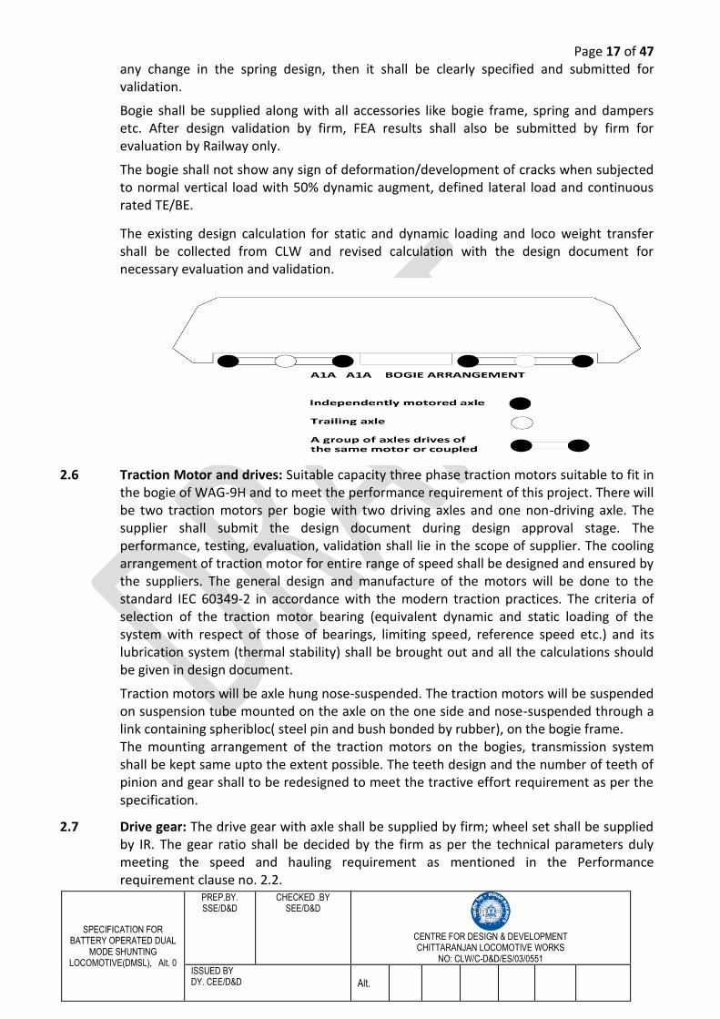
There will be A1A - A1A bogie arrangement (shown below) with two traction motor per bogie and one non-driving axle without motor as it will lead to cost saving in terms of motor and gear and pinion with easier design and also provides the opportunity to use high rated traction motor. At this stage no modification in the bogie is envisaged, however firm should study the bogie and suspension system of WAG-9H in detail. The contractor shall study the bogie and suspension system of the WAG-9H platform in detail for accommodating the newly designed traction motors and drive gear. In case of requirement of any minor modifications in the existing bogie and suspension system, the contractor shall submit the detailed drawings and 3D models during design approval stage for evaluation and validation of the design. The responsibility of modification in the bogie for fitment of the drive gear, traction motor and its performance, validation, evaluation and safe operation in the DMSL shall completely lie with the supplier. The suggested modifications will be carried out by supplier after approval of CLW.
Firm shall examine the existing calculation for determining the spring characteristics and damping values and submit the revised calculation with the design document. If there is
Page 17 of 47
SPECIFICATION FOR BATTERY OPERATED DUAL
MODE SHUNTING LOCOMOTIVE(DMSL), Alt. 0
PREP.BY. SSE/D&D
CHECKED .BY SEE/D&D
CENTRE FOR DESIGN & DEVELOPMENT CHITTARANJAN LOCOMOTIVE WORKS
NO: CLW/C-D&D/ES/03/0551
ISSUED BY DY. CEE/D&D Alt.
any change in the spring design, then it shall be clearly specified and submitted for validation.
Bogie shall be supplied along with all accessories like bogie frame, spring and dampers etc. After design validation by firm, FEA results shall also be submitted by firm for evaluation by Railway only.
The bogie shall not show any sign of deformation/development of cracks when subjected to normal vertical load with 50% dynamic augment, defined lateral load and continuous rated TE/BE.
The existing design calculation for static and dynamic loading and loco weight transfer shall be collected from CLW and revised calculation with the design document for necessary evaluation and validation.
2.6 Traction Motor and drives: Suitable capacity three phase traction motors suitable to fit in the bogie of WAG-9H and to meet the performance requirement of this project. There will be two traction motors per bogie with two driving axles and one non-driving axle. The supplier shall submit the design document during design approval stage. The performance, testing, evaluation, validation shall lie in the scope of supplier. The cooling arrangement of traction motor for entire range of speed shall be designed and ensured by the suppliers. The general design and manufacture of the motors will be done to the standard IEC 60349-2 in accordance with the modern traction practices. The criteria of selection of the traction motor bearing (equivalent dynamic and static loading of the system with respect of those of bearings, limiting speed, reference speed etc.) and its lubrication system (thermal stability) shall be brought out and all the calculations should be given in design document.
Traction motors will be axle hung nose-suspended. The traction motors will be suspended on suspension tube mounted on the axle on the one side and nose-suspended through a link containing spheribloc( steel pin and bush bonded by rubber), on the bogie frame. The mounting arrangement of the traction motors on the bogies, transmission system shall be kept same upto the extent possible. The teeth design and the number of teeth of pinion and gear shall to be redesigned to meet the tractive effort requirement as per the specification.
2.7 Drive gear: The drive gear with axle shall be supplied by firm; wheel set shall be supplied by IR. The gear ratio shall be decided by the firm as per the technical parameters duly meeting the speed and hauling requirement as mentioned in the Performance requirement clause no. 2.2.
Page 18 of 47
SPECIFICATION FOR BATTERY OPERATED DUAL
MODE SHUNTING LOCOMOTIVE(DMSL), Alt. 0
PREP.BY. SSE/D&D
CHECKED .BY SEE/D&D
CENTRE FOR DESIGN & DEVELOPMENT CHITTARANJAN LOCOMOTIVE WORKS
NO: CLW/C-D&D/ES/03/0551
ISSUED BY DY. CEE/D&D Alt.
2.8 Brake system: The existing brake system(E-70/CCB brake system) of WAG-9HC system shall be retained and used.
2.9 Pneumatic system: The existing pneumatic system of WAG-9H locomotive should be retained as it is. The supplier shall submit the mechanical and electrical connection during design approval stage.
2.10 Auxiliary Loads: The auxiliary system shall consist of auxiliary machines, Blowers-motors, compressors motors, oils/water pumps, battery charger, DC loads and associated protection system. The AC auxiliary system shall be galvanically isolated from the traction power system and the DC battery system. Auxiliary system design shall ensure that there is no surge/spike in the output voltage (vector sum of three phases) with respect to earth shall be as low as possible, preferably zero. The rating of auxiliary loads shall depend upon the design. Further firm can use the existing auxiliary loads as used in existing WAG-9H locomotive. But the proposed total auxiliary load in battery mode operation may vary from the existing auxiliary load of WAG-9H locomotive, as required auxiliary load in battery mode are Traction Motor Blowers, Water pump converters, Scavenge Blowers, Compressors and Battery chargers. The footprint of the auxiliary machines should be kept same as in existing WAG-9H locomotive upto the extent possible.
Further it may require modification in the ratings of auxiliary machines like traction motor blower, oil cooling unit, hence firm should mention the above aspect in the offer for better evaluation. The details may however be worked out in the detailed design stage and submitted to CLW along with the proposal.
2.11 Transformer: The traction transformer needs to be duly meeting the requirements with latest technical knowhow and practices being adopted worldwide for traction applications. Firm manufacturer should consider the all aspects specified in the specification while designing the transformer and should take necessary approval during design stage.
The kVA rating of the transformer shall be depend upon the design and shall be specified at a line voltage of 22.5kV and shall be designed to deliver a total current corresponding to the continuous rated traction motor currents at full voltage in OHE mode. The transformer windings shall also be designed to deliver the rated power at the maximum continuous line voltage of 30kV and it may contain a separate winding for battery charger or not in case of battery charging via dc link of the integrated converter. Further the traction windings shall be designed with appropriate resistance, inductance value in such a way that it can able to deliver maximum power requirement as per specification.
The transformer shall be oil immersed and forced oil cooled by means of an oil-circulating pump and a radiator. Further the footprint and cooling arrangement of the transformer should be kept same as in existing WAG-9H locomotive i.e. LOT 7500 transformer.
The existing cooling system of WAG-9H locomotive is to be utilized for cooling circuit of the transformer. Maximum temperature of the winding and the oil conform to IEC-60310 minus 20˚C.
The firm shall study the rating of existing radiator for its efficacy to meet the cooling requirements envisaged against the specification. In case there is a need to redesign the radiator, the following aspects shall be considered:
Page 19 of 47
SPECIFICATION FOR BATTERY OPERATED DUAL
MODE SHUNTING LOCOMOTIVE(DMSL), Alt. 0
PREP.BY. SSE/D&D
CHECKED .BY SEE/D&D
CENTRE FOR DESIGN & DEVELOPMENT CHITTARANJAN LOCOMOTIVE WORKS
NO: CLW/C-D&D/ES/03/0551
ISSUED BY DY. CEE/D&D Alt.
a. The radiator shall be in two separate parts for power converter and transformer.
b. The power converter shall be water cooled and transformer shall be oil cooled. c. The radiator shall be air blast cooled by means of motor driven blower set. d. The radiator shall be so designed that cleaning interval is synchronized with the
scheduled maintenance, but shall not be less than 6 months.
Oil cooling blower units are used to provide necessary cooling to the heat exchanger. Firm may propose a better and more efficient cooling system other than used in WAG-9H locomotive, but in this case the design validation will be required during design approval stage.
2.12 Traction related details
2.12.1 The nominal overhead voltage is 25kV AC 50Hz, single phase. The supply voltage is fed to the traction transformer through a Vacuum Circuit Breaker (VCB). The transformer output is to be connected to the power converter. The overhead traction supply is subjected to variations as under:
Nominal Voltage -25kV AC Maximum Voltage -30kV AC Minimum Voltage -19kV AC Occasional Maximum Voltage -31kV AC Occasional Minimum Voltage -16.5Kv AC Supply Frequency -50Hz±3%
The occasional maximum and occasional minimum voltage may persist for 30 minutes.
Pantograph bouncing upto 45ms (limit of zero pressure contact) normally experienced in service shall not adversely affect the performance of Integrated Converter and its output.
2.12.2 Integrated converter: Suitably designed integrated converter shall be used and the traction battery should be integrated in the DC link of the power converter. Firm shall propose an integrated converter consisting of traction converter and auxiliary converter with common DC link and housed in the same space envelope available on the locomotive. Further the footprint should be kept same as in the WAG-9H locomotive for traction converter upto the maximum possible extent.
Both integrated converter shall be identical in all aspects. In such a case, auxiliary converter shall be capable of supplying the complete load of the auxiliaries at rated frequency including battery charger for locomotive battery. In case of isolation of one of the auxiliary converter the other converter shall take the complete auxiliary load including battery charging and the changeover arrangement shall be automatic. Firm shall propose discussed during design stage prior to manufacturing of prototype unit. In order to reduce energy consumption as well as to increase equipment life, multiple level ventilation control shall be adopted, which shall vary the output of all the blowers according to the cooling needs. Auxiliary converter output and control system shall be designed accordingly considering the total harmonic distortion at output voltage shall be less than 10% and supply regulated to ±5% of the nominal voltage under all operating condition.
With the availability of IGBTs with higher switching frequency, firm may propose elimination of existing harmonic filter, thereby, eliminating the need of filter winding in the traction transformer, resistor and capacitor in the circuit. Firm should mention the
Page 20 of 47
SPECIFICATION FOR BATTERY OPERATED DUAL
MODE SHUNTING LOCOMOTIVE(DMSL), Alt. 0
PREP.BY. SSE/D&D
CHECKED .BY SEE/D&D
CENTRE FOR DESIGN & DEVELOPMENT CHITTARANJAN LOCOMOTIVE WORKS
NO: CLW/C-D&D/ES/03/0551
ISSUED BY DY. CEE/D&D Alt.
above aspect in the offer for better evaluation. The details may however be worked out in the detailed design stage. Further the efficiency of the Propulsion system, consisting of transformer, power converter (line side converter and drive side converter) and traction motor shall not be less than 87% at full load. Efficiency at full load means, efficiency computed from parameters measured at conditions corresponding to full load and governed by IEC 60310 for transformer, IEC-61287-1 for converters, IEC60349-2 for traction motors.
The following aspects should be considered while designing the integrated converter:
a. Fault of any converter module (traction converter/auxiliary converter) inside the integrated converter shouldn’t affect the performance of remaining converters of the integrated converter.
b. The designed integrated converter may need extra space and footprint may also need to be changed. In such case, firm should study the existing layout of the machine room and suggest the changes to CLW during detailed design stage. It is preferable that the weight of IGBT based Integrated Converter shall not exceed 3300/4000kg. However, under any circumstances arising out of tentative changes in the machine room layout, the centre of gravity (CG) of the locomotive should not be altered.
c. Firm should modify the cable index related to integrated converter shall lie on the firm and same should be provided to CLW at the time of approval of design document.
d. There shall be axle controlled inverter for each traction motor.
e. Suitable redundancy in the vital PCBs connected with safety and power supplies, so that the locomotive failure and degradation in performance is minimized in the event of the failure.
f. The battery charger of the traction battery and loco battery both should be supplied from the auxiliary converter supply. As the single auxiliary converter of one Integrated Converter shall be sufficient for total auxiliary load and in case of failure the total load shall be shifted to another auxiliary converter of other Integrated Converter. Hence it leads to redundancy of the battery chargers.
2.12.3 Control Electronics: The central electronics should be TCN based VCU and have following features :
a. Control and communication shall be as per IEC 61375 and UIC 556. The programmable devices shall be programmed using language compliant to IEC 61131.
b. The control algorithm and downloadable code with diagnostic uploading/downloading tool shall be provided to IR. In addition to this the working principle, safety and control logic should be in line the existing MICAS based locomotive for which necessary document maybe collected IR.
c. As there would be frequent cab changing required due to shunting operation. Hence self-hold mode function is imperative.
d. All functions of the locomotive are controlled by central electronics. It shall be in the form of bus stations with the processors. The bus stations communicate with each other via fiber optic cables which are resistant to the effects of
Page 21 of 47
SPECIFICATION FOR BATTERY OPERATED DUAL
MODE SHUNTING LOCOMOTIVE(DMSL), Alt. 0
PREP.BY. SSE/D&D
CHECKED .BY SEE/D&D
CENTRE FOR DESIGN & DEVELOPMENT CHITTARANJAN LOCOMOTIVE WORKS
NO: CLW/C-D&D/ES/03/0551
ISSUED BY DY. CEE/D&D Alt.
electromagnetic interference (EMI). However in place of OFC other physical mediums like MVB-ESD, MVB-EMD and Ethernet can also be utilized. But there should be hot redundancy and the insulation & EMI should be with proper differentials.
e. VCU set shall be fully redundant and there shall be concept of Master and Slave for which master is to be considered for VCU-1 and slave as VCU-2. In case of failure, the master shall shift to slave only with one acknowledgement with the help of BPFA (Push Button for fault acknowledgement) switch installed on Driver console.
f. Firm shall also provide proper tools and application software for viewing, editing, downloading, uploading, etc of the program/code into the upgraded locomotive.
g. The control system shall integrate the task of fault diagnostics and display the same in addition to its control task. It shall be capable of monitoring the status of all the vital equipment continuously on real time basis. It shall also take appropriate protective action and shut down of the equipment whenever necessary.
h. Features of self-check and calibration shall be incorporated in the design.
i. The VCU shall have a diagnostics computer, with non-volatile memory, to store all the relevant diagnostic data. On occurrence of each fault, besides the fault information regarding equipment parameters, background data with time stamp shall also be capture pos-trigger and pre-trigger background information. The fault display to driver shall also accompany the standard trouble shooting instructions in simple language. The diagnostic computer shall specify diagnostic of fault up to card level. The diagnostic system shall be able to identify and log the faults of the locomotive on account of wrong operation by the driver and such data shall be stored in the diagnostic computer for a period of not less than 100 days. Application software shall be provided to facilitate the fault diagnosis and the analysis of equipment failures. The steps required for investigation shall be displayed in simple language along with background information. Such software shall be compatible for working on commercially available on current operating system.
j. The diagnostic equipment comprises a diagnosis computer with monitor and keyboard in the drivers cab. This provides an effective support for the duties of the locomotive driver and maintenance personnel.
k. It shall be possible to access all the processors of the propulsion equipment within a locomotive using a standard laptop connected/interfaced to one standard port available on the VCU. Such access is needed for uploading of firmware/application program, visualization of process parameters and also force or record the same and downloading the diagnostic data. Required interfaces shall be built in the VCU so that standard laptops, with commercially available operating systems can be directly plugged to the VCU without any special interface. A suitable software tool shall also be provided in the laptops. Using this tool, it shall be possible to reset the diagnostic memory for further recording. This tool shall also provide details of line analysis facility.
l. The electronics shall be seen from the remaining part of the machine room so as to ensure that there is no ingress whatsoever into the electronics. For its cooling,
Page 22 of 47
SPECIFICATION FOR BATTERY OPERATED DUAL
MODE SHUNTING LOCOMOTIVE(DMSL), Alt. 0
PREP.BY. SSE/D&D
CHECKED .BY SEE/D&D
CENTRE FOR DESIGN & DEVELOPMENT CHITTARANJAN LOCOMOTIVE WORKS
NO: CLW/C-D&D/ES/03/0551
ISSUED BY DY. CEE/D&D Alt.
internal ventilation arrangement along with efficient heat exchanger for removal of heat shall be provided. The electronics shall be designed with adequate margin so that there are no failures on the thermal account.
m. The majority of control and monitoring function shall be implemented by the software so as to reduce hardware and cables.
n. It shall be possible to execute parametric changes in the software in respect of user interface viz. modifying some of the permissible parameters for adjusting the characteristic within permissible range, adding/ altering the protection features, if so required in future, in order to improve the operation of the locomotive. The firm shall provide all necessary equipment and accessories required for the purpose.
o. In case the control unit architecture is rack based then the electronic cards and coupler/connectors shall be polarized or suitably designed with necessary locking arrangement to ensure that insertion in wrong position is not possible.
p. Capacitors shall be suitably rated, keeping in view the high ambient temperature specified, vibrations of electric rolling stock and electrical surges expected during operation. High failure rates of electrolytes capacitors mounted on PCBs of electronic cards are expected due to high operating temperature/voltage/current vis-à-vis designed operating temperature/voltage /current. Dry type capacitors shall only be used. Expected life of cards, and electronics in general shall be at least 18 years under working condition.
q. It shall be possible to operate the locomotive in multiple with other locomotive of the same type. It shall be possible to operate upto 3 locomotive in multiple operation as per IEC-61375.
2.12.4 The system and equipments shall be of proven latest technology specially adopted for application to meet the performance requirements under environmental conditions specified in Chapter 3. Adequate margin shall be built in the design, particularly to take care of condition of high ambient temperatures, dusty condition, high humidity prevailing in India.
2.12.5 In design and construction, reliability and maintainability shall be of paramount consideration. Supplier shall submit reliability calculations indicating MTBF for different devices, cards and sub-assemblies. Adequate margin shall be provided to take into account ambient conditions prevailing in India. The components shall be sourced from reputed firms.
2.12.6 High efficiency of equipment shall be important consideration, next only to high reliability. The components and technology used shall ensure very high efficiency of the converter. Supplier shall furnish the expected efficiency with respect to vehicle load/speed with necessary calculations. The efficiency of the Propulsion system, consisting of transformer, power converter (line side converter and drive side converter) and traction motor shall not be less than 87% at full load.
2.12.7 The design calculations of worst case temperature rise of equipment shall be made.
2.12.8 Dimension: Should be within the limit of MMD. These details shall be collected from Indian Railway. Annexure-V may be referred for MMD related information of BG electric locomotive.
Page 23 of 47
SPECIFICATION FOR BATTERY OPERATED DUAL
MODE SHUNTING LOCOMOTIVE(DMSL), Alt. 0
PREP.BY. SSE/D&D
CHECKED .BY SEE/D&D
CENTRE FOR DESIGN & DEVELOPMENT CHITTARANJAN LOCOMOTIVE WORKS
NO: CLW/C-D&D/ES/03/0551
ISSUED BY DY. CEE/D&D Alt.
2.12.9 The additional equipments including battery set will be located in such a way so that the DMSL remains balanced weight wise and the Centre of gravity (CG) remains as before addition of battery mode equipments.
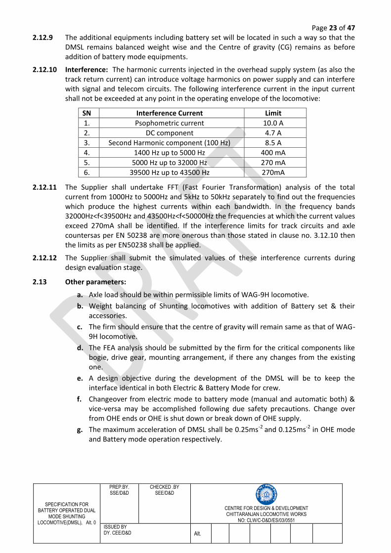
2.12.10 Interference: The harmonic currents injected in the overhead supply system (as also the track return current) can introduce voltage harmonics on power supply and can interfere with signal and telecom circuits. The following interference current in the input current shall not be exceeded at any point in the operating envelope of the locomotive:
SN Interference Current Limit
1. Psophometric current 10.0 A 2. DC component 4.7 A 3. Second Harmonic component (100 Hz) 8.5 A 4. 1400 Hz up to 5000 Hz 400 mA
5. 5000 Hz up to 32000 Hz 270 mA 6. 39500 Hz up to 43500 Hz 270mA
2.12.11 The Supplier shall undertake FFT (Fast Fourier Transformation) analysis of the total current from 1000Hz to 5000Hz and 5kHz to 50kHz separately to find out the frequencies which produce the highest currents within each bandwidth. In the frequency bands 32000Hz<f<39500Hz and 43500Hz<f<50000Hz the frequencies at which the current values exceed 270mA shall be identified. If the interference limits for track circuits and axle countersas per EN 50238 are more onerous than those stated in clause no. 3.12.10 then the limits as per EN50238 shall be applied.
2.12.12 The Supplier shall submit the simulated values of these interference currents during design evaluation stage.
2.13 Other parameters:
a. Axle load should be within permissible limits of WAG-9H locomotive.
b. Weight balancing of Shunting locomotives with addition of Battery set & their accessories.
c. The firm should ensure that the centre of gravity will remain same as that of WAG-9H locomotive.
d. The FEA analysis should be submitted by the firm for the critical components like bogie, drive gear, mounting arrangement, if there any changes from the existing one.
e. A design objective during the development of the DMSL will be to keep the interface identical in both Electric & Battery Mode for crew.
f. Changeover from electric mode to battery mode (manual and automatic both) & vice-versa may be accomplished following due safety precautions. Change over from OHE ends or OHE is shut down or break down of OHE supply.
g. The maximum acceleration of DMSL shall be 0.25ms-2 and 0.125ms-2 in OHE mode and Battery mode operation respectively.
Page 24 of 47
SPECIFICATION FOR BATTERY OPERATED DUAL
MODE SHUNTING LOCOMOTIVE(DMSL), Alt. 0
PREP.BY. SSE/D&D
CHECKED .BY SEE/D&D
CENTRE FOR DESIGN & DEVELOPMENT CHITTARANJAN LOCOMOTIVE WORKS
NO: CLW/C-D&D/ES/03/0551
ISSUED BY DY. CEE/D&D Alt.
CHAPTER – 3: OPERTAING AND ENVIRONMENTAL CONDITIONS
3.0 Climatic and Environmental Condition: The climatic and environmental conditions
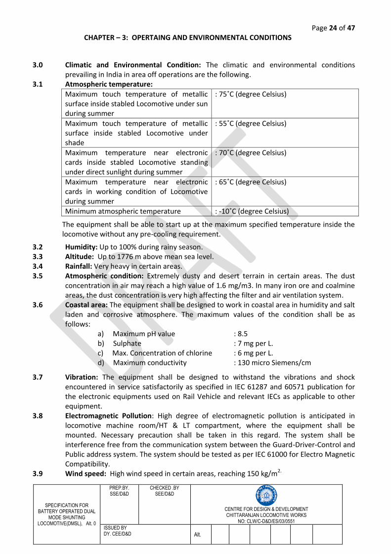
prevailing in India in area off operations are the following. 3.1 Atmospheric temperature:
Maximum touch temperature of metallic surface inside stabled Locomotive under sun during summer
: 75˚C (degree Celsius)
Maximum touch temperature of metallic surface inside stabled Locomotive under shade
: 55˚C (degree Celsius)
Maximum temperature near electronic cards inside stabled Locomotive standing under direct sunlight during summer
: 70˚C (degree Celsius)
Maximum temperature near electronic cards in working condition of Locomotive during summer
: 65˚C (degree Celsius)
Minimum atmospheric temperature : -10˚C (degree Celsius)
The equipment shall be able to start up at the maximum specified temperature inside the locomotive without any pre-cooling requirement.
3.2 Humidity: Up to 100% during rainy season. 3.3 Altitude: Up to 1776 m above mean sea level. 3.4 Rainfall: Very heavy in certain areas. 3.5 Atmospheric condition: Extremely dusty and desert terrain in certain areas. The dust
concentration in air may reach a high value of 1.6 mg/m3. In many iron ore and coalmine areas, the dust concentration is very high affecting the filter and air ventilation system.
3.6 Coastal area: The equipment shall be designed to work in coastal area in humidity and salt laden and corrosive atmosphere. The maximum values of the condition shall be as follows:
a) Maximum pH value : 8.5 b) Sulphate : 7 mg per L. c) Max. Concentration of chlorine : 6 mg per L. d) Maximum conductivity : 130 micro Siemens/cm
3.7 Vibration: The equipment shall be designed to withstand the vibrations and shock encountered in service satisfactorily as specified in IEC 61287 and 60571 publication for the electronic equipments used on Rail Vehicle and relevant IECs as applicable to other equipment.
3.8 Electromagnetic Pollution: High degree of electromagnetic pollution is anticipated in locomotive machine room/HT & LT compartment, where the equipment shall be mounted. Necessary precaution shall be taken in this regard. The system shall be interference free from the communication system between the Guard-Driver-Control and Public address system. The system should be tested as per IEC 61000 for Electro Magnetic Compatibility.
3.9 Wind speed: High wind speed in certain areas, reaching 150 kg/m2.
Page 25 of 47
SPECIFICATION FOR BATTERY OPERATED DUAL
MODE SHUNTING LOCOMOTIVE(DMSL), Alt. 0
PREP.BY. SSE/D&D
CHECKED .BY SEE/D&D
CENTRE FOR DESIGN & DEVELOPMENT CHITTARANJAN LOCOMOTIVE WORKS
NO: CLW/C-D&D/ES/03/0551
ISSUED BY DY. CEE/D&D Alt.
3.10 Solar radiation: The locomotive shall be exposed to solar radiation and the design of the integrated converter shall take this into consideration. A minimum value of 1kW/m2 shall be applied during summers.
3.11 EMC 3.11.1 The additional equipments of DMSL shall comply with the EN50121/IEC62236 series of
railway electromagnetic compatibility standards and EN50238 3.11.2 The supplier shall prepare, implement and maintain and EMC management plan in
accordance with the standards referenced in clause 2.2.1 of this specifications and standards.
3.12 Train and Locomotive Resistance Data 3.12.1 Train and Locomotive Resistance Data: The train resistance and locomotive resistance
data as followed by IR is as follows: 3.12.2 General: It is important to note that this data pertains to the existing system and for the
existing generation of locomotives and rolling stock for speeds up to 120 kmph 3.12.3 Train resistance (of BOXN wagon excluding locomotive)
(i) Mean starting resistance on level tangent track (including acceleration reserve):
5.0 kg/tone
(ii) Mean running resistance on level tangent track (excluding locomotive up to 120 kmph):
Rf = 0.6855 + 0.02112 V + 0.000082 V2 (kg/tonne) Rf = the resistance in kg per metric tonne of freight train V= The speed in kmph
(iii) Grade resistance
= 1/G x 1000 (in kg/tonne), where G is gradient (e.g. G=200 in case of 1 in 200 gradient)
(iv) Curvature resistance = 0.4 x curvature in degree (in kg/tonne)
3.12.4 Loco resistance as followed by IR is
(i) Starting resistance on level tangent track:
6 kg/tone
(ii) Running resistance on level tangent track:
RL = 0.647+ 13.17/W + 0.00933 V + 0.057V2 /WN [kg/tonne] RL = Resistance in kg/tonne of locomotive N = Number of axles W = Axle load of the loco in tonne V = speed in kmph
Page 26 of 47
SPECIFICATION FOR BATTERY OPERATED DUAL
MODE SHUNTING LOCOMOTIVE(DMSL), Alt. 0
PREP.BY. SSE/D&D
CHECKED .BY SEE/D&D
CENTRE FOR DESIGN & DEVELOPMENT CHITTARANJAN LOCOMOTIVE WORKS
NO: CLW/C-D&D/ES/03/0551
ISSUED BY DY. CEE/D&D Alt.
CHAPTER – 4: SCOPE OF WORK/SUPPLY
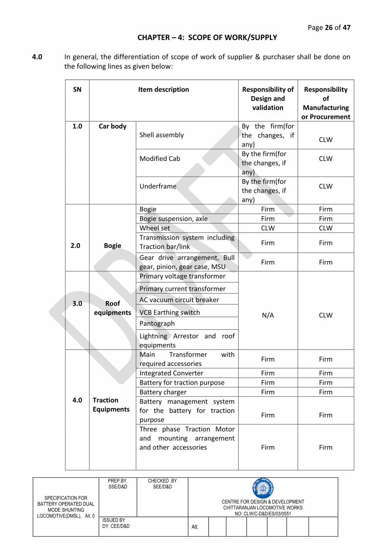
4.0 In general, the differentiation of scope of work of supplier & purchaser shall be done on the following lines as given below:
SN
Item description
Responsibility of Design and validation
Responsibility of
Manufacturing or Procurement
1.0 Car body Shell assembly
By the firm(for the changes, if any)
CLW
Modified Cab By the firm(for the changes, if any)
CLW
Underframe By the firm(for the changes, if any)
CLW
2.0
Bogie
Bogie Firm Firm
Bogie suspension, axle Firm Firm
Wheel set CLW CLW
Transmission system including Traction bar/link
Firm Firm
Gear drive arrangement, Bull gear, pinion, gear case, MSU
Firm Firm
3.0
Roof equipments
Primary voltage transformer
N/A
CLW
Primary current transformer
AC vacuum circuit breaker
VCB Earthing switch
Pantograph
Lightning Arrestor and roof equipments
4.0
Traction Equipments
Main Transformer with required accessories
Firm Firm
Integrated Converter Firm Firm
Battery for traction purpose Firm Firm
Battery charger Firm Firm
Battery management system for the battery for traction purpose
Firm
Firm
Three phase Traction Motor and mounting arrangement and other accessories
Firm Firm
Page 27 of 47
SPECIFICATION FOR BATTERY OPERATED DUAL
MODE SHUNTING LOCOMOTIVE(DMSL), Alt. 0
PREP.BY. SSE/D&D
CHECKED .BY SEE/D&D
CENTRE FOR DESIGN & DEVELOPMENT CHITTARANJAN LOCOMOTIVE WORKS
NO: CLW/C-D&D/ES/03/0551
ISSUED BY DY. CEE/D&D Alt.
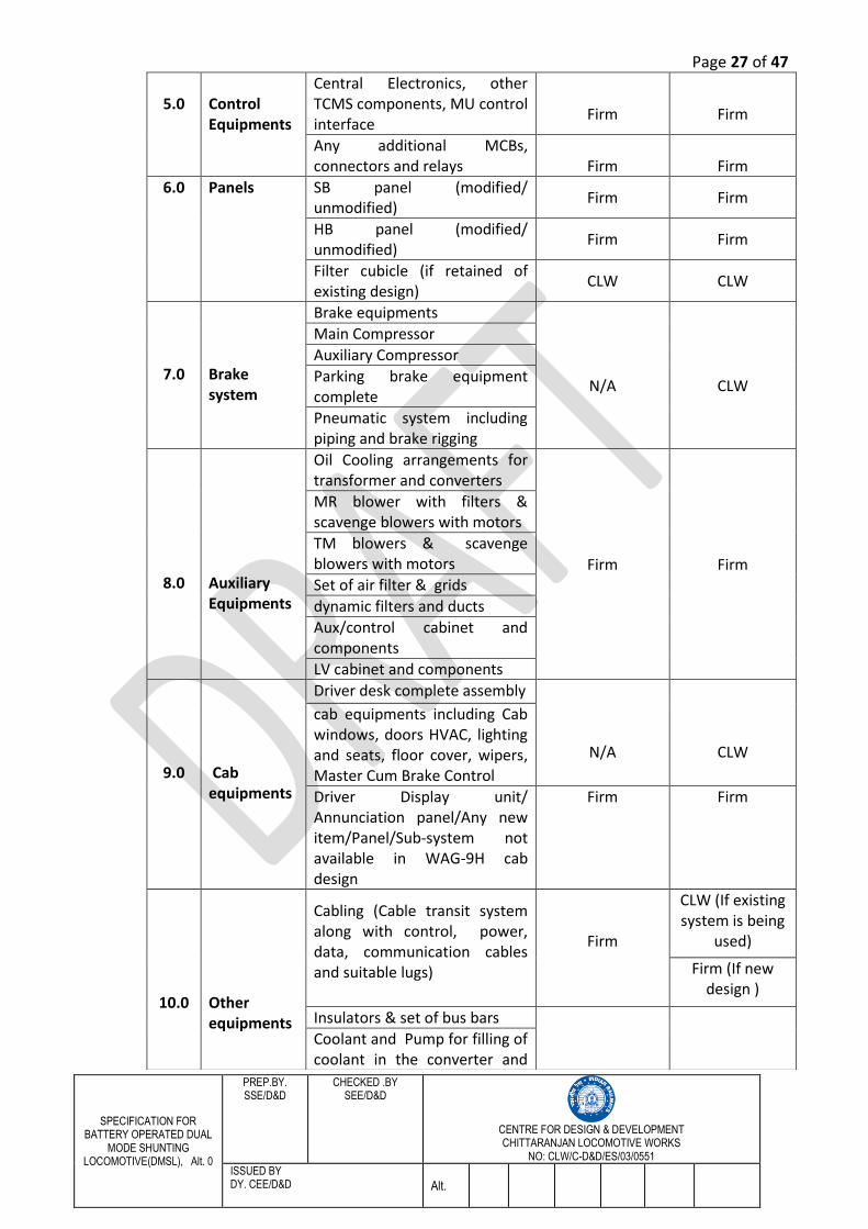
5.0
Control Equipments
Central Electronics, other TCMS components, MU control interface
Firm
Firm
Any additional MCBs, connectors and relays
Firm
Firm
6.0 Panels SB panel (modified/ unmodified)
Firm Firm
HB panel (modified/ unmodified)
Firm Firm
Filter cubicle (if retained of existing design)
CLW CLW
7.0
Brake system
Brake equipments
N/A
CLW
Main Compressor
Auxiliary Compressor
Parking brake equipment complete
Pneumatic system including piping and brake rigging
8.0
Auxiliary Equipments
Oil Cooling arrangements for transformer and converters
Firm Firm
MR blower with filters & scavenge blowers with motors
TM blowers & scavenge blowers with motors
Set of air filter & grids
dynamic filters and ducts
Aux/control cabinet and components
LV cabinet and components
9.0
Cab equipments
Driver desk complete assembly
N/A
CLW
cab equipments including Cab windows, doors HVAC, lighting and seats, floor cover, wipers, Master Cum Brake Control
Driver Display unit/ Annunciation panel/Any new item/Panel/Sub-system not available in WAG-9H cab design
Firm Firm
10.0
Other equipments
Cabling (Cable transit system along with control, power, data, communication cables and suitable lugs)
Firm
CLW (If existing system is being
used)
Firm (If new design )
Insulators & set of bus bars
Coolant and Pump for filling of coolant in the converter and
Page 28 of 47
SPECIFICATION FOR BATTERY OPERATED DUAL
MODE SHUNTING LOCOMOTIVE(DMSL), Alt. 0
PREP.BY. SSE/D&D
CHECKED .BY SEE/D&D
CENTRE FOR DESIGN & DEVELOPMENT CHITTARANJAN LOCOMOTIVE WORKS
NO: CLW/C-D&D/ES/03/0551
ISSUED BY DY. CEE/D&D Alt.
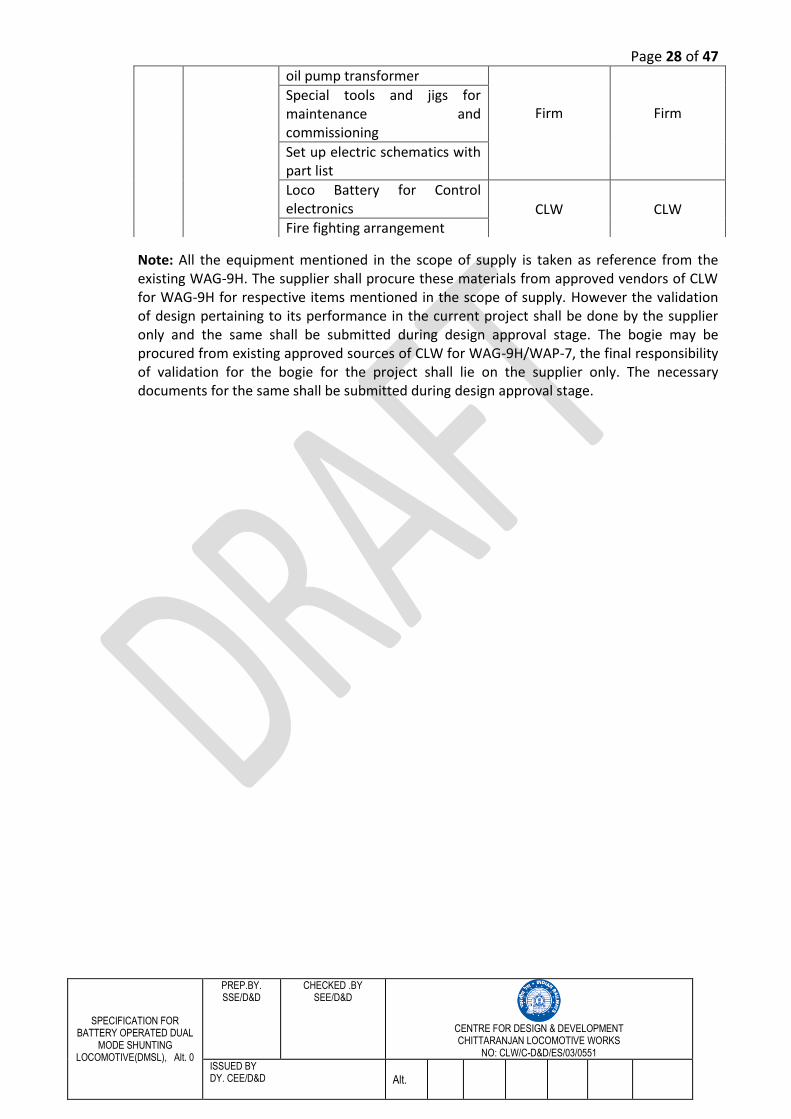
Note: All the equipment mentioned in the scope of supply is taken as reference from the existing WAG-9H. The supplier shall procure these materials from approved vendors of CLW for WAG-9H for respective items mentioned in the scope of supply. However the validation of design pertaining to its performance in the current project shall be done by the supplier only and the same shall be submitted during design approval stage. The bogie may be procured from existing approved sources of CLW for WAG-9H/WAP-7, the final responsibility of validation for the bogie for the project shall lie on the supplier only. The necessary documents for the same shall be submitted during design approval stage.
oil pump transformer
Firm
Firm Special tools and jigs for maintenance and commissioning
Set up electric schematics with part list
Loco Battery for Control electronics CLW
CLW
Fire fighting arrangement
Page 29 of 47
SPECIFICATION FOR BATTERY OPERATED DUAL
MODE SHUNTING LOCOMOTIVE(DMSL), Alt. 0
PREP.BY. SSE/D&D
CHECKED .BY SEE/D&D
CENTRE FOR DESIGN & DEVELOPMENT CHITTARANJAN LOCOMOTIVE WORKS
NO: CLW/C-D&D/ES/03/0551
ISSUED BY DY. CEE/D&D Alt.
CHAPTER – 5: GENERAL CONDITIONS, INSPECTIONS, TEST & TRIALS AND OTHER REQUIREMENTS
5.0 General Conditions 5.1 General design features of Shunting locomotive 5.1.1 (i) The equipments shall incorporate features to yield low maintenance requirements,
easy maintainability, high reliability in operation and high efficiency as compared to diesel shunting locomotives.
(ii) The contractor will provide the items required for proper functioning of the locomotive in accordance with current international practices.
(iii)The specification has been prepared for the general guidance of the contractor to prepare the key design for the proposed locomotives. Any deviation from specification, intended to improve the performance, utility and efficiency of the locomotive as a whole or part thereof may be proposed for consideration. All such proposals will, however be accompanied with complete technical details and justification for proposed deviation.
5.1.2 Approval of design: The design of the equipments of DMSL shall be developed based on the requirements given in this specification and sound engineering practices. The design shall be developed in SI units.
5.1.3 The entire design of equipments for DMSL being supplied by the contractor to achieve the functionalities mentioned in the specification shall be carried out by the supplier and submitted to IR along with required technical data and calculations for necessary approval. The supplier shall be responsible for achieving the desired performance parameters of the locomotive for the equipment supplied by him. The manufacturing shall commence after the approval of design by IR.
5.1.4 The supplier shall submit all necessary data, designs, calculations, drawings and specifications referred in their drawings or design documents in English language as required by IR for examination and shall provide explanation and clarification of the documents for which approval is sought. The supplier shall depute his technical experts to IR for design discussions and finalisation. During the design approval stage, the supplier shall furnish complete set of specifications and standards as mentioned in the approved drawings & documents and shall also submit the list of equivalent Indian Standards, wherever applicable. Supplier shall submit complete design details, block diagrams, functional description of all sub-systems, schematic drawings, loading calculations, circuits, component rating, wiring diagrams, ventilation design, device rating & data sheets of converter, inverter and other power, control and the major equipment, loading of electronic equipment/components calculated under the ambient conditions as specified etc. The aspects covered above are not exhaustive and the supplier shall commit to supply/furnish complete technical details with respect to their system and equipment design and to the satisfaction of IR for design approval.
5.1.5 Supplier shall enclose details of their system design, weight particulars and it disposition covering all items basic software specification, electronics, communication protocols, display systems and any other aspect/equipment which is within the scope of supply of the supplier. The supplier shall also submit in their offer the simulated values of the maximum interference currents in the power supply.
Page 30 of 47
SPECIFICATION FOR BATTERY OPERATED DUAL
MODE SHUNTING LOCOMOTIVE(DMSL), Alt. 0
PREP.BY. SSE/D&D
CHECKED .BY SEE/D&D
CENTRE FOR DESIGN & DEVELOPMENT CHITTARANJAN LOCOMOTIVE WORKS
NO: CLW/C-D&D/ES/03/0551
ISSUED BY DY. CEE/D&D Alt.
5.1.6 The supplier shall submit the complete material/technical specification and sources of the components during design approval. The specification shall specifically be indicated on relevant drawings/documents.
5.1.7 The supplier shall furnish details of its Quality Assurance and Quality Control at the design approval stage. The quality checks to be made at various stages of manufacture, final assembly and commissioning with tolerance would be indicated. The system would also cover the quality assurance for brought out items.
5.1.8 Approval of design means the approval of general design features. For this purpose detailed drawings will be submitted to IR for approval before commencing manufacture. Notwithstanding approval from IR the supplier shall be wholly and completely responsible for the satisfactory performance of the equipment.
5.1.9 The supplier shall be responsible for carrying out the improvements and modifications at his own expense on all the equipment supplied, provided such modifications/improvements are decided to be necessary for meeting the requirements of reliability, performance, safety etc. jointly between supplier and purchaser.
5.1.10 For the purpose of technical decisions on improvements/modifications etc. on equipment, the final authority from purchaser’s side shall be IR. However, the decision on obsolescence management of component/module/assembly etc. shall be mutually agreed by IR and contractor.
5.1.11 The design will be made based on the requirements given in this specification and sound, proven and reliable engineering practices. The entire key design will be submitted with technical data and calculations for approval.
5.1.12 The contractor will submit a program indicating the expected dates on which drawings will be submitted for approval to IR to assist for planning resources for this approval.
5.1.13 The contractor’s engineer will deliver the drawings to IR and will provide explanation and clarification of the drawings for which approval is sought.
5.1.14 The design will be developed in SI units only. 5.1.15 Deviations proposed by the contractor in the interest of reliability and better performance
will be examined by IR in close consultation and association with the manufacturer so as to arrive at the final locomotive design.
5.1.16 All necessary data, design, calculations and drawings required by IR for examination of the manufacturer’s proposals will be furnished by the contractor.
5.1.17 The contractor will, in addition to furnishing information required by IR, also liaise with IR for any exposure of IR to current state of the art technology abroad so as to assess the relative merits/demerits of different designs offered and to arrive at mutually final designs. Information on experience on the equipment offered on different user railway systems will also be required by IR for an appropriate assessment. The manufacturer/contractor will give appropriate assistance in this regard also.
5.2 Inspection, test and trials: 5.2.1 The locomotive will be tested generally in accordance with IEC 61133(E.D.2.0): Rolling
stock- Testing of rolling stock on completion of construction and before entry into service. The inspection of the locomotive will be carried out by a representative of CLW.
5.2.2 The individual equipments, system and subsystems, as may be necessary shall be type and routine tested in accordance with relevant IEC, BS and CLW publications as per details given in clause 1.12 and the same should be approved by CLW, according to the test program to be drawn up by the contractor in consultation with CLW.
Page 31 of 47
SPECIFICATION FOR BATTERY OPERATED DUAL
MODE SHUNTING LOCOMOTIVE(DMSL), Alt. 0
PREP.BY. SSE/D&D
CHECKED .BY SEE/D&D
CENTRE FOR DESIGN & DEVELOPMENT CHITTARANJAN LOCOMOTIVE WORKS
NO: CLW/C-D&D/ES/03/0551
ISSUED BY DY. CEE/D&D Alt.
All equipment shall be routine tested according to the relevant IEC publications.
Wherever the relevant standard test procedures do not adequately cover the requirements of arduous environmental conditions prevailing in India, IR might lay down and ask for special tests apart from those specified that shall be required to be conducted. These may include accelerated ageing tests and endurance test.
Required type tests of electrical and mechanical equipments shall be carried out by the contractor at his own responsibility and costs and in the presence of and to the satisfaction of the Inspecting officials of CLW. The type test shall be carried out at the manufacturing premises of the contractor where all the facility required for type test shall made available by the contractor.
5.2.3 The Supplier shall formulate and submit type and routine test protocol/plan at design approval stage for approval of IR before undertaking manufacture. It shall, however, be open for IR to waive some of tests in case of equipment and subassemblies, where; the manufacturer can establish to the satisfaction of IR that such tests have already been carried out earlier on the same equipment and where equipment has been proved in prolonged service.
5.3 Bogie/Under frame/Body testing: In case the modifications are suggested in the bogie then following tests shall be carried out.
Bogie testing: The bogie frame shall be subjected to two times the normal duty load without any permanent distortion and to three times the normal duty load without any sign of cracking or failure.
The bogie frame will be subjected to dynamic load testing (10 million cycles) as per loading condition given below:
a. Normal vertical load ±50% dynamic augment for passenger locomotives.
b. Lateral load of 4T for locomotives.
c. Continuous rated tractive effort/braking effort.
The dynamic tests will be done for 10 million cycles without any signs of cracks or deformations. The measured stress values will remain within the endurance limit of the material used at all critical locations.
5.4 Equipment/System/Subsystems testing: 5.4.1 The equipment, systems and subsystems will be type/routine tested accordingly to this
specification and standards.
Whenever the relevant standard test procedure for type and routine tests prescribed in accordance with this specification and standards do not adequately cover the requirements; IR might lay down the details of special tests other than that will be required to be conducted at the contractor’s work. In such case the contractor will give a budgetary quotation for specific tests. The tests which will come under this category may include:
i. Effects of electrical stresses.
Page 32 of 47
SPECIFICATION FOR BATTERY OPERATED DUAL
MODE SHUNTING LOCOMOTIVE(DMSL), Alt. 0
PREP.BY. SSE/D&D
CHECKED .BY SEE/D&D
CENTRE FOR DESIGN & DEVELOPMENT CHITTARANJAN LOCOMOTIVE WORKS
NO: CLW/C-D&D/ES/03/0551
ISSUED BY DY. CEE/D&D Alt.
ii. Special type of endurance tests on contractors, relays, master controller and such other equipments which may impose mechanical operation and electrical loadings simultaneously for a large number of cycles of operation.
iii. Stress measurement and fatigue life estimation of parts subjected to alternating stresses, rotating parts like blower impellers, rotors etc.
iv. Special load simulation tests. v. Tests to establish satisfactory performance over the entire range of variable system
conditions like voltage, frequency, temperature, humidity etc.
It may be open for IR to waive some of these tests in the case of equipments/subassemblies where the manufacturer can establish to the satisfaction of IR that such tests have already been carried out earlier or where the equipments have been proven in prolonged service.
5.4.2 All the type and routine tests mentioned in the IEC 60349-2 including optional tests shall be conducted on the traction motor. Following additional special tests shall also be included if not done earlier:
5.4.3 Witness of test: Some of these tests may be required to be witnessed by the Inspecting
officer.
5.4.4 Raw material/component testing: IR may also in addition, require test results on raw materials and components of critical nature, so as to ensure that they meet the performance and reliability stipulations. This may extend to components/equipments/raw materials not manufactured in the contractor’s works, but purchased by him.
5.4.5 Furnishing of test results: The contractor shall be expected to furnish results of necessary tests and inspections carried out internally and in the presence of the Inspecting officials.
5.5 Oscillation tests: The DMSL locomotive shall be subjected to oscillation trials in India to prove the riding and stability performance of locomotive at the maximum tests speed as per the criteria indicated below on a track of standard specified in the table given below, which is to be confirmed before commencement of the trails, with new and minimum standard wheel tread profile to be agreed with IR.
i. Maximum lateral force (at axle box level): 4T ii. Maximum vertical dynamic augment: 30%
iii. Maximum derailment co-efficient: 1 iv. Lateral and vertical acceleration in the driving cab and at a point as close to the
bogie: <0.3g v. Maximum ride index in the driving cab at floor level: 3.75
No. of peaks of lateral and vertical acceleration exceeding 0.2g shall be kept to minimum.
Instrumentation and tests shall be carried out by IR and evaluation of the results shall be done by IR in consultation with the contractor.
Track condition:
a. Gauge Broad Gauge system of Indian Railway(1676mm)
b. Track structure The track shall be to a minimum standard of 52kg(90UTS) rails on sleeper to M+7 density and depth of ballast cushion below
Page 33 of 47
SPECIFICATION FOR BATTERY OPERATED DUAL
MODE SHUNTING LOCOMOTIVE(DMSL), Alt. 0
PREP.BY. SSE/D&D
CHECKED .BY SEE/D&D
CENTRE FOR DESIGN & DEVELOPMENT CHITTARANJAN LOCOMOTIVE WORKS
NO: CLW/C-D&D/ES/03/0551
ISSUED BY DY. CEE/D&D Alt.
sleepers of 250mm, which may consist of atleast 100mm clean ballast and the rest in caked up condition on compacted and stable formation or the track is to a minimum standard of 60kg/90 UTS rail laid on PSC sleepers density on 300mm ballast cushion below the sleepers which may consist of at least 150mm clean and the rest in caked up condition on compacted and stable formation and maintained to the standards to what has been recommended in RDSO’s report No. C&M-I, Vol.-I.
c. Schedule of dimensions:
Indian Railways Schedule of Dimensions for Board Gauge(1676mm), Rev.2004 with latest corrections and addendum slip.
d. Overall moving dimensions:
The locomotive with new wheels will be within the dimensions shown in RDSO Drg. No. ref. Annexure-V.
e. Sharpest curve and turnout to be negotiated:
175m radius(horizontal), 2500m radius (vertical). 6400mm overriding switch (curved) BG(1673mm) for 60kg (UIC).Vogel’s layout for negotiability, throw over at head stock and coupler movement with details of clearances will be submitted by contractor.
f. Clearance above the rail level:
No component will infringe a minimum clearance of 102mm above rail level with the locomotive fully loaded and wheels in fully worn condition.
g. Permissible track tolerances
BG Main lines
BG high speed routes (C&M1 Vol.1)
(i) Unevenness (3.6m base)
<15mm <6mm in general and <10mm at isolated spots
(ii) Twist (3.6mm base) 2.78mm/m <2.08mm/m
(iii) Gauge variation <±6mm <±6mm
(iv) Alignment/versine on 7.2m chord
<5mm <5mm in general with isolated 7mm on curves and 10mm on straight
Gauge widening on curves is provided as follows:
For curves radius more than 440m, the gauge variation will be from +15mm to -6mm.
For curves radius less than 440m, the gauge variation will be upto +20mm.
5.6 Other tests: The locomotive shall be subject to certain other tests conducted by IR with
contractor’s representative on IR track conditions mainly to satisfy the Railways regarding operational performance, capability and safety. The following tests may be conducted in this connection on one or more locomotives to satisfy IR regarding operation performance, capability and safety.
a. Dynamometer car tests to ascertain starting and rolling resistance of the locomotive and to prove tractive effort, speed characteristics and dynamic braking effort speed characteristics of the locomotive.
b. Adhesion tests to prove the adhesive capability of the locomotive.
Page 34 of 47
SPECIFICATION FOR BATTERY OPERATED DUAL
MODE SHUNTING LOCOMOTIVE(DMSL), Alt. 0
PREP.BY. SSE/D&D
CHECKED .BY SEE/D&D
CENTRE FOR DESIGN & DEVELOPMENT CHITTARANJAN LOCOMOTIVE WORKS
NO: CLW/C-D&D/ES/03/0551
ISSUED BY DY. CEE/D&D Alt.
c. Load haulage tests on different sections with different speeds to prove the performance of the locomotive as indicated in the specification including specific energy consumption.
d. Emergency braking distance trails to prove the braking capability of the locomotive.
e. Tests for checking the current collection/pantograph performance of the locomotive.
f. Tests to determine the levels of interference with the traction power supply and signal and telecommunication equipments and facilities to prove that these are within acceptable limits (ref. clause 3.13.10).
g. Any other tests that may be found necessary.
5.7 Service Trials: The DMSL shall also be evaluated during operation under actual load conditions. These shall be termed as “Service/Field Trials”. Apart from checking on repeatability of the operational performance under different conditions of track, OHE, signalling systems etc as well as under different conditions of wear and tear on the locomotive itself these tests will also be used to throw light on the maintainability, accessibility, reliability and such other aspects which have been mentioned in this specification. DMSL shall be subjected to service/field trials on IR for at least one month. The tenderer shall depute a team of engineers for commissioning, testing and field trials of the locomotive and its equipment in service. The tenderer’s representative shall associate in field trials with CLW.
Modifications found necessary as a result of the tests/trials shall be incorporated by the Supplier at his own cost in the locomotives in a manner approved by IR. Drawings incorporating the modifications found necessary, as a result of tests and trials, shall be submitted to IR for final approval.
The system should be capable of continuous operation during varying atmospheric and climatic condition.
5.8 Characteristics of wheel slip & adhesion: Wheel slip and adhesion will receive proper attention during the tests and trials under different track conditions.
5.9 Prototype trials: During the prototype tests/trials, which may last about 6 months or 50,000km whichever is later if any problems are thrown up or feedback information is obtained, which warrants a re-check of the design/manufacture/quality of the equipments and components (supplied by contractor), action will be taken as may be necessary by the contractor to carry out the required investigations and to incorporate the improvements considered most appropriate to reach compliance with the specification without any extra costs to the purchaser. Such improvements will be carried out in all locomotives and will be evaluated for their validity for a further period of time as may be agreed mutually in each case.
Modifications mutually agreed to comply with the specification will be incorporated by the contractor at his own cost in the locomotives in a manner approved by the purchaser.
Drawings incorporating the modifications found necessary as a result of test and trial will be submitted to IR. Final documentation will be provided incorporating experience gained in final manufacturing phase and the first period of trials within 6 months after
Page 35 of 47
SPECIFICATION FOR BATTERY OPERATED DUAL
MODE SHUNTING LOCOMOTIVE(DMSL), Alt. 0
PREP.BY. SSE/D&D
CHECKED .BY SEE/D&D
CENTRE FOR DESIGN & DEVELOPMENT CHITTARANJAN LOCOMOTIVE WORKS
NO: CLW/C-D&D/ES/03/0551
ISSUED BY DY. CEE/D&D Alt.
completion of these trials. Terms and conditions in this regard will be incorporated in the contract documents.
5.10 Training of IR personnel: The training of IR personnel at the contractor’s work and design offices and suppliers of equipments/materials to the extent necessary as well as in the maintenance and operation of the locomotives employing similar systems/designs outside India will be co-ordinated by the contractor or terms and conditions to be mutually agreed up on with IR, which will be required in equipments used for power electronics and control electronics.
5.11 Documentation: The contractor will furnish drawings and tracings, manual of instructions for operation and maintenance of the locomotive and equipments, trouble-shooting instructions and such other technical information as may be required for the maintenance and operation of the locomotives in India. A preliminary version will be supplied during the commissioning of the first DMSL locomotive at CLW. Final documentation will be provided incorporating experience gained in final manufacturing phase and the first period of trials within 6months after completion of these trials. Terms and conditions in this regard will be incorporated in the contract documents.
5.12 Technical support: The contractor will ensure the availability of technical support in the service trials and during the period of guaranty and AMC. The terms and conditions regarding these aspects will also be incorporated in the contract.
5.13 Special extras: The contractor will supply special tools, jigs, fixtures and testing kits and maintenance spares, tools and testing instruments which are considered necessary for 3 years maintenance of the locomotives. Further firm should provide spares, tools, testing instruments, other special jigs and fixtures as well as special training kits for simulation of locomotive operation, trouble shooting by driver and maintenance staff be required by IR, the contractor will provide a quotation for the supply of these items.
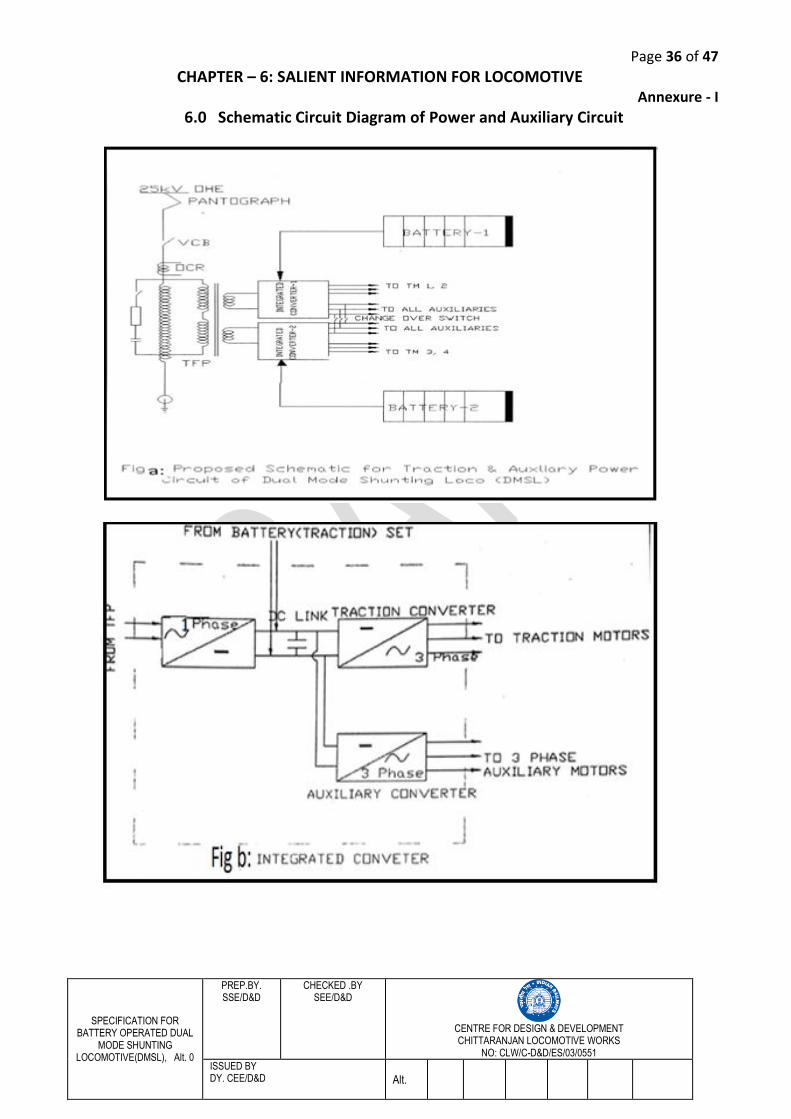
Page 36 of 47
SPECIFICATION FOR BATTERY OPERATED DUAL
MODE SHUNTING LOCOMOTIVE(DMSL), Alt. 0
PREP.BY. SSE/D&D
CHECKED .BY SEE/D&D
CENTRE FOR DESIGN & DEVELOPMENT CHITTARANJAN LOCOMOTIVE WORKS
NO: CLW/C-D&D/ES/03/0551
ISSUED BY DY. CEE/D&D Alt.
CHAPTER – 6: SALIENT INFORMATION FOR LOCOMOTIVE Annexure - I
6.0 Schematic Circuit Diagram of Power and Auxiliary Circuit
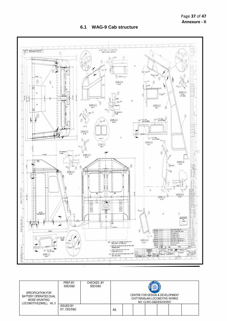
Page 37 of 47
SPECIFICATION FOR BATTERY OPERATED DUAL
MODE SHUNTING LOCOMOTIVE(DMSL), Alt. 0
PREP.BY. SSE/D&D
CHECKED .BY SEE/D&D
CENTRE FOR DESIGN & DEVELOPMENT CHITTARANJAN LOCOMOTIVE WORKS
NO: CLW/C-D&D/ES/03/0551
ISSUED BY DY. CEE/D&D Alt.
Annexure - II 6.1 WAG-9 Cab structure
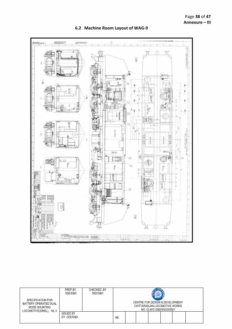
Page 38 of 47
SPECIFICATION FOR BATTERY OPERATED DUAL
MODE SHUNTING LOCOMOTIVE(DMSL), Alt. 0
PREP.BY. SSE/D&D
CHECKED .BY SEE/D&D
CENTRE FOR DESIGN & DEVELOPMENT CHITTARANJAN LOCOMOTIVE WORKS
NO: CLW/C-D&D/ES/03/0551
ISSUED BY DY. CEE/D&D Alt.
Annexure – III 6.2 Machine Room Layout of WAG-9
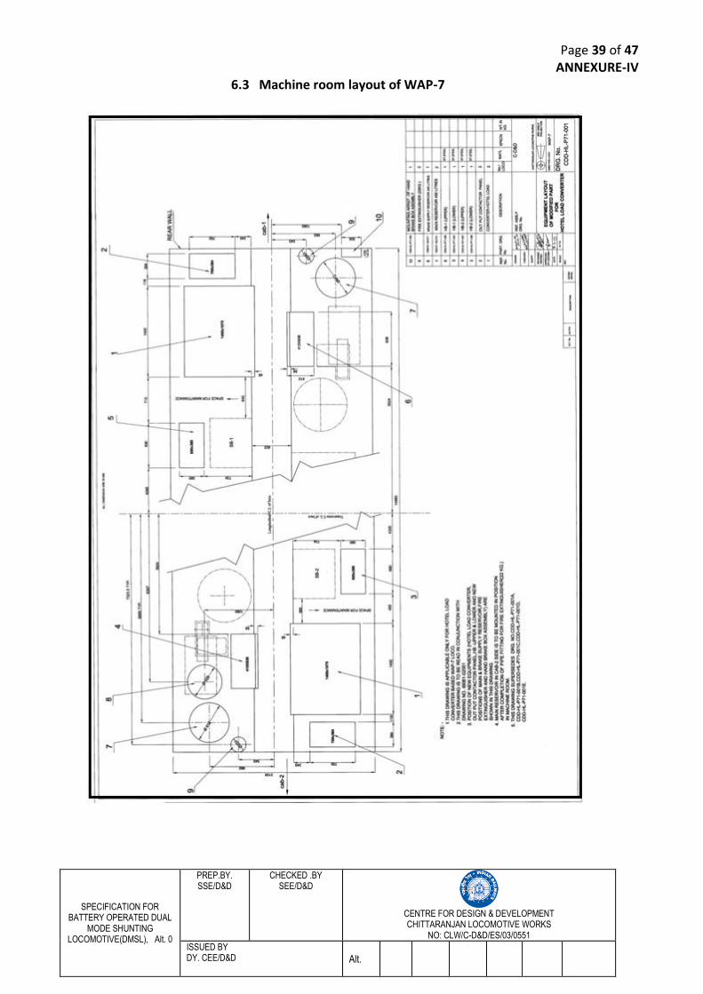
Page 39 of 47
SPECIFICATION FOR BATTERY OPERATED DUAL
MODE SHUNTING LOCOMOTIVE(DMSL), Alt. 0
PREP.BY. SSE/D&D
CHECKED .BY SEE/D&D
CENTRE FOR DESIGN & DEVELOPMENT CHITTARANJAN LOCOMOTIVE WORKS
NO: CLW/C-D&D/ES/03/0551
ISSUED BY DY. CEE/D&D Alt.
ANNEXURE-IV 6.3 Machine room layout of WAP-7
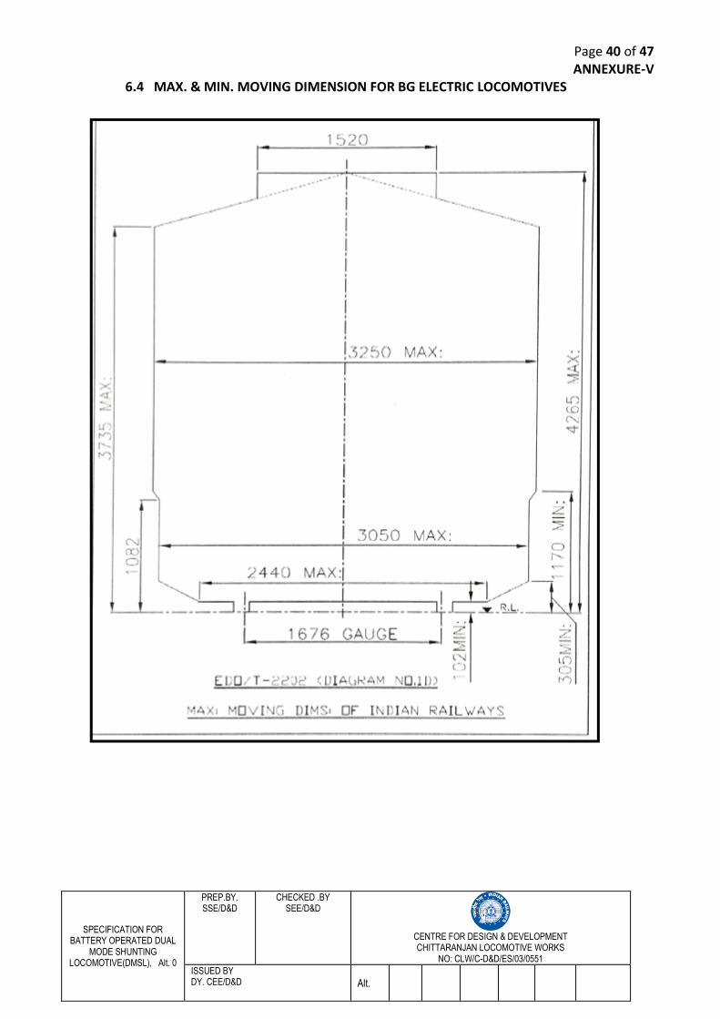
Page 40 of 47
SPECIFICATION FOR BATTERY OPERATED DUAL
MODE SHUNTING LOCOMOTIVE(DMSL), Alt. 0
PREP.BY. SSE/D&D
CHECKED .BY SEE/D&D
CENTRE FOR DESIGN & DEVELOPMENT CHITTARANJAN LOCOMOTIVE WORKS
NO: CLW/C-D&D/ES/03/0551
ISSUED BY DY. CEE/D&D Alt.
ANNEXURE-V 6.4 MAX. & MIN. MOVING DIMENSION FOR BG ELECTRIC LOCOMOTIVES
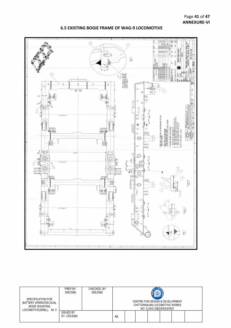
Page 41 of 47
SPECIFICATION FOR BATTERY OPERATED DUAL
MODE SHUNTING LOCOMOTIVE(DMSL), Alt. 0
PREP.BY. SSE/D&D
CHECKED .BY SEE/D&D
CENTRE FOR DESIGN & DEVELOPMENT CHITTARANJAN LOCOMOTIVE WORKS
NO: CLW/C-D&D/ES/03/0551
ISSUED BY DY. CEE/D&D Alt.
ANNEXURE-VI 6.5 EXISTING BOGIE FRAME OF WAG-9 LOCOMOTIVE
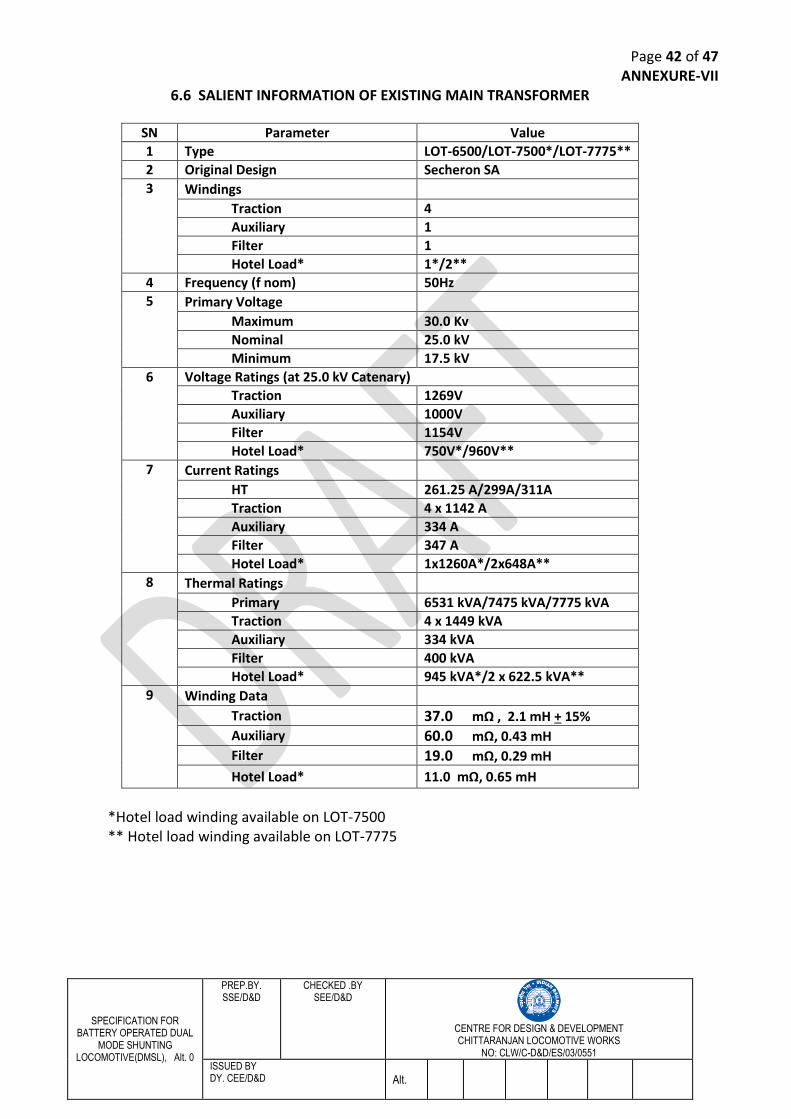
Page 42 of 47
SPECIFICATION FOR BATTERY OPERATED DUAL
MODE SHUNTING LOCOMOTIVE(DMSL), Alt. 0
PREP.BY. SSE/D&D
CHECKED .BY SEE/D&D
CENTRE FOR DESIGN & DEVELOPMENT CHITTARANJAN LOCOMOTIVE WORKS
NO: CLW/C-D&D/ES/03/0551
ISSUED BY DY. CEE/D&D Alt.
ANNEXURE-VII 6.6 SALIENT INFORMATION OF EXISTING MAIN TRANSFORMER
SN Parameter Value 1 Type LOT-6500/LOT-7500*/LOT-7775** 2 Original Design Secheron SA 3 Windings
Traction 4 Auxiliary 1 Filter 1 Hotel Load* 1*/2**
4 Frequency (f nom) 50Hz 5 Primary Voltage
Maximum 30.0 Kv Nominal 25.0 kV Minimum 17.5 kV
6 Voltage Ratings (at 25.0 kV Catenary) Traction 1269V Auxiliary 1000V Filter 1154V Hotel Load* 750V*/960V**
7 Current Ratings HT 261.25 A/299A/311A Traction 4 x 1142 A Auxiliary 334 A Filter 347 A Hotel Load* 1x1260A*/2x648A**
8 Thermal Ratings Primary 6531 kVA/7475 kVA/7775 kVA Traction 4 x 1449 kVA Auxiliary 334 kVA Filter 400 kVA Hotel Load* 945 kVA*/2 x 622.5 kVA**
9 Winding Data Traction 37.0 mΩ , 2.1 mH + 15% Auxiliary 60.0 mΩ, 0.43 mH Filter 19.0 mΩ, 0.29 mH
Hotel Load* 11.0 mΩ, 0.65 mH
*Hotel load winding available on LOT-7500 ** Hotel load winding available on LOT-7775
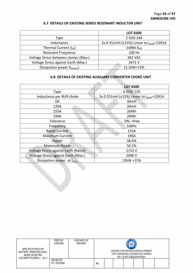
Page 43 of 47
SPECIFICATION FOR BATTERY OPERATED DUAL
MODE SHUNTING LOCOMOTIVE(DMSL), Alt. 0
PREP.BY. SSE/D&D
CHECKED .BY SEE/D&D
CENTRE FOR DESIGN & DEVELOPMENT CHITTARANJAN LOCOMOTIVE WORKS
NO: CLW/C-D&D/ES/03/0551
ISSUED BY DY. CEE/D&D Alt.
ANNEXURE-VIII 6.7 DETAILS OF EXISTING SERIES RESONANT INDUCTOR UNIT
LOT 6500
Type 2 SOD 240
Inductance 2x 0.551mH (±15%) Linear to Ipeak=1391A
Thermal Current (Ith) 2x984 Aeff
Resonant Frequency 100 Hz
Voltage Stress between clamps (Max.) 282 VAC
Voltage Stress against Earth (Max.) 3471 V
Dissipation power (Ipower) 12.5kW+15%
6.8 DETAILS OF EXISTING AUXILIARY CONVERTER CHOKE UNIT
LOT 6500
Type 6 GOD 120
Inductance per BUR choke 2x 0.551mH (±15%) Linear to Ipeak=1391A
0A 30mH
120A 30mH
155A 26Mh
190A 20Mh
Tolerance -0%, +free
Frequency 100Hz
Rated Current 155A
Maximum Current 190A
Ripple 38.6%
Maximum Ripple 50.2%
Voltage Stress against Earth (Rated) 1153 V
Voltage Stress against Earth (Max.) 2000 V
Dissipation power at Inom 12kW +15%
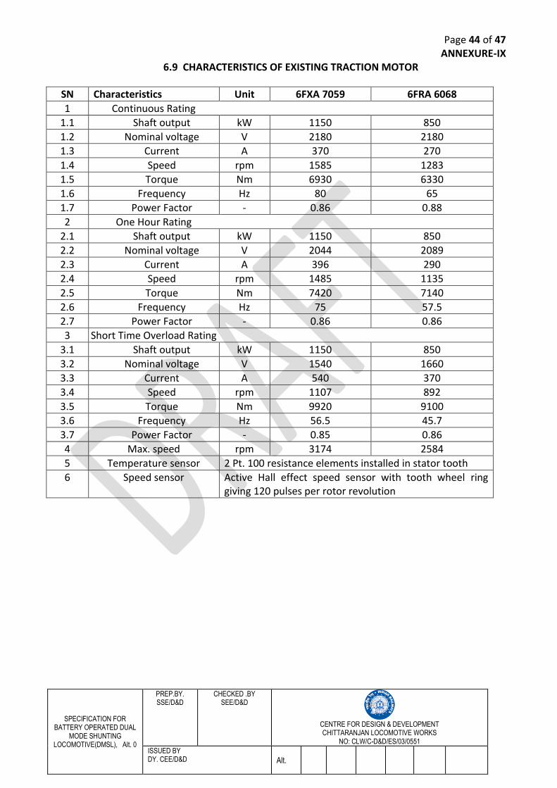
Page 44 of 47
SPECIFICATION FOR BATTERY OPERATED DUAL
MODE SHUNTING LOCOMOTIVE(DMSL), Alt. 0
PREP.BY. SSE/D&D
CHECKED .BY SEE/D&D
CENTRE FOR DESIGN & DEVELOPMENT CHITTARANJAN LOCOMOTIVE WORKS
NO: CLW/C-D&D/ES/03/0551
ISSUED BY DY. CEE/D&D Alt.
ANNEXURE-IX 6.9 CHARACTERISTICS OF EXISTING TRACTION MOTOR
SN Characteristics Unit 6FXA 7059 6FRA 6068
1 Continuous Rating
1.1 Shaft output kW 1150 850
1.2 Nominal voltage V 2180 2180
1.3 Current A 370 270
1.4 Speed rpm 1585 1283
1.5 Torque Nm 6930 6330
1.6 Frequency Hz 80 65
1.7 Power Factor - 0.86 0.88
2 One Hour Rating
2.1 Shaft output kW 1150 850
2.2 Nominal voltage V 2044 2089
2.3 Current A 396 290
2.4 Speed rpm 1485 1135
2.5 Torque Nm 7420 7140
2.6 Frequency Hz 75 57.5
2.7 Power Factor - 0.86 0.86
3 Short Time Overload Rating
3.1 Shaft output kW 1150 850
3.2 Nominal voltage V 1540 1660
3.3 Current A 540 370
3.4 Speed rpm 1107 892
3.5 Torque Nm 9920 9100
3.6 Frequency Hz 56.5 45.7
3.7 Power Factor - 0.85 0.86
4 Max. speed rpm 3174 2584
5 Temperature sensor 2 Pt. 100 resistance elements installed in stator tooth
6 Speed sensor Active Hall effect speed sensor with tooth wheel ring giving 120 pulses per rotor revolution
Page 45 of 47
SPECIFICATION FOR BATTERY OPERATED DUAL
MODE SHUNTING LOCOMOTIVE(DMSL), Alt. 0
PREP.BY. SSE/D&D
CHECKED .BY SEE/D&D
CENTRE FOR DESIGN & DEVELOPMENT CHITTARANJAN LOCOMOTIVE WORKS
NO: CLW/C-D&D/ES/03/0551
ISSUED BY DY. CEE/D&D Alt.
ANNEXURE-X 6.10 EXISTING LOAD DISTRIBUTION OF AUXILIARY CONVERTERS
When all BUR is OK:
BUR-1
Oil cooler blower-1 25 KW
Oil cooler blower-2 25 KW
Total 50 KW
BUR-2
Traction motor blower -1 25 KW
Traction motor blower -2 25 KW
Oil pump transformer – 1 4.7 KW
Oil pump transformer – 2 4.7 KW
Oil pump converter – 1 11 KW
Oil pump converter – 2 11 KW
Total 81.4 KW
BUR-3
Scavenge blower – 1 3 KW
Scavenge blower – 2 3 KW
Compressor – 1 15 KW
Compressor – 2 15 KW
Battery charger 12 KVA
Total 48 KW
When BUR-1 Isolated:
BUR-2
Traction motor blower -1 25 KW
Traction motor blower -2 25 KW
Oil cooler blower – 1 25 KW
Oil cooler blower – 2 25 KW
Scavenge blower – 1 3 KW
Scavenge blower – 2 3 KW
Total 106 KW
BUR-3
Oil pump transformer – 1 4.7 KW
Oil pump transformer – 2 4.7 KW
Oil pump converter – 1 11 KW
Oil pump converter – 2 11 KW
Compressor – 1 15 KW
Compressor – 2 15 KW
Battery charger 12 KVA
Total 73.4 KW
Page 46 of 47
SPECIFICATION FOR BATTERY OPERATED DUAL
MODE SHUNTING LOCOMOTIVE(DMSL), Alt. 0
PREP.BY. SSE/D&D
CHECKED .BY SEE/D&D
CENTRE FOR DESIGN & DEVELOPMENT CHITTARANJAN LOCOMOTIVE WORKS
NO: CLW/C-D&D/ES/03/0551
ISSUED BY DY. CEE/D&D Alt.
When BUR-2 Isolated:
BUR-1
Traction motor blower -1 25 KW
Traction motor blower -2 25 KW
Oil cooler blower – 1 25 KW
Oil cooler blower – 2 25 KW
Scavenge blower – 1 3 KW
Scavenge blower – 2 3 KW
Total 106 KW
BUR-3
Oil pump transformer – 1 4.7 KW
Oil pump transformer – 2 4.7 KW
Oil pump converter – 1 11 KW
Oil pump converter – 2 11 KW
Compressor – 1 15 KW
Compressor – 2 15 KW
Battery charger 12 KVA
Total 73.4 KW
When BUR-3 Isolated:
BUR-1
Traction motor blower -1 25 KW
Traction motor blower -2 25 KW
Oil cooler blower – 1 25 KW
Oil cooler blower – 2 25 KW
Scavenge blower – 1 3 KW
Scavenge blower – 2 3 KW
Total 106 KW
BUR-2
Oil pump transformer – 1 4.7 KW
Oil pump transformer – 2 4.7 KW
Oil pump converter – 1 11 KW
Oil pump converter – 2 11 KW
Compressor – 1 15 KW
Compressor – 2 15 KW
Battery charger 12 KVA
Total 73.4 KW
Page 47 of 47
SPECIFICATION FOR BATTERY OPERATED DUAL
MODE SHUNTING LOCOMOTIVE(DMSL), Alt. 0
PREP.BY. SSE/D&D
CHECKED .BY SEE/D&D
CENTRE FOR DESIGN & DEVELOPMENT CHITTARANJAN LOCOMOTIVE WORKS
NO: CLW/C-D&D/ES/03/0551
ISSUED BY DY. CEE/D&D Alt.
Annexure-XI 6.11 PERFORMANCE CURVE FOR BATTERY MODE OPERATION
6.12 PERFORMANCE CURVE FOR OHE MODE OPERATION