indirect-fired air heaters cub 200/300/300...
TRANSCRIPT

Indirect-fired Air Heaters
Cub 200/300/300 HD
OPERATOR’S MANUAL
0170893en 005
0309
0 1 7 0 8 9 3 E N

Cub 200/300/300 HD Table of Contents
1. Foreword 52. Safety Information 7
2.1 Operating Safety .................................................................................. 82.2 Operator Safety while using Combustion Burners ............................... 92.3 Service Safety .................................................................................... 102.4 Label Locations .................................................................................. 122.5 Label Descriptions .............................................................................. 13
3. Operation 17
3.1 System Description ............................................................................ 173.2 Installing the Lift Brackets .................................................................. 173.3 System Component Locations ........................................................... 183.4 Mounting the Handle and Base Assembly ......................................... 193.5 Machine Location ............................................................................... 203.6 Suggested Venting ............................................................................. 203.7 Connecting Power to the Machine ..................................................... 223.8 Preliminary Checks ............................................................................ 223.9 Preheating the Fuel Filter ................................................................... 223.10 Control Panel ...................................................................................... 233.11 Starting the Machine .......................................................................... 243.12 Shutting Down the Machine ............................................................... 253.13 Using the Remote Thermostat ........................................................... 26
4. Technical Data 27
4.1 Machine Technical Data ..................................................................... 27
5. Maintenance 29
5.1 Periodic Maintenance Schedule ......................................................... 295.2 Removing and Installing the Burner Assembly ................................... 305.3 Replacing the Burner Nozzle .............................................................. 325.4 Replacing the Fuel Filter .................................................................... 33
3

Table of Contents Cub 200/300/300 HD
5.5 Inspecting and Aligning the Burner Electrodes ...................................345.6 Inspecting and Cleaning the Cadmium (CAD) Cell .............................355.7 Checking and Adjusting the Fuel Pressure .........................................365.8 Cleaning the Fan Blades and Motor ....................................................385.9 Cleaning the Interior Shell ...................................................................395.10 Inspecting the Flame Head .................................................................405.11 Inspecting the Electrical Connections .................................................415.12 Fuel Blend Guide .................................................................................415.13 Transporting ........................................................................................425.14 List of Abbreviations ............................................................................435.15 Troubleshooting ...................................................................................445.16 Cub 200/300 Wiring Schematic ...........................................................465.17 Cub 300 HD Wiring Schematic ............................................................475.18 Schematic Legend ...............................................................................47wcghi_bo0170893en_001TOC.fm 4
Foreword
1 ForewordCALIFORNIAProposition 65 Warning:
Engine exhaust, some of its constituents, and certain vehiclecomponents, contain or emit chemicals known to the State ofCalifornia to cause cancer and birth defects or other reproductiveharm.
This manual provides information and procedures to safely operateand maintain this Wacker Neuson model. For your own safety andprotection from injury, carefully read, understand and observe thesafety instructions described in this manual.
Keep this manual or a copy of it with the machine. If you lose thismanual or need an additional copy, please contact Wacker NeusonCorporation. This machine is built with user safety in mind; however, itcan present hazards if improperly operated and serviced. Followoperating instructions carefully! If you have questions about operatingor servicing this equipment, please contact Wacker NeusonCorporation.
The information contained in this manual was based on machines inproduction at the time of publication. Wacker Neuson Corporationreserves the right to change any portion of this information withoutnotice.
All rights, especially copying and distribution rights, are reserved.
Copyright 2009 by Wacker Neuson Corporation.
No part of this publication may be reproduced in any form or by anymeans, electronic or mechanical, including photocopying, withoutexpress written permission from Wacker Neuson Corporation.
Any type of reproduction or distribution not authorized by WackerNeuson Corporation represents an infringement of valid copyrightsand will be prosecuted. We expressly reserve the right to maketechnical modifications, even without due notice, which aim atimproving our machines or their safety standards.
WARNING
wcghi_tx000001gb diesel.fm 5

Foreword
wcghi_tx000001gb diesel.fm 6
Cub 200/300/300 HD Safety Information
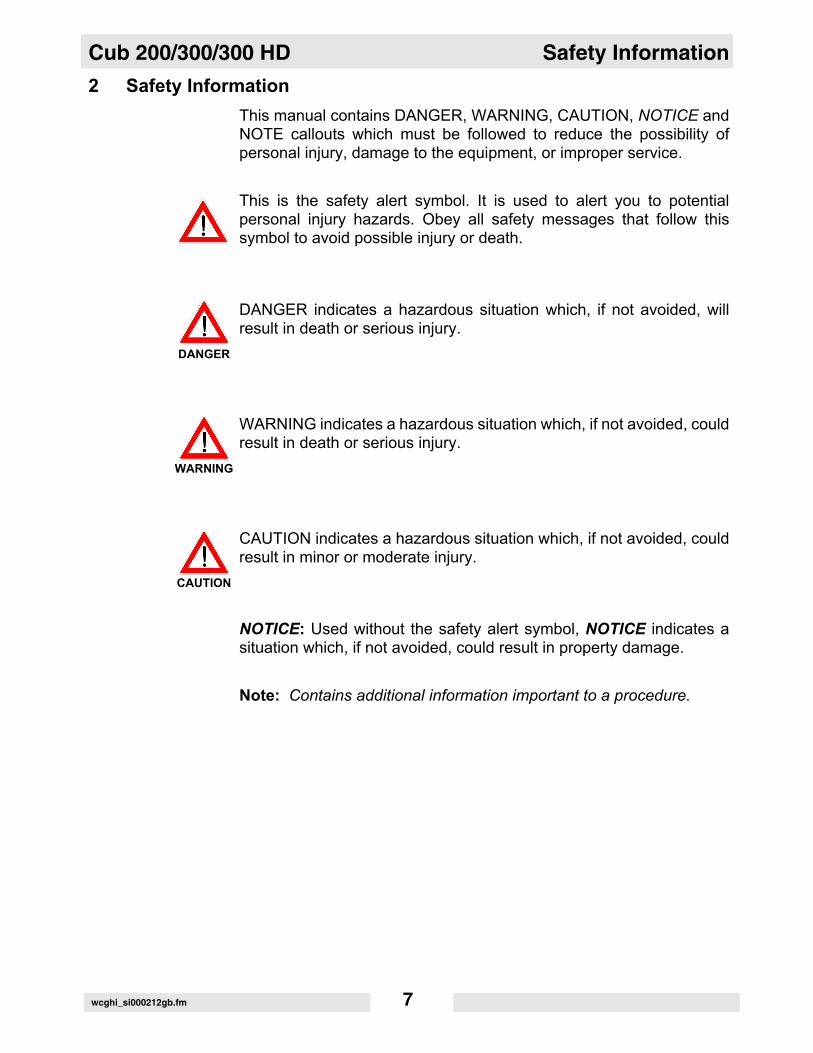
2 Safety InformationThis manual contains DANGER, WARNING, CAUTION, NOTICE andNOTE callouts which must be followed to reduce the possibility ofpersonal injury, damage to the equipment, or improper service.
This is the safety alert symbol. It is used to alert you to potentialpersonal injury hazards. Obey all safety messages that follow thissymbol to avoid possible injury or death.
DANGER indicates a hazardous situation which, if not avoided, willresult in death or serious injury.
WARNING indicates a hazardous situation which, if not avoided, couldresult in death or serious injury.
CAUTION indicates a hazardous situation which, if not avoided, couldresult in minor or moderate injury.
NOTICE: Used without the safety alert symbol, NOTICE indicates asituation which, if not avoided, could result in property damage.
Note: Contains additional information important to a procedure.
DANGER
WARNING
CAUTION
wcghi_si000212gb.fm 7
Safety Information Cub 200/300/300 HD
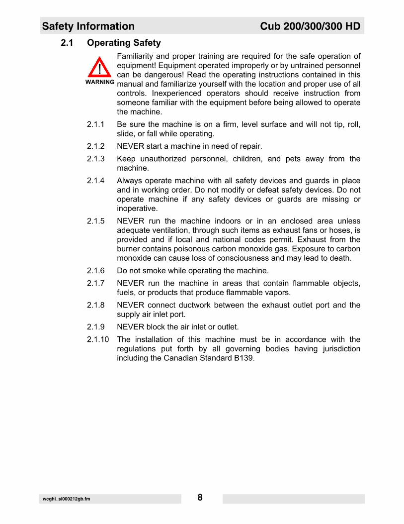
2.1 Operating SafetyFamiliarity and proper training are required for the safe operation ofequipment! Equipment operated improperly or by untrained personnelcan be dangerous! Read the operating instructions contained in thismanual and familiarize yourself with the location and proper use of allcontrols. Inexperienced operators should receive instruction fromsomeone familiar with the equipment before being allowed to operatethe machine.
2.1.1 Be sure the machine is on a firm, level surface and will not tip, roll,slide, or fall while operating.
2.1.2 NEVER start a machine in need of repair.2.1.3 Keep unauthorized personnel, children, and pets away from the
machine.2.1.4 Always operate machine with all safety devices and guards in place
and in working order. Do not modify or defeat safety devices. Do notoperate machine if any safety devices or guards are missing orinoperative.
2.1.5 NEVER run the machine indoors or in an enclosed area unlessadequate ventilation, through such items as exhaust fans or hoses, isprovided and if local and national codes permit. Exhaust from theburner contains poisonous carbon monoxide gas. Exposure to carbonmonoxide can cause loss of consciousness and may lead to death.
2.1.6 Do not smoke while operating the machine.2.1.7 NEVER run the machine in areas that contain flammable objects,
fuels, or products that produce flammable vapors.2.1.8 NEVER connect ductwork between the exhaust outlet port and the
supply air inlet port.2.1.9 NEVER block the air inlet or outlet.2.1.10 The installation of this machine must be in accordance with the
regulations put forth by all governing bodies having jurisdictionincluding the Canadian Standard B139.
WARNING
wcghi_si000212gb.fm 8
Cub 200/300/300 HD Safety Information
2.2 Operator Safety while using Combustion Burners2.2.1 Refill the fuel tank in a well-ventilated area.2.2.2 Replace the fuel tank cap after refueling.2.2.3 DO NOT spill fuel when refueling the machine. Clean up spilled fuel
immediately.2.2.4 DO NOT smoke when refueling machine.2.2.5 DO NOT refuel a hot or running machine.2.2.6 The machine must be installed by qualified personnel who have read
and understand all supplied manuals and instructions.2.2.7 When operating the machine indoors, install a carbon monoxide
detector in the work area according to the detector manufacturer’sinstructions.
wcghi_si000212gb.fm 9
Safety Information Cub 200/300/300 HD
2.3 Service SafetyHIGH VOLTAGE! This unit uses high voltage circuits capable ofcausing serious injury or death. Only a qualified electrician shouldtroubleshoot or repair electrical problems occurring with thisequipment.
2.3.1 ALWAYS replace the safety devices and guards after repairs andmaintenance.
2.3.2 Keep the machine clean and labels legible. Replace all missing andhard-to-read labels. Labels provide important operating instructionsand warn of dangers and hazards.
2.3.3 ALWAYS make sure slings, chains, hooks, ramps, jacks, and othertypes of lifting devices are attached securely and have enough weight-bearing capacity to lift or hold the machine safely. Always remainaware of the location of other people in the area when lifting themachine.
2.3.4 ALWAYS replace or repair electrical components with componentsthat are identical in rating and performance as the original component.
2.3.5 Do not use gasoline or other types of fuels or flammable solvents toclean parts, especially in enclosed areas. Fumes from fuels andsolvents can become explosive.
2.3.6 Always wear protective epuipment when servicing the machine. Somemachine components may be hot and contain hot fluids.
WARNING
wcghi_si000212gb.fm 10

Cub 200/300/300 HD Safety Information
Notes:wcghi_si000212gb.fm 11
Safety Information Cub 200/300/300 HD
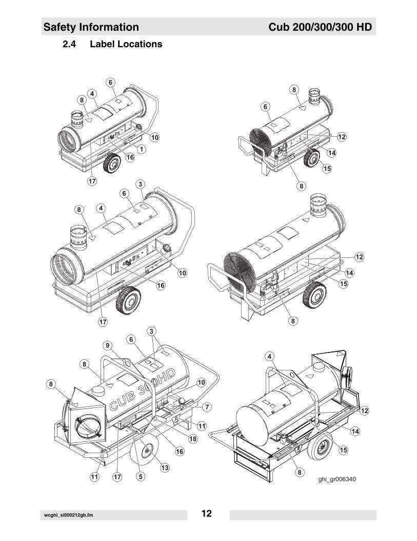
2.4 Label Locationswcghi_si000212gb.fm 12
Cub 200/300/300 HD Safety Information
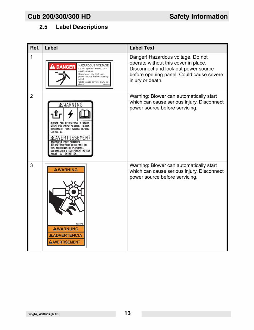
2.5 Label DescriptionsRef. Label Label Text
1 Danger! Hazardous voltage. Do not operate without this cover in place. Disconnect and lock out power source before opening panel. Could cause severe injury or death.
2 Warning: Blower can automatically start which can cause serious injury. Disconnect power source before servicing.
3 Warning: Blower can automatically start which can cause serious injury. Disconnect power source before servicing.
WARNING
WARNUNG
ADVERTENCIA
AVERTISSEMENT
177370
wcghi_si000212gb.fm 13
Safety Information Cub 200/300/300 HD
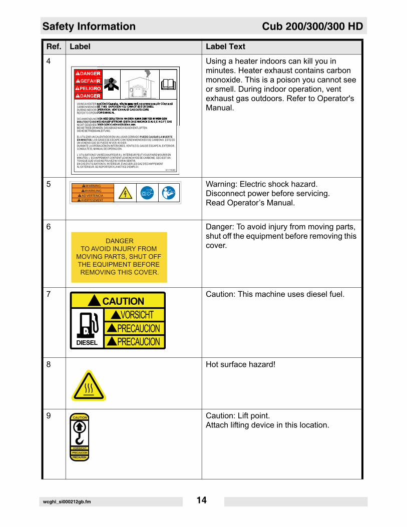
4 Using a heater indoors can kill you in minutes. Heater exhaust contains carbon monoxide. This is a poison you cannot see or smell. During indoor operation, vent exhaust gas outdoors. Refer to Operator's Manual.
5 Warning: Electric shock hazard. Disconnect power before servicing. Read Operator’s Manual.
6 Danger: To avoid injury from moving parts, shut off the equipment before removing this cover.
7 Caution: This machine uses diesel fuel.
8 Hot surface hazard!
9 Caution: Lift point.Attach lifting device in this location.
Ref. Label Label Text
DANGERTO AVOID INJURY FROM
MOVING PARTS, SHUT OFF THE EQUIPMENT BEFORE REMOVING THIS COVER.
D
DIESEL
CAUTIONVORSICHT
PRECAUCIONPRECAUCION
�
�
�
�
CAUTION
VORSICHTPRECAUCION
PRECAUTION
wcghi_si000212gb.fm 14
Cub 200/300/300 HD Safety Information
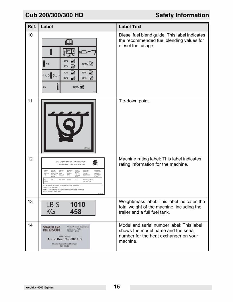
10 Diesel fuel blend guide. This label indicates the recommended fuel blending values for diesel fuel usage.
11 Tie-down point.
12 Machine rating label: This label indicates rating information for the machine.
13 Weight/mass label: This label indicates the total weight of the machine, including the trailer and a full fuel tank.
14 Model and serial number label: This label shows the model name and the serial number for the heat exchanger on your machine.
Ref. Label Label Text
wcghi_si000212gb.fm 15
Safety Information Cub 200/300/300 HD
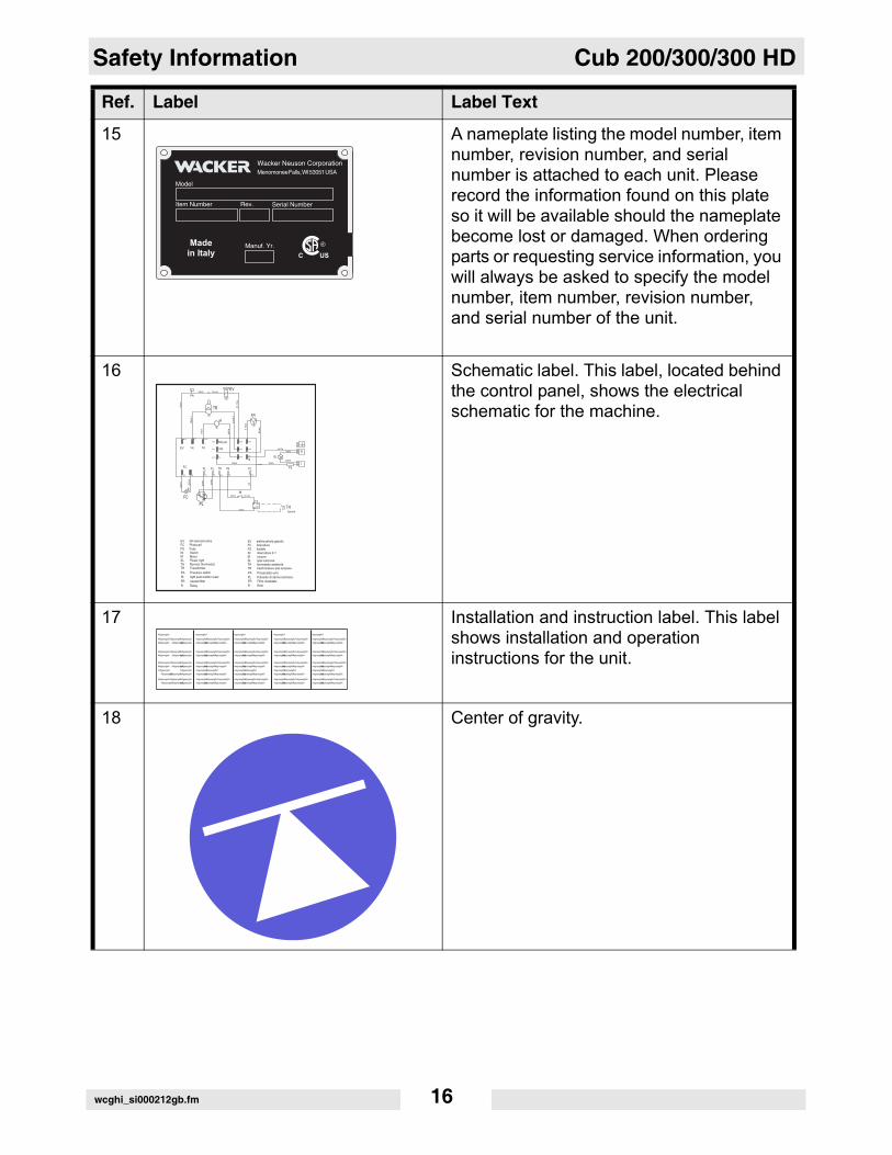
15 A nameplate listing the model number, item number, revision number, and serial number is attached to each unit. Please record the information found on this plate so it will be available should the nameplate become lost or damaged. When ordering parts or requesting service information, you will always be asked to specify the model number, item number, revision number, and serial number of the unit.
16 Schematic label. This label, located behind the control panel, shows the electrical schematic for the machine.
17 Installation and instruction label. This label shows installation and operation instructions for the unit.
18 Center of gravity.
Ref. Label Label Text
wcghi_si000212gb.fm 16
Cub 200/300/300 HD Operation
3 Operation3.1 System Description
The Cub series Air Heater machines are indirect-fired air heaters. TheCub series Air Heater machines incorporate aluminized steel shellsand heat exchangers. The machines run on three fuel options: diesel,Kerosene, or winter blend diesel (winter blend diesel is treated withanti-gelling conditioners for use in cold weather). The fuel is consumedin a closed combustion chamber. The exhaust gasses must be ventedoutdoors through a vent pipe. The clean, dry hot air is recirculated bymeans of an enclosed blower. The Cub series Air Heater machines are intended to heat air onconstruction sites and in other rugged environments. Do not use themachines for any other purpose.
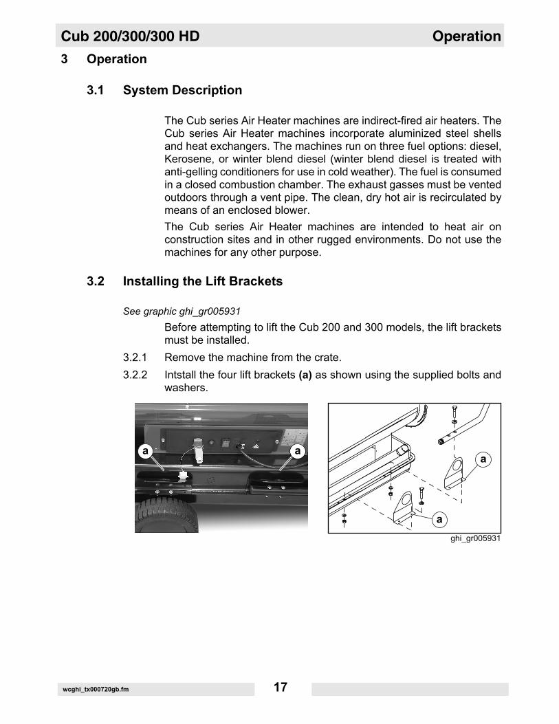
3.2 Installing the Lift Brackets
See graphic ghi_gr005931Before attempting to lift the Cub 200 and 300 models, the lift bracketsmust be installed.
3.2.1 Remove the machine from the crate. 3.2.2 Intstall the four lift brackets (a) as shown using the supplied bolts and
washers.
wcghi_tx000720gb.fm 17
Operation Cub 200/300/300 HD
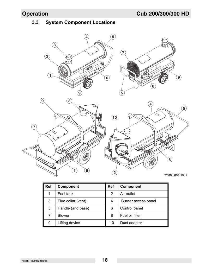
3.3 System Component LocationsRef Component Ref Component
1 Fuel tank 2 Air outlet
3 Flue collar (vent) 4 Burner access panel
5 Handle (and base) 6 Control panel
7 Blower 8 Fuel oil filter
9 Lifting device 10 Duct adapter
wcghi_tx000720gb.fm 18
Cub 200/300/300 HD Operation
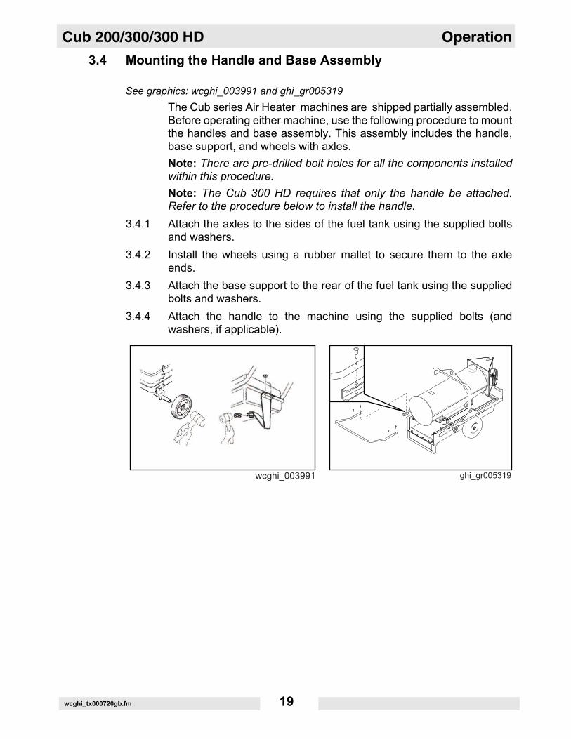
3.4 Mounting the Handle and Base AssemblySee graphics: wcghi_003991 and ghi_gr005319The Cub series Air Heater machines are shipped partially assembled.Before operating either machine, use the following procedure to mountthe handles and base assembly. This assembly includes the handle,base support, and wheels with axles. Note: There are pre-drilled bolt holes for all the components installedwithin this procedure.Note: The Cub 300 HD requires that only the handle be attached.Refer to the procedure below to install the handle.
3.4.1 Attach the axles to the sides of the fuel tank using the supplied boltsand washers.
3.4.2 Install the wheels using a rubber mallet to secure them to the axleends.
3.4.3 Attach the base support to the rear of the fuel tank using the suppliedbolts and washers.
3.4.4 Attach the handle to the machine using the supplied bolts (andwashers, if applicable).
wcghi_tx000720gb.fm 19
Operation Cub 200/300/300 HD
3.5 Machine LocationThe Air Heater machines may be located outdoors or in anyenvironment that requires heating. When locating a machine within thearea to be heated, the exhaust gases must be vented to the outdoors. The machines must be installed:• By qualified personnel who have read and understood all
supplied instructions.• On a flat, firm surface.• With the following minimum clearances:
• 3.05 m (10 ft.) to front.• 0.61 m (2 ft.) to rear.• 0.61 m (2 ft.) to sides.• 1.52 m (5 ft.) to top.• 0.915 m (3 ft.) to flue pipe.
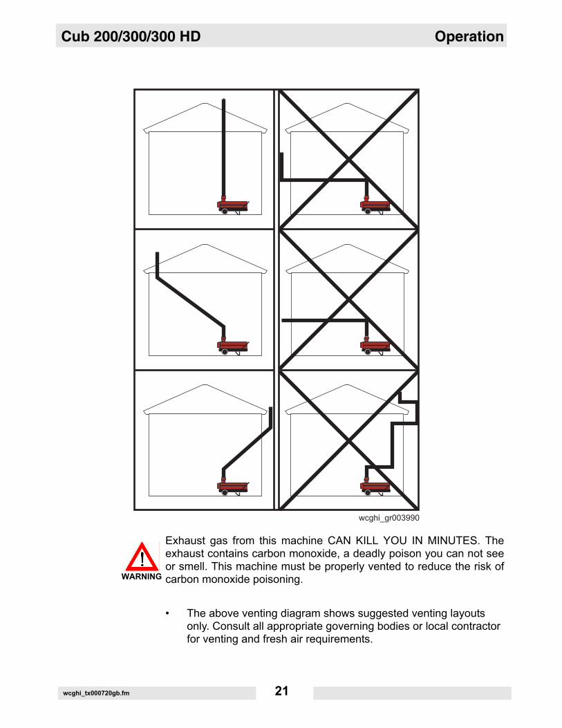
3.6 Suggested Venting
See Graphic: wcghi_gr003990Exhaust gas from this machine CAN KILL YOU IN MINUTES. Theexhaust contains carbon monoxide, a deadly poison you can not seeor smell. This machine must be properly vented to reduce the risk ofcarbon monoxide poisoning.
When installing vents:• Adhere to all local and national codes.• Consult all appropriate governing bodies or local contractor for
venting and fresh air requirements.• Place the machine in a manner that avoids excessive vent bends
(elbows), and long horizontal runs.• Keep air inlets and outlets free from obstruction. • Route the venting pipes in a manner that avoids any flammable
material. • Route the venting pipes in a manner that avoids contact with
humans.
WARNING
wcghi_tx000720gb.fm 20
Cub 200/300/300 HD Operation
Exhaust gas from this machine CAN KILL YOU IN MINUTES. Theexhaust contains carbon monoxide, a deadly poison you can not seeor smell. This machine must be properly vented to reduce the risk ofcarbon monoxide poisoning.
• The above venting diagram shows suggested venting layouts only. Consult all appropriate governing bodies or local contractor for venting and fresh air requirements.
WARNING
wcghi_tx000720gb.fm 21
Operation Cub 200/300/300 HD
3.7 Connecting Power to the MachineFire and electric shock hazard. High voltage can cause severe injuryor death. This unit must be electrically grounded. Do NOT useadapters.
The Air Heater machines come equipped with power cords. Connectthe power cord to a grounded outlet rated 115V 60 Hz.
3.8 Preliminary Checks
Before starting the machine, check the following:• Fuel supply on diesel burning machines. See Fuel Blend Guide.• Position of power switch. It must be in the Off (“O”) position.• Power supply. The machine must be connected to a 115V 60Hz
power supply.• Machine location. Ensure that the machine is properly located
according to the Machine Location guidelines in this manual.• Remote thermostat connection. If the remote thermostat will not
be used, the remote thermostat receptacle cover must be installed.
3.9 Preheating the Fuel Filter
In low ambient temperatures, it may be necessary to preheat the fuelinside the fuel filter canister. The fuel filter contains a low-wattageheating element specifically designed for this purpose.
Hot surface hazard. The external surface of the fuel filter may be hot. • Wear safety gloves when handling the fuel filter.
Note: Excess heating may increase the need for maintenance. Seesections “Replacing the Fuel Filter” and “Replacing the Burner Nozzle”.To preheat the fuel (in the fuel filter), carry out the following procedure.
3.9.1 Connect power to the machine. See section Connecting Power to theMachine.
3.9.2 Wait 10-30 minutes.3.9.3 Start the machine. See section Starting the Machine.
WARNING
CAUTION
wcghi_tx000720gb.fm 22

Cub 200/300/300 HD Operation
3.10 Control PanelRef Component Function
a Remote thermostat receptacle
The remote thermostat receptacle (shown with protective cap installed) is used for connecting an optional remotethermostat
b Burner fault lamp and reset button (dual function).
The dual function burner fault lamp and reset button:• illuminates red when the burner has
faulted.• resets the machine when pressed.
c Power switch The power switch provides power to the machine.
d Power cord The power cord provides a means of connecting the machine to a 115V 60 Hz receptacle.
e Power indicator lamp The power indicator lamp illuminates green when the power cord is connected to a 115V 60 Hz receptacle.
wcghi_tx000720gb.fm 23
Operation Cub 200/300/300 HD
3.11 Starting the Machine3.11.1 Perform the necessary preliminary checks. See section PreliminaryChecks.
3.11.2 If using the remote thermostat, connect it to the control panel at theremote thermostat receptacle. Place the remote thermostat in the areato be heated. Set it to the desired temperature.
3.11.3 Move the power switch to the On “I” position. • The blower will turn on immediately.• The burner will go through a prepurge cycle and then light.• The burner will continue to fire until the temperature of the space
being heated reaches the temperature set by the thermostat. At that time, the burner shuts down but the blower will remain on.
• If not using the remote thermostat, the blower will continue to operate until shutdown.
wcghi_tx000720gb.fm 24
Cub 200/300/300 HD Operation
3.12 Shutting Down the MachineElectric shock and cutting injury hazard! At temperatures above 104°F(40°C), electric power is available at the supply blower even with theoperation mode switch in the OFF position. Always remove all powerto the machine before servicing it.
3.12.1 Move the power switch to the Off (“O”) position.Note: The burner will shut down; however, the fan will continue tooperate for approximately two minutes to allow the combustionchamber to cool.
3.12.2 When the blower has shut off automatically, disconnect the powersupply cord.
3.12.3 Disconnect the remote thermostat and re-install the receptacle cover.
WARNING
wcghi_tx000720gb.fm 25
Operation Cub 200/300/300 HD
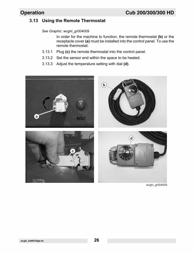
3.13 Using the Remote ThermostatSee Graphic: wcghi_gr004009In order for the machine to function, the remote thermostat (b) or thereceptacle cover (a) must be installed into the control panel. To use theremote thermostat:
3.13.1 Plug (c) the remote thermostat into the control panel.3.13.2 Set the sensor end within the space to be heated.3.13.3 Adjust the temperature setting with dial (d).
wcghi_tx000720gb.fm 26
Cub 200/300/300 HD Technical Data
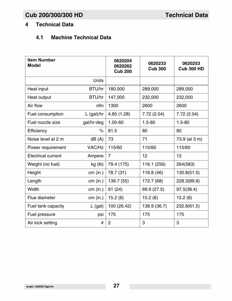
4 Technical Data4.1 Machine Technical Data
Item NumberModel
06202040620262Cub 200
0620233Cub 300
0620253Cub 300 HD
Units
Heat input BTU/hr 180,000 289,000 289,000
Heat output BTU/hr 147,000 232,000 232,000
Air flow cfm 1300 2600 2600
Fuel consumption L (gal)/hr 4.85 (1.28) 7.72 (2.04) 7.72 (2.04)
Fuel nozzle size gal/hr-deg 1.00-60 1.5-80 1.5-80
Efficiency % 81.5 80 80
Noise level at 2 m dB (A) 73 71 73.9 (at 3 m)
Power requirement VAC/Hz 115/60 115/60 115/60
Electrical current Ampere 7 12 12
Weight (no fuel) kg (lb) 79.4 (175) 116.1 (256) 264(583)
Height cm (in.) 78.7 (31) 116.8 (46) 130.8(51.5)
Length cm (in.) 139.7 (55) 172.7 (68) 228.3(89.9)
Width cm (in.) 61 (24) 69.9 (27.5) 97.5(38.4)
Flue diameter cm (in.) 15.2 (6) 15.2 (6) 15.2 (6)
Fuel tank capacity L (gal) 100 (26.42) 138.9 (36.7) 232.8(61.5)
Fuel pressure psi 175 175 175
Air lock setting # 2 3 3
wcghi_td000213gb.fm 27

Technical Data Cub 200/300/300 HD
wcghi_td000213gb.fm 28
Cub 200/300/300 HD Maintenance
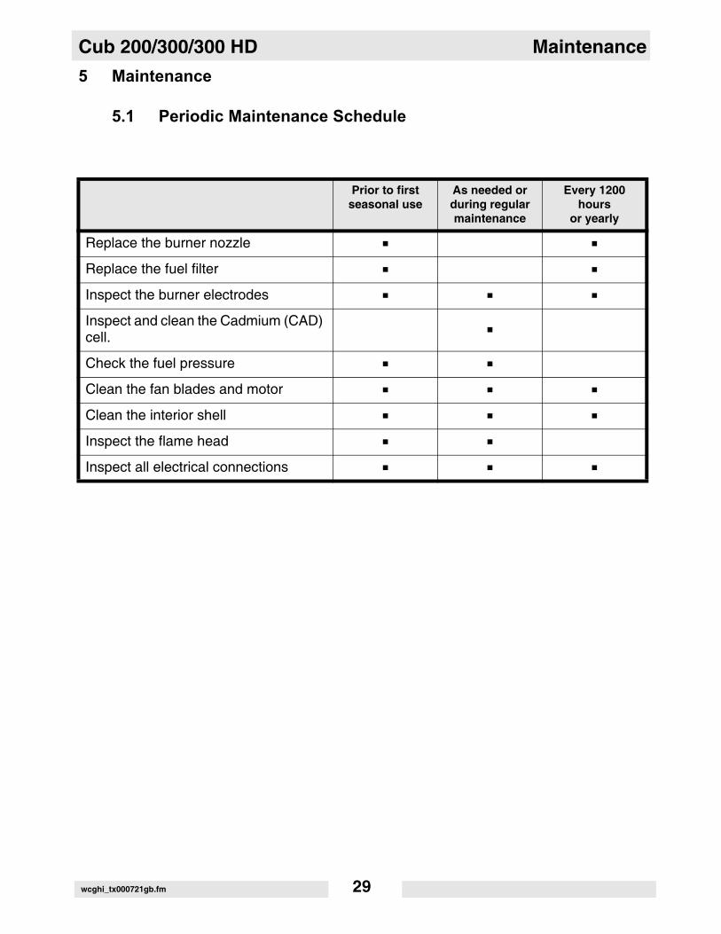
5 Maintenance5.1 Periodic Maintenance Schedule
Prior to first seasonal use
As needed or during regular maintenance
Every 1200 hours
or yearly
Replace the burner nozzle
Replace the fuel filter
Inspect the burner electrodes
Inspect and clean the Cadmium (CAD) cell.
Check the fuel pressure
Clean the fan blades and motor
Clean the interior shell
Inspect the flame head
Inspect all electrical connections
wcghi_tx000721gb.fm 29
Maintenance Cub 200/300/300 HD
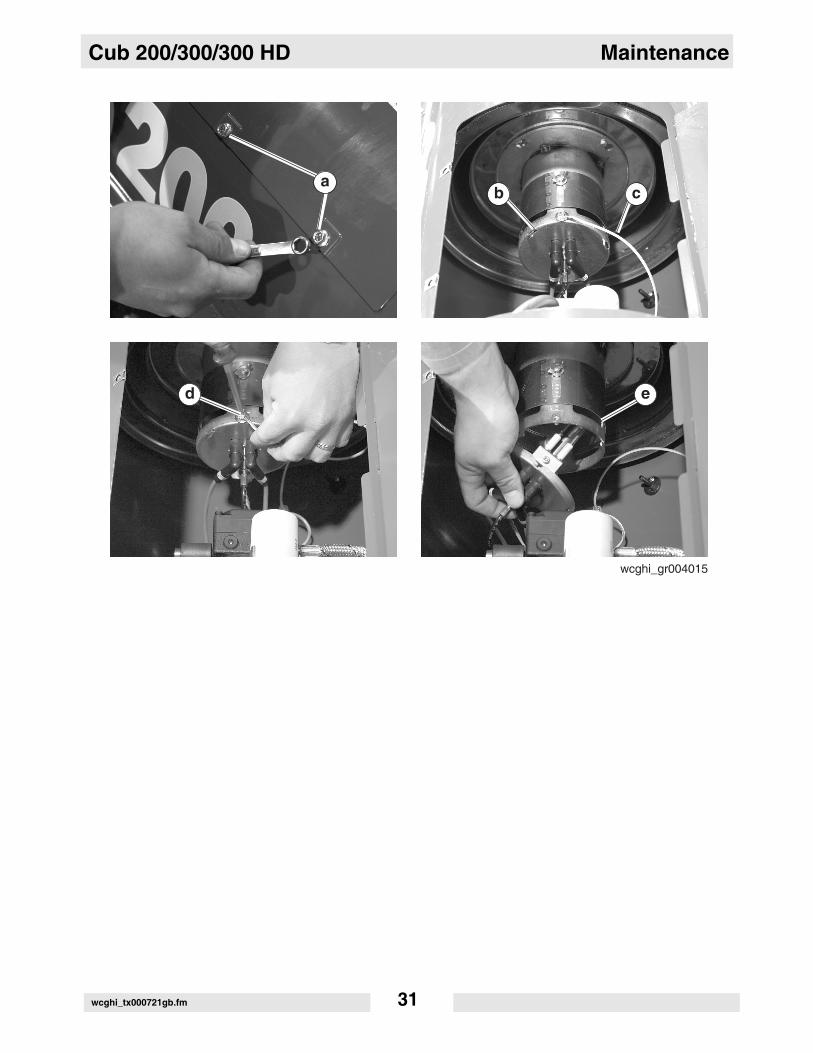
5.2 Removing and Installing the Burner AssemblySee graphic: wcghi_gr004015Before performing any maintenance on the burner assembly, it mustbe removed from the machine. To remove or install the burnerassembly refer the following procedure:Removal:
5.2.1 Shut down the machine and allow it to cool.
5.2.2 Disconnect the power cord from the power source.
5.2.3 Remove the two bolts (a) and open the access panel.5.2.4 Remove the screw (d) to disconnect the ground wire (c) from the
burner assembly.
5.2.5 Rotate the burner assembly (b) counter-clockwise and remove it fromthe flame head and air tube assembly (e).
5.2.6 Perform the required maintenance. Note: Refer the maintenance procedures in this manual.
5.2.7 Re-install the burner assembly. Refer to the steps below to install theburner assembly.
Installation:
5.2.8 Place the burner assembly into the flame head and air tube assembly(e).
5.2.9 Rotate the burner assembly clockwise to lock it into place.
5.2.10 Install the ground wire (c) using the screw (d).5.2.11 Close the access panel and re-install the two bolts (a) that secure the
panel.
wcghi_tx000721gb.fm 30
Cub 200/300/300 HD Maintenance
wcghi_tx000721gb.fm 31

Maintenance Cub 200/300/300 HD
5.3 Replacing the Burner NozzleSee Graphic: wcghi_gr004016To replace the burner nozzle, carry out the following procedure:Removal:
5.3.1 Remove the burner. See section Removing and Installing the BurnerAssembly.
5.3.2 Place an adjustable wrench on the large fitting (1) on the nozzle base(3).
5.3.3 Place another adjustable wrench on the nozzle (2).5.3.4 Rotate the nozzle counter-clockwise and remove it from the assembly.
Installation:5.3.5 Install the new nozzle (2) onto the nozzle base (3).5.3.6 Tighten the nozzle (2) using an adjustable wrench. Rotate the wrench
clockwise.5.3.7 Re-install the burner assembly. See section Removing and Installing
the Burner Assembly.
wcghi_tx000721gb.fm 32
Cub 200/300/300 HD Maintenance
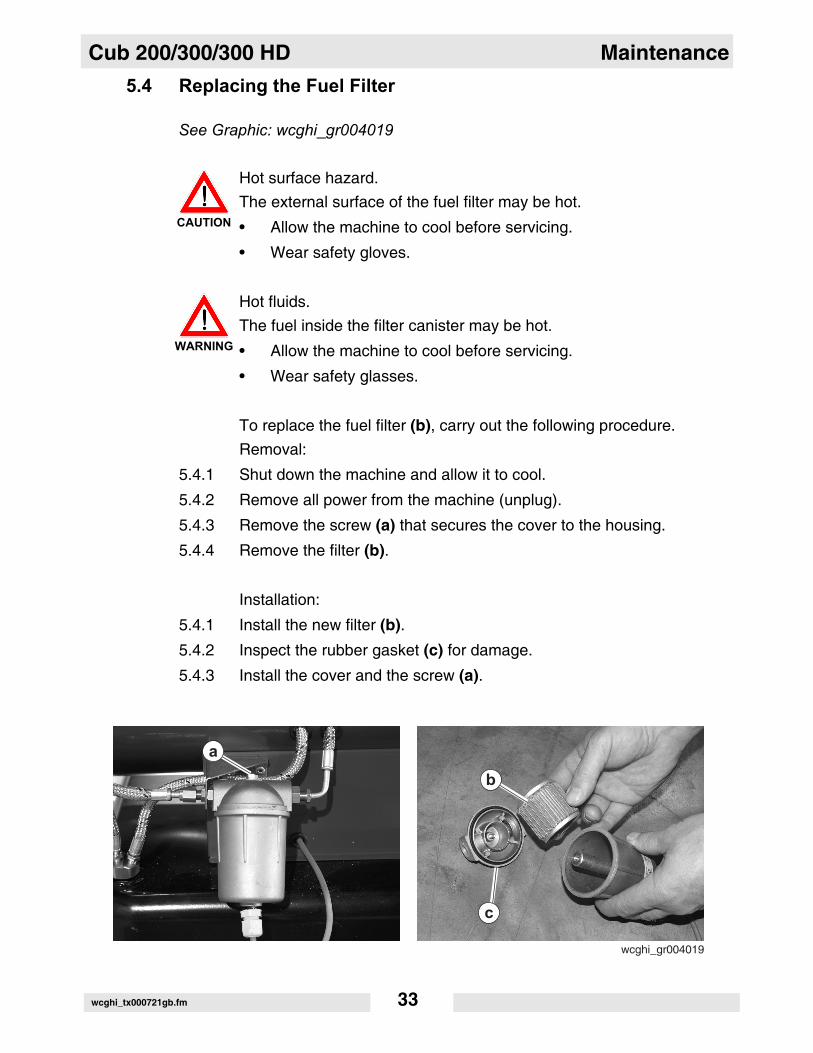
5.4 Replacing the Fuel FilterSee Graphic: wcghi_gr004019
Hot surface hazard. The external surface of the fuel filter may be hot.
• Allow the machine to cool before servicing.
• Wear safety gloves.
Hot fluids. The fuel inside the filter canister may be hot.
• Allow the machine to cool before servicing.
• Wear safety glasses.
To replace the fuel filter (b), carry out the following procedure.Removal:
5.4.1 Shut down the machine and allow it to cool.
5.4.2 Remove all power from the machine (unplug).
5.4.3 Remove the screw (a) that secures the cover to the housing.
5.4.4 Remove the filter (b).
Installation:
5.4.1 Install the new filter (b).5.4.2 Inspect the rubber gasket (c) for damage.
5.4.3 Install the cover and the screw (a).
CAUTION
WARNING
wcghi_tx000721gb.fm 33
Maintenance Cub 200/300/300 HD
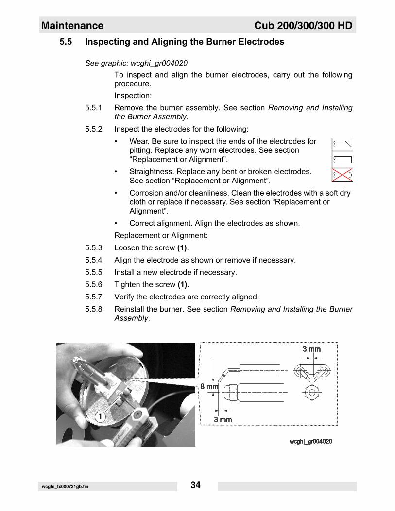
5.5 Inspecting and Aligning the Burner ElectrodesSee graphic: wcghi_gr004020To inspect and align the burner electrodes, carry out the followingprocedure.Inspection:
5.5.1 Remove the burner assembly. See section Removing and Installingthe Burner Assembly.
5.5.2 Inspect the electrodes for the following:• Wear. Be sure to inspect the ends of the electrodes for
pitting. Replace any worn electrodes. See section “Replacement or Alignment”.
• Straightness. Replace any bent or broken electrodes. See section “Replacement or Alignment”.
• Corrosion and/or cleanliness. Clean the electrodes with a soft dry cloth or replace if necessary. See section “Replacement or Alignment”.
• Correct alignment. Align the electrodes as shown.Replacement or Alignment:
5.5.3 Loosen the screw (1).5.5.4 Align the electrode as shown or remove if necessary.5.5.5 Install a new electrode if necessary.5.5.6 Tighten the screw (1).5.5.7 Verify the electrodes are correctly aligned.5.5.8 Reinstall the burner. See section Removing and Installing the Burner
Assembly.
wcghi_tx000721gb.fm 34
Cub 200/300/300 HD Maintenance
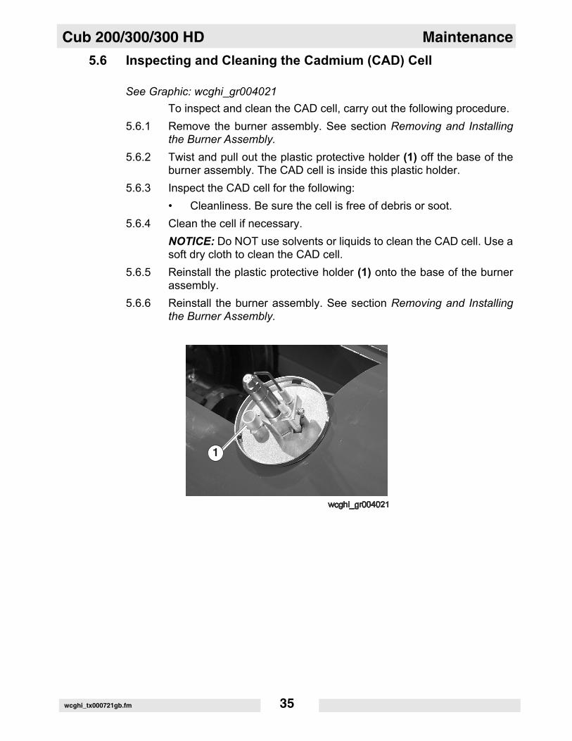
5.6 Inspecting and Cleaning the Cadmium (CAD) CellSee Graphic: wcghi_gr004021To inspect and clean the CAD cell, carry out the following procedure.
5.6.1 Remove the burner assembly. See section Removing and Installingthe Burner Assembly.
5.6.2 Twist and pull out the plastic protective holder (1) off the base of theburner assembly. The CAD cell is inside this plastic holder.
5.6.3 Inspect the CAD cell for the following:• Cleanliness. Be sure the cell is free of debris or soot.
5.6.4 Clean the cell if necessary.NOTICE: Do NOT use solvents or liquids to clean the CAD cell. Use asoft dry cloth to clean the CAD cell.
5.6.5 Reinstall the plastic protective holder (1) onto the base of the burnerassembly.
5.6.6 Reinstall the burner assembly. See section Removing and Installingthe Burner Assembly.
wcghi_tx000721gb.fm 35
Maintenance Cub 200/300/300 HD
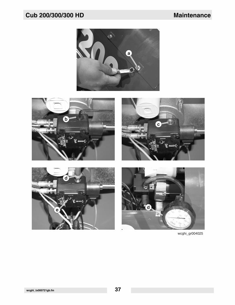
5.7 Checking and Adjusting the Fuel PressureSee Graphic: wcghi_gr004025To check the fuel pressure a pressure gauge is needed. To check and/or adjust the fuel pressure, carry out the following procedure:
5.7.1 Shut down the machine and allow it to cool.5.7.2 Disconnect the power cord from the power source.5.7.3 Remove the two bolts (a) and open the access panel.5.7.4 Remove the threaded plug (b) from the pressure test port using an
allen wrench. Set the plug in a safe location to be re-installed later.5.7.5 Install a pressure gauge in the threaded pressure test port (c). 5.7.6 Start the machine. See section Starting the Machine.5.7.7 With the machine running, verify the fuel pressure setting. For the
correct settings, refer to the Technical Data charts in this manual.5.7.8 Shut down the machine. See section Shutting Down the Machine.5.7.9 Adjust the fuel pressure if necessary using the adjusting screw (e) and
re-check the settings. Repeat steps 6-8 to re-check the settings.
Do not adjust the fuel pressure to a setting outside the safe operationalparameters.
5.7.10 Remove the pressure gauge (d) from the pressure test port (c).5.7.11 Re-install the threaded plug (b) into the pressure test port (c).5.7.12 Close the access panel and re-install the two bolts (a) that secure the
panel.
wcghi_tx000721gb.fm 36
Cub 200/300/300 HD Maintenance
wcghi_tx000721gb.fm 37
Maintenance Cub 200/300/300 HD
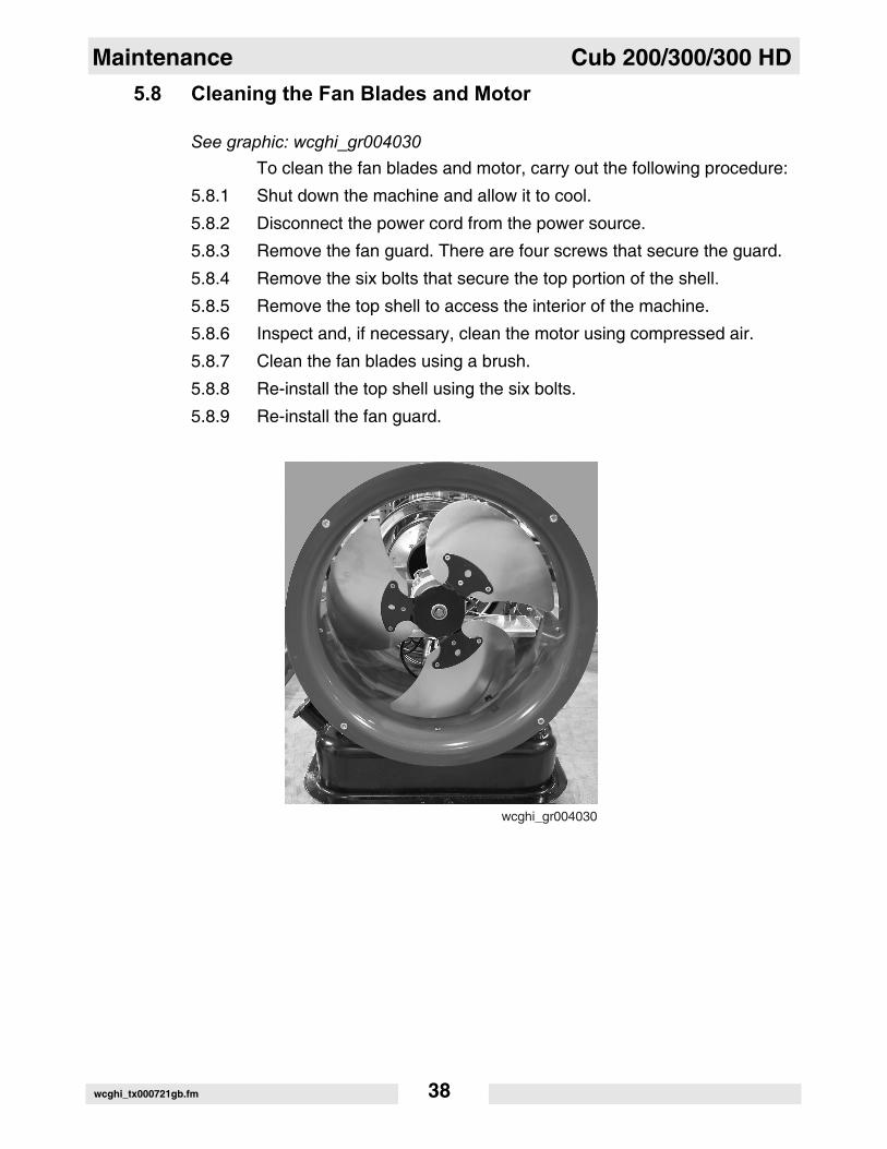
5.8 Cleaning the Fan Blades and MotorSee graphic: wcghi_gr004030To clean the fan blades and motor, carry out the following procedure:
5.8.1 Shut down the machine and allow it to cool.
5.8.2 Disconnect the power cord from the power source.
5.8.3 Remove the fan guard. There are four screws that secure the guard.
5.8.4 Remove the six bolts that secure the top portion of the shell.5.8.5 Remove the top shell to access the interior of the machine.
5.8.6 Inspect and, if necessary, clean the motor using compressed air.
5.8.7 Clean the fan blades using a brush.
5.8.8 Re-install the top shell using the six bolts.
5.8.9 Re-install the fan guard.
wcghi_tx000721gb.fm 38

Cub 200/300/300 HD Maintenance
5.9 Cleaning the Interior ShellSee graphic: wcghi_gr004029To clean the interior shell, carry out the following procedure:
5.9.1 Shut down the machine and allow it to cool.5.9.2 Disconnect the power cord from the power source.5.9.3 Remove the fan guard. There are four screws that secure the guard.5.9.4 Remove the six bolts that secure the top portion of the shell.5.9.5 Remove the top shell to access the interior of the machine.5.9.6 Inspect and, if necessary, clean the interior shell using compressed air.5.9.7 Re-install the top shell using the six bolts.5.9.8 Re-install the fan guard.
wcghi_tx000721gb.fm 39
Maintenance Cub 200/300/300 HD
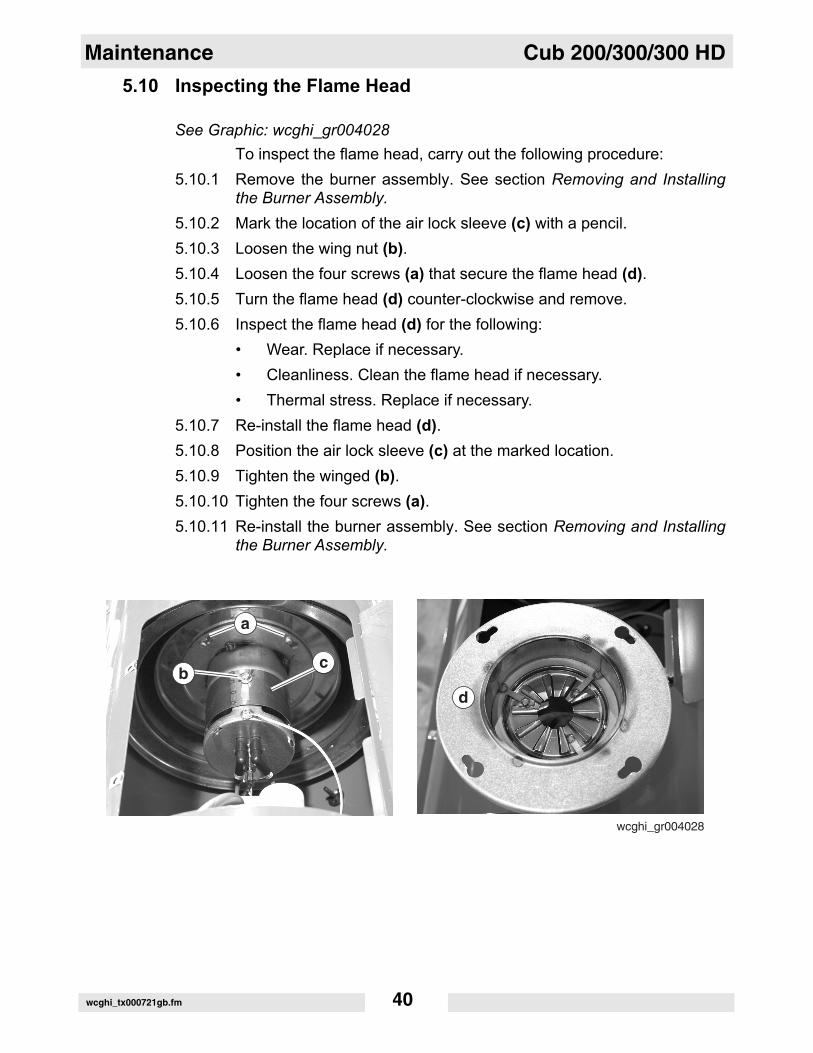
5.10 Inspecting the Flame HeadSee Graphic: wcghi_gr004028To inspect the flame head, carry out the following procedure:
5.10.1 Remove the burner assembly. See section Removing and Installingthe Burner Assembly.
5.10.2 Mark the location of the air lock sleeve (c) with a pencil.5.10.3 Loosen the wing nut (b).5.10.4 Loosen the four screws (a) that secure the flame head (d).5.10.5 Turn the flame head (d) counter-clockwise and remove.5.10.6 Inspect the flame head (d) for the following:
• Wear. Replace if necessary.• Cleanliness. Clean the flame head if necessary.• Thermal stress. Replace if necessary.
5.10.7 Re-install the flame head (d). 5.10.8 Position the air lock sleeve (c) at the marked location.5.10.9 Tighten the winged (b).5.10.10 Tighten the four screws (a).5.10.11 Re-install the burner assembly. See section Removing and Installing
the Burner Assembly.
wcghi_tx000721gb.fm 40
Cub 200/300/300 HD Maintenance
5.11 Inspecting the Electrical ConnectionsAfter disconnecting the power cord, check all electrical connections forthe following:
• Proper connections. Be sure that all connections are complete and tight.
• Corrosion. Clean or replace if necessary.• Damaged wires/connectors. Replace if necessary.• Proper ground.
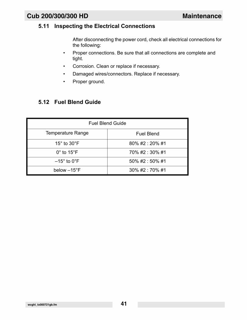
5.12 Fuel Blend Guide
Fuel Blend Guide
Temperature Range Fuel Blend
15° to 30°F 80% #2 : 20% #1
0° to 15°F 70% #2 : 30% #1
–15° to 0°F 50% #2 : 50% #1
below –15°F 30% #2 : 70% #1
wcghi_tx000721gb.fm 41
Maintenance Cub 200/300/300 HD
5.13 TransportingCub series Air Heater machines must be supported by use of blocksduring transport. NOTICE: DO NOT strap or chain down the unit withthe foot or wheels in contact with the transporter.• Openings or the entire unit should be covered during transport to
avoid road debris and clutter. • Take care when placing straps on areas which are painted red.
Use corner protectors and never use chains.• Excessive loading on the foot, wheels, and axle will cause
permanent damage• The foot and wheels are for moving by hand and for parking only.• This unit is not designed to be towed with any vehicle.• All venting external to the machine must be removed prior to
transporting. • Only qualified riggers should attempt aerial lifting.
wcghi_tx000721gb.fm 42
Cub 200/300/300 HD Maintenance
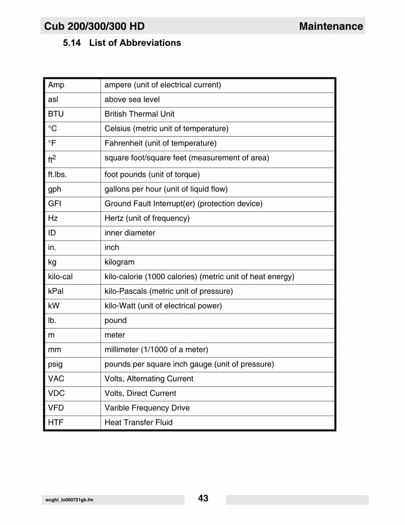
5.14 List of AbbreviationsAmp ampere (unit of electrical current)
asl above sea level
BTU British Thermal Unit
°C Celsius (metric unit of temperature)
°F Fahrenheit (unit of temperature)
ft2 square foot/square feet (measurement of area)
ft.lbs. foot pounds (unit of torque)
gph gallons per hour (unit of liquid flow)
GFI Ground Fault Interrupt(er) (protection device)
Hz Hertz (unit of frequency)
ID inner diameter
in. inch
kg kilogram
kilo-cal kilo-calorie (1000 calories) (metric unit of heat energy)
kPal kilo-Pascals (metric unit of pressure)
kW kilo-Watt (unit of electrical power)
lb. pound
m meter
mm millimeter (1/1000 of a meter)
psig pounds per square inch gauge (unit of pressure)
VAC Volts, Alternating Current
VDC Volts, Direct Current
VFD Varible Frequency Drive
HTF Heat Transfer Fluid
wcghi_tx000721gb.fm 43
Maintenance Cub 200/300/300 HD
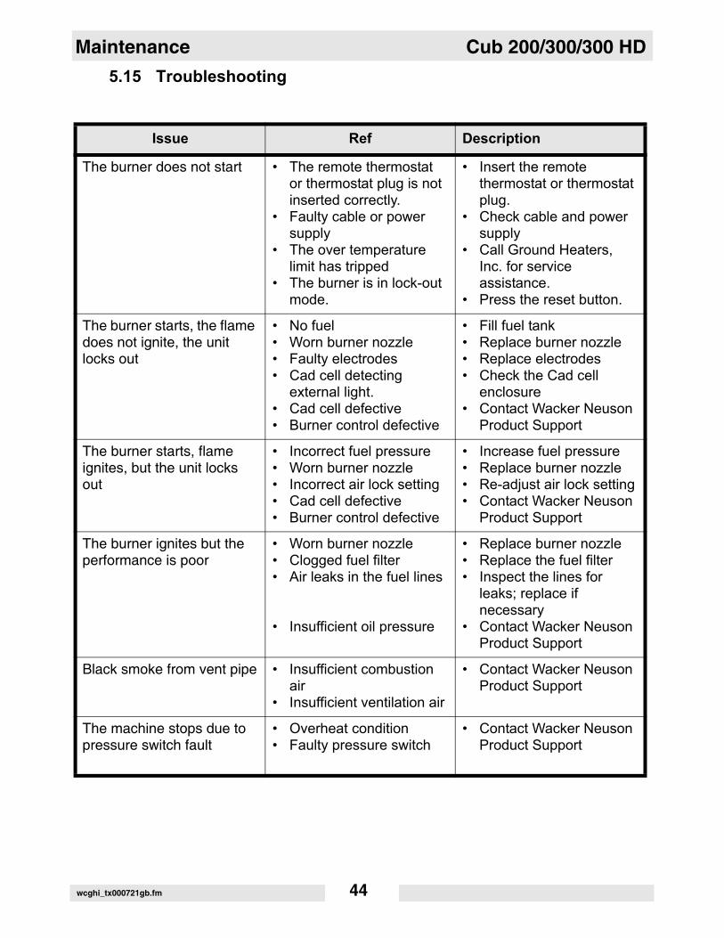
5.15 TroubleshootingIssue Ref Description
The burner does not start • The remote thermostat or thermostat plug is not inserted correctly.
• Faulty cable or power supply
• The over temperature limit has tripped
• The burner is in lock-out mode.
• Insert the remote thermostat or thermostat plug.
• Check cable and power supply
• Call Ground Heaters, Inc. for service assistance.
• Press the reset button.
The burner starts, the flame does not ignite, the unit locks out
• No fuel• Worn burner nozzle• Faulty electrodes• Cad cell detecting
external light.• Cad cell defective• Burner control defective
• Fill fuel tank• Replace burner nozzle• Replace electrodes• Check the Cad cell
enclosure• Contact Wacker Neuson
Product Support
The burner starts, flame ignites, but the unit locks out
• Incorrect fuel pressure• Worn burner nozzle• Incorrect air lock setting• Cad cell defective• Burner control defective
• Increase fuel pressure• Replace burner nozzle• Re-adjust air lock setting• Contact Wacker Neuson
Product Support
The burner ignites but the performance is poor
• Worn burner nozzle• Clogged fuel filter• Air leaks in the fuel lines
• Insufficient oil pressure
• Replace burner nozzle• Replace the fuel filter• Inspect the lines for
leaks; replace if necessary
• Contact Wacker Neuson Product Support
Black smoke from vent pipe • Insufficient combustion air
• Insufficient ventilation air
• Contact Wacker Neuson Product Support
The machine stops due to pressure switch fault
• Overheat condition• Faulty pressure switch
• Contact Wacker Neuson Product Support
wcghi_tx000721gb.fm 44

Cub 200/300/300 HD Maintenance
Notes:wcghi_tx000721gb.fm 45
Maintenance Cub 200/300/300 HD
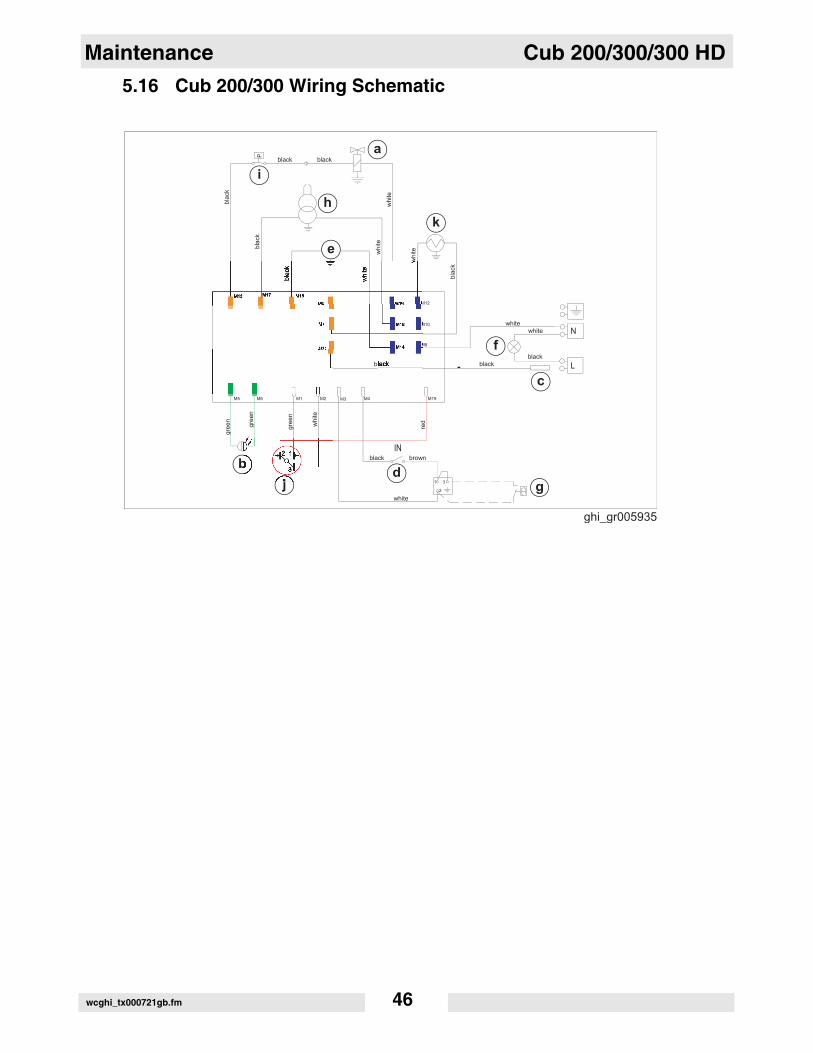
5.16 Cub 200/300 Wiring Schematicwcghi_tx000721gb.fm 46

Cub 200/300/300 HD Maintenance
5.17 Cub 300 HD Wiring Schematic5.18 Schematic Legend
Ref. Description
a Oil solenoid valve
b Photo cell
c Fuse
d Switch
e Motor
f Power light
g Remote thermostat
h Transformer
i Pressure switch
j Push button reset light
k Heated filter
l Relay
m Temperature limit control
wcghi_tx000721gb.fm 47

Maintenance Cub 200/300/300 HD
wcghi_tx000721gb.fm 48


Wacker Neuson SE · Preußenstraße 41 · D-80809 München · Tel.: +49-(0)89-3 54 02 - 0 · Fax: +49 - (0)89-3 54 02-3 90Wacker Neuson Corporation · P.O. Box 9007 · Menomonee Falls, WI 53052-9007 · Tel. : (262) 255-0500 · Fax: (262) 255-0550 · Tel. : (800) 770-0957Wacker Asia Pacific Operations · Skyline Tower, Suite 2303, 23/F · 39 Wang Kwong Road, Kowloon Bay, Hong Kong · Tel. +852 2406 60 32 · Fax: +852 2406 60 21