individual overcurrent protection · overcurrent protection provided in panelboard overcurrent...
TRANSCRIPT
31
Individual Overcurrent Protection
The National Electrical Code® requires panelboards to be individually protected against overcurrent. Main overcurrent protection may be an integral part of a panelboard or located remote from the panelboard. NEC® Article 408.36 states that each lighting and appliance branch-circuit panelboard shall be individually protected on the supply side by not more than two main circuit breakers or two sets of fuses having a combined rating not greater than that of the panelboard.
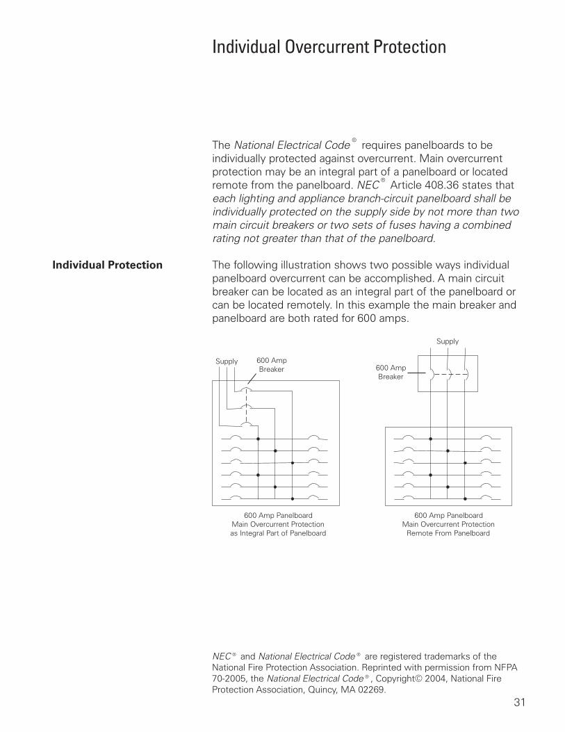
Individual Protection The following illustration shows two possible ways individual panelboard overcurrent can be accomplished. A main circuit breaker can be located as an integral part of the panelboard or can be located remotely. In this example the main breaker and panelboard are both rated for 600 amps.
Supply
Supply
600 AmpBreaker 600 Amp
Breaker
600 Amp PanelboardMain Overcurrent Protectionas Integral Part of Panelboard
600 Amp PanelboardMain Overcurrent Protection
Remote From Panelboard
NEC® and National Electrical Code® are registered trademarks of the National Fire Protection Association. Reprinted with permission from NFPA 70-2005, the National Electrical Code®, Copyright© 2004, National Fire Protection Association, Quincy, MA 02269.
32
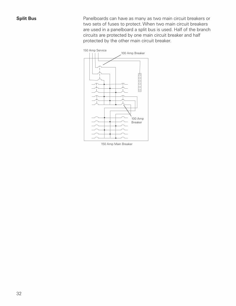
Split Bus Panelboards can have as many as two main circuit breakers or two sets of fuses to protect. When two main circuit breakers are used in a panelboard a split bus is used. Half of the branch circuits are protected by one main circuit breaker and half protected by the other main circuit breaker.
150 Amp Service100 Amp Breaker
100 Amp Breaker
150 Amp Main Breaker
33
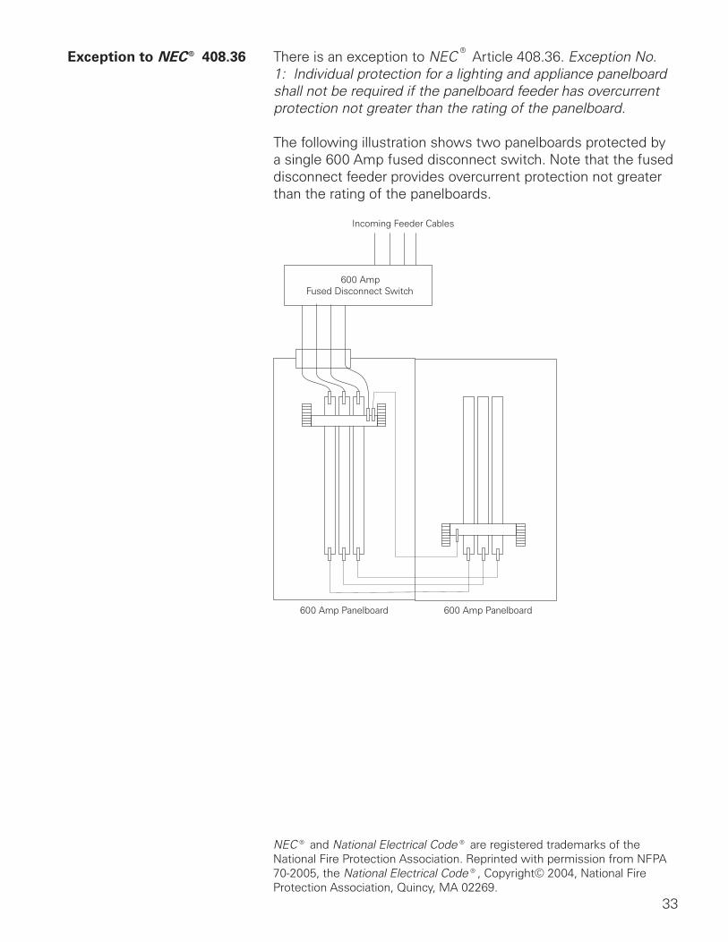
Exception to NEC® 408.36 There is an exception to NEC® Article 408.36. Exception No. 1: Individual protection for a lighting and appliance panelboard shall not be required if the panelboard feeder has overcurrent protection not greater than the rating of the panelboard.
The following illustration shows two panelboards protected by a single 600 Amp fused disconnect switch. Note that the fused disconnect feeder provides overcurrent protection not greater than the rating of the panelboards.
600 AmpFused Disconnect Switch
Incoming Feeder Cables
600 Amp Panelboard 600 Amp Panelboard
NEC® and National Electrical Code® are registered trademarks of the National Fire Protection Association. Reprinted with permission from NFPA 70-2005, the National Electrical Code®, Copyright© 2004, National Fire Protection Association, Quincy, MA 02269.
34
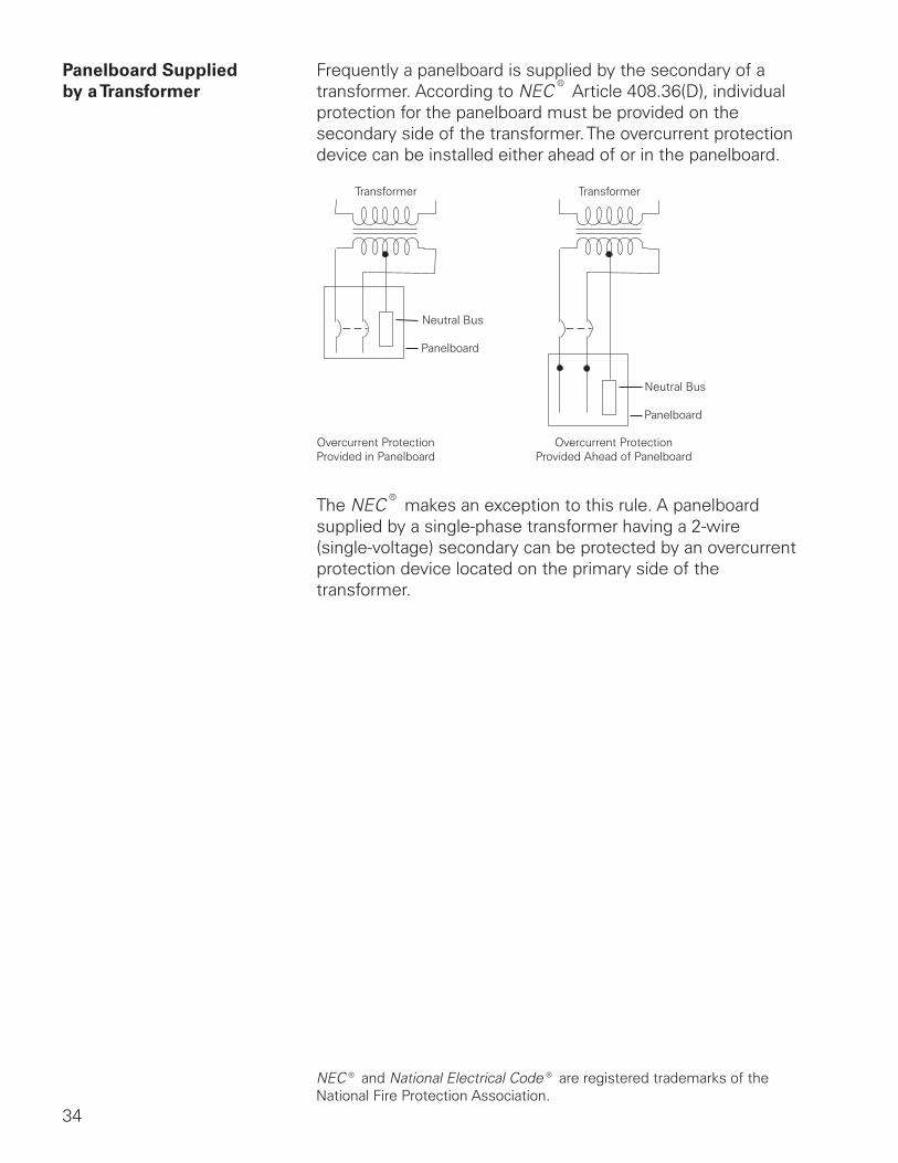
Panelboard Supplied Frequently a panelboard is supplied by the secondary of a by a Transformer transformer. According to NEC® Article 408.36(D), individual
protection for the panelboard must be provided on the secondary side of the transformer. The overcurrent protection device can be installed either ahead of or in the panelboard.
Transformer Transformer
Neutral Bus
Neutral Bus
Panelboard
Panelboard
Overcurrent ProtectionProvided in Panelboard
Overcurrent ProtectionProvided Ahead of Panelboard
The NEC® makes an exception to this rule. A panelboard supplied by a single-phase transformer having a 2-wire (single-voltage) secondary can be protected by an overcurrent protection device located on the primary side of the transformer.
NEC® and National Electrical Code® are registered trademarks of the National Fire Protection Association.
35
Review 3 1. The two types of panelboards are main ____________
and main ____________ only.
2. The main breaker of a main breaker panel can be mounted ____________ or ____________ .
3. Primary overload protection for a main ____________ type panelboard is not provided as an integral part of the panelboard.
4. ____________ - ____________ lugs are used to connect a main breaker and main lug only panelboard when they are mounted adjacent to each other.
5. The NEC® article that covers individual overcurrent protection for panelboards is ____________ .
6. A lighting and appliance branch-circuit panelboard can have as many as ____________ main circuit breakers or sets of fuses to protect it.
36
Power Supply Systems
Panelboards receive power from a variety of sources. Downstream panelboards may receive power from upstream panelboards or switchboards, however, power for the distribution system originates from a utility power company. Power from the power company is stepped down through transformers to be distributed in residential, commercial and industrial locations. Several systems are used. The following are some examples of systems in use that are suitable for Siemens panelboards.
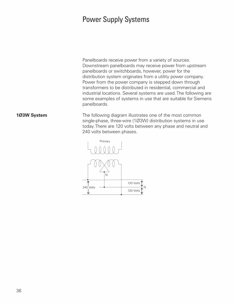
1Ø3W System The following diagram illustrates one of the most common single-phase, three-wire (1Ø3W) distribution systems in use today. There are 120 volts between any phase and neutral and 240 volts between phases.
Primary
240 Volts
N
N120 Volts
120 Volts
37
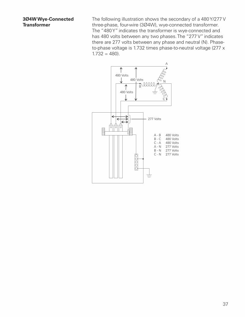
3Ø4W Wye-Connected The following illustration shows the secondary of a 480 Y/277 VTransformer three-phase, four-wire (3Ø4W), wye-connected transformer.
The “480 Y” indicates the transformer is wye-connected and has 480 volts between any two phases. The “277 V” indicates there are 277 volts between any phase and neutral (N). Phase-to-phase voltage is 1.732 times phase-to-neutral voltage (277 x 1.732 = 480).
A - BB - CC - AA - NB - NC - N
480 Volts480 Volts480 Volts277 Volts277 Volts277 Volts
277 Volts
A
B
C
N
480 Volts480 Volts
480 Volts
38
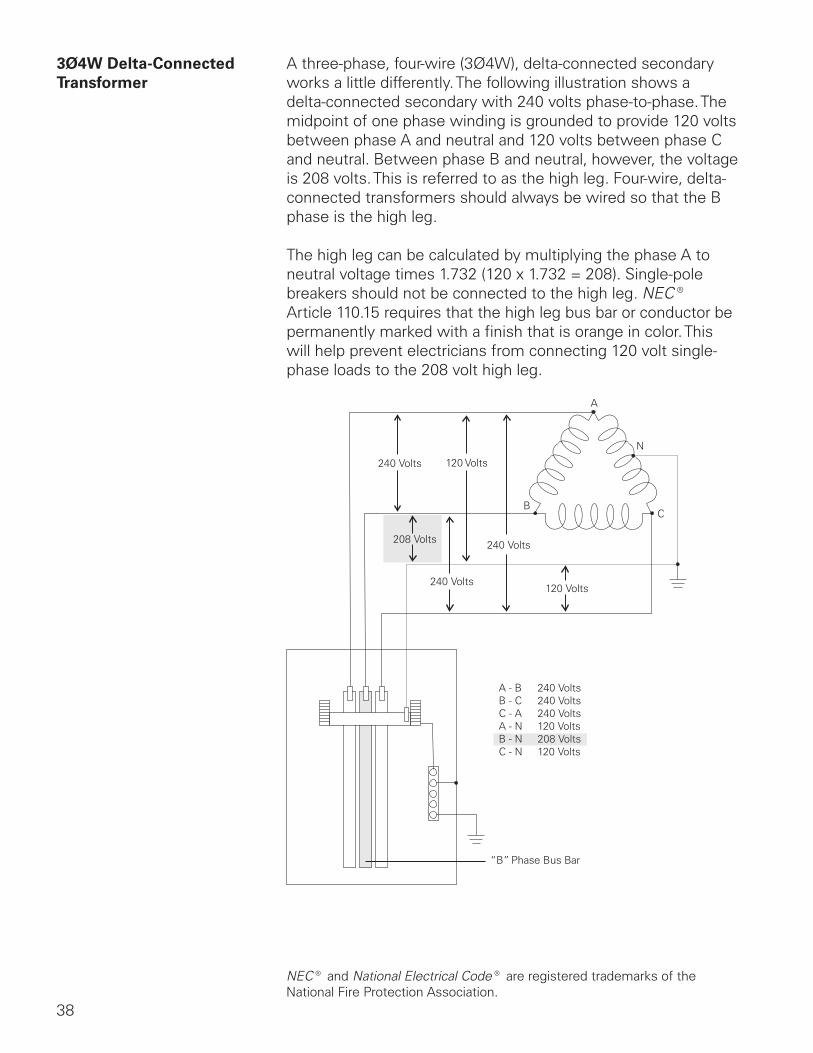
3Ø4W Delta-Connected A three-phase, four-wire (3Ø4W), delta-connected secondaryTransformer works a little differently. The following illustration shows a
delta-connected secondary with 240 volts phase-to-phase. The midpoint of one phase winding is grounded to provide 120 volts between phase A and neutral and 120 volts between phase C and neutral. Between phase B and neutral, however, the voltage is 208 volts. This is referred to as the high leg. Four-wire, delta-connected transformers should always be wired so that the B phase is the high leg.
The high leg can be calculated by multiplying the phase A to neutral voltage times 1.732 (120 x 1.732 = 208). Single-pole breakers should not be connected to the high leg. NEC® Article 110.15 requires that the high leg bus bar or conductor be permanently marked with a finish that is orange in color. This will help prevent electricians from connecting 120 volt single-phase loads to the 208 volt high leg.
A - BB - CC - AA - NB - NC - N
240 Volts240 Volts240 Volts120 Volts208 Volts120 Volts
120 Volts
240 Volts
240 Volts
240 Volts
208 Volts
A
B
N
C
“B” Phase Bus Bar
NEC® and National Electrical Code® are registered trademarks of the National Fire Protection Association.

39
Not all panelboards are suitable for use on a high leg system. Siemens P1, P2, P3, P4 and P5 panelboards are available for use on a high leg system.
Circuit Breakers on It is important to note that not all circuit breakers are suitable the High Leg for use on the high leg. For example, breakers rated for 240/120
volts can be installed on legs rated for 120 volts, but cannot be installed on the high leg (208 volts).
40
Service Entrance Panelboards
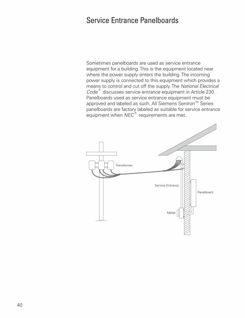
Sometimes panelboards are used as service entrance equipment for a building. This is the equipment located near where the power supply enters the building. The incoming power supply is connected to this equipment which provides a means to control and cut off the supply. The National Electrical Code® discusses service entrance equipment in Article 230. Panelboards used as service entrance equipment must be approved and labeled as such. All Siemens Sentron™ Series panelboards are factory labeled as suitable for service entrance equipment when NEC® requirements are met.
Transformer
Service Entrance
Meter
Panelboard
41
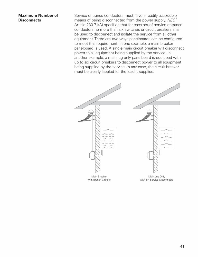
Maximum Number of Service-entrance conductors must have a readily accessible Disconnects means of being disconnected from the power supply. NEC®
Article 230.71(A) specifies that for each set of service entrance conductors no more than six switches or circuit breakers shall be used to disconnect and isolate the service from all other equipment. There are two ways panelboards can be configured to meet this requirement. In one example, a main breaker panelboard is used. A single main circuit breaker will disconnect power to all equipment being supplied by the service. In another example, a main lug only panelboard is equipped with up to six circuit breakers to disconnect power to all equipment being supplied by the service. In any case, the circuit breaker must be clearly labeled for the load it supplies.
Main Breakerwith Branch Circuits
Main Lug Onlywith Six Service Disconnects
42
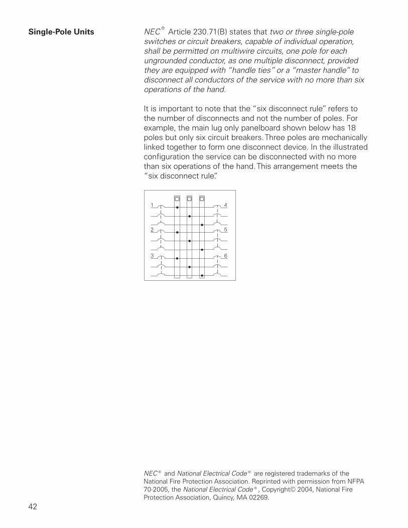
Single-Pole Units NEC® Article 230.71(B) states that two or three single-pole switches or circuit breakers, capable of individual operation, shall be permitted on multiwire circuits, one pole for each ungrounded conductor, as one multiple disconnect, provided they are equipped with “handle ties” or a “master handle” to disconnect all conductors of the service with no more than six operations of the hand.
It is important to note that the “six disconnect rule” refers to the number of disconnects and not the number of poles. For example, the main lug only panelboard shown below has 18 poles but only six circuit breakers. Three poles are mechanically linked together to form one disconnect device. In the illustrated configuration the service can be disconnected with no more than six operations of the hand. This arrangement meets the “six disconnect rule”.
NEC® and National Electrical Code® are registered trademarks of the National Fire Protection Association. Reprinted with permission from NFPA 70-2005, the National Electrical Code®, Copyright© 2004, National Fire Protection Association, Quincy, MA 02269.
43
Panelboard Grounding
Grounding is an important aspect of any electrical equipment and must be considered carefully. Article 250 of the NEC® covers mandatory grounding requirements. The National Electrical Code® defines ground as a conducting connection, whether intentional or accidental, between an electrical circuit or equipment and the earth, or to some conducting body that serves in place of the earth.
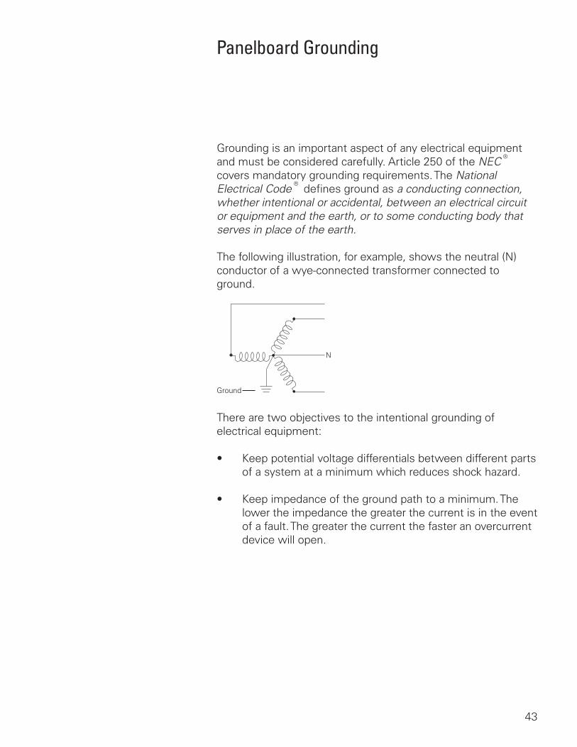
The following illustration, for example, shows the neutral (N) conductor of a wye-connected transformer connected to ground.
Ground
N
There are two objectives to the intentional grounding of electrical equipment:
• Keep potential voltage differentials between different parts of a system at a minimum which reduces shock hazard.
• Keep impedance of the ground path to a minimum. The lower the impedance the greater the current is in the event of a fault. The greater the current the faster an overcurrent device will open.
44
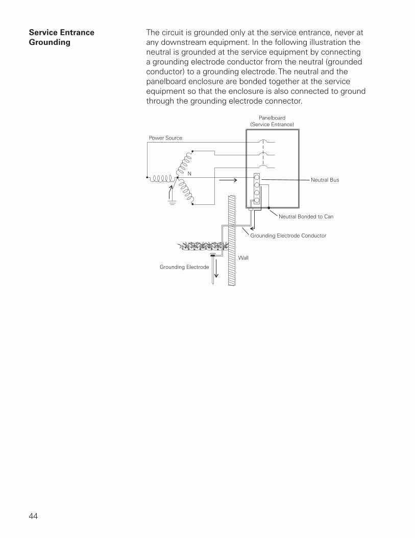
Service Entrance The circuit is grounded only at the service entrance, never at Grounding any downstream equipment. In the following illustration the
neutral is grounded at the service equipment by connecting a grounding electrode conductor from the neutral (grounded conductor) to a grounding electrode. The neutral and the panelboard enclosure are bonded together at the service equipment so that the enclosure is also connected to ground through the grounding electrode connector.
Panelboard(Service Entrance)
Neutral Bus
Neutral Bonded to Can
Grounding Electrode Conductor
Wall
Grounding Electrode
Power Source
N
45
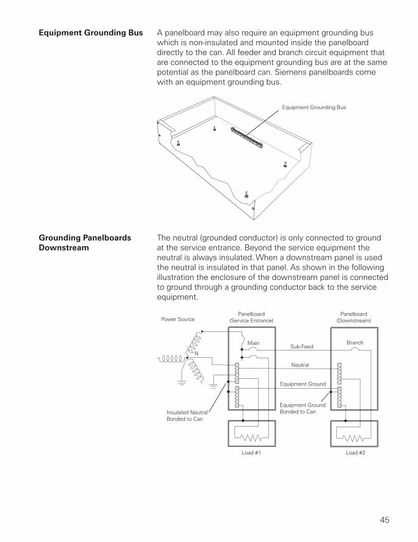
Equipment Grounding Bus A panelboard may also require an equipment grounding bus which is non-insulated and mounted inside the panelboard directly to the can. All feeder and branch circuit equipment that are connected to the equipment grounding bus are at the same potential as the panelboard can. Siemens panelboards come with an equipment grounding bus.
Equipment Grounding Bus
Grounding Panelboards The neutral (grounded conductor) is only connected to ground Downstream at the service entrance. Beyond the service equipment the
neutral is always insulated. When a downstream panel is used the neutral is insulated in that panel. As shown in the following illustration the enclosure of the downstream panel is connected to ground through a grounding conductor back to the service equipment.
Power Source
N
Insulated NeutralBonded to Can
Panelboard(Service Entrance)
Panelboard(Downstream)
Main
Load #1 Load #2
Sub-Feed
Neutral
Equipment Ground
Equipment GroundBonded to Can
Branch
46
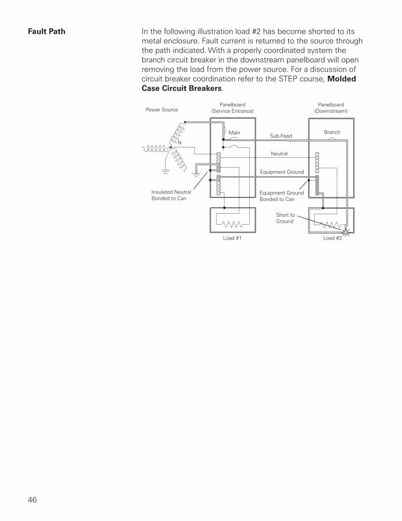
Fault Path In the following illustration load #2 has become shorted to its metal enclosure. Fault current is returned to the source through the path indicated. With a properly coordinated system the branch circuit breaker in the downstream panelboard will open removing the load from the power source. For a discussion of circuit breaker coordination refer to the STEP course, Molded Case Circuit Breakers.
Power Source
N
Insulated NeutralBonded to Can
Panelboard(Service Entrance)
Panelboard(Downstream)
Main
Load #1 Load #2
Sub-Feed
Neutral
Equipment Ground
Equipment GroundBonded to Can
Short toGround
Branch
47
Review 41. If the secondary of a four-wire, wye-connected
transformer is 480 volts phase-to-phase, the phase to neutral voltage is ____________ volts.
2. If the secondary of a four-wire, delta-connected transformer is 240 volts phase-to-phase, the phase to neutral voltage is
____________ volts from A-N
____________ volts from B-N
____________ volts from C-N
3. According to NEC® Article 230.71(A), the maximum number of circuit breakers that can be used to disconnect and isolate the service from all other equipment is ____________ .
4. ____________ is the permanent joining of metallic parts to form an electrically conductive path.
5. The ____________ conductor is grounded only at the service entrance equipment, never at any downstream equipment.
48
Ground Fault Protection
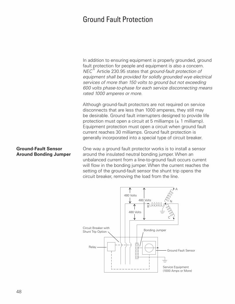
In addition to ensuring equipment is properly grounded, ground fault protection for people and equipment is also a concern. NEC® Article 230.95 states that ground-fault protection of equipment shall be provided for solidly grounded wye electrical services of more than 150 volts to ground but not exceeding 600 volts phase-to-phase for each service disconnecting means rated 1000 amperes or more.
Although ground-fault protectors are not required on service disconnects that are less than 1000 amperes, they still may be desirable. Ground fault interrupters designed to provide life protection must open a circuit at 5 milliamps (± 1 milliamp). Equipment protection must open a circuit when ground fault current reaches 30 milliamps. Ground fault protection is generally incorporated into a special type of circuit breaker.
Ground-Fault Sensor One way a ground fault protector works is to install a sensor Around Bonding Jumper around the insulated neutral bonding jumper. When an
unbalanced current from a line-to-ground fault occurs current will flow in the bonding jumper. When the current reaches the setting of the ground-fault sensor the shunt trip opens the circuit breaker, removing the load from the line.
Circuit Breaker withShunt Trip Option
Relay
Service Equipment(1000 Amps or More)
Ground Fault Sensor
Bonding Jumper
480 Volts
480 Volts
480 Volts
A
B
C
N
49
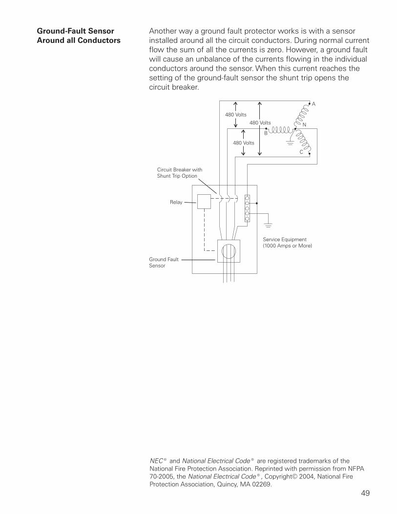
Ground-Fault Sensor Another way a ground fault protector works is with a sensor Around all Conductors installed around all the circuit conductors. During normal current
flow the sum of all the currents is zero. However, a ground fault will cause an unbalance of the currents flowing in the individual conductors around the sensor. When this current reaches the setting of the ground-fault sensor the shunt trip opens the circuit breaker.
Circuit Breaker withShunt Trip Option
Relay
Service Equipment(1000 Amps or More)
Ground Fault Sensor
480 Volts
480 Volts
480 Volts
A
B
C
N
NEC® and National Electrical Code® are registered trademarks of the National Fire Protection Association. Reprinted with permission from NFPA 70-2005, the National Electrical Code®, Copyright© 2004, National Fire Protection Association, Quincy, MA 02269.
50
Panelboard Ratings
When selecting panelboards and overcurrent protection devices it is extremely important to know both the maximum continuous amperes and available fault current. NEC® Article 110.9 states:
Equipment intended to interrupt current at fault levels shall have an interrupting rating sufficient for the nominal circuit voltage and the current which is available at the line terminals of the equipment.
Equipment intended to interrupt current at other than fault levels shall have an interrupting rating at nominal circuit voltage sufficient for the current that must be interrupted.
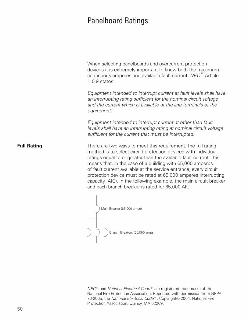
Full Rating There are two ways to meet this requirement. The full rating method is to select circuit protection devices with individual ratings equal to or greater than the available fault current. This means that, in the case of a building with 65,000 amperes of fault current available at the service entrance, every circuit protection device must be rated at 65,000 amperes interrupting capacity (AIC). In the following example, the main circuit breaker and each branch breaker is rated for 65,000 AIC.
Main Breaker (65,000 amps)
Branch Breakers (65,000 amps)
NEC® and National Electrical Code® are registered trademarks of the National Fire Protection Association. Reprinted with permission from NFPA 70-2005, the National Electrical Code®, Copyright© 2004, National Fire Protection Association, Quincy, MA 02269.
51
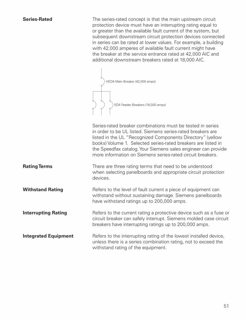
Series-Rated The series-rated concept is that the main upstream circuit protection device must have an interrupting rating equal to or greater than the available fault current of the system, but subsequent downstream circuit protection devices connected in series can be rated at lower values. For example, a building with 42,000 amperes of available fault current might have the breaker at the service entrance rated at 42,000 AIC and additional downstream breakers rated at 18,000 AIC.
HED4 Main Breaker (42,000 amps)
ED4 Feeder Breakers (18,000 amps)
Series-rated breaker combinations must be tested in series in order to be UL listed. Siemens series-rated breakers are listed in the UL “Recognized Components Directory” (yellow books) Volume 1. Selected series-rated breakers are listed in the Speedfax catalog. Your Siemens sales engineer can provide more information on Siemens series-rated circuit breakers.
Rating Terms There are three rating terms that need to be understood when selecting panelboards and appropriate circuit protection devices.
Withstand Rating Refers to the level of fault current a piece of equipment can withstand without sustaining damage. Siemens panelboards have withstand ratings up to 200,000 amps.
Interrupting Rating Refers to the current rating a protective device such as a fuse or circuit breaker can safely interrupt. Siemens molded case circuit breakers have interrupting ratings up to 200,000 amps.
Integrated Equipment Refers to the interrupting rating of the lowest installed device, unless there is a series combination rating, not to exceed the withstand rating of the equipment.
52
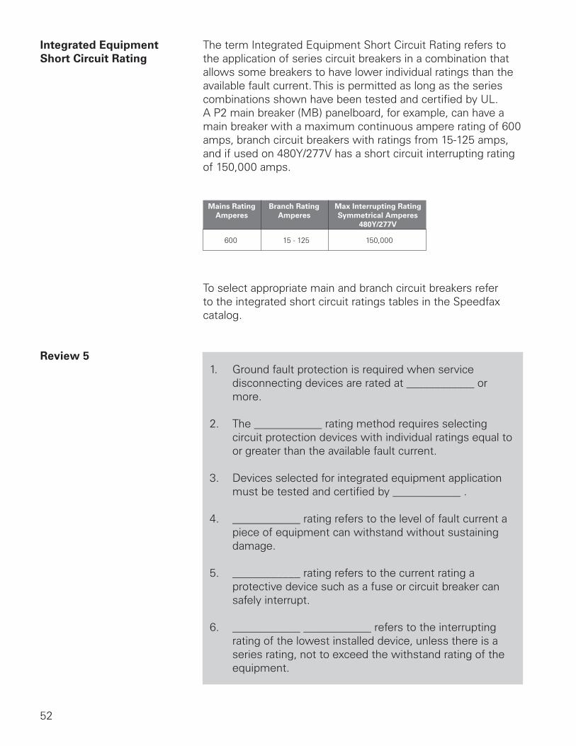
Integrated Equipment The term Integrated Equipment Short Circuit Rating refers to Short Circuit Rating the application of series circuit breakers in a combination that
allows some breakers to have lower individual ratings than the available fault current. This is permitted as long as the series combinations shown have been tested and certified by UL. A P2 main breaker (MB) panelboard, for example, can have a main breaker with a maximum continuous ampere rating of 600 amps, branch circuit breakers with ratings from 15-125 amps, and if used on 480Y/277V has a short circuit interrupting rating of 150,000 amps.
600 15 - 125 150,000
Mains RatingAmperes
Branch RatingAmperes
Max Interrupting RatingSymmetrical Amperes
480Y/277V
To select appropriate main and branch circuit breakers refer to the integrated short circuit ratings tables in the Speedfax catalog.
Review 51. Ground fault protection is required when service
disconnecting devices are rated at ____________ or more.
2. The ____________ rating method requires selecting circuit protection devices with individual ratings equal to or greater than the available fault current.
3. Devices selected for integrated equipment application must be tested and certified by ____________ .
4. ____________ rating refers to the level of fault current a piece of equipment can withstand without sustaining damage.
5. ____________ rating refers to the current rating a protective device such as a fuse or circuit breaker can safely interrupt.
6. ____________ ____________ refers to the interrupting rating of the lowest installed device, unless there is a series rating, not to exceed the withstand rating of the equipment.
53
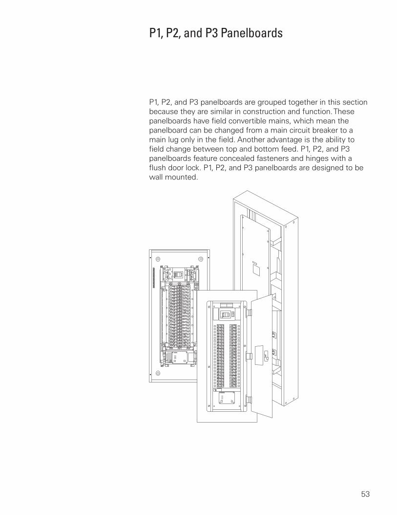
P1, P2, and P3 Panelboards
P1, P2, and P3 panelboards are grouped together in this section because they are similar in construction and function. These panelboards have field convertible mains, which mean the panelboard can be changed from a main circuit breaker to a main lug only in the field. Another advantage is the ability to field change between top and bottom feed. P1, P2, and P3 panelboards feature concealed fasteners and hinges with a flush door lock. P1, P2, and P3 panelboards are designed to be wall mounted.
54
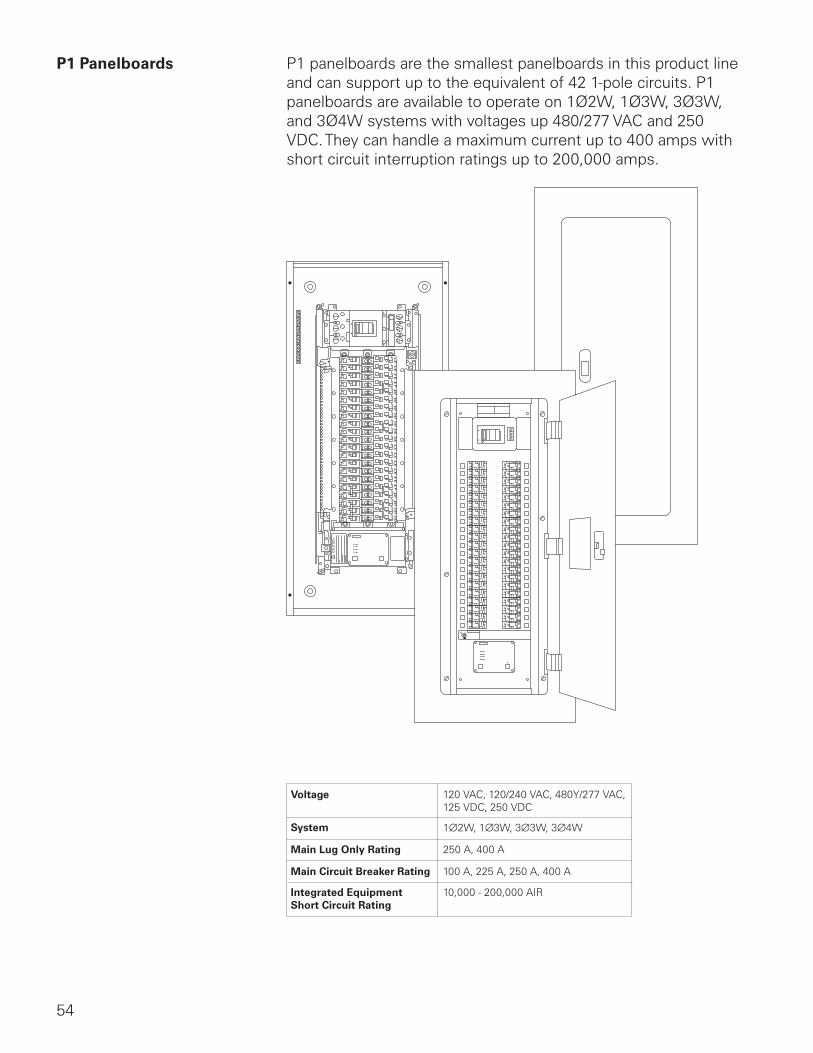
P1 Panelboards P1 panelboards are the smallest panelboards in this product line and can support up to the equivalent of 42 1-pole circuits. P1 panelboards are available to operate on 1Ø2W, 1Ø3W, 3Ø3W, and 3Ø4W systems with voltages up 480/277 VAC and 250 VDC. They can handle a maximum current up to 400 amps with short circuit interruption ratings up to 200,000 amps.
Voltage
System
Main Lug Only Rating
Main Circuit Breaker Rating
Integrated EquipmentShort Circuit Rating
120 VAC, 120/240 VAC, 480Y/277 VAC,125 VDC, 250 VDC
1∅2W, 1∅3W, 3∅3W, 3∅4W
250 A, 400 A
100 A, 225 A, 250 A, 400 A
10,000 - 200,000 AIR
55
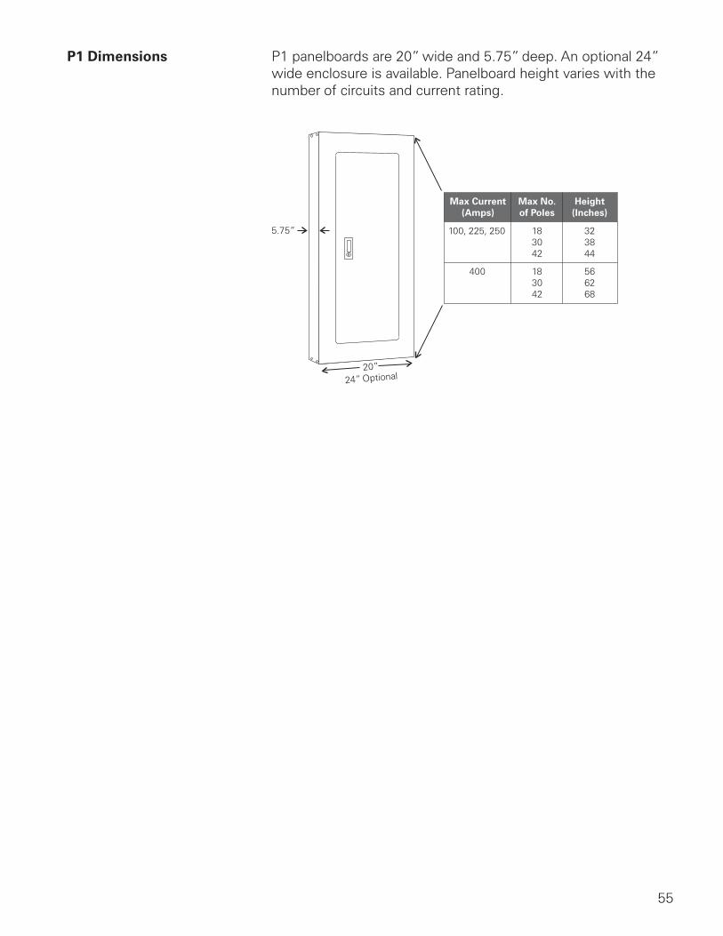
P1 Dimensions P1 panelboards are 20” wide and 5.75” deep. An optional 24” wide enclosure is available. Panelboard height varies with the number of circuits and current rating.
5.75”
20”
24” Optional
Max Current(Amps)
Max No.of Poles
Height(Inches)
100, 225, 250
400
183042
183042
323844
566268
56
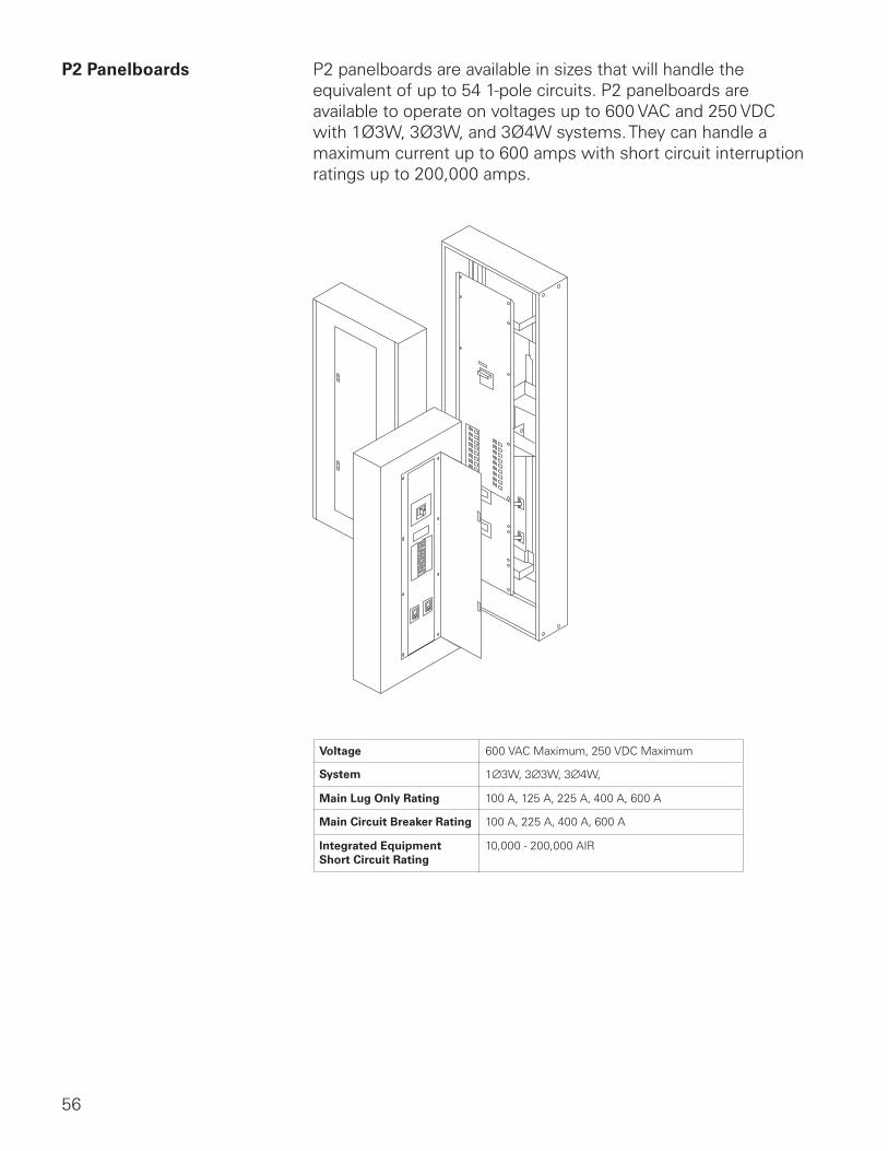
P2 Panelboards P2 panelboards are available in sizes that will handle the equivalent of up to 54 1-pole circuits. P2 panelboards are available to operate on voltages up to 600 VAC and 250 VDC with 1Ø3W, 3Ø3W, and 3Ø4W systems. They can handle a maximum current up to 600 amps with short circuit interruption ratings up to 200,000 amps.
Voltage
System
Main Lug Only Rating
Main Circuit Breaker Rating
Integrated EquipmentShort Circuit Rating
600 VAC Maximum, 250 VDC Maximum
100 A, 125 A, 225 A, 400 A, 600 A
100 A, 225 A, 400 A, 600 A
10,000 - 200,000 AIR
1∅3W, 3∅3W, 3∅4W,
57
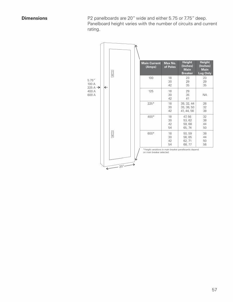
Dimensions P2 panelboards are 20” wide and either 5.75 or 7.75” deep. Panelboard height varies with the number of circuits and current rating.
5.75”100 A225 A400 A600 A
20”
Main Current(Amps)
Max No.of Poles
Height(Inches)
MainBreaker
Height(Inches)
MainLug Only
100
125
225*
400*
600*
183042
183042
183042
18304254
18304254
232935
232935
293541
39, 32, 4435, 38, 5041, 44, 56
47, 5653, 6259, 6865, 74
50, 5956, 6562, 7168, 77
NA
263238
32384450
38445056
*Height variations in main breaker panelboards depend on main breaker selected
58
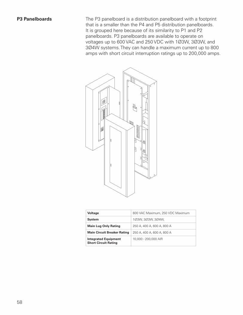
P3 Panelboards The P3 panelboard is a distribution panelboard with a footprint that is a smaller than the P4 and P5 distribution panelboards. It is grouped here because of its similarity to P1 and P2 panelboards. P3 panelboards are available to operate on voltages up to 600 VAC and 250 VDC with 1Ø3W, 3Ø3W, and 3Ø4W systems. They can handle a maximum current up to 800 amps with short circuit interruption ratings up to 200,000 amps.
Voltage
System
Main Lug Only Rating
Main Circuit Breaker Rating
Integrated EquipmentShort Circuit Rating
600 VAC Maximum, 250 VDC Maximum
250 A, 400 A, 600 A, 800 A
250 A, 400 A, 600 A, 800 A
10,000 - 200,000 AIR
1∅3W, 3∅3W, 3∅4W,