indoor positioning system based on the ultra wide...
TRANSCRIPT

1. Introduction
Outdoor positioning can be improved with the start-up of Galileo. So, the accuracy willusually be in the order of a few metres. With Galileo services, the users needs requirethe same performances in outdoor and indoor applications. This is more obviously true inthe construction, hypermarket, museums, where location awareness can become a crucialparameter for value-added services, especially for Galileo-GPS services. Positioning indifficult environments, especially in indoor, represents a current limitation for localisationsystems (GPS/Galileo). In fact, indoor positioning faces additional difficulties as compared tooutdoor positioning. Attenuation and multipath reflections of the line-of-sight (LOS) signal(or direct path) by the walls, floors, and ceiling of a tunnel are the main factors preventingtypical GPS receivers from functioning indoors. Most of the time, the sum of multipathsignals is stronger than the direct path signal, thereby preventing the receiver from accuratelycalculating the time of arrival [1]. The multipath signal distorts the cross correlation functionpeak, as detected by a receiver. The scientific and industrial community, especially in transportapplications, considers that it is important to provide a positioning function in indoor (tunnel,station...) with a good performance of about a few centimetre. So, in order to reach thisperformance level, different techniques are under development, such as Ultra Wide Bandtechnology. The UWB promises to overcome the power consumption and accuracy limitationsof both the GPS and WLAN, and is more suitable for indoor location-based applications. Infact, Ultra Wide Band (UWB) technology provides high accuracy positioning in the multipathand confined environments typically found inside buildings. Integration of UWB with GPS orGalileo can provide a seamless transition from outdoor to indoor position and vice-versa.The ranging accuracy expected from UWB systems should be better than 0.5m in severemultipath environments [2, 3]. This chapter focuses on the indoor positioning system usingthe Ultra Wide Band, especially for transport applications. The first section is dedicated tointroducing the indoor positioning application [3]. After this introduction, we present a briefreview of some relevant work [7–9]. In indoor positioning system especially for transportapplications two scenarios are considered: the self localisation and server-based localisation
©2012 Elbahhar et al., licensee InTech. This is an open access chapter distributed under the terms of theCreative Commons Attribution License (http://creativecommons.org/licenses/by/3.0),which permitsunrestricted use, distribution, and reproduction in any medium, provided the original work is properlycited.
Indoor Positioning System Based on the Ultra Wide Band for Transport Applications
F. Elbahhar, B. Fall, A. Rivenq, M. Heddebaut and R. Elassali
Additional information is available at the end of the chapter
http://dx.doi.org/10.5772/50017
Chapter 4

2 Positioning Systems
([4–6]). In the self localisation, called the positioning system, the mobile receives signals fromthe bases station (the transmitter) and interprets the received-signals as ambient informationfor localising its position in a local coordinate system. The server-based localisation (fixedpoints) is based on the measure of the signals radiated from a mobile. Then, using thesignals measured at distributed sensors, the server estimates the position of the mobile. Inthe second section of this chapter, we present two approaches for UWB positioning. Thefirst one is based on the Direct Sequence Spread Spectrum UWB technique. The secondone is based on the new waveforms, using the orthogonal waveforms, called the ModifiedGegenbauer Functions. These functions allow specific waveforms for each transmitter witha good orthogonal propriety [3]. Theses approaches are studied and evaluated in terms oflocalisation errors for different multipath channels. The multipath channel effect in the UWBenvironment is introduced and analysed in this section for indoor positioning applications.In the third section, the test results using laboratory instruments are presented to validate thesimulation and analytical results, given in the second section. In the fourth section, the firstresults concerning a new positioning approach for railway application, using UWB radio andTime Reversal techniques, are given. The last section of this chapter is dedicated to proposingconclusions and recommendations for future research.
2. Introduction of the indoor positioning system
In indoor positioning system two scenarios are considered: the self localisation andserver-based localisation. In the self localisation, the mobile receives signals from the BaseStations BS (the transmitter) and interprets the received-signals as ambient information forlocalising its position in a local coordinate system. The block schema of this scenario isillustrated in figure 1. Each station (access point) sends the radio frequency signal and theprocessing, used to calculate of the mobile position, is realised in the mobile. The server-basedlocalisation (fixed points) is based on the measure of the signals radiated from a mobile. Then,using the signals measured at distributed sensors, the server estimates the position of themobile. The block schema of the second scenario is illustrated in figure 2.
Figure 1. The self localisation: the positioning system approach.
Positioning techniques exploit one or more characteristics of radio signals to estimate theposition of their source or the self position. Depending on accuracy requirements andconstraints on transceiver design, various signal parameters can be employed. Commonly, asingle parameter is estimated for each received signal. However, it is also possible to estimatemultiple signal parameters in order to improve positioning accuracy. Some of the parametersthat have been used for positioning are the Received Signal Strength Intensity (RSSI), the
70 New Approach of Indoor and Outdoor Localization Systems

Indoor Positioning System Based onthe Ultra Wide Band for Transport Applications 3
Figure 2. The server-based localisation approach.
Angle Of Arrival (AOA), the Time Of Arrival (TOA) and the Difference of Time Of Arrival(TDOA).
• Received Signal Strength Intensity (RSSI): provides information about the distancebetween two points. The main idea behind the RSS approach is that if the relation betweendistance and power loss is known, the RSS measurement at a point can be used to estimatethe distance between that point and the transmitting point, assuming that the transmittedpower is known.
• The Angle Of Arrival (AOA): this technique is based on determining the direction of thearrival signal. A stationary device measures the angle of arrival of the signal sent by amobile device. Location can be estimated through triangulation if at least two stationarydevices perform measurement. Measuring angles requires a specific antenna array. Theangle information is obtained at an antenna array by measuring the difference in arrivaltimes of an incoming signal at different antenna elements.
• Time Of Arrival (TOA): In TOA positioning, a mobile device sends a signal to a stationarydevice, which sends it back to the mobile device. The mobile device measures theround-trip time (RTT) of the signal. This leads to a circle, whose radius corresponds tohalf of the RTT and whose centre is on the location of the stationary device. Location ofthe mobile device can be approximated to be at the intersection of at least three measuredcircles. This technique requires accurate clocks because a 1μsec error in timing equals to a300 m error in distance estimate. Thus, the accuracy is too low for TOA positioning.
• Time Difference Of Arrival (TDOA): TDOA positioning is developed to eliminate thetight synchronization requirement of TOA. In fact TOA range measurements requiresynchronisation among the mobile station (MS) and the Base Station BS (transmitter).However, TDOA measurement can be obtained even in the absence of synchronisationbetween MS and BS, if there is synchronisation among the base stations. In this case, thedifference between the arrival time of two signals travelling between the MS and BS isestimated. This locates the MS on a hyperbola with foci at the BS.
Instead of performing a single measurement such as RSSI, AOA or TOA, a point can beestimated using a combination of position-related parameters. Such hybrid approaches canprovide more accurate information about the position of the mobile than the approachesthat estimate a single position parameter. Various combinations on measurement, such asTOA/AOA, TDOA/AOA and TOA/RSSI, are possible depending on accuracy requirement,complexity constraints, propagation environment and necessary processing delay [13, 18].
71Indoor Positioning System Based on the Ultra Wide Band for Transport Applications

4 Positioning Systems
3. Indoor positioning application
Indoor localisation is the determination of the position of a device or a person in an indoorenvironment. While the localisation in outdoor environments can in most cases, efficientlyand accurately use the GPS, or some more accurate variants like D-GPS, these systems areusually not efficient indoors. Typically, the transit satellite signal is highly damped whentraversing the building and is not sufficient for a receiver to be detected. Satellite signals whichare reflected by surrounding buildings may be detected through windows, but the path lengthfor the satellites will be altered differently each from another and the position determinationwill be inaccurate to some 10..1000 meters.Therefore, the investigation of position detectiontechnologies suitable for indoor environments is a current research and development topic.
3.1. Large public indoor positioning application
In recent years the applications for indoor localisation information have been developed andtheir use has increased. The new technologies continue to improve with better and moreaccurate positioning information. So, the new applications have been developed for the massconsumer markets. Different indoor location services and applications are offered in variousdomains. Location-based advertising has an application in a scenario in which the cell phoneof a visitor to a mall can be located and used to display an advertisement of a shop very nearto where its holder is located. Person and asset tracking applications in schools: surveillanceof the children, criminals can be monitored using the positioning system, items can be trackedin warehouses, materials and equipment in manufacturing areas.
3.2. Indoor positioning application for transport applications
For transport applications, especially in subway transportation areas, it is very important toensure the positioning service. In fact, the subway line is divided in parts called sectionsof about 500 m in length. When a train is in a section, it is declared to be engaged and nocoach can go in until the train leaves it. This is the safety system adopted in most of thecurrent networks. In this scope, only a few trains (say from 2 to 4, due to limited emittedpower) will be allowed to receive or transmit data or video in any given area, includingmessages broadcast to passengers or security information sent to or from the control center,such as train status or problems encountered on the track or onboard. For this application, thedistance between a train and a preceding one must be known to a precision in the sub-meterrange over distances higher than one hundred meters in the train location application. So,for this application, it is important to use the positioning system able to operate with goodperformance in terms of the precision, positioning error and the processing delays. Anotherexample can be cited concerning the public transport. In fact, knowing the position of our trainor bus allows us to have pertinent information such as the lists of closest hotels, spectales andrestuarants.These examples demonstrate that localisation may be needed as a key componentfor numerous domains.
3.3. Existing technical solutions for indoor positioning
Several techniques and commercial systems are used for indoor localisation. For exemple, aWLAN-based system is used to calculate positions by measuring the received signal strength(RSS). RADAR [16] (Microsoft) and Place Lab (Intel) are WLAN-based positioning systems.
72 New Approach of Indoor and Outdoor Localization Systems

Indoor Positioning System Based onthe Ultra Wide Band for Transport Applications 5
The infrared-based method is used with the sensors that recognize the unique ID codes ofinfrared devices. Although the structure of this system is simple and the cost is low, a limitedvisibility range and line-of-sight (LOS) obstructions are its weak points. Ultrasonic-basedsystem uses the difference in the transfer speed between RF and ultrasonic signals. Thissystem has the advantages of 3D position recognition, low-power, and low cost. The Cricketsystem (MIT) and the Active bat system (AT&T Lab) [17] both use ultrasonic technology.Another radio frequency technique identification RFID system utilises a tag-and-readerscheme. Such tags contain circuitry that gain power from radio waves emitted by readers intheir vicinity. They use this power to reply their unique identifier to the reader. This techniqueis very attractive because of the reasonable system price, and reader reliability but the majordisadvantage of this technique is the very limited range, lower than 10m.
Using current generation non-dedicated narrow band WLAN/WPAN derived technologies,a few meter localisation accuracy is achievable in indoor environments. However, this levelof performance appears insufficient for some specific applications and services for exampletransport applications. These applications usually necessitate high performance in termsof precision and processing delay. The UWB technique is an excellent signalling choice forhigh accuracy localisation in short to medium distance, due to its high time resolution andinexpensive circuit.
Commonly, a UWB signal is defined to be a signal with a fractional bandwidth B f r of morethan 20% or an absolute bandwidth B of at least 500 MHz. The absolute bandwidth iscalculated as the difference between the upper frequency fh and the lower frequency fl ofthe -10 dB emission point (equation 1).
B = fh − fl (1)
The fractional bandwidth is defined as:
B f r =Bfc
(2)
where fc is the center frequency ans is given by equation 3:
fc =fh + fl
2(3)
Due to their large bandwidth, UWB signal is characterized by very short duration waveforms.A UWB system transmits ultra short pulses with a low duty cycle. So, the ratio betweenthe pulse transmission instant and the average time between two consecutive transmissionsis usually kept small. There are two competing technologies for the UWB Wirelesscommunication systems, namely: Impulse Radio (IR) and Multi-band OFDM (MB-OFDM).The IR-UWB technique is based on the transmission of very short pulses with relatively lowenergy. The IR-UWB provides lower data rates (a few Mbits/s) at higher ranges (tens ofmeters) with the possibility to have the positioning function. The MB-OFDM system givespotentially very high rates (in the order of 500 Mbits/s) with very short ranges (a few meters),the very wide frequency band used being divided into 14 sub-bands (500 MHz each). Severalproposals based on these two technologies have been submitted to the IEEE 802.15 [19]. Bothtechnologies are valid and credible. In addition to high rate Wireless communication systems,UWB signals have also been considered for low rate Wireless communication that focus on
73Indoor Positioning System Based on the Ultra Wide Band for Transport Applications

6 Positioning Systems
low power and low complexity devices. The IEEE formed the task group 4a standard foralternative PHY. The IEEE 802.15.4a provides high precision ranging /positioning and ultrapower consumption. This standard is considered in this chapter. Two positioning systems arestudied, DS-CDMA/UWB, and an original solution based on the orthogonal waveforms, andcompared in terms of positioning errors.
4. The UWB proposed positioning system
4.1. The UWB waveforms
Some common UWB waveforms include Gaussian, monocycle pulse; pulse based on themodified Hermite polynomials. For example, the Gaussian and monocycle pulses (figure 3),given, respectively, the equation 4:
w(t) = exp(− t
τ
)2
v(t) = tτ exp
(− tτ
)2 (4)
with τ the pulse duration.
Figure 3. Time representation of Gaussian and the monocycle waveforms.
Other waveforms based on the orthogonal polynomial especially the Gegenbauerpolynomials, can be used. These functions allow us to modulate the data and, simultaneously,guarantee the multi-user system [20]. Indeed, in the indoor localisation system thetransmitters share the channel propagation. So, it is necessary to use a multiple accesstechnique based on the orthogonal codes (for example: Gold code) or the orthogonalpolynomials.
The MGF Gn(β, x) uses the weight function W(x) = (1− x2)β−1/2 where β > −1/2 is a shapeparameter, n is the degree of the function and x is the variable. These functions are orthogonalon the interval [−1, 1] for m �= n:
1∫−1
w(x)Gn(β, x)Gm(β, x)dx = 0 (5)
These functions can be defined by a recurrence relation. Furthermore, they satisfy thedifferential equation 6.
Gn(β, x) = 2n + β− 1
nxGn−1(β, x)− n + 2β− 2
nGn−2(β, x) (6)
74 New Approach of Indoor and Outdoor Localization Systems

Indoor Positioning System Based onthe Ultra Wide Band for Transport Applications 7
Their expressions for the first few orders are given by the following equations:
G0(β, x) = (1− x2)β−1/2
G1(β, x) = 2βx(1− x2)β−1/2
G2(β, x) = β[−1 + 2(1 + β)x2](1− x2)β−1/2
G3(β, x) = β(1 + β)[−2x + (2 + β) 4x3
3 ](1− x2)β−1/2
G4(β, x) = β(1 + β)[
12 − 2(2 + β)x2 + (2 + β)(3 + β) 2x4
3
](1− x2)β−1/2
(7)
The waveforms of the MGF Gn are shown in figure 4, for n = 1 to 4 and β = 1 versus timenormalized to waveform duration T. They are normalized here so as to have an energy ofunity. Using Gegenbauer waveforms, a positioning system may be built, which requests upto 4 transmitters.
Figure 4. Time representation for modified Gegenbauer functions of orders n = 1 to 4.
4.2. The Positioning techniques used
In order to lessen synchronisation effects, we use the TDOA technique. This technique makesuse of the difference of TOA’s at the participating transmitters. In TDOA approach, thedifference between the arrival times of two signals travelling between the mobile and thetwo reference points is estimated. This locates the mobile on a hyperbola, with foci at thetwo reference nodes. Making use of triangulation, an exact positioning of mobile can befound. The relationship between the range difference and the TDOA measurement betweenthe receivers is given by equation 8.
dTDOA = Ri,j = cτi,j = c(τi − τj) = Ri − Rj (8)
where τi,j is TDOA between receiver i and j, Ri,j is the range difference, τi and τj areTOA arrival estimates at transmitter (point) i and j, while Ri and Rj are range estimates attransmitter i and j. Figure 5 illustrates the principle of th TDOA technique in 2D.
There are 2 ways of obtaining TDOA estimates [8]. The first way which makes use of the crosscorrelation estimation technique of the received signal r1(t) and r2(t) to calculate the delaycorresponding to the largest cross-correlation value.
75Indoor Positioning System Based on the Ultra Wide Band for Transport Applications

8 Positioning Systems
Figure 5. 2D TDOA Positioning technique.
For example, in the case of the server-based localisation, consider a signal x(t) being radiatedby a mobile and being received by two points (stations).
r1(t) = A1x(t− y1) + n1(t)r2(t) = A2x(t− y2) + n2(t)
(9)
Equation 9 represents the received signals at the two points (Stations). A1 and A2 are theamplitudes of the received signals with delays y1 and y2, corrupted with noise n1(t) andn2(t). It is assumed that x(t), n1(t) and n2(t) are real and jointly stationary, zero mean randomprocesses and that s(t), n1(t) and n2(t) are uncorrelated.
r1(t) = x(t) + n1(t)r2(t) = Ax(t− Y) + n2(t)
(10)
where A is the amplitude ratio between the two received signals and Y = y2 − y1. TDOAestimation requires estimation of values of Y. A simple cross correlation technique isillustrated in figure 6.
Figure 6. The Cross Correlation Method for TDOA estimation.
The cross correlation function of these two received is given by equation 11.
c(t) =1T
∫ T
0r1(t)r2(t + τ)dt (11)
76 New Approach of Indoor and Outdoor Localization Systems

Indoor Positioning System Based onthe Ultra Wide Band for Transport Applications 9
with T is the period of observation.
TDOA estimate Y is the value of τ that maximizes the cross correlation is given by equation12.
Y = arg(max |c(t)|) (12)
The second method uses the substraction at the TOA estimates from two transmitters (points)to produce a relative TDOA estimate (equation 8). This requires a knowledge of timing at thetwo transmitters and thus requires a strict clock synchronization between the two transmitters.Also, this method has an advantage of eliminating the errors in TOA estimates common to allthe transmitters. After the TDOA estimate step, a hyperbolic position location algorithm isused to produce an accurate and unambiguous solution to the position location algorithm.
Once the TDOA estimates have been obtained, they are converted into range differencemeasurements. Thereafter, these measurements are converted into nonlinear hyperbolicequations [11]. Several algorithms have been proposed for this purpose having differentcomplexities and accuracies [12]. Here, we will focus on the mathematical model forhyperbolic TDOA equations based on the Chan technique. In fact, a non-iterative solutioncapable of achieving optimum performance in terms of positioning error was proposed byChan [13]. This solution is a non-iterative and has a higher noise threshold than the othersmethods [12]. Furthermore, it provides an explicit solution that is not available for examplein the Taylor-series method [13]. This method is used in the simulations given in this chapter,because essentially it is less sensitive to the channel propagation noise.
Let (x, y) be the source location (mobile), and (Xi, Yi) be the known location of ith Base StationBS or transmitter, where i = 2, 3...M, M being the total number of BSs taking part in theposition location process. Moreover, assume that BS = 1 is the controlling BS. The rangedifference between source and the ith BS is given by equation 13.
Ri =√(Xi − x)2 − (Xi − y)2 (13)
Now, the range difference between base stations with respect to BS = 1 is given by equation14.
Ri,1 = cdi,1 = Ri − R1 (14)
where c is the signal propagation speed (3.108m/s) and di,1 is the range difference distancebetween iThBS and BS = 1. In order to find the x and y values, Chan method is used,producing two TDOAs, for the three base stations. So, the solution for x and y in terms ofR1is written by equation 15:
(xy
)=
(X2,1 Y2,1X3,1 Y3,1
)−1{(
R2,1R3,1
)R1 +
12
(R2
2,1 − K2 + K1R2
3,1 − K3 + K1
)}(15)
with ⎧⎪⎪⎪⎪⎪⎪⎨⎪⎪⎪⎪⎪⎪⎩
K1 = X21 + Y2
1K2 = X2
2 + Y22
K3 = X23 + Y2
3
R2,1 = cd2,1R3,1 = cd3,1
77Indoor Positioning System Based on the Ultra Wide Band for Transport Applications

10 Positioning Systems
On the right side of the above equation, all the quantities are known quantities, except R1.Therefore, the solution of x and y will be in terms of R1. When these values of x and y aresubstituted into the equation R2,1, a quadratic equation in terms of R1is produced. Once theroots for R1 are known, values of x and y can be determined. It should be noted that onlythe positive R1 root must be considered. One of the roots of the quadratic equation is, in fact,either negative or too large to be within the cell radius.
4.3. Positioning system based on the DS-CDMA technique
The first presented system is based on the DS-CDMA technique. So, for each emitter (BaseStation) a pseudo code is attributed. In this study, the gold code is chosen due to its goodorthogonality propriety. The bloc diagram for each transmitter (BS) is described in figure7. The transmitter is composed of the coded and the modulated (antipodal modulation)operation using Gaussian waveforms. The antipodal modulation (analog to binary phase shiftkeying) is used for all data bits from each transmitter. The receiver unit, figure 8, consists ofthe demodulated and decoded function in order to retrieve the signal of each BS. Finally, thelocalisation technique based on Time Difference of Arrival is used to calculate the estimatedposition of the mobile.
Figure 7. Block diagram of transmitter (BS).
Figure 8. Block diagram of the receiver (MS).
4.4. System based on the Modified Gegenbauer Functions
The second system is based on the Modified Gegenbauer Function MGF. In this case, weattributed one MGF order for each BS. For example, order 1 (G1) is for SB1, order 2 (G2)for BS2 and order 3 (G3) for BS3. The Block diagram of the transmitter is given by figure 9.The receiver unit consists in demodulating and calculating the MS position using the TDOAtechnique figure 10.
78 New Approach of Indoor and Outdoor Localization Systems

Indoor Positioning System Based onthe Ultra Wide Band for Transport Applications 11
Figure 9. Block diagram of the transmitter (BS).
Figure 10. Block diagram of the receiver (Mobile).
5. Simulation results
In order to compare two systems DS-CDMA /UWB and the MGF/UWB, we calculatethe positioning error considering different channel propagation models. So, in order tosend information from one point to another, the transmitted signal must travel though thepropagation channel to reach the receiver (mobile station). In this chapter, two channels areused: the Additive White Gaussian Noise AWGN channel with a uniform spectral powerdensity and the IEEE 802.15.3a channel. The proposed system was considered to deliverpositioning in tunnels, especially subway transportation areas; hence the choice of usinga IEEE 802.15.3a channel in order to evaluate, in simulation, the proposed solutions. TheIEEE 802.15.3a model was developed from around 10 contributions, all referring to distinctexperimental measurements, performed in indoor residential or office environments [5]. TheIEEE 802.15.3a model is based on the Saleh Valenzuela formalism. Parameters are provided tocharacterize the clusters and ray arrival rates (Λ and λ), as well as the inter and intra-clusterexponential decay constants (Γ and γ). Four sets of parameters are provided to model the fourfollowing channel types (figure 11):
• The channel model CM 1 corresponds to a distance of 0-4 m in a residential Light Of SightLOS situation;
• The channel model CM 2 corresponds to a distance of 0-4 m in an residential Non Light OfSight NLOS situation;
• The channel model CM 3 corresponds to a distance of 4-10 m in an office NLOS situation;
• The channel model CM 4 corresponds to an Office NLOS situation with a large delayspread τrms = 25 ns.
The key parameter of the UWB signal is the choice of waveforms. Two waveforms are used,in this section, and evaluated in terms of the positioning errors in IEEE 802.15.3a cases. Thefirst one is the Gaussian pulse, the second waveform is the Modified Gegenbauer pulse.Figures 12 and 13 illustrate the results of the simulations realised in Matlab software. Thesefigures show that the MGF wavefroms give better results than the monocyle waveforms interms of positioning error. Especially, in the case of a very noisy channel SNR> -9 dB. Theseperformances decrease in the absence of line of sight. The MGFs are less sensitive to thepropagation channel effects than the monocycle waveforms.
In figure 14, the positioning errors are evaluated for different SNR values and differentwaveforms numbers in two cases: the proposed system based on the CDMA-UWB with gold
79Indoor Positioning System Based on the Ultra Wide Band for Transport Applications

12 Positioning Systems
(a) CM 1. (b) CM 2.
(c) CM 3. (d) CM 4.
Figure 11. Channel impulse responses for CM 1, CM 2, CM 3 and CM 4.
Figure 12. The positioning error in case of MGF in IEEE 803.15.3a channel.
code (7 chip) and the second proposed system based on the Modified Gegenbaeur functions.In this case, the channel effect is a simple AWGN channel. We show that, when increasingthe number of MGF, the positioning error decreases. For example, the positioning error is lessthan 1.5 cm for SNR > -10 dB when we attribute seven Gegenbauer pulses per base station.For DS-CDMA solution, using code Gold length N = 7 chip, the positioning error is higherthan 1.5 cm for SNR > -6 dB. We conclude that MGFs give a better performance than the
80 New Approach of Indoor and Outdoor Localization Systems

Indoor Positioning System Based onthe Ultra Wide Band for Transport Applications 13
Figure 13. The positioning error in case of monocyle waveforms in IEEE 803.15.3a channel.
DS-CDMA, even if we use one order for each transmitter system. Another adavantge ofthe MGF positioning system is the processing delay lower than the DS-CDMA solution. Infact, in the MGF positioning system the modulation and the multiple access technique arerealised simulatneously. These performances increase if we attribute more than one ModifiedGegenbauer pulse per transmitter.
Figure 14. The positioning error for different SNR values.
6. Measurements results
An experimental setup was established to validate the proposed indoor positioning system.the tested system is based on the gegenbauer waveforms. The measurement setup isillustrated in figures 15 and 17. S1, S2 and S3 are the position of transmitting antennas.The transmitter signal is generated using Arbitrary Waveform Generator 10GHz and themonopole antenna omni-directional adapted to the 800 MHz - 19 GHz band (figure16). Thereceived signal is measured by oscilloscope. The mobile position is calculated using the TDOAtechnique. The test results, realised using the configuration 17, are illustrated in figure 18 andin table 1. These results show that the positioning error is repetitively about 18cm.
81Indoor Positioning System Based on the Ultra Wide Band for Transport Applications

14 Positioning Systems
Figure 15. Experimental setup for indoor positioning system.
Figure 16. Monopole antenna.
Figure 17. Configuration used in the measurements.
Acquisition 1 2 3 4 5Positioning error (cm) 17,5 12 19 18,5 20,03processing delay (s) 0,87 0,79 0,67 0,80 0,82
Table 1. Positioning error results
7. Future work
In the future work, localisation systems for railway transport using UWB radio and TimeReversal (TR) techniques will be studied and evaluated. In fact, Time Reversal channelpre-filtering facilitates signal detection and helps increasing the received energy in a targetedarea. In this context, a proposed UWB-TR techniques for the precise location of trains is
82 New Approach of Indoor and Outdoor Localization Systems

Indoor Positioning System Based onthe Ultra Wide Band for Transport Applications 15
Figure 18. The test results.
illustrated in figure 19. It shows the particular case of a railway tunnel. The balises aregeo-referenced. UWB/TR balises will be installed on the side of the track. The UWB/TRbalises are kilometer markers. On arrival in the range of the UWB communication, thetrain computes its absolute localisation to the balises using time of arrival information.Moreover, several simple UWB transmitters are located in the balises to enable focalization.The local Channel State Information (CSI) between any balise transmitter and virtual optimalbalise localisation along the track is identified a single time during the initial installation.This information is then introduced as pre-filtering data in the different UWB transmitters.Therefore focalization is obtained in this virtual localisation area whenever the train passes,potentially improving the absolute localisation process.
Figure 19. TR-UWB localisation system proposed.
The principle of the proposed TR-UWB system uses three stages: first the channel impulseresponse is measured and recorded at the transmitter Tx. Then, this impulse response is
83Indoor Positioning System Based on the Ultra Wide Band for Transport Applications

16 Positioning Systems
reversed in time and transmitted in the propagation channel to the receiver Rx. The originalsignal we have chosen to be transmitted, associated with the impulse response, is the secondderivative of Gaussian function; it is an ultra short pulse with duration of 500 picoseconds.This principle can then be described by noting s(t) the transmitted pulse, h(t) the compleximpulse response of the channel and h∗(−t) the complex conjugate of the time reversedversion of h(t). We note by y(t) the received signal without TR and yrt(t), the received signalwith TR at the receiver. Their expressions are given by equations 16 and 17:
y(t) = s(t)⊗ h(t). (16)
y(t) = s(t)⊗ h∗(−t)⊗ h(t). (17)
where ⊗ represents the convolution operation. From equation17, we deduce the equivalentimpulse response heq(t) which corresponds to the autocorrelation function of the channelequation 18:
heq(t) = h∗(−t)⊗ h(t). (18)
The autocorrelation function is used to evaluate temporal focusing. This characteristic is verybeneficial for the application to the UWB system [14] [15].To study the temporal focusing, weevaluate the focusing gain (FG), by considering the impulse response channel h(t) and theequivalent impulse response channel heq(t). FG is then defined as equation 19:
FGdB = 10log10
(max(
∣∣heq(t)∣∣2
max(|h(t)|2)
)(19)
For performance evaluation in terms of temporal focusing, we calculated the focusing gain(FG), for different channel models. FG is obtained after determining the Power DelayProfile in the case of UWB-IR is denoted PDP and PDPTR in the case of TR-UWB. PDPdetermines average power of scattering components occurring with propagation delay, itgives the intensity of a signal received through a multipath channel as a function of timedelay. Expression of PDP and PDPTR in both cases is then given by equations 20 and 21.
PDP = |h(t)|2 (20)
PDPTR =∣∣heq(t)
∣∣2 (21)
The equation giving the expression of FG can be written equation 22:
FGdB = 10log10
(max(PDP)
max(PDPRT
)(22)
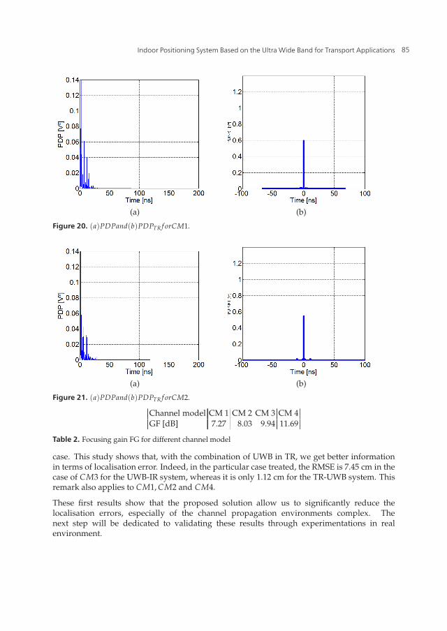
Figures 20 to 23 show a comparison between PDP and PDPTR, and, then, we can finda temporal focusing and increase the amplitude of the power from PDP to PDPTR. Thistranslates into results on the evaluation of FG in table 2.Thus we find, using successively CM1to CM4, the FG increases due, in particular, to many multipaths. Indeed, time reversal takeadvantage of the complexity of the channel, which would be very beneficial for the purposeof locating in confined environments, such as tunnels.
Simulations were performed using the channel models CM1, CM2, CM3 and CM4.Table 3presents a comparative study between the UWB-IR system and TR-UWB system, in terms oftemporal focusing and Root Mean Square Error RMSE of localisation, treated in a particular
84 New Approach of Indoor and Outdoor Localization Systems
Indoor Positioning System Based onthe Ultra Wide Band for Transport Applications 17
(a) (b)
Figure 20. (a)PDPand(b)PDPTR f orCM1.
(a) (b)
Figure 21. (a)PDPand(b)PDPTR f orCM2.
Channel model CM 1 CM 2 CM 3 CM 4GF [dB] 7.27 8.03 9.94 11.69
Table 2. Focusing gain FG for different channel model
case. This study shows that, with the combination of UWB in TR, we get better informationin terms of localisation error. Indeed, in the particular case treated, the RMSE is 7.45 cm in thecase of CM3 for the UWB-IR system, whereas it is only 1.12 cm for the TR-UWB system. Thisremark also applies to CM1, CM2 and CM4.
These first results show that the proposed solution allow us to significantly reduce thelocalisation errors, especially of the channel propagation environments complex. Thenext step will be dedicated to validating these results through experimentations in realenvironment.
85Indoor Positioning System Based on the Ultra Wide Band for Transport Applications

18 Positioning Systems
(a) (b)
Figure 22. (a)PDPand(b)PDPTR f orCM3.
(a) (b)
Figure 23. (a)PDPand(b)PDPTR f orCM4.
Channel model FG[dB] RMSE[cm] for UWB RMSE[cm] for UWB-TRCM1 7.27 2.08 = 0CM2 8.03 2.66 = 0CM3 9.94 7.45 1.12CM4 11.69 17.82 12.78
Table 3. Comparison between UWB-IR and UWB-TR in terms of FG and positionnig error in CM1, CM2, CM3 and CM4, SNR=8 dB
8. Conclusion
In this chapter, the indoor positioning system based on the UWB technique is presented. Theindoor localisation application is given, especially for railway transport. The existing indoorpositioning technique is presented. The UWB technique chosen to establish positioningsystem is introduced. Two proposed systems are presented and evaluated in terms oflocalisation error using AWGN and IEEE 802.15.3a channels. The first one is based on the
86 New Approach of Indoor and Outdoor Localization Systems
Indoor Positioning System Based onthe Ultra Wide Band for Transport Applications 19
Direct Sequence Spread Spectrum UWB technique. The second one is based on the ModifiedGegenbauer orthogonal waveforms. The simulation results show that the second proposedsystem is less sensitive to noise. This is due to the good orthogonal propriety of the MGFfunctions. These results are validated by tests using laboratory instruments. Thereafter,the new positioning system for railway application using UWB radio and Time Reversaltechniques is presented. The first results show that the combination of UWB and TimeReversal TR can reduce the localisation error thanks to the characteristic of TR technique,including the temporal focusing. In the future work, these simulations results will bevalidated by tests in real environments.
Author details
Fouzia Elbahhar, B. Fall and Marc HeddebautUniv Lille Nord de France, F-59000 Lille, France and IFSTTAR/LEOST, F-59650 Villeneuve dŠAscq- France
Atika RivenqUniv Lille Nord de France, F-59000 Lille, France and IEMN (UMR 8520 CNRS) Dept. OAE, UVHCF-59313 Valenciennes - France
Raja ElassaliTIM/ ENSA, UCAM, Avenue Prince Moulay Abdellah, B.P511-40000 Marrakech - Morocco
9. References
[1] Ingram.S.J., Harmer.D., Quinlan. M "UltraWideBand indoor positioning systems andtheir use in emergencies", Monterey, Position Location and Navigation Symposium,(PLANS) April 2004, pp. 706 - 715.
[2] Elbahhar.F, Lamari. A, Rivenq. A, Rouvaen. J. M, Heddebaut.M, Boukour.T, Sakkila.L "Novel approach of UWB multi-band system based on orthogonal function fortransports applications", The European Physical Journal Applied Physics, March 2011,53,
[3] Lamari.A, Elbahhar.F, Rivenq.A, Rouvaen J. M, Heddebaut.M "Performance Evaluationof a Multi-band UWB localisation and Communication System based on ModifiedGegenbauer Functions", Wireless personal communications (Kluwer), Vol. 34 , Issue 3,pp. 255 - 277, Aug. 2008.
[4] Chen.P.C, "A non line of sight error mitigation algorithm in location estimation". In proc.IEEE int. conf.wireless commun, networking (WCNC vol.1, New Orleans, LA, sep.1999,pp. 316 - 320.
[5] Pahlavan.K, Krishnamurthy. P, Beneat.A ;Worcester Polytech. Inst., MA "Widebandradio propagation modeling for indoor geolocation applications", CommunicationsMagazine, IEEE Volume: 36 Issue:4 , pp. 60 - 65, Apr 1998.
[6] Bhargava. V, Sichitiu. M. L, "Physical authentication through localisation in wirelesslocal area networks", Proceedings of the IEEE Global Telecommunications Conference,pp. 2658 - 2662, 2005
[7] Hatami. A, Pahlavan.K "Performance comparison of RSS and TOA indoor geolocationbased on UWB measurement of channel characteristics", Proceedings of the IEEE 17th
87Indoor Positioning System Based on the Ultra Wide Band for Transport Applications

20 Positioning Systems
International Symposium on Personal, Indoor and Mobile Radio Communications, pp.1 - 6, Helsinki, Finland.
[8] Yu.K, Montillet.J.-P, Rabbachin.A "UWB location and tracking for wireless embeddednetworks". Signal Processing, Vol. 86, No., (2006), pp. 2153 - 2171.
[9] Zhang.M, Zhang. S, Cao. J, Mei. H "A novel indoor localisation method based onreceived signal strength using discrete Fourier transform", Proceedings of the FirstInternational Conference on Communications and Networking in China, pp. 1 - 5,Beijing, China.
[10] Joseph C. Liberti, Jr., Theodore S. Rappaport, "Smart Antennas for WirelessCommunications: IS 95 and Third Generation CDMA Applications", Prentice Hallcommunications engineering and emerging technologies series, 1999
[11] B.friedlander," A passive localisation algorithm and its accuracy analysis", IEEE Journalof oceanic engineering vol.OE-12, no.1, pp.234-244, January 1987
[12] Y.T.Chan and K.C.Ho "A simple and efficient estimator for hyperbolic location", IEETransactions on signal processing, vol, 42, no.8, pp.1905-1915, August 1994.
[13] M.Laoufi "Localisation dŠusagers de la route en détresse par réseau deradiocommunications cellulaire dŠappel dŠurgence dédié" Ph.D. thesis, University ofValenciennes, France, 2003.
[14] H. Saghir, M. Heddebaut, F. Elbahhar, J.M. Rouvaen, A. Rivenq, "Train-to-waysidewireless communication in tunnel using ultra-wideband and time reversal", Ed. Elsevier,Transportation Research Part C: Emerging Technologies vol. 17, Issue 1, pp. 81-97, Feb2009.
[15] D. Abassi-moghadam, D. Tabataba Vakili, "Channel characterization of time reversalUWB communication systems", Wiley International Journal of Communication Systems,pp 601-614, published online 18 July 2010.
[16] P. Bahl and V. Padmanabhan, "RADAR: an in-building RF-based user location andtracking system", Proceedings of the Nineteenth Annual Joint Conference of the IEEEComputer and Communications Societies, Vol. 2, 2000.
[17] M. T. Shiraji, S. Yamamoto, "Human Tracking Devices: the Active Badge/Bat and DigitalAngel / Verichip systems", Project paper 1, ECE 399, Oregon State University, USA,FallTerm 2003.
[18] N.Obeid, M.Heddebaut, F.Elbahhar, C.Loyez, N.Rolland, "Millimeter Wave Ultra WideBand Short Range Radar localisation Accuracy", VTC Spring 2009.
[19] Z.Ahmadian,"Performance Analysis of the IEEE 802.15.4a UWB System",Communications", IEEE Transactions on, Volume: 57, Issue: 5 1474 - 1485,May2009.
[20] F. Elbahhar, A. Rivenq-Menha j, J.M. Rouvaen, M. Heddebaut and T. Boukour,"Comparison between DS-CDMA and Modified Gegenbauer Functions for a multi-usercommunication Ultra Wide Band system", IEE. Proceedings Communications, 152, 1021- 1028, 2005.
88 New Approach of Indoor and Outdoor Localization Systems