induced emf experiment: –when the switch is closed, the ammeter deflects momentarily –there is...
TRANSCRIPT

Induced emf• Experiment:
– When the switch is closed, the ammeter deflects momentarily
– There is an induced emf in the secondary coil (producing an induced current) due to the changing magnetic field through this coil
• When there is a steady current in the primary coil, the ammeter reads zero current– Steady magnetic fields cannot produce a current

Magnetic Flux• In general, induced emf is actually due to a change
in magnetic flux • Magnetic flux is defined similarly
to electric flux:
– Units of flux are Tm2 (or Wb)– Flux can be positive or negative
• The value of the magnetic flux through a loop/surface is proportional to the total number of field lines passing through the loop/surface
cosBAABB
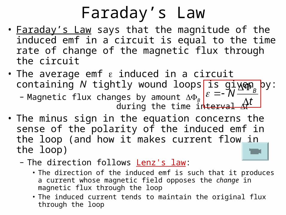
Faraday’s Law• Faraday’s Law says that the magnitude of the
induced emf in a circuit is equal to the time rate of change of the magnetic flux through the circuit
• The average emf induced in a circuit containing N tightly wound loops is given by:– Magnetic flux changes by amount B
during the time interval t
• The minus sign in the equation concerns the sense of the polarity of the induced emf in the loop (and how it makes current flow in the loop)– The direction follows Lenz's law:
• The direction of the induced emf is such that it produces a current whose magnetic field opposes the change in magnetic flux through the loop
• The induced current tends to maintain the original flux through the loop
tN B

Example Problem #20.58
Solution (details given in class):
0.121 A clockwise
The square loop shown is made of wires with a total series resistance of 10.0 . It is placed in a uniform 0.100-T magnetic field directed perpendicular into the plane of the paper. The loop, which is hinged at each corner, is pulled as shown until the separation between points A and B is 3.00 m. If this process takes 0.100 s, what is the average current generated in the loop? What is the direction of the current?

Interactive Example Problem: Flux and Induced emf in a Loop
Animation and solution details given in class.
(PHYSLET Physics Exploration 29.3, copyright Pearson Prentice Hall, 2004)

Example Problem #20.29
Solution (details given in class):(a) Right to left(b) Right to left(c) Left to right(d) Left to right
Find the direction of the current in the resistor R shown in the figure after each of the following steps (taken in the order given): (a) The switch is closed. (b) The variable resistance in series with the battery is decreased. (c) The circuit containing resistor R is moved to the left. (d) The switch is opened.

Interactive Example Problem: Lenz’s Law
Animation and solution details given in class.
(PHYSLET Physics Exploration 29.1, copyright Pearson Prentice Hall, 2004)

Applications of Faraday’s Law• Ground fault interrupter (GFI)
• Electric guitar pickups
• Magnetoencephalography (brain), magnetocardiograms (heart and surrounding nerves)

Motional emf• Consider a straight conducting bar
moving perpendicularly to the direction of a uniform external magnetic field– Free charges (e–) experience downward
force F– Creates a charge separation in the conductor– Charge separation leads to a downward electric field E– Eventually equilibrium is reached and the (downward)
magnetic force qvB on the electrons balances the (upward) electric force qE
• qE = qvB E = vB
• V = El (since E uniform)
– A potential difference is maintained across the conductor as long as there is motion through the field
• If motion is reversed, polarity of potential difference is also reversed
BlvElV
l

Motional emf• Now consider the same bar as part of
a closed conducting path– Since the area of the current loop changes
as the bar moves, an induced emf is created due to a changing magnetic flux through the loop
– An induced current is created– The direction of the current is counterclockwise (Lenz’s law)– Assume bar moves a distance x in time t
• B = BA = Blx
• From Faraday’s Law (and noting that N = 1):
Blvt
xBl
tB
(motional emf)

Motional emf• Notes on this experiment:
– The moving bar acts like a battery with an emf given by the previous formula
– Although the current tends to deplete the accumulated charge at each end of the bar, the magnetic force pumps more charge to maintain a constant potential difference
– At right is the equivalent circuit diagram– The work done by the force pulling the rod is the source of
the electrical energy– This setup is not practical; a more practical use of motional
emf is through a rotating coil of wire (electric generators)– Note that a battery can be used to drive a current, which
establishes a magnetic field, which can propel the bar

Inductive Magnetoreception in Sharks
Physics Today, March 2008
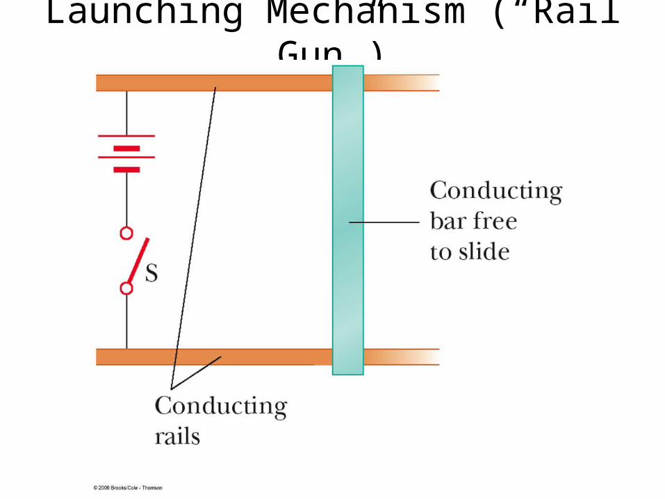
Launching Mechanism (“Rail Gun”)

Example Problem #20.21
Solution (details given in class):
(a) Toward the east
(b) 4.58 10–4 V
A car has a vertical radio antenna 1.20 m long. The car travels at 65.0 km/h on a horizontal road where the Earth’s magnetic field is 50.0 T, directed toward the north and downwards at an angle of 65.0° below the horizontal. (a) Specify the direction the car should move in order to generate the maximum motional emf in the antenna, with the top of the antenna positive relative to the bottom. (b) Calculate the magnitude of this induced emf.

Electric Generators• Alternating current (AC) generators
• Direct current (DC) generators
tNBA sinN = # turns in loop coil B = magnetic field strength A = Area of the loop coil = angular rotation speed
max = NBA (plane of loop parallel to magnetic field)
min = 0 (plane of loop perpendicular to magnetic field)
f = 60 Hz (U.S.)
(2f )
(= t)
(note similarity to DC motor – Chap. 19)

Motors and Back emf• Generators convert mechanical energy to electrical
energy• Motors convert electrical
energy to mechanical energy generators run in reverse
• As the coil in the motor rotates, the changing magnetic flux through it induces an emf– This emf acts to reduce the current in the coil (in
agreement with Lenz’s law)– For this reason, the emf is called a back emf – Power requirements for starting a motor or running it under
heavy loads larger than running under average loads

Self-Inductance• Consider the effect of current flow in
a simple circuit with a battery and a resistor– Faraday’s law prevents the current from
reaching its maximum value ( / R) immediately after switch is closed
• Magnetic flux through the loop changes as current increases• Resulting induced emf acts to reduce total emf of circuit
– When the rate of current change lessens as current increases, induced emf decreases
• Another example: increasing and decreasing current in a solenoid coil

Self-Inductance• These effects are called self-induction• The emf that is produced is called self-induced emf
(or back emf)
– L is a constant called the inductance– The minus sign indicates that a changing current induces
an emf that is in opposition to that change– Units of inductance is the henry (H) 1 H = 1 Vs / A
• An expression for inductance can be found by equating Faraday’s law with the above:
t
IL
IN
INL BB

RL Circuits• A circuit element having a large inductance is called
an inductor• From we see that an inductor acts as a
current stabilizer – The larger the inductance in a circuit, the larger the
opposition to the rate of change of the current– Remember that resistance is a measure of the opposition
to current
• Consider a series circuit consisting of a battery, resistor, and inductor– Current changes most rapidly
when switch is first closed• Back emf largest at this point
t
ILL
(Series RL circuit)

RL Circuits• Using calculus, we can derive an
expression for the current in the circuit as a function of time
– Similar to charge q as a function of time for a charging capacitor
– Like RC circuits, there is a time constant for the circuit:
• When the switch is opened, the current in the circuit decreases exponentially with time
LRteR
I /1
R
L
LRteR
I /
(rise of current)
(decay of current)

Example Problem #20.53
Solution (details given in class):
(a) 20.0 ms
(b) 37.9 V
(c) 1.52 mV
(d) 51.8 mA
An 820-turn wire coil of resistance 24.0 is placed on top of a 12500-turn, 7.00-cm-long solenoid as shown. Both coil and solenoid have cross-sectional areas of 1.00×10⁻⁴ m2. (a) How long does it take the solenoid current to reach 0.632 times its maximum value? (b) Determine the average back emf caused by the self-inductance of the solenoid during this interval. (c) The magnetic field produced by the solenoid at the location of the coil is ½ as strong as the field at the center of the solenoid. Determine the average rate of change in magnetic flux through each turn of the coil during the stated interval. (d) Find the magnitude of the average induced current in the coil.