induced thermo-mechanical stress in cpv receivers with
TRANSCRIPT

Induced Thermo-Mechanical Stress In CPV Receivers With Cycled High Intensity Light
Valentín Pérez, Ignacio Antón, Rebeca Herrero, Eduardo Nogueira, Rubén Núñez, Carlos del Cañizo, Gabriel Sala
Abstract. CPV receivers are made of materials with very different lineal expansion coefficients. Strong variations in DNI due to the passage of clouds can cause sudden temperature changes that creates mechanical stress. For common solder and metal filled polymers the plastic limit could be reached causing substantial fatigue. The best forecast of receiver reliability is therefore achieved by applying an intermittent light source with nominal irradiance level and a number of cycles equal to the expected cloud passages for a given site. The UPM has developed specialized equipment, dubbed the LYSS (Light cYcling Stressing Source), for carrying out such experiments. The small thermal capacity of receivers allows simulating more than 25000 cycles per week. The number of deep transients expected for Madrid in 30 years operation, based on available data, is about 45000. We are currently using the system to cycle a "Ge/Ag Epoxy/ aluminum" receiver, which shows no degradation after 20000 cycles. The equipment can cast up to 200 and 70 W/cm2
on 0.1 and 1 cm2 cells, respectively.
INTRODUCTION
The natural thermal cycling of cells and receivers in CPV modules has been considered a possible weak point for reliability in the field. At the same time, there is the suspicion that the thermal mechanical stress induced by the sudden changes of very high irradiance levels on the cells, commonly caused by clouds, could be a source of failure. The reliability of CPV modules and receivers is not a subject of IEC 62108 because it is a Qualification Standard. Reproducing the fast heating of the cells respect to the heat sink requires casting high irradiance beam because a safe forward cell bias is not enough for reaching the actual temperature variation in operation.
EFFECTS OF TRANSIENT ILLUMINATION ON CPV RECEIVERS
Qualification of module design and detection of early failures in CPV modules is the aim of IEC 62108 It provides to customers a high degree of confidence and to manufacturers a faster convergence to reliable CPV module technology.
Accelerated tests based on relativity slow thermal cycling from very low to high temperature can approximate the effects of aging on several components and interfaces. But the fast stress caused
by sudden variation of irradiance is not reproduced at operational conditions in the IEC 62108.
Therefore, we believe that the question of reliability of chip bonding, substrate gluing and wiring of CPV receivers under transient concentrated illumination is not effectively answered by current version of IEC 62108 standard. However, that issue is significant because large increase of thermal or electrical contact resistance could conclude with a fast lethal destructive runaway or receivers.
MJ Solar Cell (Ge)
/ Solder or Ag Epoxy
I *-;^s' Substrate (Al or C u ) I ¡r I ^ . Gluing &
.—i * r ' ¡ insulating (soft)
^ = — Metal plate (Al alloy)
FIGURE 1. The classic multilayer system found in a CPV receiver under a point focus POE
In order to clarify this uncertainty, the CPV team at IES-UPM is developing equipment and experiments for exploring the effect of light transients, which cause thermal-mechanical stress, on the reliability of receivers within the EU-FP7 funded ECOSOLE project.
Solder bonding (for example tin-lead-silver) or bulky adhesive polymers loaded with metallic particles (like Epoxy with silver or copper) perform the thermal,
This article is in the article. R« msconditions. Downloaded to IP: 138.4.46.22
On:Tue, 10 Feb 2015 10:11:20
mechanical and electrical connection of concentrator cells to their carrier substrates. Fig. 1 shows the classic structure of cell-on-carrier and heat sink for a CPV module. It is also common that a secondary optic is coupled to the cell, complicating the receiver structure.
TABLE 1. Mechanical properties of receiver elements Material Lin. Coef. Young Mod Yield
Exp. point (10 6 °C ') (GPa) (MPa)
Ge (3MJ) Tin Solder Lead Al (alloy) Copper Epoxy+Ag
5,9 24
28,9 23,1 16,5
15-34
103 47 16 70 130 10,5
9000 9-14 12
400 70
12-30
Table 1 lists the thermal mechanical characteristics of commonly used materials in CPV receivers and modules. These components show very different linear expansion coefficients. Rough calculations suggest that the interfaces between the cell and substrates could suffer significant stress, close to or beyond yield stress, that is the materials may operate in the plastic regime. Also, finite-element simulations of real 3-D interfaces in receivers, indicated the possibility of cycling up to plastic mode in real world. Although simulation of homogeneous solder layer could seem valid, in the real world we usually find voids at random in that layer that can affect the mechanical and thermal performance.
For the solder the maximum stress should happen during solder solidification of tin-lead-silver alloy which requires more than 200°C. Then cycling at lower temperature lasts for the rest of system lifetime modifying the initial stress. Epoxies and other polymers are cured at lower temperatures, then the maximum stress happens only at normal operation. We must also take into account the fact that both solder and polymers are not really bonded to the semiconductor (typically Ge in MJ cells) but to the coated or alloyed back metal layer, which can be removed from the semiconductor as effect of the shear stress.
Therefore, because simulation or modeling could be insufficient nor convincing, the variability of receiver structures and interfaces justifies investigating their reliability with a suitable experiment that tries to reproduce the real effect of cloud passage on CPV modules
DEFINITION OF RECEIVER STRESSING TEST
Number Of Required Test Cycles
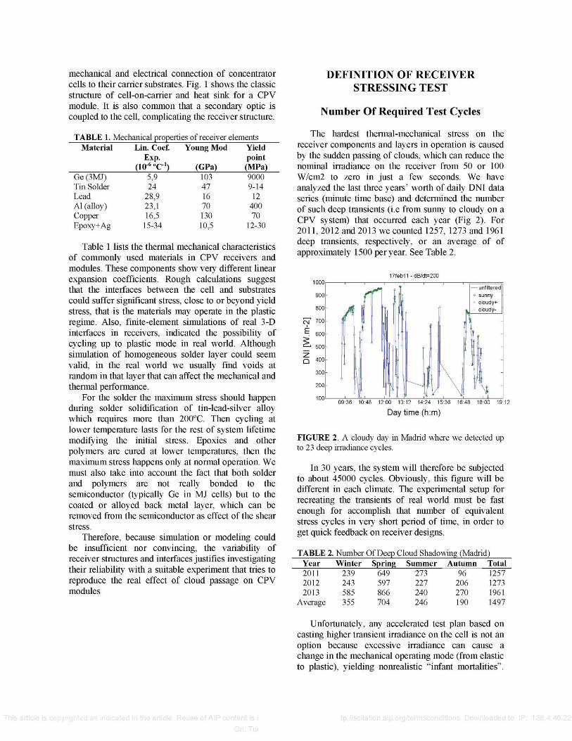
The hardest thermal-mechanical stress on the receiver components and layers in operation is caused by the sudden passing of clouds, which can reduce the nominal irradiance on the receiver from 50 or 100 W/cm2 to zero in just a few seconds. We have analyzed the last three years' worth of daily DNI data series (minute time base) and determined the number of such deep transients (i.e from sunny to cloudy on a CPV system) that occurred each year (Fig 2). For 2011, 2012 and 2013 we counted 1257, 1273 and 1961 deep transients, respectively, or an average of of approximately 1500 per year. See Table 2.
17feb11 -dB/dt=200
09:36 10:48 12:00 13:12 14:24 15:36 16:48 18:00 19:12
Daytime (h:m)
FIGURE 2. A cloudy day in Madrid where we detected up to 23 deep irradiance cycles.
In 30 years, the system will therefore be subjected to about 45000 cycles. Obviously, this figure will be different in each climate. The experimental setup for recreating the transients of real world must be fast enough for accomplish that number of equivalent stress cycles in very short period of time, in order to get quick feedback on receiver designs.
TABLE 2. Number Of Deep Cloud Shadowing (Madrid) Year 2011 2012 2013
Average
Winter 239 243 585 355
Spring 649 597 866 704
Summer 273 227 240 246
Autumn 96
206 270 190
Total 1257 1273 1961 1497
Unfortunately, any accelerated test plan based on casting higher transient irradiance on the cell is not an option because excessive irradiance can cause a change in the mechanical operating mode (from elastic to plastic), yielding nonrealistic "infant mortalities".
This article is I in the article. Reuse of AIP content is :
On: Tui
tp://scitation.aip.org/termsconditions. Downloaded to IP: 138.4.46.22

The only option for moderate acceleration can be carried out increasing the base plate (heat sink) temperature where the receivers are attached during the test. The heat sink temperature can be associated to ambient temperature of a particular CPV site period of the year.
Durations Of The Cycles
To define what is the adequate minimum duration of illumination and dark periods that reproduces the real transitory dynamics is important, not only for imitating reality but for reducing the required time for cycling 45000 times.
The minimum cycle period depends of the heat capacity and thermal resistances of the receiver elements. Although they can be estimated by calculation, we have recorded the cell temperature along one cycle using Voc as thermal sensor. The sample consisted of a MJ cell, 3x3 mm, glued with silver epoxy on an aluminum plate 3x4x0.3 cm3. It is thermally attached to a large heat sink whose temperature is controlled.
P " • ° t Temperature monitoring at substrate (Point B)
1700 1750 1800 1850
Time (s)
FIGURE 3. Equivalent thermal circuit and evolution of temperature at the substrate top during cycling: Steady state is reached in 10 seconds.
TABLE 3. Thermal parameter of receiver Element Size Rth Cth Tth (s)
(cm)x(cm2) (°K/W) (J/"K) Cell(Ge) (3.10-2)x(0.1) 5,0 104 8.1 10"4 4.0 10"4
Solder (3.10-2)x(0.1) 2.3 104 2.2 10"4 5.0 10"5
Epoxy Ag (3.10-2)x(0.1) 7.9 2.7 10"3 2.2 10"2
Alsubs (0.3)x(12) 2.5 10"2 7.3 1.8 104
Glue Tape (0.03)x(12) 0.3 4.2 104 1.3 104
Table 3 shows the approximate values of the thermal constants of the elements of the circuit and the time constants of each RC pair.
From the records of cell temperature (point A in Fig. 3) the thermocouple measurement in point B and the constants of Table 3 we conclude that the cell temperature rises very fast (in several milliseconds) with respect to the substrate due to the thermal drop in
This article is ndicated in the article. Reuse of AIP con
Rceii&soider- Afterwards, the substrate heats up much more slowly, reaching steady state about 10 seconds later. The temperature drop between point A and B is constant while the light is on or off on the cell. See Fig. 3.
In conclusion, after less than 10 second of illumination the whole receiver reaches steady state, with a similar transient duration when the light is removed. The shortest reasonable period proposed will last 20 seconds, the minimum. It allow for 21600 cycles in continuous operation 5 days a week. Improving it, the cycling can be shared among 2 cells, oscillating the beam from one cell to other. It currently increases the rate of the experiment up to to 28800 cycles per week (not the double because the time passing the light from one cell to the other is not negligible). With this specific experiment the reliability of any receiver vs. transient mode illumination can be experimentally established (for the Madrid case). This extremely high rate means that is possible to test several samples in a short period, although a longer cycling period could be necessary for different interfacing layers and soldering materials, depending on their thermal characteristics. We must also consider the possibility that the duration of the steady-state hot and cold time periods could affect failure dynamics (ie. creep), and once will study slowing the cycling rate in later work.
Overall Description Of Proposed Test
The test will consist of intermittently casting collimated light generated by a continuous xeon arc lamp which is concentrated by reflexive optics onto the cell-on-carriers to be tested. The experiment and the lamp lifetime can be optimized testing two samples located on the same large base plate fixed at controlled temperature. The concentrating mirror is rotated such that the light spot is cast, alternately, on one cell or the other, such that the illumination time for cell n° 1 becomes dark time for cell n° 2 and, vice versa. The distance between cells on the heat sink is large enough to avoid any thermal link across the heat sink.
The overall test rate, for the receivers currently being tested, is such than 2 cells are cycled every 30 seconds, with 5 seconds used for each light spot movement. The duration of the cycles is specific for each receiver technology, with the aim of reaching, at least, the thermal steady-state under light and dark states, as described in the last section.. Modes with longer time on each state can be adopted when the soldering materials are affected by this parameter.
Each cell under test can be at short-circuit or open circuit during cycling. A dark IV curve is recorded every N cycles (N typically between 250 to 500) in order to monitor degradation evolution or to detect
tions. Downloaded to IP: 138.4.46.22

fatal breakdown before ending the overall test plan. The final accurate measurement of degradation is carried out in a solar simulator at STC.
DESCRIPTION OF THE NEW CYCLING EQUIPMENT
We have implemented a device called Light cYcling Stressing Source, (LYSS) to carry the test described above. The functional blocks of the device are shown in Fig. 4 and the actual equipment in Fig. 5. We have used a continuous xenon-arc lamp, able to provide 250 W of luminous power (400 to 2000 nm). The lamp beam is concentrated on a focal point by an off-axis parabolic dish mirror.
The receiver, with or without SOE, is located in this focal point. By means of a mechanical actuator the beam can be directed alternatively over two receivers, then increasing the testing rate. The limited collimation of the lamp beam asked to use an optical intensifier in order to reach the level of 200 W/cm2 and 70W/cm2 on cells 0.1 and 1 cm2 cell respectively.
FIGURE 4. Functional blocks of the LYSS machine (Light cYcling Stressing Source)
The receiver is thermally attached during the experiment to a large thermal base equipped with Peltier elements which acts as heat sink. During the light cycling the base temperature can be programmed to static or slowly cycling within the range 20 to 100 ºC. The user is responsible for selecting the base temperature, the durations of a light-dark cycles and the number of cycles between DIV tests (For example: 60ºC, 10 s, 500 cycles). At the frequency commanded by the user, the equipment measures and stores the dark IV curve of each cell, from which the series resistance is calculated. In case of fast increase of Rs
or any degradation the experiment is programmed to automatically stop.
FIGURE 5. View of the actual equipment “LYSS machine” with open doors. Size is 1.2x0.7x1.0 m
EXPERIMENTAL RESULTS
Two receivers consisting of 0.1 cm2 MJ cells, attached with silver-epoxy on an aluminum substrate have been cycled at 100W/cm2 along 20000 transient cycles on a 60 ºC heat sink without any problem. The evolution of the series resistance is insignificant after 20000 cycles, but the reliability test for Madrid is not finished yet, requiring reaching 45000 per cell on several cells. See Fig. 6.
Evolution Rseries vs. Light Cycling
0.3
0.28
0.26
= 0.24
0.22
0.2
Results: 2.2% increase after 20000 cycles
5000 10000 15000 Number Light-Dark Cycles
20000
FIGURE 6. Evolution of series resistance obtained from dark IV curve recorded after each 250 cycles.
CONCLUSIONS
The LYSS machine has been designed, built, and put into continuous operation. The tool is ready for analyzing the reliability of any type of receiver sample, such as metal plate, DCB or IMS substrates with or without SOE. The equipment is available for providing service to CPV companies and laboratories for advising on the reliability of their receiver for the whole life time of the CPV system.
This article is copyrighted as indicated in the article. Reuse of AIP content is subject2 t5o7 the terms at: ions. Downloaded to IP: 138.4.46.22
On: Tue, 10 Feb 2015 10:11:20

ACKNOWLEDGEMENTS
The research leading to these results has received funding from the European Union Seventh Framework Programme FP7/2007-2013 under grant agreement n° 295958 (Project acronym: ECOSOLE)
REFERENCES
1. IEC 62108 Concentrator Photovoltaic (CPV) Modules & Assemblies -Design Qualification & Type Approval Ed. 1
This article is i in the article. Reuse of AIP content ittp://scitation.aip.org/termsconditions. Downloaded to IP: 138.4.46.22
On: )