induction motors notes - weeblymrasdstore.weebly.com/uploads/2/4/1/8/24182730/... · design of...
TRANSCRIPT
1
Design of Induction Motors
Introduction:
Induction motors are the ac motors which are employed as the prime movers in most of
the industries. Such motors are widely used in industrial applications from small workshops to
large industries. These motors are employed in applications such as centrifugal pumps,
conveyers, compressors crushers, and drilling machines etc.
Constructional Details:
Similar to DC machines an induction motor consists of a stationary member called stator and a
rotating member called rotor. However the induction motor differs from a dc machine in the
following aspects.
1. Laminated stator
2. Absence of commutator
3. Uniform and small air gap
4. Practically almost constant speed
The AC induction motor comprises two electromagnetic parts:
• Stationary part called the stator
• Rotating part called the rotor
The stator and the rotor are each made up of
• An electric circuit, usually made of insulated copper or aluminum winding, to carry
current
• A magnetic circuit, usually made from laminated silicon steel, to carry magnetic flux
The stator
The stator is the outer stationary part of the motor, which consists of
• The outer cylindrical frame of the motor or yoke, which is made either of welded sheet
steel, cast iron or cast aluminum alloy.
• The magnetic path, which comprises a set of slotted steel laminations called stator
core pressed into the cylindrical space inside the outer frame. The magnetic path is
laminated to reduce eddy currents, reducing losses and heating.
• A set of insulated electrical windings, which are placed inside the slots of the laminated
stator. The cross-sectional area of these windings must be large enough for the power
rating of the motor. For a 3-phase motor, 3 sets of windings are required, one for each
2
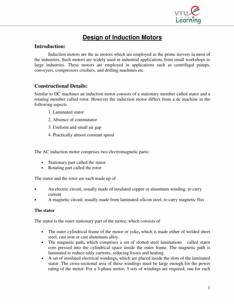
phase connected in either star or delta. Fig 1 shows the cross sectional view of an
induction motor. Details of construction of stator are shown in Figs 4-6.
Fig 1: Stator and rotor laminations
The rotor
Rotor is the rotating part of the induction motor. The rotor also consists of a set of slotted
silicon steel laminations pressed together to form of a cylindrical magnetic circuit and the
electrical circuit. The electrical circuit of the rotor is of the following nature
Squirrel cage rotor consists of a set of copper or aluminum bars installed into the slots, which
are connected to an end-ring at each end of the rotor. The construction of this type of rotor
along with windings resembles a ‘squirrel cage’. Aluminum rotor bars are usually die-cast into
the rotor slots, which results in a very rugged construction. Even though the aluminum rotor
bars are in direct contact with the steel laminations, practically all the rotor current flows
through the aluminum bars and not in the lamination
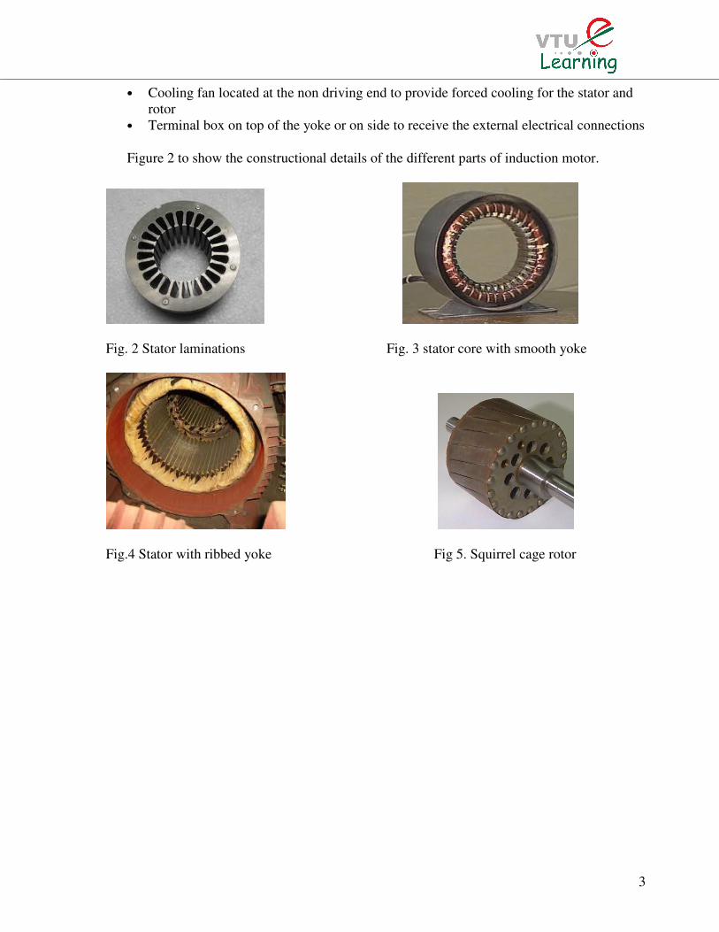
Wound rotor consists of three sets of insulated windings with connections brought out to three
slip rings mounted on one end of the shaft. The external connections to the rotor are made
through brushes onto the slip rings as shown in fig 7. Due to the presence of slip rings such
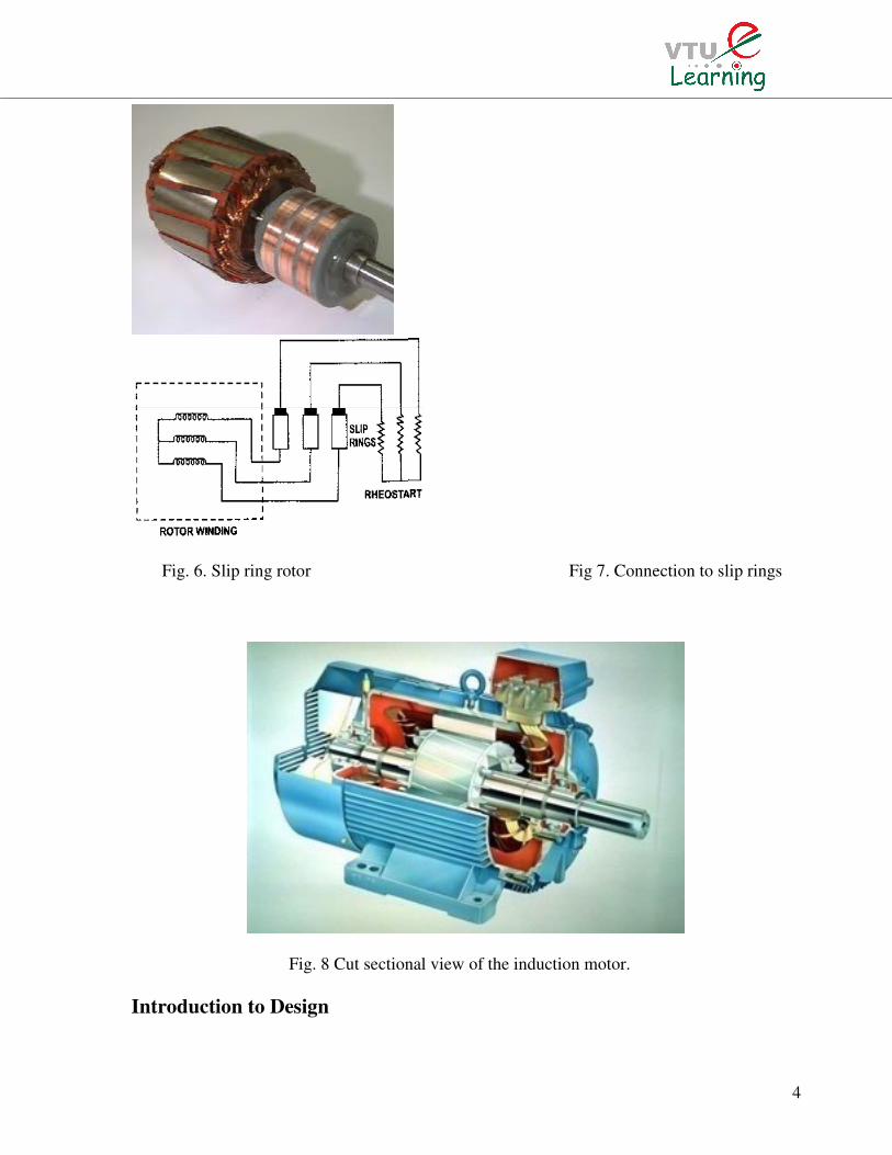
type of motors are called slip ring motors. Sectional view of the full induction motor is shown
in Fig. 8
Some more parts, which are required to complete the constructional details of an induction
motor, are:
• Two end-flanges to support the two bearings, one at the driving-end and the other at the
non driving-end, where the driving end will have the shaft extension.
• Two sets of bearings to support the rotating shaft,
• Steel shaft for transmitting the mechanical power to the load
3
• Cooling fan located at the non driving end to provide forced cooling for the stator and
rotor
• Terminal box on top of the yoke or on side to receive the external electrical connections
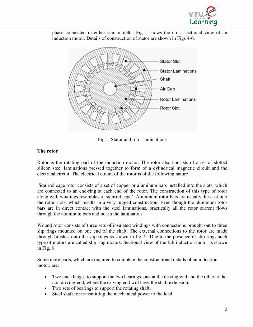
Figure 2 to show the constructional details of the different parts of induction motor.
Fig. 2 Stator laminations Fig. 3 stator core with smooth yoke
Fig.4 Stator with ribbed yoke Fig 5. Squirrel cage rotor
4
Fig. 6. Slip ring rotor Fig 7. Connection to slip rings
Fig. 8 Cut sectional view of the induction motor.
Introduction to Design
5
The main purpose of designing an induction motor is to obtain the complete physical
dimensions of all the parts of the machine as mentioned below to satisfy the customer
specifications. The following design details are required.
1. The main dimensions of the stator.
2 Details of stator windings.
3. Design details of rotor and its windings
4. Performance characteristics.
In order to get the above design details the designer needs the customer specifications
Rated out put power, rated voltage, number of phases, speed, frequency, connection of stator
winding, type of rotor winding, working conditions, shaft extension details etc.
In addition to the above the designer must have the details regarding design equations based on
which the design procedure is initiated, information regarding the various choice of various
parameters, information regarding the availability of different materials and the limiting values
of various performance parameters such as iron and copper losses, no load current, power
factor, temperature rise and efficiency
Output Equation: output equation is the mathematical expression which gives the relation
between the various physical and electrical parameters of the electrical machine.
In an induction motor the out put equation can be obtained as follows
Consider an ‘m’ phase machine, with usual notations
Out put Q in kW = Input x efficiency
Input to motor = mVph Iph cos Φ x 10-3
kW
For a 3 Φ machine m = 3
Input to motor = 3Vph Iph cos Φ x 10-3
kW
Assuming Vph = Eph, Vph = Eph = 4.44 f Φ TphKw
= 2.22 f ΦZphKw
f = PNS/120 = Pns/2,
6
Output = 3 x 2.22 x Pns/2 x ΦZphKw Iph η cos Φ x 10-3
kW
Output = 1.11 x PΦ x 3Iph Zph x ns Kw η cos Φ x 10-3
kW
PΦ = BavπDL, and 3Iph Zph/ πD = q
Output to motor = 1.11 x BavπDL x πDq x ns Kw η cos Φ x 10-3
kW
Q = (1.11 π2 Bav q Kw η cos Φ x 10
-3) D
2L ns kW
Q = (11 Bav q Kw η cos Φ x 10-3
) D2L ns kW
Therefore Output Q = Co D2L ns kW
where Co = (11 Bav q Kw η cos Φ x 10-3
)
Vph = phase voltage ; Iph = phase current
Zph = no of conductors/phase
Tph = no of turns/phase
Ns = Synchronous speed in rpm
ns = synchronous speed in rps
p = no of poles, q = Specific electric loading
Φ = air gap flux/pole; Bav = Average flux density
kw = winding factor
η = efficiency
cosΦ= power factor
D = Diameter of the stator,
L = Gross core length
Co = Output coefficient
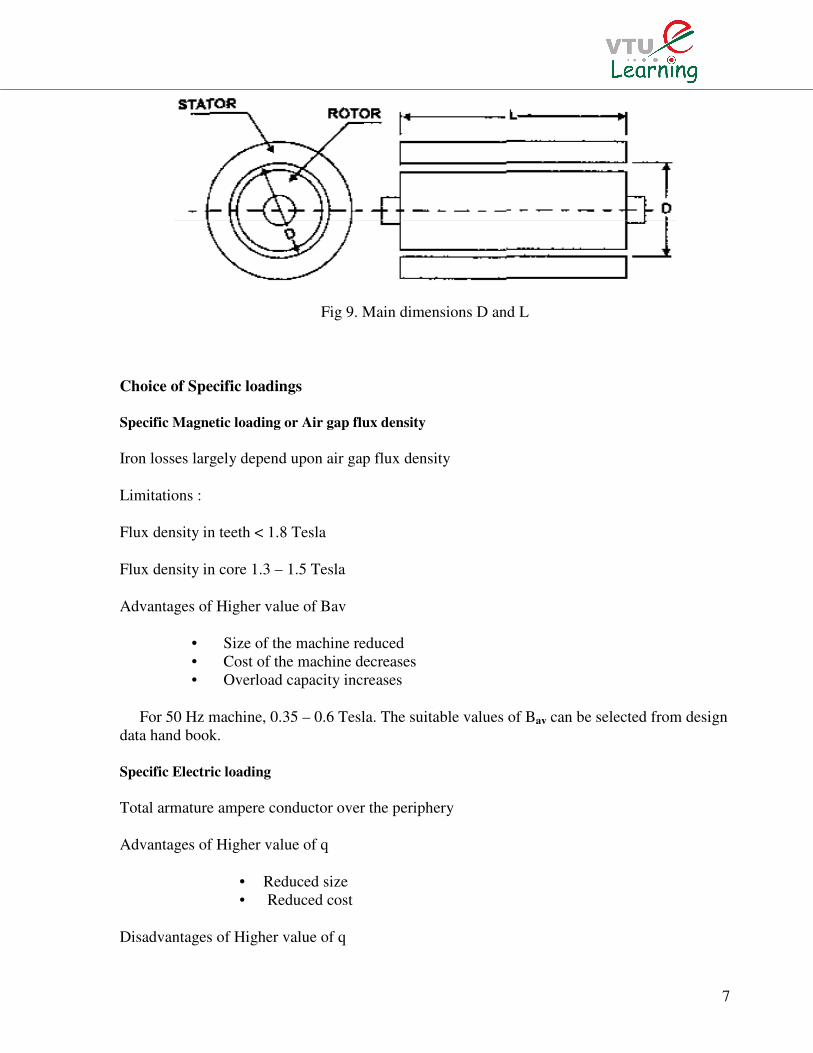
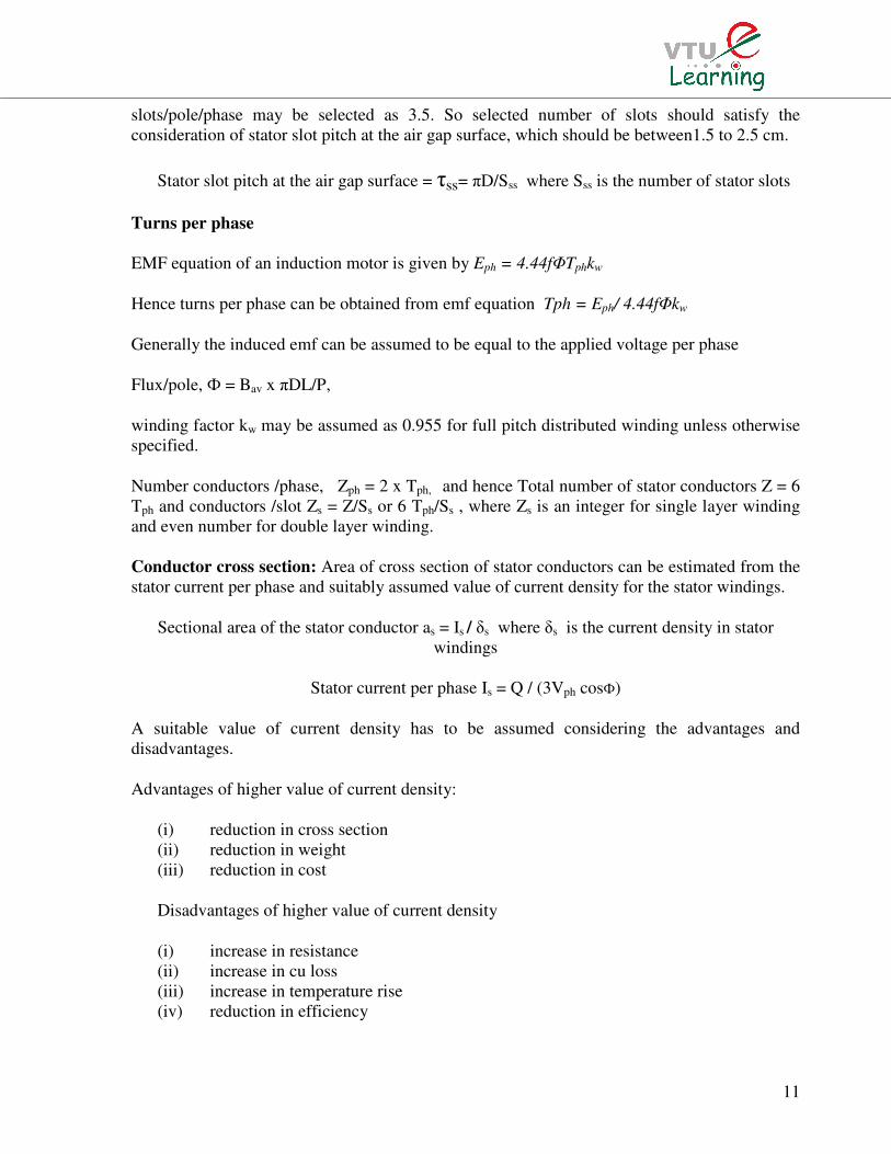
Fig.9 shows the details of main dimensions of the of an induction motor.
7
Fig 9. Main dimensions D and L
Choice of Specific loadings
Specific Magnetic loading or Air gap flux density
Iron losses largely depend upon air gap flux density
Limitations :
Flux density in teeth < 1.8 Tesla
Flux density in core 1.3 – 1.5 Tesla
Advantages of Higher value of Bav
• Size of the machine reduced
• Cost of the machine decreases
• Overload capacity increases
For 50 Hz machine, 0.35 – 0.6 Tesla. The suitable values of Bav can be selected from design
data hand book.
Specific Electric loading
Total armature ampere conductor over the periphery
Advantages of Higher value of q
• Reduced size
• Reduced cost
Disadvantages of Higher value of q
8
• Higher amount of copper
• More copper losses
• Increased temperature rise
• Lower overload capacity
Normal range 10000 ac/m – 450000 ac/m. The suitable values of q can be selected from design
data hand book.
Choice of power factor and efficiency
Choice of power factor and efficiency under full load conditions will increase with increase in
rating of the machine. Percentage magnetizing current and losses will be lower for a larger
machine than that of a smaller machine. Further the power factor and efficiency will be higher
for a high speed machine than the same rated low speed machine because of better cooling
conditions. Taking into considerations all these factors the above parameters will vary in a
range based on the output of the machine. Similar to Bav and q, efficiency and power factor
values can be selected from Design data hand book.
Separation of D and L
The output equation gives the relation between D2L product and output of the machine. To
separate D and L for this product a relation has to be assumed or established. Following are the
various design considerations based on which a suitable ratio between gross length and pole
pitch can be assumed.
i. To obtain minimum over all cost 1.5 to 2.0
ii. To obtain good efficiency 1.4 to 1.6
iii. To obtain good over all design 1.0 to 1.1
iv. To obtain good power factor 1.0 to 1.3
As power factor plays a very important role the performance of induction motors it is advisable
to design an induction motor for best power factor unless specified. Hence to obtain the best
power factor the following relation will be usually assumed for separation of D and L.
Pole pitch/ Core length = 0.18/pole pitch
or (πD/p) / L= 0.18/ (πD/p)
i.e D = 0.135P√L where D and L are in meter.
9
Using above relation D and L can be separated from D2L product. However the obtained
values of D and L have to satisfy the condition imposed on the value of peripheral speed.
Peripheral Speed
For the normal design of induction motors the calculated diameter of the motor should be such
that the peripheral speed must be below 30 m/s. In case of specially designed rotor the
peripheral speed can be 60 m/s.
Design of Stator
Stator of an induction motor consists of stator core and stator slots.
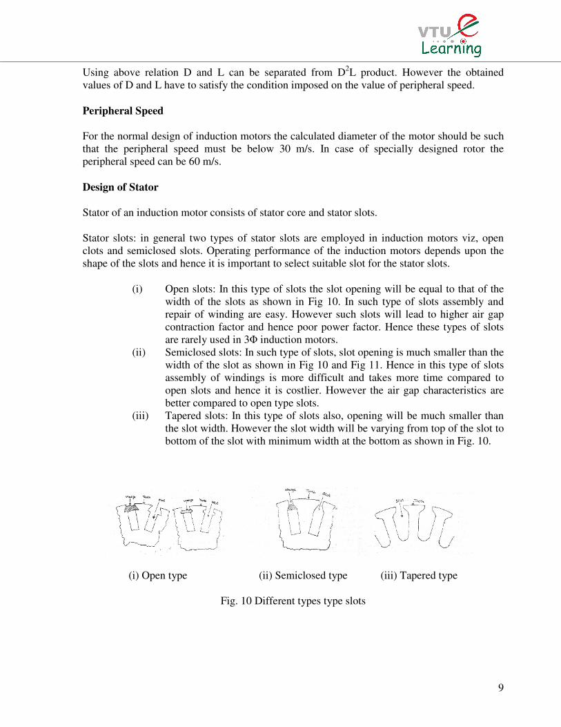
Stator slots: in general two types of stator slots are employed in induction motors viz, open
clots and semiclosed slots. Operating performance of the induction motors depends upon the
shape of the slots and hence it is important to select suitable slot for the stator slots.
(i) Open slots: In this type of slots the slot opening will be equal to that of the
width of the slots as shown in Fig 10. In such type of slots assembly and
repair of winding are easy. However such slots will lead to higher air gap
contraction factor and hence poor power factor. Hence these types of slots
are rarely used in 3Φ induction motors.
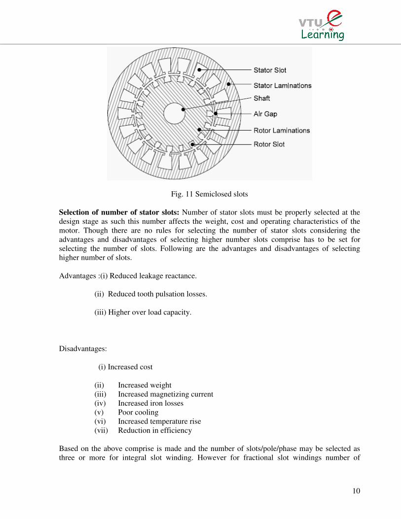
(ii) Semiclosed slots: In such type of slots, slot opening is much smaller than the
width of the slot as shown in Fig 10 and Fig 11. Hence in this type of slots
assembly of windings is more difficult and takes more time compared to
open slots and hence it is costlier. However the air gap characteristics are
better compared to open type slots.
(iii) Tapered slots: In this type of slots also, opening will be much smaller than
the slot width. However the slot width will be varying from top of the slot to
bottom of the slot with minimum width at the bottom as shown in Fig. 10.
(i) Open type (ii) Semiclosed type (iii) Tapered type
Fig. 10 Different types type slots
10
Fig. 11 Semiclosed slots
Selection of number of stator slots: Number of stator slots must be properly selected at the
design stage as such this number affects the weight, cost and operating characteristics of the
motor. Though there are no rules for selecting the number of stator slots considering the
advantages and disadvantages of selecting higher number slots comprise has to be set for
selecting the number of slots. Following are the advantages and disadvantages of selecting
higher number of slots.
Advantages :(i) Reduced leakage reactance.
(ii) Reduced tooth pulsation losses.
(iii) Higher over load capacity.
Disadvantages:
(i) Increased cost
(ii) Increased weight
(iii) Increased magnetizing current
(iv) Increased iron losses
(v) Poor cooling
(vi) Increased temperature rise
(vii) Reduction in efficiency
Based on the above comprise is made and the number of slots/pole/phase may be selected as
three or more for integral slot winding. However for fractional slot windings number of
11
slots/pole/phase may be selected as 3.5. So selected number of slots should satisfy the
consideration of stator slot pitch at the air gap surface, which should be between1.5 to 2.5 cm.
Stator slot pitch at the air gap surface = τss= πD/Sss where Sss is the number of stator slots
Turns per phase
EMF equation of an induction motor is given by Eph = 4.44fΦTphkw
Hence turns per phase can be obtained from emf equation Tph = Eph/ 4.44fΦkw
Generally the induced emf can be assumed to be equal to the applied voltage per phase
Flux/pole, Ф = Bav x πDL/P,
winding factor kw may be assumed as 0.955 for full pitch distributed winding unless otherwise
specified.
Number conductors /phase, Zph = 2 x Tph, and hence Total number of stator conductors Z = 6
Tph and conductors /slot Zs = Z/Ss or 6 Tph/Ss , where Zs is an integer for single layer winding
and even number for double layer winding.
Conductor cross section: Area of cross section of stator conductors can be estimated from the
stator current per phase and suitably assumed value of current density for the stator windings.
Sectional area of the stator conductor as = Is / δs where δs is the current density in stator
windings
Stator current per phase Is = Q / (3Vph cosФ)
A suitable value of current density has to be assumed considering the advantages and
disadvantages.
Advantages of higher value of current density:
(i) reduction in cross section
(ii) reduction in weight
(iii) reduction in cost
Disadvantages of higher value of current density
(i) increase in resistance
(ii) increase in cu loss
(iii) increase in temperature rise
(iv) reduction in efficiency
12
Hence higher value is assumed for low voltage machines and small machines. Usual value
of current density for stator windings is 3 to 5 amps.
Based on the sectional area shape and size of the conductor can be decided. If the sectional
area of the conductors is below 5 mm2
then usually circular conductors are employed. If it
is above 5 mm2
then rectangular conductors will be employed. Standard bare size of round
and rectangular conductors can be selected by referring the tables of conductors given in
Design data Hand book. In case of rectangular conductors width to thickness ratio must be
between 2.5 to 3.5.
Area of stator slot: Slot area is occupied by the conductors and the insulation. Out of
which almost more than 25 % is the insulation. Once the number of conductors per slot is
decided approximate area of the slot can be estimated.
Slot space factor = Copper area in the slot /Area of each slot
This slot space factor so obtained will be between 0.25 and 0.4. The detailed dimension of
the slot can be estimated as follows.
Size of the slot: Normally different types of slots are employed for carrying stator
windings of induction motors. Generally full pitched double layer windings are employed
for stator windings. For double layer windings the conductor per slot will be even. These
conductors are suitably arranged along the depth and width of the winding. Stator slots
should not be too wide, leading to thin tooth width, which makes the tooth mechanically
weak and maximum flux density may exceed the permissible limit. Hence slot width
should be so selected such that the flux density in tooth is between 1.6 to 1.8 Tesla. Further
the slots should not be too deep also other wise the leakage reactance increases. As a
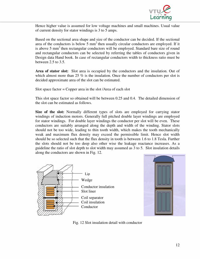
guideline the ratio of slot depth to slot width may assumed as 3 to 5. Slot insulation details
along the conductors are shown in Fig. 12.
Fig. 12 Slot insulation detail with conductor
Wedge
Conductor insulation
Slot liner
Coil separator
Coil insulation
Conductor
Lip
13
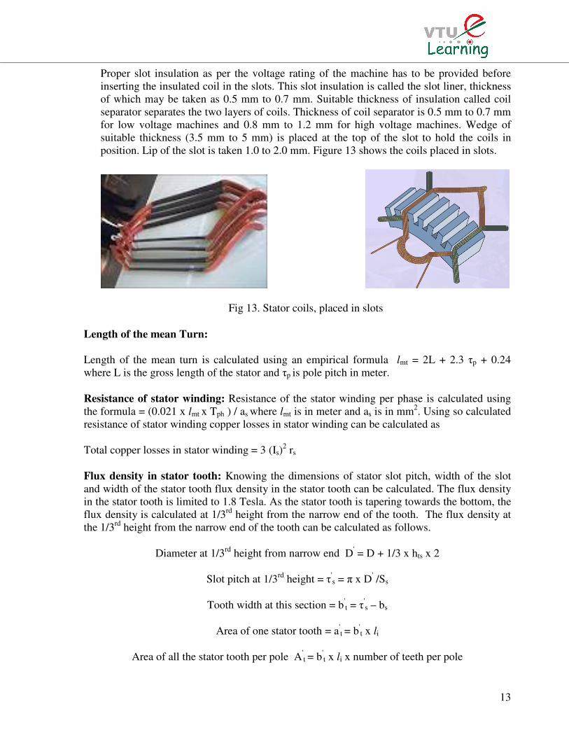
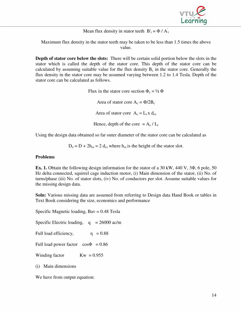
Proper slot insulation as per the voltage rating of the machine has to be provided before
inserting the insulated coil in the slots. This slot insulation is called the slot liner, thickness
of which may be taken as 0.5 mm to 0.7 mm. Suitable thickness of insulation called coil
separator separates the two layers of coils. Thickness of coil separator is 0.5 mm to 0.7 mm
for low voltage machines and 0.8 mm to 1.2 mm for high voltage machines. Wedge of
suitable thickness (3.5 mm to 5 mm) is placed at the top of the slot to hold the coils in
position. Lip of the slot is taken 1.0 to 2.0 mm. Figure 13 shows the coils placed in slots.
Fig 13. Stator coils, placed in slots
Length of the mean Turn:
Length of the mean turn is calculated using an empirical formula lmt = 2L + 2.3 τp + 0.24
where L is the gross length of the stator and τp is pole pitch in meter.
Resistance of stator winding: Resistance of the stator winding per phase is calculated using
the formula = (0.021 x lmt x Tph ) / as where lmt is in meter and as is in mm2. Using so calculated
resistance of stator winding copper losses in stator winding can be calculated as
Total copper losses in stator winding = 3 (Is)2 rs
Flux density in stator tooth: Knowing the dimensions of stator slot pitch, width of the slot
and width of the stator tooth flux density in the stator tooth can be calculated. The flux density
in the stator tooth is limited to 1.8 Tesla. As the stator tooth is tapering towards the bottom, the
flux density is calculated at 1/3rd
height from the narrow end of the tooth. The flux density at
the 1/3rd
height from the narrow end of the tooth can be calculated as follows.
Diameter at 1/3rd
height from narrow end D' = D + 1/3 x hts x 2
Slot pitch at 1/3rd
height = τ's = π x D' /Ss
Tooth width at this section = b't = τ's – bs
Area of one stator tooth = a't = b
't x li
Area of all the stator tooth per pole A't = b
't x li x number of teeth per pole
14
Mean flux density in stator teeth B't = Φ / A't
Maximum flux density in the stator teeth may be taken to be less than 1.5 times the above
value.
Depth of stator core below the slots: There will be certain solid portion below the slots in the
stator which is called the depth of the stator core. This depth of the stator core can be
calculated by assuming suitable value for the flux density Bc in the stator core. Generally the
flux density in the stator core may be assumed varying between 1.2 to 1.4 Tesla. Depth of the
stator core can be calculated as follows.
Flux in the stator core section Φc = ½ Φ
Area of stator core Ac = Φ/2Bc
Area of stator core Ac = Li x dcs
Hence, depth of the core = Ac / Li
Using the design data obtained so far outer diameter of the stator core can be calculated as
Do = D + 2hss = 2 dcs where hss is the height of the stator slot.
Problems
Ex. 1. Obtain the following design information for the stator of a 30 kW, 440 V, 3Φ, 6 pole, 50
Hz delta connected, squirrel cage induction motor, (i) Main dimension of the stator, (ii) No. of
turns/phase (iii) No. of stator slots, (iv) No. of conductors per slot. Assume suitable values for
the missing design data.
Soln: Various missing data are assumed from referring to Design data Hand Book or tables in
Text Book considering the size, economics and performance
Specific Magnetic loading, Bav = 0.48 Tesla
Specific Electric loading, q = 26000 ac/m
Full load efficiency, η = 0.88
Full load power factor cosΦ = 0.86
Winding factor Kw = 0.955
(i) Main dimensions
We have from output equation:
15
D2L = Q/ (Co ns ) m
3
Co = 11 Bav q Kw η cosΦ x 10-3
= 11x 0.48 x 26000 x 0.955 x 0.88 x 0.86 x 10-3
= 99.2
and ns = 16.67 rps
D2L = 30/(99.2 x 16.67)
= 0.0182 m3
Designing the m/c for bets power factor
D = 0.135P√L
= 0.135 x 6√L
Solving for D and L D = 0.33 m and L = 0.17 m
(ii) No. of stator turns
Φ = (πDL/p) Bav = (π x 0.33 x 0.17/ 6) x 0.48 = 0.141 wb
Assuming Eph =Vph = 440 volts
Tph = Eph / 4.44fΦkw = 440/(4.44 x 50 x 0.0141 x 0.955)
= 148
(iii) No. of stator slots
Assuming no of slot/pole/phase =3
Total no. of slots = 3 x 3 x 6 = 54
(iv) No of conductors /slot
Total no of conductors = 148 x 2 = 296
16
No. of conductors /slot = 296/54 = 5.5
Assuming 76 conductors/ slot
Total no. of conductors = 54 x 6 = 324
Revised no. of turns/phase = 162
Ex. 2 A 15 kW 440m volts 4 pole, 50 Hz, 3 phase induction motor is built with a stator bore
of 0.25 m and a core length of 0.16 m. The specific electric loading is 23000 ac/m. Using data
of this machine determine the core dimensions, number of slots and number of stator
conductors for a 11kW, 460 volts,6 pole, 50 Hz motor. Assume full load efficiency of 84 %
and power factor of 0.82. The winding factor is 0.955.
Soln: For 15 kW motor:
Motor Input = 15 /0.84 = 17.857 kW ; Synchronous speed ns= 120 x 50 /(4 x 60) = 25 rps;
we have output coefficient Co = out put / D2Lns = 15 /( 0.25
2 x 0.16 x 25) = 60
we have Co = 11 Bav q Kw η cosΦ x 10-3
= 11 x Bav x 23000 x 0.955x 0.84 x 0.82 x 10-3
= 166.42 Bav
Hence Bav = 60/166.42 = 0.36 Tesla
Pole pitch τp= π D/p = π x 0.25/4 = 0.196 m; L/ τp = 0.815
For 11kW motor: the design data from 15 kW machine has to be taken
So Bav = 0.36 Tesla; q = 23000 ac/m ; L/ τp = 0.815; and C0 = 60
Synchronous speed = 120 x 50 / (6 x 60) = 16.667 rps;
D2L = Q/ (Co ns ) m
3
= 11 / (60 x 16.667) = 0.01099 m3
L/ (π D /p) = 0.815 , So L/D = 0.815 x π /6 = 0.427 or L = 0.427 D
Substituting this value in D2L product and solving for D and L
0.427 D3 = 0.01099 hence D = 0.30 m and L = 0.125 m
Number of slots: Considering the slot pitch at the air gap between 1.5 cm and 2.5 cm
17
Number of slots = π x D/ τs for slot pitch 1.5 cm, Ss = π x 30 / 1.5 = 63
For slot pitch 2.5 cm Ss = π x 30 / 2.5 = 37 Hence number of slots must be between 37 & 63
Assuming no. of stator slots /pole/phase = 3, Ss = 6 x 3 x 3 = 54
Flux per pole Ф = Bav x D x L / p = 0.36 x π x 0.3 x 0.125/6 = 7.07 x 10⁻³
wb
Assuming star delta connection for the machine, under running condition using Delta
connection
Stator turns per phase Tph= Eph/ (4.44 f Ф Kw) = 460 /(4.44 x 50 x 7.07 x 10-3
x 0.955) =307
Number conductors/phase = 307 x 2,
Total number of stator conductors = 307 x 2 x 3 =1872
Number of conductors per slot = 1872/54 = 34.1 ≈ 34
Hence total number of conductor = 34 x 54 =1836.
Ex. 3 Determine main dimensions, turns/phase, number of slots, conductor size and area of slot
of 250 HP, 3 phase, 50 Hz, 400 volts, 1410 rpm, slip ring induction motor. Assume Bav =
0.5wb/m2, q = 30000 ac/m, efficiency = 90 % and power factor = 0.9, winding factor = 0.955,
current density =3.5 a/mm2, slot space factor = 0.4 and the ratio of core length to pole pitch is
1.2. the machine is delta connected. (July 2007)
Soln.
Ex. 4. During the preliminary design of a 270 kW, 3600 volts, 3 phase, 8 pole 50 Hz slip ring
induction motor the following design data have been obtained.
Gross length of the stator core = 0.38 m, Internal diameter of the stator = 0.67 m, outer
diameter of the stator = 0.86 m, No. of stator slots = 96, No. of conductors /slot = 12, Based on
the above information determine the following design data for the motor. (i) Flux per pole (ii)
Gap density (iii) Conductor size (iv) size of the slot (v) copper losses (vi) flux density in stator
teeth (vii) flux density in stator core.
Soln. (i) Flux per pole
Number of slots per phase 96/3 = 32
Number of turns per phase Tph = 32 x 12/2 = 192,
Assuming full pitched coils, kw = 0.955, Eph = Vph and star connected stator winding,
18
Eph = 3600/√3 = 2078 volts,
We have Eph = 4.44fΦTphkw, ie
Φ= Eph /( 4.44fTphkw) = 2078 /( 4.44 x 50 x 192 x 0.955) = 0.051wb
(ii) Gap flux density Ag = πDL/p = π x 0.67 x 0.38 / 8 = 0.1 m2
Bg = Φ/ Ag = 0.051/ 0.1 =0.51 Tesla
(iii) Conductor size
Assuming an efficiency of 91% and a full load power factor of 0.89
Input power to the motor = 270 x 103 / 0.91 = 296703 w
Full load current per phase = 296703 / ( 3 x 2078 x 0.89) = 53.47 amps
Assuming a current density of 4.1 amp/mm2, area of cross section of the conductor = 53.47
/4.1 = 13.04 mm2 as the conductor section is > 5 mm
2 rectangular conductor is selected.
Standard size of the conductor selected satisfying the requirements is 2.5 mm x 5.5 mm.
Thus sectional area of the conductor 13.2 mm2
Size of the conductor with insulation thickness of 0.2 mm is 2.9 mm x 5.9 mm
(iv) size of the slot
12 conductors per slot are arranged in two layers with 6 conductors in each layer. Six
conductors in each layer are arranged as 2 conductors depth wise and 3 conductors width wise.
With this arrangement the width and depth of the slot can be estimated as follows.
(a) Width of the slot
Space occupied by insulated conductor, 3 x 2.9 8.7 mm
Coil insulation, 2 x 1.0 2.0 mm
Slot liner, 2 x 0.2 0.4 mm
Clearance 0.9 mm
Total width of the slot 12.0 mm
(b) Depth of the slot
19
Space occupied by insulated conductor, 4 x 5.9 23.6 mm
Coil insulation, 4 x 1.0 4.0 mm
Slot liner, 3 x 0.2 0.6 mm
Coil separator, 1 x 1.0 0.5 mm
Top liner, 1 x 1.0 0.5 mm
Wedge 3.0 mm
Lip 1.5 mm
Clearance 1.3 mm
Total height of the slot 35.0 mm
Thus the dimension of the slot 12.0 mm x 35.0 mm
(v) Copper losses in stator winding
Length of the mean turn, lmt = 2L + 2.3 τp + 0.24 = 2 x 0.38 + 2.3 x π x 0.67/8 + 0.24 = 1.6 m
Resistance per phase = (0.021 x lmt x Tph ) / as = 0.021 x 1.6 x 192 / 13.2 = 0.49 ohm.
Total copper losses = 3Is2rs = 3 x 53.47
2 x 0.49 =4203 watts
(vi) Flux density in stator tooth
Diameter at 1/3rd
height, D' = D + 1/3 x hts x 2 = 0.67 + 1/3 x 0.035 x 2 = 0.693 m
Slot pitch at 1/3rd
height = τ's = π x D' /Ss = π x 0.693 /96 = 0.02268 m
Tooth width at this section = b't = τ's – bs = 0.02268 – 0.012 = 0.0168 m
assuming 3 ventilating ducts with 1cm width and iron space factor of 0.95
Iron length li = ( 0.38 -3 x 0.01) 0.95 = 0.3325 m
Area of the stator tooth per pole A't = b
't x li x number of teeth per pole
= b't x li x Ss /p = 0.01068 x 0.3325 x 96/8
= 0.04261 m2
20
Mean flux density in stator teeth B't = Φ / A't = 0.051/ 0.04261 = 1.10 Tesla
Maximum flux density in stator tooth =1.5 x 1.10 = 1.65 Tesla
(vii) Flux density in stator core
Depth of the stator core dcs = ½ ( Do- D – 2 hss) = ½ ( 0.86 - 0.67 – 2 x 0.035) = 0.06 m
Area of stator core Ac = Li x dcs = 0.3325 x 0.06 = 0.01995 m2
Flux in stator core = ½ x Φ = ½ x 0.051 = 0.0255 wb
Flux density in stator core, Bc = Φc/ Ac = 0.0255/ 0.01995 = 1.28 Tesla
Design of Rotor:
There are two types of rotor construction. One is the squirrel cage rotor and the other is the slip
ring rotor. Most of the induction motor are squirrel cage type. These are having the advantage
of rugged and simple in construction and comparatively cheaper. However they have the
disadvantage of lower starting torque. In this type, the rotor consists of bars of copper or
aluminum accommodated in rotor slots. In case slip ring induction motors the rotor complex in
construction and costlier with the advantage that they have the better starting torque. This type
of rotor consists of star connected distributed three phase windings.
Between stator and rotor is the air gap which is a very critical part. The performance
parameters of the motor like magnetizing current, power factor, over load capacity, cooling and
noise are affected by length of the air gap. Hence length of the air gap is selected considering
the advantages and disadvantages of larger air gap length.
Advantages:
(i) Increased overload capacity
(ii) Increased cooling
(iii) Reduced unbalanced magnetic pull
(iv) Reduced in tooth pulsation
(v) Reduced noise
Disadvantages
(i) Increased Magnetising current
(ii) Reduced power factor
21
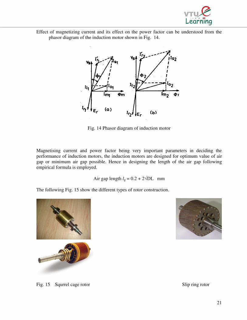
Effect of magnetizing current and its effect on the power factor can be understood from the
phasor diagram of the induction motor shown in Fig. 14.
Fig. 14 Phasor diagram of induction motor
Magnetising current and power factor being very important parameters in deciding the
performance of induction motors, the induction motors are designed for optimum value of air
gap or minimum air gap possible. Hence in designing the length of the air gap following
empirical formula is employed.
Air gap length lg = 0.2 + 2√DL mm
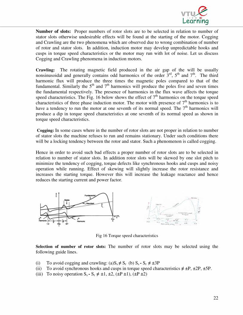
The following Fig. 15 show the different types of rotor construction.
Fig. 15 Squrrel cage rotor Slip ring rotor
22
Number of slots: Proper numbers of rotor slots are to be selected in relation to number of
stator slots otherwise undesirable effects will be found at the starting of the motor. Cogging
and Crawling are the two phenomena which are observed due to wrong combination of number
of rotor and stator slots. In addition, induction motor may develop unpredictable hooks and
cusps in torque speed characteristics or the motor may run with lot of noise. Let us discuss
Cogging and Crawling phenomena in induction motors.
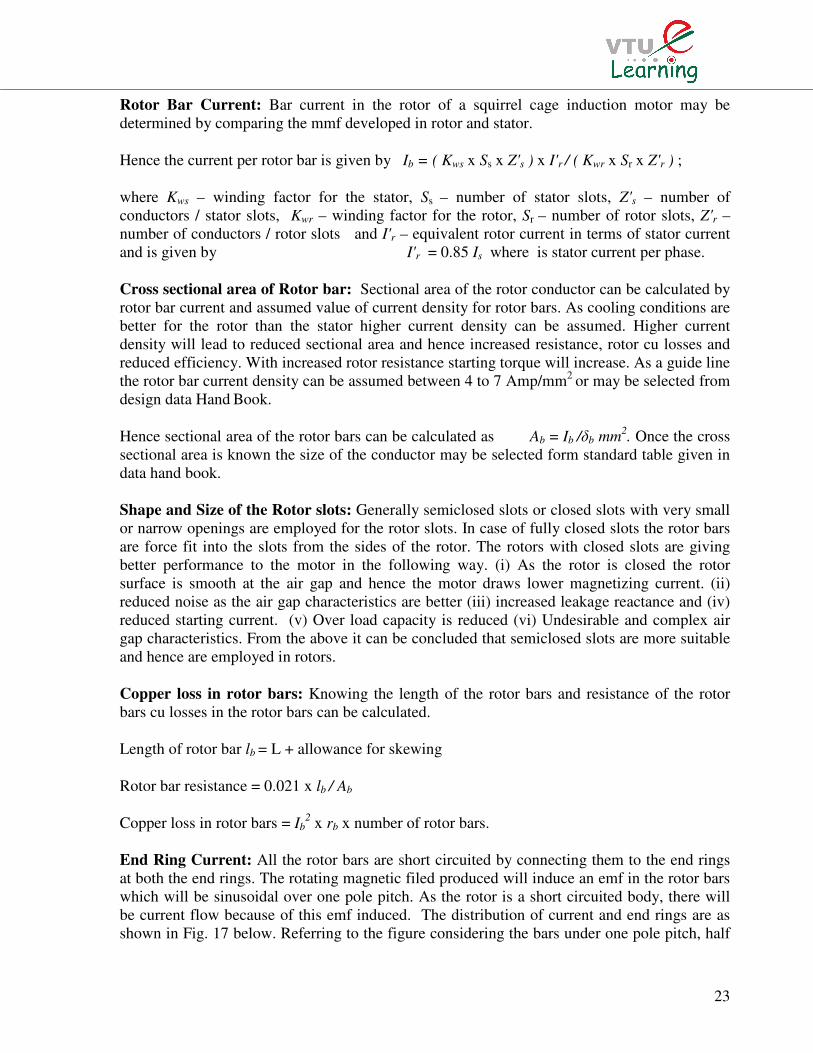
Crawling: The rotating magnetic field produced in the air gap of the will be usually
nonsinusoidal and generally contains odd harmonics of the order 3rd
, 5th
and 7th
. The third
harmonic flux will produce the three times the magnetic poles compared to that of the
fundamental. Similarly the 5th
and 7th
harmonics will produce the poles five and seven times
the fundamental respectively. The presence of harmonics in the flux wave affects the torque
speed characteristics. The Fig. 16 below shows the effect of 7th
harmonics on the torque speed
characteristics of three phase induction motor. The motor with presence of 7th
harmonics is to
have a tendency to run the motor at one seventh of its normal speed. The 7th
harmonics will
produce a dip in torque speed characteristics at one seventh of its normal speed as shown in
torque speed characteristics.
Cogging: In some cases where in the number of rotor slots are not proper in relation to number
of stator slots the machine refuses to run and remains stationary. Under such conditions there
will be a locking tendency between the rotor and stator. Such a phenomenon is called cogging.
Hence in order to avoid such bad effects a proper number of rotor slots are to be selected in
relation to number of stator slots. In addition rotor slots will be skewed by one slot pitch to
minimize the tendency of cogging, torque defects like synchronous hooks and cusps and noisy
operation while running. Effect of skewing will slightly increase the rotor resistance and
increases the starting torque. However this will increase the leakage reactance and hence
reduces the starting current and power factor.
Fig 16 Torque speed characteristics
Selection of number of rotor slots: The number of rotor slots may be selected using the
following guide lines.
(i) To avoid cogging and crawling: (a)Ss ≠ Sr (b) Ss - Sr ≠ ±3P
(ii) To avoid synchronous hooks and cusps in torque speed characteristics ≠ ±P, ±2P, ±5P.
(iii) To noisy operation Ss - Sr ≠ ±1, ±2, (±P ±1), (±P ±2)
23
Rotor Bar Current: Bar current in the rotor of a squirrel cage induction motor may be
determined by comparing the mmf developed in rotor and stator.
Hence the current per rotor bar is given by Ib = ( Kws x Ss x Z's ) x I'r / ( Kwr x Sr x Z'r ) ;
where Kws – winding factor for the stator, Ss – number of stator slots, Z's – number of
conductors / stator slots, Kwr – winding factor for the rotor, Sr – number of rotor slots, Z'r –
number of conductors / rotor slots and I'r – equivalent rotor current in terms of stator current
and is given by I'r = 0.85 Is where is stator current per phase.
Cross sectional area of Rotor bar: Sectional area of the rotor conductor can be calculated by
rotor bar current and assumed value of current density for rotor bars. As cooling conditions are
better for the rotor than the stator higher current density can be assumed. Higher current
density will lead to reduced sectional area and hence increased resistance, rotor cu losses and
reduced efficiency. With increased rotor resistance starting torque will increase. As a guide line
the rotor bar current density can be assumed between 4 to 7 Amp/mm2
or may be selected from
design data Hand Book.
Hence sectional area of the rotor bars can be calculated as Ab = Ib /δb mm2. Once the cross
sectional area is known the size of the conductor may be selected form standard table given in
data hand book.
Shape and Size of the Rotor slots: Generally semiclosed slots or closed slots with very small
or narrow openings are employed for the rotor slots. In case of fully closed slots the rotor bars
are force fit into the slots from the sides of the rotor. The rotors with closed slots are giving
better performance to the motor in the following way. (i) As the rotor is closed the rotor
surface is smooth at the air gap and hence the motor draws lower magnetizing current. (ii)
reduced noise as the air gap characteristics are better (iii) increased leakage reactance and (iv)
reduced starting current. (v) Over load capacity is reduced (vi) Undesirable and complex air
gap characteristics. From the above it can be concluded that semiclosed slots are more suitable
and hence are employed in rotors.
Copper loss in rotor bars: Knowing the length of the rotor bars and resistance of the rotor
bars cu losses in the rotor bars can be calculated.
Length of rotor bar lb = L + allowance for skewing
Rotor bar resistance = 0.021 x lb / Ab
Copper loss in rotor bars = Ib2 x rb x number of rotor bars.
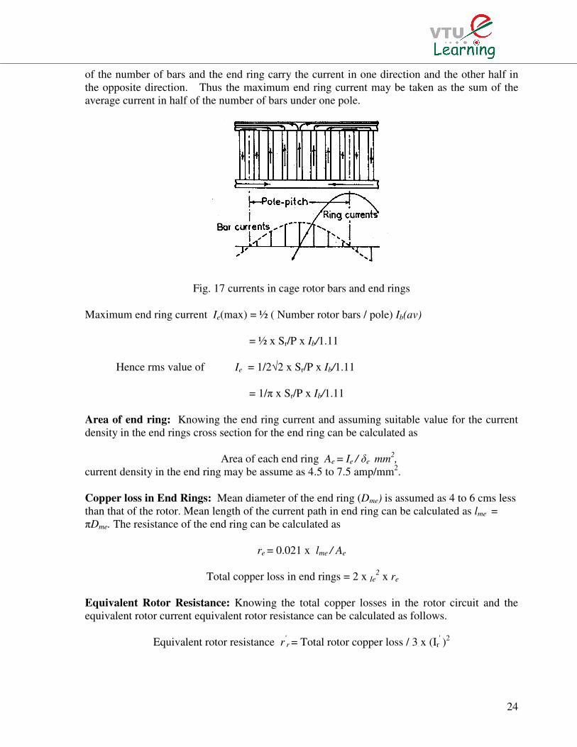
End Ring Current: All the rotor bars are short circuited by connecting them to the end rings
at both the end rings. The rotating magnetic filed produced will induce an emf in the rotor bars
which will be sinusoidal over one pole pitch. As the rotor is a short circuited body, there will
be current flow because of this emf induced. The distribution of current and end rings are as
shown in Fig. 17 below. Referring to the figure considering the bars under one pole pitch, half
24
of the number of bars and the end ring carry the current in one direction and the other half in
the opposite direction. Thus the maximum end ring current may be taken as the sum of the
average current in half of the number of bars under one pole.
Fig. 17 currents in cage rotor bars and end rings
Maximum end ring current Ie(max) = ½ ( Number rotor bars / pole) Ib(av)
= ½ x Sr/P x Ib/1.11
Hence rms value of Ie = 1/2√2 x Sr/P x Ib/1.11
= 1/π x Sr/P x Ib/1.11
Area of end ring: Knowing the end ring current and assuming suitable value for the current
density in the end rings cross section for the end ring can be calculated as
Area of each end ring Ae = Ie / δe mm2,
current density in the end ring may be assume as 4.5 to 7.5 amp/mm2.
Copper loss in End Rings: Mean diameter of the end ring (Dme) is assumed as 4 to 6 cms less
than that of the rotor. Mean length of the current path in end ring can be calculated as lme =
πDme. The resistance of the end ring can be calculated as
re = 0.021 x lme / Ae
Total copper loss in end rings = 2 x Ie2 x re
Equivalent Rotor Resistance: Knowing the total copper losses in the rotor circuit and the
equivalent rotor current equivalent rotor resistance can be calculated as follows.
Equivalent rotor resistance r'r = Total rotor copper loss / 3 x (Ir
' )2
25
Design of wound Rotor: These are the types of induction motors where in rotor also carries
distributed star connected 3 phase winding. At one end of the rotor there are three slip rings
mounted on the shaft. Three ends of the winding are connected to the slip rings. External
resistances can be connected to these slip rings at starting, which will be inserted in series with
the windings which will help in increasing the torque at starting. Such type of induction motors
are employed where high starting torque is required.
Number of rotor slots: As mentioned earlier the number of rotor slots should never be equal
to number of stator slots. Generally for wound rotor motors a suitable value is assumed for
number of rotor slots per pole per phase, and then total number of rotor slots are calculated. So
selected number of slots should be such that tooth width must satisfy the flux density
limitation. Semiclosed slots are used for rotor slots.
Number of rotor Turns: Number of rotor turns are decided based on the safety consideration
of the personal working with the induction motors. The volatge between the slip rings on open
circuit must be limited to safety values. In general the voltage between the slip rings for low
and medium voltage machines must be limited to 400 volts. For motors with higher voltage
ratings and large size motors this voltage must be limited to 1000 volts. Based on the assumed
voltage between the slip rings comparing the induced voltage ratio in stator and rotor the
number of turns on rotor winding can be calculated.
Voltage ratio Er/ Es = (Kwr x Tr) / (Kws x Ts )
Hence rotor turns per phase Tr = (Er/Es) (Kws/Kwr) Ts
Er = open circuit rotor voltage/phase
Es = stator voltage /phase
Kws = winding factor for stator
Kwr = winding factor for rotor
Ts = Number of stator turns/phase
Rotor Current
Rotor current can be calculated by comparing the amp-cond on stator and rotor
Ir = (Kws x Ss x Z's ) x I'r / ( Kwr x Sr x Z'r ) ;
Kws – winding factor for the stator,
Ss – number of stator slots,
Z's – number of conductors / stator slots,
Kwr – winding factor for the rotor,
Sr – number of rotor slots,
Z'r – number of conductors / rotor slots and
I'r – equivalent rotor current in terms of stator current
I'r = 0.85 Is where Is is stator current per phase.
26
Area of Rotor Conductor: Area of rotor conductor can be calculated based on the
assumed value for the current density in rotor conductor and calculated rotor current.
Current density rotor conductor can be assumed between 4 to 6 Amp/mm2
Ar = Ir / δr mm2
Ar < 5mm2 use circular conductor, else rectangular conductor, for rectangular
conductor width to thickness ratio = 2.5 to 4. Then the standard conductor size can be
selected similar to that of stator conductor.
Size of Rotor slot: Mostly Semi closed rectangular slots employed for the rotors.
Based on conductor size, number conductors per slot and arrangement of conductors
similar to that of stator, dimension of rotor slots can be estimated. Size of the slot must
be such that the ratio of depth to width of slot must be between 3 and 4.
Total copper loss: Length of the mean Turn can be calculated from the empirical
formula lmt = 2L + 2.3 τp + 0.08 m
Resistance of rotor winding is given by Rr = (0.021 x lmt x Tr ) / Ar
Total copper loss = 3 Ir2 Rr Watts
Flux density in rotor tooth: It is required that the dimension of the slot is alright from
the flux density consideration. Flux density has to be calculated at 1/3rd
height from the
root of the teeth. This flux density has to be limited to 1.8 Tesla. If not the width of the
tooth has to be increased and width of the slot has to be reduced such that the above
flux density limitation is satisfied. The flux density in rotor can be calculated by as
shown below.
Diameter at 1/3rd height Dr' = D - 2/3 x htr x 2
Slot pitch at 1/3rd height = τ'r = π x Dr' /Sr
Tooth width at this section = b'tr = τ'sr – bsr
Area of one rotor tooth = a'tr = b'tr x li
Iron length of the rotor li = (L- wd x nd)ki, ki = iron space factor
Area of all the rotor tooth / pole A'tr = b't x li x Sr /P
Mean flux density in rotor teeth B'tr = Φ / A'tr
Maximum flux density in the rotor teeth < 1.5 times B'tr
Depth of stator core below the slots: Below rotor slots there is certain solid portion
which is called depth of the core below slots. This depth is calculated based on the flux
27
density and flux in the rotor core. Flux density in the rotor core can be assumed to be
between 1.2 to 1.4 Tesla. Then depth of the core can be found as follows.
Flux in the rotor core section Φc = ½ Φ
Area of stator core Acr = Φ/2Bcr
Area of stator core Acr = Li x dcr
Hence, depth of the core dcr = Acr / Li
Inner diameter of the rotor can be calculated as follows
Inner diameter of rotor = D - 2lg - 2htr – 2 dcr
Ex.1. During the stator design of a 3 phase, 30 kW, 400volts, 6 pole, 50Hz,squirrel
cage induction motor following data has been obtained. Gross length of the stator =
0.17 m, Internal diameter of stator = 0.33 m, Number of stator slots = 45, Number of
conductors per slot = 12. Based on the above design data design a suitable rotor.
Soln: (i) Diameter of the rotor
Length of the air gap lg = 0.2 + 2 √DL mm
= 0.2 + 2 √0.33 x 0.17 mm
= 0.67 mm
Outer diameter of rotor Dr = D - 2 lg
= 0.33 – 2 x 0.67 x 10-3
= 0.328 m
(ii) Number of rotor slots
(a) Ss > Sr
(b) To avoid cogging and crawling: Sr ≠ Ss, Ss - Sr ≠ ±3P
Sr ≠ 45, Ss - Sr ≠ ± 3P → 45 – 18 ≠ 27,
(c) To avoid synchronous hooks and cusps in torque speed characteristics Ss - Sr ≠ ±P,
±2P, ±5P
Ss - Sr ≠ (45 – 6), (45 – 12), (45 – 03) ≠ 39, 33, 15
To avoid noisy operation Ss - Sr ≠ ±1, ±2, (±P ±1), (±P ±2)
Ss - Sr ≠ (45 – 1) , (45 – 2), (45 – 7), (45 – 8)
Considering all the combination above Sr = 42
Rotor slot pitch = πDr / Sr = π x 32.8 / 42 = 2.45 cm (quite satisfactory)
(iii) Rotor bar current
28
Assuming star – delta connection for stator winding
Vph = 400 volts
Assuming η = 88 % and p.f = 0.86
Motor input = 30/0.88 = 30.1 kW
Full load stator current = input / 3 vph cosΦ
= 30.1 x 10³/ 3 x 440 x 0.86
= 33 amps
I'r = 0.85 Is = 0.85 x 33 = 28 amps
Assuming Kws = 0.955 & No. of rotor cond/slot = 1
Ib = ( Kws x Ss x Z's ) x I'r / ( Kwr x Sr x Z'r )
= (0.955 x 45 x 12) x 28 /( 1 x 42 x 1)
343.8 amps
(iv) Size of rotor bar and slot
Assuming the current density in rotor bars = 6.0 amps/mm2
Ar = Ir / δr mm2
Ar = 343.8/ 6.0
= 57. 3 mm2
Selecting rectangular standard conductor available
Area of conductor = 57.6 mm2
Hence standard conductor size = 13 mm x 4.5 mm
Size of rotor slot to fit the above cond = 13.5 mm x 5 mm
(v) Resistance of rotor bar
Length of rotor bar lb = L + allowance for skewing + allowance between end rings and
rotor core
lb = 0.17 +0.05 =0.22 m
29
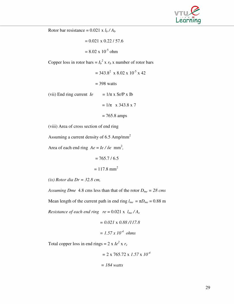
Rotor bar resistance = 0.021 x lb / Ab
= 0.021 x 0.22 / 57.6
= 8.02 x 10⁻⁵
ohm
Copper loss in rotor bars = Ib2 x rb x number of rotor bars
= 343.82 x 8.02 x 10
-5 x 42
= 398 watts
(vii) End ring current Ie = 1/π x Sr/P x Ib
= 1/π x 343.8 x 7
= 765.8 amps
(viii) Area of cross section of end ring
Assuming a current density of 6.5 Amp/mm2
Area of each end ring Ae = Ie / δe mm2,
= 765.7 / 6.5
= 117.8 mm2
(ix) Rotor dia Dr = 32.8 cm,
Assuming Dme 4.8 cms less than that of the rotor Dme = 28 cms
Mean length of the current path in end ring lme = πDme = 0.88 m
Resistance of each end ring re = 0.021 x lme / Ae
= 0.021 x 0.88 /117.8
= 1.57 x 10⁻⁴
ohms
Total copper loss in end rings = 2 x Ie2 x re
= 2 x 765.72 x 1.57 x 10-4
= 184 watts
30
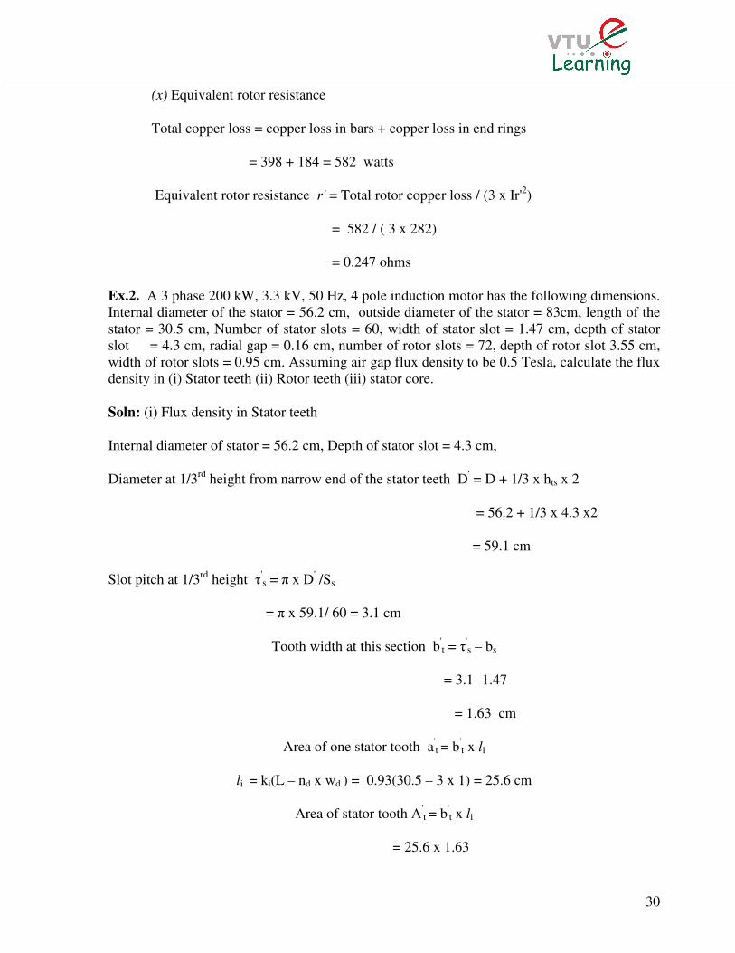
(x) Equivalent rotor resistance
Total copper loss = copper loss in bars + copper loss in end rings
= 398 + 184 = 582 watts
Equivalent rotor resistance r' = Total rotor copper loss / (3 x Ir'2)
= 582 / ( 3 x 282)
= 0.247 ohms
Ex.2. A 3 phase 200 kW, 3.3 kV, 50 Hz, 4 pole induction motor has the following dimensions.
Internal diameter of the stator = 56.2 cm, outside diameter of the stator = 83cm, length of the
stator = 30.5 cm, Number of stator slots = 60, width of stator slot = 1.47 cm, depth of stator
slot = 4.3 cm, radial gap = 0.16 cm, number of rotor slots = 72, depth of rotor slot 3.55 cm,
width of rotor slots = 0.95 cm. Assuming air gap flux density to be 0.5 Tesla, calculate the flux
density in (i) Stator teeth (ii) Rotor teeth (iii) stator core.
Soln: (i) Flux density in Stator teeth
Internal diameter of stator = 56.2 cm, Depth of stator slot = 4.3 cm,
Diameter at 1/3rd
height from narrow end of the stator teeth D' = D + 1/3 x hts x 2
= 56.2 + 1/3 x 4.3 x2
= 59.1 cm
Slot pitch at 1/3rd
height τ's = π x D' /Ss
= π x 59.1/ 60 = 3.1 cm
Tooth width at this section b't = τ's – bs
= 3.1 -1.47
= 1.63 cm
Area of one stator tooth a't = b
't x li
li = ki(L – nd x wd ) = 0.93(30.5 – 3 x 1) = 25.6 cm
Area of stator tooth A't = b
't x li
= 25.6 x 1.63
31
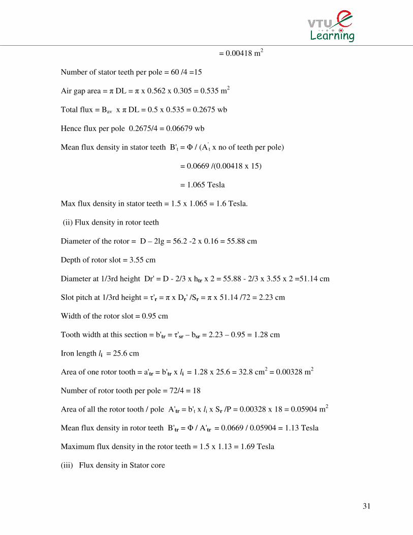
= 0.00418 m2
Number of stator teeth per pole = 60 /4 =15
Air gap area = π DL = π x 0.562 x 0.305 = 0.535 m2
Total flux = Bav x π DL = 0.5 x 0.535 = 0.2675 wb
Hence flux per pole 0.2675/4 = 0.06679 wb
Mean flux density in stator teeth B't = Φ / (A't x no of teeth per pole)
= 0.0669 /(0.00418 x 15)
= 1.065 Tesla
Max flux density in stator teeth = 1.5 x 1.065 = 1.6 Tesla.
(ii) Flux density in rotor teeth
Diameter of the rotor = D – 2lg = 56.2 -2 x 0.16 = 55.88 cm
Depth of rotor slot = 3.55 cm
Diameter at 1/3rd height Dr' = D - 2/3 x htr x 2 = 55.88 - 2/3 x 3.55 x 2 =51.14 cm
Slot pitch at 1/3rd height = τ'r = π x Dr' /Sr = π x 51.14 /72 = 2.23 cm
Width of the rotor slot = 0.95 cm
Tooth width at this section = b'tr = τ'sr – bsr = 2.23 – 0.95 = 1.28 cm
Iron length li = 25.6 cm
Area of one rotor tooth = a'tr = b'tr x li = 1.28 x 25.6 = 32.8 cm2 = 0.00328 m
2
Number of rotor tooth per pole = 72/4 = 18
Area of all the rotor tooth / pole A'tr = b't x li x Sr /P = 0.00328 x 18 = 0.05904 m2
Mean flux density in rotor teeth B'tr = Φ / A'tr = 0.0669 / 0.05904 = 1.13 Tesla
Maximum flux density in the rotor teeth = 1.5 x 1.13 = 1.69 Tesla
(iii) Flux density in Stator core
32
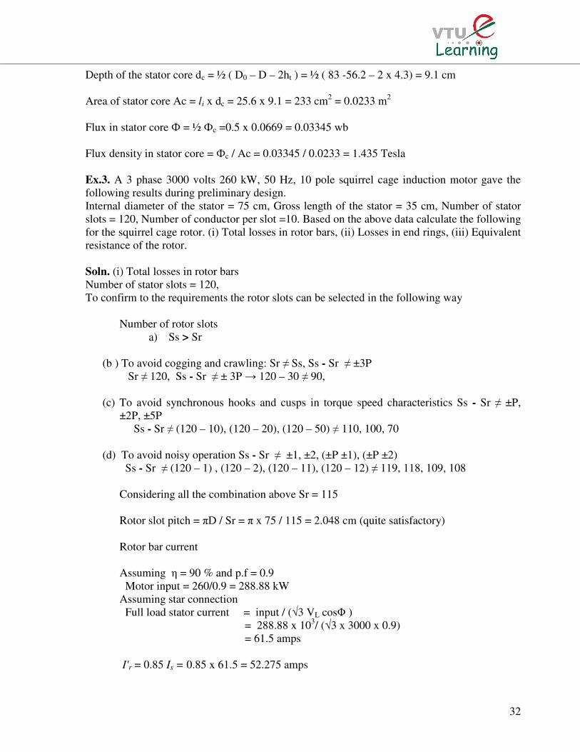
Depth of the stator core dc = ½ ( D0 – D – 2ht ) = ½ ( 83 -56.2 – 2 x 4.3) = 9.1 cm
Area of stator core Ac = li x dc = 25.6 x 9.1 = 233 cm2 = 0.0233 m
2
Flux in stator core Ф = ½ Фc =0.5 x 0.0669 = 0.03345 wb
Flux density in stator core = Фc / Ac = 0.03345 / 0.0233 = 1.435 Tesla
Ex.3. A 3 phase 3000 volts 260 kW, 50 Hz, 10 pole squirrel cage induction motor gave the
following results during preliminary design.
Internal diameter of the stator = 75 cm, Gross length of the stator = 35 cm, Number of stator
slots = 120, Number of conductor per slot =10. Based on the above data calculate the following
for the squirrel cage rotor. (i) Total losses in rotor bars, (ii) Losses in end rings, (iii) Equivalent
resistance of the rotor.
Soln. (i) Total losses in rotor bars
Number of stator slots = 120,
To confirm to the requirements the rotor slots can be selected in the following way
Number of rotor slots
a) Ss > Sr
(b ) To avoid cogging and crawling: Sr ≠ Ss, Ss - Sr ≠ ±3P
Sr ≠ 120, Ss - Sr ≠ ± 3P → 120 – 30 ≠ 90,
(c) To avoid synchronous hooks and cusps in torque speed characteristics Ss - Sr ≠ ±P,
±2P, ±5P
Ss - Sr ≠ (120 – 10), (120 – 20), (120 – 50) ≠ 110, 100, 70
(d) To avoid noisy operation Ss - Sr ≠ ±1, ±2, (±P ±1), (±P ±2)
Ss - Sr ≠ (120 – 1) , (120 – 2), (120 – 11), (120 – 12) ≠ 119, 118, 109, 108
Considering all the combination above Sr = 115
Rotor slot pitch = πD / Sr = π x 75 / 115 = 2.048 cm (quite satisfactory)
Rotor bar current
Assuming η = 90 % and p.f = 0.9
Motor input = 260/0.9 = 288.88 kW
Assuming star connection
Full load stator current = input / (√3 VL cosΦ )
= 288.88 x 10³/ (√3 x 3000 x 0.9)
= 61.5 amps
I'r = 0.85 Is = 0.85 x 61.5 = 52.275 amps
33
Assuming Kws = 0.955 & No. of rotor cond/slot = 1
Ib = ( Kws x Ss x Z's ) x I'r / ( Kwr x Sr x Z'r )
= (0.955 x 120 x 10) x 52.275 /( 1 x 115 x 1)
= 521 amps
Area of rotor bar
Assuming the current density in rotor bars = 6.5 amps/mm2
Ab = Ib / δb mm2
Ab = 521/ 6.5
= 80.2 mm2
Length of rotor bar lb = L + allowance for skewing + allowance between end rings and
rotor core
lb = 0.35 +0.05 =0.4 m
Rotor bar resistance = 0.021 x lb / Ab
= 0.021 x 0.4 / 80.2
= 1.05 x 10⁻⁴
ohm
Copper loss in rotor bars = Ib2 x rb x number of rotor bars
= 5212 x 1.05 x 10
-4 x 115
= 3278 watts
(ii) Losses in end rings
End ring current Ie = 1/π x Sr/P x Ib
= 1/π x (115/10) x 521
= 1906 amps
Area of cross section of end ring
34
Assuming a current density of 6.5 Amp/mm2
Area of each end ring Ae = Ie / δe mm2,
= 1906/6.5
= 293.2 mm2
Air gap length lg = 0.2 + 2√DL
= 0.2 +2√0.75 x 0.35
= 1.22 mm
Rotor diameter Dr = D -2 lg
= 75 – 0.122
= 74.878 cm
Rotor dia Dr = 74.878 cm,
Assuming Dme 6.878 cms less than that of the rotor Dme = 68 cms
Mean length of the current path in end ring lme = πDme = 2.136 m
Resistance of each end ring re = 0.021 x lme / Ae
= 0.021 x 2.136 /293.2
= 1.529 x 10⁻⁴
ohms
Total copper loss in end rings = 2 x Ie2 x re
= 2 x 19062 x 1.529 x 10
-4
= 1111.55 watts
(iii) Equivalent rotor resistance
Total copper losses in the rotor = Copper loss in bars + copper loss in end rings
= 3278 +1111.55
= 4389.55 watts
35
Equivalent Rotor resistance = Rotor cu loss / ( 3 I’ r
2 )
= 4389.55/(3 x 52.2752)
= 0.535 ohm
Ex.4. Following design data have been obtained during the preliminary design of a 3 phase,
850 kW, 6.6 kV, 50 Hz, 12 pole slip ring induction motor. Gross length of stator core = 45 cm,
internal diameter of the stator core = 122 cm, number of stator slots = 144, Number of
conductors per slot = 10. For the above stator data design a wound rotor for the motor.
Soln : (i) Diameter of the rotor
Length of the air gap lg = 0.2 + 2 √DL mm
= 0.2 + 2 √1.22 x 0.45 mm
= 1.68 mm
Outer diameter of rotor Dr = D - 2 lg
= 1.22 – 2 x 1.68 x 10-3
= 1.217 m
(ii) Number of rotor slots : Considering all the factors for selection of number of rotor slots,
and selecting fractional slot winding, assuming number of rotor slots per pole per phase as 3½
Total number of rotor slots = 3.5 x 12 x 3 = 126
Rotor slot pitch = π Dr / Sr
= π x 1.217 / 126
= 0.0303 m (quite satisfactory)
(iii) Number of rotor turns: For this motor the voltage between slip rings must be less than
1000 volts. Assume the voltage between slip rings as 600 volts.
Assuming star connection for stator winding Es = 6600/√3 = 3810 volts, Assuming Kws = Kwr
=1
Rotor winding will always be star connected
Total number of stator conductors = 144 x 10
Total number of stator turns per phase = 144 x 10 / (3 x 2) = 240
Rotor turns per phase Tr = (Er/Es) x (Kws/Kwr) Ts
= 600/√3 x 1 x 240 / 3810
= 22 turns
Rotor conductors per phase = 44,
Number of slots per phase = 126/3 = 42,
36
Therefore number of conductors per slot = 1.
Final rotor turns/phase = number of conductors per phase / 2 = 42/ 2 = 21
(iv) Rotor current
As the motor is of 850 kW, efficiency will be high, assuming an efficiency of 92% and cosФ =
0.91
Input to the motor = 850/0.92 = 924 kW,
Full load stator current per phase Is = 924 x 103 / (3 x 3180 x 0.91)
= 88.8 amps
Equivalent rotor current Ir' = 0.85 Is = 0.85 x 88.8 =75.5 amps
Ir = (Kws x Ss x Z's ) x I'r / ( Kwr x Sr x Z'r ) ;
= (144 x 10 x 75.5) / 126 x 1
= 863 amps
(v) Size of rotor conductors
Assuming a current density of 5 Amp/ mm2 for the rotor conductors ,
Cross sectional area of the rotor conductor = 863/5 = 172.6 mm2
Size of the rotor conductors is too large and this conductor can not be used as it is and hence
has to be stranded. Stranding the conductors into 4 rectangular strips of each area 43.1 mm2, in
parallel,
Standard size of the rectangular strip selected = 11 mm x 4 mm,
Thus sectional area of the rectangular conductor 43.1 x 4 = 172.4 mm2
Size of the rectangular conductor with insulation = 11.5 mm x 4.5 mm
(vi) Size of the rotor slot
Four strips of the rectangular conductor are arranged as 2 strips widthwise and 2 strips
depthwise, with this arrangement the size of the slot can be estimated as follows
(a) width of the slot
37
Space occupied by the conductor 2 x4.5 9.0 mm
Slot liner 2 x 1.5 3.0 mm
Clearance 1.0 mm
Total width of the slot 13.0 mm
(b) Depth of the slot
Space occupied by the conductor 2 x11.5 23.0 mm
Slot liner 3 x 1.5 4.5 mm
Wedge 3.5 mm
Lip 1.0 mm
Clearance 1.0 mm
Total depth of the slot 34.0 mm
Thus size of the rotor slot = 13 mm x 34 mm
(vi) Resistance and copper losses
Length of the mean Turn lmt = 2L + 2.3 τp + 0.08 m
lmt = 2x 0.45 + 2.3 ( π x 1.22 / 12 ) + 0.08 m
= 1.72 m
Resistance of rotor winding is given by Rr = (0.021 x lmt x Tr ) / Ar
= (0.021 x 1.72 x 21) / 172.4
= 0.0044 ohm
Total copper loss = 3 Ir2 Rr Watts
= 3 x 8632 x 0.0044
= 9831 watts
Performance Evaluation:
Based on the design data of the stator and rotor of an induction motor, performance of the
machine has to be evaluated. The parameters for performance evaluation are iron losses, no
load current, no load power factor, leakage reactance etc. Based on the values of these
parameters design values of stator and rotor can be justified.
38
Iron losses: Iron losses are occurring in all the iron parts due to the varying magnetic field of
the machine. Iron loss has two components, hysteresis and eddy current losses occurring in the
iron parts depend upon the frequency of the applied voltage. The frequency of the induced
voltage in rotor is equal to the slip frequency which is very low and hence the iron losses
occurring in the rotor is negligibly small. Hence the iron losses occurring in the induction
motor is mainly due to the losses in the stator alone. Iron losses occurring in the stator can be
computed as given below.
(a) Losses in stator teeth:
The following steps explain the calculation of iron loss in the stator teeth
(i) Calculate the area of cross section of stator tooth based on the width of the tooth at
1/3rd
height and iron length of the core as A'ts= b'ts x li m2
(ii) Calculate the volume all the teeth in stator Vts = A'ts x hts x Ss m3
(iii) Compute the weight of all the teeth based on volume and density of the material as
Wts = Vts x density. ( density of the material can be found in DDH) (7.8 x 10⁻³
kg/m3)
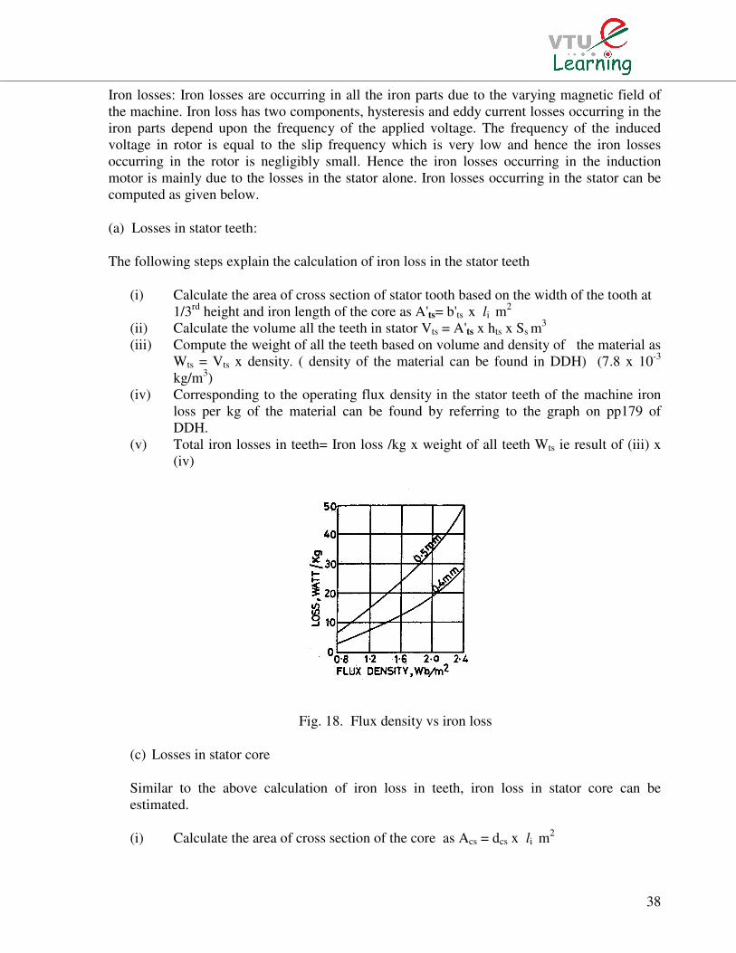
(iv) Corresponding to the operating flux density in the stator teeth of the machine iron
loss per kg of the material can be found by referring to the graph on pp179 of
DDH.
(v) Total iron losses in teeth= Iron loss /kg x weight of all teeth Wts ie result of (iii) x
(iv)
Fig. 18. Flux density vs iron loss
(c) Losses in stator core
Similar to the above calculation of iron loss in teeth, iron loss in stator core can be
estimated.
(i) Calculate the area of cross section of the core as Acs = dcs x li m2
39
(ii) Calculate the mean diameter of the stator core below the slots as Dmcs= D + 2 hts +
dcs m
(iii) Compute the volume of stator core as Vcs = Acs x π Dmcs m3
(iv) Calculate the weight of the stator core as Wcs = Vcs x density
(v) Corresponding to the operating flux density in the stator core of the machine iron
loss per kg of the material can be found by referring to the graph on pp 179 of
DDH.
(vi) Total iron losses in core = Iron loss /kg x weight of core Wcs ie result of (iv) x (v)
Total iron losses in induction motor = Iron loss in stator core + iron losses in stator teeth.
In addition friction and windage loss can be taken into account by assuming it as 1- 2 % of
the out put of the motor.
Hence total no load losses = Total iron losses + Friction and windage loss.
No load current: As seen from Fig 14, the no load current of an induction motor has two
components magnetizing component, Im and iron loss component, Iw. Phase relation
between these currents is shown in Fig. 14.
Thus the no load current I0 = √(Im)2 + (Iw)
2 amps
Magnetising current: Magnetising current of an induction motor is responsible for
producing the required amount of flux in the different parts of the machine. Hence this
current can be calculated from all the magnetic circuit of the machine. The ampere turns for
all the magnetic circuit such as stator core, stator teeth, air gap, rotor core and rotor teeth
gives the total ampere turns required for the magnetic circuit. The details of the magnetic
circuit calculations are studied in magnetic circuit calculations. Based on the total ampere
turns of the magnetic circuit the magnetizing current can be calculated as
Magnetising current Im= p AT30 / (1.17 kw Tph )
where p – no of pairs of poles, AT30 – Total ampere turns of the magnetic circuit at 300
from the centre of the pole, Tph – Number of stator turns per phase.
Iron loss component of current: This component of current is responsible for supplying the
iron losses in the magnetic circuit. Hence this component can be calculated from no load
losses and applied voltage.
Iron loss component of current Iw= Total no load losses / ( 3 x phase voltage)
No load Power Factor: No load power factor of an induction motor is very poor. As the
load on the machine increases the power factor improves. No load power factor can be
calculated knowing the components of no load current.
No load power factor cosΦ0 = Iw / I0
40
Ex. While designing the stator of a 3 phase 10 kW, 400 volts, 50 Hz, 4 pole, wound rotor
induction motor, following data are obtained.
Internal diameter of stator = 0.19 m
Gross length = 0.125 m
Number of stator slots = 36
Number of conductors/slot = 38
Dimension of stator slot = 1.1 cm x 3.5 cm
Depth of the stator core = 3 cm
Number of rotor slots = 30
Dimension of the rotor slot = 0.7 cm x 3.0 cm
Depth of rotor core = 3.0 cm
Carter’s coefficient for the air gap = 1.33
Based on the above data, calculate the following performance data for this motor.
(i) Flux per pole (ii) Iron losses (iii) Active component of no load current (iv) No load current
(v) No load power factor
Soln. (i) Flux per pole
Total number of stator conductors = 36 x 38 = 1368
Stator turns per phase Tph = 1368 /6 = 228
Assuming star delta connection for the motor Vph = 400 volts
Assuming Eph = Vph = 400 volts, winding factor = 0.955
Air gap flux per pole Φ = Eph/(4.44fTph kw)
= 400/( 4.44 x 50 x 228 x 0.955)
= 0.00827 wb
(ii) Iron losses
Total Iron losses = Iron losses in stator teeth + Iron losses in stator core
Iron losses in stator teeth:
For the given stator length assuming one ventilating duct of width 1cm and iron space factor of
0.95,
Li = (L – nd x wd)ki
= (0.125 -1 x 0.01)0.95
= 0.109 m
Diameter at 1/3rd
height, D' = D + 1/3 x hts x 2 = 0.19 + 1/3 x 0.035 x 2 = 0.213 m
Slot pitch at 1/3rd
height = τ's = π x D' /Ss = π x 0.213 /36 = 0.0186 m
Tooth width at this section = b't = τ's – bs = 0.0186 – 0.011 = 0.0076 m
Area of the stator tooth per pole A't = b
't x li x number of teeth per pole
= b't x li x Ss /p = 0.0076 x 0.109 x 36/4
41
= 0.00746 m2
Mean flux density in stator teeth B't = Φ / A't = 0.00827/ 0.00746 = 1.10 9 Tesla
Maximum flux density in stator tooth =1.5 x 1.109 = 1.66 Tesla
Volume of all the stator teeth = b't x li x height of teeth x number of teeth
= 0.0076 x 0.109 x 0.035 x 36
= 0.001044 m3
Weight of all the teeth = volume x density
Assuming a density of 7.8 x 10³
kg/ m3
Weight of all the teeth = 0.001044 x 7.8 x 103
= 8.14 kg
Total iron losses in the stator teeth = Total weight x loss/kg
Iron loss in the material at a flux density of 1.66 Tesla from graph PP-22 of DDH loss/kg = 23
w/kg
Total iron losses in the stator teeth = 23 x 8.14 = 187.22 watts
Iron losses in stator core : Sectional area of the stator core = li x dc = 0.109 x 0.03
= 0.00327 m2
Mean diameter of the stator core below the slots = 0.19 + 2 x 0.035 + 0.03 = 0.29 m
Volume of the stator core = π x D x Acs = π x 0.29 x 0.00327 = 0.002979 m3
Weight of the stator core = 0.002979 x 7.8 x 103
= 23.23 kg
Flux density in stator core = Φc / Acs = 0.00827/(2 x 0.00327) = 1.264 Tesla
At this flux density iron loss/kg = 17 watts/kg
Iron losses in the stator core = 17 x 23.23 = 394.91watts
Total iron losses in the stator = 187.22 + 394.91= 582.13 watts
(iii) Active component of no load current
Assuming the friction and windage losses as 1% of output Friction and windage loss = 100 w
Total no load losses = 582.13 + 100 = 682.13 watts
Active component of no load current = Iron loss component of current
Iw= Total no load losses / ( 3 x phase voltage) = 682.13/( 3 x 400) = 0.568 amps
(iv) Magnetising current: In order to calculate the magnetizing current ampere turns required
for the various parts of the magnetic circuits are to be calculated.
(a) Ampere turns for the stator core:
Pole pitch at he mean diameter of the stator core = π x D/ P = π x 0.29/ 4 = 0.23 m
Length of the flux path in stator core = 1/3 x 0.23 = 0.077 m
Ampere turns per meter at a flux density of 1.264 Tesla from graph (PP-22 of DDH) 400
AT
Hence total ampere turns required for the stator core = 400 x 0.077 = 31
(b) Ampere turns for the stator teeth:
Length of the flux path in stator teeth = 0.035m
42
Flux density in stator teeth at 300 from the pole centre = 1.36 Bt
’
= 1.36 x 1.10 9 =1.508 Tesla
Ampere turns per meter at a flux density of 1.508 Tesla (from graph PP-22 of DDH) is
1000 AT
Hence total ampere turns for the stator teeth = 1000 x 0.035 = 35
(c) Ampere turns for the air gap:
Length of the air gap = 0.2 + 2√DL = 0.2 + 2√0.19 x 0.125 = 0.51 mm
Average flux density in the air gap = Φ/ (π x DL/ P) = 0.4696 Tesla
Carter’s coefficient for the air gap = 1.33
Air gap flux density at 300
from the centre of the pole Bg = 1.36 x Bav
= 1.36 x 0.4696
= 0.6387 Tesla
Hence Ampere turns for the air gap = 796000Bgkglg
ATg = 796000 x 0.687 x 1.33 x 0.51 x 10-3
= 371 AT
(d) Ampere turns for the rotor Teeth :
Diameter of the rotor = D -2lg =0.19 – 2 x 0.00051= 0.189 m
Diameter at 1/3rd
height form the narrow end of the teeth Dr’ = D – 2 x 2/3hrs
= 0.189 – 4/3 x 0.03
= 0.149 m
Slot pitch at 1/3rd
height = τ'r = π x Dr' /Sr = π x 0.149 /30 = 0.0156 m
Tooth width at this section = b'tr = τ'r – br = 0.0156 – 0.007 = 0.0086 m
Area of the stator tooth per pole A'tr = b
'tr x li x number of teeth per pole
= 0.0086 x 0.107 x 30/4 = 0.0069 m2
Flux density in rotor teeth at 300 from pole centre = 1.36 x 0.00827/0.0069 = 1.63 Tesla
Ampere turns/m at this flux density, from graph (PP-22 of DDH) = 2800
Length of flux path in rotor teeth = 0.03 m
Ampere turns for the rotor teeth 2800 x 0.03 = 84
(e) Ampere turns for the rotor core
Depth of the rotor core dcr = 3 cm
Area of the rotor core Acr = 0.03 x 0.107 = 0.00321 m2
Flux in the rotor = ½ x 0.00827 = 0.004135 wb
43
Flux density in the rotor core = 0.004135/0.00321= 1.29 Tesla
Ampere turns/m at this flux density, from graph (PP-22 of DDH) = 380
Mean diameter of the rotor core = Dr – 2 x hrs – dcr = 0.189 – 2 x 0.03 – 0.03 = 0.099 m
Pole pitch at this section = π x 0.099 /4 = 0.078 m
Length of the flux path in rotor core = 1/3 x 0.078 = 0.026 m
Total ampere turns for the rotor core = 380 x 0.026 =10
Total Ampere turns for the magnetic circuit = 31 + 35 + 371 + 84 +10 = 531 AT
Magnetising current Im = p(AT30) / (1.17 x Kw x Tph)
= 2 x 531 /( 1.17 x 0.955 x 228)
= 4.2 amps
(v) No load current
No load current per phase Io = √( Iw2 + Im
2)
= √( 0.562 + 4.2
2)
= 4.24 amps
(vi) No load power factor cosФ0 = Iw/I0 = 0.56 /4.24 = 0.132
References
1. A Course in Electrical Machine Design – A. K. Sawhney
2. Design of Electrical Machines – V. N. Mittle
3. Performance and Design of A C Machines – M G Say
4. Design and Testing of Electrical Machines – M. V. Deshapande
5. Electrical Machine Design Data Book – Shanmugsundaram and Palani
6. www.google.com and related websites
7. www.phasemotorparts.com
8. www.wikipedia.org
9. Krishna Vasudevan et. al. Electrical Machines II, Indian Institute of Technology,
Madras