inductive sensor telemetry 1 channel sensor signal ... · single channel sensor signal amplifier...
TRANSCRIPT

Inductive Sensor Telemetry1 Channel Sensor Signal Amplifiers
and Receivers
File: ...\SV_AW_KATALOG.cdr // 20170603
Page 2 ..................................................................ConfigurationPage 3 ... 28 .........................................................Sensor signal amplifierPage 29 ... 51 .........................................................Receiver

Single ChannelSensor Signal
Amplifier
Position(Differential transformer)
Contactless distance(µe transducer)
Inductivesupply and
transmission13,56 MHz
0 to ±10V
Piezo electric
PT100 RTD
Single ChannelReceiver
Remote shuntcalibration
Remote control(option)
Strain gagehalve brigde
Strain gagefull brigde
Thermocouple
PT100
NS
Coupling
Hall sensor
SpeedPickup
Trace ATrace BTrace 0
Incremental/Absolutconverter(option)
90 to 270V AC(9 to 36 V DC)
Digital interface(option) Ethernet
CANUSB
Shaft encoder interface (option)
Page 2
rotating
stationary
Configuration (modular inductive Telemetry)

Page 3
Sensor Signal Amplifier Type 2a
50,0
40,0 6,0
42,0
32,0
Ø5,0
4 x Ø4,5
+
+-
-R
R
RCal RG or RV
R
RUd
I+
Cal
GND
I-
UB
Rv1Rv2
* PCM version
28,7
1 kHz10 kHz40 kHz
0,020,010,003
85125150160
FMPCM16
-R
1 Channel FM/PCM TransmitterFor strain gage, PT100, thermocoupleSensitivity: 0.02 mV/V to 20 mV/VBandwidth: 0 (10) Hz to 50 kHzStrain gage brigde supply: 2.5 V (3.3 V*)Strain gage bridge resistance: 350 (120, 1000) WTransmission: inductive sensor telemetry FM, PCMIntegrated filterResolution: 14 Bits, 16 Bits*Zero point drift: 0.02, (0.01, 0.003 option)Remote shunt calibrationRemote gain, zero, auto zero with 16 Bit resolution (option)Additonal temperature channel (option)Enviromental temperature range: -25 to +85°C (125°C, 150°C)Max load: 5 000 g (depending on fixing)Type: SV_2a_<accuracy>_<temp>_<mod>_<bandwidth>_<rmc>

Sensor Signal Amplifier Type 2b (End of shaft, Cartridge, Turbine)Integrated Rotor Coil
Weight: about 10 g
+
+-
-R
R
RCal RG or RV
R
RUd
I+
Cal
GND
I-
UB
Rv1Rv2
4 mal Ø2,24,0
42,0
Ø16
,0
Ø 2
0,0
Ø 2
5,0
With integrated axial antenna
UB CalGNDRv1
I+I- Rv2Tk
* PCM versionPage 4
Sensor signalamplifier
Stator antenna(Pick up)
End of shaft
Weight: 15 g2Torque of inertia: 4.2E-7 kgm
1 kHz10 kHz40 kHz
0,020,010,003
85125150160
FMPCM16
-R
1 Channel FM/PCM TransmitterFor strain gage, PT100, thermocoupleSensitivity: 0.02 mV/V to 20 mV/VBandwidth: 0 (10) Hz to 50 kHzStrain gage brigde supply: 2.5 V (3.3 V*)Strain gage bridge resistance: 350 (120, 1000) WTransmission: inductive sensor telemetry FM, PCMIntegrated filterResolution: 14 Bits, 16 Bits*Zero point drift: 0.02, (0.01, 0.003 option)Remote shunt calibrationRemote gain, zero, auto zero with 16 Bit resolution (option)Additonal temperature channel (option)Enviromental temperature range: -25 to +85°C (125°C, 150°C)Max load: 50 000 g (depending on fixing)Type: SV_2b_<accuracy>_<temp>_<mod>_<bandwidth>_<rmc>_TC
TC

Sensor Signal Amplifier Type 2bx (End of shaft, Cartridge, Turbine)Integrated Rotor Coil
Weight: about 10 g
+
+-
-R
R
RCal RG or RV
R
RUd
I+
Cal
GND
I-
UB
Rv1Rv2
4 mal Ø2,24,0 Ø
16,0
Ø 2
0,0
Ø 2
5,0
With integrated axial antenna
UB CalGNDRv1
I+I- Rv2Tk
* PCM versionPage 5
Sensor signalamplifier
Stator antenna(Pick up)
End of shaftintegrated
Weight: 15 g2Torque of inertia: 4.2E-7 kgm
1 kHz10 kHz40 kHz
0,020,010,003
85125150160
FMPCM16
-R
1 Channel FM/PCM TransmitterFor strain gage, PT100, thermocoupleSensitivity: 0.02 mV/V to 20 mV/VBandwidth: 0 (10) Hz to 50 kHzStrain gage brigde supply: 2.5 V (3.3 V*)Strain gage bridge resistance: 350 (120, 1000) WTransmission: inductive sensor telemetry FM, PCMIntegrated filterResolution: 14 Bits, 16 Bits*Zero point drift: 0.02, (0.01, 0.003 option)Remote shunt calibrationRemote gain, zero, auto zero with 16 Bit resolution (option)Additonal temperature channel (option)Enviromental temperature range: -25 to +85°C (125°C, 150°C)Max load: 50 000 g (depending on fixing)Type: SV_2bx_<accuracy>_<temp>_<mod>_<bandwidth>_<rmc>_TC
TC
42
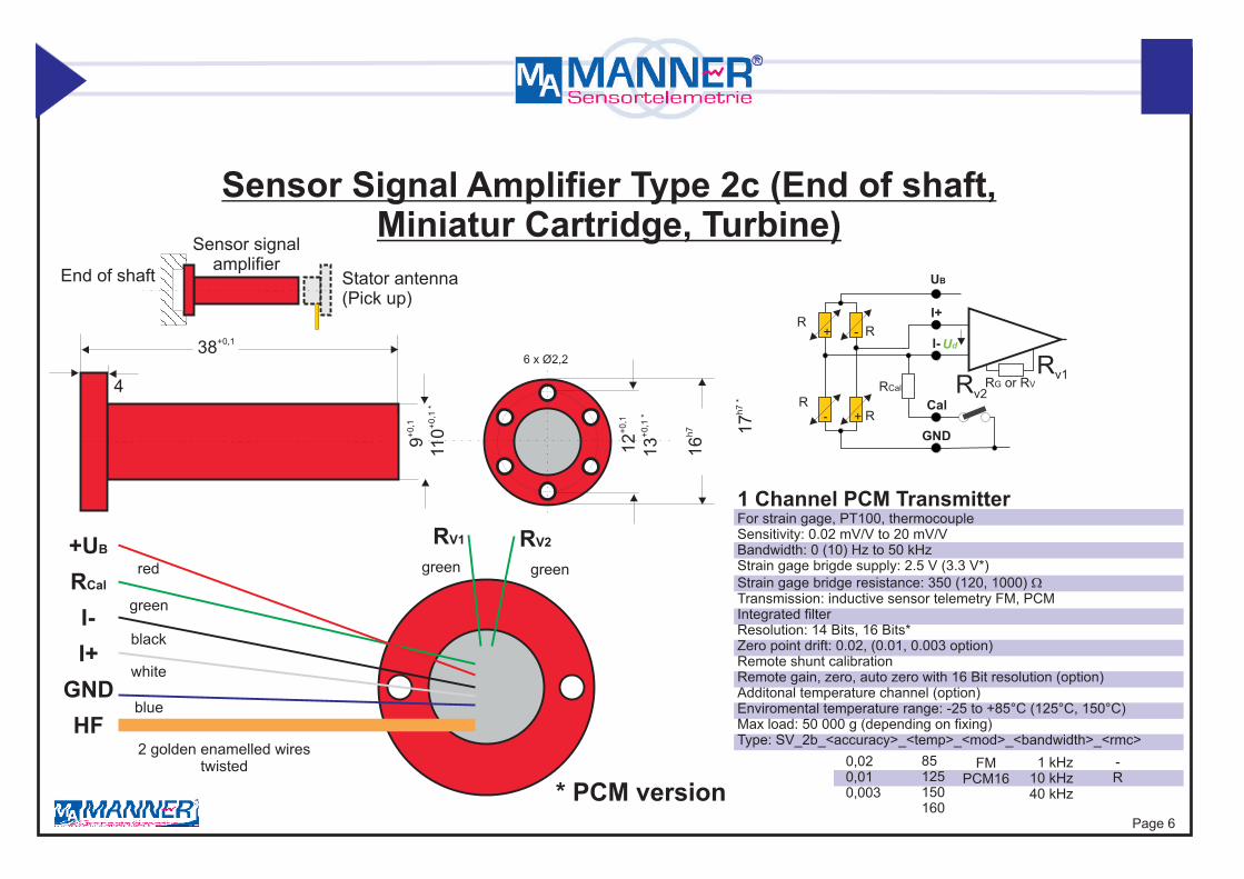
Sensor Signal Amplifier Type 2c (End of shaft, Miniatur Cartridge, Turbine)
+
+-
-R
R
RCal RG or RV
R
RUd
I+
Cal
GND
I-
UB
Rv1Rv2
6 x Ø2,2
HFGND
I+I-
RCal
+UB
2 golden enamelled wirestwisted
blue
white
black
greengreen
green
red
RV1 RV2
+0,1
9
+0,1
12
h716
+0,1
*11
0 +0,1
*13
h7 *
17
+0,138
4
* PCM version
Sensor signalamplifier
Stator antenna(Pick up)
End of shaft
Page 6
1 kHz10 kHz40 kHz
0,020,010,003
85125150160
FMPCM16
-R
1 Channel PCM TransmitterFor strain gage, PT100, thermocoupleSensitivity: 0.02 mV/V to 20 mV/VBandwidth: 0 (10) Hz to 50 kHzStrain gage brigde supply: 2.5 V (3.3 V*)Strain gage bridge resistance: 350 (120, 1000) WTransmission: inductive sensor telemetry FM, PCMIntegrated filterResolution: 14 Bits, 16 Bits*Zero point drift: 0.02, (0.01, 0.003 option)Remote shunt calibrationRemote gain, zero, auto zero with 16 Bit resolution (option)Additonal temperature channel (option)Enviromental temperature range: -25 to +85°C (125°C, 150°C)Max load: 50 000 g (depending on fixing)Type: SV_2b_<accuracy>_<temp>_<mod>_<bandwidth>_<rmc>

Sensor Signal Amplifier Type 2d ( Cartridge, Turbine)
Integrated Rotor Coil
End of shaft, Micro
+
+-
-R
R
RCal RG or RV
R
RUd
I+
Cal
GND
I-
UB
Rv1Rv2
*PCM version
2 x Ø1,7
HFGND
I+I-
RCal
+UB
2 golden enamelled wirestwisted
blue
white
black
green
red
+0,1
7
+0,1
10
+0,1
13
+0,1321
greengreen
RV1 RV2
Sensor signalamplifier
Stator antenna(Pick up)
End of shaft
1 kHz10 kHz40 kHz
0,020,010,003
85125150160
FMPCM16
-TC
1 Channel FM/PCM TransmitterFor strain gage, PT100, thermocoupleSensitivity: 0.02 mV/V to 20 mV/VBandwidth: 0 (10) Hz to 50 kHzStrain gage brigde supply: 2.5 V (3.3 V*)Strain gage bridge resistance: 350 (120, 1000) WTransmission: inductive sensortelemetry FM, PCMIntegrated filterResolution: 16 BitsZero point drift: 0.02, (0.01, 0.003 option)Remote shunt calibrationRemote gain, zero, auto zero with 16 Bit resolution (option)Additonal temperature channel (option)Enviromental temperature range: -25 to +85°C (125°C, 160°C)Max load: 50 000 g (depending on fixing)Type: SV_2d_<accuracy>_<temp>_<mod>_<bandwidth>_<rmc>_<TC>
Page 7

Sensor Signal Amplifier Type 2e (Disk, End of shaft, Small space)
+
+-
-R
R
RCal RG or RV
R
RUd
I+
Cal
GND
I-
UB
Rv1Rv2
* PCM version
10
Stator
6 x M3 Inbus(Radial coupling)
4558 644030
6 x Ø3,2
4 x Ø3,3
Ø4
Solder pins
Shaf
t
10
9
36
Page 8
1 kHz10 kHz40 kHz
0,020,010,003
85125150160
FMPCM16
-R
1 Channel FM/PCM TransmitterFor strain gage, PT100, thermocoupleSensitivity: 0.02 mV/V to 20 mV/VBandwidth: 0 (10) Hz to 50 kHzStrain gage brigde supply: 2.5 V (3.3 V*)Strain gage bridge resistance: 350 (120, 1000) WTransmission: inductive sensor telemetry FM, PCMIntegrated filterResolution: 14 Bits, 16 Bits*Zero point drift: 0.02, (0.01, 0.003 option)Remote shunt calibrationRemote gain, zero, auto zero with 16 Bit resolution (option)Additonal temperature channel (option)Enviromental temperature range: -25 to +85°C (125°C, 160°C)Max load: 50 000 g (max. speed: 30 0000 RPM)Type: SV_2e_<accuracy>_<temp>_<mod>_<bandwidth>_<rmc>

Wheel Transmitter with integrated Signal Amplifier Type 2f
Page 9
Stator
Rotor
Transducerconnection
Range conditioning
For more information see section: Universal shaft transmitter
+
+-
-R
R
RCal RG or RV
R
RUd
I+
Cal
GND
I-
UB
Rv1Rv2
Coupling
360 Pulses/turn.
Speed detection
1 kHz10 kHz40 kHz
0,020,010,003
85125160
90180360
FMPCM16
-R
-TC
1 Channel FM/PCM TransmitterBeared wheel transmitterFor strain gage, PT100, thermocoupleSensitivity: 0.02 mV/V to 20 mV/VBandwidth: 0 (10) Hz to 50 kHzStrain gage brigde supply: 6 V (3.3 V*)Strain gage bridge resistance: 120, 350, 1000 WTransmission: inductive sensor telemetry FM, PCMIntegrated filterResolution: 14 Bits, 16 Bits*Zero point drift: 0.02, (0.01, 0.003* option)Remote shunt calibrationSpeed detection: 360 pulses/turnEnviromental temperature range: -25 to +85°C (125°C, 160°C)Max load: 5 000 g (max. speed:10 000 RPM)Type: SV_2f_<accuracy>_<temp>_<mod>_<bandwidth>_<rmc>_<TC>_<RPM>

+
+-
-R
R
RCal RG or RV
R
RUd
I+
Cal
GND
I-
UB
Rv1Rv2
Coupling
48 Pulses/turn.
Speed detection
Option Speed
Page 10
1 Channel FM/PCM TransmitterFor strain gage, PT100, thermocoupleSensitivity: 0.02 mV/V to 20 mV/VBandwidth: 0 (10) Hz to 10 kHzStrain gage brigde supply: 6 V (3.3 V*)Strain gage bridge resistance: 120, 350, 1000 WTransmission: inductive sensor telemetry FM, PCMIntegrated filterResolution: 16 BitsZero point drift: 0.02, (0.01, 0.003* option)Remote shunt calibrationType: SV_2La_<Di>_<Da>_<temp>_<mod>_<bandwidth>_<rmc>_TC_<RPM>
Beared wheel transmitter
in mm 36 41 46 51
-10+85°C-25+125°C-45+85°C-45+125°C-25+160°C
PCM16in mm 59 65 69 75
Universal Shaft Transmitter with Sensor Signal Amplifier Type 2La(non divisible, 1 channel,with/without RMC, without rpm sensor)
For more information see section: Universal shaft transmitter
-R
-TC
1 kHz10 kHz40 kHz
DimensionsØ A [mm] Ø B [mm] C [mm] Ø D [mm] E [mm] F [mm]
36 45 37 59 70 1741 50 37 65 76 1746 55 37 69 83 1751 60 39 75 90 19
E
22,0 24,0
C
5,5
Ø B
2 x M3Through hole
F
Ø D
Ø A

+
+-
-R
R
RCal RG or RV
R
RUd
I+
Cal
GND
I-
UB
Rv1Rv2
Coupling
48 Pulses/turn.
Speed detection
Option Speed
1 Channel PCM TransmitterFor strain gage, PT100, ThermocoupleSensitivity: 0.02 mV/V to 20 mV/VBandwidth: 0 (10) Hz to 10 kHzStrain gage brigde supply: 6 V (3.3 V*)Strain gage bridge resistance: 120, 350, 1000 WTransmission: inductive sensor telemetry FM, PCMIntegrated filterResolution: 16 BitsZero point drift: 0.02, (0.01, 0.003* option)Remote shunt calibrationType: SV_2Lg_<Di>_<Da>_<temp>_<mod>_<bandwidth>_<rmc>_TC_<RPM>
Beared wheel transmitter
in mm 36 41 46 51
-10+85°C-25+125°C-45+85°C-45+125°C-25+160°C
PCM16in mm 59 65 69 75
Universal Shaft Transmitter with Sensor Signal Amplifier Type 2Lg(divisible, 1 channel,with/without RMC, without rpm sensor)
For more information see section: Universal shaft transmitter
-R
-TC
1 kHz10 kHz
2 x M3through hole
Ø D
E
25,0
24,0
C F
20,0
5,5
Ø A
Ø H
Ø B
Ø G
DimensionsØ A [mm] Ø B [mm] C [mm] Ø D [mm] E [mm]
36 50 70 66 8041 55 73 71 8546 60 75 76 90
-24
Page 11

Page 12
Sensor Signal Amplifier Type 3a
HFGND
9,1V5,8VTkI+I-
HF-GNDKal. Rv1
Rv2
UB
15 33
68 +0,2
+0,1
+0,2
+
+-
-R
R
RCal RG or RV
R
RUd
I+
Cal
GND
I-
UB
Rv1Rv2
Weight: about 10 g
* PCM version 1 kHz10 kHz40 kHz
0,020,010,003
85125150160
FMPCM16
-R
1 Channel FM/PCM TransmitterFor strain gage, PT100, thermocoupleSensitivity: 0.02 mV/V to 20 mV/VBandwidth: 0 (10) Hz to 50 kHzStrain gage brigde supply: 2.5 V (3.3 V*)Strain gage bridge resistance: 350 (120, 1000) WTransmission: inductive sensor telemetry FM, PCMIntegrated filterResolution: 14 Bits, 16 Bits*Zero point drift: 0.02, (0.01, 0.003 option)Remote shunt calibrationRemote gain, zero, auto zero with 16 Bit resolution (option)Additonal temperature channel (option)Enviromental temperature range: -25 to +85°C (125°C, 160°C)Max load: 50 000 g (depending on fixing)Type: SV_3a_<accuracy>_<temp>_<mod>_<bandwidth>_<rmc>_TC
TC

Page 13
38,0
24,0
17,0
Ø2,6
5,5 13,5 13,5
3,5
Sensor Signal Amplifier Type 3b
3,0
9,0
3,5
3,0
4,0 4,5 4,5
2.5V Cal GND
I- I+ 5,8V
HF1
HF2
TkRv1
HF-GNDRv2
* PCM version
+
+-
-R
R
RCal RG or RV
R
RUd
I+
Cal
GND
I-
UB
Rv1Rv2
1 kHz10 kHz40 kHz
0,020,010,003
85125150160
FMPCM16
-R
1 Channel FM/PCM TransmitterFor strain gage, PT100, thermocoupleSensitivity: 0.02 mV/V to 20 mV/VBandwidth: 0 (10) Hz to 50 kHzStrain gage brigde supply: 2.5 V (3.3 V*)Strain gage bridge resistance: 350 (120, 1000) WTransmission: inductive sensor telemetry FM, PCMIntegrated filterResolution: 14 Bits, 16 Bits*Zero point drift: 0.02, (0.,01, 0.003 option)Remote shunt calibrationRemote gain, zero, auto zero with 16 Bit resolution (option)Additonal temperature channel (option)Enviromental temperature range: -25 to +85°C (125°C, 160°C)Max load: 50 000 g (depending on fixing)Type: SV_3b_<accuracy>_<temp>_<mod>_<bandwidth>_<rmc>_TC
TC

Page 14
Sensor Signal Amplifier Type 3c
* PCM version
+
+-
-R
R
RCal RG or RV
R
RUd
I+
Cal
GND
I-
UB
Rv1Rv2
9,03,0
4,54,5 4,0
3,5
2.5V Cal GND HF1
HF2
TkRv1
HF-GNDRv2
Weight: about 12 g
I- I+ 5,8V
38,0
17,0
1 kHz10 kHz40 kHz
0,020,010,003
85125150160
FMPCM16
-R
1 Channel FM/PCM TransmitterFor strain gage, PT100, thermocoupleSensitivity: 0.02 mV/V to 20 mV/VBandwidth: 0 (10) Hz to 50 kHzStrain gage brigde supply: 2.5 V (3.3 V*)Strain gage bridge resistance: 350 (120, 1000) WTransmission: inductive sensor telemetry FM, PCMIntegrated filterResolution: 14 Bits, 16 Bits*Zero point drift: 0.02, (0.01, 0.003 option)Remote shunt calibrationRemote gain, zero, auto zero with 16 Bit resolution (option)Additonal temperature channel (option)Enviromental temperature range: -25 to +85°C (125°C, 160°C)Max load: 50 000 g (depending on fixing)Type: SV_3c_<accuracy>_<temp>_<mod>_<bandwidth>_<rmc>_TC
TC

+
+-
-R
R
RCal RG or RV
R
RUd
I+
Cal
GND
I-
UB
Rv1Rv2
dintegratedtemperature sensor
1 kHz2kHz
10 kHz
0,020,010,003
85125150160
FMPCM16
-R
-TC
1(2) Channel PCM TransmitterFor strain gage, PT100, thermocoupleSensitivity: 0.02 mV/V to 20 mV/VBandwidth: 0 (10) Hz to 50 kHzStrain gage brigde supply: 2.5 V (3.3 V*)Strain gage bridge resistance: 350 (120, 1000) WTransmission: inductive sensor telemetry PCMauto tuning circuit for rotor resonance (range 20..625pF) Resolution: 16 Bits (Integrated filters)Zero point drift: 0.02, (0.01, 0.003 option)Remote shunt calibrationRemote gain, zero, auto zero with 16 Bit resolution (option)Additonal temperature channel (option)Enviromental temperature range: -25 to +85°C (125°C, 150°C)Max load: 50 000 g (depending on fixing)Type: SV_3c_/#Ag625pF_<accuracy>_<temp>_<mod>_<bandwidth>_<rmc>_<TC>
auto
turn
ing
circ
uit
rotor antenna
self adapting to differentshaft diameters
(no extra capacity necessary)
Weight: about 12 g
Sensor Signal Amplifier Type 3c with auto turning _/#Agno manual resonant adjustment necessary
9,03,0
4,54,5 4,0
3,5
2.5V Cal GND HF1
HF2
Tk
HF-GND
I- I+38,0
17,0

Page 15
Sensor Signal Amplifier Type 4a
9,0
1,5
5,0
Weight: about 15 g
+
+-
-R
R
RCal RG or RV
R
RUd
I+
Cal
GND
I-
UB
Rv1Rv2
* PCM version
Ø3,1
Ø3,1
34,017,0
34,0
28,0
22,0
4,54,44,53,2 4,6 3,2
Rv1HF-GND HF2HF1Rv2 Tk
I+I- Cal. 5,8V2,5VGND 1 kHz10 kHz40 kHz
0,020,010,003
85125150160
FMPCM16
-R
1 Channel FM/PCM TransmitterFor strain gage, PT100, thermocoupleSensitivity: 0.02 mV/V to 20 mV/VBandwidth: 0 (10) Hz to 50 kHzStrain gage brigde supply: 2.5 V (3.3 V*)Strain gage bridge resistance: 350 (120, 1000) WTransmission: inductive sensor telemetry FM, PCMIntegrated filterResolution: 14 Bits, 16 Bits*Zero point drift: 0.02, (0.01, 0.003 option)Remote shunt calibrationRemote gain, zero, auto zero with 16 Bit resolution (option)Additonal temperature channel (option)Enviromental temperature range: -25 to +85°C (125°C, 160°C)Max load: 50 000 g (depending on fixing)Type: SV_4a_<accuracy>_<temp>_<mod>_<bandwidth>_<rmc>_TC
TC

Page 16
Sensor Signal Amplifier Type 4b Weight: about 12 g
+
+-
-R
R
RCal RG or RV
R
RUd
I+
Cal
GND
I-
UB
Rv1Rv2
* PCM version
9,0
1,5
Rv1HF-
GNDI+ I-Cal. 5,8V
HF2 HF1Rv2TkVcc GND
Ø2,7
Ø2,7
34,017,0
30,0
25,0
20,0
1 kHz10 kHz40 kHz
0,020,010,003
85125150160
FMPCM16
-R
1 Channel FM/PCM TransmitterFor strain gage, PT100, thermocoupleSensitivity: 0.02 mV/V to 20 mV/VBandwidth: 0 (10) Hz to 50 kHzStrain gage brigde supply: 2.5 V (3.3 V*)Strain gage bridge resistance: 350 (120, 1000) WTransmission: inductive sensor telemetry FM, PCMIntegrated filterResolution: 14 Bits, 16 Bits*Zero point drift: 0.02, (0.01, 0.003 option)Remote shunt calibrationRemote gain, zero, auto zero with 16 Bit resolution (option)Additonal temperature channel (option)Enviromental temperature range: -25 to +85°C (125°C, 160°C)Max load: 50 000 g (depending on fixing)Type: SV_4b_<accuracy>_<temp>_<mod>_<bandwidth>_<rmc>_TC
TC

Sensor Signal Amplifier Type 4c integrated Rotor Antenna (radial)
Weight: about 12 g+
+-
-R
R
RCal RG or RV
R
RUd
I+
Cal
GND
I-
UB
Rv1Rv2
* PCM version9,
0 13
1,5
Rv1HF-GNDI+ I-Cal. 5,8V
HF2 HF1Rv2TkVcc GND
Ø2,7
Ø2,7
34,017,0
30,0
25,0
20,0
Shaft
Page 17
1 kHz10 kHz40 kHz
0,020,010,003
85125150160
FMPCM16
-R
-TC
-spot
1 Channel FM/PCM TransmitterFor strain gage, PT100, thermocoupleintegrated rotor antennaSensitivity: 0.02 mV/V to 20 mV/VBandwidth: 0 (10) Hz to 50 kHzStrain gage brigde supply: 2.5 V (3.3 V*)Strain gage bridge resistance: 350 (120, 1000) WTransmission: inductive sensor telemetry FM, PCMIntegrated filterResolution: 14 Bits, 16 Bits*Zero point drift: 0.02, (0.01, 0.003 option)Remote shunt calibrationRemote gain, zero, auto zero with 16 Bit resolution (option)Additonal temperature channel (option)Enviromental temperature range: -25 to +85°C (125°C, 150°C)Max load: 50 000 g (depending on fixing)Type: SV_4c_<accuracy>_<temp>_<mod>_<bandwidth>_<rmc>_<TC>_<spot>

Sensor Signal Amplifier Type 4d integrated Rotor Antenna (axial)
Weight: about 12g
+
+-
-R
R
RCal RG or RV
R
RUd
I+
Cal
GND
I-
UB
Rv1Rv2
* PCM version12
Rv1HF-
GNDI+ I-Cal. 5,8V
HF2 HF1Rv2Tk
Vcc GND
Ø2,7
Ø2,7
34,017,0
30,0
25,0
20,0
Endof
shaft
Page 18
1 kHz10 kHz40 kHz
0,020,010,003
85125150160
FMPCM16
-R
-TC
1 Channel FM/PCM TransmitterFor strain gage, PT100, thermocoupleintegrated rotor antennaSensitivity: 0.02 mV/V to 20 mV/VBandwidth: 0 (10) Hz to 50 kHzStrain gage brigde supply: 2.5 V (3.3 V*)Strain gage bridge resistance: 350 (120, 1000) WTransmission: inductive sensor telemetry FM, PCMIntegrated filterResolution: 14 Bits, 16 Bits*Zero point drift: 0.02, (0.,01, 0.003 option)Remote shunt calibrationRemote gain, zero, auto zero with 16 Bit resolution (option)Additonal temperature channel (option)Enviromental temperature range: -25 to +85°C (125°C, 160°C)Max load: 50 000 g (depending on fixing)Type: SV_4d_<accuracy>_<temp>_<mod>_<bandwidth>_<rmc>_<TC>

Page 19
Sensor Signal Amplifier Type 5a (Standard)
Weight: about 8g
+
+-
-R
R
RCal RG or RV
R
RUd
I+
Cal
GND
I-
UB
Rv1Rv2
* PCM version
4 x Ø2,22,0
35,0
Ø15
,0
Ø 2
0,0
Ø 2
5,0
I+I- Rv2Tk
HF2HF1
1 kHz10 kHz40 kHz
0,020,010,003
85125150160
FMPCM16
-R
1 Channel FM/PCM TransmitterFor strain gage, PT100, thermocoupleSensitivity: 0.02 mV/V to 20 mV/VBandwidth: 0 (10) Hz to 50 kHzStrain gage brigde supply: 2.5 V (3.3 V*)Strain gage bridge resistance: 350 (120, 1000) WTransmission: inductive sensor telemetry FM, PCMIntegrated filterResolution: 14 Bits, 16 Bits*Zero point drift: 0.02, (0.01, 0.003 option)Remote shunt calibrationRemote gain, zero, auto zero with 16 Bit resolution (option)Additonal temperature channel (option)Enviromental temperature range: -25 to +85°C (125°C, 160°C)Max load: 50 000 g (depending on fixing)Type: SV_5a_<accuracy>_<temp>_<mod>_<bandwidth>_<rmc>_TC
TC

Sensor Signal Amplifier Type 5b (Standard)
Weight: about 8g+
+-
-R
R
RCal RG or RV
R
RUd
I+
Cal
GND
I-
UB
Rv1Rv2
* PCM version
4 x Ø2,22,0
35,0 Ø
15,0
Ø 2
0,0
Ø 2
5,0
I+ I-Rv2 Tk
HF2 HF1
Page 20
1 kHz10 kHz40 kHz
0,020,010,003
85125150160
FMPCM16
-R
1 Channel FM/PCM TransmitterFor strain gage, PT100, thermocoupleSensitivity: 0.02 mV/V to 20 mV/VBandwidth: 0 (10) Hz to 50 kHzStrain gage brigde supply: 2.5 V (3.3 V*)Strain gage bridge resistance: 350 (120, 1000) WTransmission: inductive sensor telemetry FM, PCMIntegrated filterResolution: 14 Bits, 16 Bits*Zero point drift: 0.02, (0.01, 0.003 option)Remote shunt calibrationRemote gain, zero, auto zero with 16 Bit resolution (option)Additonal temperature channel (option)Enviromental temperature range: -25 to +85°C (125°C, 160°C)Max load: 50 000 g (depending on fixing)Type: SV_5b_<accuracy>_<temp>_<mod>_<bandwidth>_<rmc>_TC
TC

Sensor Signal Amplifier Type 5c (Integrated Rotor Coil
Miniature Patrone)
+
+-
-R
R
RCal RG or RV
R
RUd
I+
Cal
GND
I-
UB
Rv1Rv2
* PCM version
2 x Ø1,7
HFGND
I+I-
RCal
+UB
2 golden enamelled wirestwisted
blue
white
black
green
red
+0,1
11 +0,1
13
+0,1
16
+0,1351
greengreen
RV1 RV2
Sensor signalamplifierEnd of shaft
Weight: 5 g2Torque of inertia: 1.5E-8 kgm
1 kHz10 kHz40 kHz
0,020,010,003
85125150160
FMPCM16
-RC
-TC
1 Channel FM/PCM TransmitterFor strain gage, PT100, thermocoupleSensitivity: 0.02 mV/V to 20 mV/VBandwidth: 0 (10) Hz to 50 kHzStrain gage brigde supply: 2.5 V (3.3 V*)Strain gage bridge resistance: 350 (120, 1000) WTransmission: inductive sensor telemetry FM, PCMIntegrated filterResolution: 14 Bits, 16 Bits*Zero point drift: 0.02, (0.01, 0.003 option)Remote shunt calibrationRemote gain, zero, auto zero with 16 Bit resolution (option)Additonal temperature channel (option)Enviromental temperature range: -25 to +85°C (125°C, 150°C)Max load: 50 000 g (depending on fixing)Type: SV_5c_<accuracy>_<temp>_<mod>_<bandwidth>_<rmc>_<TC>
Page 21

Sensor Signal Amplifier Type 5d (Super Integrated Rotor Coil
Miniature Patrone)
+
+-
-R
R
RCal RG or RV
R
RUd
I+
Cal
GND
I-
UB
Rv1Rv2
* PCM version
2 x Ø1,7
HFGND
I+I-
RCal
+UB
2 golden enamelled wirestwisted
blue
white
black
green
red
+0,1
7
+0,1
10
+0,1
*13
+0,1281
greengreen
RV1 RV2
Sensor signalamplifierEnd of shaft
Weight: 5 g2Torque of inertia: 1.5E-8 kgm
1 kHz0,020,01
85125150160
PCM16 -TCE
1 Channel FM/PCM TransmitterFor strain gage, PT100, thermocoupleSensitivity: 0.1 mV/V to 20 mV/VBandwidth: 0 (10) Hz to 1 kHzStrain gage brigde supply: 3.3 VStrain gage bridge resistance: 350 (120, 1000) WTransmission: inductive sensor telemetry PCMIntegrated filterResolution: 16 BitsZero point drift: 0.02, (0.01 option)Enviromental temperature range: -25 to +85°C (125°C, 150°C)Max load: 50 000 g (depending on fixing)Type: SV_5d_<accuracy>_<temp>_<mod>_<bandwidth>_<TC>
Page 22

Page 23
Miniatur Sensor Signal Amplifier Type 7a (Flatchip)
+
+-
-R
R
RCal RG or RV
R
RUd
I+
Cal
GND
I-
UB
Rv1Rv2
34
7 11
HFGND
I+I-
RCal
+UB
2 golden enamelled wirestwisted
blue
white
black
green
red
RV1
RV2
Weight:Epoxy: about 5g
1 kHz10 kHz40 (50) kHz
0,020,010,003
85125150160
FMPCM16
-R
-TC
1 Channel FM/PCM TransmitterFor strain gage, PT100, thermocoupleSensitivity: 0.02 mV/V to 20 mV/VBandwidth: 0 (10) Hz to 50 kHzStrain gage brigde supply: 2.5 V (3.3 V*)Strain gage bridge resistance: 350 (120, 1000) WTransmission: inductive sensor telemetry FM, PCMIntegrated filterResolution: 16 BitsZero point drift: 0.02, (0.01, 0.003 option)Remote shunt calibrationRemote gain, zero, auto zero with 16 Bit resolution (option)Additonal temperature channel (option)Enviromental temperature range: -25 to +85°C (125°C, 160°C)Max load: 50 000 g (depending on fixing)Type: SV_7a_<accuracy>_<temp>_<mod>_<bandwidth>_<rmc>_<TC>

Page 24
Super Miniatur Sensor Signal Amplifier Type 7b (Flatchip)Micro
+
+-
-R
R
RCal RG or RV
R
RUd
I+
Cal
GND
I-
UB
Rv1Rv2
34
4 7
HFGND
I+I-
RCal
+UB
2 golden enamelled wires twisted
blue
white
black
green
red
Weight:Epoxy: about 3g
1 kHz10 kHz
0,020,010,003
85125150160
FMPCM16
- -TC
1 Channel FM/PCM TransmitterFor strain gage, PT100, thermocoupleSensitivity: 0.02 mV/V to 20 mV/VBandwidth: 0 (10) Hz to 10 kHzStrain gage brigde supply: 2.5 V (3.3 V*)Strain gage bridge resistance: 350 (120, 1000) WTransmission: inductive sensor telemetry PCMIntegrated filterResolution: 16 BitsZero point drift: 0.02, (0.01, 0.003 option)Remote shunt calibrationfixed gain Enviromental temperature range: -25 to +85°C (125°C, 160°C)Max load: 50 000 g (depending on fixing)Type: SV_7b_<accuracy>_<temp>_<mod>_<bandwidth>_<rmc>_<TC>
100 mm
Urohyellow

Miniatur Sensor Signal Amplifier Type 7ke (Flatchip) with integrated Antenna (special for Chain Application)
+
+-
-R
R
RCal RG or RV
R
RUd
I+
Cal
GND
I-
UB
Rv1Rv2
30
8 11
HFGND
I+I-
RCal
+UB
2 golden enamelled wirestwisted
blue
white
black
green
red
RV1
RV2
Weight:Epoxy: about 8g
1 kHz10 kHz40 kHz
0,020,010,003
85125150160
FMPCM16
- -TC
1 Channel FM/PCM Transmitter with AntennaFor strain gage, PT100, thermocoupleSensitivity: 0.02 mV/V to 20 mV/VBandwidth: 0 (10) Hz to 50 kHzStrain gage brigde supply: 2.5 V (3.3 V*)Strain gage bridge resistance: 350 (120, 1000) WTransmission: inductive sensor telemetry FM, PCMIntegrated filterResolution: 16 BitsZero point drift: 0.02, (0.01, 0.003 option)Remote shunt calibrationRemote gain, zero, auto zero with 16 Bit resolution (option)Additonal temperature channel (option)Enviromental temperature range: -25 to +85°C (125°C, 160°C)Max load: 50 000 g (depending on fixing)Type: SV_Ke_<accuracy>_<temp>_<mod>_<bandwidth>_<rmc>_<TC>
Page 25

Page 26
+
+-
-R
R
RCal RG or RV
R
RUd
I+
Cal
GND
I-
UB
Rv1Rv2
Waterproof Sensor Signal Amplifier Type 8a
50,0
30,0
24,0
45,0
22,5
15,0
Housing BOPLA A10018,0
30,0
I+UB
HFGND
HF1 Rv2Rv1
Cal
HF2
5,8V
GNDI-
Tk
Thermocouple
* PCM-Version
1 kHz10 kHz40 kHz
0,020,010,003
85125150160
FMPCM16
-R
-TC
-Fu
1 Channel FM/PCM TransmitterFor strain gage, PT100, thermocoupleSensitivity: 0.02 mV/V to 20 mV/VBandwidth: 0 (10) Hz to 50 kHzStrain gage brigde supply: 2.5 V (3.3 V*)Strain gage bridge resistance: 350 (120, 1000) WTransmission: inductive sensor telemetry FM, PCMIntegrated filterResolution: 16 BitsZero point drift: 0.02, (0.01, 0.003 option)Remote shunt calibrationRemote gain, zero, auto zero with 16 Bit resolution (option)Additonal temperature channel (option)Enviromental temperature range: -25 to +85°C (125°C, 160°C)Max load: 50 000 g (depending on fixing)Type: SV_8a_<accuracy>_<temp>_<sys>_<mod>_<bandwidth>_<rmc>_<TC>_wa

Page 27
+
+-
-R
R
RCal RG or RV
R
RUd
I+
Cal
GND
I-
UB
Rv1Rv2
Waterproof Sensor Signal Amplifier Type 8b
50,0
30,0
24,0
45,0
22,5
15,0
Housing BOPLA A100
18,0
30,0
I+UB
HFGND
HF1 Rv2Rv1
Cal
HF2
5,8V
GNDI-
Tk
I I+Mess.GND
GND
HFGND
HF1
HF2
Rv1Rv2
Strain Gage Bridge/Thermo couple
Thermocouple
* PCM-Version
Pick Up/Receiver
Sen
sor S
igna
lver
stär
ker
transmitting 1 kHz10 kHz40 kHz
0,020,010,003
85125150160
FMPCM16
-R
-TC
-Fu
1 Channel FM/PCM Transmitterwith integrated radial antennaFor strain gage, PT100, thermocoupleSensitivity: 0.02 mV/V to 20 mV/VBandwidth: 0 (10) Hz to 50 kHzStrain gage brigde supply: 2.5 V (3.3 V*)Strain gage bridge resistance: 350 (120, 1000) WTransmission: inductive sensor telemetry FM, PCMIntegrated filterResolution: 16 BitsZero point drift: 0.02, (0.01, 0.003 option)Remote shunt calibrationRemote gain, zero, auto zero with 16 Bit resolution (option)Additonal temperature channel (option)Enviromental temperature range: -25 to +85°C (125°C, 160°C)Max load: 50 000 g (depending on fixing)Type: SV_8b_<accuracy>_<temp>_<sys>_<mod>_<bandwidth>_<rmc>_<TC>_wa

Page 28
+
+-
-R
R
RCal RG or RV
R
RUd
I+
Cal
GND
I-
UB
Rv1Rv2
Sensor Signal Amplifier Type 9especially for Driveshafts
* PCM version
Øinner
Øouter
Through holeØ = 7 mm for weight reduction
Inner diameter: 17 to 50 mmOuter diameter = Inner diameter + 20 mm
M3 Inbus
1 kHz10 kHz40 kHz
0,020,010,003
85125150160
FMPCM16
-R
-TC
1 Channel FM/PCM TransmitterFor strain gage, PT100, thermocoupleSensitivity: 0.02 mV/V to 20 mV/VBandwidth: 0 (10) Hz to 50 kHzStrain gage brigde supply: 2.5 V (3.3 V*)Strain gage bridge resistance: 350 (120, 1000) WTransmission: inductive sensor telemetry FM, PCMIntegrated filterResolution: 16 BitsZero point drift: 0.02, (0.01, 0.003 option)Remote shunt calibrationRemote gain, zero, auto zero with 16 Bit resolution (option)Additonal temperature channel (option)Enviromental temperature range: -25 to +85°C (125°C, 160°C)Max load: 50 000 g (depending on fixing)Type: SV_9_<accuracy>_<temp>_<mod>_<bandwidth>_<rmc>_<TC>
very low inertia

+
+-
-R
R
RCal RG or RV
R
RUd
I+
Cal
GND
I-
UB
Rv1Rv2
Sensor Signal Amplifier Type SV-Flex
Flexsubstrat
10
55
dintegrierteTemperatursensor
10
3
Sensor signal
amplifier
Very low inertia 1 kHz2kHz
10 kHz40 kHz
0,020,010,003
85125150160
FMPCM16
-R
-TC
1(2) Channel PCM TransmitterFor strain gage, PT100, ThermocoupleSensitivity: 0,02 mV/V to 20 mV/VBandwidth: 0 (10) Hz to 50 kHzStrain gage brigde supply: 2,5 V (3,3 V*)Strain gage bridge resistance: 350 (120, 1000) WTransmission: inductive sensortelemetry PCMIntegrated filterResolution: 16 BitsZero point drift: 0,02, (0,01, 0,003 option)Remote shunt calibrationRemote gain, zero, auto zero with 16 Bit resolution (option)Additonal temperature channel (option)Enviromental temperature range: -25 to +85°C (125°C, 160°C)Max load: 50 000 g (depending on fixing)Type: SV_Flex_<accuracy>_<temp>_<mod>_<bandwidth>_<rmc>_<TC>

Page 29
+
+-
-R
R
RCal RG or RV
R
RUd
I+
Cal
GND
I-
UB
Rv1Rv2
Sensor Signal Amplifier with auto turning Type SV-Flex_/#Agno manual resonant adjustment necessary
Flexsubstrat
10
73,3
dintegratedtemperature sensor
10
3
Sensor signal
amplifier
Very low inertia 1 kHz2kHz
10 kHz
0,020,010,003
85125150160
PCM16 -R
-TC
1(2) Channel PCM TransmitterFor strain gage, PT100, thermocoupleSensitivity: 0.02 mV/V to 20 mV/VBandwidth: 0 (10) Hz to 50 kHzStrain gage brigde supply: 2.5 V (3.3 V*)Strain gage bridge resistance: 350 (120, 1000) WTransmission: inductive sensor telemetry PCMauto tuning circuit for rotor resonance (range 20..625pF) Resolution: 16 Bits (Integrated filters)Zero point drift: 0.02, (0.01, 0.003 option)Remote shunt calibrationRemote gain, zero, auto zero with 16 Bit resolution (option)Additonal temperature channel (option)Enviromental temperature range: -25 to +85°C (125°C, 150°C)Max load: 50 000 g (depending on fixing)Type: SV_Flex_/#Ag625pF_<accuracy>_<temp>_<mod>_<bandwidth>_<rmc>_<TC>
auto turning circuit
auto
turn
ing
circ
uit
rotor antenna
self adapting to differentshaft diameters
(no extra capacity necessary)

Page 30
Evaluation Unit (84TE)
1 Channel FM/PCM ReceiverOutput: 0 to ±10 V, (0 (4) to 20 mA, frequency, binary, USB, CAN, TCP/IP)RF power: 1 W, 3 W, 5 WTransmission: inductive sensor telemetry FM, PCMIntegrated filterResolution: 12 Bits, 16 Bits*Remote shunt calibrationEnviromental temperature range: -25 to +70°CSupply: 9 to 36 V DC (board supply), 90 to 270 V AC 50/60 Hz
Bandwidth: 0 to 1 kHz (10 kHz,50 kHz)
Front side
G
O
Sensortelemetry
MA
132(3HE)
300
430(84 TE)
Multi ChannelReceiver
RemoteCalibration
Trace ATrace BTrace 0
Incremental/Absolutconverter(option)
Digital interface(option)
Ethernet(TCP/IP)CANUSB
Shaft encoder interface (option)
Antenna
SpeedPickup
90 to 270 volts
MAW_84TE_3_0.01_6,8MHz_PCM16_6700_1W_230VAC
1524
24B230
-UI
1W3W5W10W
70-45/85
FPCM12PCM16PCM24
-6
3,2
-InBaFu
InFu
-Dz
1 kHz 2 kHz 5 kHz10 kHz50 kHz
Type: AW_84TE_<Sys>_<Freq>_<mod>_<bandw>_<supply>_<RF-power>_<outA>_<Dint>_<temp>_<Dz>-FB
USBCAN
TCP/IPEtherCAT

Page 31
Evaluation Unit (42TE)Depth = 260 mm
Front side
G
O
Sensortelemetry
MA
132(3 HE)
225(42 TE)
300
Multi ChannelReceiver
RemoteCalibration
Trace ATrace BTrace 0
Incremental/Absolutconverter(option)
Digital interface(option)
Ethernet(TCP/IP)CANUSB
Shaft encoder interface (option)
Antenna
SpeedPickup
90 to 270 volts
1 Channel FM/PCM ReceiverOutput: 0 to ±10 V, (0 (4) to 20 mA, frequency, binary, USB, CAN, TCP/IP)RF power: 1 W, 3 W, 5 WTransmission: inductive sensor telemetry FM, PCMIntegrated filterResolution: 12 Bits, 16 Bits*Remote shunt calibrationEnviromental temperature range: -25 to +70°CSupply: 9 to 36 V DC (board supply), 90 to 270 V AC 50/60 Hz
Bandwidth: 0 to 1 kHz (10 kHz,40 kHz)
1524
24B230
-UI
1W3W5W10W
70-45/85
FPCM12PCM16PCM24
-6
3,2
-InBaFu
InFu
-Dz
1 kHz 2 kHz 5 kHz10 kHz
Type: AW_42TE_<Sys>_<Freq>_<mod>_<bandw>_<supply>_<RF-power>_<outA>_<Dint>_<temp>_<Dz>-FB
USBCAN
TCP/IPEtherCAT

Page 32
Evaluation Unit (22TE)
Front side
G
O
Sensortelemetry
MA
112(21TE)
132(3HE)
300
Multi ChannelReceiver
RemoteCalibration
Trace ATrace BTrace 0
Incremental/Absolutconverter(option)
Digital interface(option)
Ethernet(TCP/IP)CANUSB
Shaft encoder interface (option)
Antenna
SpeedPickup
90 to 270 volts
1 Channel FM/PCM ReceiverOutput: 0 to ±10 V, (0 (4) to 20 mA, frequency, binary, USB, CAN, TCP/IP)RF power: 1 W, 3 W, 5 WTransmission: inductive sensor telemetry FM, PCMIntegrated filterResolution: 12 Bits, 16 Bits, 24 BitsRemote shunt calibrationEnviromental temperature range: -25 to +70°CSupply: 9 to 36 V DC (board supply), 90 to 270 V AC 50/60 Hz
Bandwidth: 0 to 1 kHz (10 kHz,40 kHz)
1524
24B230
-UI
1W3W5W10W
70-45/85
FPCM12PCM16PCM24
-6
3,2
-InBaFu
InFu
-Dz
1 kHz 2 kHz 5 kHz10 kHz
Type: AW_22TE_<Sys>_<Freq>_<mod>_<bandw>_<supply>_<RF-power>_<outA>_<Dint>_<temp>_<Dz>-FB
USBCAN
TCP/IPEtherCAT

Evaluation Unit (AW_D)
MA MANNERSensortelemetrie
Sensorsignal-DrehübertragerPin 1: Output U: 0 to +/- 10 Volt Pin 8: Output I: 0 to + 20 mAPin 1: Output U: 0 to +/- 5 Volt Pin 8: Output I: 4 to + 20 mAPin 3: Input Mod.(Cal.)aktive low Pin 9: Output F:100kHz ±50kHzPin 3: Input Mod.(Cal.)aktive high Pin 9: Output F:25kHz ±12,5kHzPin 6: RPM PCMPin 7: Supply +15V +/-2%
Pin 2: GND OutputPin 7: Supply +24V +/-10% Pin 5: GND SupplyLED yellow: SupplyLED green: Signal
49,0
79,0
20,0
42
,0
72,0 M2,5
Page 33
Pin Assignmentof the D-Sub connectorPin 1 Output -10V to +10VPin 2 GND OutputPin 3 Remote Calibration SignalPin 4 do not connectPin 5 GND Power SupplyPin 6 do not connectPin 7 Power Supply 9 to 36 VDCPin 8 do not connectPin 9 do not connect
0 to ±10V
Single ChannelReceiver
RemoteCalibration
Antenna
SpeedPickup
Trace ATrace BTrace 0
Incremental/Absolutconverter(option)
Digital interface(option)
Shaft encoder interface (option)
1 Channel FM/PCM ReceiverOutput: 0 to ±10 V, (0 (4) to 20 mA, frequency, binaryRF power: 1 W, 3 W, 5 WTransmission: inductive sensor telemetry FM, PCMIntegrated filterResolution: 12 Bits, 16 Bits, 24 BitRemote shunt calibrationEnviromental temperature range: -25 to +70°CSupply: 24/15V
Bandwidth: 0 to 1 kHz (10 kHz,40 kHz)
1524
-UI
1W3W
70-45/85
FPCM12PCM16PCM24
-6,83,4
-InBaFu
InFu
-Hu
-Dz
1 kHz 2 kHz 5 kHz10 kHz
Type: AW_D_<Sys>_<Freq>_<mod>_<bandw>_<supply>_<RF-power>_<outA>_<Dint>_<temp>_<Dz>_<Mo>-FB
USB

Page 34
Evaluation Unit (AW_M)
Pin Assignmentof the D-Sub connectorPin 1 Output -10V to +10VPin 2 GND OutputPin 3 Remote Calibration SignalPin 4 do not connectPin 5 GND Power SupplyPin 6 do not connectPin 7 Power Supply 10 to 36 VDCPin 8 do not connectPin 9 do not connect
50,0
30,0
Ø3,3
60,0
130,0140,0
+ -
Eva
luat
ion
Uni
t
MA
MAN
NER
Sens
orte
lemet
rieR
G Z1 Channel FM/PCM ReceiverOutput: 0 to ±10 V, (0 (4) to 20 mA, frequency, binary)RF power: 1 W, 3 WTransmission: inductive sensor telemetry FM, PCM, RadioIntegrated filterResolution: 14 Bits, 16 BitsRemote shunt calibrationEnviromental temperature range: -10 to +70°C (-45 to +85°C)Supply: 24 (±5%) VDC (0,4 A/3W), 10 to 36 V DC (board supply)
Bandwidth: 0 to 1 kHz (10 kHz)
0 to ±10V
Single ChannelReceiver
RemoteCalibration
Antenna
SpeedPickup
Trace ATrace BTrace 0
Incremental/Absolutconverter(option)
Digital interface(option)
USB
Shaft encoder interface (option)
2424B
-UI
1W3W
70-45/85
FPCM12PCM16PCM24
-6,83,4
-InBaFu
InFu
-Dz
-Hu
1 kHz 2 kHz 5 kHz10 kHz
Type: AW_M_<Sys>_<Freq>_<mod>_<bandw>_<supply>_<RF-power>_<outA>_<Dint>_<temp>_<Dz>_<Mo>-FB

Evaluation Unit (AW_P)
1 Channel FM/PCM ReceiverOutput: 0 to ±10 V, (0 (4) to 20 mA, frequency, binary, USB, CAN)RF power: 1 W, 3 W, 5 WTransmission: inductive sensor telemetry FM, PCM, RadioIntegrated filterResolution: 14 Bits, 16 Bits, 24 BitsRemote shunt calibrationEnviromental temperature range: -10 to +70°C (-45 to +85°C)Supply: 24 (±5%) V DC, 10 to 36 V DC (board supply)
Bandwidth: 0 to 1 kHz (10 kHz)
Cover 'Zero' and 'Gain' screws after adjustment if necessary
With CAN-Bus Option available
Page 35
150
137
120
101 80
60
36
MA MANNERSensortelemetrie
TelemetryReceiver
+
Power
Signal rangeHF
Signal
-
Pin 1 :Pin 2 :Pin 3 :Pin 5 :Pin 7 :Pin 8 :
ZER
O
GA
IN
Ø5,2
Pin Assignmentof the D-Sub connector
Pin 1 Output -10V to +10VPin 2 GND OutputPin 3 Shunt Cal. (active low)Pin 4 do not connectPin 5 GND Power SupplyPin 6 do not connectPin 7 Power Supply 10 to 36 VDCPin 8 do not connectPin 9 do not connect
0 to ±10V
Single ChannelReceiver
RemoteCalibration
Antenna
SpeedPickup
Trace ATrace BTrace 0
Incremental/Absolutconverter(option)
Digital interface(option)
CANUSB
Shaft encoder interface (option)
2424B
-UI
1W3W5W
70-45/85
FPCM12PCM16PCM24
-6
3,2
-InBaFu
InFu
-Hu
-Dz
1 kHz 2 kHz 5 kHz10 kHz
Type: AW_P_<Sys>_<Freq>_<mod>_<bandw>_<supply>_<RF-power>_<outA>_<Dint>_<wa>_<temp>_<Dz>_<Mo>-FB
USBCAN
-IP65IP67

Evaluation Unit (AW_Ph)
Pin Assignmentof the D-Sub connector
Pin 1 Output -10V to +10VPin 2 GND OutputPin 3 Shunt Cal. (active low)Pin 4 do not connectPin 5 GND Power SupplyPin 6 do not connectPin 7 Power Supply 10 to 36 VDCPin 8 do not connectPin 9 do not connect
Cover 'Zero' and 'Gain' screws after adjustment if necessary Page 36
With CAN-Bus Option available
0 to ±10V
Single ChannelReceiver
RemoteCalibration
Antenna
SpeedPickup
Trace ATrace BTrace 0
Incremental/Absolutconverter(option)
9 to 36 V DC
Digital interface(option)
CANUSB
Shaft encoder interface (option)
1 Channel FM/PCM ReceiverOutput: 0 to ±10 V, (0 (4) to 20 mA, frequency, binary, USB, CAN)RF power: 1 W, 3 W, 5 WTransmission: inductive sensor telemetry FM, PCM, RadioIntegrated filterResolution: 14 Bits, 16 Bits, 24 BitsRemote shunt calibrationEnviromental temperature range: -10 to +70°C (-45 to +85°C)Supply: 24 (±5%) V DC, 10 to 36 V DC (board supply)
Bandwidth: 0 to 1 kHz (10 kHz)101 60
80
170
140
157
77
Ø5,2
MA MANNERSensortelemetrie
TelemetryReceiver
+
Power
Signal range
Signal
-
Pin 1 :Pin 2 :Pin 3 :Pin 5 :Pin 7 :Pin 8 :
HF
ZER
O
GA
IN
CA
N IN
CA
N O
UT
2424B
-UI
1W3W5W10W
70-45/85
FPCM12PCM16PCM24
-6
3,2
-InBaFu
InFu
-Dz
-Hu
1 kHz 2 kHz 5 kHz10 kHz
Type: AW_G_<Sys>_<Freq>_<mod>_<bandw>_<supply>_<RF-power>_<outA>_<Dint>_<wa>_<temp>_<Dz>_<Mo>-FB
USBCAN
-IP65IP67

Configuration(direct signal data acquisition,torque, no analog output)
Supply 9 to 36 V DC0 to ±10 V
Gain
Zero point
CAN-Bus TCP/IPUSB
Torque
Speed
TempNullpunkt
Meßbereich
-100
1
-80
2
-60
3
-40
4
-20
5
0
6
20
7
40
8
60
9
800
10 11 12
100
MV/V
% [-100..100]
MV/V [0...12,64]
Absolut[0.. 4095]-2,58 mV/V...+2,58 mV/V
Absolut[0.. 4095] Vmax...+Vmin
Übertragung Initialisieren
Exit
Transmit/Receive
Status
MA MANNERSensortelemetrie
R
Datei Info
Werte erneut senden
Zusatzfunktionen
Adjustment zero, gain, auto zero
Inductivesupply andtransmitting13.56 MHz
Coupling
Sensor signalamplifier
SpeedPickup
Speed channel
Torque Speed Power Temperature
t
Data stream
Page 40

Evaluation Unit (AW_F)
Pin Assignmentof the D-Sub connectorPin 1 Output -10V to +10VPin 2 GND OutputPin 3 Shunt Cal. (active low)Pin 4 do not connectPin 5 GND Power SupplyPin 6 do not connectPin 7 Power Supply 10 to 36 VDCPin 8 do not connectPin 9 do not connect
Cover 'Zero' and 'Gain' screws after adjustment if necessary Page 37
With CAN-Bus or TCP/IP or USB Option available
0 to ±10V
Single ChannelReceiver
RemoteCalibration
Antenna
SpeedPickup
Trace ATrace BTrace 0
Incremental/Absolutconverter(option)
Digital interface(option)
TCP/IPCANUSB
Shaft encoder interface (option)
1 Channel PCM ReceiverOutput: 0 to ±10 V, (0 (4) to 20 mA, frequency, binary, USB, CAN, TCP/IP, EtherCAT)RF power: 1 W, 3 W, 5 WTransmission: inductive sensor telemetry FM, PCM, RadioIntegrated filterResolution: 14 Bits, 16 Bits, 24 BitsRemote shunt calibrationEnviromental temperature range: -10 to +70°C (-45 to +85°C)Supply: 24 (±5%) V DC, 10 to 36 V DC (board supply)
Bandwidth: 0 to 1 kHz (10 kHz)
2424B
-UI
1W3W5W10W
70-45/85
FPCM12PCM16PCM24
-6
3,2
-InBaFu
InFu
-Dz
-HuLa
Traffic
Link
MAsignal range
110
22035(90)
1 kHz 2 kHz 5 kHz10 kHz
Type: AW_F_<Sys>_<Freq>_<mod>_<bandw>_<supply>_<RF-power>_<outA>_<Dint>_<temp>_<Dz>_<Mo>-FB
USBCAN
TCP/IPEtherCAT

Pin Assignmentof the D-Sub connectorPin 1 Output -10V to +10VPin 2 GND OutputPin 3 Shunt Cal. (active low)Pin 4 do not connectPin 5 GND Power SupplyPin 6 do not connectPin 7 Power Supply 9 to 36 VDCPin 8 do not connectPin 9 do not connect
Cover 'Zero' and 'Gain' screws after adjustment if necessary Page 38
With CAN-Bus or TCP/IP or USB Option available
0 to ±10V
Single ChannelReceiver
RemoteCalibration
Antenna
SpeedPickup
Trace ATrace BTrace 0
Incremental/Absolutconverter(option)
Digital interface(option)
TCP/IPCANUSB
Shaft encoder interface (option)
1 Channel PCM Receiver mit MiniDisplayOutput: 0 to ±10 V, (0 (4) to 20 mA, frequency, binary, USB, CAN, TCP/IP)RF power: 1 W, 3 W, 5 WTransmission: inductive sensor telemetry FM, PCM, RadioIntegrated filterResolution: 14 Bits, 16 Bits, 24 BitsRemote shunt calibrationEnviromental temperature range: -10 to +70°C (-45 to +85°C)Supply: 24 (±5%) V DC, 15 (±2%) V DC, 9 to 36 V DC (board supply)
Bandwidth: 0 to 1 kHz (10 kHz)
1524
24B
-UI
1W3W5W10W
70-45/85
FPCM12PCM16PCM24
-6
3,2
-InBaFu
InFu
-Dz
-HuLa
Traffic
Link
MAsignal range
110
22035(90)
1 kHz 2 kHz 5 kHz10 kHz
Type: AW_F_<Sys>_<Freq>_<mod>_<bandw>_<supply>_<RF-power>_<outA>_<Dint>_<temp>_<Dz>_<Mo>-FB
USBCAN
TCP/IPEtherCAT
3.745

Thermoelement Typ K
Topologiedigital
ReceiverTyp MAW_F...
digital Receiver
Typ MAW_F...
digital Receiver
Typ MAW_F...
digital Receiver
Typ MAW_F...
4 m
4 m
4 m
4 m
Speed
Speed
Speed
Speed
Torque
Speed
TempNullpunkt
Meßbereich
-100
1
-80
2
-60
3
-40
4
-20
5
0
6
20
7
40
8
60
9
800
10 11 12
100
MV/V
% [-100..100]
MV/V [0...12,64]
Absolut[0.. 4095]-2,58 mV/V...+2,58 mV/V
Absolut[0.. 4095] Vmax...+Vmin
Übertragung Initialisieren
Exit
Transmit/Receive
Status
MA MANNERSensortelemetrie
R
Datei Info
Werte erneut senden
Zusatzfunktionen
Adjustment zero, gain, auto zero
Ether-CAT
Ether-CAT
Ether-CATController
Ether-CAT
Ether-CAT
Ether-CAT
TCP/IP
4/8 Channel Temperaturtelemetry
Torque
Multi Channel SG Telemetry
Single Channel Telemetry
ControllTest rigg
Sensortelemetry
Visualisation

Page 39
1 Channel MGC-Plugin Unit FM/PCM ReceiverOutput: 5 to 15 kHzRF power: 3 WTransmission: inductive sensor telemetry FM, PCM, RadioIntegrated filterResolution: 16 BitsRemote shunt calibrationEnviromental temperature range: -10 to +70°CSupply: 17 (±5%) V DC, 15 (±2%) V
Bandwidth: 0 to 1 kHz
1 kHz 17VF 2W FuPCM16
-6,83,4
0 to ±10V
Single channelreceiver
RemoteCalibration
AntennaMGC interface MGC
Plug in cardType: AW_ES_MGC
MA
Evaluation MGC Plugin Unit (AW_ES_MGC)
Freq.
HF
Type: AW_EG_<Sys>_<Freq>_<mod>_<bandw>_<supply>_<RF-power>_<outA>-
InBaFu
InFu

Multi channelsensor signal
amplifier Inductivesupply andtransmitting13,56 MHz
90 to 270V AC(9 to 36 V DC)
PT100 RTD
Remotecalibration
Remote control(option)
voltage0..+/-10 V
Strain gagefull brigde
Thermocouple
PT100
Coupling
Configuration
Strain gagefull brigde
stat
ionä
res
Sen
sorin
terfa
ce(m
ax. 8
cha
nnel
sS
enso
rtele
met
rie-
inte
rface
Digital combi Data acquisition (Sensortelemetry + stationary Channels)(direct signal data acquisition)
Dat
a ac
qusi
tion
unit
USB,TCP-IP
configureableanalogic inputs
Speed
Page 41

1 Channel PCM Receiver with additional stationary ChannelsOutput: 0 to ±10 V, (0 (4) to 20 mA, frequency, binary, USB, CAN, TCP/IP)RF power: 1 W, 3 W, 5 WTransmission: inductive sensor telemetry FM, PCM, RadioIntegrated filterResolution: 14 Bits, 16 Bits*Remote shunt calibrationAdditional 4/8 static configurable signal inputs (strain gauge, voltage,etc.) with remote conditioningDigital Interface USB oder EthernetEnviromental temperature range: -10 to +70°C (-45 to +85°C)Supply: 90 to 270 volts AC, 24 (±5%) V DC, 15 (±2%) V DC, 9 to 36 V DC (board supply)
Bandwidth: 0 to 1 kHz (10 kHz)
1 kHz 2 kHz 5 kHz10 kHz
2301524
24B
BUSBCAN
TCP/IPEtherCAT
1W3W5W10W
70-45/85
FPCM16PCM24
-6,83,4
-48
-Sta
-HuBa
-Dz
Digital combi Data Acquisition (Sensor telemetry + stationary Channels)(direct signal data acquisition)
Page 42
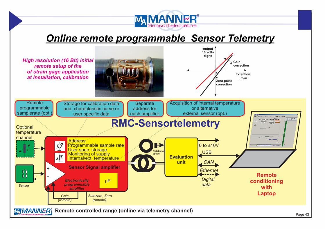
Advantages:* data acquisition system for rotor and stator signal in 1 unit* very compact and light weight data acquisition system* Isochronious sampling of rotor and stator signals* digital interface direct to PC with software* additional speed acquistion channel (option)* easy handling - ideal for mobil application
Type: AW_F_<Sys>_<Freq>_<mod>_<bandw>_<supply>_<RF-power>_<Dint>_<temp>_<Dz>_<Mo>_<sta><x>-
InBaFu
InFu
Sensor
Evaluationunit CAN
Ethernet+-
Electronicallyprogrammable
amplifier
Gain (remote)
Autozero, Zero (remote)
Digitaldata
Online remote programmable Sensor Telemetry
RMC-Sensortelemetry
Remote controlled range (online via telemetry channel)
Storage for calibration dataand characteristic curve or
user specific data
Separateaddress for
each amplifier
Acquisition of internal temperatureor alternative
external sensor (opt.)
Remote programmable
samplerate (opt.)
Optionaltemperaturechannel
d
d
µP
USB0 to ±10V
Rotationalspeed
Remote conditioning
withLaptop
output10 voltsdigits
Extentionmm/m
Zero pointcorrection
Gaincorrection
High resolution (16 Bit) initial remote setup of the
of strain gage applicationat installation, calibration
Programmable sample rateAddress
Monitoring of supply Internal/ext. temperature
User spec. storage
Sensor Signal amplifier
Page 43

Display Software and special Configurations(Software Package Remote Control)
When using the software for the first time the hardware must be configuredselect menue -> Setup -> Hardware configuration' to configure
Not all functions are available in every hardware configuration
User programmable d ield(saved in the rotor-memory)
esciption f
Desciption field 1
Read the temperature of therotor electronic via RMC
Desciption field 2
Start display dataStop display data
Selection of the available USB devices,appears if more than one devices are connected
Display of the measvalue channel 1
Bar diagram of the analogoutput value
Display settings:Unit, Scale, Offset
Average: Number of valuesused for averaging of thedisplayed analog value
Communication display: Receive / Transmit / Acknowledgeadditionally Low-Power (in radio applications)
Save: Saves the display settings
Display of the selected hardware configuration
Start / Stop of the Test-RMCtransmission
Uses predefined settings for the display configuration
Page 44

Remote Control forrotor electronic (range/autozero/shunt calibration)
(Software Package Remote Control)
Remote calibration on/off
Automatic zero point Calculates the offset on the basis of the actual measured valueand the actual gain to correct the output voltage to Zero.If necessary do this function repetitive.To save this offset permanently store it with'Send and store'.
Read actual active values This function allows the readbackof the saved (EEPROM on rotor)settings of the rotor measuring amplifier.It is useful to read back these valuesat start paramerters before startingthe adjustment.
Transmission of the settings- temporary storage:The settings keep actual as long as themeasuring amplifier is powered. If thepower supply breaks the previousstored settings will get active.This function is useful for testsor alternative settings because it allowsa quick update of the measuredvalue. After a successful adjustmentthe settings can be stored permanentlyinto the EEPROM of the rotor with'Send and store'.
Transmission of the settings- permanent storage:Zero point and gain are sent to themeasuring amplifier and storedpermanently in the EEPROM of the rotor.
Input field for the sensitivity
Input for the zero point
Automatic range set Allows to automatic range set during applied load
Selection of the used temperaturesensor:internal sensor (standard) or external temperature-diode (2nd channel)
Page 45

Page 46
Data Recording Software(Software Package data acquisition - optional)
Start recording into a file
Stop recording into a file
Show data with additional external viewer PVIEW - if installed
Display file operationactivity
No other program must be active at the PC while recording data into a file.This can effect a loss of data.
Number of saved samples
Input field for path and file name
Additional information,which is saved in the description files
Option for RPM-systemssave calculated rpm or saverpm-pulses to datafileOn menue setup, there is the possibility to activate an averaging for the calculated rpm.For option 'Calculated RPM' take care of the correct setting at configuration(Samplerate).
time
time
rpm
rpmpulses
or
Shunt calibration on/off
Recording sample rate reductionfactor
Temperature channel recording(option)
Speed channel recording(option)
Readed value channel 1
Readed value channel 2 (temperature)

Power [KW]
-100.00
Data Display Software Pview(Software Package data acquisition - optional)
Torque [Nm]
Visualisation of recorded datas
Page 47

Page 48
Format of the binary file (.DAT) orASCII file (.CSV)
Definition: LB = low byte, HB =high byteFirst the low byte and then the high byte of a channel is recordedThe range of a 12 and 16 bit system is from 0 to 65535For 12 bit-systems, the lowest 4 bits are set to 0
Realtime recorded Data File
User specificanalysis program
Pviewvisualisation
program(part of software package
data acquisition)
Excel or other
analysisprogramms
Data Interface

Data FormatThe data are recorded in a binary format. The file has the ending ‘.DAT’. The data can be imported in every analysing software, which can handle with binary data.
Additionally there are generated two description files:
- MDF-description-file: This file is used to descript the structure of the binary file. . The description file is necessary for the data viewing software PVIEW from Stiegele Datensysteme GmbH.
- Text-description-file: Description information in plane text
Format of the Binary File (.DAT)Definition: LB= Low Byte, HB=High-ByteFirst the Low-Byte and then the High-Byte of a channel is recorded.The range of a 12 and 16 bit system is from 0 to 65535For 12 bit-systems, the lowest 4 bits are set to 0
Assignment to the analog values: Excitation 100% (correspond to analog output +10V) digital value 62259 for 16 Bit-Systems Excitation 0% (correspond to analog output 0V) digital value 32768 for 16 Bit-Systems Excitation -100% (correspond to analog output - 10V) digital value 3277 for 16 Bit-Systems
Exciation [%] = (Digital-Value - 32768) / 294.91 for 16 Bit-Systems
Values, which exceed this range are not within the measuring range.The time between two measvalues in the .DAT-file corresponds to the reciprocal value of the sample rate of the system (see page technical data)
A optional calculated power-value is saved as 4-Byte float.
Data file format(Software package Data acquisition modul - optional)
Page 49

[Data-Description file]Version: 1.0Binary-Filename: dataset1.datTime of Record: 24.01.2008 17:15:39Samples per Frame: 2Bytes per Sample 4Samplerate [1/s] 6511,48
[Channeldescription]Channelnumber: 1Name: Ch1Label: Channel 1Unit: VFactor: 0,000339086500966397Constant: -11,1111864636669
Channelnumber: 2Name: Ch2-RPMLabel: RPMUnit: 1/sFactor: 1Constant: 0
Data File-Structure(Software package Data acquisition modul - optional)
Structure of the Binary File with extension .DAT: Sample file shown with a Hex Viewer
Second measvalue
First measvalueFF=Low Byte 7F=High Byte
Structure of the Text Descitiption File with extension .txt (structe shown for a system with two channels)
Factor and offsetconstant to calculate the physical value from the binary valueExample: Binary Value 62259 * (0,00033908..)+ (-11,1111..) = 10 V [Unit]
Dataformat: 4 for 2-Byte Integer, 9 for 4-Byte Floatingpoint
Page 50

Signal test function via Scope function(Software package Data acquisition modul - optional)
Setting time base
Setting gain
Setting offset actual power
actual speed
Nm
actual torque
actual readings
Page 51

Automatic zero drift correction function(Software package RMC modul - optional)
temperature
temperature
deviationof outputsignal
deviationof outputsignal
0°C
0°C
-25°C
-25°C
25°C
25°C
50°C
50°C
75°C
75°C
100°C
100°C
125°C
125°C
150°C
150°C
Torque shaft
Torque shaft
acquistion of zero drift
check of oneline correction
result
final result - no zero drift
calculation correctionparameters
programming of online correctionparameters inside sensor signal amplfier
Δy150°CΔy125°C
Δy100°CΔy50°C
Δy-25°C
Δy-25°C
deviations
Sensor
+-
RMC-Sensortelemetry
d
d
µP
Sensor Signal amplifier
correctionparameters
Evaluationunit
special drift correction softwar
result: fully compensation
of the zeropoint drift
high precisiontorque measurement
Page 52

Software für Zero Drift Adjustment

Torque/Power acquisition on shaft
shaft
Drehmoment-aufnehmer
Integratedsensor signal
amplifier
Pickup
Welle
divisible rotor antenna
Receiver
Antenna cableType RG316
Bahrgraph
9 pol D-Sub (supply and signal)
Sensor signalamplifier
torquetransducer
ReceiverTorque
Drehzahl
output (U,I, USB, CAN, Ethernet)
Speed acquisition
* high precise torque acquisition based on strain gauge* integrated power supply (no batteries)* no maintainance, easy mounting* special for longterm use* digital interface* environment temperature range -45..160°C
Page 53

Ø3,1
Ø3,1
34,017,0
36,0
13,0
1,0
30,0
24,0
++ +
-
- -
RV
Rg
L
L L
LL L
Ud
I+
I-
Rv1
Rg1Rv2
Rg2
LVDTConverter
.
.
.
.
.
.~
~
Vs-
Vs+
Gndalternativefull brigde
M M
I+
I-
Vout+/1,25volts
s
LVDT - Interface ModulFor displacement sensor, position sensors differential, inductive full brigdesNumber of channels: 1Transducer types: displacement sensor, differential transformers, fullbridgeSensitivity: 80 mV/V (1 mV/V to 200 mV/V)Bandwidth: 0 to 1 kHz Transducer Supplydifferential (Vs+~- Vs-~) = 3.5 volts ppFrequency of supply transducer: 10 kHzmin. Transducer resistor at f = 10 kHz: 350 Woutput signal differential to M 0 to +±1.25 voltsSupply Vss > 5.3 voltscurrent consumption 40 mAZero point drift: 0,02 %/°CentigradeEnviromental temperature range: -25 to +85°C (125°C, 150°C)Max load: 20 000 g (depending on fixing)Housing (external Modul): 36 x 34 x 13 mm, or integration in SVExternal Interface Modul Type displacement external: Type displacement internal:
KondLV#xxxmm# #extKondLV#xxxmm# #F
Vs+~
Vs-~
I+
I- Gnd
Vc
Rv
Rg
Vss
Gndss
Vout
M
Gndss Gnd
Vss Vss> 5,3 volts
Modul
Smax.-Smin.
Vout+1.25 volts
-1.25 volts
Sensor-signalamplifier
external LVDT - Interface Modul
Transfer Characteristic
Page 54

Ø3,1
Ø3,1
34,017,0
36,0
13,0
1,0
30,0
24,0
-Rg
L
UdI
Rg1Rg2
u-EpsS05Converter
.
.
.
.
.
.
~ ~~~
Gnd
M M
I+
I-
Vout+/1,25volts
s
U-Eps - Interface ModulFor displacement sensors Ueps S05 and U05Number of channels: 1Sensitivity: adapted to total range: 0 to 0.4 mmBandwidth: 0 to 1 kHz Frequency of supply transducer: 2 Mhz +/- shift
Supply Vss > 5.3 voltscurrent consumption 40 mATemperature shift compensated by measuring transducer temperatureZero point drift: 0.1 %/°centigrade (-0 to +85°C)Enviromental temperature range: -25 to +85°C (125°C, 150°C)Max load: 20 000 g (depending on fixing)Housing (external Modul): 36 x 34 x 13 mm, or integration in SVExternal Interface Modul Type displacement external: Type displacement internal:
output signal differential to M 0 to ±1.25 volts
KondEp#xxxmm# #extKondEp#xxxmm# #F
I
Gnd
Rv
Vss
Gndss
Vout
M
Gndss Gnd
Vss Vss> 5,3 volts
Modul
Smax.
0
Vout+1.25 volts
Transfer Characteristic
Sensor-signalamplifier
external uEps Sensor- Interface Modul
2 Mhz
displacement sensor
non linear
typical0, 4 mm
Page 55

+
+-
-R
R
RCal RG or RV
R
RUd
I+
Cal
GND
I-
UB
Rv1Rv2
Sensor Signal Amplifier Type SV-Flex with integrated torque strain gauge sensor
Flexsubstrat62
dintegrierteTemperatursensor
10
3
Sensor signal
amplifier
Very low inertia 1 kHz2kHz
10 kHz40 kHz
0,020,010,003
85125150160
FMPCM16
-RC
-TC
1(2) Channel FM/PCM Torque TransmitterFor strain gage, PT100, thermocoupleSensitivity: 0.02 mV/V to 20 mV/VBandwidth: 0 to 1 Hz to 2 kHzStrain gage brigde supply: 3,3 VSensor SG Foil Full brigd (resistance 1000 W)range: 0,050 um/m to 8000 um/mTransmission: inductive sensor telemetry PCMIntegrated filterResolution: 16 BitsZero point drift: 0.01, 0.003 option)Remote shunt calibrationRemote gain, zero, auto zero with 16 Bit resolution (option)Additonal temperature channel (option)Enviromental temperature range: -25 to +85°C (125°C, 160°C)Type: SV_Flex_<accuracy>_<temp>_<mod>_<bandwidth>_<rmc>_<TC>
10
integrierter Torquesensor
Page 56

Evaluation Unit (AW_DAnt)
MA MANNERSensortelemetrie
Sensorsignal-DrehübertragerPin 1: Output U: 0 to +/- 10 Volt Pin 8: Output I: 0 to + 20 mAPin 1: Output U: 0 to +/- 5 Volt Pin 8: Output I: 4 to + 20 mAPin 3: Input Mod.(Cal.)aktive low Pin 9: Output F:100kHz ±50kHzPin 3: Input Mod.(Cal.)aktive high Pin 9: Output F:25kHz ±12,5kHzPin 6: RPM PCMPin 7: Supply +15V +/-2%
Pin 2: GND OutputPin 7: Supply +24V +/-10% Pin 5: GND SupplyLED yellow: SupplyLED green: Signal
49,0
21,0
42,0
72,0 M2,5
Page 57
Pin Assignmentof the D-Sub connectorPin 1 Output -10V to +10VPin 2 GND OutputPin 3 Remote Calibration SignalPin 4 do not connectPin 5 GND Power SupplyPin 6 do not connectPin 7 Power Supply 24 VDCPin 8 do not connectPin 9 do not connect
0 to ±10V
Single ChannelReceiver
RemoteCalibration
Antenna
SpeedPickup
Trace ATrace BTrace 0
Incremental/Absolutconverter(option)
Digital interface(option)
Shaft encoder interface (option)
1 Channel FM/PCM Receiver with integrated Pick UPOutput: 0 to ±10 V, (0 (4) to 20 mA, binaryRF power: 1 W, 3 W, Transmission: inductive sensor telemetry PCM, integrated Pick UPIntegrated filterResolution: 12 Bits, 16 BitsRemote shunt calibrationEnviromental temperature range: -25 to +70°CSupply: 24V
Bandwidth: 0 to 1 kHz (10 kHz)
24 -UI
1W3W
70PCM12PCM16
--
IndInBa
-Hu
-Dz
1 kHz 10 kHz
Type: AW_D_<Sys>_<Freq>_<mod>_<bandw>_<supply>_<RF-power>_<outA>_<Dint>_<temp>_<Dz>_<Mo>
78,4 89

Trum
Pick UP
rotatingmeasurement amplifierwith integrated antenna
rotatingmeasurement amplifierwith integrated antenna
Monitoring Temperature/Pressure on rotating Shaftwith operating mode Spot ( 1 sample/turn)
1(4) Channel- PCM TransmitterFor strain gage, PT100, thermocouple Typ KMode: 1 sample/turnInput Sensitivity: 0,2 mV/V to 20 mV/Vmin. signal contact time: 1.3 msStrain gage brigde supply: 3.3 VPressure sensor SG Foil full bridgd (resistance 1000 W)Transmission: inductive sensor telemetry PCMIntegrated filterResolution: 16 BitsZero point drift: 0.01, 0.003 option)Enviromental temperature range: -25 to +85°C (125°C, 160°C)
Page 58
TC
Trum
Pick Up
radial or axial

1 kHz0,02 85125150160
FMPCM
1 Channel FM/PCM TransmitterFor strain gage, PT100, thermocoupleSensitivity: 0.02 mV/V to 20 mV/VBandwidth: 0 to 1kHzStrain gage brigde supply: 2.5 V (3.3 V*)Strain gage bridge resistance: 350 (120, 1000) WTransmission: inductive sensor telemetry FM, PCMIntegrated filterResolution: 16 Bits*Zero point drift: 0.02Remote shunt calibrationRemote gain, zero, auto zero with 16 Bit resolution (option)Additonal temperature channel (option)Enviromental temperature range: -25 to +85°C (125°C, 160°C)Max load: 50 000 g (depending on fixing)Type: SV_Sc_<accuracy>_<temp>_<mod>_<bandwidth>_TC
TC
Ud
I+
I- 1 Channel 1......
Cold junction compensation
.
.
.
.
.
~~~+
-
1 Channel Temperature Sensor Signal Amplifier Type Sc(Screw Terminal Block)
Ø2,7
Ø2,734,0
17,0
30,0
25,0
20,0
9,0
Rv1HF-
GND5,8V
HF2 HF1Rv2
19,4
Page 59
+
+-
-R
R
RCal RG or RV
R
RUd
I+
Cal
GND
I-
UB
Rv1Rv2
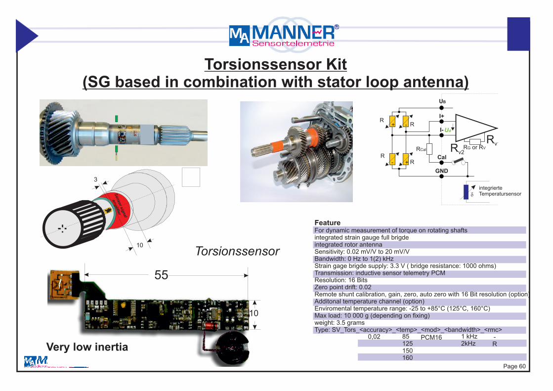
Torsionssensor Kit (SG based in combination with stator loop antenna)
Torsionssensor
10
55
dintegrierteTemperatursensor
10
3
Sensor signal
amplifier
Very low inertia 1 kHz2kHz
0,02 85125150160
PCM16 -R
FeatureFor dynamic measurement of torque on rotating shaftsintegrated strain gauge full brigdeintegrated rotor antennaSensitivity: 0.02 mV/V to 20 mV/VBandwidth: 0 Hz to 1(2) kHzStrain gage brigde supply: 3.3 V ( bridge resistance: 1000 ohms)Transmission: inductive sensor telemetry PCMResolution: 16 BitsZero point drift: 0.02 Remote shunt calibration, gain, zero, auto zero with 16 Bit resolution (option)Additonal temperature channel (option)Enviromental temperature range: -25 to +85°C (125°C, 160°C)Max load: 10 000 g (depending on fixing)weight: 3.5 gramsType: SV_Tors_<accuracy>_<temp>_<mod>_<bandwidth>_<rmc>
Page 60

+
+-
-R
R
RCal RG or RV
R
RUd
I+
Cal
GND
I-
UB
Rv1Rv2
Torsionssensor
75
leng
th d
epen
dson
sha
ft di
amet
er
80
dintegrierteTemperatursensor
Torsionssensor Kit (simple/rapid mounting without soldering, SG based)
Very low inertiaStrain gauge
Flex- Rotorantenna
Flex- Sensor signal amplifier
10,5
1 kHz2kHz
0,02 85125150160
PCM16 -R
FeatureFor dynamic measurement of torque on rotating shafts (power train)integrated strain gauge full brigdeintegrated loop rotor antenna (variable shaft diameter)Kit solution simple/rapide mounting (with instructions, clue kit)direkt mounting on shaft without soldering Sensitivity: 0.02 mV/V to 20 mV/VBandwidth: 0 Hz to 1(2) kHzStrain gage brigde supply: 3.3 V ( bridge resistance: 1000 ohms)Transmission: inductive sensor telemetry PCMResolution: 16 BitsZero point drift: 0.02 Remote shunt calibration, gain, zero, auto zero with 16 Bit resolution (option)Additonal temperature channel (option)Enviromental temperature range: -25 to +85°C (125°C, 160°C)Max load: 10 000 g (depending on fixing)weight: 5 grams (depends on shaft diameter)Type: SV_Tors_x/y_<accuracy>_<temp>_<mod>_<bandwidth>_<rmc>
30/4060/8080/120
halve shaft
probe shaft
Page 61

Type: SV_Rad_<size>_<speed>_ <accuracy>_<temp>_<VFreq>_<sys>_<mod>_<sample>_<bandwidth>_<rmc>_<wa>_<TC>_<range>
Type: AW_84H6_<VFreq>_<sys>_<mod>_<bandwith>_<power>_<supply>_<outpA>_DInt>_<Temp>_<RPM>_<wa>_<sta>
rangesensor type (SG,TC, PT,..) waterproof/oilproof
extended temperature rangespeed optionoption: protection class (IP52, IP65, IP67)additional stationar channels (stat4/stat8..)
Remote Control
output signal (U, I, F)digital Interface (USB, CAN, TCP, CAT)
supplyRF-power
band widthsample rate (opt.)
samplerate/channel/sec
type of system (inductive, radio, UHF) type of signal transmission
Type of system (inductive, Radio, UHF)Coding (PCM/F)
supply frequency
supply frequency
temperature rangeaccurracy
housing type
housing type
single channel signal amplifier
sizemax. speed (opt.)
multi channel receiver
Product Key One Channel System
not all iteam always usedPage 62