industrial battery charger - amazon s3 the battery, based on battery manufacturer’s...
TRANSCRIPT
1
Industrial Battery Charger
Installation and Operation Manual
MODEL NUMBERS:
EMPZ
GTCII
GWMV
HPS
HPT
XPS
XPT
XRT

2
FR_13
3
INDEX
Page Section Description 3 - Safety Instructions 4 1.0 Installation 4 1.1 Receiving 4 1.2 Location 4 1.3 Line Voltage Adjustments 6 1.4 AC Service Requirements
6 1.5 Connecting AC Service to Charger
7 1.6 Grounding the Charger 7 1.7 Battery Connector and Charger Cable 7 1.8 Charging Rate Adjustment 8 2.0 Operation 8 2.1 046-0271 Control 15 2.2 046-0272 Control 28 3.0 Optional Features 28 4.0 Troubleshooting & Maintenance 30 5.0 Replaceable Parts 30 5.1 Ordering Information 30 5.2 Recommended Spares 31 5.3 Spare Parts List 32 6.0 Schematics
ލ
4
SAFETY INSTRUCTIONS
WARNING THIS EQUIPMENT CONTAINS LETHAL VOLTAGE LEVELS. INSTALLATION AND SERVICING
MUST BE PERFORMED BY QUALIFIED PERSONNEL
IMPORTANT: SAVE THESE INSTRUCTIONS! READ AND FOLLOW ALL INSTRUCTIONS BEFORE INSTALLING, OPERATING, OR
SERVICING CHARGER. ANY DEVIATION CAN CAUSE SERIOUS AND PERMANENT DAMAGE. FAILURE TO FOLLOW THE INSTRUCTIONS VOIDS THE WARRANTY.
1. Install and ground the charger in accordance with the National Electric Code and your local electric
code. Failure to properly ground the charger could result in a fatal electric shock. 2. To reduce the risk of fire, install chargers on a surface of non-combustible material, such as concrete,
stone, brick or grounded metal. 3. This charger has been designed to only charge flooded, lead-acid batteries. It should not be used for
charging other types of flooded batteries or sealed batteries. 4. Connect only batteries of the same number of cells and ampere-hour rating as listed on the charger
nameplate. Damage to the battery could occur, particularly if the battery has fewer cells than the rating of the charger.
5. Do not touch uninsulated parts of the output connector or battery terminals. A possibility of serious
electrical shock exists. 6. During charge, batteries produce hydrogen gas, which can explode if ignited. Never smoke, use an
open flame, or create sparks in the vicinity of the battery. Ventilate well when the battery is in an enclosed space.
7. Do not connect or disconnect the battery plug while the charger is on. Doing so will cause arching
and burning of the connector resulting in charger damage or battery explosion. 8. Lead-acid batteries contain sulfuric acid, which is caustic and can cause chemical burns to the skin.
Refer to the battery manufacturers instructions for safe handling of batteries. Use proper personnel protective equipment. Do not get in eyes, on skin, or on clothing. In cases of contact with eyes, flush immediately with clean water for 15 minutes. Seek medical attention immediately.
9. Do not operate the charger with the door open or with any panels removed. De-energize all AC and
DC power connections before servicing the charger. 10. The charger is not for outdoor use. Do not expose the charger to water spray, rain or snow. 11. Do not operate the charger with damaged cables, including cables with exposed conductors or
damaged connectors. Replace damaged cables before operation. 12. Do not operate the charger if it has been dropped, received a sharp blow, or otherwise damaged in
any way. Call your service representative.
5
SECTION 1 - INSTALLATION
1.1. Receiving Immediately upon receipt of the charger, check it against the shipping invoice to ensure the shipment is complete and undamaged. Examine the outside of the packing for signs of rough handling before accepting the charger from the carrier. If there is evidence of damage, the receipt should be signed, and both copies (carrier's and receiving copies) marked "Shipment Received Damaged". The carrier's representative should be called immediately and asked to make a "Carrier's Damage Report". If concealed damage is later detected, the carrier should be called and requested to make a "Carrier's Inspection for Concealed Damage Report". After inspection by the carrier, arrangements should be made with the charger representative to have the charger repaired before placing it in service. When contacting your charger representative for assistance on a damage claim or shipment error, provide the Model, and Serial Number of the charger, and a full description of the damage or error. It is good practice to move the charger to the installation site before uncrating. When using bars, hammers, etc. for uncrating, use care to avoid damage to the charger. WARNING: To reduce the risk of fire, install the battery charger on a non-combustible surface such as concrete, stone, brick, or steel. DO NOT operate the charger on its shipping skid materials.
1.2. Location For the best operating conditions and longest life, take care in selecting an installation site. Avoid locations exposed to high humidity, temperature extremes or dust. Moisture condensing on machine parts and electrical components can cause corrosion, which seriously affects operation, efficiency and life. All units are designed for floor mounting. Standard cases may be stack-mounted if required, up to 3 high. If so, optional stacking brackets are required and available. Consult factory. Dust and dirt will also decrease heat radiation from heat-generating components, such as transformers and diodes. This will result in higher operating temperatures and shorter life. Adequate air circulation is needed at all times in order to ensure proper operation. Provide a minimum of 6 inches of free air space at the sides and rear of the charger. The front of the charger must remain unobstructed for serviceability.
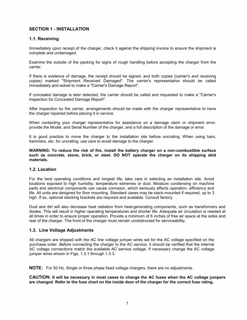
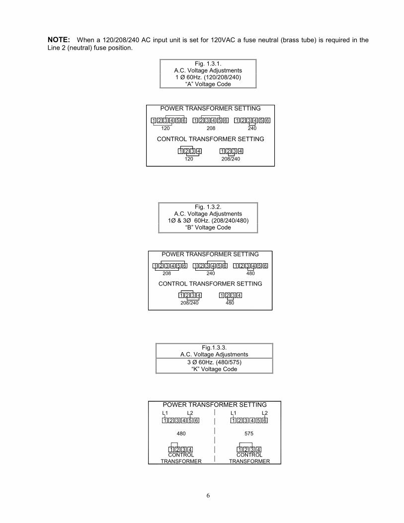
1.3. Line Voltage Adjustments All chargers are shipped with the AC line voltage jumper wires set for the AC voltage specified on the purchase order. Before connecting the charger to the AC service, it should be verified that the internal AC voltage connections match the available AC service voltage. If necessary change the AC voltage jumper wires shown in Figs. 1.3.1 through 1.3.3.
NOTE: For 50 Hz. Single or three phase fixed voltage chargers, there are no adjustments.
CAUTION: It will be necessary in most cases to change the AC fuses when the AC voltage jumpers are changed. Refer to the fuse chart on the inside door of the charger for the correct fuse rating.
6
575
POWER TRANSFORMER SETTING
480
L2 L2
1 2 3 4 5 6 1 2 3 4 5 6
L1 L1
1 2 3 4 1 32 4CONTROL
TRANSFORMER
CONTROL
TRANSFORMER
NOTE: When a 120/208/240 AC input unit is set for 120VAC a fuse neutral (brass tube) is required in the Line 2 (neutral) fuse position.
Fig. 1.3.1. A.C. Voltage Adjustments 1 Ø 60Hz. (120/208/240)
“A” Voltage Code
Fig. 1.3.2. A.C. Voltage Adjustments
1Ø & 3Ø 60Hz. (208/240/480) “B” Voltage Code
Fig.1.3.3. A.C. Voltage Adjustments
3 Ø 60Hz. (480/575) “K” Voltage Code

7
TABLE 1-1
Line Amperes Disconnect Switch Fuse Size Amps
000.0 - 02.5 30A 05 003.0 - 04.5 30A 07 005.0 - 07.5 30A 10 008.0 - 11.0 30A 15 011.5 - 15.5 30A 20 016.0 - 18.0 30A 25 018.5 - 22.0 30A 30 022.5 - 27.0 60A 35 027.5 - 32.0 60A 40 032.5 - 40.0 60A 50 040.5 - 48.0 60A 60 048.5 - 64.0 80A 80 065.0 - 80.0 100A 100 081.0 - 95.0 125A 125 096.0 - 125.0 150A 150
1.4. AC Service Requirements Follow local code requirements if they are different than the instructions in this manual. After checking the transformer connections as described in Paragraph 1.3, refer to Table 1-1, to determine the correct ratings for the AC cable, AC fuses, and AC service disconnect switch for the line amperes as listed on the nameplate of the charger for the available AC voltage For voltages up to 240, use a 240 volt disconnect switch. For voltages greater than 240 to 600, use a 600 volt disconnect switch.
• Two conductors and ground wire required for single phase.
• Three conductors and ground wire required for three-phase
1.5. Connecting AC Service to the Charger 1.5.1 Single-Phase Models Connect the AC service to the L1 and L2 terminals located at the end of the AC fuse block. Note: If the charger has been ordered with an AC input door-mounted disconnect switch, the AC input wires will be connected to the L1 and L3 terminals at the top of the switch body.
1.5.2 Three-Phase Models Connect the AC service to the L1, L2 and L3 terminals located at the end of the AC fuse block. Note: If the charger has been ordered with an AC input door-mounted disconnect switch, the AC input wires will be connected to the L1, L2 and L3 terminals at the top of the switch body.

8
1.6 Grounding the Charger
The charger must be grounded to the AC system ground for personnel safety. The green ground wire in the AC input wiring must be connected to the charger ground stud (identified by a green dot and ground symbol).
1.7 Battery Connector and Charging Cable Verify that the connectors on both the battery and the charger are attached so that the positive output terminal of the charger is connected to the positive battery terminal.
CAUTION: If the polarity is reversed, the DC fuse will blow. If in doubt, check the polarity with a DC voltmeter.
1.8 Charging Rate Adjustment Note: Charging rate adjustments may be necessary to compensate for locations of extreme AC line variation or may be used to tailor the charger output for aging batteries. The charging rate has been set at the factory; therefore, field adjustment should not be necessary. If there appears to be a charging rate problem, refer to the troubleshooting chart, Section 4. If it is necessary to either increase or decrease the charging rate, a rate adjustment terminal block is provided on the top rear of the transformer mounting bracket. Change only one step at a time and observe the effect on the battery before making a second change. The charging rate is increased by moving to the next higher tap setting in Table 1-2. The charging rate is decreased by moving to the next lower tap setting. No adjustments should be made without consulting the factory.
TABLE 1-2
CHARGING RATE ADJUSTMENTS
CONNECT RED JUMPER WIRE TO
CONNECT BLACK WIRE TO
OUTPUT
9 12 HIGHEST
9 11
9 10
9 8 NORMAL
12 11
12 10
12 9 LOWEST

9
SECTION 2 - OPERATION
2.1 046-0271 CONTROL
2.1.1 Operation The 046-0271 control is used in high frequency or ferro-resonant taper chargers to provide fully
automatic battery charging. The control has a charging profile that handles standard flooded lead-acid batteries. The charging profile, or algorithm, uniquely monitors the output current and voltage to optimally charge the battery, based on battery manufacturer’s recommendations.
The control offers several safeguards to protect the battery. If a wrong voltage battery is connected, the charger does not start and a Low-Battery-Voltage (F3) or High-Battery-Voltage (F4) message is displayed. While charging, if the battery voltage exceeds a profile-specific cut-off value, the charge terminates with an end on voltage message.
2.1.2 Normal Daily Charge When no battery is connected, the LED indicators are off and the LCD display shows ‘0A 0.00VC’. With
the auto-start feature enabled, connecting a battery to the charger causes it to begin a charge cycle. The charger first performs a self-diagnostic test to verify the control is working properly. During this time a lamp test is performed causing all display segments and indicators to light. This allows the operator to observe any defective segments or indicators. When the self-diagnostic is complete, the charge starts if no delay is set, and the yellow ‘Charging’ indicator lights. The display shows the charging amps and battery volts per cell along with a message to indicate the charger is in phase 1 of the charge cycle. If auto start is disabled, the display shows ‘CHARGER OFF’. Press STOP to manually start the charge.
When the battery is 80% charged, the charger starts phase 2 of the charge cycle.
When a charge is finished, the charger automatically turns off. The yellow ‘Charging’ indicator goes out. If cool down is enabled, the display shows the cool down time remaining. If cool down is disabled or the time has elapsed, the display shows ‘0A x.xxVC’ along with a message indicating the battery is ready and the green ‘Complete’ indicator lights.
Disconnecting the Battery
Warning: Risk of explosion. Do not disconnect the battery while the charger is running. Hydrogen gas produced
by the battery during charging can be ignited by arcing that occurs when the battery cable is disconnected.
If the battery must be disconnected before the end of the charge cycle, the charger should be turned off first. Press STOP, and verify the yellow ‘Charging’ indicator goes out. The LCD display shows ‘CHARGER OFF’. The battery may then be safely disconnected. If the green ‘Complete’ indicator is lit, the battery may be disconnected at any time.
10
2.1.3 Equalize Charge Over time batteries can develop inequalities in cell charge. This can lower the effective capacity of the
battery and shorten life. An equalizing charge re-balances the charge in the battery cells. Perform an equalize charge if any of the following conditions exist:
1. On flooded batteries the specific gravity of any cell at the end of charge is 20 points less than the average of all the cells.
2. The on-charge voltage of any cell at the end of charge is 20 millivolts less than the average of all the cells.
3. The battery has been stored for 30 days.
The 046-0271 control can perform an equalize automatically if auto equalize is enabled. Normal equalize consists of an additional 3 hour charge time at the end of a normal charge cycle. The 046-0271 control can also perform an equalize charge when requested manually. First connect the battery and allow the charge to start normally. Then press =. The display shows ‘=’ on the left side and the charge time is extended by 3 hours to allow the cells to equalize their charge.
The auto-equalize or manual equalize cycle can be cleared by pressing = while in the normal charge cycle. The ‘=’ indication on the display turns off. The next auto equalize charge occurs after the set number of charge cycles if auto equalize is enabled. If the set number of charge cycles have been completed, the charger attempts to equalize after the next charge cycle and continues to attempt to equalize until an equalize cycle has completed.
The default setting for automatic equalize is every 7 cycles. To change the number of charge cycles for automatic equalize, refer to the programming section.
2.1.4 Delayed Start The delayed-start feature allows the operator to delay starting the charge cycle. This might be desired to
reduce peak energy surcharges if the charger were ready to start during a peak energy period. The delay time could be set to keep the charger from starting until after the peak period ends.
To view or change the delayed start setting, refer to the programming section.
2.1.5 Auto- Refresh Charge
The 046-0271 control can provide an auto-refresh charge as long as the battery remains connected to the charger if enabled. If AC power is lost during the wait period, the control resumes from where it left off after power is restored. During the auto-refresh charge, the amp-hours and charge time are added to the original charge. The refresh charge consists of 30 minutes at the equalize current. To change the auto-refresh settings, refer to the programming section.

11
2.1.6 Viewing Charge Information
Additional charge information is available any time by pressing the INFO button. This information is retained after the battery is disconnected until the next battery is connected. After 20 seconds the display returns to the default display of amps and volts per cell. The following information can be viewed:
Parameter DISPLAY DESCRIPTION
Charger State XXXXXX Message describing charger state.
Amps CHARGER DC AMPS
AA: xxxA
Charger current in amps.
Volts/Cell BATTERY V/C
VC: x.xxVC
Battery voltage in volts per cell (v/c).
Amp Hours ACCUMULATED AH
AH: xxxxAH
Amp Hours returned for the current (or last) charge cycle.
Charge Time CHARGE TIME
TC: xx:xxHM
Charge time for the current (or last) charge cycle in hours and minutes.
Percent Return % AH RETURNED
PR: xxx%
Percent of Amp Hours returned as a function of battery AH rating.
Voltage BATTERY VOLTS
VV: xx.xV
Total battery voltage in volts.
End Current CHARGE END AMPS
EA: xxxA
End current for the last charge cycle (current amps if charging)
End Voltage CHARGE END VOLTS
EV: x.xxVC
End voltage for the last charge cycle (current voltage if charging)
Software SOFTWARE VERSION
SW: x.xx
Control software version
ꃀ@
12
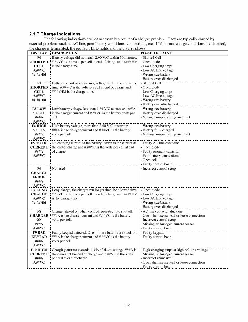
2.1.7 Charge Indications The following indications are not necessarily a result of a charger problem. They are typically caused by
external problems such as AC line, poor battery conditions, connections, etc. If abnormal charge conditions are detected,
the charge is terminated, the red fault LED lights and the display shows:
DISPLAY DESCRIPTION POSSIBLE CAUSE
F0
SHORTED
CELL
#.##VC
##:##HM
Battery voltage did not reach 2.00 V/C within 30 minutes.
#.##VC is the volts per cell at end of charge and ##:##HM
is the charge time.
- Shorted Cell
- Open diode
- Low Charging amps
- Low AC line voltage
- Wrong size battery
- Battery over-discharged
F1
SHORTED
CELL
#.##VC
##:##HM
Battery did not reach gassing voltage within the allowable
time. #.##VC is the volts per cell at end of charge and
##:##HM is the charge time.
- Shorted Cell
- Open diode
- Low Charging amps
- Low AC line voltage
- Wrong size battery
- Battery over-discharged
F3 LOW
VOLTS
###A
#.##VC
Low battery voltage, less than 1.60 V/C at start up. ###A
is the charger current and #.##VC is the battery volts per
cell.
- Wrong size battery
- Battery over-discharged
- Voltage jumper setting incorrect
F4 HIGH
VOLTS
###A
#.##VC
High battery voltage, more than 2.40 V/C at start up.
###A is the charger current and #.##VC is the battery
volts per cell.
- Wrong size battery
- Battery fully charged
- Voltage jumper setting incorrect
F5 NO DC
CURRENT
###A
#.##VC
No charging current to the battery. ###A is the current at
the end of charge and #.##VC is the volts per cell at end
of charge.
- Faulty AC line contactor
- Open diode
- Faulty resonant capacitor
- Poor battery connections
- Open cell
- Faulty control board
F6
CHARGE
ERROR
###A
#.##VC
Not used - Incorrect control setup
F7 LONG
CHARGE
#.##VC
##:##HM
Long charge, the charger ran longer than the allowed time.
#.##VC is the volts per cell at end of charge and ##:##HM
is the charge time.
- Open diode
- Low Charging amps
- Low AC line voltage
- Wrong size battery
- Battery over-discharged
F8
CHARGER
ON
###A
#.##VC
Charger stayed on when control requested it to shut off.
###A is the charger current and #.##VC is the battery
volts per cell.
- AC line contactor stuck on
- Open shunt sense lead or loose connection
- Incorrect control setup
- Missing or damaged current sensor
- Faulty control board
F9 BAD
KEYPAD
###A
#.##VC
Faulty keypad detected. One or more buttons are stuck on.
###A is the charger current and #.##VC is the battery
volts per cell.
- Faulty keypad
- Faulty control board
F10 HIGH
CURRENT
###A
#.##VC
Charging current exceeds 110% of shunt setting. ###A is
the current at the end of charge and #.##VC is the volts
per cell at end of charge.
- High charging amps or high AC line voltage
- Missing or damaged current sensor
- Incorrect shunt size
- Open shunt sense lead or loose connection
- Faulty control board

ꃀ@
13
Note: F3 and F4 clear automatically if the battery voltage falls within acceptable limits. All indications except F8, F9 and F10 can be cleared by disconnecting the battery. For F8, F9 and F10, correct the condition that caused the indication and disconnect the battery to clear the indication.
CAUTION: If F8 is showing, and the charger is providing current to the battery, remove AC power from the charger before disconnecting the battery.
2.1.8 F3 (Low Battery) Override If battery voltage is below 1.60 volts per cell the charger does not start automatically. If this is due to an
overly discharged battery of the correct voltage, the F3 indication can be manually overridden by pressing ‘STOP’ while the F3 message (Low Battery) displays.
2.1.9 Jumper Settings
CAUTION: Remove AC and DC power from the charger before changing any jumper settings. Refer to figure 2.1 for location of jumpers.
- Jumper J5 should be set to match the battery voltage. Volts 80V 72V 64V 48V 36V 24V 12V
1
SP2
1For non-standard battery voltages above 80V, the jumper is set on 12 and a resistor is installed in the
charger wire harness based on the following calculation: R = 1250 x (Nominal Battery Voltage) – 15000.
2For non-standard battery voltages between 12V and 80V, the jumper is set on SP and resistor R9 is installed
on the control based on the following calculation: R9 = 1250 x (Nominal Battery Voltage) – 15000.
- Jumper J4 is used to lock out several parameters in the programming mode. - Header J1 is used to select the charger type.
J4 J4
LOCKED UNLOCKED HF*FERRO
*J1 used for interface to HF module
J1 J1
CHARGER TYPEPARAMETER LOCKOUT
Caution: Placing jumpers on any other position on J1 or J4 may damage the control and voids the warranty.
14
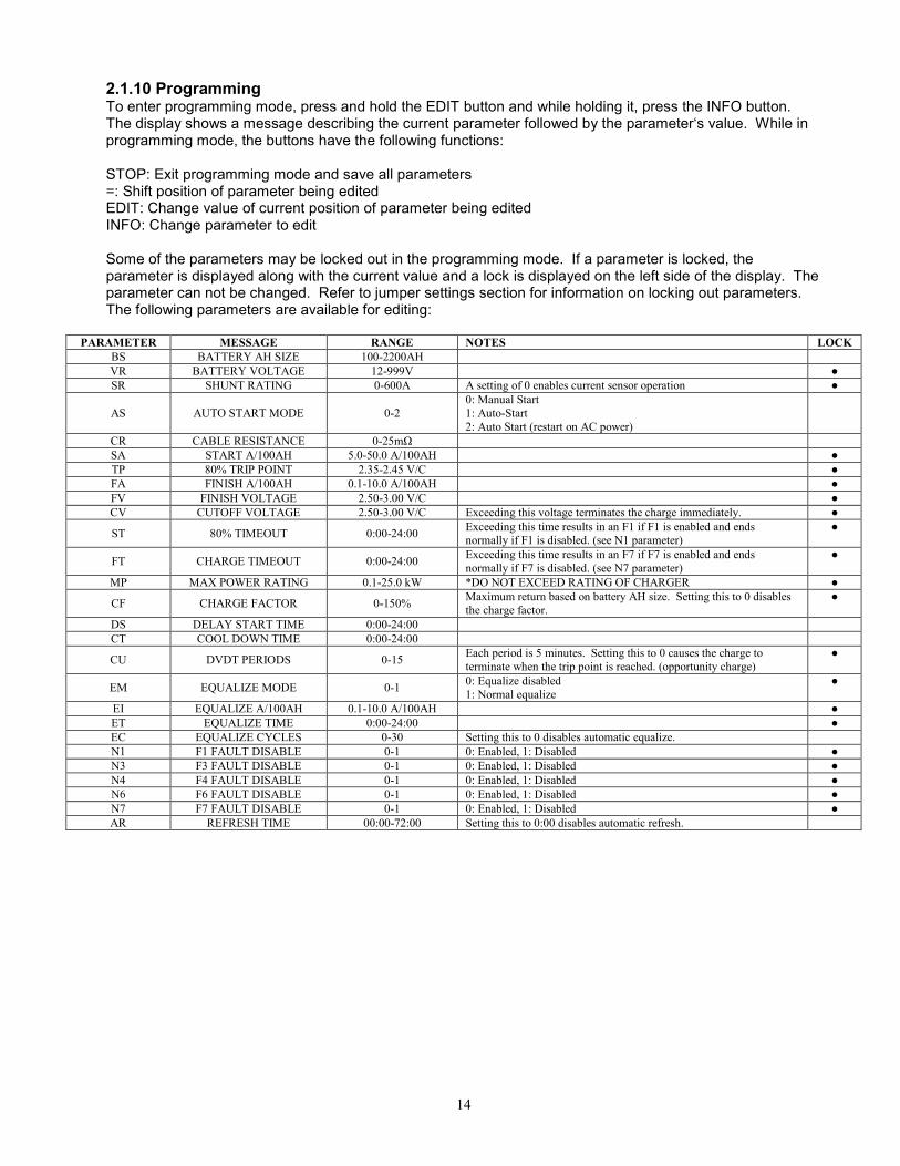
2.1.10 Programming To enter programming mode, press and hold the EDIT button and while holding it, press the INFO button. The display shows a message describing the current parameter followed by the parameter‘s value. While in programming mode, the buttons have the following functions: STOP: Exit programming mode and save all parameters =: Shift position of parameter being edited EDIT: Change value of current position of parameter being edited INFO: Change parameter to edit Some of the parameters may be locked out in the programming mode. If a parameter is locked, the parameter is displayed along with the current value and a lock is displayed on the left side of the display. The parameter can not be changed. Refer to jumper settings section for information on locking out parameters. The following parameters are available for editing:
PARAMETER MESSAGE RANGE NOTES LOCK
BS BATTERY AH SIZE 100-2200AH
VR BATTERY VOLTAGE 12-999V
SR SHUNT RATING 0-600A A setting of 0 enables current sensor operation
AS AUTO START MODE 0-2
0: Manual Start
1: Auto-Start
2: Auto Start (restart on AC power)
CR CABLE RESISTANCE 0-25mΩ
SA START A/100AH 5.0-50.0 A/100AH
TP 80% TRIP POINT 2.35-2.45 V/C
FA FINISH A/100AH 0.1-10.0 A/100AH
FV FINISH VOLTAGE 2.50-3.00 V/C
CV CUTOFF VOLTAGE 2.50-3.00 V/C Exceeding this voltage terminates the charge immediately.
ST 80% TIMEOUT 0:00-24:00 Exceeding this time results in an F1 if F1 is enabled and ends normally if F1 is disabled. (see N1 parameter)
FT CHARGE TIMEOUT 0:00-24:00 Exceeding this time results in an F7 if F7 is enabled and ends
normally if F7 is disabled. (see N7 parameter)
MP MAX POWER RATING 0.1-25.0 kW *DO NOT EXCEED RATING OF CHARGER
CF CHARGE FACTOR 0-150% Maximum return based on battery AH size. Setting this to 0 disables
the charge factor.
DS DELAY START TIME 0:00-24:00
CT COOL DOWN TIME 0:00-24:00
CU DVDT PERIODS 0-15 Each period is 5 minutes. Setting this to 0 causes the charge to
terminate when the trip point is reached. (opportunity charge)
EM EQUALIZE MODE 0-1 0: Equalize disabled
1: Normal equalize
EI EQUALIZE A/100AH 0.1-10.0 A/100AH
ET EQUALIZE TIME 0:00-24:00
EC EQUALIZE CYCLES 0-30 Setting this to 0 disables automatic equalize.
N1 F1 FAULT DISABLE 0-1 0: Enabled, 1: Disabled
N3 F3 FAULT DISABLE 0-1 0: Enabled, 1: Disabled
N4 F4 FAULT DISABLE 0-1 0: Enabled, 1: Disabled
N6 F6 FAULT DISABLE 0-1 0: Enabled, 1: Disabled
N7 F7 FAULT DISABLE 0-1 0: Enabled, 1: Disabled
AR REFRESH TIME 00:00-72:00 Setting this to 0:00 disables automatic refresh.

15
J2
J8
J6
J5
J7
VO
LT
S8
07
26
44
83
62
41
2S
PJ1
J4
Figure 2.1
16
SECTION 2 – OPERATION (continued)
2.2 046-0272 CONTROL
2.2.1 DESCRIPTION
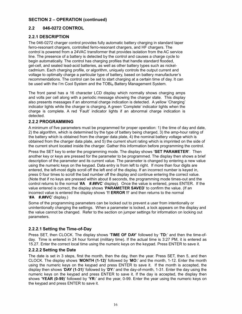
The 046-0272 charger control provides fully automatic battery charging in standard taper ferro-resonant chargers, controlled ferro-resonant chargers, and HF chargers. The control is powered from a 24VAC transformer that provides isolation from the AC service line. The presence of a battery is detected by the control and causes a charge cycle to begin automatically. The control has charging profiles that handle standard flooded, gel-cell, and sealed lead-acid batteries, as well as other battery types such as nickel-cadmium. Each charging profile, or algorithm, uniquely controls the output current and voltage to optimally charge a particular type of battery, based on battery manufacturer’s recommendations. The control can be set to start charging at a certain time of day. It can be used with the I’m Cool System and the TOBi® Battery Management System.
The front panel has a 16 character LCD display which normally shows charging amps and volts per cell along with a periodic message showing the charger state. This display also presents messages if an abnormal charge indication is detected. A yellow ‘Charging’ indicator lights while the charger is charging. A green ‘Complete’ indicator lights when the charge is complete. A red ‘Fault’ indicator lights if an abnormal charge indication is detected.
2.2.2 PROGRAMMING
A minimum of five parameters must be programmed for proper operation: 1) the time of day and date, 2) the algorithm, which is determined by the type of battery being charged, 3) the amp-hour rating of the battery which is obtained from the charger data plate, 4) the nominal battery voltage which is obtained from the charger data plate, and 5) the current shunt rating which is imprinted on the side of the current shunt located inside the charger. Gather this information before programming the control.
Press the SET key to enter the programming mode. The display shows ‘SET PARAMETER’. Then another key or keys are pressed for the parameter to be programmed. The display then shows a brief description of the parameter and its current value. The parameter is changed by entering a new value using the numeric keys on the keypad. Data entry is from left to right. If more than four digits are entered, the left-most digits scroll off the left end of the display. If an incorrect number is keyed in, press 0 four times to scroll the bad number off the display and continue entering the correct value. (Note that if no keys are pressed within about 8 seconds, the programming mode times-out and the control returns to the normal ‘#A #.##VC’ display). Once the value is entered, press ENTER. If the value entered is correct, the display shows ‘PARAMETER SAVED’ to confirm the value. (If an incorrect value is entered the display shows ‘!! ERROR !!‘ and then returns to the normal ‘#A #.##VC’ display.)
Some of the programming parameters can be locked out to prevent a user from intentionally or unintentionally changing the settings. When a parameter is locked, a lock appears on the display and the value cannot be changed. Refer to the section on jumper settings for information on locking out parameters.
2.2.2.1 Setting the Time-of-Day
Press SET, then CLOCK. The display shows ‘TIME OF DAY’ followed by ‘TD:’ and then the time-of-day. Time is entered in 24 hour format (military time). If the actual time is 3:27 PM, it is entered as 15.27. Enter the correct local time using the numeric keys on the keypad. Press ENTER to save it.
2.2.2.2 Setting the Date
The date is set in 3 steps, first the month, then the day, then the year. Press SET, then 5, and then CLOCK. The display shows ‘MONTH (1-12)’ followed by ‘MO:’ and the month, 1-12. Enter the month using the numeric keys on the keypad and press ENTER to save it. If the month is accepted, the display then shows ‘DAY (1-31)’ followed by ‘DY:’ and the day-of-month, 1-31. Enter the day using the numeric keys on the keypad and press ENTER to save it. If the day is accepted, the display then shows ‘YEAR (0-99)’ followed by ‘YR:’ and the year, 0-99. Enter the year using the numeric keys on the keypad and press ENTER to save it.
17
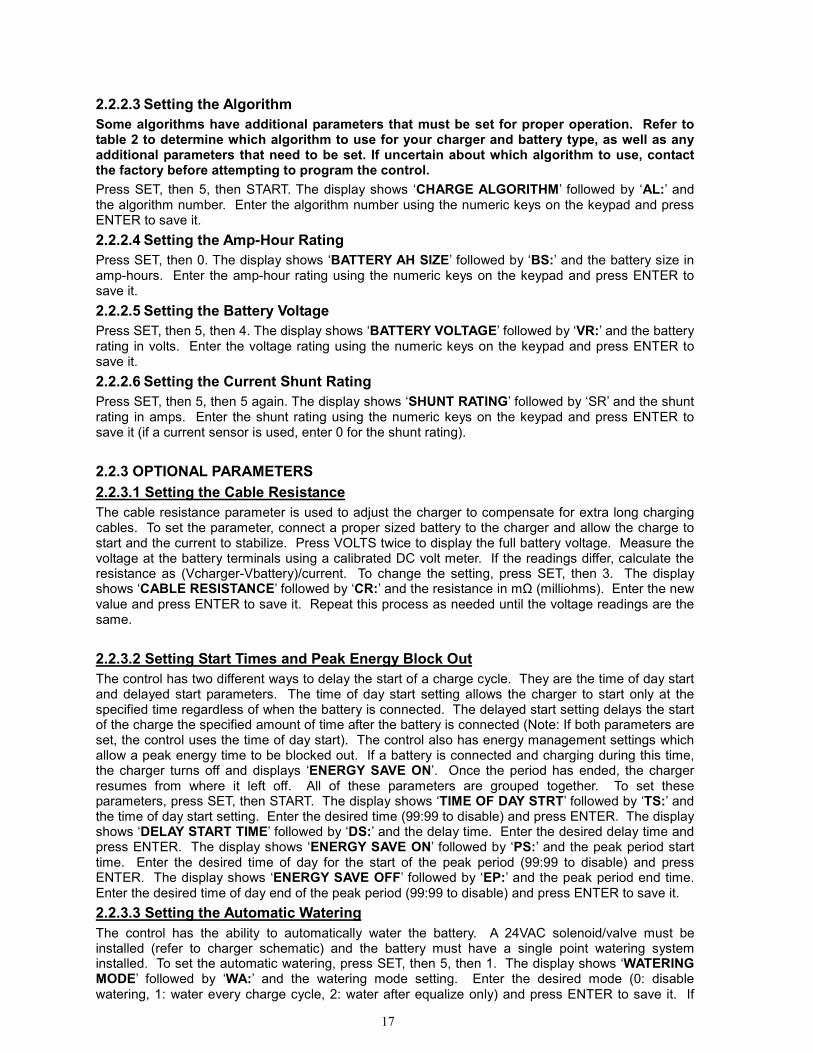
2.2.2.3 Setting the Algorithm
Some algorithms have additional parameters that must be set for proper operation. Refer to table 2 to determine which algorithm to use for your charger and battery type, as well as any additional parameters that need to be set. If uncertain about which algorithm to use, contact the factory before attempting to program the control.
Press SET, then 5, then START. The display shows ‘CHARGE ALGORITHM’ followed by ‘AL:’ and the algorithm number. Enter the algorithm number using the numeric keys on the keypad and press ENTER to save it.
2.2.2.4 Setting the Amp-Hour Rating
Press SET, then 0. The display shows ‘BATTERY AH SIZE’ followed by ‘BS:’ and the battery size in amp-hours. Enter the amp-hour rating using the numeric keys on the keypad and press ENTER to save it.
2.2.2.5 Setting the Battery Voltage
Press SET, then 5, then 4. The display shows ‘BATTERY VOLTAGE’ followed by ‘VR:’ and the battery rating in volts. Enter the voltage rating using the numeric keys on the keypad and press ENTER to save it.
2.2.2.6 Setting the Current Shunt Rating
Press SET, then 5, then 5 again. The display shows ‘SHUNT RATING’ followed by ‘SR’ and the shunt rating in amps. Enter the shunt rating using the numeric keys on the keypad and press ENTER to save it (if a current sensor is used, enter 0 for the shunt rating).
2.2.3 OPTIONAL PARAMETERS
2.2.3.1 Setting the Cable Resistance
The cable resistance parameter is used to adjust the charger to compensate for extra long charging cables. To set the parameter, connect a proper sized battery to the charger and allow the charge to start and the current to stabilize. Press VOLTS twice to display the full battery voltage. Measure the voltage at the battery terminals using a calibrated DC volt meter. If the readings differ, calculate the resistance as (Vcharger-Vbattery)/current. To change the setting, press SET, then 3. The display shows ‘CABLE RESISTANCE’ followed by ‘CR:’ and the resistance in mΩ (milliohms). Enter the new value and press ENTER to save it. Repeat this process as needed until the voltage readings are the same.
2.2.3.2 Setting Start Times and Peak Energy Block Out
The control has two different ways to delay the start of a charge cycle. They are the time of day start and delayed start parameters. The time of day start setting allows the charger to start only at the specified time regardless of when the battery is connected. The delayed start setting delays the start of the charge the specified amount of time after the battery is connected (Note: If both parameters are set, the control uses the time of day start). The control also has energy management settings which allow a peak energy time to be blocked out. If a battery is connected and charging during this time, the charger turns off and displays ‘ENERGY SAVE ON’. Once the period has ended, the charger resumes from where it left off. All of these parameters are grouped together. To set these parameters, press SET, then START. The display shows ‘TIME OF DAY STRT’ followed by ‘TS:’ and the time of day start setting. Enter the desired time (99:99 to disable) and press ENTER. The display shows ‘DELAY START TIME’ followed by ‘DS:’ and the delay time. Enter the desired delay time and press ENTER. The display shows ‘ENERGY SAVE ON’ followed by ‘PS:’ and the peak period start time. Enter the desired time of day for the start of the peak period (99:99 to disable) and press ENTER. The display shows ‘ENERGY SAVE OFF’ followed by ‘EP:’ and the peak period end time. Enter the desired time of day end of the peak period (99:99 to disable) and press ENTER to save it.
2.2.3.3 Setting the Automatic Watering
The control has the ability to automatically water the battery. A 24VAC solenoid/valve must be installed (refer to charger schematic) and the battery must have a single point watering system installed. To set the automatic watering, press SET, then 5, then 1. The display shows ‘WATERING MODE’ followed by ‘WA:’ and the watering mode setting. Enter the desired mode (0: disable watering, 1: water every charge cycle, 2: water after equalize only) and press ENTER to save it. If

18
watering is enabled, the display shows ‘WATERING CYCLES’ followed by ‘WC:’ and the number of watering cycles. Enter the desired number of cycles (each cycle is 15 seconds on and 45 seconds off) and press ENTER to save it.
2.2.3.4 Setting Automatic Equalize
The control has the ability to automatically equalize the battery based on the number of cycles or on a specific day of the week. The equalize cycle can also be delayed a specified amount of time. To set the automatic equalize parameters, press SET, then 5, then 3. The display shows ‘EQUALIZE CYCLES’ followed by ‘EC:’ and the number of cycles before equalize occurs. Enter the desired number of cycles (0 to disable) and press ENTER. The display shows ‘EQUALIZE DAY’ followed by ‘ED:’ and the equalize day. Enter the desired day (0 to disable, 1-7 for Sunday-Saturday) and press ENTER. The display show ‘DELAYED EQUALIZE’ followed by ‘DE:’ and the equalize delay time. Enter the desired delay time and press ENTER to save it.
2.2.3.5 Setting Cool Down Time
The control has the ability to set a cool down time to allow the battery to cool before it is used or to display the elapsed time to determine the coolest battery. To set the cool down time, press SET, then 5, then 7. The display shows ‘COOL DOWN TIME’ followed by ‘CT:’ and the cool down time. Enter the desired time and press ENTER. If a time is set, the display shows ‘COUNT DIRECTION’ followed by ‘TU:’ and the direction. Enter the desired setting (0: count down, 1: count up) and press ENTER to save it. If the direction is set to count down, the battery ready light does not come on until the cool down time has elapsed. If the direction is set to count up, the battery ready light comes on when the charge is complete and the elapsed time since the charge completed is displayed.
2.2.3.6 Setting Automatic Refresh
To set the automatic refresh interval, press SET, then 5, then 8. The display shows ‘REFRESH TIME’ followed by ‘AR:’ and the refresh interval time. Enter the desired interval for automatic refresh (00:00 to disable) and press ENTER. A refresh consists of 30 minutes of charging at the equalize current.
2.2.3.7 Setting Charger Alerts
To set the alert parameter, press SET, then 5, then 0. The display shows ‘ALERT ENABLE’ followed by ‘AO:’ and the alert setting. Enter the desired setting (0:disable alerts, 1:enable alerts) and press ENTER. The display shows ‘ALERT INTERVAL’ followed by ‘AI:’ and the alert interval in seconds. Enter the desired setting and press ENTER. With alerts enabled, the control displays a message describing the charger state at the set interval.
2.2.3.8 Setting Automatic Start Mode
To set the automatic start mode, press SET, then STOP. The display shows ‘AUTO START MODE’ followed by ‘AS:’ and the automatic start setting. Enter the desired setting (0: manual start, 1:auto start, 2:auto start on AC) and press ENTER. If manual start is set, the charger never starts automatically. When the battery is connected, the display shows ‘CHARGER OFF’. Press STOP to manually start the charge. Also, in manual start mode the charger does not begin a refresh or automatic equalize cycle once the charger has turned off. If auto start on AC is set, the charger begins a new charge cycle whenever AC power is removed and restored to the charger. This is useful in applications where the charger is permanently connected to the battery and a charge cycle is initiated by plugging in the charger AC power cord.
2.2.4 Setting the Other Parameters
If the charger is part of an I’m Cool system or the TOBi® Battery Management System then the charger identifier (ID) must be set. This and other additional parameters are programmed in a manner similar to that above. Table 1 describes the parameters and key-strokes used for programming them. When more than one parameter is in the same row of the table, the control automatically sequences through the additional parameters.
19
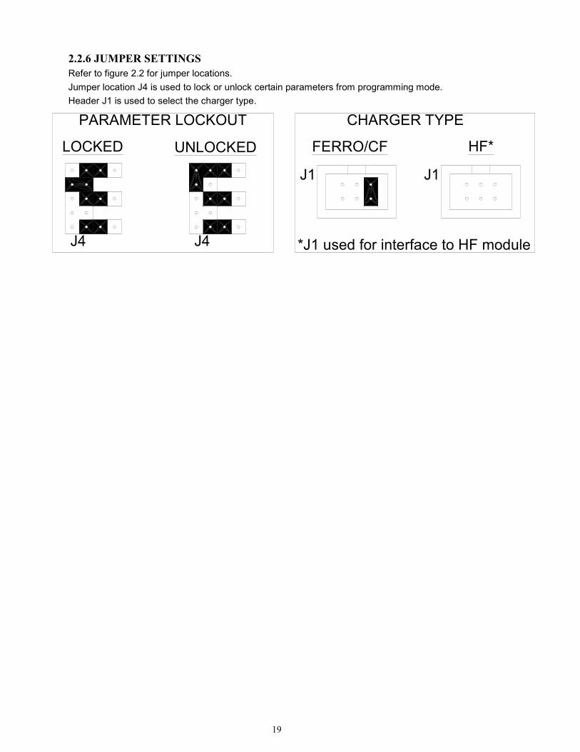
2.2.6 JUMPER SETTINGS
Refer to figure 2.2 for jumper locations.
Jumper location J4 is used to lock or unlock certain parameters from programming mode.
Header J1 is used to select the charger type.
J4
LOCKED UNLOCKED
J4
J1
PARAMETER LOCKOUT CHARGER TYPE
FERRO/CF HF*
J1
*J1 used for interface to HF module

Page 20 of 34
Table 1. Programmable Parameter List
First Key Second Key Third Key Parameter(s) Description Allowable Settings Default Notes Locked
SET SET none none n/a n/a n/a
SET 1 (AMPS) None SA Set Amps 0.0-100.0 (A/100Ah) 0.0 3
SET 2 (VOLTS) None SV Set Volts 0.0-999.9 (V) 0.0 3
SET 3 (AH) None CR Cable Resistance 0-25 (mΩ) 2
SET START None
TS
DS
PS EP
Time of Day Start
Delayed Start
Energy Management Peak Start Energy Management Peak End
00:00-23:59; 99:99 (disable)
00:00-24:00 (hh:mm)
00:00-23:59; 99:99 (disable) 00:00-23:59; 99:99 (disable)
99:99
00:00
99:99 99:99
SET 4 (TOC) None ST Set Charge Time 00:00-99:99 (hh:mm) (99:99 runs forever) 00:00 3
SET 5 SET none n/a n/a n/a
SET 5 1 (AMPS) WA Watering Enable 0 (disable); 1 (every cycle); 2 (after equalize) 0
WC Watering Cycles 0-60 (15s ON/ 45s OFF) 0
SET 5 2 (VOLTS) CV Charge Cutoff Voltage 1.40-3.55 (v/c) 2.80 2
SET 5 3 (AH) EC Equalize by Number of Charges 0-100 7 2
ED Equalize by Day 0(disable); 1-7(Sun-Sat) 0 2
DE Equalize Delay Time 00:00-24:00 (hh:mm) 00:00 2
SET 5 START AL Charge Algorithm 1-17 n/a 1
SET 5 4 (TOC) VR Battery Voltage Rating 12-999 (V) 24
SET 5 5 (VER.) SR Charger Shunt Rating 0(current sensor); 50-600 (A) 200
SET 5 6 (I.D.) EM Equalize Mode 0 (None); 1(Normal) 1 2
EI Equalize Current 0.1-10.0 (A/100Ah) 5.0 2
SET 5 CLOCK MO Month 1-12 (Jan-Dec) n/a
DY Day (of the month) 1-31 n/a
YR Year 0-99 (years since 2000) n/a
SET 5 7 (TEMP) CT
TU
Cool Down Time
Count Up/Down
00:00-24:00 (hh:mm)
0(count down); 1(count up)
0:00
0
SET 5 8 (% RET.) AR Auto Refresh Time 00:00-72:00 (hh:mm) (0:00 disables) 0:00
SET 5 9 (80%) TP DVDT Trip Point 1.20-2.55 (v/c) 2.38 2
SET 5 ENTER N2 F2 Indication Disable 0 (enable); 1 (disable) 1 2
N3 F3 Indication Disable 0 (enable); 1 (disable) 0 2
N4 F4 Indication Disable 0 (enable); 1 (disable) 0 2
N6 F6 Indication Disable 0 (enable); 1 (disable) 0 2
SET 5 = ET Equalize Time 00:00-24:00 (hh:mm) 3:00 2
SET 5 0 (TEST) AO Alert On Enable 0 (disable); 1 (enable) 1
AI Alert Interval 10-60 (s) 60
SET 5 STOP BC Battery Module Comm. Enable 0 (disable); 1 (enable); 2 (enable and upload alg.) 0
SET 6 (I.D.) None ID Charger I.D. (for Tobi or I'm Cool) 1-1000; 9999 9999
SET CLOCK none TD Time of Day (Clock) 00:00-23:59 (hh:mm) n/a
SET 7 (TEMP) none OT OK to Charge Temp 0-185 (˚F) (0 disables sensor) 0 2
LT NT
Low Charge Temp No Charge Temp
0-185 (˚F) 0-185 (˚F)
115 125
2 2
SET 8 (% RET.) none CF Charge Back Factor 0-150 (% of AH rating) (0 disables) 120
SET 9 (80%) none MP Max Power Rating 0.1-25.0 (kW) 3.3 2
SET ENTER none custom alg. 1,2,3
SET = none CU DVDT Periods 0-15 (5 minutes each) 5
SET 0 (TEST) none BS Battery AH Rating 100-2200 (Ah) 0
SET STOP none AS Auto Start Mode 0 (manual start); 1 (auto start); 2 (auto start on ac) 1
Notes:
1. The Algorithm is set for the particular charger and battery type. If you are unsure of which algorithm to use, consult factory before setting.
2. These parameters are part of the algorithm. Any changes made to these are overwritten whenever the algorithm parameter is set.
3. These parameters are only used for certain algorithms. Consult the factory before changing any unfamiliar parameters.
ފ
Page 21 of 34
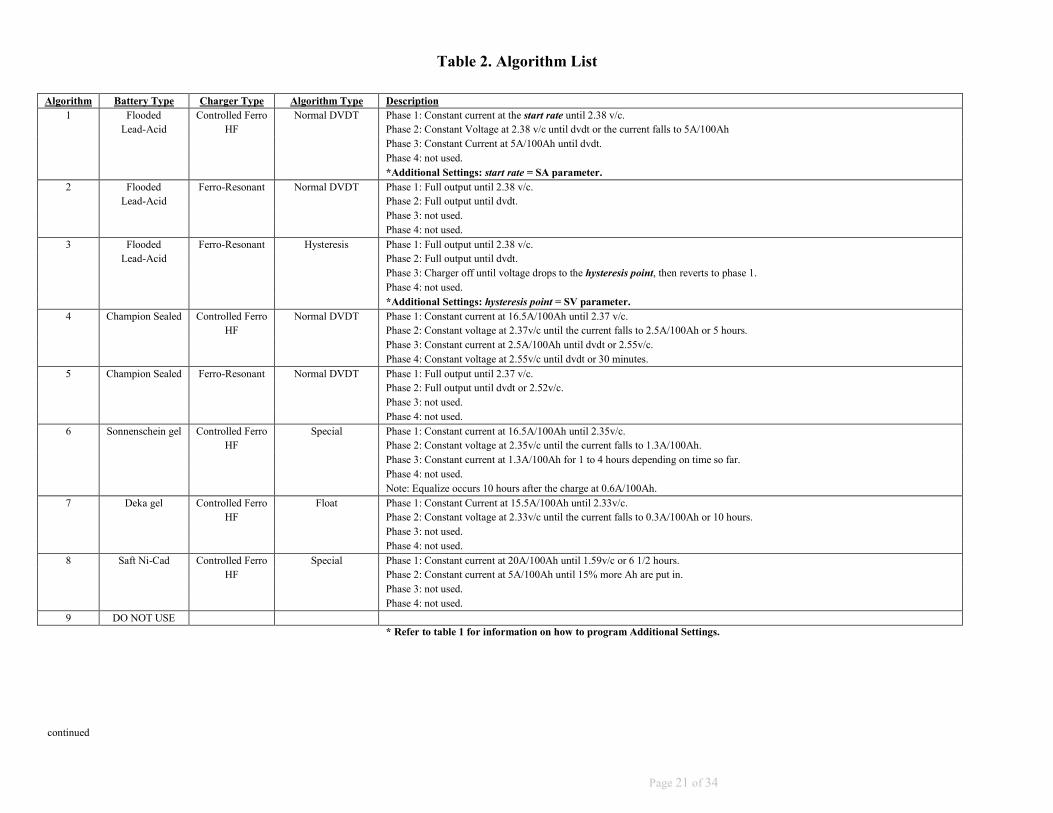
Table 2. Algorithm List
Algorithm Battery Type Charger Type Algorithm Type Description
1 Flooded Controlled Ferro Normal DVDT Phase 1: Constant current at the start rate until 2.38 v/c.
Lead-Acid HF Phase 2: Constant Voltage at 2.38 v/c until dvdt or the current falls to 5A/100Ah
Phase 3: Constant Current at 5A/100Ah until dvdt.
Phase 4: not used.
*Additional Settings: start rate = SA parameter.
2 Flooded Ferro-Resonant Normal DVDT Phase 1: Full output until 2.38 v/c.
Lead-Acid Phase 2: Full output until dvdt.
Phase 3: not used.
Phase 4: not used.
3 Flooded Ferro-Resonant Hysteresis Phase 1: Full output until 2.38 v/c.
Lead-Acid Phase 2: Full output until dvdt.
Phase 3: Charger off until voltage drops to the hysteresis point, then reverts to phase 1.
Phase 4: not used.
*Additional Settings: hysteresis point = SV parameter.
4 Champion Sealed Controlled Ferro Normal DVDT Phase 1: Constant current at 16.5A/100Ah until 2.37 v/c.
HF Phase 2: Constant voltage at 2.37v/c until the current falls to 2.5A/100Ah or 5 hours.
Phase 3: Constant current at 2.5A/100Ah until dvdt or 2.55v/c.
Phase 4: Constant voltage at 2.55v/c until dvdt or 30 minutes.
5 Champion Sealed Ferro-Resonant Normal DVDT Phase 1: Full output until 2.37 v/c.
Phase 2: Full output until dvdt or 2.52v/c.
Phase 3: not used.
Phase 4: not used.
6 Sonnenschein gel Controlled Ferro Special Phase 1: Constant current at 16.5A/100Ah until 2.35v/c.
HF Phase 2: Constant voltage at 2.35v/c until the current falls to 1.3A/100Ah.
Phase 3: Constant current at 1.3A/100Ah for 1 to 4 hours depending on time so far.
Phase 4: not used.
Note: Equalize occurs 10 hours after the charge at 0.6A/100Ah.
7 Deka gel Controlled Ferro Float Phase 1: Constant Current at 15.5A/100Ah until 2.33v/c.
HF Phase 2: Constant voltage at 2.33v/c until the current falls to 0.3A/100Ah or 10 hours.
Phase 3: not used.
Phase 4: not used.
8 Saft Ni-Cad Controlled Ferro Special Phase 1: Constant current at 20A/100Ah until 1.59v/c or 6 1/2 hours.
HF Phase 2: Constant current at 5A/100Ah until 15% more Ah are put in.
Phase 3: not used.
Phase 4: not used.
9 DO NOT USE
* Refer to table 1 for information on how to program Additional Settings.
continued

7
Page 22 of 34
10 Any Controlled Ferro Shop Charger Phase 1: Constant current at the start rate until the float voltage is reached or for the total run time.
HF Phase 2: Constant voltage at the float voltage for the remainder of the total run time.
Phase 3: not used.
Phase 4: not used.
*Additional Settings: start rate = SA parameter.
float voltage = SV parameter.
total run time = ST parameter.
11 Geltec/Crown gel Controlled Ferro Special Phase 1: Constant current at 16A/100Ah until 2.40v/c.
HF Phase 2: Constant voltage at 2.40v/c until the current falls to 1.5A/100Ah or 6 hours.
Phase 3: Constant current at 1.5A/100Ah for the remainder of the 6 hours from phase 2.
Phase 4: not used.
12 Flooded Controlled Ferro AGV Trickle Charge Phase 1: Constant current at the start rate until 2.40v/c.
Lead-Acid HF Phase 2: Constant voltage at 2.40v/c until the current falls to 1A/100Ah or dvdt.
Phase 3: Constant current at 4.5A/100Ah until 2.65v/c or 3 hours if manual equalize selected.
Phase 4: Constant voltage at 2.25v/c as long as the battery is connected.
*Additional Settings: start rate = SA parameter.
13 Douglas VRLA Controlled Ferro Special Phase 1: Constant current at 16A/100Ah until 2.40v/c.
HF Phase 2: Constant voltage at 2.40v/c until the current falls to 3A/100Ah or dvdt.
Phase 3: Constant current at 3A/100Ah until dvdt or 2.70v/c.
Phase 4: Constant voltage at 2.70v/c until dvdt.
14 n/a Any Factory Test Phase 1: Full output for 1 minute.
Phase 2: Constant current at maximum regulation point for 1 minute.
Phase 3: Constant current at minimum regulation point for 1 minute.
Phase 4: Minimum output for 1 minute.
15
Flooded Controlled Ferro Opportunity Charge Phase 1: Constant current at the start rate until 2.38 v/c.
Lead-Acid HF Phase 2: Off until the time of day reaches the set time.
Phase 3: Constant Voltage at 2.38 v/c until dvdt or the current falls to 5A/100Ah.
Phase 4: Constant Current at 5A/100Ah until dvdt.
*Additional Settings: start rate = SA parameter.
set time = ST parameter.
16 Flooded Ferro-Resonant Opportunity Charge Phase 1: Full output until 2.38 v/c.
Lead-Acid Phase 2: Off until the time of day reaches the set time.
Phase 3: Full output until dvdt.
Phase 4: not used.
*Additional Settings: set time = ST parameter.
17
Exide Element Controlled Ferro Special Phase 1: Constant current at 15.5A/100Ah until 2.37v/c.
HF Phase 2: Constant voltage at 2.37v/c until the current falls to 2A/100Ah or dvdt or 3.5 hours.
Phase 3: Constant current at 2A/100Ah until dvdt or the remainder of the 3.5 hours from phase 2.
Phase 4: not used.
18 Lithium Controlled Ferro Special Phase 1: Constant current at the start rate until 4.20 v/c.
HF Phase 2: Constant voltage at 4.20v/c until the current falls to 3A/100Ah or dvdt.
Phase 3: not used.
Phase 4: not used.
*Additional Settings: start rate = SA parameter.
* Refer to table 1 for information on how to program Additional Settings.
Table 2. Algorithm List Continued.
23
2.2.7 OPERATION
If alert messages are turned on, periodically a message shows for about 2 seconds in the display. With no battery connected, the control displays ‘0A 0.00VC’, and a ‘FERRO MAGNETICS’ alert is shown. When a battery is connected, a lamp test is performed. The charge begins, the yellow CHARGING indicator lights and the display shows ‘CHARGE PHASE 1’ periodically along with the charging amps and battery v/c. If equalize is active, an ‘=’ appears on the left side of the display to indicate an equalizing charge.
When phase 1 is completed, the charger starts phase 2 of the charge cycle. The display shows ‘CHARGE PHASE 2’ along with the charging amps and battery v/c. Depending on the charger and battery type, the charger may utilize up to 4 phases to complete a charge.
During the equalize portion of the charge cycle the display shows ‘EQUALIZING’ periodically along with the charging amps and battery v/c.
When a charge is finished, the charger automatically turns off. The display shows ‘BATTERY READY’ and the green COMPLETE indicator lights. The battery may then be disconnected at any time.
2.2.7.1 EQUALIZE CHARGE
Over time batteries can develop inequalities in cell charge. This can lower the effective capacity of the battery and shorten life. An equalizing charge re-balances the charge in the battery cells. Perform an equalize charge if any of the following conditions exist:
1. On flooded batteries the specific gravity of any cell at the end of charge is 20 points less than the average of all the cells.
2. The on-charge voltage of any cell at the end of charge is 20 millivolts less than the average of all the cells.
3. The battery has been stored for 30 days.
The control can perform an equalize automatically based on the number of charge cycles or on a specific day of the week. Normal equalize consists of an additional 3 hour charge time at the end of a normal charge cycle.
The control is set at the factory to perform a normal equalize every 7 charging cycles for flooded lead-acid batteries.
The control can also perform an equalize charge when requested manually. Press the = key. An ‘=’ appears on the left side of the display indicating an equalize charge for the current charge. If no battery is connected, the equalize occurs on the next charge cycle to allow the cells to equalize their charge.
The auto-equalize or manual equalize charge can be cleared by pressing the = key again. The next auto equalize charge occurs after the programmed number of charge cycles.

炰ތ
24
2.2.7.2 THERMAL SENSOR OPERATION
The control has the ability to read the battery temperature with an optional thermal sensor. In order for the sensor to function properly, it must be enabled in the control. This is accomplished by setting the ‘OK to charge temp’ (OT) parameter to a non-zero value (see table 1). This value indicates the maximum temperature that allows the charge to start. If the battery is above this temperature when it is connected, the control displays the temperature and waits for the battery to cool down before starting the charge.
If the thermal sensor is enabled and is missing or damaged, the control displays an F11 indication when the battery is connected.
The ‘Low charge temp’ (LT) parameter indicates the temperature at which the charge current is reduced to limit the temperature rise of the battery. The current is reduced proportional to the amount the battery temperature exceeds the limit.
The ‘No charge temp’ (NT) parameter indicates the temperature at which the charge is terminated. If this temperature is reached during charge, the charger shuts down and displays an F2 indication.
Refer to the battery manufacturers recommendations before setting these parameters.
If the thermal sensor is enabled, the battery voltage milestones on charge (trip point, cutoff, etc.) are compensated by 2.5mV/C per degree F (1.5mV/C per degree F for NiCad) above or below 77 degrees F. If the temperature is below 77 degrees, the voltage is adjusted up and if the temperature is above 77 degrees, the voltage is adjusted down.
2.2.7.3 TOBI® PI OPERATION
The control has the ability to communicate with a Tobi® PI battery module. In order for communication to occur, it has to be enabled in the control. This is accomplished by setting the ‘BC’ parameter (see table 1).
Setting the BC parameter to 0 disables communication.
Setting the BC parameter to 1 enables normal communication. While the battery is connected to the charger, information is transferred between the charger and the Tobi® PI on the battery including the battery temperature. In order for the charger to utilize the temperature, the temperature sensor must also be enabled. Refer to the preceding section on thermal sensor operation.
Setting the BC parameter to 2 enables normal communication as well as algorithm upload. In addition to the information transferred during normal mode, the charger also uploads and utilizes a charge algorithm from the Tobi® PI on the battery. This can be useful if multiple battery types or AH sizes are used on the same charger. Refer to the Tobi® PI manual for instructions on setting the charge algorithm. Note: If the communication between the charger and Tobi® PI fails, the charger utilizes its own algorithm settings to charge the battery.

25
2.2.7.4 CHARGE INDICATIONS
The following indications are not necessarily a result of a charger problem. They are typically caused by external problems such as AC line, poor battery conditions, connections, etc. If abnormal charge conditions are detected, the charge is terminated, the red FAULT indicator lights and the display shows the code:
DISPLAY DESCRIPTION POSSIBLE CAUSE
F0 SHORTED
CELL
#.##VC
##:##HM
Battery voltage did not reach 2.00 V/C within 30
minutes. #.##VC is the volts per cell at end of
charge and ##:##HM is the charge time.
- Shorted Cell
- Open diode
- Low Charging amps
- Low AC line voltage
- Wrong size battery
- Battery over-discharged
F1 SHORTED
CELL
#.##VC ##:##HM
Battery did not reach gassing voltage within the
allowable time. #.##VC is the volts per cell at end
of charge and ##:##HM is the charge time.
- Shorted Cell
- Open diode
- Low Charging amps
- Low AC line voltage
- Wrong size battery
- Battery over-discharged
F2 HOT
BATTERY
###°F #.##VC
Hot battery. The battery exceeded the NT
temperature. ###°F is the battery temperature and
#.##VC is the volts per cell at end of charge.
- Battery is overheated
- Damaged thermal sensor
- Faulty control board
F3 LOW VOLTS
###A #.##VC
Low battery voltage, less than 1.60 V/C at start up.
###A is the charger current and #.##VC is the
battery volts per cell.
- Wrong size battery
- Battery over-discharged
- Voltage jumper setting incorrect
F4 HIGH VOLTS
###A #.##VC
High battery voltage, more than 2.40 V/C at start
up. ###A is the charger current and #.##VC is the
battery volts per cell.
- Wrong size battery
- Battery fully charged
- Voltage jumper setting incorrect
F5 NO DC
CURRENT
###A #.##VC
No charging current to the battery. ###A is the
current at the end of charge and #.##VC is the volts
per cell at end of charge.
- Faulty AC line contactor
- Open diode
- Faulty resonant capacitor
- Poor battery connections
- Open cell
- Faulty control board
F6 CHARGE
ERROR
###A #.##VC
Charger current or voltage not what was requested
by control. ###A is the current at the end of charge
and #.##VC is the volts per cell at end of charge.
- Incorrect control setup
- Poor battery connections or open Cell
- Faulty HF module
- Faulty adapter board or cable
- Faulty control board
F7 LONG
CHARGE
#.##VC ##:##HM
Long charge, the charger ran longer than the
allowed time. #.##VC is the volts per cell at end of
charge and ##:##HM is the charge time.
- Open diode
- Low Charging amps
- Low AC line voltage
- Wrong size battery
- Battery over-discharged
F8 CHARGER
ON
###A #.##VC
Charger stayed on when control requested it to shut
off. ###A is the charger current and #.##VC is the
battery volts per cell.
- AC line contactor stuck on
- Open shunt sense lead or loose connection
- Incorrect control setup
- Missing or damaged current sensor
- Faulty control board
F9 BAD
KEYPAD
###A #.##VC
Faulty keypad detected. One or more buttons are
stuck on. ###A is the charger current and #.##VC is
the battery volts per cell.
- Faulty keypad
- Faulty control board
F10 HIGH
CURRENT
###A #.##VC
Charging current exceeds 110% of shunt setting.
###A is the current at the end of charge and #.##VC
is the volts per cell at end of charge.
- High charging amps or high AC line voltage
- Missing or damaged current sensor
- Incorrect shunt size
- Open shunt sense lead or loose connection
- Faulty control board
F11
TEMP
ERROR
255°F #.##VC
No thermal sensor. #.##VC is the battery volts per
cell.
- Missing or damaged thermal sensor
- Thermal sensor enabled when not installed
- Faulty control board
7
26
Note: F3 and F4 clear automatically if the battery voltage falls within acceptable limits. All indications except F8, F9 and F10 can be cleared by disconnecting the battery. For F8, F9 and F10, correct the condition that caused the indication and disconnect the battery to clear the indication.
CAUTION: If F8 indication is showing, and the charger is providing current to the battery, remove AC power from the charger before disconnecting the battery.
2.2.7.5 F3 (LOW BATTERY) OVERRIDE If battery voltage is below 1.6 volts per cell the charger does not start automatically. If this is due to an overly discharged battery of the correct voltage, the F3 indication can be manually overridden by pressing STOP while the F3 message (Low Battery) displays.
2.2.8 DISPLAYING ADDITIONAL CHARGE INFORMATION
The user can view many different parameters associated with a charge. By pressing an appropriate key, information such as charger run time or amp-hours returned can be viewed. The display times out after about 2 seconds and returns to the default display which is usually amps and v/c.
2.2.8.1 Display Software Version
To display the software version number press VER. The display shows ‘SOFTWARE VERSION’ followed by ‘SW:’ and the software version number (e.g. 1.00).
2.2.8.2 Display Charging Current
In most applications charging current is normally displayed. If charging current is not already being displayed, press AMPS to view. The display shows ‘CHARGER DC AMPS’ followed by ‘AA:’ and the charging current in amps. If the charge has completed or no battery is connected, the display shows ‘CHARGE END AMPS’ followed by ‘EA:’ and the end current for the last charge cycle.
2.2.8.3 Display Volts Per Cell
In most applications volts per cell is normally displayed. If volts per cell is not already being displayed, press VOLTS twice to view. The display shows ‘BATTERY V/C’ followed by ‘VC:’ and the battery volts per cell. If the charge has completed or no battery is connected, the display shows ‘CHARGE END VOLTS’ followed by ‘EV:’ and the end voltage for the last charge cycle.
2.2.8.4 Display Full Battery Voltage
To view battery voltage while charging, press VOLTS. The display shows ‘BATTERY VOLTS’ followed by ‘VV:’ and the full battery voltage.
2.2.8.5 Display Amp-Hours
To view amp-hours returned to the battery, press AH. The display shows ‘ACCUMULATED AH’ followed by ‘AH:’ and the amp-hours returned to the battery during the current charge or last charge cycle.
2.2.8.6 Display Total Charger Amp-Hours
To view the total amp-hours accumulated by the charger, press AH twice. The display shows ‘TOTAL AH’ followed by the total amp-hours accumulated by the charger since the control was installed. The upper 4 digits are displayed in the left section of the display and the lower 4 digits are displayed in the right section of the display. For example, a display of ‘1234 5678AH’ would indicated a total amp-hours accumulated of 12,345,678 Ah.
2.2.8.7 Display Time-of-Day Start Time To view the time-of-day start time, press START. The display shows ‘TIME OF DAY STRT’ followed by ‘TS:’ and the time-of-day start time in hours and minutes. The time-of-day is in 24-hour format. Thus a start time of 4:30PM would be displayed as ’16:30’. If the time-of-day start is not active, the display shows ’99:99’.

27
2.2.8.8 Display Charger Run Time
To view charger run time, press TOC. The display shows ‘CHARGE TIME’ followed by ‘TC:’ and the time on charge in hours and minutes.
2.2.8.9 Display Charger Identification Number
Chargers that are part of an I’m Cool Battery Selection System or a TOBi® Battery Management System have a unique identifying number. To view this ID number, press I.D. The display shows ‘CHARGER ID NO’ followed by ‘ID:’ and the charger ID number. If no number is set, the display shows ‘9999’.
2.2.8.10 Display Time of Day
To view the current time, press CLOCK. The display shows ‘TIME OF DAY’ followed by ‘TD:’ and the time-of-day in 24-hour format.
2.2.8.11 Display Battery Temperature in ˚F
To view the battery temperature in ˚F, press TEMP. The display shows ‘TEMPERATURE (°F)’ followed by ‘TM:’ and the current battery temperature in degrees F. Note: A thermal sensor or Tobi® PI must be installed and connected properly for the control to read and display temperature; otherwise the temperature is displayed as 255°.
2.2.8.12 Display Battery Temperature in ˚C
To view the battery temperature in ˚C, press TEMP twice. The display shows ‘TEMPERATURE (°C)’ followed by ‘TM:’ and the current battery temperature in degrees C. Note: A thermal sensor or Tobi® PI must be installed and connected properly for the control to read and display temperature; otherwise the temperature is displayed as 255°.
2.2.8.13 Display Percent Amp-Hours Returned
To view amp-hours returned as a percentage of the battery size press % RET. The display shows ‘% AH RETURNED’ followed by ‘PR:’ and the percentage of amp-hour capacity returned for the current or last charge cycle.
2.2.8.14 Display Trip Point
To view the cell voltage at which the battery is 80% charged, press 80%. The display shows ‘80% TRIP POINT’ followed by ‘TP:’ and the 80% voltage in volts per cell.
2.2.8.15 Perform Lamp Test
To check the display for bad segments press TEST. All segments in the display should light.
2.2.9 ADDITIONAL KEYPAD FUNCTIONS
The following additional keypad functions are available:
F3 (Low Battery) Override
Press STOP while the F3 message (Low Battery) displays.
Water Valve Test
Verify the watering parameter ‘WA’ is ‘ON’. Press 7 and STOP simultaneously to toggle water valve on and off. If left on, valve turns off after 3 minutes.
Reset
Press 4, 5, and 6 simultaneously. Resets and restarts the processor.
Load Default Values
Disconnect battery. Press 1, 2, and 3 simultaneously. This removes all program changes and loads the default parameter values. The display shows ‘NO ALGORITHM SET’. The control must then be re-programmed as described in ‘PROGRAMMING’ above.

餀ލ
28
J4
J2
J10 J9 J7 J8
J6
J1
Figure 2.2

退ޏ
29
SECTION 3 - OPTIONAL FEATURES
3.1 Fusible Door-Interlock Switch (JIC Switch)
The door interlock switch assembly connects the AC service to the charger’s input fuses for each AC line. The switch is mechanically latched by the door so that it must be in the OFF position before the door can be opened. Operation of the charger is identical to that of the standard model, except the charger cannot be energized if the door is open.
3.2 Remote Control
The remote control option makes it possible to operate the charger at a point within 15 feet of the charger. It includes a box equipped with the control option ordered, and either 15, 20, or 30 feet of jacketed control harness. Operation is identical to that of a standard charger except that the control is not mounted on the front of the charger.
3.3 Watering Valve
On chargers ordered with the 046-0272 control, an optional 24VAC watering solenoid can be ordered. The valve will activate at the end of the charge cycle. It works in conjunction with an automatic watering system that is supplied by others. Note: Watering valves have a one year part replacement warranty only.
3.4 Charger Stand
The charger stand is a metal frame that is designed to bolt the charger cabinet on top of it. It raises the cabinet up to the operator’s level, rather than having the cabinet sitting on the floor.
SECTION 4 – TROUBLESHOOTING & GENERAL MAINTENANCE
Caution: There are lethal voltages exposed when the charger is energized with the door open. Always disconnect the AC service voltage to the charger before opening the door. The following chart lists the most probable cause of a malfunction.
SYMPTOMS AND POSSIBLE CAUSES
4.1. No charging current, the control has no display, contactor does not operate.
POSSIBLE CAUSE A. Blown AC fuse. B. No AC service voltage. C. Incorrect AC voltage. D. Control transformer output fuse blown. E. Defective control transformer. F. Defective control board.
4.2. No charging current, control has a display. POSSIBLE CAUSE A. Blown DC fuse. B. Defective ammeter. C. Open battery cell. D. Defective diode. E. Defective capacitor. F. Shorted power transformer secondary.

退ޏ
30
4.3. AC fuse blows. POSSIBLE CAUSE A. Incorrect fuse rating. B. Incorrect AC voltage. C. Fuse Block holding clips loose. D. Shorted transformer winding.
4.4. DC fuse blows. POSSIBLE CAUSE A. Reversed battery connector. B. Incorrect fuse rating. C. Shorted diode.
4.5. Excessive water loss in battery.
POSSIBLE CAUSE
A. Charging rate is too high. See Section 1.8. B. Charger amp-hour rating exceeds the battery amp-hour rating. C. Battery has defective cells.
4.6. Low specific gravity at the end of the charge cycle.
POSSIBLE CAUSE
A. Battery was over-discharged. B. Charger amp-hour rating is less than the battery AH rating. C. Defective open diode. D. Charging rate is too low. See Section 1.8. E. Battery has defective cells. F. Battery has been over-watered.
4.7. Charger does not turn off when the control terminates the charge cycle.
POSSIBLE CAUSE A. Defective control. B. AC contactor has welded contacts.
4.8. General Maintenance The charger requires a minimum of maintenance. Connections and terminals should be kept clean and tight. The charger should be periodically cleaned with an air hose to prevent any excessive dirt build up on components. Care should be taken not to bump or move any adjustments during cleaning. Make sure that both the AC lines and the battery are disconnected before cleaning. The frequency of this type of maintenance depends on the environment in which this unit is installed. If any cabinet sheet metal panels are removed for cleaning, be certain they are properly reinstalled upon completion.

31
SECTION 5 – REPLACEABLE PARTS 5.1 Ordering Information
The following information must be supplied when ordering a replacement part from your service agent in order to ensure that the correct part is supplied: A. Model or Spec. number of charger (Located on charger data plate) B. Serial number of charger (Located on charger data plate) C. Schematic reference symbol or part D. Description of part
5.2 Recommended Spares The quantity of spares stocked should be increased as the number of chargers increases. The following chart is the minimum quantity recommended per model for multiple charger installations:
# OF CHARGERS # OF SPARE PARTS KITS
1-3 1
4-10 2
11-25 3
26-50 4
51-100 5
SCHEMATIC REF SYMBOL
DESCRIPTION QUAN. USED QUANTITY RECOMMENDED
ACF AC FUSE, 1 PH. 2 4
ACF AC FUSE, 3 PH. 3 6
DCF DC FUSE 1 2
CONTROL CONTROL BOARD 1 1
AK A.C. CONTACTOR 1 1
SD1,SD2 SILICON DIODE, 1 PH. 2 2
SD1-SD6 SILICON DIODE, 3 PH. 6 3
TP TRANSFORMER, 1 PH. 1 0
TP TRANSFORMER, 3 PH 3 0
C CAPACITOR VARIES 1
CT CONTROL TRANSFORMER 1 1

锐ޏ
32
5.3 Spare Parts List
Part Number Description Condensers 008-0002 2 MFD 440 Volt 008-0004 4 MFD 440 Volt 008-0006 6 MFD 440 Volt 008-0008 8 MFD 440 Volt 008-0010 10 MFD 440 Volt 008-0012 12.5 MFD 440 Volt 008-0015 15 MFD 440 Volt 008-0017 17.5 MFD 440 Volt 008-0020 20 MFD 440 Volt 008-0030 30 MFD 440 Volt 008-0040 40 MFD 440 Volt Resistors
037-0017 1.25 Ohm 100 Watt 037-0018 1.25 Ohm 200 Watt 037-0015 2.50 Ohm 100 Watt 037-0010 2.50 Ohm 200 Watt Diodes
024-001 70 A 600 Volt 024-003 150 A 600 Volt Contactors
009-0020 30 Amp 3 Pole 009-0021 30 Amp 2 Pole 009-0049 60 Amp 3 Pole Controls
046-0271 4 Button control 046-0272 16 Button control Control Transformers
003-1210 240/480P, 24S, 50 VA 003-1211 120/240P, 24S, 50 VA 003-1213 480/600P, 24S, 50 VA DC Fuses
011-0243 80 Amp, 130 Volt 011-0044 100 Amp, 130 Volt 011-0045 150 Amp, 130 Volt 011-0046 200 Amp, 130 Volt 011-0047 250 Amp, 130 Volt 011-0048 300 Amp, 130 Volt 011-0049 400 Amp, 130 Volt

33
Three Phase Charger Schematic # 02-400

װޕ
34
Single Phase Charger Schematic # 02-416