industrial cylinder products - hufco.com cylinder products catalog 0106-7 (01/11) hydraulic and...
TRANSCRIPT

Industrial Cylinder Products
Catalog 0106-7 (01/11)
Hydraulic and Pneumatic Cylinders

For Cylinder Division Plant Locations – See Page II.
Wherever in the world machinery is designed, manufactured or used, Parker is there to meet your hydraulic and pneumatic application requirements – with complete component selection and total systems engineering, worldwide availability and technical assistance.
This catalog contains the information you need to order hydraulic and pneumatic cylinders and accessories. Arranged by product group, it contains complete
specifications, dimensions, and ordering information, including technical data and reference material for designers, builders and users of fluid power machinery. No more shuffling through dozens of separate catalogs from dozens of separate suppliers.
And when you’re ready to order, call your local Parker distributor for fast delivery and service. Or call your Parker Sales Office see listing on page VI.
Contents Section Page No. Cylinder Division Plant Locations II
Parker Hydraulics Group III - VI
Parker Sales Offices VI
CYLINDER PRODUCTS AND MOTION AND CONTROL TRAINING AIDS with Product Index for each section Section A 1
Cylinders (Pneumatic) Section A 15
Cylinders (Hydraulic) Section B 1
Custom Modifications, Options and Innovations Section C 1
Cylinder Parts Identification and Seal Kit Data Section C 40
Intensifiers Section C 71
Application Engineering Data (Cylinders) Section C 79
Safety Guidelines for Cylinder Division Products Section C 130
Motion and Control Training Aids Section D 1
In line with our policy of continuing product improvement, specifications and information contained in this catalog are subject to change.
Copyright ©2002, 2011 by Parker Hannifin Corporation. All rights reserved.
PRINTED IN THE U.S.A. 06/02
WARNINGFAILURE OR IMPROPER SELECTION OR IMPROPER USE OF THE PRODUCTS AND/OR SYSTEMS DESCRIBED HEREIN OR RELATED ITEMS CAN CAUSE DEATH, PER-SONAL INJURY AND PROPERTY DAMAGE.This document and other information from the Parker Hannifin Corporation, its subsidiaries and authorized distributors provide product and/or system options for further investigation by users having expertise. It is important that you analyze all aspects of your application, including consequences of any failure and review the information concerning the product or system in the current product catalog. Due to the variety of operating conditions and applications for these products or systems, the user, through its own analysis and testing, is solely responsible for making the final selection of the products and systems and assuring that all performance, safety and warning requirements of the application are met.The products described herein, including without limitation, product features, specifications, designs, availability and pricing, are subject to change by Parker Hannifin Corporation and its subsidiaries at any time without notice.
!
I

A
For Cylinder Division Plant Locations – See Page II.
Product Index Features Page Section
Pneumatic Cylinders
Cylinder Design Features 2-14
Pneumatic Cylinder Index 15
Series “2A” Heavy Duty Pneumatic Standard Bore Sizes – 1" Through 14" 16-51
Series “2AN” Non-Lube Heavy Duty Pneumatic Standard Bore Sizes – 1" Through 14" 52-55
Series “MA” Industrial Type Pneumatic Standard Bore Sizes – 11/2" Through 6" 56-72
Hydraulic Cylinders
Hydraulic Cylinder Index 1
Series “3L” Medium Duty Hydraulic Standard Bore Sizes – 1" Through 8"
Series “2H” Heavy Duty Hydraulic Standard Bore Sizes – 11/2" Through 6"
Series “3H” Large Bore Heavy Duty Hydraulic Bore Sizes – 7" Through 20"
Series HMI ISO Hydraulic Standard Bore Sizes – 20mm Through 200mm 105-121
Series “2HD/3HD” Bolt-On Gland Option Standard Bore Sizes – 11/2" Through 8"
Series “VH” Very Heavy Duty Hydraulic Standard Bore Sizes – 21/2" Through 8" 156-160
Series “2HX” Electrohydraulic Actuator (Index pg. 163) Bore Sizes – 11/2" Through 8" 161-213
Engineering Reference Section
Index 1
Features and Modifications 2-3
Innovations 4-35
Cylinder Parts Identification and Seal Kit Data 40-70
Fluid Power Intensifiers 71-78
Cylinder Application Engineering Data 79-124
Motion and Control Training Aids 1-9
Parker Actuator Products
A
B
C
D
Index
Catalog HY08-1114-3/NA
Catalog HY08-1114-3/NA
Catalog HY08-1114-3/NA
Catalog HY08-1130-2/NA

For additional information – call your local Parker Cylinder Distributor.
2
Des
ign
Feat
ures Quality features, proven reliability
Parker cylinders…The CylindersParker cylinders have proven themselves in theonly “test” that matters…the one you give iton the job.
Year after year, in all types of industrialapplications, Parker Cylinders give reliabilityyou can count on with minimum maintenance.The benefits to you are increased productivityat lower operating costs.
Parker offers an unmatched combination ofquality features in the widest selection ofindustrial cylinders available. All to give youjob-matched top performance and provenreliability.
For example,the piston rod is
case-hardened andchrome-plated to guarantee a
smooth, hard, dent and scratchresistant surface. This increases seal
and bearing life, reduces maintenancecosts and assures dependable long-life service.
The high strength rodend stud has rolled threads
providing threads reducingthe possibility of fatigue failure.
Interchangeability, easy conversion and/or repair of rod ends allow low cost modifica-
tion or on-the-job repair. Anaerobic adhesive is usedto permanently lock the stud to the piston rod.
Tie rods are alsohigh strength material
with rolled threads for astronger cylinder assembly and
greater product reliability.
Square Steel heads andcaps provide concen-tricity for mating parts.
Both the steel head andcap are bored andgrooved to assureconcentricity to a
common centerline forthe cylinder body.
Cylinder bodies Hard chromeplated bore, steel tubing honed to a 15
micro inch finish.
Parker cushions are thelongest in the industry,providing the finest cush-ioning control available ina standard cylinder. Thefloating, self-centeringbushing delivers high
efficiency by increasing “out-stroke” speed. This alladds up to a no-compromise design that provideslonger machine life, safer deceleration and greaterreliability. Cushions are furnished when orderedwithout increasing overall cylinder length.
Parker’s new adjustable, floating stepped cushiondesign is economical and flexible for even the mostdemanding applications. It provides superiorperformance in reducing hydraulic shock. Cushion-ing time is reduced up to 50%, permitting fastermachine operating cycles for increased productiv-ity. It reduces machine noise for less downtime andlower maintenance costs.
The long, full size piston-to-rod thread connectionacts as a shock ab-sorber and helps resistside loading. For addedstrength the piston-to-rod thread increases
with the rod diameter thereby increasing the threadstrength up to 314% for safety-assured performancein a given bore size.

3
A
For Cylinder Division Plant Locations – See Page II.
Design Featuresand service are the hallmark of allPreferred Around the World.
The one-piece, widesurface, nodular iron
piston reduces bearingloads. The piston is
piloted to ensureconcentricity. Loctite is
used to permanentlylock the piston to
the rod.
Static O-ring body sealsare pressure energized,
compensating and positivesealing for less mainte-
nance cost and downtimesaving oil losses and
allowing quick, easy repair.
Parker sphericalbearings virtually
eliminate alignmentproblems normally
associated with theuse of pivoting cylinders.
Spherical bearings simplifydifficulties with machine alignment.
Even with misalignment of up to 4.5°performance remains satisfactory without
creating any excessive cylinder wear.
Air cylinders are factorypre-lubricated with
Parker Lube-A-Cyl fornormal operation and
provide millions oftrouble-free cycles.
This greatly reducesboth operating and
maintenancecosts.
Feature after feature,the Parker story isthe same. Parkercylinders are pre-mium quality cylin-ders and have whatit takes to give youthe top performance
you require. Cylinders designed and engineeredfor greater production profitability to save youunnecessary cost in downtime. To make sure everycylinder is premium quality, we subject each one,not just batch samples to tough inspection andperformance tests.
More selection andavailability. Parker
offers you the largestselection of sizes,
bores, strokes, mountings,options, and accessories
available. The kind of selec-tion that lets you “customize”
cylinders to fit your application. There areover 5 million different cylinders in our standard linealone. Parker’s engineering capabilities are backedby over 60 years of manufacturing experience tomeet all your cylinder requirements of today…andtomorrow.
Specials? Absolutely!Parker has the Sales,
Engineering and Manu-facturing capability and
experience to providespecial cylinders to meet
your custom specifications and requirements. Letyour imagination be your guide. We’re ready to giveyou any technical assistance you might need. Wewill help turn your ideas into reality by providingspecial cylinder designs for you to create newmachinery…solve a difficult production problem…or improve existing equipment.
The best in factory-trainedfluidpower technical help isavailable from your Parker
distributor’s servicemen whoare as close as your phone.
They receive intensive trainingin cylinder design, application
and maintenance at Parker facilities and regionaltraining centers. They’re always ready, eager and
able to service all your cylinder requirements.

For additional information – call your local Parker Cylinder Distributor.
4
Parker Pneumatic Check Seal CushionNew Series MA air cylinder check seal cushionsprovides fast response, low wear,and low pressure drop.
Parker engineers have developed a new concept in aircylinder cushions…the “check seal”. The new Parkercheck seal cushion combines the sealing capabilities of alipseal for efficient capture of air for effective cushioningwith check valve action for quick stroke reversal.
The lipseal design also provides “floating cushions” toassure cushion repeatability and long life. At the start ofthe stroke in each direction, the check valve design allowsfull fluid flow to piston face with a minimum pressure dropfor maximum power stroke.
Additional benefits of the new check seal cushions areincreased productivity and top performance for fastercycle time, minimum wear, easy adjustment, and lowpressure drop.
The basic cushion design, is optional on the Series “MA”cylinder and is available on either the head end, cap endor both ends without change in envelope or mountingdimensions. A cushion adjusting needle is supplied foreasy, precise adjustment on all bore sizes.
At the head end of the cylinder, the check seal isassembled into a groove in the central bore of the head,with the groove being slightly wider and larger in diameterthan the check seal, so that it floats laterally and radiallywithin predetermined limits. The check seal has fourgrooves molded into the fact to provide flow passages;the assembly is put together with the lip of the seal facingtoward the inside of the cylinder.
A cushion sleeve is mounted on the piston rod, so that asthe rod extends, air ahead of the piston flows freely outthe head-end port. When the end of the cushion sleevereaches the lip of the check seal, it seals on the wall of thegroove, trapping air for cushioning.
As pressure is applied to the head-end port on retraction,the air forces the seal towards the inside of the cylinder.The air then flows around the O.D. of the seal and throughthe flutes of the seal washer. Full-flow, quick starts withlittle or no pressure drop is just one of the major benefitsof the design.
At the cap end of the cylinder, the check seal isassembled into a cavity in the face of the cap with fourbeads molded on the O.D. to provide a flow passage. Afluted washer and retaining ring, rather than a groove, anda cushion spear which extends from the rear face of thepiston complete the cap end assembly. When therounded, tapered portion of the cushion spear reachesthe lip of the seal, the seal seats against the rear wall ofthe cavity, trapping air for cushioning.
The configuration of the check-seal lip, and the controlledshape of the cushion sleeve together prevent the lip fromrolling over or extruding. A check seal used at both endsprovides the benefits of floating cushions with check valveaction for maximum cushion effectiveness and quickstroke reversal. This new check-seal design has beentested in millions of cycles, in the lab and in the field.
Series MA cushions are the longest in the industry and aredesigned for maximum customer benefit.

5
A
For Cylinder Division Plant Locations – See Page II.
the GreatShape
a newcushion design
that makesParker hydraulic cylinders
perform even better
• Faster cushioning time• Reduced hydraulic shock• Reduced machine noise• Lower machine maintenance

For additional information – call your local Parker Cylinder Distributor.
6
Moving loads faster with heavy-duty hydraulic cylinders– In today’s machinery and machine tools, hydraulic cylin-ders are required to stop heavy loads at increasingly fasterrates. Every second saved can increase productivity andreduce costs. So the machine designer must find ways tooperate cylinders as fast as possible.
Merely speeding up a cylinder eventually leads to unaccept-able hydraulic shock loads. The high inertial forcesdeveloped at the end of the stroke must be stopped with-out damaging the cylinder or the load.
Cushioning to control kinetic energy – One way to main-tain a higher average velocity in cylinders is to incorporatecushions at the end of the stroke. These integral decelera-tion devices are designed to minimize excessive decelera-tion forces and peak hydraulic pressures which result froma sudden change of velocity.
Ideally, the cushion should achieve constant decelerationby developing constant pressure during the time of decel-eration. In hydraulic cylinders, special shaping or contour-ing of the cushion spear or sleeve has been employed toprovide programmed deceleration for the unit.
Design of Cylinder Cushions – In cushioning of hydrauliccylinders, the spear or sleeve closes the main exhaustpassage in the cylinder head or cap, confining the fluidbetween the piston and the head or cap. The trapped fluid ismetered at a somewhat controlled rate around the cushionspear and through bypass orifice that is adjusted with aneedle valve. In the reverse direction, fluid bypasses theneedle valve by means of check valve in the cylinder. Thecushion must center itself properly regardless of the pistonand bore clearance situation. To facilitate mechanicalengagement with the mating orifice, a short taper is usedon the leading portion of the cushion spear or sleeve. In
Hydraulic Cylinder Cushioning:The control of kinetic energy
addition, the clearance annulus must be concentric so thefluid flow characteristics remain consistent from one stroketo the next. Parker cylinders use floating bushings and float-ing cushion sleeves to assure concentricity of the flowannuli. Some designs, however, do not provide the floatingfeature, thereby increasing the chances of eccentricity ofmating cushion parts. When cushion parts do not mate con-centrically on each cycle, undercushioning or erratic cush-ioning results.
The most common cushion design is a straight spear orsleeve with a fixed clearance. The straight cushion has beenused in a broad range of cylinder applications. It is eco-nomical to produce, but provides cushioning in a relativelynarrow combination of loads and speeds.
Another common cushion design is the tapered configura-tion. Most often, it consists of a 1/2 degree taper for 2/3 thelength of the cushion stroke, followed by a straight diam-eter for the last 1/3 of the stroke. Although economical toproduce, the tapered cushion normally requires a series ofmultiple tapers to achieve the desired performance.
In conventional hydraulic cylinders, the theoretical shapefor a constant deceleration cushion is an inverted parabolaproperly sized for the cylinder. This design is extremelyexpensive to machine, so cannot be economically used ona broad range of products.
Another design, using a series of orifice holes in the cush-ion sleeve or spear, can also achieve constant decelera-tion. This multiple orifice or piccolo type cushion is also veryexpensive to machine and control. As a result, it is only usedon specially engineered cylinders.

A
For Cylinder Division Plant Locations – See Page II.
The Stepped CushionA new shape with great performance advantages
Stepped cushions combine the best features of known cushion technology – The stepped cushion is a totally new approach in cushioning of hydraulic cylinders. By engineering a new design configuration, Parker has developed a cushion that increases performance over conventional straight and tapered cushions used in heavy duty cylinders.
Advantages of hydraulic cylinders equipped with the Parker stepped cushion include:
• Faster cushioning time• Reduced internal and external shock• Reduced machine noise• Lower machine maintenance
Success of the new design lies in a stepped spear or sleeve which for specific load and velocity conditions, achieves deceleration curves that come very close to the ideal per-formance curve. The ideal cushioning curve is one which is developed through the use of an inverted parabola cushion which achieves rapid reduction of orifice area near the end of the cushion stroke. With the stepped cushion, a series of steps are calculated to approximate the theoretical orifice area curve. The shape of the cushion allows kinetic energy to be absorbed gradually and smoothly over the entire cushioning stroke.
New standard option in Parker heavy duty hydraulic cylinders – The stepped cushion replaces the straight
cushion as a standard option on Parker Series 2H heavy duty hydraulic cylinders. And they’re available at the same price as the previous straight cushions.
The new cushions can be supplied at the head end, cap end or on both ends. The cushion spear or sleeve is machined to close tolerances, assuring that the steps provide the proper deceleration characteristics.
Three types of spear and sleeve designs are employed on Series 2H cylinders. They are required, because in analyzing bore sizes to maximize performance, tests showed that more steps were needed for the higher energy absorption common to larger bore cylinders.
Specify the Stepped Cushion to meet demanding performance requirements – Evaluate all the facts about the new stepped cushion from Parker. And consider its performance advantages when you specify heavy duty hydraulic cylinders.
More details are available in the Parker Series 2H Catalog.
DESIGN CHARACTERISTICS
IDEAL PARABOLA STEPPED CUSHION
OR
IFIC
E A
REA
OR
IFIC
E A
REA

For additional information – call your local Parker Cylinder Distributor.
8
Cushion Performance:Designing for effective deceleration
Performance of the various cushion designs can be mea-sured by the pressure changes that occur as the cushionstroke takes place. Since cushion pressure is a measure ofthe retarding force, it shows the resulting deceleration forces.
Pressure curves developed by the various cushion designsdemonstrate cushioning performance. The theoretically idealpressure-stroke curve is a straight line, showing that cush-ion action had constant pressure characteristics. The totalarea under the curve represents the kinetic energy absorbed.This constant deceleration curve can be produced with theideal inverted parabola and multiple orifice cushion designs.However, neither of these designs are economical for mosthydraulic cylinder applications in industry today.
The straight cushion typically develops a very high initialpressure peak. Then, it degrades gradually as the strokecontinues with fluid being metered through the fixed clear-ance annulus. As a result of high peak pressure, the straightcushion produces high shock levels, contributing tomachine vibration, noise, and wear.
A single taper cushion develops lower initial shock than thestraight design, but often delays pressure development,resulting in under cushioning.
The new Parker stepped cushion design (with a three-stepspear) develops three pressure pulses which more closely
approximate the constant deceleration curve. Pressure peaksare lower than those of both the straight and tapered cush-ions, resulting in significantly lower hydraulic shock.
A comparison of actual pressure traces produced by astepped cushion versus a straight cushion under the sameconditions further demonstrates advantages of the new de-sign. The stepped cushion not only reduces internal andexternal shock, it also saves time during the cushion stroke.It can reduce shock up to 90% and reduce cushioning timeup to 50% — a dramatic performance improvement. As aresult, faster machine operating cycles are possible. Andlower shock reduces machine noise and maintenance.

9
A
For Cylinder Division Plant Locations – See Page II.
Acceleration and Deceleration Force DeterminationThe uniform acceleration force factor chart and theaccompanying formula can be used to rapidly determinethe forces required to accelerate and decelerate acylinder load. To determine these forces, the followingfactors must be known: total weight to be moved,maximum piston speed, distance available to start or stopthe weight (load), direction of movement, i.e. horizontal orvertical, and load friction. By use of the known factors andthe “g” factor from the chart, the force necessary to
accelerate or decelerate a cylinder load may be found bysolving the formula (as shown in chart below) applicableto a given set of conditions.
The chart represents ideal conditions and makes noallowance for losses. Possible losses due to leakage pastthe cushion fits or through the adjustable needle valveresult in a .85 efficiency factor for deceleration incushioning.
NomenclatureV = Velocity in feet per minuteS = Distance in inchesF = Force in poundsW = Weight of load in poundsg = Force factorf = Friction of load on machine ways in pounds
To determine the force factor “g” from the chart, locate the intersectionof the maximum piston velocity line and the line representing theavailable distance. Project downward to locate “g” on the horizontalaxis. To calculate the “g” factor for distances and velocities exceedingthose shown on the chart, the following formula can be used:
g = v2 x .0000517 s
EXAMPLE: Horizontal motion of a free moving 6,000 pound load isrequired with a distance of 1/2" to a maximum speed of 120 feet perminute. Formula (1) F = Wg should be used. F = 6,000 pounds x 1.50 (from chart) = 9,000 poundsAssuming a maximum available pump pressure of 1,000 pounds p.s.i.,a 4" bore cylinder should be selected, operating on push stroke atapproximately 750 p.s.i. pressure at the cylinder to allow for pressurelosses from the pump to the cylinder.Assume the same load to be sliding on ways with a coefficient offriction of 0.15. The resultant friction load would be 6,000 x 0.15 = 900lbs. Formula (2) F = Wg + f should be used. F = 6,000 pounds x 1.5 (from chart) + 900 = 9,900 lbs.Again allowing 750 p.s.i. pressure at the cylinder, a 5" bore cylinder isindicated.
EXAMPLE: Horizontal deceleration of a 6,000 pound load is requiredby using a 1" long cushion in a 5" bore cylinder having a 2" diameterpiston rod. Cylinder bore area (19.64 Sq. In.) minus the rod area (3.14Sq. In.) results in a minor area of 16.5 Sq. In. at head end of cylinder.A 1,000 p.s.i. pump delivering 750 p.s.i. at the cylinder is being usedto push the load at 120 feet per minute. Friction coefficient is 0.15 or900 lbs.In this example, the total deceleration force is the sum of the forceneeded to decelerate the 6,000 pound load, and the force required tocounteract the thrust produced by the pump.
W = Load in pounds = 6,000S = Deceleration distance in inches = 1"V = Maximum piston speed in feet per minute = 120g = .74 (from chart)f = 900 poundsUse formula (3) F = Wg -f(F = Wg – f) = (F = 6,000 x .74 – 900) = 3,540 Pounds
The pump is delivering 750 p.s.i. acting on the 19.64 Sq. In. pistonarea producing a force (F2) of 14,730 pounds. This force must beincluded in our calculations. Thus F + F2 = 3,540 + 14,730 = 18,270pounds total force to be decelerated. Correct for cushion delivery of.85 or 18,270 ÷ .85 = 21,495.The total deceleration force is developed by the fluid trappedbetween the piston and the head. The fluid pressure is equal to theforce (21,495 pounds) divided by the minor area (16.5 Sq. In.) equals1303 p.s.i. This pressure should not exceed the non-shock rating of thecylinder.Cushioning practice is to select a “g” factor of between .2 and 1.5.

For additional information – call your local Parker Cylinder Distributor.
10
GreatShape
For• reduced shock up to 90%• less noise• less maintenance• cushioning time reduced up to 50%
SpecifyThe ParkerStepped Cushion
We're In
To Serve You!

11
A
For Cylinder Division Plant Locations – See Page II.
The “Jewel” GlandAn exclusive featureof Parker cylinders
Now with Parker Cylinder’s ExclusiveTS-2000 Rod Sealing System
• What Is It? • Why Is It Required? • How Does It Work?

For additional information – call your local Parker Cylinder Distributor.
12
What Is It?
The Parker “Jewel” gland cartridge is a combination of elements designed exclusively for sealing fluids when used in conjunction with reciprocating shafts.
Why Is It Required?Throughout the history of fluid power, the one seemingly insurmountable problem faced by the user of reciprocat-ing hydraulic equipment was a “wet rod”. The problem had been lived with for so many years that the sight of a puddle of oil under the rod end of the cylinder was almost characteristic, and no one seemed to be doing anything about it. With the increase in demand for the advantages of fluid power in such industries as food, medical instruments, etc, plus the increasing costs of maintenance, it became obvious that the old, previously accepted standards were no longer acceptable.
How Does It Work?The “Jewel” gland assembly consists of the cartridge gland, serrated TS-2000 rod seal, and Wiperseal. Each has a multiple job to perform.
Let’s start from the beginning. The fluid approaches the rod end of the cylinder and tends to follow the rod out. The fluid has a natural tendency to grip the rod (adhesion) with a force depending upon the viscos-ity (among other factors) of the fluid. Now note that the gland bearing is inboard of the sealing members. This not only keeps the bearing lubricated, which is in itself an important feature, but it also results in an initial shear-ing of the viscous fluid which occurs as the rod passes through the bearing.
This leading edge of the bearing also acts as a pressure snubber when subjected to high hydraulic shocks from the system, and it tends to tame the pressure variations felt by the TS-2000 rod seal.
The serrated TS-2000 rod seal is a truly pressure com-pensating unitary rod seal. Look for a moment at the conventional seals.
The block vee and hat packing are both low friction type seals and depend upon fine line contact with the rod to effect the seal at a minimum friction value. By scientific optical methods, investigation has indicated this “theory” is short lived as pressure increases. As the pressure increases, the critical edge lifts from the rod, or you might say the line of contact moves away from the pressure.
Essentially, what you now have is an O-ring type contact. The critical shearing edge is gone.
As an example of this, hold a tablet of paper with one edge on the desk. A single sheet of paper will not pass under. Roll the edge of the tablet up and the single sheet easily passes under.
In the compression type packing, (multiple vee) the natu-ral inclination of the maintenance man is to increase the compressive force on the seal gland in an effort to seal off the leak, but this only makes matters worse. The additional friction adds to the wear and the seals quickly wear out and have to be replaced. Multiple vee’s tend to wedge open and throw the point of maximum contact pressure of the seal against the rod, away from the theoretical sealing edge.
BLOCK VEE HAT PACKING MULTIPLE VEE

13
A
For Cylinder Division Plant Locations – See Page II.
The serrated TS-2000 rod seal, on the other hand, hasthree shearing edges on a common lip. As the pressureincreases and the line contact moves forward, a “new”shearing edge takes over. The increase in friction withincrease in pressure is held to a minimum, yet the sealingqualities of the unitary seal are constant throughout thepressure range.
The only fluid adhering to the rod at this point is that verythin layer which is usually “scraped” off the rod on thereturn stroke by the rugged rod wiper. The solution to thisis relatively simple. Don’t let it get out.
We can accomplish this with the Parker developeddouble-lip Wiperseal. Note the sturdy inner lip. This, inessence, is a scraper. It removes the “last” layer of oil thatclings to the bitter end, and traps it between theWiperseal and TS-2000 rod seal. The rod emerges fromthe cylinder dry. (Note: “Dry” is a relative term. In ourusage, we mean that there is not enough excess oil left onthe rod to be scraped off and “collar”. In reality, due to themirro-structure of the ground, polished and plated surfaceof the rod, some lubrication remains, which cannot bewiped off.) There is nothing left to be removed by thewiper lip on the return stroke except the dirt and gritwhich it is designed to remove.
Let’s look at the return stroke now. What happens to thefluid trapped between the Wiperseal and TS-2000 rodseal? (Note the general configuration of the TS-2000 rodseal.)
With the rod extending, the seal is rigid, digging in,resisting the motion of the rod. Now look at it from theother direction, with the rod retracting. It is flexible, ableto move out of the way and ride over the oil clinging tothe rod on the way back. It acts like a built-in check valve.The fluid trapped in the chamber between the seal is thuscarried back into the cylinder on the return stroke. Inaddition to the oil “carried” back, if sufficient oil gets pastthe TS-2000 on the way out to build up a pressurebetween the seals, the pressure “pops” the oil back at theend of the stroke in normal applications when pressure inthe head end of the cylinder drops to a low value duringreversal.
Now, let’s look at the gland in general. The O-ring sealprovided for the O.D. of the gland also serves as aprevailing torque locking device, to prevent rotation of thegland when in service.
Realizing that the gland and seal combination is subject tonormal wear and will eventually need attention, the glandhas been designed to minimize down time and mainte-nance costs. The threaded design is far superior forseveral reasons. The snap ring retained type always hassome end play. This results in wipeage of the hydraulicfluid past the O.D. sealing ring. The totally retained typerequires the cylinder tie rod nuts to be removed and, inreality, the cylinder almost disassembled. With thethreaded design, the gland assembly can be removedwithout disturbing the rest of the cylinder, and yet issecurely held during service.

For additional information – call your local Parker Cylinder Distributor.
14
Look at a cross-section of the “JEWEL.” As the rodstrokes out from the seal, the rod motion and its frictiontend to dynamically flex the inner edge of the TS-2000 rodseal in contact with the rod. This provides a cutting actionto shear the oil from the rod, allowing the rod to pass outof the TS-2000 rod seal practically dry. Imagine that someoil wipes past the TS-2000 rod seal as the piston rodstrokes out. It won’t get far for it is stopped by the inner lipof the Wiperseal and is held between it and the TS-2000rod seal. As the rod returns, any dirt or foreign matterwhich has collected on the rod is wiped off by the leadingedge, or outer lip of the Wiperseal.
At the same time, any oil which may be trapped betweenthe Wiperseal and the TS-2000 rod seal tends to adhereto the rod; and because of the rod motion, a dynamicflexing action of the TS-2000 rod seal occurs whichcauses the oil to be returned past the TS-2000 rod sealinto the cylinder proper. In other words, we have anautomatic check valve that prevents any appreciableamount of oil to leak past the seals, and then returns anythat has managed to wipe by the TS-2000 rod seal.
Because it is designed with superior oil and water resisting seals of the fully dynamic type. The TS-2000 Rod Sealcompensates automatically for pressure, temperature and wear conditions. This feature, coupled with our method ofretaining these seals in the gland, results in a practically tamper-proof seal.
The location of the bearing area of this remarkable gland isunique. Note that the major bearing surface is on thecylinder side of the seals. This assures optimum lubrica-tion and cooling of this vital surface by the fluid used inthe cylinder.
The O-ring seal on the O.D. of the gland also serves as aprevailing torque locking device to prevent rotation of thegland when in service.
Realizing that even the best gland and seal combinationwill eventually need attention, Parker-Hannifin engineershave designed the gland to minimize down time andmaintenance costs. A threaded gland is more expensiveto make than a snap ring retained type. However, we feelthat the threaded design is far superior for at least tworeasons. First, the snap ring retained type always hassome end play. This results in wipeage of the hydraulicfluid past the O.D. sealing ring. Second, the threadedconstruction is preferred by hydraulic maintenance men.They prefer to unscrew a part rather than to “fish it out”(providing they have managed to locate the tools toremove a snap ring.)
Almost every hydraulic engineer to whom we have shownthe “Jewel” has exclaimed…“This makes SENSE!”
Why Is The Parker “Jewel”The Best Gland On The Market?

B
For Cylinder Division Plant Locations – See Page II.
Hydraulic Cylinders Index… PageSeries 3L, Medium Duty, 1000 PSI Catalog HY08-1130-2/NA
Series 2H, Heavy Duty, 3000 PSI Catalog HY08-1114-3/NA
Series 3H, 7" & 8" Bores, Heavy Duty, 3000 PSI Catalog HY08-1114-3/NA
Series 3H, Heavy Duty, 3000 PSI, Large Bore Catalog HY08-1114-3/NA
Series HMI, Heavy Duty ISO, 210 bar 05
Accessories 7-9
Available Mountings & Specifications 07
Design Features 08-09
Dimensions: 25-200mm Bore -5
Double Rod Models 6
How to Order 20
Model Numbers 2
Modifications & Options Section C, Pages -3
Parts Identification & Service Kits Section C, Pages 56-57
Series 2HD/3HD, Bolt-On Gland Option, 3000 PSI Catalog HY08-1114-3/NA
Series VH, Very Heavy Duty, 3000 PSI 56
2/2"-8" Bore 56-62
Series 2HX, 3HX Electrohydraulic Actuators 63-23

For additional information – call your local Parker Cylinder Distributor.
2
Hydraulic CylindersSERIES HMIHeavy Duty ServiceISO Bore Sizes 25mm-200mm
SERIES 3LMedium Duty ServiceStandard Bore Sizes1" through 8"
SERIES HDHeavy Duty ServiceStandard Bore Sizes11/2" through 8"
SERIES VHVery Heavy Duty ServiceStandard Bore Sizes21/2" through 8"
SERIES 3HHeavy Duty Service
Bore Sizes7" through 20"
SERIES 2HHeavy Duty Service
Standard BoreSizes
11/2" through 6"

For Cylinder Division Plant Locations – See Page II.
105
Conforms to ISO 6020/2 (1991)Forworkingpressuresupto210bar
Metric Hydraulic CylindersSeries HMI
Vital Technologies for Motion and Control

For additional information – call your local Parker Cylinder Distributor.
106
Parker Series HMI Metric Hydraulic Cylinders
Astheworldleaderinthedesignandmanufactureoftie-rodcylinders,ParkerCylinderDivisionintroducesthe Parker Series HMI metrichydrauliccylinder.Parker’sHMI Series cylinders are designedtomeettherequirements of ISO 6020/2 (1991), 160 Bar Compact Series. HMI Series cylinders maybeusedforworkingpressuresupto210Bar.
Parker HMI Series cylinders are thetrueworld standard,available
allovertheglobefromParker’sworldwidemanufacturing
facilities.WhetheryouoryourmachineareinEurope,Asia,
SouthAmerica,Canada,Mexico,ortheUnitedStates,
youcanrelyontheengineeringexpertise,manufacturingexperi-ence,andcommitmenttoqualitythatyou’vecometoexpectfrom
theParkerCylinderDivision.

For Cylinder Division Plant Locations – See Page II.
107
B
Features, Specifications and Mountings
Parker Series HMI Metric Hydraulic CylindersSeries HMI Standard Features and Specifications• ISO 6020/2 mounting interchangeable•12standardmountingstyles•Upto3rodsizesperbore•Widerangeofmountingaccessories•Upto3maleand3femalerodendthreadsperbore•Boresizes–25mmto200mm•Strokes–availableinanypracticalstrokelength
•Workingpressureupto210bar•Pistonrods–12mmto140mm•SingleandDoubleroddesigns•Cushionsavailableateitherend•TemperatureRange–-20°Cto150°Cdependingonsealtype•Sealtypestosuitawidevarietyofoperatingenvironments
ISO MX1
Page112
Page113
ISO MP5
Page114
ISO MT4
Page115
Available Mountings and Where To Find Them
ISO MX3
TB Page112
ISO ME5
JJ Page113
ISO MP3
B
ISO MT1
D Page115
ISO MX2
TC Page112
ISO ME6
HH Page113
ISO MP1
BB Page114
ISO MT2
DB Page115
TD
C
SB
DD
Page114
In line with our policy of continuing product improvement, specifications in this catalog are subject to change.
ISO MS2

For additional information – call your local Parker Cylinder Distributor.
108
1 Piston RodGlandseallifeismaximizedbymanufacturingpistonrodsfromprecisionground,hightensilecarbonalloysteel,hardchromeplatedandpolishedto0.2µmmax.
2 Parker’s ‘Jewel’ GlandContinuouslubrication,andthereforelongerglandlife,areprovidedbythelongbearingsurfaceinboardoftheprimaryseal.TheJewelgland,completewithrodseals,caneasily
beremovedwithoutdismantlingthecylinder,soservicingisquicker–andthereforemoreeconomical.
3 Rod SealsTheTS-2000primarysealhasaseriesofsealingedgeswhichtakeoversuccessivelyaspressureincreases,providingefficient sealing under all operating conditions. On the return stroketheserrationsactasacheckvalve,allowingtheoiladheringtotherodtopassbackintothecylinder.
Thedoublelipwipersealactsasasecondaryseal,trappingexcess lubricating film in the chamber between the wiper and
Design Features and Benefits
1
3
4
2 5 6 8
977 & 8
Parker Series HMI Metric Hydraulic Cylinders
lip seals. Its outer lip prevents the ingress of dirt into the cylinder,extendingthelifeofglandandseals.
TheTS-2000ismanufacturedfromanenhancedpolyurethane,giving efficient retention of pressurized fluid and long service life.
4 Cylinder BodyStrictqualitycontrolstandardsandprecisionmanufactureensurethatalltubesmeetrigidstandardsofstraightness,roundness and surface finish. The steel tubing is surface finished to minimize internal friction and prolong seal life.
5 Cylinder Body SealsTomakesurethatthecylinderbodyremainsleaktight,evenunderpressureshockconditions,Parkerutilizespressure-energizedbodyseals.
6 One-Piece PistonSideloadingisresistedbythewidebearingsurfacesofthepistons.Alongthreadengagementsecuresthepistontothepistonrodand,asanaddedsafetyfeature,pistonsaresecuredbyananaerobicadhesive.
7 CushioningProgressive deceleration is available by using profiled cushionsattheheadandcap–seeSectionCfordetails.Theheadendcushionisselfaligning,whilethepolishedcapendspearisanintegralpartofthepistonrod.
8 Floating Cushion Bushings and SleevesCloser tolerances – and therefore more effective cushioning – are permitted by the use of a floating cushion sleeve at the head end of the cylinder, and a floating cushion bushing at thecapend.Aslottedcushionsleeveattheheadendandthefloating bronze cushion bushing in the cap, provide minimum fluid restriction at the start of the return stroke. This allows fullpressuretobeappliedovertheentireareaofthepiston,providingfullpowerandfastcycletimes.

For Cylinder Division Plant Locations – See Page II.
109
B
Design Features and Benefits
9 Cushion AdjustmentNeedle valves are provided at both ends of the cylinder for precise cushion adjustment. 63 mm bores and smaller contain cartridge cushion assembly shown below.
Gland DrainsThe accumulation of fluid behind the gland wiperseal of long stroke cylinders, or cylinders with constant back pressure, can be relieved by specifying the option of a gland drain. A port between the wiperseal and primary seal allows fluid to be piped back to a reservoir. By fitting a transparent tube between the port and the reservoir, fluid loss from concealed or inaccessible cylinders can be monitored to provide an early indication of the need for gland servicing. Gland drains are described in greater detail in Section C of this catalog.
Parker Series HMI Metric Hydraulic Cylinders
Air BleedsAvailable as an option at both ends, the air bleeds are recessed into the head and cap.
Standard on 50mm bore sizes and larger, Parker’s B style piston is a single seal design which incorporates two wear strips. This design provides smooth operation, long bearing life, and high load carrying capacity.
Mixed Media Piston SealsFor applications requiring different media on either side of the piston specify Mixed Media Piston Seals with a W piston code. This option is ideal when hydraulic oil is on one side of the piston and air on the opposite side; and it can be equally effective when dissimilar fluids are on either side of the piston. Superior low-friction bi-directional sealing is accomplished by combining an energized filled PTFE seal with a redundant elastomer seal.
Servo CylindersServo cylinders permit fine control of acceleration, velocity and position in applications where very low friction and an absence of stick-slip are required. They may be used in conjunction with integral or external transducers. Servo cylinders combine low friction piston and gland seals with specially selected tubes and rods. For low-friction applications – consult factory.
Seal ClassesTo accommodate the many types of fluids and the varying temperature ranges used in industry, Parker offers a range of rod gland, piston and body seals. These are described in detail in Section C of this catalog.
Piston Seals Standard on 25mm, 32mm and 40mm bore sizes, Parker’s Lipseal™ Piston provides zero leakage under static conditions for hydraulic pressures up to 3000 psi. Seals are self-compensating to conform to variations in pressure, mechanical deflection, and wear. Back-up washers prevent extrusion.

For additional information – call your local Parker Cylinder Distributor.
110
Mounting Styles
ISO Cylinder Mounting Styles and Where to Find ThemThe standard range of Parker Series HMI cylinders comprises 12 ISO mounting styles, to suit the majority of applications. General guidance for the selection of ISO cylinders is given below,withdimensionalinformationabouteachmountingstyleshown on the following pages. Application-specific mounting informationisshowninthemountinginformationsection,SectionCofthiscatalog.
Extended Tie RodsCylinderswithTB,TCandTDmountingsaresuitableforstraightlineforcetransferapplications,andareparticularlyuseful where space is limited. For compression (push)applications,capendtierodmountingsaremostappropriate;where the major load places the piston rod in tension (pull applications), head end mounting styles should be specified. Cylinderswithtierodsextendedatbothendsmaybeattachedtothemachinememberfromeitherend,allowingthefreeendofthecylindertosupportabracketorswitch.
Flange Mounted CylindersThesecylindersarealsosuitableforuseonstraightlineforcetransfer applications. Two flange mounting styles are available, offering either a head flange (JJ) or a cap flange (HH). Selec-tion of the correct flange mounting style depends on whether themajorforceappliedtotheloadwillresultincompression(push) or tension (pull) stresses on the piston rod. For compression-typeapplications,thecapmountingstyleismostappropriate;wherethemajorloadplacesthepistonrodintension, a head mounting should be specified.
Foot Mounted CylindersStyleC,footmountedcylindersdonotabsorbforcesontheircenterline.Asaresult,theapplicationofforcebythecylinderproducesamomentwhichattemptstorotatethecylinder about its mounting bolts. It is important, therefore, that the cylinder should be firmly secured to the mounting surface and that the load should be effectively guided to avoid side loadsbeingappliedtorodglandandpistonbearings.Athrustkey modification may be specified to provide positive cylinder location.
Pivot MountingsCylinderswithpivotmountings,whichabsorbforcesontheircenterlines,shouldbeusedwherethemachinemembertobemovedtravelsinacurvedpath.Pivotmountingsmaybeused for tension (pull) or compression (push) applications. Cylinders using a fixed clevis, styles BB and B, may be used if thecurvedpathofthepistonrodtravelisinasingleplane;forapplicationswherethepistonrodwilltravelinapathoneithersideofthetrueplaneofmotion,asphericalbearingmountingSBisrecommended.
Trunnion Mounted CylindersThesecylinders,stylesD,DBandDD,aredesignedtoabsorbforce on their centerlines. They are suitable for tension (pull) or compression (push) applications, and may be used where themachinemembertobemovedtravelsinacurvedpathinasingleplane.Trunnionpinsaredesignedforshearloadsonlyandshouldbesubjectedtominimumbendingstresses.
Styles TB, TC, TD ISO Styles MX3, MX2, MX1 TB
Styles JJ, HH ISO Styles ME5, ME6 HH
Style C ISO Style MS2 C
Styles B, BB, SB ISO Styles MP3, MP1, MP5 BB
Styles D, DB, DD ISO Styles MT1, MT2, MT4 DB
Parker Series HMI Metric Hydraulic Cylinders

For Cylinder Division Plant Locations – See Page II.
111
B
Alldimensionsareinmillimetersunlessotherwisestated.
MM Style4 Style7 Style9 B D NA VE WFJJ Mount Only Bore Rod Rod f9 VL RD VJ FJ o No. o KK A KK A KF A min f8
25
1 12 M10x1.25 14 - - M8x1 14 24 10 11 16 25
3 38 6 10
2 18 M14x1.5 18 M10x1.25 14 M12x1.25 18 30 15 17 16
32 1 14 M12x1.25 16 - - M10x1.25 16 26 12 13 22
35
3 42 12 10 2 22 M16x1.5 22 M12x1.25 16 M16x1.5 22 34 18 21 22
40 1 18 M14x1.5 18 - - M12x1.25 18 30 15 17 16
35
3 62 6
10 2 28 M20x1.5 28 M14x1.5 18 M20x1.5 28 42 22 26 22 12 1 22 M16x1.5 22 - - M16x1.5 22 34 18 21 22 6 50 2 36 M27x2 36 M16x1.5 22 M27x2 36 50 30 34 25 41 4 74 9 16 3 28 M20x1.5 28 M16x1.5 22 M20x1.5 28 42 22 26 22 6 1 28 M20x1.5 28 - - M20x1.5 28 42 22 26 22 75 6 63 2 45 M33x2 45 M20x1.5 28 M33x2 45 60 39 43 29 48 4
88 13 16
3 36 M27x2 36 M20x1.5 28 M27x2 36 50 30 34 25 9 1 36 M27x2 36 - - M27x2 36 50 30 34 25 82 5 80 2 56 M42x2 56 M27x2 36 M42x2 56 72 48 54 29 51 4
105 9 20
3 45 M33x2 45 M27x2 36 M33x2 45 60 39 43 29 1 45 M33x2 45 - - M33x2 45 60 39 43 29 92 7 100 2 70 M48x2 63 M33x2 45 M48x2 63 88 62 68 32 57 5
125 10 22
3 56 M42x2 56 M33x2 45 M42x2 56 72 48 54 29 7 1 56 M42x2 56 - - M42x2 56 72 48 54 29 105 9 20 125 2 90 M64x3 85 M42x2 56 M64x3 85 108 80 88 32 57 5
150 10 22 3 70 M48x2 63 M42x2 56 M48x2 63 88 62 68 32 1 70 M48x2 63 - - M48x2 63 88 62 68 32 125 10 22 160 2 110 M80x3 95 M48x2 63 M80x3 95 133 100 108 32 57 5
170 7 25 3 90 M64x3 85 M48x2 63 M64x3 85 108 80 88 32 1 90 M64x3 85 - - M64x3 85 108 80 88 32 150 10 22 200 2 140 M100x3 112 M64x3 85 M100x3 112 163 128 138 32 57 5
210 7 25 3 110 M80x3 95 M64x3 85 M80x3 95 133 100 108 32
Piston Rod End Data and Threads
Parker Thread Style 9 – Short Stroke CylindersStyle 9 (female) rod ends should not be used on 160mm or200mmborecylinderswithastrokeof50mmorless.Pleaseconsultthefactory,withdetailsoftheapplication.
Parker Thread Style 3Non-standardpistonrodendsaredesignated‘Style3’.Adim-ensionalsketchordescriptionshouldaccompanytheorder.PleasespecifydimensionsKKorKF,A,rodstandoutWFandthreadtype.
Gland Retainer – 160 and 200mm BoreOn all 160mm and 200mm bore ISO mounting styles exceptTBandTD,theglandretainerisseparatelyboltedtothehead,asshown.
Parker Thread Styles 4 & 7ThesmallestdiameterrodendthreadforeachboresizeisdesignatedStyle4whensup-pliedwithaNo.1rod.WhenthesamerodendthreadissuppliedwithaNo.2orNo.3rod,itisdesignatedStyle7.
25 & 32mm Bore Cylinders
5mmextraheightappliestoportfaceatheadendonly.
Parker Thread Styles 4 & 7 – All Except JJ Mount
Parker Thread Style 9 – All Except JJ Mount
Parker Thread Styles 4 & 7 – JJ Mount
Parker Thread Style 9 – JJ Mount
Piston Rod End Dimensions
WF
A
B
DWrenchFlats
NA KK MM
VE
B
A
RD NA KK
VE
VJ
VLFJ
WF
MM
DWrenchFlats
WF
A
B
DWrenchFlats
NA KF MM
VEVE
VJ
VLFJ
WF
MMNABRD KF
DWrenchFlats
A
E
5mm
5mm
E
Parker Series HMI Metric Hydraulic Cylinders

For additional information – call your local Parker Cylinder Distributor.
112
AA BB DD E EE F FT G J KB TG WF WH Y+Stroke BSP/G inches PJ ZJ
40 19 M5x0.8 401 1/4 10 10 40 25 4 28.3 25 15 50 53 114 47 24 M6x1 451 1/4 10 10 40 25 5 33.2 35 25 60 56 128 59 35 M8x1 63 3/8 10 10 45 38 6.5 41.7 35 25 62 73 153 74 46 M12x1.25 75 1/2 16 16 45 38 10 52.3 41 25 67 74 159 91 46 M12x1.25 90 1/2 16 16 45 38 10 64.3 48 32 71 80 168 117 59 M16x1.5 115 3/4 20 20 50 45 13 82.7 51 31 77 93 190 137 59 M16x1.5 130 3/4 22 22 50 45 13 96.9 57 35 82 101 203 178 81 M22x1.5 165 1 22 22 58 58 18 125.9 57 35 86 117 232 219 92 M27x2 205 1 25 25 58 58 22 154.9 57 32 86 130 245 269 115 M30x2 245 1-1/4 25 25 76 76 24 190.2 57 32 98 165 299
TG
AA
E1
E1 4
1
2
3
TG
Extended Tie Rod Mountings
Style TB TieRodsExtendedHeadEnd(ISO Style MX3)
Style TC TieRodsExtendedCapEnd(ISO Style MX2)
Style TD TieRodsExtendedBothEnds(ISO Style MX1)
Alldimensionsareinmillimetersunlessotherwisestated.
1Headdepthincreasedby5mmtoaccommodateporton25mmand32mmborecylinders–seepage111
Dimensions – TB, TC & TD SeealsoRodEndDimensions,page111
BBDD G J
PJ+StrokeY
TG
AA4
1
2
3
TG
WF
WHEE
ZJ+Stroke
KBFT
E1
E1
KBG J
PJ + StrokeY
TG
AA4
E1
E1 2
3
1
TG
WF
EE
ZJ + Stroke
BBF
DD
BB G J
PJ+StrokeY
A
WF
WHEE
ZJ+Stroke
BBFT
DD
Parker Series HMI Metric Hydraulic Cylinders
25324050 6380100125 160200
Boreo

For Cylinder Division Plant Locations – See Page II.
113
B
E EE F FB G J KB LH R SB ST SW TF TS UO US WF XS Y + Stroke BSP/G inches h10 PJ SS ZB ZJ
401 1/4 10 5.5 40 25 4 19 27 6.6 8.5 8 51 54 65 72 25 33 50 53 72 121 114451 1/4 10 6.6 40 25 5 22 33 9 12.5 10 58 63 70 84 35 45 60 56 72 137 128 63 3/8 10 11 45 38 6.5 31 41 11 12.5 10 87 83 110 103 35 45 62 73 97 166 153 75 1/2 16 14 45 38 10 37 52 14 19 13 105 102 130 127 41 54 67 74 91 176 159 90 1/2 16 14 45 38 10 44 65 18 26 17 117 124 145 161 48 65 71 80 85 185 168 115 3/4 20 18 50 45 13 57 83 18 26 17 149 149 180 186 51 68 77 93 104 212 190 130 3/4 22 18 50 45 13 63 97 26 32 22 162 172 200 216 57 79 82 101 101 225 203 165 1 22 22 58 58 18 82 126 26 32 22 208 210 250 254 57 79 86 117 130 260 232 205 1 25 26 58 58 22 101 155 33 38 29 253 260 300 318 57 86 86 130 129 279 245 245 1-1/4 25 33 76 76 24 122 190 39 44 35 300 311 360 381 57 92 98 165 171 336 299
25324050 6380100125 160200
Flange and Side Lugs Mountings
1Headdepthincreasedby5mmtoaccommodateporton25mmand32mmborecylinders–seepage111.2On 25mm and 32 mm bore C mount and JJ mount cylinders with port in position 2 or 4, head depth E is increased by 5mm in position 1.
Dimensions – JJ, HH & C SeealsoRodEndDimensions,page111
Alldimensionsareinmillimetersunlessotherwisestated.
Style JJ HeadRectangularFlange(ISO Style ME5)
Style HH CapRectangularFlange(ISO Style ME6)
Parker Series HMI Metric Hydraulic Cylinders
Boreo
Style C SideLugs(ISO Style MS2)
G J
PJ + Stroke Y UO
TF
4
1
2
3
R
WF EE
ZJ + Stroke
ZB + Stroke
KB
Ø FB (x4)
E
E2
KB G J
PJ + Stroke Y
4
E
R 2
WF
EE
ZJ + Stroke
F
Ø FB (x4)
UO
TF
1
3
E 1
KB
SWSW
XS
G J
PJ + Stroke
SS + Stroke
Y
4 2
WF EE
ZB + Stroke
F
Ø SB(HEAD)
TS
US
1
3
LH
E
E2
ST
Z
ZJ + StrokeView at Z
SB
3+0.5-0.0
Athrustkeymaybeusedwiththismountingstyle.

For additional information – call your local Parker Cylinder Distributor.
114
G
KB
43˚
3˚
3
2
1
J LT
PJ + Stroke
XO + Stroke
Y
WF
EX
EP
MS
CXEE
ZO + Stroke
ZJ + Stroke
F
E1
E1
G
KB
4
3
2
1
LJ
PJ+Stroke
XC + Stroke
Y
WF
CB CWCW
LR MR
CDEE
ZC+StrokeZJ+Stroke
F M
E1
E1
HoleH9Pinf8
G
KB
4
3
2
1
LJ
PJ+Stroke
XC + Stroke
Y
WF
EW
LR MR
CDEE
ZC+StrokeZJ+Stroke
F M
E1
E1
CB CD CW CX E EE EP EW EX F G J KB L LR LT M MR MS WF Y + Stroke BSP/G A16 H9 inches h14 max PJ XC XO ZC ZJ ZO
12 10 6 12 -0.008 401 1/4 8 12 10 10 40 25 4 13 12 16 10 12 20 25 50 53 127 130 137 114 150 16 12 8 16-0.008 451 1/4 11 16 14 10 40 25 5 19 17 20 12 15 22.5 35 60 56 147 148 159 128 170.5 20 14 10 20-0.012 63 3/8 13 20 16 10 45 38 6.5 19 17 25 14 16 29 35 62 73 172 178 186 153 207 30 20 15 25-0.012 76 1/2 17 30 20 16 45 38 10 32 29 31 20 25 33 41 67 74 191 190 211 159 223 30 20 15 30-0.012 90 1/2 19 30 22 16 45 38 10 32 29 38 20 25 40 48 71 80 200 206 220 168 246 40 28 20 40-0.012 115 3/4 23 40 28 20 50 45 13 39 34 48 28 34 50 51 77 93 229 238 257 190 288 50 36 25 50-0.012 130 3/4 30 50 35 22 50 45 13 54 50 58 36 44 62 57 82 101 257 261 293 203 323 60 45 30 60-0.015 165 1 38 60 44 22 58 58 18 57 53 72 45 53 80 57 86 117 289 304 334 232 384 70 56 35 80-0.015 205 1 47 70 55 25 58 58 22 63 59 92 59 59 100 57 86 130 308 337 367 245 437 80 70 40 100-0.020 245 1-1/4 57 80 70 25 76 76 24 82 78 116 70 76 120 57 98 165 381 415 451 299 535
Pivot Mountings
1Headdepthincreasedby5mmtoaccommodateporton25mmand32mmborecylinders–seepage111*ParkerStyleSBisalsoknownasStyleSBdunderParker’sEuropeanmodelcodesystem
Alldimensionsareinmillimetersunlessotherwisestated.
Style B CapFixedEye(ISO Style MP3)
Style BB CapFixedClevis(ISO Style MP1)
Dimensions – B, BB & SB SeealsoRodEndDimensions,page111
Pivotpinnotsupplied
Suppliedcompletewithpivotpin
Pivotpinnotsupplied
Style SB* CapFixedEye(ISO Style MP5)
Parker Series HMI Metric Hydraulic Cylinders
25324050 6380100125 160200
Boreo

For Cylinder Division Plant Locations – See Page II.
115
B
KBG J
BD
PJ+StrokeY
4 2
WFEE
ZB+Stroke
ZJ+Stroke
XI 2F
R3mm1
3
TDE1TY
TMTL TL
E1
KBG J
J1
PJ+StrokeY
4 2
3
WF EE
ZB+StrokeZJ1+Stroke
ZJ+Stroke
XJ + Stroke
F
R3mm1
3
TDE1
TCTL TL
KB
XG
G J
PJ+StrokeY
4 2
WF EE
ZB+StrokeZJ+Stroke
F
R3mm1
3
TDE1
G1
TCTL TLW
Alldimensionsareinmillimetersunlessotherwisestated.
1Headdepthincreasedby5mmtoaccommodateporton25mmand32mmborecylinders–seepage1112Dimensions to be specified by customer
Dimensions – D, DB & DD SeealsoRodEndDimensions,page111
Trunnion Mountings
Note: On 100-200mm bore cylinders, dimension J becomes J1.ZJ1replacesZB,andtierodsarescreweddirectlyintothecap.
Style D HeadTrunnion(ISO Style MT1)
Style DB CapTrunnion(ISO Style MT2)
Style DD Intermediate Fixed Trunnion(ISO Style MT4)
Notes: Aone-pieceheadandretainerisusedon100mm-200mmboresizes – G1 dimension. On 160 and 200mm bores, the bolted glandisrecessed,withtierodsscrewedintothehead.
Parker Series HMI Metric Hydraulic Cylinders
25324050 6380100125 160200
Bore
BD E EE F G G1 J J1 KB TC TD TL TM TY W WF XG Y + Stroke Style DD Min XI BSP/G minstroke dim’n inches f8 PJ XJ ZJ ZJ1 ZB 20 401 1/4 10 40 - 25 - 4 38 12 10 48 45 - 25 44 50 53 101 114 - 121 10 78 25 451 1/4 10 40 - 25 - 5 44 16 12 55 54 - 35 54 60 56 115 128 - 137 10 90 30 63 3/8 10 45 - 38 - 6.5 63 20 16 76 76 - 35 57 62 73 134 153 - 166 15 97 40 76 1/2 16 45 - 38 - 10 76 25 20 89 89 - 41 64 67 74 140 159 - 176 15 107 40 90 1/2 16 45 - 38 - 10 89 32 25 100 95 - 48 70 71 80 149 168 - 185 15 114 50 115 3/4 20 50 - 45 50 13 114 40 32 127 127 - 51 76 77 93 168 190 194 212 20 127 60 130 3/4 22 50 72 45 58 13 127 50 40 140 140 35 57 71 82 101 187 203 216 225 20 138 73 165 1 22 58 80 58 71 18 165 63 50 178 178 35 57 75 86 117 209 232 245 260 25 153 90 205 1 25 58 88 58 88 22 203 80 63 215 216 32 57 75 86 130 230 245 275 279 30 161 110 245 1-1/4 25 76 108 76 108 24 241 100 80 279 280 32 57 85 98 165 276 299 330 336 30 190
o

For additional information – call your local Parker Cylinder Distributor.
116
BoreRod AddStroke Add2xStroke
No. MM LV PJ SV ZM
25 1 12 104 53 88 154
2 18
32 1 14 108 56 88 178
2 22
40 1 18 125 73 105 195
2 28
1 22
50 2 36 125 74 99 207
3 28
1 28
63 2 45 127 80 93 223
3 36
1 36
80 2 56 144 93 110 246
3 45
1 45
100 2 70 151 101 107 265
3 56
1 56
125 2 90 175 117 131 289
3 70
1 70
160 2 110 188 130 130 302
3 90
1 90
200 2 140 242 160 172 356
3 110
Double Rod Cylinders
Alldimensionsareinmillimetersunlessotherwisestated.
Double Rod Cylinder AvailablewithStylesTB,TD,JJ,C, D, DD (Style C illustrated)
Mounting Styles and CodesDouble rod cylinders are denoted by a ‘K’ in the ISO cylinder modelcode.
DimensionsToobtaindimensionalinformationfordoublerodcylinders,first select the desired mounting style by referring to thecorrespondingsinglerodmodel.Dimensionsfortheappropri-atesinglerodmodelshouldbesupplementedbythosefromthetableoppositetoprovideafullsetofdimensions.
Minimum Stroke Length – Style 9 Rod EndWhere a style 9 (female) piston rod end is required on a doublerodcylinderwithastrokeof80mmorless,andaboreof80mmorabove,pleaseconsultthefactory.
CushioningDoublerodcylinderscanbesuppliedwithcushionsateitheror both ends. Cushioning requirements should be specified byinsertinga‘C’intheorderingcode.Seecushioningsection,SectionCofthiscatalog.
SW
KB
SWXS
G F
LV+Stroke
SV+Stroke
Y
WFEE
ZM + (2 X Stroke)PJ+Stroke
F G
Parker Series HMI Metric Hydraulic Cylinders
Double Rod CylindersFordoublerodcylinders,specifyrodnumberandrodendsymbolsforbothpistonrods.Atypicalmodelnumberforadoublerodcylinderwouldbe: 100 K JJ HMI R E 1 4 M 1 4 M 125 M 11 44
o o

For Cylinder Division Plant Locations – See Page II.
117
B
TG
UDEM LE
FL
UD CK
MR
TGAA
ØHB
AVmin
Thread KK
ER max
CK
LE
CL
CM
CE
CR
Thread Rod Eye Pivot Nominal Weight KK Clevis Bracket Pin ForcekN kg M10x1.25 143447 144808 143477 8 0.3 M12x1.25 143448 144809 143478 12.5 0.6 M14x1.5 143449 144810 143479 20 0.8 M16x1.5 143450 144811 143480 32 2.2 M20x1.5 143451 144812 143480 50 2.7 M27x2 143452 144813 143481 80 5.9 M33x2 143453 144814 143482 125 9.4 M42x2 143454 144815 143483 200 17.8 M48x2 143455 144816 143484 320 26.8 M64x3 143456 144817 143485 500 39.0
Accessories
Accessory SelectionAccessoriesfortherodendofacylinderareselectedbyreferencetotherodendthread,whilethesameacces-sories,whenusedatthecapend,areselectedbycylinderboresize.Seetablesofpartnumbersbelow,andonthefollowingpages.
Therodclevises,plainrodeyesandsphericalbearingsfitted as accessories to the rod end have the same pin diametersasthoseusedatthecylindercapendsofthecorrespondingmountingstyles–B,BBandSB–whenfitted with the No.1 rod, or the No. 2 or No. 3 rods with Style7rodend.
Rod and Cap End AccessoriesAccessories for the HMI ISO cylinder include:Rod End – rodclevis,eyebracketandpivotpin – plainrodeye,clevisbracketandpivotpin –rodeyewithsphericalbearing
Cap End – eyebracketforstyleBBmounting – clevisbracketforstyleBmounting – pivotpinforeyebracketandclevisbracket
Rod Clevis Dimensions
Eye Bracket Dimensions
Eye Bracket – Cap End Mounting for Style BB
Rod Clevis
Alldimensionsareinmillimetersunlessotherwisestated.
Eye Bracket
Pivot Pin for Clevis Bracket and Plain Rod Eye – Dimensions
EL
EK
Parker Series HMI Metric Hydraulic Cylinders
Rod Clevis, Eye Bracket and Pivot Pin
Part AVCECK CL CM CR ER KK LE Weight No. H9 A16 kg 143447 14 32 10 26 12 20 12 M10x1.25 14 0.08 143448 16 36 12 34 16 32 17 M12x1.25 19 0.25143449 18 38 14 42 20 30 17 M14x1.5 19 0.32 143450 22 54 20 62 30 50 29 M16x1.5 32 1.0 143451 28 60 20 62 30 50 29 M20x1.5 32 1.1 143452 36 75 28 83 40 60 34 M27x2 39 2.3 143453 45 99 36 103 50 80 50 M33x2 54 2.6 143454 56 113 45 123 60 102 53 M42x2 57 5.5 143455 63 126 56 143 70 112 59 M48x2 63 7.6 143456 85 168 70 163 80 146 78 M64x3 83 13.0
Part CK EM FL MR LE AA HB TG UD No. H9 h13 max min
144808 10 12 23 12 13 40 5.5 28.3 40 144809 12 16 29 17 19 47 6.6 33.2 45 144810 14 20 29 17 19 59 9 41.7 65144811 20 30 48 29 32 74 13.5 52.3 75 144812 20 30 48 29 32 91 13.5 64.3 90144813 28 40 59 34 39 117 17.5 82.7 115 144814 36 50 79 50 54 137 17.5 96.9 130 144815 45 60 87 53 57 178 26 125.9 165 144816 56 70 103 59 63 219 30 154.9 205 144817 70 80 132 78 82 269 33 190.2 240
Part EK EL Weight No. f8 kg143477 10 29 0.02143478 12 37 0.05143479 14 45 0.08 143480 20 66 0.2143481 28 87 0.4 143482 36 107 1.0143483 45 129 1.8 143484 56 149 4.2 143485 70 169 6.0
Bore EyeBracket NominalForce Weight kN kg 25 144808 8 0.2 32 144809 12.5 0.3 40 144810 20 0.4 50 144811 32 1.0 63 144812 50 1.4 80 144813 80 3.2 100 144814 125 5.6 125 144815 200 10.5 160 144816 320 15.0 200 144817 500 20.0
o

For additional information – call your local Parker Cylinder Distributor.
118
LE
FL
TB UH CK
MR
ØHB
UR
RC
CMCW CW
Bore ClevisBracket NominalForce Weight kN kg 25 143646 8 0.4 32 143647 12.5 0.8 40 143648 20 1.0 50 143649 32 2.5 63 143649 50 2.5 80 143650 80 5.0 100 143651 125 9.0 125 143652 200 20.0 160 143653 320 31.0 200 143654 500 41.0
Part AW CA CB CD CK EM ER KK LE Weight No. H9 h13 kg143457 14 32 18 9 10 12 12 M10x1.25 13 0.08 143458 16 36 22 11 12 16 17 M12x1.25 19 0.15143459 18 38 20 12.5 14 20 17 M14x1.5 19 0.22 143460 22 54 30 17.5 20 30 29 M16x1.5 32 0.5 143461 28 60 30 20 20 30 29 M20x1.5 32 1.1 143462 36 75 40 25 28 40 34 M27x2 39 1.5 143463 45 99 50 35 36 50 50 M33x2 54 2.5 143464 56 113 65 50 45 60 53 M42x2 57 4.2 143465 63 126 90 56 56 70 59 M48x2 63 11.8 143466 85 168 110 70 70 80 78 M64x3 83 17.0
Accessories
Plain Rod Eye, Clevis Bracket and Pivot Pin
Plain Rod Eye/Knuckle Dimensions
Clevis Bracket Dimensions
Clevis Bracket – For Style B
Plain Rod Eye/Knuckle
Pivot Pin for Clevis Bracket and Plain Rod Eye – Dimensions
Alldimensionsareinmillimetersunlessotherwisestated.
Clevis Bracket
CB
EMh13
CA
LE
AWmin
CK
CD CD
KKThread
ERmax
EL
EK
Parker Series HMI Metric Hydraulic Cylinders
Thread Plain Clevis Nominal Weight KK RodEye Bracket PivotPin ForcekN kg M10x1.25 143457 143646 143477 8 0.5 M12x1.25 143458 143647 143478 12.5 1.0 M14x1.5 143459 143648 143479 20 1.3 M16x1.5 143460 143649 143480 32 3.2 M20x1.5 143461 143649 143480 50 3.8 M27x2 143462 143650 143481 80 6.9 M33x2 143463 143651 143482 125 12.5 M42x2 143464 143652 143483 200 26.0 M48x2 143465 143653 143484 320 47.0 M64x3 143466 143654 143485 500 64.0
Part CK CM CW FL MR HB LE RC TB UR UH No. H9 A16 max min
143646 10 12 6 23 12 5.5 13 18 47 35 60 143647 12 16 8 29 17 6.6 19 24 57 45 70 143648 14 20 10 29 17 9 19 30 68 55 85 143649 20 30 15 48 29 13.5 32 45 102 80 125 143650 28 40 20 59 34 17.5 39 60 135 100 170 143651 36 50 25 79 50 17.5 54 75 167 130 200 143652 45 60 30 87 53 26 57 90 183 150 230 143653 56 70 35 103 59 30 63 105 242 180 300 143654 70 80 40 132 78 33 82 120 300 200 360
Part EK EL Weight No. f8 kg143477 10 29 0.02143478 12 37 0.05143479 14 45 0.08 143480 20 66 0.2143481 28 87 0.4 143482 36 107 1.0143483 45 129 1.8 143484 56 149 4.2 143485 70 169 6.0
o

For Cylinder Division Plant Locations – See Page II.
119
B
CH
LFX Y
Section X-Y
EF
PMA Torque
3˚
3˚
EU
EN
AX
AN
KK
FU
CN
TA
FM
KC
GL
LO
CO
FO
SRCG
UK
RE
CF
LJLG
UJ
CP
HBØ
Bore MountingBracket NominalForce Weight andPivotPin kN kg 25 145530 8 0.6 32 145531 12.5 1.3 40 145532 20 2.1 50 145533 32 3.2 63 145534 50 6.5 80 145535 80 12.0 100 145536 125 23.0 125 145537 200 37.0 160 145538 320 79.0 200 145539 500 140.0
Cap Mounting Bracket and Pivot Pin
Accessories
Rod Eye with Spherical Bearing, Mounting Bracket and Pivot Pin
Rod Eye with Spherical Bearing Dimensions
Rod Eye with Spherical BearingAllsphericalbearingsshouldbere-packedwithgreasewhenservicing. In unusual or severe working conditions, consult the factoryregardingthesuitabilityofthebearingchosen.
Parker Series HMI Metric Hydraulic Cylinders
Alldimensionsareinmillimetersunlessotherwisestated.
Thread RodEyewith MountingBracket Nominal Weight KK SphericalBearing andPivotPin ForcekN kgM10x1.25 145254 145530 8 0.2M12x1.25 145255 145531 12.5 0.3 M14x1.5 145256 145532 20 0.4 M16x1.5 145257 145533 32 0.7M20x1.5 145258 145534 50 1.3M27x2 145259 145535 80 2.3 M33x2 145260 145536 125 4.4 M42x2 145261 145537 200 8.4 M48x2 145262 145538 320 15.6 M64x3 145263 145539 500 28.0
Part A max AX min EF CH CN EN EU FU KK LF N max MA max P No. max min Nm 145254 40 15 20 42 12 -0.008 10 -.012 8 13 M10x1.25 16 17 10 M6 145255 45 17 22.5 48 16 -0.008 14 -.012 11 13 M12x1.25 20 21 10 M6 145256 55 19 27.5 58 20 -0.012 16 -.012 13 17 M14x1.5 25 25 25 M8 145257 62 23 32.5 68 25 -0.012 20 -.012 17 17 M16x1.5 30 30 25 M8 145258 80 29 40 85 30 -0.012 22 -.012 19 19 M20x1.5 35 36 45 M10 145259 90 37 50 105 40 -0.012 28 -.012 23 23 M27x2 45 45 45 M10 145260 105 46 62.5 130 50 -0.012 35 -.012 30 30 M33x2 58 55 80 M12 145261 134 57 80 150 60 -0.015 44 -.015 38 38 M42x2 68 68 160 M16 145262 156 64 102.5 185 80 -0.015 55 -.015 47 47 M48x2 92 90 310 M20 145263 190 86 120 240 100 -0.020 70 -.020 57 57 M64x3 116 110 530 M24
Mounting Bracket and Pivot Pin Dimensions - For Style SB Part CF CG CO CP FM FO GL HB KC LG LJ LO RE SR TA UJ UK No. K7/h6 +0.1, +0.3 N9 js11 js14 js13 0, +0 30 js13 max js13
145530 12 10 10 30 40 16 46 9 3.3 28 29 56 55 12 40 75 60 145531 16 14 16 40 50 18 61 11 4.3 37 38 74 70 16 55 95 80 145532 20 16 16 50 55 20 64 14 4.3 39 40 80 85 20 58 120 90 145533 25 20 25 60 65 22 78 16 5.4 48 49 98 100 25 70 140 110 145534 30 22 25 70 85 24 97 18 5.4 62 63 120 115 30 90 160 135 145535 40 28 36 80 100 24 123 22 8.4 72 73 148 135 40 120 190 170 145536 50 35 36 100 125 35 155 30 8.4 90 92 190 170 50 145 240 215 145537 60 44 50 120 150 35 187 39 11.4 108 110 225 200 60 185 270 260 145538 80 55 50 160 190 35 255 45 11.4 140 142 295 240 80 260 320 340 145539 100 70 63 200 210 35 285 48 12.4 150 152 335 300 100 300 400 400
Mounting Bracket and Pivot Pin
o

For additional information – call your local Parker Cylinder Distributor.
120
Model Numbers
How to Order ISO CylindersData Required On All Cylinder Orders
When ordering Series HMI cylinders, be sure to specify each of the following requirements:
(NOTE: –Duplicatecylinderscanbeorderedbygivingthe SERIAL NUMBER from the nameplate of the originalcylinder.Factoryrecordssupplyaquick,positiveidentification.)
a) Bore Size
b) Mounting Style Specifyyourchoiceofmountingstyle–asshown and dimensioned in this catalog. If double rod is required,specify“withdoublerod.”
c) Series Designation (“HMI”)
d) Length of Stroke
e) Piston Rod Diameter Call out rod diameter or rod code number. In Series HMI cylinders, standard rod diameters (Code No. 1) will be furnished if not otherwise specified, unless length of stroke makes the applicationquestionable.
f) Piston Rod End Thread Style Calloutthreadstylenumberorspecifydimensions. Threadstylenumber4willbefurnishedifnot otherwise specified.
ADDITIONAL DATA is required on orders for cylinders with special modifications. Forfurtherinformation,consultfactory.
g) Cushions (if required) Specify“Cushion-headend,”“Cushion-capend”or “Cushion-both ends” as required. If cylinder is to haveadoublerodandonlyonecushionis required,besuretospecifyclearlywhichendof thecylinderistobecushioned.
h) Piston ParkerBstylepistonsarestandard.Fluorocarbon alsoavailable.
i) Ports BSP (ISO 228) are standard.
j) Fluid Medium Series HMI hydraulic cylinders are equipped with seals for use with hydraulic oil. If other than hydraulicoilwillbeused,consultfactory.
Service PolicyOn cylinders returned to the factory for repairs, it is standard policyfortheCylinderDivisiontomakesuchpartreplace-mentsaswillputthecylinderinasgoodasnewcondition.Shouldtheconditionofthereturnedcylinderbesuchthatexpensesforrepairwouldexceedthecostsofanewone,youwill be notified.
AddressallcorrespondencetoServiceDepartmentatyournearestregionalplantlistedinthepagesofthiscatalog.
Certified DimensionsParkerCylinderDivisionguaranteesthatallcylindersorderedfromthiscatalogwillbebuilttodimensionsshown.All dimensions are certified to be correct, and thus it is not necessary to request certified drawings.
Parker Series HMI Metric Hydraulic Cylinders

For Cylinder Division Plant Locations – See Page II.
121
B
Model Numbers
Series HMI Model Numbers – How to Develop and “Decode” ThemParker Series HMI cylinders can be completely and accurately described by a model number consisting of coded symbols.
Feature Description Page Symbol 80 C K C K HMI R B S 1 4 M C 230 M 11 44 Example
Key: Essential information Optional features
Parker Series HMI Metric Hydraulic Cylinders
Note: Page numbers with a letter prefix, ie: C117, are located in section C of this catalog.
Bore Millimeters – Cushion – Head If required C117 C Double Rod If required 116 K Mounting Style Head Tie Rods Extended 112 TB Cap Tie Rods Extended 112 TC Both Ends Tie Rods Extended 112 TD Head Rectangular 113 JJ Cap Rectangular 113 HH Side Lugs 113 C Cap Fixed Eye 114 B Cap Fixed Clevis 114 BB Cap Fixed Eye with Spherical Bearing* 114 SB* Head Trunnion 115 D Cap Trunnion 115 DB Intermediate Fixed Trunnion‡ 115 DD Mounting Thrust Key for Style C mounting only Modifications – Thrust key - 25mm & 32mm bores C112 P – Thrust key - 40mm bore and larger C112 K Series Series name HMI Ports BSP (ISO 228) – standard C121 R BSPT (Taper Thread) C121 B Metric Thread C121 M Metric Thread per ISO 6149 C121 Y SAE – Straight Thread O-ring Port C121 T NPTF (Dry Seal Pipe Thread) C121 U SAE – Flange Ports (3000 PSI) C121 P Piston Lipseal™ Piston** 109 L (standard 25mm - 40mm bores) B-Style Low Friction filled PTFE seals 109 B (standard 50mm - 200mm bores) Mixed Media Low Friction Piston seal 109 W (Optional 25mm - 200mm bores) Special One or more of the following: S Features Gland Drain Port C123 Oversize Ports C120 Rod End Bellows C123 Stop Tube C115 Stroke Adjuster C123 Tie Rod Supports C113 Water Service Modifications C122 Or to detailed descriptions or drawings supplied by customer Piston Rod Rod No. 1 111 1 Number Rod No. 2 111 2 Rod No. 3 111 3 Piston Rod End Style 4 111 4 Style 7 111 7 Style 9 111 9 Style 3 (Special) Please supply 111 3 description or drawing Rod Thread Metric (standard) 111 M Cushion – Cap If required C117 C Gross Stroke Millimeters – Fluid Mineral Oil HH, HL, HLP, – Group 1 C122 M Medium HLP-D, HM, HV, ISO MIL-H-5606 Oil, Air, Nitrogen 6743/4 (1982) Fluorocarbon – Group 5 C122 D Port Head position 1-4 C120 1 Positions Cap position 1-4 C120 1 Air Bleeds Head position 1-4 C120 4 Cap position 1-4 C120 4 No Air Bleed C120 00
*Mounting Style SB is also known as Parker Style SBd in Parker’s European model code system.‡Specify XI dimension.
**Lipseal piston not available 50mm - 200mm bores. Contact factory regarding B-style piston availability in 25mm - 40mm bores.
To develop a model number, select only those symbols that represent the cylinder required, and place them in the sequence indicated below.

For additional information – call your local Parker Cylinder Distributor.
156
Series VHHydraulic Cylinders
Extra-long Tapered CushionsOversize PortsMeets N.F.P.A. Specifications
Nominal Pressure - 3000 PSIStandard Bore Sizes - 21/2" Through 8"Piston Rod Diameters - 1" Through 51/2"Fifteen Standard Mounting Styles
Series “VH” very heavy-duty hydraulic cylinders are premiumquality cylinders–with operating capacities of 3,000 PSI. Theyfully meet NFPA standards. And to make sure every cylinderis premium-quality, Parker Hannifin subjects each and everyone – not just batch samples – to tough inspection andperformance tests.
OTHER SERIES “VH” FEATURESAND SPECIFICATIONSPortsSeries “VH” ports are two sizes or larger than NFPA standards.Standard location is position 1 as shown in dimensional drawings.Where mountings do not interfere, ports may be located atpositions 2, 3, or 4. Ports are not available at positions 2 or 4 onmounting style C, 21/2" thru 5" bore cylinders. SAE straight threadO-ring ports will be supplied unless otherwise specified.
CushionsCushions on Series “VH” cylinders are 3" long on all sizes except31/4" and 4" bore sized equipped with 2" and 21/2" diameter pistonrods which are supplied with cushions 213/16" long at head end.Self-centering floating cushion sleeve at head end and cushionspear at cap is tapered for 2/3 its length to give maximum cushion-ing effect for 1/3 its length.
Thrust KeyAn extended retainer plate, to serve as a thrust key, can besupplied on mounting styles C and F. The thrust key would be thesame as used on Parker Hannifin “2H” hydraulic cylinders.
Air BleedsWhen specified, 1/8" NPTF bleed ports are available at either heador cap end. For design and location, ask for Drawing 81292.
AccessoriesMounting accessories for Series “VH” are the same as used onParker Hannifin Series 2H hydraulic cylinders. For dimensionaldata for rod clevis, knuckle, clevis bracket, mounting plate andpivot pin, see the Parker Series 2H section of this catalog.
*See Section C for actual design factors.

For Cylinder Division Plant Locations – See Page II.
157
B
31/2 1 16 5/8 33/4 31/2 7/16 93/8 31/2
41/2 11/4 20 3/4 33/4 31/2 9/16 9 3/4 4 1/8
5 11/4 20 7/8 33/4 31/2 9/16 101/8 4 3/8
61/2 11/2 24 7/8 4 33/4 13/16 111/8 51/8
71/2 2 32 1 41/4 41/4 7/8 123/8 61/8
81/2 2 32 1 41/4 41/4 11/4 121/2 61/2
91/2 21/2 32 1 41/2 41/2 11/2 131/2 71/2
EE
109/16
111/16
1013/16
113/16
119/16
117/16
1111/16
121/16
1113/16
131/16
135/16
135/16
135/16
141/2141/2141/2141/21515151515
161/4161/4161/4161/4161/4
1(Std.) 1 7/8-14 3/4-16 11/8 1.499 1/27/8 17/8
15/161/4
3/4 41/8
2 13/4 11/2-12 11/4-12 2 2.374 3/4 11/2 31/4 111/161/2 11/4 45/8
3 13/8 11/4-12 1-14 15/8 1.999 5/8 11/8 25/8 15/163/8 1 43/8
1(Std.) 13/8 11/4-12 1-14 15/8 1.999 5/8 11/8 21/2 15/161/4
7/8 43/16
2 2 13/4-12 11/2-12 21/4 2.624 7/8 111/16 31/2 115/163/8 11/4 49/16
3 13/4 11/2-12 11/4-12 2 2.374 3/4 11/2 31/8 111/163/8 11/8 47/16
1(Std.) 13/4 11/2-12 11/4-12 2 2.374 3/4 11/2 3 111/161/4 1 47/16
2 21/2 21/4-12 17/8-12 3 3.124 1 21/16 43/8 23/8 3/8 13/8 413/16
3 2 13/4-12 11/2-12 21/4 2.624 7/8 111/16 33/8 115/161/4 11/8 49/16
1(Std.) 2 13/4-12 11/2-12 21/4 2.624 7/8 111/16 33/8 115/161/4 11/8 411/16
2 31/2 31/4-12 21/2-12 31/2 4.249 1 3 47/8 33/8 3/8 13/8 415/16
3 21/2 21/4-12 17/8-12 3 3.124 1 21/16 43/8 23/8 3/8 13/8 415/16
4 3 23/4-12 21/4-12 31/2 3.749 1 25/8 47/8 27/8 3/8 13/8 415/16
1(Std.) 21/2 21/4-12 17/8-12 3 3.124 1 21/16 41/4 23/8 1/4 11/4 47/8
2 4 33/4-12 3-12 4 4.749 1 33/8 51/4 37/8 1/4 11/4 47/8
3 3 23/4-12 21/4-12 31/2 3.749 1 25/8 43/4 27/8 1/4 11/4 47/8
4 31/2 31/4-12 21/2-12 31/2 4.249 1 3 43/4 33/8 1/4 11/4 47/8
1(Std.) 3 23/4-12 21/4-12 31/2 3.749 1 25/8 43/4 27/8 1/4 11/4 43/4
2 5 43/4-12 31/2-12 5 5.749 1 41/4 61/4 47/8 1/4 11/4 43/4
3 31/2 31/4-12 21/2-12 31/2 4.249 1 3 43/4 33/8 1/4 11/4 43/4
4 4 33/4-12 3-12 4 4.749 1 33/8 51/4 37/8 1/4 11/4 43/4
5 41/4 41/4-12 31/4-12 41/2 5.249 1 37/8 53/4 43/8 1/4 11/4 43/4
1(Std.) 31/2 31/4-12 21/2-12 31/2 4.249 1 3 43/4 33/8 1/4 11/4 43/4
2 51/2 51/4-12 4-12 51/2 6.249 1 45/8 63/4 53/8 1/4 11/4 43/4
3 4 33/4-12 3-12 4 4.749 1 33/8 51/4 37/8 1/4 11/4 43/4
4 41/2 41/4-12 31/4-12 41/2 5.249 1 37/8 53/4 43/8 1/4 11/4 43/4
5 5 43/4-12 31/2-12 5 5.749 1 41/4 61/4 47/8 1/4 11/4 43/4
LB P ZB
Basic Cylinder Style T(NFPA Style MX01)
Tie Rod Mounted Styles TB, TC, TD (NFPA Styles MX3, MX2, MX1)
Style TB, Tie Rods Extended, is illustrated at right. Style TC, Cap TieRods Extended, and Style TD, Both Ends Tie Rods Extended, can bedimensioned from Style TB drawing.
PISTON ROD END THREADS
PARKER THREADSTYLE 4
(NFPA SM)
PARKER THREADSTYLE 8(NFPA IM)
PARKER THREADSTYLE 9
(NFPA SF)
Style 4 Rod Ends recommended for applications whereworkpiece is secured against rod shoulder. Whenworkpiece is not shouldered, Style 4 Rod Ends arerecommended through 2" rod diameter, Style 8 onlarger diameters. If rod end is not specified, Style 4 willbe furnished.
NOTE: Special piston rod end threads, two times lengthare available on 21/2" diameter piston rods and smaller.To order, specify thread Style 42 which has KK threaddia. or Style 82 which has CC thread dia. Other pistonrod threads are available. To order, specify Style 3 andgive desired dimensions for CC or KK, A and LA. Forother specials, send dimensions or sketch.
† On 41/2" diameter rods and larger, 4 each .515diameter spanner wrench holes will be provided.
Style TB(MX3)
Style TC(MX2)
Style TD(MX1)
MM CC KK A B C D LA NA V W Y E F G J K
BORE RODNO.
RODDIA. THREAD ROD EXTENSIONS AND PILOT DIMENSIONS BASIC ENVELOPE AND MOUNTING DIMENSIONS
ADD STROKE
NPTF SAE°
+.000-.002
Rod end dimensions
21/2
31/4
4
5
6
7
8
SAE straight thread ports are standard and are indicated by port number. For dimensional information see Section C.° NPTF ports are available at no extra charge.
Parker Series VHHydraulic Cylinders
Mounting StylesDimensions
BB
DD
W
†D
V
KK
NA
A
WRENCHFLATS
WC
MM B
18
18
V
LA
CC
NA
A
†D WRENCHFLATS
W
C
MMB
V
LA
KK
NA
A
†D WRENCHFLATS
W
C
MMB
18
E
R
R
EAA
MM
WY
EE
ZB + STROKEP + STROKE
LB + STROKE
G J KF
1
2
3
4

Parker Series VHHydraulic Cylinders
For additional information – call your local Parker Cylinder Distributor.
158
STYLE H (NFPA MF2) STYLE J (NFPA MF1)
FlangeMountingsStyle H, J, HB, JB
Mounting StylesDimensions
For Style “J” Mount
1 12 13/4
3 13/8
1 13/8
2 23 13/4
1 13/4
2 21/2
3 21 22 31/2
3 21/2
4 31 21/2
2 43 34 31/2
1 32 53 31/2
4 45 41/2
1 31/2
2 51/2
3 44 41/2
5 5
3.6 113/16 11/2 11/4 .751 5/81/2-20 .562 9/16 11/4 1.744 15/16
3/415/16
5/8-11 5/16 23/4 21/16 31/16 2.55 13/16 1
4.6 25/16 2 11/2 1.001 3/45/8-18 .687 11/16 11/2 2.244 11/4 1 13/16
3/4-10 3/8 21/2 25/8 215/16 3.25 13/16 1
5.4 25/16 2 2 1.376 1 5/8-18 .812 11/16 21/8 2.494 13/4 13/8 15/8 1-8 7/16 211/16 215/16 215/16 3.82 11/16 11/4
7.0 33/16 2 21/2 1.751 11/4 7/8-14 .812 15/16 21/4 3.244 21/16 13/4 21/8 1-8 7/16 215/16 311/16 33/16 4.95 11/16 11/4
8.1 35/8 3 21/2 2.001 11/4 1-14 .937 11/16 21/2 3.744 25/16 2 23/8 11/4-7 1/2 33/16 41/4 35/16 5.73 15/16 11/2
9.3 41/8 3 3 2.501 11/2 11/8-12 .937 13/16 3 4.244 23/4 21/2 27/8 11/2-6 1/2 215/16 43/4 31/8 6.58 19/16 13/4
10.6 41/2 31/2 3 3.001 11/2 11/4-12 .937 15/16 31/4 4.744 31/4 23/4 31/8 11/2-6 1/2 215/16 51/4 31/4 7.50 19/16 13/4
BORE NO. DIA. AA BB BD CB CD CW DD FA FB L LH LR M MR ND NT PA PC PD PF R SB• ST
9/161/2
9/167/8
11/167/8
111/16
111/8
111/8
11/8
13/4
11/4
13/4
11/2
11/8
11/8
11/8
11/8
11/8
11/2
11/2
11/2
11/2
11/2
21/2
31/4
4
5
6
7
8
ROD ROD +.000
-.002
+.000
-.003
+.000
-.002
Dimension CD is pin diameter. • Upper surface spotfaced for socket head screws. Dimension to be specified by customer.
Specific Dimensions for Series VH Mounting Styles (in inches)
1 2 3 4 52 1/2 2000 1100 1500 – –3 1/4 1800 1300 1400 – –
4 1800 1300 1700 – –5 1300 800 1200 1000 –6 1200 800 1000 900 –7 1400 800 1200 1100 10008 1100 800 1000 1000 800
* Maximum pressure rating - push application
Bore Size
Max. PSI - Push*Rod Code
For Style “H” Mount
1 2 3 4 52 1/2 3000 3000 3000 – –3 1/4 3000 3000 3000 – –
4 3000 3000 3000 – –5 2000 3000 2000 2500 –6 1800 2500 2000 2000 –7 2000 3000 2000 2500 28008 1700 2500 1700 1800 2200
* Maximum pressure rating - pull application
Rod CodeBore Size
Max. PSI - Pull*
UF
REMM
FB4 HOLES
WY
EE
ZF + STROKEP + STROKE
LB + STROKE
ETFG J FF
K
1
2
3
4
XF + STROKE
MM
WY
EE
ZB + STROKEP + STROKE
LB + STROKE
G J K
F
WF

Parker Series VHHydraulic Cylinders
For Cylinder Division Plant Locations – See Page II.
159
B
Mounting StylesDimensions
For Style “JB” Mount
STYLE HB (NFPA MF6) STYLE JB (NFPA MF5)
For 7" & 8" bores, this styleretainer configuration appliesto all but J and JB mounts.
41/4 515/16 41/16 43/8 113/8 101/8 73/8 121/8 103/443/4 67/16 49/16 47/8 117/8 105/8 77/8 125/8 111/441/2 63/16 45/16 45/8 115/8 103/8 75/8 123/8 1143/8 67/16 41/16 41/2 121/8 105/8 8 131/8 113/843/4 613/16 47/16 47/8 121/2 11 83/8 131/2 113/445/8 611/16 45/16 43/4 123/8 107/8 81/4 133/8 115/845/8 611/16 41/2 43/4 131/4 111/8 81/2 145/8 125 71/16 47/8 51/8 135/8 111/2 87/8 15 123/8
43/4 613/16 45/8 47/8 133/8 111/4 85/8 143/4 121/85 71/16 47/8 51/8 141/2 121/4 93/8 161/4 131/8
51/4 75/16 51/8 53/8 143/4 121/2 95/8 161/2 133/851/4 75/16 51/8 53/8 143/4 121/2 95/8 161/2 133/851/4 75/16 51/8 53/8 143/4 121/2 95/8 161/2 133/853/8 81/16 53/8 51/2 161/8 135/8 103/8 181/8 145/853/8 81/16 53/8 51/2 161/8 135/8 103/8 181/8 145/853/8 81/16 53/8 51/2 161/8 135/8 103/8 181/8 145/853/8 81/16 53/8 51/2 161/8 135/8 103/8 181/8 145/851/8 81/16 51/8 55/16 163/4 133/4 107/8 191/4 143/451/8 81/16 51/8 55/16 163/4 133/4 107/8 191/4 143/451/8 81/16 51/8 55/16 163/4 133/4 107/8 191/4 143/451/8 81/16 51/8 55/16 163/4 133/4 107/8 191/4 143/451/8 81/16 51/8 55/16 163/4 133/4 107/8 191/4 143/451/4 89/16 51/8 57/16 18 143/4 113/4 203/4 153/451/4 89/16 51/8 57/16 18 143/4 113/4 203/4 153/451/4 89/16 51/8 57/16 18 143/4 113/4 203/4 153/451/4 89/16 51/8 57/16 18 143/4 113/4 203/4 153/451/4 89/16 51/8 57/16 18 143/4 113/4 203/4 153/4
SU SW SY TD TF TL TM TN TS TY UF UM UT US UW XG XS XT
19/16 1 1/ 1 6 211/ 16 1.375 45/8 13/8 4 15/16 47/8 33/4 53/8 63/4 61/4 61/4 45/8 1/ 8 3 33/8
19/16 1 1/ 1 6 27/16 1.750 57/8 13/4 5 11/2 57/8 43/4 71/8 81/2 8 71/4 5 13/ 16 3/ 8 31/2 41/8
2 7/ 8 25/8 1.750 63/8 13/4 51/2 21/16 63/4 51/4 75/8 9 81/2 81/2 63/8 1/ 8 33/4 4
2 7/ 8 27/8 1.750 83/16 13/4 7 215/ 16 81/4 63/4 93/4 101/2 10 10 73/4 0 41/4 41/2
21/2 11/8 31/8 2.000 97/16 2 81/2 35/16 93/4 73/4 111/4 121/2 111/2 12 103/4 1/ 4 51/8 51/8
27/8 13/8 27/8 2.500 105/8 21/2 93/4 33/4 111/4 83/4 125/8 143/4 131/2 14 111/2 1/ 8 57/8 53/4
27/8 13/8 27/8 3.000 1113/16 3 11 41/4 121/4 93/4 14 17 151/2 15 133/81/ 8 65/8 63/4
MIN.XI
DDMTG.MIN.STK.
add stroke+.000
-.001 SN SS XC XF XJ ZC ZF
1 2 3 4 52 1/2 3000 3000 3000 – –3 1/4 3000 3000 3000 – –
4 3000 3000 3000 – –5 3000 3000 3000 3000 –6 3000 2700 3000 2700 –7 3000 2700 3000 3000 30008 3000 2300 2500 2500 2500
* Maximum pressure rating - push application
Bore Size
Max. PSI - Push*Rod Code
E
E
R
R
4
3
1
2
UF
UF
TF
FB 8 HOLESTF
MM
WY
EE
ZF + STROKEP + STROKE
LB + STROKE
XF + STROKEJ FF
KG
MM
WY
EE
ZB + STROKEP + STROKE
LB + STROKE
J KF
GWF

Parker Series VHHydraulic Cylinders
For additional information – call your local Parker Cylinder Distributor.
160
E
E MM
XT
F G J K
EE
YW
ZB + STROKEP + STROKELB + STROKE
SN + STROKETN
1
2
3
4
NT THREAD, ND DEEP4 TAPPED MTG. HOLES
E -.0052 -.013
Mounting StylesDimensions
E -.0052 -.010
MM
WY
EE
ZB + STROKEP + STROKE
LB + STROKE
SUG
SU SY
KJFSY
XS SS + STROKETS
US
E
E SWSW
SB4 HOLESSW
ST
SW
1
2
3
4
PD
PA FA
PC
LH
STYLE C (NFPA MS2) STYLE CP Side Lugs with Thrust Key Modification
1 12 13/4
3 13/8
1 13/8
2 23 13/4
1 13/4
2 21/2
3 21 22 31/2
3 21/2
4 31 21/2
2 43 34 31/2
1 32 53 31/2
4 45 41/2
1 31/2
2 51/2
3 44 41/2
5 5
3.6 113/16 11/2 11/4 .751 5/8 1/2-20 .562 9/16 11/4 1.744 15/16 3/4 15/16 5/8-11 5/16 23/4 21/16 31/16 2.55 13/16 1
4.6 25/16 2 11/2 1.001 3/4 5/8-18 .687 11/16 11/2 2.244 11/4 1 13/16 3/4-10 3/8 21/2 25/8 215/16 3.25 13/16 1
5.4 25/16 2 2 1.376 1 5/8-18 .812 11/16 21/8 2.494 13/4 13/8 15/8 1-8 7/16 211/16 215/16 215/16 3.82 11/16 11/4
7.0 33/16 2 21/2 1.751 11/47/8-14 .812 15/16 21/4 3.244 21/16 13/4 21/8 1-8 7/16 215/16 311/16 33/16 4.95 11/16 11/4
8.1 35/8 3 21/2 2.001 11/4 1-14 .937 11/16 21/2 3.744 25/16 2 23/8 11/4-7 1/2 33/16 41/4 35/16 5.73 15/16 11/2
9.3 41/8 3 3 2.501 11/2 11/8-12 .937 13/16 3 4.244 23/4 21/2 27/8 11/2-6 1/2 215/16 43/4 31/8 6.58 19/16 13/4
10.6 41/2 31/2 3 3.001 11/2 11/4-12 .937 15/16 31/4 4.744 31/4 23/4 31/8 11/2-6 1/2 215/16 51/4 31/4 7.50 19/16 13/4
BORE NO. DIA. AA BB BD CB CD CW DD FA FB L LH LR M MR ND NT PA PC PD PF R SB• ST
9/161/2
9/167/8
11/167/8
111/16
111/8
111/8
11/8
13/4
11/4
13/4
11/2
11/8
11/8
11/8
11/8
11/8
11/2
11/2
11/2
11/2
11/2
21/2
31/4
4
5
6
7
8
ROD ROD +.000
-.002
+.000
-.003
+.000
-.002
Dimension CD is pin diameter. • Upper surface spotfaced for socket head screws. Dimension to be specified by customer.
Specific Dimensions for Series VH Mounting Styles (in inches)
SideMountingsStyle C, CP, F, FP
STYLE F (NFPA MS4) STYLE FP Side Tapped with Thrust Key Modification
PDLH
PAFA
PF

Parker Series VHHydraulic Cylinders
For Cylinder Division Plant Locations – See Page II.
161
B
WY
EE
ZB + STROKEP + STROKE
LB + STROKE
G KJF
BD
XI
TD
UM
1/8 R
E
TY
UW
TME
TL TL
1
2
3
4
MM
WY
EE
ZB + STROKEP + STROKE
LB + STROKE
G KJF
XG
Mounting StylesDimensions
STYLE D (nfpa mt1)
STYLE DD (nfpa mt4)
41/4 515/16 41/16 43/8 113/8 101/8 73/8 121/8 103/4
43/4 67/16 49/16 47/8 117/8 105/8 77/8 125/8 111/4
41/2 63/16 45/16 45/8 115/8 103/8 75/8 123/8 11 43/8 67/16 41/16 41/2 121/8 105/8 8 131/8 113/8
43/4 613/16 47/16 47/8 121/2 11 83/8 131/2 113/4
45/8 611/16 45/16 43/4 123/8 107/8 81/4 133/8 115/8
45/8 611/16 41/2 43/4 131/4 111/8 81/2 145/8 12 5 71/16 47/8 51/8 135/8 111/2 87/8 15 123/8
43/4 613/16 45/8 47/8 133/8 111/4 85/8 143/4 121/8
5 71/16 47/8 51/8 141/2 121/4 93/8 161/4 131/8
51/4 75/16 51/8 53/8 143/4 121/2 95/8 161/2 133/8
51/4 75/16 51/8 53/8 143/4 121/2 95/8 161/2 133/8
51/4 75/16 51/8 53/8 143/4 121/2 95/8 161/2 133/8
53/8 81/16 53/8 51/2 161/8 135/8 103/8 181/8 145/8
53/8 81/16 53/8 51/2 161/8 135/8 103/8 181/8 145/8
53/8 81/16 53/8 51/2 161/8 135/8 103/8 181/8 145/8
53/8 81/16 53/8 51/2 161/8 135/8 103/8 181/8 145/8
51/8 81/16 51/8 55/16 163/4 133/4 107/8 191/4 143/4
51/8 81/16 51/8 55/16 163/4 133/4 107/8 191/4 143/4
51/8 81/16 51/8 55/16 163/4 133/4 107/8 191/4 143/4
51/8 81/16 51/8 55/16 163/4 133/4 107/8 191/4 143/4
51/8 81/16 51/8 55/16 163/4 133/4 107/8 191/4 143/4
51/4 89/16 51/8 57/16 18 143/4 113/4 203/4 153/4
51/4 89/16 51/8 57/16 18 143/4 113/4 203/4 153/4
51/4 89/16 51/8 57/16 18 143/4 113/4 203/4 153/4
51/4 89/16 51/8 57/16 18 143/4 113/4 203/4 153/4
51/4 89/16 51/8 57/16 18 143/4 113/4 203/4 153/4
SU SW SY TD TF TL TM TN TS TY UF UM UT US UW XG XS XT
19/16 11/16 211/16 1.375 45/8 13/8 4 15/16 47/8 33/4 53/8 63/4 61/4 61/4 45/8 1/8 3 33/8
19/16 11/16 27/16 1.750 57/8 13/4 5 11/2 57/8 43/4 71/8 81/2 8 71/4 513/16 3/8 31/2 41/8
2 7/8 25/8 1.750 63/8 13/4 51/2 21/16 63/4 51/4 75/8 9 81/2 81/2 63/8 1/8 33/4 4
2 7/8 27/8 1.750 83/16 13/4 7 215/16 81/4 63/4 93/4 101/2 10 10 73/4 0 41/4 41/2
21/2 11/8 31/8 2.000 97/16 2 81/2 35/16 93/4 73/4 111/4 121/2 111/2 12 103/4 1/4 51/8 51/8
27/8 13/8 27/8 2.500 105/8 21/2 93/4 33/4 111/4 83/4 125/8 143/4 131/2 14 111/2 1/8 57/8 53/4
27/8 13/8 27/8 3.000 1113/16 3 11 41/4 121/4 93/4 14 17 151/2 15 133/8 1/8 65/8 63/4
MIN.XIuu
DD MTG. MIN. STK.
ADD STROKE+.000
-.001 SN SS XC XF XJ ZC ZF
MM
WY
EE
ZC + STROKE PIVOT PINP + STROKE
LB + STROKE
G
MR
LR
L M
CD
JFK
XC + STROKE
E
E
CBCW CW
1
4
3
2
STYLE BB (nfpa mp1)
Pivot Mountings Styles BB, DB, D, DD
TDMM
WY
EE
ZB + STROKEP + STROKE
LB + STROKE
G KJF
XJ + STROKE
UT
.125 R
E
ETL TL
1
2
3
4
STYLE DB (nfpa mt2)

For additional information – call your local Parker Cylinder Distributor.
162
101/4 3 35/8
103/4 31/2 43/8
111/4 33/4 41/4
121/4 41/4 43/4
133/8 151/2 47/8 51/8 157/8
131/2 153/4 53/8 53/4 16
141/2 1613/16 61/8 63/4 17
To obtain dimensioning informationon a double rod cylinder, first selectthe desired mounting style and referto the corresponding single rodcylinder model shown on thepreceding pages. After you havedetermined all necessary dimen-sions from that drawing, turn back tothis page and supplement thosedimensions with additional onesfrom this drawing and the table atright. These added dimensionsprovide the additional informationneeded to completely dimension adouble rod cylinder model.
On a double rod cylinder where thetwo rod ends will be different, besure to state which rod end is to goat which end of the cylinder.
SERIES VH MODEL NUMBERS—HOW TO DEVELOP THEM—HOW TO DECODE THEM.
E
X
A
M
P
L
E
6 C K C P TB VH T V S 1 4 2 A C X50
BORESIZE
CUSHIONHEADEND
DOUBLEROD
MOUNTINGSTYLE
MOUNTINGMOD.
COMBINATIONMOUNTING
STYLE SERIES PISTON PORTSCOMMON
MODIFICATIONSPECIAL
MODIFICATIONS
PISTONRODNO.
ALTERNATESTANDARDROD END
THD. LENGTH
RODEND
THREADSTYLE
NO.
THREADTYPE
CUSHIONCAP END STROKE
Specify21/2"thru8"
Specifyonly ifCushionHeadEnd isrequired
Use onlyif DoubleRod Cyl.isrequired
Specifymountingstyle T,TB, TC,TD, F, H,J, BB, C,D, DB,DD, HB,JB.
SpecifyP-forThrustKey Mtg.
M-forManifoldPorts
Specifyanypracticalmtg.styleavailable
SpecifySeriesVH
For ringtypepistonnoletterreq'd.
UseK forHi-loadPiston
SpecifyPort Typereq’d.
U=NPTFT=S.A.E.P=S.A.E.FlangePortsR=BSPB=BSPTG=MetricY=metricISO6149
If requiredspecifyV=Fluoro-carbonSealsF=NutRetainedPistonX=E.P.R.SealsW=WaterServiceJ=HighWaterContentFluid
SeeSection C
Specify onlyif specialmodificationsare required.Do not usesymbol “S” forrod endmodifications.
Specifyrod codeno.Seechart inSectionC formin.Pistonroddiameter
SpecifyStyle 4SmallMale
Style 8Interme-diateMale
Style 9ShortFemale
Style 3Special.SpecifyKK, A,LA or Wdim. req’d
Specifyonly if 2timesStandardCatalog“A” dim.isrequired
SpecifyA=UNFW=BSFM=Metric
Specifyonly ifCushionCapEnd isrequired
Specifyininches.Showsymbol“X” justaheadof stk.length.
ADD STROKE
21/2
31/4
4
5
6
7
8
1 12 13/4
3 13/8
1 13/8
2 23 11 13/4
2 21/2
3 21 22 31/2
3 21/2
4 31 21/2
2 43 34 31/2
1 32 53 31/2
4 45 41/2
1 31/2
2 51/2
3 44 41/2
5 5REPLACES LB ZB SN SS —ON SINGLE ROD ALL MTG. ALLMOUNTING STYLE . . . . . . . . . . . STYLES F C MTG.
HOW TO ORDER SERIES VH CYLINDERSNote: Parker Series VH Cylinders can be completely& accurately described by a model number consistingof coded symbols. To develop a model number select
only those symbols that represent the cylinder re-quired and place them in the sequence shown inthe chart below.
Class 1 SEALSClass 1 seals are the seals provided as standard in a cylinder assembly unlessotherwise specified. For further information on fluid compatibility on operatinglimitations of all compounds, see Section C.For the VH series cylinders the following make-up Class 1 Seals:
Primary Piston Rod Seal—Enhanced PolyurethanePiston Rod Wiper—NitrilePiston Seals—Cast Iron Rings Option—Nitrile lipseals with polymyte back-up washers Option—Hi-Load, Filled P.T.F.E. seals with a nitrite expanderO-rings—Nitrile (nitrrile back-up washer when used)
Mounting StylesDimensions
Parker Series VHHydraulic Cylinders
117/16 113/41115/16 123/41111/16 121/4123/16 121/2129/16 131/4127/16 131213/16 131/4133/16 141215/16 131/2143/16 141/2147/16 15147/16 15147/16 15
DIMENSIONSDOUBLE ROD CYLINDERS
ADD2X
STROKEBORE ROD RODSIZE NO. DIA. LD ZL SNK SSK ZM

For Cylinder Division Plant Locations – See Page II.
163
B
Hydraulic andElectrohydraulicActuatorsSeries 2HX
Featuring… Two Valve Manifold Options
– 7 Standard Bolt-on Manifolds– 4 Standard Integral Manifolds
Two Feedback Options– LDT– LRT

For additional information – call your local Parker Cylinder Distributor.
164
Bolt-on and Integral Servo/Proportional/NFPA ValveManifolds and TwoFeedback Options
Series 2HX Electrohydraulic Actuatorsare specifically designed to meettoday’s demand for more efficient, lowcost actuators that meet yourapplication requirements.
To ensure that every electrohydraulicactuator is premium quality, wesubject each and every one – not justbatch samples – to tough inspectionand performance tests. Plus as theworld’s largest and lowest cost cylin-der producer, we offer you the Series2HX electrohydraulic actuator at thelowest cost that helps you stretchthose tight design budgets withoutsacrificing quality.
Worldwide DistributionThe Parker System is a worldwidenetwork of manufacturing plants anddistribution centers for fast, depend-able service and delivery. Parkerprovides you with local sales andtechnical assistance from hundreds ofstocking distributors and regionaloffices.Contact Parker Cylinder Division forfurther assistance or information ondesigning the Series 2HX electro-hydraulic actuator to meet yourmotion control requirements.
Parker Series2HX Actuators…
2HX with Bolt-On Manifold
2HX with Bolt-On Manifold and LDT
2HX with Intergral Manifold
2HX with Integral Manifold and LDT
2HX with LDT Feedback Only

Series 2HXElectrohydraulic Actuators
For Cylinder Division Plant Locations – See Page II.
165
B
MOUNTINGBOLT-ON-MANIFOLD INTEGRAL
APPLICABLESTYLE
DESCRIPTION MOUNTING POSITION MANIFOLDFEEDBACK DEVICES
CAP END1 HEAD END1 CAP END ONLYTB Head Tie Rods Extended 1,2,3,4 1,2,3,4 1TC Cap Tie Rods Extended 1,2,3,4 1,2,3,4 N/A LRT and LDT†TD Both Ends Tie Rods Extended 1,2,3,4 1,2,3,4 N/AJ Head Rectangular Flange 1,2,3,4 CF 1
JB Head Square Flange 1,2,3,4 CF 1 LRT and LDTJJ Head Rectangular 1,2,3,4 CF 1H Cap Rectangular Flange CF 1,2,3,4 N/A
LRTHB Cap Square Flange CF 1,2,3,4 N/AHH Cap Rectangular CF 1,2,3,4 N/A LRT and LDT†C Side Lug 1 1 1E Centerline Lug 1,3 1,3 N/A LRT and LDTF Side Tapped 1;2&4 CF 1;2&4 CF 1
CB Side End Angles 1;2&4 CF 1;2&4 CF N/ALRTG Side End Lugs 1;2&4 CF 1;2&4 CF N/A
BB* Cap Fixed Clevis CF 1,2,3,4 1 LRT and LDT††D Head Trunnion 1,2,3,4 1,3 1
DB Cap Trunnion 1,3 1,2,3,4 N/A LRT and LDTDD Intermediate Fixed Trunnion 1,2,3,4 1,2,3,4 1SB* Spherical Bearing CF 1,2,3,4 1 LRT and LDT††
Note:* Overhang of Bolt-On-Manifold may affect mounting and application of cylinder, consult factory.1 If cylinder has cushions, needle and check valve will be located at standard positions.† LDT Feedback devices extend beyond the face of the cap and may interfere with cap end mounts – consult LDT dimensions in this catalog.†† When LDT Feedback devices are selected with cap end mounts a false stage cylinder body is required. See dimensions and information on page 194.
Table of ContentsIndexManifold Position
Table of Contents PageSeries 2HX with Feedback Option LDT or LRT .......... 166
Basic 2HX with LDT ........................................ 166-167Basic 2HX with LRT ........................................ 168-169
Series 2HX with Bolt-on Manifolds ............................. 1702HX with Bolt-on Manifold ............................... 170-1872HX with Bolt-on Manifold and LDT ...................... 1712HX with Bolt-on Manifold and LRT ...................... 171
Series 2HX with Integral Valve Manifolds .................. 1882HX with Integral Manifold .............................. 188-2032HX with Integral Manifold and LDT ...................... 1892HX with Integral Manifold and LRT ...................... 189
Index PageParker Series 2HX ............................................... 163-215How To Order ...................................................... 214-215Manifold Foot Prints
Bolt-on Manifolds .................................................. 172Integral Manifolds ................................................. 190
Mounting Accessories ......................................... 212-213Mounting Dimensions
Bolt-on Manifolds ............................................ 173-187Integral Manifolds ........................................... 192-203Basic 2HX with LDT .............................................. 167Basic 2HX with LRT .............................................. 169
Options ................................................................ 210-211Low Friction Gland ................................................ 211Protective Enclosures ........................................... 210
Technical Information .......................................... 204-209LDT Specifications/Outputs ............................ 204-205LDT Wiring Options ......................................... 206-207LRT Specifications/Outputs .................................. 209LRT Wiring ............................................................ 209Analog Output Module (AOM) ............................... 208Pressure Rating – Integral Manifold ...................... 191
Note: for application information relating to the selection of cylindersbased on bore sizes, rod diameters and mounting styles, refer to yourcurrent Parker Hydraulic Cylinder Catalog 0106, Section C or consultyour Parker distributor.
Table A – Available Mounting and Manifold Position
N/A = Not AvailableCF = Consult Factory

Series 2HXElectrohydraulic Actuators
For additional information – call your local Parker Cylinder Distributor.
166
Standard SpecificationsMagnetostrictionIn a LDT position sensor, a pulse is induced in a specially-designed magnetostrictive waveguide by the momentaryinteraction of two magnetic fields. One field comes from amovable magnet which passes along the outside of thesensor tube, the other field comes from a current pulse orinterrogation pulse launched along the waveguide. Theinteraction between the two magnetic fields produces astrain pulse, which travels at sonic speed along thewaveguide until the pulse is detected at the head of thesensor. The position of the magnet is determined with highprecision by measuring the elapsed time between thelaunching of the electronic interrogation pulse and thearrival of the strain pulse. As a result, accurate non-contactposition sensing is achieved with absolutely no wear to thesensing components.
An average of 200 ultrasonic strain pulses are launchedfor every reading. With so many readings taken for eachposition, vibration and shock have negligible effect on thereadings. The transducer assembly is shielded to eliminateinterference caused by electromagnetic fields in the radiofrequency range. In addition, static magnetic fields ofseveral hundred gauss must get as close as3/16" from the protective tube before any interference intransducer operation occurs.
Basic 2HX with LDTFeatures andSpecifications
Linear Displacement TransducerSeries 2HX-LDT
Solid stateelectronics
No moving parts
Sealed stainless steel probewithstands 3000 psi
Magnet
Compact design foreasy installation
Infinite Resolution
Maximum Stability
Parameter SpecificationResolution: Analog: Infinite
Digital:1 ÷ [gradient x crystal freq. (mHz) x circulation]
Non-Linearity: ±0.02% or ±0.05 mm (±0.002 in.), whichever is greater0.002 in. is the minimum absolute linearity and varies with sensor model
Repeatability: Equal to resolution
Hysteresis: <0.02 mm (0.0008 in.)
Outputs: Analog: Voltage or CurrentDigital: Start/Stop or PWM
Measuring Range: Analog: 25 to 2540 mm (1 to 100 in.)Digital: 25 to 7600 mm (1 to 300 in.)
Operating Voltage: +13.5 to 26.4 Vdc (±0%): Strokes <1525 mm (60 in.)+24 Vdc (±10%): Strokes > 1525 mm (60 in.)
Power Consumption: 100 mA
Operating Head Electronics: -40 to 85°C (-40 to 185°F)Temperature: Sensing Element: -40 to 105°C (-40 to 221°F)
EMC Test*: DIN EN 50081-1 (Emissions);DIN EN 50082-2 (Immunity)
Shock Rating: 100 g (single hit)/IEC standard 68-2-27 (survivability)
Vibration Rating: 5 g/10-150 Hz/IEC standard 68-2-6
Adjustability: Field adjustable zero and span to 5%(for active sensors only) of active stroke
Update Time: Analog: <1 msDigital: Minimum = [Stroke (specified in inches) + 3] x 9.1 µs
Operating Pressure: 5000 psi static;10,000 psi spike
Housing Style/ Aluminum die-cast head,Enclosure: IP 67 stainless steel rod & flange
(LH flange: M18 x 1.5 or 3/4-16 UNF-3A)
*EMC test specification does not include sensors with the RB connection style.
The above specifications for analog sensors are assuming that output ripple is averaged bythe measuring device as with any typical analog device. Specifications are subject to changewithout notice. Consult the factory for specifications critical to your needs.

Series 2HXElectrohydraulic Actuators
For Cylinder Division Plant Locations – See Page II.
167
B
4 to 1Rod Rod Dia. KK CC LB Design
Bore No. mm A Style 4 Style 8 Add Stroke VL Factor (PSI)**
21 1 11/8 3/4 - 16 7/8 - 14 51/4 13/8 30002 13/8 15/8 1-14 11/4 - 12 51/4 13/8 30001 1 11/8 3/4 - 16 7/8 - 14 53/8 13/8 1800
21/2 2 13/4 2 11/4 - 12 11/2 - 12 53/8 13/8 30003 13/8 15/8 1-14 11/4 - 12 53/8 13/8 30001 13/8 15/8 1-14 11/4 - 12 61/4 11/4 2130
31/4 2 2 21/4 11/2 - 12 13/4 - 12 61/4 11/4 30003 13/4 2 11/4 - 12 11/2 - 12 61/4 11/4 30001 13/4 2 11/4 - 12 11/2 - 12 65/8 11/4 2580
4 2 21/2 3 17/8 - 12 21/4 - 12 65/8 11/4 30003 2 21/4 11/2 - 12 13/4 - 12 65/8 11/4 30001 2 21/4 11/2 - 12 13/4 - 12 71/8 11/4 2510
52 31/2 31/2 21/2 - 12 31/4 - 12 71/8 11/4 30003 21/2 3 17/8 - 12 21/4 - 12 71/8 11/4 30004 3 31/2 21/4 - 12 23/4 - 12 71/8 11/4 30001 21/2 3 17/8 - 12 21/4 - 12 83/8 13/8 3000
62 4 4 3 - 12 33/4 - 12 83/8 13/8 30003 3 31/2 21/4 - 12 23/4 - 12 83/8 13/8 30004 31/2 31/2 21/2 - 12 31/4 - 12 83/8 13/8 30001 3 31/2 21/4 - 12 23/4 - 12 91/2 13/32 30002 5 5 31/2 - 12 43/4 - 12 91/2 13/32 3000
7* 3 31/2 31/2 21/2 - 12 31/4 - 12 91/2 13/32 30004 4 4 3 - 12 33/4 - 12 91/2 13/32 30005 41/2 41/2 31/4 - 12 41/4 - 12 91/2 13/32 30001 31/2 31/2 21/2 - 12 31/4 - 12 101/2 13/32 30002 51/2 51/2 4 - 12 51/4 - 12 101/2 13/32 3000
8* 3 4 4 3 - 12 33/4 - 12 101/2 13/32 30004 41/2 41/2 31/4 - 12 41/4 - 12 101/2 13/32 30005 5 5 31/2 - 12 43/4 - 12 101/2 13/32 3000
Cylinder with Linear DisplacementTransducerCylinders utilizing LDT feedback are available in thefollowing mounting styles: TB, TC, TD, J, JB, JJ, C, E, F,CB, G, D, DB and DD.
Note: On styles H, HB, BB and SB, consult factory fordimensional changes. Styles F, CB and G are not avail-able in 2" bore.
Table 1 – Envelope and Rod End DimensionsFor additional dimensions, consult Series 2H and Series 3H 7" and 8" Bore, of this catalog.
†Note: The rod end dimensions shown are based on the use of a lineardisplacement transducer with a rod end dead zone of 2.5 inches or less.LDT's with longer dead zones require a rod extension. The LDT will bepermanently damaged if the proper rod extension is not used. Consultfactory if an LDT with longer dead band is going to be used.
**The 4:1 design factor is based on the tensile strength of the piston torod connection.
*Specify Series 3HX.
***For 7-8" Bore 3HX callout dimension WF.
Basic 2HX with LDTMounting StylesEnvelope and Rod End Dimensions
!"! # $%
& '
!(
#(
Basic Series 2HXCylindersStyle T MountingEnvelope and Rod End Dimensions –See Table 1

Series 2HXElectrohydraulic Actuators
For additional information – call your local Parker Cylinder Distributor.
168
1-1/4" Spacer Required on 1-3/4" Rods and Smaller
3 Pin BradHarrison Connector
Wiper AssemblyResistive ProbeGun DrilledPiston Rod
Pin Chart
Pin Number On Cable On LRT Function
1 Green White (wiper) Output
2 Red w/Blk Black (resistor base) V-
3 Red w/White Red (resistor tip. power) V+
Basic 2HX with LRTFeatures andSpecifications
Linear PotentiometerSeries 2HX-LRT
Standard SpecificationsNon-Linearity: Less than 0.1% of full scale up to 48"stroke. Less than 1.0% of full scale over 48" stroke.
Repeatability: .001 inch
Input Voltage: Nominal 5-50 Vdc
Operating Temperature Range: -40°F to +160°F*
Cylinder Stroke Length: Up to 120"
Electrical Connector: Brad Harrison 3-pin micro connectorinterface at pos. #4 standard. (Unless occupied by a portor mount.)
Total Resistance: 800Ω per inch of stroke (±20%) + endresistance.
End Resistance: 800ΩMaximum Velocity: 30 inches per second
Life Expectancy: Greater that 50 x 106 cycles (Based on1" stroke @ 10 ips)
Fluid Medium: Petroleum based hydraulic fluids
End Voltage Loss: (V source) x 400/stroke x 800
Power Dissipation: supply voltage squared, divided bythe total resistance.
The LRT requires a high impedance interface greater than100K ohms. A maximum of 1 microamp should be requiredfrom the LRT.
The accuracy of a given feedback device is a composite of thefollowing factors:
Temperature Coefficient: The shift in output due to temperaturechange. This is a combination of the effect of temperature on thecylinder, the transducer and the electronics.
These factors which are normally additive refer to the feedbackdevice itself. The performance achieved by a given systemdepends on the various factors such as system stiffness, valveperformance, friction, temperature variation, and backlash inmechanical linkages to the cylinder.
In the case of front flange mounted cylinders, the stretch of thecylinder due to hydraulic pressure changes may affect positionrepeatability and system performance.
*A high temperature option is offered to 300°F (consult factory).
Standard Features• Available in strokes to 120”.• Unique, easy to apply cylinder position sensing system.• Infinite resolution, high linearity and repeatability.• Innovative, resistive element is made of conductive
plastic.• 3 pin Brad Harrison electrical connector available at any
cap position not occupied by a port or mount.
How It WorksThe Parker LRT is a uniquely designed position sensor thatuses a resistive element and wiper assembly to provide ananalog output signal of a cylinder’s position. The LRT is a dualelement type linear potentiometer with two independentelements mounted on either side of a anodized aluminumextrusion. The LRT operates as a voltage divider. This is doneby shorting through the extrusion with the wiper assembly. Theposition of the wiper changes the resistive load proportional toits position along the cylinder stroke. The LRT is energized byapplying a voltage across the unit, typically 10 VDC. As theresistive load changes with the cylinder stroke, the outputvoltage changes proportionally. The output voltage at the endpoint of the cylinder stroke is dictated by the input voltageapplied across the device. The probe is mounted into thecylinder cap and inserted into the gun drilled piston rod. Thecompactness of the design only adds to the envelope dimen-sions of cylinders with 1-3/4" rods and smaller. Envelopedimensions of cylinders with larger rods are unaffected.

Series 2HXElectrohydraulic Actuators
For Cylinder Division Plant Locations – See Page II.
169
B
†† 4 to 1Rod Rod Dia. KK CC LB Design
Bore No. mm A Style 4 Style 8 Add Stroke Factor (PSI)**
21 1 11/8 3/4 - 16 7/8 - 14 61/2 30002 13/8 15/8 1-14 11/4 - 12 61/2 30001 1 11/8 3/4 - 16 7/8 - 14 65/8 1800
21/2 2 13/4 2 11/4 - 12 11/2 - 12 65/8 30003 13/8 15/8 1-14 11/4 - 12 65/8 30001 13/8 15/8 1-14 11/4 - 12 71/2 2130
31/4 2 2 21/4 11/2 - 12 13/4 - 12 61/4 30003 13/4 2 11/4 - 12 11/2 - 12 71/2 30001 13/4 2 11/4 - 12 11/2 - 12 77/8 2580
4 2 21/2 3 17/8 - 12 21/4 - 12 65/8 30003 2 21/4 11/2 - 12 13/4 - 12 65/8 30001 2 21/4 11/2 - 12 13/4 - 12 71/8 2510
52 31/2 31/2 21/2 - 12 31/4 - 12 71/8 30003 21/2 3 17/8 - 12 21/4 - 12 71/8 30004 3 31/2 21/4 - 12 23/4 - 12 71/8 30001 21/2 3 17/8 - 12 21/4 - 12 83/8 3000
62 4 4 3 - 12 33/4 - 12 83/8 30003 3 31/2 21/4 - 12 23/4 - 12 83/8 30004 31/2 31/2 21/2 - 12 31/4 - 12 83/8 30001 3 31/2 21/4 - 12 23/4 - 12 91/2 30002 5 5 31/2 - 12 43/4 - 12 91/2 3000
7* 3 31/2 31/2 21/2 - 12 33/4 - 12 91/2 30004 4 4 3 - 12 33/4 - 12 91/2 30005 41/2 41/2 31/4 - 12 41/4 - 12 91/2 30001 31/2 31/2 21/2 - 12 31/4 - 12 101/2 30002 51/2 51/2 4 - 12 51/4 - 12 101/2 3000
8* 3 4 4 3 - 12 33/4 - 12 101/2 30004 41/2 41/2 31/4 - 12 41/4 - 12 101/2 30005 5 5 31/2 - 12 43/4 - 12 101/2 3000
Cylinder with Linear PotentiometerFeedback (LRT)Cylinders utilizing LRT feedback are available in thefollowing mounting styles: TB, TC, TD, J, JB, JJ, C, E, F,CB, G, D, DB, DD, H, HB, HH, BB, SB.
Basic Series 2HXCylindersStyle T MountingEnvelope and Rod End Dimensions –See Table 1
Basic 2HX with LRTMounting StylesEnvelope and Rod End Dimensions
Table 1 – Envelope and Rod End DimensionsFor additional dimensions, consult Series 2H and Series 3H 7" and 8" Bore, of this catalog.
††Cylinders with rod sizes less than 2" require the addition of a 11/4"spacer on the cap end of the piston to carry the wiper assembly. These LBdimensions reflect the additional length.
†A mini LRT (MLRT) is available for 5/8" rods – consult factory.
**The 4:1 design factor is based on the tensile strength of the piston torod connection.
*Specify Series 3HX.
***For 7-8" Bore 3HX callout dimension WF.
Thread Sizes

For additional information – call your local Parker Cylinder Distributor.
170
Hydraulic Linear Actuator withBolt-on Servo/NFPA Valve Manifoldand Two Feedback Options
Innovative Motion ControlParker's new Series 2HX is an integrated assembly thateliminates transducer mounting brackets, valve manifolds,plumbing and other items associated with using separatecomponents. The versatility of the Series 2HX allows youto design cost effective actuators for accurate position andvelocity control for your specific application.
Features and Benefits Minimum hydraulic line runs with closed cylinder and
valve coupling Simplified machine design with integrated components Eliminates the need for limit switches, deceleration
valves, shock absorbers, and mechanical linkages inmany applications
Minimum interference with standard mountingdimensions
Manifold may be mounted on head or cap end at anyposition not occupied by a mount
7 standard valve patterns Integral mounted valve eliminates assembly time and
fittings. Custom manifolds available – consult factory
Custom Options Available Low friction rod gland – see the end of this series
section. Hi-Load Piston Protective feedback enclosures Intrinsically safe modifications Explosion proof linear transducers Feedback devices in stock for quick delivery of
common stroke lengths Closed-loop control for maximum productivity Performance-tested actuators Complete, tested cylinder/feedback assemblies
customized to your needs
Standard Series 2HHeavy Duty Hydraulic Cylinder
Exclusive Jewel GlandWith TS-2000 Rod Seal
Pre-Plumbed AssemblySimplifies Installation
No-Leak PlumbingAssembly
Large P & TPorts
High Strength Anodized Aluminum3000 psi Bolt-on Valve Manifold– 2 Servo and 5 NFPA Valve Patterns

Series 2HXElectrohydraulic Actuators
For Cylinder Division Plant Locations – See Page II.
171
Bmagnet by measuring the time interval between the initiationand the return of the strain pulses launched in the transducerwave guide.For LDT specifications see page 204.
!"
# "
$ $ %$ &
$' ()* ) +++,
%#-.
2HX with Bolt-on ManifoldMounting StylesFeedback Options
Exclusive JewelGland with TS-2000Rod Seal
All Standard 2HPiston OptionsAvailable
High Strength Anodized AluminumBolt-on Valve Manifold - 7 Standard Valve PatternsNo-Leak
PlumbingAssembly
Wiper CarrierAssembly on 1-3/4"Rods and Smaller(Adds 1-1/4"to Cylinder Length)
3-Pin Brad HarrisonElectrical Connectorcan be Specified atany Position NotOccupied by a Mount
Wiper AssemblyLRT Transducer
2HX with Bolt-onManifold and LinearPotentiometer (LRT)
2HX with Bolt-on Manifold andMagnetorestrictive LinearDisplacementTransducer (LDT)
Here’s How The ParkerLDT Feeds Back Linear PositionThe linear displacement transducer is rigidly attached tothe cap end of the cylinder, and runs the full stroke lengthinside a hollow piston rod. A magnet is attached to thecylinder piston. As the piston moves through the stroke,the transducer is able to define the exact position of the
wiper assembly is fixed to the piston. As the piston movesthrough the stroke, the wiper voltage changes in proportion tothe cylinder position.For specifications on the LRT see page 209.
Here’s How The ParkerLRT Feeds Back Linear PositionThe LRT feedback device is essentially a linearpotentiometer which provides a cost effective solutionfor applications where a contacting device is acceptable.The potentiometer is fixed to the rear cap of the cylinderand runs the full length inside a hollow piston rod. The

Series 2HXElectrohydraulic Actuators
For additional information – call your local Parker Cylinder Distributor.
172
B A
P
T
.59
.44
.84
.97
1.68
.402.36
.66
.81
.53
1.46
AB
P
T
.50
.69
1.59
.61
1.22
1-1/2
.35.80
1-5/32
.41.64
.821.28
SAE STRAIGHT TH'D.PORT - 3 PLACES
#10-24 UNC-2B TH'D.4 PLACES
1/4 DIA. THRU1 HOLE (A)
1/4 DIA.3 HOLES (B-P-T)
.16 DIA.
A
TB
P
1.81
.87
2-1/4
1.75
3.63
.811.18
2.37
2-1/4
.81 .871.75
P
T
B A
.44
.50.87
.44.83 1-5/16
.44.88
1.75
1.28
2.56
1-3/4
1/8 DIA.
3/8 DIA. THRU1 HOLE (A)
2HX with Bolt-on ManifoldValve Patterns
Bolt-on Manifolds
Available Bolt-on Manifold Valve PatternsGroup A – Servo Servo Valve Mount Interchange Chart
Group D – Servo
Group A Group DPARKER BD-15 PARKER BD-30
ATCHLEY 215A-XXX ATCHLEY 240-XXXMOOG 62 SERIESMOOG 73 SERIES MOOG 78 SERIESMOOG 760 SERIES
PEGASUS M & PEGASUS 180LMP SERIES PEGASUS 180R
VICKERS SM4-20-X-X-10 VICKERS SM4-40-X-X-10
Group J –NFPA D06
Group G – NFPA D03 Group K –NFPA D07
Group H –NFPA D05
Group M – NFPA D08
Parker Series 2HX cylinders are available with Bolt-on Manifolds. Manifolds can be mounted on thehead or cap end of a Parker Series 2H or 3H cylinders.

Series 2HXElectrohydraulic Actuators
For Cylinder Division Plant Locations – See Page II.
173
B
Group A/Parker BD-15 Valve Manifold, Cap End Mounted, Series 2HX Cylinder Design DesignB* C*
Min. Min.Bore MO E MF CP HP F G J K AA R LB Stroke Stroke2.00 .562 3.000 4.187 .750 .750 .625 1.75 1.50 .438 2.9 2.05 5.250 1.625 2.8752.50 .562 3.500 4.312 .750 .750 .625 1.75 1.50 .438 3.6 2.55 5.375 1.500 2.7503.25 .468 4.500 4.875 .906 .906 .750 2.00 1.75 .562 4.6 3.25 6.250 .875 2.1254.00 .468 5.000 5.125 .906 .906 .875 2.00 1.75 .562 5.4 3.82 6.625 .625 1.8755.00 .468 6.500 5.625 .906 .906 .875 2.00 1.75 .812 7.0 4.95 7.125 .125 1.3756.00† .062 7.500 6.187 1.000 1.000 1.000 2.25 2.25 .875 8.1 5.73 8.375 0 .875
2HX with Bolt-on ManifoldGroup A Dimensions
2HX with Group ABolt-on ManifoldCap End(Parker BD-15 Servo)
*Design B used only if stroke falls in between “Design B” and “Design C” min. stroke columns on chart. †Consult Factory for 6" Bore DD Mount.*Design C used only for strokes in “Design C” column on chart and greater strokes. Standard Operating Pressure is 3000 PSI.
Group A/Parker BD-15 Valve Manifold, Head End Mounted, Series 2HX Cylinder Design DesignB* C*
Min. Min.Bore MO E MF CP HP F G J K AA R LB Stroke Stroke2.00 .312 3.000 4.187 .750 .750 .625 1.75 1.50 .438 2.9 2.05 5.250 1.625 2.8752.50 .312 3.500 4.312 .750 .750 .625 1.75 1.50 .438 3.6 2.55 5.375 1.500 2.7503.25 .532 4.500 4.875 .906 .906 .750 2.00 1.75 .562 4.6 3.25 6.250 .875 2.1254.00 .657 5.000 5.125 .906 .906 .875 2.00 1.75 .562 5.4 3.82 6.625 .625 1.8755.00 .657 6.500 5.625 .906 .906 .875 2.00 1.75 .812 7.0 4.95 7.125 .125 1.3756.00† .938 7.500 6.187 1.000 1.000 1.000 2.25 2.25 .875 8.1 5.73 8.375 0 .875
*Design B used only if stroke falls in between “Design B” and “Design C” min. stroke columns on chart. †Consult Factory for 6" Bore DD Mount.*Design C used only for strokes in “Design C” column on chart and greater strokes. Standard Operating Pressure is 3000 PSI.
2HX with Group ABolt-on ManifoldHead End(Parker BD-15 Servo)

Series 2HXElectrohydraulic Actuators
For additional information – call your local Parker Cylinder Distributor.
174
*Design B used only if stroke falls in between “Design B” and “Design C” min. stroke columns on chart. †Consult Factory for 6" Bore DD Mount.*Design C used only for strokes in “Design C” column on chart and greater strokes. Standard Operating Pressure is 3000 PSI.
2HX with Bolt-on ManifoldGroup D Dimensions
Group D/Parker BD-30 Valve Manifold, Cap End Mounted, Series 2HX Cylinder Design DesignB* C*
Min. Min.Bore MO E MF CP HP F G J K AA R LB Stroke Stroke3.25 .531 4.500 4.937 .906 .906 .750 2.00 1.75 .562 4.6 3.25 6.250 1.875 3.1254.00 .531 5.000 5.187 .906 .906 .875 2.00 1.75 .562 5.4 3.82 6.625 1.625 2.8755.00 .531 6.500 5.687 .906 .906 .875 2.00 1.75 .812 7.0 4.95 7.125 1.125 2.3756.00† .125 7.500 6.250 1.000 1.000 1.000 2.25 2.25 .875 8.1 5.73 8.375 .500 1.750
*Design B used only if stroke falls in between “Design B” and “Design C” min. stroke columns on chart. †Consult Factory for 6" Bore DD Mount.*Design C used only for strokes in “Design C” column on chart and greater strokes. Standard Operating Pressure is 3000 PSI.
Group A/Parker BD-30 Valve Manifold, Head End Mounted Series 2HX Cylinder Design DesignB* C*
Min. Min.Bore MO E MF CP HP F G J K AA R LB Stroke Stroke3.25 .469 4.500 4.937 .906 .906 .750 2.00 1.75 .562 4.6 3.25 6.250 1.875 3.1254.00 .594 5.000 5.187 .906 .906 .875 2.00 1.75 .562 5.4 3.82 6.625 1.625 2.8755.00 .594 6.500 5.687 .906 .906 .875 2.00 1.75 .812 7.0 4.95 7.125 1.125 2.375
6.00† .875 7.500 6.250 1.000 1.000 1.000 2.25 2.25 .875 8.1 5.73 8.375 .500 1.750
2HX with Group DBolt-on ManifoldCap End(Parker BD-30 Servo)
2HX with Group DBolt-on ManifoldHead End(Parker BD-30 Servo)

Series 2HXElectrohydraulic Actuators
For Cylinder Division Plant Locations – See Page II.
175
B
Group G/NFPA D03 Valve Manifold, Cap End Mounted Series 2HX Cylinder Design DesignB* C*
Min. Min.Bore MO E MF CP HP F G J K AA R LB Stroke Stroke2.00 .406 3.000 4.031 .750 .750 .625 1.75 1.50 .438 2.9 2.05 5.250 .875 1.7502.50 .406 3.500 4.156 .750 .750 .625 1.75 1.50 .438 3.6 2.55 5.375 .750 1.6253.25 .312 4.500 4.718 .906 .906 .750 2.00 1.75 .562 4.6 3.25 6.250 .250 1.0004.00 .312 5.000 4.968 .906 .906 .875 2.00 1.75 .562 5.4 3.82 6.625 0 .7505.00 .312 6.500 5.468 .906 .906 .875 2.00 1.75 .812 7.0 4.95 7.125 0 .2506.00† N/A 7.500 6.031 1.000 1.000 1.000 2.25 2.25 .875 8.1 5.73 8.375 0 0
2HX with Bolt-on ManifoldGroup G Dimensions
*Design B used only if stroke falls in between “Design B” and “Design C” min. stroke columns on chart. †Consult Factory for 6" Bore DD Mount.*Design C used only for strokes in “Design C” column on chart and greater strokes. Standard Operating Pressure is 3000 PSI.
Group G/NFPA D03 Valve Manifold, Head End Mounted, Series 2HX Cylinder Design DesignB* C*
Min. Min.Bore MO E MF CP HP F G J K AA R LB Stroke Stroke2.00 .468 3.000 4.031 .750 .750 .625 1.75 1.50 .438 2.9 2.05 5.250 .875 1.7502.50 .468 3.500 4.156 .750 .750 .625 1.75 1.50 .438 3.6 2.55 5.375 .750 1.6253.25 .688 4.500 4.718 .906 .906 .750 2.00 1.75 .562 4.6 3.25 6.250 .250 1.0004.00 .813 5.000 4.968 .906 .906 .875 2.00 1.75 .562 5.4 3.82 6.625 0 .7505.00 .813 6.500 5.468 .906 .906 .875 2.00 1.75 .812 7.0 4.95 7.125 0 .2506.00† 1.109 7.500 6.031 1.000 1.000 1.000 2.25 2.25 .875 8.1 5.73 8.375 0 0
*Design B used only if stroke falls in between “Design B” and “Design C” min. stroke columns on chart. †Consult Factory for 6" Bore DD Mount.*Design C used only for strokes in “Design C” column on chart and greater strokes. Standard Operating Pressure is 3000 PSI.
2HX with Group GBolt-on ManifoldCap End(NFPA D03)
2HX with Group GBolt-on ManifoldHead End(NFPA D03)

Series 2HXElectrohydraulic Actuators
For additional information – call your local Parker Cylinder Distributor.
176
2HX with Bolt-on ManifoldGroup H Dimensions
Group H/NFPA D05 Valve Manifold, Cap End Mounted Series 2HX Cylinder Design DesignB* C*
Min. Min.Bore MO E MF CP HP F G J K AA R LB Stroke Stroke2.00 .891 3.000 4.51 .750 .750 .625 1.750 1.500 .438 2.9 2.05 5.250 1.750 3.0002.50 .891 3.500 4.64 .750 .750 .625 1.750 1.500 .438 3.6 2.55 5.375 1.625 2.8753.25 .797 4.500 5.2 .906 .906 .750 2.000 1.750 .562 4.6 3.25 6.250 1.125 2.3754.00 .797 5.000 5.45 .906 .906 .875 2.000 1.750 .562 5.4 3.82 6.625 .875 2.1255.00 .797 6.500 5.95 .906 .906 .875 2.000 1.750 .812 7.0 4.95 7.125 .375 1.6256.00† .391 7.500 6.51 1.000 1.000 1.000 2.250 2.250 .875 8.1 5.73 8.375 0 1.000
*Design B used only if stroke falls in between “Design B” and “Design C” min. stroke columns on chart. †Consult Factory for 6" Bore DD Mount.*Design C used only for strokes in “Design C” column on chart and greater strokes. Standard Operating Pressure is 3000 PSI.
Group H/NFPA D05 Valve Manifold, Head End Mounted Series 2HX Cylinder Design DesignB* C*
Min. Min.Bore MO E MF CP HP F G J K AA R LB Stroke Stroke2.00 0 3.000 4.51 .750 .750 .625 1.75 1.50 .438 2.9 2.05 5.250 1.750 3.0002.50 0 3.500 4.64 .750 .750 .625 1.75 1.50 .438 3.6 2.55 5.375 1.625 2.8753.25 .203 4.500 5.20 .906 .906 .750 2.00 1.75 .562 4.6 3.25 6.250 1.125 2.3754.00 .328 5.000 5.45 .906 .906 .875 2.00 1.75 .562 5.4 3.82 6.625 .875 2.1255.00 .328 6.500 5.95 .906 .906 .875 2.00 1.75 .812 7.0 4.95 7.125 .375 1.6256.00† .609 7.500 6.51 1.000 1.000 1.000 2.25 2.25 .875 8.1 5.73 8.375 0 1.000
*Design B used only if stroke falls in between “Design B” and “Design C” min. stroke columns on chart. †Consult Factory for 6" Bore DD Mount.*Design C used only for strokes in “Design C” column on chart and greater strokes. Standard Operating Pressure is 3000 PSI.
2HX with Group HBolt-on ManifoldCap End(NFPA D05)
2HX with Group HBolt-on ManifoldHead End(NFPA D05)

Series 2HXElectrohydraulic Actuators
For Cylinder Division Plant Locations – See Page II.
177
B
2HX with Bolt-on ManifoldGroup J Dimensions
2HX with Group JBolt-on ManifoldCap End(NFPA D06)
*Design B used only if stroke falls in between “Design B” and “Design C” min. stroke columns on chart. Consult Factory for DD Mount.*Design C used only for strokes in “Design C” column on chart and greater strokes. Standard Operating Pressure is 3000 PSI.
Group J/NFPA D06 Valve Manifold, Cap End Mounted Series 2HX Cylinder Design DesignB* C*
Min. Min.Bore MO E MF CP HP F G J K AA R LB W Stroke Stroke6.00 .620 7.500 6.745 1.000 1.000 1.000 2.250 2.250 .875 8.100 5.730 8.375 1.250 .625 1.750
Design A (not shown) used only if stroke is shorter than minimum stroke shown for "Design B" on chart; consult factory, engineering required.*Design B used only if stroke falls in between “Design B” and “Design C” min. stroke columns on chart. Consult Factory for DD Mount.*Design C used only for strokes in “Design C” column on chart and greater strokes. Standard Operating Pressure is 3000 PSI.
Group J/NFPA D06 Valve Bolt-on Manifold, Head End Mounted, Series 2HX Cylinder Design DesignB* C*
Min. Min.Bore MO E MF CP HP F G J K AA R W LB Stroke Stroke6.00 .380 7.500 6.745 1.000 1.000 1.000 2.25 2.25 .875 8.1 5.73 1.250 8.375 .625 1.750
2HX with Group JBolt-on ManifoldHead End(NFPA D06)

Series 2HXElectrohydraulic Actuators
For additional information – call your local Parker Cylinder Distributor.
178
Group K/NFPA D07 Valve Manifold, Cap End Mounted Series 2HX Cylinder Design DesignB* C*
Min. Min.Bore MO E MF CP HP F G J K AA R LB W Stroke Stroke6.00 .590 7.500 6.715 1.000 1.000 1.000 2.250 2.250 .875 8.100 5.730 8.375 .435 1.104 2.285
*Design B used only if stroke falls in between “Design B” and “Design C” min. stroke columns on chart. Consult Factory for DD Mount.*Design C used only for strokes in “Design C” column on chart and greater strokes. Standard Operating Pressure is 3000 PSI.
2HX with Bolt-on ManifoldGroup K Dimensions
!
!
Design A (not shown) used only if stroke is shorter than minimum stroke shown for "Design B" on chart; consult factory, engineering required.*Design B used only if stroke falls in between “Design B” and “Design C” min. stroke columns on chart. Consult Factory for DD Mount.*Design C used only for strokes in “Design C” column on chart and greater strokes. Standard Operating Pressure is 3000 PSI.
Group J/NFPA D07 Valve Bolt-on Manifold, Head End Mounted, Series 2HX Cylinder Design DesignB* C*
Min. Min.Bore MO E MF CP HP F G J K AA R W LB Stroke Stroke6.00 .410 7.500 6.715 1.000 1.000 1.000 2.25 2.25 .875 8.1 5.73 2.065 8.375 1.104 2.285
!
!
2HX with Group KBolt-on ManifoldHead End(NFPA D07)
2HX with Group KBolt-on ManifoldCap End(NFPA D07)

Series 2HXElectrohydraulic Actuators
For Cylinder Division Plant Locations – See Page II.
179
B
2HX with Bolt-on ManifoldGroup M Dimensions
*Design B used only if stroke falls in between “Design B” and “Design C” min. stroke columns on chart. Consult Factory for DD Mount.*Design C used only for strokes in “Design C” column on chart and greater strokes. Standard Operating Pressure is 3000 PSI.
Group M/NFPA D08 Valve Manifold, Cap End Mounted Series 2HX Cylinder Design DesignB* C*
Min. Min.Bore MO E MF CP HP F G J K AA R LB W Stroke Stroke6.00 1.566 7.500 7.816 1.286 1.125 1.000 2.250 2.250 .875 8.100 5.730 8.375 .250 1.75 3.00
!
!
Design A (not shown) used only if stroke is shorter than minimum stroke shown for "Design B" on chart; consult factory, engineering required.*Design B used only if stroke falls in between “Design B” and “Design C” min. stroke columns on chart. Consult Factory for DD Mount.*Design C used only for strokes in “Design C” column on chart and greater strokes. Standard Operating Pressure is 3000 PSI.BOM will overhang past head face. †BOM will overhang past head face.
Group M/NFPA D08 Valve Bolt-on Manifold, Head End Mounted, Series 2HX Cylinder Design DesignB* C*
Min. Min.Bore MO E MF CP HP F G J K AA R W† LB Stroke Stroke6.00 .500 7.500 7.813 1.188 1.220 1.000 2.25 2.25 .875 8.1 5.73 1.755 8.375 1.75 3.00
!
!
2HX with Group MBolt-on ManifoldCap End(NFPA D08)
2HX with Group MBolt-on ManifoldHead End(NFPA D08)

Series 2HXElectrohydraulic Actuators
For additional information – call your local Parker Cylinder Distributor.
180
Group A/Parker BD-15 Valve Manifold, Cap End Mounted Series 3HX Cylinder Design DesignB* C*
Min. Min.Bore MO E MF CP HP G J K AA R LG Stroke Stroke7.00 .188 8.500 6.813 1.250 1.250 2.75 2.75 1.000 9.3 6.58 8.50 0 .3758.00 .313 9.500 7.563 1.375 1.375 3.00 3.00 1.062 10.6 7.50 9.50 N/A 0
3HX with Group ABolt-on ManifoldHead End(Parker BD-15 Servo)
3HX with Bolt-on ManifoldGroup A Dimensions, 7" & 8" Bore
Group A/Parker BD-15 Valve Manifold, Head End Mounted Series 3HX Cylinder Design DesignB* C*
Min. Min.Bore MO E MF CP HP G J K AA R LG Stroke Stroke7.00 .188 8.500 6.813 1.250 1.250 2.75 2.75 1.000 9.3 6.58 8.50 0 .3758.00 .313 9.500 7.563 1.375 1.375 3.00 3.00 1.062 10.6 7.50 9.50 N/A 0
*Design B used only if stroke falls in between “Design B” and “Design C” min. stroke columns on chart. *See Parker Series 3H for dimensions.*Design C used only for strokes in “Design C” column on chart and greater strokes. Standard Operating Pressure is 3000 PSI.
Consult Factory for DD Mount.
*Design B used only if stroke falls in between “Design B” and “Design C” min. stroke columns on chart. *See Parker Series 3H for dimensions.*Design C used only for strokes in “Design C” column on chart and greater strokes. Standard Operating Pressure is 3000 PSI.
Consult Factory for DD Mount.
3HX with Group ABolt-on ManifoldCap End(Parker BD-15 Servo)

Series 2HXElectrohydraulic Actuators
For Cylinder Division Plant Locations – See Page II.
181
B
Group D/Parker BD-30 Valve Manifold, Cap End Mounted Series 3HX Cylinder Design DesignB* C*
Min. Min.Bore MO E MF CP HP G J K AA R LG Stroke Stroke7.00 .125 8.500 6.875 1.250 1.250 2.75 2.75 1.000 9.3 6.58 8.50 0 1.2508.00 .250 9.500 7.625 1.375 1.375 3.00 3.00 1.062 10.6 7.50 9.50 0 .500
Group D/Parker BD-30 Valve Manifold, Head End Mounted Series 3HX Cylinder Design DesignB* C*
Min. Min.Bore MO E MF CP HP G J K AA R LG Stroke Stroke7.00 .125 8.500 6.875 1.250 1.250 2.75 2.75 1.000 9.3 6.58 8.50 0 1.2508.00 .250 9.500 7.625 1.375 1.375 3.00 3.00 1.062 10.6 7.50 9.50 0 .500
*Design B used only if stroke falls in between “Design B” and “Design C” min. stroke columns on chart. *See Parker Series 3H for dimensions.*Design C used only for strokes in “Design C” column on chart and greater strokes. Standard Operating Pressure is 3000 PSI.
Consult Factory for DD Mount.
*Design B used only if stroke falls in between “Design B” and “Design C” min. stroke columns on chart. *See Parker Series 3H for dimensions.*Design C used only for strokes in “Design C” column on chart and greater strokes. Standard Operating Pressure is 3000 PSI.
Consult Factory for DD Mount.
3HX with Bolt-on ManifoldGroup D Dimensions, 7" & 8" Bores
3HX with Group DBolt-on ManifoldCap End(Parker BD-30 Servo)
3HX with Group DBolt-on ManifoldHead End(Parker BD-30 Servo)

Series 2HXElectrohydraulic Actuators
For additional information – call your local Parker Cylinder Distributor.
182
K
*RT
*KB
DESIGN B
DESIGN C
CPHP KG J
EMO 3.00
E
2.00
1.58MAX.
R
1
4
3
AA DIA.2
LG + STROKE
MF + STROKE
#8 SAE PORTS
R
E
3.00
E
2.00
R
1
2
3
AA DIA.
4 R*RDDIA.MAX.
3.00
*Design B used only if stroke falls in between “Design B” and ‘Design C” min. stroke columns on chart. *See Parker Series 3H for dimensions.*Design C used only for strokes in “Design C” column on chart and greater strokes. Standard Operating Pressure is 3000 PSI.
Consult Factory for DD Mount.
Group G/NFPA D03 Valve Manifold, Head End Mounted Series 3HX Cylinder
Bore MO E MF CP HP G J K AA R LG7.00 .344 8.500 6.656 1.250 1.250 2.75 2.75 1.000 9.3 6.58 8.508.00 .469 9.500 7.406 1.375 1.375 3.00 3.00 1.062 10.6 7.50 9.50
*Design B used only if stroke falls in between “Design B” and “Design C” min. stroke columns on chart. *See Parker Series 3H for dimensions.*Design C used only for strokes in “Design C” column on chart and greater strokes. Standard Operating Pressure is 3000 PSI.
Consult Factory for DD Mount.
Group G/NFPA D03 Valve Manifold, Cap End Mounted Series 3HX Cylinder
Bore MO E MF CP HP G J K AA R LG7.00 .344 8.500 6.656 1.250 1.250 2.75 2.75 1.000 9.3 6.58 8.508.00 .469 9.500 7.406 1.375 1.375 3.00 3.00 1.062 10.6 7.50 9.50
3HX with Group GBolt-on ManifoldCap End(NFPA D03)
3HX with Group GBolt-on ManifoldHead End(NFPA D03)
3HX with Bolt-on ManifoldGroup G Dimensions, 7" & 8" Bore

Series 2HXElectrohydraulic Actuators
For Cylinder Division Plant Locations – See Page II.
183
B
3HX with Group HBolt-on ManifoldCap End(NFPA D05)
3HX with Group HBolt-on ManifoldHead End(NFPA D05)
3HX with Bolt-on ManifoldGroup H Dimensions, 7" & 8" Bores
Group H/NFPA D05 Valve Manifold, Cap End Mounted Series 3HX Cylinder Design DesignB* C*
Min. Min.Bore MO E MF CP HP G J K AA R LG Stroke Stroke7.00 .141 8.500 7.141 1.250 1.250 2.75 2.75 1.000 9.3 6.58 8.50 0 .508.00 .016 9.500 7.891 1.375 1.375 3.00 3.00 1.062 10.6 7.50 9.50 N/A 0
Group H/NFPA D05 Valve Manifold, Head End Mounted Series 3HX Cylinder Design DesignB* C*
Min. Min.Bore MO E MF CP HP G J K AA R LG Stroke Stroke7.00 .141 8.500 7.141 1.250 1.250 2.75 2.75 1.000 9.3 6.58 8.50 0 .508.00 .016 9.500 7.891 1.375 1.375 3.00 3.00 1.062 10.6 7.50 9.50 N/A 0
BOM will overhang cap face *See Parker Series 3H for dimensions.*Design B used only if stroke falls in between “Design B” and “Design C” min. stroke columns on chart. Standard Operating Pressure is 3000 PSI.*Design C used only for strokes in “Design C” column on chart and greater strokes. Consult Factory for DD Mount.
BOM will overhang cap face *See Parker Series 3H for dimensions.*Design B used only if stroke falls in between “Design B” and “Design C” min. stroke columns on chart. Standard Operating Pressure is 3000 PSI.*Design C used only for strokes in “Design C” column on chart and greater strokes. Consult Factory for DD Mount.

Series 2HXElectrohydraulic Actuators
For additional information – call your local Parker Cylinder Distributor.
184
Group J/NFPA D06 Valve Manifold, Cap End Mounted Series 3HX Cylinder Design DesignB* C*
Min. Min.Bore MO E MF CP HP G J K AA R LG W Stroke Stroke7.00 .375 8.500 7.375 1.250 1.250 2.750 2.750 1.000 9.300 6.580 8.500 1.750 .25 1.1258.00 .250 9.500 8.125 1.375 1.375 3.000 3.000 1.062 10.600 7.500 9.500 2.250 0 .375
3HX with Group JBolt-on ManifoldCap End(NFPA D06)
3HX with Group JBolt-on ManifoldHead End(NFPA D06)
3HX with Bolt-on ManifoldGroup J Dimensions, 7" & 8" Bore
*Design B used only if stroke falls in between “Design B” and “Design C” min. stroke columns on chart. *See Parker Series 3H for dimensions.*Design C used only for strokes in “Design C” column on chart and greater strokes. Standard Operating Pressure is 3000 PSI.BOM will overhang past cap face. Consult Factory for DD Mount.
Group J/NFPA D06 Valve Bolt-on Manifold, Head End Mounted, Series 3HX Cylinder Design DesignB* C*
Min. Min.Bore MO E MF CP HP G J K AA R LG W Stroke Stroke7.00 .375 8.500 7.375 1.250 1.250 2.75 2.75 1.000 9.3 6.58 8.50 1.75 .250 1.1258.00 .250 9.500 8.125 1.375 1.375 3.00 3.00 1.062 10.6 7.50 9.50 2.25 0 .375
*Design B used only if stroke falls in between “Design B” and “Design C” min. stroke columns on chart. *See Parker Series 3H for dimensions.*Design C used only for strokes in “Design C” column on chart and greater strokes. Standard Operating Pressure is 3000 PSI.BOM will overhang past head face. Consult Factory for DD Mount.

Series 2HXElectrohydraulic Actuators
For Cylinder Division Plant Locations – See Page II.
185
B
! !
"
"
!
!
"
3HX with Group KBolt-on ManifoldCap End(NFPA D07)
3HX with Group KBolt-on ManifoldHead End(NFPA D07)
3HX with Bolt-on ManifoldGroup K Dimensions, 7" & 8" Bores
Group K/NFPA D07 Valve Manifold, Cap End Mounted Series 3HX Cylinder Design DesignB* C*
Min. Min.Bore MO E MF CP HP G J K AA R LG W Stroke Stroke7.00 .344 8.500 7.344 1.250 1.250 2.750 2.750 1.000 9.300 6.580 8.500 .935 .750 1.7508.00 .219 9.500 8.094 1.375 1.375 3.000 3.000 1.062 10.600 7.500 9.500 1.435 0 1.000
*Design B used only if stroke falls in between “Design B” and “Design C” min. stroke columns on chart. *See Parker Series 3H for dimensions.*Design C used only for strokes in “Design C” column on chart and greater strokes. Standard Operating Pressure is 3000 PSI.BOM will overhang past cap face. Consult Factory for DD Mount.
Group K/NFPA D07 Valve Bolt-on Manifold, Head End Mounted, Series 3HX Cylinder Design DesignB* C*
Min. Min.Bore MO E MF CP HP G J K AA R LG W Stroke Stroke7.00 .344 8.500 7.344 1.250 1.250 2.75 2.75 1.000 9.3 6.58 8.50 2.565 .750 1.758.00 .219 9.500 8.094 1.375 1.375 3.00 3.00 1.062 10.6 7.50 9.50 3.065 0 1.000
*Design B used only if stroke falls in between “Design B” and “Design C” min. stroke columns on chart. *See Parker Series 3H for dimensions.*Design C used only for strokes in “Design C” column on chart and greater strokes. Standard Operating Pressure is 3000 PSI.BOM will overhang past head face. Consult Factory for DD Mount.

Series 2HXElectrohydraulic Actuators
For additional information – call your local Parker Cylinder Distributor.
186
!
"
"
!
!
!
"
Group M/NFPA D08 Valve Manifold, Cap End Mounted Series 3H Cylinder Design DesignB* C*
Min. Min.Bore MO E MF CP HP G J K AA R LG W Stroke Stroke7.00 1.031 8.500 8.031 1.250 1.250 2.750 2.750 1.000 9.300 6.580 8.500 .250 1.375 2.6258.00 .906 9.500 8.781 1.375 1.375 3.000 3.000 1.062 10.600 7.500 9.500 .750 .625 1.938
3HX with Group MBolt-on ManifoldCap End(NFPA D08)
3HX with Group MBolt-on ManifoldHead End(NFPA D08)
3HX with Bolt-on ManifoldGroup M Dimensions, 7" & 8" Bore
*Design B used only if stroke falls in between “Design B” and “Design C” min. stroke columns on chart. *See Parker Series 3H for dimensions.*Design C used only for strokes in “Design C” column on chart and greater strokes. Standard Operating Pressure is 3000 PSI.BOM will overhang past cap face. Consult Factory for DD Mount.
Group M/NFPA D08 Valve Bolt-on Manifold, Head End Mounted, Series 3HX Cylinder Design DesignB* C*
Min. Min.Bore MO E MF CP HP G J K AA R LG W Stroke Stroke7.00 1.031 8.500 8.031 1.250 1.250 2.75 2.75 1.000 9.3 6.58 8.50 2.250 1.375 2.6258.00 .906 9.500 8.781 1.375 1.375 3.00 3.00 1.062 10.6 7.50 9.50 2.750 .625 1.938
*Design B used only if stroke falls in between “Design B” and “Design C” min. stroke columns on chart. *See Parker Series 3H for dimensions.*Design C used only for strokes in “Design C” column on chart and greater strokes. Standard Operating Pressure is 3000 PSI.BOM will overhang past head face. Consult Factory for DD Mount.

Series 2HXElectrohydraulic Actuators
For Cylinder Division Plant Locations – See Page II.
187
B
MXSeries Bore MN Bolt-on Manifold
Group A Group D Group G Group H Group J Group K Group M2 3.125 1.562 N/A 1.906 1.391 N/A N/A N/A
2.5 3.125 1.687 N/A 2.031 1.516 N/A N/A N/A3.25 3.75 2.218 1.281 2.563 2.047 N/A N/A N/A
2HX 4 3.875 2.593 1.656 2.938 2.422 N/A N/A N/A5 3.875 3.093 2.156 3.438 2.922 N/A N/A N/A6 CONSULT FACTORY
3HX 7 CONSULT FACTORY8 CONSULT FACTORY2 2.625 N/A N/A 0.969 N/A N/A N/A N/A
2.5 2.625 N/A N/A 1.094 N/A N/A N/A N/A3.25 3.375 1.125 N/A 1.469 0.953 N/A N/A N/A
3LX 4 3.375 1.125 N/A 1.469 0.953 N/A N/A N/A5 3.375 1.375 N/A 1.719 1.203 N/A N/A N/A6 4 1.625 0.687 1.969 1.453 N/A N/A N/A8 4 1.75 0.812 2.093 1.578 N/A N/A N/A
2HX with Bolt-on ManifoldMounting Dimensions
Series 2HX and 3HXMounting DimensionsThe Parker Series 2HX and 3HX Bolt-on Manifold option doesnot affect the standard envelope and mounting dimensions of thebase Parker Series 2H or 3H Heavy Duty Hydraulic Cylinderexcept where noted on previous pages of this catalog. Allstandard Parker Series 2H and 3H mounting styles are availablewith the Series 2HX and 3HX Bolt-on Manifold option. For basecylinder dimensions refer to the Parker Series 2H and 3Hsections of the Parker Actuator Catalog.
Series 2HX and 3HX Bolt-on Manifolds may be specified at any
head or cap position which does not interfere with the mountingstyle selected. For available manifold mounting positions seeTable A on page B-165. Manifold position must be specifiedwhen ordering.
For Parker mounting style DD refer to the minimum and maxi-mum XI dimensions in Table 1 and Table 2 below.
Consult Factory for 6" Bore 2HX and 7"-8" Bore 3HX with StyleDD Mounts.
MNSeries Bore MX Bolt-on Manifold
Group A Group D Group G Group H Group J Group K Group M2 3 4.563 N/A 4.219 4.734 N/A N/A N/A
2.5 3.125 4.563 N/A 4.219 4.734 N/A N/A N/A3.25 3.5 5.032 5.969 4.688 5.203 N/A N/A N/A
2HX 4 3.875 5.156 6.094 4.813 5.328 N/A N/A N/A5 4.375 5.156 6.094 4.813 5.328 N/A N/A N/A6 CONSULT FACTORY
3HX 7 CONSULT FACTORY8 CONSULT FACTORY2 2.25 N/A N/A 3.906 N/A N/A N/A N/A
2.5 2.375 N/A N/A 3.906 N/A N/A N/A N/A3.25 2.625 4.875 N/A 4.531 5.047 N/A N/A N/A
3LX 4 2.625 4.875 N/A 4.531 5.047 N/A N/A N/A5 2.875 4.875 N/A 4.531 5.047 N/A N/A N/A6 3 5.375 6.313 5.031 5.547 N/A N/A N/A8 3.125 5.375 6.313 5.031 5.547 N/A N/A N/A
Table 1 – Head End Mounted Bolt-on Manifold Maximum and Minimum 'XI' Location for Style DD Mounts
Maximum and Minimum 'XI' Location2H & 3L Series 3H SeriesMin. 'XI' = W + MN Min. 'XI' = WF + MNMax. 'XI' = W + MX + Stroke Max. 'XI' = W + MX + Stroke
Table 2 – Cap End Mounted Bolt-on Manifold Maximum and Minimum 'XI' Location for Style DD Mounts
Maximum and Minimum 'XI' Location2H & 3L Series 3H SeriesMin. 'XI' = W + MN Min. 'XI' = WF + MNMax. 'XI' = W + MX + Stroke Max. 'XI' = W + MX + Stroke

For additional information – call your local Parker Cylinder Distributor.
188
Innovative Motion ControlParker's new Series 2HX is an integrated assembly thateliminates transducer mounting brackets, valve manifolds,plumbing and other items associated with using separatecomponents. The versatility of the Series 2HX allows youto design an actuator for accurate position and velocitycontrol for your specific application.
Features and Benefits Minimum hydraulic line runs with close cylinder and
valve coupling.
Simplified machine design with integrated components.
Eliminates need for limit switches, deceleration valves,shock absorbers, and mechanical linkages inmany applications.
Minimum interference with standard mountingdimensions.
Blank manifold caps can be machined to meetcustomer valve mounting specifications.
Integral mounted valve eliminates assembly time andfittings.
Custom supplied servo valve and equivalent feedbackdevice can be integrated into the cylinder.
Custom Options Available Low friction rod gland – see page 211 for
specifications.
Low friction piston – see page C34 for specifications.
Protective feedback enclosures.
Intrinsically safe modifications.
Explosion proof linear transducers. Feedback devices in stock for quick delivery of
common stroke lengths.
Closed-loop control for maximum productivity.
Performance-tested actuators. Complete, tested cylinder/feedback assemblies
customized to your needs.
! "# $
%&' (!
$( )# "* + ,- . / / 0 ./ ( / 0
&( 1
. )# "
Hydraulic Linear Actuator withIntegral Servo/NFPA Valve Manifoldand Two Feedback Options

Series 2HXElectrohydraulic Actuators
For Cylinder Division Plant Locations – See Page II.
189
B
No-Leak PlumbingAssembly
All Standard 2H PistonOptions Are Available High Strength One-Piece
Steel Manifold Cap
Wiper AssemblyLRT Transducer
Exclusive Parker JewelGland with TS-2000Rod Seal
2HX with Integral Valve Manifoldand Magnetorestrictive LinearDisplacement Transducer (LDT)
2HX with Integral ValveManifold and LinearPotentiometer (LRT)
Here’s How The ParkerLDT Feeds Back Linear PositionThe linear displacement transducer is rigidly attached tothe cap end of the cylinder, and runs the full stroke lengthinside a hollow piston rod. A magnet is attached to thecylinder piston. As the piston moves through the stroke,the transducer is able to define the exact position of the
2HX with Integral ManifoldMounting StylesFeedback Options
piston. As the piston moves through the stroke, the wipervoltage changes in proportion to the cylinder position.For specifications on the LRT see page 209.
Here’s How The ParkerLRT Feeds Back Linear PositionThe LRT feedback device is essentially a linear potentiom-eter which provides a cost effective solution for applicationswhere a contacting device is acceptable. The potentiometer isfixed to the rear cap of the cylinder and runs the full lengthinside a hollow piston rod. The wiper assembly is fixed to the
magnet by measuring the time interval between the initiationand the return of strain pulses launched in the transducerwave guide.For LDT specifications see page 204.
! ! " ! #
!$ %&' () *+++,
* *

Series 2HXElectrohydraulic Actuators
For additional information – call your local Parker Cylinder Distributor.
190
P
T
B A
.44
.50.87
.44.83 1-5/16
.44.88
1.75
1.28
2.56
1-3/4
5/16-18 UNC-2B TH'D.4 PLACESSAE STRAIGHT TH'D.
PORT – 3 PLACES
1/8 DIA.
3/8 DIA. THRU1 HOLE (A)
3/8 DIA.3 HOLES (B–P–T)
2HX withIntegral ManifoldValve Patterns
Integral ManifoldsParker Series 2HX cylinders are available with integralvalve mounts. There are four standard patterns avail-able. All Integral Valve Patterns will be supplied on the
cap end at position #1. Special Valve Patterns may besupplied — consult factory. Integral Valve Mounts areavailable on 2" through 5" Bores.
Servo Valve Mounting Interchange Chart(All Valves in Each Group Have Interchangeable Mounts)
Group A Group DParker BD-15 Parker BD-30
Atchley 215A-XXX Atchley 240-XXX
MOOG 62 Series
MOOG 73 Series MOOG 78 Series
MOOG 760 Series
Pegasus M & Pegasus 180LMP Series Pegasus 180R
Vickers VickersSM4-20-X-X-10 SM4-40-X-X-10
Standard Integral Valve Patterns
*Note: For Integral Manifolds on larger bore sizes consult factory.
Group A — Servo
2" - 5" Bore 2HX*
Group D — Servo
2" - 5" Bore 2HX*
AB
P
T
.50
.69
1.59
.61
1.22
1-1/2
.35.80
1-5/32
.41.64
.821.28
SAE STRAIGHT TH'D.PORT – 3 PLACES
#10-24 UNC-2B TH'D.4 PLACES
1/4 DIA. THRU1 HOLE (A)
1/4 DIA.3 HOLES (B–P–T)
.16 DIA.
3/16 DIA.
5/16-18 UNC-2B TH D.4 PLACES
A
TB
P
1.81SAE STRAIGHT TH D.PORT – 3 PLACES
.87
2-1/4
1.75
5/8 DIA. THRU1 HOLE (A)
3.63
.811.18
2.37
2-1/4
.81 .871.75
5/8 DIA.3 HOLES (B–P–T)
B A
P
T
.59
.44
.84
.97
1.68
.402.36
.66
.81
.53
1.46
1/4-20 UNC-2B TH'D.4 PLACES
SAE STRAIGHT TH'D.PORT – 3 PLACES
7/16 DIA.3 PLACES (B–P–T)
7/16 DIA. THRU1 HOLE (A)
Group H — NFPA DO5
2" - 5" Bore 2HX*
Group G — NFPA DO3
2" - 5" Bore 2HX*

Series 2HXElectrohydraulic Actuators
For Cylinder Division Plant Locations – See Page II.
191
B
Pressure RatingsSeries 2HX integral manifold actuators have a nominalworking pressure of 3000 psi. Recommended maximumworking pressures for 2HX integral manifold actuators withFeedback option (LDT or LRT) are given below. Thesepressure ratings are given as a guide for typical applica-tions. For applications involving high cycle rates, highfrequencies or shock loads, please consult factory.
Parker Series 2HX Pressure Ratings
2HX with Integral Manifold — General InformationBore & Rod Diameters
Standard bore and rod diameters for electro-hydraulicactuators are shown on the following pages of this catalog.Other sizes can be supplied as specials on request.
For heavy-duty or high-cycling applications, the use of alarger rod diameter is recommended. Refer to Section C,page 96 for proper sizing of piston rods.
Stroke Length
If an integrally mounted position transducer is specified, themaximum stroke length will normally be limited by the type oftransducer.
Stop Tube
An internal stop tube (piston spacer) is recommended incases where the combination of stroke length and mounting
style option could result in excessive bearing loads on thepiston or rod gland. Please refer to Section C of this catalog.
A stop tube may also be used to eliminate the need for anextended rod end with the LDT Model.
Mounting Styles
Mounting styles available as standard on 2HX integralmanifold actuators are shown in this catalog. If othermountings are required, please consult factory.
Cushioning
On cylinders fitted with integral feedback, cushioning isavailable as a standard option at both ends. Double rod(equal area) cylinders can have the normal cushion option atboth ends.
4 to 1Rod Rod Dia. Design
Bore No. MM Factor (PSI)*
2
21/2
31/4
4
5
1
2
1
2
3
1
2
3
1
2
3
1
2
3
4
1
13/8
1
13/4
13/8
13/8
2
13/4
13/4
21/2
2
2
31/2
21/2
3
3000†
3000
1800†
3000
3000
2130
3000
3000
2580
3000
3000
2510
3000
3000
3000
*The 4 to 1 design factor is based on the tensile strength of thepiston to rod connection.
†A mini LRT (MLRT) is available for 1" Rods – Consult Factory.
2HX withIntegral ManifoldTechnical Information
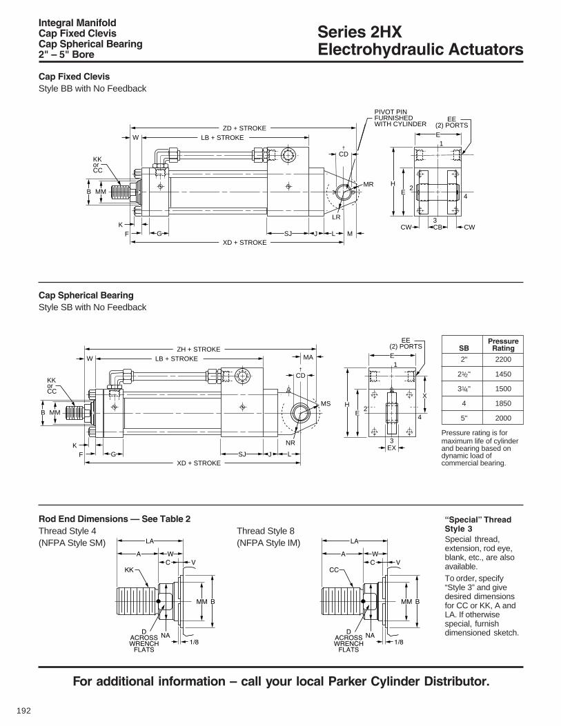
Series 2HXElectrohydraulic Actuators
For additional information – call your local Parker Cylinder Distributor.
192
Rod End Dimensions — See Table 2Thread Style 4 Thread Style 8(NFPA Style SM) (NFPA Style IM)
Integral ManifoldCap Fixed ClevisCap Spherical Bearing2" – 5" Bore
Cap Fixed ClevisStyle BB with No Feedback
“Special” ThreadStyle 3Special thread,extension, rod eye,blank, etc., are alsoavailable.To order, specify“Style 3” and givedesired dimensionsfor CC or KK, A andLA. If otherwisespecial, furnishdimensioned sketch.
Cap Spherical BearingStyle SB with No Feedback
2" 2200
21/2" 1450
31/4" 1500
4 1850
5" 2000
Pressure rating is formaximum life of cylinderand bearing based ondynamic load ofcommercial bearing.
PressureSB Rating
K
W
PIVOT PINFURNISHEDWITH CYLINDER
F
MMB
KKorCC
G SJ L
E
EH
EE(2) PORTS
1
4
3
2
M
MR
LR
JXD + STROKE
ZD + STROKELB + STROKE
CBCW CW
†CD
K
W MA
F
MMB
KKorCC
G SJ L
E
E
XH
EE(2) PORTS
1
4
3
2MS
NR
JXD + STROKE
ZH + STROKELB + STROKE
EX
†CD

Series 2HXElectrohydraulic Actuators
For Cylinder Division Plant Locations – See Page II.
193
B
127/8
131/4
13
14
143/8
141/4
16
163/8
161/8
173/8
175/8
175/8
175/8
Table 2 — Rod End and Envelope Dimensions
NA
43/8
43/8
43/8
43/8
LBAdd Stroke
NA
3.04
3.54
3.125
3.625
Rod +.000Rod Dia. -.002
Bore No. MM CC KK A B C D LA NA V W15/16
111/16
15/16
15/16
115/16
111/16
111/16
23/8
115/16
115/16
33/8
23/8
27/8
3/81/23/81/43/83/81/43/81/41/43/83/83/8
2
2
3
1
2
3
1
2
3
1
2
3
4
15/8
2
15/8
15/8
21/4
2
2
3
21/4
21/4
31/2
3
31/2
11/4-12
11/2-12
11/4-12
11/4-12
13/4-12
11/2-12
11/2-12
21/4-12
13/4-12
13/4-12
31/4-12
21/4-12
23/4-12
117/8
121/14
12
123/4
131/8
13
141/8
141/2
141/4
147/8
151/8
151/8
151/8
Thread
13/8
13/4
13/8
13/8
2
13/4
13/4
21/2
2
2
31/2
21/2
3
1.999
2.374
1.999
1.999
2.624
2.374
2.374
3.124
2.624
2.624
4.249
3.124
3.749
5/83/45/85/87/83/43/4
17/87/8
1
1
1
11/8
11/2
11/8
11/8
111/16
11/2
11/2
21/16
111/16
111/16
3
21/16
25/8
1-14
11/4-12
1-14
1-14
11/2-12
11/4-12
11/4-12
17/8-12
11/2-12
11/2-12
21/2-12
17/8-12
21/4-12
25/8
31/4
25/8
21/2
31/2
31/8
3
43/8
33/8
33/8
47/8
43/8
47/8
1
11/4
17/8
11/4
11/8
1
13/8
11/8
11/8
13/8
13/8
13/8
103/8
103/4
101/2
111/4
115/8
111/2
141/8
141/2
141/4
147/8
151/8
151/8
151/8
111/8
111/2
111/4
121/4
125/8
121/2
151/2
157/8
155/8
165/8
167/8
167/8
167/8
125/8
13
123/4
133/4
141/8
14
151/2
157/8
155/8
165/8
167/8
167/8
167/8
113/8
113/4
111/2
121/2
127/8
123/4
16
163/8
161/8
173/8
175/8
175/8
175/8
2
21/2
31/4
4
5
Add Stroke
**
Integral ManifoldCap Fixed ClevisCap Spherical Bearing2" – 5" Bore
Bore
2
21/2
31/4
4
5
Table 1 — Envelope and Mounting Dimensions
MR15/16
15/16
13/16
15/8
21/8
CB
11/4
11/4
11/2
2
21/2
CW5/8
5/8
3/4
1
11/4
CD†
.751
.751
1.001
1.376
1.751
EX21/32
21/32
7/8
13/16
117/32
MA
1
1
11/4
17/8
21/2
MS
13/8
13/8
111/16
27/16
27/8
NR
1
1
11/4
15/8
21/16
65/8
63/4
73/8
91/4
93/4
81/8
81/4
87/8
91/4
93/4
27/8
27/8
27/8
43/8
43/8
**E
3
31/2
41/2
5
61/2
10
10
12
12
12
NA
12
12
12
12
F5/8
5/8
3/4
7/8
7/8
G
13/4
13/4
2
2
2
47/8
53/8
65/8
71/8
85/8
NA
55/8
65/8
71/8
85/8
J
11/2
11/2
11/2
13/4
13/4
K7/16
7/16
9/16
9/16
13/16
L
11/4
11/4
11/2
21/8
21/4
M3/4
3/4
1
13/8
13/4
17/8
21/4
23/4
31/8
35/8
** * LR
1
15/16
11/4
13/4
21/16
+.000-.002
†Dimension CD is pin diameter.*For lower flow valves — see Standard Integral Valve Patterns in this 2HX Section, Group A, G.** For higher flow valves — see Standard Integral Valve Patterns in this 2HX Section, Group D, H.
SAE EE
*
H
** *
X
** *
SJ
***
XD* **
ZD
* **
ZH*
*For lower flow valves — see Standard Integral Valve Patterns in this 2HX Section, Group A, G.** For higher flow valves — see Standard Integral Valve Patterns in this 2HX Section, Group D, H.

Series 2HXElectrohydraulic Actuators
For additional information – call your local Parker Cylinder Distributor.
194
Rod End Dimensions — See Table 2Thread Style 4 Thread Style 8(NFPA Style SM) (NFPA Style IM)
Cap Fixed ClevisStyle BB with LDT and LRT Feedback
“Special” ThreadStyle 3Special thread,extension, rod eye,blank, etc., are alsoavailable.To order, specify“Style 3” and givedesired dimensionsfor CC or KK, A andLA. If otherwisespecial, furnishdimensioned sketch.
Cap Spherical BearingStyle SB with LDT and LRT Feedback
2" 2200
21/2" 1350
31/4" 1350
4" 1400
5" 1800
Pressure rating is formaximum life of cylinderand bearing based ondynamic load ofcommercial bearing.
PressureSB Rating
K
W
†CD
PIVOT PINFURNISHEDWITH CYLINDER
F
MMB
KKorCC
G SJ L
E
EH
X
EE(2) PORTS
1
4
3
2
M
MR
LR
JXK + STROKE
ZK + STROKELB + STROKE
CBCW CW
LJ
K
W MA
F
MMB
KKorCC
G SJ L
E
E
XH
EE(2) PORTS
1
4
3
2MS
NR
JXK + STROKE
ZM + STROKELB + STROKE
EX
LJ
†CD
Integral ManifoldCap Fixed ClevisCap Spherical Bearing2" – 5" Bore

Series 2HXElectrohydraulic Actuators
For Cylinder Division Plant Locations – See Page II.
195
B
*** LJ††
51/2
51/2
51/2
53/4
53/4
NA
3.04
3.54
3.125
3.625
SAE EE
Add StrokeRod +.000
Rod Dia. -.002Bore No. MM CC KK A B C D LA NA V W
15/16
111/16
15/16
15/16
115/16
111/16
111/16
23/8
115/16
115/16
33/8
23/8
27/8
3/81/23/81/43/83/81/43/81/41/43/83/83/8
2
2
3
1
2
3
1
2
3
1
2
3
4
15/8
2
15/8
15/8
21/4
2
2
3
21/4
21/4
31/2
3
31/2
11/4-12
11/2-12
11/4-12
11/4-12
13/4-12
11/2-12
11/2-12
21/4-12
13/4-12
13/4-12
31/4-12
21/4-12
23/4-12
157/8
161/14
16
163/4
171/8
17
181/8
181/2
181/4
187/8
191/8
191/8
191/8
Thread
13/8
13/4
13/8
13/8
2
13/4
13/4
21/2
2
2
31/2
21/2
3
1.999
2.374
1.999
1.999
2.624
2.374
2.374
3.124
2.624
2.624
4.249
3.124
3.749
5/83/45/85/87/83/43/4
17/87/8
1
1
1
11/8
11/2
11/8
11/8
111/16
11/2
11/2
21/16
111/16
111/16
3
21/16
25/8
1-14
11/4-12
1-14
1-14
11/2-12
11/4-12
11/4-12
17/8-12
11/2-12
11/2-12
21/2-12
17/8-12
21/4-12
25/8
31/4
25/8
21/2
31/2
31/8
3
43/8
33/8
33/8
47/8
43/8
47/8
1
11/4
17/8
11/4
11/8
1
13/8
11/8
11/8
13/8
13/8
13/8
143/8
143/4
141/2
151/4
155/8
151/2
181/8
181/2
181/4
187/8
191/8
191/8
191/8
151/8
151/2
151/4
161/4
165/8
161/2
191/2
197/8
195/8
205/8
207/8
207/8
207/8
165/8
17
163/4
173/4
181/8
18
191/2
197/8
195/8
205/8
207/8
207/8
207/8
153/8
153/4
151/2
161/2
167/8
163/4
20
203/8
201/8
213/8
215/8
215/8
215/8
167/8
171/4
17
18
183/8
181/4
20
203/8
201/8
213/8
215/8
215/8
215/8
2
21/2
31/4
4
5
Note: Electrical port or connector will be provided at position 1 of rear cap.Mounting styles BB, B, SB with analog LDT feedback require the use of Analog Output Module (AOM).*For lower flow valves — see Standard Integral Valve Patterns in this 2HX Section, Group A, G.** For higher flow valves — see Standard Integral Valve Patterns in this 2HX Section, Group D, H.
Table 2 — Rod End and Envelope Dimensions
Bore
2
21/2
31/4
4
5
Table 1 — Envelope and Mounting Dimensions
NA
12
12
12
12
†Dimension CD is pin diameter.*For lower flow valves — see Standard Integral Valve Patterns in this 2HX Section, Group A, G.** For higher flow valves — see Standard Integral Valve Patterns in this 2HX Section, Group D, H.††“RO” style integral cable only on LDT.For RB style connection on LDT consult factory for LJ, ZK, XK dimensions.Velocity of LRT actuators must not exceed 30 ips.
E
3
31/2
41/2
5
61/2
10
10
12
12
12
F5/8
5/8
3/4
7/8
7/8
G
13/4
13/4
2
2
2
MR15/16
15/16
13/16
15/8
21/8
CB
11/4
11/4
11/2
2
21/2
CW5/8
5/8
3/4
1
11/4
CD†
.751
.751
1.001
1.376
1.751
EX21/32
21/32
7/8
13/16
117/32
MA
1
1
11/4
17/8
21/2
MS
13/8
13/8
111/16
27/16
27/8
NR
1
1
11/4
15/8
21/16
65/8
63/4
73/8
91/4
93/4
NA
81/4
87/8
91/4
93/4
27/8
27/8
27/8
43/8
43/8
NA
43/8
43/8
43/8
43/8
* **
47/8
53/8
65/8
71/8
85/8
NA
55/8
65/8
71/8
85/8
J
11/2
11/2
11/2
13/4
13/4
K7/16
7/16
9/16
9/16
13/16
L
11/4
11/4
11/2
21/8
21/4
M3/4
3/4
1
13/8
13/4
17/8
21/4
23/4
31/8
35/8
LR
1
15/16
11/4
13/4
21/16
+.000-.002
LBAdd Stroke
***
Integral ManifoldCap Fixed ClevisCap Spherical Bearing2" – 5" Bore
*
H
**
X
**
**
XK
* **
ZK
* **
ZM
*
*
SJ

Series 2HXElectrohydraulic Actuators
For additional information – call your local Parker Cylinder Distributor.
196
Rod End Dimensions — See Table 2Thread Style 4 Thread Style 8(NFPA Style SM) (NFPA Style IM)
Head Square FlangeStyle JB — All Feedback Types
“Special” ThreadStyle 3Special thread,extension, rod eye,blank, etc., are alsoavailable.To order, specify“Style 3” and givedesired dimensionsfor CC or KK, A andLA. If otherwisespecial, furnishdimensioned sketch.
Intergral ManifoldHead Square FlangeHead Rectangular FlangeHead Rectangular, 2" – 5" Bore
Head Rectangular FlangeStyle J — All Feedback Types
Head RectangularStyle JJ — All Feedback Types
Tie rod nuts counterbored cap end.
Tie rod nuts counterbored cap end.
Tie rod nuts counterbored cap end.
*Maximum pressure rating — push application.
2500
2500
2500
2500
2500
2200
1500
1500
1500
1500
1500
750
BoreSize 5
—
—
—
—
—
—
4—
—
—
—
—
1200
3—
—
1900
2100
1800
1650
21
Rod Code
Max. PSI — Push*
11/2
2
21/2
31/4
4
5
WF
RT
BRD
KKorCC
GSJ
E
E
X
HR
EE(2) PORTS1
4
3
2
ZJ + STROKELG + STROKE
FB8 HOLESTF
UF LAF
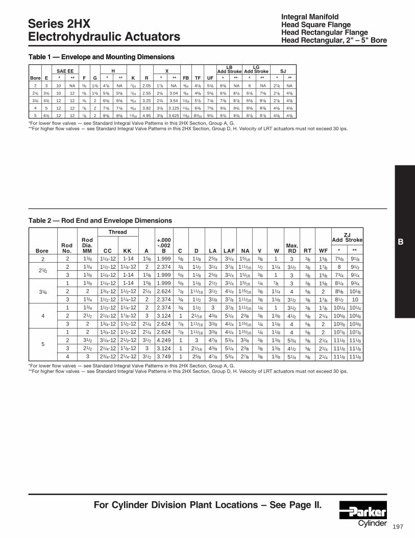
Series 2HXElectrohydraulic Actuators
For Cylinder Division Plant Locations – See Page II.
197
B
6
61/8
65/8
83/8
87/8
* ** * *
10
10
12
12
12
*
65/8
63/4
73/8
91/4
93/4
NA
81/4
87/8
91/4
93/4
* **
LBAdd Stroke
27/8
27/8
27/8
43/8
43/8
NA
43/8
43/8
43/8
43/8
* **
Integral ManifoldHead Square FlangeHead Rectangular FlangeHead Rectangular, 2" – 5" Bore
Rod +.000Rod Dia. -.002
Bore No. MM CC KK A B C D LA LAF NA V W2
2
3
1
2
3
1
2
3
1
2
3
4
15/8
2
15/8
15/8
21/4
2
2
3
21/4
21/4
31/2
3
31/2
11/4-12
11/2-12
11/4-12
11/4-12
13/4-12
11/2-12
11/2-12
21/4-12
13/4-12
13/4-12
31/4-12
21/4-12
23/4-12
Thread
13/8
13/4
13/8
13/8
2
13/4
13/4
21/2
2
2
31/2
21/2
3
1.999
2.374
1.999
1.999
2.624
2.374
2.374
3.124
2.624
2.624
4.249
3.124
3.749
5/83/45/85/87/83/43/4
17/87/8
1
1
1
11/8
11/2
11/8
11/8
111/16
11/2
11/2
21/16
111/16
111/16
3
21/16
25/8
1-14
11/4-12
1-14
1-14
11/2-12
11/4-12
11/4-12
17/8-12
11/2-12
11/2-12
21/2-12
17/8-12
21/4-12
25/8
31/4
25/8
21/2
31/2
31/8
3
43/8
33/8
33/8
47/8
43/8
47/8
2
21/2
31/4
4
5
Table 2 — Rod End and Envelope Dimensions
Table 1 — Envelope and Mounting Dimensions
Bore
2
21/2
31/4
4
5
Table 1 — Envelope and Mounting Dimensions
NA
12
12
12
12
*For lower flow valves — see Standard Integral Valve Patterns in this 2HX Section, Group A, G.**For higher flow valves — see Standard Integral Valve Patterns in this 2HX Section, Group D, H. Velocity of LRT actuators must not exceed 30 ips.
E
3
31/2
41/2
5
61/2
SAE EEF5/8
5/8
3/4
7/8
7/8
G
13/4
13/4
2
2
2
47/8
53/8
65/8
71/8
85/8
NA
55/8
65/8
71/8
85/8
UF
51/8
55/8
71/8
75/8
93/4
K7/16
7/16
9/16
9/16
13/16
R
2.05
2.55
3.25
3.82
4.95
17/8
21/4
23/4
31/8
35/8
NA
3.04
3.54
3.125
3.625
FB9/16
9/16
11/16
11/16
15/16
TF
41/8
45/8
57/8
63/8
83/16
15/16
111/16
15/16
15/16
115/16
111/16
111/16
23/8
115/16
115/16
33/8
23/8
27/8
3/81/23/81/43/83/81/43/81/41/43/83/83/8
3/83/83/83/85/83/83/85/85/85/85/85/85/8
1
11/4
17/8
11/4
11/8
1
13/8
11/8
11/8
13/8
13/8
13/8
3
31/2
3
3
4
31/2
31/2
41/2
4
4
53/4
41/2
51/4
RTMax.RD
31/4
37/8
31/4
31/4
41/4
37/8
37/8
51/4
41/4
41/4
53/4
51/4
53/4
91/8
91/2
91/4
93/4
101/8
10
101/4
105/8
103/8
107/8
111/8
111/8
111/8
75/8
8
73/4
81/4
85/8
81/2
101/4
105/8
103/8
107/8
111/8
111/8
111/8
* **
ZJAdd Stroke
15/8
17/8
15/8
15/8
2
17/8
17/8
21/4
2
2
21/4
21/4
21/4
WF
**
H
**
X
**NA
75/8
81/8
83/8
87/8
LGAdd Stroke SJ
*For lower flow valves — see Standard Integral Valve Patterns in this 2HX Section, Group A, G.**For higher flow valves — see Standard Integral Valve Patterns in this 2HX Section, Group D, H. Velocity of LRT actuators must not exceed 30 ips.

Series 2HXElectrohydraulic Actuators
For additional information – call your local Parker Cylinder Distributor.
198
Rod End Dimensions — See Table 2Thread Style 4 Thread Style 8(NFPA Style SM) (NFPA Style IM)
Integral ManifoldHead TrunnionIntermediate Trunnion2" – 5" Bore
“Special” ThreadStyle 3Special thread,extension, rod eye,blank, etc., are alsoavailable.To order, specify“Style 3” and givedesired dimensionsfor CC or KK, A andLA. If otherwisespecial, furnishdimensioned sketch.
Intermediate TrunnionStyle DD — All Feedback Types
!"
Head TrunnionStyle D — All Feedback Types

Series 2HXElectrohydraulic Actuators
For Cylinder Division Plant Locations – See Page II.
199
B
91/8
91/2
91/4
93/4
101/8
10
101/4
105/8
103/8
107/8
111/8
111/8
111/8
*
NA
12
12
12
12
Integral ManifoldHead TrunnionIntermediate Trunnion2" – 5" Bore
75/8
8
73/4
81/4
85/8
81/2
101/4
105/8
103/8
97/8
111/8
111/8
111/8
65/8
63/4
73/8
91/4
93/4
NA
81/4
87/8
91/4
93/4
LBAdd Stroke
TD
1.375
1.375
1.750
1.750
1.750
NA
3.04
3.54
3.125
3.625
Rod +.000Rod Dia. -.002
Bore No. MM CC KK A B C D LA NA V W15/16
111/16
15/16
15/16
115/16
111/16
111/16
23/8
115/16
115/16
33/8
23/8
27/8
3/81/23/81/43/83/81/43/81/41/43/83/83/8
2
2
3
1
2
3
1
2
3
1
2
3
4
15/8
2
15/8
15/8
21/4
2
2
3
21/4
21/4
31/2
3
31/2
11/4-12
11/2-12
11/4-12
11/4-12
13/4-12
11/2-12
11/2-12
21/4-12
13/4-12
13/4-12
31/4-12
21/4-12
23/4-12
43/16
47/16
43/16
411/16
51/16
415/16
415/16
55/16
51/16
51/16
55/16
55/16
55/16
Thread
13/8
13/4
13/8
13/8
2
13/4
13/4
21/2
2
2
31/2
21/2
3
1.999
2.374
1.999
1.999
2.624
2.374
2.374
3.124
2.624
2.624
4.249
3.124
3.749
5/83/45/85/87/83/43/4
17/87/8
1
1
1
11/8
11/2
11/8
11/8
111/16
11/2
11/2
21/16
111/16
111/16
3
21/16
25/8
1-14
11/4-12
1-14
1-14
11/2-12
11/4-12
11/4-12
17/8-12
11/2-12
11/2-12
21/2-12
17/8-12
21/4-12
25/8
31/4
25/8
21/2
31/2
31/8
3
43/8
33/8
33/8
47/8
43/8
47/8
1
11/4
17/8
11/4
11/8
1
13/8
11/8
11/8
13/8
13/8
13/8
21/2
23/4
21/2
25/8
3
27/8
27/8
31/4
3
3
31/4
31/4
31/4
2
21/2
31/4
4
5
†Dimension XI to be specified by customer.*For lower flow valves — see Standard Integral Valve Patterns in this 2HX Section, Group A, G.** For higher flow valves — see Standard Integral Valve Patterns in this 2HX Section, Group D, H.
Table 2 — Rod End and Envelope Dimensions
Bore
2
21/2
31/4
4
5
UW
41/8
45/8
513/16
63/8
73/4
UM
61/4
63/4
81/2
9
101/2
UT
53/4
61/4
8
81/2
10
K7/16
7/16
9/16
9/16
13/16
TM
31/2
4
5
51/2
7
*For lower flow valves — see Standard Integral Valve Patterns in this 2HX Section, Group A, G.** For higher flow valves — see Standard Integral Valve Patterns in this 2HX Section, Group D, H. Velocity of LRT actuators must not exceed 30 ips.
E
3
31/2
41/2
5
61/2
10
10
12
12
12
F5/8
5/8
3/4
5/8
7/8
G
13/4
13/4
2
2
2
47/8
53/8
65/8
71/8
85/8
NA
55/8
65/8
71/8
85/8
BD
11/2
11/2
2
2
2
17/8
21/4
23/4
31/8
35/8
+.000-.001
TL
13/8
13/8
13/4
13/4
13/4
27/8
27/8
27/8
43/8
43/8
NA
43/8
43/8
43/8
43/8
Table 1 — Envelope and Mounting Dimensions
Min.XI†XG
ZJAdd Stroke
SAE EE
* **
H
**
X
* **
SJ
* *** **
* **

Series 2HXElectrohydraulic Actuators
For additional information – call your local Parker Cylinder Distributor.
200
Rod End Dimensions — See Table 2Thread Style 4 Thread Style 8(NFPA Style SM) (NFPA Style IM)
Integral MountNo MountTie Rods Extended Head End2" – 5" Bore
No MountStyle T — All Feedback Types
“Special” ThreadStyle 3Special thread,extension, rod eye,blank, etc., are alsoavailable.To order, specify“Style 3” and givedesired dimensionsfor CC or KK, A andLA. If otherwisespecial, furnishdimensioned sketch.
Tie Rods Extended Head EndStyle TB — All Feedback Types

Series 2HXElectrohydraulic Actuators
For Cylinder Division Plant Locations – See Page II.
201
B
**
NA
43/8
43/8
43/8
43/8
NA
12
12
12
12
E
3
31/2
41/2
5
61/2
10
10
12
12
12
F5/8
5/8
3/4
7/8
7/8
G
13/4
13/4
2
2
2
47/8
53/8
65/8
71/8
85/8
NA
55/8
65/8
71/8
85/8
K7/16
7/16
9/16
9/16
13/16
R
2.05
2.55
3.25
3.82
4.95
17/8
21/4
23/4
31/8
35/8
NA
3.04
3.54
3.125
3.625
Rod +.000Rod Dia. -.002
Bore No. MM CC KK A B C D LA NA V W2
2
3
1
2
3
1
2
3
1
2
3
4
15/8
2
15/8
15/8
21/4
2
2
3
21/4
21/4
31/2
3
31/2
11/4-12
11/2-12
11/4-12
11/4-12
13/4-12
11/2-12
11/2-12
21/4-12
13/4-12
13/4-12
31/4-12
21/4-12
23/4-12
Thread
13/8
13/4
13/8
13/8
2
13/4
13/4
21/2
2
2
31/2
21/2
3
1.999
2.374
1.999
1.999
2.624
2.374
2.374
3.124
2.624
2.624
4.249
3.124
3.749
5/83/45/85/87/83/43/4
17/87/8
1
1
1
11/8
11/2
11/8
11/8
111/16
11/2
11/2
21/16
111/16
111/16
3
21/16
25/8
1-14
11/4-12
1-14
1-14
11/2-12
11/4-12
11/4-12
17/8-12
11/2-12
11/2-12
21/2-12
17/8-12
21/4-12
25/8
31/4
25/8
21/2
31/2
31/8
3
43/8
33/8
33/8
47/8
43/8
47/8
2
21/2
31/4
4
5
Table 2 — Rod End and Envelope Dimensions
Table 1 — Envelope and Mounting Dimensions
Bore
2
21/2
31/4
4
5
Table 1 — Envelope and Mounting Dimensions
*For lower flow valves — see Standard Integral Valve Patterns in this 2HX Section, Group A, G.**For higher flow valves — see Standard Integral Valve Patterns in this 2HX Section, Group D, H. Velocity of LRT actuators must not exceed 30 ips.
DD1/2-20
1/2-20
5/8-18
5/8-18
7/8-14
AA
2.90
3.60
4.60
5.40
7.00
BB
113/16
113/16
25/16
25/16
33/16
NA
81/4
87/8
91/4
93/4
65/8
63/4
73/8
91/4
93/4
LBAdd Stroke
27/8
27/8
27/8
43/8
43/8
15/16
111/16
15/16
15/16
115/16
111/16
111/16
23/8
115/16
115/16
33/8
23/8
27/8
3/81/23/81/43/83/81/43/81/41/43/83/83/8
1
11/4
17/8
11/4
11/8
1
13/8
11/8
11/8
13/8
13/8
13/8
91/8
91/2
91/4
93/4
101/8
10
101/4
105/8
103/8
107/8
111/8
111/8
111/8
75/8
8
73/4
81/4
85/8
81/2
101/4
105/8
103/8
97/8
111/8
111/8
111/8
ZJAdd Stroke
Integral ManifoldNo MountTie Rods Extended Head End2" – 5" Bore
**
SAE EE
* **
H
* **
X
* ***
SJ
*
***
*For lower flow valves — see Standard Integral Valve Patterns in this 2HX Section, Group A, G.**For higher flow valves — see Standard Integral Valve Patterns in this 2HX Section, Group D, H.

Series 2HXElectrohydraulic Actuators
For additional information – call your local Parker Cylinder Distributor.
202
Rod End Dimensions — See Table 2Thread Style 4 Thread Style 8(NFPA Style SM) (NFPA Style IM)
Integral ManifoldSide TappedSide Lugs2" – 5" Bore
Side TappedStyle F — All Feedback Types
“Special” ThreadStyle 3Special thread,extension, rod eye,blank, etc., are alsoavailable.To order, specify“Style 3” and givedesired dimensionsfor CC or KK, A andLA. If otherwisespecial, furnishdimensioned sketch.
Side LugsStyle C — All Feedback Types
!"##$"##
!

Series 2HXElectrohydraulic Actuators
For Cylinder Division Plant Locations – See Page II.
203
BRod Style Style +.000Rod Dia. 8 4 & 9 -.002
Bore No. MM CC KK A B C D LA NA V W ND
27/8
27/8
27/8
43/8
43/8
NA
43/8
43/8
43/8
43/8
***
SJ
NA
3.04
3.54
3.125
3.625
NA
55/8
65/8
71/8
85/8
65/8
63/4
73/8
91/4
93/4
NA
81/4
87/8
91/4
93/4
LBAdd Stroke
NT1/2-13
5/8-11
3/4-10
1-8
1-8
SB†
9/16
13/16
13/16
11/16
11/16
Integral ManifoldSide TappedSide Lugs2" – 5" Bore
Bore
2
21/2
31/4
4
5
Table 1 — Envelope and Mounting Dimensions
SU
11/4
19/16
19/16
2
2
SW1/2
11/16
11/16
7/8
7/8
TN15/16
15/16
11/2
21/16
215/16
TS
4
47/8
57/8
63/4
81/4
US
5
61/4
71/4
81/2
10
E
3
31/2
41/2
5
61/2
10
10
12
12
12
NA
12
12
12
12
F5/8
5/8
3/4
7/8
7/8
G
13/4
13/4
2
2
2
47/8
53/8
65/8
71/8
85/8
J
11/2
11/2
11/2
13/4
13/4
K7/16
7/16
9/16
9/16
13/16
* ST3/4
1
1
11/4
11/4
*For lower flow valves — see Standard Integral Valve Patterns in this 2HX Section, Group A, G. **For higher flow valves — see Standard Integral Valve Patterns in this 2HX Section, Group D, H. Velocity of LRT actuators must not exceed 30 ips. † Upper surface spot faced for socket head screws.
15/16
111/16
15/16
15/16
115/16
111/16
111/16
23/8
115/16
115/16
33/8
23/8
27/8
3/81/23/81/43/83/81/43/81/41/43/83/83/8
2
2
3
1
2
3
1
2
3
1
2
3
4
15/8
2
15/8
15/8
21/4
2
2
3
21/4
21/4
31/2
3
31/2
11/4-12
11/2-12
11/4-12
11/4-12
13/4-12
11/2-12
11/2-12
21/4-12
13/4-12
13/4-12
31/4-12
21/4-12
23/4-12
21/8
29/16
25/16
25/16
211/16
29/16
23/4
31/8
27/8
27/8
31/8
31/8
31/8
Thread
13/8
13/4
13/8
13/8
2
13/4
13/4
21/2
2
2
31/2
21/2
3
1.999
2.374
1.999
1.999
2.624
2.374
2.374
3.124
2.624
2.624
4.249
3.124
3.749
5/83/45/85/87/83/43/4
17/87/8
1
1
1
11/8
11/2
11/8
11/8
111/16
11/2
11/2
21/16
111/16
111/16
3
21/16
25/8
1-14
11/4-12
1-14
1-14
11/2-12
11/4-12
11/4-12
17/8-12
11/2-12
11/2-12
21/2-12
17/8-12
21/4-12
25/8
31/4
25/8
21/2
31/2
31/8
3
43/8
33/8
33/8
47/8
43/8
47/8
1
11/4
17/8
11/4
11/8
1
13/8
11/8
11/8
13/8
13/8
13/8
7/16
1/21/2
11/16
11/16
11/16
11/16
11/16
11/16
1
1
1
1
25/8
27/8
25/8
23/4
31/8
3
3
33/8
31/8
31/8
33/8
33/8
33/8
2
21/2
31/4
4
5
ZJAdd Stroke
Table 2 — Rod End and Envelope Dimensions
17/8
21/4
23/4
31/8
35/8
XS XT75/8
8
73/4
81/4
85/8
81/2
101/4
105/8
103/8
97/8
111/8
111/8
111/8
*
91/8
91/2
91/4
93/4
101/8
10
101/4
105/8
103/8
107/8
111/8
111/8
111/8
SAE EE
** *
H
** *
X
** * **
**
*For lower flow valves — see Standard Integral Valve Patterns in this 2HX Section, Group A, G.**For higher flow valves — see Standard Integral Valve Patterns in this 2HX Section, Group D, H.
SS35/8
33/8
41/8
4
41/2
SN27/8
3
31/2
33/4
41/4
Add Stroke

Series 2HXElectrohydraulic Actuators
For additional information – call your local Parker Cylinder Distributor.
204
LDT SpecificationsTechnical Information
TransducerLDT Technical Specifications
LDT Technical SectionThe 2HX-LDT Actuator is the most versatile actuator that weoffer. Utilizing the Temposonics LH™ feedback device, thereare three distinct outputs available to suit most applications.Velocity is limited primarily by the limits of mechanicalcomponents outside of the actuator, although position update
time can affect the system ramp-down. The 2HX-LDTActuator is the industry favorite in tough, rugged machineryapplications. A key advantage is the absolute position outputwhich is not lost if there is a power failure.
MagnetostrictionIn a LDT position sensor, a pulse is induced in a specially-designed magnetostrictive waveguide by the momentaryinteraction of two magnetic fields. One field comes from amovable magnet which passes along the outside of thesensor tube, the other field comes from a current pulse orinterrogation pulse launched along the waveguide. Theinteraction between the two magnetic fields produces a strainpulse, which travels at sonic speed along the waveguide untilthe pulse is detected at the head of the sensor. The positionof the magnet is determined with high precision by measuringthe elapsed time between the launching of the electronicinterrogation pulse and the arrival of the strain pulse. As aresult, accurate non-contact position sensing is achievedwith absolutely no wear to the sensing components.
An average of 200 ultrasonic strain pulses are launched forevery reading. With so many readings taken for each posi-tion, vibration and shock have negligible effect on thereadings. The transducer assembly is shielded to eliminateinterference caused by electromagnetic fields in the radiofrequency range. In addition, static magnetic fields of severalhundred gauss must get as close as 3/16" from the protectivetube before any interference in transducer operation occurs.
Features• High immunity to shock and vibration• Replaceable sensing element• Single voltage input +13 to 26.4Vdc• 3000 psi operating pressure• Multiple outputs from on-board electronics• Easy installation and maintenance• Standard strokes up to 100" (analog), 120" (digital)• Includes 5' extension cable with RB connector standard
If cylinder includes false stage enclosure, LDT will besupplied with RO Integral Pigtail Cable (5' length). Refer topages 194 and 195 for “LJ” and “E” dimensions.
!
"#$% $"
&' ( "
")
$
%
Feedback AccuracyThe accuracy of a given feedback device is a composite of anumber of factors, the most important of which are:Resolution – The smallest movement of the device that willproduce a measurable output.Non-Linearity – The deviation of the signal from a straight lineoutput.Repeatability – The maximum deviation of output signal forrepeated positioning to a fixed point.Hysteresis – The deviation of the signal when approaching afixed point from opposite directions.
Temperature Coefficient – The shift in output due to tempera-ture change. This is a combination of the effect of tempera-ture on the cylinder, the transducer and the electronics.These factors which are normally additive refer to thefeedback device itself. The performance achieved by a givensystem depends on the various factors such as systemstiffness, valve performance, friction, temperature variation,and backlash in mechanical linkages to the cylinder.In the case of front flange mounted cylinders, the stretch ofthe cylinder due to hydraulic pressure changes may affectposition repeatability and system performance.

Series 2HXElectrohydraulic Actuators
For Cylinder Division Plant Locations – See Page II.
205
B
AOM Output SpecificationsDisplacement Outputs:
Voltage0 to 10V DC — forward and reverse acting (forward standard)0 to -10V DC — forward and reverse acting-10 to +10V DC — forward and reverse acting0 to +5V DC — forward and reverse acting-5 to +5V DC — forward and reverse actingCurrent4 to 20 mA grounded (forward and reverse)4 to 20 mA ungrounded (forward and reverse)
Velocity Outputs:# inches/second = ±10V DC(1 to 400 in/sec)
Power Supply:+24V DC standard±15V DC optional
LDT SpecificationsOutput OptionsAnalog Output Module
LDT Output OptionsThe LDT utilizes on-board electronics contained in the sensorhead to generate several absolute output options. Therequired output must be specified at the time of order. Inapplications where it is desirable to locate the output elec-tronics in a remote location, or where the sensor head is notaccessible, an optional Analog Output Module (AOM) is avail-able. The standard outputs for each option are listed below.
Standard LDT Outputs
• Analog Position (absolute)0 to +10V DC or +10 to 0V DC4 to 20mA or 20 to 4mA (grounded)0 to 20mA or 20 to 0mA (grounded)
• Digital Position (absolute)Differential Start/StopPWM Pulse Duration
• Neuter (For use with AOM)Single Pulse Square Wave
Note: Velocity output or velocity and position output requiresuse of an AOM.
Analog Output Module: AOM OptionThe Analog Output Module provides an absolute analogdisplacement or optional velocity output signal. It containsthe electronics to send the interrogation pulse to the LDT andreceive the return pulse from the LDT. The AOM is mountedseparately from the LDT and comes standard with strainrelief connectors. Optional MS connectors are available.
Note: An LDT with Neuter output is required for use with anAOM. AOM is recommended to allow adjustment for capmounting styles B, BB and SB.
Optional metal MS connectors are only available for connec-tion to the AOM. The connection at the probe requires anMS-style connector. For applications requiring true MSconnectors at the probe, consult factory.
Standard SpecificationsParameter SpecificationResolution: Analog: Infinite
Digital:1 ÷ [gradient x crystal freq. (mHz) x circulation]
Non-Linearity: ±0.02% or ±0.05 mm (±0.002 in.), whichever is greater0.002 in. is the minimum absolute linearity and varies with sensor model
Repeatability: Equal to resolution
Hysteresis: <0.02 mm (0.0008 in.)
Outputs: Analog: Voltage or CurrentDigital: Start/Stop or PWM
Measuring Range: Analog: 25 to 2540 mm (1 to 100 in.)Digital: 25 to 7600 mm (1 to 300 in.)
Operating Voltage: +13.5 to 26.4 Vdc (±0%): Strokes <1525 mm (60 in.)+24 Vdc (±10%): Strokes > 1525 mm (60 in.)
Power Consumption:100 mA
Operating Head Electronics: -40 to 85°C (-40 to 185°F)Temperature: Sensing Element: -40 to 105°C (-40 to 221°F)
EMC Test*: DIN EN 50081-1 (Emissions);DIN EN 50082-2 (Immunity)
Shock Rating: 100 g (single hit)/IEC standard 68-2-27 (survivability)
Vibration Rating: 5 g/10-150 Hz/IEC standard 68-2-6
Adjustability: Field adjustable zero and span to 5%(for active sensors only) of active stroke
Update Time: Analog: <1 msDigital: Minimum = [Stroke (specified in inches) + 3] x 9.1 µs
Operating Pressure: 5000 psi static;10,000 psi spike
Housing Style/ Aluminum die-cast head,Enclosure: IP 67 stainless steel rod & flange
(LH flange: M18 x 1.5 or 3/4-16 UNF-3A)
*EMC test specification does not include sensors with the RB connection style.
The above specifications for analog sensors are assuming that output ripple is averaged by themeasuring device as with any typical analog device. Specifications are subject to change withoutnotice. Consult the factory for specifications critical to your needs.
Note: LDT comes standard with an RB style connector and 5' extension cable. If cylinder includesstyle A protective enclosure, LDT will be supplied with RO Integral Pigtail Cable (5' length).
Note: Velocity output or velocity and position output requires use of an AOM.

Series 2HXElectrohydraulic Actuators
For additional information – call your local Parker Cylinder Distributor.
206
LDT SpecificationsConnector OptionsWiring Information
LDT Connector OptionsThe LDT is available with three standard Connector Optionsas shown below. The style RB connector with a 5' extensioncable is standard except for BB and SB mounting styles. RO
style connector is standard for BB and SB mounting styleswith a false stage enclosure. Please specify the connectoroption at the time of order.
Style RB — Connector with Cable Style RG – Connector with Cable
Style RO — Integral Pigtail Cable Hex Dimensions
Table A — LDT Wiring with RB* Style Connector and Cable
Pulse-Duration Pulse-DurationOutput Output
(External (Internal Start/Stop Neuter Analog OutputFor Temposonics LH™ Interrogation) Interrogation) Output Output (Voltage or Current)
Wire ColorSolid Leads
Pin No. (Note 2) Function Function Function Function Function Function
1 White DC Ground DC Ground DC Ground DC Ground DC Ground DC Ground
2 Brown Frame Ground Frame Ground Frame Ground Frame Ground Frame Ground Frame Ground
3 Gray (-) Gate (-) Gate (-) Gate — 0 - 10 Vdc Return Current Return
4 Pink (+) Gate (+) Gate (+) Gate — 0 to 10 Vdc 4 to 20 mA or
0 to 20 mA or
20 to 4mA or
20 to 0 mA
(See Figure A-1)
5 Red +13.5 to 26.4 Vdc +13.5 to 26.4 Vdc +13.5 to 26.4 Vdc +13.5 to 26.4 Vdc +13.5 to 26.4 Vdc +13.5 to 26.4 Vdc
6 Blue — — — — — —
7 Black — — — Signal Return 10 to 0 Vdc —
8 Violet — — — Signal Output 10 - 0 Vdc Return —
9 Yellow (+) Interrogation (Note 4) — (+) Interrogation (+) Interrogation — —
(Note 3)
10 Green (-) Interrogation (Note 4) — (-) Interrogation (+) Interrogation — —
(Note 3)
Figure A-1 — LDT Pin Diagram
4. Important: Frame ground should always be connected. Whenusing MT, M, FT or F extension cables frame ground is the BROWNwire.* RB style connectors are supplied as standard on all LDT‘s unlessspecified otherwise.
Notes for Table A:1. Interrogation pulse: 1 to 4 microseconds maximum pulse duration.2. WARNING: For single-ended interrogation, the unusedinterrogation lead must be connected to DC ground.3. When using a Temposonics LH™ position sensor with a pulse-width-modulated output (w/external interrogation) or Start/Stopoutput, it is recommended that both the positiive and negativeinterrogations leads are connected to a differentiated driving sourceto produce a differential interrogation signal.
TOP VIEW

Series 2HXElectrohydraulic Actuators
For Cylinder Division Plant Locations – See Page II.
207
B
Pulse-Duration Pulse-DurationOutput Output
(External (Internal Start/Stop Neuter Analog OutputInterrogation) Interrogation) Output Output (Voltage or Current)
IntegralCable Function Function
Color Code Function Function Function Function (Voltage) (Current)
White DC Ground DC Ground DC Ground DC Ground DC Ground DC Ground
Drain Wire Frame Ground Frame Ground Frame Ground Frame Ground Frame Ground Frame Ground
Gray (-) Gate (-) Gate (-) Gate Signal Return 0 - 10 Vdc Return 4 to 20 mA Out
Pink (+) Gate (+) Gate (+) Gate Signal Output 0 to 10 Vdc Return
(See Figure B-1)
Red +13.5 to 26.4 Vdc +13.5 to 26.4 Vdc +13.5 to 26.4 Vdc +13.5 to 26.4 Vdc +13.5 to 26.4 Vdc +13.5 to 26.4 Vdc
Yellow (+) Interrogation — (+) Interrogation (+) Interrogation 10 to 0 Vdc(Note 3) (Note 3) (Note 2)
Green (-) Interrogation — (-) Interrogation (-) Interrogation 10 - 0 Vdc Return(Note 3) (Note 3) (Note 2)
Table B: LDT Wiring with Integral Pigtail Cable*
LDT SpecificationsWiring InformationDigital Output Signal
Notes for Table A:1. Interrogation pulse: 1 to 4 microseconds maximum pulse duration.2. Warning: For single-ended interrogation, the unused interrogation lead must be connected to DC ground.3. When replacing a Temposonics II™ position sensor with a pulse-duration output (with external interrogation) or a Start/Stop output,it is recommended that both the positive and negative interrogation leads are connected to a differentiated driving source to produce adifferential interrogation signal.4. Important: Frame ground should always be connected.
Digital Output Signal (PWM)The Digital Output Electronics mounted in the head of theLDT provides the interrogation pulse to the probe. The pulseis reflected to the Digital Output Electronics by the magnetwhich strokes along the length of the transducer.
The LDT with PWM Digital Output provides a 5 Vdc TTLcompatible pulse with modulated square wave signal whichcan be transmitted to a digital counter card, Parker PMCMotion Controller, or various other customer supplieddevices. The amount of time, in milliseconds, that theoutput is “Hi,” or near 5 volts, is directly proportional to theposition of the cylinder piston. This time can also be calledthe “width” of the square wave in milliseconds. Besidesbeing proportional to the position of the cylinder piston, thiswidth can be controlled by varying the signal sampling rate(called “recirculations”). The advantage of increasing therecirculations is in improved resolution. The sacrifice is inupdate time and maximum stroke length. Figure 1 showsthe relationship of recirculations, minimum update time,and stroke length. Figure 2 shows the relationship ofrecirculations, resolution, and stroke.
We recommend the TTL interface for most LDT applicationsrequiring digital feedback; many electronic controllers areequipped to utilize this output. BCD and natural binaryoutputs are available — consult factory.
Figure 2 —Recirculations, Resolutions and Stroke Length
Figure B-1 —LDT with Current Output
Note: Style RO Integral Pigtail Cables aresupplied as standard on LDTs used with stylesA and F protective enclosures.
Term Base = 28 Megahertz Clock
Recirculations 1 2 4 8 15Resolution(inches/pulse) 0.004 0.002 0.001 0.0005 0.00035Maximum stroke(inches) 258 127 61 28 12
Figure 1. Update time (ms) = [(4.5 + stroke) inches x 0.01086 ms] x N
! "#$$#%

Series 2HXElectrohydraulic Actuators
For additional information – call your local Parker Cylinder Distributor.
208
Parker Series 2HXwith LDT and Analog Output Module (AOM)Wiring Connections and Analog Output Module Dimen-sionsAn electrical Noise Filter and Low Ripple Output Filter arestandard.
Analog Output ModuleShown with strain relief cable connectors.Refer to Installation Bulletin 1170-TSD-2 for more detailedwiring information.
Terminal Block Connections
Terminal Block 1 — Output Signal ConnectionsTB1-A Displacement Output (+)TB1-B Displacement Output (-)TB1-C Velocity (+) (Optional)TB1-D Velocity (-) (Optional)TB1-E Reserved for OptionsTB1-F Reserved for OptionsTB1-G Reserved for OptionsNote: For the optional pin assignments refer to the label inside themodule.
Terminal Block 2 — Transducer Connections (LDT withNeuter Output)
Terminal Pre-1995 Cable Colors 1995 Cable Colors FunctionTB2-B White/Blue Stripe White DC Ground
Blue/White Stripe Brown Frame
White/Brown Stripe Black Return
Gray/White Stripe Green DC Ground
TB2-C Brown/White Stripe Violet Return PulseOutput
TB2-E White/Gray Stripe Yellow InterrogationPulse
TB2-F White/Green Stripe Red VCC (12 Vdc)
Note: Cable must be grounded at or near AOM.Note: The Transducer is supplied with a pre-wired cable.
Terminal Block 3 — Power Supply ConnectionsTB3-H +15 VdcTB3-J -15 VdcTB3-K DC Common
LDT SpecificationsAnalog Output Module
Mounting(2) Socket Hex Cap Screws#10-32 UNF-2A Thread
Max. distance from transducer - 250 ft.
Frequency ResponseAnalog SystemsThe analog output module produces a DC output signal with anAC ripple component. The group shown illustrates the followingrelationship between frequency response and AC ripple.
Note: AOMs require the use of an LDT with Neuter Output.
!
"# $
& % % !
' ( !
"# $ % ")""
* %
$
'$ + , -
Ripple Magnitude and Frequency Response
. /
It shows that the AC ripple fundamental frequency is related tostroke length. For shorter strokes, this frequency is usuallybeyond the response capability of the analog control loop. Noticethat the ripple frequency equals the frequency of the interrogationpulse.
It shows how the magnitude of the ripple is related to frequencyresponse. You can enhance response by allowing the ripple toincrease. Alternatively, you can use a low level of ripple, withreduced response, for applications where response is lesscritical, such as required for A/D converters with high resolution.Unless specified, the response will be on the 1 mV curve.

Series 2HXElectrohydraulic Actuators
For Cylinder Division Plant Locations – See Page II.
209
B
! " #!
# ! " #!
! " #!
$%
" &
Standard Features• Available in strokes to 120".• Unique, easy to apply cylinder position sensing system.• Infinite resolution, high linearity and repeatability.• Innovative, resistive element is made of conductive
plastic.• 3 pin Brad Harrison electrical connector available at any
cap position not occupied by a port or mount.
How It WorksThe Parker LRT is a uniquely designed position sensor thatuses a resistive element and wiper assembly to provide ananalog output signal of a cylinder’s position. The LRT is adual element type linear potentiometer with two independentelements mounted on either side of an anodized aluminumextrusion. The LRT operates as a voltage divider. This isdone by shorting through the extrusion with the wiperassembly. The position of the wiper changes the resistiveload proportional to its position along the cylinder stroke. TheLRT is energized by applying a voltage across the unit,typically 10 VDC. As the resistive load changes with thecylinder stroke, the output voltage changes proportionally.The output voltage at the end point of the cylinder stroke isdictated by the input voltage applied across the device. Theprobe is mounted into the cylinder cap and inserted into thegun drilled piston rod. The compactness of the design onlyadds to the envelope dimensions of cylinders with 1-3/4"rods and smaller. Envelope dimensions of cylinders withlarger rods and integral cap style cylinders are unaffected.
Standard SpecificationsNon-Linearity: Less than 0.1% of full scale up to 48"stroke. Less than 1.0% of full scale over 48" stroke.
Repeatability: .001 inch
LRT SpecificationsTechnical Information
TransducerLRT Technical Specfications
Pin Chart
Pin Number On Cable On LRT Function
1 Green White (wiper) Ouput
2 Red w/Blk Black (resistor base) V-
3 Red w/White Red (resistor tip. power) V+
12' Cable
Cable#0854430012
Input Voltage: Nominal 5-50 Vdc
Operating Temperature Range: -40°F to +160°F*
Cylinder Stroke Length: Up to 120"
Electrical Connector: Brad Harrison 3-pin micro connectorinterface at position #4 standard.
Total Resistance: 800 per inch of stroke (±20%) + endresistance.
End Resistance: 800
Maximum Velocity: 30 inches per second
Life Expectancy: Greater that 50 x 106 cycles (Based on1" stroke @ 10 ips)
Fluid Medium: Petroleum based hydraulic fluids. May not beused with water based or high water content fluids.End Voltage Loss: (V source) x (400/stroke x 800)
Power Dissipation: supply voltage squared, divided by the totalresistance.
The LRT requires a high impedance interface greater than100K ohms. A maximum of 1 microamp should be requiredfrom the LRT.The accuracy of a given feedback device is a composite ofthe following factors:Temperature Coefficient: The shift in output due to temperaturechange. This is a combination of the effect of temperature onthe cylinder, the transducer and the electronics.These factors which are normally additive refer to the feed-back device itself. The performance achieved by a givensystem depends on the various factors such as systemstiffness, valve performance, friction, temperature variation,and backlash in mechanical linkages to the cylinder.In the case of front flange mounted cylinders, the stretch ofthe cylinder due to hydraulic pressure changes may affectposition repeatability and system performance.
*A high temperature option is offered to 300°F(consult factory).

Series 2HXElectrohydraulic Actuators
For additional information – call your local Parker Cylinder Distributor.
210
Protective Enclosures for Feedback DevicesStyle A — For LDT and LRT, all bore sizes. Extra heavy-duty enclosure consisting of cylinder body tube and endcap. Consult factory for dimensions. Connector type mustbe specified.
Note: Since this design uses common tie rods, theactuator must be disassembled to service or installfeedback devices.
Technical SectionOptions
Style F — For LDT and LRTFor 4" bore and larger only.Use Style A for 21/2" and 31/4" bore.
BASIC ORINTEGRAL CAP
ANTI MOISTUREPACKET
6.50
3.50" SQUARE
Intrinsically Safe LDTAn intrinsically safe system is a system ap-proved by Factory Mutual as intrinsically safe foruse in Class l, Division I, Group A, B, C, or Dhazardous locations. The system requiresapproved safety barriers and a 6 wire LDT.Consult factory for detailed information.
Explosion Proof LDTFactory Mutual Approved
Style D — For LDT Basic and Intergral Cap. Specifyconnector type (not available on 2" bore).
3.50" SQUARE(EXCEPT 3.25"BORE CYL.)
ANTI-MOISTUREPACKET 7.25

Series 2HXElectrohydraulic Actuators
For Cylinder Division Plant Locations – See Page II.
211
B
Technical SectionGeneral DataLow Friction Gland
Gland Drain
Available for high speed applications is a gland drain fittedwith the low friction option to prevent pressure buildupbetween the seals, and must be piped back to tank indepen-dent of the return line. If an independent drain line is notpossible, alternative designs can be supplied.
Seal Friction
Seal friction under a given set of working conditions is noteasily calculated due the multiplicity of variables involved.The following graph is offered as a guide for use in perfor-mance calculations, but for critical applications measure-ments should be made under simulated or actual workingconditions.
Calculation of Running FrictionThe seal friction attributable to the cylinder is calculated asthe sum of the friction due to the individual sealing elements= (wiper seal friction + rod seal friction + piston seal friction),using the following formulae:
Seal Option: Formula:Lipseal Rod + Piston 12d + 12FLd + 24FLDLipseal Rod w/ Low Friction Piston 12d + 12FLd + 12FpDLow Friction Rod + Piston 12d + 30Fpd + 6FpD Where: d = rod dia. (in.) D = bore dia. (in.)FL
= friction factor for lipseals (FL)
Fp = friction factor for PTFE (Fp)
Breakaway FrictionBreakaway friction may be calculated by applying thefollowing correction factors:
Correction factors:Lipseals: FL x 1.5Low Friction: Fp x 1.0
Sample Calculation
2HX cylinder with 3.25 dia. bore + 1.75 dia. piston rod withlow friction seals at 1500 psi.
Running Friction Calculation
Friction (lbs. force) ≅ 12d + 30Fpd + 6FpDFriction (lbs. force) ≅ 12 (1.75) + 30 (1.3 x 1.75) + 6 (1.3 x 3.25)Friction (lbs. force) ≅ 115Breakaway Friction Calculation
Fp x 1.0 ≅ Fp
Based on zero pressure:Friction (lbs. force) ≅ 12d + 30Fpd + 6FpDFriction (lbs. force) ≅ 12 (1.75) + 30 (1.3 x 1.75) + 6 (1.3 x 3.25)Friction (lbs. force) ≅ 43
Low Friction Gland
Below is a cross-sectional representation of a Parker Series2HX low friction gland. The dual step seals are of a bronze-filled PTFE material. The expanders are a square crosssection elastomer.
Operating Temperature Danger
The piston to piston-rod threaded connection is secured withan anaerobic adhesive which is temperature sensitive.Operation of the cylinder outside of the following guidelinescan cause the piston rod to unthread itself from the piston.Cylinders ordered with standard seals are assembled withanaerobic adhesive with a maximum temperature rating of+165°F. Cylinders ordered with Fluorocarbon seals areassembled with an anaerobic adhesive with a maximumtemperature rating of +250°F. When cylinders are intended foruse above +250°F, a pinned piston to piston-rod connectionmust be specified. Consult factory for details.
Consult factory for the compatibility of Fluorocarbon withspecific hydraulic fluids.
Fluid Compatibility
Parker Series 2HX actuators are equipped with seals andmaterials compatible with petroleum base hydraulic oils. Forother fluids, consult factory.
How to Order Low Friction Rod Gland
Place an “S” in the “special” position in the model number andspecify “Low Friction Rod Gland.”

Series 2HXElectrohydraulic Actuators
For additional information – call your local Parker Cylinder Distributor.
212
7407769195691956919669196*85361*85361*853616919869198*85362*85363*85363*85364*85365*85365735387353973539
—
—683686836868369683696837068370683706837168371683726837368373683746837568375735457354773547
—
7407569089690906909169091690926909369093690946909469095690966909769098690996910073536734377343873439
7407669205692056920669206692076920769207692086920869209692106921069211692126921373542735427354373544
7407868368683686836968369683706837068370683716837168372692156921568374683756921673545735458218173547
134757 0031134757 0044134757 0050134757 0075134757 0075134757 0088134757 0100134757 0100134757 0125134757 0125133739 0150133739 0175133739 0188
ConsultFactory
51221509405094150942
1332845094350944
13328550945
133286509465094750948509495095050951509525095350954
—
Mating Parts Mating Parts
Thread Rod Eye Clevis AlignmentSize Clevis Bracket Pin Knuckle Bracket Pin Coupler
5/16-247/16-201/2-203/4-163/4-167/8-141-141-14
11/4-1211/4-1211/2-1213/4-1217/8-1221/4-1221/2-1223/4-1231/4-1231/2-124-12
41/2-12
MR
LR
RE
DD DIA4 HOLES
F
M 25˚
FL
CB
+ .004+ .002
RE
CL
CD+.001-.002
CD
➃ Clevis Bracket for Knuckle
Order to fit Knuckle.
➂ Knuckle (Female Rod Eye)
Order to fit thread size.
➁ Female Rod Clevis
Order to fit thread size.
CB
CDER +.004+.002
CD CA
CD
CDKK THREAD
A FULLTHREAD
25˚MR
LR
RE
DD DIA4 HOLES
F
M
FL
CW CWCB
+ .004+ .002
RE
CD
CBCW CWER
KK THREAD
+.004+.002CD
A
CE
CylinderAccessories
➇
➃
➄
➅➁
➂Cylinder AccessoriesParker offers a complete range of cylinder accessories to assure you ofgreatest versatility in present or future cylinder applications.
Rod End AccessoriesAccessories offered for the rod end of the cylinder include Rod Clevis,Eye Bracket, Knuckle, Clevis Bracket and Pivot Pin. To select the properpart number for any desired accessory, refer to Chart A below and lookopposite the thread size of the rod end as indicated in the first column.The Pivot Pins, Eye Brackets and Clevis Brackets are listed opposite thethread size which their mating Knuckles or Clevises fit.
Chart A
Accessory Load CapacityThe various accessories on this and the followingpage have been load rated for your convenience.The load capacity in lbs., shown on the oppositepage is the recommended maximum load for thataccessory based on a 4:1 design factor in tension.(Pivot pin is rated in shear.) Before specifying,compare the actual load or the tension (pull) forceat maximum operating pressure of the cylinderwith the load capacity of the accessory you planto use. If load or pull force of cylinder exceedsload capacity of accessory, consult factory.
Mounting PlatesMounting Plates for Style BB (clevis mounted) cylinders are offered. To selectproper part number for your application, refer to Chart B to above right.
Series 2HXBore Size
11/2"2", 21/2"
31/4"4"5"6"7"8"
Mtg. PlatePart No.
6919569196*8536169198*85362*85363*85364*85365
Chart B
*Cylinder accessory dimensions conform to NFPA recommended standard NFPA/T3.6.8 R1-1984, NFPA recommended standardfluid power systems — cylinder — dimensions for accessories for cataloged square head industrial types. Parker adopted thisstandard in April, 1985. Eye Brackets or Mounting Plates shipped before this date may have different dimensions and will notnecessarily interchange with the NFPA standard. For dimensional information on older style Eye Brackets or Mounting Platesconsult Drawing #144805 or previous issues of this catalog.
➇ Mounting Plate or ➄ Eye Bracket
1. When used to mate with the Rod Clevis, select from Chart A.2. When used to mount the Style BB cylinders, select from the
Mounting Plate Selection Table. See Chart B at lower left.
➅ Pivot Pin
1. Pivot Pins are furnished with Clevis Mounted Cylinders asstandard.2. Pivot Pins are furnished with (2) Retainer Rings.3. Pivot Pins must be ordered as separate item if to be used with
Knuckles, Rod Clevises, or Clevis Brackets.

Series 2HXElectrohydraulic Actuators
For Cylinder Division Plant Locations – See Page II.
213
B
Clevis Bracket for Knuckle Part Number
Female Rod Clevis Part Number
Eye Bracket and Mounting Plate Part Number
ACBCDCECWERKK
Load Capacity Lbs. O
CBCDCWDDEF
FLLRM
MRR
Load Capacity Lbs. O
51221†
13/16
11/32
5/16
21/413/64
19/64
5/16-242600
509403/43/41/2
11/21/21/2
7/16-20
4250
509413/43/41/2
11/21/21/2
1/2-204900
13328411/811/43/4
23/85/83/4
3/4-1611200
5094315/8
11/2
1215/16
3/4
17/8-1418800
5094415/811/21
215/16
3/41
1-1419500
5094211/811/43/4
21/85/83/4
3/4-1611200
13328515/811/21
31/83/41
1-1419500
13328622
13/841/81
13/811/4-12
33500
5094621/421/213/441/211/413/4
11/2-1245600
5094931/23
21/261/211/221/2
21/4-1298200
5095031/233
63/411/223/4
21/2-1298200
5095131/233
63/411/223/4
23/4-1298200
5095231/2‡†
431/273/42
31/231/4-12156700
509534‡†
41/24
813/16
21/44
31/2-12193200
5094517/8
213/833/41
13/811/4-12
33500
509473
21/2
251/2
11/4
213/4-12
65600
509483
21/2
251/2
11/4
217/8-12
65600
509544‡†
41/24
813/16
21/44
4-12221200
7407615/32
7/16
3/817/64
21/43/815/83/81/2
1.753600
692053/41/21/2
13/32
31/21/211/23/41/25/8
2.557300
6920611/43/45/8
17/32
55/817/813/16
3/429/32
3.8214000
6920711/21
3/421/32
61/23/4
21/411/2
111/4
4.9519200
692082
13/81
21/32
71/27/832
13/8
121/32
5.7336900
6920921/213/411/429/32
91/27/8
35/823/413/427/32
7.5034000
692113
21/2
11/2
13/16
123/4
141/2
31/2
21/2
31/8
9.4034900
6921021/22
11/211/16
12 3/41
41/43 3/16
21/42 25/32
9.4033000
6921233
11/215/16
12 3/416
4 1/43
3 19/32
9.4033800
6921331/23
11/215/16
123/416
41/43
3 19/32
9.4036900
735424
31/2
2113/16
151/2
111/16
611/16
531/2
41/8
12.0083500
7354341/242
2 1/16
171/2115/16
711/16
5 3/44
4 7/813.75102600
73544542
21/16
171/2115/16
711/16
5 3/44
4 7/813.75108400
740775/16
5/16
17/64
21/43/81
5/83/81/2
1.751700
691953/41/2
13/32
21/23/811/83/41/29/16
1.634100
85363*21/22
11/16
71/211/24
21/22
2 7/16
5.7370000
CBCDDDEF
FLLRM
MRR
Load Capacity Lbs. O
6919611/43/4
17/32
31/25/817/811/43/47/8
2.5510500
85361*11/21
21/32
41/27/8
2 3/811/21
11/43.2520400
691982
13/821/32
57/83
21/813/815/83.8221200
85362*21/213/429/32
61/211/833/821/413/421/84.9549480
*Cylinder accessory dimensions conform to NFPA recommended standard NFPA/T3.6.8 R1-1984, NFPA recommended standard fluid power systems — cylinder — dimensions for accessories forcataloged square head industrial types. Parker adopted this standard in April, 1985. Eye Brackets or Mounting Plates shipped before this date may have different dimensions and will not necessarilyinterchange with the NFPA standard. For dimensional information on older style Eye Brackets or Mounting Plates consult Drawing #144805 or previous issues of this catalog.
O See Accessory Load Capacity note on previous page.
•These sizes supplied with cotter pins.
†Includes Pivot Pin.
Consult appropriate cylinder rod end dimensions for compatibility.
Pivot Pin Part Number
CDCL
Shear Capacity Lbs.O
85364*3
21/213/16
81/213/44 3/43
21/23
6.5894200
Knuckle Part Number74075
3/411/27/16
7/16
19/32
5/16-243300
690893/411/23/41/2
23/32
7/16-20
5000
7343951/291/854
511/16
41/2-12308500
7343851/291/841/24
511/16
4-12273800
734375
75/84
31/24 31/32
31/2-12217300
7353641/275/84
31/24 31/32
3 1/4-12161300
6910035/861/231/23
41/423/4-12123300
6909931/261/833
41/421/2-12110000
6909831/2
513/16
321/239/16
2 1/4-1298700
6909735
21/22
227/32
17/8-1275000
6909621/4
43/8
21/2
2227/32
13/4-1253500
6909521/44
2 1/213/421/2
11/2-1245000
690942
37/16
213/8
131/32
11/4-1233500
6909315/8
213/16
11/21
17/16
1-1421700
6909211/823/811/21
17/16
7/8-1413000
6909111/821/16
11/43/4
11/16
3/4-1612100
690903/411/23/41/2
23/32
1/2-205700
ACACBCDERKK
Load Capacity Lbs. O
85365*33
15/16
91/22
51/431/423/431/47.50121900
735384
31/2113/16
125/8111/16
511/16
431/241/89.6257400
7353941/24
21/16
147/8115/16
67/16
4 1/24
5 1/411.4575000
740787/16
15/16
6600
683681/2
17/8
8600
683693/4
25/8
19300
683701
31/8
34300
6837113/841/8
65000
6837213/453/16
105200
683732
5 3/16
137400
692152
511/16
137400
6837421/263/16
214700
683753
6 1/4
309200
692163
63/4
309200
7354531/281/4
420900
73547•
49
565800
821814
85/8
565800
CylinderAccessories

Series 2HXElectrohydraulic Actuators
For additional information – call your local Parker Cylinder Distributor.
214
How to OrderValve and Feedback Options
How to OrderParker Series 2HX cylinders can be completely described by a model number consisting of coded symbols of digits and letters used in a prescribed sequence. To develop a model number, select only those symbols that represent the cylinder required, and place them in the sequence indicated by the example in Table A opposite. The example makes use of all places, although many model numbers will not require them all, as in the case where cushion-ing, double rod, or special modifications are not required. For additional cylinder specifications and dimensions see Parker Series 2H section.
When a Series 2HX actuator is ordered the following information must be developed.
1) The basic actuator model number including 2HX under Series as shown in Table A opposite.
2) If a rod extension is required, specify rod end thread Style 3.
3) A six digit code describing the valve and feedback type if any, and the supplier (Parker or customer).
4) If an actuator is to accept a D03, D05, D06, D07, or D08 pattern valve no additional information is necessary. If an actuator is to accept a servo valve or include any valve furnished by Parker, a manufacturer and model number should be supplied below the five digit code.
5) If a cylinder is to include a feedback device the following information must be called out below the six digit code:
Linear Displacement Transducer (LDT)
Analog Position1) Position Output Signal and connection type (RB, RO)2) Electrical Cable Length (from probe if integral cable)3) Cable Length to AOM (if AOM specified)Analog Position and Velocity1) Position Output Signal2) Velocity Output Signal and maximum piston velocity for calibration in inches per second3) Electrical Cable Length to AOMDigital Position 1) Specify Pulse Duration Output only (Specify Internal or External Interrogation and the number of circulations)2) Data Ready Line3) Update TimeLinear Potentiometer (LRT)
1) Electrical connector position 1-4 cap end2) Gross and net stroke if 1.75" rod dia. or smallerOther Feedback Device
1) Device Type, Manufacturer, and Model Number2) Output Signal
Integral Manifold OptionThe integral manifold option is only available with the Parker Series 2HX 2" through 5" bores. All integral manifolds are available at the cap end position #1 only. For special integral manifolds for Parker Series 3LX and 3HX — consult factory.
Bolt-On Manifold OptionThe bolt-on manifold option is available with Parker Series 2HX, 3LX and 3HX. Manifolds may be located on either the head or cap end at any position that does not interfere with mounting. For manifolds available by bore size, see the dimensions section of the catalog.
Feedback OptionParker Series 2HX, 3LX, and 3HX actuators may be ordered prepared for a feedback device or prepared for and supplied with a feedback device. The Parker LRT option may only be ordered installed at the factory. See the ordering code on the opposite page. Parker's standard LDT option is a Temposonics™ LH position sensor. To specify another manufacturer’s magneto-restrictive position sensor place an “S” in the cylinder model code and specify the manufacturer’s name and model number. Parker will install any other type and brand of feedback specified by the customer as long as it is reasonably designed to fit into an NFPA type cylinder — consult factory.
Failure or improper selection or improper use of the products and/or systems described herein or related items can cause death, personal injury and property damage.
This document and other information from Parker Hannifin Corporation, its subsidiaries and authorized distributors provide product and/or system options for further investigation by us-ers having technical expertise. It is important that you analyze all aspects of your application, including consequences of any failure and review the information concerning the product or system in the current product catalog. Due to the variety of operating conditions and applications for these products or systems, the user, through its own analysis and testing, is solely responsible for making the final selection of products and systems and assuring that all performance, safety and warning requirements of the application are met.
The products described herein, including without limitation, product features, specifications, designs, availability and pricing, are subject to change by Parker Hannifin Corporation and its subsidiaries at any time without notice.
WARNING!

Series 2HXElectrohydraulic Actuators
For Cylinder Division Plant Locations – See Page II.
215
B
Mounting Common Special Piston Rod EndBore Cushion Double Mounting Modifi- Modifi- Modifi- Rod Thread Thread CushionSize Head End Rod Style cation Series Piston Ports cations cations Number Style Type Cap End Stroke4.00 C — TC P 2HX L T V* S 1 4 A — X24.00
Valve Pattern Group
N = Not applicable
A = Servo Group A††
D = Servo Group D††
G = D03 (Group G)
H = D05 (Group H)
J = D06 (Group J)†
K = D07 (Group K)†
M = D08 (Group M)†
X = Other***
(Please Specify)***
How to OrderValve and Feedback Codes
2HX Series Model CodesThe Parker 2HX Series model code is based on the standardParker 2H Series model code system. The common modifi-cations available for the Parker 2H are available with theParker 2HX configuration as long as the modifications do notinterfere with the Valve and Feedback options selected. TheBolt-On Manifold and Feedback options described in this
catalog and outlined below are available with the Parker 3LSeries medium-duty hydraulic cylinder and with the Parker3H Series (7" and 8" bore) heavy-duty hydraulic cylinder.Specify “3LX” and “3HX” respectively in the model codedescribed below. Integral manifolds are not available asstandard for the 3LX and 3HX.
Specify.Consult
dimensiontables foravailable
bore sizes.Also seeParker
Series 2H.
Specifyonly if
cushionHead End
is required.
Consultfactory fordouble rodcylinders.
SpecifyMounting
Style.Consult
dimensiontables foravailablemounting
styles. Alsosee ParkerSeries 2H.
Specify P-for thrust key
mounting.*ONLY IF
REQUIRED.
Cap EndCushions
are notavailablewith LDTor LRT
feedback.Specify C forcap cushion
with nofeedback.
Specify ininches.Show
symbol “x”just aheadof strokelength.
SpecifyA = UNFW = BSF
M = Metric
Specify Style4, Small
Male.Style 8,
IntermediateMale.
Style 3,Special.
Specify KK,A, LA or Wdimensionrequired.
Specify rodcode number.
Consultdimensiontables for
available roddiameters
and section C,page 96 forrod buckling
consider-ations.
Specify an “S”for all specialmodificationsnot called outin the six digitcode below.
If requiredspecify
V = VitonSeals
E = EPRSeals.
ConsultSection C,
page 83for fluid
compatabilityinformation.
Specify “T”for SAEstraight
thread ports.(all
manifolds)Optional
portsavailablewithout
manifolds(see 2H).
Use L forLipsealPiston.
Use K forHi-LoadPiston.Use C
for ring typepiston.
SpecifySeries2HX for
2"-6"bores,
3HX for7" and 8"
bores,3LX for
medium-duty
2" - 6" bores.
Table A — Basic Model Numbers
Table B — Valve and Feedback Codes (Required for 2HX Ordering)
Valve Manifold
N = None
B = Bolt-On*
I = Integral**
Valve Location
N = Not Applicable
H = Head
C = Cap
Feedback Option
N = None
C = LDT•
F = LRT••
X = Other***
(Please specify)***
B = BALLUFF
Feedback Furnished
N = Not Applicable
1 = Prepare to accept
2 = Included
* Bolt-On Manifolds will be located at position #1 unless an “S” is placed in the cylinder model code and the mounting position is indicated. Bolt-On Manifolds may bepositioned on either the head or cap end at any location not occupied by a mount or port or cushion.** Integral Manifolds are only available at cap end position #1.*** When selecting “other” an “S” must be placed in the model code and the valve or feedback device must be specified by the customer.† Valve patterns D06 (Group J), D07 (Group K), and D08 (Group M) are only available as Bolt-On Manifolds. Consult factory for DD Mounts.†† See Valve group table on page 154 & 174 for Servo Valve mounting pattern descriptions.• When an LDT is to be supplied by the customer, Parker prepares the actuator with an SAE port, magnet, and gun drilled to accept a 2.5" dead zone LDT.•• LRTs can only be installed by Parker at the factory. Electrical connector will be at position #4 standard.
Example 1: Actuator with LDT feedback only (2.5" deadband LDT), and 0 to 10 VDC grounded output with15 foot electrical cable.
2.50" C-2HXT 34 x 12.000"NNNC2N
1) 0 to 10 VDC2) 15 foot electrical cord
Example 2: Actuator to accept a BD-30 servo valve andto include analog LDT with velocity output, 15 ips maxvelocity, low friction seals and extra-heavy-duty enclosure.Cushioned head end.
6.0 CC 2HX TS 14 A x 60BDCC2ALow friction piston and rod sealsVelocity calibration: +10 VDC = 15 ips extending
Feedback ProtectiveEnclosures
N = Not Applicable
A = False Stage
D = Light Duty
F = Medium Duty

For additional information – call your local Parker Cylinder Distributor.
216
Parker TS-2000 seal designed toeliminate cylinder rod seal leakage.
WorldclassQuality Productsand Service
“Jewel” gland with wiperseal andTS-2000 cylinder rod seal.
Parker Series 2H Heavy Duty andSeries 3L Medium Duty HydraulicCylinders with the TS-2000 sealoffers positive protection againstcylinder rod leakage under the mostdemanding applications.
The TS-2000 seal is the product ofcountless hours of research,development and extensive fieldtesting and is only available on ParkerCylinders.
Based on the popular ParkerSerrated Lipseal rod design, theTS-2000 incorporates the pressure-compensated, uni-directionalcharacteristics of a U-cup with themultiple edge sealing effectiveness ofcompression-type stacked-packings.
The goal for the Parker team was todesign a rod seal suitable for all typesof applications, regardless of pressureprofile. It had to be composed of a
material that would not react chemicallywith hydraulic fluids. And it had toproduce better and more reliable “dryrod” performance than the standardserrated lip-seal design in a broad rangeof applications.
The result is the TS-2000 seal,designed especially to eliminate rodseal leakage in the most demandingapplications. It features a specialpolyurethane material that will not reactchemically with petroleum-basedhydraulic fluid, is extremely resistant toabrasion and extrusion, and providesexceptional service life. It hasmore sealing edges thanother seals on themarket, which
in turn produces “dry rod”performance. The seal geometry wasrefined for maximum stability in thegroove and has excellent performancecharacteristics throughout a broadrange of pressures and piston rodvelocities.
The Parker design team wassuccessful!
TS-2000 rod seal has not failed inany of the test applications in the labor on the job, no matter how tough ordemanding.
For more information on theTS-2000 call or write your local Parkerdistributor or Parker HannifinCorporation, Cylinder Division, 500S. Wolf Road, Des Plaines, IL 60016,847-298-2400.