industrial energy efficiency workshop december 11,...
TRANSCRIPT

1
Cleanroom Energy Efficiency
Industrial Energy Efficiency WorkshopDecember 11, 2007

2
References:• Tschudi, Bill, Evan Mills, TengfangXu, Peter Rumsey,
“Measuring and Managing Cleanroom Energy Use,” HPAC Engineering, December 2005, http://www.hpac.com/Issue/Article/24518/Measuring_and_Managing_Cleanroom_Energy_Use#right
• Lawrence Berkeley National Laboratory Applications Team, “Energy Efficient Cleanroom,”http://ateam.lbl.gov/cleanroom/index.htm
• Tschudi, Bill, Dale Sartor, TengfangXu, “An Energy Efficiency Guide For Use In Cleanroom Programming,”Lawrence Berkeley National Laboratory, LBNL-49223. December 2001; http://ateam.lbl.gov/cleanroom/guide/ProgrammingGuide-LBNL49223.pdf
• ASHRAE, “2007 ASHRAE Handbook—HVAC Applications,” Atlanta, 2007

3Representative Cleanroom Energy Use

4
Average Electricity Consumption in 12 Example Semiconductor Fabs

5
Class 10,000 Nonunidirectional Cleanroom with Ducted HEPA Filter Supply Elements and Class 100 Unidirectional
Cleanroom with Ducted HEPA or ULPA Filter Ceiling

6
Class 10,000 Nonunidirectional Cleanroom with HEPA Filters Located in Supply Duct and Class 100 Local Workstations

7
ASHRAE – Energy Conservation in Cleanrooms
• When evaluating design options for HVAC systems in cleanrooms, develop a standard metric to compare overall efficiency using
• For Fans: airflow per kilowatt input• For Chilled Water: kilowatts per ton

8
ASHRAE – Energy Conservation in Cleanrooms• Fan Energy
– Cleanroom air flow rates can be 4 – 100 times greater than conventional HVAC
– So look closely at fan systems– Static pressures and total airflow requirements
should be designed to reduce operating costs.

9
ASHRAE – Energy Conservation in Cleanrooms• Fan Energy – Air Flow Savings
– Air volumes may be lowered by decreasing recirculation airflow.
– This could allow decreasing HEPA or ULPA filter coverage or reducing cleanroom average air velocity

10
ASHRAE – Energy Conservation in Cleanrooms• Fan Energy – Air Flow Savings
– Based on a 90 fpm face velocity, each square foot reduction in filter coverage area in a room can save 25 to 50 W/ft2 in fan energy and cooling load.
– Reducing room average velocity from 90 to 80 fpm saves 5 W/ft2 in fan energy and in cooling energy.

11Flow Rate through Leakage Area under Pressure Differential

12
ASHRAE – Energy Conservation in Cleanrooms• Fan Energy – Static Pressure Savings
– With good fan selection and transport design, up to 15 W/ft2 can be saved per 1 in. of water reduction in static pressure
• Install low pressure-drop HEPA filters• Install pressurized plenums in lieu of ducted• Filters• Proper fan inlets and outlet selection and design• Reduce volume during non-working hours with
VFDs, inverters, inlet vanes, variable-pitch fans or reducing the number of operating fans in multifansystems
13
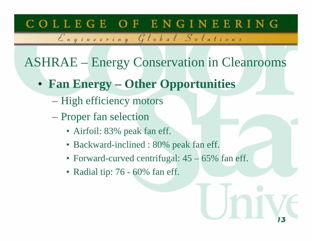
ASHRAE – Energy Conservation in Cleanrooms• Fan Energy – Other Opportunities
– High efficiency motors– Proper fan selection
• Airfoil: 83% peak fan eff. • Backward-inclined : 80% peak fan eff. • Forward-curved centrifugal: 45 – 65% fan eff.• Radial tip: 76 - 60% fan eff.

14
ASHRAE – Energy Conservation in Cleanrooms• Makeup and Exhaust Energy
– Process exhaust requirements in the typical semiconductor facility vary from 1 to 10 cfm per square foot
– Makeup air requirements vary correspondingly, with an added amount for leakage and pressurization
– The energy required to supply the conditioned makeup air can be quite large

15
ASHRAE – Energy Conservation in Cleanrooms• Makeup and Exhaust Energy
– Type of equipment installed normally determines the quantity of exhaust in a given facility
– Heat recovery has been used effectively in process exhaust
• Heat exchanger material must be selected carefully because of the potentially corrosive atmosphere
• Heat recovery equipment has the potential to cross-contaminate products in pharmaceutical facilities.

16
ASHRAE – Energy Conservation in Cleanrooms• Makeup and Exhaust Energy
– Makeup air cannot normally be reduced without decreasing process exhaust
• May be difficult to do because of safety and contamination control requirements.

17
ASHRAE – Energy Conservation in Cleanrooms• Makeup and Exhaust Energy -
Opportunities– Conventional HVAC energy efficiency methods
such as using high-efficiency chillers, good equipment selection, and precise control design can save energy
– One energy-saving method for large facilities is to use multiple-temperature chillers to bring outdoor air temperature to a desired dew point in steps

18
Cleanroom Design - Right Sizing• Determining the initial and projected loads in a
cleanroom is challenging• In some cases (e.g., cooling towers), upsizing
enhances energy efficiency, while in many more, downsizing is the goal.

19
Best Practices for Cleanroom Right-Sizing• Having the design team (owner, engineers, operations
staff) explicitly agree on design loads and any margins to be used in design.
• Sizing equipment to avoid efficiency penalties at part-load conditions. – May involve unequal unit sizing and/or a modular approach.
• Upsizing cooling towers, which represent a very small portion of plant energy consumption, to significantly improve chiller performance and water-side-free-cooling-system operation.
20
Best Practices for Cleanroom Right-Sizing• Utilizing variable-frequency drives (VFDs) to realize
operational savings from oversized fans, pumps, cooling towers, and some types of chillers.
• Designing and operating redundant air handlers, scrubbers, and cooling-tower units in parallel to reduce pressure drop and power requirements and to provide backup capacity.
• Employing methods such as medium-temperature cooling loops and water-side free cooling to eliminate the need for electric chillers during the lowest load periods of the year and, thus, mitigate the impact of oversizing.

21
Best Practices for Cleanroom Right-Sizing• The most efficient systems utilize upsized
passive components (e.g., ducts and pipes), which allow the use of smaller fans and pumps. – The smaller fans and pumps help to offset the
additional first cost of the larger passive components and yield ongoing energy savings.

22
Best Practices for Cleanroom Right-Sizing• Because of reheating, boiler plants commonly
operate throughout the summer. • If reheat requirements cannot be eliminated
through heat recovery, the use of boilers of different sizes with an intelligent seasonal switchover control is recommended to minimize idle-boiler energy use during low-load periods.

23
Minimizing Pressure Drop• Air-delivery-system pressure drop is the design
parameter with the greatest impact on power requirements.

24
Minimizing Pressure Drop• Pressure drop in a duct or air handler is proportional to
the face velocity squared. • Because fan power has a linear relationship with
pressure drop, similar reductions in fan sizing can be obtained with reduced pressure drop.
• Pressure drop in ductwork is inversely proportional to the fifth power of the duct diameter. For example, substituting a 16-in. duct for a 12-in. duct reduces pressure drop by about 75 percent.

25
Opportunities for Minimizing Pressure Drop• Use lower-face-velocity air-handling units• Use low-pressure-drop filters
– Lower-pressure-drop filters often are an option in efforts to reduce energy costs. Larger filter surface area can reduce maintenance costs by allowing longer change intervals.
• Optimally design ductwork and air paths, including open plenums

26
Optimizing Air-Change Rates• Air-change rate is the greatest determinant in
recirculation-air-handling-system fan and motor sizing.
• Current recommendations are not based on scientific findings. – No clear consensus as to the optimum, and real-world
operation varies widely – For ISO Class 5 (Class 100) cleanrooms, 250 to 700 air
changes per hour are recommended. Benchmarking studies, however, have shown that most facilities operate effectively at or below the low end of this range.

27
Optimizing Air-Change Rates• Reducing air-change rate yields energy savings
– A 30% reduction in air-change rate reduces power consumption by 66%
• May also improve cleanliness by minimizing turbulence.
• Allows the downsizing of fans, motors, etc. and corresponding first-cost savings.

28
Optimizing Air-Change Rates• Although the optimum may vary over time, typically, air-change
rate is held constant. • Solution: Demand-controlled filtration. When a cleanroom is
unoccupied, relatively few air changes per hour may be sufficient to maintain cleanliness.
• Airflow setback can be achieved manually, with timers, with occupancy sensors, or possibly by CO2 concentration
• Real-time control monitors particle counts and varies airflow based on actual cleanliness. – Studies in this area have been undertaken by International Sematech, the
Massachusetts Institute of Technology, and Sandia National Laboratories. – In a pilot test at Lawrence Berkeley National Laboratory (LBNL), the
number of air changes per hour was reduced from 594 to 372 without particle counts increasing.

29
Optimizing Exhaust• The suggested exhaust quantities of many equipment
manufacturers are based on rules of thumb and tend to being overstated.
• Typically, a crude face-velocity approach is used to estimate exhaust rates required for containment. Good practice suggests using direct measurements of containment to set exhaust rates.
• In a study by International Sematech, a combined exhaust-airflow reduction of 28% (2,994 cfm to 2,146 scfm) was attained for four classes of semiconductor process tools: wet benches, gas cabinets, ion implanters, and vertical furnaces. At a typical semiconductor facility, such a reduction could amount to savings of more than $33,000 a year.

30
Fume Hood• A typical fume hood, with a sash opening
six feet wide and two to three feet high, circulates air through this sash at 100 feet per minute.
• Flume hoods are typically never turned off
Berkeley Fume Hood• The Berkeley Lab design uses small supply fans located at the top and bottom of the
hood’s face, to push air into the hood and into the user’s breathing zone, setting up a "divider" of air at the sash.
• The air divider helps prevent fumes from reaching a user standing in front of the hood.
• Demonstrated potential to reduce the flow to 30% of a typical hood installation. • See http://ateam.lbl.gov/hightech/fumehood/fhood.html

31
Optimizing Exhaust• The suggested exhaust quantities of many equipment
manufacturers are based on rules of thumb and tend to being overstated.
• Typically, a crude face-velocity approach is used to estimate exhaust rates required for containment. Good practice suggests using direct measurements of containment to set exhaust rates.
• In a study by International Sematech, a combined exhaust-airflow reduction of 28% (2,994 cfm to 2,146 scfm) was attained for four classes of semiconductor process tools: wet benches, gas cabinets, ion implanters, and vertical furnaces. At a typical semiconductor facility, such a reduction could amount to savings of more than $33,000 a year.

32
Optimizing the Use of Chiller Systems and Cooling Towers
• Chiller energy can represent 10-20% of total cleanroom energy use.
• Chillers with VFDs generally operate more efficiently at part load and are more responsive to varying loads than constant-speed-drive chillers with throttling or staging load controls.

33
Optimizing the Use of Chiller Systems and Cooling Towers
• Temperature reset also provides substantial savings opportunities
• Chiller work is proportional to compressor vapor-pressure work. This work can be reduced if chilled-water temperature is raised and/or condenser-water temperature is lowered.
• For centrifugal-compressor-based chillers, a 1°F change in chilled-water-supply temperature can increase efficiency by 1-2 %. The temperature can be reset based on outside-air temperature.

34
Optimizing the Use of Chiller Systems and Cooling Towers
• Temperature reset also provides substantial savings opportunities
• Chiller work is proportional to compressor vapor-pressure work. This work can be reduced if chilled-water temperature is raised and/or condenser-water temperature is lowered.
• For centrifugal-compressor-based chillers, a 1°F change in chilled-water-supply temperature can increase efficiency by 1-2 %. The temperature can be reset based on outside-air temperature.

35
Optimizing the Use of Chiller Systems and Cooling Towers
• In many cleanrooms, chilled-water requirements are best served by medium-temperature (55-70°F) chilled water. – Medium-temperature chillers have smaller compressors, which
lower equipment first cost– Peak loads occur 2-5% of the time over the course of a year. – In a pilot project for a multiple-cleanroom-building campus,
the implementation of a dual-temperature chilled-water system was analyzed. The site had 2,370 tons of makeup-air cooling and 1,530 tons of sensible and process cooling. With 42-F water for low-temperature use and 55-F water for medium-temperature use, approximately $1 million was saved per year, with a payback of two years.

36
Water-Side Free Cooling• A medium-temperature loop greatly expands the
potential for “free cooling”– A low tower approach temperature is critical to
maximizing energy savings. • Chilled-water systems use chillers that typically
operate at 0.5 to 0.7 kW per ton.• But cooling towers operate much more efficiently
– In one benchmark study, cooling tower efficiencies ranged from 0.013 to 0.19 kW per ton

37
Water-Side Free Cooling• Chilled-water reset is key to optimizing free
cooling by increasing the chilled-water-supply set point during mild conditions, when lower-temperature chilled water is not required to meet cooling needs and cooling towers are able to produce the lowest-temperature free-cooling water.
• A VSD should be used for the fan motor to minimize on-off cycling and maximize energy savings.

38
Water-Side Free Cooling• One benchmarked facility had 900 tons of
installed cooling capacity, but was operating at 561 tons.
• A heat exchanger used to isolate condenser water from the process-cooling loop yielded annual savings of 1,140 MWh and a simple payback of 1.2 years.

39
Variable-Speed Pumping• Targets for variable-speed control include hot-
water pumps, chillers, primary-loop chilled-water pumps, secondary-loop chilled-water pumps, condenser-water pumps, and cooling-tower fans
• VSD pumps should be used to control and balance water flows to minimize the need for throttling design. – Should be used to avoid or minimize the use of
booster pumps and close bypasses

40
Variable-Speed Pumping• The observed best practice in overall water-pump
efficiency is: – Primary chilled-water pumps: 0.047 kW per ton. – Secondary chilled-water pumps: 0.019 kW per ton. – Condenser water pumps: 0.089 kW per ton.
• But one benchmarking study identified overall pumping efficiencies of 0.13 to 0.44 kW per ton.

41
Optimizing Vacuum Pumps• Vacuum pumps typically account for 5-10% of a semiconductor
cleanroom facility's total electricity consumption. • Recent advances have improved the efficiency of vacuum pumps
by 50-60%• Integrating process controls allows further savings by
implementation of an idle mode when vacuum is not needed.• Combination provide up to 90% reductions in vacuum-pump
energy use possible. • Variable-speed capability in standby mode is being integrated into
the design of some high-efficiency dry-vacuum pumps. • To implement idle-mode operation, process equipment is being
enabled to send an idle signal to vacuum pumps.

42
Optimizing Vacuum Pumps• In benchmarking studies of six dry-vacuum
pumps serving a semiconductor wafer-etch process, chambers in the process oscillated between "on" and "off" every two minutes.
• The facility had a total of 300 such pumps in use, at an average power demand of 3 kW
• The savings potential of eliminating the on/off cycling is $394,000 per year, which would free up 125 tons of cooling, worth in excess of $100,000.

43
Case Study – Applied Materials: Chilled Water Plant Efficiency Upgrade • A chiller VSD contributes a large potion of energy
savings of $74,000 per year at Applied Materials.• While most cleanroom facilities operate plants with
multiple chillers, they need only a single VSD on the smallest chiller to realize the full benefits.
• Given that plants need not be shutdown and that very little equipment must be altered or replaced, VSDs can be cost effective for virtually all cleanroom plants.
• However, not all existing chillers can be retrofitted with VSDs.

44
Case Study – Genentech: New Energy Efficient Pharmaceutical Manufacturing Cleanroom Facility • A total of 22 separate energy efficiency measures were
performed at the Genentech's Vacaville, CA site. • These efficiency measures have not inhibited Genentech
from complying with strict FDA regulations for pharmaceutical plants.
• The plant it is expected to operate more reliably with these modifications and had an excellent payback of 1.7 years.

45
Case Study – Hine Design: Variable Speed Drive Control of Recirculation Fans for Class 100 Cleanroom• A firm designed and implemented new control logic at the
robotics manufacturing facility of Hine Design in Sunnyvale, California.
• Two specific controls were retrofitted onto the system serving the Class 100 bays to provide the energy saving benefits: Variable speed drives (VSDs) on the FPHs serving the Class 100 bays and a custom control system that schedules the speed of the VSDs based upon occupancy patterns.
• Measurements show an 82% reduction in fan power.

46
Case Study – Motorola: Cleanroom Declassification from Class 10,000 to Class 100,000 • The purpose of this project was to reduce operational costs
and energy use by reducing the classification of the cleanroom at the Motorola AIEG facility in Northbrook, Illinois, from Class 10,000 to Class 100,000.
• To accomplish this airflow was reduced but the ceiling grid and number of HEPA filters remained the same to allow for future flexibility in the cleanrooms.
• Measures were also implemented to improve temperature and humidity control to reduce unnecessary dehumidifying when the outside air is already below the cleanroom humidity setpoint.

47
Case Study – Western Digital: Comprehensive Cleanroom Facility Renovation and Cleanliness Upgrade • Renovate an existing semiconductor
manufacturing plant to create a state-of-the-art hard drive manufacturing facility.
• The renovation called for an increase in floor area from 80,000 to 90,000 square feet and an increase in the cleanliness requirements for the cleanroom from Class 10,000 to Class 10.

48
Case Study – Western Digital: Comprehensive Cleanroom Facility Renovation and Cleanliness Upgrade • Through innovative design and careful
attention to system effects on energy efficiency, the remodeled building used 44% less energy than the original facility.
• WD was also able to eliminate the use of environmentally harmful CFCs used in the chillers

49
Case Study – Western Digital: Comprehensive Cleanroom Facility Renovation and Cleanliness Upgrade • The total renovation cost of the efficient design was
equivalent to the proposed renovation costs of other project bidders who offered standard, less efficient designs.
• Some costs for were lower – fewer, smaller pumps• Project staff estimated that any additional efficiency
related costs paid for themselves within the first year of operation

50
Case Study – Western Digital: Cleanroom Facility Renovation and Cleanliness Upgrade
Recirculation Fan System• Largest single energy users• Lowered pressure drop in ducting and filtration system• Total drop of 1.5 in. W.C. compared to typical drop of 6 – 8 in.• Used low pressure drop filters, low velocity duct design, and
low pressure drop, single pass cooling coils.• Fans were selected to operate at 82% eff. with energy efficient
motors operating at 92% eff.• Each fan was coupled with a variable speed drive: 550 ACH
during peak hours and 100 to 200 ACH on low usage days like holidays and weekends.

51
Case Study – Western Digital: Cleanroom Facility Renovation and Cleanliness UpgradeChillers• Monitored chiller performance for several months -
determined maximum load would be 210 – 200 tons• The existing cooling plant consisted of two 300 ton
CFC refrigerant chillers with an efficiency of 0.65 kW/ton.
• Instead of replacing the chillers, they were retrofitted with a CFC to HCFC conversion kit– Reduced chiller capacity to 250 tons each (still large enough
for one chiller to cover the load and with the second for backup) with a resulting efficiency of 0.61 kW/ton.
– About ¼ the cost of a new chiller

52
Case Study – Western Digital: Cleanroom Facility Renovation and Cleanliness UpgradeCooling Towers• Prior to renovation, large counterflow cooling towers
were used• Replaced with new, more efficient towers• VFDs on fans to enable all cells to operate in parallel
at slower speeds• Parallel operation also saves chiller energy because
lower condenser water supply temperatures are achieved by spreading the water out over all of the cells.

53
Case Study – Western Digital: Cleanroom Facility Renovation and Cleanliness UpgradePumping Systems• Chilled water and condenser water
piping system design focused on low pressure drop
• The original system had pressure drops of around 100 feet, but the new layout was able to reduce that to about 35 feet.
• Smaller and fewer pumps were required
• The new pumps were selected with efficiency in excess of 70% and 92% efficient motors.

54
Case Study – Western Digital: Cleanroom Facility Renovation and Cleanliness UpgradeCompressed Air and Vacuum Systems• The compressed air system was retrofitted to
use refrigerant drying instead of desiccant drying – savings of 15% of the air flow.
• The new vacuum pumps were 30% to 40% more efficient than before– The new units are also controlled by variable speed
drives such that the pump motors require less energy when less vacuum air is required.

55
Case Study – Western Digital: Comprehensive Cleanroom Facility Renovation and Cleanliness Upgrade