industrial hydraulic actuators & valvesnkumbwa.weebly.com/uploads/3/7/1/6/3716285/9... ·...
TRANSCRIPT
1
Eng R. L. Nkumbwa, MSc, BEng, MIET, MEIZ, REng -2010 Copperbelt University
Industrial Hydraulic Actuators & Valves
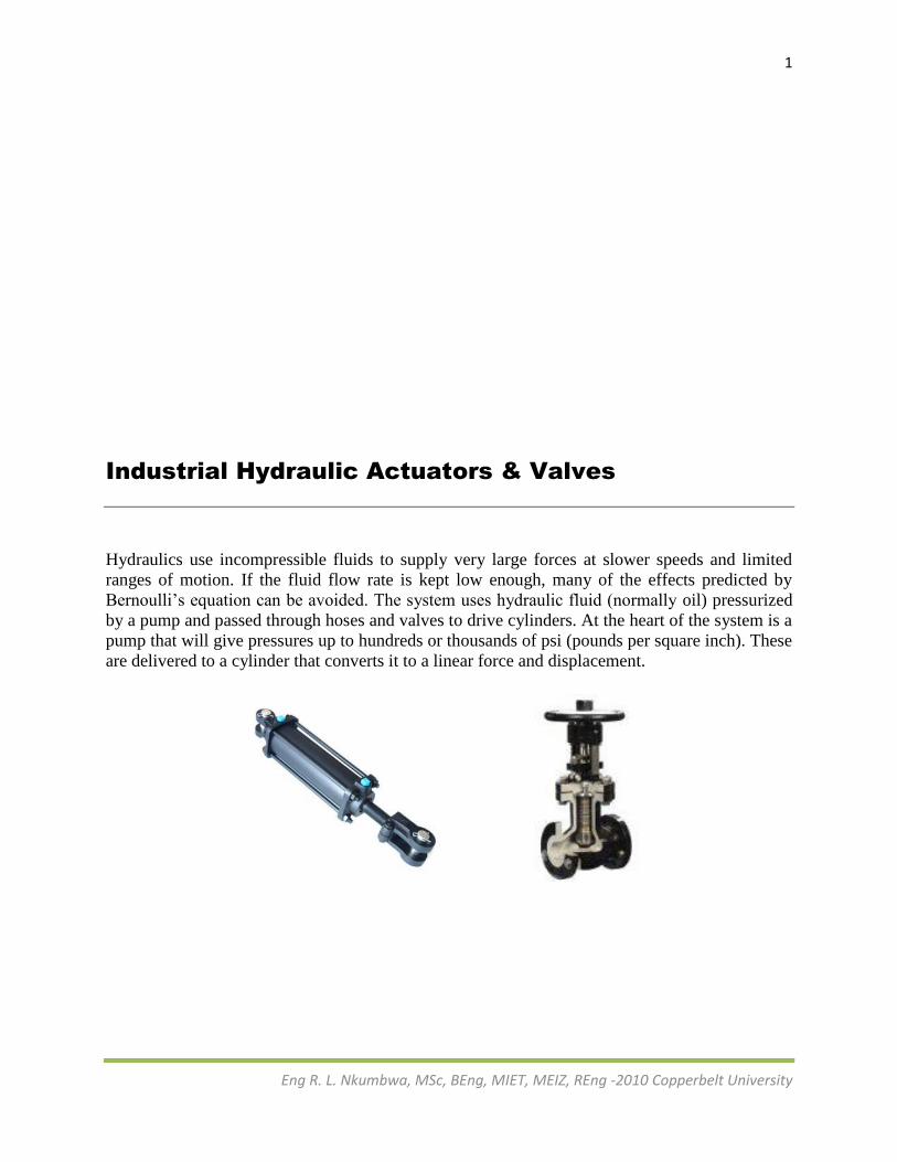
Hydraulics use incompressible fluids to supply very large forces at slower speeds and limited
ranges of motion. If the fluid flow rate is kept low enough, many of the effects predicted by
Bernoulli’s equation can be avoided. The system uses hydraulic fluid (normally oil) pressurized
by a pump and passed through hoses and valves to drive cylinders. At the heart of the system is a
pump that will give pressures up to hundreds or thousands of psi (pounds per square inch). These
are delivered to a cylinder that converts it to a linear force and displacement.
2
Eng R. L. Nkumbwa, MSc, BEng, MIET, MEIZ, REng -2010 Copperbelt University
Hydraulic Actuators
Hydraulic systems normally contain the following components;
Hydraulic Fluid
Oil Reservoir
Pump to Move Oil, and Apply Pressure
Pressure Lines
Control Valves - to regulate fluid flow
Piston and Cylinder - to actuate external mechanisms
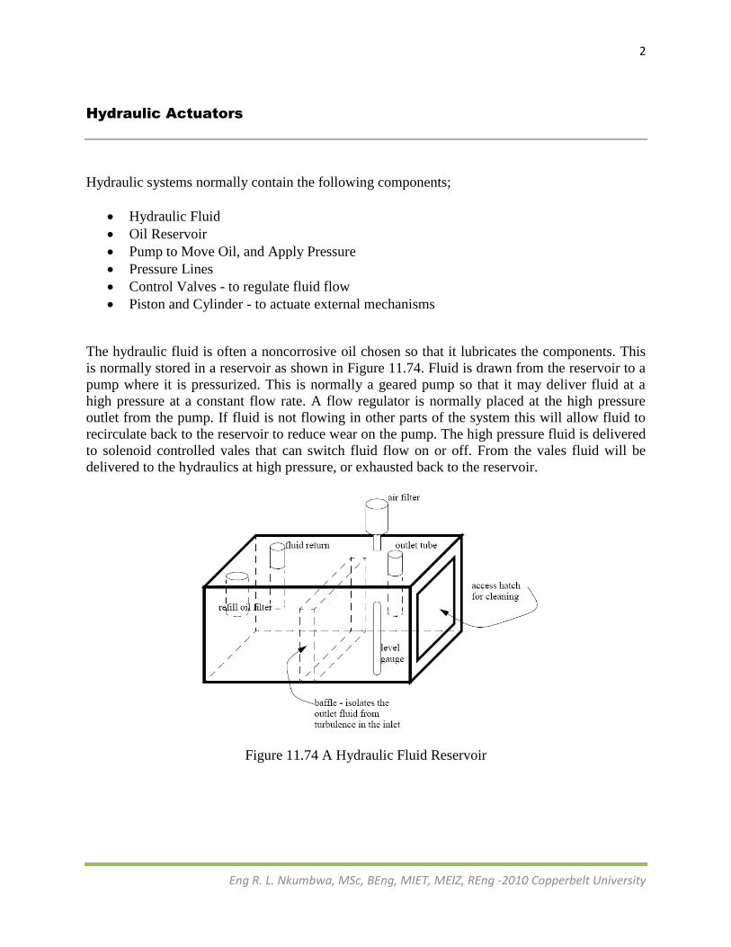
The hydraulic fluid is often a noncorrosive oil chosen so that it lubricates the components. This
is normally stored in a reservoir as shown in Figure 11.74. Fluid is drawn from the reservoir to a
pump where it is pressurized. This is normally a geared pump so that it may deliver fluid at a
high pressure at a constant flow rate. A flow regulator is normally placed at the high pressure
outlet from the pump. If fluid is not flowing in other parts of the system this will allow fluid to
recirculate back to the reservoir to reduce wear on the pump. The high pressure fluid is delivered
to solenoid controlled vales that can switch fluid flow on or off. From the vales fluid will be
delivered to the hydraulics at high pressure, or exhausted back to the reservoir.
Figure 11.74 A Hydraulic Fluid Reservoir
3
Eng R. L. Nkumbwa, MSc, BEng, MIET, MEIZ, REng -2010 Copperbelt University
Directional Control Valves
In order to successfully automate a process it is essential to make sure that the valve itself is
appropriate to handle the special demands of the process and the product in the pipeline. It is the
process or product that should dictate the type of the valve, the closure element of the valve, trim
requirements and material of construction.
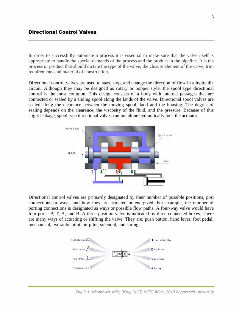
Directional control valves are used to start, stop, and change the direction of flow in a hydraulic
circuit. Although they may be designed as rotary or poppet style, the spool type directional
control is the most common. This design consists of a body with internal passages that are
connected or sealed by a sliding spool along the lands of the valve. Directional spool valves are
sealed along the clearance between the moving spool, land and the housing. The degree of
sealing depends on the clearance, the viscosity of the fluid, and the pressure. Because of this
slight leakage, spool type directional valves can not alone hydraulically lock the actuator.
Directional control valves are primarily designated by their number of possible positions, port
connections or ways, and how they are actuated or energized. For example, the number of
porting connections is designated as ways or possible flow paths. A four-way valve would have
four ports: P, T, A, and B. A three-position valve is indicated by three connected boxes. There
are many ways of actuating or shifting the valve. They are: push button, hand lever, foot pedal,
mechanical, hydraulic pilot, air pilot, solenoid, and spring.

4
Eng R. L. Nkumbwa, MSc, BEng, MIET, MEIZ, REng -2010 Copperbelt University
Directional control valves may also be designated as normally opened or normally closed. These
designations would accompany two-position valves such as the following: spring offset, solenoid
operated, two-way valve normally closed; spring offset, solenoid operated, two-way valve
normally open; spring offset, solenoid operated, three-way valve normally closed; spring offset,
solenoid operated three-way valve normally open.
The spool type directional control valves in industrial applications are sub-plate or manifold
mounted. The porting pattern is industry standard and designed by valve size. Directional control
valve sizing is according to flow capacity which is critical to the proper function of the valve.
Flow capacity of a valve is determined by the port sizes and the pressure drop across the valve.
This mounting pattern and size is designed as a D02 nominal flow 5gpm, D03 nominal flow
10gpm, D05 nominal flow 20gpm, D05H nominal flow 25gpm, D07 nominal flow 30gpm, D08
nominal flow 60gpm, D10 nominal flow 100gpm.
The flow of fluids and air can be controlled with solenoid controlled valves. An example of a
solenoid controlled valve is shown in Figure 11.70. The solenoid is mounted on the side. When
actuated it will drive the central spool left. The top of the valve body has two ports that will be
connected to a device such as a hydraulic cylinder. The bottom of the valve body has a single
pressure line in the center with two exhausts to the side. In the top drawing the power flows in
through the center to the right hand cylinder port. The left hand cylinder port is allowed to exit
through an exhaust port. In the bottom drawing the solenoid is in a new position and the pressure
is now applied to the left hand port on the top, and the right hand port can exhaust. The symbols
to the left of the figure show the schematic equivalent of the actual valve positions. Valves are
also available that allow the valves to be blocked when unused.

5
Eng R. L. Nkumbwa, MSc, BEng, MIET, MEIZ, REng -2010 Copperbelt University
Valve types are listed below. In the standard terminology, the ’n-way’ designates the number of
connections for inlets and outlets. In some cases there are redundant ports for exhausts. The
normally open/closed designation indicates the valve condition when power is off. All of the
valves listed are two position valve, but three position valves are also available.
2-way normally closed - these have one inlet, and one outlet. When unenergized, the
valve is closed. When energized, the valve will open, allowing flow. These are used to
permit flows.
2-way normally open - these have one inlet, and one outlet. When unenergized, the
valve is open, allowing flow. When energized, the valve will close. These are used to
stop flows. When system power is off, flow will be allowed.
3-way normally closed - these have inlet, outlet, and exhaust ports. When unenergized,
the outlet port is connected to the exhaust port. When energized, the inlet is connected to
the outlet port. These are used for single acting cylinders.
3-way normally open - these have inlet, outlet and exhaust ports. When unenergized, the
inlet is connected to the outlet. Energizing the valve connects the outlet to the exhaust.
These are used for single acting cylinders 3-way universal - these have three ports. One
of the ports acts as an inlet or outlet, and is connected to one of the other two, when
energized/unenergized. These can be used to divert flows, or select alternating sources.
4-way - These valves have four ports, two inlets and two outlets. Energizing the valve
causes connection between the inlets and outlets to be reversed. These are used for
double acting cylinders.
Some of the ISO symbols for valves are shown in Figure 11.71. When using the symbols in
drawings the connections are shown for the unenergized state. The arrows show the flow paths in
different positions. The small triangles indicate an exhaust port.
6
Eng R. L. Nkumbwa, MSc, BEng, MIET, MEIZ, REng -2010 Copperbelt University
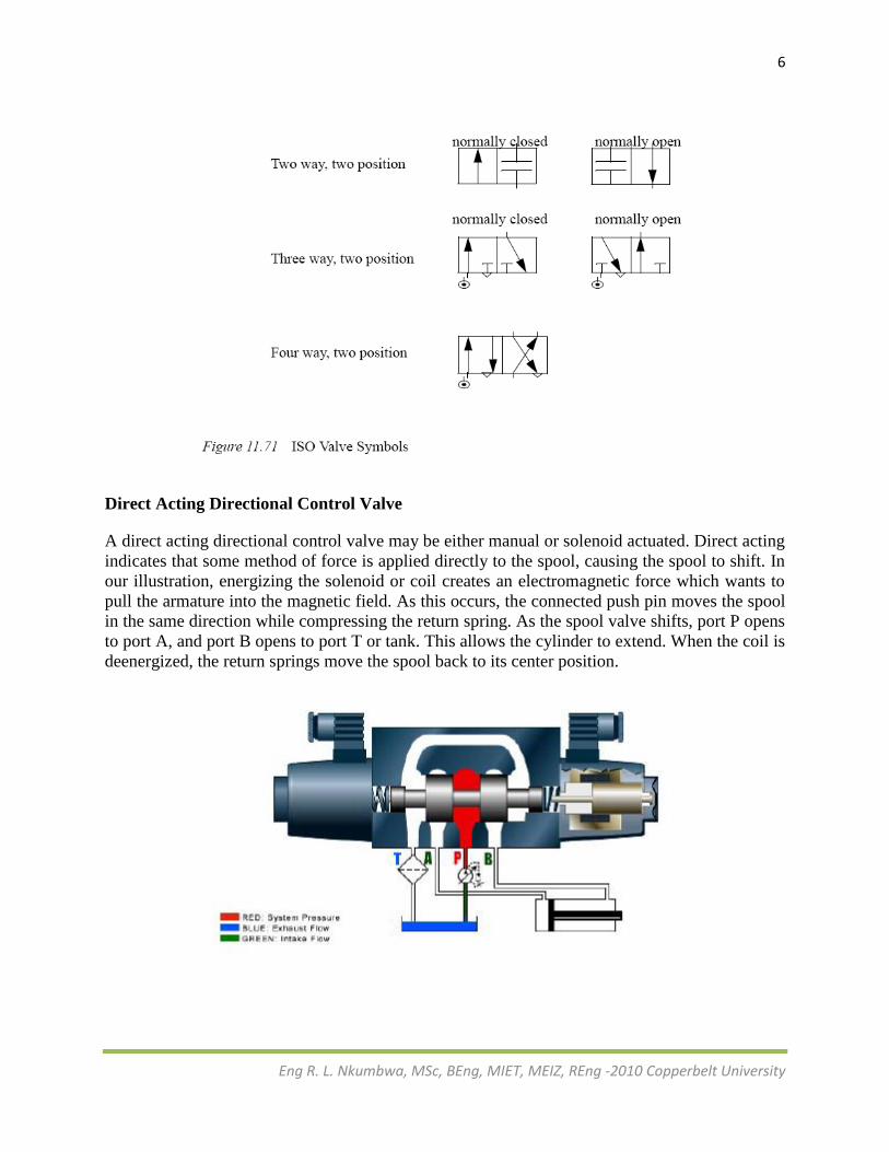
Direct Acting Directional Control Valve
A direct acting directional control valve may be either manual or solenoid actuated. Direct acting
indicates that some method of force is applied directly to the spool, causing the spool to shift. In
our illustration, energizing the solenoid or coil creates an electromagnetic force which wants to
pull the armature into the magnetic field. As this occurs, the connected push pin moves the spool
in the same direction while compressing the return spring. As the spool valve shifts, port P opens
to port A, and port B opens to port T or tank. This allows the cylinder to extend. When the coil is
deenergized, the return springs move the spool back to its center position.
7
Eng R. L. Nkumbwa, MSc, BEng, MIET, MEIZ, REng -2010 Copperbelt University
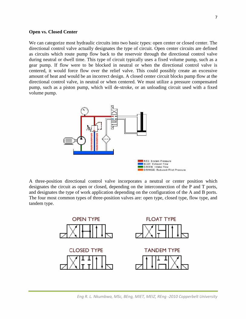
Open vs. Closed Center
We can categorize most hydraulic circuits into two basic types: open center or closed center. The
directional control valve actually designates the type of circuit. Open center circuits are defined
as circuits which route pump flow back to the reservoir through the directional control valve
during neutral or dwell time. This type of circuit typically uses a fixed volume pump, such as a
gear pump. If flow were to be blocked in neutral or when the directional control valve is
centered, it would force flow over the relief valve. This could possibly create an excessive
amount of heat and would be an incorrect design. A closed center circuit blocks pump flow at the
directional control valve, in neutral or when centered. We must utilize a pressure compensated
pump, such as a piston pump, which will de-stroke, or an unloading circuit used with a fixed
volume pump.
A three-position directional control valve incorporates a neutral or center position which
designates the circuit as open or closed, depending on the interconnection of the P and T ports,
and designates the type of work application depending on the configuration of the A and B ports.
The four most common types of three-position valves are: open type, closed type, flow type, and
tandem type.

8
Eng R. L. Nkumbwa, MSc, BEng, MIET, MEIZ, REng -2010 Copperbelt University
This open type configuration connects P, T, A, and B together, giving us an open center and
work force that drain to the tank. This configuration is often used in motor circuits to allow
freewheeling in neutral.
This closed type configuration blocks P, T, A, and B in neutral, giving us a closed center. This
center type is common in parallel circuits where we want to stop and hold a load in mid-cycle.
This float type configuration blocks P while interconnecting A and B ports to T. Because P is
blocked, the circuit becomes closed center. This center type is commonly used in parallel circuits
where we are freewheeling a hydraulic motor in neutral.
9
Eng R. L. Nkumbwa, MSc, BEng, MIET, MEIZ, REng -2010 Copperbelt University
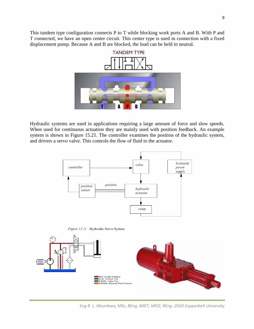
This tandem type configuration connects P to T while blocking work ports A and B. With P and
T connected, we have an open center circuit. This center type is used in connection with a fixed
displacement pump. Because A and B are blocked, the load can be held in neutral.
Hydraulic systems are used in applications requiring a large amount of force and slow speeds.
When used for continuous actuation they are mainly used with position feedback. An example
system is shown in Figure 15.21. The controller examines the position of the hydraulic system,
and drivers a servo valve. This controls the flow of fluid to the actuator.
10
Eng R. L. Nkumbwa, MSc, BEng, MIET, MEIZ, REng -2010 Copperbelt University
Process Control Valves
Whilst a wide variety of valve types exist, this section will concentrate on those which are most
widely used in the automatic control of steam and other industrial fluids. These include valve
types which have linear and rotary spindle movement. Linear types include globe valves and
slide valves. Rotary types include ball valves, butterfly valves, plug valves and their variants.
The first choice to be made is between two-port and three-port valves.
Two-port valves 'throttle' (restrict) the fluid passing through them.
Three-port valves can be used to 'mix' or 'divert' liquid passing through them.
Two-port Valves
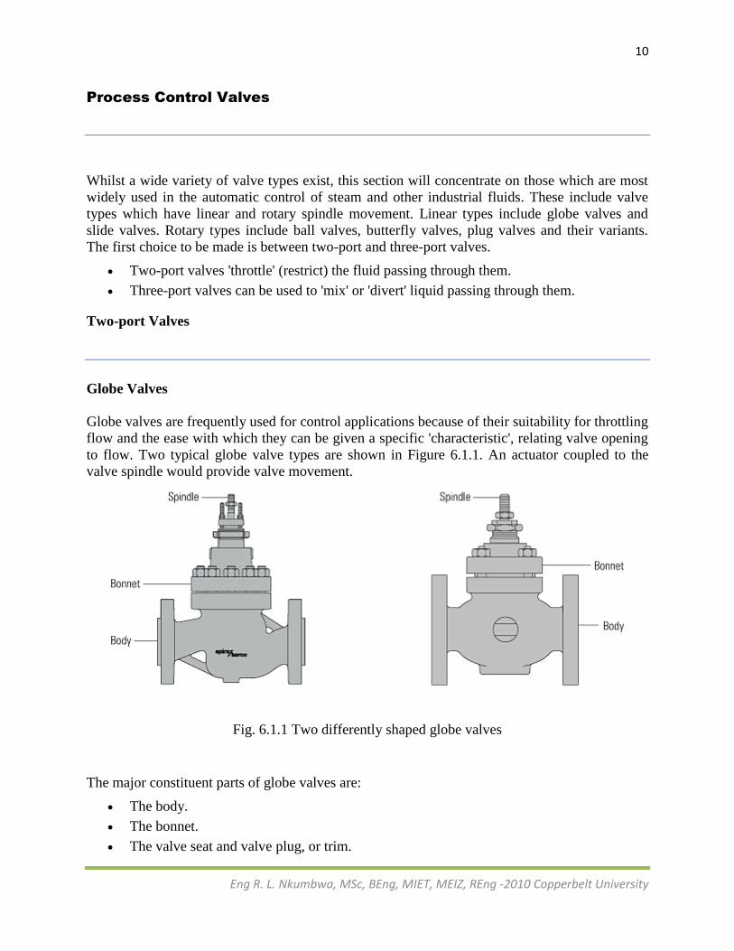
Globe Valves
Globe valves are frequently used for control applications because of their suitability for throttling
flow and the ease with which they can be given a specific 'characteristic', relating valve opening
to flow. Two typical globe valve types are shown in Figure 6.1.1. An actuator coupled to the
valve spindle would provide valve movement.
Fig. 6.1.1 Two differently shaped globe valves
The major constituent parts of globe valves are:
The body.
The bonnet.
The valve seat and valve plug, or trim.

11
Eng R. L. Nkumbwa, MSc, BEng, MIET, MEIZ, REng -2010 Copperbelt University
The valve spindle (which connects to the actuator).
The sealing arrangement between the valve stem and the bonnet.
Figure 6.1.2 is a diagrammatic representation of a single seat two-port globe valve. In this case
the fluid flow is pushing against the valve plug and tending to keep the plug off the valve seat.
Fig. 6.1.2 Flow through a single seat, two-port globe valve
The difference in pressure upstream (P1) and downstream (P2) of the valve, against which the
valve must close, is known as the differential pressure (DP). The maximum differential pressure
against which a valve can close will depend upon the size and type of valve and the actuator
operating it. In broad terms, the force required from the actuator may be determined using
Equation 6.1.1.
6.1.1
Where:
A = Valve seating area (m²)
DP = Differential pressure (kPa)
F = Closing force required (kN)
In a steam system, the maximum differential pressure is usually assumed to be the same as the
upstream absolute pressure. This allows for possible vacuum conditions downstream of the valve
when the valve closes. The differential pressure in a closed water system is the maximum pump
differential head.
12
Eng R. L. Nkumbwa, MSc, BEng, MIET, MEIZ, REng -2010 Copperbelt University
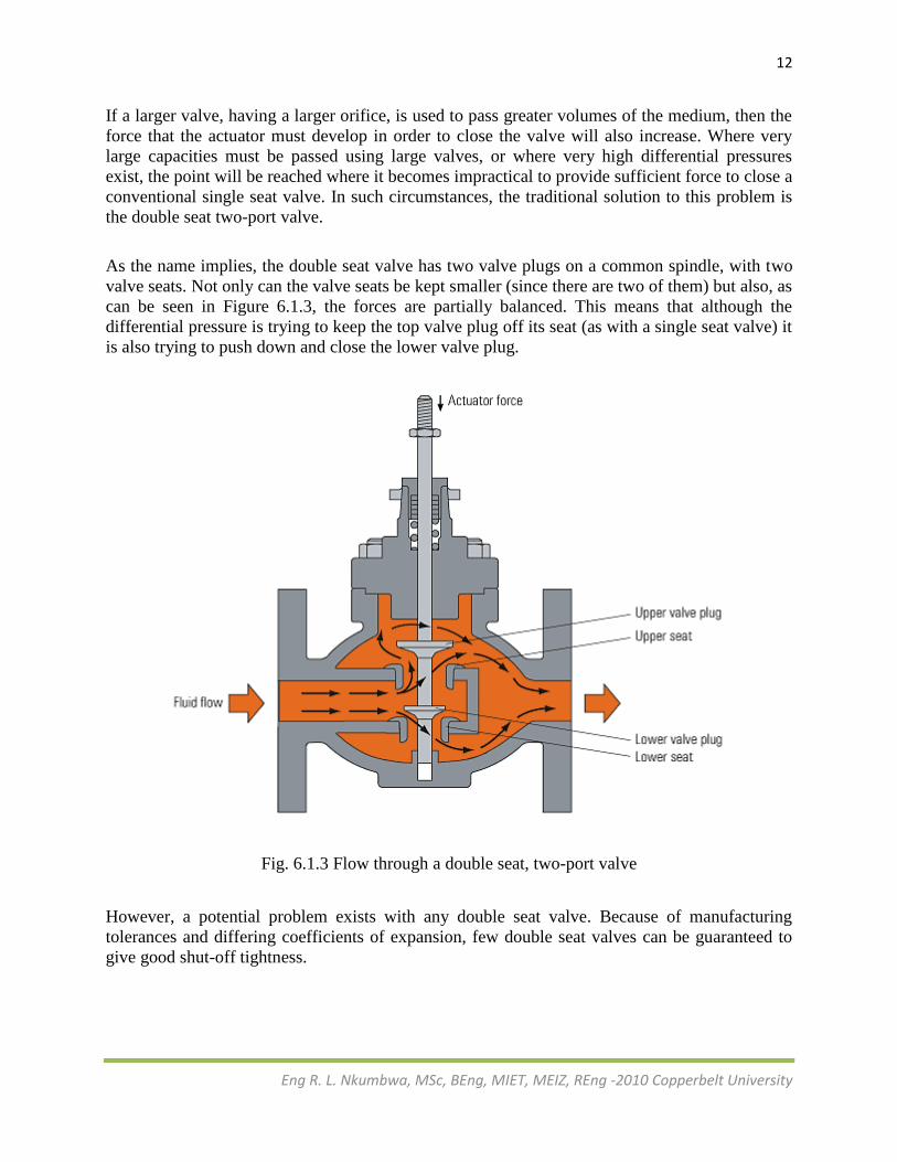
If a larger valve, having a larger orifice, is used to pass greater volumes of the medium, then the
force that the actuator must develop in order to close the valve will also increase. Where very
large capacities must be passed using large valves, or where very high differential pressures
exist, the point will be reached where it becomes impractical to provide sufficient force to close a
conventional single seat valve. In such circumstances, the traditional solution to this problem is
the double seat two-port valve.
As the name implies, the double seat valve has two valve plugs on a common spindle, with two
valve seats. Not only can the valve seats be kept smaller (since there are two of them) but also, as
can be seen in Figure 6.1.3, the forces are partially balanced. This means that although the
differential pressure is trying to keep the top valve plug off its seat (as with a single seat valve) it
is also trying to push down and close the lower valve plug.
Fig. 6.1.3 Flow through a double seat, two-port valve
However, a potential problem exists with any double seat valve. Because of manufacturing
tolerances and differing coefficients of expansion, few double seat valves can be guaranteed to
give good shut-off tightness.

13
Eng R. L. Nkumbwa, MSc, BEng, MIET, MEIZ, REng -2010 Copperbelt University
Three-port Valves
Three-port valves can be used for either mixing or diverting service depending upon the plug and
seat arrangement inside the valve. A simple definition of each function is shown in Figure
6.1.11.
Fig.
14
Eng R. L. Nkumbwa, MSc, BEng, MIET, MEIZ, REng -2010 Copperbelt University
Three-port valve Definition
There are three basic types of three-port valve:
Piston valve type.
Globe plug type.
Rotating shoe type.
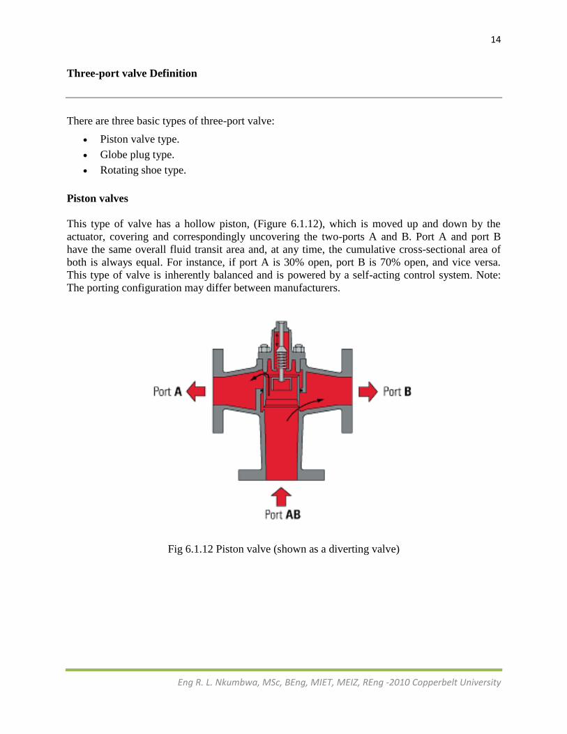
Piston valves
This type of valve has a hollow piston, (Figure 6.1.12), which is moved up and down by the
actuator, covering and correspondingly uncovering the two-ports A and B. Port A and port B
have the same overall fluid transit area and, at any time, the cumulative cross-sectional area of
both is always equal. For instance, if port A is 30% open, port B is 70% open, and vice versa.
This type of valve is inherently balanced and is powered by a self-acting control system. Note:
The porting configuration may differ between manufacturers.
Fig 6.1.12 Piston valve (shown as a diverting valve)
15
Eng R. L. Nkumbwa, MSc, BEng, MIET, MEIZ, REng -2010 Copperbelt University
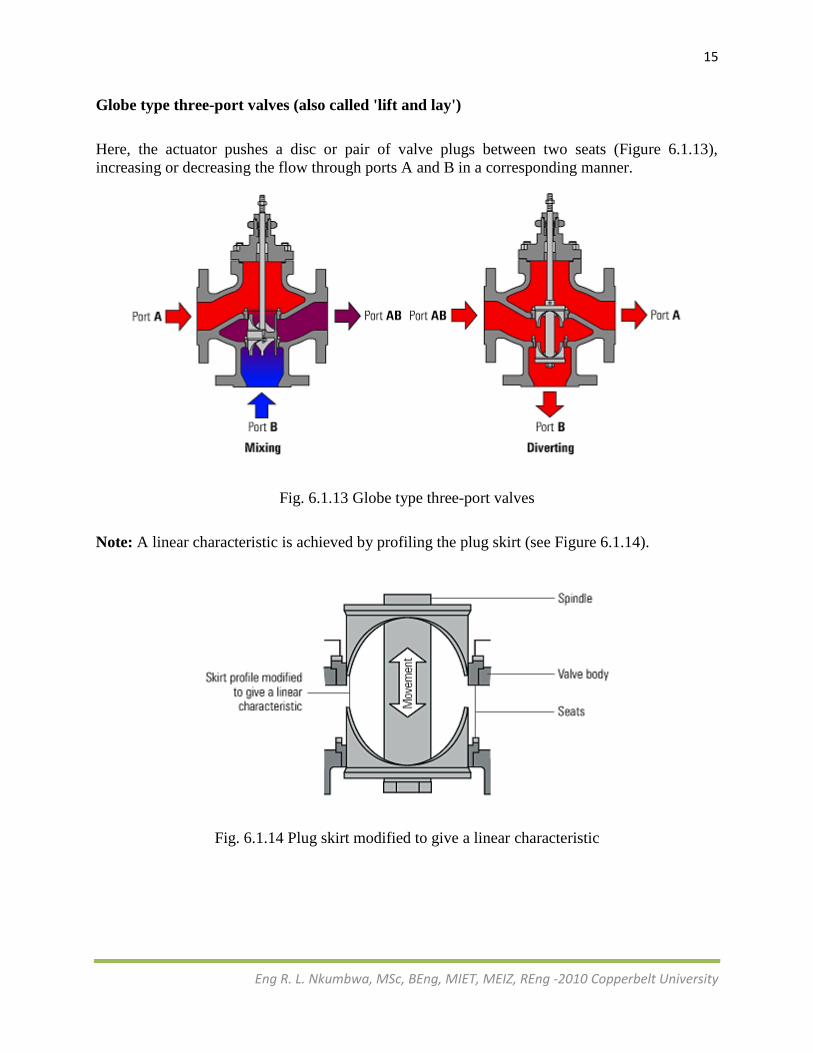
Globe type three-port valves (also called 'lift and lay')
Here, the actuator pushes a disc or pair of valve plugs between two seats (Figure 6.1.13),
increasing or decreasing the flow through ports A and B in a corresponding manner.
Fig. 6.1.13 Globe type three-port valves
Note: A linear characteristic is achieved by profiling the plug skirt (see Figure 6.1.14).
Fig. 6.1.14 Plug skirt modified to give a linear characteristic
16
Eng R. L. Nkumbwa, MSc, BEng, MIET, MEIZ, REng -2010 Copperbelt University
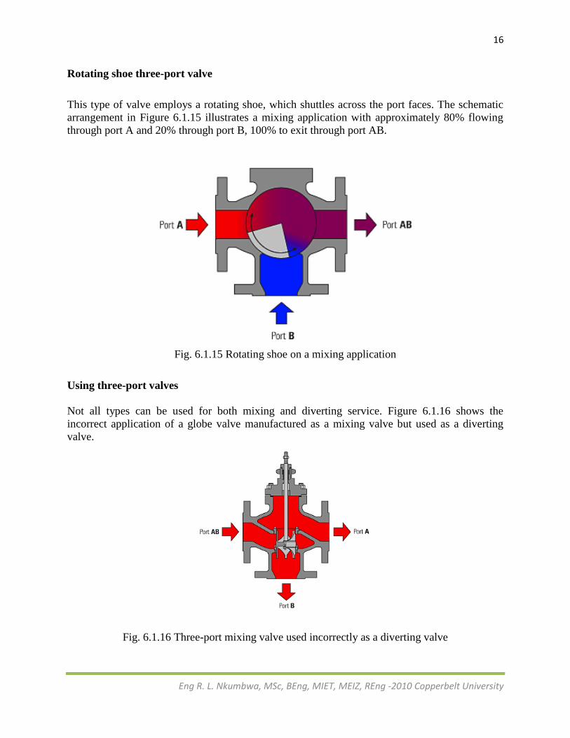
Rotating shoe three-port valve
This type of valve employs a rotating shoe, which shuttles across the port faces. The schematic
arrangement in Figure 6.1.15 illustrates a mixing application with approximately 80% flowing
through port A and 20% through port B, 100% to exit through port AB.
Fig. 6.1.15 Rotating shoe on a mixing application
Using three-port valves
Not all types can be used for both mixing and diverting service. Figure 6.1.16 shows the
incorrect application of a globe valve manufactured as a mixing valve but used as a diverting
valve.
Fig. 6.1.16 Three-port mixing valve used incorrectly as a diverting valve
17
Eng R. L. Nkumbwa, MSc, BEng, MIET, MEIZ, REng -2010 Copperbelt University
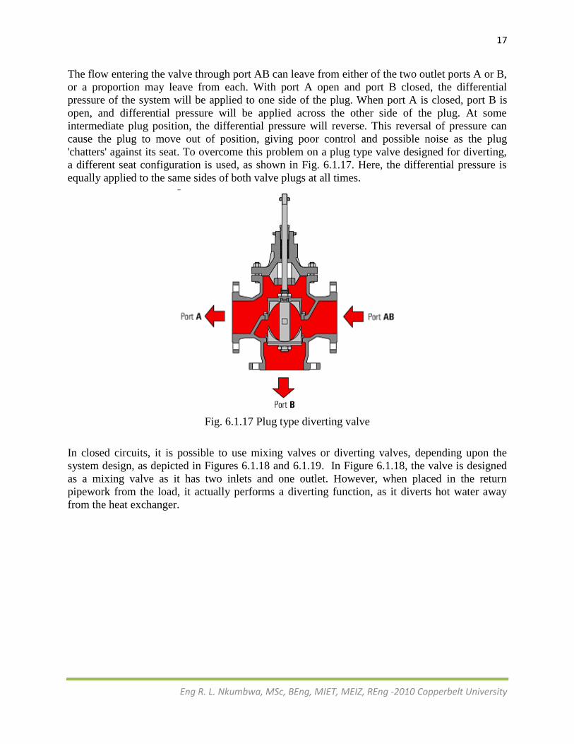
The flow entering the valve through port AB can leave from either of the two outlet ports A or B,
or a proportion may leave from each. With port A open and port B closed, the differential
pressure of the system will be applied to one side of the plug. When port A is closed, port B is
open, and differential pressure will be applied across the other side of the plug. At some
intermediate plug position, the differential pressure will reverse. This reversal of pressure can
cause the plug to move out of position, giving poor control and possible noise as the plug
'chatters' against its seat. To overcome this problem on a plug type valve designed for diverting,
a different seat configuration is used, as shown in Fig. 6.1.17. Here, the differential pressure is
equally applied to the same sides of both valve plugs at all times.
Fig. 6.1.17 Plug type diverting valve
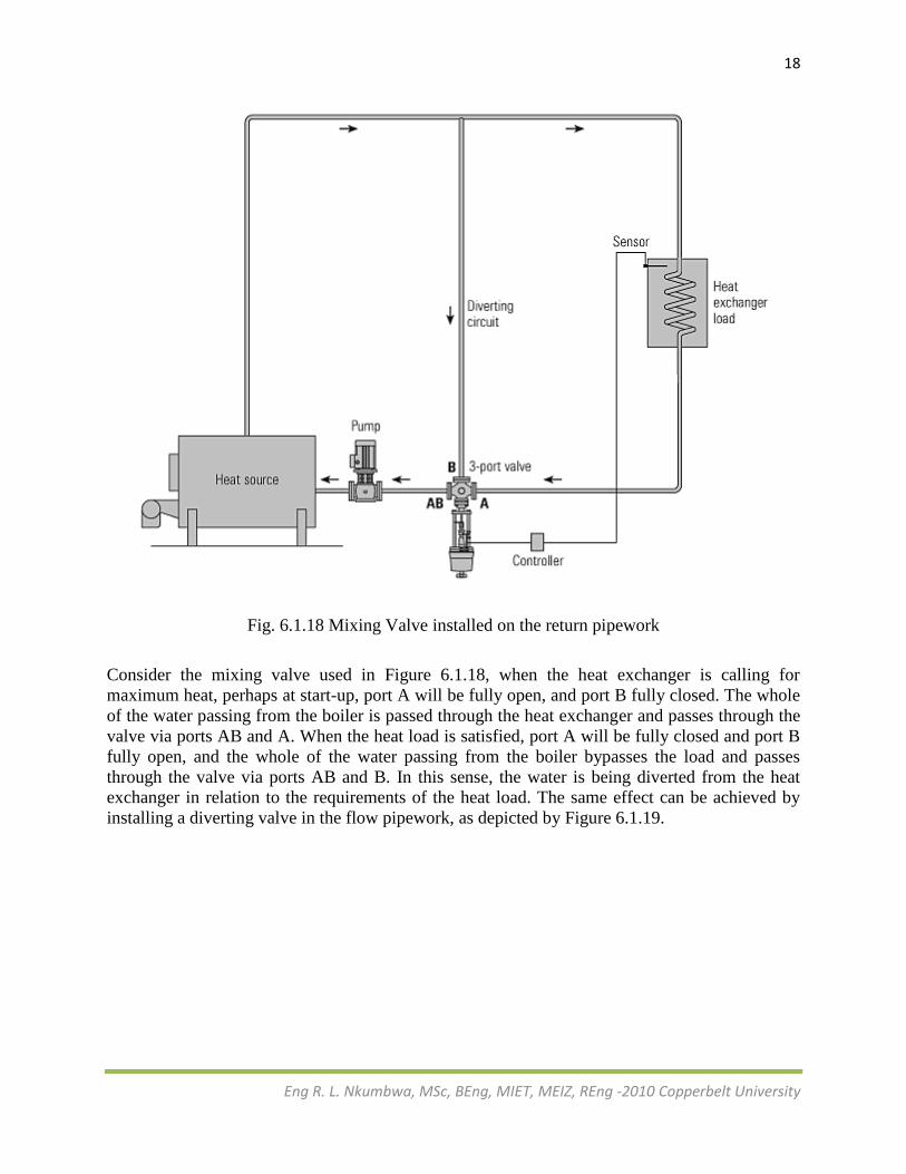
In closed circuits, it is possible to use mixing valves or diverting valves, depending upon the
system design, as depicted in Figures 6.1.18 and 6.1.19. In Figure 6.1.18, the valve is designed
as a mixing valve as it has two inlets and one outlet. However, when placed in the return
pipework from the load, it actually performs a diverting function, as it diverts hot water away
from the heat exchanger.
18
Eng R. L. Nkumbwa, MSc, BEng, MIET, MEIZ, REng -2010 Copperbelt University
Fig. 6.1.18 Mixing Valve installed on the return pipework
Consider the mixing valve used in Figure 6.1.18, when the heat exchanger is calling for
maximum heat, perhaps at start-up, port A will be fully open, and port B fully closed. The whole
of the water passing from the boiler is passed through the heat exchanger and passes through the
valve via ports AB and A. When the heat load is satisfied, port A will be fully closed and port B
fully open, and the whole of the water passing from the boiler bypasses the load and passes
through the valve via ports AB and B. In this sense, the water is being diverted from the heat
exchanger in relation to the requirements of the heat load. The same effect can be achieved by
installing a diverting valve in the flow pipework, as depicted by Figure 6.1.19.

19
Eng R. L. Nkumbwa, MSc, BEng, MIET, MEIZ, REng -2010 Copperbelt University
Fig. 6.1.19 Diverting valve installed on the flow pipework

20
Eng R. L. Nkumbwa, MSc, BEng, MIET, MEIZ, REng -2010 Copperbelt University
Three-port Valves Process Design
A three-port valve can be considered as a constant flowrate valve, because, whether it is used to
mix or divert, the total flow through the valve remains constant. In applications where such
valves are employed, the water circuit will naturally split into two separate loops, constant
flowrate and variable flowrate. The simple system shown in Figure 6.3.6 depicts a mixing valve
maintaining a constant flowrate of water through the 'load' circuit. In a heating system, the load
circuit refers to the circuit containing the heat emitters, such as radiators in a building.
Fig. 6.3.6 Mixing valve (constant flowrate, variable temperature)
The amount of heat emitted from the radiators depends on the temperature of the water flowing
through the load circuit, which in turn, depends upon how much water flows into the mixing
valve from the boiler, and how much is returned to the mixing valve via the balancing line.
It is necessary to fit a balance valve in the balance line. The balance valve is set to maintain the
same resistance to flow in the variable flowrate part of the piping network, as illustrated in
Figures 6.3.6 and 6.3.7. This helps to maintain smooth regulation by the valve as it changes
position. In practice, the mixing valve is sometimes designed not to shut port A completely; this
ensures that a minimum flowrate will pass through the boiler at all times under the influence of
the pump. Alternatively, the boiler may employ a primary circuit, which is also pumped to allow
a constant flow of water through the boiler, preventing the boiler from overheating. The simple
system shown in Figure 6.3.7 shows a diverting valve maintaining a constant flowrate of water
through the constant flowrate loop. In this system, the load circuit receives a varying flowrate of
water depending on the valve position. The temperature of water in the load circuit will be
constant, as it receives water from the boiler circuit whatever the valve position. The amount of

21
Eng R. L. Nkumbwa, MSc, BEng, MIET, MEIZ, REng -2010 Copperbelt University
heat available to the radiators depends on the amount of water flowing through the load circuit,
which in turn, depends on the degree of opening of the diverting valve.
Fig. 6.3.7 Diverting valve (constant temperature in load circuit with variable flow)
The effect of not fitting and setting a balance valve can be seen in Figure 6.3.8. This shows the
pump curve and system curve changing with valve position. The two system curves illustrate the
difference in pump pressure required between the load circuit P1 and the bypass circuit P2, as a
result of the lower resistance offered by the balancing circuit, if no balance valve is fitted. If the
circuit is not correctly balanced then short-circuiting and starvation of any other sub-circuits (not
shown) can result, and the load circuit may be deprived of water.
Fig. 6.3.8 Effect of not fitting a balance valve

22
Eng R. L. Nkumbwa, MSc, BEng, MIET, MEIZ, REng -2010 Copperbelt University
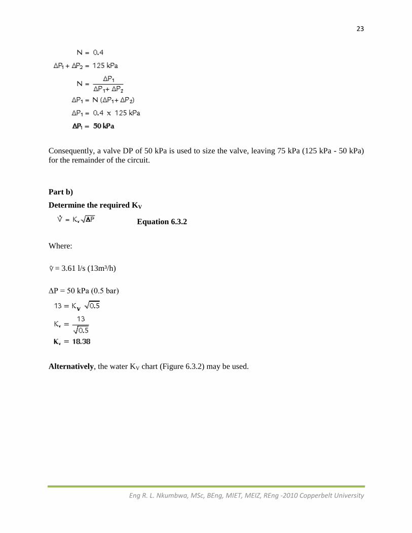
Valve Authority
Valve authority may be determined using Equation 6.3.4.
6.3.4
Where:
N = Valve authority
ΔP1 = Pressure drop across a fully open
control valve
ΔP2 = Pressure drop across the remainder of the
circuit
ΔP1 + P2
= Pressure drop across the whole circuit
The value of N should be near to 0.5 (but not greater than), and certainly not lower than 0.2.
This will ensure that each increment of valve movement will have an effect on the flowrate
without excessively increasing the cost of pumping power.
Example
A circuit has a total pressure drop (ΔP1 + ΔP2) of 125 kPa, which includes the control valve.
a) If the control valve must have a valve authority (N) of 0.4, what pressure drop is used to size
the valve?
b) If the circuit/system flowrate ( ) is 3.61 l/s, what is the required valve Kv?
Part a)
Determine the ΔP
Equation 6.3.4
23
Eng R. L. Nkumbwa, MSc, BEng, MIET, MEIZ, REng -2010 Copperbelt University
Consequently, a valve DP of 50 kPa is used to size the valve, leaving 75 kPa (125 kPa - 50 kPa)
for the remainder of the circuit.
Part b)
Determine the required KV
Equation 6.3.2
Where:
= 3.61 l/s (13m³/h)
ΔP = 50 kPa (0.5 bar)
Alternatively, the water KV chart (Figure 6.3.2) may be used.

24
Eng R. L. Nkumbwa, MSc, BEng, MIET, MEIZ, REng -2010 Copperbelt University
Fig. 6.3.2 Water Kv chart
25
Eng R. L. Nkumbwa, MSc, BEng, MIET, MEIZ, REng -2010 Copperbelt University
Cavitation and Flashing
Other symptoms sometimes associated with water flowing through two-port valves are due to
'cavitation' and 'flashing'.
Cavitation in liquids
Cavitation can occur in valves controlling the flow of liquid if the pressure drop and hence the
velocity of the flow is sufficient to cause the local pressure after the valve seat to drop below the
vapour pressure of the liquid. This causes vapour bubbles to form. Pressure may then recover
further downstream causing vapour bubbles to rapidly collapse. As the bubbles collapse very
high local pressures are generated which, if adjacent to metal surfaces can cause damage to the
valve trim, the valve body or downstream pipework. This damage typically has a very rough,
porous or sponge-like appearance which is easily recognised. Other effects which may be noticed
include noise, vibration and accelerated corrosion due to the repeated removal of protective
oxide layers.
Cavitation will tend to occur in control valves:
On high pressure drop applications, due to the high velocity in the valve seat area causing
a local reduction in pressure.
Where the downstream pressure is not much higher than the vapour pressure of the
liquid. This means that cavitation is more likely with hot liquids and/or low downstream
pressure.
Cavitation damage is likely to be more severe with larger valves sizes due to the increased power
in the flow.
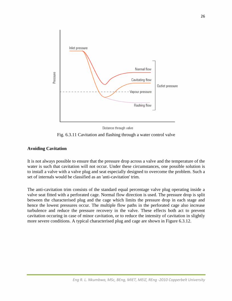
Flashing in liquids
Flashing is a similar symptom to cavitation, but occurs when the valve outlet pressure is lower
than the vapour pressure condition. Under these conditions, the pressure does not recover in the
valve body, and the vapour will continue to flow into the connecting pipe. The vapour pressure
will eventually recover in the pipe and the collapsing vapour will cause noise similar to that
experienced with cavitation. Flashing will reduce the capacity of the valve due to the throttling
effect of the vapour having a larger volume than the water. Figure 6.3.11 illustrates typical
pressure profiles through valves due to the phenomenon of cavitation and flashing.
26
Eng R. L. Nkumbwa, MSc, BEng, MIET, MEIZ, REng -2010 Copperbelt University
Fig. 6.3.11 Cavitation and flashing through a water control valve
Avoiding Cavitation
It is not always possible to ensure that the pressure drop across a valve and the temperature of the
water is such that cavitation will not occur. Under these circumstances, one possible solution is
to install a valve with a valve plug and seat especially designed to overcome the problem. Such a
set of internals would be classified as an 'anti-cavitation' trim.
The anti-cavitation trim consists of the standard equal percentage valve plug operating inside a
valve seat fitted with a perforated cage. Normal flow direction is used. The pressure drop is split
between the characterised plug and the cage which limits the pressure drop in each stage and
hence the lowest pressures occur. The multiple flow paths in the perforated cage also increase
turbulence and reduce the pressure recovery in the valve. These effects both act to prevent
cavitation occuring in case of minor cavitation, or to reduce the intensity of cavitation in slightly
more severe conditions. A typical characterised plug and cage are shown in Figure 6.3.12.

27
Eng R. L. Nkumbwa, MSc, BEng, MIET, MEIZ, REng -2010 Copperbelt University
Fig. 6.3.12 A typical two-port valve anti-cavitation trim
The pressure drop is split between the orifice pass area and the cage. In many applications the
pressure does not drop below the vapour pressure of the liquid and cavitation is avoided. Figure
6.3.12 shows how the situation is improved.
Fig. 6.3.13 Cavitation is alleviated by anti-cavitation valve trim

28
Eng R. L. Nkumbwa, MSc, BEng, MIET, MEIZ, REng -2010 Copperbelt University
Example
A boiler water level control system - a water system with a two-port valve.
In systems of this type (an example is shown in Figure 6.5.6), where a two-port feedwater
control valve varies the flowrate of water, the pressure drop across the control valve will vary
with flow. This variation is caused by:
The pump characteristic. As flowrate is decreased, the differential pressure between the
pump and boiler is increased.
The frictional resistance of the pipework changes with flowrate. The head lost to friction
is proportional to the square of the velocity.
The pressure within the boiler will vary as a function of the steam load, the type of burner
control system and its mode of control.
Fig. 6.5.6 A modulating boiler water level control system (not to scale)
29
Eng R. L. Nkumbwa, MSc, BEng, MIET, MEIZ, REng -2010 Copperbelt University
Selecting Valve Type
When speaking of valves, it's easy to get lost in the terminology. Valve types are used to
describe the mechanical characteristics and geometry (Ex/gate, ball, globe valves). We'll use
valve control to refer to how the valve travel or stroke (openness) relates to the flow. So how do
you decide which valve control to use? Here are some rules of thumb for each one:
Equal Percentage: equal increments of valve travel produce an equal percentage in
flow change
o Used in processes where large changes in pressure drop are expected
o Used in processes where a small percentage of the total pressure drop is permitted
by the valve
o Used in temperature and pressure control loops
Linear: valve travel is directly proportional to the valve stoke
o Used in liquid level or flow loops
o Used in systems where the pressure drop across the valve is expected to remain
fairly constant (ie. steady state systems)
Quick Opening: large increase in flow with a small change in valve stroke
o Used for frequent on-off service
o Used for processes where "instantly" large flow is needed (ie. safety systems or
cooling water systems)

30
Eng R. L. Nkumbwa, MSc, BEng, MIET, MEIZ, REng -2010 Copperbelt University
Common Types of Process Control Valves
Now that we've covered the various types of valve control, we'll take a look at the most common
valve types.
Gate Valves
Best Suited Control: Quick Opening
Recommended Uses:
1. Fully open/closed, non-throttling
2. Infrequent operation
3. Minimal fluid trapping in line
Applications: Oil, gas, air, slurries, heavy liquids, steam, noncondensing
gases, and corrosive liquids
Advantages: Disadvantages:
1. High capacity 1. Poor control
2. Tight shutoff 2. Cavitate at low pressure drops
3. Low cost 3. Cannot be used for throttling
4. Little resistance to flow
Globe Valves
Best Suited Control: Linear and Equal percentage
Recommended Uses:
1. Throttling service/flow regulation
2. Frequent operation
Applications: Liquids, vapors, gases, corrosive substances, slurries
Advantages: Disadvantages:
1. Efficient throttling 1. High pressure drop
2. Accurate flow control 2. More expensive than other valves
3. Available in multiple ports
31
Eng R. L. Nkumbwa, MSc, BEng, MIET, MEIZ, REng -2010 Copperbelt University
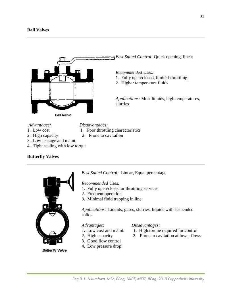
Ball Valves
Best Suited Control: Quick opening, linear
Recommended Uses:
1. Fully open/closed, limited-throttling
2. Higher temperature fluids
Applications: Most liquids, high temperatures,
slurries
Advantages: Disadvantages:
1. Low cost 1. Poor throttling characteristics
2. High capacity 2. Prone to cavitation
3. Low leakage and maint.
4. Tight sealing with low torque
Butterfly Valves
Best Suited Control: Linear, Equal percentage
Recommended Uses:
1. Fully open/closed or throttling services
2. Frequent operation
3. Minimal fluid trapping in line
Applications: Liquids, gases, slurries, liquids with suspended
solids
Advantages: Disadvantages:
1. Low cost and maint. 1. High torque required for control
2. High capacity 2. Prone to cavitation at lower flows
3. Good flow control
4. Low pressure drop

32
Eng R. L. Nkumbwa, MSc, BEng, MIET, MEIZ, REng -2010 Copperbelt University
Valve Selection
When selecting valves there are a number of details that should be considered, as listed below:
Pipe size - inlets and outlets are typically threaded to accept NPT (national pipe thread).
Flow rate - the maximum flow rate is often provided to hydraulic valves.
Operating pressure - a maximum operating pressure will be indicated. Some valves will
also require a minimum pressure to operate.
Electrical - the solenoid coil will have a fixed supply voltage (AC or DC) and current.
Response time - this is the time for the valve to fully open/close. Typical times for valves
range from 5ms to 150ms.
Enclosure - the housing for the valve will be rated as,
o type 1 or 2 - for indoor use, requires protection against splashes
o type 3 - for outdoor use, will resists some dirt and weathering
o type 3R or 3S or 4 - water and dirt tight
o type 4X - water and dirt tight, corrosion resistant
Control Valve Selection
Sizing flow valves is a science with many rules of thumb that few people agree on. Here
standard procedure for sizing a valve as well as helping to select the appropriate type of valve is
illustrated.
STEP #1: Define the System
The system is pumping water from one tank to another through a piping system with a total
pressure drop of 150 psi. The fluid is water at 70 0F. Design (maximum) flowrate of 150 gpm,
operating flowrate of 110 gpm, and a minimum flowrate of 25 gpm. The pipe diameter is 3
inches. At 70 0F, water has a specific gravity of 1.0.
Key Variables: Total pressure drop, design flow, operating flow, minimum flow, pipe diameter,
specific gravity
STEP #2: Define a maximum allowable pressure drop for the valve
When defining the allowable pressure drop across the valve, you should first investigate the
pump. What is its maximum available head? Remember that the system pressure drop is limited
by the pump. Essentially the Net Positive Suction Head Available (NPSHA) minus the Net
Positive Suction Head Required (NPSHR) is the maximum available pressure drop for the valve
to use and this must not be exceeded or another pump will be needed. It's important to remember
the trade off, larger pressure drops increase the pumping cost (operating) and smaller pressure
drops increase the valve cost because a larger valve is required (capital cost).
33
Eng R. L. Nkumbwa, MSc, BEng, MIET, MEIZ, REng -2010 Copperbelt University
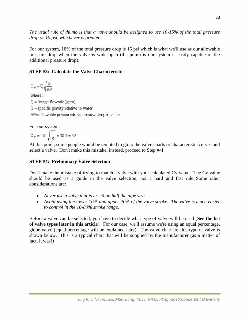
The usual rule of thumb is that a valve should be designed to use 10-15% of the total pressure
drop or 10 psi, whichever is greater.
For our system, 10% of the total pressure drop is 15 psi which is what we'll use as our allowable
pressure drop when the valve is wide open (the pump is our system is easily capable of the
additional pressure drop).
STEP #3: Calculate the Valve Characteristic
For our system,
At this point, some people would be tempted to go to the valve charts or characteristic curves and
select a valve. Don't make this mistake, instead, proceed to Step #4!
STEP #4: Preliminary Valve Selection
Don't make the mistake of trying to match a valve with your calculated Cv value. The Cv value
should be used as a guide in the valve selection, not a hard and fast rule. Some other
considerations are:
Never use a valve that is less than half the pipe size
Avoid using the lower 10% and upper 20% of the valve stroke. The valve is much easier
to control in the 10-80% stroke range.
Before a valve can be selected, you have to decide what type of valve will be used (See the list
of valve types later in this article). For our case, we'll assume we're using an equal percentage,
globe valve (equal percentage will be explained later). The valve chart for this type of valve is
shown below. This is a typical chart that will be supplied by the manufacturer (as a matter of
fact, it was!)
34
Eng R. L. Nkumbwa, MSc, BEng, MIET, MEIZ, REng -2010 Copperbelt University
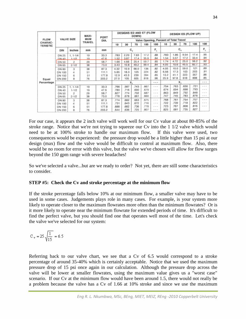
For our case, it appears the 2 inch valve will work well for our Cv value at about 80-85% of the
stroke range. Notice that we're not trying to squeeze our Cv into the 1 1/2 valve which would
need to be at 100% stroke to handle our maximum flow. If this valve were used, two
consequences would be experienced: the pressure drop would be a little higher than 15 psi at our
design (max) flow and the valve would be difficult to control at maximum flow. Also, there
would be no room for error with this valve, but the valve we've chosen will allow for flow surges
beyond the 150 gpm range with severe headaches!
So we've selected a valve...but are we ready to order? Not yet, there are still some characteristics
to consider.
STEP #5: Check the Cv and stroke percentage at the minimum flow
If the stroke percentage falls below 10% at our minimum flow, a smaller valve may have to be
used in some cases. Judgements plays role in many cases. For example, is your system more
likely to operate closer to the maximum flowrates more often than the minimum flowrates? Or is
it more likely to operate near the minimum flowrate for extended periods of time. It's difficult to
find the perfect valve, but you should find one that operates well most of the time. Let's check
the valve we've selected for our system:
Referring back to our valve chart, we see that a Cv of 6.5 would correspond to a stroke
percentage of around 35-40% which is certainly acceptable. Notice that we used the maximum
pressure drop of 15 psi once again in our calculation. Although the pressure drop across the
valve will be lower at smaller flowrates, using the maximum value gives us a "worst case"
scenario. If our Cv at the minimum flow would have been around 1.5, there would not really be
a problem because the valve has a Cv of 1.66 at 10% stroke and since we use the maximum

35
Eng R. L. Nkumbwa, MSc, BEng, MIET, MEIZ, REng -2010 Copperbelt University
pressure drop, our estimate is conservative. Essentially, at lower pressure drops, Cv would only
increase which in this case would be advantageous.
STEP #6: Check the gain across applicable Flow Rates
Gain is defined as:
Now, at our three flowrates:
Qmin = 25 gpm
Qop = 110 gpm
Qdes = 150 gpm
We have corresponding Cv values of 6.5, 28, and 39. The corresponding stroke percentages are
35%, 73%, and 85% respectively. Now we construct the following table:
Flow
(gpm)
Stroke
(%)
Change in flow
(gpm)
Change in Stroke (%)
25 35 110-25 = 85 73-35 = 38
110 73
150 85 150-110 = 40 85-73 = 12
Gain #1 = 85/38 = 2.2
Gain #2 = 40/12 = 3.3
The difference between these values should be less than 50% of the higher value.
0.5 (3.3) = 1.65 and 3.3 - 2.2 = 1.10. Since 1.10 is less than 1.65, there should be no problem in
controlling the valve. Also note that the gain should never be less than 0.50. So for our case, I
believe our selected valve will do nicely!
OTHER NOTES
Another valve characteristic that can be examined is called the choked flow. The relation uses
the FL value found on the valve chart. I recommend checking the choked flow for vastly
different maximum and minimum flowrates. For example if the difference between the
maximum and minimum flows is above 90% of the maximum flow, you may want to check the
choked flow. Usually, the rule of thumb for determining the maximum pressure drop across the
valve also helps to avoid choking flow.

36
Eng R. L. Nkumbwa, MSc, BEng, MIET, MEIZ, REng -2010 Copperbelt University