industrial steam system optimization experts training · plant to conduct a steam system...
TRANSCRIPT

1
Industrial Steam System Optimization
Experts Training
Ven Venkatesan, P.E., CEM - VGA Engineering Consultants Inc
Greg Harrell, Ph.D., P.E. - Energy Management Services, USA
Riyaz Papar, P.E., CEM - Hudson Technologies Company, USA
conducted by
Oliver Fischer , DI MSc
Engineering Consultant / SEWEN - ENERGY Management & Engineering
&
Alexander Antomoshkin
UNIDO Lead National Expert Russia, NCPC Technical Director
developed by :
2
Acknowledgments
UNIDO Team – Vienna, Austria
UNIDO - Project Management Unit, Tehran - Iran
United States Department of Energy, USA
Oak Ridge National Laboratory, USA
California Energy Commission, USA
Del Monte Foods, Modesto Plant, CA, USA
Phillips Petroleum, Teesside. UK
Terra Nitrogen Ltd. Teesside, UK

3
Training Objectives
To train end-users and consulting engineers to become national experts for assessing and optimizing steam systems
Help industry optimize steam systems and achieve energy and cost savings through
• Proper operation and controls
• System maintenance
• Appropriate process uses of steam
• Cogeneration and
• Application of state-of-the-art technologies
4
Training Objectives
To conduct field assessments and identify projects to demonstrate
actual energy and cost savings achievable using the Systems
Approach
Build expertise in the use of US DOE publicly available steam system
optimization assessment software tools

5
Training Outline
Day 3
Review of topics from 2-Day User Training
ASME Steam Standard & Assessment Protocol
Student Exercise - An industrial Steam System energy assessment
Elements of a Steam Energy Assessment Report
Evaluating certain steam system configurations
• Extraction turbines
• Waste heat recovery
• Heat exchangers
• Thermocompressors
• Absorption chillers
• ORC (Organic Rankine Cycle) Power Generators
6
Training Outline
Day 3
Presentation of select Case Studies from SSO
HOST Plant Information – Overview of the plant to be assessed
Instrumentation Briefing and Demonstration of all the instruments to be used in the assessment
Tools & Resources
Conclusions
7
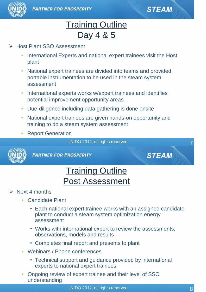
Training Outline
Day 4 & 5
Host Plant SSO Assessment
• International Experts and national expert trainees visit the Host
plant
• National expert trainees are divided into teams and provided
portable instrumentation to be used in the steam system
assessment
• International experts works w/expert trainees and identifies
potential improvement opportunity areas
• Due-diligence including data gathering is done onsite
• National expert trainees are given hands-on opportunity and
training to do a steam system assessment
• Report Generation
8
Training Outline
Post Assessment Next 4 months
• Candidate Plant
• Each national expert trainee works with an assigned candidate plant to conduct a steam system optimization energy assessment
• Works with international expert to review the assessments, observations, models and results
• Completes final report and presents to plant
• Webinars / Phone conferences
• Technical support and guidance provided by international experts to national expert trainees
• Ongoing review of expert trainee and their level of SSO understanding
9
Training Outline
Post Assessment After 4 months
• ½ Day Review
• Classroom training to review fundamentals of SSO
• Functionality and use of steam system tools
• Questions and Answers
• Discussion of experiences from Candidate plants
• Qualifying Exam
• National expert trainees will take a 4-hour exam as their final
qualification test before they are qualified as SSO NATIONAL
EXPERT
10
Review of 2-Day User Training
Systems Approach
BestPractices in Steam Systems
Key Points & Action Items
Specific Q&A from the 2-Day User Training

11
Key to cost-effective plant utility system operations and
maintenance
Pay attention to the system as a whole, not just to individual
pieces of equipment
Analyze both the supply and demand sides of systems and how
they interact
Most industrial systems will need a Systems Approach for
proper analysis
Will lead to significantly higher energy and cost savings than a
“component level analysis”
The Systems Approach
12
Establish current system conditions, operating
parameters, and system energy use
Investigate how the total system presently operates
Identify potential areas where system operation can be
improved
Analyze the impacts of potential improvements to the
plant system
Implement system improvements that meet plant
operational and financial criteria
Continue to monitor overall system performance
The Systems Approach

13
Generation
Distribution
End Use
Recovery
Generic Steam System
Source: US DOE ITP Steam BestPractices Program
14
What is STEAM?
When water is heated to or above it’s boiling point, it changes into STEAM
Steam
Gaseous Steam
Liquid Water
Temperature
Heat Content in kJ
Saturated or
Superheated Steam
Sat. Water
@ 100oCSat. Steam
@ 100oC
Super heated.
Steam
100oC
418
2300
2718

15
p-h diagram (Mollier Diagram)
Steam Thermodynamics
16
H-S diagram (Mollier Diagram)
Steam Thermodynamics

17
Key Points / Action Items - Fundamentals
1. Use a Systems Approach to optimize steam systems
2. There are four major areas of a steam system –Generation, Distribution, End-Use & Recovery
3. An understanding of the laws of thermodynamics, heat transfer, fluid flow and steam properties is required for a steam system analysis
4. Use a systematic approach (gap analysis, comparison to BestPractices) to identify potential energy saving opportunities that may exist in steam systems
18
Common BestPractices - Generation Minimize excess air
Install heat recovery equipment
Clean boiler heat transfer surfaces
Improve water treatment to reduce boiler blowdown
Recover energy from boiler blowdown
Add/restore boiler refractory
Minimize the number of operating boilers
Investigate fuel switching
Optimize deaerator vent rate
Source: US DOE BestPractices Steam System Sourcebook

19
Key Points / Action Items – Boiler Efficiency
1. Determine boiler plant operating cost
2. Determine unit cost of steam generation
3. Determine boiler operating efficiency
100
fuelfuel
feedwatersteamsteam
boilerHHVm
hhm
4. There are three major losses in steam generation – shell loss, blowdown loss and stack loss
otherstackblowdownshellboiler 100
20
Key Points / Action Items – Shell Loss
1. Search for “hot spots”
2. Measure boiler surface temperatures
Infrared thermography
Typical surface temperature should range between 55°C and 70°C
3. Repair refractory
4. Monitor surface cladding integrity
5. Reduced boiler load can present an opportunity
Minimize number of operating boilers
21
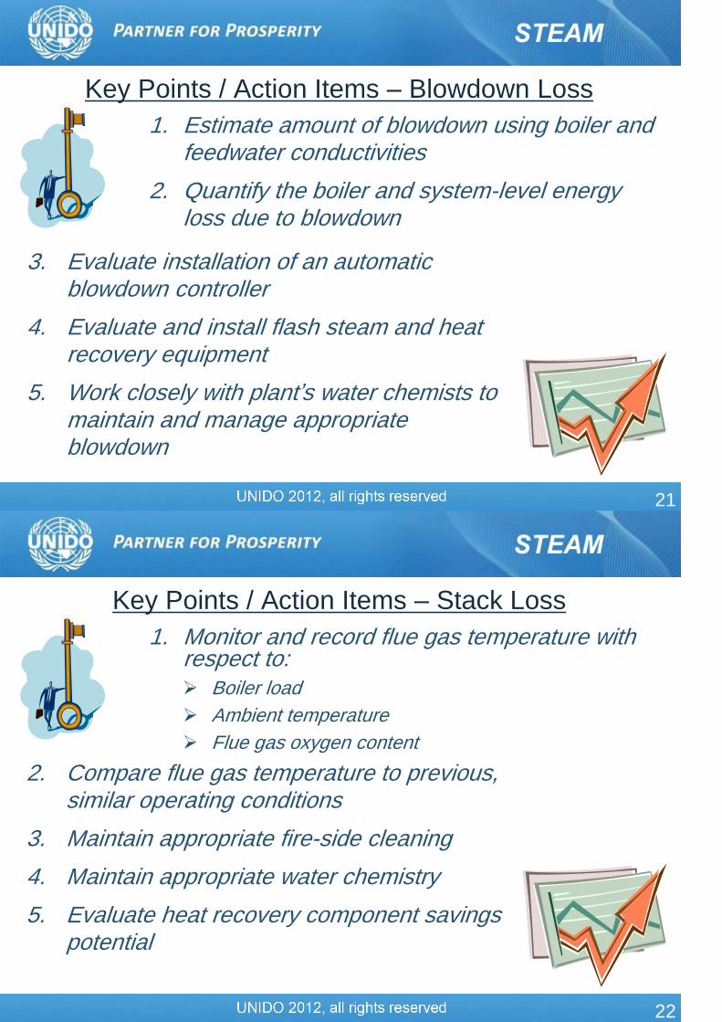
Key Points / Action Items – Blowdown Loss
1. Estimate amount of blowdown using boiler and feedwater conductivities
2. Quantify the boiler and system-level energy loss due to blowdown
3. Evaluate installation of an automatic blowdown controller
4. Evaluate and install flash steam and heat recovery equipment
5. Work closely with plant’s water chemists to maintain and manage appropriate blowdown
22
Key Points / Action Items – Stack Loss
1. Monitor and record flue gas temperature with respect to: Boiler load
Ambient temperature
Flue gas oxygen content
2. Compare flue gas temperature to previous, similar operating conditions
3. Maintain appropriate fire-side cleaning
4. Maintain appropriate water chemistry
5. Evaluate heat recovery component savings potential
23
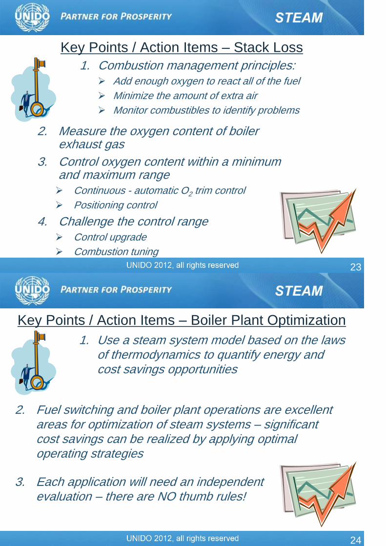
Key Points / Action Items – Stack Loss
1. Combustion management principles: Add enough oxygen to react all of the fuel
Minimize the amount of extra air
Monitor combustibles to identify problems
2. Measure the oxygen content of boiler exhaust gas
3. Control oxygen content within a minimum and maximum range Continuous - automatic O2 trim control
Positioning control
4. Challenge the control range Control upgrade
Combustion tuning
24
Key Points / Action Items – Boiler Plant Optimization
1. Use a steam system model based on the laws of thermodynamics to quantify energy and cost savings opportunities
2. Fuel switching and boiler plant operations are excellent areas for optimization of steam systems – significant cost savings can be realized by applying optimal operating strategies
3. Each application will need an independent evaluation – there are NO thumb rules!

25
Common BestPractices - Distribution
Repair steam leaks
Minimize vented steam
Ensure that steam system piping, valves, fittings and vessels
are well insulated
Isolate steam from unused lines
Minimize flows through pressure reducing stations
Reduce pressure drop in headers
Drain condensate from steam headers
Source: US DOE BestPractices Steam System Sourcebook
26
Key Points / Action Items – Leaks
1. Steam leaks occur in all plants and a continuous improvement type steam leak management program should be implemented in industrial plants
2. An “order of magnitude” steam loss estimate can provide enough information to determine if the repair must be made immediately, during a future shutdown, or online

27
Key Points / Action Items - Insulation
1. There are several reasons for damaged or missing insulation
2. These areas result in significant energy losses and a continuous improvement type insulation appraisal (audit) program should be implemented in industrial plants
3. Some basic instruments, heat transfer models and process data are required to quantify the economic impact of missing or damaged insulation
28
Common BestPractices – End-Use
Reduce steam usage by a process
Improving the efficiency of the process
Shifting steam demand to a waste heat source
Reduce the steam pressure needed by process, especially in
cogeneration systems
Upgrade low pressure (or waste) steam to supply process
demands
Process integration leading to overall energy optimization of
the plant
Source: US DOE BestPractices Steam System Sourcebook

29
Key Points / Action Items – End Use
1. There are several end-uses of steam in industrial plants
2. Do a steam end-use balance in an industrial plant and identify the largest steam end-users in a plant
3. Reduce steam end-use by
Improving the efficiency of the process
Shifting steam demand to a waste heat source or lower pressure steam available in the plant
30
Key Points / Action Items – Heat Exchangers
1. Heat exchangers have a 1st Law efficiency of ~100%
2. Heat exchanger InEffectiveness leads to significant system level energy loss
3. Monitor and trend heat exchanger effectiveness by measuring inlet and outlet temperatures and calculating U-values
4. Clean heat exchangers on a periodic basis to minimize fouling build-up
31
Key Points / Action Items – Process/Utility Integration
1. Upgrade low pressure (or waste) steam to supply process demands
2. Several plants need heating and cooling for process
3. Process integration can lead to significant energy savings opportunities and plant optimization
4. These opportunities will need significantly higher amounts of due-diligence
32
Source: US DOE BestPractices Steam System Sourcebook
Common BestPractices - Recovery
Implement an effective steam-trap management and maintenance program
Recover as much as possible of available condensate
Recover condensate at the highest possible thermal energy
Flash high-pressure condensate to make low-pressure steam

33
Key Points / Action Items – Steam Traps
1. There are different kinds of steam traps and hence, functionality and principles of operation must be understood
2. Major steam trap failure modes - open / closed
3. An effective steam trap management program must be in place
4. There are several commercially available tools for steam trap investigations
5. Conduct a steam trap audit at least once a year and repair/replace defective traps
6. Steam trap manufacturers are a valuable resource
34
Key Points / Action Items – Condensate Recovery
1. Returning condensate
Reduces energy
Reduces make-up water
Reduces chemicals for water treatment
Reduces quenching water
May reduce blowdown
2. Condensate recovery is often neglected but it can provide significant energy savings
3. Quantify the amount of condensate being recovered in a plant using a simple mass balance on the entire steam system
4. Identify potential areas of condensate recovery

35
Common BestPractices – Cogeneration
Process and utility integration leads to overall energy
optimization of the plant
Install backpressure turbines in parallel with pressure
letdown stations and minimize flow through letdown stations
Evaluate backpressure turbine applications for direct
mechanical drives
Evaluate condensing turbines and optimize their operations
to maintain design conditions
Condensing turbines can serve as a system balance
mechanism especially, in industries which have significant
waste heat steam generation
Source: US DOE BestPractices Steam System Sourcebook
36
Key Points / Action Items – Backpressure Turbines
1. Backpressure turbines are used instead of pressure letdown stations
2. Turbine efficiency is NOT 1st law efficiency but a comparison of actual turbine versus an ideal turbine
3. Continuous operations with a simultaneous thermal and electric demand are good candidates for backpressure turbines
4. Each facility analysis is unique and will depend on several economic as well as operating factors
5. Turbine analysis will need a solid thermodynamic steam system model

37
Key Points / Action Items – Condensing Turbines
1. Condensing turbines are used strictly for power generation or driving large mechanical equipment
2. They serve niche applications in the industry
3. Condensing turbines provide maximum shaft power per unit of steam flow
4. Each facility analysis is unique and will depend on several economic as well as operating factors
5. Turbine analysis will need a solid thermodynamic steam system model
38
Personal Goals
Any major issues or concerns as regards the course
material, timeline, etc.
Identification of possible areas which need more in-depth
coverage based on the interests of the attendees
Questions or Discussions from the 2-Day User Training
Specific topics
US DOE Steam BestPractices Tools Suite

39
Industrial Steam System Energy
Assessment
40
Industrial Energy Assessment There are several levels of industrial plant energy assessments
(audits)
• Overall plant-wide
• System focused – steam, compressed air…..
• 1-day, 3-day……
But the overall goal is typically, focused on reductions in energy usage (and/or intensity)
Identification of energy savings opportunities and path to implementation
Expectations vary significantly between plant personnel and energy auditor
41
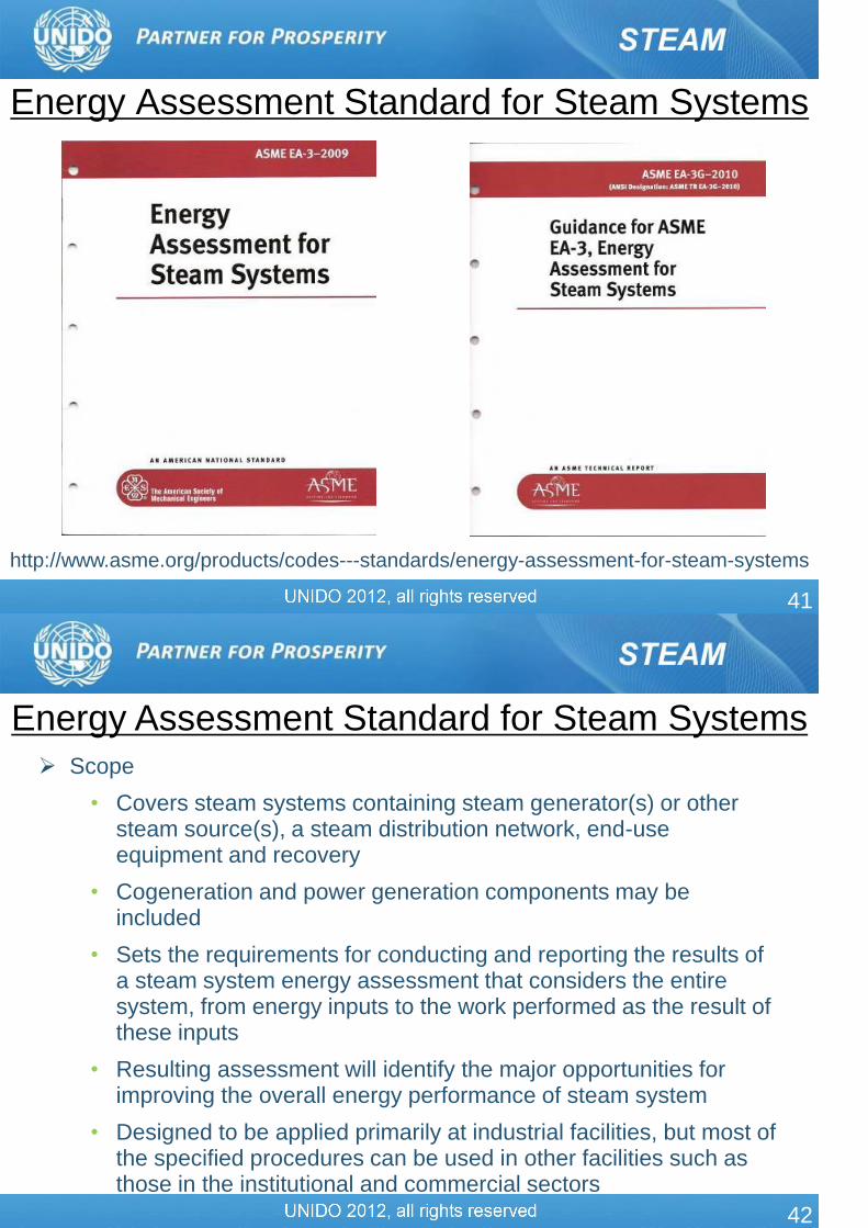
Energy Assessment Standard for Steam Systems
http://www.asme.org/products/codes---standards/energy-assessment-for-steam-systems
42
Scope
• Covers steam systems containing steam generator(s) or other steam source(s), a steam distribution network, end-use equipment and recovery
• Cogeneration and power generation components may be included
• Sets the requirements for conducting and reporting the results of a steam system energy assessment that considers the entire system, from energy inputs to the work performed as the result of these inputs
• Resulting assessment will identify the major opportunities for improving the overall energy performance of steam system
• Designed to be applied primarily at industrial facilities, but most of the specified procedures can be used in other facilities such as those in the institutional and commercial sectors
Energy Assessment Standard for Steam Systems
43
Use of this Standard and accompanying Guidance Document should
increase the quantity and quality of energy assessments performed,
with significant potential savings in implemented energy costs
Intended for energy managers, facility managers, plant engineers,
energy consultants, maintenance managers, plant managers, EH&S
managers, across a broad range of industries
Energy Assessment Standard for Steam Systems
44
The standard clearly identifies the processes, protocols and deliverables of a steam assessment
The sections of the steam assessment standard are:
• Scope & Introduction
• Definitions
• References
• Organizing the Assessment
• Conducting the Assessment
• Assessment Data Analysis
• Report & Documentation
• Appendix A – Key References
An accompanying guide provides more detailed information for each of the sections
Energy Assessment Standard for Steam Systems

45
Typical Project Areas in a Steam System
Assessment
Boiler efficiency improvement
Fuel switching
Boiler blowdown thermal
energy recovery
Steam demand reduction
General turbine operations
Thermal integration
Process/Utility integration
Turbine-PRV operations
Condensing turbine operations
Thermal insulation
Condensate recovery
Flash steam recovery
Steam leaks management
Steam trap management
Waste heat recovery
46
Energy Saving Opportunities
Near-Term Mid-Term Long-Term
Definition
Improvements in operating
and maintenance
practices
Require purchase of
additional equipment and/or
changes
New technology or
confirmation of
performance in plant
Capital ExpenseLow cost actions or
equipment purchases
Rules of thumb estimates
can be made
Additional due-dilligence
required
Payback Less than one year One to to years Two to five years
Examples of
Projects
Boiler combustion
tuning
Insulation
Steam leaks and trap
management
Automatic combustion
control
Blowdown energy
recovery
Feedwater economizer
Combined Heat &
Power
Steam turbine driven
process components
Boiler fuel switching

47
Industrial Steam System Energy
Assessment – Student Exercise
48
Student Exercise Instructions
You have been tasked to undertake a 3-day industrial
steam system energy assessment at a chemicals
manufacturing plant
The plant utilities manager and an energy engineer are
available to work with you all throughout the assessment
and answer any system and process based questions that
you may have
Your goal – Identify and quantify major energy efficiency
improvement opportunities at this plant

49
Student Exercise Instructions
Define the approach that you would take to
Identify current BestPractices at the plant
Develop a list of priority actions to achieve energy efficiency
improvement opportunities and determine areas that require
system level analysis
Complete data collection
Undertake system level analysis for the opportunities that are
identified
Develop summary report & present it to the plant
Future follow up and action items
50
Example Steam System
Indicates a flow meter installation
Boiler Number 1
Coal
Blowdown Purchased
ElectricityBlowdown Blowdown
Process condensate
Makeup water
Turbine condensateDischarge to sewer
Vent
Boiler Number 2
Coal
Boiler Number 3
Natural Gas
Site electrical
demand
HP process
steam demand
51
Student Exercise Steam System Information
The plant (and steam system) operates 24 hours/day, 365 days/year;
There are 3 boilers: two are coal-fired and one is natural gas-fired
The coal-fired boilers are operated continuously and they take care of
the steam demand
The natural gas boiler is operated at minimum fire and serves as a
standby boiler due to its fast response in case one of the coal-fired
boiler trips
Typical average loads correspond to ~70% of total available capacity
Fireside heat transfer surfaces are normally found to be clean
Waterside surfaces have had to be cleaned about every three years
Feedwater economizers exist on the coal-fired boilers
52
Electricity is generated onsite and purchased from a local utility
supplier
Purchased electrical costs are ~$0.08/kWh
Purchased electricity is typically 7 MW
Natural gas is purchased under contract with a price of $0.5/Nm3;
Coal prices are ~$60/tonne
The fuel properties contained in SSAT are appropriate to describe the
fuels
Makeup water is supplied to the facility with a cost of $0.75/m3 and a
temperature of 20°C
Student Exercise Steam System Information

53
The boilers are field erected, water-tube type boilers
The coal fired boilers were the original boilers for the site
The natural gas fired boiler has been recently installed with the
availability of pipeline natural gas
Steam exported from the boilers is significantly superheated
Student Exercise Steam System Information
54
Boiler water treatment data indicates all three boilers operate with
similar water conditions
Deaerator is maintained at 0.3 barg pressure
Feedwater from Deaerator is supplied to Boilers at 25 barg & 110oC
The boilers operate continuously with a boiler water conductivity of
~2,500 µmho/cm
Feedwater conductivity is ~125 µmho/cm
Chlorides measurements of the boiler water typically indicates 280
ppm
Feedwater chloride measurements indicate 14 ppm
Student Exercise Steam System Information

55
The boiler is safety inspected annually by a boiler consultant who
also verifies the operation of the combustion control equipment and
measures efficiency
There are no problems related to wet steam (corrosion, water
hammer), the ability to maintain normal boiler water levels or the
ability to maintain steam pressure to within 1.5 bars of the set-point
Automatic boiler blowdown systems are installed but have not
operated properly recently so blowdown has been adjusted manually
based on once-a-day measurement of boiler water conductivity
Student Exercise Steam System Information
56
High pressure steam is supplied to only one process unit
This process unit utilizes steam in a direct contact process application
This process steam demand is not equipped with a flow meter but the
steam supply to this process is relatively constant
Each of the boilers is equipped with a flow meter indicating steam
production
All the turbines receiving high-pressure steam are equipped with flow
meters
Student Exercise Steam System Information

57
Boiler operations and controls are as follows
• Boiler #1
• Flue gas temperature = 200°C
• Flue gas oxygen = 5% (managed by positional controller)
• Boiler #2
• Flue gas temperature = 230°C
• Flue gas oxygen = 7% (managed by positional controller)
• Boiler #3
• Flue gas temperature = 250°C
• Flue gas oxygen = 4% (managed by automatic trim controller)
Student Exercise Steam System Information
58
Combined boiler steam production - 160 Tph
• Boiler #1 – 70 Tph (20 bars; 300°C)
• Boiler #2 – 70 Tph (20 bars; 300°C)
• Boiler #3 – 20 Tph (20 bars; 300°C)
Medium pressure header – 10 bars
Low pressure header – 2 bars
HP-LP backpressure turbine steam flow – 103.8 Tph
Condensing turbine steam flow - 15 Tph
High pressure to medium pressure PRV flow – 35 Tph
Student Exercise Steam System Information

59
Steam flow meters are in place on the medium-pressure and low-
pressure steam headers
These flow meters record the total steam flow to the process steam
demands
During normal operation steam supply to the medium pressure users
is ~35 Tph
Low pressure process steam demand is ~90 Tph
It has been estimated that one half of the medium and one half of the
low-pressure steam users are connected to the condensate collection
system
Student Exercise Steam System Information
60
The site is equipped with two steam turbines as noted on the system
schematic
HP-LP Backpressure Turbine
• Connected to an electrical generator and which is rated to
produce 5 MW of electric power
• Manages the steam supply into the low-pressure header
• Operates with a load between 65% and 80% of full load
• Receives high pressure steam — boiler outlet conditions
• Discharges steam with a temperature of 214°C and a pressure
of 2 bars
Student Exercise Steam System Information

61
Condensing Turbine Operations
• The steam turbine is connected to an electrical generator
• This component was installed with the original plant construction
when two coal fired boilers served the site
• Steam supply to the turbine is 15 Tph of high pressure steam —
to produce 2.150 MW of electrical output
• The condensing turbine operates with a condensing pressure of
0.15 bara. Assume 1.05 bara as atmospheric pressure
• Generator efficiency is ~95%.
Student Exercise Steam System Information
62
Pressure Reducing Stations
• The steam system is equipped with two pressure reducing
stations
• One operates between the high pressure and the medium
pressure systems
• The other operates between the medium pressure and the low
pressure systems
• These pressure reducing stations are not equipped with
desuperheating stations
Student Exercise Steam System Information
63
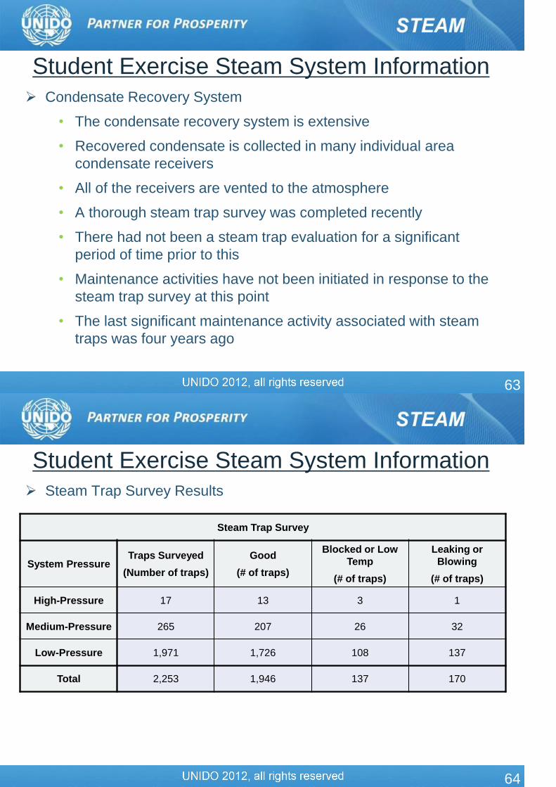
Condensate Recovery System
• The condensate recovery system is extensive
• Recovered condensate is collected in many individual area
condensate receivers
• All of the receivers are vented to the atmosphere
• A thorough steam trap survey was completed recently
• There had not been a steam trap evaluation for a significant
period of time prior to this
• Maintenance activities have not been initiated in response to the
steam trap survey at this point
• The last significant maintenance activity associated with steam
traps was four years ago
Student Exercise Steam System Information
64
Steam Trap Survey Results
Student Exercise Steam System Information
Steam Trap Survey
System PressureTraps Surveyed
(Number of traps)
Good
(# of traps)
Blocked or Low
Temp
(# of traps)
Leaking or
Blowing
(# of traps)
High-Pressure 17 13 3 1
Medium-Pressure 265 207 26 32
Low-Pressure 1,971 1,726 108 137
Total 2,253 1,946 137 170

65
Other system information
• The main condensate receiver for the facility is vented to the
atmosphere
• The vent piping presents a minor (negligible) amount of steam
but this indicates the condensate entering the receiver is
saturated liquid
• Steam leaks appear to be well managed with only very minor
(negligible) leaks observed
• Insulation has been well maintained in the utilities area
• Insulation on the steam distribution and end-use area may
need investigation
Student Exercise Steam System Information
66
Steam System Scoping Tool
• Complete the SSST sections related to “Steam System Operating
Practices” and “Boiler Plant Operating Practices” based on the
information provided
• Also, indicate how you would proceed to obtain any additional
information you would need beyond that provided
• Finally, based on completion of these SSST sections, list the
specific areas on which you would focus your attention to achieve
boiler-related energy savings in the example plant
Student Exercise Questions

67
Boiler #2 Efficiency Calculations
• Estimate the fuel related operating cost of the boiler
• Use only the largest boiler loss to estimate of boiler efficiency
• The calculation should be completed using steam flow, steam
conditions, and an estimate of boiler efficiency
• Estimate the loss associated with boiler blowdown
• Determine the direct and indirect boiler efficiencies
• Assume shell loss is 0.4% of fuel input energy
• Assume LOI loss is 2.1% as provided by laboratory analysis
• Assume a field evaluation has been completed and the
average fuel flow rate is 165 tonne/day
• The fuel higher heating value is 31,890 kJ/kg
Student Exercise Questions
68
Boiler #2 Efficiency Calculations
• Estimate the impact of installation of an automatic oxygen trim
controller
• The controller will reduce the flue gas oxygen content to
4.5% for the general boiler load
• Assume a field evaluation has been completed and the
average fuel flow rate is 165 tonne/day
• The fuel higher heating value is 31,890 kJ/kg
Student Exercise Questions
69
HP-LP Backpressure Turbine Efficiency Calculations
• Determine the isentropic efficiency of the main steam turbine
operating between the high pressure and low pressure
systems
Condensing Turbine Efficiency
• Determine the isentropic efficiency of the condensing turbine
based on the information provided
Student Exercise Questions
70
Steam System Assessment Tool
• Develop the SSAT model that best represents the general
characteristics of the example facility for an evaluation that will
provide representative marginal steam costs
• This model should also provide a good description of the steam
mass balance through the system
• The analyses required for this exercise should be considered
preliminary; as a result do not include boiler shell losses and
LOI (Loss on Ignition)
• Outputs for this exercise are marginal steam costs for the
system and the steam flows through the pressure reducing
valves
Student Exercise Questions

71
Steam System Assessment Tool
• Blowdown Energy Recovery
• Using the SSAT model developed for the general steam
system determine the economic impact of recovering thermal
energy from boiler blowdown
• Present the individual areas of economic impact contributing
to the results
Student Exercise Questions
72
Steam System Assessment Tool
• Condensate Flash Steam Recovery
• Using the SSAT model developed for the general steam
system determine the economic impact of recovering flash
steam produced from the existing condensate recovery
system
• Present the individual areas of economic impact contributing
to the results
Student Exercise Questions
73
Steam System Assessment Tool
• Steam Demand
• Process water was being unnecessarily heated from 40°C to
70°C with low-pressure steam (density 0.992 kg/lit & sp. heat
4.182 kJ/kg/oC)
• The steam trap serving the heat exchanger is functioning
properly and is discharging saturated liquid
• Steam entering the heat exchanger is from the low pressure
system at saturated conditions—heat transfer losses in this
branch line account for the energy loss from the superheated
supply condition
• The process water has a flow rate of ~400 l/min
• Determine the steam system operational cost impact of
eliminating this steam demand
Student Exercise Questions
74
Steam System Assessment Tool
• Steam Turbine versus Electric Motor
• Determine the economic impact of replacing a 100 kW
process drive electric motor with a steam turbine
• Assume the process turbine will operate continuously
between the high-pressure and medium-pressure systems
• The turbine will have an isentropic efficiency of 35%
Student Exercise Questions

75
Steam System Assessment Tool
• 3E Plus Piping Insulation Problem
• One of the process units is supplied medium-pressure steam
through a 150 mm nominal diameter header
• A 20 m long section of the header was observed to be un-
insulated—the result of a past maintenance activity
• The rest of the piping system is covered with a 50 mm thick
calcium silicate insulation and aluminum jacket
• Ambient conditions are typical for an industrial facility
• The piping is located outside on a pipe bridge
• Determine the energy loss reduction and economic impact
associated with replacing the missing insulation
Student Exercise Questions
76
Industrial Steam System Energy
Assessment Report

77
Example – US DOE Steam
Energy Assessment Report
General Information about the
plant
• Industry type
• Size
• Location
• Plant personnel
• Energy Expert, etc.
Energy Assessment Report
78
Basic Plant Information

79
Energy Saving Opportunities
Assessment Opportunities Estimated Annual SavingsSimple
payback
(years)ESO#Recommended
OpportunitieskWh kW GJ
CO2
(Metric
Tons)
Cost
Savings
($)
1
2
3
4
Summary of energy saving opportunities
80
Qualitative recommendations should capture
• Opportunities that were NOT evaluated during the assessment
and the plant is a good candidate for them
• Areas which may NOT directly lend to quantification of energy
savings by implementing them
Qualitative Recommendations
1. Continue with the steam trap management program
2. Increase condensate return to the conservation area
3. Reduce the amount of steam to flares
4. Reduce the amount of steam to equalization tank
5. Combined Heat and Power (CHP) installation
6. Steam system optimization
7. Calibration of instruments
8. Portable instruments to be used by lead
9. Continue monitoring and trending equipment efficiency

81
Observed Best
Practices in the plant
should be highlighted
These should be
encouraged by the
Energy Expert
These are Winners
that the plant needs to
be congratulated for
Observed Best Practices
82
Each Energy Saving Opportunity
should be described in detail:
• Background
• Exact Recommendation
• Estimated Savings
• Methodology for Calculations
of Savings
• Implementation Cost
• Methodology for Calculations
of Implementation Cost
• Next steps towards
implementation
Energy Saving Opportunity
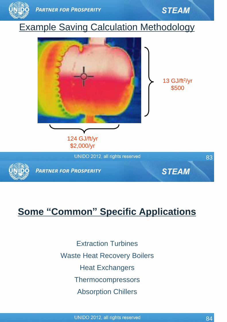
83
13 GJ/ft2/yr
$500
124 GJ/ft/yr
$2,000/yr
Example Saving Calculation Methodology
84
Some “Common” Specific Applications
Extraction Turbines
Waste Heat Recovery Boilers
Heat Exchangers
Thermocompressors
Absorption Chillers

85
Extraction Steam Turbines
Extraction turbines require special attention in SSAT models
Extraction Turbine
Extraction flow
86
Extraction Steam Turbines
A simple approach can result in a robust representation of the system
but slight thermodynamic changes
Extraction Turbine
High-pressure Steam
Medium-pressure Steam
Low-pressure Steam
SSAT Model Arrangement

87
Extraction Steam Turbines
Extraction Turbine
Low-pressure
Steam
SSAT Model Arrangement
High-pressure Steam
Medium-
pressure Steam
Neither of the two techniques is perfect
• HP-MP coupled with MP-LP compromises the steam condition entering the MP-LP turbine
• HP-MP coupled with HP-LP requires judicious flow management
• More accurate method from a thermodynamic standpoint
88
Extraction-Condensing Steam Turbines
Extraction Turbine SSAT Model Arrangement
High-pressure Steam
Extraction Steam
Condenser

89
Waste Heat Recovery Boilers
Waste Heat Recovery (WHR) boilers can take several forms
depending on the source of waste heat
• Heat Recovery Steam Generators (HRSGs) on exhaust of
combustion turbines
• Exothermic reaction in a process
• Heat of combustion of burning waste liquids, etc. in an incinerator
• Recovery of chemicals
• Stack loss from a process heater, furnace, etc.
In most cases, WHR boilers are NOT Impact boilers
In several cases, WHR boilers may be generating steam at a medium
or lower pressure
90
Waste Heat Recovery Boilers
The main questions that need to be answered in an analysis with WHR
boilers
• Can more steam be produced from the WHR boilers?
• If yes, then is the steam system still balanced from a demand and
supply perspective?
• Can steam produced from the WHR boiler offset steam produced
from a fuel-fired boiler?
From a modeling perspective, WHR boilers are best handled by
Project 1 – Steam demand savings, if there is a fuel-fired impact boiler
in the plant whose load can be reduced due to the steam produced by
the WHR boiler

91
Heat Exchanger Operation
T
P
Process HX
Steam
Trap
Bypass
Valve
Control
Valve
92
Heat Exchanger Performance
0
20
40
60
80
100
120
0 0.2 0.4 0.6 0.8 1
HX Length
Tem
pera
ture
(°C
)
Steam / Condensate
Water / Feed
93
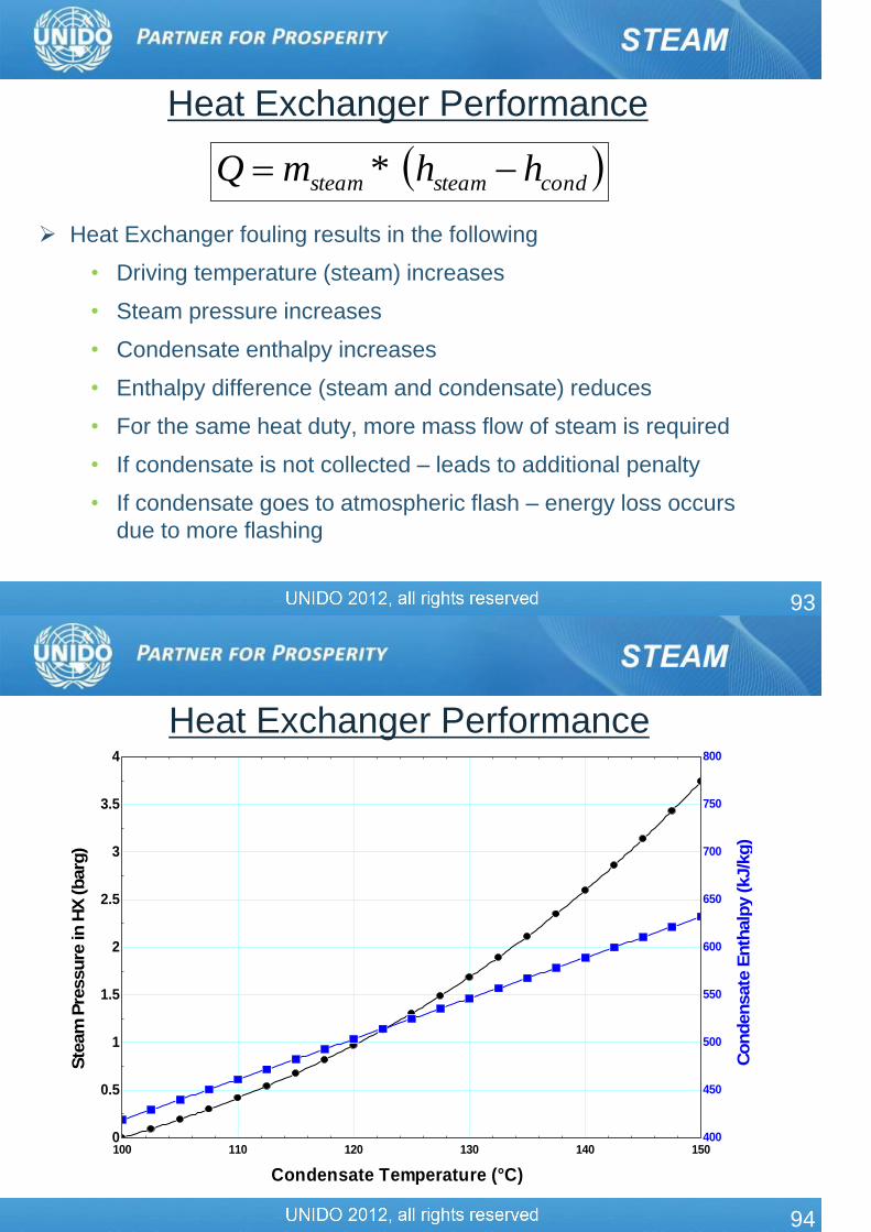
Heat Exchanger Performance
Heat Exchanger fouling results in the following
• Driving temperature (steam) increases
• Steam pressure increases
• Condensate enthalpy increases
• Enthalpy difference (steam and condensate) reduces
• For the same heat duty, more mass flow of steam is required
• If condensate is not collected – leads to additional penalty
• If condensate goes to atmospheric flash – energy loss occurs
due to more flashing
condsteamsteam hhmQ *
94
Heat Exchanger Performance
100 110 120 130 140 1500
0.5
1
1.5
2
2.5
3
3.5
4
400
450
500
550
600
650
700
750
800
Condensate Temperature (°C)
Ste
am
Pre
ssure
in H
X (barg
)
Condensate
Enth
alp
y (kJ/k
g)

95
Heat Exchanger Performance
100 110 120 130 140 1501,500
1,700
1,900
2,100
2,300
2,500
400
480
560
640
720
800
Condensate Temperature (°C)
Ste
am
Enth
alp
y T
ransfe
r in
HX
(kJ/k
g)
Condensate
Enth
alp
y (kJ/k
g)
96
Heat Exchanger Performance
100 110 120 130 140 1501,500
1,700
1,900
2,100
2,300
2,500
1
1.04
1.08
1.12
1.16
1.2
Condensate Temperature (°C)
Ste
am
Enth
alp
y T
ransfe
r in
HX
(kJ/k
g)
Ste
am
Flo
w R
equir
ed v
s. B
ase

97
Thermocompressors Provide the ability to upgrade
low pressure (waste) steam to medium pressure steam thereby reducing the amount of high pressure steam required
Mechanical vapor compression can also be an alternate option for thermocompressor applications
1
2
3
1
2
3
98
Evaporators & Use of Thermocompressors
Jim Munch, JMPS
Typical – 3 Effect
With Thermocompressor
99
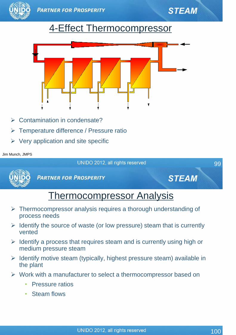
4-Effect Thermocompressor
Jim Munch, JMPS
Contamination in condensate?
Temperature difference / Pressure ratio
Very application and site specific
100
Thermocompressor Analysis
Thermocompressor analysis requires a thorough understanding of process needs
Identify the source of waste (or low pressure) steam that is currently vented
Identify a process that requires steam and is currently using high or medium pressure steam
Identify motive steam (typically, highest pressure steam) available in the plant
Work with a manufacturer to select a thermocompressor based on
• Pressure ratios
• Steam flows

101
Absorption Chillers
Condenser
SubCooler
Receiver
Compressor
Evaporator
HGBP
HGBP
Cooling Water
Cooling Water Chilled Water
102
Absorption Chillers
Condenser
SubCooler
Receiver
Th
erm
al C
om
presso
r
Evaporator
Cooling Water
Cooling Water Chilled Water
Absorber Cooling Water
Generator Heat Input

103
Condensing Economizers
104
Case Study – Refinery 1 Optimize Operations between Steam Turbines and Electric Motors to
minimize steam system losses
Current configuration
• Steam let down from HP to MP header is 18,850 tonnes
• Steam letdown MP to LP header was 110,368 tonnes in 1996
• Steam venting from LP steam header was 11,108 tonnes
Action needed
• Determine operating costs of all steam turbines & stand-by motor drives
• Consider operation at different energy cost & steam balance scenarios
• Decide a priority list of switch-over between motors & turbines

105
MP Steam line
Excess LP steam
condenser
LP Steam line
Condensate
collection
tank
HP Steam line
Condensate header
LP steam
consumers
MP steam consumers
HP steam consumers
Rotating equipment that have
both Motor & Turbine drives
M
M
MT T
T
RE RE
RE
BOILERS
Case Study – Refinery 1
106
Total
available
turbines
Turbines
normally
in service
Normal steam
consumption
(Kg/hr)(T/hr per
turbine)
HP steam turbines
C2 refrig compressor turbines 3 2 23,830 11.91
Air compressor turbines 2 1 7,207 7.21
Boiler feed pump turbines 3 3 16,847 5.62
Stabilizer reboiler turbines 14 12 64,924 5.41
Stabilizer inter-heater pumps # 1 – 4 4 4 15,480 3.87
Cooling water pump turbine (MP) 2 2 16,757 8.38
Stabilizer inter heater pumps # 5 – 7 (MP) 3 2 18,257 9.13
Stabilizer O.H. compressor turbine (C) 2 2 31,932 15.97
MP steam turbines
Condensate to Deaerator pumps 2 2 3,243 1.62
C3 vaporizing Glycol pump 1 1 1,340 1.34
C2 stablg. Compr. Sealoil turbine 3 2 2,532 1.27
Treated water pumps 2 1 1,025 1.02

107
Switch-Over between turbines & motors to optimize steam
system losses
STEAM
TURBINE
ELECTRIC
MOTOR
Ethane
Refrigeration
Compressor
12 t/hr HP
steam
LP steam
12 t/hr
1155 kwh
@ 84.84 $/hr
@ 72.24 /hr
@ 46.2 $/hr
84.84
12.6
46.2
0
20
40
60
80
100
Turbine Turbine Motorwhen LP steam is
fully consumed
when LP steam
is vented
Loss in operating
turbine when LP
steam is ventedLoss in operating Motor
when LP steam is
letdown through PRV
72.24 /hr
33.6 /hr
$/hr
108
MP Steam line
LP Steam line
Condensate
collection
tank
HP Steam line
LP steam consumers
MP steam consumers
HP steam consumers
Turbine
BOILERS
Alternator
.
109
Case Study – Refinery 1 Conclusions
• Refinery’s Steam system has the flexibility to achieve Optimized
Steam Balance. It was recommended to take advantage of this
flexibility.
• A priority list of switch-over between electric motors & steam
turbines was developed
Estimated Benefits
• Optimizing steam balance at the refinery will save $30,000
annually
110
Case Study – Fertilizer Plant
Current Configuration
• A single shaft machine at a Nitric Acid plant has 3-Turbine drives,
2-process compressors and a Turbo Alternator to generate
electricity
• The 2nd Turbine drive was driven with LP steam, obtained from
the exhaust steam of the 1st HP turbine
• To generate additional power, LP steam from other sources also
was routed to this 2nd LP turbine
• To match with the LP steam temperature from other sources, the
turbine exhaust steam was de-superheated by spraying BF water

111
PRV 764/1
Generator
LP turbine
J-101 E HP turbine
J-101 D
Air
Compressor
J-101 A
Tail Gas
Expander
J-101 C
NOx
Compressor
J-101 B
Gear
Box
Desuperheater
Steam 55 T/hr
@ 64 barg 500oC
Steam
20 barg
@370oC
55 T/hr
Steam @20 barg & 287oC, 70T/hr
Steam
125 T/hr
20 barg
@301oC
Steam @315oC
B. F. Water
15.7 MW
L 155
Steam @ 5 barg
Condenser
C-101
C.W in @27oC
C.W out @17oC
Current Configuration
112
Observed Deficiency
• Since Steam turbines achieve better performance with superheated steam, the existing practice of de-superheating unnecessarily reduces the Turbo Alternator’s power generation potential
• Upon verification, the turbine metallurgy could withstand the additional temperature of the superheated steam supply
Recommended Action
• It was recommended to stop de-superheating of the exhaust steam from the HP turbine, to generate 500kW of additional electricity
Case Study – Fertilizer Plant

113
PRV 764/1
Generator
LP turbine
J-101 E HP turbine
J-101 D
Air
Compressor
J-101 A
Tail Gas
Expander
J-101 C
NOx
Compressor
J-101 B
Gear
BoxDesuperheater
by-passed
Steam 55 T/hr
@ 64 barg 500oC
Steam
20 barg
@370oC
55 T/hr
Steam @20 barg & 287oC, 70T/hr
Steam
125 T/hr
20 barg
@328oC
Steam @370oC
B. F. Water
15.7 MW+0.5 MW
L 155
Steam @ 5 barg
Condenser
C-101
C.W in @27oC
C.W out @17oCProposed
modifications
LEGEND
Modified Configuration
Estimated Benefits: Annual purchased electricity cost reduction ~$300,000
114
STEAM SYSTEM AT THE HOST PLANT
Host Plant : TABRIZ Oil Refinery (TZ.O.R.C.)
Total Actual Steam Production:
• ca. 300 t/h HP steam by 4 of 5 Boilers (A, B, C, D, E)
• ca. 80 t/h HP steam by 2 HRSG’s (supplied by GT’s)
Major Steam Supply to (the 7 biggest consumers) :
• Condensing Steam Turbines at Utility
• CDU Unit (Crude Distillation Unit)
• CCR Unit (Catalytic Cracking & Reforming Unit)
• Isomax Unit
• Letdowns
• Cooling Pumps
• Feed Pump

115
STEAM SYSTEM AT THE HOST PLANT
Pilot Site Investigations & Possible Pilot Projects
1. Steam Boilers Performance Investigation
• Performance seems to be too low (as reported) –
Boilers run at max. 85 t/h, but per design ca. 100 t/h possible.
(Note present design: combustion air controlled by flue gas oxygen content)
Target: Energy saving by shut down of one boiler. Possible ?
(Note: One unit, either A, B, C or D in standby, while E is always operating).
Measurements, Observations:
gas analyser to install (O2 check, also investigate on NOX).
visual inspection of burners,
visual inspection with thermovision camera on boilers,
conductivity (TDS) data (boiler feedw. & blowdown from control room)
116
STEAM SYSTEM AT THE HOST PLANT
Pilot Site Investigations & Possible Pilot Projects
2. Steam Boilers Stack Temperature Investigation
• Stack temperature after economizer actually around 200°C far too high
for efficient steam generation.
(But site personnel argue that with reducing the temperature there would be
condensate in stack to result in stack corrosion. Note: Stack design – long and of
high diameter could be problem, since on chimney top condensation could
happen (especially in winter).
Target: Energy saving by reduction of boiler temperature. Question: How?
Measurements, Observations:
insertion thermocouple (for data comparison),
visual inspection with Thermovision camera on stack.
117
STEAM SYSTEM AT THE HOST PLANT
Pilot Site Investigations & Possible Pilot Projects
3. Steam Turbine Isentropic Efficiency Investigation
• 10 MW Condensing Steam Turbine with Extraction in Utility Unit
Note: 2 identical units on site – measurement on both
Targets: -) Exercise for calculation of isentropic efficiency.
-) Exercise for modelling an extraction turbine in SSAT.
-) Is actual efficiency fine?
Measurements, Observations:
Local field instruments (pressure, temperature) & data from control room
(e.g. extraction heat flow).
118
STEAM SYSTEM AT THE HOST PLANT
Pilot Site Investigations & Possible Pilot Projects
4. Investigate Steam Distribution in CDU Unit
• Steam Traps (failing traps) investigation
• Steam Tracing investigation,
• Leakages & Steam losses (also from failing traps) investigation,
• Insulation investigation.
Targets: -) Learn to check if steam traps function or not,
-) Energy losses reduction by steam traps monitoring.
-) Energy losses reduction by decreasing number of leakages, steam
losses & insulation failures.
Measurements, Observations:
Ultrasonic steam detector,
Thermovision camera.

119
STEAM SYSTEM AT THE HOST PLANT
Pilot Site Investigations & Possible Pilot Projects
5. Investigate Steam Distribution & Losses in CCR Unit
a. Steam Venting at Booster Compressors (gland steam seal vent on 4 steam
turbine units)
b. The “LLP Steam Problem“ & heat waste through cooling the condensate
Targets: -) Potential Energy Recovery by using vent steam.
-) Reduce LLP steam amount
-) Eliminate heat losses from condensate cooling.
Measurements, Observations:
Thermovision camera.
120
Portable Instrumentation to be used for the steam system energy
assessment
• Infra-red thermographic camera
• Combustion flue-gas analyzer
• IR temperature guns
• Thermometers with k-type probes
• Pitot tube with digital manometer
• Pressure gages
• Digital camera
• Stop watch
Industrial Steam System Assessment

121
Other Tools & Resources
122
Tools
In order to properly evaluate steam systems the physics of each process must be understood
• Thermodynamics
• Heat transfer
• Fluid flow
US DOE Tools Suite
• Steam System Survey Guide
• Steam System Scoping Tool (SSST)
• Steam System Assessment Tool (SSAT)
• Insulation evaluation software – 3E-Plus
Several other commercially available software tools for steam systems
Process measurements

123
Where to Download the Tools
US DOE website -http://www1.eere.energy.gov/industry/bestpractices/software.html
124
Technical Publications & Resources
http://www1.eere.energy.gov/industry/bestpractices/publications.asp
125
Steam System Survey Guide
Technical Guide
Covers 5 Areas:
• Steam system profiling
• Identifying steam properties
• Improving boiler operations
• Improving resource utilization
• Improving steam distribution
126
Steam System Sourcebook Includes Three Main Sections:
• Steam System Basics
• Performance Improvement
Opportunities
• Programs, Contacts, and
Resources
127
Steam Energy Tips
1- Page Tips For Improving Steam
System Areas
Available On BestPractices Web
Site and in Steam Sourcebook
128
US DOE Tip Sheets Benchmark the Fuel Cost of Steam Generation
Clean Boiler Water-side Heat Transfer Surfaces
Consider Installing a Condensing Economizer
Consider Installing High-Pressure Boilers with Backpressure Turbine-Generators
Consider Installing Turbulators on Two- and Three-Pass Firetube Boilers
Consider Steam Turbine Drives for Rotating Equipment
Considerations When Selecting a Condensing Economizer
Cover Heated, Open Vessels
Deaerators in Industrial Steam Systems
Flash High-Pressure Condensate to Regenerate Low-Pressure Steam
Inspect and Repair Steam Traps
Install an Automatic Blowdown Control System
Install Removable Insulation on Valves and Fittings
Insulate Steam Distribution and Condensate Return Lines

129
US DOE Tip Sheets Improve Your Boiler's Combustion Efficiency
Minimize Boiler Blowdown
Minimize Boiler Short Cycling Losses
Recover Heat from Boiler Blowdown
Replace Pressure-Reducing Valves with Backpressure Turbogenerators
Return Condensate to the Boiler
Upgrade Boilers with Energy-Efficient Burners
Use Feedwater Economizers for Waste Heat Recovery
Use Low Grade Waste Steam to Power Absorption Chillers
Use Steam Jet Ejectors or Thermocompressors to Reduce Venting of Low-Pressure Steam
Use Vapor Recompression to Recover Low-Pressure Waste Steam
Use a Vent Condenser to Recover Flash Steam Energy
130
US DOE Technical Documents Improving Steam System Performance: A Sourcebook for Industry
Achieve Steam System Excellence: Industrial Technologies Program BestPractices Steam Overview Fact Sheet
BestPractices Steam Technical Brief: Steam Pressure Reduction-Opportunities and Issues
BestPractices Steam Technical Brief: How to Calculate the True Cost of Steam
BestPractices Steam Technical Brief: Industrial Heat Pumps for Steam and Fuel Savings
BestPractices Steam Technical Brief: Industrial Steam System Heat-Transfer Solutions
131
US DOE Technical Documents BestPractices Steam Technical Brief: Industrial Steam System
Process-Control Schemes
Guide to Combined Heat and Power Systems for Boiler Owners and Operators
Guide to Low-Emission Boiler and Combustion Equipment Selection
Review of Orifice Plate Steam Traps
Save Energy Now in Your Steam Systems
Steam Digest: Volume IV (2003)
Steam Digest 2002
Steam Digest 2001
Steam Systems Energy Efficiency Handbook
Steam Systems Survey Guide