industry consultation paperassets.highways.gov.uk/specialist-information/guidance... · web...
TRANSCRIPT
_____________________________________________________________________
Inter-Urban Traffic Management & Control
Industry Consultation Paper
iUTMC Specification RFC/RFI Page 1 of 58 Author: Mike Williams Date: 28/06/11 Version 1.3
_____________________________________________________________________
CONTENTS
CONTENTS 2
FORWARD 5
1. INTRODUCTION 6
1.1. Background 6
1.2. Why is an iUTMC Specification required? 6
1.3. Purpose of this document 6
1.4. Industry Responses 6
2. THE NEED FOR A DATA-CENTRIC APPROACH 7
2.1. Capability Models 7
2.2. Road Network Operator Capabilities 7
2.3. HA Information Strategy 9
2.4. Service-Orientation 10
2.5. The HA’s ITS Metadata Registry 11
2.6. Datex II 12
2.7. Data Exchange 13
3. HETEROGENEOUS SYSTEMS 17
3.1. Overview 17
3.2. Communication Channels 183.2.1. Voice 183.2.2. Data 183.2.3. Video and Still Image 193.2.4. Text 193.2.5. In-Car 20
3.2.5.1. Digital Radio 203.2.5.2. RDS and RDS-TMC 203.2.5.3. Future developments - CVHS 20
3.2.6. Roadside 21
iUTMC Specification RFC/RFI Page 2 of 58 Author: Mike Williams Date: 28/06/11 Version 1.3
_____________________________________________________________________
3.2.6.1. Video and Still Image 213.2.6.2. Traffic Sensor Data/Telemetry 21
3.2.6.2.1. Inductive Loops 213.2.6.2.2. Microwave/Radar 213.2.6.2.3. Infrared Detection 213.2.6.2.4. Magnetic Anomaly Detector 223.2.6.2.5. Fibre Optic Detectors 223.2.6.2.6. Acoustic Detection 22
3.2.6.3. Weather Sensor Data/Telemetry 223.2.6.4. Signals 23
3.2.6.4.1. Ramp Metering 233.2.6.4.2. Central Reserve Post-mounted Signals (Matrix Signals) 233.2.6.4.3. Slip Road Post-mounted Signals 233.2.6.4.4. Gantry Mounted Signals 23
3.2.6.5. Variable Message Signs 243.2.6.5.1. Enhanced Message Sign (EMS) 243.2.6.5.2. Message Sign Mark 2 (MS2) 243.2.6.5.3. Message Sign Mark 3 (MS3) 243.2.6.5.4. Advanced Message Indicator (AMI) 25
3.3. Delivery Interfaces 253.3.1. Internal (HA) Interfaces 27
3.3.1.1. Network 273.3.1.2. Mobile Data 273.3.1.3. Enterprise Service Bus 273.3.1.4. Unified Operator Interface 273.3.1.5. Voice 27
3.3.2. External Interfaces 283.3.3. B2B Gateways 283.3.4. Web Portal 283.3.5. Voice 283.3.6. In-Car 28
3.4. Channel Summary 28
4. CANDIDATE ARCHITECTURE BUILDING BLOCKS 29
4.1. Overview 29
4.2. Data Distribution Service (DDS) 324.2.1. What is DDS? 324.2.2. How is DDS different? 324.2.3. What about Request/Response Support? 334.2.4. What about Developer Support? 344.2.5. What are the benefits of DDS? 354.2.6. Who uses DDS? 364.2.7. Example Scenario 37
4.3. Roadside components and devices 374.3.1. Introduction 374.3.2. SODA – Eclipse Project 394.3.3. SODA – ITEA Project and DPWS 394.3.4. DPWS 414.3.5. Component Models and Protocol Bindings 424.3.6. Embedded Java and OSGi 44
iUTMC Specification RFC/RFI Page 3 of 58 Author: Mike Williams Date: 28/06/11 Version 1.3

_____________________________________________________________________
4.3.7. Device Management 464.3.7.1. Introduction 464.3.7.2. Management Platforms and SNMP 474.3.7.3. Web Based Configuration 484.3.7.4. OSGI Remote Component Management 48
5. REQUEST FOR COMMENTS AND INFORMATION 50
ANNEX A – QUESTIONNAIRE 51
Data Distribution Service (DDS) 51
Service-Oriented Device Architectures 51
ANNEX B – CIO MEMO 02/09 54
ANNEX C – DEVELOPING A DATA EXCHANGE ARCHITECTURE 55
Annex D – Glossary 56
Revision History
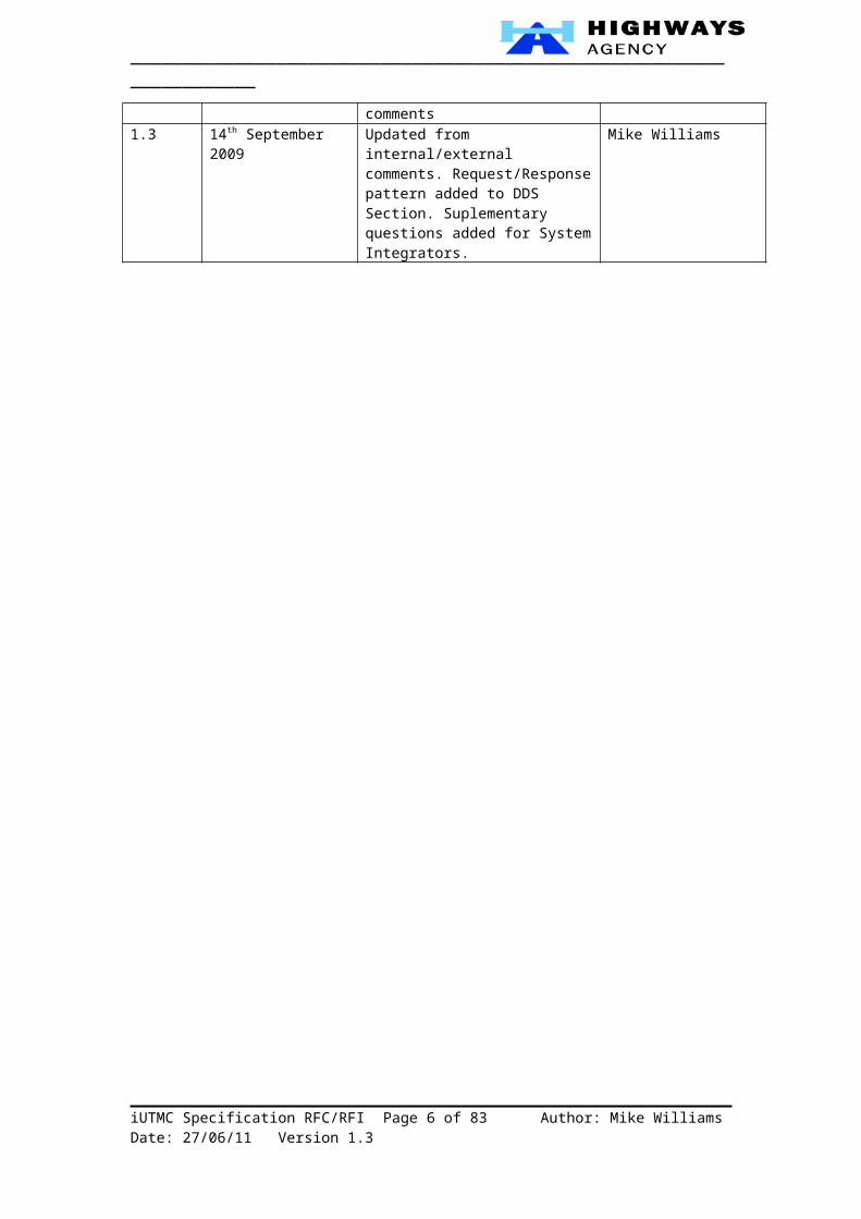
Version Date Description Author1.0 18th July 2009 First issue Mike Williams1.1 26th July 2009 Datex II section updated. Mike Williams1.2 12th August 2009 Updated from internal comments Mike Williams1.3 14th September 2009 Updated from internal/external
comments. Request/Response pattern added to DDS Section. Suplementary questions added for System Integrators.
Mike Williams
iUTMC Specification RFC/RFI Page 4 of 58 Author: Mike Williams Date: 28/06/11 Version 1.3

_____________________________________________________________________
Forward
Currently the Highways Agency spends in excess of £1/3 Billion per annum on Information and Communications Technology (ICT), including both Operational and Business Support Services (OSS/BSS).
Studies have shown that by making a minimum of 10-15% investment in strategic planning and control this can deliver a dramatic reduction in programme risk and costs resulting in a higher Return on Investment (RoI).
Our strategic vision is simply - “The right information in the right place at the right time to inform decision making”.
Our key objectives for improved ICT strategic planning and control are:
To support collaboration across the enterprise and provide "one version of the truth" leading to a more integrated network operator capability.
To control complexity and improve ROI by improving efficiency whilst reducing the time, cost and risk of transformation.
To facilitate a more customer-centric enterprise where Control Room operators focus on managing incidents and the resulting traffic congestion rather than operating technology.
To increase our adaptability and agility.
To simplify and speed up integration with operational partners.
By issuing this consultation paper, I invite you all to join with us in making our vision a reality.
Ivan Wells, C.Eng, BSc(Hons), MIETEnterprise Architecture Team LeaderInformation Strategy and ArchitectureHighways Agency
iUTMC Specification RFC/RFI Page 5 of 58 Author: Mike Williams Date: 28/06/11 Version 1.3
_____________________________________________________________________
1 Introduction
2 Background
The Highways Agency’s Enterprise Architecture Team has begun publishing Technology Policies and Standards in support of the Agency’s business and technology capabilities. In doing so, it is recognised that there is a need for these policies and standards to be discussed, challenged, agreed and progressively improved over time. As such, the Agency and the ITS industry stands to benefit from establishing a consensus of best practice and convergence in this field. To this end, the Agency opened a consultation period that ran until the end of July 2009. As part of this process the HA invited anyone concerned to look at the published policies and standards and to comment on their accuracy and suitability for supporting the Agency’s business. CIO Memo 02/09 refers and gives further details – a copy is included at Annex B.
This industry consultation document (Green Paper) extends this consultation process in order to specifically explore some policy options in the field of Inter-Urban Traffic Management and Control (iUTMC). Amongst other things, this is required to support the migration towards a Service-Oriented Architecture (SOA) based on open and international standards.
3 Why is an iUTMC Specification required?
Historically, the Agency has produced its own proprietary specifications for Traffic Systems & Signing (TSS). However, in the current climate of Intelligent Transport Systems (ITS) there is a need, going forward, to adopt open and international standards which are in line with UK Government policies and relevant EU Directives and Action Plans. The problem with standards though is that there are lots to choose from and having too many standards is almost as problematic as not having any at all.
The Agency’s aim is to develop a technical framework which not only meets its own internal business needs but also dovetails in with a wider national and European framework for ITS.
4 Purpose of this document
The next step in the Enterprise Architecture process is to extend the Technology Policies from the current conceptual and logical levels into the physical level and incorporate these into specifications which will then be used in future procurements. Like the Technology Policies, the Agency’s EA Team wishes to provide the industry with an opportunity for early engagement prior to the issue of these specifications. The purpose of this document, therefore, is to provide such an opportunity. Feedback obtained through this process will then inform the detailed policies and specifications that follow.
5 Industry Responses
The consultation period for the Technology Policies referred to above and in the CIO Memo 02/09 completed on 31st July 2009.
As this consultation document has only been released in late July we are looking for related industry responses by 30th September 2009.
iUTMC Specification RFC/RFI Page 6 of 58 Author: Mike Williams Date: 28/06/11 Version 1.3

_____________________________________________________________________
6 The need for a data-centric approach
7 Capability Models
From the outset, the EA Team has adopted Capability Modelling as a technique which fits in with the OGC’s Managing Successful Programmes (MSP) best practices – “Delivering the New Capability”. This has since become more recognised within the TOGAF 9 Capability Framework. Consequently, the HA’s Business Architecture is defined in these terms.
A “Capability” here is defined as “The practical ability to realise business benefit by a combination of Processes, Organisation, Technology and Information. Capabilities must be measurable over time and are delivered by one or more programmes/projects.”
The Microsoft Motion Business Architecture Methodology describes a generic business capability model as follows in Figure 1 below.
Figure 1 - Foundation capabilities common to most businesses
8 Road Network Operator Capabilities
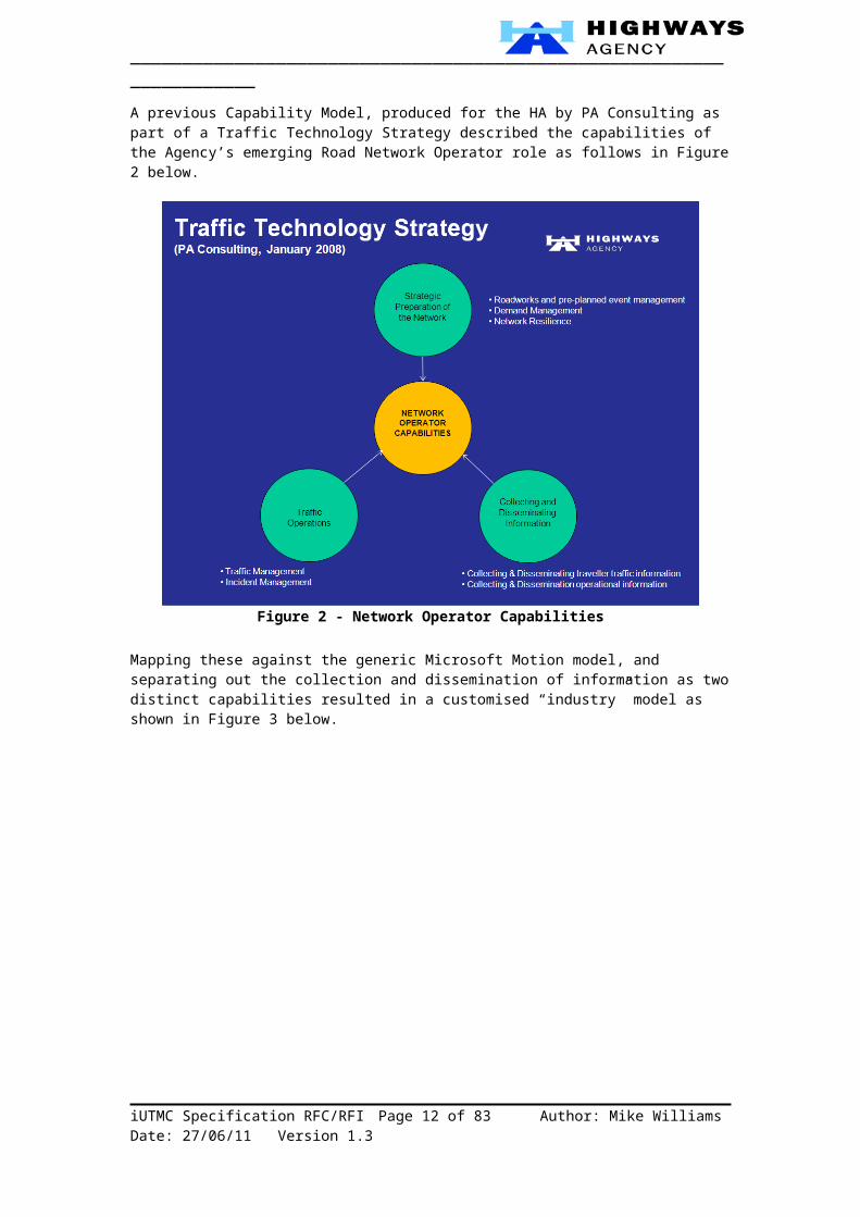
A previous Capability Model, produced for the HA by PA Consulting as part of a Traffic Technology Strategy described the capabilities of the Agency’s emerging Road Network Operator role as follows in Figure 2 below.
iUTMC Specification RFC/RFI Page 7 of 58 Author: Mike Williams Date: 28/06/11 Version 1.3

_____________________________________________________________________
Figure 2 - Network Operator Capabilities
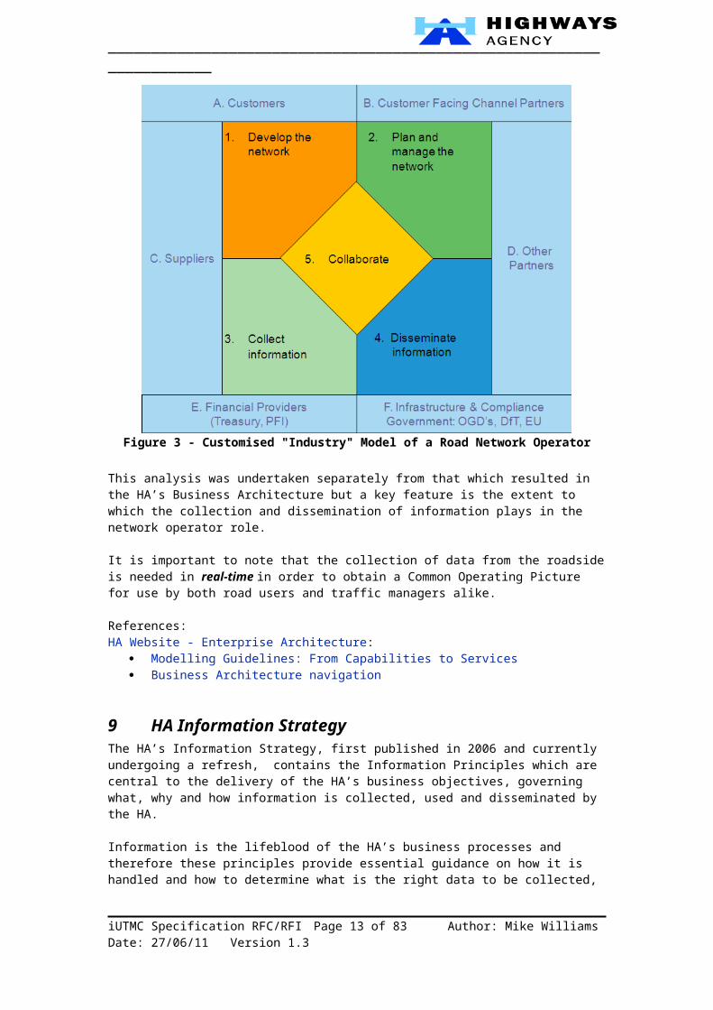
Mapping these against the generic Microsoft Motion model, and separating out the collection and dissemination of information as two distinct capabilities resulted in a customised “industry” model as shown in Figure 3 below.
Figure 3 - Customised "Industry" Model of a Road Network Operator
iUTMC Specification RFC/RFI Page 8 of 58 Author: Mike Williams Date: 28/06/11 Version 1.3
_____________________________________________________________________
This analysis was undertaken separately from that which resulted in the HA’s Business Architecture but a key feature is the extent to which the collection and dissemination of information plays in the network operator role.
It is important to note that the collection of data from the roadside is needed in real-time in order to obtain a Common Operating Picture for use by both road users and traffic managers alike.
References:HA Website - Enterprise Architecture:
Modelling Guidelines: From Capabilities to Services Business Architecture navigation
9 HA Information StrategyThe HA’s Information Strategy, first published in 2006 and currently undergoing a refresh, contains the Information Principles which are central to the delivery of the HA’s business objectives, governing what, why and how information is collected, used and disseminated by the HA.
Information is the lifeblood of the HA’s business processes and therefore these principles provide essential guidance on how it is handled and how to determine what is the right data to be collected, used and disseminated. The quality and availability of the information are also key elements which are addressed by the Information Principles. These are outlined in Table 1 below.
Table 1 - Information PrinciplesNo. IS Principle Explanation of principle1 Understand
what our customers want
“We shall ensure we understand and appreciate how our information is most useful to our customers and stakeholders now, and what they would like in the future. We shall ask them regularly so we do not let our own assumptions and preferences override theirs.”
2 Provide high quality information
“Our information will be designed and presented in ways that encourage and help our customers to use it. Information should be available when and where they want it. We must keep it relevant and up-to-date, and its quality must inspire our customers’ confidence and trust.”
3 Build an effective delivery chain
“By working with our supply chain partners we shall design an information delivery chain that meets our customers’ needs. We shall ensure that it is resilient, reliable and scalable, and able to respond to changes in our customers needs. We shall also avoid duplicating existing information services that are reliable and effective.”
4 Communicate effectively
“We shall address our customers’ and stakeholders’ needs simply and consistently, linking closely with the Agency’s other communications work. To make sure that we get our messages through, our language will focus on being helpful, easy to understand and concise. We shall promote all the places that customers can get our information so that they can take full advantage of them. We shall do the same with our internal information systems so our staff knows what information is available to help them with our drive in putting customers first.”
iUTMC Specification RFC/RFI Page 9 of 58 Author: Mike Williams Date: 28/06/11 Version 1.3

_____________________________________________________________________
5 Future-proof our systems
“We recognise that our world is changing all the time. We shall ensure our information systems respond to developments in government policy and legislation. Our systems will be designed and developed so that they deliver the information our customers want, well into the future.”
6 Collaboration “We can achieve more for our customers by exploiting opportunities for better collaboration. We shall improve the way that we collaborate on information systems and technological developments with our supply chain, our stakeholders and the private sector.”
7 Governance “We shall make sure we improve the way we provide information and information systems by controlling what we do within a clear framework based on proven management principles. We shall be open to scrutiny, encouraging our customers to tell us where we are going wrong and learning methodically from our mistakes. Equally, we shall celebrate success. We shall evaluate the full costs and benefits of everything we do.”
8 Support technological developments
“We shall understand customer preferences for the technologies they use, and influence the development of that technology. In particular, we shall support the development of in-vehicle systems to deliver information safely to our customers.”
References:HA Information Strategy
10 Service-Orientation
The Agency’s policy is to move to a loosely-coupled, service-based modular approach in the design of any new systems, rather than building large monolithic systems that serve only themselves. Service-based modules will allow and encourage their re-use by other services. By re-using modules to provide common services, the HA will immediately begin to gain efficiencies and reduce overall expenditure. This is to be accompanied by a move away from purchasing systems to contracting for Managed Services. This policy has led to an ICT Strategy based on a Service-Oriented Architecture (SOA). In the context of a large-scale SOA deployment which is multi-vendor and heterogeneous in nature, this poses a significant challenge to achieve the necessary loose-coupling between service modules.
This decoupling between service providers and consumers may be decomposed along three dimensions:
1. Space decoupling: the providers and consumers do not need to have any knowledge of each other.
2. Time decoupling: they do not necessarily need to actively participate in the interaction at the same time.
3. Synchronisation decoupling: providers are not blocked from sending because the consumer is busy with some other concurrent activity, i.e. the communication may be asynchronous.
This decoupling may be met through a number of standard communication paradigms:
Message passing, Remote Procedure Call (RPC), Notifications, Shared memory,
iUTMC Specification RFC/RFI Page 10 of 58 Author: Mike Williams Date: 28/06/11 Version 1.3

_____________________________________________________________________
Message queuing Publish-subscribe
The decoupling capabilities of these are evaluated in Table 2 below.
Table 2 - Decoupling CapabilitiesMethod Space Time SynchronisationMessage passing No No Producer-sideRemote Procedure Call (RPC) No No Producer-sideAsynchronous RPC No No YesFuture RPC No No YesNotifications (Observer pattern) No No YesShared memory Yes Yes Producer-sideMessage queuing (Pull) Yes Yes Producer-sidePublish-Subscribe Yes Yes Yes
As can be seen from the above, traditional communication paradigms provide only limited support for time, space and synchronisation decoupling. It is for this reason that the HA is focusing on publish-subscribe as a principal integration pattern for the “To-Be” SOA in the context of Application-to-Application (A2A) and Machine-to-Machine (M2M) communication. Note that this is viewed as being quite separate to traditional Enterprise environments characterised by Request/Response communications and Human-Computer Interfaces (HCI) where client/server models and portals are the dominant architectural patterns.
References:The Many Faces of Publish/Subscribe, ACM Computing Surveys, Vol. 35, No. 2, June 2003, pp. 114–131
11 The HA’s ITS Metadata Registry
The HA’s ITS Metadata Registry is a repository of data definitions and data models, with an associated supporting process for the improvement of quality and for harmonisation across different systems. The registry aims to cut across work in isolated "silos" and avoid re-invention and duplication of effort.
The registry is based on UML (Unified Modelling Language), so it will be best understood by those familiar with UML. However, the individual items generally have plain text descriptions, and are arranged in a simple hierarchy, so the registry should also be fairly communicative to those without detailed UML knowledge. The organisational structure of the registry, and some of the detailed terms, comes from the ISO 14817 standard. Knowledge of this standard is helpful, although much of the knowledge that is required can be found on the ITS Registry web site.
The original intention of the registry project was to use the ISO status level of "Preferred" to provide recommendations for ITS data definitions. However, so far no complete model has achieved "Preferred" status - typically due to missing documentation on classes or attributes.
Instead of relaxing the status levels, an additional concept of "recommended" models was introduced. Models may be "recommended" for particular specified business contexts, with caveats explaining why they have not yet achieved “Preferred” status.
References:www.itsregistry.org.uk
12 Datex II
iUTMC Specification RFC/RFI Page 11 of 58 Author: Mike Williams Date: 28/06/11 Version 1.3
_____________________________________________________________________
DATEX II is a facilitator for the electronic exchange of traffic and travel related data between traffic centres including cross-border exchange. It acts as the “market place” between organisations in the information chain. A set of specifications was developed within an R&D project co-funded by the European Commission.
DATEX II is set to become the Technical Specifications, governed by the CEN Technical Committee 278 (Road Transport and Traffic Telematics). The first three standards, dealing with the most mature and widely used parts of DATEX II are:
1. The modelling methodology.2. Location Referencing.3. Traffic information messages.
The first three Technical Specification (TS) documents are expected to be published before the end of 2010.
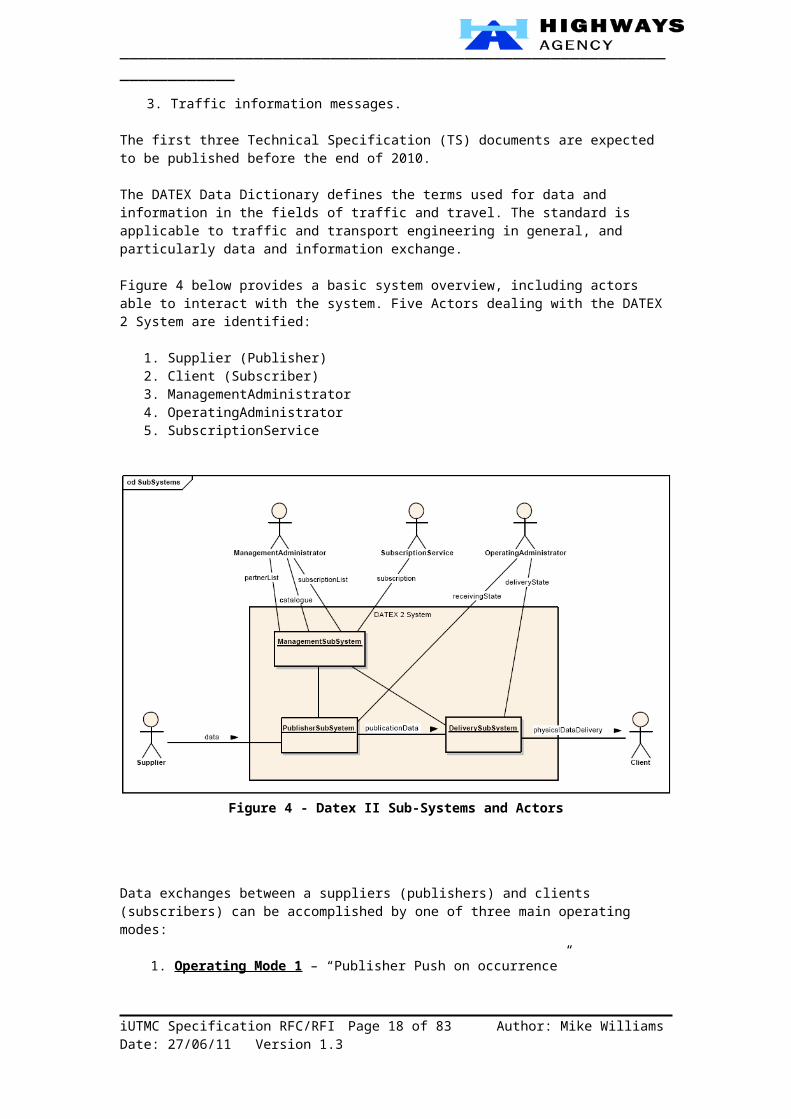
The DATEX Data Dictionary defines the terms used for data and information in the fields of traffic and travel. The standard is applicable to traffic and transport engineering in general, and particularly data and information exchange.
Figure 4 below provides a basic system overview, including actors able to interact with the system. Five Actors dealing with the DATEX 2 System are identified:
1. Supplier (Publisher)2. Client (Subscriber)3. ManagementAdministrator4. OperatingAdministrator5. SubscriptionService
Figure 4 - Datex II Sub-Systems and Actors
Data exchanges between a suppliers (publishers) and clients (subscribers) can be accomplished by one of three main operating modes:
iUTMC Specification RFC/RFI Page 12 of 58 Author: Mike Williams Date: 28/06/11 Version 1.3
_____________________________________________________________________
1. Operating Mode 1 – “Publisher Push on occurrence” o Data delivery initiated by the publisher every time data is changed.
2. Operating Mode 2 – “Publisher Push periodic” o Data delivery initiated by the publisher on a cyclic time basis.
3. Operating Mode 3 – “Client Pull“o Data delivery initiated by the Client, where data is returned as a response.
For the "Client Pull" operating mode, two implementation profiles have been defined for implementing this operating mode over the Internet: by direct use of the HTTP/1.1 protocol or via Web Services over HTTP. For the "Supplier Push" operating modes, one platform has been defined using Web Services over HTTP. This DATEX II Platform Specific Model (PSM) utilises the following Web Services implementation options:
Discovery: Not dynamic (UDDI is not used).Security: The security protocols must be negotiated between Suppliers and Clients prior
to the data exchange.Encryption: As above for security.
Whilst the Web Services-based profiles are pre-defined, the fact that Datex II employs a Model Driven Architecture (MDA) approach, with a Platform Independent Model (PIM), this lends itself to the development of other PSM deployments. The EA Team anticipate that external gateways to other Datex domains will adhere to the standard PSM profiles. However, within its own internal Datex domain, the HA may well define additional/alternative PSM’s and profiles, e.g. Web Services with UDDI; DDS, JMS or other publish and subscribe data exchange mechanisms.
References:http://www.datex2.eu/DATEX II V2.0 USER GUIDE v1.0, 01/07/2009DATEX II EXCHANGE MECHANISM, European Commission DG TREN, 08/02/2005DATEX II V2.0 EXCHANGE PLATFORM SPECIFIC MODEL, v1.0, 01/07/2009
13 Data Exchange
This section summarises a previous paper from 2007 which is reproduced in full in Annex C.
Within the HA and indeed across the ITS sector within the UK there are many interfaces between ITS systems which require the exchange of traffic and travel related information containing varying degrees of detail. This covers both the non-urban and urban domains and the public and private sectors.
In the past it has invariably been the case that bespoke interfaces have been developed to support the specific way the information was structured within the particular systems. Hence the format and structure of the exchanged data content has usually been bespoke without regard to any existing interfaces currently in use in the HA or ITS industry generally.
On the other hand the mechanics of the data exchange, or the way the information is exchanged, has usually followed the latest trends in ICT such as CORBA, HTTP, XML, SOAP etc. and has thus usually changed over time. DATEX II is the HA’s preferred standard interface for the exchange of traffic and travel information. The topics that can typically be conveyed by DATEX II include:
iUTMC Specification RFC/RFI Page 13 of 58 Author: Mike Williams Date: 28/06/11 Version 1.3

_____________________________________________________________________
Table 3 - Datex II TopicsAccidents All types with details of vehicle configuration, type,
load type including hazardous materials etc.Obstructions Vehicle, environmental, equipment damage, animal,
etc.Activities Public events, police/authority operations, public
disturbance activities, etc.Abnormal Traffic Conditions Abnormal traffic flows, queues, traffic flow trends,
waiting vehicles, etc.Driving Conditions Environmental/weather conditions, road surface
conditions, etc.Poor Road Infrastructure Damaged or failed road infrastructure.Road Works Maintenance and construction works.Network Management Restrictions, closures, lane configuration changes,
re-routing, etc.Sign Information VMS and matrix sign settings and faults, etc.Roadside Assistance Emergency services, vehicle repair/recovery, etc.Service Disruption Service area information, fuel shortage information,
etc.Measured Traffic Data Traffic status, travel times, traffic headway, flow,
speed, concentration, etc.Measured Weather/Pollution Data Precipitation, wind, air temperature, road surface
temperature, visibility, pollution, etc.Traffic View A combination of any event type information and
URI’s of available CCTV images relating to a defined stretch of the road network.
Figure 5 shows a more detailed view of the HA’s major operational systems and their interfaces (see Annex C - Glossary - Section 6 for a list of system acronyms). Not all interfaces shown between systems currently exist, but there is now a desire and realisation that many of these interfaces should exist to allow the various systems to work in a more co-ordinated and efficient manner. However, this “spaghetti” scenario is superseded by the Agency’s integration strategy so Figure 6 shows a simplified view based on the Enterprise Service Bus (ESB) design pattern.
It should be noted that the emphasis here is the exchange of Traffic Information – the exchange of Geospatial Data (as per INSPIRE and ROSATTE) is considered elsewhere within the Enterprise Architecture.
iUTMC Specification RFC/RFI Page 14 of 58 Author: Mike Williams Date: 28/06/11 Version 1.3

Figure 5 - Point-to-Point Operational Interfaces
iUTMC Specification RFC/RFI Page 15 of 58 Author: Mike Williams Date: 28/06/11 Version 1.3
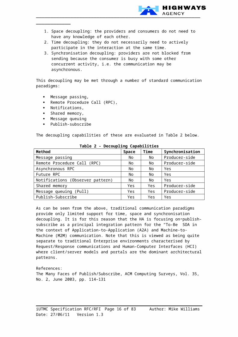
Figure 6 - Simplified Interfaces with ESB
iUTMC Specification RFC/RFI Page 16 of 58 Author: Mike Williams Date: 28/06/11 Version 1.3

_____________________________________________________________________
14 Heterogeneous Systems
15 Overview
The Agency requires a heterogeneous architecture which is:
Multi-vendor, Multi-service provider, Multi-channel, Multi-protocol, Multi-device, and Multi-platform.
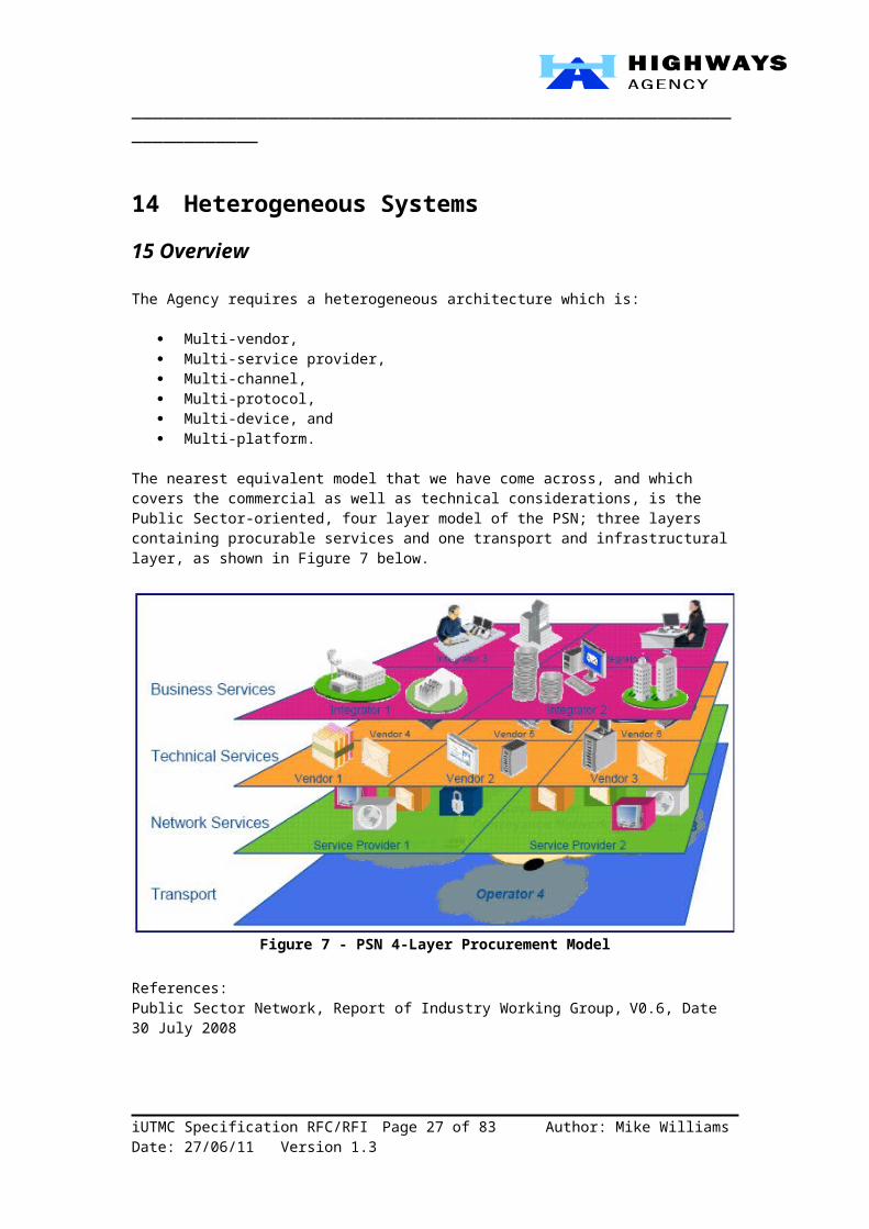
The nearest equivalent model that we have come across, and which covers the commercial as well as technical considerations, is the Public Sector-oriented, four layer model of the PSN; three layers containing procurable services and one transport and infrastructural layer, as shown in Figure 7 below.
Figure 7 - PSN 4-Layer Procurement Model
References:Public Sector Network, Report of Industry Working Group, V0.6, Date 30 July 2008
The next two sub-sections are based on a sub-set (Channels and Interfaces) of a capability mapping exercise, the objective of which was to derive a correctly levelled Technology Architecture structure/catalogue based on the HA’s EA Reference Model. This exercise was an initial iteration of the Reference Model and Business Architecture capabilities – an Elaboration to focus on the Technology Architecture with an emphasis on strategic ICT drivers and requirements.
iUTMC Specification RFC/RFI Page 17 of 58 Author: Mike Williams Date: 28/06/11 Version 1.3
_____________________________________________________________________16 Communication ChannelsThe Agency shall develop and maintain a Multi-Channel Architecture (MCA) in support of its business capabilities, especially those relating to the collection and dissemination of information.
Figure 8 – Multi-Channel Communications Capabilities
17 Voice
The Agency’s Multi-Channel Architecture shall support both fixed (wireline) and mobile voice communications.
Fixed voice communication channels currently include:
Emergency Roadside Telephones (ERT’s). The Public Switch Telephone Network (PSTN). The Government Telecommunications Network (GTN) which will be superseded by
the Public Sector Network (PSN).
Mobile voice communication channels currently include:
Terrestrial Trunked Radio (TETRA) which comprises a suite of open digital trunked radio standards used by Private Mobile Radio users such as the Highways Agency and Emergency Services (Police, Fire and Ambulance). Generally we refer to this as Airwave – the service currently provided in the UK by O2.
Mobile phone networks - GSM (Global System for Mobile communications) and 3G
(third generation).
18 DataThe Agency’s Multi-Channel Architecture shall support all current and future data requirements as follows.
iUTMC Specification RFC/RFI Page 18 of 58 Author: Mike Williams Date: 28/06/11 Version 1.3

_____________________________________________________________________Data channels may be classified in terms of:
Traffic Data; and Business Data.
Traffic data shall be collected, processed and disseminated in a real-time channel. Historical data shall be stored and made available from a Data Warehouse1 which forms part of the Business Intelligence2 capability – this may be considered as a logically separate ‘channel’.Business data is associated with the Agency’s information processing architecture. This is stored and accessed according to two principal classifications of data:
Structured data is held primarily in Relation DataBase Management Systems (RDBMS’s) and accessed through Line of Business (LoB) applications services typically through SQL (Structured Query Language).
Unstructured data is held in a number of knowledge-based repositories, including:o Content Management Systems (CMS), accessed via a web server/browser;o Document Management Systems (DMS), accessed by downloading
individual documents into office systems such as a word processor or spreadsheet; and
o Message stores, e.g. Electronic Mailboxes, accessed via an email client.
19 Video and Still Image
The Agency’s Multi-Channel Architecture shall support all current and future imaging technologies as follows.
The main applications and associated channels, within the Agency for video and still image are:
Video surveillance using Closed-Circuit Television (CCTV). Automatic Number Plate Recognition (ANPR). Currently, within the Agency the
images generally are not stored or transmitted across the network – only the associated data tags which are derived from images using Optical Character Recognition (OCR) and lossy encryption are. However, in future there is potential for images to be utilised for enforcement purposes if these are required.
This capability relates to the output side of the channel, i.e. for customers (including staff and partners) to be able to view the images (See Section 23.2.6.1 for the input side).
20 Text
The Agency’s Multi-Channel Architecture shall support all current and future text-based technologies as follows.
Text-based channels include:
SMS (Short Message Service). Electronic Mail. Instant Messaging.
Trials have been undertaken in the past for SMS-based alerts in applications such as pre-trip planning – this showed that there are applications which customers do value.
1 For a definition see http://en.wikipedia.org/wiki/Data_warehouse.2 For a definition see http://en.wikipedia.org/wiki/Business_intelligence.
iUTMC Specification RFC/RFI Page 19 of 58 Author: Mike Williams Date: 28/06/11 Version 1.3
_____________________________________________________________________Electronic mail is used extensively within the Agency and its partners. Customer contact is also available via this channel.
Instant messaging is not currently used but may become a future channel within the collaboration space.
21 In-CarThe Agency’s Multi-Channel Architecture shall support all current and future In-Car technologies as follows.
22 Digital RadioDigital Audio Broadcasting (DAB) is a digital radio technology for broadcasting radio stations, used in several countries, particularly in the UK and Europe.
Traffic Radio (www.trafficradio.org.uk) is a current service for keeping customers up-to-date with what’s happening on England’s motorways, major A roads and London’s main road network 24-hours a day, 365- days of the year.
With information provided directly from the Highways Agency’s National Traffic Control Centre (NTCC) and Transport for London’s (TfL) Traffic Control Centre’s, traffic bulletins are updated every ten minutes at peak times and every 20 minutes at other times.
23 RDS and RDS-TMCThe Radio Data System (RDS) arrived in the UK in the early 90’s, adding a basic data and text service to FM radio. Most FM radio stations in the UK use RDS. Along with the audio, small amounts of text and data are transmitted with the radio signal, and can be picked up and processed by radios which have an RDS decoder built-in. Such radio receivers can display this information.
A very useful bit of information sent, is something called the Traffic Announcement (TA) flag, which can be switched on when a radio station starts a travel report, and switched off at the end. The practical upshot of this is that an RDS radio can switch to a station carrying travel news, if necessary, pausing a cassette or a CD player, whilst local travel news is broadcast.
RDS-TMC stands for Radio Data Systems Traffic Message Channel. It provides road traffic information sent over FM radio to special in-car receivers. In the UK, RDS-TMC data is collected, and sent out over-air on specific FM radio stations. Some satellite navigation devices are capable of receiving RDS-TMC data, and updating routes to avoid traffic hotspots.
24 Future developments - CVHSCo-operative Vehicle Highway Systems (CVHS) offers a potential opportunity to move towards the ideal of 100% reliable and safe road journeys. New developments in automotive electronics are rapidly moving us towards intelligent vehicles which “think for themselves”, providing warnings or actuation to improve travel safety. However to allow these systems to develop to a stage of full efficient automation, information will be required from the road network. The infrastructure will need to communicate with vehicles’ on-board computers to
iUTMC Specification RFC/RFI Page 20 of 58 Author: Mike Williams Date: 28/06/11 Version 1.3

_____________________________________________________________________provide real-time travel conditions and close the information loop which will eventually lead to full automation.
This technology also supports Telematics applications like Norwich Union’s “Pay-As-You-Drive” insurance although here the roadside infrastructure is bypassed via mobile telephone networks (GPRS).
25 Roadside
The Agency’s Multi-Channel Architecture shall support all current and future roadside technologies as follows.
26 Video and Still Image
The main applications and associated channels, within the Agency for video and still image are as described in Section 3.2.3.
This capability relates to the input side of the channel, i.e. for devices to generate the images.
27 Traffic Sensor Data/Telemetry
ANPR is used for journey times. The other detectors described below are just some examples and range from (As-Is) deployed technology to theoretical research (candidate To-Be). They are included here to show there is a range of technology that we need to support in our To-Be Architecture.
28 Inductive Loops
Today inductive loops are most commonly used for traffic detection. New detector technologies are currently being investigated and those which have the potential to be deployed on Agency Roads in the near future are:
Microwave/Radar Infrared Detection Magnetic Anomaly Detector Fibre Optic Network/Longitudinal Detection Acoustic Detection
29 Microwave/RadarThis product has been designed for the detection and monitoring of vehicles at signalled junctions and other applications where the detection of moving targets is required in a long zone extending from the detector.
Their primary use is for detection associated with traffic signals, although they are a potential alternative to inductive loops for other Agency applications such as incident detection.
30 Infrared Detection
Infrared detectors find radiation ranging between 100-105 GHz. The detectors convert received energy into electrical signals that determine the presence of a vehicle by real-time signal processing. There are active and passive infrared detector models which have different detection abilities.
Passive detectors measure the energy emitted by a target or the image of the detection zone.
iUTMC Specification RFC/RFI Page 21 of 58 Author: Mike Williams Date: 28/06/11 Version 1.3

_____________________________________________________________________Active detectors emit invisible infrared low-energy by light-emitting diodes or high energy by laser diodes to the detector zone and measures the time for reflected energy to return to the detector. A lower return time denotes the presence of a vehicle.
The detectors measure vehicle speed by transmitting two or more beams and recording the times at which the vehicle enters the detection zone of each beam.
31 Magnetic Anomaly Detector
Magnetic detectors sense vehicles by measuring effects of the vehicles’ metallic components on the Earth’s magnetic field.
Magnetic detectors can detect volume, speed, presence and occupancy. Their configurations may be single, double, or multiple, depending on monitoring requirements. They generally require multiple detectors per lane due to the narrow focus of the detection field.
A micro-loop detector is a type of point detector. The installation requires a hole in the pavement, one inch in diameter and 20 inches deep, with a straight one fourth inch saw cut. Although there is still disruption to traffic, the micro-loop is considered to be “non-intrusive” compared to inductive loops. The 3M type of MAD mounts under the road in a plastic pipe. This makes it particularly well suited for viaducts and bridges.
32 Fibre Optic Detectors
Fibre Optic Sensors have no electronic components, which gives them high reliability and immunity to electro-magnetic interference. With the available bandwidth, over 100 sensors can be multiplexed together on a single fibre. Remote interrogation of the sensors is possible from a distance as great as 50 kilometres.
Fibre optic sensors have the potential to measure vehicle dynamics in the road, and early tests of longitudinal sensors (Fibre Optic Longitudinal Detector) have shown they could potentially provide a cost effective alternative to traditional loop and WIM technologies. These are currently experiemental.
33 Acoustic Detection
Passive acoustic detectors can detect volume, speed, occupancy, and classification. They measure the acoustic energy or audible sounds produced by a variety of sources within a passing vehicle.
Sound energy increases when a vehicle enters the detection zone and decreases when it leaves. A detection threshold determines the termination of the vehicle presence signal. Sounds from locations outside the detection zone are attenuated.
The detector measures multi-lane traffic count, occupancy, and vehicle speed. Each detector can replace up to five dual-loops when installed 'side-fire'. These are currently experiemental.
34 Weather Sensor Data/Telemetry
Weather Detection Systems use different types of sensors to detect current weather conditions such as:
Atmospheric water vapour Pavement temperatures
iUTMC Specification RFC/RFI Page 22 of 58 Author: Mike Williams Date: 28/06/11 Version 1.3

_____________________________________________________________________ Fog density Ice levels Snow levels
These sensors are often integrated with other weather-related technologies to forecast weather conditions. Road weather information systems, for example, transmit pavement temperatures and other information to traffic management centres which can, in turn, make decisions on whether to apply anti-icing chemicals or begin snowplough operations, as well as alert travellers to adverse driving conditions.
35 Signals
Below are examples of signals in use on the Highways Agency network.
36 Ramp Metering
Ramp metering is a key measure for reducing delays at junctions. It works by managing the traffic on slip roads.
During busy periods, signals release just a few vehicles at a time. This prevents merging and mainline traffic from bunching together and creating a bottleneck which delays everyone.Sensors in the road monitor the congestion and adjust the signal timings. The system also monitors the slip road to minimise the possibility of queues forming on local authority roads.
37 Central Reserve Post-mounted Signals (Matrix Signals)
Caters for up to 3-lane motorways and major trunk roads. Spaced at 3km intervals.
Limited to display advisory fog warnings, speed restrictions and lane closures with amber flashing warning lanterns.
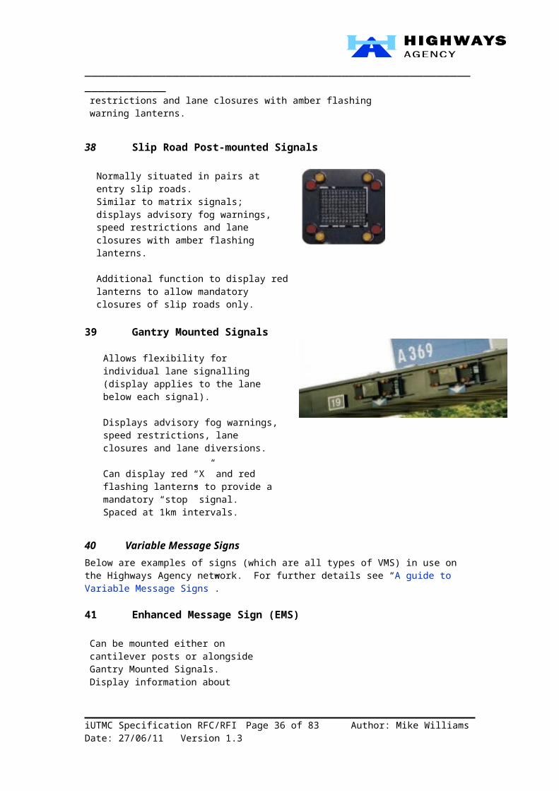
38 Slip Road Post-mounted Signals
Normally situated in pairs at entry slip roads. Similar to matrix signals; displays advisory fog warnings, speed restrictions and lane closures with amber flashing lanterns. Additional function to display red lanterns to allow mandatory closures of slip roads only.
39 Gantry Mounted Signals
iUTMC Specification RFC/RFI Page 23 of 58 Author: Mike Williams Date: 28/06/11 Version 1.3
_____________________________________________________________________
Allows flexibility for individual lane signalling (display applies to the lane below each signal).
Displays advisory fog warnings, speed restrictions, lane closures and lane diversions.
Can display red “X” and red flashing lanterns to provide a mandatory “stop” signal. Spaced at 1km intervals.
40 Variable Message SignsBelow are examples of signs (which are all types of VMS) in use on the Highways Agency network. For further details see “A guide to Variable Message Signs”.
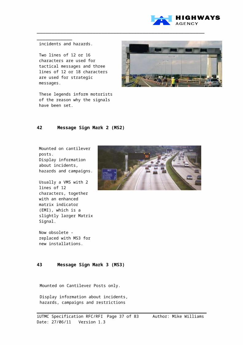
41 Enhanced Message Sign (EMS)
Can be mounted either on cantilever posts or alongside Gantry Mounted Signals. Display information about incidents and hazards. Two lines of 12 or 16 characters are used for tactical messages and three lines of 12 or 18 characters are used for strategic messages.
These legends inform motorists of the reason why the signals have been set.
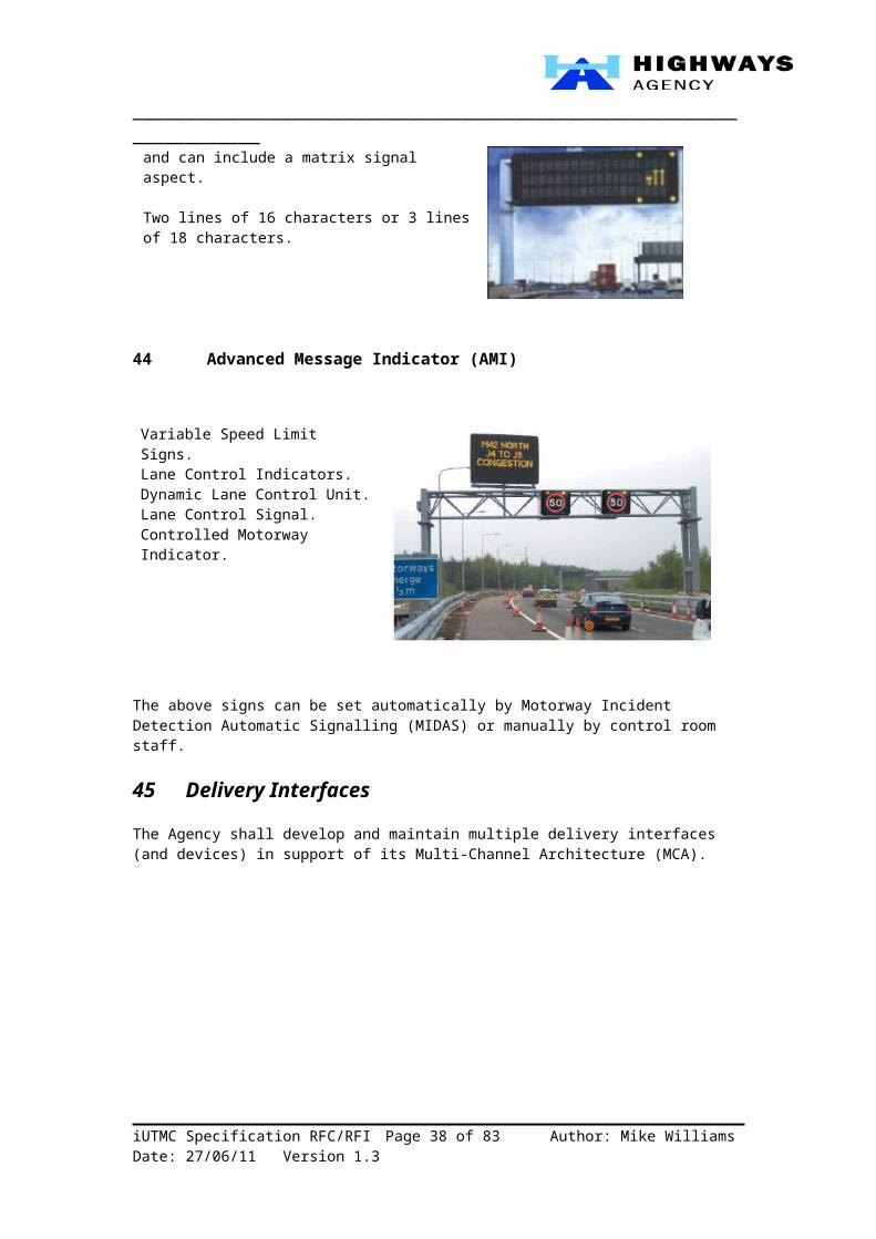
42 Message Sign Mark 2 (MS2)
Mounted on cantilever posts. Display information about incidents, hazards and campaigns.
Usually a VMS with 2 lines of 12 characters, together with an enhanced matrix indicator (EMI), which is a slightly larger Matrix Signal.
Now obsolete - replaced with MS3 for new installations.
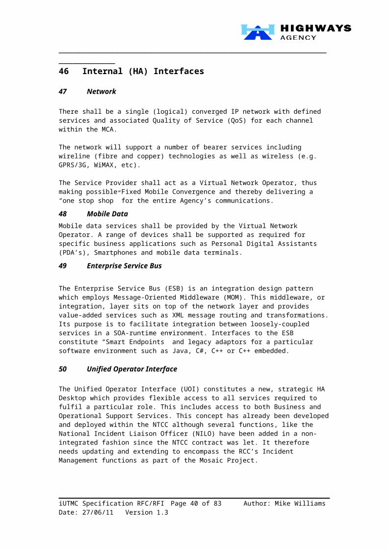
43 Message Sign Mark 3 (MS3)
iUTMC Specification RFC/RFI Page 24 of 58 Author: Mike Williams Date: 28/06/11 Version 1.3

_____________________________________________________________________
Mounted on Cantilever Posts only.
Display information about incidents, hazards, campaigns and restrictions and can include a matrix signal aspect.
Two lines of 16 characters or 3 lines of 18 characters.
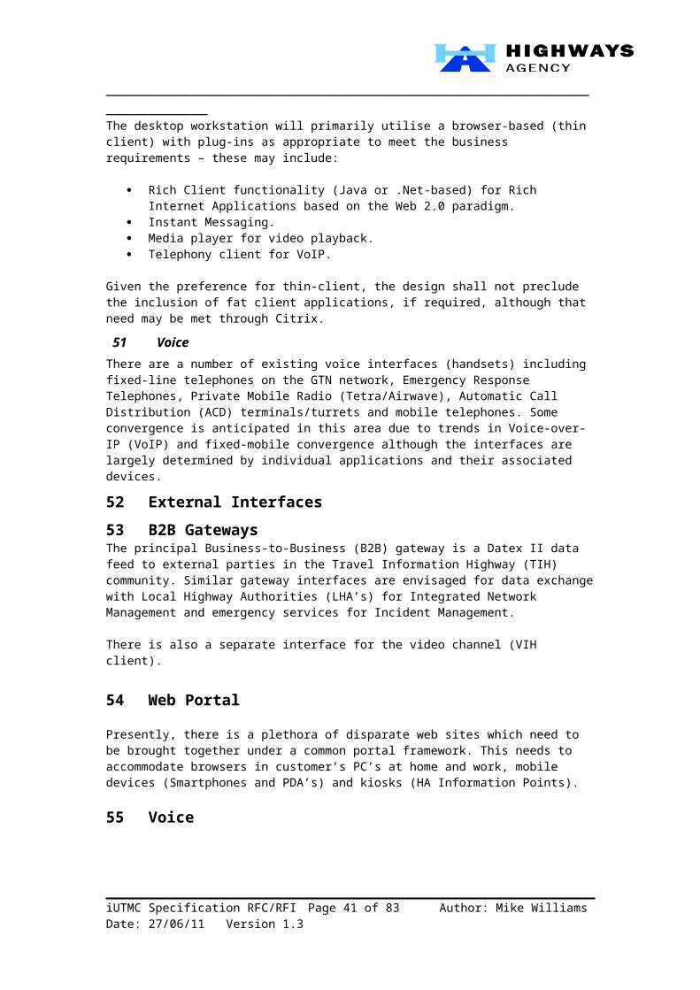
44 Advanced Message Indicator (AMI)
Variable Speed Limit Signs.Lane Control Indicators.Dynamic Lane Control Unit.Lane Control Signal.Controlled Motorway Indicator.
The above signs can be set automatically by Motorway Incident Detection Automatic Signalling (MIDAS) or manually by control room staff.
45 Delivery InterfacesThe Agency shall develop and maintain multiple delivery interfaces (and devices) in support of its Multi-Channel Architecture (MCA).
iUTMC Specification RFC/RFI Page 25 of 58 Author: Mike Williams Date: 28/06/11 Version 1.3
_____________________________________________________________________
Figure 9 – MCA Delivery Interface Capabilities
iUTMC Specification RFC/RFI Page 26 of 58 Author: Mike Williams Date: 28/06/11 Version 1.3
_____________________________________________________________________46 Internal (HA) Interfaces
47 Network
There shall be a single (logical) converged IP network with defined services and associated Quality of Service (QoS) for each channel within the MCA.
The network will support a number of bearer services including wireline (fibre and copper) technologies as well as wireless (e.g. GPRS/3G, WiMAX, etc).
The Service Provider shall act as a Virtual Network Operator, thus making possible Fixed Mobile Convergence and thereby delivering a “one stop shop” for the entire Agency’s communications.
48 Mobile DataMobile data services shall be provided by the Virtual Network Operator. A range of devices shall be supported as required for specific business applications such as Personal Digital Assistants (PDA’s), Smartphones and mobile data terminals.
49 Enterprise Service Bus
The Enterprise Service Bus (ESB) is an integration design pattern which employs Message-Oriented Middleware (MOM). This middleware, or integration, layer sits on top of the network layer and provides value-added services such as XML message routing and transformations. Its purpose is to facilitate integration between loosely-coupled services in a SOA-runtime environment. Interfaces to the ESB constitute “Smart Endpoints” and legacy adaptors for a particular software environment such as Java, C#, C++ or C++ embedded.
50 Unified Operator Interface
The Unified Operator Interface (UOI) constitutes a new, strategic HA Desktop which provides flexible access to all services required to fulfil a particular role. This includes access to both Business and Operational Support Services. This concept has already been developed and deployed within the NTCC although several functions, like the National Incident Liaison Officer (NILO) have been added in a non-integrated fashion since the NTCC contract was let. It therefore needs updating and extending to encompass the RCC’s Incident Management functions as part of the Mosaic Project.
The desktop workstation will primarily utilise a browser-based (thin client) with plug-ins as appropriate to meet the business requirements – these may include:
Rich Client functionality (Java or .Net-based) for Rich Internet Applications based on the Web 2.0 paradigm.
Instant Messaging. Media player for video playback. Telephony client for VoIP.
Given the preference for thin-client, the design shall not preclude the inclusion of fat client applications, if required, although that need may be met through Citrix.
51 VoiceThere are a number of existing voice interfaces (handsets) including fixed-line telephones on the GTN network, Emergency Response Telephones, Private Mobile Radio (Tetra/Airwave), Automatic Call Distribution (ACD) terminals/turrets and mobile telephones. Some convergence is anticipated in this area due to trends in Voice-over-IP (VoIP) and fixed-mobile convergence although the interfaces are largely determined by individual applications and their associated devices.
iUTMC Specification RFC/RFI Page 27 of 58 Author: Mike Williams Date: 28/06/11 Version 1.3

_____________________________________________________________________52 External Interfaces53 B2B GatewaysThe principal Business-to-Business (B2B) gateway is a Datex II data feed to external parties in the Travel Information Highway (TIH) community. Similar gateway interfaces are envisaged for data exchange with Local Highway Authorities (LHA’s) for Integrated Network Management and emergency services for Incident Management.
There is also a separate interface for the video channel (VIH client). 54 Web Portal
Presently, there is a plethora of disparate web sites which need to be brought together under a common portal framework. This needs to accommodate browsers in customer’s PC’s at home and work, mobile devices (Smartphones and PDA’s) and kiosks (HA Information Points).
55 Voice
External public interfaces for the voice channel currently comprise the HA Information Line (HAIL), Traffic Radio and an Interactive Voice Response (IVR) facility at the NTCC. For operational partners there are a number of existing voice interfaces (handsets) including fixed-line telephones, Private Mobile Radio (Tetra/Airwave) with other emergency services, and mobile telephones. Little change is anticipated in this area.
56 In-Car
In-car devices essentially comprise satellite navigation (sat-nav) systems and, in future, will be expanded to include the On-Board Units (OBU’s) used for Telematics in Cooperative Vehicle Highways Systems (CVHS). The sat-nav devices interface indirectly via Value-Added Service Providers (such as TrafficMaster and TomTom) although future CVHS interfaces are anticipated through the UTMC architecture (node-type “E” also known as Vehicle-to-Infrastructure and/or Infrastructure-to-vehicle).
57 Channel Summary
In order to facilitate the Multi-Channel Architecture and associated multi-protocol capability, the network will be logically segmented as illustrated in Figure 10 below.
Figure 10 - Logical Channels
iUTMC Specification RFC/RFI Page 28 of 58 Author: Mike Williams Date: 28/06/11 Version 1.3

_____________________________________________________________________
58 Candidate Architecture Building Blocks
59 Overview
For the Outstation and Roadside domain, the HA has adopted the UTMC Reference Architecture as its starting point. The UTMC Logical Model is shown in Figure 11 below.
Figure 11 - UTMC Logical Model
Node AIn the context of this part of the architecture (which considers only Operational ITS) Node A types can be any external system which communicates with internal HA systems via an external gateway (and firewall).Node BThese are Traffic Management Centres (TMC’s) – currently divided into the National Traffic Control Centre (NTCC) and the Regional Control Centres (RCC’s).Node CThese are intermediate nodes between Traffic Management Centres and roadside devices. They include TMC satellite locations/depots, Remote Maintenance Centres (RMC’s), Service Provider locations, mobile Incident Support Unit’s and MIDAS outstations.Node D
iUTMC Specification RFC/RFI Page 29 of 58 Author: Mike Williams Date: 28/06/11 Version 1.3
_____________________________________________________________________These comprise the main roadside components and devices – there are several thousand of these within the HA.Node EIn-vehicle systems are of considerable strategic importance as this is where the major growth lies in terms of volume and complexity due to future developments in automotive electronics and Co-operative Vehicle Highway Systems (CVHS). Whereas the number of Node D’s run into thousands, in the future there could be millions of Node E’s which is why IPv6 is mandated in the “To-Be” network architecture.
Inter-node data interfaces are as follows:1. The primary interface for external systems within the ITS domain is Datex II,
including the standard three main operating modes – “Publisher Push on occurrence”, “Publisher Push periodic”, and “Client Pull“. Others may be made available such as RSS feeds.
2. In-station interfaces will be via an Enterprise Service Bus (ESB) which typically uses the Java Messaging Service (JMS).
3. There will possibly be two separate channels here: 1) supporting traditional request/response communications using Web Services (WS-*) over HTTP and TCP/IP, and/or SNMP over UDP/IP; and 2) Real-Time publish-subscribe using OMG’s Data Distribution Service (DDS) with the RTPS wire-protocol over UDP/IP.
4. No implementations are envisaged at this stage.5. Same as (3) above for communications protocols. However, in order to achieve the
required abstraction for multi-vendor and legacy devices, devices must be service enabled using some form of Service-Oriented Device Architecture (SODA) – further details are provided later in this document.
6. As per CALM (Continuous Air-interface for Long and Medium range communications) standards.
The functional model for UTMC is shown in Figure 12 overleaf. Each of the component parts are described below – note that the UTMC Technical Specifications (TS003) state the “As-Is” position, whereas here we are looking towards an iUTMC-driven “To-Be” variant.
User InterfaceWe anticipate that most, if not all, future applications will be browser-based and delivered within a Unified Operator Interface (UOI) – a standardised HA Desktop of the future. This, however, may consist of standard HTML text and graphics but, increasing, is likely to adopt emerging Web 2.0-based Rich Internet Application (RIA) technologies such as Ajax (asynchronous JavaScript and XML).Applications and “Private Databases”Applications and their associated “private databases” will be COTS-based and, as such will be supplied by multiple vendors operating in an open market. Their internal workings are deemed to be “encapsulated” and, as such, are viewed by the HA as “Black Boxes”. This also applies equally to any legacy systems that may be retained and re-used on the basis that they continue to offer the most cost-effective solution at a given point within the system lifecycle. The physical interfaces which expose the application’s business services will need to be mapped against the previous logical model but the two functional interfaces shown in this functional model are effectively:
A. Software as a Service.B. Data as a Service.
Information Layer – data objects and dictionaries - Common DatabaseThe data objects here are defined largely within the HA’s ITS Metadata Registry – this currently contains “recommended” models but here the aim is to develop a “preferred” model. The strategic intention is to adopt the road domain subset of Datex II (Layer A) as the basis for the development of a Common Information Model (CIM), with extensions as necessary for operational services. Such extensions may, for example, include UTMC-based, Common Database models. Equally though, where interoperability is required with external UTMC systems, as required for Integrated Network Management (INM), this may also be achieved through XSLT transformations.
iUTMC Specification RFC/RFI Page 30 of 58 Author: Mike Williams Date: 28/06/11 Version 1.3

_____________________________________________________________________
Figure 12 - UTMC Functional Model
Applications Layer – services to exchange data between identified system nodesIn principle, the HA’s strategy is to adopt an “Intelligent Highways” infrastructure based on the Enterprise Service Bus (ESB) design pattern. Given the need for real-time data collection from the roadside, the OMG’s Data Distribution Service (DDS) is seen as a prime candidate for this section of the technical framework. This is discussed further in the next section.Transport Layer – network addressing, routing and transmission protectionThis equates to Layers 3 and 4 of the OSI 7-Layer Reference Model. Layer 3 standardises on the Internet Protocol (IP). Layer 4 supports User Datagram Protocol (UDP) for connectionless and Transmission Control Protocol (TCP) for connection-oriented communications.Sub-network Layer – packet transmission and physical interfaceThis equates to Layers 1 and 2 of the OSI 7-Layer Reference Model. For the HA these are “encapsulated” inside the NRTS “cloud”.Plant Layer – wireline/fibre and wireless bearersThis equates to the copper and fibre-optic cables in the ground together with radio-based, or wireless channels, such as GPRS, 3G and WiMAX. For the HA these are “encapsulated” inside the NRTS “cloud”.System ManagementThe UTMC Technical Specifications (TS003) states that the following system management facilities shall be provided as a minimum:
a) management/monitoring to ensure the operational status of components and communication links; and
b) facilities to configure components and communication links.They also stipulate SNMP as the preferred standard. However, emerging requirements such as remote firmware upload/download, remote configuration and diagnostics is likely to extend the need for more sophisticated methods – this is discussed further in later sections.
iUTMC Specification RFC/RFI Page 31 of 58 Author: Mike Williams Date: 28/06/11 Version 1.3
_____________________________________________________________________
60 Data Distribution Service (DDS)
61 What is DDS?
DDS is an OMG standard, an API specification and an interoperability wire-protocol that defines a Data-Centric Publish-Subscribe (DCPS) architecture for connecting anonymous information providers with information consumers. Like SOA, DDS promotes loose coupling between system components. A distributed application is composed of data providers and consumers, each potentially running in a separate address space, possibly on different computers.
Figure 13 A Real-Time Data-Centric Publish-Subscribe Architecture
A data provider publishes typed data-flows, identified by names called “topics,” which consumers can subscribe to. An application may simultaneously fulfil the roles of data provider and consumer. The DDS APIs allow data providers and consumers to present type-safe programming interfaces. A typical DDS application architecture can be represented as a software “data-bus."
62 How is DDS different?
DDS enables, for the first time, the creation of a globally-accessible shared data-space that can be used as the foundation for the correlation and analysis processes required to monitor the system, detect intrusion and initiate remedial action.
A property of the DDS data-centric publish-subscribe architecture is that component interfaces are decoupled in space (providers and consumers can be anywhere), time (delivery may be immediately after publication or later), flow (delivery QoS can be precisely controlled), platform (providers and consumers can be on different implementation platforms, and written in different languages), and multiplicity (there can be multiple providers and consumers of a topic).
iUTMC Specification RFC/RFI Page 32 of 58 Author: Mike Williams Date: 28/06/11 Version 1.3

_____________________________________________________________________
Figure 14 - Peer-to-Peer with QoS
63 What about Request/Response Support?
When two applications communicate via Messaging, the communication is intrinsically one-way. However, some applications may want a two-way conversation. In this scenario, when an application sends a message, how can it get a response from the receiver? It can use the Request-Reply message pattern, by sending a pair of Request-Reply messages, each on its own channel, as shown in Figure 15 below.
Figure 15 - Request-Reply Integration pattern (Source: www.eaipatterns.com)
In DDS, this can be implemented using the Command Pattern3 as follows. A command is identified by a unique ClientID obtained from the DDS middleware along with an invocationID. The CmdRequest operation issues a request on the CmdRequestTopic, while the CmdResponse operation returns a response on the CmdResponseTopic. Clients subscribe to the CmdResponseTopic using a content-filter on the ClientID so they only receive responses to their own requests. Requests and responses are correlated according to the invocationID.
3 “The Command Pattern: Implementing Distributed RPC with QoS using the Data Distribution Service”, Rajive Joshi, RTI, 17/06/09.
iUTMC Specification RFC/RFI Page 33 of 58 Author: Mike Williams Date: 28/06/11 Version 1.3

_____________________________________________________________________64 What about Developer Support?Data-centric [DDS] developers, using the Data-Oriented Programming approach, don't write or specify code as with traditional programming techniques. Instead, they construct a data model that defines who needs what data. Then they answer the QoS questions: How fast is the data coming, i.e. at what frequency are samples being published? Does each instance need to be totally reliable or will the recipient wait for the next published sample (which may only be seconds away)? Do I need to store [persist] it for logging purposes? Where is it coming from? What happens if a node fails and the data is critical?
This design should be intuitive - it needs to mirror time-critical information-delivery systems in the real-world. All mass-media communications, including television, radio, magazines, and newspapers, are based fundamentally on the publish-and-subscribe communication model.
Designers have always built interface specifications that detail which information flows between system components. With a publish-subscribe information bus, the interface is the design; interface specifications can essentially be directly implemented (see Figure 16, below). Thus, the data-centric design technique eliminates a number of intermediate steps, and with them all the overhead and opportunity for error they entail.
Figure 16 - Conventional vs. data centric system design
Table 4 - A Case Study: Tokyo's Highway Line SystemTokyo's Highway Line system consists of a central information-control centre and hundreds of information kiosks and terminals scattered along the city's highway system. They needed a low maintenance, high reliability communications system that was sufficiently robust for delivery of constant updates to the kiosks. The drivers and passengers who are stopped at the parking area rest stops are able to get information on traffic conditions, projected arrival times to particular locations, alternate routes, and enforcement points where traffic is being redirected or controlled due to obstructions in the roadways caused by construction or accident.
The size and complexity of such a widely distributed real-time system pose a number of specific design challenges, notably:
1. How to provide reliable real-time information to commuters about arrival times, traffic problems, changes in schedules, potential problems and alternate routes;2. Ensuring the provision of information to transit officials and employees on a timely basis;3. How to ensure delivery of this information on transmission links that vary in bandwidth, signal to noise ratio, and physical location;4. How to develop, operate, maintain and eventually upgrade a complex system running on a variety of computer server and client platforms with diverse hardware and software incompatibilities.
iUTMC Specification RFC/RFI Page 34 of 58 Author: Mike Williams Date: 28/06/11 Version 1.3

_____________________________________________________________________
By using a publish-subscribe model based on DDS, the developers of the Highway Line network designed a system using asynchronous message passing between concurrently operating subsystems, connecting a variety of anonymous information producers (central office) with many other equally anonymous information consumers (kiosk and terminals). In such a system, when a data producer " the server - publishes some data on a topic, all the consumers " the kiosks and terminals - subscribing to that topic receive it. The data producers and consumers remain anonymous, resulting in a loose coupling of sub-systems and a robust service that decouples participants from one another, provides location transparency, and the flexibility to dynamically add or remove elements.
In addition to the benefits of performance and flexibility inherent in the data-centric publish-subscribe model, what also appealed to the Tokyo developers was the speed and efficiency of the development process. Unlike the typical client/server link, DDS essentially provides a connectionless API.
Thus it does not require that the system designer get involved in the underlying communications protocols. The developer need only need to tell the system what the bandwidth constraints are, the information needed at each node, what actions needed to be taken, when to send it or to receive it, and what is required in response. Instead of a direct, active link to a server in which the client is required to query for updates, DDS is very information centric, and does not require such active linkages, which require constant updating.
This allowed the Tokyo system developers to simply tell the DDS API what information is needed at which terminal and on what schedule. As a subscription protocol, the system designers can designate beforehand the quality of service and the delivery profile rather than negotiating this each time a transaction is initiated.
The flexibility of the publish-subscribe framework and the fact that it is independent of the underlying server, terminal or network hardware or software configuration also gives the developers of the Highway Line network the ability to be more open ended in relation to future extensions of the system in terms of number of terminals, the underlying hardware or OS, the physical network and the bandwidth required.
An example of an OMG MDA-based development tool with DDS support is Sparx Systems’ Enterprise Architect with MDG Technology for DDS. This tool provides support for modelling complex, data-centric publish-subscribe services using UML 2.1. Features include:
Specify Data-Centric Publishers, Subscribers, Topics and QoS Policies Define Data Local Reconstruction mappings for DDS data access Create heterogeneous DDS applications across different host environments. Generate executable source code in C, C++,C# and Java using MDA (Model Driven
Architecture) Target DDS implementations for both RTI and OpenSplice implementations.
65 What are the benefits of DDS?The benefits of using DDS from a HA perspective are as follows:
It is a recognised international [OMG] standard. It provides for loose-coupling required for SOA and System-of-Systems approaches. It provides a real-time, deterministic Quality of Service (QoS) which provides for low
latency and high scalability. Has much in common with other OMG standards, including the Model-Driven
Architecture and CORBA Interface Definition Language (IDL) as used within the UTMC community.
iUTMC Specification RFC/RFI Page 35 of 58 Author: Mike Williams Date: 28/06/11 Version 1.3
_____________________________________________________________________ It has broad take-up in the real-time, embedded systems market including notably,
the U.S. Department of Defence (DoD) – originators of the Arpanet project in 1996 which led to today’s Internet.
It is has an open architecture and API’s for cross-vendor portability, providing heterogeneous support:
o Language support includes C, C++, Java and .Net (C#, C++ and CLI).o OS support includes Windows, Linux, UNIX, Embedded and Real-Time.o The only international standard for Real-Time Publish-Subscribe (RTPS) wire
protocols.o Multiple implementations, commercial and open source:
Seven supporting the API, Four of which support RTPS.
Provides integration with SQL databases and Web Services. RTPS adopted as an International Electrical Commission standard (IEC 61158) in
2004. Multi-channel data writers provide the ability to send data over multiple multicast
groups according to application defined filtering criteria which results in:o Reduced network congestion.o Reduced CPU load.o Ease of use – no need to fragment topics.o Subscriber side CPU load reduction of 90%.o Publisher side CPU load reduction of 20%.o Increased throughput of 50%.
66 Who uses DDS?Since its introduction in 2003, DDS has achieved rapid adoption as a standard for integrating and developing high-performance real-time systems. It is a mandated standard for publish-subscribe messaging by the U.S. Department of Defence (DoD) Information Technology Standards Registry (DISR) and Global Information Grid (GIG). Programmes that have adopted DDS include the U.S. Navy's Open Architecture Computing Environment (OACE) and FORCEnet; the U.S. Army's Future Combat Systems (FCS); and the joint Air Force, Navy and DISA Net-Centric Enterprise Solutions for Interoperability (NESI).
DDS has been embraced by many DoD programs, including SOSCOE4, and Prime contractors working on Open Architecture initiatives. Users include virtually all major US Prime defence contractors, US defence research laboratories, plus a growing number of commercial organisations in the telecommunications, transportation, and financial services sectors.
References:http://en.wikipedia.org/wiki/Data_Distribution_Service Data-Oriented Architecture: A Loosely-Coupled Real-Time SOA, Rajive Joshi, RTIOpenSplice Overview White Paper, Hans van’t Hag, PrismTechThe data-centric future, Stan Schneider, EmbeddedSystems Europe, Nov-Dec 2006Embedded to Enterprise (e2E) comes of age, Mark Hamilton, ESE Magazine/Embedded Enterprise 06Case Study 1: Tokyo HighwaysCase Study 2: US Navy
4 System-of-Systems Common Operating Environment.
iUTMC Specification RFC/RFI Page 36 of 58 Author: Mike Williams Date: 28/06/11 Version 1.3
_____________________________________________________________________
67 Example Scenario
An example of DDS deployed within the NTCC sub-systems is shown in below.
Figure 17 - DDS applied to NTCC Sub-Systems
In this example, the roadside devices publish their data to the relevant channels, or topics, whilst each of the TMC (NTCC/RCC) sub-systems and the Variable Message Signs (VMS) subscribe to the topics associated within their respective domains of interest.
68 Roadside components and devices
69 Introduction
The monitoring and controlling of the physical environment, such as weather and traffic movement, has long been possible through devices from basic sensors and actuators to complex equipment and controllers such as ANPR’s, CCTV and VMS signs. These devices reside at the “edge” network and are generally regarded as “embedded” systems. As shown in Figure 18, these edge network devices provide an interface between the physical realm (the real, analogue world) and the digital realm of modern Enterprise information systems.
iUTMC Specification RFC/RFI Page 37 of 58 Author: Mike Williams Date: 28/06/11 Version 1.3
_____________________________________________________________________
Figure 18 - Sensors and Actuators
In the iUTMC context, these comprise the main roadside components and devices at Node D in the Logical Model (as described in Section 4.1). Also, as stated earlier (in Section 3.1), the Agency requires a heterogeneous architecture which is:
Multi-vendor, Multi-service provider, Multi-channel, Multi-protocol, Multi-device, and Multi-platform.
We’re also moving towards a Service-Oriented Architecture (SOA) as described in Section 2.4. In order to achieve all of this, we believe there is a need for distributed devices to be presented to the communications and integration medium as a service, as shown in Figure 19.
Figure 19 - A Device Service
In this model, responsibility for encapsulating services can be appropriately abstracted to the suppliers who know them best:
One side deals with their device-specific connections and protocol.
iUTMC Specification RFC/RFI Page 38 of 58 Author: Mike Williams Date: 28/06/11 Version 1.3

_____________________________________________________________________ The other side deals with network interfaces needed to exchange data over a defined
SOA protocol binding.
This way, a standard specified service can have a wide variety of underlying hardware, firmware, software and networking implementations. It insulates the SOA from device interfaces and proprietary vendor implementations. The resulting Service-Oriented Device Architecture (SODA) is all about integration.
There are at least two competing SODA standards that we are currently aware of – Eclipse and ITEA. These are each covered in the next two sub-sections.
70 SODA – Eclipse Project
Eclipse is an open source community, whose projects are focused on building an open development platform comprised of extensible frameworks, tools and runtimes for building, deploying and managing software across the lifecycle. The Eclipse Foundation is a not-for-profit, member supported corporation that hosts the Eclipse projects and helps cultivate both an open source community and an ecosystem of complementary products and services.
The Service-Oriented Device Architecture (SODA) Project is an initiative to standardise and simplify the integration of devices with enterprise solutions by introducing a services-based programming model. SODA leverages existing and emerging standards from both the embedded-device and IT domains to provide well-defined interfaces for hardware devices to a service-oriented architecture (SOA). Its goal is to enable developers to interact with sensors and actuators just as business services are used within the Enterprise SOA domain.
The core framework components that support the development and runtime environment of SODA services are Device Kit and Service Activator Toolkit. These use the OSGi Alliance’s (formerly known as the Open Services Gateway initiative, now an obsolete name) Java-based service platform and framework. This is covered further in 74 Embedded Java and OSGi.
References:http://www.eclipse.orgSODA: Service-Oriented Device Architecture, Scott de Deugd, et al, Pervasive Computing, 2006Service Oriented Device Architecture (SODA), EclipseCon 2007, Jeffrey Ricker/Paul LymanMarch 6, 2007
71 SODA – ITEA Project and DPWS
ITEA (Information Technology for European Advancement) is a strategic pan-European programme for advanced pre-competitive R&D in software for Software-intensive Systems and Services (SiS).
The objective of ITEA’s SODA project was to create a service-oriented ecosystem built on top of the foundations laid by their SIRENA framework for high-level communications between devices based on SOA.
This version of “SODA” comprises a Service Oriented Device and Delivery Architecture (SODDA). Its aim was to deliver a service-oriented ecosystem for embedded devices, neutral with respect to operating systems and programming languages and independent from physical resources, networks and protocols, as well as from application domains. This ecosystem features:
iUTMC Specification RFC/RFI Page 39 of 58 Author: Mike Williams Date: 28/06/11 Version 1.3
_____________________________________________________________________ An infrastructure for service-oriented systems based on embedded devices. A methodology and guidelines helping users to move from traditional architectures
towards service-oriented ones, Tools supporting the design, development and operations of service-oriented
applications.
Figure 20 - The ITEA SODDA Approach
The technical framework covers a number of domains including:
Industrial Home Automation Building Automation Telecom Automotive (future)
The SODDA device architecture is strongly influenced by the Devices Profile for Web Services (DPWS) which has recently become an approved OASIS standard - further information is provided in the next sub-section. This Web Service influence is based on the premise that the basic infrastructure requirement is to provide connectivity between devices using an IP-based network. However, the technical framework recognises that in many cases, more advanced capabilities will be required, such as:
• High-performance, real-time communications.• Secure communications.• Reliable messaging.• Management services.• Extended discovery mechanisms.• Event brokering.
The specification states that the above capabilities are implemented using protocols (such as WS-Security, WSReliableMessaging) and generic services compatible with standard enterprise information technology, such as JEE and ESB, in order to support connectivity to Enterprise ICT systems. A requirement and capability description language also supports dynamic negotiation of Quality of Service (QoS), based on these advanced capabilities. A QoS model provides a common understanding about devices QoS capabilities from an integration perspective.
iUTMC Specification RFC/RFI Page 40 of 58 Author: Mike Williams Date: 28/06/11 Version 1.3
_____________________________________________________________________
The extensibility layer supports pluggable extensions including:
• Security through message authentication and encryption.• Reliable delivery of messages.• Support for management protocols.• Support for high-performance messaging (Binary XML).• Other protocols to be defined.
Also, the extensibility layer ensures modularity such that:
• Additional protocol modules are only deployed when needed, in order to minimise resource utilisation.
• Deployment descriptors are used to configure the stack and describe available features such as QoS requirements.
• Deployed modules should have a minimal impact on existing services.
References:http://www.soda-itea.orgTechnical Framework Description – SODA, v1.0.4, Final, 1st May 2007
72 DPWS
DPWS defines a minimal set of implementation constraints to enable secure Web Service messaging, discovery, description, and eventing on resource-constrained devices. Its objectives are similar to those of Universal Plug and Play (UPnP) but, in addition, DPWS is fully aligned with Web Services technology and includes numerous extension points allowing for seamless integration of device-provided services in enterprise-wide application scenarios.
The DPWS specification was initially published in May 2004 and was submitted for standardisation to OASIS in July 2008. DPWS 1.1 was approved as OASIS Standard together with WS-Discovery 1.1 and SOAP-over-UDP 1.1 on June 30, 2009.
DPWS defines an architecture in which devices run two types of services: hosting services and hosted services. Hosting services are directly associated to a device, and play an important part in the device discovery process. Hosted services are mostly functional and depend on their hosting device for discovery.
In addition to these hosted services, DPWS specifies a set of built-in services:
Discovery services: used by a device connected to a network to advertise itself and to discover other devices. Support of discovery has led some to dub DPWS as "the USB for Ethernet."
Metadata exchange services: provide dynamic access to a device’s hosted services and to their metadata.
Publish/subscribe eventing services: allowing other devices to subscribe to asynchronous event messages produced by a given service.
References:http://en.wikipedia.orgDevices Profile for Web Services
iUTMC Specification RFC/RFI Page 41 of 58 Author: Mike Williams Date: 28/06/11 Version 1.3
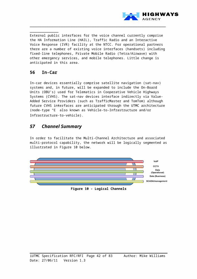
_____________________________________________________________________
73 Component Models and Protocol Bindings
Several components models have been proposed for various platforms. The most popular ones are based on the distributed object paradigm and include:
• The Microsoft DCOM model, for the Windows platform.• The Enterprise Java Beans (EJB), for the Java Enterprise platform.• The CORBA Component Model (CCM).
Within the sphere of SOA’s, the Service Component Architecture (SCA) specification has recently been introduced by major IT vendors (IBM, BEA, IONA, SAP, Oracle, etc.).
Figure 21 - The SCA Component Model
The most significant feature of the SCA model shown in Figure 21 is the explicit separation of interfaces and their bindings.
Viewed from the outside, an SCA component is a simple object and has the same fundamental parts, as shown below.
iUTMC Specification RFC/RFI Page 42 of 58 Author: Mike Williams Date: 28/06/11 Version 1.3
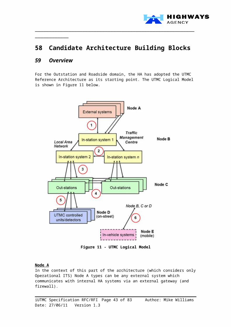
_____________________________________________________________________
Figure 22 - Component partsServices and references enable a component to communicate with other software but they do not specify HOW that communication happens - that is the job of bindings, as shown below in Figure 23.
Figure 23 – Bindings
A binding specifies precisely HOW communications are carried out between a component and another component or external entity. Depending on what it’s communicating with, a component may or may not have explicitly specified bindings. As Figure 23 shows, a component that communicates with another component in the same domain does not need to have any explicit bindings specified - the runtime environment determines the bindings to use.
iUTMC Specification RFC/RFI Page 43 of 58 Author: Mike Williams Date: 28/06/11 Version 1.3
_____________________________________________________________________To communicate outside its domain, however, one or more bindings must be specified. Each binding defines a particular protocol that can be used to communicate with this service or reference. A single reference can have multiple bindings, allowing different remote objects to communicate with it in a number of ways, e.g. DCPS/RTPS (DDS) or SOAP/HTTP (WS-*).
Since bindings separate HOW components communicate from WHAT they do, they divorce the component’s business logic from the details of underlying communication protocols. This separation of concerns make application design simpler.
References:http://en.wikipedia.orghttp://www.osoa.org Technical Framework Description – SODA, v1.0.4, Final, 1st May 2007INTRODUCING SCA, DAVID CHAPPELL JULY 2007
74 Embedded Java and OSGi
The SODA toolkits, outlined earlier in Section 70 SODA – Eclipse Project), included a ‘reference’ implementation using embedded Java™ and the OSGi framework.
The OSGi Alliance is a worldwide consortium of technology-based organisations with a process designed to assure interoperability between applications and services based on its component integration platform. The OSGi Service Platform has been delivered in many products and services and in diverse markets including the enterprise, mobile, home, automotive/telematics and consumer sectors.
The inclusion of the automotive and mobile sectors is of particular significance here since they potentially represent millions of iUTMC Node E devices in our future state, “To-Be” architecture.
The OSGi Alliance and its technology address the following challenges:
• How to assemble, maintain, repair and enhance software affordably, transparently, efficiently and reliably.
• How to create the flexibility needed to accommodate the wide range of business models used in the market today for software and services, and enable new and profitable business models for the future.
Figure 24 - OSGi and its technology
iUTMC Specification RFC/RFI Page 44 of 58 Author: Mike Williams Date: 28/06/11 Version 1.3
_____________________________________________________________________
The core component of the OSGi Specifications is the OSGi Framework (see Figure 25) which provides a standardised environment to application “bundles”.
Figure 25 - The OSGi Framework
The Framework is divided in a number of layers.
L0: Execution Environment L1: Modules L2: Life Cycle Management L3: Service Registry - a ubiquitous security system is deeply intertwined with all the
layers.
Whilst Java represents an Open Systems, multi-vendor platform there still remains the question of the equivalent on the Microsoft Windows .NET platform in order to deliver total portability. However, according to research by Escoffier [2005]:
“The results indicate that .NET lacks certain capabilities to create a similarly flexible and lightweight service platform as the OSGi framework. The inability of .NET to unload assemblies from within an application domain and the poor performance of inter-application domain communication, result in an inadequate dynamic service platform.”
References:http://en.wikipedia.orgPower Combination: SCA, OSGi and Spring, Introductory Whitepaper - http://www.osoa.orgDeveloping an OSGi-like Service Platform for .NET, Escoffier et al, 08/10/2005
iUTMC Specification RFC/RFI Page 45 of 58 Author: Mike Williams Date: 28/06/11 Version 1.3

_____________________________________________________________________
75 Device Management76 Introduction
Earlier, in this document (Section 59 Overview) we described System Management within the context of the UTMC Functional Model. There we stated that the UTMC Technical Specifications (TS003) stipulates SNMP as the preferred standard. However, we then went on to indicate that emerging requirements, such as remote firmware upload/download, remote configuration and diagnostics, may extend the need for more sophisticated protocols and methods. For example, SNMP does not readily provide for the monitoring and management of remote applications or their underlying platforms. This begs the question “where is the network’s edge?” The implication is that we need to consider devices, along with any embedded applications and platforms as integral to the network.
The Technology Policy for Network Management has yet to be drafted but the “To-Be” architecture must conform to ITIL and adopt a hierarchical approach as shown in Figure 26 below.
Figure 26 - Hierarchical Network Management (Source: Cisco)
iUTMC Specification RFC/RFI Page 46 of 58 Author: Mike Williams Date: 28/06/11 Version 1.3
_____________________________________________________________________Thus, the roadside devices in Network Management terms, reside at the Element Management Layer.
It’s perhaps worth mentioning at this point, that the NRTS service provider (GeneSYS) provides network management capabilities and that these include a SCADA domain.
There are a number of simple ON/OFF signals to be monitored in roadside cabinets and transmission station buildings – such as reporting whether a building door is open, low voltage detected or failure of the mains supply. These are generally referred to as ‘alarms’ although not all of them indicate a problem; for example, ‘generator running’ indicates normal operation following a supply failure.
It is necessary to monitor these remote alarms at the Network Operations Centre (NOC), so that appropriate action can be taken, if necessary. In some cases the reverse is also required – sending a simple ON/OFF signal back through the network to a remote site, perhaps to unlock a door or to remotely start a generator.
The hardware solution currently used is Texcel Technology’s VE5000 ‘Virtual Engineer’ module, which is specifically designed for monitoring the overall status of a remote site. One of these modules is installed in every Transmission Cabinet, ATMg Cabinet and Transmission Station site.
The VE5000 can respond to up to 64 digital inputs and can be configured, addressed and monitored via a standard Ethernet connection. The number of inputs that are connected vary from site to site, but typically only half of the inputs are used. Additional units (up to a maximum of 25) can be installed if more inputs should be required at some future time. The VE5000 can also drive up to 16 digital outputs and it is also capable of accepting up to 31 analogue inputs.
The management of remote SCADA units is handled by VSys, which is a software package specifically designed by Texcel for that purpose and is installed at the NOC and the DRC.
In the subsequent sections, we consider different aspects of device management, and discuss evolving trends from a device vendor's perspective.
References:http://www.texceltechnology.com/visionprod/vsys.html
77 Management Platforms and SNMP
An SNMP capability is considered essential to make devices manageable from standard management platforms. Such platforms have many limitations but are widely deployed for fault and performance management - e.g., HP OpenView and CA Unicenter.
Apart from providing device specific information by implementing and publishing proprietary MIB’s, an SNMP agent has to support the SNMPv2 MIB. Under system and SNMP groups, this MIB supports certain useful parameters like system description and numerous SNMP counters.
The Remote Network Monitoring (RMON) framework defined by IETF consists of a number of related standards. A probe, or a monitor, is the key element of this framework. It passively monitors the traffic, collecting statistical information about the nature of traffic, including protocol information at various layers. SNMP is used by the management stations to query the collected data.
iUTMC Specification RFC/RFI Page 47 of 58 Author: Mike Williams Date: 28/06/11 Version 1.3
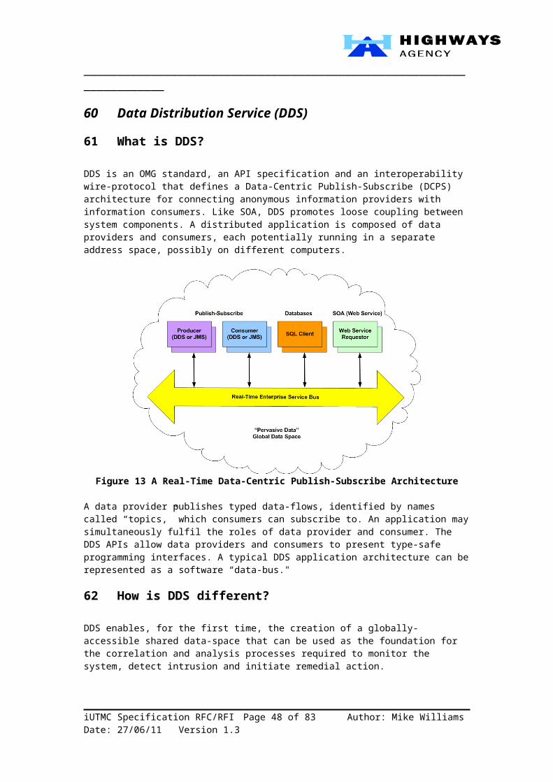
_____________________________________________________________________
78 Web Based Configuration
Web-based configuration has emerged as a necessity in recent years. With an embedded web server running on a device, configuration is more easily achieved through a standard browser-based graphical user interface.
There are many popular open source/GPL web servers available. Among them, the prominent ones are Apache and GoAhead. Apache web sever continues to be a product of choice if scalability and full functionality is required, although the GoAhead web server is considered very attractive for embedded applications, especially due to its small footprint. Mbedthis, Allegro and many other vendors have offerings that may suit specific requirements.
Standards in this arena include Web-Based Enterprise Management (WBEM) which is a set of systems management technologies developed to unify the management of distributed computing environments. WBEM is based on Internet standards and Distributed Management Task Force (DMTF) open standards: Common Information Model (CIM) infrastructure and schema, CIM-XML, CIM operations over HTTP, and WS-Management.
Key features of WBEM technology include:
Remote management of applications. Management of several instances of an application as a single unit. Standard interface for remote application management across different applications. Decoupling of application management from the client. Publishing key information about an application to other applications.
79 OSGI Remote Component Management
The OSGi Service Platform is specifically designed for devices that can operate unattended or under control of a platform operator. These are the devices that need remote management which requires bindings to a suitable communications protocol. Selecting an appropriate protocol is difficult because there are so many choices: SNMP, CMISE, CIM,OMA DM, and more.
Figure 27 - OSGi Management Protocols
iUTMC Specification RFC/RFI Page 48 of 58 Author: Mike Williams Date: 28/06/11 Version 1.3

_____________________________________________________________________
The OSGi Alliance decided that no one single management protocol can be preferred over another since “no one size fits all”. They therefore specified an architecture that provides a management API which can be used by any authorised bundle.
This is a very powerful concept that offers the same interoperability as a standard protocol. The benefit of the OSGi remote management architecture is that this provides a higher level of abstraction with respect to any given management protocol. As long as a management system can provide a standardised OSGi protocol bundle, it can operate with any manufacturer’s device, regardless of the underlying protocol.
iUTMC Specification RFC/RFI Page 49 of 58 Author: Mike Williams Date: 28/06/11 Version 1.3
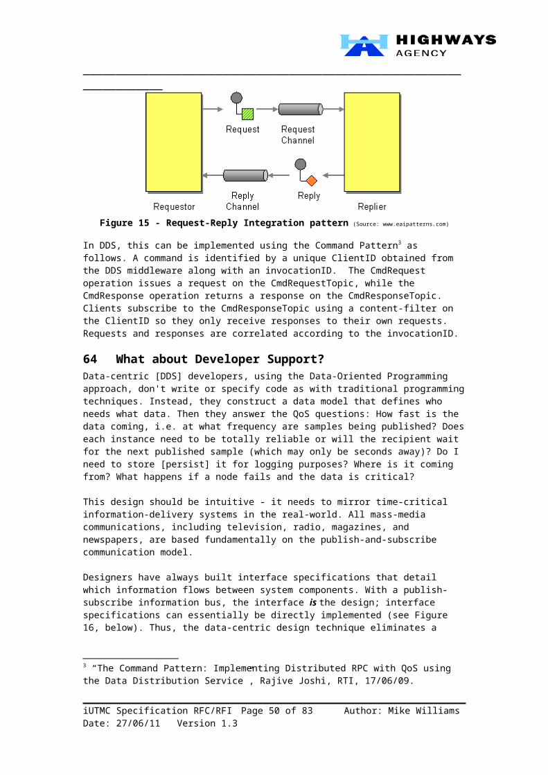
_____________________________________________________________________
80 Request for Comments and InformationThe content of this document sets out our current thinking in terms of strategic planning with a particular focus on our forthcoming Inter-Urban Transport Management and Control (iUTMC) specifications.
The aim of this endeavour is to facilitate an early engagement with our current and future supply chain partners in order to shape our technical framework for the next decade or so – a period in which there is considerable potential for growth in “Intelligent Highways” and Co-operative Vehicle Highway Systems.
We would therefore welcome your feedback, input and constructive critiques, particularly in terms of your product plans and roadmaps. Whilst we seek to influence as well as follow open, international standards, we recognise that many of you have significant R&D facilities which we simply don’t have.
This is an opportunity for you to have your say. You’re free to respond in a free format style although we’ve put together some prompts in the following questionnaire.
Should you require any further background on our Enterprise Architecture, please visit our EA pages on HA Website. Equally, if you have any questions or need to discuss the contents of this document then please write to me in the first instance at [email protected].
Mike Williams C.Eng, CITP, BA(Hons), MBA, MBCS, AIBC, FCMIEnterprise ArchitectInformation Strategy and ArchitectureHighways Agency
iUTMC Specification RFC/RFI Page 50 of 58 Author: Mike Williams Date: 28/06/11 Version 1.3

_____________________________________________________________________
Annex A – QuestionnaireThe questions below may be used to stimulate your response.
Data Distribution Service (DDS)• Do you currently support DDS?• Do you currently have clients who are using DDS:
o Within the Transport sector?o Within the Defence sector?o Other sectors?
• What do you think of DDS as:o An international standard?o A programming tool?o A real-time middleware protocol?
• Do you currently support CORBA?• Do you currently support MDA?• If so, do you see these as simplifying the transition to DDS?• Do you see DDS as a natural progression into SOA and loose-coupling?• Alternatively,
o Do you see other standards as becoming more prevalent in the near future (e.g. WS-*)? Please specify.
o Do you see a better solution to the real-time publish-subscribe requirement.• Do you have, or plan to have the required skills to implement or support DDS?• Is the lack of skills a barrier to entry?• Is there sufficient developer support, e.g. tools?• Do you have partners that are active in the DDS market? Please specify.• What is your policy on Open Source?• …
Service-Oriented Device Architectures
• Of the two standards discussed in this document, do you have a preference?o Eclipse – SODA?o ITEA/OASIS – SODDA?
• Are there other/better alternatives?• Have you implemented any yet?• Do you plan to?• Would you use the Eclipse toolkits?• Do you support the Service Component Architecture (SCA)?• What development environments do you support/prefer?• Do you support, or plan to support embedded Java?• Do you support, or plan to support the OSGi framework?• Do you agree that .NET is not a viable alternative to OSGi in this context?• Do your devices have the capability to support these embedded applications?
o Directly?o Via an adapter?
• What network management models/protocols do you support/plan to support?• …
iUTMC Specification RFC/RFI Page 51 of 58 Author: Mike Williams Date: 28/06/11 Version 1.3
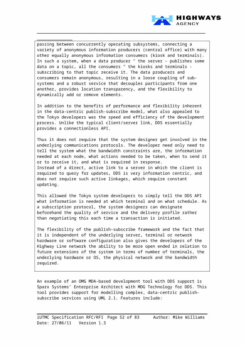
_____________________________________________________________________SUPPLEMENTARY QUESTIONS FOR SYSTEMS INTEGRATORS
TECHNOLOGY
A. In this Section we are seeking your views on designing and delivering a technology roadmap. We will use your responses to ensure we have the right approach to advancing our current capability.
A1. What are the major risks and issues to achieving an agile and scalable capability that optimises benefits; is in line with our EA principles and yet maintains delivery of our information services?
A2. How might we overcome these risks and issues?
A3. What would be a reasonable timescale and effort to deliver and migrate to this agile and scalable capability whilst maintaining our information services?
A4. Would you be able to deliver and migrate to this agile and scalable capability?
A5. What support do/could you offer for the DDS and RTPS protocol stack?
A6. Can you offer an ESB-based Abstract Endpoint container or adapter that hides the details of the DDS API from 3rd party devices?
B. In this section we are seeking your views on technological developments in capturing traffic information, its analysis and dissemination.
B1. What major developments do you anticipate in capturing traffic information over the next 2 (up to 2011), 5 and 10 years that may support our requirements?
B2. What major developments do you anticipate in traffic data processing and analysis over the next 2, 5 and10 years that may support our requirements?
EMERGING PACKAGING STRATEGY
C. In this section we are seeking your feedback on the packaging around collecting data. We will use your response to inform our approach to providing roadside maintenance and telecommunications.
C1. The supplier may be asked to deliver traffic information services for us. Would you find it acceptable for maintenance of roadside data capture equipment and telecoms services to/from the roadside to be provided by HA 3rd party suppliers? What are the risks and issues with this approach to the delivery of traffic information services and how can they be mitigated?
C2. Would you be able to provide and maintain roadside data capture equipment and telecoms services to and from the roadside? If not, would you be prepared to subcontract these services and take responsibility for their delivery? What are the risks and issues with this approach and how can they be mitigated?
iUTMC Specification RFC/RFI Page 52 of 58 Author: Mike Williams Date: 28/06/11 Version 1.3

_____________________________________________________________________C3. Are you able to provide all of the technology, either directly or through sub-
contracts? Alternatively, would you be looking for an opportunity to be a major sub-contractor or partner with another company in some kind of joint venture?
C4. Are you able to deliver elements of the technology? If so, how should we make sure they remain integrated?
TRANSITION TO AN SOA
D. In this section we are seeking your views on our transition to an SOA.
D1. What are the realistic timescales involved in transitioning to an SOA? What are challenges in delivering to these timescales and how can they be overcome?
D2. What support would you need from our current suppliers to achieve the transition, and by when?
iUTMC Specification RFC/RFI Page 53 of 58 Author: Mike Williams Date: 28/06/11 Version 1.3
_____________________________________________________________________
Annex B – CIO Memo 02/09
iUTMC Specification RFC/RFI Page 54 of 58 Author: Mike Williams Date: 28/06/11 Version 1.3

_____________________________________________________________________
Annex C – Developing a Data Exchange Architecture
iUTMC Specification RFC/RFI Page 55 of 58 Author: Mike Williams Date: 28/06/11 Version 1.3

_____________________________________________________________________
Annex D – GlossaryAirwave Secure TETRA based wireless communications for emergency services
(O2)ANPR Automatic Number Plate RecognitionAPI Application Programming Interface ATM Asynchronous Transfer Mode (Communications)BI Business IntelligenceCCTV Closed Circuit TelevisionCIO Chief Information OfficerCORBA Common Object Request Broker Architecture (OMG)COTS Commercial Off-the-shelf (products)CVHS Co-operative Vehicle Highways SystemsDATEX2 Data Exchange 2DRC Disaster Recovery CentreDSL Digital Subscriber Line (Communications)DSRC Dedicated Short Range CommunicationsEA Enterprise Architecture EARM Enterprise Architecture Reference ModelERT Emergency Response Telephonee-GIF e-Government Interoperability Frameworke-GMS e-Government metadata standardGPRS General Packet Radio ServiceGPS Geographical Positioning SystemGSM Global System for Mobile CommunicationsHA Highways AgencyHAIL Highways Agency Information Line (ID)HSDPA/HSPA+ High speed packet access (3G add-on)I2V (Road) Infrastructure to Vehicle communicationsICT Information and Communications TechnologyID Information DirectorateINSPIRE Infrastructure for Spatial Information for Europe (Directive 2007/2/EU)IP Internet Protocol (Communications)ISU Incident Support UnitITIL Information Technology Infrastructure Library (ISO 20000)ITN Integrated Transport Network ITS Intelligent Transport SystemsITS Registry ITS metadata RegistryITSS Intelligent Transport Systems and Services IVR Interactive Voice ResponseLAN Local Area Network (Communications)LCC Local Communications Controller MAC Managing Agent Contractor MIDAS Motorway Incident Detection and Automatic SignallingMosaic Unified
Operator Interface (UOI) ProjectNFR Non-functional requirementsNILO National Incident Liaison Officer (NTCC liaison with HA and MACs)NOC Network Operations CentreNRTS National Roads Telecommunications ServicesNTCC National Traffic Control CentreOBU On-Board (vehicle) UnitOGC Office of Government CommerceOGC Open Geospatial ConsortiumOGD Other Government DepartmentsOIF Operator Interface (HATMS)O&M Operational and MaintenanceOMG Object Management GroupORB Object Request Broker
iUTMC Specification RFC/RFI Page 56 of 58 Author: Mike Williams Date: 28/06/11 Version 1.3

_____________________________________________________________________OSGR Ordnance Survey Grid ReferenceOS-ITN See ITNOTAP Open Travel data Access ProtocolPFI Private Finance InitiativePIM Platform Independent Model (See MDA)POP Point of Presence (NRTS)POTI Process, Organisation, Technology and Information (MSP terminology)PPP Public Private PartnershipPSA Public Service AgreementPSM Platform Specific Model (See MDA)RACI Responsible, Accountable, Consulted, Informed (analysis)RAS Remote Access Service RCC Regional Control CentreRDS-TMC Radio Data System – Traffic Message ChannelRIF Roads Information FrameworkRMC Regional Maintenance ContractorROI Return on InvestmentROSATTE Road Safety Attributes exchange infrastructure in Europe (EC)RSS Really Simple Syndication RSU Roadside UnitSC11 NRTS Service Category 11 – Special IP for ERTs using VoIPSCADA Supervisory Control And Data Acquisition SDH Synchronous Digital Hierarchy (Communications)SDS Short Data Service (Airwave equivalent of GSM SMS text message)SMS Short Messaging Service (GSM Communications)SNMP Simple Network Management ProtocolSOA Services Oriented ArchitectureSODA Services Oriented Device [and Delivery] ArchitectureSRN Strategic Road NetworkSSO Single sign onTechMAC Technology Maintaining Agent Contractor TETRA Trans-European Trunked Radio (e.g. Airwave)TfL Transport for LondonTI 2011+ Traffic Information for 2011 and beyondTIH Travel Information Highway TMA Traffic Management ActTMC Traffic Management CentreTMS HA Traffic Management Systems (or Support) TMSP Technology Maintenance Service ProviderTMU Traffic monitoring Unit (NTCC)TOGAF The Open Group Architecture FrameworkTOS Traffic Officer ServiceTPEG Transport Protocols Expert Group (Human readable protocol)TPEG Loc International standard for location (Lat + Long + local descriptor)TPMS Technology Performance Management System (NOMAD with Halogen
and NFDB) (HATMS)TPR Transponder (HATMS)TRUE Trusted, Reliable, Useful, EffectiveTTD Traffic Technology Division (NOD)TTG Traffic Technology Groups – National and Regional (TTD)TTVMS Travel time messages on VMSUDP User Diagram ProtocolUML Unified Modelling LanguageUrNM Unified road Network Model (previously just UNM)UOI Unified Operator Interface (Mosaic)URI Universal Resource Identifier (Global naming scheme; URLs are a sub-
set)UTC Universal Time Co-ordinatedUTC Urban Traffic Control
iUTMC Specification RFC/RFI Page 57 of 58 Author: Mike Williams Date: 28/06/11 Version 1.3
_____________________________________________________________________UTMC Urban Traffic Management and ControlUWB Ultra Wideband (wireless comms)V2I Vehicle to (road) infrastructure communicationsVASP Value Added Service ProvidersVIH Video Information Highway VOIP Voice over IP WiFi IEEE 802.11 standard for wireless InternetWiMax IEEE 802.15 (Fixed WiMax) and IEEE 802.16 (Mobile WiMax) standards
for Wireless Metropolitan Access Network (MAN)XMI XML Metadata InterchangeXML Extensible mark-up languageZigBee Radio comms standard for industrial control
iUTMC Specification RFC/RFI Page 58 of 58 Author: Mike Williams Date: 28/06/11 Version 1.3