inertia-i2000 ewis panel - firesense · inertia-i2000 ewis panel operators manual revision 3.01...
TRANSCRIPT

INERTIA-I2000EWIS Panel
OPERATORS MANUAL
Revision 3.01
Manufactured by:
Approvals:Australian Standard AS2220.1ActivFire Listing No: AFP-1122
Distributors For:51/9 Hoyle AvenueCastle Hill NSW 2154Australia
telephone 02 8850 2888fax 02 8850 2999
Firesense Pty Ltd as trustee for Firesense Trust ABN 11 720 788 915
INERTIA I2000 Operator's Manual Document: I2000 OP-MAN-3.01
Page ii 15 June 2005 Issue 3.01
NON-DISCLOSURE AGREEMENT
Notifier Inertia Fire Systems (THE COMPANY) and the User of this/these document(s) desire toshare proprietary technical information concerning electronic systems.
For this reason, the company is disclosing to the User information in the form of this/thesedocument(s). In as much as the company considers this information to be proprietary and desiresthat it be maintained in confidence, it is hereby agreed by the User that such information shall bemaintained in confidence by the User for a period of TEN YEARS after the issue date and only beused for the purpose for which it was supplied.
During this period, the User shall not divulge such information to any third party without the priorwritten consent of the company and shall take reasonable efforts to prevent any unauthoriseddisclosure by its employees. However, the User shall not be required to keep such information inconfidence if it was in their possession prior to its receipt from the company; if it is or becomes publicknowledge without the fault of the User; or the information becomes available on an unrestrictedbasis from a third party having a legal right to disclose such information.
The User's receipt and retention of this information constitutes acceptance of these terms.
This information is copyright and shall not be reproduced in any form whatsoever.
AS3548 NOTICE
WARNING: "This is a Class A product. In a domestic environment this product may cause radiointerference in which case the user may be required to take
adequate measures".
Page iii 15 June 2005 Issue 3.01
TABLE OF CONTENTS
NON-DISCLOSURE AGREEMENT ....................................................................................... II
AS3548 NOTICE................................................................................................................... II
TABLE OF CONTENTS........................................................................................................III
END USER LIABILITY DISCLAIMER .................................................................................... V
AMENDMENT LOG..............................................................................................................VI
1 INTRODUCTION ...........................................................................1-1
1.1 USING THIS MANUAL............................................................................................ 1-2
1.2 ASSOCIATED DOCUMENTATION......................................................................... 1-3
1.3 STANDARD RELATED........................................................................................... 1-3
1.4 TERMINOLOGY ..................................................................................................... 1-4
2 SYSTEM DESCRIPTION..............................................................2-1
2.1 GENERAL .............................................................................................................. 2-3
2.2 EMERGENCY WARNING SYSTEM........................................................................ 2-3
2.3 INTERCOMMUNICATIONS SYSTEMS................................................................... 2-4
2.4 OPERATING MODES............................................................................................. 2-5
2.5 EMERGENCY CONTROL PANELS........................................................................ 2-5
2.6 MAIN EQUIPMENT RACK...................................................................................... 2-6
3 AUTO / MANUAL / ISOLATE MODES .........................................3-1
3.1 GENERAL .............................................................................................................. 3-2
3.2 AUTO MODE.......................................................................................................... 3-3
3.3 MANUAL MODE..................................................................................................... 3-3
3.4 ISOLATE MODE..................................................................................................... 3-3
3.5 AUTOMATIC CASCADE SEQUENCE .................................................................... 3-4
4 MASTER MODULE FUNCTIONS.................................................4-1
4.1 KEYSWITCH.......................................................................................................... 4-2
INERTIA I2000 Operator's Manual Document: I2000 OP-MAN-3.01
Page iv 15 June 2005 Issue 3.01
4.2 SYSTEM INDICATORS .......................................................................................... 4-2
4.3 COMMON INDICATORS / SWITCHES ................................................................... 4-3
4.4 AUTO/MANUAL/ISOLATE LEDS ........................................................................... 4-4
5 ZONE FUNCTION KEYS ..............................................................5-1
5.1 GENERAL .............................................................................................................. 5-2
5.2 ALL, GROUP & PROGRAM KEYS ......................................................................... 5-4
5.3 INDIVIDUAL ZONE KEYS....................................................................................... 5-7
6 FAULT / ALARM INDICATORS....................................................6-1
6.1 GENERAL .............................................................................................................. 6-2
6.2 LINE FAULT INDICATORS..................................................................................... 6-3
6.3 SYSTEM FAULT INDICATORS .............................................................................. 6-3
6.4 CLEARING LATCHED FAULTS/ALARMS............................................................. 6-6
6.5 ISOLATED ZONES................................................................................................. 6-6
6.6 SYSTEM FAULT LED............................................................................................. 6-6
7 COMMISSIONING CHECKLIST...................................................7-1
7.1 CHECKLIST ........................................................................................................... 7-2
8 SYSTEM MAINTENANCE ............................................................8-1
8.1 MONTHLY TESTING.............................................................................................. 8-2
8.2 SIX MONTHLY TESTING ....................................................................................... 8-3
8.3 YEARLY TESTING................................................................................................. 8-3
APPENDIX A .......................................................................................................A-1

Document: I2000 OP-MAN-3.01 INERTIA I2000 Operator's Manual
Issue 3.01 15 June 2005 Page v
END USER LIABILITY DISCLAIMER
The INERTIA I2000 Emergency Warning and Intercommunications Panel provides aconfiguration programming facility which may be accessed via the front panel keyboard.
Because this programming facility allows the user to define the operation of the INERTIAI2000 System, changes can be made by the user that prevent this installation from meetingstatutory requirements.
INERTIA Fire Systems, therefore cannot accept any responsibility as to the suitability of thefunctions defined by the user using the programming facility.
INERTIA I2000 Operator's Manual Document: I2000 OP-MAN-3.01
Page vi 15 June 2005 Issue 3.01
AMENDMENT LOG
September 1990 Issue 1 Original
October 2000 Issue 1.60 Deleted Chapter 7 (Programming).Added fault information for ECM networkedsystems,
August 2004 Issue 3.00 Re Printed
December 2004 Issue 3.10 Minor Updates
June 2005 Issue 3.01 Corrected Version number from V3.10 to 3.01Minor formatting changes

Page 1-1 15 June 2005 Issue 3.01
1 INTRODUCTION
INERTIA I2000 Operator's Manual Document: I2000 OP-MAN-3.01
Page 1-2 15 June 2005 Issue 3.01
1.1 USING THIS MANUAL
This Manual provides operator information on the INERTIA I2000 EWIS Panel to allow theoperator to manually control and program the operation of the system.
The Manual is structured as follows:
Chapter 1, Introduction, describes the manual, explains the format and terminology usedand lists associated INERTIA I2000 product manuals.
Chapter 2, System Description, provides an overview of the physical and operationalconcepts of the INERTIA I2000 system.
Chapter 3, Auto/Manual/Isolate Modes, describes the Auto, Manual and Isolate modes ofoperation as controlled by the key-switch. The automatic cascade sequence is alsodescribed.
Chapter 4, Master Module Functions, provides a description of the operator controls onthe master display/keyboard module.
Chapter 5, Zone Function Keys, describes the operation of the controls and indications ofthe zone display/keyboard modules.
Chapter 6, Fault Indicators, describes the various fault indications and the action theoperator should carry out in the event of a fault occurring.
Chapter 7, Placing Into Operation, provides a set by step procedure for the operator tocarry out an initial run up of a new system.
Chapter 8, Maintenance, provides step by step maintenance procedures that should becarried out at various time intervals.
Appendix A, Contract And System Details, contains charts for the recording of the contract,system and installation details along with the on-site programmed values.
Document: I2000 OP-MAN-3.01 INERTIA I2000 Operator's Manual
Issue 3.01 15 June 2005 Page 1-3
1.2 ASSOCIATED DOCUMENTATION
1.2.1 PRODUCT RELATED
The following INERTIA I2000 product manuals are available:
LT0087 INERTIA I2000 Operator's Manual, provides a complete guide to theoperation, programming and maintenance of the INERTIA I2000 EWISpanel, according to Australian Standards AS2220 Part 1. This manualis provided as standard with INERTIA I2000 EWIS panels.
LT0088 INERTIA I2000 Installation and Commissioning Manual, providescomplete details for correctly installing and placing into operation theINERTIA I2000 system.
1.3 STANDARD RELATED
AS2220.1 Emergency warning and intercommunications systems in buildings.Part 1 - Equipment design and manufacture.
AS2220.2 Emergency warning and intercommunications systems in buildings.Part 2 - System design, installation and commissioning.
AS1603.4 Automatic Fire Detection and Alarm SystemsPart 4 - Control and Indicating Equipment
AS1670.1 Automatic Fire Detection and Alarm Systems -System Design, Installation, and Commissioning.
AS1851.10 Maintenance of fire protection equipment.Part 10 - Emergency warning and intercommunications systems.
INERTIA I2000 Operator's Manual Document: I2000 OP-MAN-3.01
Page 1-4 15 June 2005 Issue 3.01
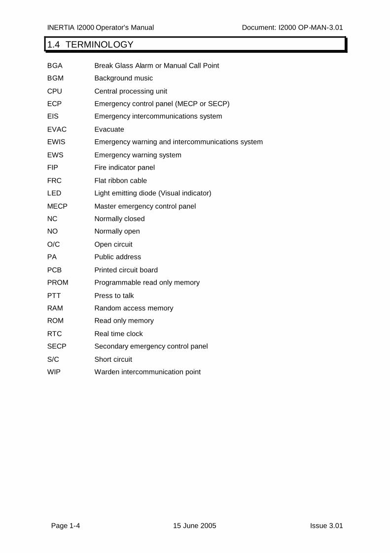
1.4 TERMINOLOGY
BGA Break Glass Alarm or Manual Call Point
BGM Background music
CPU Central processing unit
ECP Emergency control panel (MECP or SECP)
EIS Emergency intercommunications system
EVAC Evacuate
EWIS Emergency warning and intercommunications system
EWS Emergency warning system
FIP Fire indicator panel
FRC Flat ribbon cable
LED Light emitting diode (Visual indicator)
MECP Master emergency control panel
NC Normally closed
NO Normally open
O/C Open circuit
PA Public address
PCB Printed circuit board
PROM Programmable read only memory
PTT Press to talk
RAM Random access memory
ROM Read only memory
RTC Real time clock
SECP Secondary emergency control panel
S/C Short circuit
WIP Warden intercommunication point
Page 2-1 15 June 2005 Issue 3.01
2 SYSTEM DESCRIPTION
INERTIA I2000 Operator's Manual Document: I2000 OP-MAN-3.01
Page 2-2 15 June 2005 Issue 3.01
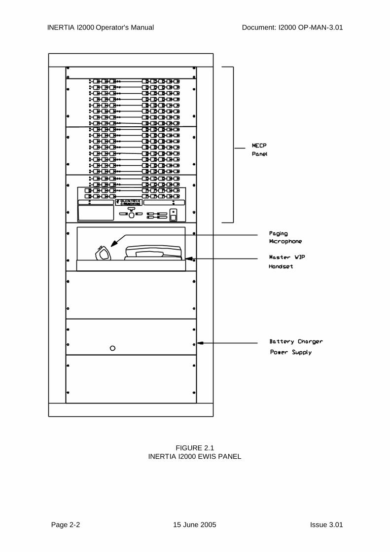
FIGURE 2.1INERTIA I2000 EWIS PANEL
Document: I2000 OP-MAN-3.01 INERTIA I2000 Operator's Manual
Issue 3.01 15 June 2005 Page 2-3
2.1 GENERAL
The purpose of an emergency warning and intercommunication system (EWIS)is to enable the orderly evacuation of a building in the event of an emergency.
The INERTIA I2000 EWIS panel achieves this by providing the following facilities in anintegrated and flexible system which complies with the Australian Standard AS2220.1:1989.
i) An Emergency Warning and Evacuation Systemii) An Intercommunication Systemiii) Automatic Evacuation Mode.
A typical INERTIA I2000 EWIS front panel layout is shown in Fig 2.1.
2.2 EMERGENCY WARNING SYSTEM
The Emergency Warning ( Evacuation ) System generates audible and/or visible signals to:
i) alert the occupants of an emergency situationii) instruct the occupants to evacuate the building.
The building is divided up into evacuation areas or zones, with at least one zone per floor of abuilding.
Zones may be selected independently, in groups, or all together for one of three independentwarning signals.
These are, in increasing priority:
1) ALERT A pulsed on/off tone of 420Hz that rises in volume through sixlevels after its initial activation. This alerts the occupants to theexistence of an emergency situation and that they shouldstandby for the evacuation tone or verbal instructions. It alsoserves to alert the floor wardens to take up their designatedpositions and prepare for evacuation.
2) EVACUATE A burst of tone rising in frequency from 500Hz to 1200Hz. After4 bursts a digitally recorded voice message is spoken twice.This pattern repeats and is the instruction for the occupants toleave the building. In the manual mode of operation the voicemessage is not included in the evacuate tone.
3) PAGING Voice announcements can be made manually from the frontpanel mounted microphone.
Visible warning lights, used to supplement the audible tones, are coloured amber for alert andred for evacuate. They can be used in areas where the background noise level is high orwhen deaf or impaired hearing people may be present.
INERTIA I2000 Operator's Manual Document: I2000 OP-MAN-3.01
Page 2-4 15 June 2005 Issue 3.01
The EWS system includes equipment to monitor the wiring cables to speakers, visiblewarning lights, etc and will indicate when a fault condition is found.
The EWS system may also be used as a paging and/or background music system under non-emergency conditions. If an alarm or a mains power supply failure occurs then thesefunctions are disabled until the cause is removed.
2.3 INTERCOMMUNICATIONS SYSTEMS
The intercommunications system allows the House Warden to communicate via telephonetype handsets to Zone or Floor Wardens located at exit points on each floor or zone. Thesystem comprises the master phone, zone selection switches and slave handsets on eachzone of the building.
Facilities are provided on the ECP to monitor the status of all calls including the reception,origination and progress of all incoming and outgoing calls as well as fault monitoring of theWIP lines.
LED indicators mounted on the ECP display the operational status of each zone and, inconjunction with an internal fault sounder, are used to alert the operator to any abnormalconditions.
The INERTIA I2000 intercommunications system is available in 1 WIP per zone or 3 WIP perzone configurations. The keyboard/display units are different for these configurations andreflect the number of WIPs per zone on the keyboard. On 3 WIP/zone systems the 3 WIPscan be called, answered and fault monitored on an individual basis.
- W A R N I N G -
Do not manually operate the hook switch of any WIP or ECP phone while holding theearpiece close to your ear. Always replace the handset to operate the hook switch. Somemakes/models/configurations of WIP phones use the earpiece to generate the ring sound andthis may be uncomfortably loud if it is close to your ear.
Document: I2000 OP-MAN-3.01 INERTIA I2000 Operator's Manual
Issue 3.01 15 June 2005 Page 2-5
2.4 OPERATING MODES
The EWIS system can be operated in any one of three modes, AUTO, MANUAL or ISOLATE.The system is normally operated in the AUTO mode. In this mode the system is connected tothe Fire Indicator Panel enabling automatic operation of the evacuation system in the event ofa fire alarm. In addition, Break Glass Alarm (BGA) manual call points can also be connectedto the EWIS system to initiate automatic operation in the event of an emergency alarm.
The system continually monitors the FIP and BGA inputs for an alarm signal. On detection ofan alarm signal, the system will generate an ALERT tone for a pre-set time. When this timeperiod has expired, it will automatically switch-over to a continuous EVACUATE toneinterspersed with a digitised voice message, advising occupants to evacuate the building.The system also provides a cascading feature for multi-storey buildings.
When the first zone changes to the evacuate tone, two zones above and one below areplaced in the alert mode. After a second time delay, these zones are placed in evacuate anda further two zones above and 1 below are placed in alert. This process cascades throughthe building, with a repetition of the second time delay, until all zones are in evacuate. Boththe "initial alarm zone ALERT ON delay" and the "cascade zone ALERT ON delay" are on-siteprogrammable. The cascade strategy can be specifically configured, during manufacture, tomeet the particular building or regulatory requirements.
In MANUAL mode the operator at the ECP has control of the system and can manually selectthe alert, evacuate or public address functions for each of the zones.
In ISOLATE mode the keyboard of the ECP is effectively isolated from the rest of the systemso that operator training can be carried out without activating the various tones in each zone.The system is still operational in that field faults or FIP/BGA activations will be shown on theirrespective indicators on the keyboard.
2.5 EMERGENCY CONTROL PANELS
The Master Emergency Control Panel (MECP) contains all the controls, status indicators,microphone and handset for the complete operation of the system.
The MECP is usually installed in a convenient, safe and quiet location to enable authorisedpersonnel to control the system in the event of an emergency. This facility can be an integralpart of the Main Equipment Rack or it can be remote. When installed remotely, the MECP isconnected to the Main Equipment Rack by a serial data communication link.
Additional Secondary Emergency Control Panels (SECP) can be similarly connected to theMain Equipment Rack for increased operational flexibility. These units are assigned a lowerpriority to the MECP so that the MECP can always take manual control and override anSECP.

INERTIA I2000 Operator's Manual Document: I2000 OP-MAN-3.01
Page 2-6 15 June 2005 Issue 3.01
2.6 MAIN EQUIPMENT RACK
The Main Equipment Rack houses the electronic equipment necessary for the generation ofthe tones, flashing lights, WIP intercommunications, FIP/BGA inputs and other ancillaryequipment.
The equipment is laid out in a modular fashion, allowing flexible configuration and systemsizes of up to 100 zones to be achieved. The primary variation between systems of differentsizes is the cabinet size, the number of modules fitted and the power supply capacity.
The system has an associated standby battery supply which is usually contained in theequipment cubicle. In the event of failure of the 240V mains electricity supply the EWISsystem will automatically be powered from its standby battery.
Page 3-1 15 June 2005 Issue 3.01
3 AUTO / MANUAL / ISOLATE MODES
INERTIA I2000 Operator's Manual Document: I2000 OP-MAN-3.01
Page 3-2 15 June 2005 Issue 3.01
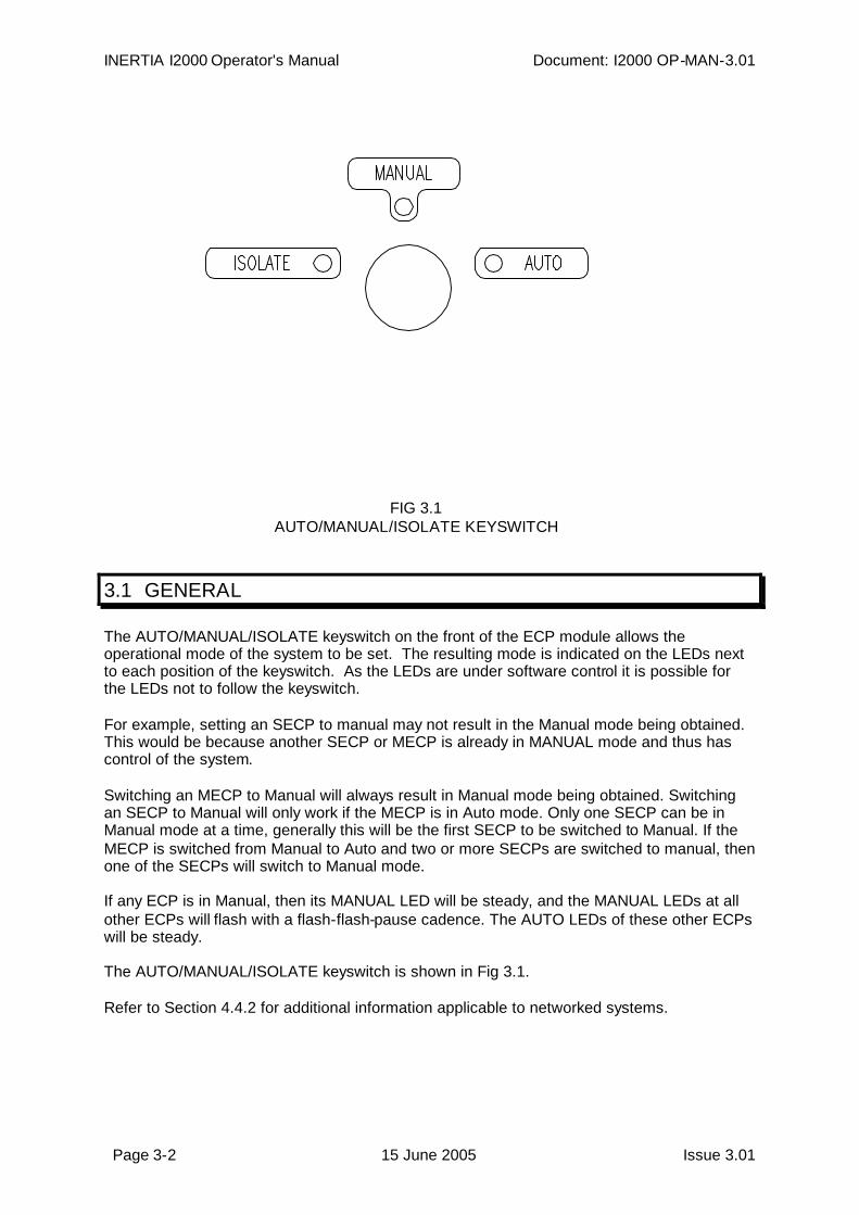
FIG 3.1AUTO/MANUAL/ISOLATE KEYSWITCH
3.1 GENERAL
The AUTO/MANUAL/ISOLATE keyswitch on the front of the ECP module allows theoperational mode of the system to be set. The resulting mode is indicated on the LEDs nextto each position of the keyswitch. As the LEDs are under software control it is possible forthe LEDs not to follow the keyswitch.
For example, setting an SECP to manual may not result in the Manual mode being obtained.This would be because another SECP or MECP is already in MANUAL mode and thus hascontrol of the system.
Switching an MECP to Manual will always result in Manual mode being obtained. Switchingan SECP to Manual will only work if the MECP is in Auto mode. Only one SECP can be inManual mode at a time, generally this will be the first SECP to be switched to Manual. If theMECP is switched from Manual to Auto and two or more SECPs are switched to manual, thenone of the SECPs will switch to Manual mode.
If any ECP is in Manual, then its MANUAL LED will be steady, and the MANUAL LEDs at allother ECPs will flash with a flash-flash-pause cadence. The AUTO LEDs of these other ECPswill be steady.
The AUTO/MANUAL/ISOLATE keyswitch is shown in Fig 3.1.
Refer to Section 4.4.2 for additional information applicable to networked systems.
Document: I2000 OP-MAN-3.01 INERTIA I2000 Operator's Manual
Issue 3.01 15 June 2005 Page 3-3
3.2 AUTO MODE
The AUTO mode is the standard operating position, whereby the Evacuation System is readyto carry out its principle function, i.e. automatic evacuation of the building in the event ofalarm. The way in which the EWIS carries out the evacuation is dependent on the cascadesequence programmed during manufacture and the on-site programmed parameters. Theautomatic cascade sequence is described in Section 3.5.
Also while in AUTO mode control is allowed to be passed to any ECP that may be requestingManual mode. If all ECPs are in AUTO then the controlling ECP will enable the automaticgeneration of alert and evacuate tones throughout the building if an alarm is detected. If anyECP is in MANUAL mode then the automatic cascade operation is overridden and theoperator can manually select zone functions. Refer to Section 3.3 for the manual modedescription.
Note that after an alarm has occurred it is possible to switch an ECP to Manual, select or de-selected tones for various zones and then return to AUTO mode, whereupon the automaticcascade will continue from the new setting if there is still an active FIP or BGA input
It is therefore important that all zone FIP, BGA, Alert and Evacuate indications are clearedbefore switching to AUTO unless the cascade function is to be continued.
3.3 MANUAL MODE
When the ECP is in the MANUAL mode, all buttons on the Evacuation System keyboard areenabled except for the PROGRAM button.
This stops the automatic cascading of the alert and evacuate tones and allows the operatorto have manual control of the system. The various tones or functions can be selected foreach or all of the zones as required.
Ensure all FIP and BGA alarm conditions and all zone alert and evacuate commands havebeen removed before switching to AUTO from the MANUAL mode.
3.4 ISOLATE MODE
Switching an ECP to ISOLATE will have a different effect depending on whether the ECP isthe MECP or an SECP.
At the MECP the ISOLATE mode will cause the whole system to be isolated. I.e. alarmsoccurring on the FIP or BGA inputs will not cause zones to be placed into alert and evacuate,although the FIP and BGA LED indicators on the keyboard/display will continue to show thecorrect FIP/BGA status. Furthermore, the keyboard is isolated from the system, so that, forexample, selecting a zone for evacuate will cause the zone EVACUATE LED to turn on butno evacuate tone will be generated in the zone. However if the MECP is switched toMANUAL with zones selected, then tones will start on those zones.
Note that if an MECP is powered down when it is in ISOLATE, the SECP will not take overcontrol of the system.
Placing an SECP into ISOLATE will not affect the automatic cascade operation of the system,it will only isolate the SECP keyboard from the system. Pressing keys will light theappropriate indicators but will not result in the tones being generated in the zones. The MECPwill control the system while the SECP is in ISOLATE. If the MECP fails while the SECP is inISOLATE, the SECP will not take over control.
INERTIA I2000 Operator's Manual Document: I2000 OP-MAN-3.01
Page 3-4 15 June 2005 Issue 3.01
Switching an SECP from MANUAL to ISOLATE will result in the MECP taking control andchanging the mode of the system from MANUAL to AUTO (as the MECP must be in AUTOfor the SECP to have been in MANUAL). Ensure all FIP and BGA alarm conditions and allzone alert and evacuate commands have been removed before switching an SECP fromMANUAL to ISOLATE.
The ISOLATE mode is meant as a training position and is best performed at an SECP, ifpresent. This is because the rest of the system will then still be operational and ready to actif an alarm is detected. Note that in this situation the isolated SECP indicators will show theresult of the alarm and cascading functions.
When an SECP is switched out of ISOLATE all functions selected by the operator will beautomatically cancelled, and the MECP will then transfer to the SECP the current status ofthe system. This may take a few seconds, and during this time the SECP will not go into theMANUAL mode even though the keyswitch may be in the MANUAL position.
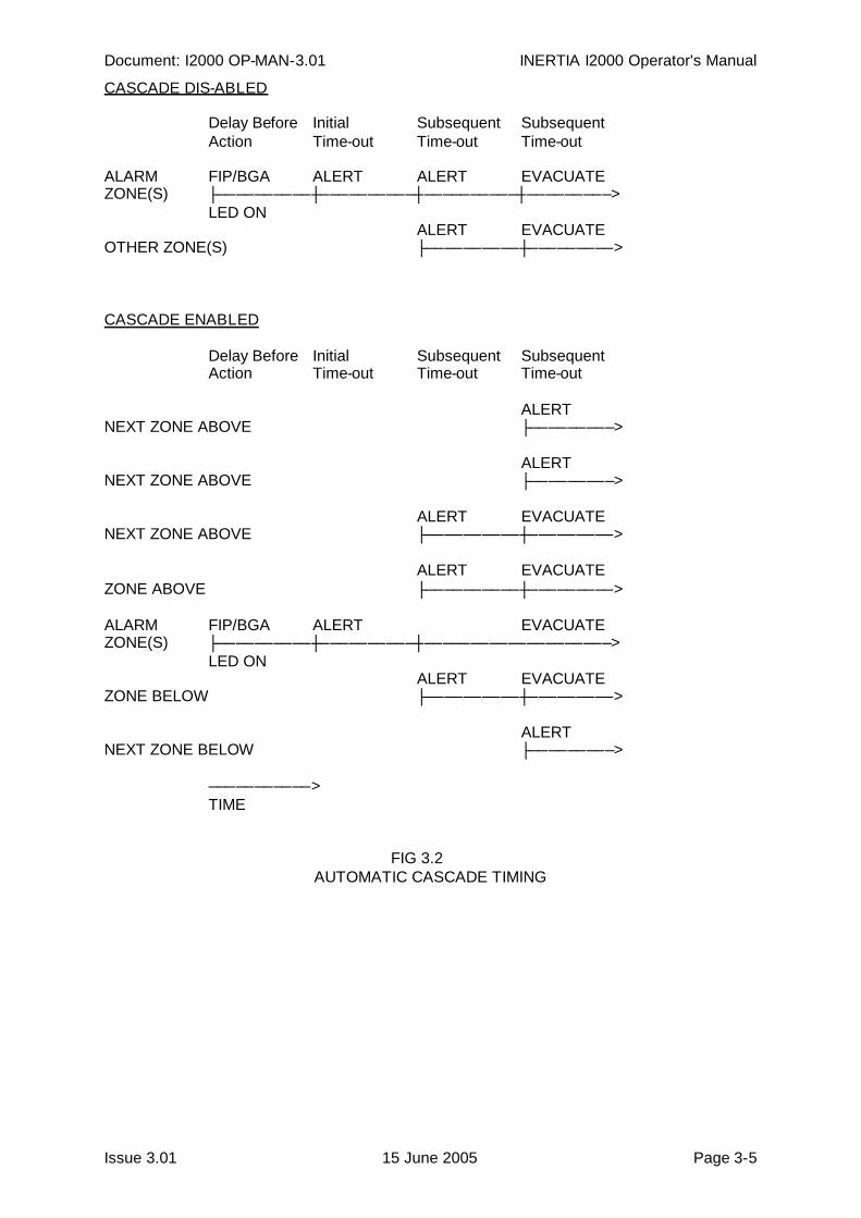
3.5 AUTOMATIC CASCADE SEQUENCE
The Automatic cascade sequence can be enabled or disabled via the on-site programmingmode described in Section 7.
When the cascade sequence is disabled the EWIS panel operates in an "all zone" modefollowing the detection of a FIP or BGA alarm. The EWIS panel will indicate the zone(s) inalarm by the appropriate FIP or BGA LED flashing, delay for the "delay before action", thenplace these zones in ALERT and delay for the duration of the "initial time-out" delay. Then allzones will be put in ALERT and the sequence will wait for the "subsequent time-out" delaybefore putting all zones into EVACUATE.
When the cascade sequence is enabled the system will automatically step through the zonesas defined by the built-in evacuation sequence. This can be custom programmed for aparticular system but the standard sequence works as follows.
Detection of alarm on a zone will place that zone into ALERT after the "delay before action"and then cause the system to wait for the "initial time-out" delay. The zone in ALERT willthen change to EVACUATE and the two zones above and one below will be put into ALERT,followed by the "subsequent time-out" delay.
At the end of this second delay those zones in ALERT will be put into EVACUATE and afurther two above and one below will be put into ALERT. This sequence repeats until allzones are in EVACUATE.
Note that the programmable time delays have different effects depending on whethercascade is enabled or disabled.
The timing diagrams for the two modes are shown in Fig 3.2.
When switching from Manual to Auto there is a 5 second delay during which no cascaderelated functions will be carried out. After powering up in Auto there is a 30 second delaybefore any cascade functions begin.
Document: I2000 OP-MAN-3.01 INERTIA I2000 Operator's Manual
Issue 3.01 15 June 2005 Page 3-5
CASCADE DIS-ABLED
Delay Before Initial Subsequent SubsequentAction Time-out Time-out Time-out
ALARM FIP/BGA ALERT ALERT EVACUATEZONE(S) ├──────────┼──────────┼──────────┼─────────>
LED ONALERT EVACUATE
OTHER ZONE(S) ├──────────┼─────────>
CASCADE ENABLED
Delay Before Initial Subsequent SubsequentAction Time-out Time-out Time-out
ALERTNEXT ZONE ABOVE ├─────────>
ALERTNEXT ZONE ABOVE ├─────────>
ALERT EVACUATENEXT ZONE ABOVE ├──────────┼─────────>
ALERT EVACUATEZONE ABOVE ├──────────┼─────────>
ALARM FIP/BGA ALERT EVACUATEZONE(S) ├──────────┼──────────┼────────────────────>
LED ONALERT EVACUATE
ZONE BELOW ├──────────┼─────────>
ALERTNEXT ZONE BELOW ├─────────>
───────────>TIME
FIG 3.2AUTOMATIC CASCADE TIMING

INERTIA I2000 Operator's Manual Document: I2000 OP-MAN-3.01
Page 3-6 15 June 2005 Issue 3.01
Page 4-1 15 June 2005 Issue 3.01
4 MASTER MODULE FUNCTIONS
INERTIA I2000 Operator's Manual Document: I2000 OP-MAN-3.01
Page 4-2 15 June 2005 Issue 3.01
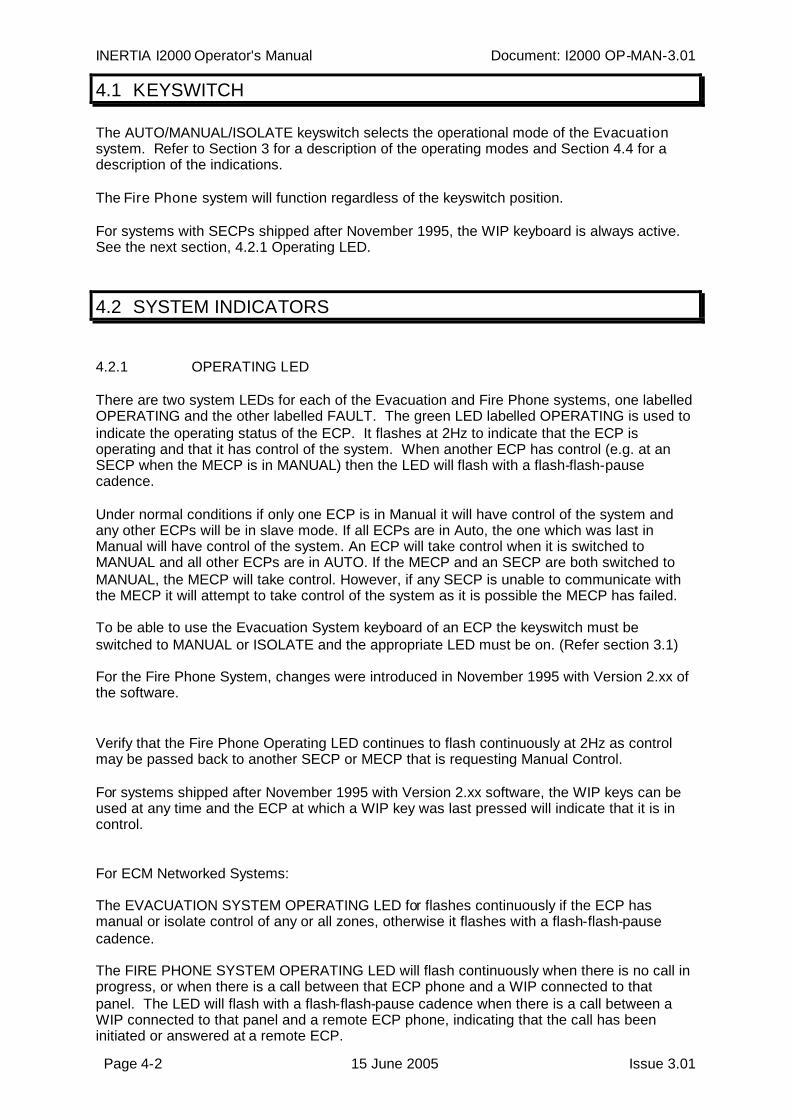
4.1 KEYSWITCH
The AUTO/MANUAL/ISOLATE keyswitch selects the operational mode of the Evacuationsystem. Refer to Section 3 for a description of the operating modes and Section 4.4 for adescription of the indications.
The Fire Phone system will function regardless of the keyswitch position.
For systems with SECPs shipped after November 1995, the WIP keyboard is always active.See the next section, 4.2.1 Operating LED.
4.2 SYSTEM INDICATORS
4.2.1 OPERATING LED
There are two system LEDs for each of the Evacuation and Fire Phone systems, one labelledOPERATING and the other labelled FAULT. The green LED labelled OPERATING is used toindicate the operating status of the ECP. It flashes at 2Hz to indicate that the ECP isoperating and that it has control of the system. When another ECP has control (e.g. at anSECP when the MECP is in MANUAL) then the LED will flash with a flash-flash-pausecadence.
Under normal conditions if only one ECP is in Manual it will have control of the system andany other ECPs will be in slave mode. If all ECPs are in Auto, the one which was last inManual will have control of the system. An ECP will take control when it is switched toMANUAL and all other ECPs are in AUTO. If the MECP and an SECP are both switched toMANUAL, the MECP will take control. However, if any SECP is unable to communicate withthe MECP it will attempt to take control of the system as it is possible the MECP has failed.
To be able to use the Evacuation System keyboard of an ECP the keyswitch must beswitched to MANUAL or ISOLATE and the appropriate LED must be on. (Refer section 3.1)
For the Fire Phone System, changes were introduced in November 1995 with Version 2.xx ofthe software.
Verify that the Fire Phone Operating LED continues to flash continuously at 2Hz as controlmay be passed back to another SECP or MECP that is requesting Manual Control.
For systems shipped after November 1995 with Version 2.xx software, the WIP keys can beused at any time and the ECP at which a WIP key was last pressed will indicate that it is incontrol.
For ECM Networked Systems:
The EVACUATION SYSTEM OPERATING LED for flashes continuously if the ECP hasmanual or isolate control of any or all zones, otherwise it flashes with a flash-flash-pausecadence.
The FIRE PHONE SYSTEM OPERATING LED will flash continuously when there is no call inprogress, or when there is a call between that ECP phone and a WIP connected to thatpanel. The LED will flash with a flash-flash-pause cadence when there is a call between aWIP connected to that panel and a remote ECP phone, indicating that the call has beeninitiated or answered at a remote ECP.
Document: I2000 OP-MAN-3.01 INERTIA I2000 Operator's Manual
Issue 3.01 15 June 2005 Page 4-3
If the OPERATING LED is permanently off, permanently on or flashing at a rate or cadencedifferent to that described above then a fault exists with the ECP module.
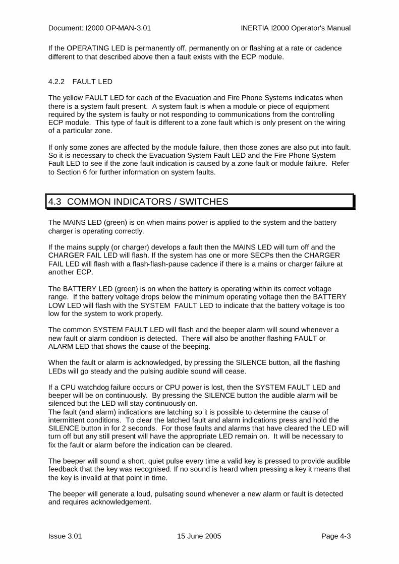
4.2.2 FAULT LED
The yellow FAULT LED for each of the Evacuation and Fire Phone Systems indicates whenthere is a system fault present. A system fault is when a module or piece of equipmentrequired by the system is faulty or not responding to communications from the controllingECP module. This type of fault is different to a zone fault which is only present on the wiringof a particular zone.
If only some zones are affected by the module failure, then those zones are also put into fault.So it is necessary to check the Evacuation System Fault LED and the Fire Phone SystemFault LED to see if the zone fault indication is caused by a zone fault or module failure. Referto Section 6 for further information on system faults.
4.3 COMMON INDICATORS / SWITCHES
The MAINS LED (green) is on when mains power is applied to the system and the batterycharger is operating correctly.
If the mains supply (or charger) develops a fault then the MAINS LED will turn off and theCHARGER FAIL LED will flash. If the system has one or more SECPs then the CHARGERFAIL LED will flash with a flash-flash-pause cadence if there is a mains or charger failure atanother ECP.
The BATTERY LED (green) is on when the battery is operating within its correct voltagerange. If the battery voltage drops below the minimum operating voltage then the BATTERYLOW LED will flash with the SYSTEM FAULT LED to indicate that the battery voltage is toolow for the system to work properly.
The common SYSTEM FAULT LED will flash and the beeper alarm will sound whenever anew fault or alarm condition is detected. There will also be another flashing FAULT orALARM LED that shows the cause of the beeping.
When the fault or alarm is acknowledged, by pressing the SILENCE button, all the flashingLEDs will go steady and the pulsing audible sound will cease.
If a CPU watchdog failure occurs or CPU power is lost, then the SYSTEM FAULT LED andbeeper will be on continuously. By pressing the SILENCE button the audible alarm will besilenced but the LED will stay continuously on.The fault (and alarm) indications are latching so it is possible to determine the cause ofintermittent conditions. To clear the latched fault and alarm indications press and hold theSILENCE button in for 2 seconds. For those faults and alarms that have cleared the LED willturn off but any still present will have the appropriate LED remain on. It will be necessary tofix the fault or alarm before the indication can be cleared.
The beeper will sound a short, quiet pulse every time a valid key is pressed to provide audiblefeedback that the key was recognised. If no sound is heard when pressing a key it means thatthe key is invalid at that point in time.
The beeper will generate a loud, pulsating sound whenever a new alarm or fault is detectedand requires acknowledgement.
INERTIA I2000 Operator's Manual Document: I2000 OP-MAN-3.01
Page 4-4 15 June 2005 Issue 3.01
The beeper will generate a loud, continuous sound if either of the CPUs on the ECP modulefail.
4.4 AUTO/MANUAL/ISOLATE LEDS
4.4.1 Non-Networked Systems
The AUTO, MANUAL, and ISOLATE LEDs normally indicate the position of the keyswitch,with the following exceptions -
The MANUAL LED may be flashing with a flash-flash-pause cadence. This indicates anotherECP has Manual control of the system.
At an SECP the keyswitch may be in the Manual position, but the AUTO LED may be on andthe Manual LED flashing. This indicates that the MECP or another SECP is switched toManual, over-riding this SECP.
At an SECP switched to Manual or Auto, the ISOLATE LED may be on. This indicates thatthe MECP (and hence the whole system) is switched to Isolate.
4.4.2 ECM Networked Systems
For ECM Networked Systems the AUTO, MANUAL, and ISOLATE LEDs on the ECP displayin various combinations to indicate various conditions:
AUTO Some or all zones are in AUTO.Steady MANUAL All zones are under manual control at this ECP.Steady ISOLATE All zones are in ISOLATE and under the control of this
ECP.Continuous flash MANUAL Some zones are under manual control at this ECP.Continuous flash ISOLATE Some zones are in ISOLATE and under the control of this
ECP.Flash-flash-pause MANUAL Some zones are in manual control of another ECP.Flash-flash-pause ISOLATE Some zones are in ISOLATE and under the control of
another ECP.
It is possible for there to be more than one LED on at a time. For example if this ECP is inAUTO but some zones are under manual control at another ECP, the AUTO LED will besteady and the MANUAL LED will be flashing with a flash-flash-pause cadence.

Page 5-1 15 June 2005 Issue 3.01
5 ZONE FUNCTION KEYS
INERTIA I2000 Operator's Manual Document: I2000 OP-MAN-3.01
Page 5-2 15 June 2005 Issue 3.01
5.1 GENERAL
The ECP must be in the MANUAL or ISOLATE modes for the Evacuation keyboard to work.The ECP keyboard contains function selection keys for each zone and also "All Zone" andprogrammable "Group" keys.
The "All Zone" keys cause all zones to be selected (or de-selected) for the appropriatefunction while the Group keys only work on the programmed group of zones.
All keys act with a toggle action, i.e. if the appropriate LED is off then pressing the key willselect the function and turn the LED on. Similarly, if the LED is on, pressing the key will de-select the function and turn the LED off. This toggle action works on the ALL and GROUPkeys as well so that a combination of single, group and all-zone functions will produce avariety of zone selections.
For example, pressing the ALL ALERT key (with the ALL ALERT LED off) will turn all zones toAlert and turn on the ALL ALERT and GROUP ALERT LEDs. Pressing individual zoneALERT keys will turn off the Alert tone to those zones while pressing the GROUP ALERT willturn off the programmed group of zones. Pressing the GROUP ALERT again will turn thegroup back to alert as the group had been turned off.
Each key press should result in a short audible beep being heard. If no beep is heard thenthis may be due to the key being invalid at the that point in time (e.g. during programming), orthe system is still trying to process the last key press, or the ECP is in Auto mode. Therefore ifkeys are pressed in quick succession, it may be noticed that the second key press has noeffect or is not beeped until sometime after pressing. This is sometimes evident on largesystems and in particular with the All and Group functions.
The Evacuation System Alert, Evacuate and PA Speech functions have an increasingprioritisation. I.e. the Evacuate tone will be generated for the zone if both the ALERT andEVACUATE LEDs are on. Similarly, if PA SPEECH is on and the Microphone PTT switch ispressed in, then speech will override any alert and evacuate tones selected.
On an ECM networked system the Alert, Evac and/or PA indicators for a zone will flash if thatzone is mapped to multiple zones at another ECP, and the Alert, Evac/PA function is on forsome but not all of the mapped zones. Do not confuse this with Zone Isolate function (notavailable on ECM networked systems) where Alert/Evac and PA will flash continuously on anisolated zone.
With networked systems, there are times when Alert/Evac/PA for some zones will not be ableto be controlled because those zones are under control by a higher priority ECP. OperatingALL or GROUP functions will not affect these zones, and the zone keys themselves will notbe able to be operated. However the zones which are controllable will operate as usual. Inthese cases (some zones uncontrollable) the Manual or Isolate LED will be flashingcontinuously indicating only partly manual or partly isolated. However the WIP controls willalways be active for all zones.
Document: I2000 OP-MAN-3.01 INERTIA I2000 Operator's Manual
Issue 3.01 15 June 2005 Page 5-3
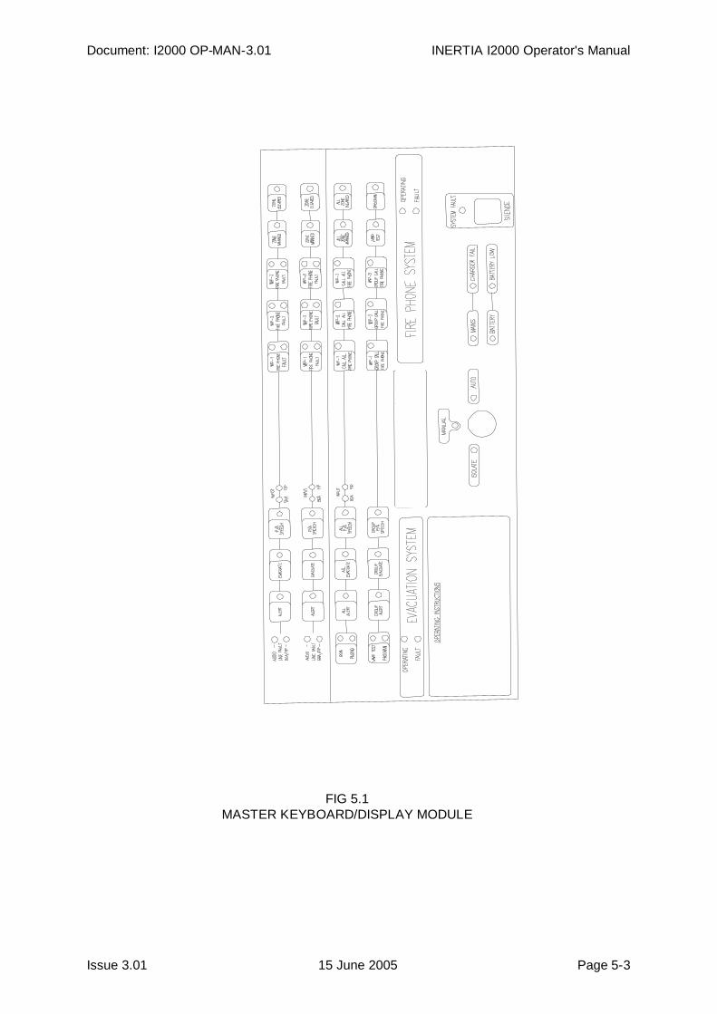
FIG 5.1MASTER KEYBOARD/DISPLAY MODULE
INERTIA I2000 Operator's Manual Document: I2000 OP-MAN-3.01
Page 5-4 15 June 2005 Issue 3.01
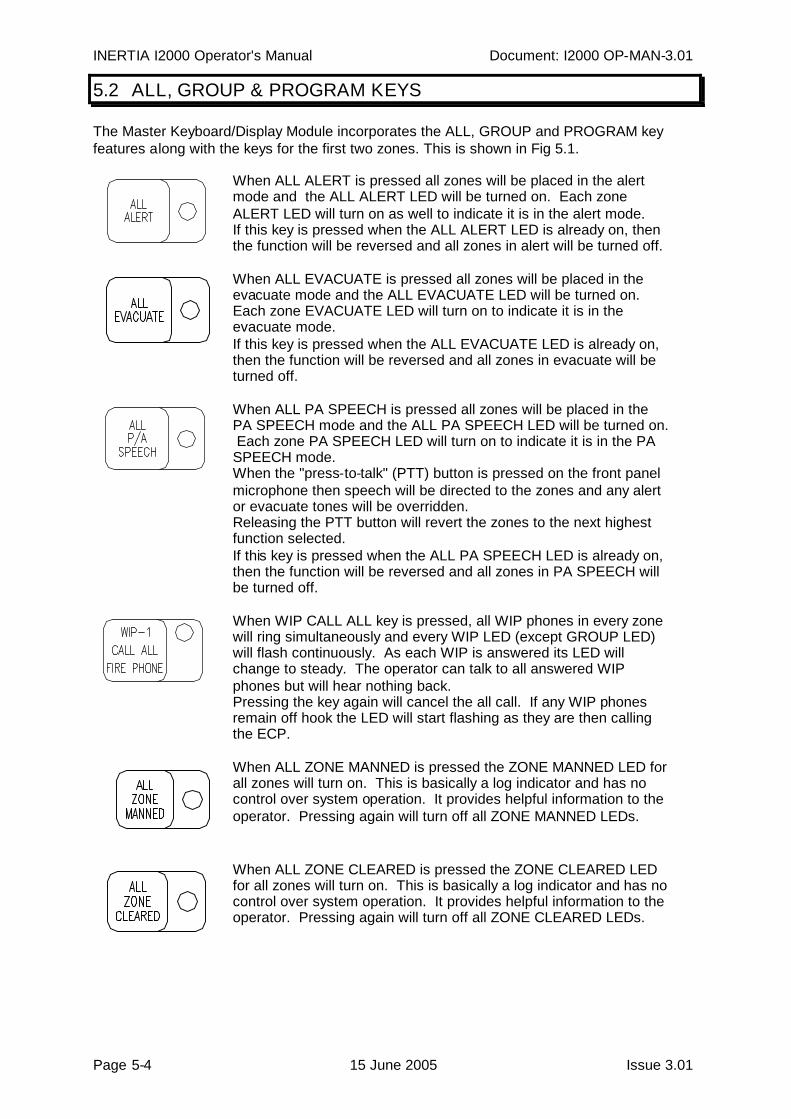
5.2 ALL, GROUP & PROGRAM KEYS
The Master Keyboard/Display Module incorporates the ALL, GROUP and PROGRAM keyfeatures along with the keys for the first two zones. This is shown in Fig 5.1.
When ALL ALERT is pressed all zones will be placed in the alertmode and the ALL ALERT LED will be turned on. Each zoneALERT LED will turn on as well to indicate it is in the alert mode.If this key is pressed when the ALL ALERT LED is already on, thenthe function will be reversed and all zones in alert will be turned off.
When ALL EVACUATE is pressed all zones will be placed in theevacuate mode and the ALL EVACUATE LED will be turned on.Each zone EVACUATE LED will turn on to indicate it is in theevacuate mode.If this key is pressed when the ALL EVACUATE LED is already on,then the function will be reversed and all zones in evacuate will beturned off.
When ALL PA SPEECH is pressed all zones will be placed in thePA SPEECH mode and the ALL PA SPEECH LED will be turned on.Each zone PA SPEECH LED will turn on to indicate it is in the PASPEECH mode.When the "press-to-talk" (PTT) button is pressed on the front panelmicrophone then speech will be directed to the zones and any alertor evacuate tones will be overridden.Releasing the PTT button will revert the zones to the next highestfunction selected.If this key is pressed when the ALL PA SPEECH LED is already on,then the function will be reversed and all zones in PA SPEECH willbe turned off.
When WIP CALL ALL key is pressed, all WIP phones in every zonewill ring simultaneously and every WIP LED (except GROUP LED)will flash continuously. As each WIP is answered its LED willchange to steady. The operator can talk to all answered WIPphones but will hear nothing back.Pressing the key again will cancel the all call. If any WIP phonesremain off hook the LED will start flashing as they are then callingthe ECP.
When ALL ZONE MANNED is pressed the ZONE MANNED LED forall zones will turn on. This is basically a log indicator and has nocontrol over system operation. It provides helpful information to theoperator. Pressing again will turn off all ZONE MANNED LEDs.
When ALL ZONE CLEARED is pressed the ZONE CLEARED LEDfor all zones will turn on. This is basically a log indicator and has nocontrol over system operation. It provides helpful information to theoperator. Pressing again will turn off all ZONE CLEARED LEDs.

Document: I2000 OP-MAN-3.01 INERTIA I2000 Operator's Manual
Issue 3.01 15 June 2005 Page 5-5
When GROUP ALERT is pressed all zones in the programmedgroup will be placed in the alert mode, their ALERT LED will turn on,and the GROUP ALERT LED will be turned on.If this key is pressed when the GROUP ALERT LED is already on,then the function will be reversed and all zones in the group in alertwill be turned off.
When GROUP EVACUATE is pressed all zones in the programmedgroup will be placed in the evacuate mode, their EVACUATE LEDwill turn on, and the GROUP EVACUATE LED will be turned on.If this key is pressed when the GROUP EVACUATE LED is alreadyon, then the function will be reversed and all zones in the group inevacuate will be turned off.
When GROUP PA SPEECH is pressed all zones in the programmedgroup will be placed in the PA SPEECH mode, their PA SPEECHLED will turn on, and the GROUP PA SPEECH LED will be turnedon.When the "press-to-talk" (PTT) button is pressed on the front panelmicrophone then speech will be directed to these zones and anyalert or evacuate tones will be overridden.Releasing the PTT button will revert the zones to the next highestfunction selected.If this key is pressed when the GROUP PA SPEECH LED is alreadyon, then the function will be reversed and all zones in the group inPA SPEECH will be turned off.
When the WIP GROUP CALL key is pressed no action will occur asthis function is currently not implemented.
While LAMP TEST is pressed in all indicators for the Fire PhoneSystem will be turned on and the fault buzzer will pulse.
When the PROGRAM key is pressed no action will occur as thisfunction is currently not implemented.
While the LAMP TEST/PROGRAM key is pressed in on theEvacuation System all indicators on the Evacuation System will beturned on and the fault buzzer will sound.
The BGM/PAGING key is used in programming mode and in faultanalysis.
When SILENCE is pressed the buzzer will be turned off if it is onand any flashing alarm or fault indicators will become steady. If it ispressed in and held for two seconds then any latched alarm or faultindicators will be cleared. The LED will remain on for any alarm orfault still present.The alarm or fault must be rectified before the LED can be turnedoff. Refer to Section 6 for more details on the alarm and faultindications.
INERTIA I2000 Operator's Manual Document: I2000 OP-MAN-3.01
Page 5-6 15 June 2005 Issue 3.01
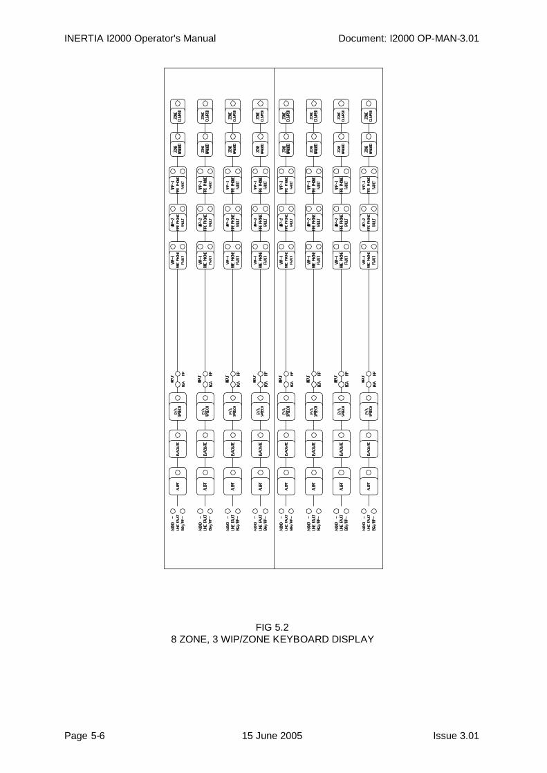
FIG 5.28 ZONE, 3 WIP/ZONE KEYBOARD DISPLAY
Document: I2000 OP-MAN-3.01 INERTIA I2000 Operator's Manual
Issue 3.01 15 June 2005 Page 5-7
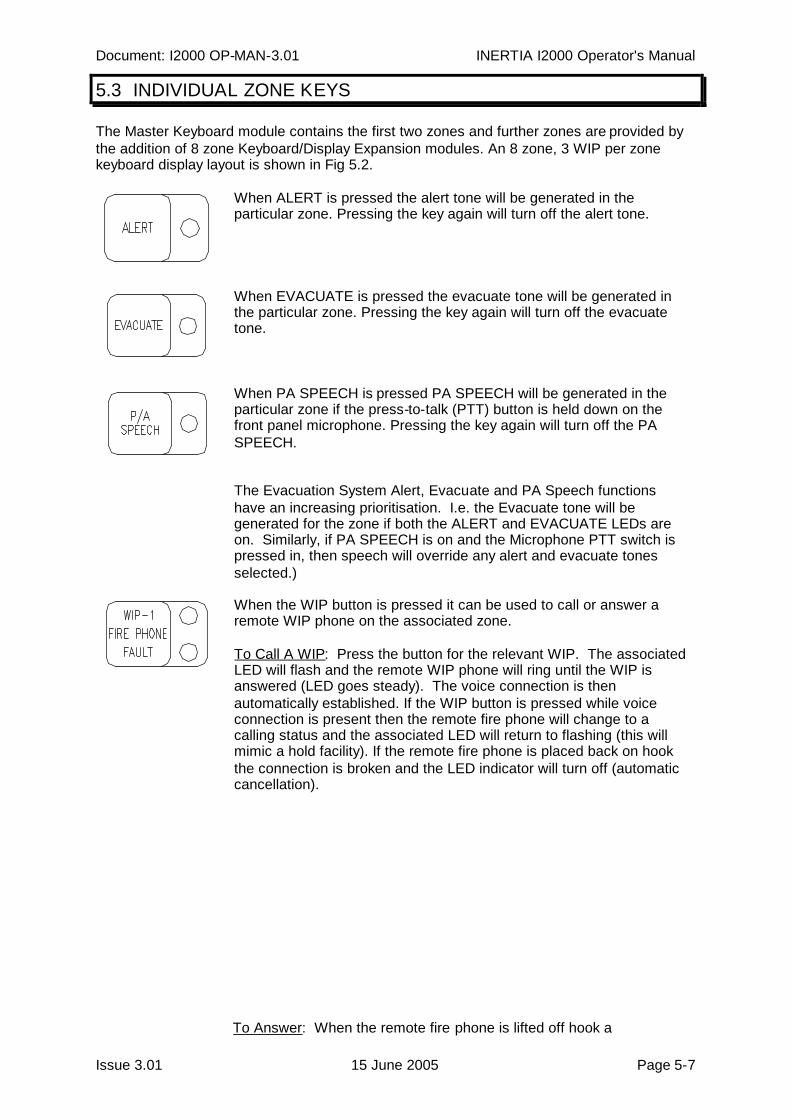
5.3 INDIVIDUAL ZONE KEYS
The Master Keyboard module contains the first two zones and further zones are provided bythe addition of 8 zone Keyboard/Display Expansion modules. An 8 zone, 3 WIP per zonekeyboard display layout is shown in Fig 5.2.
When ALERT is pressed the alert tone will be generated in theparticular zone. Pressing the key again will turn off the alert tone.
When EVACUATE is pressed the evacuate tone will be generated inthe particular zone. Pressing the key again will turn off the evacuatetone.
When PA SPEECH is pressed PA SPEECH will be generated in theparticular zone if the press-to-talk (PTT) button is held down on thefront panel microphone. Pressing the key again will turn off the PASPEECH.
The Evacuation System Alert, Evacuate and PA Speech functionshave an increasing prioritisation. I.e. the Evacuate tone will begenerated for the zone if both the ALERT and EVACUATE LEDs areon. Similarly, if PA SPEECH is on and the Microphone PTT switch ispressed in, then speech will override any alert and evacuate tonesselected.)
When the WIP button is pressed it can be used to call or answer aremote WIP phone on the associated zone.
To Call A WIP: Press the button for the relevant WIP. The associatedLED will flash and the remote WIP phone will ring until the WIP isanswered (LED goes steady). The voice connection is thenautomatically established. If the WIP button is pressed while voiceconnection is present then the remote fire phone will change to acalling status and the associated LED will return to flashing (this willmimic a hold facility). If the remote fire phone is placed back on hookthe connection is broken and the LED indicator will turn off (automaticcancellation).
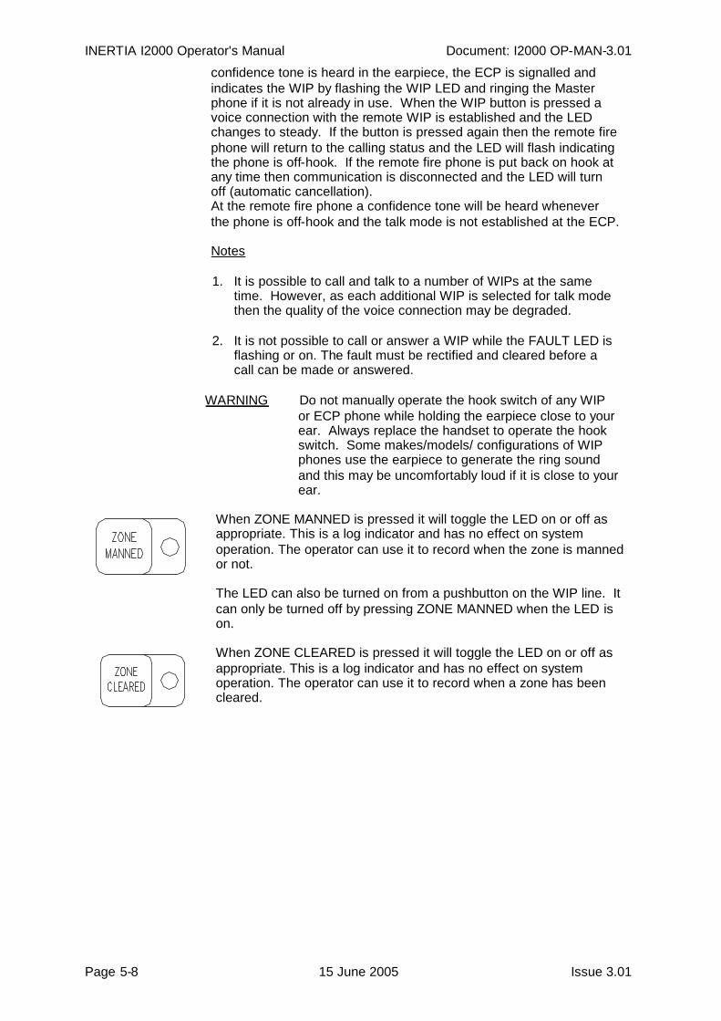
To Answer: When the remote fire phone is lifted off hook a
INERTIA I2000 Operator's Manual Document: I2000 OP-MAN-3.01
Page 5-8 15 June 2005 Issue 3.01
confidence tone is heard in the earpiece, the ECP is signalled andindicates the WIP by flashing the WIP LED and ringing the Masterphone if it is not already in use. When the WIP button is pressed avoice connection with the remote WIP is established and the LEDchanges to steady. If the button is pressed again then the remote firephone will return to the calling status and the LED will flash indicatingthe phone is off-hook. If the remote fire phone is put back on hook atany time then communication is disconnected and the LED will turnoff (automatic cancellation).At the remote fire phone a confidence tone will be heard wheneverthe phone is off-hook and the talk mode is not established at the ECP.
Notes
1. It is possible to call and talk to a number of WIPs at the sametime. However, as each additional WIP is selected for talk modethen the quality of the voice connection may be degraded.
2. It is not possible to call or answer a WIP while the FAULT LED isflashing or on. The fault must be rectified and cleared before acall can be made or answered.
WARNING Do not manually operate the hook switch of any WIPor ECP phone while holding the earpiece close to yourear. Always replace the handset to operate the hookswitch. Some makes/models/ configurations of WIPphones use the earpiece to generate the ring soundand this may be uncomfortably loud if it is close to yourear.
When ZONE MANNED is pressed it will toggle the LED on or off asappropriate. This is a log indicator and has no effect on systemoperation. The operator can use it to record when the zone is mannedor not.
The LED can also be turned on from a pushbutton on the WIP line. Itcan only be turned off by pressing ZONE MANNED when the LED ison.
When ZONE CLEARED is pressed it will toggle the LED on or off asappropriate. This is a log indicator and has no effect on systemoperation. The operator can use it to record when a zone has beencleared.
Page 6-1 15 June 2005 Issue 3.01
6 FAULT / ALARM INDICATORS
INERTIA I2000 Operator's Manual Document: I2000 OP-MAN-3.01
Page 6-2 15 June 2005 Issue 3.01
6.1 GENERAL
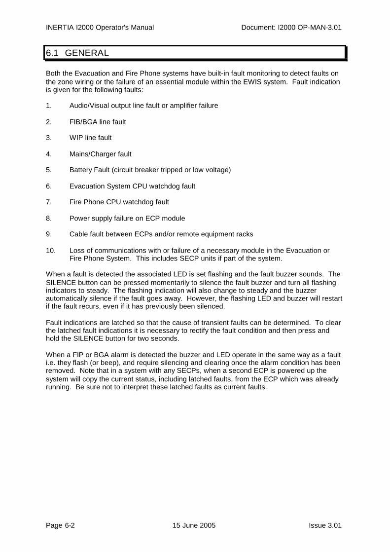
Both the Evacuation and Fire Phone systems have built-in fault monitoring to detect faults onthe zone wiring or the failure of an essential module within the EWIS system. Fault indicationis given for the following faults:
1. Audio/Visual output line fault or amplifier failure
2. FIB/BGA line fault
3. WIP line fault
4. Mains/Charger fault
5. Battery Fault (circuit breaker tripped or low voltage)
6. Evacuation System CPU watchdog fault
7. Fire Phone CPU watchdog fault
8. Power supply failure on ECP module
9. Cable fault between ECPs and/or remote equipment racks
10. Loss of communications with or failure of a necessary module in the Evacuation orFire Phone System. This includes SECP units if part of the system.
When a fault is detected the associated LED is set flashing and the fault buzzer sounds. TheSILENCE button can be pressed momentarily to silence the fault buzzer and turn all flashingindicators to steady. The flashing indication will also change to steady and the buzzerautomatically silence if the fault goes away. However, the flashing LED and buzzer will restartif the fault recurs, even if it has previously been silenced.
Fault indications are latched so that the cause of transient faults can be determined. To clearthe latched fault indications it is necessary to rectify the fault condition and then press andhold the SILENCE button for two seconds.
When a FIP or BGA alarm is detected the buzzer and LED operate in the same way as a faulti.e. they flash (or beep), and require silencing and clearing once the alarm condition has beenremoved. Note that in a system with any SECPs, when a second ECP is powered up thesystem will copy the current status, including latched faults, from the ECP which was alreadyrunning. Be sure not to interpret these latched faults as current faults.

Document: I2000 OP-MAN-3.01 INERTIA I2000 Operator's Manual
Issue 3.01 15 June 2005 Page 6-3
6.2 LINE FAULT INDICATORS
AUDIO LINE FAULT
This indicates a fault in the audio output stages of the zone amplifier or a short or open circuiton the speaker or strobe light wiring. If the fault is a strobe line fault then the Strobe MasterModule within the equipment rack will have its red fault LED flashing. (For systems with theSTRM9502 strobe relay module, its Red LED will be flashing if the fault is still present, orsteady if the fault has returned to normal. In the latter case, the red LED can be extinguishedby switching the MECP to ISOLATE and back to MANUAL or AUTO.)
If many audio line fault LEDs are on and the Evacuation System FAULT LED is also on thenthe fault is probably due to failure of the EMUX9002 or STRM9502 modules for these zones.
FIP/BGA LINE FAULT
This indicates a fault on the wiring for the FIP or BGA inputs or failure of the FIP/BGA moduleif the FIP or BGA ALARM LEDS on the "ALL" zone and the Evacuation System FAULT LEDare also on.
FIRE PHONE LINE FAULT
This indicates a fault on the wiring for the WIP line or failure of the appropriate WIPS9004module if the master module Fire Phone FAULT LED is also on.
6.3 SYSTEM FAULT INDICATORS
Loss of communication with, or failure of, one of the essential modules in the EWIS, or failureof an essential cable connecting an SECP or remote equipment rack to the MECP, will resultin flashing of the EVACUATION SYSTEM FAULT LED and/or WIP SYSTEM FAULT LED. Ifthe fault is a module fault and only some zones are affected then the fault LEDs for thosezones will also flash.
The way in which system faults are shown differs between the various software versions.Refer to the appropriate following sections.
INERTIA I2000 Operator's Manual Document: I2000 OP-MAN-3.01
Page 6-4 15 June 2005 Issue 3.01
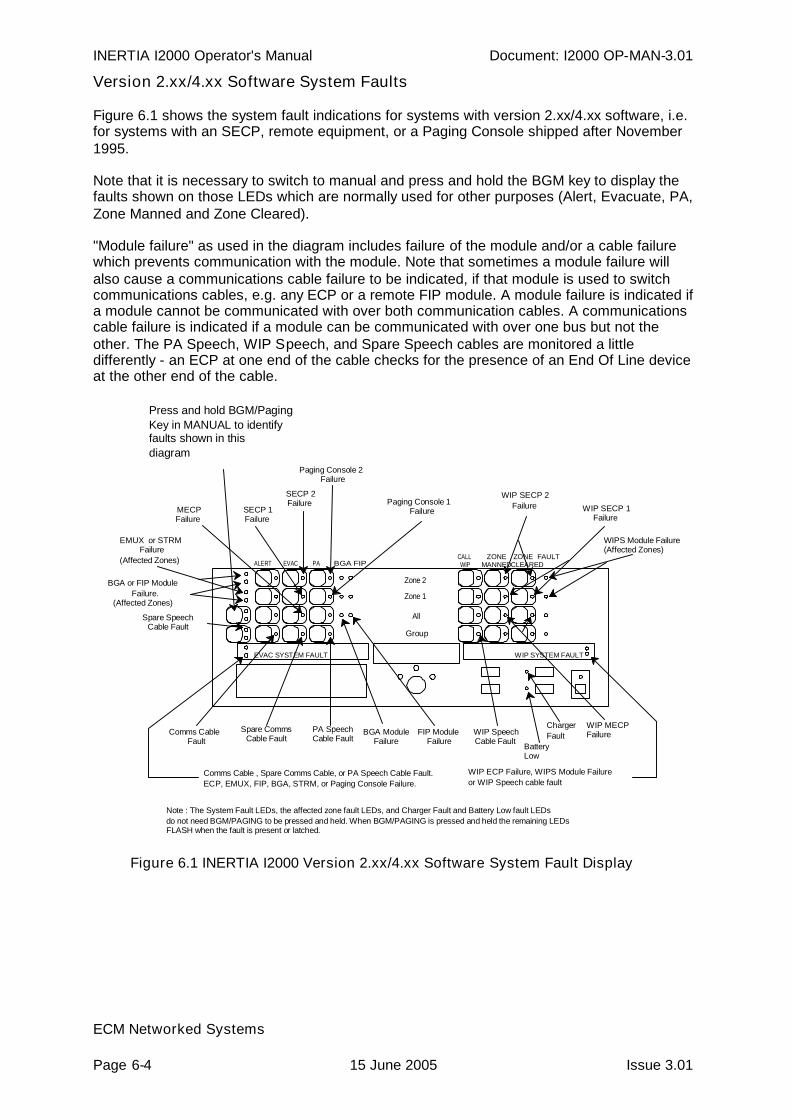
Version 2.xx/4.xx Software System Faults
Figure 6.1 shows the system fault indications for systems with version 2.xx/4.xx software, i.e.for systems with an SECP, remote equipment, or a Paging Console shipped after November1995.
Note that it is necessary to switch to manual and press and hold the BGM key to display thefaults shown on those LEDs which are normally used for other purposes (Alert, Evacuate, PA,Zone Manned and Zone Cleared).
"Module failure" as used in the diagram includes failure of the module and/or a cable failurewhich prevents communication with the module. Note that sometimes a module failure willalso cause a communications cable failure to be indicated, if that module is used to switchcommunications cables, e.g. any ECP or a remote FIP module. A module failure is indicated ifa module cannot be communicated with over both communication cables. A communicationscable failure is indicated if a module can be communicated with over one bus but not theother. The PA Speech, WIP Speech, and Spare Speech cables are monitored a littledifferently - an ECP at one end of the cable checks for the presence of an End Of Line deviceat the other end of the cable.
All
Group
Zone 1
Zone 2
ALERT EVACCALLWIP
ZONEMANNED
ZONE
EVAC SYSTEM FAULT
PA
WIPS Module Failure(Affected Zones)
PA SpeechCable Fault
BGA FIP
Paging Console 1Failure
EMUX or STRMFailure
(Affected Zones)
BGA or FIP ModuleFailure.
(Affected Zones)
WIP MECPFailure
WIP SYSTEM FAULT
Paging Console 2Failure
Note : The System Fault LEDs, the affected zone fault LEDs, and Charger Fault and Battery Low fault LEDsdo not need BGM/PAGING to be pressed and held. When BGM/PAGING is pressed and held the remaining LEDsFLASH when the fault is present or latched.
ChargerFault
BatteryLow
Spare SpeechCable Fault
WIP SECP 2Failure WIP SECP 1
Failure
CLEAREDFAULT
Press and hold BGM/PagingKey in MANUAL to identifyfaults shown in thisdiagram
Comms Cable , Spare Comms Cable, or PA Speech Cable Fault.ECP, EMUX, FIP, BGA, STRM, or Paging Console Failure.
MECPFailure
SECP 1Failure
SECP 2Failure
BGA ModuleFailure
WIP SpeechCable Fault
FIP ModuleFailure
Spare CommsCable Fault
Comms CableFault
WIP ECP Failure, WIPS Module Failureor WIP Speech cable fault
Figure 6.1 INERTIA I2000 Version 2.xx/4.xx Software System Fault Display
ECM Networked Systems
Document: I2000 OP-MAN-3.01 INERTIA I2000 Operator's Manual
Issue 3.01 15 June 2005 Page 6-5
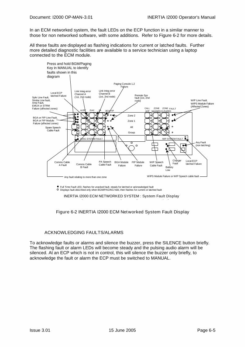
In an ECM networked system, the fault LEDs on the ECP function in a similar manner tothose for non networked software, with some additions. Refer to Figure 6-2 for more details.
All these faults are displayed as flashing indications for current or latched faults. Furthermore detailed diagnostic facilities are available to a service technician using a laptopconnected to the ECM module.
Figure 6-2 INERTIA I2000 ECM Networked System Fault Display
ACKNOWLEDGING FAULTS/ALARMS
To acknowledge faults or alarms and silence the buzzer, press the SILENCE button briefly.The flashing fault or alarm LEDs will become steady and the pulsing audio alarm will besilenced. At an ECP which is not in control, this will silence the buzzer only briefly, toacknowledge the fault or alarm the ECP must be switched to MANUAL.
All
Group
Zone 1
Zone 2
ALERT EVACCALLWIP
ZONEMANNED
ZONE
EVAC SYSTEM FAULT
PA
WIPS Module Failure(Affected Zones)
PA SpeechCable Fault
BGA FIP
WIP SYSTEM FAULT
Paging Console 1,2Failure
ChargerFault
BatteryLow
Spare SpeechCable Fault
CLEAREDFAULT
QE90 ECM Networked System : System Fault Display
Press and hold BGM/PagingKey in MANUAL to identifyfaults shown in thisdiagram
BGA ModuleFailure
WIP SpeechCable Fault
FIP ModuleFailure
Comms CableA Fault Comms Cable
B Fault
WIPS Module Failure or WIP Speech cable fault
WIP Line Fault,Spkr Line Fault,Strobe Line fault,Amp Fault,EMUX or STRMFailure (affected zones)
BGA or FIP Line Fault,BGA or FIP ModuleFailure (affected zones)
Local ECPlatched Failure
Link Integ errorChannel B(1st, 2nd node)
Link Integ errorChannel A(1st, 2nd node)
Remote Sysfault (1st, 2ndnode)
Local ECPlatched Failure
Any Fault(non latching)
Any fault relating to more than one zone
Full Time Fault LED, flashes for unacked fault, steady for latched or acknowledged faultDisplays fault described only when BGM/PAGING held, then flashes for current or latched fault
INERTIA I2000 ECM NETWORKED SYSTEM : System Fault Display
INERTIA I2000 Operator's Manual Document: I2000 OP-MAN-3.01
Page 6-6 15 June 2005 Issue 3.01
6.4 CLEARING LATCHED FAULTS/ALARMS
To clear latched fault or alarm indicators once the fault or alarm condition has been rectified,press and hold the SILENCE key for a 2 second period, with the keyswitch in the MANUAL orISOLATE position. The SYSTEM FAULT LED, the zone FAULT LEDS, and the zoneFIP/BGA ALARM LEDs should turn off.
If any faults or alarms have not been rectified then the LED will remain on indicating the faultor alarm is still present.
6.5 ISOLATED ZONES
Zones that have been isolated by the service person will be shown with the ALERT,EVACUATE and PA SPEECH LEDs all flashing together. When a zone is isolated, FIP/BGAinputs will still indicate but will not generate any fault or alarm conditions, manual controls willnot work and the automatic cascade will not generate ALERT and EVACUATE tones for thatzone. However the automatic cascade will illuminate the ALERT LED and/or the EVACUATELED for isolated zones as they are stepped over. This does not result in tones being sent tothose zones. These LEDs can be reset from the keyboard when the system is switched toMANUAL.
6.6 SYSTEM FAULT LED
The SYSTEM FAULT LED above the SILENCE button will flash and the beeper will soundwhen a fault or alarm occurs on either the EVACUATION SYSTEM or the WIP SYSTEM.When the fault or alarm is acknowledged by briefly pressing SILENCE, the beeper will stopand the LED will change to steady.
If a fault or alarm is transient, then when it goes away the beeper will stop and the LED will goout even though other acknowledged or latched faults may remain. If other unacknowledgedfaults remain, the beeper will continue sounding and the LED will continue flashing.
This LED will also go out on completion of a LAMP TEST, unless unacknowledged faultsremain present.

Page 7-1 15 June 2005 Issue 3.01
7 COMMISSIONING CHECKLIST
INERTIA I2000 Operator's Manual Document: I2000 OP-MAN-3.01
Page 7-2 15 June 2005 Issue 3.01
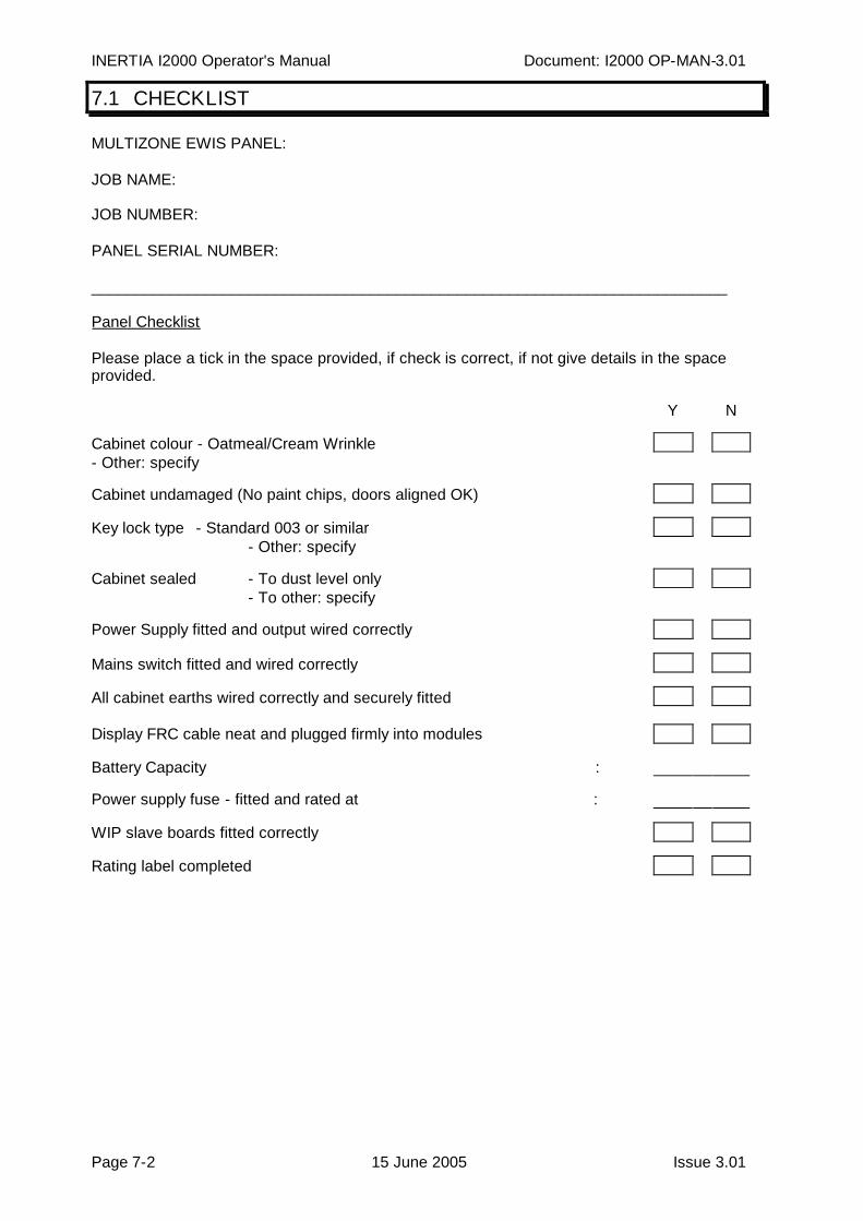
7.1 CHECKLIST
MULTIZONE EWIS PANEL:
JOB NAME:
JOB NUMBER:
PANEL SERIAL NUMBER:
_________________________________________________________________________
Panel Checklist
Please place a tick in the space provided, if check is correct, if not give details in the spaceprovided.
Y N
Cabinet colour - Oatmeal/Cream Wrinkle- Other: specify
Cabinet undamaged (No paint chips, doors aligned OK)
Key lock type - Standard 003 or similar- Other: specify
Cabinet sealed - To dust level only- To other: specify
Power Supply fitted and output wired correctly
Mains switch fitted and wired correctly
All cabinet earths wired correctly and securely fitted
Display FRC cable neat and plugged firmly into modules
Battery Capacity :
Power supply fuse - fitted and rated at :
WIP slave boards fitted correctly
Rating label completed
Document: I2000 OP-MAN-3.01 INERTIA I2000 Operator's Manual
Issue 3.10 15 June 2005 Page 7-3
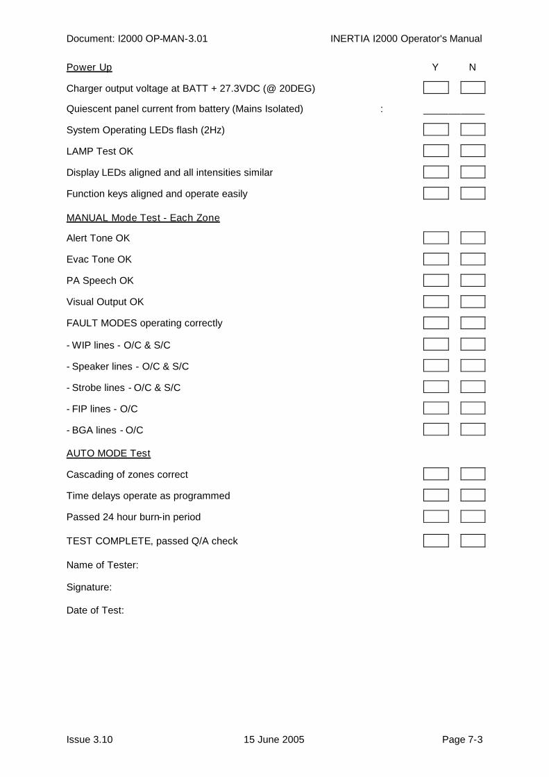
Power Up Y N
Charger output voltage at BATT + 27.3VDC (@ 20DEG)
Quiescent panel current from battery (Mains Isolated) :
System Operating LEDs flash (2Hz)
LAMP Test OK
Display LEDs aligned and all intensities similar
Function keys aligned and operate easily
MANUAL Mode Test - Each Zone
Alert Tone OK
Evac Tone OK
PA Speech OK
Visual Output OK
FAULT MODES operating correctly
- WIP lines - O/C & S/C
- Speaker lines - O/C & S/C
- Strobe lines - O/C & S/C
- FIP lines - O/C
- BGA lines - O/C
AUTO MODE Test
Cascading of zones correct
Time delays operate as programmed
Passed 24 hour burn-in period
TEST COMPLETE, passed Q/A check
Name of Tester:
Signature:
Date of Test:

INERTIA I2000 Operator's Manual Document: I2000 OP-MAN-3.01
Page 7-4 15 June 2005 Issue 3.01
Page 8-1 15 June 2005 Issue 3.01
8 SYSTEM MAINTENANCE
INERTIA I2000 Operator's Manual Document: I2000 OP-MAN-3.01
Page 8-2 15 June 2005 Issue 3.01
8.1 MONTHLY TESTING
The INERTIA I2000 EWIS Panel is designed for high reliability and minimum maintenance.However, in order to comply with the requirements of AS1851.10, the owner/occupier (ornominated representative) must carry out periodic inspections and maintenance checks.
The recommended procedure for monthly testing is :
STEP 1: Inform all building occupants that testing is to take place. Inform the local firecontrol authority, if required, that testing of the EWIS is to take place and thatsimulated fire alarm calls may be generated from the Fire Indicator Panel.
STEP 2: Visually inspect the cabinet and panel to ensure it is clean, operable and thatsystem components are free from damage. Inspect the dust seal and ensurethat it is undamaged.
STEP 3: Place the panel in the MANUAL operating mode and perform a lamp test forboth the Evacuation and Fire Phone Systems. Check that all LEDs operate.
STEP 4: Check the operation of each zone by selecting each of ALERT, EVACUATE andPA SPEECH tones and verifying that the speakers and warning lights areoperational.
STEP 5: Check the operation of the Warden Intercom function for each installed WIP bycalling each WIP and requesting that they call the Master back.
STEP 6: Where the system is connected to a Fire Indicator Panel, place the EWIS panelin AUTO mode and simulate a fire alarm at the associated FIP. Check that thealarm is indicated at the MECP as well as any connected SECP. Check that theALERT tone is automatically distributed to the appropriate zones with the correcttime delay.
When the time delay has expired, the tone should automatically change to theEVACUATE tone interspersed with the digitised voice message.
If the EWIS is fitted with a cascade sequence, check that the automaticevacuation sequence is initiated from the alarm zone and that it spreadsthroughout the building.
Return the keyswitch to MANUAL and turn off all selected tones and remove thesimulated fire alarm.
STEP 7: Return all panel switches and controls to their normal operating position.
STEP 8: Inform the building occupants and the local fire control authority that testing isconcluded.
STEP 9: Record the results of these tests in the logbook and ensure that the owner signsthe logbook.
Document: I2000 OP-MAN-3.01 INERTIA I2000 Operator's Manual
Issue 3.10 15 June 2005 Page 8-3
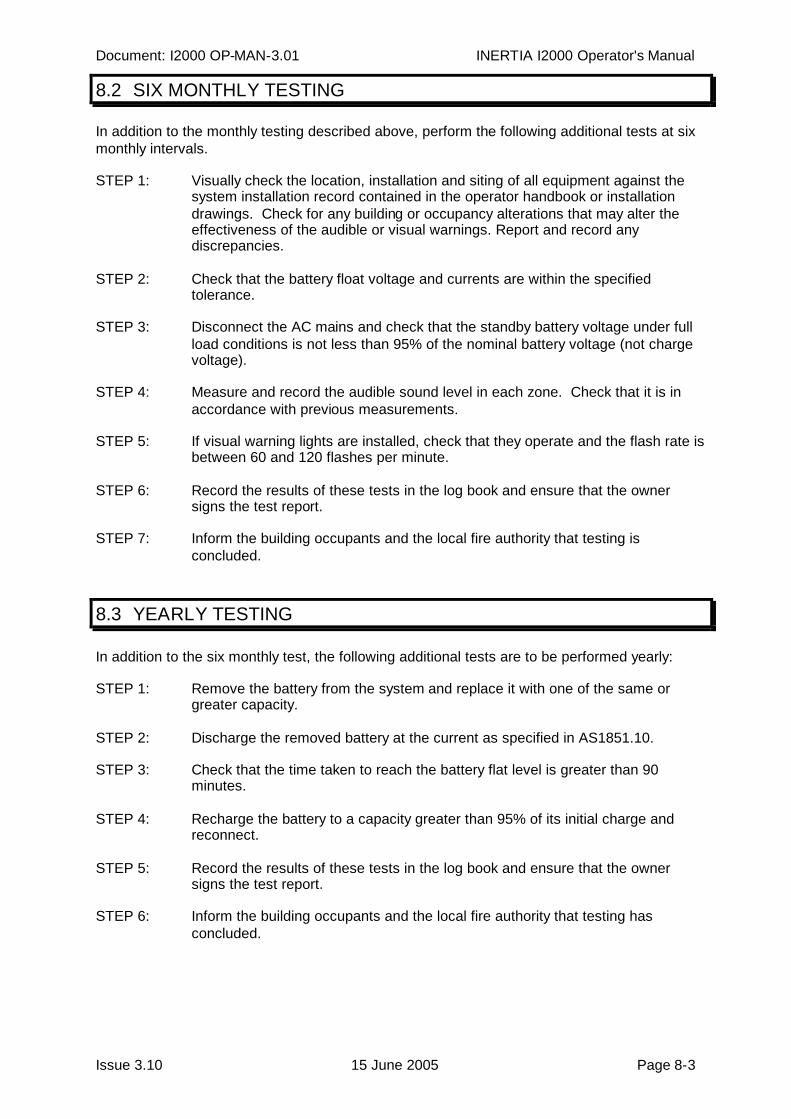
8.2 SIX MONTHLY TESTING
In addition to the monthly testing described above, perform the following additional tests at sixmonthly intervals.
STEP 1: Visually check the location, installation and siting of all equipment against thesystem installation record contained in the operator handbook or installationdrawings. Check for any building or occupancy alterations that may alter theeffectiveness of the audible or visual warnings. Report and record anydiscrepancies.
STEP 2: Check that the battery float voltage and currents are within the specifiedtolerance.
STEP 3: Disconnect the AC mains and check that the standby battery voltage under fullload conditions is not less than 95% of the nominal battery voltage (not chargevoltage).
STEP 4: Measure and record the audible sound level in each zone. Check that it is inaccordance with previous measurements.
STEP 5: If visual warning lights are installed, check that they operate and the flash rate isbetween 60 and 120 flashes per minute.
STEP 6: Record the results of these tests in the log book and ensure that the ownersigns the test report.
STEP 7: Inform the building occupants and the local fire authority that testing isconcluded.
8.3 YEARLY TESTING
In addition to the six monthly test, the following additional tests are to be performed yearly:
STEP 1: Remove the battery from the system and replace it with one of the same orgreater capacity.
STEP 2: Discharge the removed battery at the current as specified in AS1851.10.
STEP 3: Check that the time taken to reach the battery flat level is greater than 90minutes.
STEP 4: Recharge the battery to a capacity greater than 95% of its initial charge andreconnect.
STEP 5: Record the results of these tests in the log book and ensure that the ownersigns the test report.
STEP 6: Inform the building occupants and the local fire authority that testing hasconcluded.

INERTIA I2000 Operator's Manual Document: I2000 OP-MAN-3.01
Page 8-4 15 June 2005 Issue 3.01
Issue 3.01 15 June 2005 Page A-1
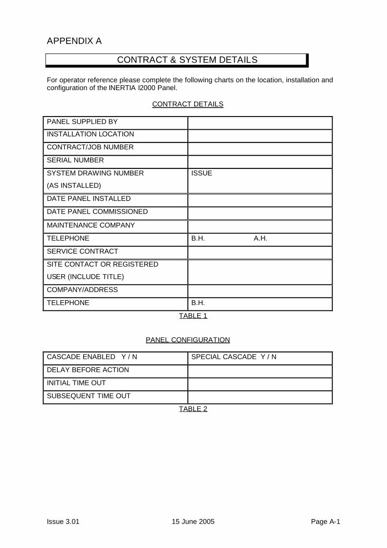
APPENDIX A
CONTRACT & SYSTEM DETAILS
For operator reference please complete the following charts on the location, installation andconfiguration of the INERTIA I2000 Panel.
CONTRACT DETAILS
PANEL SUPPLIED BY
INSTALLATION LOCATION
CONTRACT/JOB NUMBER
SERIAL NUMBER
SYSTEM DRAWING NUMBER
(AS INSTALLED)
ISSUE
DATE PANEL INSTALLED
DATE PANEL COMMISSIONED
MAINTENANCE COMPANY
TELEPHONE B.H. A.H.
SERVICE CONTRACT
SITE CONTACT OR REGISTERED
USER (INCLUDE TITLE)
COMPANY/ADDRESS
TELEPHONE B.H.
TABLE 1
PANEL CONFIGURATION
CASCADE ENABLED Y / N SPECIAL CASCADE Y / N
DELAY BEFORE ACTION
INITIAL TIME OUT
SUBSEQUENT TIME OUT
TABLE 2

INERTIA I2000 Operator's Manual Document: I2000 OP-MAN-3.01
Page A-2 15 June 2005 Issue 3.01
ZONE CONFIGURATION
EVACUATIONZONE
CORRESPONDINGFIRE ZONE
RATINGOF
AMPLIFIER
BGAY/N
# OFSTROBES
BGMENABLED
Y/N
GROUPCOMMAND
# OFWIP
S
A E PA