influence of dental chair backrest inclination on...
TRANSCRIPT

INFLUENCE OF DENTAL CHAIR BACKREST
INCLINATION ON THE THREE DIMENSIONAL
POSITIONING OF THE MANDIBLE
– A CLINICAL TRIAL.
A Dissertation submitted
in partial fulfilment of the requirements
for the degree of
MASTER OF DENTAL SURGERY
BRANCH –I
PROSTHODONTICS AND CROWN & BRIDGE
THE TAMIL NADU DR.M.G.R. MEDICAL UNIVERSITY
CHENNAI- 600032
2015-2018

ADHIPARASAKTHI DENTAL COLLEGE & HOSPITAL
MELMARUVATHUR- 603319
DEPARTMENT OF PROSTHODONTICS
CERTIFICATE
This is to certify that DR.S.ELAKKIYA , Post Graduate student
(2015-2018) in the Department of Prosthodontics, Adhiparasakthi Dental
college and Hospital, Melmaruvathur-603319, has done this dissertation
titled “Influence of dental chair backrest inclination on the three
dimensional positioning of the mandible – A Clinical Trial.” under
our direct guidance and supervision in partial fulfilment of the
regulations laid down by the Tamilnadu Dr. M.G.R medical university,
Chennai-600032 for MDS; (Branch –I) Prosthodontics degree
examination.
Co-Guide Guide
Dr.A.S.RAMESH, MDS Dr. A.S.RAMESH., MDS
Professor and HOD Professor and HOD
Department of Prosthodontics
Principal
Dr. S. THILLAINAYAGAM., MDS
Professor and Head,
Department of Operative Dentistry

ACKNOWLEDGEMENT
I thank ALMIGHTY GOD for all his blessings and for being with
me throughout and leads me to prepare and complete this dissertation.
I am extremely grateful to Dr. A.S. Ramesh MDS., Guide,
Professor and Head, Department of Prosthodontics, Adhiparasakthi
Dental College and Hospital, Melmaruvathur. Words cannot express my
gratitude for his quiet confidence in my ability to perform this study, his
willingness to help to clear the stumbling blocks along the way and his
motivation and tremendous patience till the end of the study.
My sincere thanks to Dr. S. Thillainayagam MDS., Our beloved
Principal, Adhiparasakthi Dental College and Hospital, Melmaruvathur
for providing me with the opportunity to utilize the facilit ies of the
college.
I thank our Correspondent Dr. T. Ramesh, MD., for his vital
encouragement and support.
I am extremely thankful to my teachers Dr. Venkatesh MDS.,
Professor, Dr. Prabhu MDS. Reader, Dr. Kirubakaran MDS., Senior
lecturer, Dr. Raghunanthan MDS., Senior lecturer,
Dr. Karthik, MDS . , senior lecturer, Dr. Ramesh Karthik, MDS . ,
senior lecturer, for their valuable suggestions, constant encouragement
and timely help rendered throughout this study.
I am extremely grateful to Dr. Nathan MDS., for his favour
rendered for my study.
I thank Mr. K. Bhoopathi M.Sc, MBA., Dept of Biostat, ICMR
National Institute of Epidemiology, Chennai, for helping me with the
statistics in the study.
I thank Mr. Maveeran. P, Librarian, Mr. Selvakumar and all the
library staffs, AdhiParasakthi Dental College and Hospital
Melmaruvathur for favours rendered.
I also wish to thank my Post graduate colleagues,
Dr. S. Vinoth Kumar, Dr. A. Maniarasan and I warmly acknowledge
my senior and my Juniors, for their help and support.
A special mention of thanks to all my patients for their consent,
co-operation and participation in this study.
I owe my gratitude to my Father Mr. T. Sundaramoorthi and
my Mother Mrs. J. Balasundari who stood beside me during my
hard time and sacrificed so much to make me what I am today.
I thank my loving husband Dr. S. Saravana Kumar MDS., who
has been a constant source of support and encouragement during the
challenges of graduate and life.
I also thank my lovely sister Dr. Ezhil Pallavi MDS., and my In-
laws Mr. G. Sivakumar and Mrs. S. Uma for their constant help and
encouragement throughout my career. I want to thank my best friend
Dr. Sushruti Manica MDS., for her moral support and encouragement
throughout.
Dr. S. ELAKKIYA
Post Graduate student

DECLARATION
TITLE OF THE
DISSERTATION
Influence of dental chair backrest
inclination on the three dimensional
positioning of the mandible – A Clinical
Trial.
PLACE OF THE STUDY Adhiparasakthi Dental College and
Hospital, Melmaruvathur -603319.
DURATION OF THE
COURSE
3 Years
NAME OF THE GUIDE Dr.A.S.Ramesh, MDS.
NAME OF CO-GUIDE Dr. A.S.Ramesh, MDS.
I hereby declare that no part of the dissertation will be utilized
for gaining financial assistance or any promotion without obt aining
prior permission of the Principal, Adhiparasakthi Dental college and
Hospital, Melmaruvathur -603319. In addition, I declare that no part
of this work will be published either in print or in electronic media
without the guides knowledge who have been actively involved in
dissertation. The author has the right to reserve for publish work solely
with the permission of the principal, Adhiparasakthi Dental college and
Hospital, Melmaruvathur -603319.
Co-guide Guide & Head of Department
Signature of candidate
ABSTRACT
BACKGROUND:
The maxillo-mandibular component of the craniofacial system
consists of a group of organs and tissues that act harmoniously with
interdependent mechanism. In conjunction with the neuromuscular system,
the temporomandibular joint allows the mandible to perform various
movements in the three dimensions. The mandibular position is influenced
by various factors and functions like mouth opening, speech and chewing.
Patient position and head orientation in the dental chair plays a major role
in occlusal rehabilitation. So the head position of the patient plays a major
role while recording centric relation and in prosthetic rehabilitation. Thus
it is important to identify the influence of backrest inclination, on the
registration of the mandibular position during dental treatment procedures.
Aim and Objective:
To study the influence of dental chair backrest inclinations on the 3-
Dimentional positioning of the mandible.
Materials and Methods:
Total of 10 subjects with permanent dentition up to second molar
with healthy periodontium and normal motor and temporomandibular
functions to be selected. The chair was stabilized to check mandibular
positions at 2 inclinations: 90°and 180°.To register the mandibular

position, inter-occlusal records were made in centric relation for each
subject at the said inclinations. Two CBCT were made for each subject
with the inter-occlusal records registered at two different inclinations of
the dental chair backrest respectively. The CBCT images were analyzed to
study the 3-dimentional positioning of the mandible to the
temporomandibular joint.
Result:
There was a significant retrusion of the mandible coupled with an
upwards and forwards rotation of the mandible. The mandible is also
superiorly positioned as seen by the reduction of the intra capsular space.
Conclusion:
It is essential to make registrations of the mandible with the patient
seated erect and the chair at 90*, or else a change in mandibular position
will complicate rehabilitation.
Key words: Mandibular position, centric relation, Inter-Occlusal record,
Dental chair, CBCT, Chair inclination.

CONTENTS
S.NO TITLE PAGE NO
1. INTRODUCTION 1
2. AIM AND OBJECTIVES 5
3. GENERAL REVIEW 6
4. REVIEW OF LITERATURE 9
5. MATERIALS AND METHODS 14
6. RESULTS 24
7. DISCUSSION 30
8. SUMMARY 37
9. CONCLUSION 38
10. REFERENCES 39
11 ANNEXURE 64
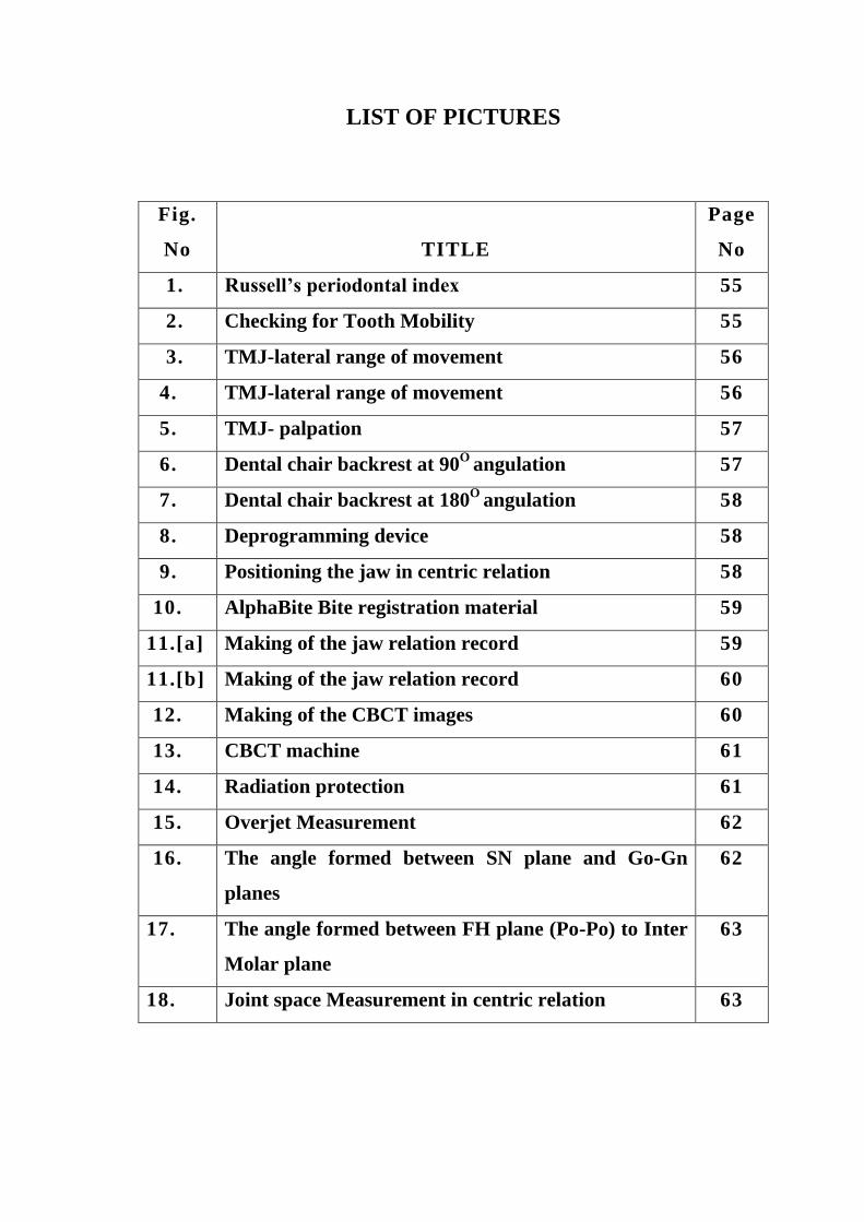
LIST OF PICTURES
Fig.
No
TITLE
Page
No
1. Russell’s periodontal index 55
2. Checking for Tooth Mobility 55
3. TMJ-lateral range of movement 56
4. TMJ-lateral range of movement 56
5. TMJ- palpation 57
6. Dental chair backrest at 90O
angulation 57
7. Dental chair backrest at 180O
angulation 58
8. Deprogramming device 58
9. Positioning the jaw in centric relation 58
10. AlphaBite Bite registration material 59
11.[a] Making of the jaw relation record 59
11.[b] Making of the jaw relation record 60
12. Making of the CBCT images 60
13. CBCT machine 61
14. Radiation protection 61
15. Overjet Measurement 62
16. The angle formed between SN plane and Go-Gn
planes
62
17. The angle formed between FH plane (Po-Po) to Inter
Molar plane
63
18. Joint space Measurement in centric relation 63

LIST OF TABLES
Table
No
TITLE
Page
No
1. CBCT Analysis 46
2. Mandibular plane - SN-Go-Gn plane angle 47
3. FH plane (Po-Po) to Inter Molar plane angles 47
4a. Space between glenoid fossa and condylar head -
Anterior (mm)
47
4b. Space between glenoid fossa and condylar head -
Middle (mm)
47
4c. Space between glenoid fossa and condylar head -
Posterior (mm)
47
5. Overjet 47
6. Paired Differences 48

LIST OF CHARTS
Chart
No
TITLE
Page
No
1. Mandibular plane - SN-Go-Gn plane angle 49
2. FH plane (Po-Po) to Inter Molar plane angles 49
3a. Space between glenoid fossa and condylar head -
Anterior (mm)
50
3b. Space between glenoid fossa and condylar head -
Middle (mm)
50
3c. Space between glenoid fossa and condylar head -
Posterior (mm)
51
4. Overjet 51
5. Mandibular plane - SN-Go-Gn plane angle 52
6. FH plane (Po-Po) to Inter Molar plane angles 52
7. Space between glenoid fossa and condylar head -
Anterior (mm)
53
8. Space between glenoid fossa and condylar head -
Middle (mm)
53
9. Space between glenoid fossa and condylar head -
Posterior (mm)
54
10. Overjet 54

Introduction
1
INTRODUCTION
The maxillomandibular component of the cranio-maxillary system
consists of a group of organs and tissues that act harmoniously with
interdependent mechanism. Temporomandibular joint is the only
movable joint in the head. In conjunction with the neuromuscular
system, the temporomandibular joint allows mandible to perform various
movements 3-dimensionally[ 1 , 2 ]
. Among the various mandibular
positions, the centric relation position, is where there is a state of near
physiologic rest as dictated by mandible and the temporomandibular
joint and it is determined the ligaments and muscles of
mastication[ 3 ,4 , 5 ]
. The mandibular position is influenced by various
factors and functions like mouth opening, speech and chewing. The
position of the body and head, quality of sleep, psychological factors
that alter muscle tone, proprioception, occlusal changes, muscle spasms,
and temporomandibular joint dysfunction have all been reported to
influence mandibular postural position. Functional and static occlusion
can be analysed with casts mounted in articulator. Semi-adjustable
articulators, although somewhat limited, are capable of reproducing
maxillomandibular relations and are important for diagnosing and
planning prosthetic treatment [ 3 ]
.
The great variety of treatments used in modern dentistry makes it
necessary for dental chairs to be adjustable so that the dentist can
position the patient in the most convenient and comfortable position for
each particular treatment. Particular adjustment features should include

Introduction
2
provision for adjusting the elevation of the chair above the floor, the
orientation of the chair, and the inclinations of the seat and backrest
portions of the chair. The elevation adjustment mechanism should be as
compact as possible without sacrificing strength and safety, so that the
dentist 's knees can extend under the seat when he is working close to the
patient in a seated position. The adjustment mechanism for the seat and
backrest inclinations should be interrelated, so that the seat and backrest
are always automatically held in the best relative orientation for patient
comfort. All adjustment mechanisms should be easy to use and should be
as mechanically simple as possible so as to reduce manufacturing and
maintenance costs. Finally, the dental chair should be comfortable and
should be designed so that it is as easy as possible for the patient to get
on and off the chair[ 6 , 7 ,8 ,9 ]
.
Patient position and head orientation in the dental chair plays a
major role in occlusal rehabi litation[ 1 0 ,1 1 ,12 ]
. In literatures, i t has been
mentioned that the Frankfort Horizontal plane of the patient should be
parallel to the floor while making the occlusal reco rds, which will result
in a most reproducible occlusal rehabilitation, as they are made under
patient`s physiological rest position of the temporomandibular joints.
When there is an alteration between the FH plane and floor parallelism
due to change in the back rest angulation of the dental chair, wh ich
might influence the temporomandibular joint and thereby the occlusal
rehabilitation[ 13 ,14 ]
.So the head position of the patient plays a major role
while recording centric relation and in prosthetic rehabilitation.

Introduction
3
IMAGING:
Imaging is an important diagnostic adjunct to the clinical
assessment of the dental patient. The introduction of panoramic
radiography in the 1960s and its widespread adoption throughout the
1970s and 1980s made major progress in dental radiology, providing
clinicians with a single comprehensive image of jaws and maxillofacial
structures. However, intraoral and extra oral procedures, used
individually or in combination, suffer from the same inherent l imitations
of all planar two-dimensional (2D) projections: magnification,
distortion, superimposition, and misrepresentation of structures.
Numerous efforts have been made toward three -dimensional (3D)
radiographic imaging (eg, stereoscopy, tuned aperture CT) and alth ough
CT has been available, its application in dentistry has been limited
because of cost, access, and dose considerations. The introduction of
cone-beam computed tomography (CBCT) specifically dedicated to
imaging the maxillofacial region heralds a true p aradigm shift from a 2D
to a 3D approach to data acquisition and image reconstruction. Interest
in CBCT from all fields of dentistry is evident because it has created a
revolution in maxillofacial imaging, facilitating the transition of dental
diagnosis from 2D to 3D images. CBCT is a recent technology. Imaging
is accomplished by using a rotating gantry to which an x-ray source and
detector are fixed. A divergent pyramidal - or cone-shaped source of
ionizing radiation is directed through the middle of the ar ea of interest
onto an area x-ray detect or on the opposite side. The x -ray source and
detector, rotate around a rotation fulcrum fixed within the centre of the

Introduction
4
region of interest. During the rotation, multiple (from 150 to more than
600) sequential planar projection images of the field of view (FOV) are
acquired in a complete, or sometimes partial, arc. This procedure varies
from a traditional medical CT, which uses a fan -shaped x-ray beam in a
helical progression to acquire individual image slices of the FOV and
then stacks the slices to obtain a 3D representation. Each slice requires
a separate scan and separate 2D reconstruction. Because CBCT exposure
incorporates the entire FOV, only one rotational sequence of the gantry
is necessary to acquire enough data for image reconstruction[ 1 5 ,16 ,1 7 ]
.

Aims and Objectives
5
AIMS AND OBJECTIVES
For comfort sake, in 4 handed dentistry, the patient is usually put
in supine position to work with. But when jaw relation records are made
in this position they might be erraneous. To check the dental chair
backrest angulation and its influence on the man dibular position various
2-Dimensional studies have been conducted and the studies concluded
that the mandibular position is influenced by the dental chair back rest
angulations to certain extent. For further clarification, a 3-Dimentional
study of the mandibular position under different dental chair backrest
angulations was done. On the basis of clinical observations, i t has been
hypothesized that the change in the inclination of the chair could lead to
a different head inclination and consequently a diff erent mandible
position. The purpose of this study was to examine the extent of
influence of different chair inclinations (90 degrees and 180 degrees) 3 -
Dimentionally on the registration of mandibular positions.
General Review
6
GENERAL REVIEW
The rationale of recording Centric Relation records is to establish
guidelines as starting point to develop occlusion with artificial teeth in
harmony with the various structures of masticatory apparatus including
TMJ. It aids to maintain physiologic as we ll as anatomic health of
tissues. When maximum intercuspation is coinciding with centric
position, it provides stability to the prosthesis thereby preserving the
health of remaining tissues (edentulous foundation, remaining natural
teeth, musculature and TMJ)[ 18 ,19 ,2 0 ]
. An occlusal analysis in relation to
the TMJ radiographs will reveal factors that should be added to the
purely clinical definition of centric relation. It has been previously
established that bilateral asymmetric TMJ spaces and condylar retr usion
or protrusion are most often associated with disc derangement and/or
palpable muscle spasm. Conversely, bilateral TMJ space symmetry and
condylar concentricity (condyle centred in the superior portion of the
glenoid fossa) are associated with joint a nd muscle health. All TMJ
radiographs are obtained with the teeth in the acquired centric
occlusion[ 2 1 ,22 ,23 ,2 4 ]
.Centric relation is considered functional , when the
magnitude and direction of the centric relation deflective slide to the
acquired centric occlusion correlate with the condylar displacement
observed on the TMJ radiographs. For example, if the patient has a 2
mm. deflective slide straight forward, the centric relation is considered
functional when the TMJ radiographs reveal equal condylar protrusion
proportional to the mandibular deflection. In the judgment of the
General Review
7
dentist , the occlusal correction of the deflective contacts will result in
bilateral condylar concentricity. Conversely, centric relation is
dysfunctional when the magnitude and direction of the centric relation
deflective slide to the acquired centric occlusion do not correlate with
condylar position in the TMJ radiographs. When no deflective slide is
present, both condyles should be concentrically located in each fossa
with bilateral symmetrical joint spaces in order for centric relation to be
considered functional. Dysfunctional centric relation is often associated
with disc derangement and/or palpable muscle spasm. When t he centric
relation is functional, the most retruded jaw position should be used. If
the centric relation is dysfunctional, a therapeutic or treatment centric
occlusion must be established by the dentist , utilizing the TMJ
radiographs as a guide[ 2 5 ,26 ,27 ,2 8 ]
.Centric occlusion is the occlusion of
opposing teeth when the mandible is in centric relation. Centric
occlusion is the first tooth contact and may or may not coincide with
maximum intercuspation. It is also referred to as a person's habitual
bite, bite of convenience, or intercuspation position . Centric relation is
currently understood as the maxillomandibular relation in which the
condyles articulate with the thinner and avascular portion of their
respective discs; this set occupies an antero -superior position, against
the posterior inclination of the articular eminence. It is considered a
position that does not depend on any dental contact and is clinically
discernible when the mandible is positioned supero-anteriorly and is
restricted to a rotation movement around a transverse horizontal
axis[ 2 9 ,30 ,31 ]
.To register these maxillomandibular relations, some

General Review
8
techniques use intraoral devices that deprogram muscles to facilitate
moving the mandible into various positions according to the planned
treatment[ 3 2 ,33 ]
.

Review of Literature
9
REVIEW OF LITERATURE
1. Atwood DA. (1966) did a critique of research of the rest position
of the mandible and stated that the postural position of the
mandible is not a single absolute position, but a range of
positions; that the width of the range will vary from individual to
individual and within the same individual at different times. J
Prosthet Dent 1966; 16:848-54.
2. Weinberg LA. (1983) did a review on the role of stress, occlusion,
and condyle position in TMJ dysfunction pain. J Prosthet Dent
1983;49:532-45.
3. Ayub E, Glasheen-Wray M, Kraus S. (1984) did a study on head
posture and its effect on the rest position of the mandi ble and
stated that correction of a forward head posture may effect the
resting vertical dimension of the mandible. Manual physical
therapy techniques were successful in assisting a patient to obtain
a desired head to thorax posture as described in the st andard
posture. J Orthop Sports Phys Ther 1984; 5:179 -83.
4. Utt TW et al. , (1995) did a three dimensional comparison of
condylar position changes between centric relation and centric
occlusion using the mandibular position indicator and stated that
condylar position is influenced by centric occlusion than centric
relation which is statistically significant. Am J
OrthodDentofacialOrthop 1995; 107:298 -308.
5. Fantini SM, Paiva JB, RinoNeto J, Dominguez GC, Abrão J,
Vigoritto JW. (2005) did a study on increase o f condylar

Review of Literature
10
displacement between centric relation and maximal habitual
intercuspation after occlusal splint therapy and stated that use of
occlusal splints results in greater mean condylar displacement
values, especially vertically, between CR and MHI posit ions,
which contributed to a more accurate orthodontic diagnosis. Braz
Oral Res 2005; 19:176-82.
6. Cordray FE (2006) did a prospective study on three -dimensional
analysis of models articulated in the seated condylar position from
a deprogrammed asymptomatic population and stated that the
neuromuscular deprogramming, registering the SCP/CR and
mounting orthodontic study casts in the SCP/CR on a semi
adjustable articulator enhance the diagnosis by yielding
information that is not available from intraoral visual estimation.
Am J OrthodDentofacialOrthop 2006; 129:619 -30.
7. Weffort SYK et al. , (2010) did a study on condylar displacement
between centric relation and maximum intercuspation in
symptomatic and asymptomatic individuals and stated that
statistically signif icant differences between CR and MIC were
quantifiable at the condylar level in asymptomatic and
symptomatic individuals. Angle Orthod 2010; 80:835 -42.
8. Okeson JP, de Leeuw R. (2011) did a differential diagnosis of
temporomandibular disorders and other orofacial pain disorders
and concluded that there are many types of pain conditions that
produce orofacial pain. The most common are dental and
periodontal pains, some of the other common pain disorders are
Review of Literature
11
musculoskeletal, which in the orofacial structures are called TMD.
These disorders need to be identified by the dentist and can be
managed by relatively simple strategies. Dental Clin North Am
2011; 55:105-20.
9. Etz E, Hellmann D, Giannakopoulos NN, Schmitter M,
RammelsbergP,Schindler HJ. (2012) did a study on the variability
of centric jaw relations in the process chain of prosthetic
restorations and their neuromuscular effects and stated that the
presence of prosthesis in a patients mouth had an effect on the
accuracy of the jaw relation records made . J CraniomandFunc
2012:141-56.
10. Fleigel JD et al. , (2013) did a study on reliable and repeatable
centric relation adjustment of maxillary occlusal device and stated
that the occlusal device is now suitable for extended use due to
stable centric occlusal tooth contacts and comfortable disclusive
angles. Journal of Prosthodontics 2013; 22:233 -36.
11. Gomes Lde C, Horta KO, Goncalves JR, Santos -Pinto AD. (2014)
did a systematic review on craniocervical posture and craniofacial
morphology and concluded that there is signifcant associations
were found between variables concerning head posture and
craniofacial morphology. Eur J Orthod 2014; 36:55 -66.
12. Wiens JP, Priebe JW. (2014) gave a brief description about
Occlusal stability in various prosthetic restorations . Dental Clin
North Am 2014;58:19-43.

Review of Literature
12
13. Mariana Freire Coelho et al . , (2015) did a study on influence of
dental chair backrest inclination on the registration of the
mandibular position and stated that mandibular position is
influenced by increasing inclination, and this influence was
statistically significant at a 180 degree incline. Journal Prosthetic
Dentistry, November 2015; 114:693-695.
14. Okeson JP. (2013) gave a brief description about the management
of temporomandibular disorders and occlusion. 7t h
edition. St
Louis: Mosby; 2013.
15. Dawson PE.(1995) gave a new definition for relating occlusion to
varying conditions of the temporomandibular joint. J Prosthet
Dent 1995;74:619-27.
16. Sanjay Bansal. (2008) did a review on Critical evaluation of
various methods of recording centric jaw relation and concluded
that there are many opinions and much confusion concerning
Centric Relation records. A certain technique might be required
for an unusual situation or a problempatient. In the final analysis,
the skill of the dentist and the cooperation of the patient are
probably the most important factors in securing an accurate
CentricRelation record.The Journal of Indian Prosthodontic
Society. December 2008; Vol 8, Issue 4.
17. In-Young Park. (2015) did a study on Three-dimensional cone-
beam computed tomography based comparison of condylar
position and morphology according to the vertical skeletal pattern
and stated thatCondylar position and morphology vary according
Review of Literature
13
to vertical facial morphology. This relationship should be
considered for predicting and establishing a proper treatment plan
for temporomandibular diseases during orthodontic
treatment.Korean J Orthod. 2015 Mar;45(2):66 -73.
18. Scarfe, W. C., & Farman, A. G. (2008) gave a brief description
about what is cone-beam CT and how does it work? Dental Clinics
of North America , 52(4), 707-730.

Materials and Methods
14
MATERIALS AND METHODS
Selection of subjects:
Total of 10 subjects with permanent dentition up to second molar
with or without third molar with healthy periodontium and normal motor
and temporomandibular functions were selected.
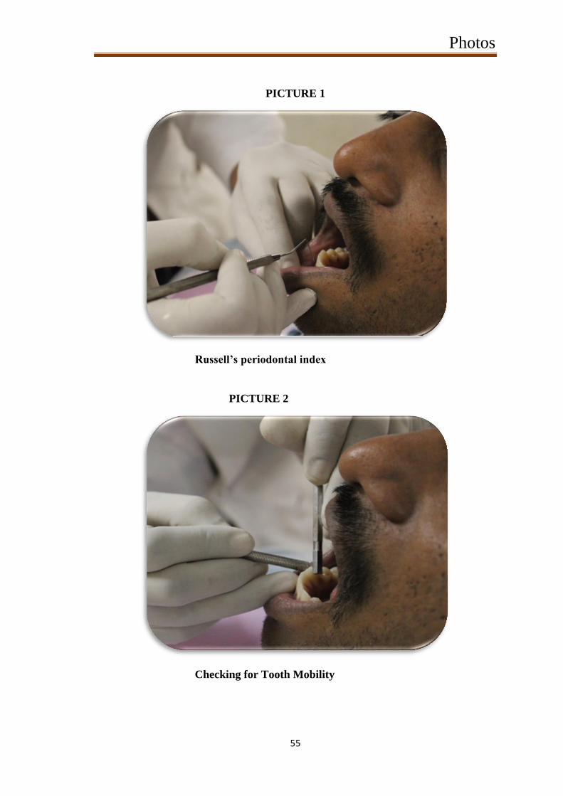
Periodontal health status is evaluated using Russell’s periodontal
index.
Tooth mobility, motor and temporomandibular functions are
evaluated by clinical examination.
Clinical examination of the subjects:
Russell’s periodontal index:[3 4 ]
[picture 1]
Russell developed an index for measuring periodontal disease
which can be based solely upon the clinical examination or, it can make
use of radiograph.
The subjects teeth were examined clinically using CPITN probe
and Russell’s periodontal index scores were recorded. The subjects with
a score of 0 and 1 were considered to have healthy periodontium and
were included in the study.
Checking for Tooth Mobility:[ 3 5 ,36 ]
[picture 2]
Mobility is graded clinically by applying pressure with the ends of
2 metal instruments (e.g. dental mirrors) and trying to rock a tooth
gently in a bucco-lingual direction (towards the tongue and outwards
again). Using the fingers is not reliable as they are too compressible and

Materials and Methods
15
will not detect small increases in movement. Normal, physiologic tooth
mobility of about 0.25 mm is present in health.
Grace &Smales Mobility Index is the method followed for
checking tooth mobility in which index are scored from Grade 0 to 3.
The subjects were examined clinically for teeth mobility and
scored using Grace & Smales Mobility Index. The subjects with Grade 0
mobility where only included in the study.
Checking for TMJ function:
INSPECTION [picture 3 & 4]
Facial asymmetry, swelling, masseter or temporalis muscle
hypertrophy muscle Assessment of range of mandibular movements:
maximum mouth opening, lateral movement , deviation while opening ,
protrusive movement The maximum opening distance between the
incisal edges of upper and lower incisor is measured using scale. Normal
opening – 40 to 55 mm. Normal opening can also be est imated by
patient’s own finger. Normal: three finger end on end ,Two finger
opening reveals reduction in opening but not nec essarily reduction in
function, One finger opening indicates reduced function[ 3 7 ,38 ]
.
LATERAL RANGE OF MOVEMENT
Normal lateral range of movement is >7mm Measurements are
made with teeth slightly separated, measuring the displacement of lower
midline from maxillary midline .[ 3 9 ]
PALPATION: [picture 5]
Materials and Methods
16
The lateral aspect of TMJ Palpate directly over the joint while the
patient opens and the mandible, and the extent of mandibular condylar
movement can be assessed. Normally, condylar movement is easily felt.
Have the patient close slowly, and you will feel the condyle move
posteriorly against your finger. Opening involves two motions. First , the
mandibular condyle rotates anteriorly on the disk. Second, the condyle
and the disk both glide anteriorly and inferiorly over the articular
tubercle of the temporal bone .[ 4 0 ]
AUSCULTATION:
JOINT SOUNDS:
There are 2 types of joint sound to look out for: Clicks - single
explosive noise of short duration. Crepitus - continuous 'grating' noise.
CLICKS: A joint click probably represents the sudden distraction of 2
wet surfaces, symptomatic of some kind of disc displacement. The
timing of a click is also significant: a click heard later in the opening
cycle may represent a greater degree of disc di splacement. Clicks may
frequently be felt as well as heard, though they are not normally painful.
CREPITUS: Crepitus is the continuous noise during movement of the
joint, caused by the articulatory surfaces of the joint being worn. This
occurs most commonly in patients with degenerative joint disease. The
joint sounds should be listened to with a stethoscope .[ 41 ]
Inclusion Criteria:
Materials and Methods
17
I. Both male and female subjects aged between 18 to 25 years
with complete permanent dentition up to second molars.
II. Subject with normal motor and temporomandibular functions.
III. Subject with healthy periodontium.
Exclusion Criteria:
I. Subjects below 18 and above 30 years of age
II. Subject with edentulous space.
III. Subject with compromised motor functions
IV. Subject with tooth mobility, and
V. Subject with temporomandibular disorders.
Methodology:
Positioning of the chair:
1. Dental chair with a fixed headrest accompanied with the
inclination of the backrest. To standardize the angles to be used in
the study, a protractor was adapted and positioned on the axis
connecting the chair’s backrest to its seat.
2. The chair was stabilized to check mandibular positions at 2
inclinations: 90° and 180°.
To register the occlusal contacts, inter -occlusal records were made in
centric relation for each subject at various inclinations as mentioned
above. [picture 6&7]
Making of Deprogramming device:
Method followed for making inter -occlusal records:

Materials and Methods
18
Maxillary impression were made with alginate and cast is poured
using dental stone. The deprogrammer was made using clear self -cure
acrylic material in the upper central incisors of the cast and it is
finished and polished. The deprogramming device should be trimmed in
such a way that i t separates the maxillary and mandibular teeth from
occlusion by about 4 to 5mm. The lower slopes of the deprogrammer
should be trimmed to 45 angulation to that of the mandibular incisors.
So that, it guides the mandible in a backwards and posteriorly direction.
[picture 8] The subjects were instructed to wear the deprogrammer for
10 minutes. Which will prevent the maxillary and mandibular teeth from
contact and thereby the engram is lost. Now the temporomandibular
joint was guided to centric relation for obtaining occlusal record by the
operator.
Positioning the jaw in centric relation: [picture 9]
The operator guided the mandible into a posterior position,
applying slight pressure . Using three fingers of one hand, moderate,
inclined pressure was applied to the chin. During this procedure, the test
subjects were asked to place the tongue in the dorsal direction against
the palate as far as possible.
The AlphaBite Bite registration material was the material used for
making inter-occlusal records.
AlphaBite Bite registration material:[ 4 2 ]
[picture 10]
Danville Materials offers AlphaBite™, a bite registration material
made with the highest quality fil lers and silicones. AlphaBite is non-

Materials and Methods
19
sticky, highly stable, and accurate. AlphaBite’s working time is 30
seconds, with a total set time of 90 seconds. The material comes in 50ml
cartridges in two-packs and four-packs.
After deprogramming, the subjects were asked to sit in the dental
chair in upright position and relax. Now the dental chair backrest was
adjusted to 90 degree angulation and the subjects Frankfort horizontal
plane is made parallel with the floor and Alph aBite™ bite registration
material was injected over the entire occlusal and incisal surface of the
mandible and the mandible was guided to centric relation position by the
operator and the subject was instructed to bite on the bite registration
material in the retruded mandibular position until it sets completely.
Now the dental chair backrest was adjusted to 180 and the bite
registration was done in centric same as in 90 angulation position.
Making of the jaw relation record: [picture 11a & 11b]
Procedure of making the Centric jaw relation:
The subject was asked to sit straight and relaxed. In this position ,
the occlusal records were made using AlphaBite Bite registration
material. The material was injected over the mandibular occlusal and
incisal surface and the mandible was guided to centric relation and the
subject was asked to bite with the bite registration material in place.
The thickness of the bite registration material was r estricted to 4 ± 2
mm for all the samples.
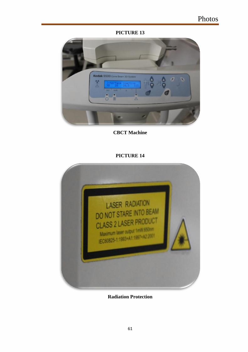
Making of the CBCT images: [picture 12]
Two CBCT was made for each subject.
Materials and Methods
20
1. First CBCT was made with the inter-occlusal record made at 90.
The subject was instructed to bite on the occlusal record in
position and a CBCT was made.
2. Second CBCT was made with the inter -occlusal record made at
180. The subject was instructed to bite on the occlusal record i n
position and a CBCT was made.
Cone beam computed tomography (CBCT) has been widely
accepted for clinical application in dentistry. But, the radiation dose of
CBCT to patient has also caused broad concern. According to the
li terature, the effective radiation doses of CBCTs in market fall into a
wide range that is from 19 µSv to 1073 µSv [19]. [picture 13 & 14]
Considering the radiation exposure to the patient, the following
steps can be implicated
To reduce the patient dose to the greatest possible extent, the
chosen CBCT scanning protocol should be in accordance with the
diagnostic task at hand;
A thyroid collar should be used for CBCT scanning; wearing
leaded glasses is recommended when it does not detract from
imaging quality.
Studying the CBCT images:
The CBCT images was analyzed to study the 3 -dimentional
positioning of the mandible to the temporomandibular joint.
The following points were marked in the CBCT:
1. Sella

Materials and Methods
21
2. Nasion
3. Gonion
4. Gnathion
5. Porion
6. MB cusp of mandibular 1s t
molar.
Brief description about each point[4 3 ]
:
Sella – it is the point in the midpoint of Pituitary Fossa.
Nasion- it is the anterior most point on frontonasal suture.
Gonion-Most posterior inferior point on angle of mandible.Can also be
constructed by bisecting the angle formed by intersection of mandibular
plane and posterior border of ramus of mandible.
Gnathion-Point located perpendicular on mandibular symphysis midway
between pogonion and menton.
Porion-Most superior point of outline of external auditory meatus .
Planes to be studied:
1. Sella-Nasion (SN) Plane.
2. Gonion-Gnathion (Go-Gn) Plane.
3. FH plane. (Po-Po)
4. Inter molar plane.
Brief description about each angle[4 4 ,45 ]
:
Sella-Nasion (SN) Plane- This plane is represents the anterior cranial
base and is formed by connecting Sella to Nasion.
Materials and Methods
22
Gonion-Gnathion (Go-Gn) Plane- This plane represents the mandibular
base and is formed by connecting gonion and gnathion.
FH plane (Po-Po)-This plane represents the habitual postural position
of the head. This is formed by connecting the porion on either side of
the skull.
Inter molar plane- this is formed by connecting the intra -arch mesio-
buccal cusp tip of the mandibular 1s t
molars.
Angles to be read:
The angle formed between SN plane and Go-Gn planes.
The angle formed between FH plane (Po-Po) to Inter Molar plane.
The following measurements are made in the two different CBCT
for each subject and compared
1. The mandibular plane angle as measured by SN-Go-Gn angle.
2. Roll as measured by FH plane (Po-Po) to Inter Molar plane.
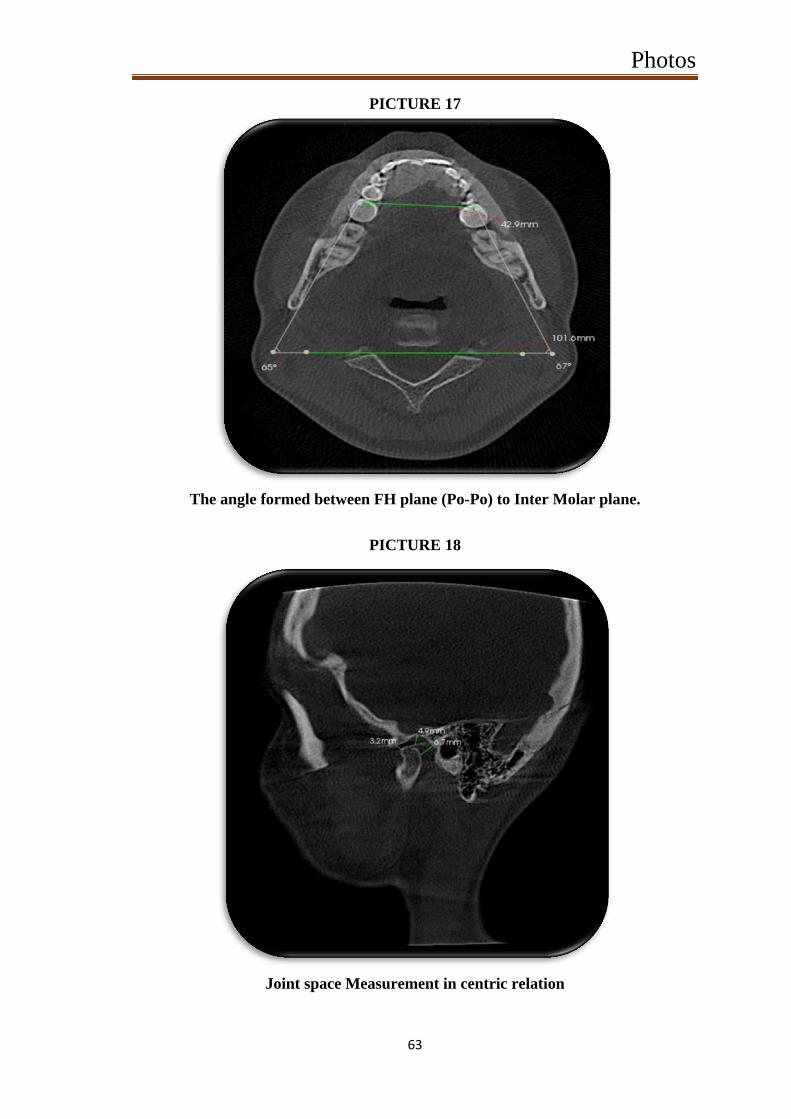
Joint space Measurement in centric relation:
Measurements were made in the anterior, superior and posterior
joint space between the condylar head and glenoid fossa. Anterior,
Superior and Posterior joint spacewere measured in sagittal plane.The
measured values were tabulated for each subject to know the difference
in mandibular position at 90 and 180 inclinations of the dental chair
backrest.
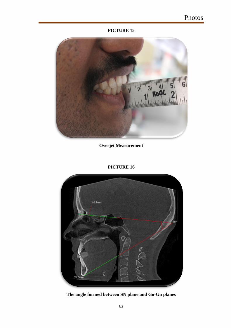
Overjet Measurement: [picture 15]

Materials and Methods
23
The amount of overjet between the maxillary central incisor and
mandibular central incisor in centric relation was measured using a scale
at 900 and 180
0dental chair backrest angulation .

Result
24
RESULT
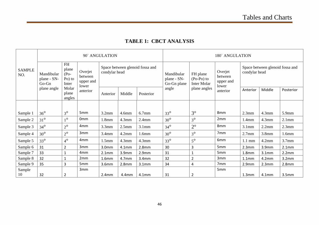
CBCT analysis was done using “CareStream 3D Imaging software”
for the following planes and the data obtained were charted . The values
obtained from the CBCT analysis were shown in table 1.
Rotation of the Mandible: [picture 16]
The mandibular plane angle was measured between two planes, SN
and Go-Gn planes. These two planes intersect to form the mandibular
plane angle. This analysis was done for all the 20 CBCT and the values
were entered as Table 2. The mean and SD for subjects at 90 angulation
was found to be 32.700 and 1.8886 respectively and the mean and SD for
subjects at 180 angulation was found to be 31.800 and 1.6193
respectively.
Roll of the Mandible: [picture 17]
The relationship between the Occlusal plane and the base of the
skull is measured using the angle formed between the two plane FH
Plane (Po-Po) and the inter-molar plane ( mesio-buccal cusp tip of
mandible molar on 1 quadrant to the mesio -buccal cusp tip of
mandibular molar on the other quadrant). After marking these two
planes in the CBCT the angle between them is measured . The values
obtained were entered as shown in Table 3. The mean and SD for all 10
subjects at 90 angulation was found to be 2.100 and 0.9944 respectively
and the mean and SD for all the 10 subjects at 180 angulation was found
to be 2.800 and 1.1353 respectively.
Result
25
Change in Intra Capsular Space: [picture 18]
The space between the condylar head and glenoid fossa was
measured using CareStream3D Imaging software and the anterior,
superior and posterior joint space were measured and charted separately.
The Table 4 [a,b,c], shows the anterior, middle and posterior joint space
measurements between the glenoid fossa and the condylar head.
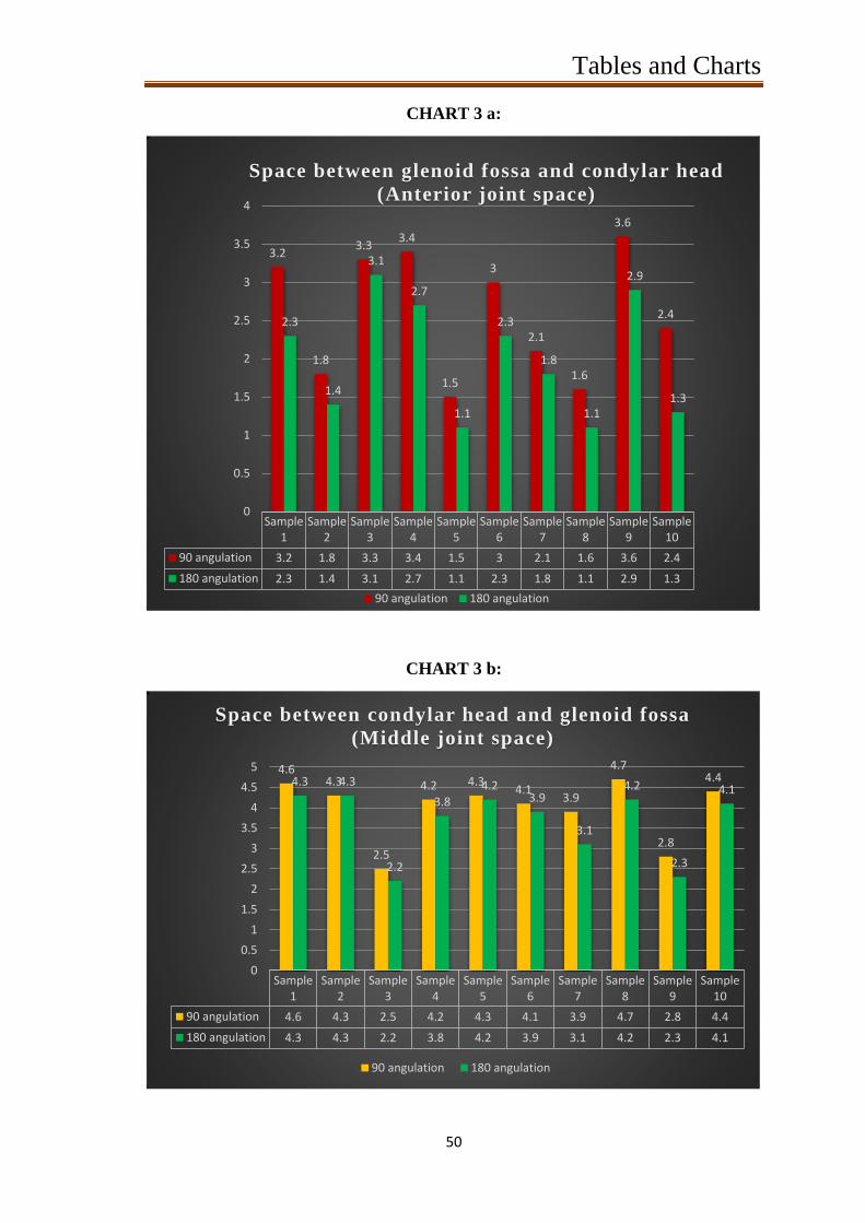
Anterior Space:
The anterior joint space measurement is charted in Table 4a. The
mean and SD for subjects at 90 angulation was found to be 2.590 and
0.8020 respectively and the mean and SD for subjects at 180 angulation
was found to be 2.000 and 0.7601 respectively.
Mid-Capsular Space:
The superior or middle joint space measurement is entered in
Table 4b. The mean and SD for subjects at 90 angulation was found to
be 3.980 and 0.7406 respectively and the mean and SD for subjects at
180 angulation was found to be 3.640 and 0.8140 respectively.
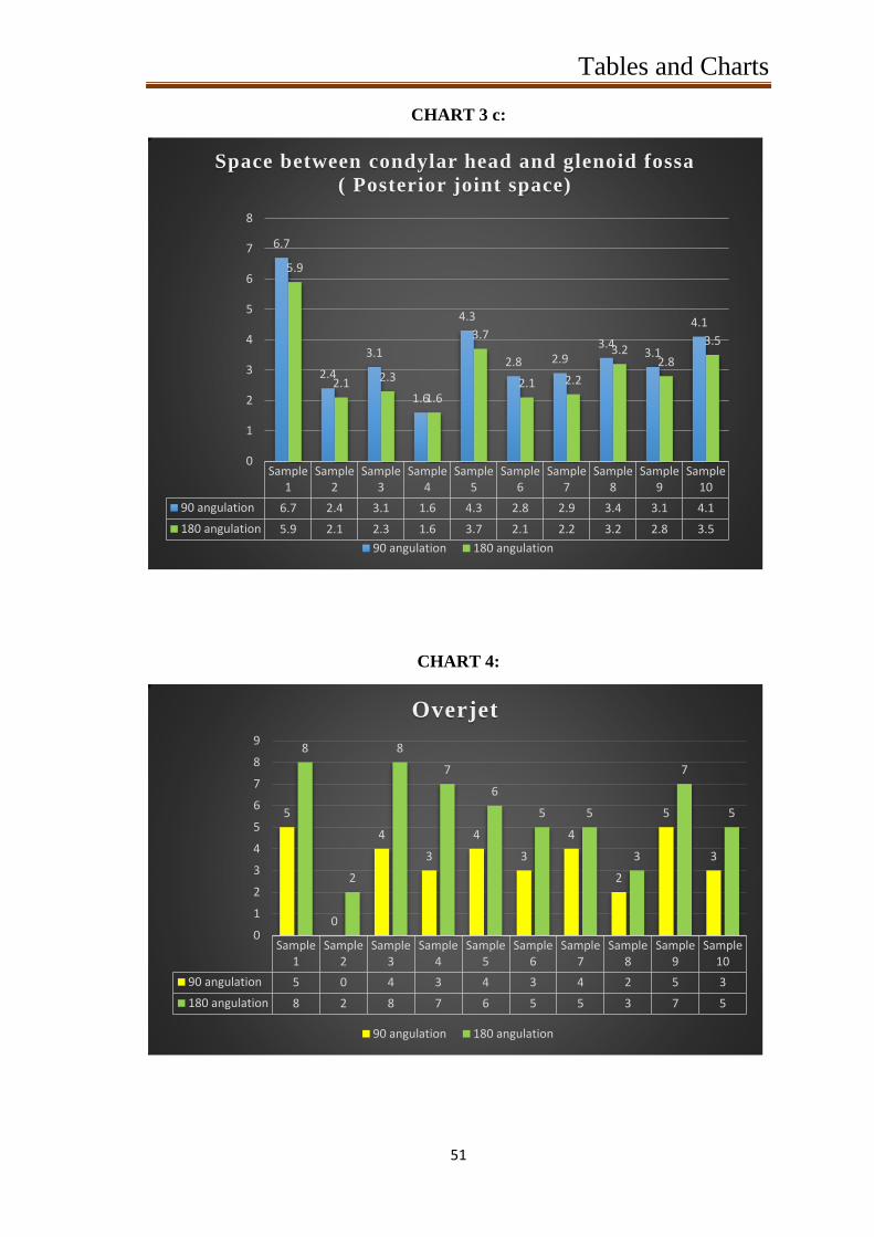
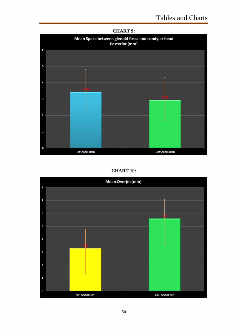
Posterior Joint Space:
The posterior joint space measurement is entered in Table 4c. The
mean and SD for subjects at 90 angulation was fo und to be 3.440 and
1.3826 respectively and the mean and SD for subjects at 180 angulation
was found to be 2.940 and 1.2429 respectively.

Result
26
Overjet:
Amount of overjet at 90 and 180 angulation was recorded in Table
5. The mean and SD for subjects at 90 angulation was found to be 3.3
and 1.4944 respectively and the mean and SD for subjects at 180
angulation was found to be 5.6 and 2.0111 respectively.
Result
27
Statistical Analysis:
Statistical analysis was done using SPSS 17 software. The values
obtained where checked for normality and it followed a normal curve
distribution. So, paired samples T-Test was used to compare the values
between 90 and 180 .
According to Table 2, the mean and SD for all 10 subjects at 90
angulation was found to be 32.700 and 1.8886 respectively and the mean
and SD for all the 10 subjects at 180 angulation was found to be 31.800
and 1.6193 respectively. These values were compared using paired t -
test and the paired difference between 90 and 180 angulation was
analysed. The calculated Mean and SD is 0.9000 and 0.9944 respectively
with 95% confidence interval (table 6) . So it can be said that the mean
will fall in-between 0.1886 to 1.6114 for all the pa irs. The P-Value was
found to be 0.019 which is statistically significant.
According to Table 3, the mean and SD for all 10 subjects at 90
angulation was found to be 2.100 and 0.9944 respectively and the mean
and SD for all the 10 subjects at 180 angulation was found to be 2.800
and 1.1353 respectively. These values were compared using paired t -
test and the paired difference between 90 and 180 angulation was
analysed. The calculated Mean and SD is -0.7000 and 0.6749
respectively with 95% confidence interval (table 6) . So it can be said
that the mean will fall in-between -1.1828 to -0.2172 for all the pairs.
The P-Value was found to be 0.010 which is statistically significant.

Result
28
According to Table4a, the mean and SD for all 10 subjects at 90
angulation was found to be 2.590 and 0.8020 respectively and the mean
and SD for all the 10 subjects at 180 angu lation was found to be 2.000
and 0.7601 respectively. These values were compared using paired t -
test and the paired difference between 90 and 180 angulation was
analysed. The calculated Mean and SD is 0.5900 and 0.2807 respectively
with 95% confidence interval (table 6) . So it can be said that the mean
will fall in-between 0.3892 to 0.7908 for all the pairs. The P -Value was
found to be <0.001 which is statistically significant.
According to Table4b, the mean and SD for all 10 subjects at 90
angulation was found to be 3.980 and 0.7406 respectively and the mean
and SD for all the 10 subjects at 180 angulation was found to be 3.640
and 0.8140 respectively. These values were compared using paired t -
test and the paired difference between 90 and 180 angulation was
analysed. The calculated Mean and SD is 0.3400 and 0.2271 respectively
with 95% confidence interval (table 6) . So it can be said that the mean
will fall in-between 0.1776 to 0.5024 for all the pairs. The P -Value was
found to be 0.001 which is statistically significant.
According to Table 4c, the mean and SD for all 10 subjects at 90
angulation was found to be 3.440 and 1.3826 respectively and the mean
and SD for all the 10 subjects at 180 angulation was found to be 2.940
and 1.2429 respectively. These values were compared using paired t -
test and the paired difference between 90 and 180 angulation was
analysed. The calculated Mean and SD is 0.5000 and 0.2789 respectively

Result
29
with 95% confidence interval (table 6) . So it can be said that the mean
will fall in-between 0.3005 to 0.6995 for all the pairs. The P-Value was
found to be <0.001 which is statistically significant.
According to Table5, the mean and SD for all 10 subjects at 90
angulation was found to be 3.3 and 1.4944 respectively and the mean
and SD for all the 10 subjects at 180 angulation was found to be 5.6 and
2.0111 respectively. These values were compared using paired t -test
and the paired difference between 90 and 180 angulation was analysed.
The calculated Mean and SD is -2.30 and 0.335 respectively with 95%
confidence interval (table 6). So it can be said that the mean will fall in -
between -3.06 to -1.54 for all the pairs. The P-Value was found to be
0.001 which is statistically significant.
Discussion
30
DISCUSSION
Maintaining balance in the stomatognathic system is
important during occlusal rehabilitation, and a correct centric relation
register is a prerequisite for long-term success of the prosthesis .[ 46 ,4 7 ]
There are various techniques available to record accurate centric
relation, typically, centric relation is recorded with bimanual
manipulation, pushing the condyles up into the fossa (4 fingers
underneath the mandibular angle) (functional techniques) .In dentistry,
centric relation is the mandibular jaw position in which the head of the
condyle is situated anteriorly and superiorly within the mandibular
fossa/glenoid fossa(muscle and ligament) .The reason that centric
relation is so important is because it is the repeatable possible position
of the condyle- disc assemblies that is achieved by coordinated muscle
activity when the jaw is closed.[ 48 ,4 9 ]
Occlusion in Centric is the
occlusion of opposing teeth when the mandible is in centric relation.
Occlusion in Centric is the first tooth contact and may or may not
coincide with maximum intercuspation. Maximum intercuspation is also
referred to as a person's habitual bite, bite of convenience, or
intercuspation position (ICP).The retruded contact position (RCP) is a
relatively reproducible maxillomandibular relationship. It is used as a
reference point for mounting casts on an articulator. Occlusion has a
biological adaptability and is not constant. Mandibular guidance from
the operator has been shown to give more consist ent RCP recordings.[ 5 0 ]
This position of condyle in the mandibular fossa is called centric
relation. Centric relation can be influenced by various mandibular
Discussion
31
positions and head position. These variations can be studies clinically
for achieving accurate prosthetic rehabilitation. There are various
methods available to study the temporomandibular joint position and
head position.(Mandibular Position Indicator)[ 5 1 ]
In recent years, cone beam computed tomography is used widely
in dentistry which will give a 3 -Dimentional analysis.[ 5 2 ]
Technological advances, such as digital imaging systems, have
significantly increased the level of detailed information available to the
practitioners while mitigating the level of patient radiation exposure.
While oral health professionals have long relie d on 2-D imaging for
diagnosis and treatment planning, this technology typically requires
multiple exposures, and with them, multiple doses of radiation.
Today, with a properly prescribed 3 -D scan, practitioners have
gained the ability to collect much mor e data – often with a single scan
and potentially with a lower effective patient dose. With cone beam
computed tomography, oral health professionals gain a highly accurate
3-D image of the patient’s anatomy from a single scan. These 3 -D
images allow the practitioner to better diagnose and understand the true
extent of dental disease, and they can provide for more appropriate
treatment for patients. CBCT should not be used as a substitute for
conventional 2-D examinations; rather 3-D should be used as a
supplemental exam when it is expected that the 3 -D scan will provide
additional information, with the potential to enhance the diagnosis or
treatment plan. Cone beam computed tomography (or CBCT, also
Discussion
32
referred to as C-arm CT, cone beam volume CT, or flat panel CT) is a
medical imaging technique consisting of X -ray computed tomography
where the X-rays are divergent, forming a cone. The average effective
dose from background radiation is about 3 mSv per year. The adult
effective dose from a CT exam of the abdomen is roughly equivalent to
the adult effective dose from roughly 400 chest X -rays.[ 53 ,54 ]
In this study the influence of dental chair backrest angulation on
the mandibular position is studied 3 -Dimentionally using cone beam
computed tomography.
In this s tudy, total of 10 subjects with permanent dentition up to
second molar with or without third molar with healthy periodontium and
normal motor and temporomandibular functions were selected.
Periodontal health status is evaluated using Russell’s periodontal index.
Tooth mobility, motor and temporomandibular functions are evaluated
by clinical examination.
Dental chair with a fixed headrest accompanied with the
inclination of the backrest. To standardize the angles to be used in the
study, a protractor was adapted and positioned on the axis connecting
the chair’s backrest to its seat. The chair was stabilized to check
mandibular positions at 2 inclinations: 90° and 180°.To register the
occlusal contacts, inter -occlusal records were made in centric relation
for each subject at various inclinations as mentioned above.
Deprogramming was done before making an inter-occlusal
records. There are variations between individuals regarding the way
Discussion
33
their muscles respond and because the same individuals may respond
differently on different days. The engram (the masticatory "muscle
memory") is shown to be a conditionable reflex whose muscle
conditioning lasts less than two minutes, far shorter than previously
thought.[ 55 ]
This reflex, reinforced and stored in the masticatory muscles
at every swallow, adjusts masticatory muscle activity to guide the lower
arch unerringly into its ICP (inter -cuspal position). These muscle
adjustments compensate for the continually changing i nternal and
external factors that affect the mandible's entry into the ICP.
Deprogramming devices are used to eliminate muscle engrams. The
muscle that frequently prevents condylar seating is the lateral pterygoid
– which is programmed to position the mand ible to avoid pain and
posterior interferences in the arc of closure. Deprogramming generally
is done by placing something in the anterior that eliminates posterior
occlusal contact. In this study, Lucia jig was used as a deprogrammer.
The subjects were instructed to bite on the Lucia jig for 10 minutes
before proceeding with the inter -occlusal records.
After deprogramming, the subjects were asked to sit in the dental
chair in upright position and relax. Now the dental chair backrest was
adjusted to 90 degree angulation and the subjects Frankfort horizontal
plane is made parallel with the floor and AlphaBite™ bite registration
material was injected over the entire occlusal and incisal surface of the
mandible and the mandible was guided to centric relation position by the
operator and the subject was instructed to bite on the bite registration
material in the retruded mandibular position until it sets completely.

Discussion
34
Now the dental chair backrest was adjusted to 180 and the bite
registration was done in centric same as in 90 angulation position.
CBCT was made with the patient biting on the inter -occlusal
records made at 90* and 180*. Before taking a CBCT the subject was
instructed to bite on the inter -occlusal record properly. The subject
should bite on it completely without any discrepancy between the
occlusal surface of the teeth and the inter -occlusal record. 1s t
the subject
was asked to bite on the 90 inter -occlusal record and a CBCT was made
and 2n d
CBCT was made by asking the subject to bite on the 180 inter -
occlusal record.
The two CBCT obtained for each subject was analysed using
CareStream 3D imaging software.
The CBCT was analysed for the following:
1. The mandibular plane angle as measured by SN-Go-Gn angle.
2. Roll as measured by FH plane (Po-Po) to Inter Molar plane.
3. The space between the condylar head and glenoid fossa. (
Anterior, superior and posterior joint space measurements)
These values were tabulated and compared among each subjects.
That is the analysis made with 90 and 180 angulation CBCT for each
subjects were compared and the final result was tabulated and charted.
From the charts we can interpret that,
SN and Go-Gn planes.
As seen in chart1, we can observe a mean angle of 32.7* at 90*
angulation of the chair and a mean angle of 31.8* at 180* angulation of

Discussion
35
the chair. This shows that there is a change in 0.9*. On s tatistical
analysis this change was found to be significant.
FH Plane (Po-Po) and the inter-molar plane:
As seen in chart2, we can observe a change from a mean of 2.1* at
90* angulation of chair and 2.8* at 180* angulation. This shows a
change of cant of the occlusal plane of 0.7* which is statistically
significant.
Anterior, Middle and Posterior joint space.
Chart 3 [a,b,c], show the change from mean of 2.59 mm at 90*
chair angulation to 2 mm at 180* chair angulation was seen in Anterior
Joint space. A change from mean of 3.98 mm at 90* chair angulation to
3.64 mm at 180* chair angulation was seen in Middle Joint space. A
change from mean of 3.44 mm at 90* chair angulation to 2.94 mm at
180* chair angulation was seen in Posterior Joint space. On observation
of the results i t can be seen that there is a definite reduction in the joint
space. On statistical analysis this change was found to be significant.
Overjet:
Chart 4 shows the change from mean of 3.3 mm at 90* chair
angulation to 5.6 mm at 180* chair angulation was seen in Overjet. On
statistical analysis this change was found to be significant.
On analysing the changes found in the position of the mandible, it
can be seen that, there is a significant retrusion with a upward and
forward rotation of the mandible which also has reduced the joint space

Discussion
36
significantly. Furthermore, a definite cant of the occlusal plane was also
observed.
If the jaw relation records were made at 180* for any oral
rehabilitation procedures, the change in orientation of the jaw will have
a significant deleterious effect on the prognosis. This is due to the
reduction in vertical dimension anteriorly and openin g of the space in
the posteriors [Christinson phenomenon]. So restoration with this record
will lead to premature contact in the posterior and open bite in the
anteriors. Hence it is imperative that, jaw relation records need to be
made with the patient in upright position.

Summary
37
SUMMARY
The analysis and values obtained from the CBCT analysis and
clinical study can result in the following findings;
Rotation of mandible: a difference of + 0.9* was observed
Roll of the mandible: a difference of + 0.7* was observed
Joint space analysis:
The anterior joint space measurement: a difference of - 0.59 mm
was observed
The superior or middle joint space measurement: a difference of -
0.34 mm was observed
Posterior joint space: a difference of - 0.5 mm was observed
Overjet: a difference of + 2.3mm was observed

Conclusion
38
CONCLUSION
Even though preparation of teeth / implants may be made with the
patient in supine position, jaw relation records need to be made with the
patient in upright position. If not there will be an upward and backward
positioning of the mandible. This will bring about a major difference in
occlusal scheme, which will prove deleterious to the prognosis of the
restoration. This means that with a upward and backward rotation of the
mandible there is a deepening of the overbite and increase space in the
posterior quadrants. An occlusal scheme made in this position will have
a posterior cant, which will lead to premature posterior contact.

References
39
REFERENCES
1. Atwood DA. A critique of research of the rest position of the
mandible.J Prosthet Dent 1966;16:848-54.
2. Fantini SM, Paiva JB, RinoNeto J, Dominguez GC, Abrão J,
VigorittoJW.Increase of condylar displacement between centric
relation and maximalhabitual intercuspation after occlusal splint
therapy. Braz Oral Res 2005;19:176-82.
3. Utt TW, Meyers CE Jr, Wierzba TF, Hondrum SO. A three -
dimensionalcomparison of condylar position changes betw een
centric relation and centricocclusion using the mandibular
position indicator. Am J Orthod Dentofacial Orthop
1995;107:298-308.
4. Cordray FE. Three-dimensional analysis of models articulated in
the seatedcondylar position from a deprogrammed asymptomatic
population: aprospective study. Part 1. Am J Orthod Dentofacial
Orthop 2006; 129:619-30.
5. Weffort SYK, Fantini SM. Condylar displacement between centric
relationand maximum intercuspation in symptomatic and
asymptomatic individuals.Angle Orthod 2010;80:835 -42.
6. Gomes Lde C, Horta KO, Gonçalves JR, Santos -Pinto AD.
Systematic review:craniocervical posture and craniofacial
morphology. Eur J Orthod 2014;36:55-66.

References
40
7. Okeson JP, de Leeuw R. Differential diagnosis of
temporomandibular disordersand other orofacial pai n disorders.
Dental Clin North Am 2011;55:105-20.
8. Ayub E, Glasheen-Wray M, Kraus S. Head posture: a case study of
the effectson the rest position of the mandible. J Orthop Sports
Phys Ther 1984;5:179-83.
9. Weinberg LA. The role of stress, occlusion, and cond yle position
in TMJdysfunction pain. J Prosthet Dent 1983; 49:532-45.
10. Fleigel JD 3rd, Sutton AJ. Reliable and repeatable centric relation
adjustmentof the maxillary occlusal device. J Prosthodont
2013;22:233-6.
11. Etz E, Hellmann D, Giannakopoulos NN, Schmitt er M,
Rammelsberg P,Schindler HJ. The variability of centric jaw
relations in the process chain ofprosthetic restorations and their
neuromuscular effects. J Craniomand Func 2012:141-56.
12. Wiens JP, Priebe JW. Occlusal stability. Dental Clin North Am
2014;58:19-43.
13. Okeson JP. Management of temporomandibular disorders and
occlusion. 7t h
ed. St Louis: Mosby; 2013.
14. Dawson PE. New definition for relating occlusion to varying
conditions of thetemporomandibular joint. J Prosthet Dent
1995;74:619-27.
15. Machen DE. Uptake on TMJ lit igation-part 1. Am J Orthod
Dentofac Orthop 1989;96:448-9.
References
41
16. Ricketts RM. Variations of the temporomandibular joint
asrevealed by cephalometric laminography. Am J Orthod Dentofac
Orthop 1950;36:877-98.
17. Madsen B. Normal variations in anatomy, condy lar movements,
and arthrosis frequency of the temporo mandibular joints.
ActaRadiolDiag 1966;4:273-88:
18. Weinberg LA. An evaluation of duplicability of temporo
mandibular joint radiographs. J Prosthet Dent 1970;24: 512-41.
19. Weinberg LA. Technique for temporomandibular joint
radiographs. J Prosthet Dent 1972;28:284-308.
20. Williamson EH, Wilson CW. Use of a submental vertexanalysis
for producing TMJ laminograpbs. Am J Orthod 1976;70:200-7.
21. Weinberg LA. Role of condylar position in TMJ dysfunction -pain
syndrome. J Prosthet Dent 1979;41:636-43.
22. Mikhail MG, Rosen H. The validity of temporomandibularjoint
radiographs using the head positioner. J Prosthet
Dent1979;42:44t-6.
23. Blaschke DD, Blaschke TJ. Normal TMJ bony relationshipsin
centric occlusion. J Dent Res 1980;60:98-104.
24. Ismail YH, Rokni A. Radiographic study of condylar positionin
centric relation and centric occlusion. J ProsthetDent
1980;43:327-30.
25. Mongini F. The importance of radiography in the diagnosisof TMJ
dysfunctions. A comparative evaluation of transcrani alradiographs
and serial tomography. J Prosthet Dent!981;45:186 -98.
References
42
26. Williams BH. Oriented lateral temporomandibular
jointlaminographs. Angle Orthod 1983;53:228 -33.
27. Hatcher DC, Blom RJ, Baker CG. Temporomandibularjoint spatial
relationships: osseous and sof t tissues. J ProsDent 1986;56:344-
53.
28. Weinberg LA, Chastain JK. New TMJ clinical data and
theimportance on diagnosis and treatment. J Am Dent
Assoc1990;120:305-11.
29. Aquilino SA, Matteson SR, Holland GA, Phillips C. Evaluationof
condylar position from temporomandibular jointradiographs. J
Prosthet Dent 1985;53:88-97.
30. Pullinger AG, Hollender L, Solberg WK, Petersson A.
Atomographic study of mandibular position in an
asymptomaticpopulation. J Prosthet Dent 1985;53:706 -12.
31. Pullinger AG, Hollender L. Variation in condyle -fossa
reiationshipsaccording to different methods of evaluation
intomograms. Oral Surg Oral Med Oral Pathol 1986;62:710 -27.
32. 1K Pullinger AG, Hollender L, Solberg WK, Guichet D.
Tomographicanalysis of mandibular positi on in
diagnosticsubgroups of temporomandibular disorders. J Prosthet
Dent1986;55:723-9.
33. Girardot RA. The nature of condylar displacement in patientswith
temporomandibular pain-dysfunction. OrthodRev 1987;1:16-23.

References
43
34. Griffiths RH. Report on the president 's con ference on
theexamination, diagnosis, and management of
temporomandibulardisorders. J Am Dent Assoc 1983;106:75 -7.
35. American Dental Association. Recommendations in
radiographicpractices, 1984 Council on Dental Materials,
Instrumentsand Equipment. J Am Dent Assoc 1984;109:764-5.
36. American Academy of Craniomandibular Disorders.
Craniomandibulardisorders: guide-lines for evaluation,
diagnosis,and management. Chicago: Quintessence, 1990:25 -33.
37. Hellsing G, L'Estange R Holmlund A. Temporo mandibular joint
disorders: a diagnostic challenge. J Prosthet Dent 1986;56:600-5.
38. Kirk W. Diagnosing disk dysfunction and tissue changes inthe
temporomandibular joint with magnetic resonance imaging.J Am
Dent Assoc 1989;119:527-30.
39. Buttram JR, Farole A. Arthroscopy of the
temporomandibularjoint. CompendContinEduc Dent 1989;10:652 -
6.
40. Sears VH. Mandibular condyle migration as influenced bytooth
occlusion. J Am Dent Assoc 1952;45:179-92.
41. Posselt U. An analyzer for mandibular positions. J ProsthetDent
1957;7:365-74.
42. Long JH. Location of terminal hinge axis by intraoralmeans. J
Prosthet Dent 1970;23:11-24.

References
44
43. Hoffman P J, Silverman SI, Garfinkel L. Comparison ofcondylar
position in centric relation and in centric occlusionin dentulous
patients. J Prosthet Dent 1973;30:582-8.
44. Williamson EH, Steinke RM, Morse PK, Swift TR.
Centricrelation: a comparison of muscle -determined position
andoperator guidance. AM J ORTHOD DENTOFAC
ORTHOP1980;77:133-45.
45. Shafagh I, Amirloo R. Replicability of chin point -guidanceand
anterior deprogrammer for recording centric relation.J Prosthet
Dent 1979;42:402-4.
46. Rosner D, Goldberg G. Condylar retruded contact positionand
intercuspal position correlation in dentulous patientspart 1: three -
dimensional analysis of condylar registrations.J Prosthet Dent
1986;56:230-7.
47. Slavicek R. Part 4 instrumental analysis of mandibular castsusing
the mandibular position indicator. J ClinOrthod1988;22:566 -75.
48. S.A.M.M.P.I. 200 Mandibular Position Indicator.
(instructionmanual) Tonawanda, New York: Great Lakes
Orthodontics, Ltd.
49. Dawson PE. Evaluation, diagnosis, and treatment of
occlusalproblems. St Louis: CV Mosby 1989:29, 130.
50. Okeson JP. Management of temporomandibular disordersand
occlusion. St Louis: CV Mosby 1989:109, 453 -78: Pullinger AG,
Solberg WK, Hotiender L, Petersson A.

References
45
51. Relationship of mandibular condylar position to dentalocclusion
factors in an asymptomatic population. Am J Orthod Dentofac
Orthop 1987;91:200-6.
52. Butler JG. Patterns of change in human mandibular archwidth
during jaw excursions. Arch Oral Biol 1972;17:623 -31.
53. Rosner D, Goldberg GF. Condylar retruded contact positionand
intercuspal position in dentulous patients, part II:patients
classified by anamnestic questionnaire. J ProsthetDent
1986;56:359-68.
54. Parker WS. Centric relation and centric occlusion -an
orthodonticresponsibility. Am J Orthod 1978;74:481-500.
55. Lerman MD. The muscle engram: the reflex that l imits
conventional occlusal treatment. Cranio®
. 2011 Oct 1;29(4):297-
303.
Tables and Charts
46
TABLE 1: CBCT ANALYSIS
SAMPLE
NO.
90` ANGULATION 180` ANGULATION
Mandibular
plane - SN-
Go-Gn
plane angle
FH
plane
(Po-
Po) to
Inter
Molar
plane
angles
Overjet
between
upper and
lower
anterior
Space between glenoid fossa and
condylar head
Mandibular
plane - SN-
Go-Gn plane
angle
FH plane
(Po-Po) to
Inter Molar
plane angles
Overjet
between
upper and
lower
anterior
Space between glenoid fossa and
condylar head
Anterior Middle Posterior Anterior Middle Posterior
Sample 1 36° 3° 5mm 3.2mm 4.6mm 6.7mm 33° 3° 8mm 2.3mm 4.3mm 5.9mm
Sample 2 31° 1° 0mm 1.8mm 4.3mm 2.4mm 30° 3° 2mm 1.4mm 4.3mm 2.1mm
Sample 3 34° 2° 4mm 3.3mm 2.5mm 3.1mm 34° 2° 8mm 3.1mm 2.2mm 2.3mm
Sample 4 30° 2° 3mm 3.4mm 4.2mm 1.6mm 30° 3° 7mm 2.7mm 3.8mm 1.6mm
Sample 5 33° 4° 4mm 1.5mm 4.3mm 4.3mm 33° 5° 6mm 1.1 mm 4.2mm 3.7mm
Sample 6 31 2 3mm 3.0mm 4.1mm 2.8mm 30 3 5mm 2.3mm 3.9mm 2.1mm
Sample 7 33 1 4mm 2.1mm 3.9mm 2.9mm 31 1 5mm 1.8mm 3.1mm 2.2mm
Sample 8 32 1 2mm 1.6mm 4.7mm 3.4mm 32 2 3mm 1.1mm 4.2mm 3.2mm
Sample 9 35 3 5mm 3.6mm 2.8mm 3.1mm 34 4 7mm 2.9mm 2.3mm 2.8mm
Sample
10 32 2
3mm
2.4mm 4.4mm 4.1mm 31 2
5mm
1.3mm 4.1mm 3.5mm

Tables and Charts
47
TABLE 2:
Mandibular plane - SN-Go-Gn
plane angle N Mean Std. Dev
Pair 1 90° Angulation 10 32.700 1.8886
180° Angulation 10 31.800 1.6193
TABLE 3:
FH plane (Po-Po) to Inter Molar
plane angles: N Mean Std. Dev
Pair 2 90° Angulation 10 2.100 0.9944
180° Angulation 10 2.800 1.1353
TABLE 4a:
Space between glenoid fossa and
condylar head - Anterior (mm) N Mean Std. Dev
Pair 3 90° Angulation 10 2.590 0.8020
180° Angulation 10 2.000 0.7601
TABLE 4b:
Space between glenoid fossa and
condylar head - Middle (mm) N Mean Std. Dev
Pair 4 90° Angulation 10 3.980 0.7406
180° Angulation 10 3.640 0.8140
TABLE 4c:
Space between glenoid fossa and
condylar head - Posterior (mm) N Mean Std. Dev
Pair 5 90° Angulation 10 3.440 1.3826
180° Angulation 10 2.940 1.2429
TABLE 5:
Overjet N Mean Std. Dev
Pair 6 90° Angulation 10 3.3 1.4944
180° Angulation 10 5.6 2.0111

Tables and Charts
48
TABLE 6:
PAIRED DIFFERENCES
Mean Std. Dev
95% CI for
Difference P-Value
Lower Upper
Pair 1 Mandibular plane - SN-
Go-Gn plane angle 0.9000 0.9944 0.1886 1.6114 0.019
Pair 2 FH plane (Po-Po) to Inter
Molar plane angles -0.7000 0.6749 -1.1828 -.2172 0.010
Pair 3 Space between glenoid
fossa and condylar head -
Anterior (mm)
0.5900 0.2807 0.3892 0.7908 <0.001
Pair 4 Space between glenoid
fossa and condylar head -
Middle (mm)
0.3400 0.2271 0.1776 0.5024 0.001
Pair 5 Space between glenoid
fossa and condylar head -
Posterior (mm)
0.5000 0.2789 0.3005 0.6995 <0.001
Pair 6 Overjet -2.30 0.335 -3.06 -1.54 0.001

Tables and Charts
49
CHART 1
CHART 2
Sample1
Sample2
Sample3
Sample4
Sample5
Sample6
Sample7
Sample8
Sample9
Sample10
90 angulation 36 31 34 30 33 31 33 32 35 32
180 angulation 33 30 34 30 33 30 31 32 34 31
36
31
34
30
33
31
33
32
35
32
33
30
34
30
33
30
31
32
34
31
27
28
29
30
31
32
33
34
35
36
37
Mandibular plane- SN-Go-Gn plane angle
90 angulation 180 angulation
Sample1
Sample2
Sample3
Sample4
Sample5
Sample6
Sample7
Sample8
Sample9
Sample10
90 angulation 3 1 2 2 4 2 1 1 3 2
180 angulation 3 3 2 3 5 3 1 2 4 2
3
1
2 2
4
2
1 1
3
2
3 3
2
3
5
3
1
2
4
2
0
1
2
3
4
5
6
FH plane (Po-Po) to Inter Molar plane
angles
90 angulation 180 angulation
Tables and Charts
50
CHART 3 a:
CHART 3 b:
Sample1
Sample2
Sample3
Sample4
Sample5
Sample6
Sample7
Sample8
Sample9
Sample10
90 angulation 3.2 1.8 3.3 3.4 1.5 3 2.1 1.6 3.6 2.4
180 angulation 2.3 1.4 3.1 2.7 1.1 2.3 1.8 1.1 2.9 1.3
3.2
1.8
3.3 3.4
1.5
3
2.1
1.6
3.6
2.4 2.3
1.4
3.1
2.7
1.1
2.3
1.8
1.1
2.9
1.3
0
0.5
1
1.5
2
2.5
3
3.5
4
Space between glenoid fossa and condylar head
(Anterior joint space)
90 angulation 180 angulation
Sample1
Sample2
Sample3
Sample4
Sample5
Sample6
Sample7
Sample8
Sample9
Sample10
90 angulation 4.6 4.3 2.5 4.2 4.3 4.1 3.9 4.7 2.8 4.4
180 angulation 4.3 4.3 2.2 3.8 4.2 3.9 3.1 4.2 2.3 4.1
4.6 4.3
2.5
4.2 4.3 4.1
3.9
4.7
2.8
4.4 4.3 4.3
2.2
3.8 4.2
3.9
3.1
4.2
2.3
4.1
0
0.5
1
1.5
2
2.5
3
3.5
4
4.5
5
Space between condylar head and glenoid fossa
(Middle joint space)
90 angulation 180 angulation
Tables and Charts
51
CHART 3 c:
CHART 4:
Sample1
Sample2
Sample3
Sample4
Sample5
Sample6
Sample7
Sample8
Sample9
Sample10
90 angulation 6.7 2.4 3.1 1.6 4.3 2.8 2.9 3.4 3.1 4.1
180 angulation 5.9 2.1 2.3 1.6 3.7 2.1 2.2 3.2 2.8 3.5
6.7
2.4
3.1
1.6
4.3
2.8 2.9 3.4
3.1
4.1
5.9
2.1 2.3
1.6
3.7
2.1 2.2
3.2 2.8
3.5
0
1
2
3
4
5
6
7
8
Space between condylar head and glenoid fossa
( Posterior joint space)
90 angulation 180 angulation
Sample1
Sample2
Sample3
Sample4
Sample5
Sample6
Sample7
Sample8
Sample9
Sample10
90 angulation 5 0 4 3 4 3 4 2 5 3
180 angulation 8 2 8 7 6 5 5 3 7 5
5
0
4
3
4
3
4
2
5
3
8
2
8
7
6
5 5
3
7
5
0
1
2
3
4
5
6
7
8
9
Overjet
90 angulation 180 angulation

Tables and Charts
52
CHART 5:
CHART 6:

Tables and Charts
53
CHART 7:
CHART 8:
Tables and Charts
54
CHART 9:
CHART 10:
Photos
55
PICTURE 1
Russell’s periodontal index
PICTURE 2
Checking for Tooth Mobility

Photos
56
PICTURE 3
TMJ-Lateral Range of Movement
PICTURE 4
TMJ-Lateral Range of Movement

Photos
57
PICTURE 5
TMJ- Palpation
PICTURE 6
Dental Chair Backrest at 90O
Angulation

Photos
58
PICTURE 7
Dental Chair Backrest at 180O
Angulation
PICTURE 8
Deprogramming Device
PICTURE 9
Positioning the jaw in centric relation

Photos
59
PICTURE 10
AlphaBite Bite Registration Material
PICTURE 11a
Making of the Jaw Relation Record

Photos
60
PICTURE 11b
Making of the Jaw Relation Record
PICTURE 12
Making of the CBCT Images
Photos
61
PICTURE 13
CBCT Machine
PICTURE 14
Radiation Protection
Photos
62
PICTURE 15
Overjet Measurement
PICTURE 16
The angle formed between SN plane and Go-Gn planes
Photos
63
PICTURE 17
The angle formed between FH plane (Po-Po) to Inter Molar plane.
PICTURE 18
Joint space Measurement in centric relation

Annexure
64