influence of microscopic parameters on the stress-strain...
TRANSCRIPT

Research ArticleInfluence of Microscopic Parameters on the Stress-StrainRelation in Rocks
Yanhui Cheng 1,2 and Weijun Yang1
1School of Civil Engineering, Changsha University of Science and Technology, Changsha 410114, China2School of Civil Engineering, Hunan University of City, Yiyang, Hunan 413000, China
Correspondence should be addressed to Yanhui Cheng; [email protected]
Received 16 March 2018; Accepted 29 May 2018; Published 25 June 2018
Academic Editor: Rihong Cao
Copyright © 2018 Yanhui Cheng andWeijun Yang.'is is an open access article distributed under the Creative Commons AttributionLicense, which permits unrestricted use, distribution, and reproduction in any medium, provided the original work is properly cited.
Macromaterial properties should correspond to the mesoscopic parameters simulated in practical engineering problems. Discreteelement contains a variety of particle models and its corresponding mesoscopic parameters, and the one-to-one relationshipbetween the mesoscopic parameters and macroscopic parameters is difficult to establish. 'is paper studies the influence ofmicroscopical characteristic parameters, such as particle contact stiffness ratio, parallel bond stiffness ratio, particle contactmodulus, and parallel bond elastic modulus, on the stress-strain relation in rocks, which shows that (1) 'e range of particlecontact stiffness ratio kn/ks largely varies, but the stress-strain relation curve is relatively small. 'e particle contact stiffness hasless influence on the elastic modulus of the simulated specimens than kn/ks. (2) Before the failure of the specimen, the axial straincorresponding to the peak compressive strength increases with the increase in the stiffness ratio kn/ks of the parallel bond. (3)'eparticle contact modulus Ec has a great influence on the elastic modulus of sandstone and is characterized by the increase in theparticle contact modulus Ec, corresponding axial strain for the peak compressive strength decreases, and the slope of the stress-strain relationship curves before damage increases. (4) 'e elastic modulus of the parallel bond greatly influences the uniaxialcompressive strength, and the relationship between them is proportional.
1. Introduction
Determination of the mechanical properties of rock is animportant part of rock engineering design [1–4]. Rockmechanics parameters are usually obtained by laboratorytests and numerical analysis. Discrete element is a widelyused numerical method in the study of rock micro- andmacromechanical properties to solve the noncontinuousmedium problem [5–8]. Scholars further used this techniqueto slope, mining, rock burst, debris flow, joint, and otherpractical projects where it obtained good simulation results[9–11]. First, macromaterial properties should correspond tothe mesoscopic parameters simulated in practical engi-neering problems. However, discrete element containsa variety of particle models and its corresponding meso-scopic parameters, and the one-to-one relationship betweenthe mesoscopic parameters and macroscopic parameters isdifficult to establish [12–15]. 'erefore, many scholars
selected different particle bond models for macroscopicmaterials and studied the influence of microscopic pa-rameters on macroproperties of materials [16–18]. For in-stance, the particles in PFC2D were used to contact the bondmodel by Huang and Detournay [19]. Yang et al. [16]adopted the parallel bond model and studied the effect of themicroscopic parameters on Young’s modulus, Poisson’sratio, and uniaxial compressive strength of the adhesivematerials. 'e shear behavior of rock joints is numericallysimulated using the discrete element code PFC2D byBahaaddini et al. [17]. However, these studies mainly con-sider the parameters such as particle bonding strength,particle friction coefficient, and particle bond strength.Stiffness properties among mesoscopic particles affect theforce between particles features affecting the macroscopicappearance of the material [20, 21]. 'ese properties includeparallel bond stiffness ratio, particle contact modulus, andparallel to the compressive modulus of elasticity [22–24].
HindawiAdvances in Civil EngineeringVolume 2018, Article ID 7050468, 7 pageshttps://doi.org/10.1155/2018/7050468
'erefore, the influence of rigidity attribute of the particle onthe macroscopic mechanical characteristics of the materialmust be further studied. Based on the considerations men-tioned above, the use of the particle flow discrete elementnumerical simulation method (PFC), the condition of uniaxialcompression, and material microstructures such as rockstrength, stiffness parameters for the influence of the mac-roscopic mechanical behavior are studied in this paper.
2. Modeling
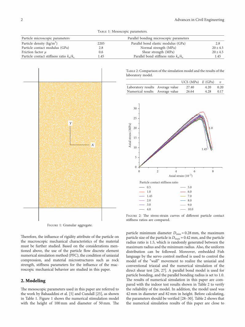
'e mesoscopic parameters used in this paper are referred tothe work by Bahaaddini et al. [5] and Cundall [25], as shownin Table 1. Figure 1 shows the numerical stimulation modelwith the height of 100mm and diameter of 50mm. 'e
particle minimum diameter Dmin� 0.28mm, the maximumparticle size of the particle isDmax � 0.42mm, and the particleradius ratio is 1.5, which is randomly generated between themaximum radius and the minimum radius. Also, the uniformdistribution can be followed. Moreover, embedded Fishlanguage by the servo control method is used to control themodel of the “wall” movement to realize the uniaxial andconventional triaxial and the numerical simulation of thedirect shear test [26, 27]. A parallel bond model is used forparticle bonding, and the parallel bonding radius is set to 1.0.'e results of numerical simulation in this paper are com-pared with the indoor test results shown in Table 2 to verifythe reliability of the model. In addition, the model used was42mm in diameter and 82mm in height. Before calculating,the parameters should be verified [28–30]. Table 2 shows thatthe numerical simulation results of this paper are close to
Table 1: Mesoscopic parameters.
Particle microscopic parameters Parallel bonding microscopic parametersParticle density (kg/m3) 2205 Parallel bond elastic modulus (GPa) 2.8Particle contact modulus (GPa) 2.8 Normal strength (MPa) 20± 4.5Friction factor μ 0.6 Shear strength (MPa) 20± 4.5Particle contact stiffness ratio kn/ks 1.45 Parallel bond stiffness ratio kn/ks 1.45
X
Y
Figure 1: Granular aggregate.
Table 2: Comparison of the simulation model and the results of thelaboratory model.
UCS (MPa) E (GPa) υLaboratory results Average value 27.40 4.20 0.20Numerical results Average value 26.64 4.28 0.17
0 2 4 6 80
5
10
15
20
25
30
1.0A
xial
stre
ss (M
Pa)
Axial strain (10–3)
0.51.01.452.03.04.0
5.06.07.08.09.010.0
Particle contact stiffness ratio
1.45
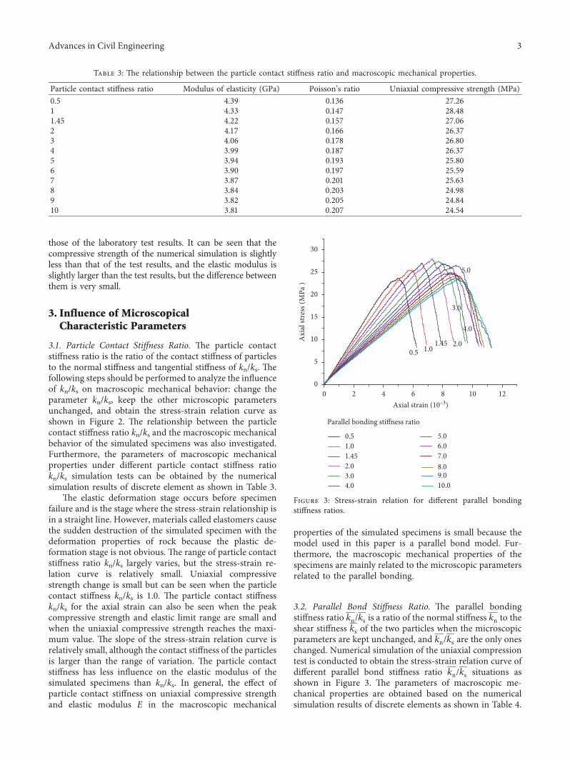
Figure 2: 'e stress-strain curves of different particle contactstiffness ratios are compared.
2 Advances in Civil Engineering
those of the laboratory test results. It can be seen that thecompressive strength of the numerical simulation is slightlyless than that of the test results, and the elastic modulus isslightly larger than the test results, but the difference betweenthem is very small.
3. Influence of MicroscopicalCharacteristic Parameters
3.1. Particle Contact Stiffness Ratio. 'e particle contactstiffness ratio is the ratio of the contact stiffness of particlesto the normal stiffness and tangential stiffness of kn/ks. 'efollowing steps should be performed to analyze the influenceof kn/ks on macroscopic mechanical behavior: change theparameter kn/ks, keep the other microscopic parametersunchanged, and obtain the stress-strain relation curve asshown in Figure 2. 'e relationship between the particlecontact stiffness ratio kn/ks and the macroscopic mechanicalbehavior of the simulated specimens was also investigated.Furthermore, the parameters of macroscopic mechanicalproperties under different particle contact stiffness ratiokn/ks simulation tests can be obtained by the numericalsimulation results of discrete element as shown in Table 3.
'e elastic deformation stage occurs before specimenfailure and is the stage where the stress-strain relationship isin a straight line. However, materials called elastomers causethe sudden destruction of the simulated specimen with thedeformation properties of rock because the plastic de-formation stage is not obvious. 'e range of particle contactstiffness ratio kn/ks largely varies, but the stress-strain re-lation curve is relatively small. Uniaxial compressivestrength change is small but can be seen when the particlecontact stiffness kn/ks is 1.0. 'e particle contact stiffnesskn/ks for the axial strain can also be seen when the peakcompressive strength and elastic limit range are small andwhen the uniaxial compressive strength reaches the maxi-mum value. 'e slope of the stress-strain relation curve isrelatively small, although the contact stiffness of the particlesis larger than the range of variation. 'e particle contactstiffness has less influence on the elastic modulus of thesimulated specimens than kn/ks. In general, the effect ofparticle contact stiffness on uniaxial compressive strengthand elastic modulus E in the macroscopic mechanical
properties of the simulated specimens is small because themodel used in this paper is a parallel bond model. Fur-thermore, the macroscopic mechanical properties of thespecimens are mainly related to the microscopic parametersrelated to the parallel bonding.
3.2. Parallel Bond Stiffness Ratio. 'e parallel bondingstiffness ratio kn/ks is a ratio of the normal stiffness kn to theshear stiffness ks of the two particles when the microscopicparameters are kept unchanged, and kn/ks are the only oneschanged. Numerical simulation of the uniaxial compressiontest is conducted to obtain the stress-strain relation curve ofdifferent parallel bond stiffness ratio kn/ks situations asshown in Figure 3. 'e parameters of macroscopic me-chanical properties are obtained based on the numericalsimulation results of discrete elements as shown in Table 4.
Table 3: 'e relationship between the particle contact stiffness ratio and macroscopic mechanical properties.
Particle contact stiffness ratio Modulus of elasticity (GPa) Poisson’s ratio Uniaxial compressive strength (MPa)0.5 4.39 0.136 27.261 4.33 0.147 28.481.45 4.22 0.157 27.062 4.17 0.166 26.373 4.06 0.178 26.804 3.99 0.187 26.375 3.94 0.193 25.806 3.90 0.197 25.597 3.87 0.201 25.638 3.84 0.203 24.989 3.82 0.205 24.8410 3.81 0.207 24.54
0 2 4 6 8 10 120
5
10
15
20
25
30
5.0
4.0
3.0
2.01.451.0
Axi
al st
ress
(MPa
)
Axial strain (10–3)
0.51.01.452.03.04.0
5.06.07.08.09.010.0
Parallel bonding stiffness ratio
0.5
Figure 3: Stress-strain relation for different parallel bondingstiffness ratios.
Advances in Civil Engineering 3

Before the failure of the specimen, the axial straincorresponding to the peak compressive strength increaseswith the increase in the stiffness ratio kn/ks of the parallelbond. 'e variation range of axial strain is nearly 4mm, andthe elastic limit becomes smaller with the increase in theparallel bond stiffness ratio. 'e peak compressive strengthreached a maximum of 28MPa at the time of parallel bondstiffness ratio 2.0. Conversely, when the parallel bondstiffness ratio is less than 2.0, the uniaxial compressivestrength increases as the parallel bond stiffness ratio in-creases. When the increasing parallel bond stiffness ratio isgreater than 2.0, the uniaxial compressive strength hasslowly small increase. When the parallel bond stiffness ratiois greater than 5.0, the peak compressive strength decreasessignificantly. 'is phenomenon is caused by the gradualincrease in the parallel bond stiffness ratio. In addition, the
parallel bond’s normal stiffness is greater than the tangentialstiffness; specimen “rigid” enhanced by plastic deformationdamage to brittle failure mode change gradually becomea rigid body, and the uniaxial compressive strength de-creases. 'e slope of the stress-strain relation curve beforethe sudden failure also decreases with the increase in theparallel bond stiffness ratio. 'e effect of the parallel bondstiffness on the elastic modulus of the specimens is relativelylarge and inversely proportional to each other. 'is phe-nomenon is caused by the high rigidity of the parallel bondbetween particles. A strong “rigidity” indicates small“elasticity” and small macroscopic elastic modulus.
3.3. Particle Contact Modulus. 'e particle contact modulusEc is the elastic modulus of contact between particles.Certain deformation occurs when the pellet is affected by theforce. Figure 4 shows the stress-strain of the obtained re-lation of particle contact modulus Ec. 'e relationship be-tween the particle contact modulus Ec and the macroscopicmechanical behavior of the simulated specimens is alsodiscussed. In addition, Table 5 shows the parameters ofmacroscopic mechanical properties under different particlecontact modulus Ec simulation tests obtained by the nu-merical simulation results of discrete elements.
Figure 4 shows that the particle contact modulus Ec hasa great influence on the stress-strain relation curve. 'eparticle contact modulus Ec has a great influence on the elasticmodulus of sandstone and is characterized by the increase inthe particle contact modulus Ec, corresponding axial strainfor the peak compressive strength decreases, and the slope ofthe stress-strain relationship curves before damage in-creases. 'is phenomenon is also caused by the increase inthe particle contact modulus Ec which increases the elasticmodulus E of macroscopic materials. 'e uniaxial com-pressive strength has the general increasing trend with theincreasing particle contact modulus Ec, but the amplitude ofincrease is relatively small. Hence, the particle contactmodulus Ec minimally affects the uniaxial compressivestrength, and the variation is not evident.
3.4. Parallel Bond Elastic Modulus. 'e elastic modulus ofthe parallel bond Ec is the elastic modulus of the material
TABLE 4: Relation between the macromechanical properties with different parallel bonding stiffness ratios.
Parallel bonding stiffness ratio Elastic modulus (GPa) Poisson’s ratio Uniaxial compressive strength (MPa)0.5 5.20 0.030 23.731 4.70 0.107 25.511.45 4.22 0.157 27.062 3.90 0.190 28.003 3.52 0.228 27.494 3.26 0.251 26.925 3.07 0.268 26.606 2.93 0.280 24.977 2.81 0.290 24.728 2.72 0.297 24.069 2.64 0.304 23.7310 2.57 0.310 23.38
0 2 4 6 8 100
5
10
15
20
25
30
7.06.0
5.0
4.03.5
2.82.5
2.0 1.5
Axia
l stre
ss (M
Pa)
Axial strain (10–3)
1.01.52.02.52.83.5
4.04.55.06.07.0
Particle contact modulus (GPa)
1.0
Figure 4: Stress-strain relation for different particle contactmoduli.
4 Advances in Civil Engineering

between two particles in each parallel bond model. Figure 5shows the stress-strain relation curve. Table 6 shows theparameters of macroscopic mechanical properties obtainedfrom the numerical simulation results of discrete elements.
Figure 5 also shows that the parallel bonded elasticmodulus greatly influences the stress-strain curve mostnotably with the parallel bond and when the increase in theelastic modulus and uniaxial compressive strength is large.'e elastic modulus of the parallel bond greatly influencesthe uniaxial compressive strength, and the relationshipbetween them is proportional. Before the failure of the testpiece, the axial strain and elastic limit corresponding to thepeak compressive strength decrease with the increase in theelastic modulus of the parallel bond. 'is phenomenon iscaused by the increase in the slope of the stress-strain re-lation curve, which increases the elastic modulus of the
parallel bond. 'erefore, the elastic modulus of the parallelbond that greatly influences the elastic modulus E of thesimulated specimens mainly affects the elastic modulus ofthe parallel bond.
4. Conclusions
(1) 'e range of the particle contact stiffness ratio kn/kslargely varies, but the stress-strain relation curve isrelatively small. Uniaxial compressive strength changeis small. 'e slope of the stress-strain relation curve isrelatively small, although the contact stiffness of theparticles is larger than the range of variation. 'eparticle contact stiffness has less influence on the elasticmodulus of the simulated specimens than kn/ks.
(2) Before the failure of the specimen, the axial straincorresponding to the peak compressive strengthincreases with the increase in the stiffness ratio kn/ksof the parallel bond. Conversely, when the parallelbond stiffness ratio is less than 2.0, the uniaxialcompressive strength increases as the parallel bondstiffness ratio increases. When the increasing parallelbond stiffness ratio is greater than 2.0, the uniaxialcompressive strength has slowly small increase.When the parallel bond stiffness ratio is greater than5.0, the peak compressive strength decreases sig-nificantly. 'e slope of the stress-strain relation
TABLE 5: Relation between the macromechanical properties with different particle contact moduli.
Particle contact modulus GPa) Elastic modulus (GPa) Poisson’s ratio Uniaxial compressive strength (MPa)1 3.09 0.121 24.851.5 3.40 0.130 26.252 3.73 0.141 25.952.5 4.06 0.149 26.322.8 4.22 0.157 27.063.5 4.64 0.170 26.814 4.89 0.180 27.544.5 5.24 0.187 29.155 5.49 0.194 27.536 6.00 0.207 28.447 6.52 0.224 29.86
0 2 4 6 8 10 12 14 160
5
10
15
20
25
30
35
4.55.0
6.07.0
4.03.5
2.82.5 2.0 1.5
Axi
al st
ress
(MPa
)
Axial strain (10–3)
1.01.52.02.52.83.5
4.04.55.06.07.0
Elastic modulus of the parallel bond (GPa)
1.0
Figure 5: Stress-strain relation for different elastic moduli of theparallel bond.
TABLE 6: Relation between the macromechanical properties withdifferent elastic moduli of the parallel bond.
Elastic modulus ofthe parallel bond(GPa)
Elasticmodulus(GPa)
Poisson’sratio
Uniaxialcompressive
strength (MPa)1 2.49 0.238 32.141.5 3.02 0.200 30.282 3.50 0.178 28.822.5 4.02 0.158 27.392.8 4.22 0.157 27.063.5 4.83 0.146 26.734 5.25 0.140 25.374.5 5.67 0.135 25.125 6.09 0.132 24.616 6.92 0.126 22.857 7.74 0.123 22.59
Advances in Civil Engineering 5

curve before the sudden failure also decreases withthe increase in the parallel bond stiffness ratio.
(3) 'e particle contact modulus Ec has a great influenceon the elastic modulus of sandstone and is charac-terized by the increase in particle contact modulus Ec,corresponding axial strain for the peak compressivestrength decreases, and the slope of the stress-strainrelationship curves before damage increases. 'euniaxial compressive strength has the general in-creasing trend with the increasing particle contactmodulus Ec, but the amplitude of increase is relativelysmall.
(4) 'e elastic modulus of the parallel bond greatly in-fluences the uniaxial compressive strength, and therelationship between them is proportional. Before thefailure of the test piece, the axial strain and elastic limitcorresponding to the peak compressive strength de-creases with the increase in the elastic modulus of theparallel bond.
Data Availability
'e data used to support the findings of this study areavailable from the corresponding author upon request.
Conflicts of Interest
'e authors declare no conflicts of interest.
References
[1] S. H. Chong, J. W. Kim, and G. C. Cho, “Rock mass dynamictest apparatus for estimating the strain-dependent dynamicproperties of jointed rock masses,” Geotechnical TestingJournal, vol. 37, no. 2, pp. 311–318, 2014.
[2] Y. J. Hou, D. L. Zhang, and F. L. Guo, “Influences of supporton mechanical property of rock in water-containing tunnel,”Journal of Central South University, vol. 41, no. 3, pp. 1152–1157, 2010.
[3] W. Liang, C. Yang, Y. Zhao, M. B. Dusseault, and J. Liu,“Experimental investigation of mechanical properties ofbedded salt rock,” International Journal of Rock Mechanicsand Mining Sciences, vol. 44, no. 3, pp. 400–411, 2007.
[4] Q. Z. Zhang, H. S. Jang, D. S. Bae, G. Y. Kim, and B. A. Jang,“Empirical rock mechanical site-descriptive modeling(RMSDM) for the Korea Atomic Energy Research InstituteUnderground Research Tunnel (KURT),” EnvironmentalEarth Sciences, vol. 75, no. 10, p. 860, 2016.
[5] M. Bahaaddini, G. Sharrock, and B. K. Hebblewhite, “Nu-merical investigation of the effect of joint geometrical pa-rameters on the mechanical properties of a non-persistentjointed rock mass under uniaxial compression,” Computersand Geotechnics, vol. 49, no. 20, pp. 206–225, 2013.
[6] X. Ding, L. Zhang, H. Zhu, and Q. Zhang, “Effect of modelscale and particle size distribution on PFC3D simulationresults,” Rock Mechanics and Rock Engineering, vol. 47, no. 6,pp. 2139–2156, 2014.
[7] R.-h. Cao and H. Lin, “Experimental and numerical study offailure behavior and energy mechanics of rock-like materialscontaining multiple joints,”Advances inMaterials Science andEngineering, vol. 2017, Article ID 6460150, 17 pages, 2017.
[8] X. Fan, P. H. S. W. Kulatilake, X. Chen, and P. Cao, “Crackinitiation stress and strain of jointed rock containing multi-cracks under uniaxial compressive loading: a particle flowcode approach,” Journal of Central South University, vol. 22,no. 2, pp. 638–645, 2015.
[9] J. W. Park and J. J. Song, “Numerical simulation of a directshear test on a rock joint using a bonded-particle model,”International Journal of Rock Mechanics and Mining Sciences,vol. 46, no. 8, pp. 1315–1328, 2009.
[10] T. J. Cui, M. A. Yun-Dong, and L. G. Wang, “Blasting processsimulation and stability study of an open mine slope based onPFC3D,” Applied Mathematics and Mechanics, vol. 35, no. 7,pp. 759–767, 2014.
[11] D. D. Tannant and C. Wang, “'in tunnel liners modelledwith particle flow code,” Engineering Computations, vol. 21,no. 2, pp. 318–342, 2013.
[12] B. K. Mishra, “A review of computer simulation of tumblingmills by the discrete element method: part II—practical ap-plications,” International Journal of Mineral Processing,vol. 71, no. 1, pp. 73–93, 2003.
[13] H. Kruggel-Emden, E. Simsek, S. Rickelt, S. Wirtz, andV. Scherer, “Review and extension of normal force models forthe discrete element method,” Powder Technology, vol. 171,no. 3, pp. 157–173, 2007.
[14] D. He and Y. Cheng, “Numerical simulation for mechanicalbehavior of asphalt pavement with graded aggregate base,”Advances in Civil Engineering, vol. 2018, Article ID 1404731,9 pages, 2018.
[15] H. Lin, W. Xiong, and Q. Yan, “'ree-dimensional effect oftensile strength in the standard Brazilian test consideringcontact length,” Geotechnical Testing Journal, vol. 39, no. 1,pp. 137–143, 2016.
[16] B. Yang, Y. Jiao, and S. Lei, “A study on the effects of micro-parameters on macroproperties for specimens created bybonded particles,” Engineering Computations, vol. 23, no. 6,pp. 607–631, 2006.
[17] M. Bahaaddini, G. Sharrock, and B. K. Hebblewhite, “Numericaldirect shear tests to model the shear behaviour of rock joints,”Computers and Geotechnics, vol. 51, no. 51, pp. 101–115, 2013.
[18] R. Cao, P. Cao, H. Lin, and X. Fan, “Experimental and nu-merical study of the failure process and energy mechanisms ofrock-like materials containing cross un-persistent joints un-der uniaxial compression,” PLoS One, vol. 12, no. 12, ArticleID e0188646, 2017.
[19] H. Huang and E. Detournay, “Discrete element modeling oftool-rock interaction II: rock indentation,” International Journalfor Numerical and Analytical Methods in Geomechanics, vol. 37,no. 13, pp. 1913–1929, 2013.
[20] J. Hadjigeorgiou, K. Esmaieli, andM. Grenon, “Stability analysisof vertical excavations in hard rock by integrating a fracturesystem into a PFC model,” Tunnelling and Underground SpaceTechnology, vol. 24, no. 3, pp. 296–308, 2009.
[21] Z. Liu, N. Zhou, and J. Zhang, “Random gravel model andparticle flow based numerical biaxial test of solid backfill ma-terials,” International Journal of Mining Science and Technology,vol. 23, no. 4, pp. 463–467, 2013.
[22] S. Utili and R. Nova, “DEM analysis of bonded granulargeomaterials,” International Journal for Numerical and An-alytical Methods in Geomechanics, vol. 32, no. 17, pp. 1997–2031, 2008.
[23] G. Yan, H. S. Yu, and G. Mcdowell, “Simulation of granularmaterial behaviour using DEM,” Procedia Earth and Plane-tary Science, vol. 1, no. 1, pp. 598–605, 2009.
6 Advances in Civil Engineering

[24] J. Liu, P. Cao, and D. Han, “'e influence of confining stresson optimum spacing of TBM cutters for cutting granite,”International Journal of Rock Mechanics and Mining Sciences,vol. 88, pp. 165–174, 2016.
[25] P. Cundall, “A computer model for simulating progressivelarge scale movement in block rock systems,” in Proceedings ofthe International Symposium on Rock Mechanics, pp. 11–18,Nancy, France, October 1971.
[26] J. Yoon, “Application of experimental design and optimiza-tion to PFC model calibration in uniaxial compressionsimulation,” International Journal of Rock Mechanics andMining Sciences, vol. 44, no. 6, pp. 871–889, 2007.
[27] A. S. Tawadrous, D. Degagne, M. Pierce, and D. Mas Ivars,“Prediction of uniaxial compression PFC3D model micro-properties using artificial neural networks,” International Jour-nal for Numerical and Analytical Methods in Geomechanics,vol. 33, no. 18, pp. 1953–1962, 2009.
[28] S. D. A. Kumari and T. G. Sitharam, “Effect of aspect ratio on themonotonic shear behaviour: micromechanical interpretations,”Geotechnical and Geological Engineering, vol. 31, no. 5,pp. 1543–1553, 2013.
[29] X. Wang, Z. J. Wen, and Y. J. Jiang, “Time–space effect ofstress field and damage evolution law of compressed coal-rock,” Geotechnical and Geological Engineering, vol. 34, no. 6,pp. 1–8, 2016.
[30] D. Wijewickreme, A. Dabeet, and P. Byrne, “Some observa-tions on the state of stress in the direct simple shear test using3D discrete element analysis,” Geotechnical Testing Journal,vol. 36, no. 2, pp. 292–299, 2013.
Advances in Civil Engineering 7

International Journal of
AerospaceEngineeringHindawiwww.hindawi.com Volume 2018
RoboticsJournal of
Hindawiwww.hindawi.com Volume 2018
Hindawiwww.hindawi.com Volume 2018
Active and Passive Electronic Components
VLSI Design
Hindawiwww.hindawi.com Volume 2018
Hindawiwww.hindawi.com Volume 2018
Shock and Vibration
Hindawiwww.hindawi.com Volume 2018
Civil EngineeringAdvances in
Acoustics and VibrationAdvances in
Hindawiwww.hindawi.com Volume 2018
Hindawiwww.hindawi.com Volume 2018
Electrical and Computer Engineering
Journal of
Advances inOptoElectronics
Hindawiwww.hindawi.com
Volume 2018
Hindawi Publishing Corporation http://www.hindawi.com Volume 2013Hindawiwww.hindawi.com
The Scientific World Journal
Volume 2018
Control Scienceand Engineering
Journal of
Hindawiwww.hindawi.com Volume 2018
Hindawiwww.hindawi.com
Journal ofEngineeringVolume 2018
SensorsJournal of
Hindawiwww.hindawi.com Volume 2018
International Journal of
RotatingMachinery
Hindawiwww.hindawi.com Volume 2018
Modelling &Simulationin EngineeringHindawiwww.hindawi.com Volume 2018
Hindawiwww.hindawi.com Volume 2018
Chemical EngineeringInternational Journal of Antennas and
Propagation
International Journal of
Hindawiwww.hindawi.com Volume 2018
Hindawiwww.hindawi.com Volume 2018
Navigation and Observation
International Journal of
Hindawi
www.hindawi.com Volume 2018
Advances in
Multimedia
Submit your manuscripts atwww.hindawi.com