influence of tool steel carbide orientation on sliding wear620672/fulltext01.pdf · influence of...
TRANSCRIPT
Influence of tool steel carbide orientation on sliding wear
Inverkan av karbidorientering hos ett verktygsstål på glidande slitage
Johanna Meseret Berhe Larsson
Faculty of health, science and technology
Degree project for master of science in engineering, mechanical engineering
30 credit points
Supervisor: Anders Gåård
Examiner: Jens Bergström
Date: Spring semester 2012, 2013-05-03
Serial number:
Influence of tool steel carbide orientation on sliding wear
1
Abstract
For SMF industry, galling of tool in SMF operation during forming of stainless steel is a major concern,
this increase the interest to study influence of tool microstructure on galling. In the present work, ingot
cast AISI D2 were evaluated concerning wear mechanisms and critical sliding distance against
austenitic stainless steel sheet in lubricated sliding condition at different contact pressures using a slider-
on-flat-surface (SOFS) tribometer for carbide phases oriented in three different directions. At the initial
sliding abrasive scratching by protruding carbide phases were the initial wear mechanism. Further
sliding led to growth of sheet material transfer with formation of lump covering of the tool surfaces both
carbide phase and metal matrix. AISI D 2 tool with protruding carbide that has relatively evenly
distributed small round shaped carbides and higher volume fraction of carbide had a positive influence
in terms of galling at low normal load and has shown best tool performance.
Influence of tool steel carbide orientation on sliding wear
2
Acknowledgement
I forward my deepest gratitude to all who have been with me and unselfishly shared with me their
knowledge during this thesis work. Primarily I am genuinely thankful to my supervisor Anders Gåård
for his experienced guidance, advice and contribution towards the successful completion of this thesis.
Secondly, I would like to thank Patrik Karlsson for his humble sprit along with the invaluable advice
on the books and articles I needed to read as well as SEM and SOFS testing. In addition, I thank Anna
Persson and Christer Burman for their help in the Metallurgy lab and their experienced guidance. It was
a pleasure doing this thesis with you all.
Finally, I would like to thank my husband Mikael for his continuous support and love.
Influence of tool steel carbide orientation on sliding wear
3
Table of Contents Abstract .................................................................................................................................... 1
1 Introduction .................................................................................................................. 5
1.1 Sheet metal forming ..................................................................................................... 6
1.1.1 SMF processes .............................................................................................................. 6
1.2 SMF system components ............................................................................................. 7
1.2.1 Sheet materials ............................................................................................................. 7
1.2.2 Tool steel materials .................................................................................................... 10
1.2.2.1 Tool Steel Production ................................................................................................. 11
1.2.2.2 Tool Steel Microstructural Composition .................................................................... 12
1.3 Lubrication in SMF .................................................................................................... 13
2 Wear and wear mode in SMF ..................................................................................... 15
2.1 Wear ........................................................................................................................... 15
2.1.1 Adhesive wear ............................................................................................................ 15
2.1.2 Abrasive scratching .................................................................................................... 16
2.1.3 Galling ........................................................................................................................ 17
3 Galling test ................................................................................................................. 19
3.1 Tribological testing methods of galling ..................................................................... 19
3.2 The experiment ........................................................................................................... 19
3.2.1 Slider on flat surface (SOFS) tribometer and test parameters .................................... 19
3.2.2 Materials and volume fraction of carbides ................................................................. 20
4 Results ........................................................................................................................ 24
4.1 Friction and galling criteria ........................................................................................ 24
4.1.1 Short sliding test ......................................................................................................... 25
4.1.1.1 Wear Mechanisms at short sliding distance ............................................................... 25
4.1.2 Long sliding test ......................................................................................................... 27
4.2 Volume fraction .......................................................................................................... 29
5 Discussion .................................................................................................................. 30
6 Conclusion .................................................................................................................. 33
Influence of tool steel carbide orientation on sliding wear
4
Bibliography ........................................................................................................................... 34
Influence of tool steel carbide orientation on sliding wear
5
1 Introduction
Transfer of material between the contacting surfaces is the main problem in many tribological sliding
contacts such as in SMF since this depends on the character of tribosystem and contact condition.
Therefore, it is the most controlling parameter in SMF as it affects both product surface quality and
destruction of the tool. Tool material in SMF has high economic importance, since in order to change
the tool the productions have to stop. Hence, selection of tool steel for SMF is based on the
requirements of tool life. The main factor affecting tool life is wear; in SMF the wear process is mostly
related to adhesive wear in which the sheet material is transferred to the tool surface. This often called
galling. Galling is a process consisting of different stages resulting in transfer of sheet material to the
tools surface. The transferred material leads to scratching of subsequently formed sheets and high
friction [1-3].
A lot of effort has been done on investigation of mechanisms related to galling in SMF processes. One
of the frequently occurring discussions in scientific papers is the effect of tool microstructure. For
instance, powder metallurgy (PM) tool steels, and particularly nitrogen alloyed, gained a lot of interest
since it has high galling resistance due to homogeneously and densely distributed carbonitride particles.
Therefore, galling resistance has proven significantly improved compared to conventionally ingot cast
tool steels. Nevertheless, ingot cast D2 type tool steels are still in use largely in SMF. These materials
have a heterogeneous microstructure with relatively large elongated carbides [1] [2] [4].
Many studies have been done on identifying mechanisms of the initial sheet material transfer. However,
the mechanisms are still unclear and the initial phase has been attributed both to adhesive wear of the
sheet to the tool steel matrix as well as scratching of the sheet by protruding carbides.
Influence of tool steel carbide orientation on sliding wear
6
1.1 Sheet metal forming
1.1.1 SMF processes
The SMF process is an important group of metal forming processes for instance in automotive
applications; and it consists of a broad range of processes. The metal sheet is plastically deformed into a
final shape by a tool.
A typical SMF processes in general consists of a blank, a die on which the blank is clamp that has the
shape of the final product and a punch that deforms the blank into the die. These tools are operated by a
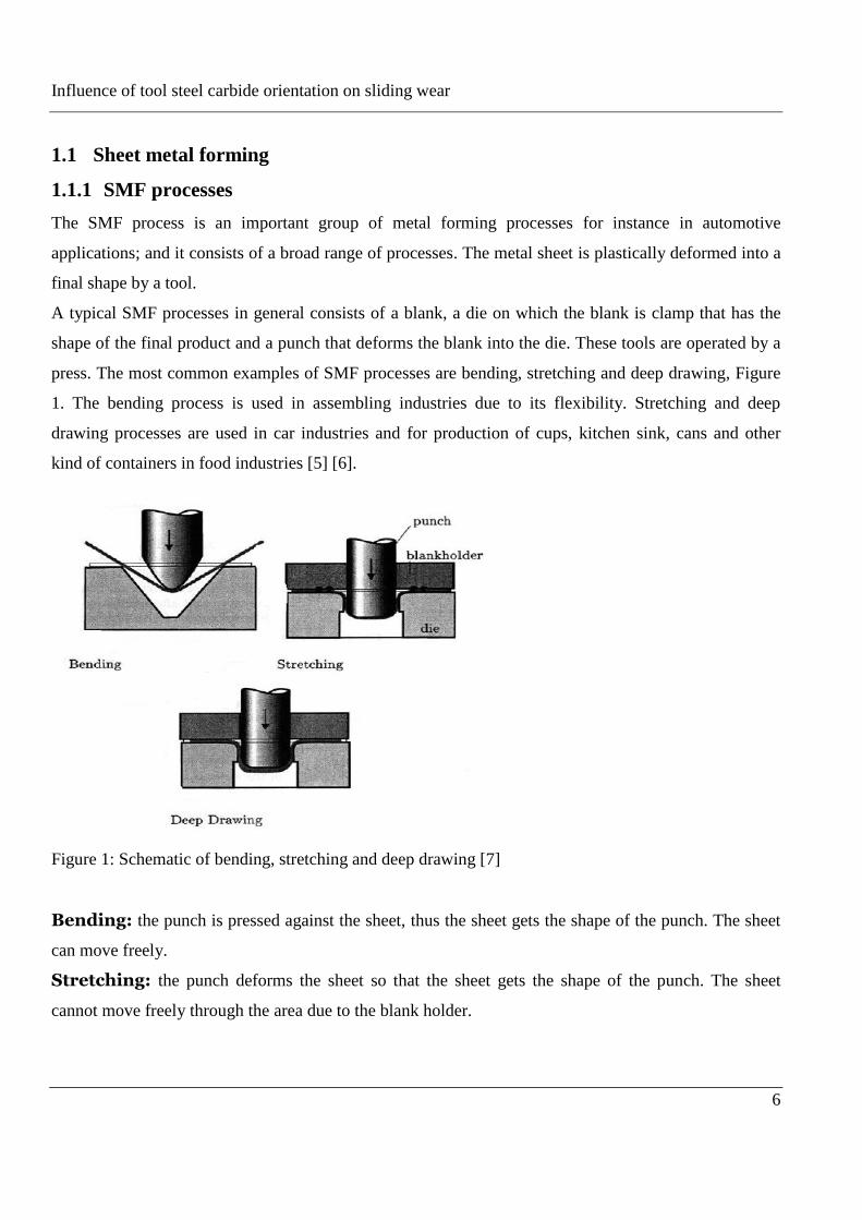
press. The most common examples of SMF processes are bending, stretching and deep drawing, Figure
1. The bending process is used in assembling industries due to its flexibility. Stretching and deep
drawing processes are used in car industries and for production of cups, kitchen sink, cans and other
kind of containers in food industries [5] [6].
Figure 1: Schematic of bending, stretching and deep drawing [7]
Bending: the punch is pressed against the sheet, thus the sheet gets the shape of the punch. The sheet
can move freely.
Stretching: the punch deforms the sheet so that the sheet gets the shape of the punch. The sheet
cannot move freely through the area due to the blank holder.
Influence of tool steel carbide orientation on sliding wear
7
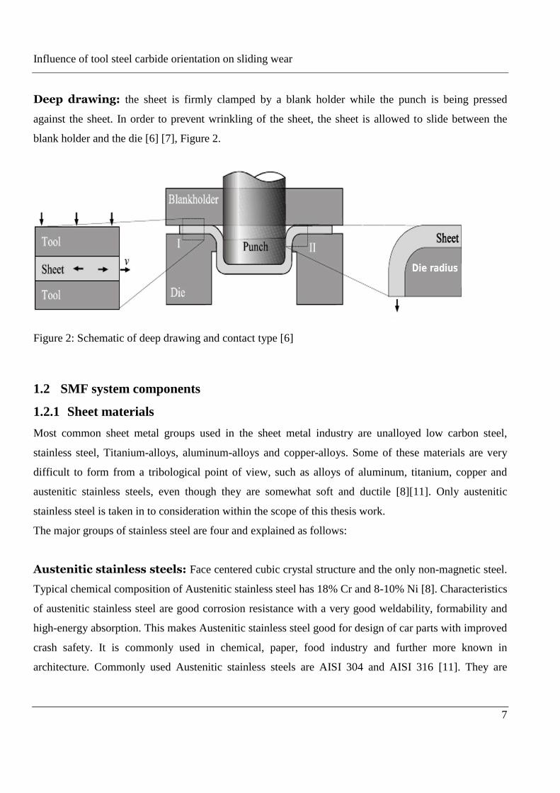
Deep drawing: the sheet is firmly clamped by a blank holder while the punch is being pressed
against the sheet. In order to prevent wrinkling of the sheet, the sheet is allowed to slide between the
blank holder and the die [6] [7], Figure 2.
Figure 2: Schematic of deep drawing and contact type [6]
1.2 SMF system components
1.2.1 Sheet materials
Most common sheet metal groups used in the sheet metal industry are unalloyed low carbon steel,
stainless steel, Titanium-alloys, aluminum-alloys and copper-alloys. Some of these materials are very
difficult to form from a tribological point of view, such as alloys of aluminum, titanium, copper and
austenitic stainless steels, even though they are somewhat soft and ductile [8][11]. Only austenitic
stainless steel is taken in to consideration within the scope of this thesis work.
The major groups of stainless steel are four and explained as follows:
Austenitic stainless steels: Face centered cubic crystal structure and the only non-magnetic steel.
Typical chemical composition of Austenitic stainless steel has 18% Cr and 8-10% Ni [8]. Characteristics
of austenitic stainless steel are good corrosion resistance with a very good weldability, formability and
high-energy absorption. This makes Austenitic stainless steel good for design of car parts with improved
crash safety. It is commonly used in chemical, paper, food industry and further more known in
architecture. Commonly used Austenitic stainless steels are AISI 304 and AISI 316 [11]. They are
Influence of tool steel carbide orientation on sliding wear
8
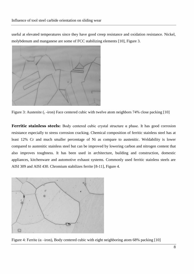
useful at elevated temperatures since they have good creep resistance and oxidation resistance. Nickel,
molybdenum and manganese are some of FCC stabilizing elements [10], Figure 3.
Figure 3: Austenite (ᵧ -iron) Face centered cubic with twelve atom neighbors 74% close packing [10]
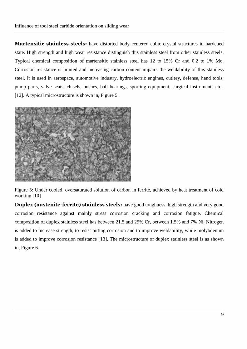
Ferritic stainless steels: Body centered cubic crystal structure α phase. It has good corrosion
resistance especially to stress corrosion cracking. Chemical composition of ferritic stainless steel has at
least 12% Cr and much smaller percentage of Ni as compare to austenitic. Weldability is lower
compared to austenitic stainless steel but can be improved by lowering carbon and nitrogen content that
also improves toughness. It has been used in architecture, building and construction, domestic
appliances, kitchenware and automotive exhaust systems. Commonly used ferritic stainless steels are
AISI 309 and AISI 430. Chromium stabilizes ferrite [8-11], Figure 4.
Figure 4: Ferrite (α –iron), Body centered cubic with eight neighboring atom 68% packing [10]
Influence of tool steel carbide orientation on sliding wear
9
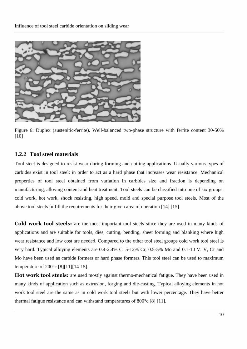
Martensitic stainless steels: have distorted body centered cubic crystal structures in hardened
state. High strength and high wear resistance distinguish this stainless steel from other stainless steels.
Typical chemical composition of martensitic stainless steel has 12 to 15% Cr and 0.2 to 1% Mo.
Corrosion resistance is limited and increasing carbon content impairs the weldability of this stainless
steel. It is used in aerospace, automotive industry, hydroelectric engines, cutlery, defense, hand tools,
pump parts, valve seats, chisels, bushes, ball bearings, sporting equipment, surgical instruments etc..
[12]. A typical microstructure is shown in, Figure 5.
Figure 5: Under cooled, oversaturated solution of carbon in ferrite, achieved by heat treatment of cold
working [10]
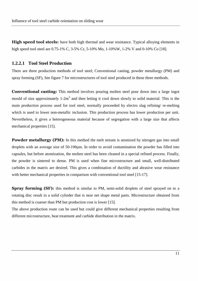
Duplex (austenite-ferrite) stainless steels: have good toughness, high strength and very good
corrosion resistance against mainly stress corrosion cracking and corrosion fatigue. Chemical
composition of duplex stainless steel has between 21.5 and 25% Cr, between 1.5% and 7% Ni. Nitrogen
is added to increase strength, to resist pitting corrosion and to improve weldability, while molybdenum
is added to improve corrosion resistance [13]. The microstructure of duplex stainless steel is as shown
in, Figure 6.
Influence of tool steel carbide orientation on sliding wear
10
Figure 6: Duplex (austenitic-ferrite). Well-balanced two-phase structure with ferrite content 30-50%
[10]
1.2.2 Tool steel materials
Tool steel is designed to resist wear during forming and cutting applications. Usually various types of
carbides exist in tool steel; in order to act as a hard phase that increases wear resistance. Mechanical
properties of tool steel obtained from variation in carbides size and fraction is depending on
manufacturing, alloying content and heat treatment. Tool steels can be classified into one of six groups:
cold work, hot work, shock resisting, high speed, mold and special purpose tool steels. Most of the
above tool steels fulfill the requirements for their given area of operation [14] [15].
Cold work tool steels: are the most important tool steels since they are used in many kinds of
applications and are suitable for tools, dies, cutting, bending, sheet forming and blanking where high
wear resistance and low cost are needed. Compared to the other tool steel groups cold work tool steel is
very hard. Typical alloying elements are 0.4-2.4% C, 5-12% Cr, 0.5-5% Mo and 0.1-10 V. V, Cr and
Mo have been used as carbide formers or hard phase formers. This tool steel can be used to maximum
temperature of 200°c [8][11][14-15].
Hot work tool steels: are used mostly against thermo-mechanical fatigue. They have been used in
many kinds of application such as extrusion, forging and die-casting. Typical alloying elements in hot
work tool steel are the same as in cold work tool steels but with lower percentage. They have better
thermal fatigue resistance and can withstand temperatures of 800°c [8] [11].
Influence of tool steel carbide orientation on sliding wear
11
High speed tool steels: have both high thermal and wear resistance. Typical alloying elements in
high speed tool steel are 0.75-1% C, 3-5% Cr, 5-10% Mo, 1-10%W, 1-2% V and 0-10% Co [18].
1.2.2.1 Tool Steel Production
There are three production methods of tool steel; Conventional casting, powder metallurgy (PM) and
spray forming (SF), See figure 7 for microstructures of tool steel produced in these three methods.
Conventional casting: This method involves pouring molten steel pour down into a large ingot
mould of size approximately 1-2m3 and then letting it cool down slowly to solid material. This is the
main production process used for tool steel, normally proceeded by electro slag refining/ re-melting
which is used to lower non-metallic inclusion. This production process has lower production per unit.
Nevertheless, it gives a heterogeneous material because of segregation with a large size that affects
mechanical properties [15].
Powder metallurgy (PM): In this method the melt stream is atomized by nitrogen gas into small
droplets with an average size of 50-100μm. In order to avoid contamination the powder has filled into
capsules, but before atomization, the molten steel has been cleaned in a special refined process. Finally,
the powder is sintered to dense. PM is used when fine microstructure and small, well-distributed
carbides in the matrix are desired. This gives a combination of ductility and abrasive wear resistance
with better mechanical properties in comparison with conventional tool steel [15-17].
Spray forming (SF): this method is similar to PM, semi-solid droplets of steel sprayed on to a
rotating disc result in a solid cylinder that is near net shape metal parts. Microstructure obtained from
this method is coarser than PM but production cost is lower [15].
The above production route can be used but could give different mechanical properties resulting from
different microstructure, heat treatment and carbide distribution in the matrix.
Influence of tool steel carbide orientation on sliding wear
12
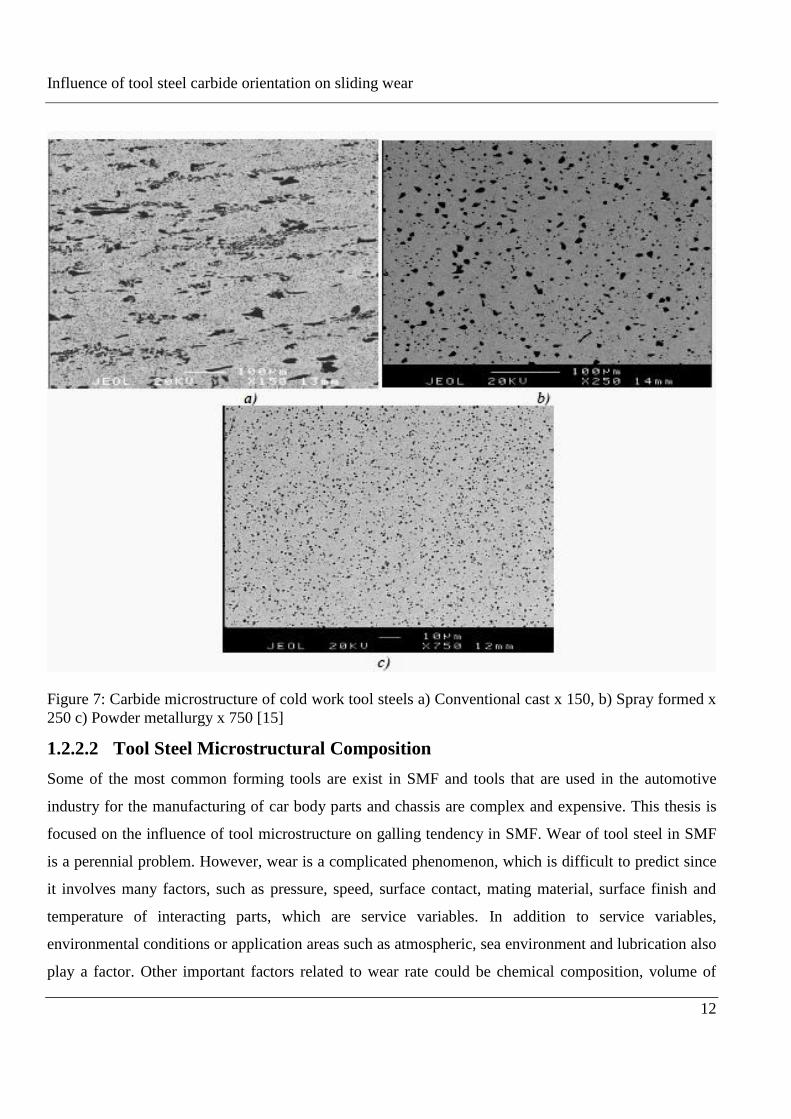
Figure 7: Carbide microstructure of cold work tool steels a) Conventional cast x 150, b) Spray formed x
250 c) Powder metallurgy x 750 [15]
1.2.2.2 Tool Steel Microstructural Composition
Some of the most common forming tools are exist in SMF and tools that are used in the automotive
industry for the manufacturing of car body parts and chassis are complex and expensive. This thesis is
focused on the influence of tool microstructure on galling tendency in SMF. Wear of tool steel in SMF
is a perennial problem. However, wear is a complicated phenomenon, which is difficult to predict since
it involves many factors, such as pressure, speed, surface contact, mating material, surface finish and
temperature of interacting parts, which are service variables. In addition to service variables,
environmental conditions or application areas such as atmospheric, sea environment and lubrication also
play a factor. Other important factors related to wear rate could be chemical composition, volume of
Influence of tool steel carbide orientation on sliding wear
13
different microstructural constituents such as carbide and hard phase particles and the matrix structure.
From the above factors mentioned, microstructures have a dominant influence on the surface life of
machine components [8] [18].
1.3 Lubrication in SMF
Friction and lubrication involves many different tribological subjects. The processes are very complex.
High temperature in contacting surface is caused by the energy absorbed during the friction between two
surfaces in contact that are in relative motion. This high temperature is dependent on the lubrication
between the two mating surfaces. A lubricant functions between the sliding surfaces, forming a layer of
material with lower shear strength than the surfaces themselves. Lubricants prevent asperity contact and
reduce the strength of junctions formed; in some cases, it totally separates surfaces and no asperity
junctions have formed. Hence, lubricant always reduces sliding wear rate. Lubricants in SMF plays an
important role by separating the contacting work piece and tool surface and this reduces the possibility
of galling. There are various types of lubrication modes. A discussion is useful to be able to distinguish
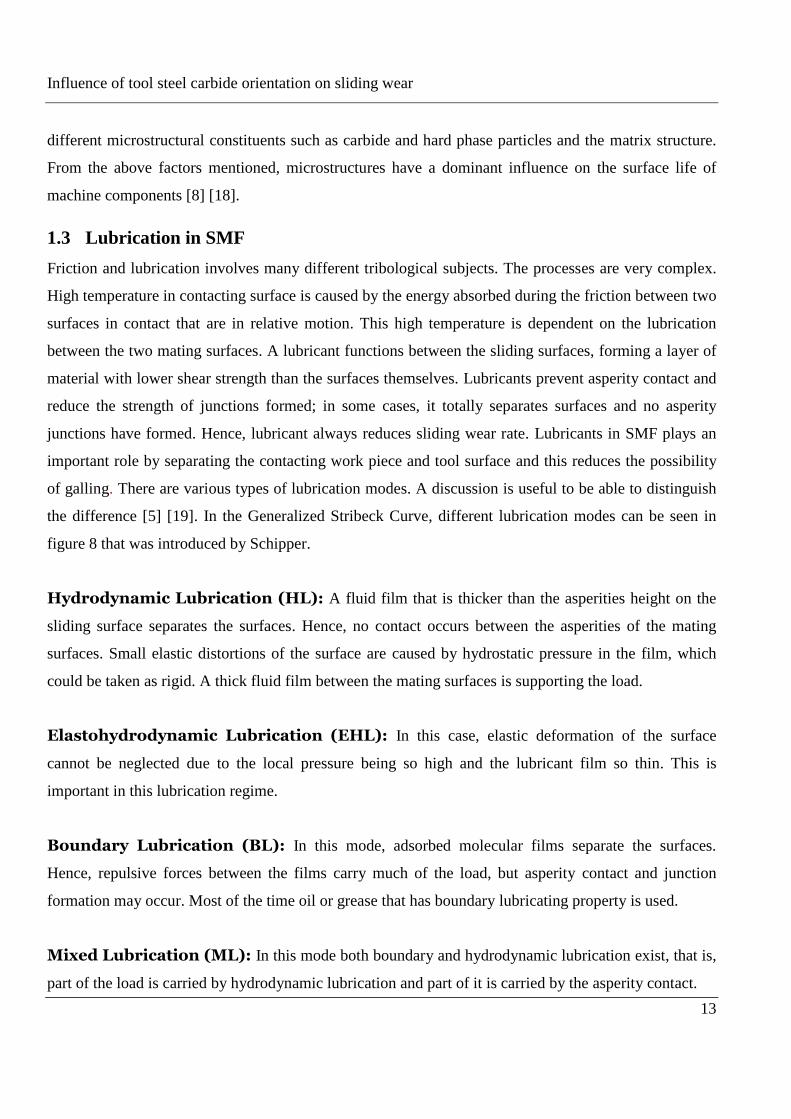
the difference [5] [19]. In the Generalized Stribeck Curve, different lubrication modes can be seen in
figure 8 that was introduced by Schipper.
Hydrodynamic Lubrication (HL): A fluid film that is thicker than the asperities height on the
sliding surface separates the surfaces. Hence, no contact occurs between the asperities of the mating
surfaces. Small elastic distortions of the surface are caused by hydrostatic pressure in the film, which
could be taken as rigid. A thick fluid film between the mating surfaces is supporting the load.
Elastohydrodynamic Lubrication (EHL): In this case, elastic deformation of the surface
cannot be neglected due to the local pressure being so high and the lubricant film so thin. This is
important in this lubrication regime.
Boundary Lubrication (BL): In this mode, adsorbed molecular films separate the surfaces.
Hence, repulsive forces between the films carry much of the load, but asperity contact and junction
formation may occur. Most of the time oil or grease that has boundary lubricating property is used.
Mixed Lubrication (ML): In this mode both boundary and hydrodynamic lubrication exist, that is,
part of the load is carried by hydrodynamic lubrication and part of it is carried by the asperity contact.
Influence of tool steel carbide orientation on sliding wear
14
Figure 8: Generalized Stribeck Curve, Dimensionless lubrication number L= ηv/ (pm Ra) introduced by
Schipper, η lubricant inlet viscosity, v velocity, pm contact pressure, Ra centre line average roughness
[5][11]
Lubricant in SMF plays an important role by separating the contacting work piece and tool surface. In
SMF process, the lubrication mode is that of boundary or a part mixed, hence despite the presence of
lubricant, direct contact between work piece and tool surface can occur due to lubricant film break
down. This results in pick-up of work piece material to the tool surface. This is pronounced especially
when forming tribologically difficult materials such as stainless steel [11] [20].
Since the primary aim of this thesis is to investigate influence of tool steel microstructure on galling,
rather than lubrication, more emphasis will given to adhesion and galling mechanism of sheet material
on tool steel and investigated with SOFS equipment.
Influence of tool steel carbide orientation on sliding wear
15
2 Wear and wear mode in SMF
2.1 Wear
The relative motion of one solid surface over another is essential for the functioning of many kinds of
artificial and natural mechanisms. According to Hutchings (1992), tribology is defined as ‘the science
and technology of interacting surfaces in relative motion’ and embraces the study of friction, wear and
lubrication. Wear is a removal of material from the operating surfaces due to relative motion of the two
solid surfaces from one of or two moving surfaces [19]. Different wear mechanisms rarely exist
distinctly. In reality, the various wear mechanisms occur simultaneously and usually influence each
other in a very complex way that can make predicting wear processes very difficult. In SMF wear can
cause volume loss of the tool or the sheet. A decisive factor for tool performance in the SMF industry
are wear and surface damage such as adhesion and ploughing of sheet material. There are common wear
mechanisms in SMF that could be adhesive and abrasive wear, particularly in SMF. Surface damage can
occur due to galling, which is wear processes associated with adhesive wear [4] [6] [8] [11].
2.1.1 Adhesive wear
Sometimes the term adhesive wear has used to indicate sliding wear, but this could lead to
misunderstanding. Even though in sliding wear, adhesion plays an important role; this is not usually the
only chemical and physical process that is involved in sliding wear. Hence as a general preference, we
use the term sliding wear. In adhesive wear, the two mating surfaces under load adhere together.
Subsequently, detachment of one of the mating faces causes loss of material. Removal of material is lost
through lumps from one or both of the mating surfaces, either temporarily or permanently, attached to
one of the surface. Part of the weaker metal is removed when the welded asperity junction is shared for
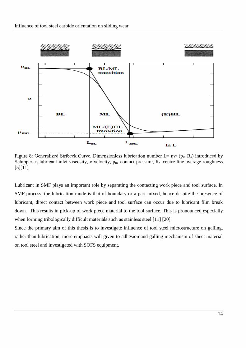
dissimilar metals [19], See figure 9.
Influence of tool steel carbide orientation on sliding wear
16
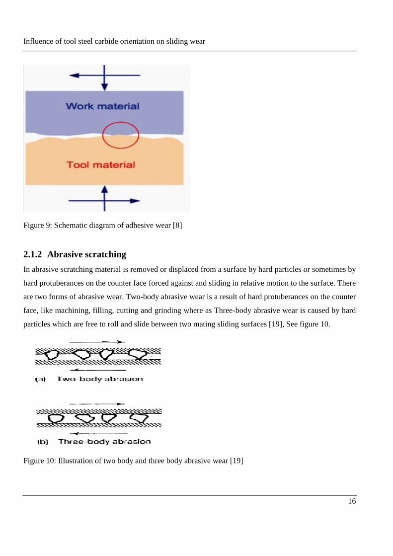
Figure 9: Schematic diagram of adhesive wear [8]
2.1.2 Abrasive scratching
In abrasive scratching material is removed or displaced from a surface by hard particles or sometimes by
hard protuberances on the counter face forced against and sliding in relative motion to the surface. There
are two forms of abrasive wear. Two-body abrasive wear is a result of hard protuberances on the counter
face, like machining, filling, cutting and grinding where as Three-body abrasive wear is caused by hard
particles which are free to roll and slide between two mating sliding surfaces [19], See figure 10.
Figure 10: Illustration of two body and three body abrasive wear [19]
Influence of tool steel carbide orientation on sliding wear
17
2.1.3 Galling
A known failure reason in the SMF industry is galling. Galling is usually described differently in many
scientific papers. In the context of metal forming, Galling is associated with the tendency for lubricant
film breakdown resulting in pick-up of sheet material by the tool surface and subsequent scoring
(=severe scratching) of the work piece surface. The surface qualities of the products are affected by
galling. This results in replacement or maintenance of the tool before preceding production. Delaying or
avoiding galling mechanisms is therefore of high industrial importance [3] [21].
Galling has been described as a form of severe adhesive wear. In adhesive wear, the two mating surfaces
under load adhere together. Subsequently, detachment of one of the mating faces causes loss of material.
Material is lost through lumps from one or both of the mating surfaces either temporarily or
permanently. During relative motion, applying sufficient loads destroys the oxide layer covering
asperities of metal; which can allow metal-to-metal contact. Strong adhesive bonds may form over a
large area; which happens in high stress and poor lubrication conditions [1] [3] [19]. Work hardening
occurs on the transferred material under continued sliding. The hardened transferred materials perform
as higher asperities and deform the sheet surface. This makes it pick up even more material and the
lumps will grow. At the beginning of sliding, the transfer material is small, but subsequent sliding
makes the material pick up grow and become visible on a macroscopic scale. Finally, the sheet material
shows multiple scratches and the coefficient of friction increases and becomes unstable. The relative
motion comes to end ultimately to seizure, due to the adhesive forces and the change in geometry [3]
[22-23]. The result is galling of the work piece.
According to the ASTM standard, galling is defined as a form of surface damage arising between sliding
solids and distinguished by macroscopic, usually localized, roughening and creation of protrusions
above the original surface [24]. However, according to [11], “galling mechanisms in SMF operation can
be divided into three phases; initiation, lump growth and severe scratching or seizure, the initiation of
material transfer is proposed to occur at tool surface defects like grinding marks or carbides and is rather
insensitive to material combinations and lubrication. The second phase stresses the accumulative nature
of galling: lumps on the tool surface grow as a function of the amount of products formed. Lump
initiation and lump growths are controlled by the probability of wedge formation in the contact between
a tool surface asperity and the flattened sheet asperities. In turn, wedge formation can be predicted based
on the geometry of asperity (or lump) and the shear strength at the contact interface. Lump growth
continues to a certain point where the lumps reach a critical size and shape, which results in damage to
Influence of tool steel carbide orientation on sliding wear
18
the sheet surface. The third phase, more stochastic in nature than the previous, is characterized by severe
scratching of the sheet material and possibly ends with seizure”.
Changing or replacing of forming tools can cause standstill in production so tools in SMF (SMF)
represent high economical value. Therefore, it is clear that improvement and prolonging of tool life is of
high industrial importance [3].
From experience and numerous experiments in tooling, it has been shown that changing some of the
tribosystem could reduce the galling tendency of tools, such as surface modification. Removing surface
irregularities and asperities produced due to grinding, can act as initiation sites for work material
transfer and can be remove by polishing it. In both lubricated and un-lubricated systems, this can change
the wear characteristics of a system significantly. This means that the tools life is significantly
prolonged. Another way to reduce galling is using modified lubricants in lubricated system. Further,
applying a thin coating for example physical vapor deposition (PVD) or chemical vapor deposition
(CVD) on the tools surface can greatly reduce galling. As an example, carbon based diamond like
carbon (DLC) coatings shows outstanding barrier against galling in both lubricated and un-lubricated
systems. Microstructures have a major influence on the surface life of machine parts; especially for
applications operating under high sliding velocities and high loads, hence another possible way to
improve tool performance is microstructure control. Special designed tool steels, by introducing specific
carbides and nitrides, effectively increase the potential to resist work material transfer or galling [1]
[21].
In order to investigate, experiments were conducted to study the influence of tool microstructure on
initiation of galling on different microstructures of AISI D2 tool steel, under different combinations of
applied loads. Investigated microstructures are when carbides are elongated, perpendicular to sliding
direction and the carbide is protruding to the surface. Identifying the properties of wear behavior of
different microstructures may provide a better understanding of the basic modes and mechanisms of
wear. Therefore, this may help in controlling galling and additionally may help to find good
microstructural tool steel for a particular application.
Influence of tool steel carbide orientation on sliding wear
19
3 Galling test
3.1 Tribological testing methods of galling
The tribosystem in SMF operations is classified as an open tribosystem. The tool surface is the same
whereas the sheet material surface is continuously renewed. Therefore, investigating galling resistance
needs specially designed test methods. Several laboratory test methods are available nowadays to
investigate galling resistance in SMF. Some commonly used test methods are the load scanner, the pin-
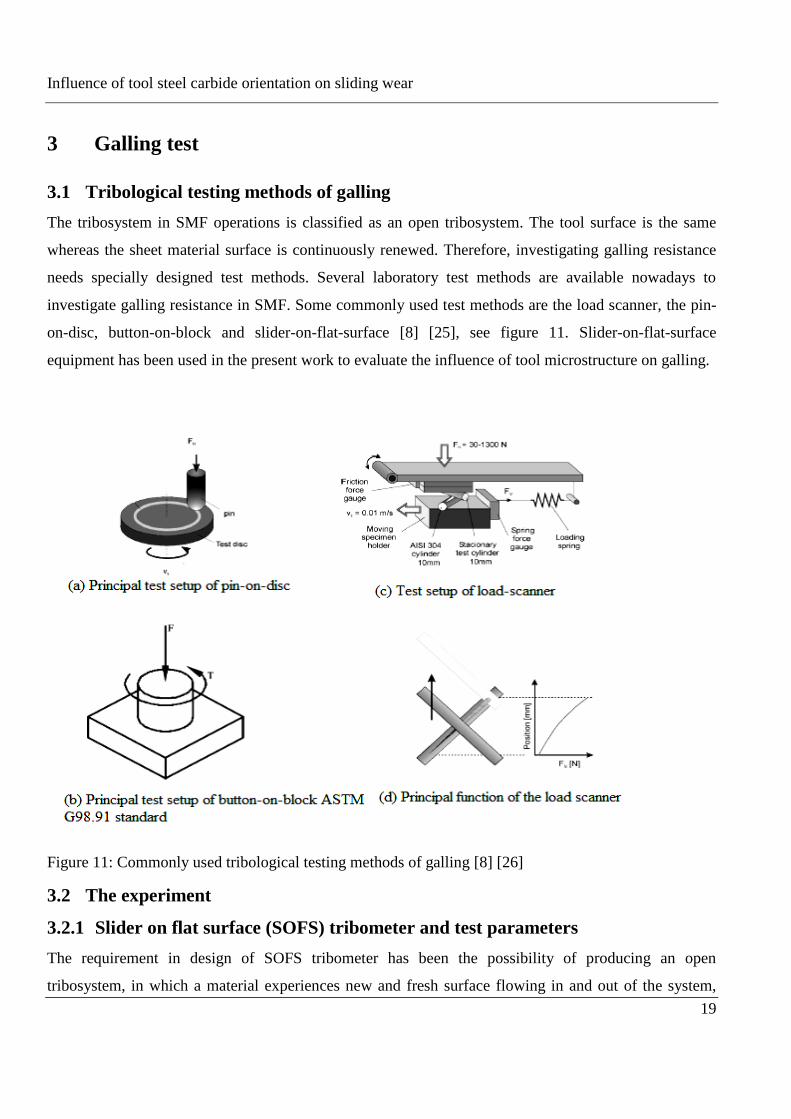
on-disc, button-on-block and slider-on-flat-surface [8] [25], see figure 11. Slider-on-flat-surface
equipment has been used in the present work to evaluate the influence of tool microstructure on galling.
Figure 11: Commonly used tribological testing methods of galling [8] [26]
3.2 The experiment
3.2.1 Slider on flat surface (SOFS) tribometer and test parameters
The requirement in design of SOFS tribometer has been the possibility of producing an open
tribosystem, in which a material experiences new and fresh surface flowing in and out of the system,
Influence of tool steel carbide orientation on sliding wear
20
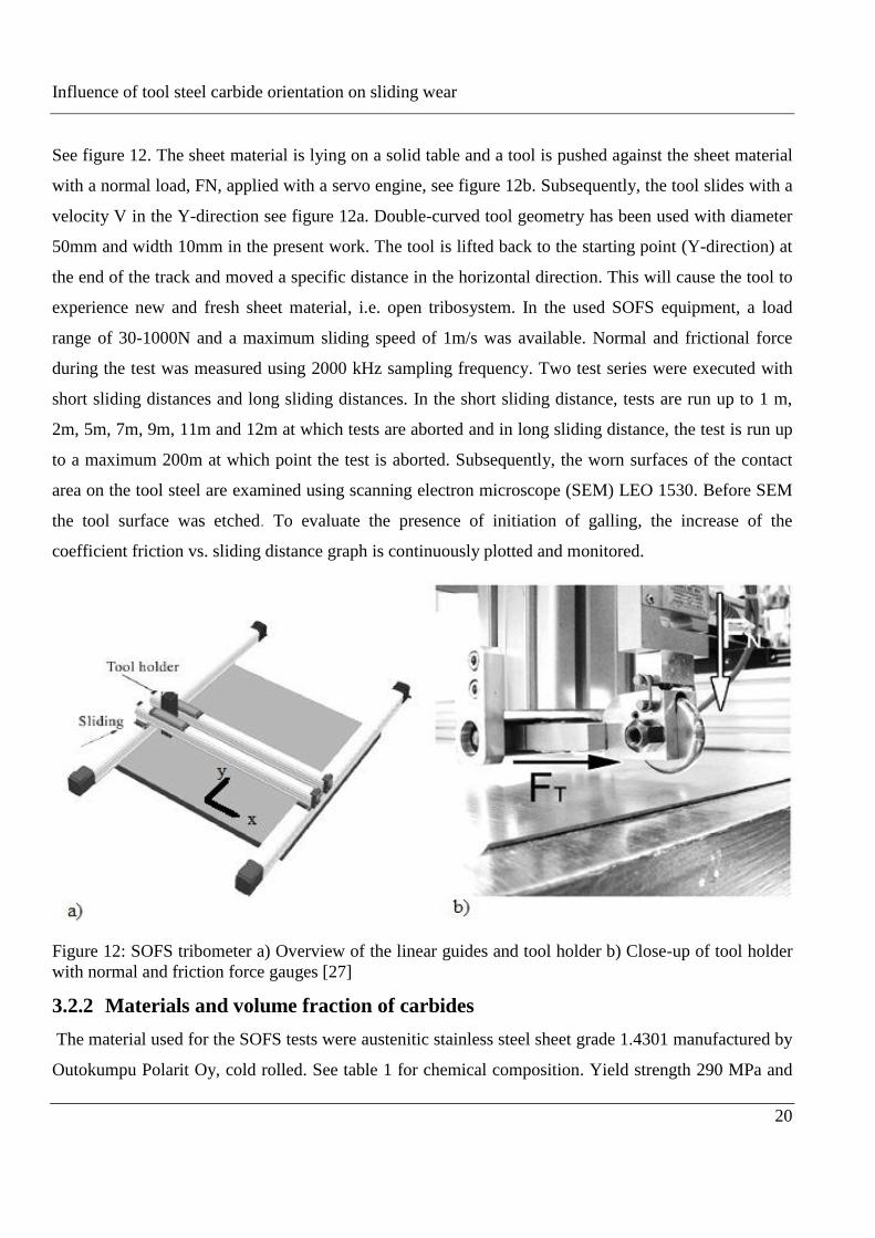
See figure 12. The sheet material is lying on a solid table and a tool is pushed against the sheet material
with a normal load, FN, applied with a servo engine, see figure 12b. Subsequently, the tool slides with a
velocity V in the Y-direction see figure 12a. Double-curved tool geometry has been used with diameter
50mm and width 10mm in the present work. The tool is lifted back to the starting point (Y-direction) at
the end of the track and moved a specific distance in the horizontal direction. This will cause the tool to
experience new and fresh sheet material, i.e. open tribosystem. In the used SOFS equipment, a load
range of 30-1000N and a maximum sliding speed of 1m/s was available. Normal and frictional force
during the test was measured using 2000 kHz sampling frequency. Two test series were executed with
short sliding distances and long sliding distances. In the short sliding distance, tests are run up to 1 m,
2m, 5m, 7m, 9m, 11m and 12m at which tests are aborted and in long sliding distance, the test is run up
to a maximum 200m at which point the test is aborted. Subsequently, the worn surfaces of the contact
area on the tool steel are examined using scanning electron microscope (SEM) LEO 1530. Before SEM
the tool surface was etched. To evaluate the presence of initiation of galling, the increase of the
coefficient friction vs. sliding distance graph is continuously plotted and monitored.
Figure 12: SOFS tribometer a) Overview of the linear guides and tool holder b) Close-up of tool holder
with normal and friction force gauges [27]
3.2.2 Materials and volume fraction of carbides
The material used for the SOFS tests were austenitic stainless steel sheet grade 1.4301 manufactured by
Outokumpu Polarit Oy, cold rolled. See table 1 for chemical composition. Yield strength 290 MPa and
Influence of tool steel carbide orientation on sliding wear
21
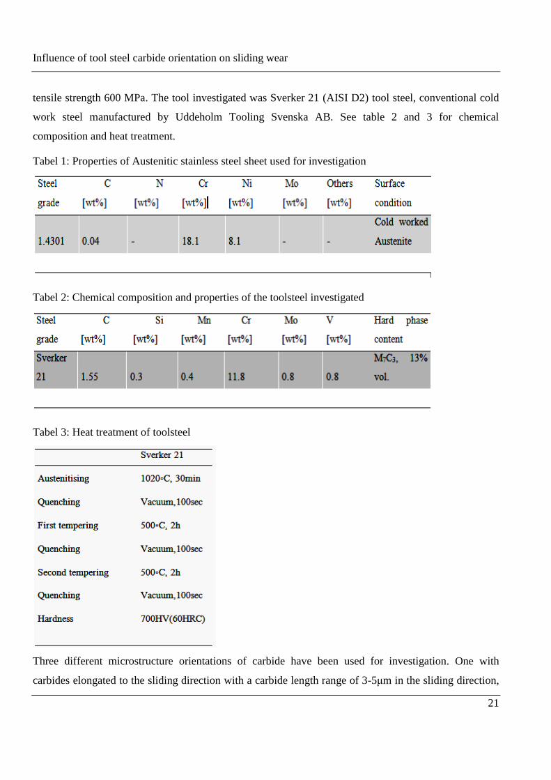
tensile strength 600 MPa. The tool investigated was Sverker 21 (AISI D2) tool steel, conventional cold
work steel manufactured by Uddeholm Tooling Svenska AB. See table 2 and 3 for chemical
composition and heat treatment.
Tabel 1: Properties of Austenitic stainless steel sheet used for investigation
Tabel 2: Chemical composition and properties of the toolsteel investigated
Tabel 3: Heat treatment of toolsteel
Three different microstructure orientations of carbide have been used for investigation. One with
carbides elongated to the sliding direction with a carbide length range of 3-5μm in the sliding direction,
Influence of tool steel carbide orientation on sliding wear
22
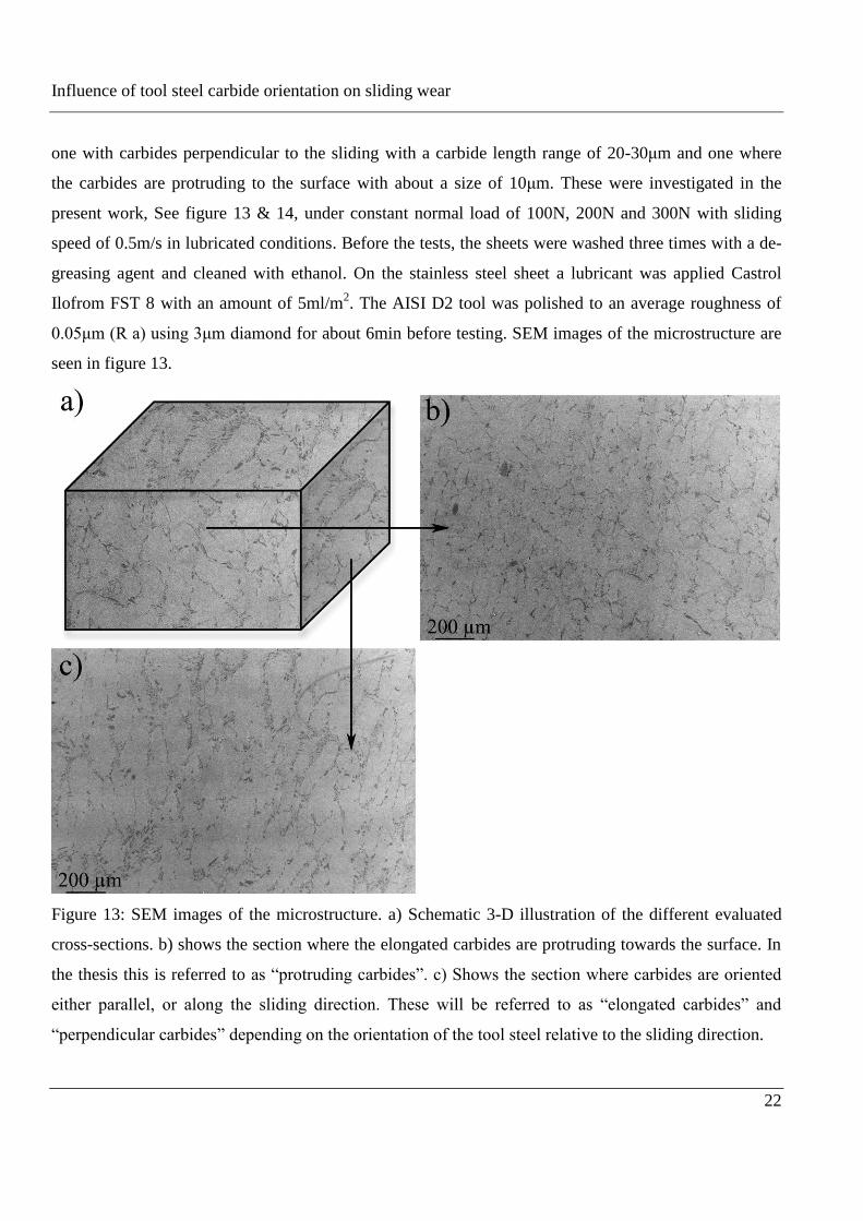
one with carbides perpendicular to the sliding with a carbide length range of 20-30μm and one where
the carbides are protruding to the surface with about a size of 10μm. These were investigated in the
present work, See figure 13 & 14, under constant normal load of 100N, 200N and 300N with sliding
speed of 0.5m/s in lubricated conditions. Before the tests, the sheets were washed three times with a de-
greasing agent and cleaned with ethanol. On the stainless steel sheet a lubricant was applied Castrol
Ilofrom FST 8 with an amount of 5ml/m2. The AISI D2 tool was polished to an average roughness of
0.05μm (R a) using 3μm diamond for about 6min before testing. SEM images of the microstructure are
seen in figure 13.
Figure 13: SEM images of the microstructure. a) Schematic 3-D illustration of the different evaluated
cross-sections. b) shows the section where the elongated carbides are protruding towards the surface. In
the thesis this is referred to as “protruding carbides”. c) Shows the section where carbides are oriented
either parallel, or along the sliding direction. These will be referred to as “elongated carbides” and
“perpendicular carbides” depending on the orientation of the tool steel relative to the sliding direction.
Influence of tool steel carbide orientation on sliding wear
23
Leica Qwin program was used to calculate volume fraction of carbide in the tool steel using SEM image
of the tool surface. To characterize the microstructure in respect to the distribution of carbide and metal
matrix, it was preferable to use SEM image that has magnification of x 300-500 for all investigated tool
microstructure orientation. SEM images of all investigated tools, with same magnification, were
evaluated by automatic software to calculate the area fraction of carbides phase through differences in
reflectivity and/or color.
Influence of tool steel carbide orientation on sliding wear
24
4 Results
4.1 Friction and galling criteria
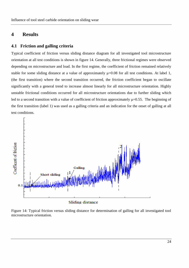
Typical coefficient of friction versus sliding distance diagram for all investigated tool microstructure
orientation at all test conditions is shown in figure 14. Generally, three frictional regimes were observed
depending on microstructure and load. In the first regime, the coefficient of friction remained relatively
stable for some sliding distance at a value of approximately μ=0.08 for all test conditions. At label 1,
(the first transition) where the second transition occurred, the friction coefficient began to oscillate
significantly with a general trend to increase almost linearly for all microstructure orientation. Highly
unstable frictional conditions occurred for all microstructure orientations due to further sliding which
led to a second transition with a value of coefficient of friction approximately μ=0.55. The beginning of
the first transition (label 1) was used as a galling criteria and an indication for the onset of galling at all
test conditions.
Figure 14: Typical friction versus sliding distance for determination of galling for all investigated tool
microstructure orientation.
Influence of tool steel carbide orientation on sliding wear
25
4.1.1 Short sliding test
Short sliding distance was correspondence to the region where the coefficient of friction was stable at a
value of approximately μ= 0.08 for all microstructure orientations and no sign of wear was observed in
term of changes in friction.
4.1.1.1 Wear Mechanisms at short sliding distance
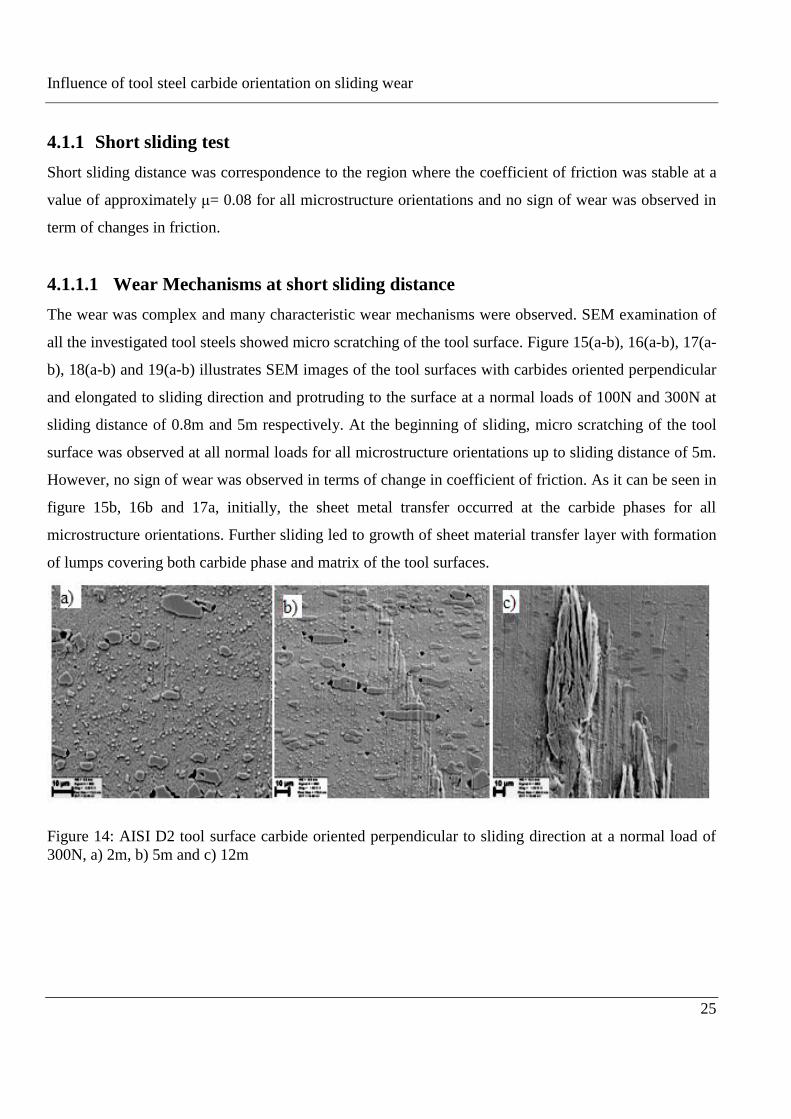
The wear was complex and many characteristic wear mechanisms were observed. SEM examination of
all the investigated tool steels showed micro scratching of the tool surface. Figure 15(a-b), 16(a-b), 17(a-
b), 18(a-b) and 19(a-b) illustrates SEM images of the tool surfaces with carbides oriented perpendicular
and elongated to sliding direction and protruding to the surface at a normal loads of 100N and 300N at
sliding distance of 0.8m and 5m respectively. At the beginning of sliding, micro scratching of the tool
surface was observed at all normal loads for all microstructure orientations up to sliding distance of 5m.
However, no sign of wear was observed in terms of change in coefficient of friction. As it can be seen in
figure 15b, 16b and 17a, initially, the sheet metal transfer occurred at the carbide phases for all
microstructure orientations. Further sliding led to growth of sheet material transfer layer with formation
of lumps covering both carbide phase and matrix of the tool surfaces.
Figure 14: AISI D2 tool surface carbide oriented perpendicular to sliding direction at a normal load of
300N, a) 2m, b) 5m and c) 12m
Influence of tool steel carbide orientation on sliding wear
26
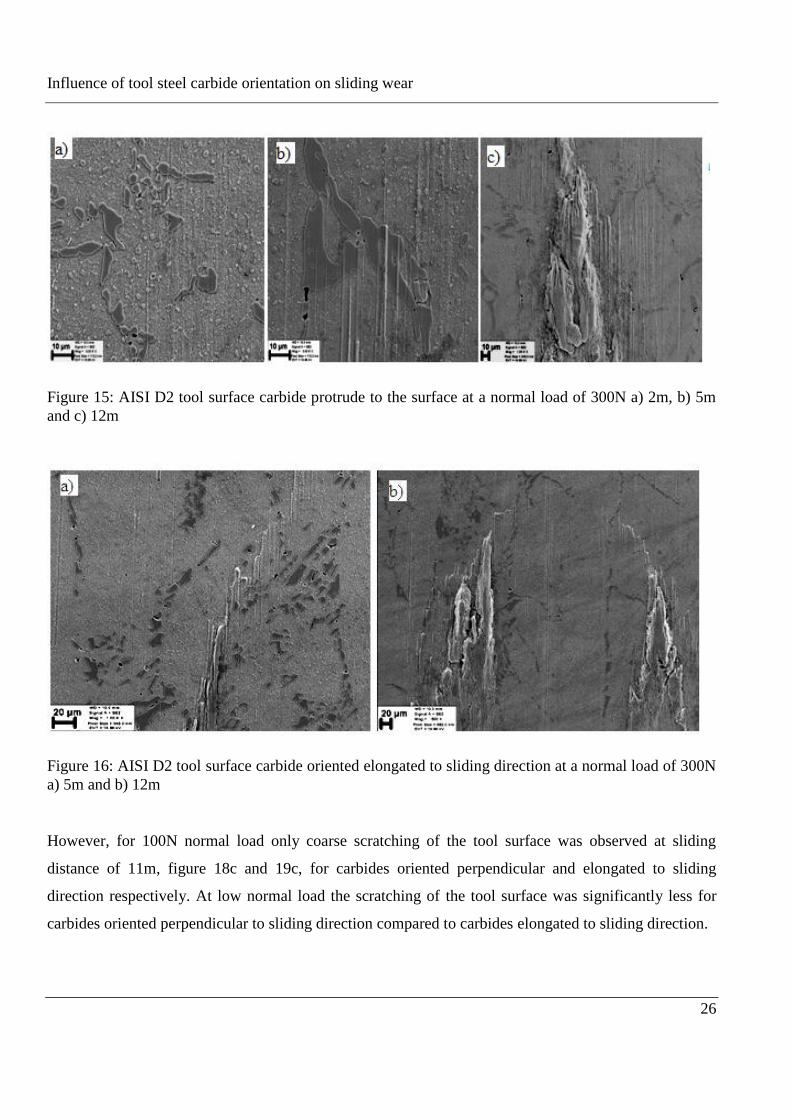
Figure 15: AISI D2 tool surface carbide protrude to the surface at a normal load of 300N a) 2m, b) 5m
and c) 12m
Figure 16: AISI D2 tool surface carbide oriented elongated to sliding direction at a normal load of 300N
a) 5m and b) 12m
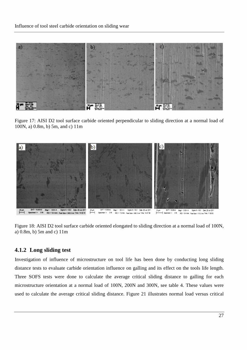
However, for 100N normal load only coarse scratching of the tool surface was observed at sliding
distance of 11m, figure 18c and 19c, for carbides oriented perpendicular and elongated to sliding
direction respectively. At low normal load the scratching of the tool surface was significantly less for
carbides oriented perpendicular to sliding direction compared to carbides elongated to sliding direction.
Influence of tool steel carbide orientation on sliding wear
27
Figure 17: AISI D2 tool surface carbide oriented perpendicular to sliding direction at a normal load of
100N, a) 0.8m, b) 5m, and c) 11m
Figure 18: AISI D2 tool surface carbide oriented elongated to sliding direction at a normal load of 100N,
a) 0.8m, b) 5m and c) 11m
4.1.2 Long sliding test
Investigation of influence of microstructure on tool life has been done by conducting long sliding
distance tests to evaluate carbide orientation influence on galling and its effect on the tools life length.
Three SOFS tests were done to calculate the average critical sliding distance to galling for each
microstructure orientation at a normal load of 100N, 200N and 300N, see table 4. These values were
used to calculate the average critical sliding distance. Figure 21 illustrates normal load versus critical
Influence of tool steel carbide orientation on sliding wear
28
sliding distance. Each point where the lines are connected corresponds to average values from the three
SOFS tests.
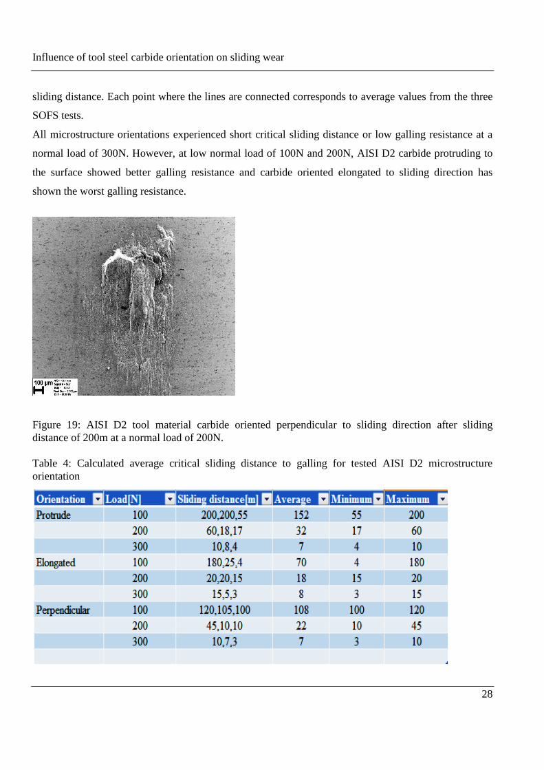
All microstructure orientations experienced short critical sliding distance or low galling resistance at a
normal load of 300N. However, at low normal load of 100N and 200N, AISI D2 carbide protruding to
the surface showed better galling resistance and carbide oriented elongated to sliding direction has
shown the worst galling resistance.
Figure 19: AISI D2 tool material carbide oriented perpendicular to sliding direction after sliding
distance of 200m at a normal load of 200N.
Table 4: Calculated average critical sliding distance to galling for tested AISI D2 microstructure
orientation
Influence of tool steel carbide orientation on sliding wear
29
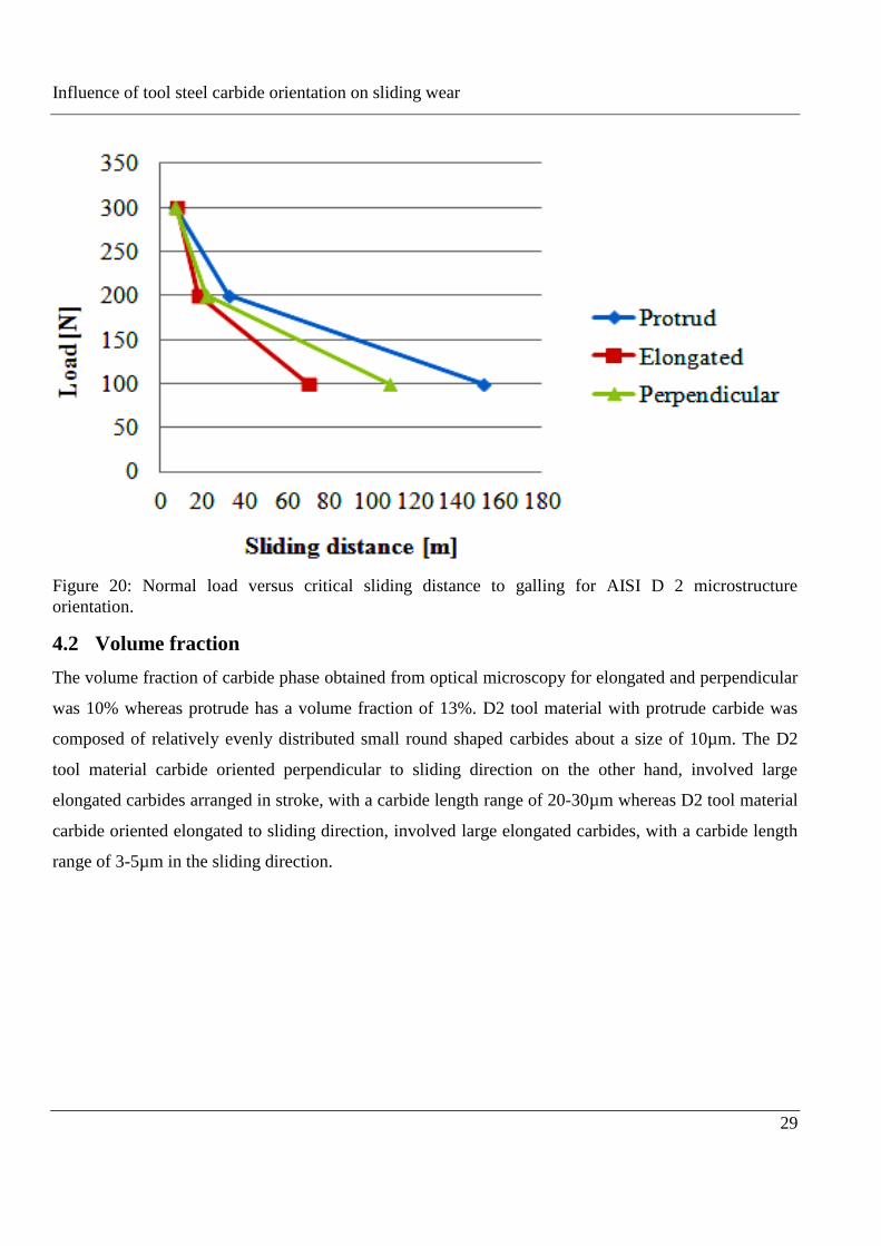
Figure 20: Normal load versus critical sliding distance to galling for AISI D 2 microstructure
orientation.
4.2 Volume fraction
The volume fraction of carbide phase obtained from optical microscopy for elongated and perpendicular
was 10% whereas protrude has a volume fraction of 13%. D2 tool material with protrude carbide was
composed of relatively evenly distributed small round shaped carbides about a size of 10µm. The D2
tool material carbide oriented perpendicular to sliding direction on the other hand, involved large
elongated carbides arranged in stroke, with a carbide length range of 20-30µm whereas D2 tool material
carbide oriented elongated to sliding direction, involved large elongated carbides, with a carbide length
range of 3-5µm in the sliding direction.
Influence of tool steel carbide orientation on sliding wear
30
5 Discussion
In the present work, to evaluate critical sliding distance to galling and wear mechanisms of AISI D2 tool
steel carbide oriented perpendicular, elongated to sliding direction and protruding to the surface, two
SOFS test were conducted, corresponding to short and long sliding distance. The wear process was
complex as the results illustrate. An increase of the coefficient of friction was used as an indication of
the critical sliding distance to galling. That means at the beginning of the first transition (label 1) which
were related to friction rise due to coarse scratching of the sheet, figure 14. Depending on the tool
material carbide orientation and load, the critical sliding distance to galling varied. At the initial stage of
sliding, the wear mechanism was scratching of the tool surface however, as sliding distance increases
sheet material transfer was started at the edge of the carbide phases for all tool microstructure
orientations. This may indicate that the abrasive scratching due to protruding carbides was the
mechanism of the initial sheet material transfer to the tool surface. Nevertheless, the amount of transfer
material on the carbide phase was insignificant as compared to the metal matrix. This is possibly due to
low adhesion of the sheet material to the carbides phase. It may be assumed that since the main
constituent of martensite is iron, the matrix is prone to adhesion. The oxide layer covering asperities of
metal can be destroyed by applying sufficient load and this could allow metal-to-metal contact. Strong
adhesive bonds may form over a large area. This happens at high stress and poor lubrication conditions
[11]. Further sliding led to growth of sheet material transfer with formation of lumps covering both
carbide phase and metal matrix of the tool surfaces. The amount of transferred material was found to be
almost the same for all tool microstructure at a normal load of 300N figure 15c, 16c and 17b. At highest
load the performances of all tool carbide orientations were relatively similar. At normal load of 100N,
carbide oriented elongated to sliding direction have shown micro scratches and some defects compared
to carbide perpendicular to the sliding direction as observed on figure 19c. At low normal load it was
difficult to determine if the carbides were the cause of the wear of the sheet material. As seen in figure
21 both abrasive scratching and adhesive wear mechanism were involved.
AISI D2 steel with round carbide orientation has shown the longest critical sliding distance at low
normal load (100N) and at 200N. This is probably due to a relatively evenly distributed small round
shaped carbides about a size of 10µm. Hence, any substantial growth of the sheet transfer layer involved
interaction with the carbide phase whereas D2 tool steel carbide oriented elongated to sliding direction
has shown the shortest critical sliding distance to galling at a normal load of 100N. The microstructure
of carbide oriented elongated to sliding direction, involved large elongated carbides, with a carbide
Influence of tool steel carbide orientation on sliding wear
31
length range of 3-5µm in the sliding direction. Hence, a relatively small exposer of carbide in the sliding
direction led to wear of a small amount of sheet material, nevertheless, higher exposer of metal matrix.
It may imply that the reason for higher sheet material transfer as compared to carbide oriented
perpendicular to sliding direction, which has a large elongated carbides arranged in stroke, with a
carbide length range of 20-30µm. Hence, a significant exposer of long carbide led to wear of a large
amount of sheet material however low adhesion of the sheet material to the carbide. Therefore,
microstructural orientation and distribution of the carbide phase of the tool material influences the
initiation of galling and tool life length. According to [11] [29] [30] initiation site for galling proposed
to be tool surface defects due to grinding, polishing or scratching produced during testing and tool
damage, for example as in figure 19c, should be avoided.
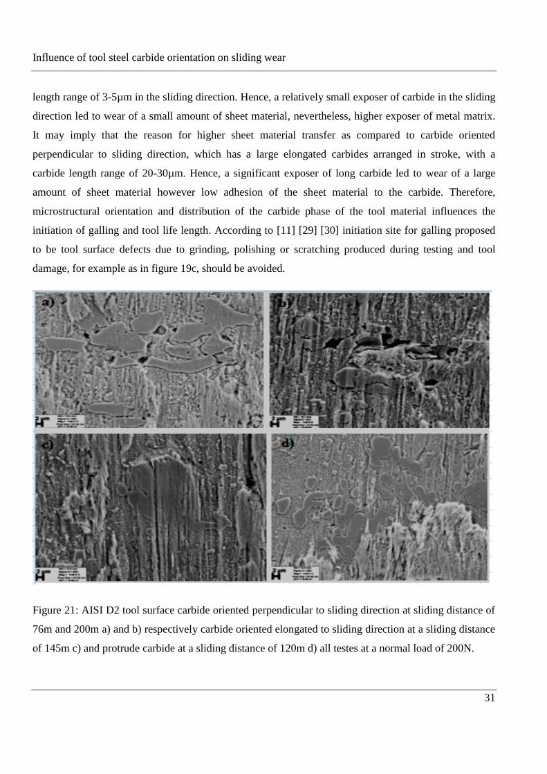
Figure 21: AISI D2 tool surface carbide oriented perpendicular to sliding direction at sliding distance of
76m and 200m a) and b) respectively carbide oriented elongated to sliding direction at a sliding distance
of 145m c) and protrude carbide at a sliding distance of 120m d) all testes at a normal load of 200N.
Influence of tool steel carbide orientation on sliding wear
32
By comparison, of volume fraction of carbide phase in each investigated tool material orientation, there
was no a significant difference between elongated and perpendicular to sliding direction. However, for
tool material with protrude carbide may imply that higher volume fraction of carbide had a positive
influence in terms of galling due to low adhesion of sheet material and possibly relatively reduces
abrasive scratching as compared to carbide elongated and perpendicular to sliding direction.
This trend was in agreement with the critical sliding distance to galling tests, figure 14, where a similar
ranking was obtained, figure 20. This thesis indicates that abrasive scratching due to protruding carbides
at initial stage was an influencing mechanism of the sheet material transfer to the tool surface for all tool
carbide orientation investigated. However scratching of tool surface was not important for tool life
length where as the orientation of the carbide phase and distribution were important for tool life length.
Since there is a lack of research done, further research is necessary on the subject of orientation of
carbide phases in tool material with same chemical composition and its influence on material behavior
during sliding wear.
Influence of tool steel carbide orientation on sliding wear
33
6 Conclusion
In this thesis influence of tool microstructure on initiation of galling for AISI D2 tool steel have been
investigated by using SOFS tribometer. In particular, the influence of microstructure with different
carbide orientation in lubricated sliding against austenitic stainless steel sheet.
The main findings from this work are as follows:
1. Abrasive scratching of the sheet surface by protruding carbides was one cause of the initial wear
of the sheet material. However carbide orientation and distribution were more important for tool
life length.
2. Best tool performance at low normal load was observed for tool with protrude carbide, while the
shortest critical sliding distance to galling was observed for carbide elongated to sliding direction.
The better performance of tool microstructure with protrude carbide was discussed related to
evenly distributed small round shaped carbides and higher volume fraction of carbide had a
positive influence in terms of galling due to low adhesion of sheet material and relatively reduces
abrasive scratching as compared to carbide elongated and perpendicular to sliding direction.

Influence of tool steel carbide orientation on sliding wear
34
Bibliography
1- A. Gåård, P. Krakhmalev, J. Bergström and N. Hallbäck, Galling resistance and wear
mechanisms: Cold work tool materials sliding against carbon steel sheets, Karlstad University,
Sweden, Tribology Letter 26 (2006) 67–72.
2- A. Gåård, P. Krakhmalev, J. Bergström, Influence of tool steel microstructure on orign of galling
initiation and wear mechanisums under dry sliding against a carbon steel sheet, Karlstad
University, Sweden, Wear 267 (2009) 387–393.
3- E.van der Heide, D. J. Schipper, Galling initiation due to frictional heating, University of Twente,
Enschede, The Netherlands, Wear 254 (2003) 1127-1133.
4- A. Gåård, wear in SMF, Karlstad University, Sweden, 2008.
5- Rudi ter Haar, Friction in SMF, the influence of (local) contact conditions and deformation,
Thesis, University of Twente, Enschede, The Netherlands.
6- Per Carlsson, Surface engineering in SMF, Uppsala University, Sweden, 2005.
7- André Westeneng, Modeling of contact and friction in deep drawing, university of Twente,
Enschede, 2001.
8- Magnus Hanson, On adhesion and galling in metal forming, Uppsala University, 2008
9- Outokumpu, Austenitic stainless steel product information, Finland, 2009
10- Outokumpu, Steel Grades, Properties and Global Standards, Finland, 2009
11- Emile van der Heide, Lubricant failure in SMF processes, University of Twente, Enschede, The
Netherlands, 2002.
12- MartensiticStainlessSteels,[electronic].Available:
http://www.keytometals.com/page.aspx?ID=CheckArticle&site=kts&NM=199.
13- Outokumpu, Duplex Stainless steel brochre, Finland, 2010
14- L. Bourithis, G.D. Papadimitriou, J. Sideris, Comparison of wear properties of tool steels AISI
D2 and O1 with the same hardness, National Technical University of Athens, Greece, Tribology
International 39 (2006) 479–489
15- Mats Randelius, Influence of microstructure on fatigue and ductility properties, Royal Institute of
Technology, Sweden, 2008
16- Uddeholm[electronic].available:http://www.uddeholm.com/b_2265.htm, Sweden,2012-05-04
Influence of tool steel carbide orientation on sliding wear
35
17- Uddeholm[electronic].available:http://www.uddeholm.com/Productfinder.htm, Sweden,2012-05-
04
18- D. Rai, B. Singh, J. Singh, Characterization of wear behavior of different microstructures in Ni-
Cr-Mo-V steel, Research & Development Center for Iron and Steel, Steel Authority of India
Limited, India, Wear 263 (2007) 821–829.
19- I. M. Hutchings, Tribology: Friction and wear of engineering materials, University of
Cambridge, London, 1992
20- D. D. Olsson, N. Bay (1), J. L. Andreasen, Prediction of limits of lubrication in strip reduction
testing, Technical university of Denmark, Lyngby, Denmark, 2008
21- E.van der heide ,A.J.Huis in ‘t Veld, D.J.Schipper, The effect of lubricant selection on galling in a
model wear test, The Netherlands, Wear 251 (2001) 973-979.
22- A. Gåård, P. Krakhmalev, J. Bergström, Wear mechanisms in deep drawing of carbon steel-
correlation to laboratory testing, Karlstad University, Sweden, Tribotest Letter 14 (2008) 1–9.
23- Fredrik w. Lindvall, Development of test method for measuring galling resistance Karlstad
University, Sweden, 2007, pp, 19–21.
24- ASTM Standard G98-91, ASTMWest Conshohocken, PA, USA, 1991.
25- B. Podgomik, S. Hogmark, J. Pezdimik, Comparison between different test methods for
evaluation of galling properties of surface engineered tool surface, University of Ljubljana,
Slovenia, Uppsala university ,Sweden, Wear 257 (2004) 843–851.
26- Fredrik w. Lindvall, Development of test method for measuring galling resistance Karlstad
University, Sweden, 2007, pp, 24.
27- F.Lindvall, J. Bergström, P. Krakhmalev, Tool steel and contact geometry influence on galling
initiation in lubricated sliding on carbon steel sheets, Karlstad University, Sweden.
28- I. Heikkilä, Influence of tool steel microstructure on galling resistance against stainless steel,
Swedish Institute for metals Research, Stockholm, Sweden, Proceedings of the 30th Leeds-Lyon
Symposium on Tribology, Transient Processes in Tribology 43 (2003) 641–649.
29- E. Schedin, B. Lehtinen, Galling mechanisms in lubricated system: A study of SMF, Stockholm,
Sweden, Wear 170 (1993) 119–130.
30- Patrik Karlsson, Anders Gåård, Pavel Krakhmalev, Jens Bergström , Galling resistance and wear
mechanisms for cold-work tool steels in lubricated sliding against high strength stainless steel
sheets, Karlstad University, Sweden, Wear 286-287 (2012) 92–97.