influences of fine-particle bombarding and conventional ... · influences of fine-particle...
TRANSCRIPT

Influences of Fine-Particle Bombarding and Conventional Shot Peeningon Surface Properties of Steel
Tatsuro Morita1,+, Sho Noda2 and Chuji Kagaya3
1Department of Mechanical and System Engineering, Graduate School of Science and Technology,Kyoto Institute of Technology, Kyoto 606-8585, Japan2Tokyo Office, Mitsubishi Electric Building Techno-Service Co., Ltd., Tokyo 116-0002, Japan3Department of Mechanical Engineering, Faculty of Engineering, Chubu University, Kasugai 487-8501, Japan
This study was conducted to investigate the influences of fine-particle bombarding (FPB, maximum diameter of collision particles: 34 µm)and conventional shot peening (510µm) on the surface properties of steel. The influence of injection pressure in FPB was also examined. Themicrostructures near surfaces were nano-crystallized by FPB and shot peening. Grain size of nano-crystals was more markedly decreased by FPBthan shot peening, and further reduced by the use of high injection pressure in FPB. Surface hardness increased as the grain size of nano-crystalsdecreased. The hardened layers of the FPBed materials became thicker by the use of high injection pressure; however, they were still shallowerthan the hardened layers of the shot-peened materials. Compressive residual stress measured on surfaces was higher in FPBed materials than inshot-peened materials. The use of high injection pressure in FPB was not effective to further increase this stress.[doi:10.2320/matertrans.M2013322]
(Received August 23, 2013; Accepted January 9, 2014; Published February 21, 2014)
Keywords: fine-particle bombarding, shot peening, injection pressure, hardness of substrates, mild steel, microstructure, nano-crystals, surfacehardness, hardness distribution, residual stress
1. Introduction
Fine-particle bombarding (FPB) is a surface modificationmethod in which fine particles bombard the surface ofmetals.1) In recent years, this method has been widely usedfor various engineering applications because of its markedeffects. In its fundamental principle, FPB is similar toconventional shot peening. The difference between them is inthe size of collision particles: namely, the particle size of FPB(maximum diameter 5 200µm) is much smaller than that ofshot peening (usually = 500µm).
Particle size controls the depth of plastic deformation andapplied energy density per unit volume.2) In the case of FPB,since the kinetic energy of one particle is low, the plastic-deformed region is very shallow; however, numerous fineparticles repeatedly collide at the same positions. As a result,applied energy density becomes markedly higher in FPB thanin shot peening. Marked effects of FPB result from the abovehigh energy density.
Wear resistance and fatigue strength of metals are closelyrelated with surface properties, such as the surface hardness,residual stress and surface roughness. FPB significantlyincreases the surface hardness through nano-crystallizationof the microstructure,36) and introduces high compressiveresidual stress2) without marked deterioration of surfaceroughness. Therefore, FPB greatly improves wear resistance7)
and fatigue strength.2,810)
According to our studies, the combination of plasmatreatments with FPB is more effective to improve the fatiguestrength of titanium than single treatments.1115) FPB canprovide desirable functionality, such as high corrosionresistance by surface alloying.16,17)
Although many results concerning FPB have beenaccumulated as mentioned above, more fundamental data
are required for progression. Our previous study examinedthe influence of substrate hardness on the properties of thesurface layers formed by FPB.18) This study was conductedfurther to investigate the influences of FPB and conventionalshot peening on surface properties of steel. The influence ofinjection pressure in FPB was also examined.
As substrates, two materials with different hardness wereprepared from mild steel. The surface properties of the FPBedand shot-peened materials, such as microstructures, surfacehardness, hardness distribution and residual stress, weresystematically examined. In particular, surface microstruc-tures were observed by transmission electron microscopy(TEM) in detail. Plastic deformation near surfaces wasinvestigated on cross sections by electron backscatterdiffraction (EBSD) analysis.
2. Materials and Experimental Procedures
Table 1 shows the chemical composition of mild steel JISS45C used in this study. The material was the same as thatused in the previous study.18) It was supplied as round barswith a diameter of 12mm.
The material was machined to button-shaped specimens(diameter: 12mm, thickness: 10mm) and fully annealed toeliminate the process history. The specimens were quenchedand tempered at 473K and 873K to change hardness(Table 2). The test sections of specimens were polishedwith emery papers and alumina powders to mirror surfaces.Hereafter, these substrates are called “T473 material” and“T873 material”, respectively.
Table 1 Chemical composition of mild steel JIS S45C used in this study(mass%).
C Si Mn P S Cu Ni Cr
0.44 0.20 0.70 0.022 0.014 0.11 0.072 0.166+Corresponding author, E-mail: [email protected]
Materials Transactions, Vol. 55, No. 4 (2014) pp. 646 to 652©2014 The Japan Institute of Metals and Materials

For reference, their microstructures, mechanical propertiesand hardness are shown in Fig. 1 and Table 3. The micro-structures of the T473 and T873 materials were differentconcerning precipitated carbides (¾-carbide and sphericalcarbide) because the tempering temperature was different.
In this study, FPB and shot peening were conducted underthe conditions labeled “FPB-H” and “SP” in Table 2, whichmean FPB under high injection pressure (0.75MPa) andshot-peening, respectively. In Table 2, the condition of FPBexamined in the previous study was labeled “FPB”. Theresults of the previous study were used for direct comparisonwith the results obtained in this study.
Surface features of the treated surfaces were observed.Microstructures near surfaces were observed on cross sectionspolished to mirror surfaces and etched by 1% Nital etchant(mixture of nitric acid and ethanol). These observations wereperformed by scanning electron microscopy (SEM).
To investigate the surface microstructures in detail, TEMobservation and electron diffraction were conducted in the
direction normal to the treated surfaces. Samples with adiameter of 3mm were cut from the treated surfaces. Toavoid damage, the samples were carefully polished fromthe substrate side, and then ion-milled. Grain size of thesurface microstructures was obtained from the results of TEMobservation.
Surface hardness was measured by a micro-Vickershardness tester under test force of 490mN (50 gf ) and dwelltime of 15 s. Five appropriate square indentations wereselected and the mean values of hardness were used as data.Hardness distributions were obtained on polished crosssections under the test condition mentioned above. In thistest, hardness was measured at each depth five times and theaverages were used as data.
Plastic deformation near surfaces was examined on crosssections by EBSD analysis. As data, inverse pole figure (IPF)maps were obtained under the minimum confidence index(CI) of 0.1.
X-ray residual stress measurement was performed on thetreated surfaces. The measurement conditions were asfollows: X-ray: Cr K¡, diffraction plane: (211), diffractionangle: 2ª = 156.4 deg., ¼ angles: ¼ = 10, 20, 30, 35, 40 deg.(sin2¼ method), oscillation: +/¹3 deg., peak search: full-width at half-maximum method, stress constant: K =¹317.9MPa/deg.
3. Results and Discussion
3.1 Surface features and microstructuresFigure 2 shows the surface features of the FPBed and shot-
peened materials. This figure includes the microstructuresobserved on cross sections.
As shown in Fig. 2, craters were formed on the surfaces bythe collision of particles. The size of craters was increased bythe use of high injection pressure in FPB (T473/FPB-H,T873/FPB-H). It was still smaller than that by shot peening(T473/SP, T873/SP). If compared under the same treatmentconditions, craters became larger by decreasing the hardnessof the substrates.
Distinguishable surface layers, shown by dotted lines inFig. 2, were observed on the cross sections of the FPBedmaterials (T473/FPB-H, T473/FPB, T873/FPB-H, andT873/FPB). As explained in section 3.3, the microstructuresof the surface layers were nano-crystallized. Some studieshave reported that such distinguishable surface layers were
Table 2 Conditions of the heat treatments, FPB and shot peening.
Annealing Quenching Tempering
FPB and shot peening
Maximum diameterof particles,
d/µm
Injection pressure,p/MPa
Material ofparticles
Treatment time,t/s
T473/FPB-H
1083K,3.6 ks,F.C.
1118K,300 s,Q.
473K,3.6 ks,A.C.
34 (#400) 0.75
High-speed steel(about 1000Hv)
10
T473/FPB* 34 (#400) 0.5
T473/SP 510 (#30) 0.5
T873/FPB-H 873K,3.6 ks,A.C.
34 (#400) 0.75
T873/FPB* 34 (#400) 0.5
T873/SP 510 (#30) 0.5
F.C.: furnace-cooled, Q.: quenched, A.C.: air-cooled, *Previous study.18)
T473 T873
10 μm
10 μm
Low
mag
nifi
catio
nH
igh
mag
nifi
catio
n
Fig. 1 Microstructures of the substrates.
Table 3 Mechanical properties and hardness of the substrates.
Young’smodulus,E/GPa
Yieldstrength,·Y/MPa
Tensilestrength,·TS/MPa
Elongation(%)
Reductionin area(%)
HardnessHI/Hv
T473 209 1707 2025 12.0 33.6 606
T873 210 746 832 18.7 60.1 296
Influences of Fine-Particle Bombarding and Conventional Shot Peening on Surface Properties of Steel 647
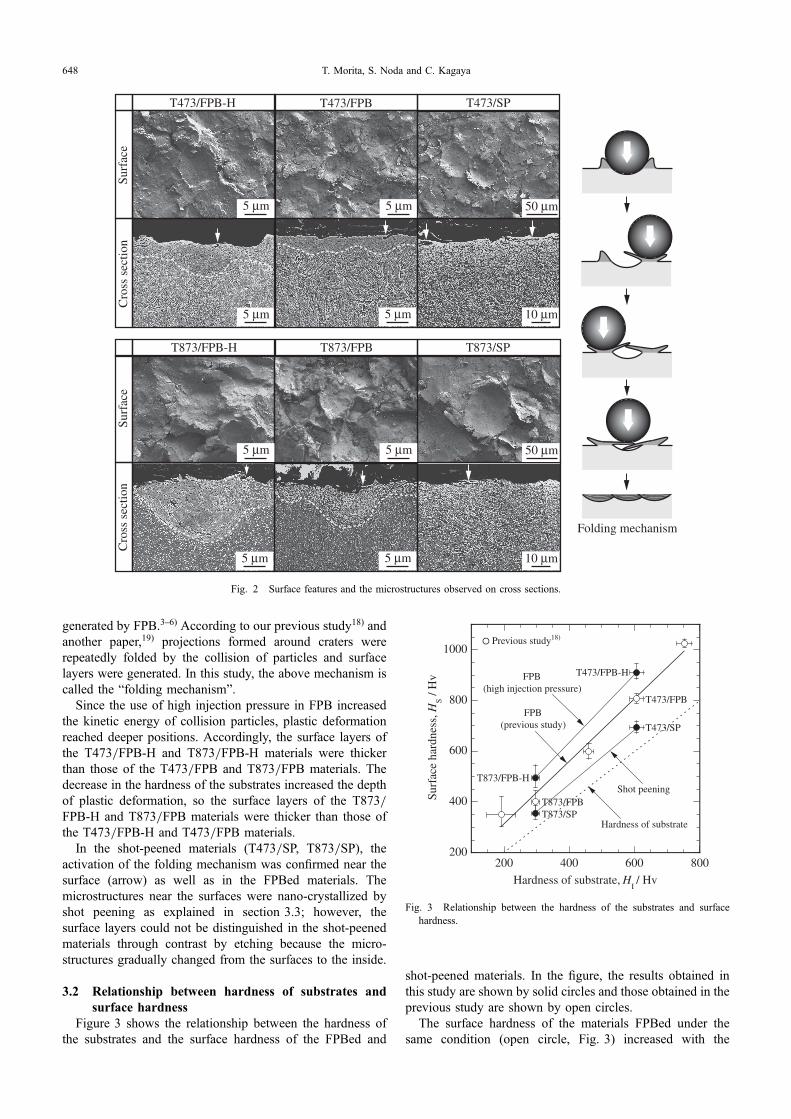
generated by FPB.36) According to our previous study18) andanother paper,19) projections formed around craters wererepeatedly folded by the collision of particles and surfacelayers were generated. In this study, the above mechanism iscalled the “folding mechanism”.
Since the use of high injection pressure in FPB increasedthe kinetic energy of collision particles, plastic deformationreached deeper positions. Accordingly, the surface layers ofthe T473/FPB-H and T873/FPB-H materials were thickerthan those of the T473/FPB and T873/FPB materials. Thedecrease in the hardness of the substrates increased the depthof plastic deformation, so the surface layers of the T873/FPB-H and T873/FPB materials were thicker than those ofthe T473/FPB-H and T473/FPB materials.
In the shot-peened materials (T473/SP, T873/SP), theactivation of the folding mechanism was confirmed near thesurface (arrow) as well as in the FPBed materials. Themicrostructures near the surfaces were nano-crystallized byshot peening as explained in section 3.3; however, thesurface layers could not be distinguished in the shot-peenedmaterials through contrast by etching because the micro-structures gradually changed from the surfaces to the inside.
3.2 Relationship between hardness of substrates andsurface hardness
Figure 3 shows the relationship between the hardness ofthe substrates and the surface hardness of the FPBed and
shot-peened materials. In the figure, the results obtained inthis study are shown by solid circles and those obtained in theprevious study are shown by open circles.
The surface hardness of the materials FPBed under thesame condition (open circle, Fig. 3) increased with the
T873/FPB
T473/FPB-H
T873/FPB-H
Surf
ace
Cro
ss s
ectio
n
T473/FPB
Surf
ace
Cro
ss s
ectio
n
T473/SP
T873/SP
Folding mechanism
5 μm 50 μm
10 μm
5 μm
5 μm5 μm
5 μm 50 μm
10 μm
5 μm
5 μm5 μm
Fig. 2 Surface features and the microstructures observed on cross sections.
200
400
600
800
1000
200 400 600 800
Surf
ace
hard
ness
, HS /
Hv
Hardness of substrate, HI / Hv
Hardness of substrate
T873/FPB-H
T873/FPBT873/SP
T473/FPB
T473/FPB-H
Previous study18)
Shot peening
FPB(previous study)
FPB(high injection pressure)
T473/SP
Fig. 3 Relationship between the hardness of the substrates and surfacehardness.
T. Morita, S. Noda and C. Kagaya648

increase in the hardness of the substrates. If the hardness ofthe substrates was the same, surface hardness was increasedby the use of high injection pressure in FPB, as understoodby comparing T473/FPB-H and T473/FPB materials orT873/FPB-H and T873/FPB materials. The surface hardnessof FPBed materials was higher than that of shot-peenedmaterials, as understood by comparing T473/FPB and T473/SP materials or T873/FPB and T873/SP materials.
3.3 Relationship between surface microstructures andsurface hardness
Figure 4 shows the surface microstructures observed inbright and dark fields by TEM, together with the diffractionpatterns obtained in the observed regions. In Fig. 5, theresults of Fig. 3 have been rearranged to show the relation-ship between the grain size of the surface microstructures andsurface hardness.
It is well known that dynamic recrystallization occurs inthe hot working of metals. The recrystallized grain sizedepends on temperature and strain rate, so-called ZenerHollomon parameters, but does not depend on the strain.On the other hand, when metals are cold-worked underconditions of severe plastic deformation, a different type of
dynamic recrystallization is induced.20) This is often called“continuous dynamic recrystallization”. In this type ofdynamic recrystallization, grain size depends on the severityof plastic deformation.
Since FPB induces nano-crystallization of the surfacemicrostructures through continuous dynamic recrystalliza-tion,36) it is expected that the grain size of nano-crystalsdepends on the degree of plastic deformation. Plasticdeformation near the surface becomes severer by thedecrease of collision particle size and increase in injectionpressure. In the case of substrates with high hardness, sincesmaller projections are made around craters and foldedrepeatedly, severe plastic deformation is induced near thesurface.18) Accordingly, plastic deformation near the surfacebecomes severer also by the increase in the hardness of thesubstrates.
The obtained results supported the above expectation, asmentioned below. As seen in Fig. 4, the surface micro-structures were nano-crystallized in all materials, includingthe shot-peened materials (T473/SP, T873/SP) in which nosurface layer was observed. The grain size of nano-crystalswas more markedly decreased by FPB than by shot peening,and further reduced by the use of high injection pressure inFPB. If compared under the same treatment conditions, thegrain size of nano-crystals was decreased with the increase inthe hardness of the substrates.
Some studies concerning nano-crystalline materials havereported that hardness continued to increase with decreasinggrain size even in the region of very small grains of less than100 nm.2124) Corresponding to these studies, the surfacehardness was increased with the reduction in the grain sizeof the surface microstructures, and there was a HallPetchrelationship between them, as shown in Fig. 5.
Although dislocation hardening affects the surface hard-ness, it is difficult to distinguish the influence of dislocationhardening from that of grain refinement; however, Kimurareported that the hardness of severely plastic-deformed metalwas controlled by grain refinement rather than dislocationhardening when the hardness was beyond about 500Hv.22)
Bright field Dark field Diffraction pattern
T47
3/FP
B
100 nm 100 nm
Bright field Dark field Diffraction pattern
T47
3/FP
B-H
T87
3/FP
B-H
100 nm 100 nm
T47
3/SP
T87
3/FP
BT
873/
SP
Fig. 4 Surface microstructures observed by TEM and the diffractionpatterns.
200
400
600
800
1000
0.1 0.15 0.2 0.25 0.3
Surf
ace
hard
ness
, HS /
Hv
Grain size, D -1/2 / nm-1/2
Previous study18)
T473/FPB-H
T473/FPB
T873/SP
T873/FPB-H
T873/FPB
T473/SP
Fig. 5 Relationship between the grain size of the surface microstructuresand surface hardness.
Influences of Fine-Particle Bombarding and Conventional Shot Peening on Surface Properties of Steel 649

In this study, since the hardness of the substrates waschanged by tempering, the characteristics of cementiteparticles can affect the microstructures of the surface layers.Xu has reported that carbides in steel were dissolved bysevere plastic deformation.25) No cementite particles wereobserved in the surface layers by TEM observation.Accordingly, it was thought that cementite particles weredissolved by FPB and shot peening and had no influence.
Other factors such as Coble creep and the distributionof grain size can affect the hardness of nano-crystallinematerials. Coble creep is mass flow due to grain boundarydiffusion. Some previous studies reported that Coble creepdecreases the hardness of nano-crystalline materials at agrain size 5 1030 nm, even at room temperature.23,24) Thedistribution of grain size also affects the hardness of nano-crystalline materials as well as the average grain size.26)
Nevertheless, the results obtained in this study (Fig. 5)showed that surface hardness increased with the decreasinggrain size of nano-crystals. In consequence, it is probablethat grain refinement is the factor most strongly controllingthe surface hardness of FPBed and shot-peened materials.
3.4 IPF maps and hardness distributionsFigure 6 shows the IPF maps obtained on cross sections of
FPBed and shot-peened materials. In this figure, the dottedlines show the outlines of the surfaces. Figure 7 shows theirhardness distributions measured on cross sections togetherwith surface hardness.
Firstly, the relationship between the microstructures andthe hardness distribution is explained based on the resultsconcerning the group of T873 materials (T873/FPB-H,T873/FPB, and T873/SP). In T873/FPB material (Fig. 6),the IPF map of the surface layer was imperfect because thegrain size of the microstructure was very small. The resultsexplained in the previous sections suggested that themicrostructure of the surface layer was almost uniformlynano-crystallized (Figs. 2, 4). Because of the above uniformmicrostructure, the hardness distribution of T873/FPBmaterial was constant near the surface (solid circle in Fig. 7).
In the region beneath the surface layer of T873/FPBmaterial, the microstructure was compressed and refined,so hardness was increased. Since this region was thin, thehardness distribution sharply dropped from the surfacehardness level to the hardness of the substrate in the depthdirection.
In T873/FPB-H material, the grain size of the micro-structure of the surface layer was further decreased by the useof high injection pressure in FPB and the thickness of thelayer was increased, as explained in the previous sections.In the region beneath the surface layer, the compressed andrefined microstructure extended to a deeper position (Fig. 6).As a result, hardness near the surface (solid triangle in Fig. 7)was higher than that of the T873/FPB material, and thehardened layer became thicker.
The microstructure and hardness distribution of the shot-peened material (T873/SP) were markedly different fromFPBed materials. As shown in Fig. 6, the microstructure nearthe surface was nano-crystallized; however, its grain size waslarger than in FPBed materials. The refined microstructuregreatly extended to a much deeper position, and its grain size
gradually increased in the depth direction. The above changein the microstructure was reflected in the hardness distribu-tion (solid square in Fig. 7); that is, while the hardness nearthe surface was lower than in FPBed materials, the hardenedregion reached a much deeper position.
In the group of T473 materials, since the hardness of thesubstrates was higher than in the group of T873 materialsdescribed above, the affected regions were thinner (Fig. 6)and the hardness distributions were located at higherpositions (open circle in Fig. 7); however, the tendencies of
T87
3/FP
BT
473/
FPB
101
111
001
T47
3/FP
B-H
T87
3/FP
B-H
Low magnification High magnification
T87
3/SP
T47
3/SP
5 μm 5 μm
Low magnification High magnification
101
111
001
5 μm 5 μm
Fig. 6 IPF maps obtained near the surfaces on cross sections.
T. Morita, S. Noda and C. Kagaya650

the changes in the microstructures and hardness distributionswere almost the same as in the group of T873 materials.
Dislocation hardening also affects hardness distribution. Itscontribution could not be distinguished from refinement ofthe microstructures in the range of this study, because bothdepend on the degree of plastic deformation induced near thesurface.
3.5 Residual stressFigure 8 shows the relationship between the hardness of
the substrates and residual stress measured on the treatedsurfaces. The figure includes the results of the materialsexamined in this study (solid circle) and the results obtainedin the previous study (open circle).
When particles collide with a metal surface, the plastic-deformed surface region tends to expand, but is effectivelyconstrained by the material volume below it. As a result,compressive residual stress is introduced near the surface.According to this generation mechanism, the absolute valueof compressive residual stress depends on both the degree ofplastic deformation induced near the surface and the hardnessof substrates.
When the hardness of the substrates increased, plasticdeformation was markedly concentrated in the vicinity of thesurface. At the same time, expansion of the plastic-deformedsurface regions was strongly restricted by the substratespossessing higher hardness. Accordingly, if compared underthe same treatment conditions, the absolute value ofcompressive residual stress increased by increasing thehardness of the substrates, as shown in Fig. 8.
The use of high injection pressure in FPB increased thedegree of plastic deformation induced near the surface,as mentioned in previous sections. Although the absolutevalue of compressive residual stress of T873/FPB-H materialwas higher than T873/FPB material (Fig. 8), the value ofT473/FPB-H material was slightly lower than T473/FPBmaterial. In the range of the obtained results, the use of highinjection pressure in FPB was not very effective to increasecompressive residual stress. As the cause, it was thought thatthe surface layers became thicker by the use of high injection
pressure, so that the deformation in the layers was notsufficiently restricted by the substrates.
The region to which plastic deformation reached was muchthicker in shot peening than in FPB because of the differencein the kinetic energy of particles. Accordingly, the plastic-deformed surface regions of shot-peened materials weredifficult to restrict by the substrates. As a result, the absolutevalues of compressive residual stress were much lower inshot-peened materials (T473/SP, T873/SP) than FPBedmaterials (T473/FPB, T873/FPB).
4. Conclusions
The obtained results are summarized as follows. Forreference, an illustration is shown in Fig. 9.(1) The microstructures near the surfaces were nano-
crystallized by FPB and shot peening. Relating to thedegree of plastic deformation induced near the surface,the grain size of the surface microstructures was moremarkedly decreased by FPB than shot peening, andfurther reduced by the use of high injection pressurein FPB.
(2) Surface hardness was closely connected with the grainsize of the surface microstructures, and it increased asthe grain size decreased.
(3) The use of high injection pressure in FPB increased thesurface hardness and thickness of the hardened layers;however, it was not very effective for increasingcompressive residual stress.
(4) The hardened layers of shot-peened materials weremarkedly thicker than those of FPBed materials. Theirsurface hardness and the absolute value of compressiveresidual stress were much lower than those of FPBedmaterials.
(5) If compared under the same treatment conditions, theincrease in the hardness of the substrates resulted in finesurface microstructures, higher surface hardness, thin-ner hardened layers, and higher compressive residualstress.
-1200
-1000
-800
-600
-400
200 400 600 800
Res
idua
l str
ess,
σR /
MPa
Hardness of substrate, HI / Hv
T873/FPB-H
T873/SP
T473/FPBT473/FPB-H
T873/FPB
T473/SP
Previous study18)
Shot peening
FPB(previous study,
high injection pressure)
Fig. 8 Relationship between the hardness of the substrates and residualstress measured on the treated surfaces.
200
400
600
800
1000
0 10 20 30 40
Har
dnes
s, H
/ H
v
Distance from surface, dS / μm
T473/FPB-HT473/FPBT473/SPT873/FPB-HT873/FPBT873/SP
T473 (substrate)
T873 (substrate)
Fig. 7 Hardness distributions from the surfaces to the inside.
Influences of Fine-Particle Bombarding and Conventional Shot Peening on Surface Properties of Steel 651

Acknowledgments
This research was partially supported by the Japan Societyfor the Promotion of Science, Grant-in-Aid for ScientificResearch (C), 20122014, No. 24560098. The authorsgratefully acknowledge the support. The authors sincerelythank Fujikihan Co., Ltd. for FPB and shot peening.
REFERENCES
1) Fujikihan, Co., Ltd.: Japanese Patent No. 1594395.2) T. Morita, H. Nakaguchi, S. Noda and C. Kagaya: Mater. Trans. 53
(2012) 19381945.3) M. Umemoto, Y. Todaka and K. Tsuchiya: Mater. Trans. 44 (2003)
14881493.4) M. Umemoto: Mater. Trans. 44 (2003) 19001911.5) Y. Todaka, M. Umemoto, Y. Watanabe, A. Yamazaki, C. Wang and K.
Tsuchiya: ISIJ Int. 47 (2007) 157162.6) J. L. Liu, M. Umemoto, Y. Todaka and K. Tsuchiya: J. Mater. Sci. 42
(2007) 77167720.7) X. Y. Wang and D. Y. Li: Wear 255 (2003) 836845.8) M. Benedetti, T. Bortolamedi and V. Fontanari: Int. J. Fatigue 26 (2004)
889897.9) M. Nakajima, M. Kamiya, H. Itoga, K. Tokaji and H. Ko: Int. J. Fatigue
28 (2006) 15401546.10) T. Morita, T. Sakata, C. Kagaya and K. Kawasaki: J. Japan Inst. Metals
75 (2011) 532538.11) T. Morita, T. Ohtomo, C. Kagaya, S. Tanaka and N. Tsuji: J. Soc.
Mater. Sci. Japan 56 (2007) 872879.
12) T. Morita, T. Ohtomo, C. Kagaya, N. Tsuji, S. Tanaka and T. Miyasaka:Ti-2007 Science and Technology II, (The Japan Institute of Metals andMaterials, 2007) pp. 16591662.
13) N. Tsuji, S. Tanaka and T. Takasugi: Mater. Sci. Eng. A 499 (2009)482488.
14) T. Morita, N. Uehigashi and C. Kagaya: Mater. Trans. 54 (2013) 2227.
15) T. Morita, N. Uehigashi and C. Kagaya: Mater. Trans. 54 (2013) 17191724.
16) T. Morita, T. Yorino, C. Kagaya and Y. Miyasaka: Trans. Jpn. Soc.Mech. Eng. A 77 (2011) 13311339.
17) T. Morita, A. Sakamoto, C. Kagaya and H. Nakaguchi: Proc. 10th Int.Con. on Shot Peening ICSP10, (2008) pp. 211216.
18) T. Morita, S. Noda and C. Kagaya: Mater. Sci. Eng. A 574 (2013) 197204.
19) S. Takaki, M. Kumagai, Y. Ito, S. Konuma and E. Shimodaira: Testu-to-Hagane 92 (2006) 318326.
20) X. Zhang, H. Wang, J. Narayan and C. C. Koch: Acta Mater. 49 (2001)13191326.
21) P. G. Sanders, C. J. Youngdahl and J. R. Weertman: Mater. Sci. Eng. A234236 (1997) 7782.
22) Y. Kimura, H. Hidaka and S. Takaki: Mater. Trans. 40 (1999) 14911157.
23) R. A. Masumura, P. M. Hazzledine and C. S. Pande: Acta Mater. 46(1998) 45274534.
24) H. Hidaka, T. Tsuchiya and S. Takaki: Scr. Mater. 44 (2001) 15031506.
25) Y. Xu, Z. G. Liu, M. Umemoto and T. Tsuchiya: Metall. Mater. Trans.A 33 (2002) 21952203.
26) T. Morita, R. Mitra and J. R. Weertman: Mater. Trans. 45 (2004) 502508.
Grain size of surface microstructureLarge Small
Surface hardnessLow High
Compressive residual stressLow Even
FPBShot peening
FPB
Highinjection pressure
Normalinjection pressure
Normalinjection pressure
Thickness of hardened layer
Verythick Thin Thick
(Increase of prticle size) (Increase of injection pressure)
Fig. 9 Schematic illustration to explain the influence of the treatment conditions on surface properties.
T. Morita, S. Noda and C. Kagaya652