informatik 3 - mitschriften von klaas ole k¼rtz
TRANSCRIPT
Informatik 3
Mitschrift von www.kuertz.name
Hinweis: Dies ist kein offizielles Script, sondern nur eine private Mitschrift. Die Mitschriftensind teweilse unvollständig, falsch oder inaktuell, da sie aus dem Zeitraum 2001–2005 stammen. Falls jemand einen Fehler entdeckt, so freue ich mich dennoch übereinen kurzen Hinweis per E-Mail – vielen Dank!
Klaas Ole Kürtz ([email protected])
Inhaltsverzeichnis0 Introduction: Tanenbaum’s „Modern Operating Systems
“ 20.1 Two views of an Operating System . . . . . . . . . . . . . . . 20.2 History of Operating Systems . . . . . . . . . . . . . . . . . . 40.3 Peterson’s Mutual Exclusion Algorithm . . . . . . . . . . . 7
1 The Xinu-Approach 81.1 Operating Systems . . . . . . . . . . . . . . . . . . . . . . . . 81.2 Our Approach . . . . . . . . . . . . . . . . . . . . . . . . . . . 81.3 What an Operating System is not . . . . . . . . . . . . . . . . 81.4 An Operating System viewed from the Outside . . . . . . . . . 8
1.4.1 The Xinu Small Machine Environment . . . . . . . . 81.4.2 Xinu Services . . . . . . . . . . . . . . . . . . . . . . 91.4.3 Concurrent Processing . . . . . . . . . . . . . . . . . . 91.4.4 The Distinction between Programs and Processes . . . 91.4.5 Process Exit . . . . . . . . . . . . . . . . . . . . . . . . 101.4.6 Shared Memory . . . . . . . . . . . . . . . . . . . . . . 101.4.7 Synchronization . . . . . . . . . . . . . . . . . . . . . . 101.4.8 Mutual Exclusion . . . . . . . . . . . . . . . . . . . . . 10
1.5 An Operating System viewed from the Inside . . . . . . . . . . 101.6 Summary . . . . . . . . . . . . . . . . . . . . . . . . . . . . . 11
2 Overview of the Machine and its Run-Time Environment 112.1 The Machine . . . . . . . . . . . . . . . . . . . . . . . . . . . 11
2.1.1 Physical Organization of the LSI 11/2 . . . . . . . . . 112.1.2 Logical Organization of the LSI 11/2 . . . . . . . . . . 122.1.3 Registers in the LSI 11/2 . . . . . . . . . . . . . . . . . 122.1.4 Address space . . . . . . . . . . . . . . . . . . . . . . . 122.1.5 Processor Status Word . . . . . . . . . . . . . . . . . . 132.1.6 Vectored Interrupts . . . . . . . . . . . . . . . . . . . . 132.1.7 Exceptional Conditions . . . . . . . . . . . . . . . . . . 142.1.8 Asynchronous Communication . . . . . . . . . . . . . . 142.1.9 LSI 11 Asynchronous Serial Line Hardware . . . . . . . 142.1.10 Addressing a Serial Line Unit . . . . . . . . . . . . . . 142.1.11 Polled vs. Interrupt-Driven I/O . . . . . . . . . . . . . 14
2.2 Disk Storage Organization . . . . . . . . . . . . . . . . . . . . 142.3 The C-Run-Time Environment . . . . . . . . . . . . . . . . . . 14
2.3.1 Conventions for translating procedures in the C-Compiler 152.4 Summary . . . . . . . . . . . . . . . . . . . . . . . . . . . . . 17
i
3 List and Queue Manipulation 173.1 Linked Lists Of Processes . . . . . . . . . . . . . . . . . . . . 173.2 Implementation of the Q-Structure . . . . . . . . . . . . . . . 18
3.2.1 In-Line Q Functions . . . . . . . . . . . . . . . . . . . 183.2.2 FIFO Queue Manipulation . . . . . . . . . . . . . . . . 18
3.3 Priority Queue Manipulation . . . . . . . . . . . . . . . . . . . 183.4 List Initialization . . . . . . . . . . . . . . . . . . . . . . . . . 183.5 Summary . . . . . . . . . . . . . . . . . . . . . . . . . . . . . 18
4 Scheduling and Context Switching 194.1 The Process Table . . . . . . . . . . . . . . . . . . . . . . . . 194.2 Process States . . . . . . . . . . . . . . . . . . . . . . . . . . . 194.3 Selecting a Ready Process . . . . . . . . . . . . . . . . . . . . 194.4 The Null Process . . . . . . . . . . . . . . . . . . . . . . . . . 214.5 Making a Process Ready . . . . . . . . . . . . . . . . . . . . . 224.6 Summary . . . . . . . . . . . . . . . . . . . . . . . . . . . . . 22
5 More Process Management 225.1 Process Suspension and Resumption . . . . . . . . . . . . . . 22
5.1.1 Implementation of Resume . . . . . . . . . . . . . . . . 225.1.2 The Return Values SYSERR and OK . . . . . . . . . . . 23
5.2 System Calls . . . . . . . . . . . . . . . . . . . . . . . . . . . . 235.2.1 Implementation of Suspend . . . . . . . . . . . . . . . 245.2.2 Suspending the current Process . . . . . . . . . . . . . 24
5.3 Process Termination . . . . . . . . . . . . . . . . . . . . . . . 245.4 Kernel Declarations . . . . . . . . . . . . . . . . . . . . . . . . 255.5 Process Creation . . . . . . . . . . . . . . . . . . . . . . . . . 25
6 Process Coordination 256.1 Low-Level Coordination Techniques . . . . . . . . . . . . . . . 266.2 Implementation of High-Level Coordination Primitives . . . . 266.3 Semaphore Creation and Deletion . . . . . . . . . . . . . . . . 26
7 Message Passing 26
8 Memory Management 27
9 Interrupt Processing 279.1 Dispatching Interrupts . . . . . . . . . . . . . . . . . . . . . . 279.2 Input and Output Interrupt Dispatchers . . . . . . . . . . . . 279.3 The Rules for Interrupt Processing . . . . . . . . . . . . . . . 28
ii
10 Real-Time Clock Management 2910.1 The Real-Time Clock Mechanism . . . . . . . . . . . . . . . . 2910.2 Optimization of Clock Interrupt Processing . . . . . . . . . . . 2910.3 The use of the real-time clock . . . . . . . . . . . . . . . . . . 2910.4 Delta List Processing . . . . . . . . . . . . . . . . . . . . . . . 3010.5 Putting a Process to Sleep . . . . . . . . . . . . . . . . . . . . 3010.6 Delays measured in Seconds . . . . . . . . . . . . . . . . . . . 3010.7 Awaking Sleeping Processes . . . . . . . . . . . . . . . . . . . 3010.8 Deferred Clock Processing . . . . . . . . . . . . . . . . . . . . 31
10.8.1 Procedures for Changing to and from Deferred Mode . 3110.9 Clock Interrupt Processing . . . . . . . . . . . . . . . . . . . . 3110.10Clock Initialization . . . . . . . . . . . . . . . . . . . . . . . . 3110.11Summary . . . . . . . . . . . . . . . . . . . . . . . . . . . . . 31
11 Device independent Input and Output 3111.1 Properties of the input and output interface . . . . . . . . . . 3211.2 abstract Operations . . . . . . . . . . . . . . . . . . . . . . . . 3211.3 Binding abstract Operations to Real Devices . . . . . . . . . . 3311.4 Binding I/O calls to Device Drivers at Run-Time . . . . . . . 3311.5 Implementation of high-level I/O-operations . . . . . . . . . . 3411.6 Opening and Closing Devices . . . . . . . . . . . . . . . . . . 3411.7 Null and Error Entries in Device Table . . . . . . . . . . . . . 3411.8 Initialization of the I/O System . . . . . . . . . . . . . . . . . 3411.9 Interrupt vector Initialization . . . . . . . . . . . . . . . . . . 35
12 An Example Device Driver 3512.1 The device type tty . . . . . . . . . . . . . . . . . . . . . . . 3512.2 Upper and Lower Halves of the Device Driver . . . . . . . . . 3512.3 Synchronization of the Upper and Lower Halves . . . . . . . . 3612.4 Control Block and Buffer Declarations . . . . . . . . . . . . . 3612.5 Upper-Half tty Input Routines . . . . . . . . . . . . . . . . . 3612.6 Upper-Half tty Output Routines . . . . . . . . . . . . . . . . 3612.7 Lower-Half tty Driver Routines . . . . . . . . . . . . . . . . . 36
12.7.1 Watermarks and Delayed Signals . . . . . . . . . . . . 3612.7.2 Lower-Half Input Processing . . . . . . . . . . . . . . . 3612.7.3 cooked Mode and cbreak-Mode Processing . . . . . . 37
12.8 tty Control Block Initialization . . . . . . . . . . . . . . . . . 3712.9 Device Driver Control . . . . . . . . . . . . . . . . . . . . . . 3712.10Summary . . . . . . . . . . . . . . . . . . . . . . . . . . . . . 37
iii
13 System Initialization 3713.1 Starting from Scratch . . . . . . . . . . . . . . . . . . . . . . . 3713.2 Booting Xinu . . . . . . . . . . . . . . . . . . . . . . . . . . . 3813.3 System Startup . . . . . . . . . . . . . . . . . . . . . . . . . . 3913.4 Finding the size of Memory . . . . . . . . . . . . . . . . . . . 3913.5 Initializing System Data Structures . . . . . . . . . . . . . . . 3913.6 Transforming the Program into a Process . . . . . . . . . . . . 3913.7 The Map of Low Core . . . . . . . . . . . . . . . . . . . . . . 3913.8 Summary . . . . . . . . . . . . . . . . . . . . . . . . . . . . . 39
17 A Disk Driver 3917.14Summary . . . . . . . . . . . . . . . . . . . . . . . . . . . . . 4017.1 Operations supplied by the Disk Driver . . . . . . . . . . . . . 4017.2 Controller Request and Interface Register Descriptors . . . . . 4117.3 The List of pending Disk Requests . . . . . . . . . . . . . . . 4117.4 Enqueuing Disk Requests . . . . . . . . . . . . . . . . . . . . . 4217.5 Optimizing the Request Queue . . . . . . . . . . . . . . . . . . 4217.6 Starting a Disk Operation . . . . . . . . . . . . . . . . . . . . 4217.7 The upper-half read Routine . . . . . . . . . . . . . . . . . . . 4217.8 Driver Initialization . . . . . . . . . . . . . . . . . . . . . . . . 4217.9 The upper-half output Routine . . . . . . . . . . . . . . . . . 4317.10The upper-half output Routine . . . . . . . . . . . . . . . . . 4317.11The upper-half seek Routine . . . . . . . . . . . . . . . . . . . 4317.12The lower-half of the Disk Driver . . . . . . . . . . . . . . . . 4317.13Flushing Pending Requests . . . . . . . . . . . . . . . . . . . . 43
iv
Organisatorisches• In der zweiten Woche nach Semesterende wird ein fakultatives „Hands-
on“-Praktikum (eine Woche) angeboten.
• relevant für die Note:
– Mittsemester-Test am Dienstag, den 03.12.2002 (ca. 30%)
– Endsemester-Test am Samstag, den 08.02.2003 (ca. 40%)
– Hausaufgaben (ca. 30%)
• Literatur, die als Kopie ausgeteilt wird:
– Kapitel 1 bis 2 aus: Andrew S. Tanenbaum: Modern Opera-ting Systems
– Kapitel 1 bis 13, 17 bis 18 aus: Douglas Comer: OperatingSystem Design - The Xinu Approach
– Abschnitt „Operating Systems“ aus der C.S.Encyclopedia
Dafür bitte 5 e mitbringen.
• Literaturempfehlung: William Stallings: „Operating Systems“ (4th Editi-on) oder auf deutsch „Betriebssysteme“ (4. Auflage, ISBN 3-8273-7030-2)- siehe www.pearson-studium.de
• Accounts: Von der Rechnerbetriebsgruppe kann sich jeder einen indivi-duellen dauerhaften Account bereitstellen lassen:
1. Formular online ausfüllen: www.informatik.uni-kiel.de⇒ Rech-nerbetriebsgruppe ⇒ Anmeldung
2. Paßwort abholen bei Frau Dort, Verwaltungshochhaus Zimmer 807
1
0 Introduction: Tanenbaum’s „Modern Ope-rating Systems “
0.1 Two views of an Operating System• Without software a computer is a useless lump of metal. Computer-
software is divided into:
1. Systems Programs, managing the operation of the computeritself
2. Application Programs, solving the problems of its users
• Most fundamental system program: Operating Systems
– controlling a computer’s resources
– providing the basis upon which application programs can be written
• Modern computer systems consist of ≥ 1 processors, memories, clocks,I/O devices, terminals, disks, network interfaces - writing programscoordinating these resources is extremely difficult! Even restrictingoneself to all details involving disk drives is almost impossible: If everyprogrammer had to write these, writing application programs would beimpossible. Solution: write layers on top of hardware shielding usersfrom that complexity.
• „The most basic commands are READ and WRITE, each of which requires13 parameters, packed into 9 bytes. These parameters specify such itemsas the address of the disk block to be read, the number of sectors pertrack, the recording mode used on the physical medium, the intersectorgap spacing, and what to do with a deleted-data-address-mark. If youdo not understand this mumbo jumbo, do not worry, that is preciselythe point - it is rather esoteric. When the operation is completed, thecontroller chip returns 23 status and error fields packed into 7 bytes.As if this were not enough, the floppy disk programmer must also beconstantly aware of whether the motor is on or off. If the motor is off,it must be turned on (with a long start-up delay) before data can beread or written. The motor cannot be left on too long, however, or thefloppy disk will wear out. The programmer is thus forced to deal withthe trade-off between long start-up delays versus wearing out floppydisks (and losing data on them).“ (from „modern operating systems“ byAndrew S. Tanenbaum, 1.1.1)
2
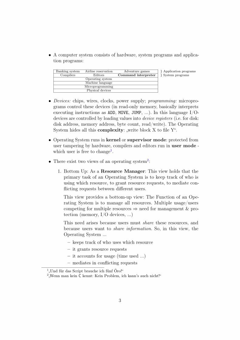
• A computer system consists of hardware, system programs and applica-tion programs:
Banking system Airline reservation Adventure games } Application programsCompilers Editors Command interpreter } System programs
Operating systemMachine languageMicroprogrammingPhysical devices
• Devices: chips, wires, clocks, power supply; programming: micropro-grams control these devices (in read-only memory, basically interpretsexecuting instructions as ADD, MOVE, JUMP, ...). In this language I/O-devices are controlled by loading values into device registers (i.e. for disk:disk address, memory address, byte count, read/write). The OperatingSystem hides all this complexity: „write block X to file Y“.
• Operating System runs in kernel or supervisor mode: protected fromuser tampering by hardware, compilers and editors run in user mode -which user is free to change1.
• There exist two views of an operating system2:
1. Bottom Up: As a Resource Manager: This view holds that theprimary task of an Operating System is to keep track of who isusing which resource, to grant resource requests, to mediate con-flicting requests between different users.
This view provides a bottom-up view: The Function of an Ope-rating System is to manage all resources. Multiple usage/userscompeting for multiple resources ⇒ need for management & pro-tection (memory, I/O devices, ...)
This need arises because users must share these resources, andbecause users want to share information. So, in this view, theOperating System ...
– keeps track of who uses which resource– it grants resource requests– it accounts for usage (time used ...)– mediates in conflicting requests
1„Und für das Script brauche ich fünf Öro!“2„Wenn man kein C kennt: Kein Problem, ich kann’s auch nicht!“
3
2. Top Down: As providing a simple high-level abstraction thathides the truth about horrible hardware from the programmer byproviding a simple interface for a virtual machine (= the realmachine and its system programs)
0.2 History of Operating SystemsThe history of Operating Systems is intimately linked with the history ofcomputers.
0. Charles Babbage’s (1792 - 1871) Analytical Engine (only intheory)
1. 1945 - 1955: based on Vaccum Tubes & Plugboards3
• No separation between builders and users because vacuum tubesbroke down too often (approx. 20.000 of them were used) andprogramming was only possible by wiring plugs up to controlmachine’s basic functions
• The first BUG was found by Grace Murray Hopper on theMark II computer4, is now in the National Museum of AmericanHistory at the Smithonian Institute.
• In the early 1950’s punched cards were used instead of wired-upplugboards.
2. 1955 - 1965: based on Transistors & Batch Systems
• gain in reliability, possibility to sell computers (split betweenbuilders/designers an users/maintenance personnel)
• introduction of high-level machine languages (Cobol, Fortran,Algol, Lisp)
• mode of operation5
• there was a split between:
– word-oriented large scale scientific computers for numericalcalculations
3see Tanenbaum 1.2.14legt Folie vom Logbuch des Mark II mit dem eingeklebten ersten Bug (einer Motte)
auf: „Das wird Euer Leben sein! (...) Das ist Sauron! Sauron kann nicht bekämpft werden,Sauron steht immer wieder auf!“
5see Tanenbaum page 7
4
– character-oriented commercial computers for tape sorting andprinting
3. 1965 - 1980: that of Integrated Circuits, based on IC & Multipro-gramming:
• request for single family satisfying needs of all customers: IBM 360concept: in principle, same program could be run on all computersof the 360 line
• range: from less powerful, decently priced computers to highlyexpensive ones, resulting in a much better price/performance ratio6
• difficulties with programming their Operating System led is 1967to coining the term „software crisis“, everyone’s wave of correctionsin millions of lines of code triggered a new wave of errors ⇒debugging difficult because of lack of structures7
• advantages8:
– multiprogramming to optimize processor usage. Why?∗ with commercial data processing I/O wait time 80 - 90%
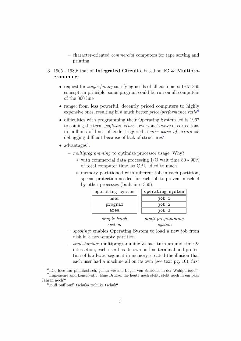
of total computer time, so CPU idled to much∗ memory partitioned with different job in each partition,
special protection needed for each job to prevent mischiefby other processes (built into 360):
operating systemuser
programarea
operating systemjob 1job 2job 3
simple batch multi-programming-system system
– spooling: enables Operating System to load a new job fromdisk in a now-empty partition
– timesharing: multiprogramming & fast turn around time &interaction, each user has its own on-line terminal and protec-tion of hardware segment in memory, created the illusion thateach user had a machine all on its own (see text pg. 10); first
6„Die Idee war phantastisch, genau wie alle Lügen von Schröder in der Wahlperiode!“7„Ingenieure sind konservativ: Eine Brücke, die heute noch steht, steht auch in ein paar
Jahren noch!“8„puff puff puff, tschuka tschuka tschuk“
5
time-sharing system CTSS (1962) implemented on a modifiedIBM 7094
• Multics (MIT, Bell Labs, General Electric): ThisMultiplexed Information and Computing Service should run on onesuch machine and provide computer power for everyone in Boston!⇒ General Electrics stopped producing computers, BellLabs quit project
• Growth of Minicomputers: PDP1-11, VAX, based on LSI (largescale integrated circuits) for single client use; Ken Thomspon,who worked on the Multics-project, found a not used PDP-7minicomputer and wrote a stripped down, single user version ofMultics: Unix!
4. 1980 - now: that of personal computers
• based on vlsi circuits: better price/performance ration
• the micro-processor-chip made it possible for a single individualto have her/his own personal computer: laptop; most powerfulversions: workstations, linked together by a network: distributedcomputing/web
• main-factor for Operating Systems: user friendliness: Thesesystems were intended for users, not knowing anything Fabout computers, and having no intention of learningtheir structure9.
• MS-DOS was dominant on Intel-processors (no protection of hard-ware, virus sensitive) and UNIX was dominant on non-Intel-processorsfor workstations (with hardware protection)
• in a Network Operating System users login on remote machines,copy files from one machine to another; Network Operating Systemconsists of a single processor Operating System & network interfacecontrol & remote login
• Distributed Operating System: composed and running on multipleprocessors, but appears to users as a traditional processor; differentfrom single-processor-systems because of the complex schedulingand problem of communication delays
9„Das erklärt, warum wir in InformatikI 230 Studenten und hier noch 80 Studentenhaben!“
6
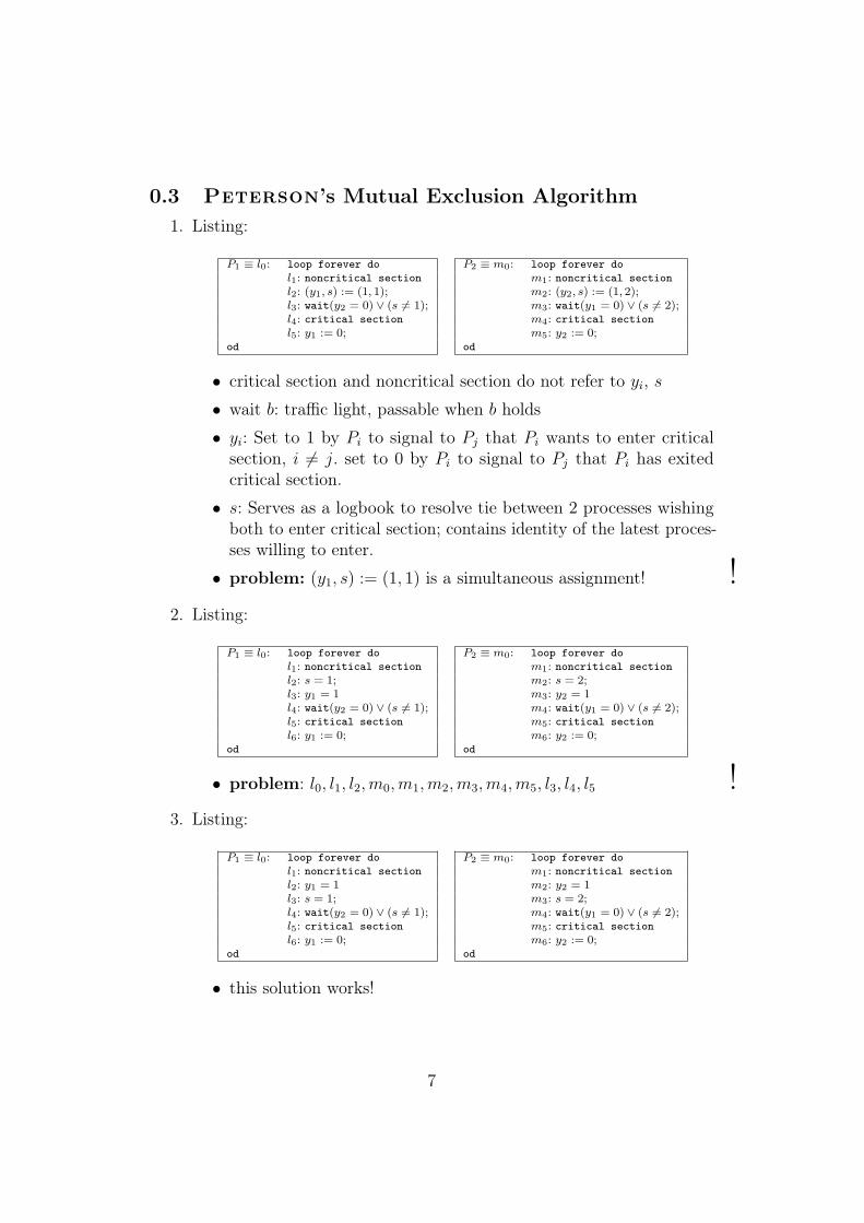
0.3 Peterson’s Mutual Exclusion Algorithm1. Listing:
P1 ≡ l0: loop forever do P2 ≡ m0: loop forever dol1: noncritical section m1: noncritical sectionl2: (y1, s) := (1, 1); m2: (y2, s) := (1, 2);l3: wait(y2 = 0) ∨ (s 6= 1); m3: wait(y1 = 0) ∨ (s 6= 2);l4: critical section m4: critical sectionl5: y1 := 0; m5: y2 := 0;
od od
• critical section and noncritical section do not refer to yi, s
• wait b: traffic light, passable when b holds
• yi: Set to 1 by Pi to signal to Pj that Pi wants to enter criticalsection, i 6= j. set to 0 by Pi to signal to Pj that Pi has exitedcritical section.
• s: Serves as a logbook to resolve tie between 2 processes wishingboth to enter critical section; contains identity of the latest proces-ses willing to enter.
• problem: (y1, s) := (1, 1) is a simultaneous assignment! !2. Listing:
P1 ≡ l0: loop forever do P2 ≡ m0: loop forever dol1: noncritical section m1: noncritical sectionl2: s = 1; m2: s = 2;l3: y1 = 1 m3: y2 = 1l4: wait(y2 = 0) ∨ (s 6= 1); m4: wait(y1 = 0) ∨ (s 6= 2);l5: critical section m5: critical sectionl6: y1 := 0; m6: y2 := 0;
od od
• problem: l0, l1, l2, m0, m1, m2, m3, m4, m5, l3, l4, l5 !3. Listing:
P1 ≡ l0: loop forever do P2 ≡ m0: loop forever dol1: noncritical section m1: noncritical sectionl2: y1 = 1 m2: y2 = 1l3: s = 1; m3: s = 2;l4: wait(y2 = 0) ∨ (s 6= 1); m4: wait(y1 = 0) ∨ (s 6= 2);l5: critical section m5: critical sectionl6: y1 := 0; m6: y2 := 0;
od od
• this solution works!
7
1 The Xinu-Approach
1.1 Operating Systems
1.2 Our ApproachThe Xinu-approach is a practical approach, showing the details of a realsystem; starting with a micro computer and proceeding step-by-step throughthe construction of a layered system.
Advantages: see how an entire system fits together, no mystery about anypart of the implementation, possibility to experiment with the system.
The programs and code form an integral part of the book and the lectures,beginning with a layering scheme and following it consistently.
1.3 What an Operating System is not
1. a language or a compiler: one needs no special language or compilers towrite Operating Systems
2. command interpreter: in modern systems the user can choose its owncommand interpreter
3. library of commands: programs that edit files, send mails, compileprograms ar just utility programs
1.4 An Operating System viewed from the OutsideAn Operating System provides services, programs access these services bymaking system calls. These system calls establish a boundary between therunning program and the Operating System, an Operating System can evenbe described by its services.
With Xinu as illustrating example we explain how to read characters from akeyboard, display characters on a terminal, manage multiple processes andso on.
1.4.1 The Xinu Small Machine Environment
Sometimes computers are too small to compile operating systems. How toget an Operating System on the computer?
• minimum configuration on client
8
• entire system on a larger machine (host)
• user compiles on host with cross-compiler
• downloader copies the memory image to the client (serial connection)
• execution proceeds on the client
Otherwise, one version of the Operating System can be used to create thenext version (Bootstraping).
1.4.2 Xinu Services
1.4.3 Concurrent Processing
Concurrent processing means that many computations proceed „at the sametime“. In contrast, conventional programs are called sequential because theprogrammer imagines a machine executing the code statement-by-statement.
To create the illusion of concurrent processing the Operating System switchesa single processor among multiple programs, the Operating System itself is agood example of a concurrent program. The lowest level of Operating Systemis the scheduler handling all these processes.
1.4.4 The Distinction between Programs and Processes
There a some major differences between programs and processes:
• A procedure call does not return until the called procedure completes.Create and resume return to the caller after starting the process, allowingexecution of both the calling procedure and the named procedure toproceed concurrently.
• A program consist of code executed by a single process. In sharp contrast,processes are not uniquely associated with a piece of code: multipleprocesses can execute the same code simultaneously.
• Storage for local variables and procedure arguments is associated withthe process executing the procedure, not with the code in which theyappear.
Just like a sequential program, each process has its own stack of procedurecalls. Whenever it executes a call, the called procedure is pushed onto thestack; whenever it return from that procedure, it is popped of the stack.
9
1.4.5 Process Exit
The system call kill(P) terminates the process with process-ID P.
To kill a process with name process just call kill(getPID("process")) .
1.4.6 Shared Memory
1.4.7 Synchronization
Look at the consumer/producer-problem: How can the programmer synchro-nize producer and consumer, so that the consumer receives every datumproduced? The mechanism for synchronization of producer and consumermust be designed carefully, because:
• In a single processor system, no process should use the CPU whilewaiting for another process. Xinu avoids busy waiting by supplyingcoordination primitives called semaphores, and system calls wait(s)and signal(s) operating on semaphore s
• wait(s) decrements semaphore s and causes the process to wait if theresult is negative; signal(s) increments s, allowing some waiting processto continue
1.4.8 Mutual Exclusion
Mutual exclusion can be realized with semaphores, it is used to avoid raceconditions - for example in a print spooler. No two processes are in theircritical section at the same time, no process running outside the criticalsection may block other processes.
1.5 An Operating System viewed from the InsideThe layers of Xinu:
1. Hardware
2. Memory Manager
3. Process Manager
4. Process Coordination
5. Interprocess Communication
6. Real-Time Clock Manager
10
7. Device Manger and Device Drivers
8. Intermachine Network Communication
9. File System
10. User Programs
1.6 SummaryThe operating system manages to provide reasonable high-level serviceswith unreasonably low-level hardware, hiding the details of the low-levelmachine. Since 1967 each layer of the operating system provides an abstractservice, implemented in terms of the abstract machine provided by the lower-level layers. User access the operating system by system calls; possibility ofconcurrent programming (a grand illusion!).
The Distinction between Programs and Processes10: A procedure calldoes not return until the called procedure completes. Create and resume11
return to the caller after starting the process, allowing execution of both thecalling procedure and the named procedure to proceed concurrently12.
2 Overview of the Machine and its Run-TimeEnvironment
2.1 The MachineThe Digital Equipment Corporation LSI 11/2 16-bit-microprocessor- a microcomputer version of the PDP11. Discussed here: describing pertinentfeatures of the processor, memory, and communication devices. It explainsthe architecture, asynchronous communication, disk storage devices and me-chanisms like the stack, vectored interrupts and device addressing.
2.1.1 Physical Organization of the LSI 11/2
The LSI 11/2 is constructed from printed circuit boards, slotted into thesockets of a backplane. These sockets are wired together to form a bus (the
10Zu seiner eigenen Folie: „Ich hoffe, daß das lesbar ist - meines Erachtens ist es dasnicht!“
11„resume ist wie ein Ehepaar, es erzeugt ein Kind und setzt sein Leben fort!“12„Frauen können hervorragend nebenläufig denken, das war früher in den Höhlen so!
Concurrent processing findet hauptsächlich statt im Kopf einer Frau!“
11
Q-bus) consisting of power lines (attached to all board in parallel) an lineslinking up the sockets for interboard communication (signals travel to theboard on one contact and away on another). One board contains the 11/2processor itself, other boards contain memory or device interfaces and so on.
A board communicates with another board by passing signals across the bus.E.g., when the processor board needs to write unto memory, it places address& data (16 + 16 Bit) on the bus for the memory board to retrieve & store.
Memory is logically contiguous, each board contains switches (hardwiredjumpers) that can be changed: it is possible to configure two identical memoryboars so that one responds to low memory addresses and the other to highaddresses. The physical order of boards along the Q-bus determines theirpriority (used later).
Signals enter a board on one connector and leave it on another one, so theboard can decide whether to intercept the signal or pass it on downthe bus; example: two boards waiting for service.
2.1.2 Logical Organization of the LSI 11/2
2.1.3 Registers in the LSI 11/2
Register R4 points to calling procedures frame, while R5 points to frame ofcurrently active called procedure.
Notation Register UseR0 0 general purposeR1 1 general purposeR2 2 general purposeR3 3 general purposeR4 4 previous displayR5 5 current displaySP 6 stack pointerPC 7 programm counterPS status processor status
2.1.4 Address space
The memory is divided into 8-bit-quantities called bytes (also called character)being the smallest addressable unit. Most instructions operate on two bytes
12
(a word), they affect addressed byte & the next higher byte. All addresses areformulated in octal ! The LSI 11/2 hat 64K Bytes of Memory (216 bytes)13:
from to use of memory0000000 0000777 for interrupts and exception vectors0001000 0157777 real available memory, the stack grows
in direction from 0157777 to 010000160000 0177777 address space for devices
2.1.5 Processor Status Word
Processor Priority: To disable interrupts set processor/interrupt mask to0111002 = 3408.
15 through 8 7 through 5 4 3 through 0... Processor Priority Trace Mode Condition Codes
2.1.6 Vectored Interrupts
The LSI 11/2 uses the vectored interrupt scheme14 for handling exceptionsand interrupts from external devices. Whenever an external device mustcommunicate with the processor, the device places a signal on the interruptbus line. If the processor runs with interrupts enabled, it checks the interruptline after executing every instruction.
To handle an interrupt, the processor sends an acknowledgement overthe bus, requesting the interrupting device to return an interrupt vectoraddress (IVA). Each device is assigned a unique interrupt vector address,enabling the system software to identify/distinguish among them. The firstdevice with a pending request receives the acknowledgement and respondsby returning its interrupt vector address (an interrupt vector consists of twobytes).
When CPU receives the interrupt vector address v from the Q-bus, theprocessor pushes current value of PC and PS on stack, and loads a newPC and PS from 2 words in memory starting at location v, and continuesexecution beginning at the new location addressed by PC.
The interrupt „acts“ like a procedure call, inserted (invisibly) by the hardwarein between two instructions in the user’s code. The processor executes the
13„Dort schläft schon ein Herr, laßt ihn schlafen, er hat’s verdient, er hat heute Nachtviel Spaß gehabt - hoffen wir!“
14„Das ist nur etwas Blödes, das ist nicht schwer!“
13
code in the interrupt routine and returns to the place where the user’sprogram was interrupted.
2.1.7 Exceptional Conditions
2.1.8 Asynchronous Communication
The serial line unit sends and receives characters asynchronously on threewires (data in two directions and electrical ground). The Transmitter sendsseries of pulses, 8 bit together with optional start, stop and parity bit; theConversion is done by Universal Asynchronous Receiver and Transmitter(UART).
Sender and Receiver have own clocks and try to sample the series of pulses,each bit gets sampled several times, inconsistency results in framing errorand too much characters means character overrun error. A line remainingidle in the wrong state for an extended period gives a break (e.g. needed fordownloading operating system into memory, see (1.4.1)).
2.1.9 LSI 11 Asynchronous Serial Line Hardware
2.1.10 Addressing a Serial Line Unit
The CPU has to read and write to special addresses beyond the realmemory, e.g. 01775608, 01775628, 01775648, 01775668.
2.1.11 Polled vs. Interrupt-Driven I/O
Polling requires the CPU to check the device repeatedly until it finds that acharacter is waiting. To use interrupt-driven processing instead of polling,each subsequent character will cause an interrupt.
2.2 Disk Storage OrganizationWird erst in den letzten zwei Wochen der Vorlesung behandelt!
2.3 The C-Run-Time EnvironmentOperating Systems are written in high-level languages to make them easierto write, understand, debug and move to other machines. However, someti-mes machine assembly language procedures are introduced because machinequantities must be directly manipulated, e.g. for saving and restoring the ma-chine’s registers, writing context-switching code, writing interrupt-handling,
14
implement semaphores and so on. The Storage Layout for a C-Program lookslike:
0 _ etext _ edata _ endtext data bss free space ←− · · · stack
Because the whole Xinu-system is one C-program, the storage layout whenXinu runs is modified:
0 _etext _edata _endtext data bss free space ← stack #3 ← stack #2 ← stack #1
The symbols _etext, _edata and _end refer to global variables inserted intoobject program by the loader, they are initialized to the first address beyondtext, data and bss segments. Thus a running program can find out how muchmemory remains between the end of the loaded part and the current top ofstack by taking the address of _end.
2.3.1 Conventions for translating procedures in the C-Compiler
proc A {some_code_1 ;ca l l B ( arg1 , . . . , argn ) ;some_code_2 ; }
In this example15, A is the calling, B the called procedure. How is the codeof calling procedure B within the procedure body of A in C’s compiler?
1. The values of actual parameters of B (in reverse order) are pushedon the stack.
2. The address of return address in A (i.e. of the instruction following tothe call of B, some actions in picture above) are pushed on the stack.
3. Then the flow of control branches to B.
Calling procedure (A) is also responsible for popping B’s arguments from thestack after the called procedure (B) returns.
• code of calling procedure A:. . . // B ’ s arguments put on stackj s r pc , addB // pushes re turn address on stack
// and branches to subrout ine B. . . // arguments o f B popped from stackr t s pc // pops an address from the stack
// and re tu rn s to that address
15„Mein Gehalt ist so etwa 7 bis 10 e pro Minute, wenn ich vorlese - also nutzt das!“
15
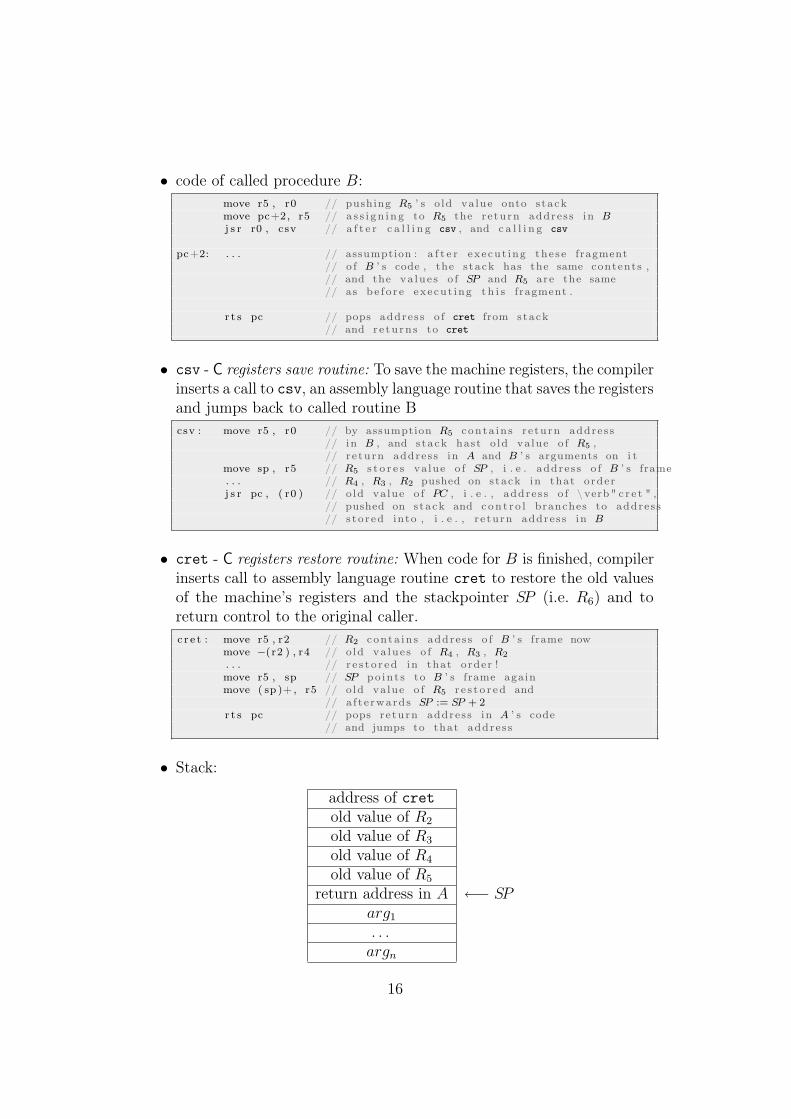
• code of called procedure B:move r5 , r0 // pushing R5 ’ s o ld value onto s tackmove pc+2, r5 // a s s i gn i ng to R5 the re turn address in Bj s r r0 , csv // a f t e r c a l l i n g csv , and c a l l i n g csv
pc+2: . . . // assumption : a f t e r execut ing these fragment// o f B ’ s code , the s tack has the same contents ,// and the va lue s o f SP and R5 are the same// as be f o r e execut ing t h i s fragment .
r t s pc // pops address o f cret from stack// and re tu rn s to cret
• csv - C registers save routine: To save the machine registers, the compilerinserts a call to csv, an assembly language routine that saves the registersand jumps back to called routine Bcsv : move r5 , r0 // by assumption R5 conta in s re turn address
// in B , and stack hast o ld value o f R5 ,// re turn address in A and B ’ s arguments on i t
move sp , r5 // R5 s t o r e s va lue o f SP , i . e . address o f B ’ s frame. . . // R4 , R3 , R2 pushed on stack in that orderj s r pc , ( r0 ) // o ld value o f PC , i . e . , address o f \ verb" c r e t " ,
// pushed on stack and con t r o l branches to address// s to r ed into , i . e . , r e turn address in B
• cret - C registers restore routine: When code for B is finished, compilerinserts call to assembly language routine cret to restore the old valuesof the machine’s registers and the stackpointer SP (i.e. R6) and toreturn control to the original caller.c r e t : move r5 , r2 // R2 conta in s address o f B ’ s frame now
move −(r2 ) , r4 // o ld va lue s o f R4 , R3 , R2
. . . // r e s t o r ed in that order !move r5 , sp // SP po in t s to B ’ s frame againmove ( sp )+ , r5 // o ld value o f R5 r e s t o r ed and
// a f t e rwards SP := SP + 2r t s pc // pops re turn address in A ’ s code
// and jumps to that address
• Stack:
address of cretold value of R2
old value of R3
old value of R4
old value of R5
return address in A ←− SParg1
. . .argn
16
2.4 Summary
3 List and Queue Manipulation
3.1 Linked Lists Of ProcessesList processing is fundamental for operating systems since one needslists of processes to be scheduled (ready for scheduling), processes waitingon a semaphore, processes ordered by priority (time) in order to implementtime-sharing (sleep list).
Two types are needed here: FIFO queues are ordered by time of insertion,priority queues are ordered by time to wake up (in view of time-sharing);necessary operations:
• inserting an item at the tail of a list or within an ordered list
• removing an item at the lead of a list
• allocating a new list
Programming these operations is simple because only one process executesthese operations at a time. This is due to the fact that they occur only incritical sections (programmed by forbidding interrupts16 in the fields of theprocess status register). Elements are extracted from FIFO queue by removingthem from the head, hence they are inserted at its tail.
If the list is a priority queue, getfirst(head) removes the item with thesmallest key, and getlast(tail) removes the item with the biggest key. Hencepriority queue insertion starts at head of the priority queue.
Items to be stored in lists are process identifiers (there are NPROCprocesses) with MININT ≤ process priority ≤ MAXINT . All lists aredoubly linked, i.e. each node points to its successor as well as predecessor, andeach node contains a key; each list has both a head and a tail, predecessorof head and successor of tail point to empty list (= -1); head node containsMININT as key, tailnode MAXINT .
Optimization is possible because a process appears on at most one list at anytime; queue-array has nodes for each process in its [0 . . . NPROC − 1]-part,and head and tail nodes for every list needed in it [NPROC . . .NQENT ]-part.
16„. . . interrüpts . . . “
17
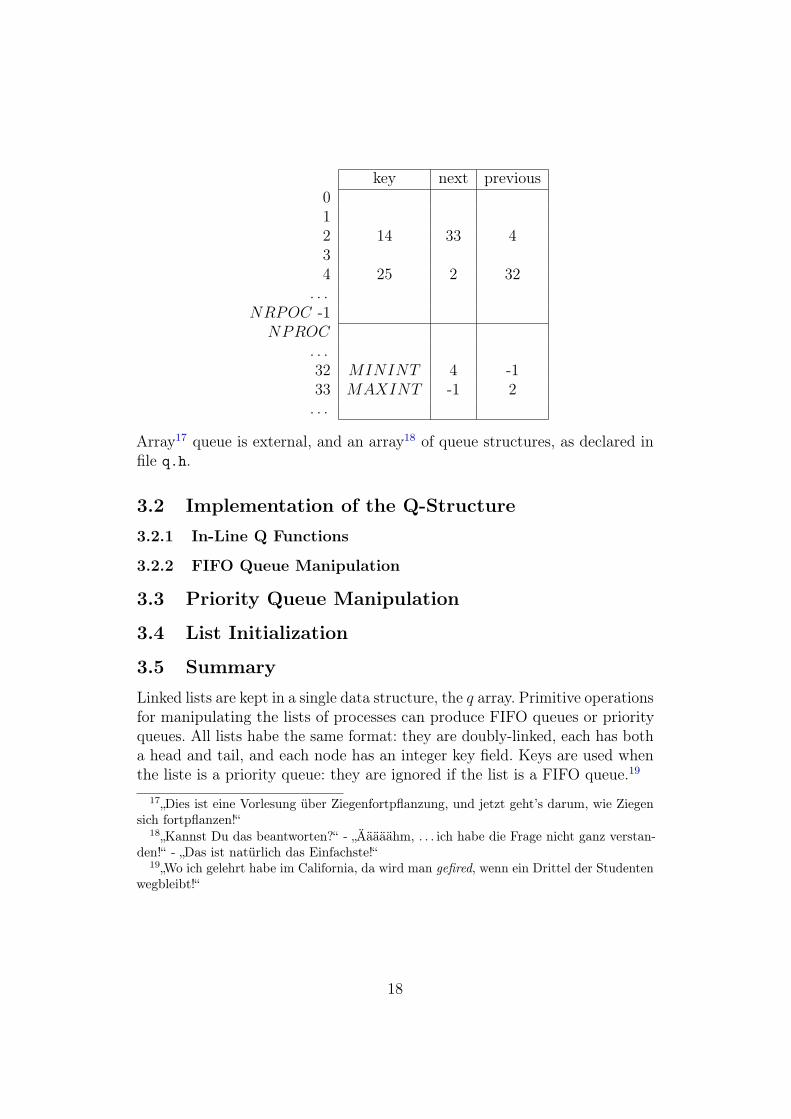
key next previous012 14 33 434 25 2 32
. . .NRPOC -1
NPROC. . .32 MININT 4 -133 MAXINT -1 2. . .
Array17 queue is external, and an array18 of queue structures, as declared infile q.h.
3.2 Implementation of the Q-Structure3.2.1 In-Line Q Functions
3.2.2 FIFO Queue Manipulation
3.3 Priority Queue Manipulation
3.4 List Initialization
3.5 SummaryLinked lists are kept in a single data structure, the q array. Primitive operationsfor manipulating the lists of processes can produce FIFO queues or priorityqueues. All lists habe the same format: they are doubly-linked, each has botha head and tail, and each node has an integer key field. Keys are used whenthe liste is a priority queue: they are ignored if the list is a FIFO queue.19
17„Dies ist eine Vorlesung über Ziegenfortpflanzung, und jetzt geht’s darum, wie Ziegensich fortpflanzen!“
18„Kannst Du das beantworten?“ - „Ääääähm, . . . ich habe die Frage nicht ganz verstan-den!“ - „Das ist natürlich das Einfachste!“
19„Wo ich gelehrt habe im California, da wird man gefired, wenn ein Drittel der Studentenwegbleibt!“
18
4 Scheduling and Context SwitchingWhy is scheduling and context switching difficult? Because the CPU cannotbe stopped at all!
4.1 The Process TableThe proctab is an array of structures pentry, there is one entry for eachprocess in this table. Because only one process running at the time one ofthese entries is out-of-date, since corresponding with the currently activeprocess. The other entries correspond to processes which are temporarilyhalted.
Exactly what info must be saved in proctab? All values that will be destroyedwhen another process runs; e.g. no copy of the stack because there a separatestack areas for different processes. In addition to data that must be reloadedwhen it resumes a process, the system also keeps information in the processtable that it uses to control processes and account for their resources.
Processes are referenced by their process id, which is the index of the savedstate information in proctab.
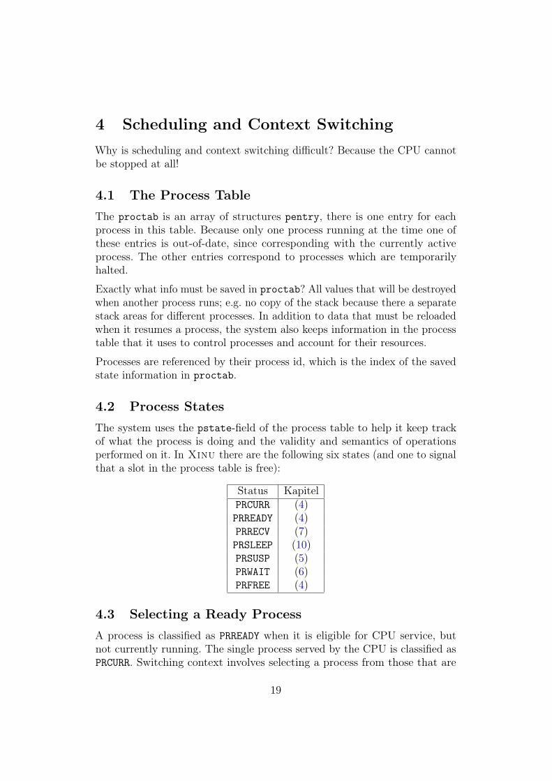
4.2 Process StatesThe system uses the pstate-field of the process table to help it keep trackof what the process is doing and the validity and semantics of operationsperformed on it. In Xinu there are the following six states (and one to signalthat a slot in the process table is free):
Status KapitelPRCURR (4)PRREADY (4)PRRECV (7)PRSLEEP (10)PRSUSP (5)PRWAIT (6)PRFREE (4)
4.3 Selecting a Ready ProcessA process is classified as PRREADY when it is eligible for CPU service, butnot currently running. The single process served by the CPU is classified asPRCURR. Switching context involves selecting a process from those that are
19
ready or current, giving control to the selected process.
Often it remains eligible to use CPU, even when control is temporarily passedto another process (e.g. as a result of round-robin scheduling). Then it’scurrent process state changes to PRREADY and it is moved to ready list forlater CPU service.
How does the Rescheduler (resched) decide whether to move current processto ready list? If current process is not eligible to use the CPU, the systemroutines assign a desired next state to its pstate-field before calling resched.
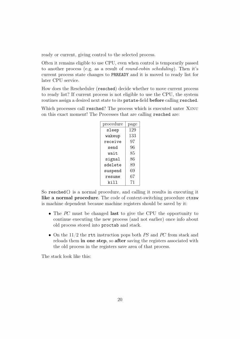
Which processes call resched? The process which is executed unter Xinuon this exact moment! The Processes that are calling resched are:
procedure pagesleep 129wakeup 133receive 97send 96wait 85
signal 86sdelete 89suspend 69resume 67kill 71
So resched() is a normal procedure, and calling it results in executing itlike a normal procedure. The code of context-switching procedure ctxswis machine dependent because machine registers should be saved by it:
• The PC must be changed last to give the CPU the opportunity tocontinue executing the new process (and not earlier) once info aboutold process stored into proctab and stack.
• On the 11/2 the rtt instruction pops both PS and PC from stack andreloads them in one step, so after saving the registers associated withthe old process in the registers save area of that process.
The stack look like this:
20
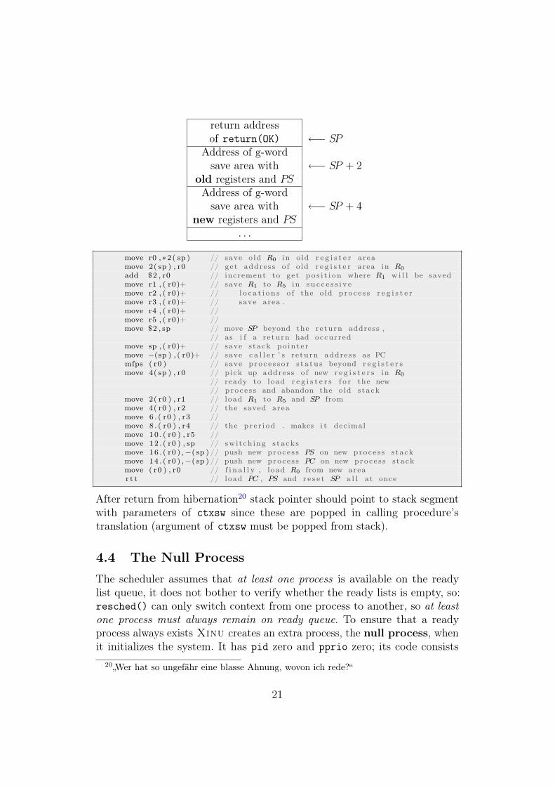
return addressof return(OK) ←− SP
Address of g-wordsave area with ←− SP + 2
old registers and PSAddress of g-wordsave area with ←− SP + 4
new registers and PS. . .
move r0 ,∗2 ( sp ) // save o ld R0 in o ld r e g i s t e r areamove 2( sp ) , r0 // get address o f o ld r e g i s t e r area in R0
add $2 , r0 // increment to get p o s i t i o n where R1 w i l l be savedmove r1 , ( r0)+ // save R1 to R5 in s u c c e s s i v emove r2 , ( r0)+ // l o c a t i o n s o f the o ld proce s s r e g i s t e rmove r3 , ( r0)+ // save area .move r4 , ( r0)+ //move r5 , ( r0)+ //move $2 , sp // move SP beyond the re turn address ,
// as i f a re turn had occurredmove sp , ( r0)+ // save s tack po in t e rmove −(sp ) , ( r0)+ // save c a l l e r ’ s r e turn address as PCmfps ( r0 ) // save p ro c e s s o r s t a tu s beyond r e g i s t e r smove 4( sp ) , r0 // pick up address o f new r e g i s t e r s in R0
// ready to load r e g i s t e r s f o r the new// proce s s and abandon the o ld s tack
move 2( r0 ) , r1 // load R1 to R5 and SP frommove 4( r0 ) , r2 // the saved areamove 6 . ( r0 ) , r3 //move 8 . ( r0 ) , r4 // the p r e r i od . makes i t decimalmove 10 . ( r0 ) , r5 //move 12 . ( r0 ) , sp // swi t ch ing s ta ck smove 16 . ( r0 ) ,−( sp ) // push new proce s s PS on new proce s s s tackmove 14 . ( r0 ) ,−( sp ) // push new proce s s PC on new proce s s s tackmove ( r0 ) , r0 // f i n a l l y , load R0 from new arear t t // load PC , PS and r e s e t SP a l l at once
After return from hibernation20 stack pointer should point to stack segmentwith parameters of ctxsw since these are popped in calling procedure’stranslation (argument of ctxsw must be popped from stack).
4.4 The Null ProcessThe scheduler assumes that at least one process is available on the readylist queue, it does not bother to verify whether the ready lists is empty, so:resched() can only switch context from one process to another, so at leastone process must always remain on ready queue. To ensure that a readyprocess always exists Xinu creates an extra process, the null process, whenit initializes the system. It has pid zero and pprio zero; its code consists
20„Wer hat so ungefähr eine blasse Ahnung, wovon ich rede?“
21
of an infinite loop (see page 196). Because user processes all have prioritygrater than zero, the scheduler switches to the null process only when no userprocess is ready to run.
4.5 Making a Process ReadyMaking a process eligible for CPU service occurs so often that a specialprocedure has been designed to do so: ready(pid, resched). In principleputting a process on the ready lists should result in a call to resched to makesure that the process with the highest priority is running. However, sometimesthis results in a too heavy overhead in execution time when many processesare put on the ready queue (exapmle: process wakeup in realtime interruptprocessing, see page 133). Then all these processes are put on the readylist without rescheduling after each one, only after the last one resched())is called once. This construction is made possible by providing ready(pid,resched) with a boolean argument resched.
4.6 Summary
5 More Process Management
5.1 Process Suspension and ResumptionTransparentes Einfrieren und Entfrosten eines Prozesses: Wie beim Kon-textwechsel zwischen CURRENT und READY: Retten aller potentiell wichtigenDaten, auf Benutzerwunsch Systemaufruf (system call) und Einfrieren „bisauf expliziten Widerruf“ (neuer Zustand SUSPEND)
Jeder Prozess hat jeweils genau einen der (in Xinu 6) möglichen Zustände.Bisher (die fundamentalen für Timesharing/Multiprogramming): CURRENT(laufend) und READY (lauffähig, aber gerade nicht dran); neu: SUSPENDED (d.h.temporäres, benutzergesteuertes Gestopptsein, also nicht gleich READY), esexistiert aber keine SUSPENDED-Queue!
Der suspended-Status wird z.B. benutzt, um pages vom Datenträger zu la-den, die in Benutzerprogrammen referenziert wurden und im Hauptspeichererwartet werden.
5.1.1 Implementation of Resume
Wie bei allen Systemaufrufen, werden am Anfang die Interrupts deaktiviert(disable(ps)) und am Ende wieder aktiviert (enable(ps)). resume setzt
22

den Status eines Prozesses auf READY und setzt ihn entsprechend auf dieready-list.
Resume calls resched, and hence changes the process table and the q-structure.Reason for the need of turning interrupts off when accessing the centraldata structures of Xinu: What happens when another process would besimultaneously changing the process table? This situation is, in general, calledrace condition. The final state of the process table is not clear!
simultaneously{x = 1 | x = 2 | x = 3} ⇒ x =?
To prevent such situations from happening, this uncertainty is prohibited bydisabling interrupts while accessing the process table.
How can resched() be called? By calling sleep/wakeup, receive/send, wait/si-gnal, suspension/resume (see page 128). However this kind of call presupposesthat resched() is called in parallel to the current process. Interleaving theinstructions of this concurrent (parallel) processing in between the instructi-ons of the current process implies that, e.g., the real-time clock procedurehas interrupted the current process. However, this is impossible when thecurrent process is deaf to interrupts. For then the real-time clock interrupt istemporarily postponed.
Question: Does this necessarily imply that the process reacts to interruptsagain? No, the interrupts may have been turned off before calling resched()!
5.1.2 The Return Values SYSERR and OK
Es werden Fehlerbedingungen abgefragt und ggf. wird ein SYSERR ausgegeben.
5.2 System CallsSystemaufrufe sind vom Benutzer aufrufbar, in der Regel sind sie mit beson-deren Privilegien ausgestattet; siehe dazu auch Anhang 2.2. Aufgaben sindzum einen, eine Schnittstelle zwischen Anwenderprogrammen und Systemkernzu bieten, also die Dienste des Betriebssystems bereitzustellen, zum anderen,das System zu schützen.
Grob gesagt: Systemaufrufe sind alles, was der Benutzer vom System verlangt.Klassifizierung:
• Prozeßmanagement und Signale, Interprozesskommunikation
• Filemanagement, Verzeichnis- und Filesystemmanagement
23
• Schutzfunktionen
• Zeitmanagement oder allgemeines Informationsmanagement
• Ein- und Ausgabe (z.B. Öffnen, Schliessen, Terminalattribute, Geschwin-digkeiten, . . . )
• (Speichermanagement)
There is only one process table in the system, shared by all its processes.So how can a process be sure that no other process is trying to change theprocess table at the same time?
1. It should not call resched(), because rescheduling switches control toanother process and this changes the process table
2. The system should not react to interrupts, since interrupt routines cancall resched() as well.
5.2.1 Implementation of Suspend
suspend löscht einen Prozess mit READY-Status von der ready-list bzw. stopptggf. den aktuell ausgeführten Prozess.
5.2.2 Suspending the current Process
Ein Prozess kann sich selbst suspendieren mit suspend(getpid())).
5.3 Process TerminationSuspend freezes processes, but leaves them in the system so they can beresumed later. Another system call, kill21, stops a process immediately andremoves it from the system completely. It checks the pid (so the null processcan’t be killed), decrements the number of processes that currently exists andfrees the stack used by the process. The further action taken by kill dependon the process’ state (handle waiting semaphores, dequeue the process), finallythe process state is set to PRFREE.
21„Wie sagte man früher im Wilden Westen? Der Prozess ist vogelfrei!“
24
5.4 Kernel DeclarationsIn der Datei kernel.h werden zentrale, Betriebssystem-weite Systemkonstan-ten (Beispiele: Abkürzungen für Register, Typen, Standardwerte, . . . ) undRoutinen (Inline-Prozeduren, u.a. asm-Befehle) definiert. Dabei werden dieInline-Funktionen nicht als normale Funktionen deklariert, um damit dasErstellen und Löschen von Stackeinträgen etc. zu sparen, diese Lösung isteffizienter.
5.5 Process CreationEin neuer Prozess wird mit dem Systemaufruf create erschaffen, es erfolgtdie Zuweisung aller benötigten Resourcen und Daten (entsprechend denParametern des Systemaufrufs). Es wird eine neue pid vergeben, es wird derEintrag in der Prozesstabelle angelegt, der Stackbereich wird reservier undVariablen wie Priorität, Name, Anzahl der Argumente werden festgelegt. Derneue Prozess kann nicht sofort CURRENT werden, sondern muß mit resumegestartet werden.
Nicht alle Prozesse werden vom Benutzer einzeln getötet, Problem: wie bereitetman den natrürlichen Tod eines Prozesses vor? Antwort: indem der Prozeßbeim letzten return nicht „irgendwohin“ zurückkehrt, sondern anständigweggeräumt wird. Mit der vorgestellten Lösung werden die C-Konventionenbeachtet, es wird ein Prozeduraufruf simuliert (Pseudocall), dessen initialerStack bereits den Konventionen gehorchen muß und entsprechend gefälschteRücksprungadresse (zu userret())) und Argumente enthält.
Der Code von create ist in drei Phasen gegliedert: Stackbereich reklamieren,Daten u.a. in die Prozesstabelle eintragen und pid zurückgeben.
6 Process CoordinationProzeßkoordinierung ist notwendig um Aktionen von Prozessen zu synchroni-sieren und um den Zugriff auf gemeinsame Ressourcen zu regeln, beispielsweisebeim Producer-Consumer-Problem oder bei Mutual Exclusion. Die einfachsteMöglichkeit zur Prozeßkoordinierung bieten Semaphore.
25
6.1 Low-Level Coordination Techniques
6.2 Implementation of High-Level Coordination Primi-tives
Jede Semaphore s ist im Prinzip ein Integer-Wert. Der Systemaufruf wait(s)reduziert s um 1, signal(s) erhöht s um 1. Wird s beim Aufruf von wait(s)negativ, wird der Prozeß angehalten; beim Aufruf von signal(s) wird einProzeß, der auf s wartet, aufgeweckt. Die Xinu-Implementierung vermeidetbusy waiting durch Einführung eines neuen Prozeßzustandes PRWAIT. Zu jederSemaphore gehört eine eigene Warteschlange.
A nonnegative semaphore count means that the queue is empty, a se-maphore count of negative n means that the queue contains n waitingprocesses.
6.3 Semaphore Creation and Deletion
7 Message PassingInterprozesskommunikation ist ein wichtiges Mittel in Betriebssystemen, z.B.shell-pipeline in Unix (IPC zwischen Benutzerprozessen). Verschiedene Me-chanismen zur Implementierung sind beispielsweise Semaphore zur Koordina-tion/Synchronisation; Monitore; gemeinsame Variablen oder message passing.Anders als Synchronisation durch Semaphore kann message passing unsyn-chronisiert sein; es wird implementiert durch die Systemaufrufe send(...)und receive(...).
Senden und Empfangen können blockierend (beide blockierend: rendez-vouz )oder nicht-blockierend sein; die Kapazität der Verbindung (Pufferlänge) spielteine Rolle (was passiert, wenn der Puffer voll ist?); sollen Nachrichten festeroder variabler Länge gesendet sein; soll es möglich sein, mehrere Prozesse alsEmpfänger anzugeben?
In Xinuexistieren zwei Formen des Nachrichtenaustauschs: 1. direkt vonProzeß zu Prozeß, 2. über Rendevous-Punkte. Dabei sind send und recvclrasynchron, während receive synchron arbeitet. In Xinuexistiert nur einEmpfangspuffer der Länge eins, d.h. nur die erste Nachricht wird übertragen.Zudem wird ein neuer Prozeßzustand PRRECV eingeführt.Das Senden signalisiert einen Fehler, falls Prozeß-ID nicht paßt oder derEmpfangspuffer bereits voll ist. Das Asynchrone Empfangen ist ähnlich demsynchronen Empfangen, falls die Nachricht vorhanden ist: Rückgabe der
26
Nachricht, sonst OK. Beim synchronen Empfangen wird der Prozess ggf. aufden Prozeßzustand PRRECV gesetzt und wartet zunächst, bis er wieder vonsend aufgeweckt wird.
8 Memory Management
9 Interrupt Processing
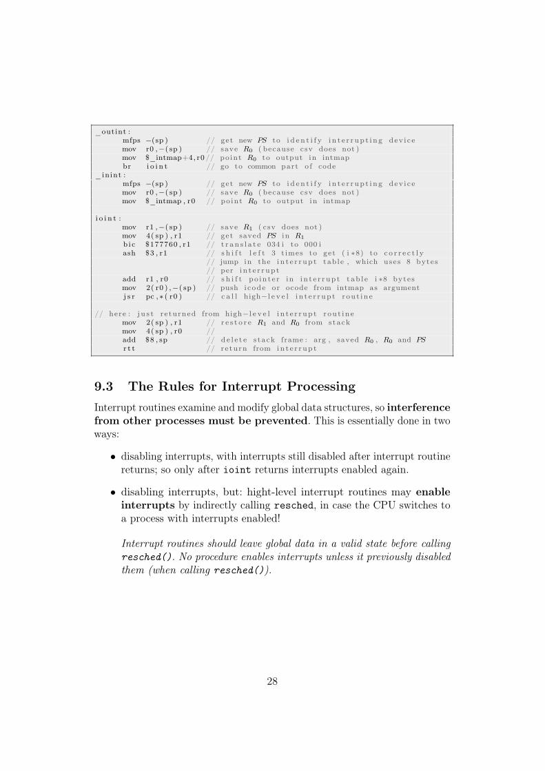
9.1 Dispatching InterruptsTwo-Level-strategy to handle interrupts:
1. interrupts branch to low-level interrupts dispatch routine writtenin assembly language, they
• save and restore R0 and R1
• identify the interrupting device
• handle return from interrupt
• and call the second level:
2. high-level interrupt routines (for r/t, i/o passing, disc processing),written in C
In Xinu there are three interrupt dispatchers22: clock interrupts, input- andoutput-interrupts.
How is the interrupting device identified? At the interrupt vector addressthe PC (address of interrupt dispatch routine) and the PS (0341 for device1, 034i for device i (i = 0, . . . , 15) is stored, the PS is used to identify thedevice.
9.2 Input and Output Interrupt DispatchersThe interrupt dispatchers assume that the PC and the PS are on top ofthe stack upon entry. Low order 4 bits of the current PS contain the devicedescriptor. Interrupts are disabled.
22Man sollte immer auch den Text lesen, der Text ist immer besser als mein Vortrag -das ist der Nachteil, wenn man ein gutes Buch liest.
27
_outint :mfps −(sp ) // get new PS to i d e n t i f y i n t e r r up t i n g dev i cemov r0 ,−( sp ) // save R0 ( because csv does not )mov $_intmap+4, r0 // po int R0 to output in intmapbr i o i n t // go to common part o f code
_inint :mfps −(sp ) // get new PS to i d e n t i f y i n t e r r up t i n g dev i cemov r0 ,−( sp ) // save R0 ( because csv does not )mov $_intmap , r0 // po int R0 to output in intmap
i o i n t :mov r1 ,−( sp ) // save R1 ( csv does not )mov 4( sp ) , r1 // get saved PS in R1
b i c $177760 , r1 // t r a n s l a t e 034 i to 000 iash $3 , r1 // s h i f t l e f t 3 t imes to get ( i ∗8) to c o r r e c t l y
// jump in the i n t e r r up t tab le , which uses 8 bytes// per i n t e r r up t
add r1 , r0 // s h i f t po in t e r in i n t e r r up t t ab l e i ∗8 bytesmov 2( r0 ) ,−( sp ) // push i code or ocode from intmap as argumentj s r pc , ∗ ( r0 ) // c a l l high−l e v e l i n t e r r up t rou t ine
// here : j u s t returned from high−l e v e l i n t e r r up t rou t inemov 2( sp ) , r1 // r e s t o r e R1 and R0 from stackmov 4( sp ) , r0 //add $8 , sp // d e l e t e s tack frame : arg , saved R0 , R0 and PSr t t // re turn from in t e r r up t
9.3 The Rules for Interrupt ProcessingInterrupt routines examine and modify global data structures, so interferencefrom other processes must be prevented. This is essentially done in twoways:
• disabling interrupts, with interrupts still disabled after interrupt routinereturns; so only after ioint returns interrupts enabled again.
• disabling interrupts, but: hight-level interrupt routines may enableinterrupts by indirectly calling resched, in case the CPU switches toa process with interrupts enabled!
Interrupt routines should leave global data in a valid state before callingresched(). No procedure enables interrupts unless it previously disabledthem (when calling resched()).
28
10 Real-Time Clock Management
10.1 The Real-Time Clock MechanismThree kinds of clocks associated with a computer23:
1. central system clock: controlling the rate the CPU executes instructions(belongs to MHz or FSB or so)
2. real-time clock: pulsing regularly an integral number of times eachsecond, signalling the CPU each time a pulse occurs by posting aninterrupt
3. time-of-day clock: a chronometer like a watch, the CPU controls thisclock
The real-time clock does not contain a counter (con to the time-of-day clock),does not accumulate interrupts (left to the system) and controls the CPU.Responsibility for counting interrupts falls upon the system:
If the CPU takes too long to service a real-time clock interrupts, of if itoperates with interrupts disabled for more than one clock cycle, it willmiss the interrupt.
So systems must be designed to service clock interrupts quickly.
10.2 Optimization of Clock Interrupt ProcessingEffective clock ratio has to be adjusted to match the system - how is thisdone in Xinu? The clock interrupt handler/dispatcher clkint simulates aslower-rate clock by dividing the clock rate: The LSI 11/2 real-time clockgenerates 60 pulses per second and clkint ignores 5 clock interrupts in a rowby serving them not at all (very quickly!) before processing the 6th one.This reduces the effective clock rate, called the tick rate.
10.3 The use of the real-time clockOperating Systems use real-time clocks to compute the time-slices allotted forthe execution of each process by scheduling a pre-emption event. This eventis used to prevent processes from running forever. It is set in resched() bypreempt = QUANTUM; (see page 58) The clock interrupt dispatcher effcint
23zu Hause angucken: Befehle mov ri,-(sp) und mov (sp)+,ri für i = 0,1 in clkint.s,möglicherweise wichtig für Klausur!
29
decrements preempt on each tick, calling resched() when preempt = 0.
The Operating System also provides processes with timed delays: The systemmaintains a list of processes, ordered by the time they should be awakened.When the real-time clock interrupts, it examines this list and wakes upprocesses for wich the delay has expired. A preemption
10.4 Delta List ProcessingBecause it cannot afford to search through long lists of sleeping processes tofind those that should awaken on each clock tick, the system keeps sleepingprocesses in a data structure called a delta list :
Processes on clockq are ordered by the time at which they will awaken:each key tells the number of clock ticks that the process must delaybeyond the preceding one on the list
Example waiting times: P1 = 5, P2 = 27, P3 = 28, P4 = 28, P5 = 35. TheQ-Structure used to save this data:
head −→ P1 : 5 −→ P2 : 22 −→ P3 : 1 −→ P4 : 0 −→ P5 : 7 −→ tail
10.5 Putting a Process to SleepSystem call sleep10(n) delays the calling (current) process for n tenth-of-a-second, by moving the current process to the delta list clockq. This requiresintroducing a new process state for that moved process: SLEEPING (see figure10.1).
10.6 Delays measured in SecondsThe size of integer (16 bits) limits the delay time of sleep10(n) to approx. 55minutes. System call sleep(n), which puts a process to sleep for n seconds,provides a way to delay up to 9 hours.
10.7 Awaking Sleeping Processesthat clkint decrements the count of the first key on clockq at each time,until this key equals 0 at which time the hight-level interrupt procedurewake-up() is called, to put processes with key = 0 on to ready list.
30
10.8 Deferred Clock ProcessingThe deferred mode allows the system to accumulate clock-ticks in varclkdiff without initiating events. I.e., it postpones the reaction uponrealtime-clock interrupts. The clock handler can schedule events that shouldhave occurred as soon as it leaves deferred mode and returns to original mode.
10.8.1 Procedures for Changing to and from Deferred Mode
A process can place the clock in deferred mode by calling STOPCLK andreturn the clock to real-time mode by calling STRTCLK. STOPCLK countsdeferral requests by incrementing defclk; STRTCLK counts restart requestsby decrementing defclk. As long as defclk remains positive, the interruptshandler counts clock ticks in clkdiff without processing them.
10.9 Clock Interrupt Processing
10.10 Clock InitializationTo determine if the system has a real-time clock, setclkr(); runs througha loop 30.000 times. If there’s a real-time clock, it should at least onceinterrupts this loop24. So the interrupt handler is temporarily overwrittenwith a procedure which enables the clock.25
10.11 Summary
11 Device independent Input and OutputOperating Systems control the I/O-devices for three reasons:
1. The hardware interface to such devices is crude, requiring complexsoftware packets for their control, called device drivers.
2. Device drivers are shared resources, which need to be protected andallocated in a fair and safe way.
3. A uniform, flexible interface should be provided, a high-level inter-face, allowing users to write programs without knowing the machineconfiguration.
24„Das ist das Schöne an System Programming: Die richtige Lösung ist immer kurz.“25„Also ein bißchen studieren zu Hause und Kai Baukus lieb angucken. Er guckt schon
dunkel, er kann’s auch nicht lesen.“
31
Focus of this chapter: The selection of a set of machine-independent high-level I/O primitives and the data structure required to implement theseprimitives to specific devices.
How are these primitives selected? By generating a list of desirableproperties, deriving a set of high-level primitives, and giving their meaningwith respect to certain abstract (classes of) devices, for example terminals,discs etc. The last step is to build software mapping the abstract devices toparticular instances of that device.
11.1 Properties of the input and output interfaceQuestion: Should processes block while performing I/O operations (synchro-nous operations) or should they continue executing and be notified when theoperation completes (asynchronous operations)? Asynchronous operations areuseful for controlling overlap, i.e. more parallelism of comp and I/O operations.Synchronous operations delay input operations until data arrives and delaysoutput operations until data has been consumed. Their advantage is thatusers can depend on data immediately after an input operations and changedata immediately after an output operation.
Also a question: which format does the data have? Single-byte transfer (tele-type terminals, e.g. console) or block mode (a block of many bytes like on adisk)?
11.2 abstract Operations• getc and putc deal with single-character transfer (read or display one
character)
• read and write deal with transfer to/from contiguous blocks of memory
• control allows control of the device (driver), e.g. whether the systemechoes each character as it is typed on the keyboard
• seek applies only to randomly accessible memory and then searches fora particular position
• open and close inform device (driver) that data transfer will begin orhas ended (applies to disk and file access)
• init initializes the device and device driver at system’s startup
32
11.3 Binding abstract Operations to Real DevicesThe system maps these high-level I/O operations to specific device drivers: ithides the details of the hardware and the device drivers and it makes theprograms independent of the particular hardware configuration.
The high-level calls of these operations constitute the environment whichthe system presents to running programs - i.e. the programs only see theperipheral devices through these abstract calls.
The system also maps abstract names to real devices.26
Coded into the system is a description of each abstract device, e.g. thedevice driver routines which it uses, the address of the real device to which itcorresponds. When a new device is added to the system, or, e.g., the deviceaddresses are modified, the system must be altered and recompiled.
11.4 Binding I/O calls to Device Drivers at Run-TimeRotines like read in the compiled code should map abstract device descriptors,s.a. console, to device driver routines and real device addresses. In Xinu,each abstract device is assigned an integer device descriptor (0, . . . , 8) atsystem configuration. E.g., console has the same device descriptor in allXinu systems.
In the device switch table, each entry corresponds to a single device,containing:
• dvnum: the corresponding entry into the interrupt dispatch table intmap
• address of the device driver routines for that device (dvgetc, dvputc,dvread, dvwrite, dvcontrl, dvseek, dvinit)
• device address and other info, since more than one device can use thesame device driver
Device switch table also contains27:
• hardware device addresses (dvcsr)
• interrupt vector addresses (dvivec, dvovec)26Zur seitenlangen Liste in conf.h: „Ich werde keinem den Kopf abhacken, wenn er diese
Liste nicht kann in der Prüfung!“27Zu einem, der gesappelt hat: „Dann geh mal zu einem anderen Professor, so Kluge zum
Beispiel, da bekommst Du gleich ’ne Fünf!“
33
• the interrupt routines for input (dviint) and output (dvioblk)
• buffer pointer dvioblk
• an integer dvminor distinguishing among multiple copies of a device28
11.5 Implementation of high-level I/O-operationsThere is a procedure for each of the abstract operations getc, putc, read,and so on. They call low-level device drivers indirectly through the deviceswitch table. For example, the C code in file read.c implements the readoperation:read ( int descrp , char ∗buf f , int count ) {
. . .devptr = &devtab [ descrp ] ;return ( (∗ devptr−>dvread ) ( devptr , buf f , count ) ) ;
}
11.6 Opening and Closing DevicesSome disk devices require the programs to start them before performikng atransfer operations, and to stop them when the transfer completes.
11.7 Null and Error Entries in Device TableNot all combinations of operations and device descriptors are meaningful:
• ionull() signifies an unneccessary byte (e.g., open a console), returnsOK
• ioerr() signifies an illegal operation (e.g., seek on a console), returnsSYSERR
11.8 Initialization of the I/O SystemThe device table devtab is generated when the system in configured, so it iscompletely filled in by the time the system is compiled. Generating the fileconf.h is discussed in chapter 20.
28„Ich habe am Wochenende „Superstar“ geguckt. Ich habe gemerkt, daß ich eine lauteStimme habe - schade, daß ich, als ich jung war, nicht mitgemacht habe. Also: Ich wäre einguter Sänger gewesen.“
34
11.9 Interrupt vector InitializationInterrupt vectors and the interrupt dispatch table29 intmap are initialized atruntime, using the information in devtab. The system calls init(k) for eachdevice k at startup, before it starts executing the user’s program (done inchapter (13)).
The device table forms the general framework for linking interrupts,devices and device driver routines.
12 An Example Device DriverThis chapter discusses the device driver routines for a standard computerterminal with a keyboard, called teletype or tty.
12.1 The device type tty
To minimize the interference between I/O devices and running processes, thedriver uses interrupts-driven processing to
• transmit characters when serial line unit (SLU) is idle
• read characters when these are received by the unit
• handle details like receiver errors
The tty driver operates using parameters, so it can be used for a variety ofterminals in a variety of system configurations. E.g., several parameters controlthe echo of characters typed on the keyboard onto the screen (full-duplexmode: do not display characters as the user types them; half-duplex mode:directly echo keystrokes). There are other parameters concerning unprintablechars as printable combinations (to move to a new line, terminal must receiveboth newline and return).
12.2 Upper and Lower Halves of the Device DriverA device driver is a set of procedures controlling a peripheral hardware device.It’s routines are partitioned into
• upper-half device driver : called from user programs29„Pro Minute für Studenten: 10 EUR. Mein Gehalt staffelt sich nach den Minuten, die
ich vorlese. Ein bißchen dumm, aber so ist das deutsche Gesetz.“
35
• lower-half device driver : handling device interrupts
These two halves communicated via a shared data structure, the device controlblock.
Upper-half routines enqueue requests for data transfer or device control;they do not interact with devices directly. Lower-half routines transferdata from buffers or control devices; they do not interact with userprograms directly.
12.3 Synchronization of the Upper and Lower HalvesOutput operations issued by the calling user process are deposited as to bewritten characters in the output buffer, and return to the caller.
Whenever the SLU receiver interrupts after it has received a character, theinterrupt dispatcher calls the lower-half input interrupt routine. The lower-level interrupt input handler reads the waiting character and deposits it inthe circular buffer. A process waiting for input from the (empty) circularbuffer is started as soon as the next character arrives.30
12.4 Control Block and Buffer DeclarationsBoth lower-half of the device driver and the ... use the minor device numberas an index in the array of tty-structures.
12.5 Upper-Half tty Input Routines
12.6 Upper-Half tty Output Routines
12.7 Lower-Half tty Driver Routines12.7.1 Watermarks and Delayed Signals
12.7.2 Lower-Half Input Processing
Input interrupt processing is more complex because it cares for characterecho, line editing, processing of input errors and buffer overflow. It operatesin one of the following three modes:
• raw: accumulates chars in input buffer without further processing30„. . . Signatur „Rembrandt Kai Baukus“ . . . “
36
• cooked: does character echo, honors suspend or restart output, accumu-lates full lines before passing them on to upper-half routines, honoresinput editing by erasing previous chars or killing entire lines
• cbreak: honors control chars but does no line editing
12.7.3 cooked Mode and cbreak-Mode Processing
12.8 tty Control Block Initialization
12.9 Device Driver Control
12.10 Summary
13 System InitializationMany microcomputers require no more than what’s been discussed in chapters1 to 12.How does CPU know when a character is received in RBUF-field of CSR, orwhen a character has been sent after having been placed in XBUF-field of CSR?It uses one of two techniques: Polled I/O or interrupts-driven I/O. Polling isused for initialization or debugging because based on busy-waiting: It requiresCPU to check device repeatedly until it finds a character is waiting or hasbeen sent.
• RCSR: Bit 7 whether character received along Serial Line Unit, Bit 6Serial Line Unit will post interrupt when character received in RBUF
• XCSR: Bit 7 when character has been transmitted, Bit 6 Serial LineUnit will post interrupt when character has been sent, Bit 0 transmitteris forced in BREAK condition; must be set to 0 to clear break condition
13.1 Starting from ScratchA crash occurs when hardware executes an ivali operation, caused becausecode or data in the OS has been destroyed. A crash means the contents ofmemory have been corrupted or lost!
How can a machine, devoid of valid programs, spring into action andbegin executing? It cannot!
Somehow a program must be deposited in memory before the machine canstart. On the oldest cptrs this happend by hand, using switches. Later
37
standard keyboards built to that purpose, i.e. special terminals, now micro-and mini-computers are used to load the initial program from disk or tapestorage attached to the system.
Once the initial program has been loaded, the CPU can executed the startupprogram which reads a larger program (usually from a specific location on aspecific disk). Then the CPU branches to a larger program which reads theentire OS into memory and braches to the later’s beginning. This process iscalled rebooting the system.
The main goal of the chapter is to explain the steps necessary to transformthe single, sequential program into a operating system.
13.2 Booting Xinu
Xinu is downloaded from another computer in the following steps:
1. Host computer generates a break condition to halt the 11/2 processor.
2. 11/2 responds in Octal Debugging Technique (ODT) mode; it sendsa prompt and recognizes commands to display and change memorylocations and registers.
3. Hosts loads initial program in 11/2 memory starting at location 0, andstarts 11/2 executing it.
4. initial boot program reads characters, using polled I/O, and depositsthem in memory starting at highest location. Host sends second bootprogram to 11/2.
5. When finished, host sends a break, forcing 11/2 into ODT mode.
6. When ODT responds, hosts starts executing on 11/2 of second bootprogram.
7. Host and second boot program communicate, with the host sending„packtes“ of bytes (one-at-a-time), and boot programm acknowledgingreceipt or requesting transmission
8. Host (either) tells second bootstrap to branch to the start of Xinu (orto halt and await ODT commands)
9. Host directs second bootstrap to branch to Xinu, and CPU beginsexecuting start program.31
31Zu einem, der zu spät kommt: „Noch so ein Kraftprotz, der alles schon kennt“
38
13.3 System StartupThe startup program32
13.4 Finding the size of MemoryAt label start, Xinu is creating a valid runtime environment for C bysetting Stack Pointer to the highest available Memory Address. This is doneby try-and-error (with interrupts).33
13.5 Initializing System Data Structures
13.6 Transforming the Program into a Process
13.7 The Map of Low Core
13.8 Summary
17 A Disk DriverAt the level of device driver routines, a disk is viewed as a randomly accessiblearray of blocks (here, of size 512 bytes). The interaction between driversoftware and the disk device itself is more complicated than for a serial lineunit. Therefore, an extra controller (disk-controller) is needed with its ownformat of controller request records (see page 34, figure 2.11).
A disk is a random access device. Therefore, a disk must position the diskarm as well as transfer data. Disk hardware uses direct-memory-access mode(DMA), allowing for the direct transfer to/from memory blocks without helpfrom the CPU. So it does not interrupt the CPU for the transfer of everysingle character. Hence CPU can continue operation while block transfer takesplace.A disk consists of
• a disk drive (i.e., platters (spindle) which rotates at a high speed, anda physical arm)
• an electronic controller (contains microprocessor(s), positions disk arm,controls transfer of data, can operate multiple disk drives (but not ableto transfer data to/from one diskplatter simultaneously))
32„Was ist das für eine Zahl? Das ist keine Macht von Zwo!“33Machst Du auch so einen Kurs, wo man lernt, wie man Männern in die Eier tritt? Das
muß man nämlich lernen!
39
• a host interface (connects controller to system bus, passes requests foran I/O operation from processor to controller)
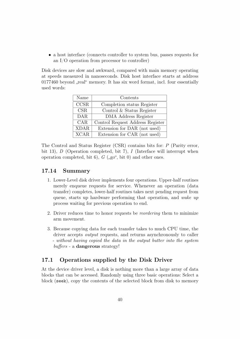
Disk devices are slow and awkward, compared with main memory operatingat speeds measured in nanoseconds. Disk host interface starts at address0177460 beyond „real“ memory. It has six word format, incl. four essentiallyused words:
Name ContentsCCSR Completion status RegisterCSR Control & Status RegisterDAR DMA Address RegisterCAR Control Request Address RegisterXDAR Extension for DAR (not used)XCAR Extension for CAR (not used)
The Control and Status Register (CSR) contains bits for: P (Parity error,bit 13), D (Operation completed, bit 7), I (Interface will interrupt whenoperation completed, bit 6), G („go“, bit 0) and other ones.
17.14 Summary1. Lower-Level disk driver implements four operations. Upper-half routines
merely enqueue requests for service. Whenever an operation (datatransfer) completes, lower-half routines takes next pending request fromqueue, starts up hardware performing that operation, and wake upprocess waiting for previous operation to end.
2. Driver reduces time to honor requests be reordering them to minimizearm movement.
3. Because copying data for each transfer takes to much CPU time, thedriver accepts output requests, and returns asynchronously to caller- without having copied the data in the output butter into the systembuffers - a dangerous strategy!
17.1 Operations supplied by the Disk DriverAt the device driver level, a disk is nothing more than a large array of datablocks that can be accessed. Randomly using three basic operations: Select ablock (seek), copy the contents of the selected block from disk to memory
40
(read) and copy the contents of memory to the selected block on disk (write).
Format of instructions: read(DISKDEV, buff, blocknr) means „read diskblock with nr. blocknr into memory starting at address buff“. So, why isoperation seek needed? To optimalize disk access!
17.2 Controller Request and Interface Register Des-criptors
The Xebec Disk Controller Layout is described by structure xbdcb on page284 and 285, corresponding to figure 2.11. Notice the many possible operationslisted on page 285! For us, only XOREAD, XOWRITE and XOSEEK are interesting.The disk controller host interface on page 286 parallels figure 2.12. Notice thatthe bits in figure 2.13 correspond to operations DTGO (set bit nr. 0), DTRESET(bit 1), DTINTR (bit 6), DTDONE (bit 7) and DTERROR (bit 15).
17.3 The List of pending Disk RequestsFor disks, the requeired infor for transfer between upper- and lower-level rou-tines resides in control blocks. Disk driver control blocks: dstab[], consistingof structures dsblk, containing:
• dvioblk: should contain address or control block
• dcsr: should contain address of host interface
• dreqlst: DRNULL
• dibsem: semaphore dealing with access to the index block list in filesystem
• dflsem: semaphore dealing with access to the free list of data blocks infile system
• ddirsem: semaphore dealing for directory access in the file system
• dnfiles: number of open files, initially 0
• ddir: address for incore memory for the data directory: getbuf(dskdbp)(disk data block buffer pool)
41
17.4 Enqueuing Disk RequestsThe disk driver maintains the following invariant:
The first request on the pending request list is always the one the hard-ware is performing, if the list is empty, the hardware is idle.
The lower-half records info about errors occurred, the upper-half extractsthat info and passes it to the caller.
The disk driver processes I/O requests in fht order in which they occuron the request list. When one completes, it is removed from the list andthe next one is started. When procedure dskenq adds a request for blockB to the existing list of requests, it schedules it to be performed betweenrequests i and i + 1, if the disk arm will pass over block B on itsway from i to i + 1.
17.5 Optimizing the Request QueueIn case of a read operation to be enqueued for which there is a write for thesame block in the list of pending requests, the read operation. . .
17.6 Starting a Disk OperationProcedure dskstrt on page 294 starts a disk operation by building a controllerrequest structure in the ddcb field of the disk control block, feeding thatrequest to the controller through the interface.
17.7 The upper-half read Routine
17.8 Driver InitializationProcedure dsinit fills in the disk control block, fills in the correspondinginterrupts vectors and the corresponding entries into the interrupt dispatchtable by calling iosetvec, sets up a read command for the desk directoryto be read. Because the system executes the initialization routine beforeinterrupts are enabled, disk initialization runs in polled mode.
42
17.9 The upper-half output Routine
17.10 The upper-half output Routine
17.11 The upper-half seek Routine
17.12 The lower-half of the Disk Driver
17.13 Flushing Pending Requests
43