information · 2015-01-09 · ec directives ... rated current based on the time characteristics...
TRANSCRIPT

246
A5 Fam
ilyE Series
Information
Information
Contents
A5 Family.................................................................................................................247 EC Directives ........................................................................................................247
Conformity to UL Standards ..................................................................................247
Composition of Peripheral Equipments ................................................................249
E Series ...................................................................................................................255 Compliance to EC and EMC Directives ................................................................255
Composition of Peripheral Components ...............................................................255
Conformity to UL Standards ..................................................................................256
Motor capacity selection software ........................................................................257 AC Servo Motor Capacity Selection Software ......................................................257
Option Selection Software for AC Servo Motor .....................................................257
Guide to the International System of Units (SI) ...................................................258
Selecting Motor Capacity.......................................................................................260
Request Sheet for Motor Selection .......................................................................266
Connection Between Driver and Controller .........................................................274 Connection Between A5 Family Driver and Controller. .........................................274
Replacing Old Model Servo Driver with MINAS A5Ⅱ and A5 Series .....................279
Connection Between E Series Driver and Controller. ...........................................283
Index .........................................................................................................................288
Sales Office ..............................................................................................................305

247 248
A5 Fam
ilyE Series
Information
000A5 Family
Conformance toInternational Standards
A5 FamilyEC Directives/Conformity to UL Standards/KC
EC DirectivesThe EC Directives apply to all such electronic products as those having specific functions and have been exported to EU and directly sold to general consumers. Those products are required to conform to the EU unified standards and to furnish the CE marking on the products.However, our AC servos meet the relevant EC Directives for Low Voltage Equipment so that the machine or equipment comprising our AC servos can meet EC Directives.
EMC DirectivesMINAS Servo System conforms to relevant standard under EMC Directives setting up certain model (condition) with certain locating distance and wiring of the servo motor and the driver. And actual working condition often differs from this model condition especially in wiring and grounding. Therefore, in order for the machine to conform to the EMC Directives, especially for noise emission and noise terminal voltage, it is necessary to examine the machine incorporating our servos.
Conformity to UL StandardsObserve the following conditions of (1) and (2) to make the system conform to UL508C (E164620).(1) Use the driver in an environment of Pollution Degree 2 or 1 prescribed in IEC60664-1. (e.g. Install in the control box with IP54 enclosure.)(2) Make sure to install a circuit breaker or fuse which are UL recognized (Listed marked) between the
power supply and the noise filter. For rated current of circuit breaker and fuse, refer to P.19 “Driver and List of Applicable Peripheral Equip-
ments”. Use a copper cable with temperature rating of 75 ˚C or higher.(3) Over-load protection level Over-load protective function will be activated when the effective current exceeds 115 % or more than the
rated current based on the time characteristics (see the graph). Confirm that the effective current of the driver does not exceed the rated current.
Set up the peak permissible cur-rent with Pr0.13 (Setup of 1st torque limit) and Pr5.22 (Setup 2nd torque limit).
Conformed Standards
Driver Motor
EC Directives
EMC Directives
EN55011EN61000-6-2EN61800-3
—
Low-VoltageDirectives EN61800-5-1
EN60034-1EN60034-5
MachineryDirectives
Functionalsafety *1
ISO13849-1(PL d)(Cat.3)EN61508(SIL2)EN62061(SILCL 2)EN61800-5-2(STO)IEC61326-3-1
—
UL Standards UL508C (E164620)
UL1004-1 E327868: 50 W to 750 W( 6.0 kW to 15.0 kW)UL1004 E327868: 400 W(400 V), 600 W(400 V),( 750 W(400 V), 0.9 kW to 5.0 kW)
CSA Standards C22.2 No.14 C22.2 No.100
Korea Radio Law (KC) *2 KN11 KN61000-4-2, 3, 4, 5, 6, 8, 11
—
IEC : International Electrotechnical CommissionEN : Europaischen NormenEMC : Electromagnetic CompatibilityUL : Underwriters LaboratoriesCSA : Canadian Standards Association
Pursuant to the directive 2004/108/EC, article 9(2) Panasonic Testing Centre Panasonic Service Europe, a division of Panasonic Marketing Europe GmbH Winsbergring 15, 22525 Hamburg, F.R. Germany
● When export this product, follow statutory provisions of the destination country.*1 A5ⅡE and A5E series doesn't correspond to the functional safety standard. *2 Information related to the Korea Radio Law This servo driver is a Class A commercial broadcasting radio wave generator not designed for home use. The user and
dealer should be aware of this fact.
Servo Driver
Time [s]
Overload protection time characteristics
MSME 50 WMSME 100 W (100 V)
MSME 100 W (200 V)
MSME 200 WMSME 400 W
MSME 750 W (200 V)
MSME 750 W (400 V), 1.0 kW to 5.0 kWMDME 400 W to 15.0 kWMHME 1.0 kW to 7.5 kWMGME 0.9 kW to 6.0 kW
100115
0.1
1
10
100
200 300 400 500Torque [%]
Time [s]
100115
0.1
1
10
100
200 300 400 500Torque [%]
• Motor type: M□MD
• Motor type: M□ME
MSMD 50 WMSMD 100 W (100 V)
MSMD 100 W (200 V)
MSMD 200 WMHMD 200 WMSMD 400 WMHMD 400 W
MSMD 750 WMHMD 750 W

249 250
A5 Fam
ilyE Series
Information
Composition of Peripheral EquipmentsConformance toInternational Standards
A5 Family
Installation EnvironmentUse the servo driver in the environment of Pollution Degree 1 or 2 prescribed in IEC-60664-1 (e.g. Install the driver in control panel with IP54 protection structure.)
Metaric control box<100 V/200 V>
Controller
PC
Insulated power supply for interface Safety
controller
Power supply Residual
current device(RCD)
Surge absorber
Noise filter
Noise filter for signal lines Noise filter for signal linesNoise filter for
signal lines
Noise filter for signal lines
Protective earth (PE)
L1U
X4
XA
M
RE
VW
L2L3L1CL2C
Driver
MotorX1
X6X3
XBCircuit breaker
Noise filter for signal lines
Noise filter for signal lines
For to , refer to the Table “Noise Filter for Signal Line” (P.254).* A5ⅡE, A5E is not provided with X3 terminal.
A to F-frame:Motor cablewithout shieldcableG, H-frame:Motor cablewith shieldcable
*
InsulatedDC24 V
NF1
NF3
NF1 NF3
For to , refer to the Table “Noise Filter for Signal Line” (P.254).* A5ⅡE, A5E is not provided with X3 terminal.
NF1 NF3
NF3NF3
NF3
NF2
Metaric control box<400 V>
Controller
PC
Insulated power supply for interface Safety
controller
Power supply Residual
current device(RCD)
Surge absorber
Noise filter
Noise filter for signal lines Noise filter for signal linesNoise filter for
signal lines
Noise filter for signal lines
Protective earth (PE)
L1U
X4
XA
M
RE
VW
L2L324V0V
Driver
MotorX1
X6X3
XBCircuit breaker
Noise filter for signal lines
Noise filter for signal lines
D to F-frame:Motor cablewithout shieldcableG, H-frame:Motor cablewith shieldcable
*
NF1
NF3
NF3NF3
NF3
NF2
<Caution>Use options correctly after reading Operating Instructions of the options to better understand the precautions. Take care not to apply excessive stress to each optional part.
Power Supply
100 V type(A to C-frame) Single phase, 100 V
+10 %–15 % to 120 V
+10 %–15 % 50/60 Hz
200 V type(A to D-frame) Single/3-phase, 200 V
+10 %–15 % to 240 V
+10 %–15 % 50/60 Hz
200 V type(E to H-frame) 3-phase, 200 V
+10 %–15 % to 230 V
+10 %–15 % 50/60 Hz
400 V type[Main power supply]
(D to H-frame) 3-phase, 380 V
+10 %–15 % to 480 V
+10 %–15 % 50/60 Hz
400 V type [Control power supply]
(D to H-frame)DC 24 V ±15 %
(1) This product is designed to be used in over-voltage category (installation category) Ⅲ of EN 61800-5-1:2007.(2) Use an insulated power supply of DC12 V to 24 V which has CE marking or complies with EN60950.
Circuit BreakerInstall a circuit breaker which complies with IEC Standards and UL recognized (Listed and marked) between power supply and noise filter.The short-circuit protection circuit on the product is not for protection of branch circuit.The branch circuit should be protected in accordance with NEC and the applicable local regulations in your area.
Noise FilterWhen you install one noise filter at the power supply for multi-axes application, contact the manufacturer of the noise filter. If noise margin is required, connect 2 filters in series to emphasize effectiveness.• Options
Option part No. Voltage specifications for driver
Manufacturer'spart No.
Applicable driver (frame) Manufacturer
DV0P4170 Single phase 100 V, 200 V SUP-EK5-ER-6 A and B-frame Okaya Electric Ind.
[Unit: mm]
Label
Terminal cover (transparent)
2 – ø4.5
R Cx CxCy
L L
Cy
2 – ø4.5 x 6.75
53.1±1.0
100.0 ± 2.088.075.0 5.0
12.0
10.0
50.0
60.0
7.0
2.0
(11.6)(13.0)
6 – M4
2
1 3
4
Circuit diagramIN OUT
Option part No. Voltage specifications for driver
Manufacturer'spart No.
Applicable driver (frame) Manufacturer
DV0PM200423-phase 200 V
3SUP-HU10-ER-6A and B-frame
Okaya Electric Ind.Single phase 100 V, 200 V
3-phase 200 V C-frame
DV0P4220 Single/3-phase 200 V 3SUP-HU30-ER-6 D-frameDV0PM20043 3-phase 200 V 3SUP-HU50-ER-6 E-frame
A B C D E F G H115DV0PM20042
[DV0PM20042, DV0P4220] [DV0PM20043]
105 95 70 43 10 52 5.5145DV0P4220 135 125 70 50 10 52 5.5165DV0PM20043 136 165 90 80 40 54 5.5
Label
ABC H
10 F
EDG
Earth terminalM4
M4
Screw for coverM3
Cover
Body
4
5
1
2
63
Circuit diagram
L1
Cx1
IN OUT
R Cx1
Cy1
[Size] [Unit: mm]
Label
A
CB
H
M5
E
F
D
Earth terminalM4
Screw for coverM3
G
Cover
Body
For single phase application, use 2 terminals among 3 terminals, leaving the remaining terminal unconnected.

251 252
A5 Fam
ilyE Series
Information
Composition of Peripheral EquipmentsConformance toInternational Standards
A5 Family
Option part No. Voltage specifications for driver
Manufacturer'spart No.
Applicable driver (frame) Manufacturer
DV0P3410 3-phase 200 V 3SUP-HL50-ER-6B F-frame Okaya Electric Ind.
[Unit: mm]
Circuit diagramIN OUT
286±3.0
1502-ø5.5 x 7 2-ø5.5
6-6M
270255±1.0
240
120
90±1
.0(18)
(13)
Label
1
2
3
4
5
6
• Recommended components
Part No. Voltage
specifications for driver
Current rating(A)
Applicable driver (frame) Manufacturer
RTHN-50103-phase 200 V
10 A, B, C-frameTDK-Lambda Corp.RTHN-5030 30 D-frame
RTHN-5050 50 E, F-frame
[RTHN-5010]195±1210±2
50±2
6-M4M44.5
10±1
18.5
±178±1
4.5±
195±2 18
.5±1
[RTHN-5030]225±1240±2
55±2
6-M4M44.5
10±1
18.5
±185±1
4.5±
1105±
2 18.5
±1[RTHN-5050]
280±1300±2
68±2
6-M5M45.5
12.5
±1
21±1102±
15.
5±112
8±2 21
±1
[Unit: mm]
[Unit: mm]
[Unit: mm]
<Remarks>• Select a noise filter of capacity that exceeds the capacity of the power source (also check for load condition).• For detailed specification of the filter, contact the manufacturer.• When two or more servo drivers are used with a single noise filter at the common power source, consult with
the noise filter manufacturer.
Part No. Voltage specifications for driver
Current rating(A)
Applicable driver (frame) Manufacturer
FS5559-60-343-phase 200 V
60 G-frame
Schaffner EMC, Inc.
FS5559-80-34 80 H-frameFN258L-16-07
3-phase 400 V
16 D, E-frameFN258L-30-07 30 F-frameFN258-42-07 42
G, H-frameFN258-42-33 42
[Unit: mm]
[Unit: mm] [Unit: mm]
[Size]
PE
LINE
L1
L3
L2
L1'
L3'
L2'
LOAD
C
5050
140
6.5 D
A
9525 1.
5
M8 25
B
Circuit diagram
Circuit diagram Circuit diagram
A B C D410FS5559-60-34 170 370 388460FS5559-80-34 180 420 438
[FS5559-60-34, FS5559-80-34]
[FN258L-16-07] [FN258L-30-07]
Litze AWG14M5
275
55290
305
142
150
30
6.5
6.5
300`10 305
320
335344.5
400`1099
47nF(Y2)
3x1,5MΩ3x2,2µF(X2)
3x1,5µF(X2)
3x1mH3x2mH
3x2,2µF(X2)E
L3'
L2'
L1'
E
L3
L2
L1
LOAD
LIN
E
Litze AWG10M5
35
60
47nF(Y2)SH
3x1,5MΩ3x2,2µF(X2)SH
3x2,2µF(X2)SH
3x0,65mH3x1,35mH
3x2,2µF(X2)SHE
L1'
L2'
L3'
E
L1
L2
L3
LOAD
LIN
E
LINE LOAD
Circuit diagram
[FN258-42-07] [FN258-42-33]
E E
L3
L2
L1
L3'
L2'
L1'
314
300
329
1.5
70
500±10
45
6.5
12
185
350
70314
329
45 6.5
300
185
1.5
[Unit: mm][Unit: mm]
<Remarks>• Select a noise filter of capacity that exceeds the capacity of the power source (also check for load condition).• For detailed specification of the filter, contact the manufacturer.• When two or more servo drivers are used with a single noise filter at the common power source, consult with
the noise filter manufacturer.

253 254
A5 Fam
ilyE Series
Information
Composition of Peripheral EquipmentsConformance toInternational Standards
A5 Family
Surge AbsorberProvide a surge absorber for the primary side of noise filter.
Option part No. Voltage specifications for driver
Manufacturer'spart No. Manufacturer
DV0P1450 3-phase 200 V R・A・V-781BXZ-4Okaya Electric Ind.
DV0PM20050 3-phase 400 V R・A・V-801BXZ-4
Circuit diagram
1
φ4.2±0.2
41±1
UL-1015 AWG16
28±1
5.5±
111
±128
.5±1
4.5±
0.5
200
+30
-0
2 3
[Unit: mm]
① ② ③
Option part No. Voltage specifications for driver
Manufacturer'spart No. Manufacturer
DV0P4190 Single phase 100 V, 200 V R・A・V-781BWZ-4 Okaya Electric Ind.
Circuit diagramφ4.2±0.2
41±1
UL-1015 AWG16
28±1
5.5±
111
±128
.5±1
4.5±
0.5
200
+30
-0
1 2
[Unit: mm]
① ②
Noise Filter for Signal LinesInstall noise filters for signal lines to all cables (power cable, motor cable, encoder cable and interface cable)
Symbol*1 Cable Name100 V/200 VAmp. frame
symbol
400 VAmp. frame
symbolOption
part No.Manufacturer's
part No. Manufacturer Qty.
NF1 Power cable
A, B, C, D D, E, F DV0P1460 ZCAT3035-1330 TDK Corp. 4
E, F — Recommended components RJ8035 KK-CORP.CO.JP 1
G, H G, H Recommended components RJ8095 KK-CORP.CO.JP 1
NF2 Motor cableA, B, C, D, E, F D, E, F DV0P1460 ZCAT3035-1330 TDK Corp. 4
G, H G, H Recommended components T400-61D MICROMETALS 1
NF3
• 24 V Power cable• Encoder cable• Interface cable• USB cable• Control power cable
Common(to all frames) DV0P1460 ZCAT3035-1330 TDK Corp. 4
*1 For symbols, refer to the Block Diagram “Installation Environment” (P.249).<Remarks>To connect the noise filter to the connector XB connection cable, adjust the sheath length at the tip of the cable, as required.<Caution>Fix the signal line noise filter in order to prevent excessive stress to the cables.<Fig.2: Dimensions>
Part No. Current 100 kHz(μH)
Size [Unit: mm]
A B C D1 D2 Core thickness E F
RJ8035 35 A 9.9±3 170 150 23 80 53 24 R3.5 7
RJ8095 95 A 7.9±3 200 180 34 130 107 35 R3.5 7
[Unit: mm]39±1
34±1
30±113±1
Mass: 62.8 g
ø57.
233
ø102
[Unit: mm]
Fig.1: DV0P1460(Option) Fig.2: RJ8035, RJ8095(Recommended components)
Fig.3: T400-61D(Recommended components)
BA
C
øD1
F E
øD2
Residual Current DeviceInstall a type B Residual current device (RCD) at primary side of the power supply. Type B: Residual current device which detects a direct-current ingredient.
Grounding
(1) Connect the protective earth terminal ( ) of the driver and the protective earth terminal (PE) of the con-trol box without fail to prevent electrical shocks.
(2) Do not make a joint connection to the protective earth terminals ( ). 2 terminals are provided for protec-tive earth.
<Note>For driver and applicable peripheral equipments, refer to P.19 "Driver and List of Applicable Peripheral Equip-ments".

255 256
A5 Fam
ilyE Series
Information
Conformance toInternational Standards
E SeriesConformance to
International Standards
E Series
Noise FilterWhen you install one noise filter in the power supply for multi axis application, consult with the manufacture of the filter.
Option part No. Part No. ManufacturerDV0P4160 3SUP-HU10-ER-6 Okaya Electric Industries Co.
115
70 43
10
10595
M4
52
5.5
M3
Cover
Main body
Lavel
[Unit: mm]
Surge AbsorberInstall a surge absorber at primary side of the noise filter.
DV0P1450 R・A・V-781BXZ-4 Okaya Electric3-phase, 200 V
Option part No. Part No.Driver voltage spec Manufacturer
DV0P4190 R・A・V-781BWZ-4 Okaya ElectricSingle phase,100 V, 200 V
Option part No. Part No.Driver voltage spec Manufacturer
① ② ③
Circuit diagram Circuit diagram
① ②
1
ø4.2±0.2
41±1
UL-1015AWG16
28±1
5.5±
111
±128
.5±1
4.5±
0.5
200+3
0−0
2 3
ø4.2±0.2
41±1
UL-1015AWG16
28±1
5.5±
111
±128
.5±1
4.5±
0.5
200+3
0−0
1 2
[Unit: mm][Unit: mm]
<Remarks>Remove this surge absorber when you perform dielectric test on the machine, or surge absorber might be damaged.
Noise Filter for Signal LinesInstall noise filters for signal lines to all cables (Power line, motor cable, encoder cable, interface cable)<Caution>• Please fix a line noise filter to avoid excessive stress to the cable.• When using multiple axes, noise generated from each driver
might influence driver and peripheral equipment and result to malfunction.
Please insert line noise filters between driver and motor wires (U, V, W but grounding).
(Please refer to P.255 "peripheral equipment configuration".)
Grounding(1) Connect the protective earth terminal of the driver ( ) and protective earth terminal of the control panel (PE) without
fail to prevent electrical shocks.(2) Do not co-clamp to the ground terminals ( ). Two ground terminals are provided.
Ground-Fault BreakerInstall a ground fault curcuit braker (RCD) to the primary side of the power supply.Please use B-type (DC sensitive) ground fault circuit breakers defined in IEC60947-2, JISC8201-2-2.
■ Conformity to UL StandardsObserve the following conditions of (1) and (2) to make the system conform to UL508C (File No. E164620). (1) Use the driver in an environment of Pollution Degree 2 or 1 prescribed in IEC60664-1. (e.g. Install in the control box
with IP54 enclosure.) (2) Install a circuit breaker or fuse which are UL recognized (LISTED marked) between the power supply and the
noise filter without fail.
■ Compliance to EC and EMC DirectivesEC Directives
The EC Directives apply to all such electronic products as those having specific functions and have been exported to EU and directly sold to general consumers. Those products are required to conform to the EU unified standards and to furnish the CE marking on the products. MINAS AC Servos conforms to the EC Directives for Low Voltage Equipment so that the machine incorporating our servos has an easy access to the conformity to relevant EC Directives for the machine.
EMC DirectivesMINAS Servo System conform to relevant standard under EMC Directives setting up certain model (condition) with certain locating distance and wiring of the servo motor and the driver. And actual working condition often differs from this model condition especially in wiring and grounding. Therefore, in order for the machine to conform to the EMC Directives, especially for noise emission and noise terminal voltage, it is necessary to examine the machine incorporating our servos.
Conformed StandardsSubject Conformed Standard IEC : International Electrotechnical Commission
EN : Europaischen NormenEMC : Electromagnetic CompatibilityUL : Underwriters LaboratoriesCSA : Canadian Standards Association
Pursuant to at the directive 2004/108/EC,article 9(2)
Panasonic Testing CentrePanasonic Service Europe,a division of Panasonic Marketing Europe GmbHWinsbergring 15,22525 Hamburg,F.R.Germany
MotorIEC60034-1 IEC60034-5 UL1004 CSA22.2 No.100 Conforms to
Low- Voltage DirectivesEN50178 UL508C CSA22.2 No.14
Motor and
driver
EN55011 Radio Disturbance Characteristics of Industrial, Scientific and Medical (ISM) Radio-Frequency Equipment
Conforms to references by EMC Directives
EN61000-6-2 Immunity for Industrial EnvironmentsIEC61000-4-2 Electrostatic Discharge Immunity TestIEC61000-4-3 Radio Frequency Electromagnetic Field Immunity Test
IEC61000-4-4 Electric High-Speed Transition Phenomenon/Burst Immunity Test
IEC61000-4-5 Lightening Surge Immunity TestIEC61000-4-6 High Frequency Conduction Immunity TestIEC61000-4-11 Instantaneous Outage Immunity Test
■ Composition of Peripheral Components<Precautions in using options>Use options correctly after reading operation manuals of the options to better understand the precautions. Take care not to apply excessive stress to each optional part.
Installation EnvironmentUse Minas driver in environment of Pollution De-gree 1 or 2 prescribed in IEC-60664-1 (e.g. Install the driver in control panel with IP54 protection structure.)
Control panel
Controller
Insulated power supply for interfacePowersupply
Surgeabsorber
Noise filter
Noise filter for signal lines
Ground (Earth plate)
L1
U
CN X5
CN X1CN X3
CN X4
M
RE
VWE
L2L3
Noise filter for signal lines
Driver
Servomotor
Circuitbreaker
Insulated transformer
Ground-faultbreaker(RCD)
Power Supply
100 V system Single phase, 100 V +10 %–15 % to 115 V
+10 %–15 % 50/60 Hz
200 V system Single phase, 200 V +10 %–15 % to 240 V
+10 %–15 % 50/60 Hz
200 V system 3-phase, 200 V +10 %–15 % to 240 V
+10 %–15 % 50/60 Hz
(1) Use the power supply under an environment of Overvoltage Category II specified in IEC60664-1.(2) For a interface power supply, use the insulated one with 12 to 24 VDC which conforms to CE Marking or EN
Standards (EN60950).
Circuit BreakerConnect a circuit breaker which conforms to IEC standards and is UL recognized (UL Listed, marked), between the power supply and the noise filter.
Compliance to EC and EMC DirectivesComposition of Peripheral Components
Composition of Peripheral ComponentsConformity to UL Standards
Option part No.
TDK Corp.
Part No.
4
Qty.
DV0P1460 ZCAT3035-1330
39±1
34±1
30±113
±1
Mass : 62.8 g
[Unit: mm]
Manufacturer
SI unit
Table1: Basic unit Table 2: Auxiliary unit
Table 3 : Derived unit with proper name
Table 4 : Unit combined with SI unit
Table 5 : Prefix(Multiples of 10)
Other derived unit
Derived unit
Table1: Basic unit
LengthWeightTime
CurrentThermodynamic temperatureAmount of substance
Luminous intensity
meterkilogramsecondamperekelvinmol
candela
mkgsAK
molcd
Quantity Name of unit Symbol of unitTable 2: Auxiliary unit
QuantityPlane angleSolid angle
Name of unitradian
steradian
Symbol of unitradsr
Table 3: Major derived unit with proper nameQuantity Name Symbol of
unitDerivation from basic unit,
auxiliary unit or other derived unitFrequencyForcePressure, StressEnergy, Work, Amount of heatAmount of work, Work efficiency, Power, Electric powerElectric charge, Amount of electricityElectric potential, Potential difference, Voltage, Electromotive forceElectrostatic capacity, CapacitanceElectric resistanceElectric conductanceMagnetic fluxMagnetic flux density, Magnetic inductionInductanceDegree centigrade (Celsius)Luminous fluxIlluminance
hertznewtonpascaljoulewattcoulombvoltfaradohmsiemensweberteslahenrydegree centigrade (Celsius) / degreelumenlux
1 Hz = 1 s–1
1 N = 1 kg•m/s2
1 Pa = 1 N/m2
1 J = 1 N•m1 W = 1 J/s1 C = 1 A•s1 V = 1 J/C1 F = 1 C/V1 Ω = 1 V/A1 S = 1 Ω–1
1 Wb = 1 V•s1 T = 1 Wb/m2
1 H = 1 Wb/At ˚C = (t+273.15) K1 lm = 1 cd•sr1 lx = 1 lm/m2
HzNPaJWCVFΩS
WbTH˚Clmlx
QuantityTable 4: Unit combined with SI unit
Time
Plane angle
Volume
Weight
Nameminute
hour
day
degree
minute
second
liter
ton
Symbol of unitmin
h
d
˚
'
"
l, L
t
Multiples poweredto unit
1018
1015
1012
109
106
103
102
1010-1
10-2
10-3
10-6
10-9
10-12
10-15
10-18
Name SymbolPrefix
EPTGMkhdadcmμnpfa
exapetateragiga
megakilo
hectodecadecicentimilli
micronanopico
femtoatto
Table 5: Prefix
257 258
A5 Fam
ilyE Series
Information
Organization of the System of Units Guide to the International System of Units (SI)
AC Servo Motor Capacity Selection SoftwareOption Selection Software for AC Servo Motor
Motor CapacitySelection Software
257
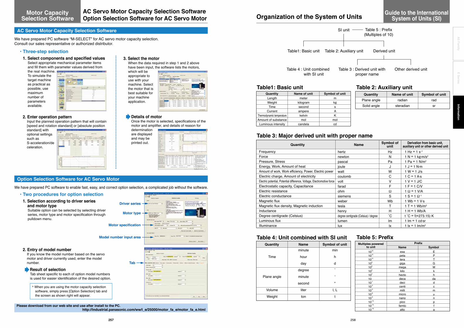
Details of motorOnce the motor is selected, specifications of the motor and amplifier, and details of reason for determination are displayed and may be printed out.
We have prepared PC software to enable fast, easy, and correct option selection, a complicated job without the software.
• Two procedures for option selection 1. Selection according to driver series and motor type
Suitable option can be selected by selecting driver series, motor type and motor specification through pulldown menu.
2. Entry of model numberIf you know the model number based on the servo motor and driver currently used, enter the model number.
Result of selectionTab sheet specific to each of option model numbers is used for easier identification of the desired option.
Driver series
Motor type
Tab
Model number input area
Motor specification
* When you are using the motor capacity selection software, simply press [Option Selection] tab and the screen as shown right will appear.
AC Servo Motor Capacity Selection SoftwareWe have prepared PC software “M-SELECT” for AC servo motor capacity selection. Consult our sales representative or authorized distributor.
• Three-step selection 1. Select components and specified values
Select appropriate mechanical parameter items and fill them with parameter values derived from the real machine. To simulate the target machine as practical as possible, use maximum number of parameters available.
3. Select the motorWhen the data required in step 1 and 2 above have been input, the software lists the motors, which will be appropriate to use with your machine. Select the motor that is best suitable for your machine application.
Option Selection Software for AC Servo Motor
2. Enter operation patternInput the planned operation pattern that will contain [speed and rotation standard] or [absolute position standard] with optional settings such as S-acceleration/deceleration.
Please download from our web site and use after install to the PC.http://industrial.panasonic.com/ww/i_e/25000/motor_fa_e/motor_fa_e.html
Note (1) Applicable to liquid pressure. Also applicable to atmospheric pressure of meteorological data, when “bar” is used in international standard.(2) Applicable to scale or indication of blood pressure manometers.(3) “˚C” can be substituted for “K”.
Quantity
LengthAcceleration
Frequency Revolving speed, Number of revolutions
WeightMass
Weight flow rateMass flow rateSpecific weight
Density Specific volume
LoadForce
Moment of forcePressure
Stress
Elastic modulus
Energy, Work
Work efficiency, Power
Viscosity Kinetic viscosity
Thermodynamic temperatureTemperature interval
Amount of heat Heat capacity
Specific heat, Specific heat capacityEntropy
Specific entropyInternal energy (Enthalpy)
Specific internal energy (Specific enthalpy)Heat flux
Heat flux densityThermal conductivity
Coefficient of thermal conductivity Intensity of magnetic field
Magnetic fluxMagnetic flux density
μ (micron)GalG
c/s, crpmkgf–kgf/s
–kgf/m3
–m3/kgfkgfkgfdynkgf-mkgf/cm2
at (Engineering atmospheric pressure)atm (Atmospheric pressure)
mH2O, mAqmmHg
Torrkgf/mm2
kgf/cm2
kgf/m2
kgf-mergkgf-m/s
PSPPStK
degcal
cal/˚Ccal/ (kgf •˚C)
cal/Kcal/ (kgf •K)
calcal/kgfcal/h
cal/ (h •m2)cal/ (h •m •˚C)cal/ (h •m2•˚C)
OeMx
Gs,G
μmm/s2
m/s2
Hzs–1 or min–1, r/min
–kg–kg/s
–kg/m3
m3/kgNNN
N・mPa, bar (1) or kgf/cm2
PaPaPa
Pa or mmHg (2)
PaPa or N/m2
Pa or N/m2
Pa or N/m2
J (joule)J
W (watt)W
Pa•smm2/s
K (kelvin)K (3)
JJ/K (3)
cal/ (kgf •K)(3)
J/KJ/(kg •K)
JJ/kgW
W/m2
W/ (m •K) (3)
W/ (m2•K) (3)
A/mWb (weber)
T (tesla)
•
1 μ = 1 μm (micrometer)1 Gal = 10–2 m/s2
1 G = 9.80665 m/s2
1 c/s = Hz1 rpm = 1 min–1
Same value
Same value
Same value
Same value1 kgf = 9.80665 N1 kgf = 9.80665 N1 dyn = 10–5 N1 kgf-m = 9.806 N •m1 kgf/cm2 = 9.80665 x 10⁴ Pa = 0.980665 bar1 at = 9.80665 x 10⁴ Pa1 atm = 1.01325 x 10⁵ Pa1 mH2O = 9.80665 x 10³ Pa1 mmHg = 133.322 Pa
1 kgf/mm2 = 9.80665 x 10⁶ Pa =9.80665 x 10⁶ N/m2
1 kgf/cm2 = 9.80665 x 10⁴ Pa = 9.80665 x 10⁴ N/m2
1 kgf/m2 = 9.80665 Pa = 9.80665 N/m2
1 kgf/cm2 = 9.80665 x 10⁴ N/m2
1 kgf •m = 9.80665 J1 erg = 10–7 J1 kgf-m/s = 9.80665 W1 PS = 0.7355 kW1 P = 0.1 Pa•s10–2 St = 1 mm2/s1 K = 1 K1 deg = 1 K1 cal = 4.18605 J1 cal/˚C = 4.18605 J/K1 cal/ (kgf •˚C) = 4.18605 J/ (kg •K)1 cal/K = 4.18605 J/K1 cal/ (kgf •K) = 4.18605 J/ (kg •K)1 cal = 4.18605 J1 cal/kgf = 4.18605 J/kg1 kcal/h = 1.16279 W1 kcal/ (h •m2) = 1.16279 W/m2
1 kcal/ (h •m •˚C) = 1.16279 W/ (m •K)1 kcal/ (h •m2•˚C) = 1.16279 W/ (m2•K)1 Oe = 103 / (4π) A/m1 Mx = 10–8 Wb1 Gs = 10–4 T
Symbol ofconventional unit
Symbol of SI unit andcompatible unit Conversion value
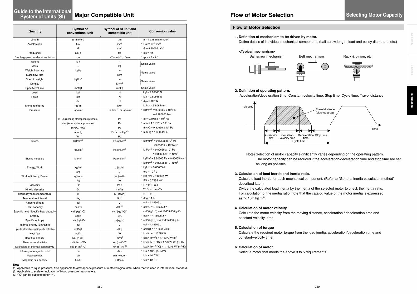
1. Definition of mechanism to be driven by motor. Define details of individual mechanical components (ball screw length, lead and pulley diameters, etc.)
<Typical mechanism> Ball screw mechanism Belt mechanism Rack & pinion, etc.
2. Definition of operating pattern. Acceleration/deceleration time, Constant-velocity time, Stop time, Cycle time, Travel distance
Note) Selection of motor capacity significantly varies depending on the operating pattern. The motor capacity can be reduced if the acceleration/deceleration time and stop time are set
as long as possible.
3. Calculation of load inertia and inertia ratio. Calculate load inertia for each mechanical component. (Refer to "General inertia calculation method"
described later.) Divide the calculated load inertia by the inertia of the selected motor to check the inertia ratio. For calculation of the inertia ratio, note that the catalog value of the motor inertia is expressed as "× 10–4 kg•m2".
4. Calculation of motor velocity Calculate the motor velocity from the moving distance, acceleration / deceleration time and
constant-velocity time.
5. Calculation of torque Calculate the required motor torque from the load inertia, acceleration/deceleration time and
constant-velocity time.
6. Calculation of motor Select a motor that meets the above 3 to 5 requirements.
Time
VelocityTravel distance (slashed area)
Stop timeDecelerationtime
Cycle time
Accelerationtime
Constant-velocity time
259 260
A5 Fam
ilyE Series
Information
Selecting Motor CapacityGuide to the International System of Units (SI) Major Compatible Unit Flow of Motor Selection
Flow of Motor Selection

1. Torque (1) Peak torque
Indicate the maximum torque that the motor requires during operation (mainly in acceleration and deceleration steps). The reference value is 80% or less of the maximum motor torque. If the torque is a negative value, a regenerative discharge resistor may be required.
(2) Traveling torque, Stop holding torque Indicates the torque that the motor requires for a long time. The reference value is 80% or less of the rated motor torque. If the torque is a negative value, a regenerative discharge resistor may be required.
Traveling torque calculation formula for each mechanism
Ball screw mechanism
Belt mechanism
(3) Effective torqueIndicates a root-mean-square value of the total torque required for running and stopping the motor per unit time. The reference value is approx. 80% or less of the rated motor torque.
2. Motor velocity Maximum velocity
Maximum velocity of motor in operation: The reference value is the rated velocity or lower value.When the motor runs at the maximum velocity, you must pay attention to the motor torque and temperature rise. For actual calculation of motor velocity, see "Example of motor selection" described later.
Tf=2π
P (μgW+F )
tc
WD
F
P
WF
Traveling torque
W : Weight [kg] P : Lead [m] F : External force [N]
: Mechanical efficiencyμ : Coefficient of frictiong : Acceleration of gravity 9.8[m/s2]
T f=2π
D (μgW+F )Traveling torque
W : Weight [kg] P : Pulley diameter [m] F : External force [N]
: Mechanical efficiencyμ : Coefficient of frictiong : Acceleration of gravity 9.8[m/s2]
Ta2 x ta + Tf2 x tb + Td2 x tdTrms =
Ta : Acceleration torque [N •m]Tf : Traveling torque [N •m]Td : Deceleration torque [N •m]
ta : Acceleration time [s]tb : Constant-velocity time [s]td : Deceleration time [s]
tc : Cycle time [s] (Run time + Stop time)
J = J1 + ( ) 2 J2
3. Inertia and inertia ratioInertia is like the force to retain the current moving condition. Inertia ratio is calculated by dividing load inertia by rotor inertia. Generally, for motors with 750 W or lower capacity, the inertia ratio should be “20” or less. For motors with 1000 W or higher capacity, the inertia ratio should be “10” or less. If you need quicker response, a lower inertia ratio is required. For example, when the motor takes several seconds in acceleration step, the inertia ratio can be further increased.
J =81 WD2 [kg •m2]
J =121 W (a2 + b2) [kg •m2]
J =81 W(D2 + d2) [kg •m2]
n2n1
J =41 WD2 [kg •m2]
W : Weight [kg]
D : Outer diameter [m]
W : Weight [kg] D : Outer diameter [m] d : Inner diameter [m]
J =81 WD2 + WS2 [kg •m2]
W : Weight [kg] D : Outer diameter [m] S : Distance [m]
J = JB + 4π 2
W • P2[kg •m2]
W : Weight [kg] P : LeadJB : J of ball screw
J =481 W(3D2 + 4L2) [kg •m2]
W : Weight [kg] D : Outer diameter [m] L : Length [m]
Shape
General inertia calculation method
Disk
J calculation formula Shape J calculation formula
W : Weight [kg]
a, b, c : Side length [m]
n1 : A rotational speed of a shaft [ r/min]n2 : A rotational speed of b shaft [ r/min]
J =31 WL2 [kg •m2]
[kg •m2]
W : Weight [kg]
L : Length [m]
W : Workpiece weight on conveyor [kg]
D : Drum diameter [m]
Inertia on shaft "a"
* Excluding drum J
Prism
Straight rod
Reduction gear
Conveyor
Hollow cylinder
Uniform rod
Separated rod
Ball screw
If weight (W [kg]) is unknown, calculate it with the following formula: Weight W[kg]=Density [kg/m3] x Volume V[m3] Density of each material Iron =7.9 x 10³ [kg/m3] Aluminum =2.8 x 10³ [kg/m3] Brass =8.5 x 10³ [kg/m3]
D
WD
P
WF
a b
cD
L/2L/2
aJ 1
J 2n2
n1
b
L
D
d
S
D
( )
261 262
A5 Fam
ilyE Series
Information
Description on the Items Related to Motor Selection
Description on the Items Related to Motor SelectionSelecting Motor Capacity

= 0.00001 + (1.24 × 0.022) / 8 + 10 × 0.022 / 4π 2
= 1.73 × 10⁻⁴ [kg •m 2]
21
21
JL = JC + JB = JC + BW × BD2 + 81
4π 2WA •BP2
1. Example of motor selection for driving ball screw mechanism Workpiece weight WA = 10 [kg] Ball screw length B L = 0.5 [m] Ball screw diameter BD = 0.02 [m] Ball screw lead BP = 0.02 [m] Ball screw efficiency B = 0.9 Travel distance 0.3[m] Coupling inertia Jc = 10 x 10–6 [kg •m2] (Use manufacturer-specified catalog value, or calculation value.)
2. Running pattern : Acceleration time ta = 0.1 [s] Constant-velocity time tb = 0.8 [s] Deceleration time td = 0.1 [s] Cycle time tc = 2 [s] Travel distance 0.3[m]
3. Ball screw weight
4. Load inertia
5. Provisional motor selection In case of MSME 200 W motor :
6. Calculation of inertia ratio
7. Calculation of maximum velocity (Vmax)
8. Calculation of motor velocity (N [r/min]) Ball screw lead per resolution: BP = 0.02 [m]
9. Calculation of torque
BW = × π × 2 × BL = 7.9 × 10³ × π ×
2 × 0.5
= 1.24 [kg]2
BD2
0.02
JL / JM = 1.73 x 10⁻⁴ / 0.14 x 10⁻⁴ Therefore, the inertia ratio is "12.3" (less than "30")(In case of MSME 100 W motor: JM = 0.051 x 10⁻⁴ Therefore, the inertia ratio is "33.9".)
×Acceleration time×Vmax+Constant-velocity time×Vmax+ ×Deceleration time×Vmax = Travel distance
21
21 × 0.1 × Vmax + 0.8 × Vmax + × 0.1 × Vmax = 0.3
0.9 × Vmax = 0.3 Vmax = 0.3 / 0.9 = 0.334 [m/s]
N = 0.334 / 0.02 = 16.7 [r/s] = 16.7 × 60 = 1002 [r/min] < 3000 [r/min] (Rated velocity of MSME 200W motor)
Traveling torque Tf = (μgWA + F) = (0.1×9.8×10+0)
= 0.035 [N •m] 2πB
BP2π x 0.9
0.02
Acceleration torque Ta = + Traveling torque
= + 0.035
= 0.196 + 0.035 = 0.231 [N •m]
Acceleration time [s] (JL + JM) × 2πN [ r /s]
0.1(1.73 × 10⁻⁴ + 0.14 × 10–4) × 2π × 16.7
Time
VelocityTravel distance (slashed area)
Stop timeDecelerationtime
Cycle time
Accelerationtime
Constant-velocity time
JM = 0.14 × 10⁻⁴ [kg •m 2]
10. Verification of maximum torque
11. Verification of effective torque
12. Judging from the inertia ratio calculated above, selection of 200 W motor is preferable, although the torque margin is significantly large.
Example of motor selection for timing belt mechanism 1.Mechanism Workpiece weight WA = 2[kg] (including belt) Pulley diameter PD = 0.05[m] Pulley weight WP = 0.5[kg] (Use manufacturer-specified catalog value, or calculation value.) Mechanical efficiency B = 0.8 Coupling inertia Jc = 0 (Direct connection to motor shaft) Belt mechanism inertia JB Pulley inertia JP
2. Running pattern Acceleration time ta = 0.1[s] Constant-velocity time tb = 0.8[s] Deceleration time td = 0.1[s] Cycle time tc = 2[s] Travel distance 1[m]
3. Load inertia JL = JC + JB + JP
4. Provisional motor selection In case of MSME 750 W motor :
5. Calculation of inertia ratio
Deceleration torque Td = – Traveling torque
= – 0.035
= 0.196 – 0.035 = 0.161 [N •m]
Deceleration time [s] (JL + JM) × 2πN [ r /s]
0.1(1.73 × 10⁻⁴ + 0.14 × 10–4) × 2π × 16.7
Acceleration torque = Ta = 0.231 [N •m] < 1.91 [N •m] (Maximum torque of MSME 200 W motor)
tc
Ta2 × ta + Tf2 × tb + Td2 × tdTrms =
20.2312 × 0.1 + 0.0352 × 0.8 + 0.1612 × 0.1 =
= 0.067 [N •m] < 0.64 [N •m] (Rated torque of MSME 200 W motor)
Time
VelocityTravel distance (slashed area)
Stop timeDecelerationtime
Cycle time
Accelerationtime
Constant-velocity time
= 0 + × 2 × 0.052 + × 0.5 × 0.052 × 2
= 0.00156 = 15.6 × 10⁻⁴ [kg •m 2]
= JC + WA × PD2 + WP × PD2 × 241
41
81
81
JM = 0.87 × 10⁻⁴ [kg •m 2]
JL / JM = 15.6 × 10⁻⁴ / 0.87 × 10⁻⁴ Therefore, the inertia ratio is "17.9" (less than "20")
263 264
A5 Fam
ilyE Series
Information
To Drive Ball Screw Mechanism
To Drive Ball Screw Mechanism
To Drive Ball Screw Mechanism Example of Motor Selection
Example of Motor Selection
Selecting Motor Capacity Selecting Motor Capacity

6. Calculation of maximum velocity (Vmax)
7. Calculation of motor velocity (N [r/min]) A single rotation of pulley :
8. Calculation of torque
Traveling torque
Acceleration torque
Deceleration torque
9. Verification of maximum torque
Acceleration torque
10. Verification of effective torque
11. Judging from the above calculation result, selection of MSME 750W motor is acceptable.
×Acceleration time×Vmax+Constant-velocity time×Vmax+ ×Deceleration time×Vmax=Travel distance
N = 1.111 / 0.157 = 7.08[r/s] = 7.08 × 60 = 424.8[r/min] < 3000[r/min] (Rated velocity of MSME 750 W motor)
21
21
× 0.1 × Vmax + 0.8 × Vmax + × 0.1 × Vmax = 121
Tf = (μgWA + F) = (0.1 × 9.8 × 3 + 0)2 × 0.80.05
2 PD
21
0.9 × Vmax = 1 Vmax = 1 / 0.9 = 1.111[m/s]
= 0.061[N •m]
Ta = + Traveling torque
Ta = 0.812[N •m] < 7.1[N •m] (Maximum torque of MSME 750 W motor)
Acceleration time[s](JL + JM) x 2πN [ r /s]
= + 0.061
= 0.751 + 0.061 = 0.812[N •m]0.1
(15.6 × 10⁻⁴ + 0.87 × 10–4) × 2π × 7.08
Td = – Traveling torqueDeceleration time[s](JL + JM) × 2πN [ r /s]
= – 0.061
= 0.751 – 0.061 = 0.69[N •m]0.1
(15.6 × 10⁻⁴ + 0.87 × 10–4) × 2π × 7.08
tcTa2 × ta + Tf2 × tb + Td2 × tdTrms =
20.8122 × 0.1 + 0.0612 × 0.8 + 0.692 × 0.1 =
= 0.241 [N •m] < 2.4 [N •m] (Rated torque of MSME 750 W motor)
π × PD = 0.157[m]ta td
t0 ts
FWA
Running pattern
time
velo
city
1
Request Sheet for Motor Selection
Request for motor selectionⅠ: Ball screw drive1. Driven mechanism and running data
2. Other data (Fill the details on specific mechanism and its configurations in the following blank.)
Company name :
Department/Section :
Name :
Address :
Tel :
Fax :
E-mail address:
1) Travel distance of the work load per one cycle ℓ1: mm
2) Cycle time to: s
(Fill in items 3) and 4) if required.)
3) Acceleration time ta: s
4) Deceleration time td: s
5) Stopping time ts: s
6) Max. velocity V: mm/s
7) External force F: N
8) Positioning accuracy of the work load ± mm
9) Total weight of the work load and the table WA: kg
10) Power supply voltage V
11) Diameter of the ball screw mm
12) Total length of the ball mm
13) Lead of the ball screw mm 14) Traveling direction(horizontal, vertical etc.)
266
A5 Fam
ilyE Series
Information
265
Example of Motor SelectionSelecting Motor Capacity

267 268
A5 Fam
ilyE Series
Information
ta tdt0 ts
F WA
D2(W2)
D1(W1)
WM
L1
Running pattern
time
velo
city 1
Request Sheet for Motor Selection
Request for motor selectionⅡ : Timing pulley + Ball screw drive1. Driven mechanism and running data
2. Other data (Fill the details on specific mechanism and its configurations in the following blank.)
Company name :
Department/Section :
Name :
Address :
Tel :
Fax :
E-mail address:
1) Travel distance of the work load per one cycle ℓ1: mm
2) Cycle time to: s
(Fill in items 3) and 4) if required.)
3) Acceleration time ta: s
4) Deceleration time td: s
5) Stopping time ts: s
6) Max. velocity V: mm/s
7) External force F: N
8) Positioning accuracy of the work load ± mm
9) Total weight of the work load and the table WA: kg
10) Power supply voltage V
11) Diameter of the ball screw mm
12) Total length of the ball screw mm
13) Lead of the ball screw mm
14) Traveling direction(horizontal, vertical etc.)
Motor side Ball screw side
15) Diameter of the pulley D1: mm D2: mm
16) Weight of the pulley W1: kg W2: kg
(or item 17) and 18))
17) Width of the pulley L1: mm
18) Material of the pulley
19) Weight of the belt WM: kg
ta tdt0 ts
FWA
W1
L1
D1
Running pattern
time
velo
city 1
Request Sheet for Motor Selection
Request for motor selectionⅢ : Belt drive1. Driven mechanism and running data
2. Other data (Fill the details on specific mechanism and its configurations in the following blank.)
Company name :
Department/Section :
Name :
Address :
Tel :
Fax :
E-mail address:
1) Travel distance of the work load per one cycle ℓ1: mm
2) Cycle time to: s
(Fill in items 3) and 4) if required.)
3) Acceleration time ta: s
4) Deceleration time td: s
5) Stopping time ts: s
6) Max. velocity V: mm/s
7) External force F: N
8) Positioning accuracy of the work load ± mm
9) Total weight of the work load WA: kg
10) Power supply voltage V
11) Weight of the belt WM: kg
12) Diameter of the driving pulley D1: mm
13) Total weight of the pulley W1: kg
(or item 14) and 15))
14) Width of the pulley L1: mm
15) Material of the pulley
16) Traveling direction(horizontal, vertical etc.)

269 270
A5 Fam
ilyE Series
Information
ta tdt0 ts
L1
L2
WM
WL
WA
D2(W2)
D3(W3)
D4(W4)
F
D1(W1)
Running pattern
time
velo
city 1
Request Sheet for Motor Selection
Request for motor selectionⅣ : Timing pulley + Belt drive1. Driven mechanism and running data
2. Other data (Fill the details on specific mechanism and its configurations in the following blank.)
Company name :
Department/Section :
Name :
Address :
Tel :
Fax :
E-mail address:
1) Travel distance of the work load per one cycle ℓ1: mm
2) Cycle time to: s
(Fill in items 3) and 4) if required.)
3) Acceleration time ta: s
4) Deceleration time td: s
5) Stopping time ts: s
6) Max. velocity V: mm/s
7) External force F: N
8) Positioning accuracy of the work load ± mm
9) Total weight of the work load and the table WA: kg
10) Power supply voltage V
11) Weight of motor side belt WM: kg
Motor side Belt side
12) Diameter of the pulley D1: mm D2: mm
13) Weight of the pulley W1: kg W2: kg
(or item 14) and 15))
14) Width of the belt L1: mm
15) Material of the pulley
Motor side Belt side
16) Diameter of the pulley D3: mm D4: mm
17) Weight of the pulley W3: kg W4: kg
(or item 18) and 19))
18) Width of the pulley L2: mm
19) Material of the pulley
20) Weight of the belt WM: kg
21) Traveling direction(horizontal, vertical etc.)
D1
b b
cc
a
a
WA
R1
ta tdt0 ts
d1
Running pattern
time
velo
city
Request Sheet for Motor Selection
Request for motor selectionⅤ : Turntable drive1. Driven mechanism and running data
2. Other data (Fill the details on specific mechanism and its configurations in the following blank.)
Company name :
Department/Section :
Name :
Address :
Tel :
Fax :
E-mail address:
1) Travel distance of the work load per one cycle d1: deg
2) Cycle time to: s
(Fill in items 3) and 4) if required.)
3) Acceleration time ta: s
4) Deceleration time td: s
5) Stopping time ts: s
6) Max. rotational speed of the table v: deg/s
(or) V: r/s
7) Positioning accuracy of the work load ± deg
8) Weight of one work load WA: kg
9) Driving radius of the center of gravity of the work R1: mm
10) Diameter of the table D1: mm
11) Mass of the table W1: kg
12) Diameter of the table support T1: mm
13) Power supply voltage V
Prism Cylinder
14) Dimensions of the work load a: mm a: mm
b: mm b: mm
c: mm c: mm
15) Number of work loads pcs

271 272
A5 Fam
ilyE Series
Information
Running pattern
time
velo
city
ta tdt0 ts
bb
cc
WA
D1
L1WM
D2(W2)
R1
D3(W3)
aa
d1
Request Sheet for Motor Selection
Request for motor selectionⅥ : Timing pulley + Turntable drive1. Driven mechanism and running data
2. Other data (Fill the details on specific mechanism and its configurations in the following blank.)
Company name :
Department/Section :
Name :
Address :
Tel :
Fax :
E-mail address:
1) Travel distance of the work load per one cycle d1: deg
2) Cycle time to: s
(Fill in items 3) and 4) if required.)
3) Acceleration time ta: s
4) Deceleration time td: s
5) Stopping time ts: s
6) Max. rotational speed of the table v: deg/s
(or) V: r/s
7) Positioning accuracy of the work load ± deg
8) Weight of one work load WA: kg
9) Driving radius of the center of gravity of the work R1: mm
10) Diameter of the table D1: mm
11) Mass of the table W1: kg
12) Diameter of the table support T1: mm
13) Power supply voltage V
(Prism) (Cylinder)
14) Dimension of the work load a: mm a: mm
b: mm b: mm
c: mm c: mm
15) Number of work loads pcs
Motor side Turntable side
16) Diameter of the pulley D2: mm D3: mm
17) Weight of the pulley W2: kg W3: kg
(or item 18) and 19))
18) Width of the pulley L1: mm
19) Material of the pulley
20) Weight of the belt WM: kg
Running pattern
time
velo
city
ta tdt0 ts
F
L1
D1(W1)
1
Request Sheet for Motor Selection
Request for motor selectionⅦ : Roller feed drive1. Driven mechanism and running data
2. Other data (Fill the details on specific mechanism and its configurations in the following blank.)
Company name :
Department/Section :
Name :
Address :
Tel :
Fax :
E-mail address:
1) Travel distance of the work load per one cycle ℓ1: mm
2) Cycle time to: s
(Fill in items 3) and 4) if required.)
3) Acceleration time ta: s
4) Deceleration time td: s
5) Stopping time ts: s
6) Max. velocity v: mm/s
7) External pulling force F: N
8) Positioning accuracy of the work load ± mm
9) Number of rollers pcs
10) Power supply voltage V
11) Diameter of the roller D1: mm
12) Mass of the roller W1: kg
(or item 13) and 14))
13) Width of the roller L1: mm
14) Material of the roller

274
A5 Fam
ilyE Series
Information
273
Connection Between Driver and Controller
CW limit sensorOrigin proximity sensor
CCW limit sensor
CW limit sensorOrigin proximity sensor
CCW limit sensor
GND +24 VDC24 V
Power supply
GND +24 VDC24 V
Power supply
Command pulse input 1
Command sign input 1
Command pulse input 2
Counter clear inputServo-ON input
Servo-Ready output
Servo-Alarm output
Positioning complete output
Alarm clear input
Z-phase output
Command sign input 2
Gain switching input
Inhibit negative direction travel input
Inhibit positive direction travel input
CW pulse command output
CCW pulse command output
Origin input (5 VDC)
Servo-ON outputDeviation counter reset output
External power supply input
Origin proximity input
Limit excess +
Limit excess −
CW pulse command output
CCW pulse command output
Origin input
Deviation counter reset output
External power supply input
Origin proximity input
A5Ⅱ, A5ⅡE, A5, A5E series
503456
2324
13,257
3029273198
35343736393841
FGPULS1PULS2SIGN1SIGN2OZ+OZ−GND
COM+CL
SRV-ONGAIN
A-CLRPOTNOT
S-RDY+S-RDY−ALM+ALM−INP+INP−
COM−
* Process of shield wire varies with equipment.
220 Ω
+24 VGND
* Pulse train interface exclusive for line driver
Pulse train interface exclusive for line driver. Use this interface when you use pulse command frequency between 500 kpps and 4 Mpps
* When connecting, please be sure to use twisted-pair cable.
* When connecting, please be sure to use twisted-pair cable.
FP7-AFP7PP02T/L(2-axes) AFP7PP04T/L(4-axes) Connection with the Panasonic devices SUNX.
Command pulse input 2
Counter clear inputServo-ON input
Servo-Ready output
Servo-Alarm output
Positioning complete output
Alarm clear input
Z-phase output
Command sign input 2
Gain switching input
Inhibit negative direction travel input
Inhibit positive direction travel input
44454647
PULSH1PULSH2SIGNH1SIGNH2
Command pulse input 1
Command sign input 1
FP7-AFP7PP02T/L(2-axes) AFP7PP04T/L(4-axes)(Panasonic devices SUNX)
220 Ω
4.7 kΩ
560 Ω
3.9 kΩ
3.6 kΩ
6.8 kΩ
4.7 kΩ
4.7 kΩ
4.7 kΩ
4.7 kΩ
4.7 kΩ
fromPLC I/O output
toPLC I/O input
A1B1A2B2A3A4B3B5A7B7B4A5
A6
B6A20B20
A10B10A11B11A12A13B12B14A16B16B13A14
A15
B15A20B20
1/3-axes 2/4-axes
A5Ⅱ, A5ⅡE, A5, A5E series503456
2324
13,257
3029273198
35343736393841
FGPULS1PULS2SIGN1SIGN2OZ+OZ−GND
COM+CL
SRV-ONGAIN
A-CLRPOTNOT
S-RDY+S-RDY−ALM+ALM−INP+INP−
COM−
* Process of shield wire varies with equipment.
220 Ω
FGFG
+24 VGND
* Pulse train interface exclusive for line driver
Pulse train interface exclusive for line driver. Use this interface when you use pulse command frequency between 500 kpps and 4 Mpps
FPG-PP12 AFPG432 Connection with the Panasonic devices SUNX.
44454647
PULSH1PULSH2SIGNH1SIGNH2
PLC
FPG-PP12 AFPG432(Panasonic devices SUNX)
220 Ω
4.7 kΩ
560 Ω
6.8 kΩ
4.7 kΩ
4.7 kΩ
4.7 kΩ
4.7 kΩ
4.7 kΩ
fromPLC I/O output
toPLC I/O input
to PLC I/O input
A1B1A2B2A4B3
A7B7B4A5
A19B19A20B20
PLC Driver
Driver
Connection BetweenDriver and Controller
A5 Family
Running pattern
time
velo
city
ta tdt0 ts
D3
W3
F
WA
1
Request Sheet for Motor Selection
Request for motor selectionⅧ : Driving with Rack & Pinion1. Driven mechanism and running data
2. Other data (Fill the details on specific mechanism and its configurations in the following blank.)
Company name :
Department/Section :
Name :
Address :
Tel :
Fax :
E-mail address:
1) Travel distance of the work load per one cycle ℓ1: mm
2) Cycle time to: s
(Fill in items 3) and 4) if required.)
3) Acceleration time ta: s
4) Deceleration time td: s
5) Stopping time ts: s
6) Max. velocity V: mm/s
7) External force F: N
8) Positioning accuracy of the work load ± mm
9) Total weight of the work load WA: kg
10) Power supply voltage V
11) Diameter of the pinion D3: mm
12) Mass of the pinion W3: kg
13) Traveling direction(horizontal, vertical, etc.)

275 276
A5 Fam
ilyE Series
Information
Connection Between Driver and Controller
DC24 V Power supply
GND +24 V
Command pulse input 2
Counter clear inputServo-ON input
Servo-Ready output
Servo-Alarm output
Positioning complete output
Alarm clear input
Z-phase output
Command sign input 2
Gain switching input
Inhibit negative direction travel input
Inhibit positive direction travel input
CW limit sensorOrigin proximity sensor
CCW limit sensor
CW limit sensorOrigin proximity sensor
CCW limit sensor
CW pulse command output
CCW pulse command output
Origin input
Deviation counter reset output
External power supply input
Origin proximity input
CW pulse command output
CCW pulse command output
Origin input
Deviation counter reset output
Origin proximity input
CCW limit excess input
CW limit excess input
FP2-PP2 AFP2430 Connection with the Panasonic devices SUNX.
FP2-PP2 AFP2430(Panasonic devices SUNX)
Driver
A5Ⅱ, A5ⅡE, A5, A5E series* Process of shield wire varies with equipment.
220 Ω
FPG-C32T Connection with the Panasonic devices SUNX.
FPG-C32T(Panasonic devices SUNX)
220 Ω
4.7 kΩ
4.7 kΩ
4.7 kΩ
4.7 kΩ
4.7 kΩ
4.7 kΩ
fromPLC I/O output
toPLC I/O input
Y0
Y1
X2COM+
Y2−
COMX3
X5
X6
○
○
* Process of shield wire varies with equipment.
FGFG
+24 VGND
fromPLC I/O output
toPLC I/O input
to PLC I/O input
A1B1A2B2A5B5
A6B6A7B7
A19B19A20B20
1.6 kΩ
220 Ω
5.6 kΩ
5.6 kΩ
3 kΩ
5.6 kΩ
2 kΩ
2 kΩ
5034561913257302927319835343736393841
FGPULS1PULS2SIGN1SIGN2
CZGNDGND
COM+CL
SRV-ONGAINA-CLRPOTNOT
S-RDY+S-RDY−ALM+ALM−INP+INP−
COM−
* When connecting, please be sure to use twisted-pair cable.
* When connecting, please be sure to use twisted-pair cable.
GND +24 VDC24 V
Power supply
Command pulse input 1
Command sign input 1
Command pulse input 2
Counter clear inputServo-ON input
Servo-Ready output
Servo-Alarm output
Positioning complete output
Alarm clear input
Z-phase output
Command sign input 2
Gain switching input
Inhibit negative direction travel input
Inhibit positive direction travel input
A5Ⅱ, A5ⅡE, A5, A5E series
5034562324
13,257302927319835343736393841
FGPULS1PULS2SIGN1SIGN2OZ+OZ−GND
COM+CL
SRV-ONGAINA-CLRPOTNOT
S-RDY+S-RDY−ALM+ALM−INP+INP−
COM−
220 Ω
* Pulse train interface exclusive for line driver
Pulse train interface exclusive for line driver. Use this interface when you use pulse command frequency between 500 kpps and 4 Mpps
44454647
PULSH1PULSH2SIGNH1SIGNH2
220 Ω
4.7 kΩ
4.7 kΩ
4.7 kΩ
4.7 kΩ
4.7 kΩ
4.7 kΩ
DriverPLC
PLC
DC24 V Power supply
GND +24 V
DC24 V Power supply
GND +24 V
CCW limit sensorOrigin proximity sensor
CW limit sensor
CCW limit sensorOrigin proximity sensor
CW limit sensor
Pulse output A
Pulse output B
Origin input
Deviation counter reset output
Contact point input COM
External power supply 24 VDC inputExternal power supply 24 VDC input (GND)
Negative direction limit input
Positive direction limit input
Encoder Z-phase output +Encoder Z-phase output –
F3YP22-0P/F3YP24-0P/F3YP28-0P Connection with the Yokogawa Electric Corp.
F3YP22-0P/F3YP24-0P/F3YP28-0P(Yokogawa Electric Corp.)
fromPLC I/O output
toPLC I/O input
13a14a11a12a15a16a17a
10a9a
8b8a
1a2a
3a
4a7.4 kΩ
7.4 kΩ
7.4 kΩ
240 Ω
* Process of shield wire varies with equipment.
+VGND
F3NC32-ON/F3NC34-ON Connection with the Yokogawa Electric Corp.
F3NC32-ON/F3NC34-ON(Yokogawa Electric Corp.)
fromPLC I/O output
toPLC I/O input
4a3a6a5a
19a20a17a
14a
1a1b
13a
9a
8a
7a7.4 kΩ
7.4 kΩ
7.4 kΩ
240 Ω
* Process of shield wire varies with equipment.
* When connecting, please be sure to use twisted-pair cable.
* When connecting, please be sure to use twisted-pair cable.
Command pulse input 1
Command sign input 1
Command pulse input 2
Counter clear inputServo-ON input
Servo-Ready output
Servo-Alarm output
Positioning complete output
Alarm clear input
Z-phase output
Command sign input 2
Gain switching input
Inhibit negative direction travel input
Inhibit positive direction travel input
A5Ⅱ, A5ⅡE, A5, A5E series503456
2324
13,257
3029273198
35343736393841
FGPULS1PULS2SIGN1SIGN2OZ+OZ−GND
COM+CL
SRV-ONGAIN
A-CLRPOTNOT
S-RDY+S-RDY−ALM+ALM−INP+INP−
COM−
220 Ω
* Pulse train interface exclusive for line driver
Pulse train interface exclusive for line driver. Use this interface when you use pulse command frequency between 500 kpps and 4 MppsIn this case, please be sure to connect the signal ground of the amplifier and controller.
44454647
PULSH1PULSH2SIGNH1SIGNH2
220 Ω
4.7 kΩ
4.7 kΩ
4.7 kΩ
4.7 kΩ
4.7 kΩ
4.7 kΩ
Driver
PLC
PLC
Pulse output GND
Pulse output A
Pulse output B
Origin input
Deviation counter reset output
Contact point input COM
External power supply 24 VDC input
Negative direction limit inputPositive direction limit input
Encoder Z-phase output +Encoder Z-phase output –
Pulse output GND
Connection BetweenDriver and Controller
A5 Family

277 278
A5 Fam
ilyE Series
Information
CCW limit sensorOrigin proximity sensor
CW limit sensor
CCW limit sensorOrigin proximity sensor
CW limit sensor
DC24 V Power supply
DC5 V Power supply
GND +24 VGND +5 V
CW pulse command output
CCW pulse command output
Origin line driver input
Power supply for output
Deviation counter reset output
Emergency stop input
Origin proximity input
CCW limit excess input
CW limit excess input
CW pulse command output
CCW pulse command output
Origin line driver input
Deviation counter reset output
24 V power supply for output
Emergency stop input
Origin proximity input
CCW limit over input
CW limit over input
5 V power supplyfor pulse output
CJ1W-NC113 Connection with the Omron Corp.
+VGND
CJ1W-NC133 Connection with the Omron Corp.
CJ1W-NC133(Omron Corp.)
* Process of shield wire varies with equipment.CJ1W-NC113(Omron Corp.)
1.6 kΩ
fromPLC I/O output
toPLC I/O input
A6
A8
A14A12A1A2A10
A20A16
A17
A19
A18
150 Ω
1.6 kΩ
1.6 kΩ
4.7 kΩ
4.7 kΩ
4.7 kΩ
4.7 kΩ
fromPLC I/O output
toPLC I/O input
A5A6A7A8A14A12A1A2A10
A20A16
A17
A19
A18A3A4
4.7 kΩ
4.7 kΩ
4.7 kΩ
4.7 kΩ
150 Ω
* Process of shield wire varies with equipment.
GND+V
+VGND
1.6 kΩ
* When connecting, please be sure to use twisted-pair cable.
* When connecting, please be sure to use twisted-pair cable.
Command pulse input 2
Counter clear inputServo-ON input
Servo-Ready output
Servo-Alarm output
Positioning complete output
Alarm clear input
Z-phase output
Command sign input 2
Gain switching input
Inhibit negative direction travel input
Inhibit positive direction travel input
A5Ⅱ, A5ⅡE, A5, A5E series5034562324
13,257302927319835343736393841
FGPULS1PULS2SIGN1SIGN2OZ+OZ−GND
COM+CL
SRV-ONGAINA-CLRPOTNOT
S-RDY+S-RDY−ALM+ALM−INP+INP−
COM−
220 Ω
220 Ω
4.7 kΩ
4.7 kΩ
4.7 kΩ
4.7 kΩ
4.7 kΩ
4.7 kΩ
Driver
Command pulse input 2
Counter clear inputServo-ON input
Servo-Ready output
Servo-Alarm output
Positioning complete output
Alarm clear input
Z-phase output
Command sign input 2
Gain switching input
Inhibit negative direction travel input
Inhibit positive direction travel input
A5Ⅱ, A5ⅡE, A5, A5E series5034562324
13,257302927319835343736393841
FGPULS1PULS2SIGN1SIGN2OZ+OZ−GND
COM+CL
SRV-ONGAINA-CLRPOTNOT
S-RDY+S-RDY−ALM+ALM−INP+INP−
COM−
220 Ω
220 Ω
4.7 kΩ
4.7 kΩ
4.7 kΩ
4.7 kΩ
4.7 kΩ
4.7 kΩ
DriverPLC
PLC
GND +24 VDC24 V
Power supply
CW limit sensorOrigin proximity sensor
CCW limit sensor
CW limit sensorOrigin proximity sensor
CCW limit sensor
CW pulse command output
CCW pulse command output
Zero point signal
Deviation counter clear
Common
Proximity signalUpper limitLower limit
Drive unit ready
Origin sensor inputX axis limit switch CWX axis limit switch CCW
X axis CW
X sxis deviation counter clear
X axis CCW
* Process of shield wire varies with equipment.
QD75D1 Connection with the Mitsubishi Electric Corp.
QD75D1(Mitsubishi Electric Corp.)
300 Ω
fromPLC I/O output
toPLC I/O input
151617189
10
13141211
67312
* Process of shield wire varies with equipment.
KV-5000/3000 Connection with the KEYENCE Corp.
KV-5000/3000(KEYENCE Corp.)
fromPLC I/O output
toPLC I/O input
134
141516
19
26
36
40
4.7 kΩ
4.7 kΩ
4.3 kΩ
4.7 kΩ
2 kΩ
2 kΩ
4.3 kΩ
4.3 kΩ
4.3 kΩ
1.2 kΩ
* When connecting, please be sure to use twisted-pair cable.
* When connecting, please be sure to use twisted-pair cable.
Command pulse input 1
Command sign input 1
Command pulse input 2
Counter clear inputServo-ON input
Servo-Ready output
Servo-Alarm output
Positioning complete output
Alarm clear input
Z-phase output
Command sign input 2
Gain switching input
Inhibit negative direction travel input
Inhibit positive direction travel input
A5Ⅱ, A5ⅡE, A5, A5E series503456
2324
13,257
3029273198
35343736393841
FGPULS1PULS2SIGN1SIGN2OZ+OZ−GND
COM+CL
SRV-ONGAIN
A-CLRPOTNOT
S-RDY+S-RDY−ALM+ALM−INP+INP−
COM−
220 Ω
* Pulse train interface exclusive for line driver
Pulse train interface exclusive for line driver. Use this interface when you use pulse command frequency between 500 kpps and 4 Mpps
44454647
PULSH1PULSH2SIGNH1SIGNH2
220 Ω
4.7 kΩ
4.7 kΩ
4.7 kΩ
4.7 kΩ
4.7 kΩ
4.7 kΩ
Driver
GND +24 VDC24 V
Power supply
GND +24 VDC24 V
Power supply
PLC
PLC
Connection Between Driver and ControllerConnection BetweenDriver and Controller
A5 Family

279 280
A5 Fam
ilyE Series
Information
Replacing Old Model Servo Driver with MINAS A5Ⅱ, A5 series
For easier replacement of old driver (MINAS X/XX/V series) with A5Ⅱ, A5 series, use the interface conversion connector.
Driver
36-pin36-pin
Oldmodel
Hostcontroller
Driver
50-pin36-pin 50-pin
Currentmodel
36-pin → 50-pinConversion cable
DV0P4120DV0P4121
〈36-pin → 50-pin〉 〈50-pin → 50-pin〉
Hostcontroller
Oldmodel
Hostcontroller
Driver
50-pin50-pin 50-pin
50-pin
Currentmodel
Hostcontroller
Driver
50-pin
50-pin → 50-pinConversion cable
DV0P4130DV0P4131DV0P4132
When selecting the cable, refer to the table below because the part number of the cable is specific to the control mode of the old model.
Old model Control mode Conversion cable part No. Conversion wiring table
X seriesXX series(36-pin)
Position/velocity control DV0P4120P.280
Torque control DV0P4121
V series(50-pin)
Position control DV0P4130P.281
Velocity control DV0P4131
Torque control DV0P4132 P.282
* For external dimensions, refer to P.197.
Conversion Wiring Table
Pin No. on Old Model
DV0P4120 DV0P4121
Pin No. on Current Model
Signal Name Symbol
Pin No. on Current Model
Signal Name Symbol
1 23 Z-phase output OZ+ 23 Z-phase output OZ+
2 24 Z-phase output OZ– 24 Z-phase output OZ–
3 13 Signal ground GND 13 Signal ground GND
4 19 Z-phase output CZ 19 Z-phase output CZ
5 4 Command pulse input 2 PULS2 4 Command pulse input 2 PULS2
6 3 Command pulse input 2 PULS1 3 Command pulse input 2 PULS1
7 6 Command pulse sign input 2 SIGN2 6 Command pulse sign input 2 SIGN2
8 5 Command pulse sign input 2 SIGN1 5 Command pulse sign input 2 SIGN1
9 33 Command pulse inhibition input INH 33 Command pulse inhibition input INH
10 26 Speed zero clamp input ZEROSPD 26 Speed zero clamp input ZEROSPD
11 7 Power supply for control signal (+) COM+ 7 Power supply for control signal (+) COM+
12 29 Servo-ON input SRV-ON 29 Servo-ON input SRV-ON
13 30 Deviation counter clear input CL 30 Deviation counter clear input CL
14 14 Speed command input SPR NC
15 15 Signal ground GND 15 Signal ground GND
16 43 Speed monitor output SP 43 Speed monitor output SP
17 25 Signal ground GND 25 Signal ground GND
18 50 Frame ground FG 50 Frame ground FG
19 21 A-phase output OA+ 21 A-phase output OA+
20 22 A-phase output OA- 22 A-phase output OA-
21 48 B-phase output OB+ 48 B-phase output OB+
22 49 B-phase output OB– 49 B-phase output OB–
23 NC NC
24 NC NC
25 39 Positionning complete output Speed arrival output
COIN+ AT-SPEED+ 39 Positionning complete output
Speed arrival output COIN+ AT-SPEED+
26 37 Servo-Alarm output ALM+ 37 Servo-Alarm output ALM+
27 35 Servo-Ready output S-RDY+ 35 Servo-Ready output S-RDY+
28
34 Positionning complete output (–) Speed arrival output (–)
COIN– AT-SPEED– 34 Positionning complete output (–)
Speed arrival output (–)COIN– AT-SPEED–
36 Servo-Alarm output (–) ALM– 36 Servo-Alarm output (–) ALM–
38 Servo-Ready output (–) S-RDY– 38 Servo-Ready output (–) S-RDY–
41 Power supply for control signal (–) COM– 41 Power supply for control signal (–) COM–
29 8 CW over-travel inhibit input CWL 8 CW over-travel inhibit input CWL
30 9 CCW over-travel inhibit input CCWL 9 CCW over-travel inhibit input CCWL
31 31 Alarm clear input A-CLR 31 Alarm clear input A-CLR
32 32 Control mode switching input C-MODE 32 Control mode switching input C-MODE
33 18 CW direction torque limit input CWTL 18 CW direction torque limit input CWTL
34 16 CCW direction torque limit input CCWTL 14 Torque command input TRQR
35 17 Signal ground GND 17 Signal ground GND
36 42 Torque monitor output IM 42 Torque monitor output IM
* “NC” is no connect.
Connection BetweenDriver and Controller
A5 Family

281 282
A5 Fam
ilyE Series
Information
Pin No. on Old Model
DV0P4130 DV0P4131
Pin No. on Current Model
Signal Name Symbol
Pin No. on Current Model
Signal Name Symbol
1 8 CW over-travel inhibit input CWL 8 CW over-travel inhibit input CWL2 9 CCW over-travel inhibit input CCWL 9 CCW over-travel inhibit input CCWL3 3 Command pulse input 2 PULS1 NC4 4 Command pulse input 2 PULS2 NC5 5 Command pulse sign input 2 SIGN1 NC6 6 Command pulse sign input 2 SIGN2 NC7 7 Power supply for control signal (+) COM+ 7 Power supply for control signal (+) COM+8 NC NC9 NC NC10 NC NC11 11 External brake release signal BRK-OFF+ 11 External brake release signal BRK-OFF+12 12 Zero-speed detection output signal ZSP 12 Zero-speed detection output signal ZSP13 13 Torque in-limit signal output TLC 13 Torque in-limit signal output TLC14 NC 14 Speed command input SPR15 15 Signal ground GND 15 Signal ground GND16 16 CCW direction torque limit input CCWTL 16 CCW direction torque limit input CCWTL17 17 Signal ground GND 17 Signal ground GND18 18 CW direction torque limit input CWTL 18 CW direction torque limit input CWTL19 19 Z-phase output CZ 19 Z-phase output CZ20 NC NC21 21 A-phase output OA+ 21 A-phase output OA+22 22 A-phase output OA- 22 A-phase output OA-23 23 Z-phase output OZ+ 23 Z-phase output OZ+24 24 Z-phase output OZ- 24 Z-phase output OZ-25 50 Frame ground FG 50 Frame ground FG26 26 Speed zero clamp input ZEROSPD 26 Speed zero clamp input ZEROSPD27 27 Gain switching input GAIN 27 Gain switching input GAIN28 NC 33 Selection 1 input of internal command speed INTSPD129 29 Servo-ON input SRV-ON 29 Servo-ON input SRV-ON30 30 Deviation counter clear input CL NC31 31 Alarm clear input A-CLR 31 Alarm clear input A-CLR32 32 Control mode switching input C-MODE 32 Control mode switching input C-MODE33 33 Command pulse inhibition input INH NC34 NC NC35 35 Servo-Ready output S-RDY+ 35 Servo-Ready output S-RDY+36 NC NC37 37 Servo-Alarm output ALM+ 37 Servo-Alarm output ALM+38 NC NC39 39 Positionning complete output COIN+ 39 Speed arrival output AT-SPEED+40 40 Torque in-limit signal output TLC 40 Torque in-limit signal output TLC
41
10 External brake release signal (–) BRK-OFF– 10 External brake release signal (–) BRK-OFF–34 Positionning complete output (–) COIN– 34 Speed arrival output (–) AT-SPEED–36 Servo-Alarm output (–) ALM– 36 Servo-Alarm output (–) ALM–38 Servo-Ready output (–) S-RDY– 38 Servo-Ready output (–) S-RDY–41 Power supply for control signal (–) COM– 41 Power supply for control signal (–) COM–
42 42 Torque monitor output IM 42 Torque monitor output IM43 43 Speed monitor output SP 43 Speed monitor output SP44 25 Signal ground GND 25 Signal ground GND45 25 Signal ground GND 25 Signal ground GND46 25 Signal ground GND 25 Signal ground GND47 NC NC48 48 B-phase output OB+ 48 B-phase output OB+49 49 B-phase output OB– 49 B-phase output OB–50 50 Frame ground FG 50 Frame ground FG
* “NC” is no connect.
Pin No. on Old Model
DV0P4132
Pin No. on Current Model
Signal Name Symbol
1 8 CW over-travel inhibit input CWL2 9 CCW over-travel inhibit input CCWL3 NC4 NC5 NC6 NC7 7 Power supply for control signal (+) COM+8 NC9 NC10 NC11 11 External brake release signal BRK-OFF+12 12 Zero-speed detection output signal ZSP13 13 Torque in-limit signal output TLC14 NC15 15 Signal ground GND16 16 Torque command input TRQR17 17 Signal ground GND18 18 CW direction torque limit input CWTL19 19 Z-phase output CZ20 NC21 21 A-phase output OA+22 22 A-phase output OA-23 23 Z-phase output OZ+24 24 Z-phase output OZ-25 50 Frame ground FG26 26 Speed zero clamp input ZEROSPD27 27 Gain switching input GAIN28 NC29 29 Servo-ON input SRV-ON30 NC31 31 Alarm clear input A-CLR32 32 Control mode switching input C-MODE33 NC34 NC35 35 Servo-Ready output S-RDY+36 NC37 37 Servo-Alarm output ALM+38 NC39 39 Speed arrival output AT-SPEED+40 40 Torque in-limit signal output TLC
41
10 External brake release signal (–) BRK-OFF–34 Speed arrival output (–) AT-SPEED–36 Servo-Alarm output (–) ALM–38 Servo-Ready output (–) S-RDY–41 Power supply for control signal (–) COM–
42 42 Torque monitor output IM43 43 Speed monitor output SP44 25 Signal ground GND45 25 Signal ground GND46 25 Signal ground GND47 NC48 48 B-phase output OB+49 49 B-phase output OB–50 50 Frame ground FG
* “NC” is no connect.
Connection BetweenDriver and Controller
A5 Family Replacing Old Model Servo Driver with MINAS A5Ⅱ, A5 series
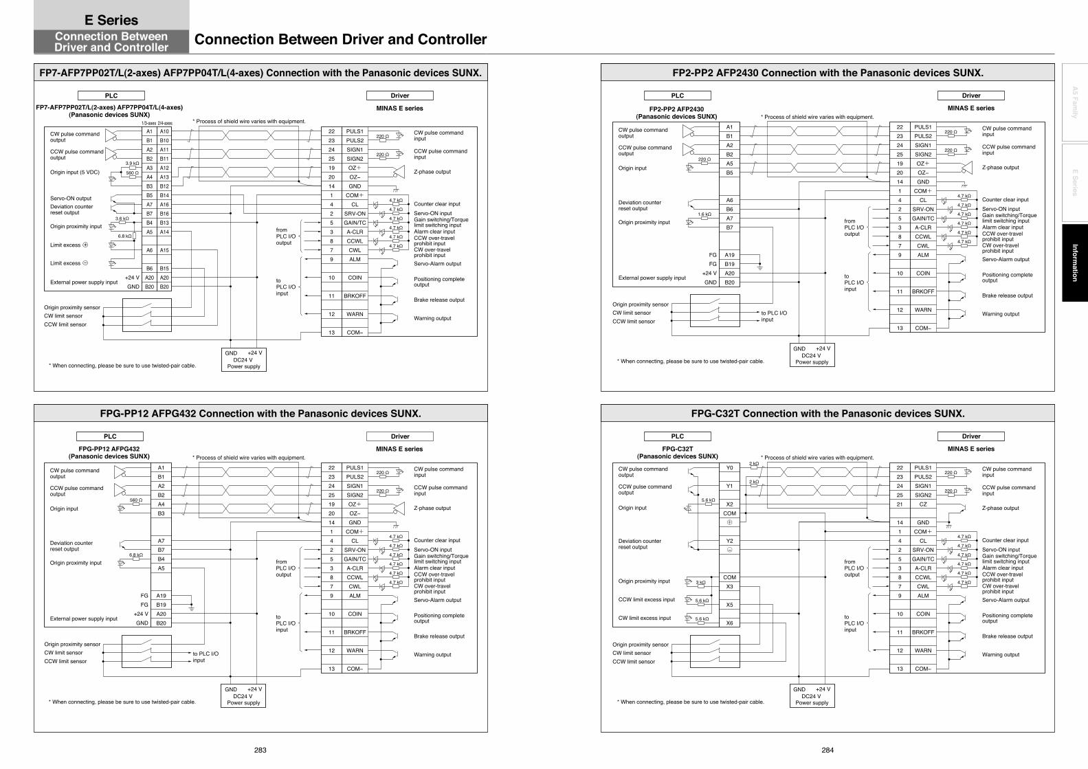
283 284
A5 Fam
ilyE Series
Information
FP2-PP2 AFP2430(Panasonic devices SUNX)
FPG-C32T(Panasonic devices SUNX)
toPLC I/O input
220 Ω
220 Ω
4.7 kΩ
4.7 kΩ
4.7 kΩ
4.7 kΩ
4.7 kΩ
4.7 kΩ
2223242521
1414253879
10
11
12
13
PULS1PULS2SIGN1SIGN2
CZ
GNDCOM+
CLSRV-ONGAIN/TCA-CLRCCWLCWLALM
COIN
BRKOFF
WARN
COM−
toPLC I/O input
* Process of shield wire varies with equipment.
FGFG
+24 VGND
fromPLC I/O output
to PLC I/O input
A1B1A2B2A5B5
A6B6A7B7
A19B19A20B20
1.6 kΩ
220 Ω
* Process of shield wire varies with equipment.
fromPLC I/O output
Y0
Y1
X2COM+
Y2−
COMX3
X5
X6
○
○
5.6 kΩ
5.6 kΩ
3 kΩ
5.6 kΩ
2 kΩ
2 kΩ
* When connecting, please be sure to use twisted-pair cable.
* When connecting, please be sure to use twisted-pair cable.
FP2-PP2 AFP2430 Connection with the Panasonic devices SUNX.
FPG-C32T Connection with the Panasonic devices SUNX.
MINAS E series
220 Ω
220 Ω
4.7 kΩ
4.7 kΩ
4.7 kΩ
4.7 kΩ
4.7 kΩ
4.7 kΩ
2223242519201414253879
10
11
12
13
PULS1PULS2SIGN1SIGN2OZ+OZ−GND
COM+CL
SRV-ONGAIN/TCA-CLRCCWLCWLALM
COIN
BRKOFF
WARN
COM−
Warning output
Brake release output
CW pulse command input
Counter clear inputServo-ON input
Servo-Alarm output
Positioning complete output
Alarm clear input
Z-phase output
CCW pulse command input
CW over-travel prohibit input
CCW over-travel prohibit input
Driver
MINAS E series
Driver
Gain switching/Torque limit switching input
Warning output
Brake release output
CW pulse command input
Counter clear inputServo-ON input
Servo-Alarm output
Positioning complete output
Alarm clear input
Z-phase output
CCW pulse command input
CW over-travel prohibit input
CCW over-travel prohibit input
Gain switching/Torque limit switching input
DC24 V Power supply
GND +24 V
CW limit sensorOrigin proximity sensor
CCW limit sensor
CW limit sensorOrigin proximity sensor
CCW limit sensor
CW pulse command output
CCW pulse command output
Origin input
Deviation counter reset output
Origin proximity input
CCW limit excess input
CW limit excess input
CW pulse command output
CCW pulse command output
Origin input
Deviation counter reset output
External power supply input
Origin proximity input
GND +24 VDC24 V
Power supply
PLC
PLC
MINAS E series
PLC
FPG-PP12 AFPG432(Panasonic devices SUNX)
MINAS E series* Process of shield wire varies with equipment.
FGFG
+24 VGND
560 Ω
6.8 kΩfromPLC I/O output
to PLC I/O input
A1B1A2B2A4B3
A7B7B4A5
A19B19A20B20
* Process of shield wire varies with equipment.
220 Ω
220 Ω
4.7 kΩ
4.7 kΩ
4.7 kΩ
4.7 kΩ
4.7 kΩ
4.7 kΩ
fromPLC I/O output
toPLC I/O input
2223242519201414253879
10
11
12
13
PULS1PULS2SIGN1SIGN2OZ+OZ−GND
COM+CL
SRV-ONGAIN/TCA-CLRCCWLCWLALM
COIN
BRKOFF
WARN
COM−
toPLC I/O input
+24 VGND
FP7-AFP7PP02T/L(2-axes) AFP7PP04T/L(4-axes)(Panasonic devices SUNX)
3.6 kΩ
A1B1A2B2A3A4B3B5A7B7B4A5
A6
B6A20B20
A10B10A11B11A12A13B12B14A16B16B13A14
A15
B15A20B20
1/3-axes 2/4-axes
* When connecting, please be sure to use twisted-pair cable.
* When connecting, please be sure to use twisted-pair cable.
FP7-AFP7PP02T/L(2-axes) AFP7PP04T/L(4-axes) Connection with the Panasonic devices SUNX.
FPG-PP12 AFPG432 Connection with the Panasonic devices SUNX.
6.8 kΩ
560 Ω
3.9 kΩ
Warning output
Brake release output
CW limit sensorOrigin proximity sensor
CCW limit sensor
CW limit sensorOrigin proximity sensor
CCW limit sensor
GND +24 VDC24 V
Power supply
GND +24 VDC24 V
Power supply
CW pulse command input
Counter clear inputServo-ON input
Servo-Alarm output
Positioning complete output
Alarm clear input
Z-phase output
CCW pulse command input
CW over-travel prohibit input
CCW over-travel prohibit inputLimit excess +
Limit excess −
CW pulse command output
CCW pulse command output
Origin input (5 VDC)
Servo-ON outputDeviation counter reset output
External power supply input
Origin proximity input
CW pulse command output
CCW pulse command output
Origin input
Deviation counter reset output
External power supply input
Origin proximity input
Driver
DriverPLC
Gain switching/Torque limit switching input
220 Ω
220 Ω
4.7 kΩ
4.7 kΩ
4.7 kΩ
4.7 kΩ
4.7 kΩ
4.7 kΩ
2223242519201414253879
10
11
12
13
PULS1PULS2SIGN1SIGN2OZ+OZ−GND
COM+CL
SRV-ONGAIN/TCA-CLRCCWLCWLALM
COIN
BRKOFF
WARN
COM−
Warning output
Brake release output
CW pulse command input
Counter clear inputServo-ON input
Servo-Alarm output
Positioning complete output
Alarm clear input
Z-phase output
CCW pulse command input
CW over-travel prohibit input
CCW over-travel prohibit input
Gain switching/Torque limit switching input
Connection Between Driver and ControllerConnection BetweenDriver and Controller
E Series

285 286
A5 Fam
ilyE Series
Information
PLC
CJ1W-NC113(Omron Corp.)
CJ1W-NC133(Omron Corp.)
+VGND
CWパルス指令出力
CCWパルス指令出力
原点ラインドライバ入力
出力用電源
偏差カウンタリセット出力
非常停止入力
原点近傍入力
CCWリミットオーバ入力
CWリミットオーバ入力
* Process of shield wire varies with equipment.
1.6 kΩ
fromPLC I/O output
A6
A8
A14A12A1A2
A10
A20A16
A17
A19
A18
150 Ω
1.6 kΩ
1.6 kΩ
4.7 kΩ
4.7 kΩ
4.7 kΩ
4.7 kΩ
fromPLC I/O output
A5A6A7A8
A14A12A1A2
A10
A20A16
A17
A19
A18A3A4
4.7 kΩ
4.7 kΩ
4.7 kΩ
4.7 kΩ
150 Ω
* Process of shield wire varies with equipment.
GND+V
+VGND
1.6 kΩ
toPLC I/O input
toPLC I/O input
* When connecting, please be sure to use twisted-pair cable.
* When connecting, please be sure to use twisted-pair cable.
CJ1W-NC113 Connection with the Omron Corp.
CJ1W-NC133 Connection with the Omron Corp.
CCW limit sensorOrigin proximity sensor
CW limit sensor
CCW limit sensorOrigin proximity sensor
CW limit sensor
DC24 V Power supply
DC5 V Power supply
GND +24 VGND +5 V
CW pulse command output
CCW pulse command output
Origin line driver input
Power supply for output
Deviation counter reset output
Emergency stop input
Origin proximity input
CCW limit excess input
CW limit excess input
CW pulse command output
CCW pulse command output
Origin line driver input
Deviation counter reset output
24 V power supply for output
Emergency stop input
Origin proximity input
CCW limit over input
CW limit over input
5 V power supplyfor pulse output
GND +24 VDC24 V
Power supply
MINAS E series
220 Ω
220 Ω
4.7 kΩ
4.7 kΩ
4.7 kΩ
4.7 kΩ
4.7 kΩ
4.7 kΩ
2223242519201414253879
10
11
12
13
PULS1PULS2SIGN1SIGN2OZ+OZ−GND
COM+CL
SRV-ONGAIN/TCA-CLRCCWLCWLALM
COIN
BRKOFF
WARN
COM−
Warning output
Brake release output
CW pulse command input
Counter clear inputServo-ON input
Servo-Alarm output
Positioning complete output
Alarm clear input
Z-phase output
CCW pulse command input
CW over-travel prohibit input
CCW over-travel prohibit input
Driver
Gain switching/Torque limit switching input
PLC
MINAS E series
MINAS E series
fromPLC I/O output
* Process of shield wire varies with equipment.
fromPLC I/O output
* Process of shield wire varies with equipment.
toPLC I/O input
toPLC I/O input
13a14a11a12a15a16a17a
10a9a
8b8a
1a2a
3a
4a7.4 kΩ
7.4 kΩ
7.4 kΩ
240 Ω
+VGND
4a3a6a5a19a20a17a
14a
1a1b
13a
9a
8a
7a7.4 kΩ
7.4 kΩ
7.4 kΩ
240 Ω
* When connecting, please be sure to use twisted-pair cable.
* When connecting, please be sure to use twisted-pair cable.
F3YP22-0P/F3YP24-0P/F3YP28-0P Connection with the Yokogawa Electric Corp.
F3NC32-ON/F3NC34-ON Connection with the Yokogawa Electric Corp.
DC24 V Power supply
GND +24 V
DC24 V Power supply
GND +24 V
CCW limit sensorOrigin proximity sensor
CW limit sensor
CCW limit sensorOrigin proximity sensor
CW limit sensor
Pulse output A
Pulse output B
Origin input
Deviation counter reset output
Contact point input COM
External power supply 24 VDC inputExternal power supply 24 VDC input (GND)
Negative direction limit input
Positive direction limit input
Encoder Z-phase output +Encoder Z-phase output –Pulse output GND
Pulse output A
Pulse output B
Origin input
Deviation counter reset output
Contact point input COM
External power supply 24 VDC input
Negative direction limit inputPositive direction limit input
Encoder Z-phase output +Encoder Z-phase output –
Pulse output GND
F3YP22-0P/F3YP24-0P/F3YP28-0P(Yokogawa Electric Corp.)
F3NC32-ON/F3NC34-ON(Yokogawa Electric Corp.)
220 Ω
220 Ω
4.7 kΩ
4.7 kΩ
4.7 kΩ
4.7 kΩ
4.7 kΩ
4.7 kΩ
2223242519201414253879
10
11
12
13
PULS1PULS2SIGN1SIGN2OZ+OZ−GND
COM+CL
SRV-ONGAIN/TCA-CLRCCWLCWLALM
COIN
BRKOFF
WARN
COM−
Warning output
Brake release output
CW pulse command input
Counter clear inputServo-ON input
Servo-Alarm output
Positioning complete output
Alarm clear input
Z-phase output
CCW pulse command input
CW over-travel prohibit input
CCW over-travel prohibit input
Gain switching/Torque limit switching input
220 Ω
220 Ω
4.7 kΩ
4.7 kΩ
4.7 kΩ
4.7 kΩ
4.7 kΩ
4.7 kΩ
2223242519201414253879
10
11
12
13
PULS1PULS2SIGN1SIGN2OZ+OZ−GND
COM+CL
SRV-ONGAIN/TCA-CLRCCWLCWLALM
COIN
BRKOFF
WARN
COM−
Warning output
Brake release output
CW pulse command input
Counter clear inputServo-ON input
Servo-Alarm output
Positioning complete output
Alarm clear input
Z-phase output
CCW pulse command input
CW over-travel prohibit input
CCW over-travel prohibit input
Gain switching/Torque limit switching input
Driver
Driver
PLC
PLC
Connection Between Driver and ControllerConnection BetweenDriver and Controller
E Series

288
A5 Fam
ilyE Series
Information
287
DV0PPart No. Title Page
DV0PPart No. Title Page
DV0PM20044 Connector for Power Supply Input Connection (E-frame) 200
DV0PM20045 Connector for Regenerative Resistor (E-frame 200 V/400 V common) 201
DV0PM20046 Connector for Motor Connection (E-frame 200 V/400 V common) 201
DV0PM20047 Reactor 209DV0PM20048 External Regenerative Resistor: 120 Ω 240 W 210DV0PM20049 External Regenerative Resistor: 80 Ω 450 W 210DV0PM20050 Surge absorber (3-phase) 253
DV0PM20051 Connector for Power Supply Input Connection (D-frame 400 V) 200
DV0PM20052 Connector for Power Supply Input Connection (E-frame 400 V) 200
DV0PM20053 Connector for Control Power Supply Input Connection (D,E-frame 400 V) 201
DV0PM20054 Connector for Motor Connection (D-frame 400V ) 201
DV0PM20055 Connector for Regenerative Resistor (D-frame 400 V) 201
DV0PM20056 Connector Kit for Motor/Encoder Connection 206DV0PM20057 Connector Kit for Motor/Encoder Connection 206DV0PM20058 External Regenerative Resistor: 3.3 Ω 780 W 210DV0PM20059 External Regenerative Resistor:13.3 Ω 1140 W 210
MADHTPart No. Title Page
MADHT1105 A5 series Driver: A-frame 29,42MADHT1105E A5E series Driver: A-frame 31,42MADHT1107 A5 series Driver: A-frame 29,42MADHT1107E A5E series Driver: A-frame 31,42MADHT1505 A5 series Driver: A-frame 29,42MADHT1505E A5E series Driver: A-frame 31,42MADHT1507 A5 series Driver: A-frame 29,42MADHT1507E A5E series Driver: A-frame 31,42
MADKTPart No. Title Page
MADKT1105 A5Ⅱ series Driver: A-frame 29,42MADKT1105E A5ⅡE series Driver: A-frame 31,42MADKT1107 A5Ⅱ series Driver: A-frame 29,42MADKT1107E A5ⅡE series Driver: A-frame 31,42MADKT1505 A5Ⅱ series Driver: A-frame 29,42MADKT1505E A5ⅡE series Driver: A-frame 31,42MADKT1507 A5Ⅱ series Driver: A-frame 29,42MADKT1507E A5ⅡE series Driver: A-frame 31,42
MBDHTPart No. Title Page
MBDHT2110 A5 series Driver: B-frame 29,42MBDHT2110E A5E series Driver: B-frame 31,42MBDHT2510 A5 series Driver: B-frame 29,42MBDHT2510E A5E series Driver: B-frame 31,42
MBDKTPart No. Title Page
MBDKT2110 A5Ⅱ series Driver: B-frame 29,42MBDKT2110E A5ⅡE series Driver: B-frame 31,42MBDKT2510 A5Ⅱ series Driver: B-frame 29,42MBDKT2510E A5ⅡE series Driver: B-frame 31,42
MCDHTPart No. Title Page
MCDHT3120 A5 series Driver: C-frame 29,43MCDHT3120E A5E series Driver: C-frame 31,43MCDHT3520 A5 series Driver: C-frame 29,43MCDHT3520E A5E series Driver: C-frame 31,43
MCDKTPart No. Title Page
MCDKT3120 A5Ⅱ series Driver: C-frame 29,43MCDKT3120E A5ⅡE series Driver: C-frame 31,43
DV0P0770 Connector kit for external peripheral equipment 240DV0P0800 Interface cable 241DV0P1450 Surge absorber (3-phase) 253,256DV0P1460 Noise Filter for Signal Lines 254,256DV0P1960 Communication cable 241DV0P220 Reactor 209DV0P221 Reactor 209DV0P222 Reactor 209DV0P223 Reactor 209DV0P224 Reactor 209DV0P225 Reactor 209DV0P227 Reactor 209DV0P228 Reactor 209DV0P2870 Connector kit for power supply connection 239DV0P2890 External regenerative resistor 242DV0P2891 External regenerative resistor 242DV0P2990 Battery For Absolute Encoder 207DV0P3410 Noise Filter 251DV0P3670 Connector kit for motor/encoder connection 239DV0P3680 Technical reference Japanese —DV0P3700 Technical reference English —DV0P37300 Cable set (3 m) 238DV0P3811 DIN rail mounting unit 242DV0P39200 Cable set (5 m) 238DV0P4120 Interface conversion cable 197DV0P4121 Interface conversion cable 197DV0P4130 Interface conversion cable 197DV0P4131 Interface conversion cable 197DV0P4132 Interface conversion cable 197DV0P4160 Noise filter 256DV0P4170 Noise Filter 250DV0P4190 Surge absorber (Single phase) 253,256DV0P4220 Noise Filter 250DV0P4280 External Regenerative Resistor: 50 Ω 25 W 210DV0P4281 External Regenerative Resistor: 100 Ω 25 W 210DV0P4282 External Regenerative Resistor: 25 Ω 50 W 210DV0P4283 External Regenerative Resistor: 50 Ω 50 W 210DV0P4284 External Regenerative Resistor: 30 Ω100 W 210DV0P4285 External Regenerative Resistor: 20 Ω130 W 210DV0P4290 Connector Kit for Motor/Encoder Connection 202DV0P4310 Connector Kit for Motor/Encoder Connection 204DV0P4320 Connector Kit for Motor/Encoder Connection 204DV0P4330 Connector Kit for Motor/Encoder Connection 205DV0P4340 Connector Kit for Motor/Encoder Connection 205DV0P4350 Interface Connector 198DV0P4360 Interface cable 197DV0P4380 Connector Kit for Motor/Encoder Connection 202DV0P4420 Console 241DV0P4430 Battery Box 207
DV0P4460 Setup support software “PANATERM” for MINAS series AC servo motor & Driver 236
DV0PM20010 Connector Kit: Encoder 199DV0PM20024 Connector Kit: RS485, 232 198DV0PM20025 Connector Kit: Safety 198DV0PM20026 Connector Kit: External Scale 199DV0PM20027 Mounting bracket: A-frame 208DV0PM20028 Mounting bracket: B-frame 208DV0PM20029 Mounting bracket: C-frame 208DV0PM20030 Mounting bracket: D-frame 208DV0PM20031 Connector Kit: Analog Monitor Signal 199
DV0PM20032 Connector for Power Supply Input Connection (A to D-frame (Single row type)) 200
DV0PM20033 Connector for Power Supply Input Connection (A to D-frame (Double row type)) 200
DV0PM20034 Connector for Motor Connection (A to D-frame) 201DV0PM20035 Connector Kit for Motor/Encoder Connection 203DV0PM20036 Connector Kit for Motor/Encoder Connection 203DV0PM20037 Connector Kit for Motor/Encoder Connection 204DV0PM20038 Connector Kit for Motor/Encoder Connection 204DV0PM20039 Connector Kit for Motor/Encoder Connection 205DV0PM20040 Connector Kit for Motor/Brake Connection 206DV0PM20042 Noise Filter 250DV0PM20043 Noise Filter 250
QD75D1(Mitsubishi Electric Corp.) * Process of shield wire varies with equipment.
300 Ω
fromPLC I/O output
15161718910
13141211
67312
4.7 kΩ
4.7 kΩ
4.7 kΩ
4.7 kΩ
toPLC I/O input
* When connecting, please be sure to use twisted-pair cable.
QD75D1 Connection with the Mitsubishi Electric Corp.
220 Ω
220 Ω
4.7 kΩ
4.7 kΩ
4.7 kΩ
4.7 kΩ
4.7 kΩ
4.7 kΩ
2223242519201414253879
10
11
12
13
PULS1PULS2SIGN1SIGN2OZ+OZ−GND
COM+CL
SRV-ONGAIN/TCA-CLRCCWLCWLALM
COIN
BRKOFF
WARN
COM−
Warning output
Brake release output
CW pulse command input
Counter clear inputServo-ON input
Servo-Alarm output
Positioning complete output
Alarm clear input
Z-phase output
CCW pulse command input
CW over-travel prohibit input
CCW over-travel prohibit input
Gain switching/Torque limit switching input
MINAS E series
Driver
CW limit sensorOrigin proximity sensor
CCW limit sensor
CW pulse command output
CCW pulse command output
Zero point signal
Deviation counter clear
Common
Proximity signalUpper limitLower limit
Drive unit ready
GND +24 VDC24 V
Power supply
PLC
Index(Alphabetical Order)Connection Between Driver and ControllerConnection Between
Driver and Controller
E Series