information – charge line · 2017-10-18 · information – charge line 6.0 charging – charge...
TRANSCRIPT

Info
rm
ation –
Charge L
ine
6.0
Charging – Charge Line
HAUG charging systems are intended for the contact-free application of electrostatic charges. These systems are used whenever different materials need to be fixed to one another electrostatically. At least one of these materials must be insulating. The electrostatic fixation is intended to support downstream processes such as the film overlap in packaging machines. HAUG charging machines can be used, among others, in the following applications:
for fixing and positioning films and foils, paper an cardboard, e.g. on steel sheets, glass panels, wood panels or similar
for fixing films and foils on packaging machines / film welding machines
for fixing films and foils on turret film winders, for fixing the wound film against telescoping and glue-less commencement of the film winding process on cardboard tubes
HAUG charging generators are direct voltage generators with different, adjustable output voltages between 0 and 40kV .DC
All charging generators are available with positive and negative polarity. Depending on the intented application, three different categories of generators can be supplied: the AG series, the TR series, and the AGW/HW series. The matching electrodes and triodes are available in customized lengths. The distance to the surface to be charged is between 10 – 30 mm (triode).
Note: We strongly recommend discharging the surfaces using a HAUG ionizing system before fixing the materials. A suitable counter-electrode is required to charge the different materials. If the counter-electrode is not provided by a metal machine part, it must be created by adding an ionizing bar, for example (refer to application technology 8.20).
•
•
•
10
–30
mm
Resistance-coupled charging
1 positive or negative voltage
2 electrical field
3 insulator (e.g. foil)
4 counter-electrode(e.g. earthed metal plate)
5 intake electrodes
1 positive or negative voltage
2 electrical field
3 insulator (e.g. foil)
4 counter-electrode(e.g. earthed metal plate)
10
–30
mm
Tristat / Triode
10
–30
mm
Conventional charging
1 positive or negative voltage
2 electrical field
3 insulator (e.g. foil)
4 counter-electrode(e.g. earthed metal plate)

Chargin
g –
Charge L
ine
6.1
AG SL 230 V positive - 09.7445.000AC
AG SL 115 V positive - 09.7447.000AC
AG SL 230 V negative - 09.7446.000AC
AG SL 115 V negative - 09.7448.000AC
AG 25 230 V positive analog 09.7479.200AC
AG 25 115 V positive analog 09.7425.200AC
AG 25 230 V positive analog 10-way AC
potentiometer 09.7425.201
AG 25 230 V negative analog 09.7426.200AC
AG 25 115 V negative analog 09.7428.200AC
AG 25 230 V positive digital/analog 25 kV, function 09.7730.000AC
AG 25 115 V negative digital/analog monitoring 09.7732.000AC
Types Supply voltage Charging Display Extras Order-No.positive / negative
Generators AG SL / AG 25
Charging generator AG SLThe output of this low-priced generator is set by modifying the distance of the electrode. The AG SL has one high-voltage terminal (DC).
The output voltage is displayed by means of an analog measuring instrument.
Charging generator AG 25This unit has been tested and proven thousands of times. It is suitable for all common applications.
The generator AG 25 is equipped with one high-voltage terminal (DC). The electronic voltage adjustment is steppless, and there is a choice of analog or digital display intregrated into the unit for the output voltage.
Technical data
Dimensions: 269 × 168 × 150 mm (L×W×H)
Type of protection: IP 54
Protection class: I
Rated frequency: 50 – 60 Hz
Power consumption: approx. 50 VA
Rated output voltageCharging: approx. 25 kVDC
Short-circuit output currentCharging: I £ 1.1 mAk
HV-terminals charging: 1
Operating temperature: +5 °C to +45 °C
Storage/transport temperature: -15 °C to +60 °C
Weight: 7 kg
Mains cable: 2.6 m, fixed to the device
Chargin
g –
Charge L
ine
6.2
Generator AG 30
AG 30 230 V 2 × positive analog 09.7700.200AC
AG 30 115 V 2 × positive analog 09.7701.200AC
AG 30 230 V 2 × negative analog 09.7702.200AC
AG 30 115 V 2 × negative analog 09.7703.200AC
AG 30 230 V 2 × positive digital/analog 09.7800.000AC
AG 30 115 V 2 × positive digital/analog 09.7801.000AC
AG 30 230 V 2 × negative digital/analog 09.7802.000AC
AG 30 115 V 2 × negative digital/analog 09.7803.000AC
AG 30 230 V 2 × positive analog 09.7780.000AC
AG 30 115 V 2 × positive analog 09.7781.000AC
AG 30 230 V 2 × negative analog 09.7782.000AC
AG 30 115 V 2 × negative analog 09.7783.000AC
Types Supply voltage Charging Display Order-No.positive / negative
Accessories: Signalling cable K1, schielded, for clocking 5 m, with plug 06.8941.00010 m, with plug 06.8941.00120 m, with plug 06.8941.002
Round plug X-0616Angle plug X-5718
AG 30 Signalling cable K5, shielded, for connection to remote control boxwith remote 5 m, with plug 06.8911.000control only 10 m, with plug 06.8911.001
20 m, with plug 06.8911.002
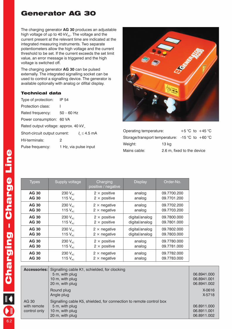
The charging generator AG 30 produces an adjustable high voltage of up to 40 kV . The voltage and the DC
current present at the relevant time are indicated at the integrated measuring instruments. Two separate potentiometers allow the high voltage and the current threshold to be set. If the current exceeds the set limit value, an error message is triggered and the high voltage is switched off.
The charging generator AG 30 can be pulsed externally. The integrated signalling socket can be used to control a signalling device. The generator is available optionally with analog or difital display.
Technical data
Type of protection: IP 54
Protection class: I
Rated frequency: 50 – 60 Hz
Power consumption: 60 VA
Rated output voltage: approx. 40 kV =
Short-circuit output current: I £ 4.5 mAk
HV-terminals: 2
Pulse frequency: 1 Hz, via pulse input
Chargin
g –
Charge L
ine
6.3
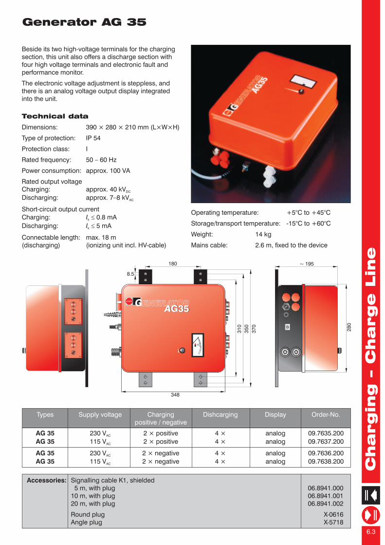
Generator AG 35
Beside its two high-voltage terminals for the charging section, this unit also offers a discharge section with four high voltage terminals and electronic fault and performance monitor.
The electronic voltage adjustment is steppless, and there is an analog voltage output display integrated into the unit.
AG 35 230 V 2 × positive 4 × analog 09.7635.200AC
AG 35 115 V 2 × positive 4 × analog 09.7637.200AC
AG 35 230 V 2 × negative 4 × analog 09.7636.200AC
AG 35 115 V 2 × negative 4 × analog 09.7638.200AC
Types Supply voltage Charging Dishcarging Display Order-No.positive / negative
Accessories: Signalling cable K1, shielded 5 m, with plug 06.8941.00010 m, with plug 06.8941.00120 m, with plug 06.8941.002
Round plug X-0616Angle plug X-5718
Technical data
Dimensions: 390 × 280 × 210 mm (L×W×H)
Type of protection: IP 54
Protection class: I
Rated frequency: 50 – 60 Hz
Power consumption: approx. 100 VA
Rated output voltageCharging: approx. 40 kVDC
Discharging: approx. 7–8 kVAC
Short-circuit output currentCharging: I £ 0.8 mAk
Discharging: I £ 5 mAk
Connectable length: max. 18 m(discharging) (ionizing unit incl. HV-cable)
Operating temperature: +5°C to +45°C
Storage/transport temperature: -15°C to +60°C
Weight: 14 kg
Mains cable: 2.6 m, fixed to the device
28
0
~ 195
kV
kV
31
0
35
0
37
0
180
8.5
348
GG35G35
Operating temperature: +5 °C to +45 °C
Storage/transport temperature: -15 °C to +60 °C
Weight: 13 kg
Mains cable: 2.6 m, fixed to the device
Chargin
g –
Charge L
ine
6.2
Generator AG 30
AG 30 230 V 2 × positive analog 09.7700.200AC
AG 30 115 V 2 × positive analog 09.7701.200AC
AG 30 230 V 2 × negative analog 09.7702.200AC
AG 30 115 V 2 × negative analog 09.7703.200AC
AG 30 230 V 2 × positive digital/analog 09.7800.000AC
AG 30 115 V 2 × positive digital/analog 09.7801.000AC
AG 30 230 V 2 × negative digital/analog 09.7802.000AC
AG 30 115 V 2 × negative digital/analog 09.7803.000AC
AG 30 230 V 2 × positive analog 09.7780.000AC
AG 30 115 V 2 × positive analog 09.7781.000AC
AG 30 230 V 2 × negative analog 09.7782.000AC
AG 30 115 V 2 × negative analog 09.7783.000AC
Types Supply voltage Charging Display Order-No.positive / negative
Accessories: Signalling cable K1, schielded, for clocking 5 m, with plug 06.8941.00010 m, with plug 06.8941.00120 m, with plug 06.8941.002
Round plug X-0616Angle plug X-5718
AG 30 Signalling cable K5, shielded, for connection to remote control boxwith remote 5 m, with plug 06.8911.000control only 10 m, with plug 06.8911.001
20 m, with plug 06.8911.002
The charging generator AG 30 produces an adjustable high voltage of up to 40 kV . The voltage and the DC
current present at the relevant time are indicated at the integrated measuring instruments. Two separate potentiometers allow the high voltage and the current threshold to be set. If the current exceeds the set limit value, an error message is triggered and the high voltage is switched off.
The charging generator AG 30 can be pulsed externally. The integrated signalling socket can be used to control a signalling device. The generator is available optionally with analog or difital display.
Technical data
Type of protection: IP 54
Protection class: I
Rated frequency: 50 – 60 Hz
Power consumption: 60 VA
Rated output voltage: approx. 40 kV =
Short-circuit output current: I £ 4.5 mAk
HV-terminals: 2
Pulse frequency: 1 Hz, via pulse input
Chargin
g –
Charge L
ine
6.3
Generator AG 35
Beside its two high-voltage terminals for the charging section, this unit also offers a discharge section with four high voltage terminals and electronic fault and performance monitor.
The electronic voltage adjustment is steppless, and there is an analog voltage output display integrated into the unit.
AG 35 230 V 2 × positive 4 × analog 09.7635.200AC
AG 35 115 V 2 × positive 4 × analog 09.7637.200AC
AG 35 230 V 2 × negative 4 × analog 09.7636.200AC
AG 35 115 V 2 × negative 4 × analog 09.7638.200AC
Types Supply voltage Charging Dishcarging Display Order-No.positive / negative
Accessories: Signalling cable K1, shielded 5 m, with plug 06.8941.00010 m, with plug 06.8941.00120 m, with plug 06.8941.002
Round plug X-0616Angle plug X-5718
Technical data
Dimensions: 390 × 280 × 210 mm (L×W×H)
Type of protection: IP 54
Protection class: I
Rated frequency: 50 – 60 Hz
Power consumption: approx. 100 VA
Rated output voltageCharging: approx. 40 kVDC
Discharging: approx. 7–8 kVAC
Short-circuit output currentCharging: I £ 0.8 mAk
Discharging: I £ 5 mAk
Connectable length: max. 18 m(discharging) (ionizing unit incl. HV-cable)
Operating temperature: +5°C to +45°C
Storage/transport temperature: -15°C to +60°C
Weight: 14 kg
Mains cable: 2.6 m, fixed to the device
28
0
~ 195
kV
kV
31
0
35
0
37
0
180
8.5
348
GG35G35
Operating temperature: +5 °C to +45 °C
Storage/transport temperature: -15 °C to +60 °C
Weight: 13 kg
Mains cable: 2.6 m, fixed to the device

Chargin
g –
Charge L
ine
6.4
Generator AG 60
AG 60 230 V 2 x positive 4 × disch. Multistat analog 09.7660.200AC
AG 60 115 V 2 x positive 4 × disch. Multistat analog 09.7661.200AC
AG 60 230 V 2 x negative 4 × disch. Multistat analog 09.7662.200AC
AG 60 115 V 2 x negative 4 × disch. Multistat analog 09.7663.200AC
Types Supply voltage Charging Discharging Display Order-No.positive / negative
Accessories: Signalling cable K1, shielded 5 m, with plug 06.8941.00010 m, with plug 06.8941.00120 m, with plug 06.8941.002
Round plug X-0616Angle plug X-5718
The charging generator AG 60 generates an adjustable high voltage of 40 kV . The unit is available DC
with positive and negative polarity. The voltage and the actual current are indicated on the integrated measuring instruments.
The high voltage the current threshold can be set using two separate potentiometers. If the actual current exceeds the set value, an error message is triggered and the high voltage is switched of.
The charging section of the charging generator AG 60 can be pulsed externally. The discharging section allows a signalling device to be controlled using the integrated signalling socket.
Technical data
Dimensions: 390 × 280 × 210 mm (L×W×H)
Type of protection: IP 54
Protection class: I
Rated frequency: 50 – 60 Hz
Power consumption: approx. 140 VA
Output voltageCharge: approx. 40 kVDC
Discharge: approx. 7 – 8 kVAC
Short-circuit output currentCharge: I £ 4.5 mAk
Discharge: I £ 5 mAk
Signalling contacts Load ratingmonitoring: 24 V / 35 V ; max. 50 mAAC DC
Connectable length max. 18 m (discharge): (ionizing unit incl. HV-cable)
Operating temperature: +5 °C to +45 °C
Storage/transport temperature:-15 °C to +60 °C
Weight: 16 kg
Mains cable: 2.6 m, fixed to the device
tt
kVU < 40 kV
kVU < 40 kV
kVU < 40 kV
Chargin
g –
Charge L
ine
6.5
kV
0
24
68
10
kV
~ e
ff.
kV
mA
GG60G60
31
0
35
0
37
0
180
8,5
348
0
28
0
ca. 195
Generator AG 50
The charging generator AG 50 provides excellent per-formance with small dimensions. The adjustable high voltage output enables the operation in a voltage-stabilized mode (figure 1).
Two large digital display indicates the high voltage out-put and the current output. In addition, they signals the states "Overload" and "High voltage output is switched off.“
A signaling socket is the interface to a machine control system or a control console: The high voltage output can be monitored and clocking can be switched back (reset).
The AG 50 is equipped with a function monitoring. This continuously monitors the components of the ionizing-system, from the charging generator via the high-voltage cables up to the connected charging electro-des.
In the case of short circuit or spark formation, for exam-ple by defective cable insulations, the high voltage out-put will be switched off. This state will be signaled at the signaling socket and via the digital displays.
AG 50 2 × positive K1 digital
AG 50 2 × negative K1 digital
Types Supply voltage Charging Signaling socket Display Order-No.positive / negative
100 — 240 V 09.8400.000AC
100 — 240 V 09.8402.000AC
Accessories: Signalling cable K1, shielded 5 m, with plug 06.8941.00010 m, with plug 06.8941.00120 m, with plug 06.8941.002
Round plug X-0616Angle plug X-5718
Technical data
upply voltage: 100 — 240 V AC
(50 - 60 Hz)
50 VA
Output voltage approx.: 0 — 50 kVDC
Short-circuit output curren: ≤ 2 mA
Signalling socket: K1
Signalling contactsload rating: 25 V / 35 V AC DC
≤ 50 mA
HV-terminals: 2
Weight: 8,5 kg
Dimensions: 240 x 150 x 280 mm
(L x H x B)
emperature: +5 °C — +45 °C
temperature: -15 °C — +60 °C
Type of protection: IP 54
Protection class: I
S
Mains cable: 2.6 m(fixed to the device)
Power consumption:
Operating t
Storage/transport
fig. 1: voltage stabilized mode
For example: The high voltage output is set to 40 kV. Up to an output current of approximately 0.5 mA, the high voltage output at the connected charging electrodes remains at 40 kV. Thereafter, the voltage drops in accordance with the electronic power limit and reaching the power limit is indicated.

Chargin
g –
Charge L
ine
6.6
Generator Tristat TR 15 / TR 25
TR 15 230 V positive - - yes 09.7640.000AC
TR 15 115 V positive - - yes 09.7641.000AC
TR 15 230 V negative - - yes 09.7642.000AC
TR 15 115 V negative - - yes 09.7643.000AC
TR 25 230 V positive HV-display yes - 09.7650.000AC
TR 25 115 V positive HV-display yes - 09.7651.000AC
TR 25 230 V negative HV-display yes - 09.7652.000AC
TR 25 230 V negative HV-display yes - 09.7653.000AC
Types Supply voltage Charging Display Clocking Fixed clocking Order-No.socket cable
Accessories: Signalling cable K1, shielded 5 m, with round plug 06.8941.00010 m, with round plug 06.8941.00120 m, with round plug 06.8941.002
Round plug X-0616Angle plug X-5718
The Charging generators Tristat TR 15 / TR 25 supply an adjustable high voltage of approx. 22 kV . The units are available in positive or DC
negative poparity. In case of the TR 25, the voltage set is displayed on the integrated measuring instrument. The high voltage can be steplessly adjusted on a potentiometer. The charging generators Tristat TR 15 / TR 25 can be pulsed using an external control.
The HAUG Chraging generators Tristat TR 15 or TR 25 are high-voltage generators developed specifically for the supply of charging electrodes (types ALT, ALM and ANT).
Technical data
Type of protection: IP 54
Protection class: I
Rated frequency: 50 – 60 Hz
Rated output voltage: approx. 22 kVDC
Short-circuit output current: I £ 3 mAk
HV-terminals: 1
Power consumption: approx. 15 VA
Pulse frequency: 1 Hz, pulse via floating normally open contact
Operating temperature: +5 °C to +45 °C
Storage/transport temperature: -15 °C to +60 °C
Weight: 7 kg
Mains cable: 2.6 m, fixed to the device
16
8
150 ± 2
6.7
269
24
0
20
0
kV
Chargin
g –
Charge L
ine
6.7
Generator AGW (PUR Profibus)
AGW 230 V 2 × positive digital/analog - 09.7715.001AC
AGW 115 V 2 × positive digital/analog - 09.7716.001AC
AGW 230 V 2 × negative digital/analog - 09.7717.001AC
AGW 115 V 2 × negative digital/analog - 09.7718.001AC
AGW DUO 230 V 2 × 2 bipolar digital/analog external 09.7740.000AC
AGW DUO 115 V 2 × 2 bipolar digital/analog control voltage 09.7741.000AC
AGW PUR 230 V 2 × positive - - 09.7715.110AC
Profibus 230 V 2 × negative - - 09.7717.110AC
Typen Supply voltage Charging Display Extras Order-No.
Accessories: Signalling cable K4, shielded 5 m, with control signalling plug 06.8970.00010 m, with control signalling plug 06.8970.00120 m, with control signalling plug 06.8970.002
Control signalling plug X-6155
Bus plug Profibus X-7431
The charging generator AGW / AGW PUR Profibus gene-rates a stabilized adjustable high voltage. The units are available with positive and negative polarity.
On the AGW, the voltage and the actual current are indicated on the integrated digital measuring instruments. In the case of the AGW PUR Profibus, these measured values can also be output through the bus system.
The output voltage and the maximum output current of the AGW can be set optionally using two potentio-meters or an external control voltage. The charging generator AGW can be pulsed externally. The integrated communications socket allows a signalling device to be controlled.
The AGW PUR Profibus allows the output voltage and the maximum current to be adjusted through the bus system. All functions of this unit can be controlled via a Profibus system.
Technical data
Type of protection: IP 30
Class of protection: I
Power consumption: 140 VA
Rated frequency: 50 – 60 Hz
Rated output voltage: 25 kV DC
Output voltage: max. 2.5 mA
External control voltage: 0 – 10 V
Load ratingsignalling contacts: 24 V / 35 V ; max. 50mAAC DC
HV-terminals: 2
Operating temperature: +5 °C to +45 °C
Storage/transport temperature: -15 °C to +60 °C
Weight: 7.5 kg
Mains cable: 2.6 m; fixed to the device
AGW PUR Profibus
AGW
~ 475
13
2.5
14
232
Reset
Local
Remote
Power
kV
mA
U / I
V1.3
kV
mA
0
ENERATOR
AG
WA
GW
58
27.5 380 37
~ 511
Reset
Power
U / I
0
ENERATOR
AG
WA
GW
PU
R P
RO
FIB
US
232 380 37
94

Chargin
g –
Charge L
ine
6.6
Generator Tristat TR 15 / TR 25
TR 15 230 V positive - - yes 09.7640.000AC
TR 15 115 V positive - - yes 09.7641.000AC
TR 15 230 V negative - - yes 09.7642.000AC
TR 15 115 V negative - - yes 09.7643.000AC
TR 25 230 V positive HV-display yes - 09.7650.000AC
TR 25 115 V positive HV-display yes - 09.7651.000AC
TR 25 230 V negative HV-display yes - 09.7652.000AC
TR 25 230 V negative HV-display yes - 09.7653.000AC
Types Supply voltage Charging Display Clocking Fixed clocking Order-No.socket cable
Accessories: Signalling cable K1, shielded 5 m, with round plug 06.8941.00010 m, with round plug 06.8941.00120 m, with round plug 06.8941.002
Round plug X-0616Angle plug X-5718
The Charging generators Tristat TR 15 / TR 25 supply an adjustable high voltage of approx. 22 kV . The units are available in positive or DC
negative poparity. In case of the TR 25, the voltage set is displayed on the integrated measuring instrument. The high voltage can be steplessly adjusted on a potentiometer. The charging generators Tristat TR 15 / TR 25 can be pulsed using an external control.
The HAUG Chraging generators Tristat TR 15 or TR 25 are high-voltage generators developed specifically for the supply of charging electrodes (types ALT, ALM and ANT).
Technical data
Type of protection: IP 54
Protection class: I
Rated frequency: 50 – 60 Hz
Rated output voltage: approx. 22 kVDC
Short-circuit output current: I £ 3 mAk
HV-terminals: 1
Power consumption: approx. 15 VA
Pulse frequency: 1 Hz, pulse via floating normally open contact
Operating temperature: +5 °C to +45 °C
Storage/transport temperature: -15 °C to +60 °C
Weight: 7 kg
Mains cable: 2.6 m, fixed to the device
16
8
150 ± 2
6.7
269
24
0
20
0
kV
Chargin
g –
Charge L
ine
6.7
Generator AGW (PUR Profibus)
AGW 230 V 2 × positive digital/analog - 09.7715.001AC
AGW 115 V 2 × positive digital/analog - 09.7716.001AC
AGW 230 V 2 × negative digital/analog - 09.7717.001AC
AGW 115 V 2 × negative digital/analog - 09.7718.001AC
AGW DUO 230 V 2 × 2 bipolar digital/analog external 09.7740.000AC
AGW DUO 115 V 2 × 2 bipolar digital/analog control voltage 09.7741.000AC
AGW PUR 230 V 2 × positive - - 09.7715.110AC
Profibus 230 V 2 × negative - - 09.7717.110AC
Typen Supply voltage Charging Display Extras Order-No.
Accessories: Signalling cable K4, shielded 5 m, with control signalling plug 06.8970.00010 m, with control signalling plug 06.8970.00120 m, with control signalling plug 06.8970.002
Control signalling plug X-6155
Bus plug Profibus X-7431
The charging generator AGW / AGW PUR Profibus gene-rates a stabilized adjustable high voltage. The units are available with positive and negative polarity.
On the AGW, the voltage and the actual current are indicated on the integrated digital measuring instruments. In the case of the AGW PUR Profibus, these measured values can also be output through the bus system.
The output voltage and the maximum output current of the AGW can be set optionally using two potentio-meters or an external control voltage. The charging generator AGW can be pulsed externally. The integrated communications socket allows a signalling device to be controlled.
The AGW PUR Profibus allows the output voltage and the maximum current to be adjusted through the bus system. All functions of this unit can be controlled via a Profibus system.
Technical data
Type of protection: IP 30
Class of protection: I
Power consumption: 140 VA
Rated frequency: 50 – 60 Hz
Rated output voltage: 25 kV DC
Output voltage: max. 2.5 mA
External control voltage: 0 – 10 V
Load ratingsignalling contacts: 24 V / 35 V ; max. 50mAAC DC
HV-terminals: 2
Operating temperature: +5 °C to +45 °C
Storage/transport temperature: -15 °C to +60 °C
Weight: 7.5 kg
Mains cable: 2.6 m; fixed to the device
AGW PUR Profibus
AGW
~ 475
13
2.5
14
232
Reset
Local
Remote
Power
kV
mA
U / I
V1.3
kV
mA
0
ENERATOR
AG
WA
GW
58
27.5 380 37
~ 511
Reset
Power
U / I
0
ENERATOR
AG
WA
GW
PU
R P
RO
FIB
US
232 380 37
94
Chargin
g –
Charge L
ine
6.8
Generators AG / TR / HW 150
The charging generator AG 150 is available with either positive or negative polarity. The direct voltage output of the charging generator can be set steplessly, and a remote option is also available.
The charging bar ALS is suitable for connection to the charging generator AG 150.
The resistance-coupled charging generator HW 150 is available in either positive or negative polarity. The direct voltage output of the charging generator can be set stepplessly, and a remote option is also available.
The resistance-coupled charging electrode ALW is suitable for connection to the charging generator HW 150.
The charging generator TR 150 is available eith in positive or negative polarity. The direct voltage output of the charging generator can be set steplessly, and a remote option is also available.
The triodes ALT and ALM are suitable for connection to the charging generator TR 150.
16
8
150 ± 2
6.7
269
24
0
20
0
Po
wer
Reset
mA
kV
kV
....
Chargin
g –
Charge L
ine
6.9
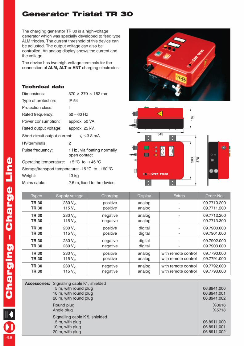
Generator Tristat TR 30
Accessories: Signalling cable K1, shielded 5 m, with round plug 06.8941.00010 m, with round plug 06.8941.00120 m, with round plug 06.8941.002
Round plug X-0616Angle plug X-5718
Signalling cable K 5, shielded 5 m, with plug 06.8911.00010 m, with plug 06.8911.00120 m, with plug 06.8911.002
The charging generator TR 30 is a high-voltage generator which was specially developed to feed type ALM triodes. The current threshold of this device can be adjusted. The output voltage can also be controlled. An analog display shows the current and the voltage.
The device has two high-voltage terminals for the connection of ALM, ALT or ANT charging electrodes.
Technical data
Dimensions: 370 × 370 × 162 mm
Type of protection: IP 54
Protection class: I
Rated frequency: 50 – 60 Hz
Power consumption: approx. 50 VA
Rated output voltage: approx. 25 kV =
Short-circuit output current: I £ 3.3 mAk
HV-terminals: 2
Pulse frequency: 1 Hz , via floating normallyopen contact
Operating temperature: +5 °C to +45 °C
Storage/transport temperature: -15 °C to +60 °C
Weight: 13 kg
Mains cable: 2.6 m, fixed to the device
TR 30 230 V positive analog - 09.7710.200AC
TR 30 115 V positive analog - 09.7711.200AC
TR 30 230 V negative analog - 09.7712.200AC
TR 30 115 V negative analog - 09.7713.300AC
TR 30 230 V positive digital - 09.7900.000AC
TR 30 115 V positive digital - 09.7901.000AC
TR 30 230 V negative digital - 09.7902.000AC
TR 30 230 V negative digital - 09.7903.000AC
TR 30 230 V positive analog with remote control 09.7790.000AC
TR 30 115 V positive analog with remote control 09.7791.000AC
TR 30 230 V negative analog with remote control 09.7792.000AC
TR 30 115 V negative analog with remote control 09.7793.000AC
Typen Supply voltage Charging Display Extras Order-No.2
80
37
0
mAI <
5m
A
kV
TRI TAT TR30
kVm
A
16
2
345

Chargin
g –
Charge L
ine
6.8
Generators AG / TR / HW 150
The charging generator AG 150 is available with either positive or negative polarity. The direct voltage output of the charging generator can be set steplessly, and a remote option is also available.
The charging bar ALS is suitable for connection to the charging generator AG 150.
The resistance-coupled charging generator HW 150 is available in either positive or negative polarity. The direct voltage output of the charging generator can be set stepplessly, and a remote option is also available.
The resistance-coupled charging electrode ALW is suitable for connection to the charging generator HW 150.
The charging generator TR 150 is available eith in positive or negative polarity. The direct voltage output of the charging generator can be set steplessly, and a remote option is also available.
The triodes ALT and ALM are suitable for connection to the charging generator TR 150.
16
8
150 ± 2
6.7
269
24
0
20
0
Po
wer
Reset
mA
kV
kV
....
Chargin
g –
Charge L
ine
6.9
Generator Tristat TR 30
Accessories: Signalling cable K1, shielded 5 m, with round plug 06.8941.00010 m, with round plug 06.8941.00120 m, with round plug 06.8941.002
Round plug X-0616Angle plug X-5718
Signalling cable K 5, shielded 5 m, with plug 06.8911.00010 m, with plug 06.8911.00120 m, with plug 06.8911.002
The charging generator TR 30 is a high-voltage generator which was specially developed to feed type ALM triodes. The current threshold of this device can be adjusted. The output voltage can also be controlled. An analog display shows the current and the voltage.
The device has two high-voltage terminals for the connection of ALM, ALT or ANT charging electrodes.
Technical data
Dimensions: 370 × 370 × 162 mm
Type of protection: IP 54
Protection class: I
Rated frequency: 50 – 60 Hz
Power consumption: approx. 50 VA
Rated output voltage: approx. 25 kV =
Short-circuit output current: I £ 3.3 mAk
HV-terminals: 2
Pulse frequency: 1 Hz , via floating normallyopen contact
Operating temperature: +5 °C to +45 °C
Storage/transport temperature: -15 °C to +60 °C
Weight: 13 kg
Mains cable: 2.6 m, fixed to the device
TR 30 230 V positive analog - 09.7710.200AC
TR 30 115 V positive analog - 09.7711.200AC
TR 30 230 V negative analog - 09.7712.200AC
TR 30 115 V negative analog - 09.7713.300AC
TR 30 230 V positive digital - 09.7900.000AC
TR 30 115 V positive digital - 09.7901.000AC
TR 30 230 V negative digital - 09.7902.000AC
TR 30 230 V negative digital - 09.7903.000AC
TR 30 230 V positive analog with remote control 09.7790.000AC
TR 30 115 V positive analog with remote control 09.7791.000AC
TR 30 230 V negative analog with remote control 09.7792.000AC
TR 30 115 V negative analog with remote control 09.7793.000AC
Typen Supply voltage Charging Display Extras Order-No.
28
0
37
0
mAI <
5m
A
kV
TRI TAT TR30
kVm
A
16
2
345

Chargin
g –
Charge L
ine
6.10
Charging bars ALS A / ALS R
The HAUG charging bar ALS is suitable for most applications where material webs are to be fixed relative to each other. The charging bar can be supplied using any HAUG AG-series charging generator.
The charging bar ALS must be attached at a distance of approx. 10 – 20 mm above the material to be charged, directly above the counter-electrode. The grounded counter-electrode must make contact with the material to be charged.
The charging bar ALS is available both with axial and radial exit of the high-voltage cable. The high-voltage cable and the pin strip can be simply replaced.
Technical data
Dimensions: 30 × 40 mm (
Bar length: available from 200 mm to 2000 mm
Operting temperature: +5 °C to + 45 °C
Storage/transport temperature: -15 °C to +60 °C
Construction: special synthetic material made to stand high-voltage, compact desing, enclosed all round. Mounting screws M10×40, T-nut running the whole length of the bar, optimal installation possible
ALS A, ALS R)
ALS A 200 – 2.000 standard version with detachable HC-cable,axial cable connection 08.8710.000
ALS R 200 – 2.000 standard version with detachable HV-cable,radial cable connection 08.8711.000
ALS R 200 – 2.000 radial cable connection, cable outgoing on the right 08.8725.000
ALS R 200 – 2.000 radial cable connection, cable outgoing on the left 08.8726.000
Types Lengths Specification Order-No.
Accessories: HV-cable for axial cable connections 06.2220.000HV-cable for radial cable connections 06.2225.000
Single cable for ALS A 06.2220.001Single cable for ALS R 06.2225.001
Pin strip for ALS A, exchangeable 06.8938.001Pin strip for ALS R, exchangeable 06.8938.002
Cover for partial screening X-5099Bar holder (plastics), straight version 10.0197.000Bar holder (plastics), angle version 10.0198.000Mounting screw (plastics) M10 X-4357Nut (plastics) M10 X-4185Disc (plastics) Ø 10.5 X-4145
ALS R right radial 08.8726.000
left08.8725.000
200
– 20
00 M10
ALS A 08.8710.000
ALS R 08.8711.000radial
200 – 2000
90
M10
200 – 2000 45
M10
40
30
Chargin
g –
Charge L
ine
6.11
Generators AG / TR / HW 150
Variants
AG 150 A 230 V 1 × positive digital - 09.7770.001AC
AG 150 A 115 V 1 × negative digital - 09.7772.001AC
AG 150 S 230 V 1 × positive - - 09.7770.002AC
AG 150 S 115 V 1 × negative - - 09.7772.000AC
HW 150 A 230 V 1 × positive digital - 09.7760.001AC
HW 150 A 115 V 1 × negative digital - 09.7762.000AC
HW 150 B 230 V 1 × positive - with profibus 09.7760.004AC
HW 150 B 115 V 1 × negative - with profibus 09.7762.004AC
HW 150 S 230 V 1 × positive - remote controlled 09.7760.002AC
HW 150 S 115 V 1 × negative - remote controlled 09.7762.002AC
TR 150 A 230 V 1 × positive digital triggering via 09.7720.001AC
TR 150 A 115 V 1 × negative digital potentiometer 09.7722.001AC
TR 150 P 230 V 1 × positive - triggering 09.7720.002AC
TR 150 P 115 V 1 × negative - with 4 – 20 mA 09.7722.002AC
TR 150 S 230 V 1 × positive - triggering 09.7720.003AC
TR 150 S 115 V 1 × negative - with 0 – 10 V 09.7722.003AC
Types Supply voltage Charging Display Extras Order-No.positive / negative
Accessories: Signalling cable K1, shielded 5 m, with plug 06.8941.00010 m, with plug 06.8941.00120 m, with plug 06.8941.002
Round plug X-0616Angle plug X-5718
Signalling cable K2, shielded
5 m, mit cable plug 06.6198.00010 m, mit cable plug 06.6198.00120 m, mit cable plug 06.6198.002
Cable plug X-6198Cable angle plug X-6236
Technical data
Dimensions: 270 × 170 × 150 (B×H×T)
Type of protection: IP 54
Protection class: I
HV-terminals: 1 (AG)
Power consumption: approx. 30 VA
Output voltage: U = 15 kV ±10%max.
Output current: I = 0.3 mA ±15%max.
Signalling contacts Contact rating monitoring: max. 24 V / 35 V , max. 50 mAAC DC
Pulse frequency6via pulse input: max. 1 Hz (max. 10 cycles)
Recorery time after overload switch-off: < 10 s
Operating temperature: +5 °C to +45 °C
Storage/transport temperature: -15 °C to +60 °C
Weight: 7 kg
Mains cable: 2,6 m, fixed to the device
Digital display Over current Remote control Pulsing Reset Monitor output
A Voltage Switch-off - floating normally floating normally 0 – 10 Vand current open contact open contact
S - Switch-off 0 – 10 V 24 V 24 V 0 – 10 VDC DC
P - Switch-off 4 – 20 mA floating normally floating normally 4 – 20 mAopen contact open contact

Chargin
g –
Charge L
ine
6.12
Charging triodes ALT / ANT / ALM
HAUG charging triodes are characterized by a very homogenous field at the charging pins. As a result of the special geometric design of the charging triode, spark-overs to the counter-electrode are impossible. The charging triode can therefore be mounted at a distance of as little as approx. 10 mm from the material to be charged. The charging triode provides a very high charge even at low voltages and thus ensures very good adhesion.
Due to their simple design using magnetic clamps, worn charging pins can be easily exchanged. The charging triode is connected using a shielded high-voltage cable.
The triodes ANT and ALM / ALT are suitable for use for connection to charging generators of the TR-series.
Anti-neck-in-Triode ANT
The anti-neck-in-triode ANT guarantees the optimal exploitation of the rim of the fusing field and simultaneously serves to suppress the well-known "neck-in-effect" in the extrusion of film. The triode is heat-resistant up to approx. +130 °C.
ALT
exchangeable pin strip30
shielded co-axial cablesmallest bending radius R 50
Ø 10
lenght = customized
60
60
70
Ø 28
spring-loaded earthing sleeve
Ø 2
9
connection thread M 27 × 1.5
Technical data ANT
Operating temperature: +5 °C to +130 °C
Storage/transport temperature: -15 °C to +60 °C
Technical data ALM / ALT
Operating temperature: +5 °C to +50 °C
Storage/transport temperature: -15 °C to +60 °C
ANT
Chargin
g –
Charge L
ine
6.13
Resistance-coupled charging electrode ALW
By limiing the current using resistors, the generation of hard sparks can be reliably prevented, thus signi-ficantly reducing possible damage to or impairment of electronic machine controls.
The charging electrode ALW is connected with a detachable, shielded high-voltage cable and can be supplied with a radial or axial HV-connection. The bar profile is manufactured from glass fiber reinforced plastics which is also suitable for use at higher temperatures. A t-slot along the back of the ALW allows convenient installation over the whole width of the bar.
The resistance-coupled charging electrode ALW is recommended, in particular, for applications with increased risk of spark generation and consequently of damage to high-grade surfaces or electronoc components. Conceivable scenarios include situations where the counter-electrode required for charging is not always covered completely by the material to be charged, e.g. where two-dimensional material webs of varying width are charged or where there is an uncovered gap between cut or individual materials on the substrate acting as counter-electrode.
Technical data
Bar profile: glass fibre reinforced plastics, compact design
Dimensions: 30 × 64 mm
Bar length: minimum length: 80 mmmaximum length: 2000 mmlength intervals: 30 mm
ALW A 80 – 2.000 axial cable connection 08.8790.000
ALW R 80 – 2.000 radial cable connection 08.8791.000
Types Lengths Specification Order-No.
Accessories: HV-cable for axial connections 06.2268.000HV-cable for radial connections 06.2269.000
Single cable for ALW A 06.2268.001Single cable for ALW R 06.2269.001
ALW radial connection
length = customized
~ 35
95
64
28
30
M8×40
ALW axial connection
length = customized
95

Chargin
g –
Charge L
ine
6.14
ALT 60 × 50 × 30 with co-axial contact, cable outgoing centered 08.8650.000
Types Dimensions Specification Order-No.
ANT 110 × 60 × 30 with co-axial contact, cable outgoing centered 08.8750.110
Type Dimensions Specification Order-No.
ALM A 60 × 30 Length 200 – 1000 mm, with co-axial contact, axial cable outgoing 08.8752.000
ALM R 60 × 30 Length 200 – 1000 mm, with co-axial contact, radial cable outgoing 08.8751.000
ALM GFK A 64 × 30 Length 200 – 4000 mm, reinforced version,with co-axial contact, axial cable outgoing 08.8781.000
ALM GFK R 64 × 30 Length 200 – 4000 mm, reinforced version,with co-axial contact, radial cable outgoing 08.8780.000
Types Dimensions Specifications Order-No.
Accessoreis: Pin strip, exchangeable X-1696HV-cable, standard length 2 m 06.2250.200Single cable, co-axial 06.2250.001
Accessories: Pin strip, exchangeable X-2314HV-cable, standard length 2 m 06.2252.200Single cable, co-axial 06.2252.001
Accessories: Pin strip, exchangeable 06.8938.001HV-cable, standard length 2 m 06.2251.200Single cable, co-axial 06.2254.001Cover for partial screening X-5099
60
60
30L = 60 mm – 1000 mm
28
ALM
Charging triodes ALT / ANT / ALM
ALM