information agent technology in process automation systems
TRANSCRIPT

HELSINKI UNIVERSITY OF TECHNOLOGY
Department of Automation and Systems Technology
Information and Computer Systems in Automation
Master's Thesis
Antti Pakonen
Information Agent Technology in Process Automation Systems
Thesis submitted in partial fulfilment of the requirements for the degree of Master of Science.
Espoo, November 26, 2004
Supervisor Professor Kari Koskinen
Instructor Teemu Tommila
Helsinki University of Technology Abstract of the Master's Thesis
Author: Name of the Thesis: Date:
Antti Pakonen Information Agent Technology in Process Automation Systems 26.11.2004 Number of pages: 89
Deparment: Professorship:
Department of Automation and Systems Technology AS-116 Information and Computer Systems in Automation
Supervisor: Instructor:
Professor Kari Koskinen Teemu Tommila, M. Sc. (Tech.)
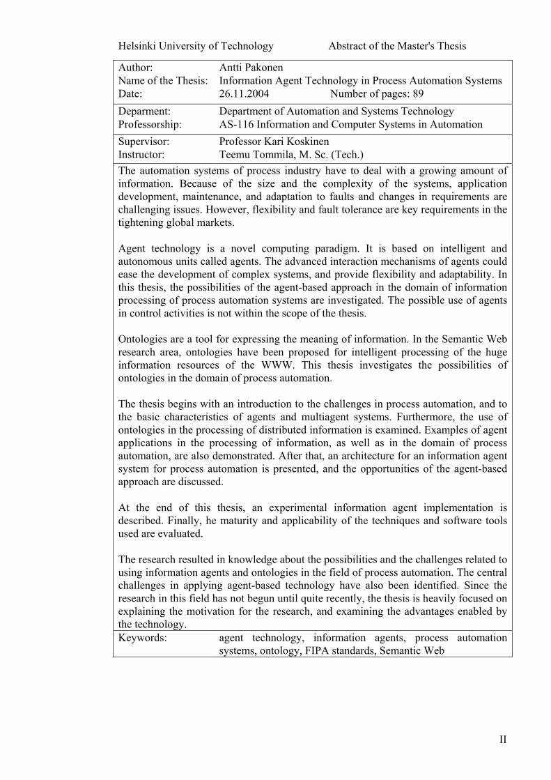
The automation systems of process industry have to deal with a growing amount of information. Because of the size and the complexity of the systems, application development, maintenance, and adaptation to faults and changes in requirements are challenging issues. However, flexibility and fault tolerance are key requirements in the tightening global markets. Agent technology is a novel computing paradigm. It is based on intelligent and autonomous units called agents. The advanced interaction mechanisms of agents could ease the development of complex systems, and provide flexibility and adaptability. In this thesis, the possibilities of the agent-based approach in the domain of information processing of process automation systems are investigated. The possible use of agents in control activities is not within the scope of the thesis. Ontologies are a tool for expressing the meaning of information. In the Semantic Web research area, ontologies have been proposed for intelligent processing of the huge information resources of the WWW. This thesis investigates the possibilities of ontologies in the domain of process automation. The thesis begins with an introduction to the challenges in process automation, and to the basic characteristics of agents and multiagent systems. Furthermore, the use of ontologies in the processing of distributed information is examined. Examples of agent applications in the processing of information, as well as in the domain of process automation, are also demonstrated. After that, an architecture for an information agent system for process automation is presented, and the opportunities of the agent-based approach are discussed. At the end of this thesis, an experimental information agent implementation is described. Finally, he maturity and applicability of the techniques and software tools used are evaluated. The research resulted in knowledge about the possibilities and the challenges related to using information agents and ontologies in the field of process automation. The central challenges in applying agent-based technology have also been identified. Since the research in this field has not begun until quite recently, the thesis is heavily focused on explaining the motivation for the research, and examining the advantages enabled by the technology. Keywords: agent technology, information agents, process automation
systems, ontology, FIPA standards, Semantic Web
II
Teknillinen Korkeakoulu Diplomityön tiivistelmä
Tekijä: Työn nimi: Päivämäärä:
Antti Pakonen Informaatioagenttiteknologia prosessiautomaatiojärjestelmissä 26.11.2004 Sivumäärä: 89
Osasto: Professuuri:
Automaatio- ja systeemitekniikan osasto AS-116 Automaation tietotekniikka
Valvoja: Ohjaaja:
Professori Kari Koskinen Teemu Tommila, DI
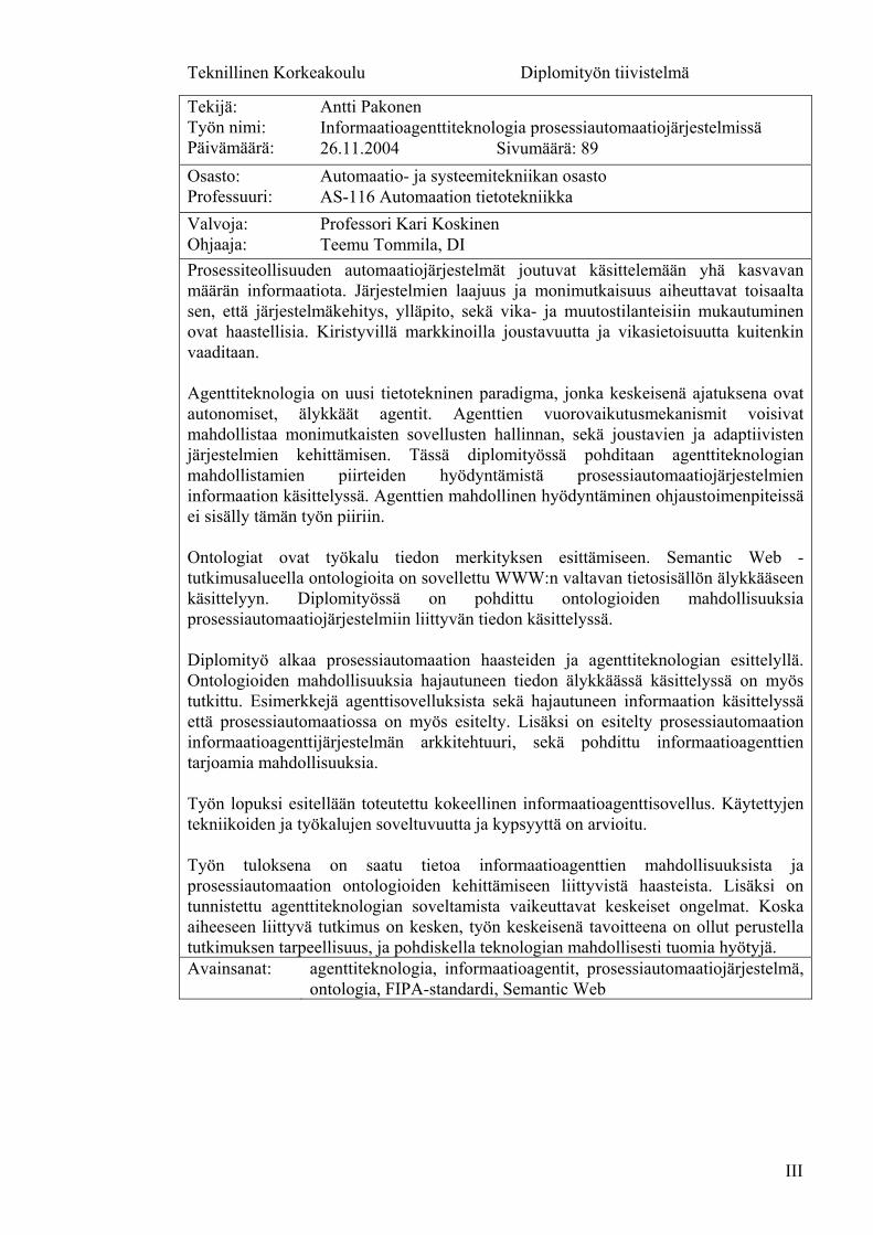
Prosessiteollisuuden automaatiojärjestelmät joutuvat käsittelemään yhä kasvavan määrän informaatiota. Järjestelmien laajuus ja monimutkaisuus aiheuttavat toisaalta sen, että järjestelmäkehitys, ylläpito, sekä vika- ja muutostilanteisiin mukautuminen ovat haastellisia. Kiristyvillä markkinoilla joustavuutta ja vikasietoisuutta kuitenkin vaaditaan. Agenttiteknologia on uusi tietotekninen paradigma, jonka keskeisenä ajatuksena ovat autonomiset, älykkäät agentit. Agenttien vuorovaikutusmekanismit voisivat mahdollistaa monimutkaisten sovellusten hallinnan, sekä joustavien ja adaptiivisten järjestelmien kehittämisen. Tässä diplomityössä pohditaan agenttiteknologian mahdollistamien piirteiden hyödyntämistä prosessiautomaatiojärjestelmien informaation käsittelyssä. Agenttien mahdollinen hyödyntäminen ohjaustoimenpiteissä ei sisälly tämän työn piiriin. Ontologiat ovat työkalu tiedon merkityksen esittämiseen. Semantic Web -tutkimusalueella ontologioita on sovellettu WWW:n valtavan tietosisällön älykkääseen käsittelyyn. Diplomityössä on pohdittu ontologioiden mahdollisuuksia prosessiautomaatiojärjestelmiin liittyvän tiedon käsittelyssä. Diplomityö alkaa prosessiautomaation haasteiden ja agenttiteknologian esittelyllä. Ontologioiden mahdollisuuksia hajautuneen tiedon älykkäässä käsittelyssä on myös tutkittu. Esimerkkejä agenttisovelluksista sekä hajautuneen informaation käsittelyssä että prosessiautomaatiossa on myös esitelty. Lisäksi on esitelty prosessiautomaation informaatioagenttijärjestelmän arkkitehtuuri, sekä pohdittu informaatioagenttien tarjoamia mahdollisuuksia. Työn lopuksi esitellään toteutettu kokeellinen informaatioagenttisovellus. Käytettyjen tekniikoiden ja työkalujen soveltuvuutta ja kypsyyttä on arvioitu. Työn tuloksena on saatu tietoa informaatioagenttien mahdollisuuksista ja prosessiautomaation ontologioiden kehittämiseen liittyvistä haasteista. Lisäksi on tunnistettu agenttiteknologian soveltamista vaikeuttavat keskeiset ongelmat. Koska aiheeseen liittyvä tutkimus on kesken, työn keskeisenä tavoitteena on ollut perustella tutkimuksen tarpeellisuus, ja pohdiskella teknologian mahdollisesti tuomia hyötyjä. Avainsanat: agenttiteknologia, informaatioagentit, prosessiautomaatiojärjestelmä,
ontologia, FIPA-standardi, Semantic Web
III

Preface
It has been a privilege to work at VTT Industrial Systems. I am grateful for having had the opportunity to work on my master's thesis without compromising much of my free time or mental health. I wish to thank my superiors and fellow employees for a supportive and inspiring work environment.
I want to thank my instructor Teemu Tommila for his expertise and for keeping track of my progress. I also want to thank my supervisor, Professor Kari Koskinen. It has been rewarding to study in a laboratory well managed.
For collaboration in the MUKAUTUVA project I thank project manager Peci Appelqvist and Ilkka Seilonen from Helsinki University of Technology; Petteri Kangas from VTT Industrial Systems; Jari Holm, Teppo Mattsson, and the friendly operators from UPM; Mika Karaila, Esa Salonen and everybody else involved at Metso Automation. Also thanks to Pekka Aarnio from Helsinki University of Technology for valuable comments.
I am enormously grateful for having had the chance to work with the multitalented Teppo Pirttioja of Helsinki University of Technology. Thank you for much guidance and a healthy attitude towards things. And, of course, for sharing that renowned "Pirttioja's vision".
Most of all, I have to thank my family, friends and relatives for supporting me and for believing in me more than I ever did.
Silke, thank you so much for everything. Let us now party.
(Tähän sit vielä joku hauska sitaatti)
Espoo, November 2004 Antti Pakonen
IV

Table of Contents
1 Introduction .......................................................................................................1
1.1 Background .........................................................................................................1
1.2 Objective .............................................................................................................2
1.3 Methodology .......................................................................................................3
1.4 Structure ..............................................................................................................3
2 Process Automation and Information Systems ..............................................4 2.1 Process automation systems................................................................................4
2.2 Process automation system integration ...............................................................7
2.3 Challenges for future process automation systems .............................................8
3 Agent Technology............................................................................................10 3.1 Agents ...............................................................................................................10
3.2 Multiagent systems............................................................................................13
3.3 FIPA specifications ...........................................................................................15
3.4 Agent-orientated software engineering.............................................................18
4 Ontologies in Information Processing ...........................................................19 4.1 Ontologies .........................................................................................................20
4.2 Ontology languages and the Semantic Web......................................................23
4.3 Ontologies in agent systems..............................................................................27
4.4 Ontologies in process automation .....................................................................29
5 Agent Technology in Information Processing ..............................................32 5.1 Characteristics of information agent systems ...................................................33
5.2 Agent applications in information processing ..................................................35
5.3 Web Services and agent-based systems ............................................................40
6 Agent Technology in Process Automation ....................................................41 6.1 Agent applications in process automation ........................................................41
6.2 Agent-based control applications......................................................................46
7 Bleaching of Mechanical Pulp........................................................................52 7.1 Chemistry of hydrogen peroxide bleaching ......................................................52
7.2 Process equipment in peroxide bleaching .........................................................53
7.3 Process control in bleaching .............................................................................54
7.4 Challenges to bleach plant control ....................................................................55
V
8 Architecture of an Information Agent System for Process Automation ......................................................................................................56
8.1 Architecture of the agent society ......................................................................57
8.2 Internal structure of the agents..........................................................................60
8.3 Agent communication .......................................................................................61
8.4 Future considerations ........................................................................................63
9 Implementation of the Agent System ............................................................64 9.1 Software tools....................................................................................................64
9.2 Modules.............................................................................................................66
9.3 Plans ..................................................................................................................69
9.4 Domain ontology...............................................................................................70
9.5 Agent world model............................................................................................71
9.6 User interface ....................................................................................................72
10 Tests ..................................................................................................................73 10.1 Test scenario: sensor monitoring ......................................................................73
10.2 Test configuration .............................................................................................75
10.3 Test run..............................................................................................................77
10.4 Test conclusions ................................................................................................80
11 Conclusions ......................................................................................................81 11.1 Summary and conclusions.................................................................................81
11.2 Evaluation of the techniques and tools used .....................................................82
11.3 Future challenges ..............................................................................................83
12 References ........................................................................................................84
VI
Abbreviations AID Agent Identifier AOSE Agent-Orientated Software Engineering AP Agent Platform AMS Agent Management System BDI Belief-Desire-Intention CORBA Common Object Request Broker Architecture COTS Commercial-Off-The-Shelf CRM Customer Relationship Management DAML DARPA Agent Markup Language DCS Distributed Control System DF Directory Facilitator EAI Enterprise Application Integration EDI Electronic Data Interchange ERP Enterprise Resource Planning FIPA Foundation for Intelligent Physical Agents HMI Human-Machine Interface HMS Holonic Manufacturing Systems IEC International Electrotechnical Commission IT Information Technology KQML Knowledge Query and Manipulation Language MES Manufacturing Execution System MOF Meta Object Facility MTS Message Transport Service NZDIS The New Zealand Distributed Information Systems ODBC Open DataBase Connectivity OIL Ontology Inference Layer OKBC Open Knowledge Base Connectivity OLE Object Linking and EmbeddOMG Object Management Group
ing
OPC OLE for Process Control OQL Object Query Language
OWL Ontology Web Language PLC Programmable Logic Controller
on Framework RDF Resource DescriptiRDFS RDF Schema
A ta Acquisition SCAD Supervisory Control And DaSCM Supply Chain Management SL Semantic Language UML Unified Modeling Language
XML eXtensible Markup Language
WWW World Wide Web W3C World Wide Web ConsortiumXSLT XML Transformations
VII
1 Introduction
1.1 Background The nature of process automation systems is shifting towards information systems. Process automation systems have to deal with a rapidly growing amount of information. The increase in the amount of instrumentation, the increase in the intelligence of field devices, and the vertical integration to enterprise resource planning systems, among other factors, also cause the information to be more and more distributed.
The heterogeneity of the information in different information sources, however, makes it difficult to utilise the information produced by e.g. intelligent field devices. The development of different interfacing technologies has provided us with a uniform access to distributed information systems, but we still lack the methods to automatically process and refine distributed information into coherent knowledge.
The amount of information can easily become a safety issue. In the event of a critical failure the flood of resulting alarms does not help an operator in decision making. The system should therefore be able to automatically refine and filter information. To enable this, the automation system must possess built-in "understanding" of the structure and function of the underlying process system. This kind of understanding would also enable the automation system to make conclusions about the performance of the system in a normal state, and to suggest reasonable measures to be taken by the operator.
On the other hand, the tightening market demands present further requirements to the agility of automation systems. Large process plants cannot afford long breaks in production. Automation systems should therefore be capable of adapting to changes and even unexpected failure scenarios rapidly. We should be able to add new devices into the system in a plug-and-play fashion at runtime. In addition, fault diagnostics features should be more intelligent and anticipatory to support early recovery.
To address these challenges, we evidently need a distributed, modular, dynamic and flexible approach to processing vast amounts of heterogeneous, alternating information on different levels of abstraction. The distribution of information processing capabilities to increasingly intelligent field devices would indeed support distribution and modularisation.
Agent-orientated software engineering is a novel approach to building complex, distributed software systems. Systems are modelled as societies of autonomous, proactive, flexible agents which interact with their environment in order to achieve defined goals. Interactions between agents in multiagent systems are modelled after human communication, offering semantically rich methods of interaction.
1

Ontologies, on the other hand, are a proposed solution to the current challenges of knowledge management. Explicit domain conceptualisations that can be processed by computer, ontologies, are a Semantic Web -technology which aims at improving the information searching and processing capabilities of the Internet. Ontologies are also a foundation for agent information exchange.
Information agents are agents that have access to multiple, heterogeneous information sources, actively searching for relevant information on behalf of their users. Information agents utilising process automation domain ontologies seem to be able to tackle the challenges presented above. The necessary communication could be reduced and rationalised as agents would exchange refined knowledge instead of raw data. Ontologies could support the refinement of vast amounts of raw data into coherent knowledge. The agent society that would constitute the system could be able to act in a dynamic, flexible manner even in situations unforeseeable at the system design time.
1.2 Objective This thesis is a part of the research project "Adaptation principles and mechanisms in automation applications" (Automaatiosovellusten mukautumisperiaatteet- ja mekanismit (MUKAUTUVA)), conducted under the national technology programme "Intelligent Automation Systems". The MUKAUTUVA project aims at investigating the prospects of agent technology in the information handling of process automation systems, with emphasis on the adaptation to varying situations and requirements.
The objective of the thesis is to provide a review of the characteristics of multiagent systems and to introduce the possibilities of ontologies in information processing. The aim is also to demonstrate how information agents and ontologies could improve information processing in process automation systems, thus rationalising the motivation for our research.
From a more technical point of view, the objective is to examine the possibilities of the agent-based mechanisms in the application domain, and to evaluate the features and the performance of state-of-the-art software tools.
Within the thesis, an information agent refers to a software agent that processes and refines information on a separate add-on layer above the conventional process automation system. An information agent does not participate directly in process control activities, but assists the operators in making decisions and detecting anomalies. Since the somewhat immature technology is yet to be proven reliable, process control agents are regarded as a solution of the more distant future in the field of process automation.
2
1.3 Methodology The thesis begins with a broad literature review. The intention is that the review can be used separately as a solid introduction to the subject. Since the research into the use of agent technology in process automation has begun only recently, much attention is paid to the few research applications devised.
A prototype agent system was constructed in order to experiment with the agent-based mechanisms, and to evaluate state-of-the-art software tools. The prototype system was tested in a demonstration scenario that was motivated by a shortcoming in the current process automation systems.
1.4 Structure The thesis is organised in the following way:
Chapter 2, Process Automation and Information Systems, takes a brief look at the characteristics of the current automation and information systems in the domain of process control.
Chapter 3, Agent Technology, presents the basic concepts related to agents and multiagent systems and briefly introduces the available technology involved.
Chapter 4, Ontologies in Information Processing, presents a solution to the current challenges of knowledge management and examines the preconditions for its adaptation to the domain of process automation.
Chapter 5, Agent Technology in Information Processing, examines how agent technology and ontologies could improve the processing of information in complex, distributed systems.
Chapter 6, Agent Technology in Automation, presents the motivations for applying agent technology to the field of agent technology, as well as some ready agent applications.
Chapter 7, Bleaching of Mechanical Pulp, briefly presents our demonstration process.
Chapter 8, Architecture of an Information Agent System for Process Automation, presents an agent-based approach to information processing in process automation systems. The architecture is a result of the MUKAUTUVA project.
Chapter 9, Implementation of the Agent System, describes an experimental implementation of the proposed agent-based approach.
Chapter 10, Tests, presents our demonstration scenario and the results of the tests.
Chapter 11, Conclusions, summarises the thesis, and presents the essential future challenges.
3
2 Process Automation and Information Systems
Since the dawn of computer-based automation systems in the early 1960s, the development of automation has followed progress in information technologies. The first directly computer-controlled systems consisted of a mainframe computer controlling an entire plant. Actual applications were limited by unreliability. 1970s saw the emergence of digital distributed control systems (DCS).
Since the late 1980s, PC technology has gradually found its way into industrial applications. The progress of automation systems has been affected by evolution of IT in terms of hardware, software and applications. The automation systems of today integrate basic automation, machine control, quality control and condition monitoring. Knowledge and information management have become essential parts of the delivered application.
Recently, the development of automation has shifted from physical systems towards applications. Automation providers have become suppliers of solutions, and the traditional term DCS no longer describes all the functions and applications found in an automation application. At present, we are witnessing a shift from the age of DCS to an IT-based network architecture.
[KnowPap]
Current automation systems have to face diverse requirements. Tightening markets require integration and global optimisation. Customers call for cheap, custom-built, high-quality products with minimal time of delivery, and support for the entire life cycle. Production has to be agile, safe, and friendly to the environment. Large and complex production systems have to be managed with high availability and flexibility. The role of information technology is crucial in achieving these goals. [Tommila et al. 2001]
2.1 Process automation systems ISA (The Instrumentation, Systems, and Automation Society) has proposed a hierarchy model for the levels and domains of control in manufacturing industries (Figure 1). In the model, level 4 represents functions of the enterprise domain, covered by Enterprise Resource Planning (ERP) or Supply Chain Management (SCM) systems. The lower levels deal with the domain of control.
4

Figure 1. The functional hierarchy of different automation and information systems in manufacturing industries. Level 4 represents enterprise functions, levels 3 to 0 deal
with the domain of control. [ISA 2000]
Levels 2, 1 and 0 define the cell or line supervision functions, operations functions, and process control functions. [ISA 2000] A standard reference model for batch control processes has been proposed by ISA. [ISA 1995] The activities of the batch control reference model can to some extent also be applied for continuous process. These control activities include:
• process control
• unit supervision
• process management
• production planning and scheduling
• production information management
[ISA 1995]
The activities of the control level and the MES systems clearly overlap, as do the activities of levels 3 and 4 in the ISA model. The standards assume that all activities are not explicitly defined at each level. [ISA 2000]
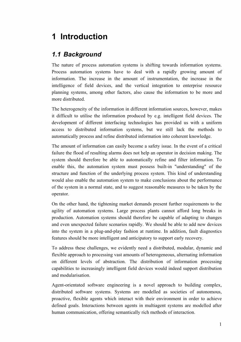
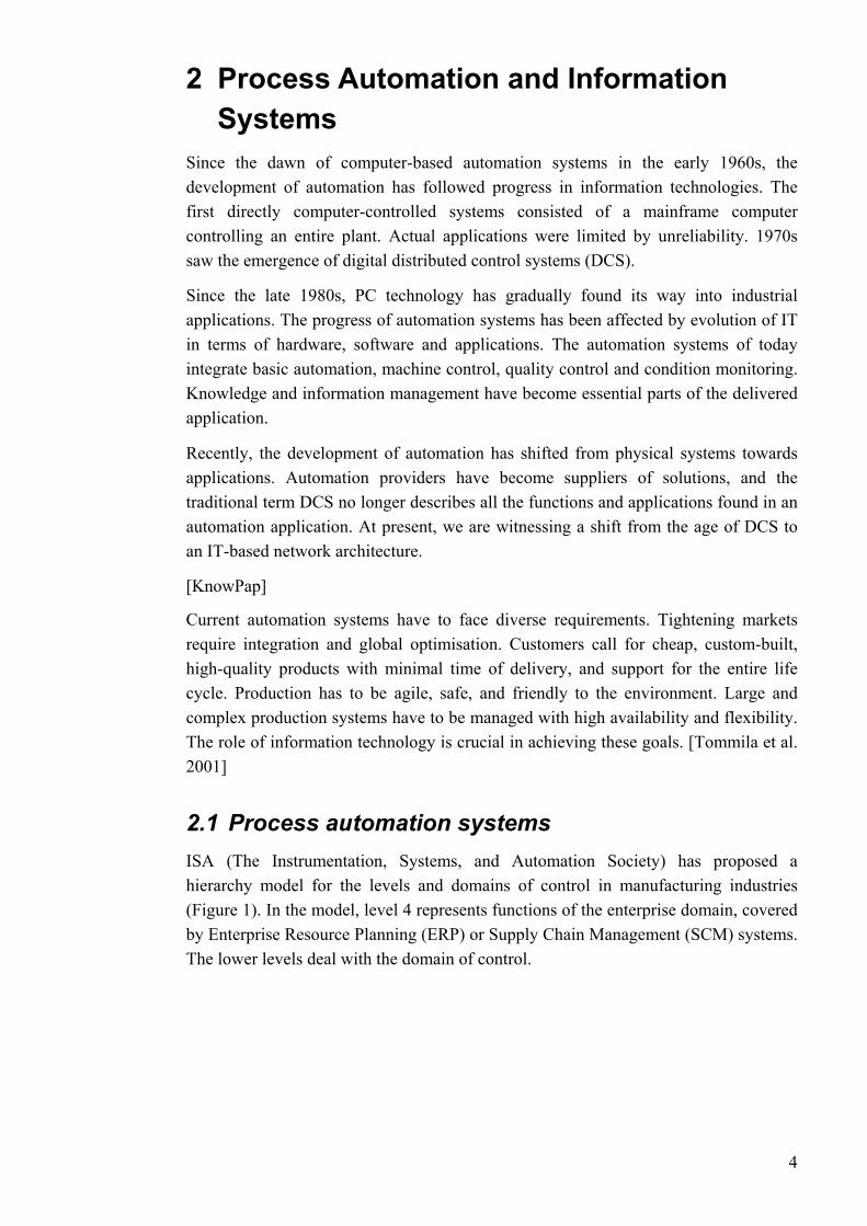
The automation of an entire process plant can be thought of as a process beginning with field equipment and ending with plant information systems (Figure 2). At the top of the pyramid, the time scale for activities can range from days to months. Moving down the pyramid, the number of functions and time-criticalness increase. At the bottom, the time scale ranges from milliseconds to hours. Moving up, information is refined and reduced. [KnowPap]
5
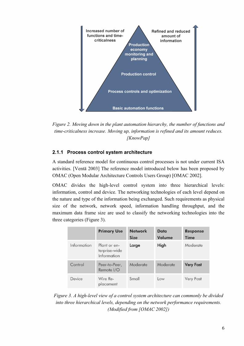
Figure 2. Moving down in the plant automation hierarchy, the number of functions and time-criticalness increase. Moving up, information is refined and its amount reduces.
[KnowPap]
2.1.1 Process control system architecture
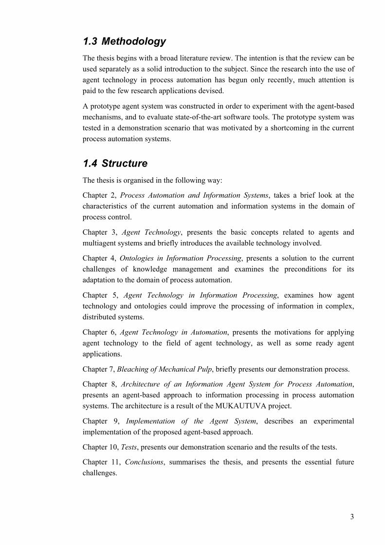
A standard reference model for continuous control processes is not under current ISA activities. [Ventä 2003] The reference model introduced below has been proposed by OMAC (Open Modular Architecture Controls Users Group) [OMAC 2002].
OMAC divides the high-level control system into three hierarchical levels: information, control and device. The networking technologies of each level depend on the nature and type of the information being exchanged. Such requirements as physical size of the network, network speed, information handling throughput, and the maximum data frame size are used to classify the networking technologies into the three categories (Figure 3).
Figure 3. A high-level view of a control system architecture can commonly be divided into three hierarchical levels, depending on the network performance requirements.
(Modified from [OMAC 2002])
6

The typical control system architecture for continuous process - as proposed by OMAC - consists of a variety of controllers, as well as associated devices and interfaces (Figure 4). The process control stations, HMIs, and history databases reside at both the control network and the process network. The PLCs and process controllers run the control loops and sit on the control network. Field devices and their associated I/O are connected via device networks.
Figure 4. A system-level architecture for continuous process manufacturing as proposed by OMAC. The controllers and associated devices and interfaces are
connected by different networks. [OMAC 2002]
[OMAC 2002]
2.2 Process automation system integration Process control systems typically consist of devices and software components from a wide range of vendors. Communication between devices and systems requires different data buses and networks. Typically, system integration needs an amount of tailoring, and interoperation is limited. Changes within one subsystem may influence the whole automation system. [Leiviskä 1999]
The current trend is towards open automation systems. The objective is to allow easy integration of systems components from different vendors, and to have all the information available for all applications. Subsystems can share databases, applications and interfaces. [Leiviskä 1999]
In addition to the integration on the technical level, there is also a need for integration of control functions on different hierarchical levels. [Tommila et al. 2001] The demand for agile production systems calls for vertical integration of the operational systems spanning from field devices to supply chain management systems ( ). Interoperability of control functions across the vertical layers is needed to ensure that
Figure 5
7
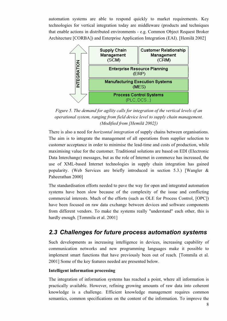
automation systems are able to respond quickly to market requirements. Key technologies for vertical integration today are middleware (products and techniques that enable actions in distributed environments - e.g. Common Object Request Broker Architecture [CORBA]) and Enterprise Application Integration (EAI). [Hemilä 2002]
Figure 5. The demand for agility calls for integration of the vertical levels of an operational system, ranging from field device level to supply chain management.
(Modified from [Hemilä 2002])
There is also a need for horizontal integration of supply chains between organisations. The aim is to integrate the management of all operations from supplier selection to customer acceptance in order to minimise the lead-time and costs of production, while maximising value for the customer. Traditional solutions are based on EDI (Electronic Data Interchange) messages, but as the role of Internet in commerce has increased, the use of XML-based Internet technologies in supply chain integration has gained popularity. (Web Services are briefly introduced in section 5.3.) [Wangler & Paheerathan 2000]
The standardisation efforts needed to pave the way for open and integrated automation systems have been slow because of the complexity of the issue and conflicting commercial interests. Much of the efforts (such as OLE for Process Control, [OPC]) have been focused on raw data exchange between devices and software components from different vendors. To make the systems really "understand" each other, this is hardly enough. [Tommila et al. 2001]
2.3 Challenges for future process automation systems Such developments as increasing intelligence in devices, increasing capability of communication networks and new programming languages make it possible to implement smart functions that have previously been out of reach. [Tommila et al. 2001] Some of the key features needed are presented below.
Intelligent information processing
8
The integration of information systems has reached a point, where all information is practically available. However, refining growing amounts of raw data into coherent knowledge is a challenge. Efficient knowledge management requires common semantics, common specifications on the content of the information. To improve the

processing of the increasing amounts of raw data in automation systems, standards for the higher level of communication are needed. [Ventä 2003]
Intelligent machines
A physical process system consists of machines and process equipment that are individual devices or larger subsystems on their own, resulting in a hierarchy. The automation system should form a structured set of control activities corresponding to the process equipment hierarchy. Each process control component would take care of the process system it represents. This arrangement could enable the manufacturing resources to behave in an "intelligent" way. For example, a set of resources could be dynamically reconfigured for a different purpose. [Tommila et al. 2001]
Exception handling
Automation systems should be able to cope with unexpected situations, such as failure of process equipment, faults in control system hardware, or disturbances caused by process fluctuations. In these situations, the automation system should be able to identify the problem (preferably in advance), and perform or suggest corrective actions. [Ventä 2003] Much work on the subject has been done, but feasible tools for e.g. alarm flood handling remain unavailable. The main challenge is that current programming languages in the process automation domain lack the support for managing exceptions. The overall control platform should contain built-in features for abnormal situation handling. [Tommila et al. 2001]
Plug & play
As mentioned in the above, current automation systems are combinations of products from different vendors. Because of strict demands for process availability, insertion of new devices or software components should be easy and flexible. Control devices and automation components should be able to describe themselves to designers and other automation components. They should also possess methods for looking up the other parts of the application, and for advertising their capabilities to the rest of the system. [Tommila et al. 2001] [Ventä 2003]
In this thesis, the possibilities of information agents in process automation are investigated. It is assumed that the agent-based approach could be able to tackle the challenges described in the above.
9
3 Agent Technology Construction of complex software systems is a difficult task. Industrial-strength software consists of a large number of components that have many interactions. A number of software engineering paradigms aimed at tackling this complexity have been planned. Each successive development has tried to either extend the complexity of software applications that can feasibly be built, or make the engineering process easier. One approach that has gained an increasing number of deployed applications is based on groups of interacting, autonomous software entities - agents. [Jennings 2001]
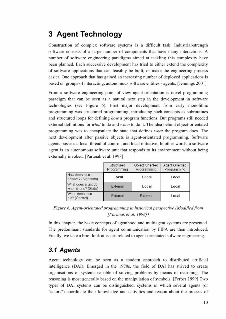
From a software engineering point of view agent-orientation is novel programming paradigm that can be seen as a natural next step in the development in software technologies (see Figure 6). First major development from early monolithic programming was structured programming, introducing such concepts as subroutines and structured loops for defining how a program functions. But programs still needed external definitions for what to do and when to do it. The idea behind object-orientated programming was to encapsulate the state that defines what the program does. The next development after passive objects is agent-orientated programming. Software agents possess a local thread of control, and local initiative. In other words, a software agent is an autonomous software unit that responds to its environment without being externally invoked. [Parunak et al. 1998]
Figure 6. Agent-orientated programming in historical perspective (Modified from [Parunak et al. 1998])
In this chapter, the basic concepts of agenthood and multiagent systems are presented. The predominant standards for agent communication by FIPA are then introduced. Finally, we take a brief look at issues related to agent-orientated sofware engineering.
3.1 Agents Agent technology can be seen as a modern approach to distributed artificial intelligence (DAI). Emerged in the 1970s, the field of DAI has strived to create organisations of systems capable of solving problems by means of reasoning. The reasoning is most generally based on the manipulation of symbols. [Ferber 1999] Two types of DAI systems can be distinguished: systems in which several agents (or "actors") coordinate their knowledge and activities and reason about the process of
10
coordination; and distributed problem solving in which the work of solving a problem is divided among a number of nodes that divide and share knowledge about the problem and the developing solution (e.g. blackboard systems). The modern concept of
rroundings. As a field of study, artificial life emerged in the late 1980s. [Ferber 1999]
others applications learning may be an
ment in order to meet its design objectives."
1. entifiable
2.
, a collection of
3. e designed to fulfill a specific purpose - they have particular goals to
4. eans that the agents have control over their internal state
5. ges in
ent in a timely fashion) and proactive (able to take initiative).
multiagent systems covers both of these types. [Weiss 1999]
The field of agent technology has also been influenced by the discipline of artificial life, which seeks to understand and model systems "possessing life"; capable of surviving, adapting and reproducing in sometimes hostile su
3.1.1 Definition of an agent
At present, there is no universally accepted definition of the term "agent". Autonomy is regarded to be essential to the idea of agenthood, but beyond this there is little consensus. Different emphasis on different domains gives rise to debate about other attributes. For example, in some applications the ability of agents to learn from experience is considered crucial, while in undesired phenomenon. [Wooldridge 1999]
However, a widely accepted definition is as follows: "An agent is an encapsulated computer system that is situated in some environment and that is capable of flexible, autonomous action in that environ[Jennings 2000] [Wooldridge 1997]
There are several points about this definition that we have to note:
The notion of encapsulation is used to express that agents are clearly idproblem solving entities, having well-defined boundaries and interfaces.
Agents are situated in an environment, receiving information of the state of the environment through sensors, and acting on the environment through effectors. The environment may be e.g. the physical world, a user via a GUIagents, the Internet, or a combination of these. [Wooldridge 1997]
Agents arachieve.
The notion of autonomy mand their own behaviour.
Agents are able to exhibit flexible problem solving in achieving their design objectives. Accordingly, the have to be both reactive (able to react to chantheir environm
[Jennings 2000]
Agent-oriented software engineering (or AOSE) is a research field concerned with engineering of software that has the concept of agents as its core computational abstraction. [Weiss 2002] However, some object-orientated programmers have not been able to see software agents as a new programming paradigm. Objects, being defined as computational entities that encapsulate some state and a collection of 11
methods for performing operations on this state, have apparent similarities to agents. Nonetheless, the most evident distinction between agents and objects is that in traditional object model there is a single thread of control, while in agent systems, each agent is inherently considered to have its own thread of control. Of course, Java constructs for multi-thread programming enable concurrent object programming. And furthermore, the idea of active objects enables objects to act without having their methods invoked by another object. Nevertheless, agents are capable of flexible (reactive and proactive) and autonomous (deciding for themselves whether or not to perform actions on request) behaviour. These kinds of features are beyond the object-orientated programming model. [Wooldridge 1999]
itecture makes specific comments about
ed to resemble the kind of practical reasoning we appear
n agent has about the world. Beliefs are
viding stability for decision making, and focusing an agent's practical
nal decomposition, indicating what kind be required in an agent.
r conceivable agent architectures can be found in [Wooldridge 1999] or [Ferber 1999].
3.1.2 The Belief-Desire-Intention Architecture
Essentially, an agent is characterised by the way it is designed (its architecture) and by its actions (behaviour). [Ferber 1999] The archthe internal structure and operation of agents.
The belief-desire-intention (BDI) architecture is one of the most successful agent theories. [Wooldridge 1997] It is based on the concept of human practical reasoning - the process of deciding, at each moment, which action to perform in order to reach our goals. Practical reasoning involves two important processes: deciding what goals we want to achieve, and how are we going to achieve those goals. The reasoning process of a BDI agent is thus intendto use in our everyday lives.
As suggested by the name, the internal state of a BDI agent is represented by three key data structures, which are intended to symbolise beliefs, desires and intentions. Beliefs are intended to represent the information atypically presented symbolically as "facts".
Desires may be seen as the tasks allocated to an agent. An agent may not be able to achieve all its desires, and desires may even be contradictory. Intentions are then used to represent the long-term goals of an agent, a fixed subset of the desires it has committed to achieving. These intentions will then feedback into the agent's future reasoning. An agent should be devoted to its long-term goals, and not adopt new intentions that contradict current intentions. Intentions play a central role in the BDI model, proreasoning.
The BDI model is attractive for evident reasons. First, the practical reasoning process is intuitive. Second, it provides a clear functioof subsystems might
[Wooldridge 1999]
Besides BDI, othe
12
3.2 Multiagent systems
3.2.1 Rationale of multi-agent approaches
While there are situations, in which an individual agent can by itself operate usefully, it is evident that most real world problems require multiple agents. Multi-agent systems (MAS) are needed to represent the decentralised nature of the problem, competing interests, or multiple perspectives.
In multiagent systems, the agents will have to interact with one another, either to achieve their individual goals, or to cope with the dependencies that arise from being situated in the same environment. The interaction may be just simple information exchange (using traditional client-server methods), or rich social interaction, enabling cooperation on and negotiation about actions to be performed.
Whatever the level of interaction may be, two definite distinctions between the agent-based approach and other software engineering paradigms are:
• Agent-based interaction takes place at the knowledge level. Instead of calling functions or invoking methods on a syntactic level, agents interact by human-like actions of requests, suggestions, commitments, and replies regarding goals to be achieved.
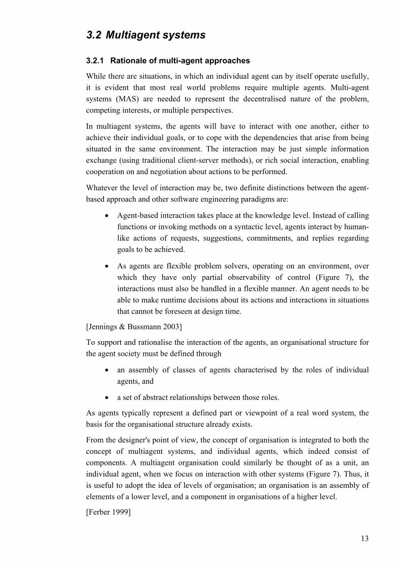
• As agents are flexible problem solvers, operating on an environment, over which they have only partial observability of control (Figure 7), the interactions must also be handled in a flexible manner. An agent needs to be able to make runtime decisions about its actions and interactions in situations that cannot be foreseen at design time.
[Jennings & Bussmann 2003]
To support and rationalise the interaction of the agents, an organisational structure for the agent society must be defined through
• an assembly of classes of agents characterised by the roles of individual agents, and
• a set of abstract relationships between those roles.
As agents typically represent a defined part or viewpoint of a real word system, the basis for the organisational structure already exists.
From the designer's point of view, the concept of organisation is integrated to both the concept of multiagent systems, and individual agents, which indeed consist of components. A multiagent organisation could similarly be thought of as a unit, an individual agent, when we focus on interaction with other systems (Figure 7). Thus, it is useful to adopt the idea of levels of organisation; an organisation is an assembly of elements of a lower level, and a component in organisations of a higher level.
[Ferber 1999]
13
Figure 7. A model of a multi-agent system with several hierarchical levels of organisation (Modified from [Jennings & Bussmann 2003])
It is evident that a multiagent-based approach does not likely yield an optimised system. It is hard to prove that agent-based solutions are even reliable. However, an optimal solution is not even the intention. Distributed systems are easier to understand and develop, when the problem to be solved is in itself distributed.
Current information systems are large and complex, and the massive amount of information is distributed and heterogeneous. The topology of the systems is dynamic, and the content is changing rapidly. The four major techniques for tackling these challenges are modularity, distribution, abstraction, and intelligence (i.e. using refined methods for information retrieval and processing). All of these techniques are combined in the multiagent-based approach. [Huhns & Stephens 1999]
To sum up, the advantages of interacting societies of agents are:
• cooperation in problem solving,
• representation of different interests or perspectives,
• sharing of expertise,
• working in parallel on common problems,
• modular and flexible development and reconfiguration of the system,
• fault tolerancy achieved through redundancy, and
• reuse.
[Huhns & Stephens 1999]
14
3.2.2 Agent communication
Agent messaging is based on speech act theory, which is a popular basis for analysing human communication. Speech act theory views human natural language as actions, such as requests, suggestions, commitments and replies. Such action is referred to as a speech act. The intended meaning of a speech act is referred to as a performative. Exemplar performatives are promise, report, tell, request, and demand. The perfomative thus defines clearly the meaning of the communication act, constraining its semantics. This greatly simplifies the design of the agents. [Ferber 1999] [Huhns & Stephens 1999]
Agent conversations consist of series of messages. To maintain globally coherent agent performance, several interaction protocols have been devised for groups of agents. An interaction protocol defines a structured exchange of messages that respond to the above-mentioned speech acts. An interaction protocol commonly used in distributed tasks is the contract net protocol. Consisting of cycles of announces, bids, and awards, the contract net protocol is modelled on the mechanisms used by businesses to govern the exchange of goods and services. Other typical interaction protocols support e.g. coordination, cooperation, or negotiation. [Huhns & Stephens 1999] Common agent communication languages enable diverse agent-to-agent
FIPA ACL and KQML define the semantics of the domain-independent
An ontology is a formal specification of shared concepts. To enable successful
Formed in 1996, The Foundation for Intelligent Physical Agents (FIPA) is an
communication across networks of agents. The agent communication languages with the broadest uptake are FIPA ACL, and KQML (Knowledge Query and Manipulation Language). [Luck et al. 2003] Many aspects of the KQML are incorporated in FIPA ACL. The FIPA organisation, standards, and the FIPA ACL are introduced in the following section.
communication protocol that should be shared universally by all agents. [Huhns & Stephens 1999] The domain-dependent semantics of the enclosed message is expressed in an ontology. The actual message content can be expressed in any language suitable for the application.
knowledge-level communication in a distributed environment, conventions on the content of shared knowledge are necessary. Ontologies and their role in agent communication are discussed in more detail in Chapter 4.
3.3 FIPA specifications
international non-profit organisation aimed at producing software standards for heterogeneous and interacting agents and agent-based systems. The standardisation effort is represented as a collection of FIPA specifications, defining agent communication languages, and protocols for message transport and agent interaction. [FIPA]
15
3.3.1 FIPA agent architecture
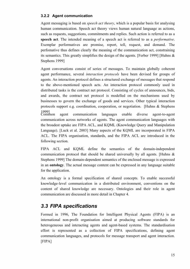
The FIPA agent management reference model [FIPA 2002a] defines the framework in t ribing agent creation, registration, communication, which he FIPA agents operate, desc
migration and retirement. The model (Figure 8) is only a logical reference, and does not imply any kind of design choice or implementation detail.
The logical com odel each represent a capability
s of the machines (one or more host computers), the
• iguously within
• ol over access to a use of the AP. The AMS maintain a
• ectory Facilitator (DF) is an optional component of the AP. It provides yellow pages services to other agents. Agents may advertise their
Figure 8. FIPA agent management reference model [FIPA 2002a]
ponents of the agent management reference m set (e.g. a service):
• An Agent Platform (AP) provides the infrastructure in which agents can be deployed. It consistoperating system, agent support software, FIPA agent management components, and the agents themselves. Internal design is an issue for agent system developers, as FIPA specifications are only concerned with communication between agents native to and outside the AP.
An agent is a fundamental actor on an AP. Each FIPA agent is identified with an Agent Identifier (AID) label, distinguishing it unambthe Agent Universe.
An Agent Management System (AMS) (a mandatory component of the AP) has supervisory contrdirectory of AIDs for agents registered with its AP, offering white pages services to other agents. Each agent must register with an AMS to get a valid AID.
A Dir
16
services with the DF, or query the DF to seek services offered by other agents. As opposed to AMS, there may be multiple DFs within an AP.
A Message Transport Service (MTS) is the default method for communication among agents on different Agent Platforms.
•
[FIPA 0
gent communication
FIPA agents communicate with one another by sending messages. Three fundamental namely the message structure, message
2 02a]
3.3.2 FIPA a
aspects of message communication, representation, and message transport, are concerned with by the FIPA specifications.
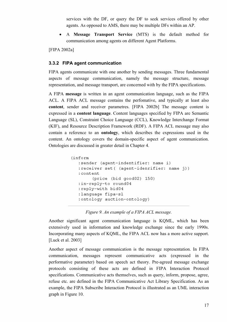
A FIPA message is written in an agent communication language, such as the FIPA ACL. A FIPA ACL message contains the perfomative, and typically at least alsocontent, sender and receiver parametres. [FIPA 2002b] The message content is expressed in a content language. Content languages specified by FIPA are Semantic Language (SL), Constraint Choice Language (CCL), Knowledge Interchange Format (KIF), and Resource Description Framework (RDF). A FIPA ACL message may also contain a reference to an ontology, which describes the expressions used in the content. An ontology covers the domain-specific aspect of agent communication. Ontologies are discussed in greater detail in Chapter 4.
Figure 9. An example of a FIPA ACL message.
Another significant agent communication language is KQML, which has been extensively used i the early 1990s.
essages represent communicative acts (expressed in the
n information and knowledge exchange sinceIncorporating many aspects of KQML, the FIPA ACL now has a more active support. [Luck et al. 2003]
Another aspect of message communication is the message representation. In FIPA communication, mperformative parameter) based on speech act theory. Pre-agreed message exchange protocols consisting of these acts are defined in FIPA Interaction Protocol specifications. Communicative acts themselves, such as query, inform, propose, agree, refuse etc. are defined in the FIPA Communicative Act Library Specification. As an example, the FIPA Subscribe Interaction Protocol is illustrated as an UML interaction graph in Figure 10.
17

Figure 10. FIPA Subscribe Interaction Protocol specifies the exchange of messages between agents in a subscription scenario. [FIPA 2002c]
T dealt with by ort Protocols
ntated software engineering The growing number of agent-based systems highlights the demand for software
e field of agent-
s for programming and communication. Still, most
A precise look at methods for agent-orientated software engineering is provided in The Agent Technology Roadmap [Luck et al. 2003] provided by the
he third aspect of message communication, namely the issue of message transport, isthe FIPA Agent Message Transport specifications. Transp
specified by FIPA are Hypertext Transfer Protocol (HTTP), Internet Inter-ORB Protocol (IIOP), and Wireless Application Protocol (WAP).
[FIPA 2002a] [FIPA]
3.4 Agent-orie
engineering technology tailored for these systems. Work on thorientated software engineering (AOSE) is not only concerned with development activities, but covers all phases from requirements engineering to maintenance. This work benefits from the software and knowledge engineering communities, and one of the main goals is to determine, to what extent general software engineering techniques can be applied to agent systems.
So far, work on AOSE has mostly been focused on analysis and design methods, development tools, and languageavailable approaches are largely at prototype stage, characterised by a lack of systematical testing. AOSE is a young, rapidly evolving, interdisciplinary field that has not yet settled on commonly accepted evaluation methods, techniques, and tools.
[Weiss 2002]
[Weiss 2002]. AgentLink Community also contains a comprehensive review of state-of-the-art
18
technologies. A thorough investigation into tools and products for MAS development can be found in [Mangina 2002] or [AgentLink].
3.4.1 Agent software development tools
called an agent platform. A typical
orm implementations,
[Vrba 2003]
By far, the most popular agent platform at the moment is JADE. [Agentcities 2003] A
Current systems for knowledge management have significant weaknesses:
• Searching information. Searches based on keywords can retrieve irrelevant
• Extracting information. Computer systems do not possess the common
• Maintenance. When weakly structured text sources grow large, keeping
help in e.g. detecting anomalies.
A software tool for agent development is often state-of-the-art agent platform consists of Java libraries for specification and development of user agent classes with specific attributes and behaviours. Usually the platform also provides a Java-based runtime environment, which ensures agent message exchange, registration, and service matching. The platform might also contain other tools, e.g. a graphical viewer of runtime agent messaging.
To ensure the interoperability of agents, even on different platfcompliancy with the FIPA standards has been recognised as a crucial property of agent platforms. A list of platforms that conform to the FIPA specifications can be found in [FIPA]. Of these, the most interesting within our research are the popular open-source platforms JADE, FIPA-OS and ZEUS. The commercial JACK platform is also of some interest, since it contains a full implementation of the belief-desire-intention model.
good benchmark evaluation of the more popular Java-based agent platforms can be found in [Vrba 2003]. [Mangina 2002] and [AgentLink] contain a comprehensive list of available platforms.
4 Ontologies in Information Processing
information that includes certain terms in different meanings. Equally, they miss information when different terms with the same meaning about the desired content are used. Also, otherwise isolated information could be put into a meaningful context, if the interrelationships between pieces of information could be exploited.
sense of humans, which enables us to extract relevant information from diverse information sources. Agents cannot retrieve information from textual representations, nor can they integrate information distributed over different sources.
them consistent, correct and up-to-date becomes difficult and time-consuming. Mechanised representations of semantics and constraints would
19

Ontologiknowledge sharing and reuse. Since the early 1990's, they have become a popular
ogies
ontology
Ontologies are developed to provide a machine-processable semantics of information between different agents, software or human.
efines the objects, concepts, and other entities of the domain of
epts used and the constraints on their use are
istinguished:
ain)
•ontologies, see section
• concepts for e.g. time, space, state or event.
•stating what should be represented, i.e. not committing to any particular
es were developed in artificial intelligence research community to facilitate
research topic. The use of ontologies has become widespread in such fields as intelligent information integration, cooperative information systems and electronic commerce. The use of ontologies and ontology tools offers a promising possibility to considerably improve knowledge management capabilities.
[Fensel 2001]
4.1 Ontol
4.1.1 Definition of an
sources that can be communicated Originally, ontology is a word borrowed from philosophy, where ontological theories attempt to describe everything that exists. Many definitions of ontologies have been given; the popular definition presented here is adopted from [Fensel 2001] and based on [Gruber 1993].
A formal representation of knowledge is based on a conceptualisation. A conseptualisation dinterest, and the relationships that exist between them. It is an abstract, simplified view of a domain. Every knowledge-based system is explicitly or implicitly committed to some conceptualisation. [Gruber 1993]
An ontology is a formal, explicit specification of a shared conceptualisation. "Explicit" means that the type of concdefined explicitly. "Formal" means that the ontology should be machine processable. "Shared" refers to the fact that an ontology captures consensual knowledge. An ontology is not restricted to an individual, but accepted by a group that commits to a common ontology. Summing up, an ontology provides a vocabulary of terms and relations with which to model its domain.
Different types of ontologies may be identified, depending on level of their generality. Among others, the following types can be d
• Domain ontologies capture the knowledge related to a particular type of domain (e.g. process automation or medical dom
Metadata ontologies provide a vocabulary for describing the content of on-line information resources (e.g. the Semantic Web 4.2)
Generic ontologies capture common knowledge about the world, providing basic
Representational ontologies provide representational entities without
20

domain. (A well-known representational ontology is the Frame Ontology [Gruber 1993], which defines concepts such as frames, slots, and slot constraints for frame-based knowledge expression.)
Method and task ontologies provide a reasoning point of view on domain knowledge, defining terms related to particular reaso
• ning tasks or methods.
[Fens
gies and knowledge management
Knowledge Management is concerned with acquiring, maintaining, and accessing tain large intranets containing
eneous information.
mon understanding of a domain, which can be communicated between applications and people. Thus, they have the potential to be
t in the near future the development of ontology languages (see section 4.2) will allow structural and semantic definitions of information, providing
instead of keyword matching; as the meaning of the information is presented in a machine-processable form, computers will be
• le automated reasoning over information, masses of distributed data can be
To summ owledge of a knowledge-based system. As an ontology provides an explicit conseptualisation of knowledge, its function may seem similar to that of a database schema. The differences, however, are:
el 2001]
4.1.2 Ontolo
knowledge of an organisation. Modern companies mainmassive amounts of information in mostly weakly structured electronic media, which can be textual, visual or even audible. Large quantities of distributed raw information are by themselves of little use to a company. Turning the rapidly increasing volumes of information into useful knowledge has become a major problem.
For dealing with the expanding amount of information, there has been progress in the development of technologies for uniform access to heterogInteroperatable representation languages (mainly XML) and common interfaces (such as ODBC) serve as examples of the progress. For successful knowledge-based communication, however, it is also necessary to establish a specification of the content of shared knowledge. [Gruber 1993]
Ontologies provide a shared and com
the solution to specification of common and shared knowledge. As the current WWW is the main technology for on-line information exchange, the utilisation of ontologies for knowledge representation is already underway within the Semantic Web activities (see section 4.2).
It is expected tha
completely new possibilities:
• Intelligent searches
able to fuse the relevant information from isolated, heterogeneous sources.
Query answering instead of information retrieval; as ontologies enab
refined into knowledge on a higher level. For example, an automation system could answer in a human fashion to a simple question: "How has the controlled process been behaving recently?".
arise, ontologies describe the static domain kn
21
• A language for defining ontologies is synthetically and semantically richer than common languages for database schemas.
• The information described in an ontology consists of semi-structured natural language texts, instead of data tables.
An ontology must be a shared and consensual • terminology, since it is used
• An ontology provides a domain theory, while a database schema is a mere
[Fensel 2
4.1.3 G
ple ontologies presented here are WordNet and KACTUS. WordNet is included because of its popularity, while KACTUS has been of particular interest
amples, the reader should see e.g. [Fensel 2001].
rmal
rinceton University, WordNet is an on-line lexical reference system for the English language. [WordNet] It contains
000 concepts organised in a taxonomy. The words are divided into
owledge About Complex Technical systems for multiple USe) is a European ESPRIT research project, focused on the development of explicitly
nowledge bases, i.e. ontologies, about technical systems during their life-
imary ontologies, describing distinguished parts of the world, and secondary
for information sharing and exchange.
structure definition of a data container.
001]
eneric ontologies
The two exam
within our research. For more ex
Like many ontologies used currently, WordNet and KACTUS actually have their semantics described in a form of a textual description. The lack of expressive formal definitions limits the possibilities for automatic reasoning. Research on fodefinitions of semantics is introduced in section 4.2.
WordNet
Developed by the Cognitive Science Laboratory at P
around 100categories of nouns, verbs, adjectives, adverbs and functions. Within each category, the words are organised by concepts and semantical relationships (e.g. synonymy).
The success of WordNet is based on the fact that it is (in addition to being available on-line and free of charge) a dictionary based on concepts, instead of being just an alphabetic list of words.
[Fensel 2001]
KACTUS
KACTUS (Kn
structured kcycle.
The KACTUS library of ontologies [KACTUS] contains three types of ontologies: generic, domain, and basic technical ontologies. The available ontologies are divided into prontologies, describing distinctions, typologies and theories that can be applied to the primary objects.
22
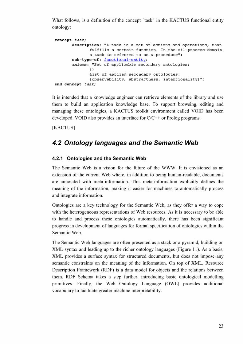
What follows, is a definition of the concept "task" in the KACTUS functional entity ontology:
It is intended that a knowledge engineer can retrieve elements of the library and use them to build an application knowledge base. To support browsing, editing and managing these ontologies, a KACTUS toolkit environment called VOID has been developed. VOID also provides an interface for C/C++ or Prolog programs.
[KACTUS]
4.2 Ontology languages and the Semantic Web
The Semantic Web is a vision for the future of the WWW. It is envisioned as an to being human-readable, documents
resentations of Web resources. As it is necessary to be able
leading up to the richer ontology languages (Figure 11). As a basis,
4.2.1 Ontologies and the Semantic Web
extension of the current Web where, in additionare annotated with meta-information. This meta-information explicitly defines the meaning of the information, making it easier for machines to automatically process and integrate information.
Ontologies are a key technology for the Semantic Web, as they offer a way to cope with the heterogeneous repto handle and process these ontologies automatically, there has been significant progress in development of languages for formal specification of ontologies within the Semantic Web.
The Semantic Web languages are often presented as a stack or a pyramid, building on XML syntax andXML provides a surface syntax for structured documents, but does not impose any semantic constraints on the meaning of the information. On top of XML, Resource Description Framework (RDF) is a data model for objects and the relations between them. RDF Schema takes a step further, introducing basic ontological modelling primitives. Finally, the Web Ontology Language (OWL) provides additional vocabulary to facilitate greater machine interpretability.
23

Figure 11. Semantic Web languages build on XML syntax. RDF and RDF Schema provide vocabulary for describing objects and relations between them. Ontology
languages such as OWL introduce additional vocabulary for ontological modelling. [Herman 2004]
OWL has been designed by the World Wide Web Consortium on the experience gained from its predecessors OIL and DAML+OIL. As of February 2004, OWL is a W3C Recommendation (i.e. standard) for publishing and sharing ontologies.
For more information on the Semantic Web, the reader should see [W3C].
[W3C] [Davies et al. 2003]
4.2.2 RDF
The Resource Description Framework (RDF) is a data model for objects ("resources") and the relations between them. It provides a simple semantics for this data model, and these data models can be represented in XML syntax.
Figure 12. A graph of an example RDF triple.
The basic building block in RDF is an object-attribute-value triple. A triple may be viewed as a directed labeled graph (Figure 12) or written in attribute(object, value) -format.
RDF uses XML as its serialisation syntax. The triple presented in Figure 12, with a type indication supported by RDF added, would look as follows:
24
<rdf:Description rdf:about=
"http://www.books.org/ISBN02622320030">
<hasAuthor rdf:resource="Gerhard Weiss"/>
<rdf:type rdf:resource=
"http://description.org/schema/book"/>
</rdf:Description>
It is important to note that RDF only provides a basic data model for meta-data. RDF does not reserve any terms for further data modelling, and neither does it provide any mechanisms for declaring property names to be used.
[W3C] [Fensel et al. 2003]
4.2.3 RDF Schema
RDF Schema (RDFS) proceeds to a richer representation formalism and introduces basic ontological modelling primitives. RDFS provides a vocabulary for describing properties and classes of RDF resources, with a semantics for hierarchies of these properties and classes. RDFS also lets developers define a particular vocabulary for RDF data attributes, and specify to which kind of objects these attributes can be applied.
RDFS uses predefined terms to provide a basic type system for models:
• Class and subClassOf for defining class structures
• subPropertyOf, domain and range for describing properties and hierarchies of properties
RDF Schema may be regarded as a very simple ontology language. However, many types of knowledge cannot be expressed with the limited vocabulary provided by RDFS.
As a footnote, FIPA RDF Content Language Specification defines how RDF can be used as the content language of a FIPA message. The specification presents modular RDF extensions, based on RDF Schemas. These extensions are intended to tackle representation of e.g. objects, propositions, actions, and rules. [FIPA 2001b]
[Fensel et al. 2003] [W3C]
4.2.4 OWL
The Web Ontology Language (OWL) has more facilities for expressing meaning and semantics than XML, RDF, and RDFS. Thus, OWL goes beyond these languages in its ability to represent machine interpretable knowledge. To be more exact, in comparison to its predecessor DAML+OIL and RDF, OWL adds more vocabulary for describing properties and classes: among others, relations between classes (e.g. unions, intersections), cardinality, equality, richer typing of properties, characteristics of properties (e.g. symmetry, transitivity), and enumerated classes. [W3C 2004]
25
OWL provides three increasingly expressive sublanguages for use by specific implementers and users. OWL Lite provides the basic definitions for a classification hierarchy and simple constrains. OWL DL provides all the OWL language constructs, while guaranteeing that all conclusions are computable. This means that the constructs can only be used under certain restrictions. (For example, a class cannot be an instance of another class.) OWL Full enables maximum expressiveness, but with no computational guarantees. Each of these sublanguages is an extension of its simpler predecessor, in the sense of what can be legally expressed and what can be validly concluded. [W3C 2004]
The universe according to OWL consists of the data type domain, described by the XML Schema [W3C] data types, and the object domain, described by the OWL classes. Every class element in OWL creates a subclass of owl:Class, and every object is a member of owl:Thing. Classes can be further refined by elements that include:
• rdfs:subClassOf
• owl:disjointWith and owl:sameClassAs
• s o , such as owl:intersectionOf,
• tie relations between elements of classes
The properties of classes can be either object properties (instances of
• rdfs:subPropertyOf
• rdfs:domain g that the property only applies to instances of the
• rdfs:range, asserting that the values of the property can only be instances
• rdfs:samePropertyAs
• owl:inverseOf owl:TransitiveProperty, owl:SymmetricProperty,
The class d by ties. Not
• owl:allValuesFrom, defining that all values for the property are of the
• owl:hasValue, defining a value that a property is required to have
boolean combination f class expressionsowl:unionOf or owl:complementOf
objects proper s, i.e. descriptions of
owl:ObjectProperty, relating objects to other objects), or data type properties (instances of owl:DatatypeProperty). As with classes, a property can be refined by the following elements:
, assertinspecified class
of the specified class
, owl:FunctionalProperty and owl:InverseFunctionalProperty
es can be even further refine restricting possible values of properrestricting the properties themselves, these restrictions can be defined by the following elements:
given class type, and owl:someValuesFrom, defining that at least one value for the property is of the given class type.
26
• owl:cardinality, owl:maxCardinality, and owl:minCardinality, which restrict the number of distinct values of the given property for a class
[Obitko & Mařík 2003] [W3C 2004]
4.3 Ontologies in agent systems
4.3.1 Ontologies in agent communication
As agents operate in a distributed environment, they negotiate and exchange knowledge. For successful knowledge-level communication, we need to establish conventions on three levels: representation language format, agent communication, and specification of the content of shared knowledge. Proposals for agent communication languages and standard knowledge representation formats (by e.g. FIPA) are independent of the content of the knowledge being communicated. For conventions of the third kind, content-specific specifications, ontologies can be used. [Gruber 1993] The clear separation of the domain-independent intent of a message, and the domain-
When a society of agents commits to common ontology, it also serves as a guarantee
The ontologies should naturally be well designed, meaning that they adequately
4.3.2 FIPA specification for ontologies in agent systems
According to FIPA, agents must share an ontology of their domain of application in
specific application aspects of a message, is a great advantage of multi-agent systems. The overall behaviour of the system is characterised in abstract terms by domain-neutral ACL performatives, forming patterns of interaction. When the characterisation of the application changes, only the component dealing with the domain-specific information, namely the ontology, must be changed. The separation thus provides adaptability. [Gibbins et al. 2004]
of consistency. A vocabulary for queries and assertions exchanged between agents is defined. For example, a planning ontology helps assure that an agent with planning capabilities is given the information needed for the planning task by the user of the agent. There is no guarantee that an agent can answer a query, but a commitment to common ontology makes sure that the queries and assertions are understood. However, a commitment to the form of content of internal knowledge to the agent is not necessary. [Gruber 1993]
capture the domain of the agents. In addition, the ontologies should be well defined, meaning that the semantics is defined formally. A formal description is necessary in order to enable automated reasoning over ontologies, making possible e.g. automatic ontology integration and sharing of different ontologies. Also, to enable shared ontologies needed in agent communication, the ontologies must be explicit. [Obitko & Mařík 2003]
order to have fruitful communication. The FIPA Ontology Specification [FIPA 2001a] (experimental at the time of writing) deals with technologies enabling agents to
27
manage ontologies. The specification defines an ontology service for a community of agents. The service is required to be provided by a dedicated agent, called an Ontology Agent, whose role is to provide some or all of the following services:
• discovery of and access to public ontologies
• maintenance of a set of public ontologies
• translation of expressions between different ontologies and/or content
• to queries for relationships between terms or between ontologies
•
Howe r ith the
owledge Base Connectivity (OKBC) as a basis for
[FIPA 2001a]
4.3.3 Semantic web ontology languages in agent ontologies
As discussed above, the need for explicit ontologies has been acknowledged by FIPA,
Expressing the semantics explicitly has the advantage of separating the semantics from
Moreover, OWL is built on XML and RDF syntax, which are both common and
[Obitko & Mařík 2003]
languages
responding
identifying a shared ontology for communication between two agents
ve , this (at the time still experimental) specification deals only wcommunicative interface to an ontology service while internal implementation and capabilities are left to developers.
The standard does define Open Knexpressing ontologies (referred in FIPA communication with the constant FIPA-Meta-Ontology), but OKBC is only intended to serve as an implicit interlingua for knowledge that is being communicated. It is intended that the designer may use any ontology language, and the translation of knowledge from the actual knowledge representation language into and out of this interlingua is left to the agents.
but so far there has been no proposal by FIPA for a practical ontology language. However, there has been much effort in the Semantic Web research community to develop semantically rich formal languages. It would therefore seem worthwhile to explore the possibilities to use the Semantic Web languages for modelling ontologies in multi-agent systems. The Web Ontology Language, introduced in section 4.2, provides an ontology modelling language with defined formal semantics.
the agent program code, thus making it easier to implement a mutual understanding for multi-agent societies. OWL provides a common language to define semantics, so that it can universally be understood.
widely adopted technologies. There already are tools available for processing OWL documents, and for reasoning over OWL ontologies. Also, many common XML or RDF tools can be used to work with OWL.
28
4.4 Ontologies in process automation
4.4.1 Working towards process automation ontologies
Process automation industry has traditionally been conservative in adopting novel technologies. The call for exchange and integration of a growing amount of information both within plants and between businesses has, however, yielded progress in knowledge management applications. As the integration and exchange of information demand a standardised format of information, there has been work on adapting state-of-the-art technologies, such as XML.
Nevertheless, constructing machine-processable ontologies for the domain is at present still an immense task. Work has to be practically started from scratch, as the conceptual models defined in the domain are in general not adequately formal in their representations, in order to be fruitfully utilised by agents.
As an ontology provides a common vocabulary of the terms and the relations of its domain [Fensel 2001], we first have to agree on a domain vocabulary, when constructing an ontology. Standardisation work on the domains of chemical processes and process automation provide established definitions of the concepts of the domain. Some conceptual models constructed also provide input for the definition of semantic relationships between the concepts. The industrial standards of these domains therefore provide a reasonable starting point for ontology development.
What can be obtained from these standards, is at least a well-defined terminology of the concepts of the domain. A few of these standards go on to define structured conceptual models. As the aim of the standards is to provide a way to exchange information, they seldom proceed to define formal descriptions, which would support automatic reasoning. However, as the attention is increasingly on interoperability with other systems, there is hope for future development in the direction of formal semantic definitions.
To ease the development of formal machine-processable ontologies, some work has already been done on specific domains related to process automation. In the following, we first explore industrial standards that provide input for ontologies in our domain, and then proceed to examine ontology-related development in the domain.
4.4.2 Industrial standards providing ground for ontologies
What follows is a list of industrial standards for process and process automation domain, which have been used as a starting point for development of a process automation ontology for the MUKAUTUVA project. Although many of the standards are of little benefit to our research, the concepts defined in them may likely be a basis for future conventions.
29
ISO 10303: the Standard for the Exchange of Product Model Data (STEP)
ISO 10303 is a standard for computer-interpretable representation and exchange of product data throughout the life cycle of a product. The aim is to define a mechanism for describing product data independent from any particular system. Part 221 of the standard, titled "Functional Data and Schematics Process Plants", is concerned with the functional and physical aspects of plant items. [ISO 1996] (Currently the standard is approved for submission as a draft international standard. [ISO])
The focus of the part 221 is on piping and instrumentation diagrams, and their representation in a computer sensible form. A thorough, partially generic glossary of plant systems and equipment is nevertheless presented. Unfortunately, process activities are outside the scope of the standard.
ANSI/ISA-95.00.01-2000: Control System Integration Part 1: Models and Terminology
The ISA-SP95 committee has published two standards of a series that will define the interfaces between enterprise activities and control activities. The first part of this standard describes the relevant functions in the enterprise and control domains, and which objects are exchanged between these domains. [ISA 2000]
The focus of the standard is heavily on integration of manufacturing and process control systems, keeping away from process control on a lower level. Interestingly though, the standard contains UML object models for information about products, production capabilities and production.
ISO 10628: Flow diagrams for process plants - General rules
This ISO standard establishes general rules for the preparation of flow diagrams for process plants. The aim is to simplify the exchange of information between different parties involved in different stages of the life cycle of a process plant. [ISO 1997]
Focusing mainly on diagrams, the standard provides only a basic vocabulary, describing quite roughly the physical structure and functions of a process plant.
IEC 61346: Industrial systems, installations and equipment and industrial products - Structuring principles and reference designations
The first part of the IEC 61346 standard (Part 1: Basic rules) deals with a reference designation system for identification of objects within a system or a plant during its life cycle. A reference designation identifies objects for correlation of information about objects among different documents. [SFS 2003]
The scope of the standard is quite wide, and the structuring principles presented are very general. It is however worthwhile to note that a well structured and standardised way to describe the system and the information about the system (as the standard suggests) would be an excellent starting point for creating a formal model (understood by agents) of a particular plant.
30
4.4.3 Examples of ontology-related work in the process automation domain
Below are few examples of formal conceptual information models developed recently in the process automation domain. What can be seen from (among others) these examples, is that XML and related technologies, such as XML Schema Definitions, are breaking through as the state-of-the-art technology in knowledge management in the process automation domain. However, these specifications are more concerned with the parametres of the information classes, than with semantically rich ontological definitions. Apparently, the aim is to produce XML models for current needs, while the mechanisms for utilising the models are of less concern.
PaperIXI Mill Model
PaperIXI is a development project supervised by Technology Industries of Finland, an interest group of approximately 1200 member companies. The project aims to develop exchange of technical information, such as technical specifications, safety instructions, descriptions of plant structure and functions, and operating and maintenance instructions, specifically in the domain of paper industry. The project emphasises company network collaboration and interoperation in the business processes where information is used or exchanged. [PaperIXI]
PaperIXI mill model is a hierarchical conceptual model, defining a functional structure for the maintenance, repair, and operation data of a paper mill. The model also pays attention to formal definition of relations between mill objects. [PaperIXI 2004]
The mill data model has been specified in UML class diagram format, and implemented in XML Schema. [PaperIXI 2004] Although the model is not to be considered semantically rich, it is nevertheless a formal conceptual data model of a process plant, and leading the way towards more sophisticated computer-processable models.
PSK Standards
The Finnish PSK Standards Association is a community of process industry and connected commercial enterprises, developing standards required in investments and maintenance of industrial plants. One of the aims is to define a common XML interface for information exchange.
PSK is organised in workgroups with different application domains. The most interesting standards of PSK to our research are standards 5960 to 5980, which are focused on XML communication and process plant modelling. The standards define a process mill model, and a set of mill object classes. The classes are defined using XML Schema format.
[PSK]
31

MIMOSA
MIMOSA is a not-for-profit trade association promoting the use of open information standards for operation and maintenance of commercial and military applications, e.g. process manufacturing corporations.
MIMOSA has released a specification for Open Systems Architecture for Enterprise Application Integration (OSA-EAI). The aim of OSA-EAI is to facilitate integration of asset management information from heterogeneous software applications. The OSA-EAI is constructed upon a common information schema, known as Common Relational Information Schema (CRIS), and presented XML Schema format. CRIS contains a terminology for describing sites, assets, services, and data models for standard measurements.
MIMOSA has gained attention and even spawned a few commercial products. It is however only a data schema, with little interest in describing the semantics of the information.
[MIMOSA]
WBF Batch Markup Language
The World Batch Forum (WBF) is a non-profit, professional organisation for promoting the exchange of information related to the management, operation and automation of batch process manufacturing.
WBF has developed a Batch Markup Language (BatchML), an implementation of the ANSI/ISA 88 family of standards for the batch processing industry. BatchML provides a set of element definitions that can be used for the representation of batch, master recipe, or equipment data. The definitions are expressed in XML Schema language.
[WBF]
5 Agent Technology in Information Processing
The need for information system integration has resulted in several low-level infrastructures providing interoperability between heterogeneous data sources and applications. This is however not enough for knowledge-level communication needed for sophisticated information exchange. Existing database systems also lack the support for any kind of proactive information discovery.
An advanced middleware infrastructure has been made possible with the paradigm of cooperative information systems. The approach is based on intelligent information agents that support higher levels of cooperation.
[Klusch 2001]
32
As stated in the preceding chapters, formal specifications on the content of the shared knowledge are necessary for successful knowledge-level communication. The aspects of agent-based communication enabling semantic information exchange, namely the message performative and the ontology, have already been covered in sections 3.2.2 and 4.3. Therefore, this chapter is focused on the roles and the coordination of agents in multiagent systems for information processing.
We begin by looking at the characteristics of cooperative information agents. Two exemplar information agent applications are then introduced. Finally, we explore the differences and mutual interests of Web Services technology and agent-based systems.
5.1 Characteristics of information agent systems Weiss [Weiss 1999] defines information agents as "agents that have access to multiple, potentially heterogeneous and geographically distributed information sources." Information agents have to deal with the increasing complexity of modern information environments, ranging from relatively simple in-house information systems to large-scale systems like the Internet. "One of the main tasks of these agents is an active search for relevant information in non-local domain on behalf of their users or other agents. This includes retrieving, analysing, manipulating and integrating information available from different information sources." [Weiss 1999]
According to Klusch [Klusch 2001], an information agent is supposed to satisfy one or more of the following requirements:
• Information acquisition and management: It is able to provide a transparent access to one or many different information sources. Transparency refers to the fact that the user does not have to know how to connect to the information source, how the information is represented in the source (syntax and semantics), or what the syntax for information queries is. Information is retrieved, extracted, filtered and monitored by the agent. The acquisition of information encompasses a broad range of scenarios including possibly even the purchase of relevant information from electronic marketplaces on behalf of the users.
• Information synthesis and presentation: The agent is able to combine heterogeneous data and to provide a coherent view on information relevant to the user.
• Intelligent user assistance: The agent can dynamically adapt to changes in the information, the environment, or the user preferences.
[Klusch 2001]
Information agents can be categorised into several different classes, depending on whether they are e.g. adaptive, rational or mobile. One of the most important classifications is the distinction between non-cooperative and cooperative information agents. Here, we focus on cooperative information agents.
33

Many of the past cooperative information agent applications rely on the concept of wrapper and mediator agents (Figure 13). The wrapper agents are used to provide transparent access to heterogeneous data sources. The wrappers extract content from their individual sources, and perform appropriate data conversions to map the data into the common domain ontology.
The mediator agents decompose and execute the complex information queries, possibly locating the relevant sources with the help of a matchmaker or a broker agent. The partial responses obtained from the sources are then fused into uniform response by the mediators.
Figure 13. A cooperative information agent system typically contains types of wrapper and mediator agents to integrate information. [Klusch 2001]
Coordination is the process of managing dependencies between activities of one or more actors performed to achieve a goal and to avoid conflicts while having maximum concurrency. Coordination involves issues like task decomposition, resource allocation, synchronisation, and the preparation and adoption of common objectives. [Klusch 2001]
Several approaches to coordination in multi-agent environments have been introduced. Collaboration among information agents may be based on social obligations arising from common intentions, or delegation of tasks and responsibilities. Two common examples for coordination are based on techniques of service brokering and matchmaking (Figure 14).
In both approaches, provider agents advertise their capabilities for information processing to a matchmaker or a broker. A requester agent then sends a request for a information processing service to the matchmaker or the broker, which then matches its set of advertisements to the request.
34
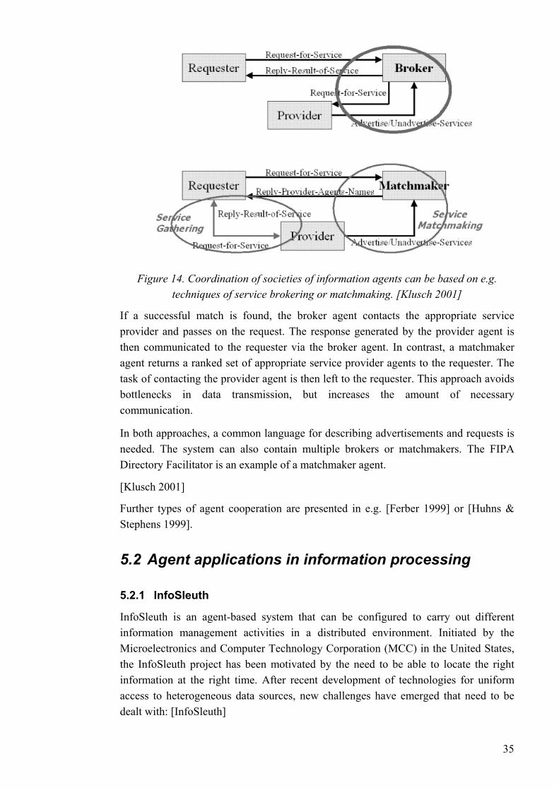
Figure 14. Coordination of societies of information agents can be based on e.g. techniques of service brokering or matchmaking. [Klusch 2001]
If a successful match is found, the broker agent contacts the appropriate service provider and passes on the request. The response generated by the provider agent is then communicated to the requester via the broker agent. In contrast, a matchmaker agent returns a ranked set of appropriate service provider agents to the requester. The task of contacting the provider agent is then left to the requester. This approach avoids bottlenecks in data transmission, but increases the amount of necessary communication.
In both approaches, a common language for describing advertisements and requests is needed. The system can also contain multiple brokers or matchmakers. The FIPA Directory Facilitator is an example of a matchmaker agent.
[Klusch 2001]
Further types of agent cooperation are presented in e.g. [Ferber 1999] or [Huhns & Stephens 1999].
5.2 Agent applications in information processing
5.2.1 InfoSleuth
InfoSleuth is an agent-based system that can be configured to carry out different information management activities in a distributed environment. Initiated by the Microelectronics and Computer Technology Corporation (MCC) in the United States, the InfoSleuth project has been motivated by the need to be able to locate the right information at the right time. After recent development of technologies for uniform access to heterogeneous data sources, new challenges have emerged that need to be dealt with: [InfoSleuth]
35
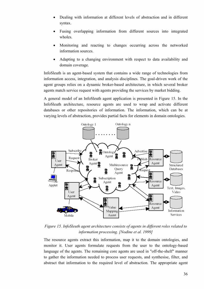
• Dealing with information at different levels of abstraction and in different syntax.
• Fusing overlapping information from different sources into integrated wholes.
• Monitoring and reacting to changes occurring across the networked information sources.
• Adapting to a changing environment with respect to data availability and domain coverage.
InfoSleuth is an agent-based system that contains a wide range of technologies from information access, integration, and analysis disciplines. The goal-driven work of the agent groups relies on a dynamic broker-based architecture, in which several broker agents match service request with agents providing the services by market bidding.
A general model of an InfoSleuth agent application is presented in Figure 15. In the InfoSleuth architecture, resource agents are used to wrap and activate different databases or other repositories of information. The information, which can be at varying levels of abstraction, provides partial facts for elements in domain ontologies.
Figure 15. InfoSleuth agent architecture consists of agents in different roles related to information processing. [Nodine et al. 1999]
The resource agents extract this information, map it to the domain ontologies, and monitor it. User agents formulate requests from the user to the ontology-based language of the agents. The remaining core agents are used in "off-the-shelf" manner to gather the information needed to process user requests, and synthesise, filter, and abstract that information to the required level of abstraction. The appropriate agent
36
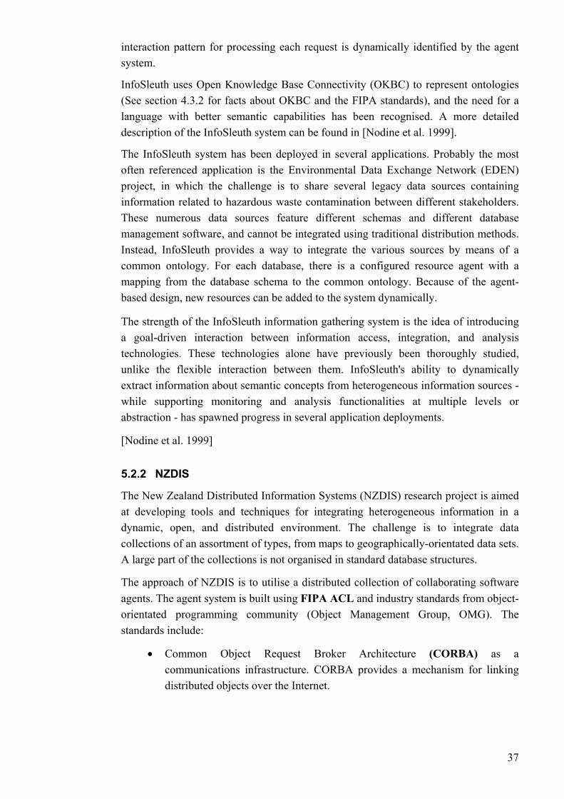
interaction pattern for processing each request is dynamically identified by the agent system.
InfoSleuth uses Open Knowledge Base Connectivity (OKBC) to represent ontologies (See section 4.3.2 for facts about OKBC and the FIPA standards), and the need for a language with better semantic capabilities has been recognised. A more detailed description of the InfoSleuth system can be found in [Nodine et al. 1999].
The InfoSleuth system has been deployed in several applications. Probably the most often referenced application is the Environmental Data Exchange Network (EDEN) project, in which the challenge is to share several legacy data sources containing information related to hazardous waste contamination between different stakeholders. These numerous data sources feature different schemas and different database management software, and cannot be integrated using traditional distribution methods. Instead, InfoSleuth provides a way to integrate the various sources by means of a common ontology. For each database, there is a configured resource agent with a mapping from the database schema to the common ontology. Because of the agent-based design, new resources can be added to the system dynamically.
The strength of the InfoSleuth information gathering system is the idea of introducing a goal-driven interaction between information access, integration, and analysis technologies. These technologies alone have previously been thoroughly studied, unlike the flexible interaction between them. InfoSleuth's ability to dynamically extract information about semantic concepts from heterogeneous information sources - while supporting monitoring and analysis functionalities at multiple levels or abstraction - has spawned progress in several application deployments.
[Nodine et al. 1999]
5.2.2 NZDIS
The New Zealand Distributed Information Systems (NZDIS) research project is aimed at developing tools and techniques for integrating heterogeneous information in a dynamic, open, and distributed environment. The challenge is to integrate data collections of an assortment of types, from maps to geographically-orientated data sets. A large part of the collections is not organised in standard database structures.
The approach of NZDIS is to utilise a distributed collection of collaborating software agents. The agent system is built using FIPA ACL and industry standards from object-orientated programming community (Object Management Group, OMG). The standards include:
• Common Object Request Broker Architecture (CORBA) as a communications infrastructure. CORBA provides a mechanism for linking distributed objects over the Internet.
37
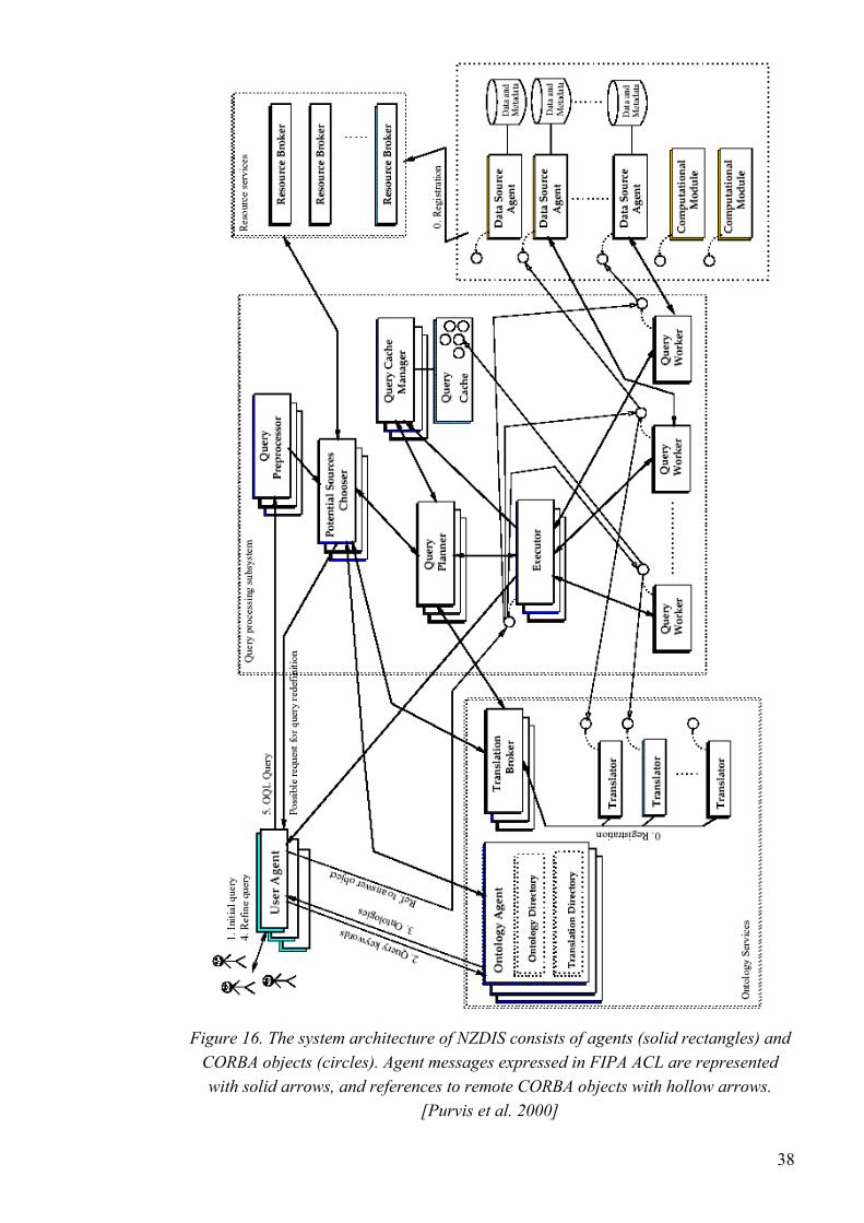
Figure 16. The system architecture of NZDIS consists of agents (solid rectangles) and CORBA objects (circles). Agent messages expressed in FIPA ACL are represented with solid arrows, and references to remote CORBA objects with hollow arrows.
[Purvis et al. 2000]
38
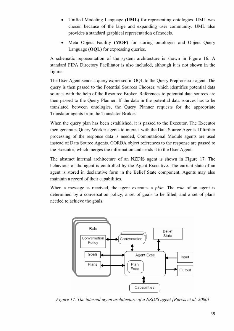
• Unified Modeling Language (UML) for representing ontologies. UML was chosen because of the large and expanding user community. UML also provides a standard graphical representation of models.
• Meta Object Facility (MOF) for storing ontologies and Object Query Language (OQL) for expressing queries.
A schematic representation of the system architecture is shown in Figure 16. A standard FIPA Directory Facilitator is also included, although it is not shown in the figure.
The User Agent sends a query expressed in OQL to the Query Preprocessor agent. The query is then passed to the Potential Sources Chooser, which identifies potential data sources with the help of the Resource Broker. References to potential data sources are then passed to the Query Planner. If the data in the potential data sources has to be translated between ontologies, the Query Planner requests for the appropriate Translator agents from the Translator Broker.
When the query plan has been established, it is passed to the Executor. The Executor then generates Query Worker agents to interact with the Data Source Agents. If further processing of the response data is needed, Computational Module agents are used instead of Data Source Agents. CORBA object references to the response are passed to the Executor, which merges the information and sends it to the User Agent.
The abstract internal architecture of an NZDIS agent is shown in Figure 17. The behaviour of the agent is controlled by the Agent Executive. The current state of an agent is stored in declarative form in the Belief State component. Agents may also maintain a record of their capabilities.
When a message is received, the agent executes a plan. The role of an agent is determined by a conversation policy, a set of goals to be filled, and a set of plans needed to achieve the goals.
Figure 17. The internal agent architecture of a NZDIS agent [Purvis et al. 2000]
39
The open NZDIS agent system can be used in tightly integrated database systems, or alternatively in systems distributed so widely that only Web-based information discovery techniques are feasible. The use of widely adopted object-orientated technology facilitates the adoption of the system in different applications.
[Purvis et al. 2000]
5.3 Web Services and agent-based systems Web Services is state-of-the-art technology that incorporates some of the characteristics of cooperative information agent systems. Therefore, we now take a brief look into the differences and mutual aspects between Web Services and information agents.
Web Services is a term that refers to the programmatic interfaces made available for application to application communication in the WWW. Because of the interoperability and extensibility of XML, Web Services can be combined in a loosely coupled way to achieve complex operations. [W3C 2002]
The world of Web Services consists of distributed systems that can adapt to changes with the help of service descriptions that enable opportunistic service discovery and reuse. Interactions not foreseen at design time can take place, as new services become available. Service discovery is based on advertising the service descriptions by means of e.g. matchmakers or directory services.
Although some of the technologies used for service discovery are more semantically rich than others, ontology definitions in the Web Services field have been more concerned with the signature of the services (the types of the parametres of the service) than with any form of ontological classification of the services.
Another distinction to the agent-based systems is that the common approaches do not provide a basis for defining the pragmatics of different message types. In other words, the intent of a message depends on the application domain. The separation between the domain-dependent and the domain-independent aspects of communication - as made in the world of multi-agent systems - would significantly reduce the brittleness of systems.
[Gibbins et al. 2004]
Web Services can be seen as an intermediate evolutionary step in systems development on the way to agent-based systems. A good evaluation of how the world of Web Services would benefit from adopting aspects of agent-based computing can be found in [Gibbins et al. 2004].
40
6 Agent Technology in Process Automation In this chapter, some of the few agent applications in the field of process automation are presented. Although the subject of the thesis is information agents, a few applications of agents that participate in process control activities are also included.
For further reading, general motivations for adopting agent-based methods to engineering of control systems can be found in [Jennings & Bussmann 2003]. In addition, [Parunak 1998] presents motivations for using agent technology in the industrial world, providing also a comprehensive list of practical and industrial applications.
6.1 Agent applications in process automation In the following, we introduce some of the current challenges in process automation that could be addressed by agent applications. After that, two information agent applications under development are briefly introduced.
Process monitoring and diagnostics
Demands for reliability and availability of automated processes call for sophisticated methods for performance monitoring and diagnostics. At current, users can define fixed alarm limits for individual measurements. However, the system should be able to monitor more abstract aspects of the process (e.g. a high-level definition of the state of a given process). Monitoring should also be automatically configured.
[Hammarström & Virta 2003] [Ventä 2003]
Early detection of slowly developing faults is necessary to ensure reliable production. The systems should also be able to present refined high-level information about occurred faults.
Some individual field devices already have applications for self-diagnostics. Nonetheless, determining the overall performance of the plant is still difficult, particularly if there are frequent process modifications.
To determine overall plant performance, automation systems should be able to determine the state of the system as a whole. However, the state of a complex system cannot be determined directly on the basis of individual measurements.
[Ventä 2003]
Measurement data processing
The increasing intelligence of field devices enables (soft) sensors to process the growing amounts of measurement data into refined knowledge. However, current automation systems for the most part only read raw measurement data. The refined information that can be produced by intelligent sensors is on a higher level of abstraction, and can not be utilised.
41
Sensor fusion would also enable more efficient measurements, but for it to work, sensors would have to be able to communicate with each other. At present, sensor
y be realised by establishing the logical connection between the sensors through the automation system.
[Ventä 2003]
& Virta 2003] An example of the current
in the process system can result in are triggered by distant consequences of the actual defect, leaving
the operator unaware of the origin of the problem.
n these situations, the automation system should be able to oblem (preferably in advance), and perform or suggest corrective
ands for process availability, insertion (and removal) of new evices or software components from different vendors should be easy and flexible.
chnology have been proposed. Table 1 shows how these applications relate to the challenges, and what has been general motivation for adopting the agent-based approach.
fusion can onl
Alarm handling
In a stable process state, an alarm about a even a slight deviation might be useful. However, in a critical situation, the resulting flood of alarms does not help, and may even confuse an operator. [Hammarströmlimited methods for alarm filtering is masking the non-critical alarms on the basis of hard-coded conditions. [MUKAUTUVA]
Alarm information should also be refined. The system should be able to identify the cause of a fault situation. [Ventä 2003] A defect many alarms that
Fault tolerance
Automation systems should be able to cope with unexpected situations, such as failure of process equipment, faults in control system hardware, or disturbances caused by process fluctuations. Iidentify the practions. [Ventä 2003]
Plug and play
Because of strict demd[Tommila et al. 2001]
To address the challenges presented in the above, process automation applications based on agent te
42
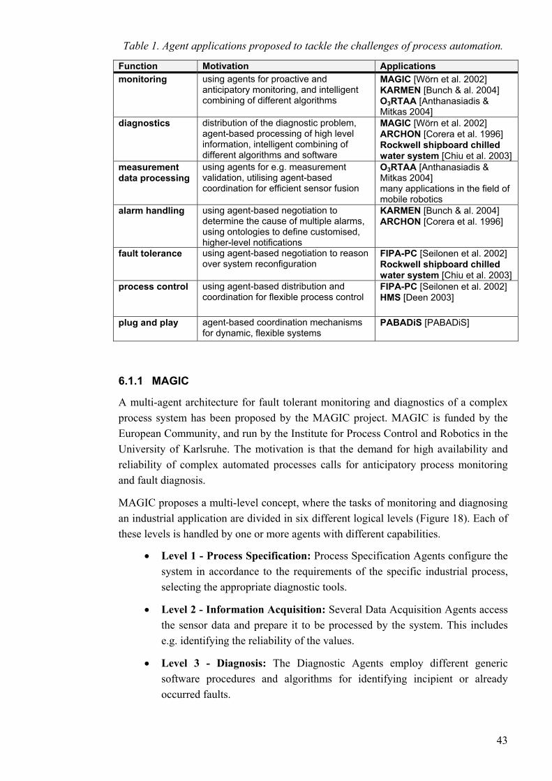
Table 1. Agent applications proposed to tackle the challenges of process automation.
Function Motivation Applications monitoring using agents for proactive and
anticipatory monitoring, and intelligent combining of different algorithms
MAGIC [Wörn et al. 2002] KARMEN [Bunch & al. 2004] O3RTAA [Anthanasiadis & Mitkas 2004]
diagnostics distribution of the diagnostic problem, agent-based processing of high level information, intelligent combining of different algorithms and software
MAGIC [Wörn et al. 2002] ARCHON [Corera et al. 1996] Rockwell shipboard chilled water system [Chiu et al. 2003]
measurement data processing
using agents for e.g. measurement validation, utilising agent-based coordination for efficient sensor fusion
O3RTAA [Anthanasiadis & Mitkas 2004] many applications in the field of mobile robotics
alarm handling using agent-based negotiation to determine the cause of multiple alarms, using ontologies to define customised, higher-level notifications
KARMEN [Bunch & al. 2004] ARCHON [Corera et al. 1996]
fault tolerance using agent-based negotiation to reason over system reconfiguration
FIPA-PC [Seilonen et al. 2002] Rockwell shipboard chilled water system [Chiu et al. 2003]
process control using agent-based distribution and coordination for flexible process control
FIPA-PC [Seilonen et al. 2002] HMS [Deen 2003]
plug and play agent-based coordination mechanisms for dynamic, flexible systems
PABADiS [PABADiS]
6.1.1 MAGIC
A multi-agent architecture for fault tolerant monitoring and diagnostics of a complex process system has been proposed by the MAGIC project. MAGIC is funded by the European Community, and run by the Institute for Process Control and Robotics in the University of Karlsruhe. The motivation is that the demand for high availability and reliability of complex automated processes calls for anticipatory process monitoring and fault diagnosis.
MAGIC proposes a multi-level concept, where the tasks of monitoring and diagnosing an industrial application are divided in six different logical levels (Figure 18). Each of these levels is handled by one or more agents with different capabilities.
• Level 1 - Process Specification: Process Specification Agents configure the system in accordance to the requirements of the specific industrial process, selecting the appropriate diagnostic tools.
• Level 2 - Information Acquisition: Several Data Acquisition Agents access the sensor data and prepare it to be processed by the system. This includes e.g. identifying the reliability of the values.
• Level 3 - Diagnosis: The Diagnostic Agents employ different generic software procedures and algorithms for identifying incipient or already occurred faults.
43
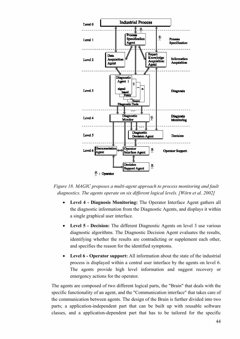
Figure 18. MAGIC proposes a multi-agent approach to process monitoring and fault diagnostics. The agents operate on six different logical levels. [Wörn et al. 2002]
• Level 4 - Diagnosis Monitoring: The Operator Interface Agent gathers all the diagnostic information from the Diagnostic Agents, and displays it within a single graphical user interface.
• Level 5 - Decision: The different Diagnostic Agents on level 3 use various diagnostic algorithms. The Diagnostic Decision Agent evaluates the results, identifying whether the results are contradicting or supplement each other, and specifies the reason for the identified symptoms.
• Level 6 - Operator support: All information about the state of the industrial process is displayed within a central user interface by the agents on level 6. The agents provide high level information and suggest recovery or emergency actions for the operator.
The agents are composed of two different logical parts, the "Brain" that deals with the specific functionality of an agent, and the "Communication interface" that takes care of the communication between agents. The design of the Brain is further divided into two parts; a application-independent part that can be built up with reusable software classes, and a application-dependent part that has to be tailored for the specific
44
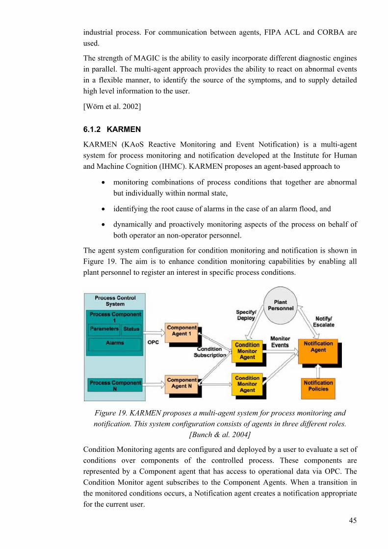
industrial process. For communication between agents, FIPA ACL and CORBA are used.
The strength of MAGIC is the ability to easily incorporate different diagnostic engines in parallel. The multi-agent approach provides the ability to react on abnormal events in a flexible manner, to identify the source of the symptoms, and to supply detailed high level information to the user.
[Wörn et al. 2002]
6.1.2 KARMEN
KARMEN (KAoS Reactive Monitoring and Event Notification) is a multi-agent system for process monitoring and notification developed at the Institute for Human and Machine Cognition (IHMC). KARMEN proposes an agent-based approach to
• monitoring combinations of process conditions that together are abnormal but individually within normal state,
• identifying the root cause of alarms in the case of an alarm flood, and
• dynamically and proactively monitoring aspects of the process on behalf of both operator an non-operator personnel.
The agent system configuration for condition monitoring and notification is shown in . The aim is to enhance condition monitoring capabilities by enabling all
plant personnel to register an interest in specific process conditions. Figure 19
Figure 19. KARMEN proposes a multi-agent system for process monitoring and notification. This system configuration consists of agents in three different roles.
[Bunch & al. 2004]
Condition Monitoring agents are configured and deployed by a user to evaluate a set of conditions over components of the controlled process. These components are represented by a Component agent that has access to operational data via OPC. The Condition Monitor agent subscribes to the Component Agents. When a transition in the monitored conditions occurs, a Notification agent creates a notification appropriate for the current user.
45

Much of the work on KARMEN has focused on the issue of notification policies. These policies represent organisational requirements and personal preferences. They define the actions to be taken when a monitored event occurs, and what the appropriate way to contact the user is. An interesting fact to our research is that the policy ontologies are expressed in OWL.
[Bunch & al. 2004]
6.2 Agent-based control applications Many of the agent applications in the domain of process automation deal with control activities. In the following, three interesting applications are introduced. We first go through the concepts of holonic manufacturing systems, and explore the mutual aspects of HMS and multiagent systems. The FIPA for Process Control (FIPA-PC) concept is also introduced, as it is the result of the preceding research project "Agent-augmented process automation system", and the basis of development for our information agent system. Finally, we look at the distributed control architecture for combat ships developed by Rockwell Automation.
Among these, the Plant Automation based on Distributed Systems [PABADiS] project, funded by the European Union, is also worth mentioning.
6.2.1 Holonic Manufacturing Systems
Holonic Manufacturing Systems (HMS) is a project of the Intelligent Manufacturing Systems (IMS) program. Holonic manufacturing system technology is a novel approach aimed at addressing manufacturing challenges such as tightening customer requirements (for customised, high-quality products with short order-to-delivery time) and increasing manufacturing systems complexity (systems are distributed, concurrent and stochastic). [Brennan & Norrie 2003]
The research topics of HMS and multiagent systems overlap strongly in the issues of communication protocols, reasoning, coordination and cooperation strategies, planning and scheduling. The main difference is that the HMS community has focused on the real-time end of the manufacturing process (low-level), as the MAS research aims to implement social behaviour of intelligent entities (high-level).
An HMS consists of autonomous manufacturing units called holons. By definition, a holon is "an autonomous and co-operative building block of a manufacturing system for transforming, transporting, storing and/or validating information and physical objects." [Brennan & Norrie 2003] The concept of holons was first introduced by philosopher Arthur Koestler in the late 1960s. Koestler used the term (derived from the Greek word 'holos' meaning whole, and suffix 'on' meaning a particle) to describe autonomous, cooperative entities in biological and social systems. [Gruver et al. 2004]
A holon is a building block of a manufacturing system with decentralised control. A holonic manufacturing system is constructed in a bottom-up fashion by integrating holons in such a way that they provide system-wide flexibility, robustness and 46
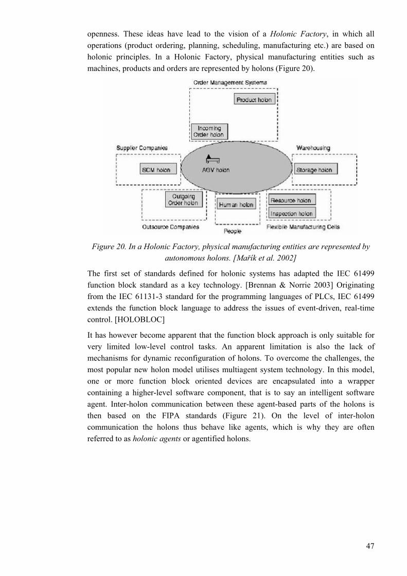
openness. These ideas have lead to the vision of a Holonic Factory, in which all operations (product ordering, planning, scheduling, manufacturing etc.) are based on holonic principles. In a Holonic Factory, physical manufacturing entities such as machines, products and orders are represented by holons (Figure 20).
Figure 20. In a Holonic Factory, physical manufacturing entities are represented by autonomous holons. [Mařík et al. 2002]
The first set of standards defined for holonic systems has adapted the IEC 61499 function block standard as a key technology. [Brennan & Norrie 2003] Originating from the IEC 61131-3 standard for the programming languages of PLCs, IEC 61499 extends the function block language to address the issues of event-driven, real-time control. [HOLOBLOC]
It has however become apparent that the function block approach is only suitable for very limited low-level control tasks. An apparent limitation is also the lack of mechanisms for dynamic reconfiguration of holons. To overcome the challenges, the most popular new holon model utilises multiagent system technology. In this model, one or more function block oriented devices are encapsulated into a wrapper containing a higher-level software component, that is to say an intelligent software agent. Inter-holon communication between these agent-based parts of the holons is then based on the FIPA standards ( ). On the level of inter-holon communication the holons thus behave like agents, which is why they are often referred to as holonic agents or agentified holons.
Figure 21
47

Figure 21. The new holon model uses FIPA standards for inter-holon communication. [Mařík et al. 2002]
On the other hand, as the MAS field has focused on information processing, with lack of access to control of physical entities, it could likely benefit from the results achieved in the HMS area. The problems related to real-time control, imposition of manufacturing and transportation constraints, limited and changing capacity have been more relevant in the HMS community. The mutual aspects of the two emerging fields are investigated in [Mařík et al. 2002] For information on recent development in HMS, the reader should see [Deen 2003].
[Mařík et al. 2002]
6.2.2 FIPA for Process Control
FIPA for Process Control (FIPA-PC) is an agent-augmented process automation system architecture developed at the Helsinki University of Technology.
According to the FIPA-PC concept, a process automation system extended with agents consists of two layers (Figure 22): a lower-lever layer of traditional real-time process automation system, and a higher-level agent layer. The agent layer is a society of cooperating supervisory subprocess agents. The primary function of the agent layer is to monitor the lower-level automation system and reconfigure its operation logic when needed. The agent layer is also used to cooperatively provide data from the process and the automation system to external clients.
Each subprocess agent supervises a defined part of the controlled process. The area of responsibility may relate to either a physical or a functional division of the process. The agents perform distributed run-time planning and execution of goal-orientated control sequences. Cooperative query processing and fault-recovery operations are carried out with market-based negotiation (e.g. FIPA Contract Net Interaction Protocol).
[Seilonen et al. 2002]
48
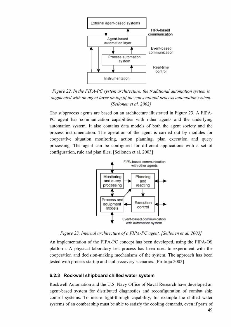
Figure 22. In the FIPA-PC system architecture, the traditional automation system is augmented with an agent layer on top of the conventional process automation system.
[Seilonen et al. 2002]
The subprocess agents are based on an architecture illustrated in Figure 23. A FIPA-PC agent has communication capabilities with other agents and the underlying automation system. It also contains data models of both the agent society and the process instrumentation. The operation of the agent is carried out by modules for cooperative situation monitoring, action planning, plan execution and query processing. The agent can be configured for different applications with a set of configuration, rule and plan files. [Seilonen et al. 2003]
Figure 23. Internal architecture of a FIPA-PC agent. [Seilonen et al. 2003]
An implementation of the FIPA-PC concept has been developed, using the FIPA-OS platform. A physical laboratory test process has been used to experiment with the cooperation and decision-making mechanisms of the system. The approach has been tested with process startup and fault-recovery scenarios. [Pirttioja 2002]
6.2.3 Rockwell shipboard chilled water system
49
Rockwell Automation and the U.S. Navy Office of Naval Research have developed an agent-based system for distributed diagnostics and reconfiguration of combat ship control systems. To insure fight-through capability, for example the chilled water systems of an combat ship must be able to satisfy the cooling demands, even if parts of
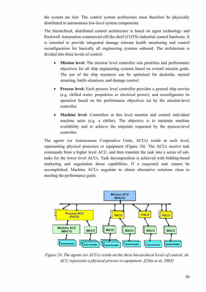
the system are lost. The control system architecture must therefore be physically distributed to autonomous low-level system components.
The hierarchical, distributed control architecture is based on agent technology and Rockwell Automation commercial-off-the-shelf (COTS) industrial control hardware. It is intended to provide integrated damage tolerant health monitoring and control reconfiguration for basically all engineering systems onboard. The architecture is divided into three levels of control:
• Mission level: The mission level controller sets priorities and performance objectives for all ship engineering systems based on overall mission goals. The use of the ship resources can be optimised for dockside, normal steaming, battle situations, and damage control.
• Process level: Each process level controller provides a general ship service (e.g. chilled water, propulsion or electrical power), and reconfigurates its operation based on the performance objectives set by the mission-level controller.
• Machine level: Controllers at this level monitor and control individual machine units (e.g. a chiller). The objective is to maintain machine availability and to achieve the setpoints requested by the process-level controller.
The agents (or Autonomous Cooperative Units, ACUs) reside at each level, representing physical processes or equipment (Figure 24). The ACUs receive task commands from a higher level ACU, and then translate the task into a series of sub-tasks for the lower level ACUs. Task decomposition is achieved with bidding-based marketing and negotiation about capabilities. If a requested task cannot be accomplished, Machine ACUs negotiate to obtain alternative solutions close to meeting the performance goals.
Figure 24. The agents (or ACUs) reside on the three hierarchical levels of control. An ACU represents a physical process or equipment. [Chiu et al. 2003]
50
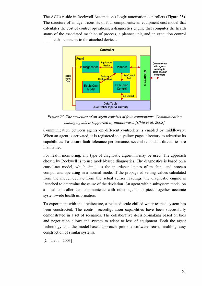
The ACUs reside in Rockwell Automation's Logix automation controllers (Figure 25). The structure of an agent consists of four components: an equipment cost model that calculates the cost of control operations, a diagnostics engine that computes the health status of the associated machine of process, a planner unit, and an execution control module that connects to the attached devices.
Figure 25. The structure of an agent consists of four components. Communication among agents is supported by middleware. [Chiu et al. 2003]
Communication between agents on different controllers is enabled by middleware. When an agent is activated, it is registered to a yellow pages directory to advertise its capabilities. To ensure fault tolerance performance, several redundant directories are maintained.
For health monitoring, any type of diagnostic algorithm may be used. The approach chosen by Rockwell is to use model-based diagnostics. The diagnostics is based on a causal-net model, which simulates the interdependencies of machine and process components operating in a normal mode. If the propagated setting values calculated from the model deviate from the actual sensor readings, the diagnostic engine is launched to determine the cause of the deviation. An agent with a subsystem model on a local controller can communicate with other agents to piece together accurate system-wide health information.
To experiment with the architecture, a reduced-scale chilled water testbed system has been constructed. The control reconfiguration capabilities have been successfully demonstrated in a set of scenarios. The collaborative decision-making based on bids and negotiation allows the system to adapt to loss of equipment. Both the agent technology and the model-based approach promote software reuse, enabling easy construction of similar systems.
[Chiu et al. 2003]
51
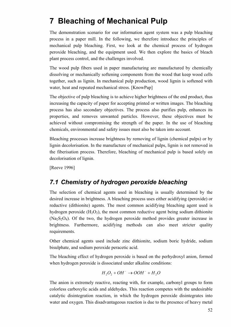
7 Bleaching of Mechanical Pulp The demonstration scenario for our information agent system was a pulp bleaching process in a paper mill. In the following, we therefore introduce the principles of mechanical pulp bleaching. First, we look at the chemical process of hydrogen peroxide bleaching, and the equipment used. We then explore the basics of bleach plant process control, and the challenges involved.
The wood pulp fibers used in paper manufacturing are manufactured by chemically dissolving or mechanically softening components from the wood that keep wood cells together, such as lignin. In mechanical pulp production, wood lignin is softened with water, heat and repeated mechanical stress. [KnowPap]
The objective of pulp bleaching is to achieve higher brightness of the end product, thus increasing the capacity of paper for accepting printed or written images. The bleaching process has also secondary objectives. The process also purifies pulp, enhances its properties, and removes unwanted particles. However, these objectives must be achieved without compromising the strength of the paper. In the use of bleaching chemicals, environmental and safety issues must also be taken into account.
Bleaching processes increase brightness by removing of lignin (chemical pulps) or by lignin decolorisation. In the manufacture of mechanical pulps, lignin is not removed in the fiberisation process. Therefore, bleaching of mechanical pulp is based solely on decolorisation of lignin.
[Reeve 1996]
7.1 Chemistry of hydrogen peroxide bleaching The selection of chemical agents used in bleaching is usually determined by the desired increase in brightness. A bleaching process uses either acidifying (peroxide) or reductive (dithionite) agents. The most common acidifying bleaching agent used is hydrogen peroxide (H2O2), the most common reductive agent being sodium dithionite (Na2S2O4). Of the two, the hydrogen peroxide method provides greater increase in brightness. Furthermore, acidifying methods can also meet stricter quality requirements.
Other chemical agents used include zinc dithionite, sodium boric hydride, sodium bisulphate, and sodium peroxide peracetic acid.
The bleaching effect of hydrogen peroxide is based on the perhydroxyl anion, formed when hydrogen peroxide is dissociated under alkaline conditions:
OHOOHOHOH 222 +→+ −−
The anion is extremely reactive, reacting with, for example, carbonyl groups to form colorless carboxylic acids and aldehydes. This reaction competes with the undesirable catalytic disintegration reaction, in which the hydrogen peroxide disintegrates into water and oxygen. This disadvantageous reaction is due to the presence of heavy metal
52

ions, such as manganese, iron, copper, chrome, or nickel. The disintegration reaction results in not only the darkening of the pulp, but also in weaker strength of pulp.
To achieve effective bleaching, it is necessary to eliminate the disintegration reactions. There are two main ways to eliminate some of the effect of metals:
1. Chelation, in which the metals in pulp are bound using pulp stock liquid phase chelate and carefully washed before the bleaching phase.
2. Sodium silicate or other chemical stabilisation agents, which bound the metals not removed in chelation to fixed complexes.
After the bleaching phase, the pulp is given a final acidification, in which the residual alkaline is neutralised by using sulphuric acid. This prevents the residual alkaline from darkening after the removal of the hydrogen peroxide.
[KnowPap]
7.2 Process equipment in peroxide bleaching Figure 26
Figure 26. Peroxide bleaching equipment (Modified from [KnowPap])
presents the typical equipment of a single-stage high-consistency peroxide bleaching plant. The pretreated (chelated) pulp is first thickened using twin-wire presses or screw presses. After thickening, bleach liquor is added to the pulp using a barrel-type compression mixer, or a fluffer-type mixer. Mixing of bleaching chemicals into the pulp used to be a bottleneck in determining the production capability, until high-consistency mixers with a through-put of 300 tons/day were developed.
After mixing with the bleaching chemicals, pulp is then retained in a tower for 1-3 hours. The pulp is then removed from the tower bottom using screw conveyors. To aid the discharge from the tower, the pulp may be diluted.
53

The pulp is then acidified with sulphuric acid. The residual bleaching liquor can be recycled, using a second thickening stage to collect the peroxide-rich filterate.
The most prevalent peroxide bleach plant configuration is, however, the two-stage medium-high consistency bleach plant. The bleaching is performed in two stages using two separate towers. The first stage is run at medium consistency. This configuration enables the utilisation of a higher volume of recycled peroxide filterate.
[Presley & Hill 1996]
7.3 Process control in bleaching The important process variables of a bleach plant are pulp brightness, production rate, pH, and chemical residual. In addition to in-line sensor measurements, product quality and process conditions can be monitored with manual or automated laboratory measurements. Manual tests typically occur between hours, but automation can reduce update times to a few minutes, thus providing a more responsive measurement.
The reactive chemicals used in bleaching are applied in proportion to the production rate, i.e. the pulp mass flow. The ratio of chemical/pulp flow is monitored and regulated with respect to a measure of dry fiber flow, the product of total flow and consistency.
After the addition of chemicals, in-line measurements for pulp brightness and chemical residual indicate the degree of chemical reaction. Through the use of predictive algorithms, the quality of pulp can be controlled to target levels. The same sensors can also be used after the bleaching tower stage for long-term feedback.
Figure 27. Because the concentration of the perhydroxyl anion (the bleaching chemical) and therefore the resulting pulp brightness are strongly affected by pH, the pH measurement is extremely important for successful brightness control. [Willems &
Williamson 1996]
pH monitoring and control is important for process stabilisation. As the concentration of perhydroxyl anion is strongly affected by pH, the measurement is crucial for
54
successful control (Figure 27). The measurement must also be temperature-compensated, as both the sensor instrument and the actual process pH are temperature-
illems & Williamson 1996]
7.4 Challenges to bleach plant control
rease the
A] Fortunately,
es can easily
sult, sensors are eve fault tolerance. [MUKAUTUVA]
[Willems & Williamson 1996]
dependent.
[W
The control of a bleach plant is a trade-off between financial and economical issues. It is difficult to simultaneously maintain high product quality, decenvironmental impact of plant emissions, and keep the bleaching costs low.
As the mass flow processes are comprised of many unit operations, some of which have significant time delays, the control of variations in production rate and end product brightness is hard to optimise. If the bleaching process is controlled manually, and on the basis of final quality measurements that are hours old, there is a tendency to add too little or too much bleaching chemical. It is also challenging to estimate the correct time to change the chemical or fiber flow in advance, when a variation in brightness or a production shutdown is approaching. [MUKAUTUVstorage vessels ease the transitions by absorbing changes in flow rate.
The bleaching process can become unstable because of many reasons. Short-term mass flow variations can originate in many different locations. These disturbancpropagate through the process, weakening the quality of the end product.
On the other hand, all equipment is exposed to mechanical vibrations, corrosive chemicals and wide temperature variations. All in all, the unreliable operation of devices is the source of most of the problems in a bleach plant. As a reoften duplicated in order to achi
55
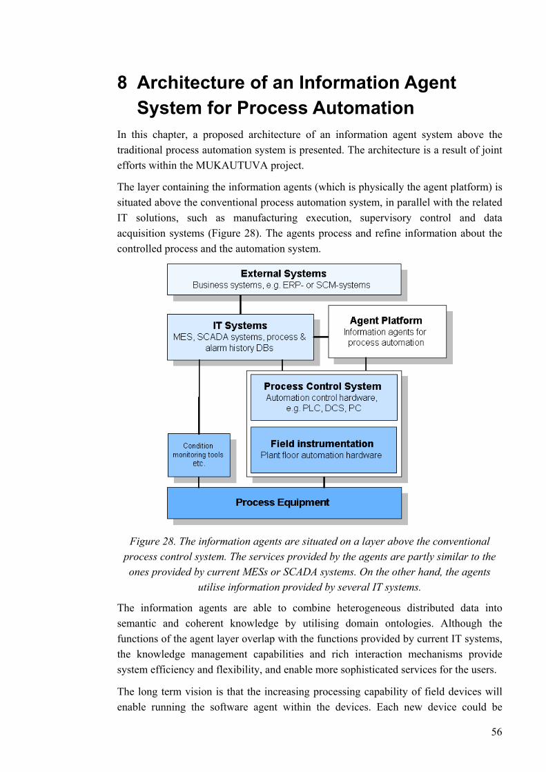
8 Architecture of an Information Agent System for Process Automation
In this chapter, a proposed architecture of an information agent system above the traditional process automation system is presented. The architecture is a result of joint efforts within the MUKAUTUVA project.
The layer containing the information agents (which is physically the agent platform) is situated above the conventional process automation system, in parallel with the related IT solutions, such as manufacturing execution, supervisory control and data acquisition systems (Figure 28). The agents process and refine information about the controlled process and the automation system.
Figure 28. The information agents are situated on a layer above the conventional process control system. The services provided by the agents are partly similar to the ones provided by current MESs or SCADA systems. On the other hand, the agents
utilise information provided by several IT systems.
The information agents are able to combine heterogeneous distributed data into semantic and coherent knowledge by utilising domain ontologies. Although the functions of the agent layer overlap with the functions provided by current IT systems, the knowledge management capabilities and rich interaction mechanisms provide system efficiency and flexibility, and enable more sophisticated services for the users.
The long term vision is that the increasing processing capability of field devices will enable running the software agent within the devices. Each new device could be
56

incorporated in the system automatically with the help of the software agent provided with the device. At present, however, the agents can at most be distributed to process control stations. Each device can be represented by a software agent, but physically the agents are situated in a separate platform above the instrumentation level.
8.1 Architecture of the agent society The composition of the agent society is based on a physical division of the controlled process (Figure 29 demonstrates an exemplar division for a fictitious process) and, on the other hand, on the functional division of agent tasks.
Figure 29. The composition of the agents is on one hand based on the physical division of the controlled process. This exemplar setup uses a fictitious process to illustrate the
hierarchical division.
The functional division of the agent population is based on the various functions provided by the agents:
• Diagnostics: A hierarchically constructed society of process system agents produces highly abstract knowledge about the state of the system, utilising diverse computational methods. The agents warn operators, when a fault situation is building up, or if the system is not operating optimally.
• Monitoring: The agents monitor devices and process variables, proactively utilising all methods attainable (the built-in monitoring applications in intelligent devices, process system dependencies on the basis of a model, sample quality measurements etc.) (For further discussion, see section 10.1)
• Alarm handling: The agents filter a flood of alarms, negotiating and using a model of the process system to find out the actual cause of the fault situation.
57
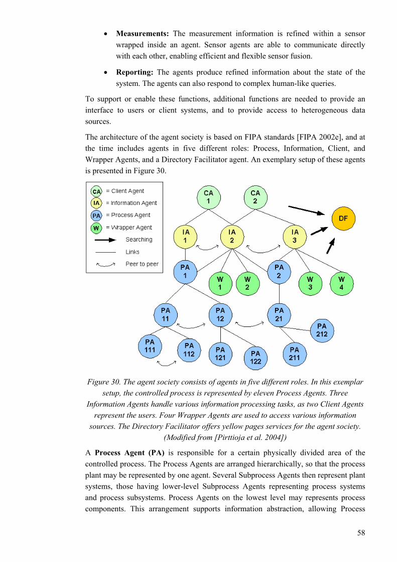
• Measurements: The measurement information is refined within a sensor wrapped inside an agent. Sensor agents are able to communicate directly
system. The agents can also respond to complex human-like queries.
The architecture of the agent society is based on FIPA standards [FIPA 2002e], and at the time includes agents in five different roles: Process, Information, Client, and Wrapper Agents, and a Directory Facilitator agent. An exemplary setup of these agents is presented in Figure 30.
with each other, enabling efficient and flexible sensor fusion.
• Reporting: The agents produce refined information about the state of the
To support or enable these functions, additional functions are needed to provide an interface to users or client systems, and to provide access to heterogeneous data sources.
Figure 30. The agent society consists of agents in five different roles. In this exemplar setup, the controlled process is represented by eleven Process Agents. Three
Information Agents handle various information processing tasks, as two Client Agents
g process systems and process subsystems. Process Agents on the lowest level may represents process components. This arrangement supports information abstraction, allowing Process
represent the users. Four Wrapper Agents are used to access various information sources. The Directory Facilitator offers yellow pages services for the agent society.
(Modified from [Pirttioja et al. 2004])
A Process Agent (PA) is responsible for a certain physically divided area of the controlled process. The Process Agents are arranged hierarchically, so that the process plant may be represented by one agent. Several Subprocess Agents then represent plant systems, those having lower-level Subprocess Agents representin
58
Agents on a higher level exchange refined knowledge of the process. (See Figure 29 for an example, on how the areas of responsibility can be divided.)
The function of the Process Agents is to maintain knowledge about the state of their
st an Information Agent to notify when a certain condition is fulfilled,
y a client, and translates client requests to ontology-based agent communication. There may be several different Client Agents providing custom
ation systems; databases, networks, or files. The agents extract the information, e.g. by using an OPC or an ODBC interface. The information, which
ical information about value trends, or asked to notify, if a certain value exceeds an alarm limit. Distributing simple
The Directory Facilitator (DF) is a yellow pages service provider defined by the
ation Agents are often intertwined. Also, the Wrapper Agents offer services similar to those of the Information Agents, the
o process systems (governed by PA1 and PA2), with several subprocesses and process components. The
area of responsibility. The agents produce a refined notion of the state, on the basis of e.g. the process value measurements of their domain.
The Information Agents (IA) respond to information queries and monitor changes within the system. They collect and distribute information produced by other agents, combining and refining it into knowledge on a higher level of abstraction. The user may requeleaving it up to the agent to reason which information is needed to conclude the response.
The population of the Information Agents is inherently dynamic, as new agents for new monitoring tasks can be invoked or discarded at runtime.
A Client Agent (CA) provides an interface for human users or external applications (for instance an ERP system). It presents information provided by the agents in a form understood b
interfaces for human users with different roles, such as operators, maintenance people, or managers.
The Wrapper Agents (W) are used to access heterogeneous information sources, typically legacy inform
may be in different syntaxes and at different levels of abstraction, is then mapped to the common ontology.
In addition to being able to translate information to a form understood by the agents, the Wrapper Agents also provide information processing and monitoring services. A Wrapper Agent may be requested for e.g. statist
processing tasks to the Wrappers makes it possible for the Process and Information Agents to process knowledge on a higher level.
FIPA Agent Management Specification [FIPA 2002a]. There may be several DFs in a single agent platform, and DFs may register with each other to form federations.
An individual agent may well operate concurrently in different roles. Especially the roles of the Process and the Inform
difference being the source of the information (external systems or other agents of the society) and the level of abstraction.
In Figure 30, the agents operate on a domain consisting of tw
59
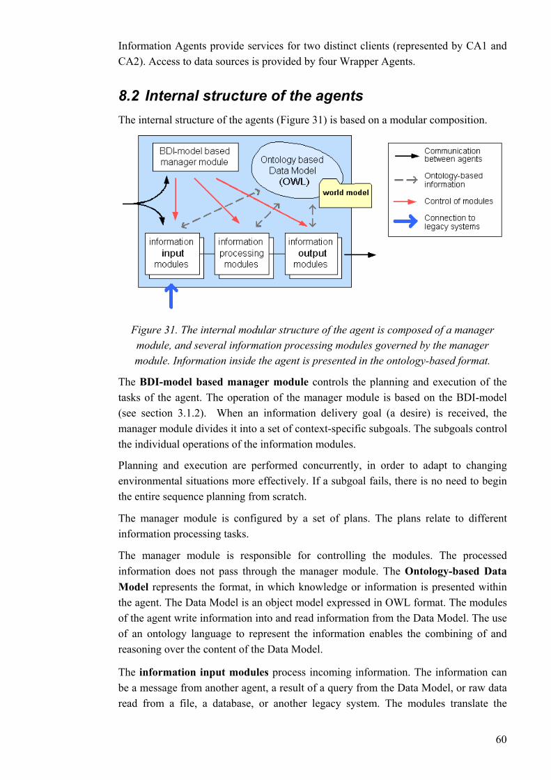
Information Agents provide services for two distinct clients (represented by CA1 and CA2). Access to data sources is provided by four Wrapper Agents.
8.2 Internal structure of the agents The internal structure of the agents (Figure 31) is based on a modular composition.
ule is based on the BDI-model
modules.
effectively. If a subgoal fails, there is no need to begin the entire sequence planning from scratch.
xpressed in OWL format. The modules
t of a query from the Data Model, or raw data read from a file, a database, or another legacy system. The modules translate the
Figure 31. The internal modular structure of the agent is composed of a manager module, and several information processing modules governed by the manager module. Information inside the agent is presented in the ontology-based format.
The BDI-model based manager module controls the planning and execution of the tasks of the agent. The operation of the manager mod(see section 3.1.2). When an information delivery goal (a desire) is received, the manager module divides it into a set of context-specific subgoals. The subgoals control the individual operations of the information
Planning and execution are performed concurrently, in order to adapt to changing environmental situations more
The manager module is configured by a set of plans. The plans relate to different information processing tasks.
The manager module is responsible for controlling the modules. The processed information does not pass through the manager module. The Ontology-based Data Model represents the format, in which knowledge or information is presented within the agent. The Data Model is an object model eof the agent write information into and read information from the Data Model. The use of an ontology language to represent the information enables the combining of and reasoning over the content of the Data Model.
The information input modules process incoming information. The information can be a message from another agent, a resul
60
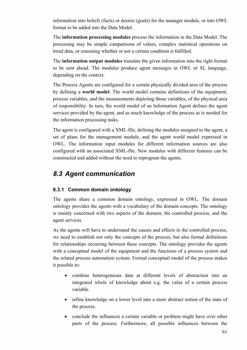
information into beliefs (facts) or desires (goals) for the manager module, or into OWL format to be added into the Data Model.
The information processing modules process the information in the Data Model. The
odules translate the given information into the right format
ld model of an Information Agent defines the agent
model expressed in OWL. The information input modules for different information sources are also configured with an associated XML-file. New modules with different features can be
reprogram the agents.
re a common domain ontology, expressed in OWL. The domain ontology provides the agents with a vocabulary of the domain concepts. The ontology
s occurring between these concepts. The ontology provides the agents with a conceptual model of the equipment and the functions of a process system and the re eit possibl
• combine heterogeneous data at different levels of abstraction into an
• re, all possible influences between the
processing may be simple comparisons of values, complex statistical operations on trend data, or reasoning whether or not a certain condition is fulfilled.
The information output mto be sent ahead. The modules produce agent messages in OWL or SL language, depending on the context.
The Process Agents are configured for a certain physically divided area of the process by defining a world model. The world model contains definitions of the equipment, process variables, and the measurements depicting those variables, of the physical area of responsibility. In turn, the worservices provided by the agent, and as much knowledge of the process as is needed for the information processing tasks.
The agent is configured with a XML-file, defining the modules assigned to the agent, a set of plans for the management module, and the agent world
constructed and added without the need to
8.3 Agent communication
8.3.1 Common domain ontology
The agents sha
is mainly concerned with two aspects of the domain; the controlled process, and the agent services.
As the agents will have to understand the causes and effects in the controlled process, we need to establish not only the concepts of the process, but also formal definitions for relationship
lat d process automation system. Formal conceptual model of the process makes e to:
integrated whole of knowledge about e.g. the value of a certain process variable.
• refine knowledge on a lower level into a more abstract notion of the state of the process.
conclude the influences a certain variable or problem might have over other parts of the process. Furthermo
61
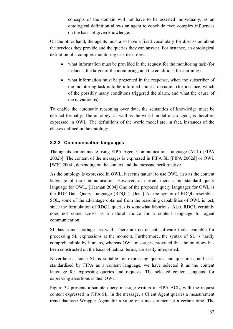
concepts of the domain will not have to be asserted individually, as an ontological definition allows an agent to conclude even complex influences on the basis of given knowledge.
On ththe services they provide and the queries they can answer. For instance, an ontological defini n
•
• must be presented in the response, when the subscriber of
ing over data, the semantics of knowledge must be defined formally. The ontology, as well as the world model of an agent, is therefore
e world model are, in fact, instances of the
uery Language (RDQL). [Jena] As the syntax of RDQL resembles SQL, some of the advantage obtained from the reasoning capabilities of OWL is lost,
SL has some shortages as well. There are no decent software tools available for
Nevertheless, since SL is suitable for expressing queries and questions, and it is
ample query message written in FIPA ACL, with the request content expressed in FIPA SL. In the message, a Client Agent queries a measurement trend database Wrapper Agent for a value of a measurement at a certain time. The
e other hand, the agents must also have a fixed vocabulary for discussion about
tio of a complex monitoring task describes:
what information must be provided in the request for the monitoring task (for instance, the target of the monitoring, and the conditions for alarming).
what information the monitoring task is to be informed about a deviation (for instance, which of the possibly many conditions triggered the alarm, and what the cause of the deviation is).
To enable the automatic reason
expressed in OWL. The definitions of thclasses defined in the ontology.
8.3.2 Communication languages
The agents communicate using FIPA Agent Communication Language (ACL) [FIPA 2002b]. The content of the messages is expressed in FIPA SL [FIPA 2002d] or OWL [W3C 2004], depending on the context and the message performative.
As the ontology is expressed in OWL, it seems natural to use OWL also as the content language of the communication. However, at current there is no standard query language for OWL. [Herman 2004] One of the proposed query languages for OWL is the RDF Data Q
since the formulation of RDQL queries is somewhat laborious. Also, RDQL certainly does not come across as a natural choice for a content language for agent communication.
processing SL expressions at the moment. Furthermore, the syntax of SL is hardly comprehendible by humans, whereas OWL messages, provided that the ontology has been constructed on the basis of natural terms, are easily interpreted.
standardised by FIPA as a content language, we have selected it as the content language for expressing queries and requests. The selected content language for expressing assertions is then OWL.
Figure 32 p sresents a
62
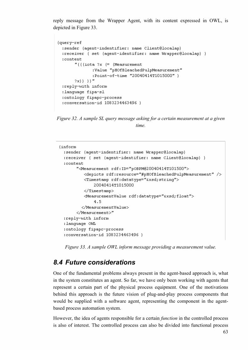
reply message from the Wrapper Agent, with its content expressed in OWL, is depicted in Figure 33.
Figure 32. A sample SL query message asking for a certain measurement at a given
time.
ssage providing a measurement value.
vision of plug-and-play process components that
in function in the controlled process be divided into functional process
Figure 33. A sample OWL inform me
8.4 Future considerations One of the fundamental problems always present in the agent-based approach is, what in the system constitutes an agent. So far, we have only been working with agents that represent a certain part of the physical process equipment. One of the motivations behind this approach is the futurewould be supplied with a software agent, representing the component in the agent-based process automation system.
However, the idea of agents responsible for a certais also of interest. The controlled process can also 63
phases. A certain physically divided area of the process may also execute a completely different function in different states of the system.
A simple and clear example of the functional approach is an agent monitoring a refined
architecture can be thought of
e field of discrete manufacturing automation and particularly in the HMS community (the PROSA architecture, see e.g. [Brennan & Norrie 2003] or [Mařík et al. 2002]).
tem
e Wrapper Agents, as well as the User Interface for the ented by the author. Other parts of the system were
In this chapter, we first list the software tools used in the implementation of the prototype system. The construction of the different modules and parts is then explained
FIPA-OS is a free, open-source agent platform. Released in 1999, it is also the first FIPA menvironm
• the logical components of the FIPA agent management reference model
process variable (e.g. consistency), which may be determined from many factors, and not directly linked to any physical piece of equipment.
It could also be argued that an Information Agent in our as an agent with responsibility for a functional area, as it is can be launched to monitor a certain process variable or a functional process phase.
Another interesting alternative to our composition is the concept of a product or a batch agent. The idea is that each manufactured product or processed batch would be represented by an agent that would e.g. maintain and exchange knowledge about the production state of the product or batch. The concept of a product agent has understandably gained attention in th
9 Implementation of the Agent SysThe prototype system was constructed by further developing the FIPA-PC system developed at Helsinki University of Technology ([Pirttioja 2002]).
The ontology, the data model (JENA) interfacing module, the plans and the database connection modules for thClient Agent were implemimplemented in collaboration with or single-handedly by Teppo Pirttioja of Helsinki University of Technology.
in respective sections.
9.1 Software tools
9.1.1 Introduction of the software tools used
-co pliant platform developed. FIPA-OS provides a Java-based runtime ent for the agents. It features:
[FIPA 2002a]; the Agent Management System, the Message Transport Service, and the Directory Facilitator.
64
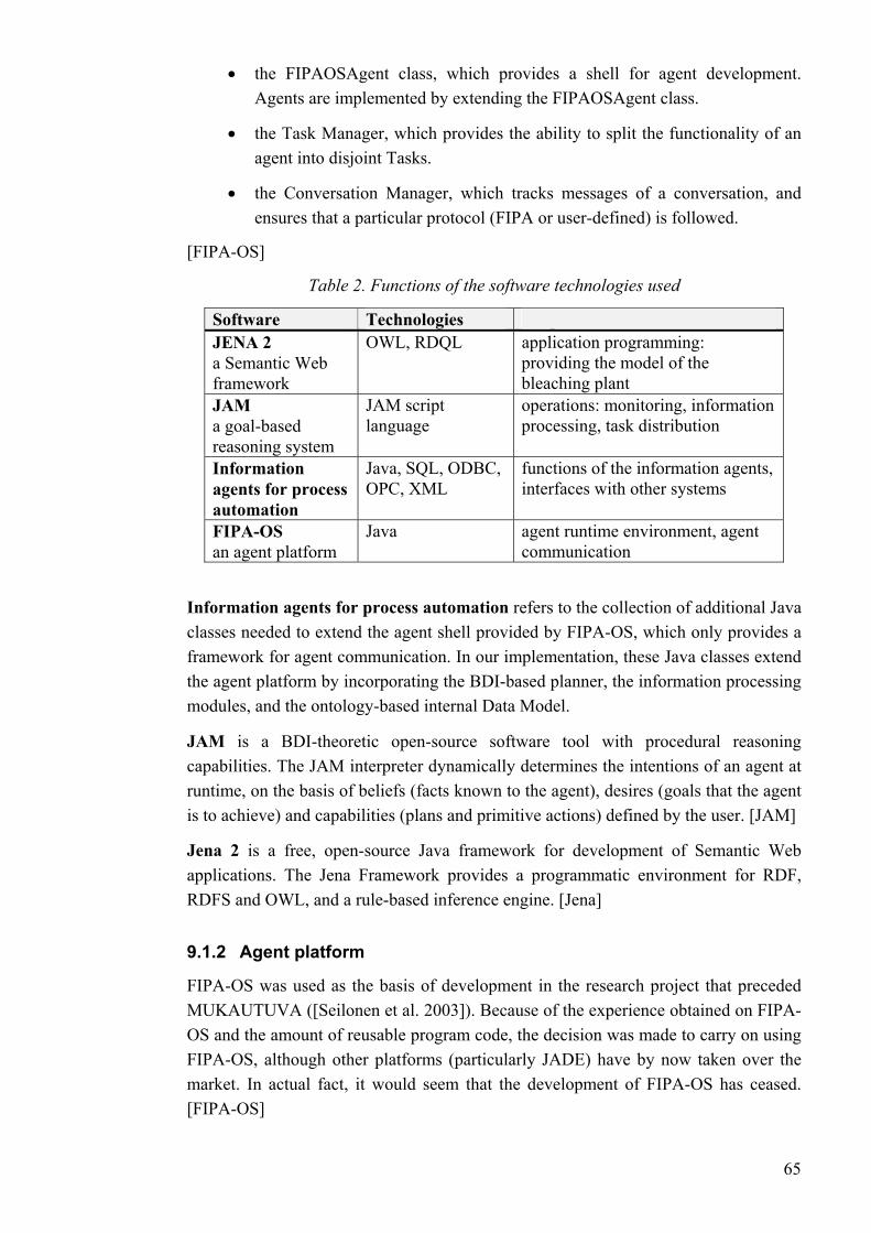
• the FIPAOSAgent class, which provides a shell for agent development. Agents are implemented by extending the FIPAOSAgent class.
Conversation Manager, which tracks messages of a conversation, and ensures that a particular protocol (FIPA or user-defined) is followed.
[FI
Table 2 e softw
• the Task Manager, which provides the ability to split the functionality of an agent into disjoint Tasks.
• the
PA-OS]
. Functions of th are technologies used
Software Purpose JENA 2
eb L
bleaching plant a Semantic Wframework
OWL, RDQ application programming: providing the model of the
JAM a goal-based reasoning system
JAM script language
operations: monitoring, information processing, task distribution
Information
automation
SQL, ODBC, OPC, XML
, ther systems agents for process
Java, functions of the information agentsinterfaces with o
Technologies
FIPA-OS an agent platform
Java agent runtime environment, agent communication
Information agents for process automation refers to the collection of additional Java classes needed to extend the agent shell provided by FIPA-OS, which only provides a framework for agent communication. In our implementation, these Java classes extend
capabilities. The JAM interpreter dynamically determines the intentions of an agent at
Jena 2 is a free, open-source Java framework for development of Semantic Web mework provides a programmatic environment for RDF,
RDFS and OWL, and a rule-based inference engine. [Jena]
mount of reusable program code, the decision was made to carry on using FIPA-OS, although other platforms (particularly JADE) have by now taken over the
the agent platform by incorporating the BDI-based planner, the information processing modules, and the ontology-based internal Data Model.
JAM is a BDI-theoretic open-source software tool with procedural reasoning
runtime, on the basis of beliefs (facts known to the agent), desires (goals that the agent is to achieve) and capabilities (plans and primitive actions) defined by the user. [JAM]
applications. The Jena Fra
9.1.2 Agent platform
FIPA-OS was used as the basis of development in the research project that preceded MUKAUTUVA ([Seilonen et al. 2003]). Because of the experience obtained on FIPA-OS and the a
market. In actual fact, it would seem that the development of FIPA-OS has ceased. [FIPA-OS]
65
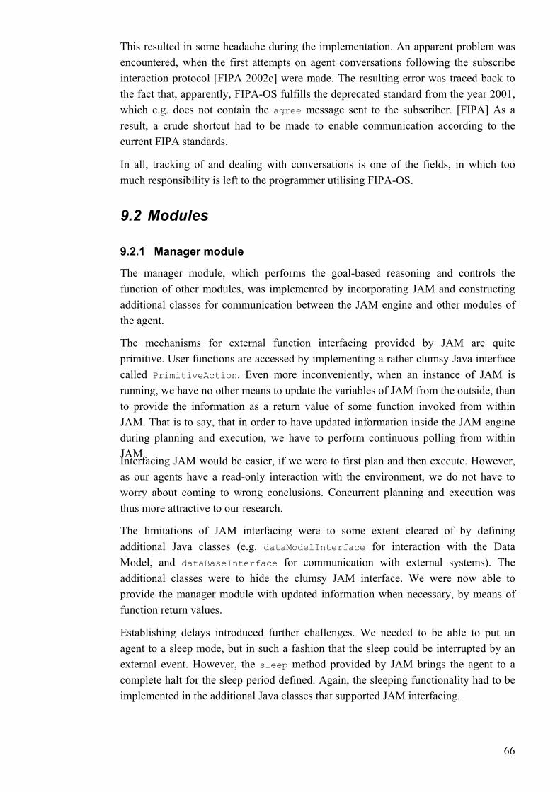
This resulted in some headache during the implementation. An apparent problem was encountered, when the first attempts on agent conversations following the subscribe interaction protocol [FIPA 2002c] were made. The resulting error was traced back to
scriber. [FIPA] As a result, a crude shortcut had to be made to enable communication according to the
s.
In all, tracking of and dealing with conversations is one of the fields, in which too he programmer utilising FIPA-OS.
nager module
g, we have no other means to update the variables of JAM from the outside, than
we were to first plan and then execute. However,
dataModelInterface
dataBaseInterface for communication with external systems). The
pted by an external event. However, the method provided by JAM brings the agent to a
unctionality had to be
the fact that, apparently, FIPA-OS fulfills the deprecated standard from the year 2001, which e.g. does not contain the agree message sent to the sub
current FIPA standard
much responsibility is left to t
9.2 Modules
9.2.1 Ma
The manager module, which performs the goal-based reasoning and controls the function of other modules, was implemented by incorporating JAM and constructing additional classes for communication between the JAM engine and other modules of the agent.
The mechanisms for external function interfacing provided by JAM are quite primitive. User functions are accessed by implementing a rather clumsy Java interface called PrimitiveAction. Even more inconveniently, when an instance of JAM is runninto provide the information as a return value of some function invoked from within JAM. That is to say, that in order to have updated information inside the JAM engine during planning and execution, we have to perform continuous polling from within JAM. Interfacing JAM would be easier, if as our agents have a read-only interaction with the environment, we do not have to worry about coming to wrong conclusions. Concurrent planning and execution was thus more attractive to our research.
The limitations of JAM interfacing were to some extent cleared of by defining additional Java classes (e.g. for interaction with the Data Model, and additional classes were to hide the clumsy JAM interface. We were now able to provide the manager module with updated information when necessary, by means of function return values.
Establishing delays introduced further challenges. We needed to be able to put an agent to a sleep mode, but in such a fashion that the sleep could be interru
sleep
complete halt for the sleep period defined. Again, the sleeping fimplemented in the additional Java classes that supported JAM interfacing.
66

9.2.2 Information input modules for database access
For our demonstration purposes, we needed two Wrapper Agents to access a
The interface to a database is provided by an implementation of an interface called DBAccess. An agent sets up a database connection by instantiating a class called
Factory, s th e database. e name is then abas ro p
ess interface is then loaded.
Table 3. The DBAccess interfac
measurement trend history database and a laboratory quality measurement database. For these agents, information input modules were needed that could be configured to access both the actual databases of the process automation system via ODBC, and text files containing fictitious test data.
To enable the use of multiple protocols for communication between the agents and legacy systems, the Factory Method design pattern was implemented. The Factory Method provides an interface for creating an object, but lets sub-classes decide which class to instantiate. [Gamma et al. 1994]
DBAccess pecifying e name of th The databasmatched to a dat e XML p file file name, and an a propriate implementation ofthe DBAcc
e
Method Returns Parametres Description setServerProfile boolean DBAccessProfile dbap le. Loads the database profi
Connects to theclose void - Closes the database
connection. executeOWLQy
uer String String query Executes a database query, providing the results in OWL format. Returns the latest value of
connect void - database.
getLatestOWL String String query the specified variable in OWL format.
executeQuery Vector String query Executes a database query, providing the results in a table (Vector of Vectors).
The query strings for the DBAccess classes (see Table 3) are expressed in format: keyword 'value'
For instance, a query for the values of a certain measurement after a certain time
nted in a
DummyDBAccessImpl artificial data.
would be written as follows:
Measurement 'pHOfPulpMeasurement' After '20040101T1600000'
The response may be serialised in OWL format, or the values can be presetable.
Two different implementations of the interface DBAccess were constructed; ODBCDBAccessImpl, which connects to a database using ODBC, and
, which connects to a text file containing
67

The implementations of DBAccess are configured with an XML profile file. The
d to be represented in the ontology language format. Therefore, the internal Data Model of the agent is an object model expressed in OWL.
To provide an object model with OWL API, and capable of automatic reasoning, Jena uced i n n 2 to
maintain its Data Model. This a 2 DataModel.
e te
profile file for ODBC access, for example, contains the name, description, and address of the database, the names of relevant fields and columns in the database, and additional information (e.g. the time representation format).
9.2.3 Data Model
To enable the ontology-based reasoning over data processed by the agent, data inside the agent ha
2 was introd nside the age t. Each agent runs a individual instance of Jenais accessed via a class called instance of Jen
Tabl 4. The DataModel in rface
Description dataModel odel
String dataURI hema) DataM String schemaURI Constructs a Data Model,
based on an ontology (scand a world model (data). Construcbased on an ontology (schema). Adds an class instance or severaexpressed in OWL, to the DModel. Resets the content of Model to its original state, removing all added indata. Executes an RDQL query, providin(Vector of Vectors). Returns the base ontology URfor this Data Model. Returns
Method Returns Parametres
dataModel DataModel String schemaURI ts a Data Model,
read void String OWLString l class instances,
ata
clear void - Data
stance
executeQuery Vector String queryString g the results in a table
getSchemaURI String - I
getFacts String String instance all the parametres of a class instance, in JAM Fact format.
getOWL String String rns a serialisation of the requested class instance, and all its parametres, in OWL
instance Retu
format.
The DataModel class is accompanied with a class called DataModelServices. The RDQL queries are formulated in the DataModelServices class, which contains an array of forms for different RDQL queries. These forms are then filled with keywords, depending on the query context.
68

Because Jena 2 is not able to provide query results in OWL format, but returns a Java ResultSet, we again have to construct the OWL response within the DataModelServices class, using predefined context-specific forms.
The payload on the system, caused by multiple agents, each running an individual 2, was roughly evaluated. Running many concurrent instances of Jena
ng task, the manager module divides it to a number of subtasks an associated to the task). These subtasks respond to atomic
The DataModel class automatically runs the inference engine of Jena 2 whenever necessary, e.g. when information is requested from the Data Model after its contents have been changed.
instance of Jena 2 proved to be an insignificant strain on the agent platform.
9.3 Plans The behaviour of an agent is defined in a set of plans. As an agent receives an information processi(specified in the ploperations that can be performed by the information processing modules. Planning and execution are performed simultaneously, enabling the agent to flexibly adapt to changing situations.
Figure 34. A greatly simplified excerpt of a fictitious JAM plan features a top-level goal and one of the subgoals needed to achieve the top-level goal.
To process the plans, the agents use a reasoning software called JAM. The plans are written in specific JAM script syntax (Figure 34). Goals and subgoals represent tasks
o the beliefs in BDI).
allocated to the agent (equivalent to the desires of the BDI-model). The plans also contain primitive actions, such as remote function calls. Information is presented as facts (equivalent t
69

The JAM engine is capable of dynamically combining the context-specific subgoals at runtime to achieve a given top-level goal. If a certain goal fails, the engine can attempt
9.4 Domain ontology As constructing a universally applicable domain ontology for process control is an immeontology representation and ontology-based information processing.
The im
• definitions of process equipment, variables and measurements relevant to the
the class definitions for the domain ontology, as well as some basis for the
ocessComponent
ides
t value. This example may seem trivial, but inverseOf and subPropertyOf are only two of the numerous fixed definitions that provide OWL with power of expression (see section 4.2.4). Thus the system is able to e.g. conclude all possible relationships between the objects, even though only a few of them are presented in the initial data.
another solution.
nse task, we focused more on experimenting with possible mechanisms for
plemented domain ontology consists of
test scenario,
• definitions of services provided by an agent, mainly for the purposes of the test scenario.
The process and process control aspects of the domain ontology were based on a conceptual model for process automation domain [MUKAUTUVA 2004] and a model of the application plant [MUKAUTUVA 2003] developed in the MUKAUTUVA research project. Based on the industrial standards of the field, the conceptual model providedrelationships between classes. The plant model then provided insight into the definitions of class relationships, and was also the basis for the ontology class instances for this particular application (that is to say, the agent world model, see below).
Figure 35 presents a simplified excerpt from the OWL domain ontology for demonstration purposes. The code defines a Sensor, being a subclass of a ProcessComponent. A Pr may provide a Value (depicting some process variable). The relationship prov is the inverse relationship of IsProvidedBy. Given these definitions, if we now specify a pH measurement value that isProvidedBy a pH sensor, the system is able to conclude that the relationship isRelatedToFunctional (which is the parent property of provides, which is the inverse property of isProvidedBy) exists between the sensor and the measuremen
70
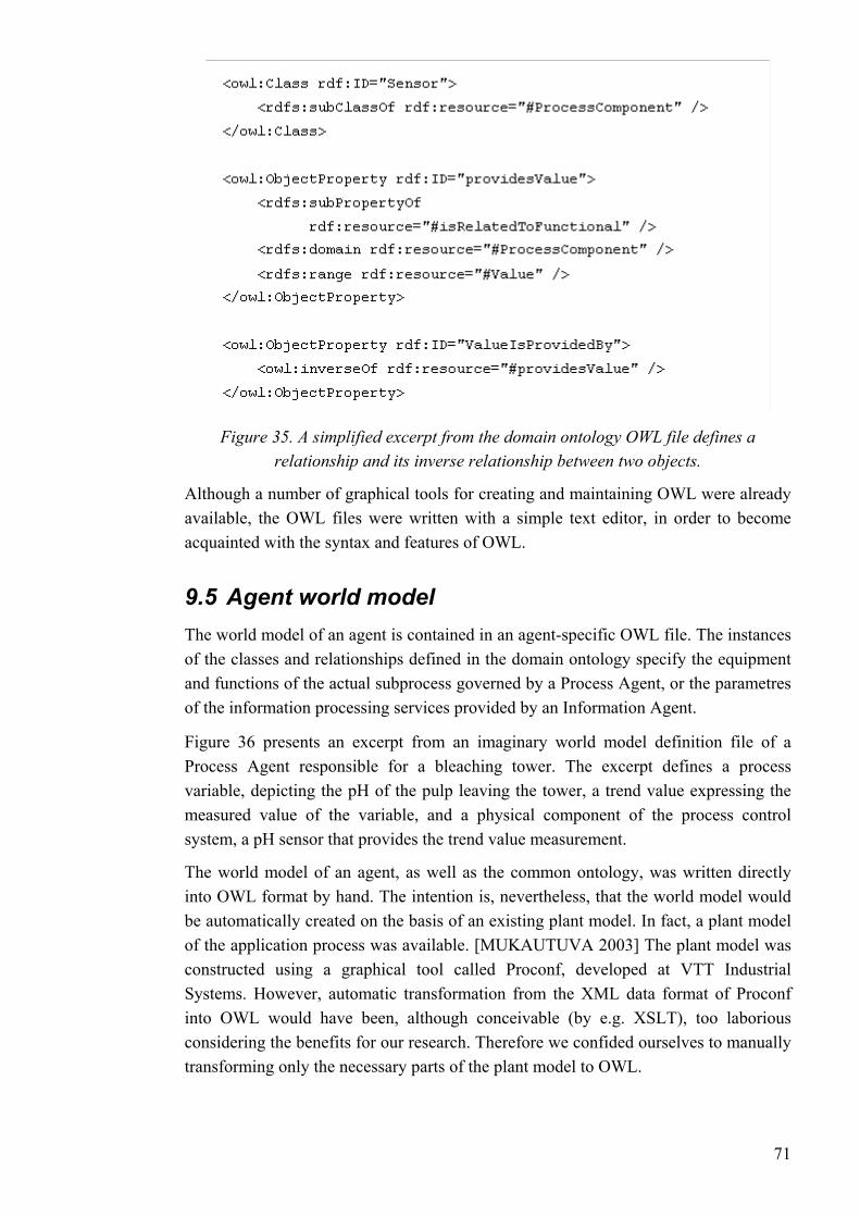
Figure 35. A simplified excerpt from the domain ontology OWL file defines a relationship and its inverse relationship between two objects.
Although a number of graphical tools for creating and maintaining OWL were already available, the OWL files were written with a simple text editor, in order to become acquainted with the syntax and features of OWL.
9.5 Agent world model The world model of an agent is contained in an agent-specific OWL file. The instances of the classes and relationships defined in the domain ontology specify the equipment and functions of the actual subprocess governed by a Process Agent, or the parametres of the information processing services provided by an Information Agent.
Figure 36 presents an excerpt from an imaginary world model definition file of a Process Agent responsible for a bleaching tower. The excerpt defines a process variable, depicting the pH of the pulp leaving the tower, a trend value expressing the measured value of the variable, and a physical component of the process control system, a pH sensor that provides the trend value measurement.
The world model of an agent, as well as the common ontology, was written directly into OWL format by hand. The intention is, nevertheless, that the world model would be automatically created on the basis of an existing plant model. In fact, a plant model of the application process was available. [MUKAUTUVA 2003] The plant model was constructed using a graphical tool called Proconf, developed at VTT Industrial Systems. However, automatic transformation from the XML data format of Proconf into OWL would have been, although conceivable (by e.g. XSLT), too laborious considering the benefits for our research. Therefore we confided ourselves to manually transforming only the necessary parts of the plant model to OWL.
71
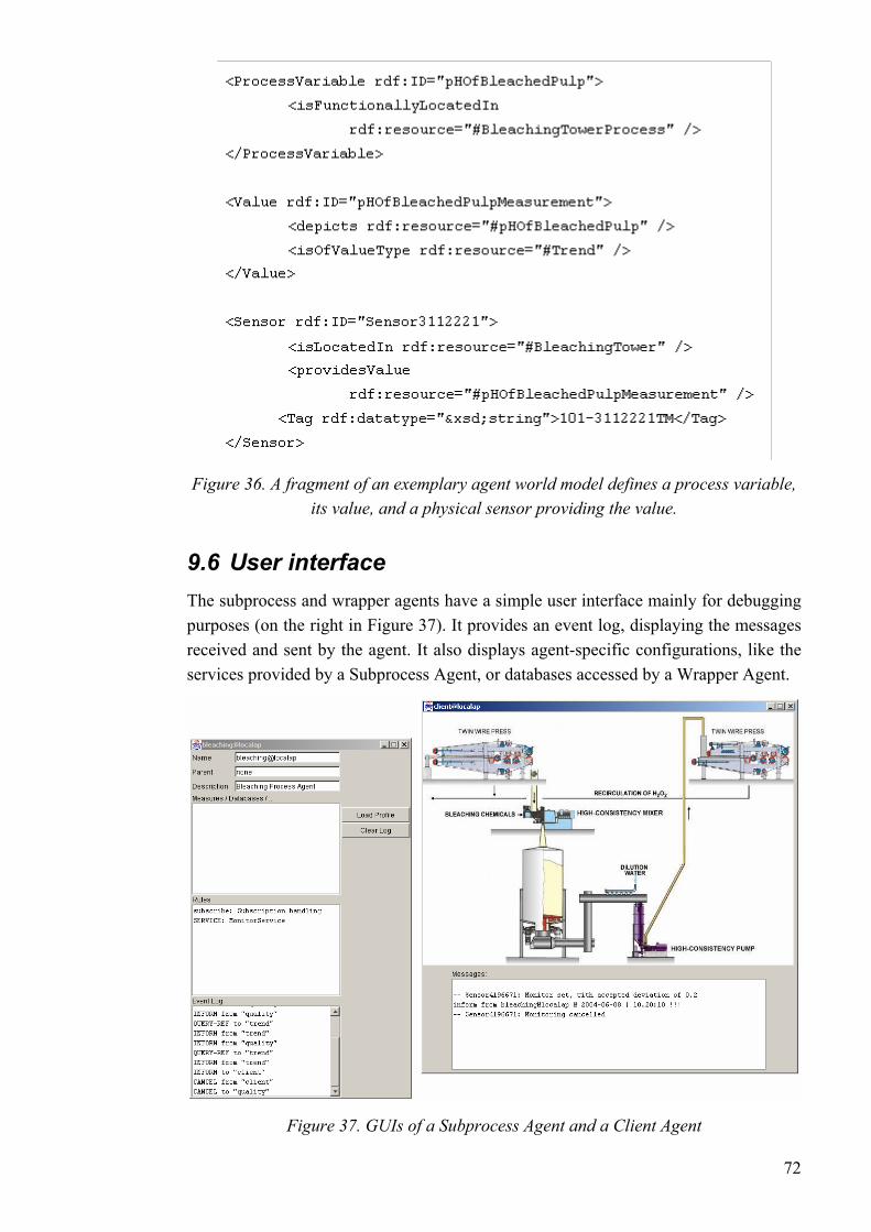
Figure 36. A fragment of an exemplary agent world model defines a process variable, its value, and a physical sensor providing the value.
9.6 User interface The subprocess and wrapper agents have a simple user interface mainly for debugging purposes (on the right in ). It provides an event log, displaying the messages received and sent by the agent. It also displays agent-specific configurations, like the services provided by a Subprocess Agent, or databases accessed by a Wrapper Agent.
Figure 37
Figure 37. GUIs of a Subprocess Agent and a Client Agent
72

The actual user interfacing is done via a user-specific Client Agent. The Client Agent UI (on the right in Figure 37) has a graphical view of the application process, and a text box displaying events related to the Client Agent. Incoming inform-messages from other agents are also displayed in a separate popup window.
The process view consists of active elements, which represent process components. A mouse click on an active element opens up a popup menu that shows the services provided for the element.
The coordinates of the active elements, as well as the process equipment they represent, are defined in the XML configuration file of the Client Agent.
10 Tests In this chapter, a test for our implementation of the proposed agent architecture is demonstrated. This fairly simple test scenario is the first experiment with our implementation, and being successful, it is to be followed by more complicated scenarios in the future. The demonstrated scenario, however, corresponds to a relevant problem identified in the application process. Production quality laboratory measurements could be utilised in condition monitoring of vulnerable sensor devices, but current systems do not enable this in a feasible manner.
First, the test scenario with its motivation is presented. Then we look at the configuration of the implemented agent system for this setting. The behaviour expressed by the agents during the test run is then presented. Finally, conclusions of the test are made.
10.1 Test scenario: sensor monitoring Among other instruments in a bleaching process plant, pH sensors are vulnerable to defects. To automatically monitor the performance of sensor, the plant may e.g. be equipped with duplicated measurements (increased redundancy). However, condition monitoring of a sensor could also be based on functional knowledge of the process (concluding the actual value of the pH on the basis of its known influence on other variables of the process, in a way of sensor fusion) or other kind of knowledge we can obtain, related to the pH value. In our test scenario, we experimented with the utilisation of a laboratory quality measurement in condition monitoring of a pH sensor.
As other crucial production variables, the pH value of the pulp after the actual bleaching process (after the bleaching tower) is observed by means of a laboratory quality measurement. Few times a day, a factory operator collects a sample of the pulp, and the pH is measured in laboratory circumstances.
73
The laboratory measurement is principally used for production quality monitoring, but the information would also be useful in monitoring the operation of the pH sensor. Once in a while, an operator may manually compare the laboratory results with the
measurement. It only has a few discrete values
ent value could be obtained from esystem. T
•
ory measurement database). The system should be able to
• olled
appear.)
iptions, reducing the amount of simple polling. Distributed
provided us with a reasonably illustrative test scenario for our agent architecture.
trend measurement history. However, there is always a considerable delay, before a defect is noticed in this manner.
The comparison between the laboratory measurement and the value provided by the sensor cannot be performed automatically. The laboratory measurement is fed into a different database in a different computer system. The nature of the laboratory measurement is also fundamentally different; it is a somewhat certain "truth", as opposed to the always uncertain sensor several hours apart, as opposed to the measurement of the sensor, the value of which can be read as frequently as necessary.
Using state-of-the-art technology, the laboratory measurema r mote database, and an alarm limit could be set into the process automation
he drawbacks of current solutions, however, are:
If information must be imported from another system, the operator needs to be able to identify the corresponding value tag in the remote system (in this case, the laboratautomatically identify all the pieces of information that could be utilised in the monitoring.
Current solutions (e.g. OPC alarm limits) rely on continuous data polling. To reduce and rationalise the necessary communication, data should be ponly at the lowest level, and only when necessary. (In this case, we should be able to subscribe to the new laboratory measurements, as they
• Utilisation of more sophisticated methods for identifying a fault (e.g. statistical methods instead of simple comparison) is limited.
A population of information processing agents could provide a solution to the aforementioned limitations. Ontological representation of the process data could enable the identification and integration of all the pieces of information related to the problem. Autonomous process agents would even actively come up with new ways to solve the problem if, for example, a new sensor device is introduced into the system. Speech act performatives already describe established methods for handling of requests and subscrprocessing of the information enables easy incorporation of different information processing methods. The condition monitoring of a pH sensor by comparing it with a laboratory measurement
74

10.2 Test configuration
10.2.1 The agent population
For the test scenario, four agents were constructed (Figure 38). Because the task is focused on individual process components, only one Process Agent was needed; the Bleaching Process Agent. The agent has the roles of both a Process Agent and an Information Agent in this scenario.
To provide a user interface for an operator, a Client Agent was added. Two Wrapper Agents provide access to laboratory measurement (Quality Wrapper Agent) and trend history (Trend Wrapper Agent) databases. The fifth agent of the population is the Directory Facilitator provided by the FIPA-OS agent platform.
Figure 38. The agent population of the test scenario consists of five agents.
For the Bleaching Process Agent and the Wrapper Agents, an information input/output module for FIPA-based agent communication called "Conversation" was developed. To provide access to the off-line measurement data file, another input/output module called "Database" was added. To perform the simple mathematics of the measurement value comparison, a light information processing module, "Reasoner", was implemented.
The Database module was also configured to access the trend history and laboratory measurement databases used in the actual bleaching plant. The module connected to the databases using ODBC. This was demonstrated in another, earlier scenario.
10.2.2 The configuration of the agent population
Since both the Bleaching Process Agent and the Quality Wrapper Agent primarily respond to subscriptions, a common upper level plan for subscription management was
75
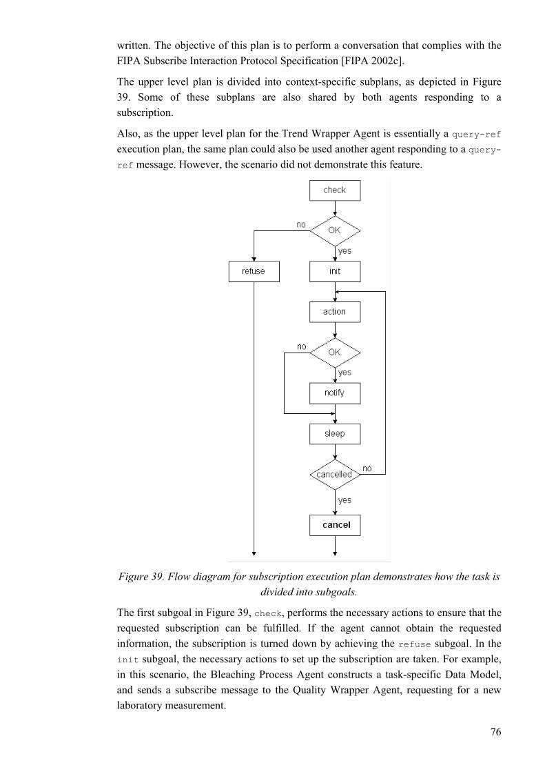
written. The objective of this plan is to perform a conversation that complies with the FIPA Subscribe Interaction Protocol Specification [FIPA 2002c].
The upper level plan is divided into context-specific subplans, as depicted in . Some of these subplans are also shared by both agents responding to a
subscription.
Figure 39
Figure 39. Flow diagram for subscription execution plan demonstrates how the task is divided into subgoals.
Also, as the upper level plan for the Trend Wrapper Agent is essentially a query-ref execution plan, the same plan could also be used another agent responding to a query-ref message. However, the scenario did not demonstrate this feature.
The first subgoal in Figure 39, check, performs the necessary actions to ensure that the requested subscription can be fulfilled. If the agent cannot obtain the requested information, the subscription is turned down by achieving the refuse subgoal. In the init subgoal, the necessary actions to set up the subscription are taken. For example, in this scenario, the Bleaching Process Agent constructs a task-specific Data Model, and sends a subscribe message to the Quality Wrapper Agent, requesting for a new laboratory measurement.
76

The action subgoal defines the repeated functionality that was the object of the subscription. In this case, the function is to compare the laboratory measurement with the trend value. The operations of the action subgoal are presented in detail in section 10.3.2. If, after the requested task has been performed, there is a need to inform the Client Agent of a result, it is done within the notify subgoal.
Finally, the agent runs a sleep subgoal, with its length depending on the context, concurrently waiting for the subscription to be cancelled. The cancel subgoal consists of necessary actions in canceling the subscription, including canceling the subscriptions or other commitments made further.
Due to the nature of the task, a complex model of the process was not needed. Therefore, the agents shared a common world model, i.e. a common OWL configuration file.
10.3 Test run The demonstration was conducted off-line using fictitious data. Instead of connecting to an actual database, the Wrapper Agents were reading a text file. In the actual process, laboratory measurements are taken every eight hour, and an actual failure of a sensor would have been difficult to simulate.
Nevertheless, to experiment with the stability of the agent platform, additional tests were also conducted, in which the agents were left monitoring the process for tens of hours, until a simulated defect was introduced.
10.3.1 Interactions of the agents
The interactions occurring between the agents during the monitoring task are presented in Figure 40. The conversation complies with the FIPA Subscribe Interaction Protocol Specification [FIPA 2002c].
The monitoring task is initiated by the Client Agent. The user clicks the pH sensor in the process view, and selects the option "Monitor -> Compare to quality
measurement" from the appearing popup menu. The user is then prompted for an accepted deviation of the measurement from the corresponding laboratory quality measurement, the default value being 0,2. The Client Agent then sends a subscribe message to the Bleaching Process Agent, containing the name of the requested service, the name of the sensor to be monitored, and the accepted deviation.
First, the Bleaching Process Agent searches the Directory Facilitator for Wrapper Agents capable of providing the measurement values for the given sensor. If the measurements can be found, the Process Agent sends an agree message to the Client Agent, signifying that the subscription was understood and accepted.
77
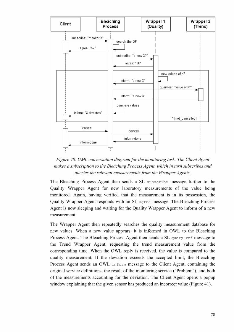
Figure 40. UML conversation diagram for the monitoring task. The Client Agent makes a subscription to the Bleaching Process Agent, which in turn subscribes and
queries the relevant measurements from the Wrapper Agents.
The Bleaching Process Agent then sends a SL subscribe message further to the Quality Wrapper Agent for new laboratory measurements of the value being monitored. Again, having verified that the measurement is in its possession, the Quality Wrapper Agent responds with an SL agree message. The Bleaching Process Agent is now sleeping and waiting for the Quality Wrapper Agent to inform of a new measurement.
The Wrapper Agent then repeatedly searches the quality measurement database for new values. When a new value appears, it is informed in OWL to the Bleaching Process Agent. The Bleaching Process Agent then sends a SL query-ref message to the Trend Wrapper Agent, requesting the trend measurement value from the corresponding time. When the OWL reply is received, the value is compared to the quality measurement. If the deviation exceeds the accepted limit, the Bleaching Process Agent sends an OWL inform message to the Client Agent, containing the original service definitions, the result of the monitoring service ("Problem"), and both of the measurements accounting for the deviation. The Client Agent opens a popup window explaining that the given sensor has produced an incorrect value (Figure 41).
78
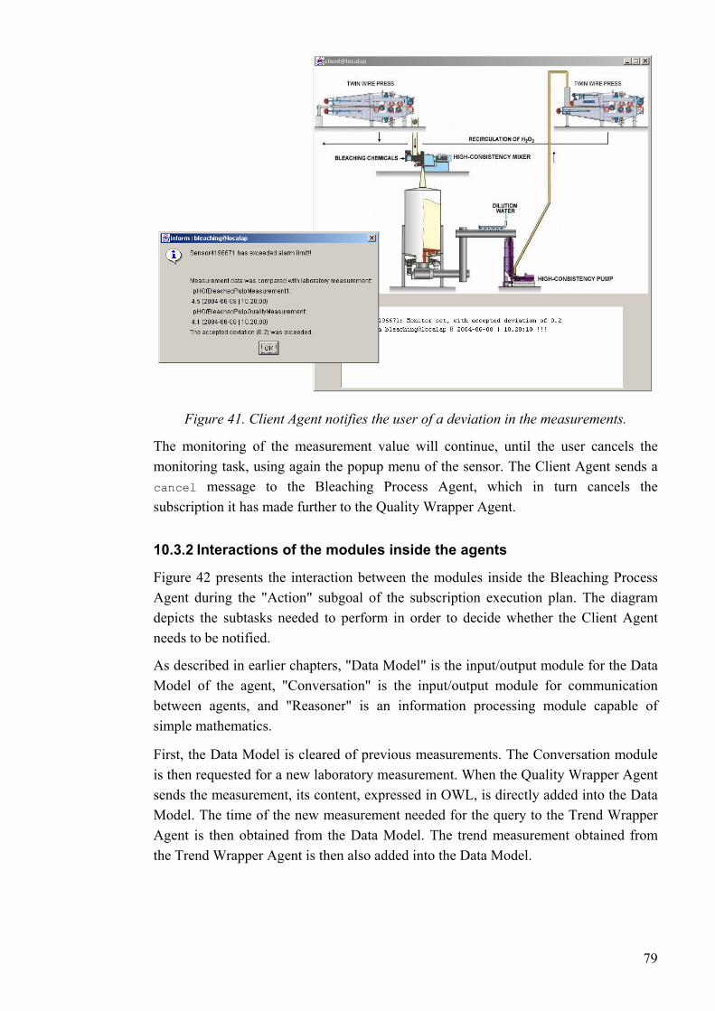
Figure 41. Client Agent notifies the user of a deviation in the measurements.
The monitoring of the measurement value will continue, until the user cancels the monitoring task, using again the popup menu of the sensor. The Client Agent sends a cancel message to the Bleaching Process Agent, which in turn cancels the subscription it has made further to the Quality Wrapper Agent.
10.3.2 Interactions of the modules inside the agents
Figure 42 presents the interaction between the modules inside the Bleaching Process Agent during the "Action" subgoal of the subscription execution plan. The diagram depicts the subtasks needed to perform in order to decide whether the Client Agent needs to be notified.
As described in earlier chapters, "Data Model" is the input/output module for the Data Model of the agent, "Conversation" is the input/output module for communication between agents, and "Reasoner" is an information processing module capable of simple mathematics.
First, the Data Model is cleared of previous measurements. The Conversation module is then requested for a new laboratory measurement. When the Quality Wrapper Agent sends the measurement, its content, expressed in OWL, is directly added into the Data Model. The time of the new measurement needed for the query to the Trend Wrapper Agent is then obtained from the Data Model. The trend measurement obtained from the Trend Wrapper Agent is then also added into the Data Model.
79

Figure 42. UML conversation diagram for the action subgoal. The Manager module controls the information processing modules.
The Reasoner is now assigned to conclude, whether the deviation of the values exceeds the accepted limit. The Reasoner queries the Data Model for the necessary information, and calculates the division. The conclusion is then returned to the manager module.
10.4 Test conclusions
pt to new devices and measurements was also demonstrated. An
the monitoring task could be subscribed for the brightness sensor.
When run, the system demonstrated the behaviour described in the conversation diagrams above. The interactions presented were not a result of pre-defined directions, but of runtime goal-orientated planning and dynamic agent co-operation. Lower-level tasks (desires) were combined in order to achieve a higher-level goal (intention). Thus, in our demonstration setting, agent-based and ontology-driven task decomposition held up to its promise.
The ability to adaadditional measurement, depicting the brightness of the bleached pulp, was introduced. The sensor, the measurement, and the corresponding laboratory measurement, were added into the world model of the agents, and to the configuration file of the database connection module (and measurement data was inserted to the fictitious off-line history database). The new information was immediately adopted by the agents, and
80
11 Conclusions
11.1 Summary and conclusions ultiagent systems were examined. The iques in information processing and in the
domain of process automation were studied, and some applications were presented. An cess automation systems was
ed. Secondly, there is an evident need for methods and
ntcities network. On the other hand, FIPA has
investigation into the possibilities of the multiagent approach, but our
monitoring task would
sed to be able to
In this thesis the basic concepts of mapplicability and possibilities of agent techn
agent architecture for information processing of prointroduced. An agent system implementing the architecture was devised and tested in a condition monitoring scenario.
A number of questions about adapting the agent-based approach in general - let alone in the domain of process automation - still remain unanswered. Firstly, it is unclear what part of a system constitutes an agent, or how the organisational relationships between agents should be definsoftware tools that are more reliable, detailed and domain-specific than the options currently available, particularly in the domain of process automation. Nonetheless, agent-based software engineering does not rule out taking advantage of general software engineering principles and products, as far as they are suited or can be easily tailored to the agent-based orientation.
Nevertheless, the field of agent-based computing has benefited enormously from the standardisation efforts of FIPA: there is not much confusion about the basic terminology, and the communication standards have even spawned global collaboration projects, such as the Ageconsciously left many issues unsettled not to restrict the research activities and innovations.
Our test scenario was unfortunately not the best one for demonstrating the advantages of multiagent systems in process automation. We were, however, able to experiment with the mechanisms of agent-based computing. There is a growing need for deterministic research has provided us with valuable hands-on experience with the mechanisms involved, giving insight into the potential of the technologies.
However, the test scenario demonstrates quite clearly, how an agent-based approach can even in simple tasks rationalise the behaviour of the system, facilitate the user interfacing, increase the flexibility, and enable easy incorporation of new features. The utilisation of a more sophisticated method for the conditionhave been a fairly trivial task, thanks to the modularity of the design.
Evidently, there is no reason to expect that an agent-based approach would yield an optimal system. There is even doubt about the overall reliability of many agent interaction mechanisms. One should remember that the objective of the agent-based approach is not to produce an optimal solution; instead, it is suppo
81
handle a massive, complex and dynamic system. It is very difficult cope with such circumstances using centralised solutions.
Even if the agent-based approach is not be adopted as such, it is, nonetheless, very likely that some of the many sophisticated characteristics of agent-based systems will be seen in future information systems.
11.2 Evaluation of the techniques and tools used Despite its standard status, the FIPA Semantic Language (SL) proved impractical in our research. Although SL strives to be very expressive in general, it is not always the optimal solution for a specific application. There is also an apparent lack of suitable
ditions. There have been suggestions for a query language -
receding research, and the amount of reusable program code. However, as
applications.
The lack of proper software tools for multiagent system development is the natural
tools for processing SL.
OWL, by contrast, is an expressive language for conceptual modelling. The three different sublanguages of OWL ease its implementation in different applications. However, the use of OWL in agent communication is complicated by the difficulty in expressing queries or conbased on the syntax of SQL or OWL itself - but none of these have been endorsed by W3C so far.
Most of the software tools utilised in our project have proven to be at least somewhat adequate for the task they were intended. Most problems were caused by the use of an outdated agent platform, FIPA-OS. FIPA-OS was selected because of the experience obtained in pthe development of FIPA-OS has ceased, while the FIPA standards have continued to evolve, the platform complies with the standards no longer. This resulted in e.g. incapability of our agents to carry out conversations according to FIPA conversation protocols.
The free JADE platform has gained superior popularity. The commercial JACK platform is also attractive since it incorporates the belief-desire-intention -architecture. The integration of BDI to the FIPA-OS platform was one of our most significant problems.
The tool used for planning and thus incorporating the BDI model was JAM. JAM is quite suitable for procedural goal-based planning, to which task it is intended. However, the poor communication capabilities of JAM make it quite unsuitable for multiagent
Jena 2, the software toolkit for ontology processing, has proven reliable and efficient. The poor query features of Jena 2 are not a fault of the software itself, since a proper query language for OWL has not been standardised yet.
consequence of the lack of established methods in the field of agent-orientated software development.
82

11.3 Future challenges The use of agents in process automation remains a scientifically fascinating subject. The industry, however, has traditionally been slow in adapting novel technologies. The study of agents that participate in process control activities is not yet a fully feasible research subject as the reliability of agent-orientated techniques has not been put under thorough deterministic investigation yet. As information agents have a "read-only" relationship with the environment, reliability is not so critical an issue.
The information agent architecture presented in the thesis is still under development; the roles of agents and the structure of the agent society require further clarification. One interesting subject is the concept of a product or batch agent. The interaction mechanisms should also be tested in more complex test scenarios. The future test scenario of the MUKAUTUVA project will feature several process agents working proactively to classify the state of the bleaching process. On the other hand, a thorough investigation into the agent services in the process automation domain is also necessary.
Formally specified domain ontologies are necessary to enable automatic reasoning and information refinement. However, the construction of process automation ontologies is an immense task, requiring know-how on both the process automation systems and conceptual modelling. The need for formal representation of ontologies produces even further challenges.
Fortunately, the research in the Semantic Web community promotes the development of methods for formal ontological definitions. W3C specifications have paved the way for numerous software tools for ontology development and maintenance. It is evident that the current standard (Ontology Web Language, OWL) is not the final solution. But since new W3C languages have so far been fully compatible with the previous ones, work done on OWL is not likely to turn out wasted in the near future.
The availability of ontology languages and software tools for ontology development does not solve all the problems. An essential question is how the reasoning process is supposed to work in practice. One of our major challenges has been to decide how responsibility should be dealt out between the plans and the ontology. So far, universally applicable theories have not been presented. We have been more interested in the coordination of an agent population than the intelligence of an individual agent.
As can be concluded from the above, our process automation domain ontology is quite simple. The emphasis has been on experimenting with the mechanisms for ontology-based information processing, instead of creating a competent, general domain ontology. Constructing a qualified process automation domain ontology would require the participation of several key companies of the field and plenty of time.
RDF Schema is currently on the way to becoming state-of-the-art in conceptual modelling activities of the process automation industry. Althouglanguage, RDF Schema is still semantically poor compared to OWL.
h it is a formal
83

12 References [Agentcities 2003] Technical Input and Feedback to FIPA from Agentcities.RTD and
the Agentcities Initiative, Agentcities Technical Note 2003.
[AgentLink] European Network of Excellence for Agent-Based Computing, http://www.agentlink.org/ (5.4.2004)
[Anthanasiadis & Mitkas 2004] Anthanasias I. N., Mitkas P. A.: An agent-based intelligent environmental monitoring system. Management of Environmental Quality, An International Journal, 2004, Vol. 15, no. 3, pp. 238-249.
[Brennan & Norrie 2003] Brennan R.W., Harrie D. H.: From FMS to HMS. Published in: Deen S. M. (editors): Agent-Based Manufacturing - Advances in the Holonic Approach, pp. 31-49, Springer Verlag Berlin Heidelberg 2003.
[Bunch & al. 2004] Bunch L., Breedy M., Bradshaw J. M., Carvalho M., Suri N., Uszok A., Hansen J., Pechoucek M., Marik, V.: Software Agents for Process Monitoring and Notification, 2004 ACM Symposium on Applied Computing, pp. 94-99, ACM 2004.
[Chiu et al. 2003] Chiu S., Chen Y-L, Provan G., Maturana F., Staron R., Hall K.: Distributed Diagnostics & Reconfiguration for Shipboard Chilled Water System, 13th International Ship Control Systems Symposium (SCSS), Orlando, FL, April 2003.
[CORBA] The Object Management Groups's (OMG) CORBA Website, http://www.corba.org/ (8.10.2004)
[Corera et al. 1996] Corera J., Laresgoiti I., Jennings N.R.: Using Archon, Part 2: Electricity Transportation Management, IEEE Expert, 1996, Vol. 11, no. 6, pp. 71-79.
[Davies et al. 2003] Davies J., Fensel D., Van Harmelen F. (editors): Towards The Semantic Web - Ontology-Driven Knowledge Management, John Wiley & Sons Ltd, England 2003.
[Deen 2003] Deen S. M. (editor): Agent-Based Manufacturing - Advances in the Holonic Approach, Springer-Verlag Berlin Heidelberg 2003.
[Fensel 2001] Fensel D.: Ontologies - A Silver Bullet for Knowledge Management and Electronic Commerce, Springer Verlag 2001.
[Fensel et al. 2003] Fensel D., van Harmelen F., Horrocks I.: OIL and DAML+OIL: Ontology Languages for the Semantic Web. Published in: Davies J., Fensel D., Van Harmelen F. (editors): Towards The Semantic Web - Ontology-Driven Knowledge Management, John Wiley & Sons Ltd, England 2003.
[Ferber 1999] Ferber J.: Multi-Agent Systems: An Introduction to Distributed Artificial Intelligence. Addison-Wesley 1999.
84
[FIPA] The Foundation for Intelligent Physical Agents, http://www.fipa.org/ (1.4.2004) [FIPA 2001a] FIPA Ontology Service Specification, Experimental, FIPA 2001.
01.
2002.
[FIPA-OS] FIPA-OS Agent Platform, http://www.emorphia.com/research/about.htm
[Gibbins et al. 2004] Gibbins N., Harris S., Shadbolt N.; rvices and Agents on the World Wide Web
[Gruber 1993] Gruber T.: A Translation Approach to Portable Ontology
[Gruv acFarlane
ustrial Applications of Holonic and Multi-Agent Systems, HoloMAS 2003,
[Ham Virta 2003] Hammarström L., Virta K.: Teollisuusprosessien vaatimukset automaatiolle toteuttajan kannalta. Automaatioväylä, Vol. 6, 2003,
[Hem ntegration, VTT research notes 2149, VTT 2002. Available at:
[Herm rman I.: Towards the Semantic Web, Web Intelligence Symposium, STeP 2004, available at: http://www.w3.org/2004/Talks/0209-Helsinki-IH/
[HOLOBLOC] Holobloc - Function Block-Based, Holonic Systems Technology,
[Huhns & Stephens 1999] Huhns M. N., Stephens L.M.: Multiagent Systems and Societies of Agents. Published in: Weiss G. (editor): Multiagent Systems, pp. 79-
[InfoSleuth] The InfoSleuth Agent System, http://www.argreenhouse.com/InfoSleuth/
[FIPA 2001b] FIPA RDF Content Language Specification, FIPA 20
[FIPA 2002a] FIPA Agent Management Specification, FIPA 2002.
[FIPA 2002b] FIPA ACL Message Structure Specification, FIPA 2002.
[FIPA 2002c] FIPA Subscribe Interaction Protocol Specification, FIPA
[FIPA 2002d] FIPA SL Content Language Specification, FIPA 2002.
[FIPA 2002e] FIPA Abstract Architecture Specification, FIPA 2002.
(5.4.2004)
Agent-based Semantic Web Services, WebSemantics; Science, Se1, pp. 141-154, Elsevier B.V. 2004.
Specifications, Knowledge Acquisition, Vol 5., 1993.
er et al. 2004] Gruver W. A., Kotak D. P., van Leeuwen E. H., Norrie D.:Holonic Manufacturing Systems: Phase II. Published in: Marík V., MD.C., Valckenaers P. (eds.): First International Conference on Ind
Proceedings, pp. 1-14, Springer-Verlag Berlin Heidelberg 2003.
marström &
pp. 13-14.
ilä 2002] Hemilä J.: Information technologies for value network i
http://www.vtt.fi/inf/pdf/tiedotteet/2002/T2149.pdf (21.9.2004)
an 2004] He
(15.9.2004)
http://www.holobloc.com/ (19.8.2004)
120, MIT 1999.
(10.2.2004)
85

[ISA 1995] ISA-S88.01-1995: Batch Control - Part 1: Models and Terminology, Standard February 28, 1995, ISA 1995.
[ISA 2000] ANSI/ISA-95.00.01-2000: Enterprise - Control System Integration Part 1: Models and Terminology, Draft Standard January 2000, ISA 2000.
International Organization for Standardization, http://www.iso.org/ (13.10.2004)
1996] ISO 10303-221 P
[ISO]
[ISO roduct Data Representation and Exchange: Functional
SO 1996.
on,
[Jennings & Bussmann 2003] Jennings, N.R., Bussmann, S.: Agent-Based Control l
gazine 23, pp. 61-74, IEEE 2003.
gy.coginst.uwf.edu/
[KACTUS] KACTUS Library of Basic Technical Ontologies,
,
[Knoblock & Aimite 1997] Knoblock C. A., Ambite J. L.: Agents for Information ,
ing and Automation,
[Leiv
[Luck et al. 2003] Luck M., McBurney P., Preist C.: Agent Technology: Enabling Next
data and their schematic representation for process plant, Working project draft, July 1996, I
[ISO 1997] ISO 10628 Flow diagrams for process plants - General rules, First editiISO 1997.
[JAM] JAM Agent Architecture, http://www.marcush.net/IRS/irs_downloads.html (9.6.2004)
[Jennings 2000] Jennings, N.R.: On Agent-Based Software Engineering, Artificial Intelligence 117, pp. 227-196, 2000, Elsevier Science 2000.
[Jennings 2001] Jennings, N.R., An Agent-Based Approach for Building Complex Software Systems, Communications of the ACM, Vol. 44, no. 4, 2001
Systems - Why Are They Suited to Engineering Complex Systems, IEEE ControSystems Ma
[JENA] Jena 2 - A Semantic Web Framework for Java, http://jena.sourceforge.net/ (9.6.2004)
[KAoS] IHMC Ontology and Policy Management, http://ontolo(7.5.2004)
http://www.swi.psy.uva.nl/projects/NewKACTUS/library/library.html (11.5.2004)
[Klusch 2001] Klusch M.: Information agent technology for the Internet: A surveyData & Knowledge Engineering, Vol. 36, pp. 337-372, Elsevier 2001.
Gathering. Published in: Bradshaw J. M. (editor): Software Agents, pp. 347-373AAIT Press & MIT Press 1997.
[KnowPap] KnowPap 6.0, Learning Environment for PapermakVTT Industrial Systems & Prowledge Oy, 2004.
iskä 1999] Leiviskä K.: Process Control, Fapet Oy 1999.
Generation Computing - A Roadmap for Agent Based Computing, AgentLink 2003.
86

[Mangina 2002] Mangina E.: Review of Software for Multi-Agent Systems, AgentLink2002.
k et al. 2002] Mařík V., Fletcher M., Pĕchouček M.: Holons & Agents: Recent Developments and Mutual Impacts. Published in: M
[Maříařík V, Tpánková O.,
II, pp. delberg 2002.
[MUK et ja the Laboratory of Information and Computer
ed, 15.1.2004.
[Mylopoulos et al. 2001] Mylopoulos J., Kolp M., Castro J.: UML for Agent-Oriented
.:
[Obitk V.,
MacFarlane D.C., Valckenaers P. (eds.): First International Conference on 03,
er-Verlag Berlin Heidelberg 2003.
[OMAC 2002] OMAC Architecture Working Group, Functional Requirements, Version 1.0, 2002. Available at:
m
[OPC] The OPC Foundation, http://www.opcfoundation.org/ (8.10.2004)
[Parunak et al. 1998] Parunak H. V. D., Ward A., Fleischer M., Sauter J.: The RAPPID Project: Symbiosis between Industrial Requirements and MAS Research,
. 111-140, ITI 1998.
Krautwurmová H., Luck M. (eds): Multi-Agent-Systems and Applications233-267, Springer-Verlag Berlin Hei
[MIMOSA] The Machinery Information Management Open Systems Alliance, http://www.mimosa.org/ (7.5.2004)
AUTUVA] MUKAUTUVA - Automaatiosovellusten mukautumisperiaatte-mekanismit, research project ofSystems in Automation at the Helsinki University of Technology and VTT Industrial Systems, 2003-2004.
[MUKAUTUVA 2004] Tommila T., Prosessiautomaation käsitemallit, technical document of the MUKAUTUVA project, unpublish
[MUKAUTUVA 2003] Kangas P., Tehdasmalli - TMP, technical document of the MUKAUTUVA project, unpublished, 12.12.2003.
Software Development: The Tropos Proposal, Lecture Notes in Computer Scince 2185, Springer-Verlag 2001.
[Nodine et al. 1999] Nodine M., Fowler J., Ksiezyk T., Perry B., Taylor M., Unruh AActive Information Gathering in InfoSleuth, MCC 1999
o & Mařík 2003] Obitko M., Mařík V.: Adding OWL Semantics to Ontologies Used in Multi-Agent Systems for Manufacturing. Published in: Marík
Industrial Applications of Holonic and Multi-Agent Systems, HoloMAS 20Proceedings, pp. 189-200, Spring
http://omac.org/wgs/MfgInfsrct/Architecture/architecture_default.ht(5.10.2004)
[PABADiS] PABADiS - Plant automation based on distributed systems, http://www.pabadis.org/ (11.2.2004)
[Parunak 1998] Parunak H. V. D.: Practical and Industrial Applications of Agent-Based Systems. http://www.erim.org/~vparunak/apps98.pdf (26.8.2004)
Autonomous Agents and Multi-Agent Systems 2, June 1999, pp
87

[PaperIXI] PaperIXI Project, http://pim.vtt.fi/paperixi/ (13.10.2004)
rIXI 2004] PaperIXI Mill Model XML fo[Pape rmat, PaperIXI Project 2004. Available
[Pirtt utomation System, Master's
[Pirtts. The
[Pres lp
.): Pulp Bleaching - Principles and
[Purvistributed
Information Systems Architecture, Proceedings of the Hawai'i International
[Reev Practice of Pulp Bleaching. Published in: Dence C. W., Reeve R. W. (eds.): Pulp Bleaching -
[Seilot of an Agent-Augmented Process Automation System, Proceedings of the
2002 IEEE International Symposium on Intelligent Control, pp. 473-478, IEEE
[Seilo inen K.:
erence on Industrial Applications of Holonic and Multi-Agent Systems, HoloMAS 2003, Proceedings, pp. 236-245, Springer-Verlag Berlin
[Tom en K.: Next Generation Industrial gy
Review, VTT Automation 2001. Available at:
[Vent nkuva, Versio 2.0. Available at:
at: http://pim.vtt.fi/paperixi/ (7.5.2004)
ioja 2002] Pirttioja T.: Agent-Augmented Process AThesis, Helsinki University of Technology 2002.
ioja et al. 2004] Pirttioja T., Seilonen I., Appelqvist P., Halme A., Koskinen K.: Agent-based architecture for information handling in automation system6th International Conference on Information Technology for Balanced Automation Systems in Manufacturing and Services, BASYS, Austria 2004.
ley & Hill 1996] Presley J. R., Hill R. T.: The Technology of Mechanical PuBleaching - Chapter 1: Peroxide Bleaching of (Chemi)mechanical Pulps. Published in: Dence C. W., Reeve R. W. (edsPractise, pp. 457-489, TAPPI PRESS 1996.
[PSK] PSK Standards Association, http://www.psk-standardisointi.fi/ (7.5.2004)
is et al. 2000] Purvis M., Cranefield S., Bush G., Carter D., McKnilay B., Nowostawski M., Ward R.: The NZDIS Project: an Agent-Based D
Conference On System Sciences, January 4.-7. 2000, IEEE 2000.
e 1996] Reeve R. W.: Introduction to the Principles and
Principles and Practise, pp. 1-25, TAPPI PRESS 1996.
[SFS 2003] Jäsentelyn periaatteet ja viitetunnukset, SFS-käsikirja 160, SFS 2003.
nen et al. 2002] Seilonen I., Appelqvist P., Vainio M., Halme A., Koskinen K.: A Concep
2002.
nen et al. 2003] Seilonen I., Pirttioja T., Appelqvist P., Halme A., KoskAn Approach to Process Automation Based on Cooperating Subprocess Agents. Published in: Marík V., MacFarlane D.C., Valckenaers P. (eds.): First International Conf
Heidelberg 2003.
mila et al. 2001] Tommila T., Ventä O., KoskinAutomation - Needs and Opportunities. Published in: Automation Technolo
http://www.vtt.fi/tuo/projektit/ohjaava/ohjaava1/atr_2001.pdf (22.9.2004)
ä 2003] Ventä O. (editor): Älykäs automaatio - Suomalainen tulevaisuude
http://akseli.tekes.fi/Resource.phx/tivi/aly2000/roadmap.htx (24.8.2004)
88
89
[Wan Vertical man
nternational idelberg 2000.
[Weis
ss 2002.
[Wille son M.: sors and Process Control.
nd
997.
: Weiss G. (editor):
[Wörn et al. 2002] Wörn H., Längle T., Albert M.: Multi-Agent Architecture for
[W3C Activity, http://www.w3.org/2002/ws/ (1.10.2004)
[W3C 2004] OWL Web Ontology Language Overview, http://www.w3.org/TR/owl-features/ (10.6.2004)
[Vrba 2003] Vrba P.; JAVA-Based Agent Platform Evaluation, HoloMAS 2003, pp. 47-58, Springer-Verlag Berlin Heidelberg 2003.
gler & Paheerathan 2000] Wangler B., Paheerathan S.J.: Horizontal andIntegration of Organisational IT Systems. Published in: B. Wangler, L. Berg(eds.): Advanced Information Systems Engineering: 12th IConference, CAiSE 2000, Proceedings, Springer-Verlag He
[WBF] World Batch Forum, http://www.wbf.org/ (12.11.2004)
s 1999] Weiss G. (editor): Multiagent Systems, MIT 1999.
[Weiss 2002] Weiss G.: Agent Orientation in Software Engineering. Knowledge Engineering Review, Vol. 16(4), pp. 349-373. Cambridge University Pre
ms & Williamson 1996] Willems J., William Bleach Plant Operations, Equipment and Engineering - Chapter 5: SenPublished in: Dence C. W., Reeve R. W. (eds.): Pulp Bleaching - Principles aPractise, pp. 626-645, TAPPI PRESS 1996.
[Wooldridge 1997] Wooldridge M.: Agent-based software engineering. IEE Proc. Software Engineering 144, pp. 26-37, IEE 1
[Wooldridge 1999] Wooldridge M.: Intelligent Agents. Published inMultiagent Systems, pp. 27-77, MIT 1999.
[WordNet] WordNet - a lexical database for the English language,. http://www.cogsci.princeton.edu/~wn/ (11.5.2004)
Monitoring and Diagnosing Complex Systems. The 4th International Workshop on Computer Science and Information Technologies, 2002.
[W3C] W3C - World Wide Web Consortium, http://www.w3c.org/ (7.4.2004)
2002] Web Services