information engineering methodologyfumblog.um.ac.ir/gallery/597/information engineering...
TRANSCRIPT

Information Engineering Methodology
Clive Finkelstein
This chapter discusses the history and evolution of Information Engineer-
ing, with emphasis on the business-driven IE variant. It describes the
methods used at each phase in the systems development life cycle: strate-
gic business planning; strategic, tactical and operational data modelling ;
process modelling; systems design; and systems implementation. It de-
scribes the application and use of IE for Forward Engineering, Reverse
Engineering and Business Re-Engineering, and illustrates business-driven
IE principles with a Business Re-Engineering example. The chapter con-
cludes with a summary of Internet and Intranet technologies; discussing
development of Client/Server systems and Data Warehouses, and their de-
ployment via the Internet and corporate Intranets.
1 Introduction
The need to design and build systems that fully support the information re-
quirements of users of those systems has long been recognised since the
first computers were introduced. But the complexity of systems develop-
ment has demanded a detailed knowledge of analysis and design tech-
niques and an understanding of computer technology. Methodologies such
as Software Engineering helped. First introduced in the early 1970s, Soft-
ware Engineering focused first on Structured Programming, then on Struc-
tured Design with Structure Charts, and on Structured Analysis with Data
Flow Diagrams (DFDs) [Jac75], [Orr77], [YC78], [DeM82].
But business processes change, often more frequently than the data they
use. And business changes invariably require that the programs used to
automate those processes must also be changed. In contrast, data has been
found to change less often than processes and so is more stable. Systems
designed first from the perspective of the data needed by the business, and
then from the processes that operated on that data, were found to be more
flexible - able to accommodate change more readily. These are fundamen-
tal principles that are used by the object-oriented analysis and design
460 Clive Finkelstein
methods of today, but these principles had already been recognised in the
mid-1970s as important concepts for analysis and design generally.
Relational theory, developed by Edgar Codd at IBM, provided some
important insights into the analysis and design of systems based on data
[Cod70],[Cod79],[Dat82]. Three independent developments emerged in
the mid 1970s; in Europe, in the UK, and in Australia. It was the Austra-
lian initiative that lead to the development of Information Engineering
(IE).
2 History of Information Engineering
From 1976 in Australia, at Information Engineering Services Pty Ltd (IES)
we felt that by focusing on data we could identify the information that
business users needed to carry out their job responsibilities. The business
processes that operated on that data we felt could then be identified and
analysed. But how could we determine data and information that was re-
quired? And how could we identify the relevant business processes?
Normalisation theory, developed by Edgar Codd as part of relational
theory, provided some insight. We found that systems analysts and Data
Base Administrators (DBAs) could use the rules of normalisation to inter-
view business users at operational levels, and they could then identify the
data and information that was needed. DBAs used this knowledge to de-
sign databases that were stable and able to accommodate business change
more readily. We called these first two analysis and design methods, de-
veloped from 1976-1977: Data Analysis and Data Base Design.
From 1978-1980 we developed three additional methods. Information
Analysis was based on Drucker’s principles of management [Dru74] and
was used to identify information needed by managers. Procedure Forma-
tion was used to derive processes from data. This was an early representa-
tion of today’s object-oriented methods that operate against classes ie.
data. Distributed Analysis was used to analyse and design for remote dis-
tribution of data and processing.
Together with the first two methods above, we found that we had devel-
oped a rigorous, repeatable discipline like Engineering for the identifica-
tion of Information and the development of information systems. At IES
we coined the word Information Engineering (IE) to describe the overall
methodology. A more detailed history of Information Engineering is pro-
vided in [Fin81] and [Fin89].
Information Engineering was first published as six InDepth articles in
May-June, 1981 by Computerworld USA [Fin81]. But it was the publica-

Information Engineering Methodology 461
tion in November 1981 of the Savant Institute Technical Report on Infor-
mation Engineering [FM81], co-authored by Clive Finkelstein and James
Martin, that lead to its wide-spread adoption - as IE was popularized
world-wide by James Martin. From 1982-1986 IE began to evolve into two
distinct variants.
2.1 DP-driven IE Variant
The first variant was developed in the USA by Database Design Inc (later
to be renamed KnowledgeWare, Inc) and Texas Instruments (TI). They
changed the data-driven emphasis of IE from 1976-1980 instead to a proc-
ess-driven focus for use by DBAs, systems analysts and Data Administra-
tors (DAs). These are Data Processing (DP) staff roles; people in these
roles generally take a DP-driven focus. Four systems development phases
were defined:
��Information Systems Planning,
��Analysis,
��Design,
��Construction.
This was very effective for analysis and design of information systems us-
ing third generation and fourth generation languages in the early 1980s. IE
evolved during this period into what is now called the DP-driven variant
of IE [Mar87]. Many Computer-Aided Software Engineering (CASE) tools
today still only support this DP-driven IE variant.
2.2 Business-driven IE Variant
The second variant was developed by IES in Australia. We found that the
use of third and fourth generation languages to develop systems and data-
bases with the DP-driven variant of IE resulted in long development times.
But in many cases, the business changed before those systems could be
completed. We found that by designing systems based on the processes
and information needs of operational users, the resulting systems were too
volatile. Business changes could not easily be anticipated, as these changes
often occur without warning at the operational levels of organisations. As
there was no knowledge of possible changes, systems could not be de-
signed proactively to accommodate them.
We realized that there had to be greater awareness of the directions that
were set by management for the future. These directions were not un-
known; they are defined in the Strategic Business Plans for the organiza-
462 Clive Finkelstein
tion. We recognised then that IE had to draw more effectively on business
expertise: not by interview in the DP-driven variant, but by the active par-
ticipation of business experts in the analysis and design process. Business-
driven methods that draw upon business expertise, rather than computer
expertise, were needed to encourage a design partnership between business
experts and computer experts. Business experts know the business; while
computer experts know computers. We realized that this required business-
driven Joint Application Development (JAD) methods. This recognition
resulted in our development of the Business-driven variant of IE by 1986.
Business-driven Information Engineering uses methods that are under-
standable and applied by business managers and their staff (the business
experts) as well as by IT staff. It uses a number of phases to capture the
business knowledge and understanding vital for success, summarized be-
low and illustrated in Fig. 1: Business
• Strategic Planning uses the strategic directions set by management to
identify their information needs.
• Data Modelling documents in data models the information and data
needed to achieve those directions.
• Process Modelling defines the business processes based on information
usage, to implement the plans.
These three phases focus on the business and so are technology-
independent; they use the knowledge of the business experts. The end-
result is the development of a Business Model based on strategic, tactical
and operational business plans, and on information, data and business
processes that are needed to implement those plans.
The next two phases utilize the Business Model as input. From a com-
puter perspective they determine the systems requirements and decide the
available technology to achieve the performance requirements. They de-
pend on computer knowledge and are technology-dependent.
• Systems Design defines the application design and database design
needed to build the required information systems and databases.
• Systems Implementation deploys the systems and databases using the
available technologies.
Systems and databases developed using business-driven IE were found to
be capable of being built rapidly with priority systems delivered early and
changed easily to respond readily to rapid business change in the 1990s.
Business-driven IE resulted in the development of object-oriented sys-
tems that were directly aligned with corporate goals and strategic plans.
Business changes could be easily accommodated without the massive re-
development often required with systems that had been built with the proc-

Information Engineering Methodology 463
ess-oriented, DP- driven variant. Furthermore, these systems were often
able to take advantage of new technologies without causing massive busi-
ness disruption. Some modern CASE tools support the business-driven IE
variant for modelling; a few support both IE variants 51
.
We shall now examine the phases of business-driven Information Engi-
neering in more detail.
Fig. 1. The Phases of Business-driven Information Engineering.
51
Visible Advantage (previously called IE: Advantage) fully supports and auto-
mates all phases of Business driven IE. It supports Forward Engineering, Re-
verse Engineering and Business Re-Engineering. Visible Analyst and
EasyER/EasyOBJECT support the DP-driven variant of IE, as well as many
Structured and Object-Oriented development methods. These Modelling tools
are all developed and supported by Visible Systems Corporation. See Web
Sites http://www.visible.com/ and http://www.ies.aust.com/ ieinfo/ for further
details.

464 Clive Finkelstein
3 The Phases of Information Engineering
3.1 Strategic Business Planning
The business directions that senior managers set for the future are defined
in strategic business plans, with their greater definition in tactical business
plans and implementation in operational business plans. Most organiza-
tions acknowledge today a vital need to develop such business plans. But it
has often been difficult for these plans, expressed in terms that are relevant
to senior management, to provide clear direction also at the tactical and
operational levels of organizations. Feedback is needed, so that any prob-
lems that occur due to miscommunication and misinterpretation of busi-
ness plans can be corrected early. This is illustrated in Fig. 2.
Business plans indicate the business information that is needed to meas-
ure achievement of goals and objectives within defined policy boundaries.
These plans also indicate the business processes that implement the strate-
gies and tactics to implement those plans, operate on data and deliver the
required information. Rapid feedback can be achieved by using data mod-
els to represent data and the business information that is derived from that
data. Feedback is provided also by using process models. These indicate
the business processes based on business plans that operate on the data and
deliver required business information.
Fig. 2. Business Processes and Business Information must support Business Plans.
Business plans define the directions set by management for each business
area or organization unit, shown as the top apex of the triangle in Fig. 2.
They define the mission of the area and relevant policies, key performance
indicators, goals, objectives, strategies and tactics. These are all catalysts
for the definition of business processes, business events and business in-
formation. Business plans that define future directions for an organization
represent the most effective starting point for developing information sys-
tems. But in many organizations today the plans are obsolete, incomplete,

Information Engineering Methodology 465
or worse, non-existent. In these cases, another apex of the triangle in Fig. 2
can be used as the starting point: either business information, through data
modelling; or business processes, through process modelling.
3.2 Data Modelling
Data models should ideally be based on directions set by management for
the future. As discussed, these are defined in business plans. Where busi-
ness plans are not available or are out-of-date, or the reasons why business
processes exist are lost in the dark recesses of history, data models of busi-
ness information provide clear insight into future needs.
Data models can be developed from any statement, whether it is a narra-
tive description of a process, or a statement of a policy, goal, objective or
strategy. Redundant data versions that typically have evolved over time in
different areas of an organization (each defining its own version of the
same data) can be consolidated into integrated data models so that com-
mon data can be shared by all areas that need access to it. Regardless of
whichever area updates the common data, that updated data is then avail-
able to all other areas that are authorized to use it.
Consider the following example, based on the analysis of a data model
developed for business processes involved in Sales and Distribution, stated
as follows:
• Order Processing “A customer may have many orders. Each order must
comprise at least one ordered product. A product may be requested by
many orders."
• Purchase Order Processing “Every product has at least one supplier. A
supplier will provide us with many products."
• Product Development “We only develop products that address at least
one need that we are in business to satisfy."
• Marketing: “We must know at least one or many needs of each of our
customers."
Fig. 3 is an integrated data model that consolidates these functions of Or-
der Entry, Purchasing, Product Development and Marketing. It illustrates
an important principle of business-driven Information Engineering, used to
develop and rapidly deliver priority business systems as sub-projects from
subsets of data models. This principle is stated as:
Intersecting entities in a data model represent functions, processes
and/or systems.

466 Clive Finkelstein
We will later see (in Business Re-Engineering) that this leads to identi-
fication of business re-engineering opportunities from a data model, from
examination of cross-functional processes that arise from data model inte-
gration of the Order Entry, Purchasing, Product Development and Market-
ing functions.
Referring to Fig. 3, ORDER PRODUCT is an intersecting (or “associa-
tive") entity formed by decomposing the many to many association be-
tween ORDER and PRODUCT (an order comprises many products; a
product may be requested in many orders). It represents the Order Entry
Process used in the Order Entry business area. When it is implemented, it
will become the Order Entry System; but we will focus on identifying
processes from the data model at this stage. Similarly, PRODUCT
SUPPLIER is an intersecting entity that represents the Product Supply
Process in Purchasing. PRODUCT NEED is the Product Development
Process used in the Product Development area. Finally, CUSTOMER
NEED represents the Customer Needs Analysis Process used in Marketing.
These are summarized in Fig. 3.
Fig. 3. Integrated data model.

Information Engineering Methodology 467
3.3 Process Modelling
A business event is the essential link between a business plan and a busi-
ness process. It initiates strategies and tactics (see Fig. 2). In the plan, an
event is defined as a narrative statement. Physically, it may be a transac-
tion that invokes a business process. Or it may represent a change of state.
The process invoked by each event should be clearly indicated.
Without a link to the plan, the business reason(s) why the process exists
may not be clear. It may be carried out only because “we have always
done it that way”. If the process cannot be seen to support or implement
relevant plans at a strategic, tactical or operational level of the business, or
provide information needed for decision-making, then it has no reason to
remain. To implement these processes without first determining whether
they are needed also for the future is an exercise in futility.
If the process is essential, then the strategies or tactics implemented by
the process must be clearly defined. Associated goals or objectives must be
quantified for those strategies and tactics. Relevant policies that define the
boundaries of responsibility for the process and its planning statements
must be clarified. Missing components of the plan can thus be completed,
with clear management direction for the process and hence the business.
Process modelling documents processes using a variety of diagrams.
These include data flow diagrams, state transition diagrams and object-
oriented process and class hierarchy diagrams. These documented proc-
esses are used to provide input to systems design and systems implementa-
tion.
3.4 Systems Design and Implementation
The Business Model, comprising data models and process models that are
developed from business plans, indicate the business needs to be addressed
by relevant information systems and data bases. They define the systems
requirements from a business perspective, which is one part of systems de-
sign. The other part considers available technologies to be used for design
and implementation.
These technologies may be used for the design of client/server systems
using relational data base management systems and object-oriented devel-
opment tools. Or technologies may be used for design of Data Ware-
houses, accessed using Executive Information Systems (EIS), Decision
Support Systems (DSS), OnLine Analytical Processing (OLAP), Rela-
tional OnLine Analytical Processing (ROLAP) and Decision Early Warn-

468 Clive Finkelstein
ing Systems (DEWS) based on the information and processing needs indi-
cated by the Business Model.
Client/Server systems and Data Warehouses, designed and developed
using technologies as described above, may be deployed using LANs or
WANs across the corporate Intranet, or via Extranets with customers, sup-
pliers and business partners, or may be deployed directly to the Internet.
The Systems Implementation phase ensures that the performance require-
ments, identified in the Systems Design phase, are achieved using the
available technologies.
4 Application Categories
CASE tools developed to support the DP-driven variant of IE typically fo-
cused on one of three application categories: Forward Engineering, Re-
verse Engineering or Business Re-Engineering. If an organization’s re-
quirements addressed more than one category, different CASE tools
therefore had to be used. But most business applications cannot be so con-
veniently pigeon-holed. There may be new or enhanced databases and sys-
tems to be developed (using Forward Engineering techniques). There may
also be existing databases and systems that need to be captured (using Re-
verse Engineering techniques) and integrated with the new systems. And
there may be business processes that have to be reengineered (using Busi-
ness Re-Engineering techniques).
Recognizing this, Business-driven Information Engineering and the
Modelling tools that support it were designed so that Forward Engineering,
Reverse Engineering and Business Re-Engineering application categories
can be supported for any project, and in any combination. Typical applica-
tions in each of these categories are discussed below.
4.1 Forward Engineering Applications
Forward Engineering is based on business plans set for the future, and ap-
plies the IE phases in the sequence described above. The business plans
provide the input for data modelling and process modelling to develop
Business Models that support those plans. Four types of Forward Engi-
neering applications are:
• Strategic Systems Development: Develops information systems from
corporate-wide strategic business plans.
Information Engineering Methodology 469
• Business Systems Development: Uses IE for rapid development and de-
livery of high priority systems.
• Data Warehouse Development: Develops corporate Data Warehouses or
smaller Data Marts (such as for Customer, Product or Market) with EIS,
DSS, DEWS, OLAP and ROLAP access for decision-makers.
• Commercial Application Software Package Evaluation: Uses a variation
of Strategic Systems Development or Business Systems Development to
evaluate and acquire externally developed software package solutions.
Forward Engineering addresses top-down, business-driven systems devel-
opment. Its goal is to build, or buy, complete systems and implement them
in the organization with all of the infrastructure components that ensure its
success. It may be used for any type of system in business, science, engi-
neering or government. The system and its components are linked rigor-
ously to business plans, models and designs created in a systems develop-
ment project using Information Engineering.
4.2 Reverse Engineering Applications
Reverse Engineering uses existing systems and databases to provide input
for the redevelopment of systems often using different software and hard-
ware platforms from those presently utilized. This may be necessary to
save the investment in legacy systems and databases, or to conserve re-
sources by not replacing systems that still meet enterprise needs. The three
types of Reverse Engineering applications are:
• Current Systems Analysis: Documents and cross-references components
of an existing system to the business plans and business model devel-
oped using another application type or category.
• System Reengineering: Migrates an existing system from its current im-
plementation environment to a new one, while cross-referencing it to a
business model as an interim result.
• Systems Integration: Combines the functionality of two or more existing
systems into one new system cross-referenced to the business model.
Applications developed using Reverse Engineering integrate legacy sys-
tems with each other and with new systems, or update existing systems to
support new business requirements. Reverse Engineering starts at the Sys-
tems Design phase to capture existing application and database designs,
developing data models and process models of those existing systems.
These are integrated with data and process models addressing the new
470 Clive Finkelstein
business requirements. The resulting integrated data models and process
models are then implemented on new hardware and/or software platforms.
4.3 Business Re-Engineering Applications
Business Re-Engineering applications have the purpose of facilitating
change in the enterprise to enable it to become more effective. Three types
of Business Re-Engineering applications are:
• Reorganization Planning: Uses a logical analysis of the business model
representing the enterprise as the basis for planning infrastructure evolu-
tion.
• Business Process Reengineering: Streamlines the enterprise through in-
novative, often radical, changes to its infrastructure, business rules,
processes and activities to improve its productivity, quality and effec-
tiveness.
• Strategic Business Planning: Uses a sophisticated series of internal and
external analysis techniques to determine new directions, and identify
the opportunities that are necessary for success.
These Business Re-Engineering applications represent an opportunity to
facilitate change in the enterprise; to improve effectiveness by identifying
necessary infrastructure changes, allocating resources and improving pro-
cedures.
With the consolidation of redundant data versions using integrated data
models as discussed in relation to Fig. 3, redundant business processes ear-
lier needed so those redundant data versions could be maintained up-to-
date are no longer required. Instead, new cross-functional processes are
needed. The following example illustrates how these cross-functional
processes can be identified from integrated data models by using Re-
engineering Opportunity Analysis, an IE technique used in Business Re-
Engineering. Elements of Forward Engineering and Reverse Engineering
are also included indirectly in the example.
5 Business Re-Engineering Example
As common data is integrated across parts of the business, data that previ-
ously flowed to keep redundant data versions up-to-date no longer flows.
With integrated data models, implemented as integrated databases, data
still flows to and from the outside world – but little data flows inside the
organization. Processes that earlier assumed that data existed redundantly

Information Engineering Methodology 471
may no longer work in an integrated database environment. New, inte-
grated, cross-functional processes are required. But how can cross-
functional processes be identified? Process models using Data Flow Dia-
grams provide little guidance in this situation.
Cross-functional business processes can be identified from an analysis
of data models using an objective technique called Entity Dependency as
described in [Fin92]. Its importance was acknowledged in [McC93]. Entity
dependency is rigorous and repeatable: it can be applied manually, or can
be fully automated. When used to analyze a specific data model, the same
result will always be obtained - regardless of whether the analysis is done
by man or machine. Entity dependency automatically identifies all data en-
tities that a specific process is dependent upon; this is important for refer-
ential integrity or data integrity reasons. It automatically identifies inter-
dependent and prerequisite processes, and indicates cross-functional proc-
esses. It uncovers and provides insight into re-engineering opportunities.
The data model in Fig. 3 is common to many organizations and indus-
tries. We can use it to illustrate the principles of reengineering opportunity
analysis. For example, we can assess re-engineering opportunities to inte-
grate the functions shown in that data model based on our understanding of
the business. But what of mandatory rules we are not aware of, that have
been defined in other business areas? How can we ensure that these man-
datory rules are correctly applied in our area of interest? The complexity of
re-engineering based on business knowledge is difficult; it can be greatly
assisted by automated entity dependency analysis from this simple data
model.
5.1 Entity Dependency Analysis
A Business-driven IE Modelling tool, Visible Advantage (see footnote in
section 2) that fully automates entity dependency analysis using Reengi-
neering Opportunity Analysis, was used to analyze the data model in Fig.
3. The results are shown in Table 1, an extract from the Cluster Report
produced by entity dependency analysis of the data model.
Each potential function, process or system represented by an intersect-
ing entity (as discussed above) is called a Cluster. Each cluster is num-
bered and named, and contains all data and processes required for its cor-
rect operation. It can be implemented as a sub-project for early delivery of
priority systems. A cluster is thus self-contained: it requires no other man-
datory reference to data or processes outside it. Common, shared data and
processes are automatically included within it to ensure its correct opera-
tion.
472 Clive Finkelstein
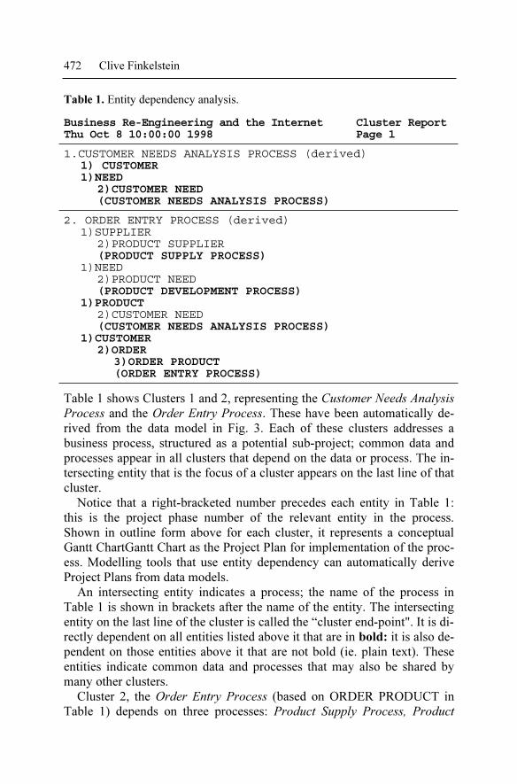
Table 1. Entity dependency analysis.
Business Re-Engineering and the Internet Cluster Report Thu Oct 8 10:00:00 1998 Page 1
1.CUSTOMER NEEDS ANALYSIS PROCESS (derived) 1) CUSTOMER 1)NEED 2)CUSTOMER NEED (CUSTOMER NEEDS ANALYSIS PROCESS)
2. ORDER ENTRY PROCESS (derived) 1)SUPPLIER 2)PRODUCT SUPPLIER
(PRODUCT SUPPLY PROCESS) 1)NEED 2)PRODUCT NEED
(PRODUCT DEVELOPMENT PROCESS) 1)PRODUCT 2)CUSTOMER NEED
(CUSTOMER NEEDS ANALYSIS PROCESS) 1)CUSTOMER 2)ORDER 3)ORDER PRODUCT (ORDER ENTRY PROCESS)
Table 1 shows Clusters 1 and 2, representing the Customer Needs Analysis
Process and the Order Entry Process. These have been automatically de-
rived from the data model in Fig. 3. Each of these clusters addresses a
business process, structured as a potential sub-project; common data and
processes appear in all clusters that depend on the data or process. The in-
tersecting entity that is the focus of a cluster appears on the last line of that
cluster.
Notice that a right-bracketed number precedes each entity in Table 1:
this is the project phase number of the relevant entity in the process.
Shown in outline form above for each cluster, it represents a conceptual
Gantt ChartGantt Chart as the Project Plan for implementation of the proc-
ess. Modelling tools that use entity dependency can automatically derive
Project Plans from data models.
An intersecting entity indicates a process; the name of the process in
Table 1 is shown in brackets after the name of the entity. The intersecting
entity on the last line of the cluster is called the “cluster end-point". It is di-
rectly dependent on all entities listed above it that are in bold: it is also de-
pendent on those entities above it that are not bold (ie. plain text). These
entities indicate common data and processes that may also be shared by
many other clusters.
Cluster 2, the Order Entry Process (based on ORDER PRODUCT in
Table 1) depends on three processes: Product Supply Process, Product

Information Engineering Methodology 473
Development Process and Customer Needs Analysis Process. We can see
that these are all prerequisite processes as their end-point entities are
shown in plain text. Analysis of the data model has determined that they
must all be carried out prior to the Order Entry Process. Furthermore, we
see that the Customer Needs Analysis Process (Cluster 1, based on
CUSTOMER NEED) has only bold entities within it, indicating that it is
not dependent on any other processes and therefore is an independent, pre-
requisite process.
Table 2 next shows that the first two of these processes are fully inter-
dependent: a product supplier cannot be selected without knowing the
needs addressed by the product (as each supplier names its products differ-
ently to other suppliers).
Table 2. Further entity dependency analysis.
Business Re-Engineering and the Internet Cluster Report
Thu Oct 8 10:00:00 1998 Page 1
3. PRODUCT DEVELOPMENT PROCESS (derived) 1)SUPPLIER 2)PRODUCT SUPPLIER (PRODUCT SUPPLY PROCESS) 1)PRODUCT 1)NEED 2)PRODUCT NEED (PRODUCT DEVELOPMENT PROCESS)
4. PRODUCT SUPPLY PROCESS (derived)
1)NEED
2)PRODUCT NEED
(PRODUCT DEVELOPMENT PROCESS)
1)PRODUCT
1)SUPPLIER
2)PRODUCT SUPPLIER
(PRODUCT SUPPLY PROCESS)
5.2 Automatic Data Map Generation
A cluster in outline form can be used to display a data map automatically.
For example, vertically aligning each entity by phase, from left to right,
shows the data map in Pert Chart format as illustrated in Fig. 4. Or instead
the data map can be rotated 90 degrees clockwise so that the entities are
horizontally displayed by phase, from top to bottom, in an Organization
Chart format. An entity name is displayed in an entity box; the attribute
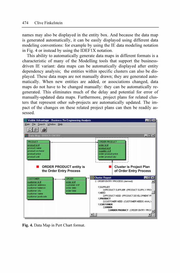
474 Clive Finkelstein
names may also be displayed in the entity box. And because the data map
is generated automatically, it can be easily displayed using different data
modeling conventions: for example by using the IE data modeling notation
in Fig. 4 or instead by using the IDEF1X notation.
This ability to automatically generate data maps in different formats is a
characteristic of many of the Modelling tools that support the business-
driven IE variant: data maps can be automatically displayed after entity
dependency analysis; the entities within specific clusters can also be dis-
played. These data maps are not manually drawn; they are generated auto-
matically. When new entities are added, or associations changed, data
maps do not have to be changed manually: they can be automatically re-
generated. This eliminates much of the delay and potential for error of
manually-updated data maps. Furthermore, project plans for related clus-
ters that represent other sub-projects are automatically updated. The im-
pact of the changes on these related project plans can then be readily as-
sessed.
Fig. 4. Data Map in Pert Chart format.

Information Engineering Methodology 475
5.3 Building Business Objects from Data Models
Similarly, process maps can be generated from data models. For example,
data maintenance and data access processes (Create, Read, Update, Delete)
can be automatically generated from entities in data models. These proc-
esses operate against the relevant entities as reusable object-oriented meth-
ods. They can be used to build reusable business processes that are docu-
mented as object-oriented process maps for business objects such as
Customer or Product.
For example, the Customer business object represents all data relating to
a Customer. It includes methods to Create a Customer, Read a Customer,
Update a Customer and Delete a Customer. It also includes standard Cus-
tomer screen formats and standard report formats for different security lev-
els. Thus any changes made to the Customer object are automatically re-
flected in all processes that use the Customer business object; they
automatically apply those Customer changes. Similarly methods derived
from Product, with Product screen and report formats, exist for the Product
object. Any Product changes can be made to this Product object, so auto-
matically changing all processes that refer to Products.
5.4 Project Critical Path Maps
We saw in Fig. 3 that a PRODUCT must have at least one SUPPLIER.
Table 1 thus includes the Product Supply Process to ensure that we are
aware of alternative suppliers for each product. But where did the Product
Development Process and Customer Needs Analysis Process come from?
The data map in Fig. 3 shows the business rule that each PRODUCT
must address at least one NEED relating to our core business. Similarly the
data map follows the Marketing rule that each CUSTOMER must have at
least one core business NEED. The Product Supply Process, Product De-
velopment Process and Customer Needs Analysis Process have therefore
all been included as prerequisite processes in Table 1.
The sequence for execution of these processes is shown in Fig. 5. This
shows each cluster as a named box, for the process represented by that
cluster. Each of these process boxes is therefore a sub-project for imple-
mentation. This diagram is called a Project Critical Path Map as it sug-
gests the development sequence for each sub-project.

476 Clive Finkelstein
Fig. 5. A Project Critical Path Map.
We can now see some of the power of entity dependency analysis: it auto-
matically applies business rules across the entire enterprise. As business
rules are defined in the data model, the case tool becomes a business ex-
pert: aware of all relevant business facts. It determines if other business ar-
eas should be notified of relevant business rules, data and processes. It de-
rives a Project Critical Path Map for project management of each sub-
project process that is needed to implement those processes as potential
computer systems.
So why have these prerequisite processes been included in the cluster in
Table 1 for the Order Entry Process, and in the Project Critical Path Map
in Fig. 5? What do these processes suggest? Do they help us to identify re-
engineering opportunities? Entity dependency uses Reengineering Oppor-
tunity Analysis to provide direct assistance for Business Re-Engineering.
5.5 Reengineering Opportunity Analysis
Fig. 5 shows that the prerequisite processes for Order Processing are cross-
functional; these separate processes can be integrated. Consider the follow-
ing scenario for Order Processing - before Business Re-Engineering:
Customer: “Customer 165 here. I would like to order 36 units of
Product X.”
Order Clerk: “Yes, certainly. … Oh, I see we are out of Product X at the
moment. I’ll check with the Warehouse. I will call you
back within the hour to let you know when we can expect
more of Product X into stock.”
Customer: “No don’t bother. I need to know now. Please cancel the
order.”

Information Engineering Methodology 477
Clearly, this example shows that the Order Clerk has no access to the In-
ventory Control System in the Warehouse. There is no way to determine
when outstanding purchase orders for out-of-stock products will be deliv-
ered. It requires a phone call to the Warehouse staff to get that information.
A call-back in an hour is no longer responsive for today’s customers. The
sale was therefore lost. Now consider the same scenario - after Business
Re-Engineering.
Customer: “Customer 165 here. I would like to order 36 units of
Product X.”
Order Clerk: “Yes, certainly. … Oh, I see we are out of Product X at the
moment. One moment while I check with our suppliers. …
Yes, we can deliver 36 units of Product X to you on
Wednesday.”
What has happened in this scenario? Product X was out of stock so the
Product Supply Process then automatically displayed all suppliers of
Product X. The Purchasing function had been re-engineered so the Order
Clerk can now link directly into each supplier’s inventory system to check
the availability and cost of Product X for each alternative source of supply.
For the selected supplier, the Clerk placed a purchase order for immediate
shipment and so could confirm the Wednesday delivery date with the cus-
tomer.
But there are problems with this approach, due to incompatibilities be-
tween the supplier’s Inventory Control System and the Order Entry Sys-
tem. There may be incompatibilities between the Operating Systems, Data
Base Management Systems, LANs, WANs and EDI data formats used by
both organizations. We will discuss these problems and their resolution,
shortly.
The re-engineered Product Supply Process discussed above seems revo-
lutionary, but other industries that also take orders online consider this in-
ter-enterprise approach to Order Entry the normal mode of operation. For
example, consider the Travel Industry. We phone a travel agent to book a
flight to Los Angeles (say) because we have business there. We need to ar-
rive on Wednesday evening for business on Thursday and Friday. But we
also decide to take the family and we plan to stay for the weekend, return-
ing Sunday evening. The travel agent uses an Airline Reservation terminal
to book seats on suitable flights. These are ordered from an inventory of
available seats offered by relevant suppliers: the Airlines. Let us now re-
turn to the customer on the phone - still talking to the Order Clerk, who
says.
478 Clive Finkelstein
Order Clerk: “By the way, do you know about Product Y. It allows you
to use Product X in half the time. I can send you 36 units
of Y as well for only 20%. Also users of Product X enjoy
Product Z. Have you used this. It has the characteristics of
… … and costs only … … Can I include 36 units of Prod-
uct Z as well in our Wednesday delivery?”
Customer: “Yes and thanks for those suggestions. I confirm that my
order is now for 36 units each of Products X, Y and Z - all
to be delivered on Wednesday.”
The Product Development Process displayed related products that met the
same needs as Product X. This suggested that Product Y may be of inter-
est. An order for Y, based on the current order for X, was automatically
prepared and priced … and Y was in stock. This extension to the order
only needed the customer’s approval for its inclusion in the delivery. Once
again, this is commonplace in the Travel Industry. The travel agent knows
the customer will be in Los Angeles over several nights and so asks
whether any hotel accommodation is needed. If so, a booking is made at a
suitable hotel using another supplier’s system: Hotel Reservations.
The Customer Needs Analysis Process then indicated that customers in
the same market as Customer 165 who also used Products X and Y, had
other needs that were addressed by Product Z, A further extension to in-
clude Z in the order was automatically prepared and priced. Z was also in
stock and was able to be included in the delivery, if agreed. This is analo-
gous to the Travel Agent asking if a rental car and tour bookings are also
needed: quite likely if a family is in Los Angeles for a weekend, and thus
near the theme parks and tourist resorts.
Instead of waiting for stock availability from the Warehouse in the first
scenario based on separate, non-integrated processes for each function, the
re-engineered scenario let the Clerk place a purchase order directly with a
selected supplier so that the customer’s order could be satisfied. And the
Product Development and Customer Needs Analysis processes then sug-
gested cross-selling opportunities based first on related products, and then
on related needs in the customer’s market.
Cross-functional processes identified with reengineering opportunity
analysis can suggest reorganization opportunities. For example, interde-
pendent processes may all be brought together in a new organization unit.
Or they may remain in their present organization structure, but be inte-
grated automatically by the computer only when needed - as in the re-
engineered scenario discussed above.
But what about the incompatibilities we discussed earlier with inter-
enterprise access to suppliers’ Inventory Systems. This is achieved by link-

Information Engineering Methodology 479
ing customers, suppliers and business partners together by Extranets, using
the Internet. This use of Internet technologies offers us dramatic new ways
to deploy applications and address otherwise insurmountable incompati-
bilities.
6 Deployment of Information Engineering Applications
Databases and information systems are today implemented using many
technologies. These include Data Warehouses with Executive Information
Systems, Decision Support Systems, Online Analytical Processing and
Decision Early Warning. They also include Client/Server systems devel-
oped using object-oriented languages. These are implemented today via
Intranets or Extranets, or are deployed directly to the Internet, Reviewing
the status of Internet and Intranet technologies today we find that:
• Web browsers are available for all platforms and operating systems,
based on an open architecture interface using HyperText Markup Lan-
guage (HTML). A key factor influencing future computing technologies
will be this open architecture environment.
• The Web browser market is largely shared between Microsoft and Net-
scape. But the strategy adopted by Microsoft has seen it rapidly gain
market share at the expense of Netscape, it is using its desktop owner-
ship to embed its browser technology (Internet Explorer) as an integral
and free component of Windows NT and the successors to Windows 95.
• The Internet is based on TCP/IP communications protocol and Domain
Naming System (DNS). Microsoft, Novell and other network vendors
recognize that TCP/IP and DNS are the network standards for the Inter-
net and Intranets. This open architecture network environment benefits
all end-users.
• The battle to become THE Internet language - between Java (from Sun)
and ActiveX (from Microsoft) will likely be won by neither. Browsers
support both languages and automatically download code as needed
from Web servers in a relevant language (as “applets”) for execution.
Instead, the winners of this battle will again be the end-users, who will
benefit from the open architecture execution environment.
• Data Base Management System (DBMS) vendors (those that plan to
survive) support dynamic generation of HTML for browsers, with trans-
parent access to the Internet and Intranets by applications using these
tools. They accept HTML input direct from Web forms, process the
relevant queries and generate dynamic HTML Web pages to present the

480 Clive Finkelstein
requested output, DBMS products with this capability include: Micro-
soft SQL Server, IBM DB2, Oracle, Sybase, CA-OpenIngres and In-
formix. Extensible Markup Language (XML) promises even more pow-
erful dynamic capabilities.
• Client/Server vendors (again those that plan to survive) also provide dy-
namic generation of HTML for browsers that are used as clients, with
transparent access to the Internet and Intranets for applications built
with those tools. Client code - written in either ActiveX or Java - is
downloaded as needed for execution and for generation of dynamic
HTML or XML output to display transaction results. Products include:
Microsoft Visual Basic, Visual J++, Access; Powersoft Optima++ and
Powerbuilder; Centura and SQLWindows; Borland Latte, Delphi &
C++.
• DataWarehouse and Data Mining products provide a similar capability:
accepting HTML input and generating HTML output if they are to be
used effectively via the Intranet and Internet. Screen Scraper tools with
GUI interfaces for Legacy Systems have also become internet, aware:
accepting 3270 data streams and dynamically translating them to (or
from) HTML to display on the screen. Thus they provide a transparent
HTML interface for easy migration of 3270 Legacy Systems to the
Internet and Intranets.
6.1 Internet and Intranet Deployment
The Internet has emerged since 1994 as a movement that will see all busi-
nesses inter-connected in the near future, with electronic commerce as the
norm. It indicates that most DBMS and Client/Server tools will interface
directly and transparently with the Internet and Intranet, Web browsers,
Java, HTML, XML, the Internet and Intranet all provide an open-
architecture interface for most operating system platforms. Previous in-
compatibilities between operating systems, DBMS products, Client/Server
products, LANs, WANs and EDI disappear - replaced by an open architec-
ture environment based on HTML, XML and Java.
6.2 Client/Server Systems
The client software for Client/Server systems becomes the web browser,
operating as a “fat” client by automatically downloading Java or ActiveX
code when needed. Client/Server tools typically offer two options, each

Information Engineering Methodology 481
able to be executed by any terminal which can run browsers or HTML-
aware code:
1. Transaction processing using client input via web forms, with dynami-
cally-generated HTML or XML web pages presenting output results in a
standard web browser format, OR
2. Transaction processing using client input via Client/Server screens, with
designed application-specific output screens built by client/server de-
velopment tools. This client environment recognizes HTML and XML,
dynamically translating and presenting that output using the designed
application-specific screens.
6.3 Data Warehouses
Client/Server development tools provide transparent access to data base
servers using HTML-access requests, whether accessing operational data
or DataWarehouses. In turn data base servers process these requests -
transparently using object-oriented logic developed with O-O languages
such as Java, or with ActiveX, to access new or legacy data bases as rele-
vant. These may be on separate servers, or instead may be on mainframes
executing legacy systems.
Web servers then operate as application servers, executing Java,
ActiveX or conventional code as part of the middle-tier of three-tier Cli-
ent/Server logic distribution for operational databases, with data base serv-
ers also executing Java, ActiveX or conventional code as the third logic
tier. Data Warehouses then take periodical extracts from operational data-
bases for multidimensional, time-dependent analysis using EIS, DSS,
OLAP and DEW software products.
7 Conclusion: What does the Future hold?
Managers of organizations in all industries and environments whether Pub-
lic Sector, Private Sector or Defense now recognize that the design and de-
velopment of successful information systems depends on business knowl-
edge as well as expertise in Information Technology. Business-driven
Information Engineering provides a very productive design partnership be-
tween business experts and IT experts. Together they are able to utilize
their respective knowledge to design databases and systems that are more
flexible and so are able to accommodate business change more readily.
482 Clive Finkelstein
This rapid change capability will be essential for survival and prosperity in
the competitive years ahead.
Development is also becoming easier, many of the incompatibilities we
previously had to deal with will soon be a thing of the past. Open architec-
ture development using the technologies of the Internet enables deploy-
ment on any PC with any hardware, operating system, DBMS, network,
client/server tool or Data Warehouse. This will be the direction that the IT
industry will take for the foreseeable future.
The open-architecture environment enjoyed by the audio industry –
where any CD or tape will run on any player, which can be connected to
any amplifier and speakers - has long been the holy grail of the IT indus-
try. Once the industry has made the transition over the next few years to
the open-architecture environment brought about by Internet and Intranet
technologies, we will be close to achieving that holy grail!
References
[Cod70] Codd, E., A Relational Model for Large Shared Data Banks, CACM 13
(6), 197, 377-87
[Cod79] Codd, E., Extending the Database Relational Model to Capture More
Meaning, ACM Trans. on Database Systems 4 (4), 1997, 397-434
[Dat82] Date, C., Introduction to Data Base, Volumes 1 and 2, Addison, Wesley,
Reading, 1982
[DeM82] De Marco, T., Software Systems Development, Yourdon Press, New
York, 1982
[Dru74] Drucker, P., Management: Tasks, Responsibilities, Practice, Harper &
Row, New York, 1974
[Fin81] Finkelstein, C., Information Engineering, six InDepth articles in: Com-
puterworld, Framingham, 1981
[Fin89] Finkelstein, C., An Introduction to Information Engineering, Addi-
son,Wesley, Sydney, 1989
[Fin92] Finkelstein, C., Information Engineering, Strategic Systems Development,
Addison,Wesley, Sydney, 1992
[FM81] Finkelstein, C., Martin, J., Information Engineering, Volumes 1 and 2,
Savant Institute, Carnforth, Lancs, 1981
[Jac75] Jackson, M., Principles of Program Design, Academic Press, New York,
1975
[Mar87] Martin, J., Information Engineering, Volumes 1, 2 and 3, Prentice, Hall,
Englewood Cliffs, 1987
[McC93] McClure, S., Information Engineering for Client/Server Architectures,
Data Base Newsletter, Boston, 1993
[Orr77] Orr, K., Structured Systems Development, Yourdon Press, New York,
1977

Information Engineering Methodology 483
[YC78] Yourdon, E., Constantine, L., Structured Design, Fundamentals of a Dis-
cipline of Computer Program Systems Design, Prentice-Hall, Englewood
Cliffs, 1978