information theory and channel coding
TRANSCRIPT
Information Theory and Channel Coding
Prof. Rodrigo C. de Lamare
CETUC, PUC-Rio, Brazil
XI. Polar codes
A. Introduction
B. Encoding and code structure
C. Decoding
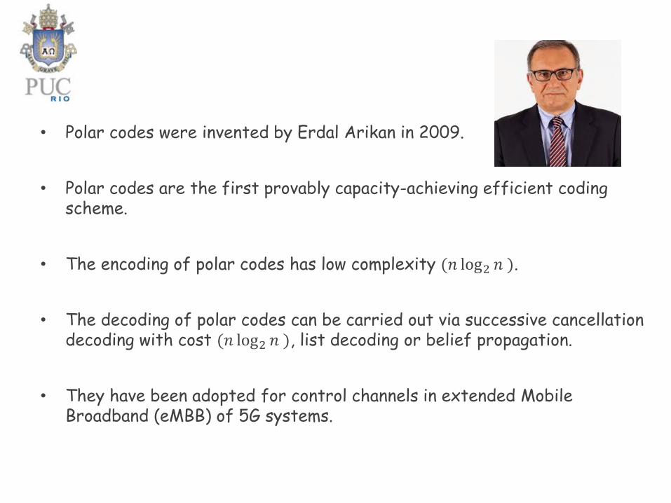
• Polar codes were invented by Erdal Arikan in 2009.
• Polar codes are the first provably capacity-achieving efficient coding scheme.
• The encoding of polar codes has low complexity (𝑛 log2 𝑛 ).
• The decoding of polar codes can be carried out via successive cancellationdecoding with cost (𝑛 log2 𝑛 ), list decoding or belief propagation.
• They have been adopted for control channels in extended Mobile Broadband (eMBB) of 5G systems.
A. Introduction
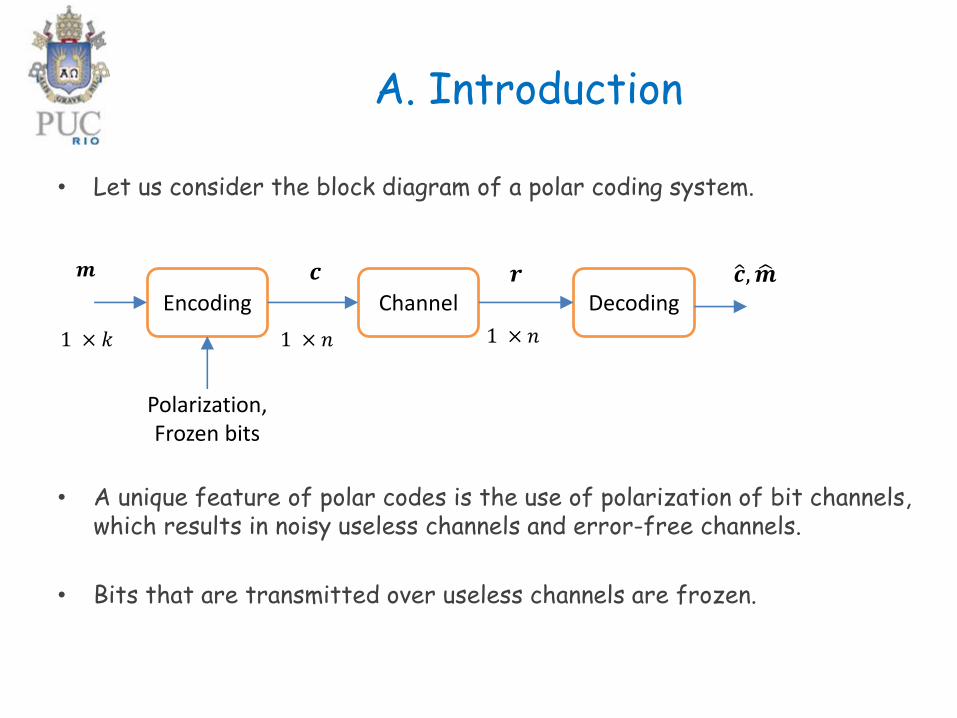
• Let us consider the block diagram of a polar coding system.
• A unique feature of polar codes is the use of polarization of bit channels, which results in noisy useless channels and error-free channels.
• Bits that are transmitted over useless channels are frozen.
Encoding Channel Decoding
𝒎 𝒄 𝒓 ො𝒄, ෝ𝒎
1 × 𝑘 1 × 𝑛 1 × 𝑛
Polarization,Frozen bits

• A building block of polar codes is the basic channel transformationillustrated by
where 𝑊 is a discrete memoryless channel (DMC).
• For an error-free/ perfect channel:o 𝑌 determines 𝑋o No need to encode data.
• For a useless channel:o 𝑌 is independent of 𝑋o No need to encode.
𝑊𝑈1
𝑈2
𝑊
𝑋1
𝑋2
𝑌1
𝑌2
• Concatenation of DMCs:
o Channels that are perfect or useless but nothing in between-> polarization
o In a polar coding system a given DMC 𝑊 is used 𝑛 times to transmit a codeword.
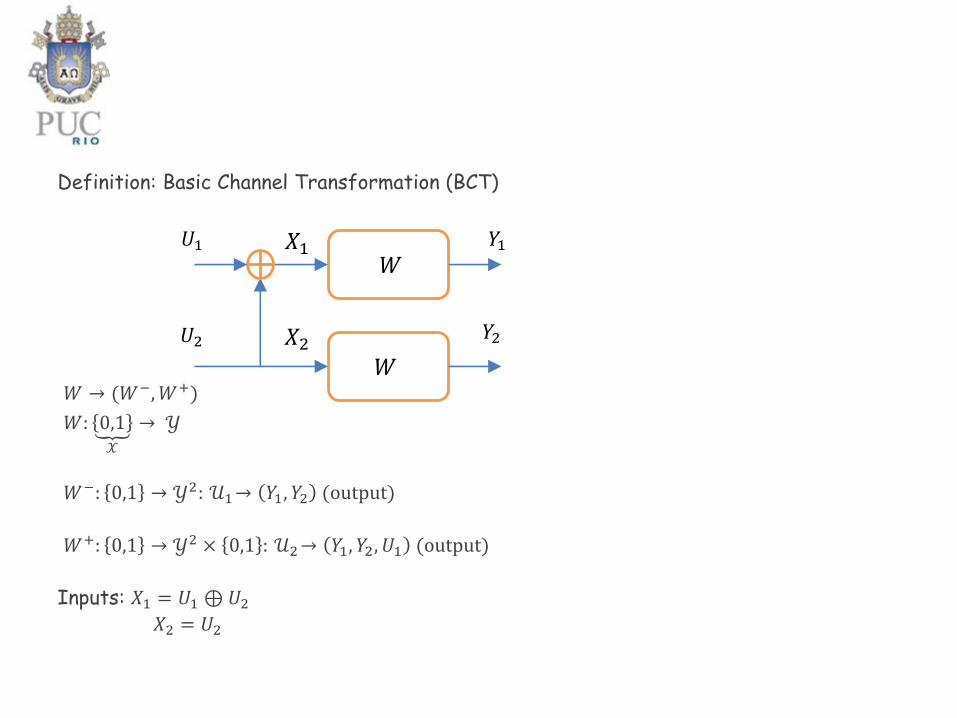
Definition: Basic Channel Transformation (BCT)
𝑊 → (𝑊−,𝑊+)
𝑊: ถ0,1𝒳
→ 𝒴
𝑊−: 0,1 → 𝒴2: 𝒰1→ 𝑌1, 𝑌2 (output)
𝑊+: 0,1 → 𝒴2 × 0,1 : 𝒰2→ 𝑌1, 𝑌2, 𝑈1 (output)
Inputs: 𝑋1 = 𝑈1 ⊕𝑈2𝑋2 = 𝑈2
𝑊𝑈1
𝑈2
𝑊
𝑋1
𝑋2
𝑌1
𝑌2
Example 1
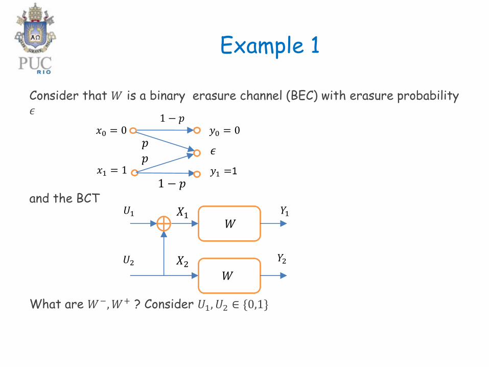
Consider that 𝑊 is a binary erasure channel (BEC) with erasure probability𝜖
and the BCT
What are 𝑊−,𝑊+ ? Consider 𝑈1, 𝑈2 ∈ {0,1}
𝑊𝑈1
𝑈2
𝑊
𝑋1
𝑋2
𝑌1
𝑌2
𝑥0 = 0
𝑥1 = 1
𝑦0 = 0
𝑦1 =1
𝜖
1 − 𝑝
1 − 𝑝
𝑝
𝑝
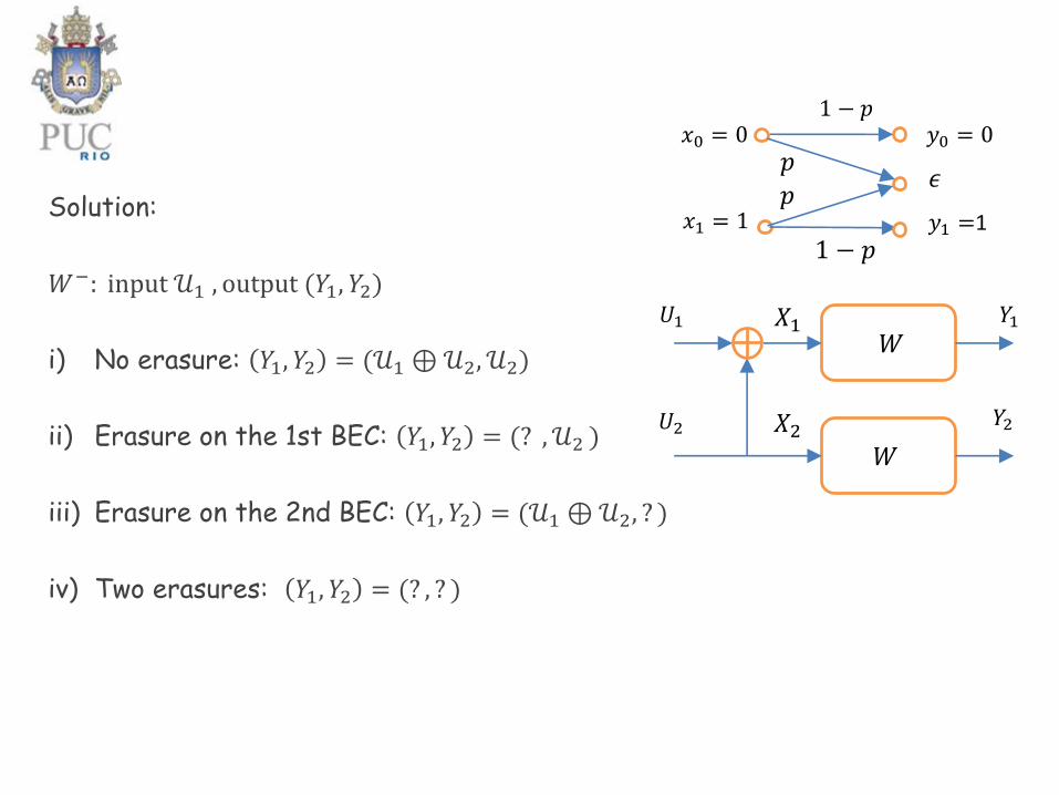
Solution:
𝑊−: input 𝒰1 , output (𝑌1, 𝑌2)
i) No erasure: 𝑌1, 𝑌2 = (𝒰1 ⊕𝒰2, 𝒰2)
ii) Erasure on the 1st BEC: 𝑌1, 𝑌2 = (? , 𝒰2 )
iii) Erasure on the 2nd BEC: 𝑌1, 𝑌2 = (𝒰1 ⊕𝒰2, ? )
iv) Two erasures: 𝑌1, 𝑌2 = (? , ? )
𝑊𝑈1
𝑈2
𝑊
𝑋1
𝑋2
𝑌1
𝑌2
𝑥0 = 0
𝑥1 = 1
𝑦0 = 0
𝑦1 =1
𝜖
1 − 𝑝
1 − 𝑝
𝑝
𝑝
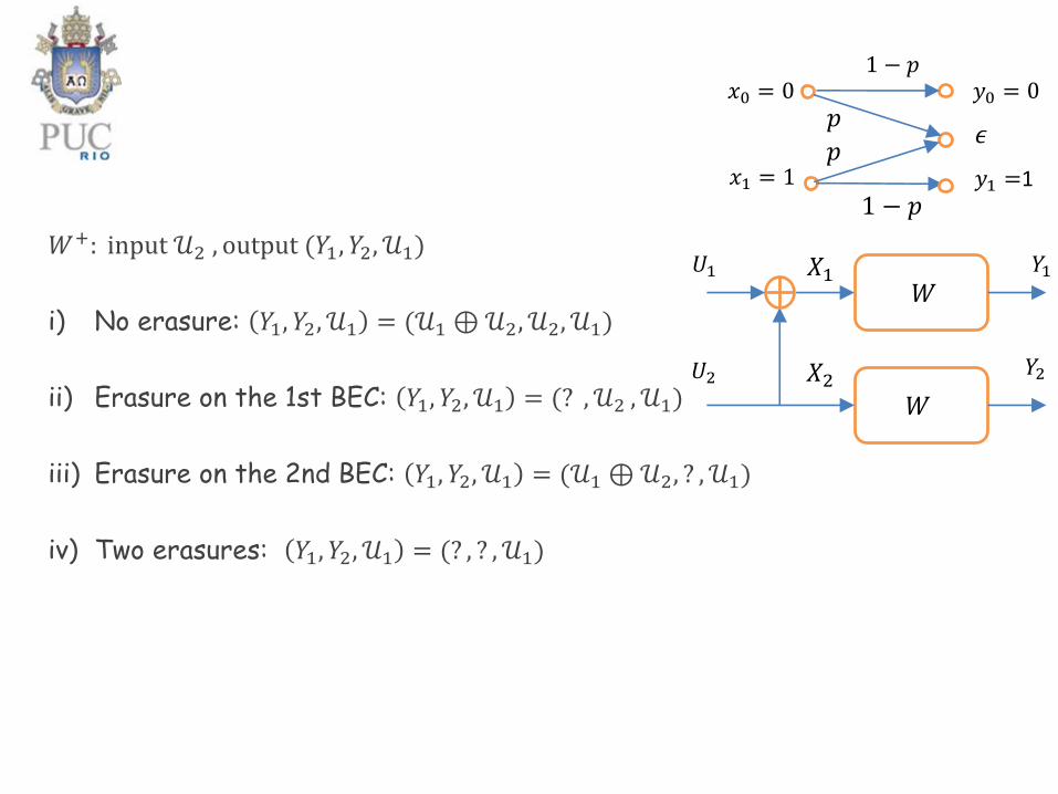
𝑊+: input 𝒰2 , output (𝑌1, 𝑌2, 𝒰1)
i) No erasure: 𝑌1, 𝑌2, 𝒰1 = (𝒰1 ⊕𝒰2, 𝒰2, 𝒰1)
ii) Erasure on the 1st BEC: 𝑌1, 𝑌2, 𝒰1 = (? , 𝒰2 , 𝒰1)
iii) Erasure on the 2nd BEC: 𝑌1, 𝑌2, 𝒰1 = (𝒰1 ⊕𝒰2, ? , 𝒰1)
iv) Two erasures: 𝑌1, 𝑌2, 𝒰1 = (? , ? , 𝒰1)
𝑊𝑈1
𝑈2
𝑊
𝑋1
𝑋2
𝑌1
𝑌2
𝑥0 = 0
𝑥1 = 1
𝑦0 = 0
𝑦1 =1
𝜖
1 − 𝑝
1 − 𝑝
𝑝
𝑝
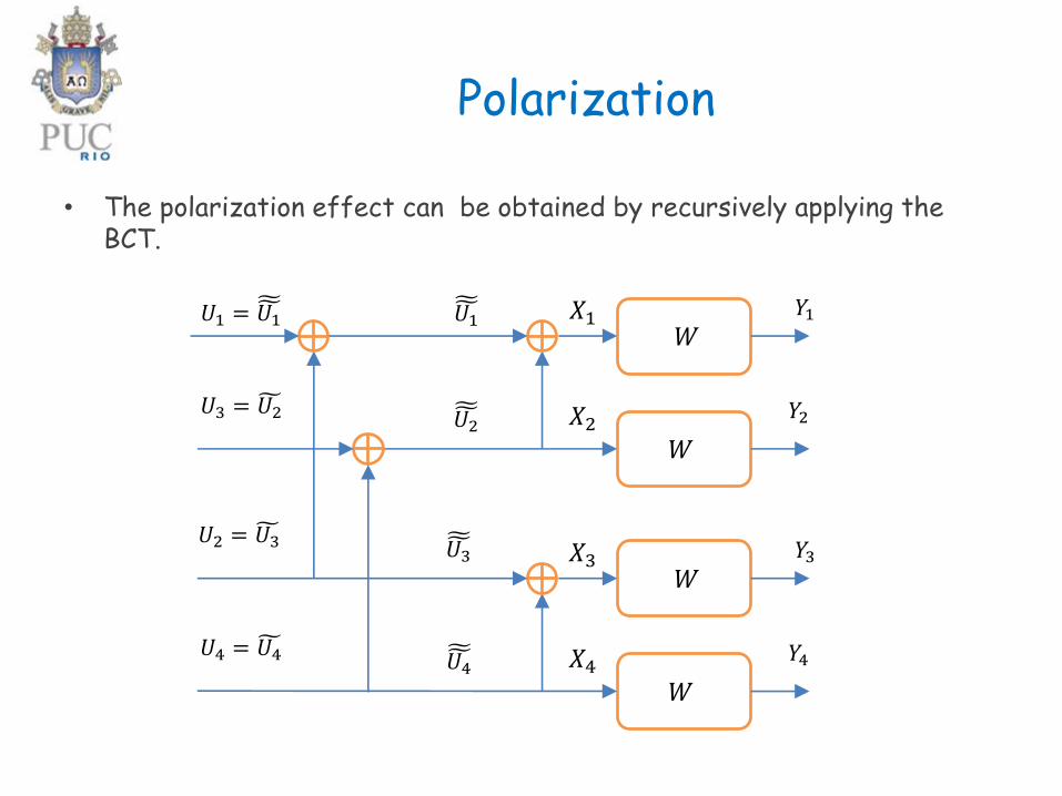
Polarization
• The polarization effect can be obtained by recursively applying theBCT.
𝑊
෪෪𝑈1
𝑊
𝑋1
𝑋2
𝑌1
𝑌2
𝑊
𝑊
𝑋3
𝑋4
𝑌3
𝑌4
෪෪𝑈2
𝑈1 =෪෪𝑈1
𝑈3 = ෪𝑈2
෪෪𝑈3
෪෪𝑈4
𝑈2 = ෪𝑈3
𝑈4 = ෪𝑈4

• 1st copy of 𝑊: input 𝑋1, output 𝑌1• 2nd copy of 𝑊: input 𝑋2, output 𝑌2
𝑊−: ෪෪𝑈1 → 𝑌1, 𝑌2 , where 𝑋1 =෪෪𝑈1 ⊕
෪෪𝑈2
𝑊+:෪෪𝑈2 → 𝑌1, 𝑌2,෪෪𝑈1 , where 𝑋2 =
෪෪𝑈2
• 3rd copy of 𝑊: input 𝑋3, output 𝑌3• 4th copy of 𝑊: input 𝑋4, output 𝑌4
𝑊−:෪෪𝑈1 → 𝑌1, 𝑌2 , where 𝑋1 =෪෪𝑈1 ⊕
෪෪𝑈2
𝑊+: ෪෪𝑈2 → 𝑌1, 𝑌2,෪෪𝑈1 , where 𝑋2 =
෪෪𝑈2
𝑊
෪෪𝑈1
𝑊
𝑋1
𝑋2
𝑌1
𝑌2
𝑊
𝑊
𝑋3
𝑋4
𝑌3
𝑌4
෪෪𝑈2
𝑈1 =෪෪𝑈1
𝑈3 = ෪𝑈2
෪෪𝑈3
෪෪𝑈4
𝑈2 = ෪𝑈3
𝑈4 = ෪𝑈4

• Application of BCT to 𝑊−:
1st copy of 𝑊: input ෪෪𝑈1, output (Y1, 𝑌2)
2nd copy of 𝑊: input ෪෪𝑈3, output (𝑌3, 𝑌4)
𝑊−−: ෪෪𝑈1 → 𝑌1, 𝑌2, 𝑌3, 𝑌4 , where ෪෪𝑈1 = ෪𝑈1 ⊕ ෪𝑈3
𝑊−+: ෪෪𝑈2 → 𝑌1, 𝑌2, 𝑌3, 𝑌4, ෪𝑈1 , where෪෪𝑈3 = ෪𝑈3
• Application of BCT to 𝑊+:
1st copy of 𝑊: input ෪෪𝑈2, output (Y1, 𝑌2, 𝑈1)
2nd copy of 𝑊: input ෪෪𝑈4, output (𝑌3, 𝑌4,෪෪𝑈3)
𝑊+−: ෪෪𝑈2 → 𝑌1, 𝑌2, 𝑌3, 𝑌4,෪෪𝑈1,
෪෪𝑈3, , where ෪෪𝑈2 = ෪𝑈2 ⊕ ෪𝑈4
𝑊++: ෪෪𝑈2 → 𝑌1, 𝑌2, 𝑌3, 𝑌4,෪෪𝑈1,
෪෪𝑈3, 𝑈2 ǁ , where෪෪𝑈4 = ෪𝑈4
𝑊
෪෪𝑈1
𝑊
𝑋1
𝑋2
𝑌1
𝑌2
𝑊
𝑊
𝑋3
𝑋4
𝑌3
𝑌4
෪෪𝑈2
𝑈1 = ෪𝑈1
𝑈3 = ෪𝑈2
෪෪𝑈3
෪෪𝑈4
𝑈2 = ෪𝑈3
𝑈4 = ෪𝑈4
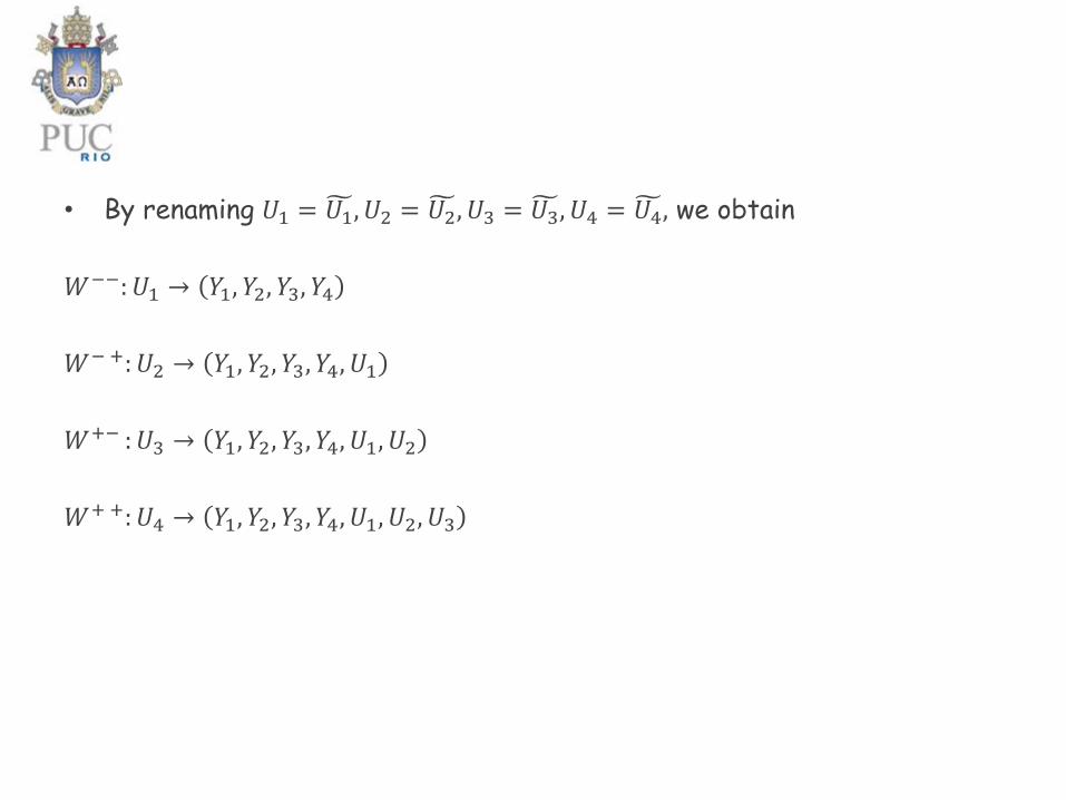
• By renaming 𝑈1 = ෪𝑈1, 𝑈2 = ෪𝑈2, 𝑈3 = ෪𝑈3, 𝑈4 = ෪𝑈4, we obtain
𝑊−−: 𝑈1 → 𝑌1, 𝑌2, 𝑌3, 𝑌4
𝑊− +: 𝑈2 → 𝑌1, 𝑌2, 𝑌3, 𝑌4, 𝑈1
𝑊+− : 𝑈3 → 𝑌1, 𝑌2, 𝑌3, 𝑌4, 𝑈1, 𝑈2
𝑊+ +: 𝑈4 → 𝑌1, 𝑌2, 𝑌3, 𝑌4, 𝑈1, 𝑈2, 𝑈3
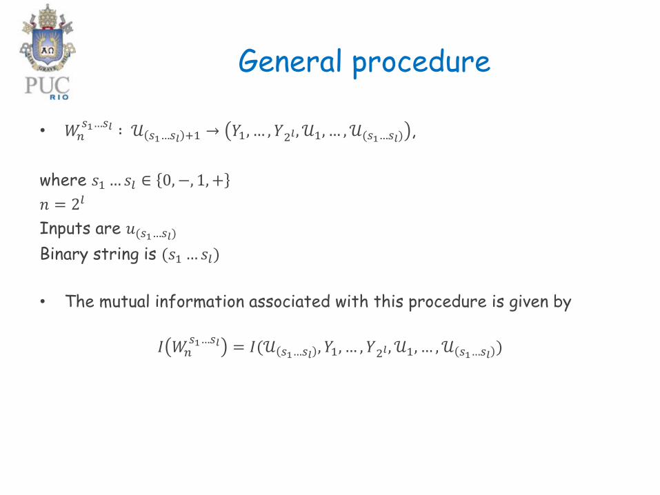
General procedure
• 𝑊𝑛𝑠1…𝑠𝑙 ∶ 𝒰 𝑠1…𝑠𝑙 +1 → 𝑌1, … , 𝑌2𝑙 , 𝒰1, … , 𝒰(𝑠1…𝑠𝑙) ,
where 𝑠1…𝑠𝑙 ∈ 0,−, 1, +
𝑛 = 2𝑙
Inputs are 𝑢(𝑠1…𝑠𝑙)
Binary string is (𝑠1…𝑠𝑙)
• The mutual information associated with this procedure is given by
𝐼 𝑊𝑛𝑠1…𝑠𝑙 = 𝐼(𝒰 𝑠1…𝑠𝑙 , 𝑌1, … , 𝑌2𝑙 , 𝒰1, … , 𝒰 𝑠1…𝑠𝑙 )
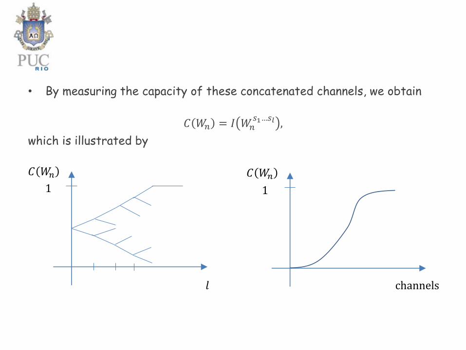
• By measuring the capacity of these concatenated channels, we obtain
𝐶 𝑊𝑛 = 𝐼 𝑊𝑛𝑠1…𝑠𝑙 ,
which is illustrated by
𝐶 𝑊𝑛
𝑙
𝐶 𝑊𝑛
1 1
channels
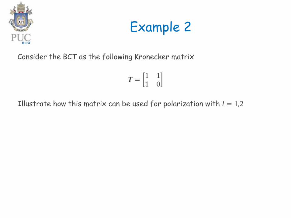
Example 2
Consider the BCT as the following Kronecker matrix
𝑻 =1 11 0
Illustrate how this matrix can be used for polarization with 𝑙 = 1,2
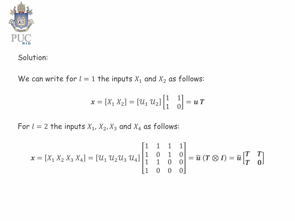
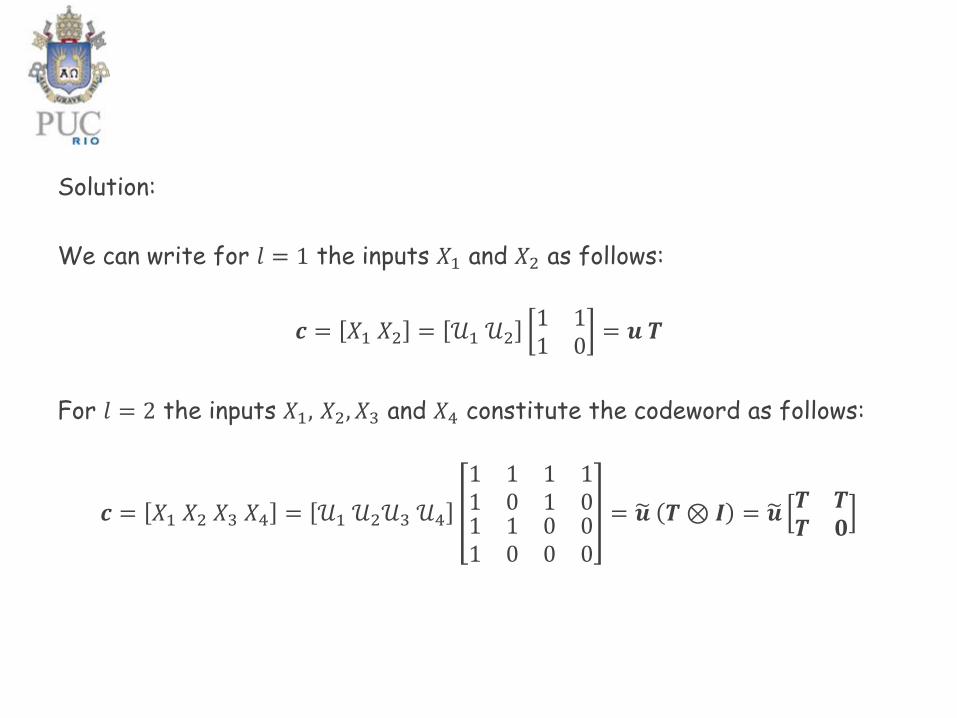
Solution:
We can write for 𝑙 = 1 the inputs 𝑋1 and 𝑋2 as follows:
𝒙 = 𝑋1 𝑋2 = 𝒰1 𝒰21 11 0
= 𝒖 𝑻
For 𝑙 = 2 the inputs 𝑋1, 𝑋2, 𝑋3 and 𝑋4 as follows:
𝒙 = 𝑋1 𝑋2 𝑋3 𝑋4 = 𝒰1 𝒰2𝒰3 𝒰4
1 11 0
1 11 0
1 11 0
0 00 0
= 𝒖 𝑻⊗ 𝑰 = 𝒖𝑻 𝑻𝑻 𝟎
B. Encoding
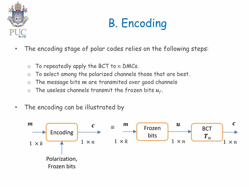
• The encoding stage of polar codes relies on the following steps:
o To repeatedly apply the BCT to 𝑛 DMCs.
o To select among the polarized channels those that are best.
o The message bits 𝒎 are transmited over good channels
o The useless channels transmit the frozen bits 𝒖𝑓.
• The encoding can be illustrated by
Encoding
𝒎 𝒄
1 × 𝑘 1 × 𝑛
Polarization,Frozen bits
Frozenbits
𝒎
1 × 𝑘 1 × 𝑛
𝒖BCT𝑻𝑛
𝒄
1 × 𝑛
≡
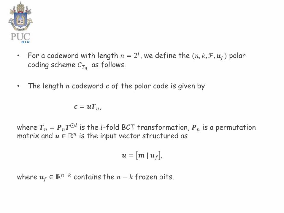
• For a codeword with length 𝑛 = 2𝑙, we define the (𝑛, 𝑘, ℱ, 𝒖𝑓) polar coding scheme 𝒞𝑇𝑛 as follows.
• The length 𝑛 codeword 𝒄 of the polar code is given by
𝒄 = 𝒖𝑻𝑛,
where 𝑻𝑛 = 𝑷𝑛𝑻⊙𝒍 is the 𝑙-fold BCT transformation, 𝑷𝑛 is a permutation
matrix and 𝒖 ∈ ℝ𝑛 is the input vector structured as
𝒖 = 𝒎 | 𝒖𝑓 ,
where 𝒖𝑓 ∈ ℝ𝑛−𝑘 contains the 𝑛 − 𝑘 frozen bits.
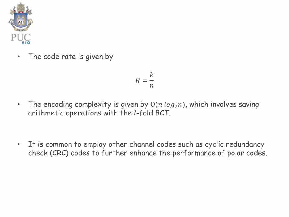
• The code rate is given by
𝑅 =𝑘
𝑛
• The encoding complexity is given by O(𝑛 𝑙𝑜𝑔2𝑛), which involves savingarithmetic operations with the 𝑙-fold BCT.
• It is common to employ other channel codes such as cyclic redundancycheck (CRC) codes to further enhance the performance of polar codes.
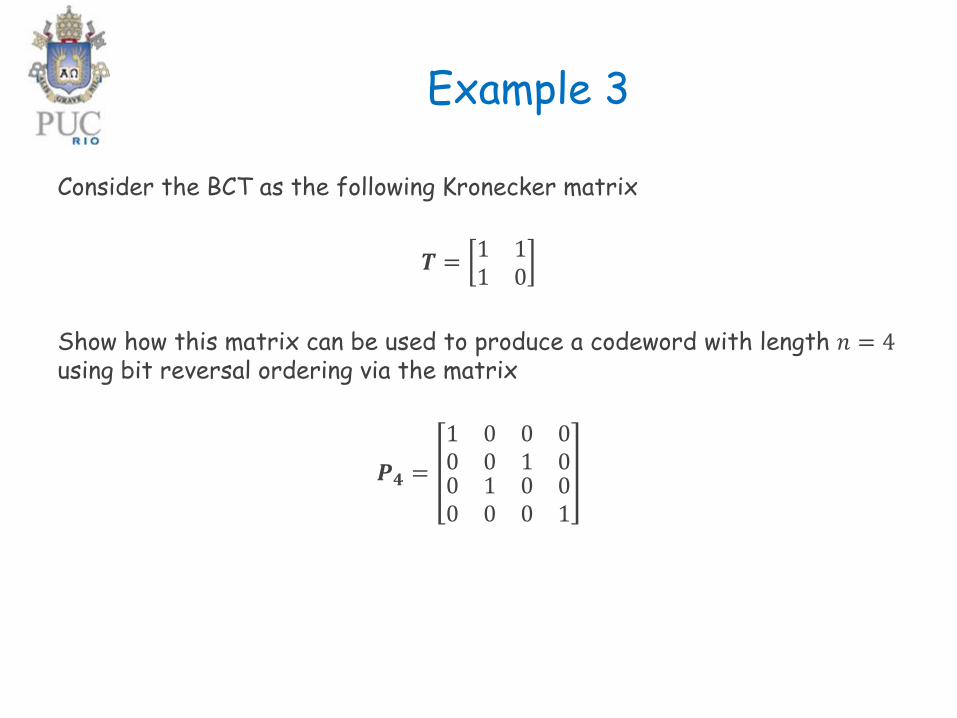
Example 3
Consider the BCT as the following Kronecker matrix
𝑻 =1 11 0
Show how this matrix can be used to produce a codeword with length 𝑛 = 4using bit reversal ordering via the matrix
𝑷𝟒 =
1 00 0
0 01 0
0 10 0
0 00 1
Solution:
We can write for 𝑙 = 1 the inputs 𝑋1 and 𝑋2 as follows:
𝒄 = 𝑋1 𝑋2 = 𝒰1 𝒰21 11 0
= 𝒖 𝑻
For 𝑙 = 2 the inputs 𝑋1, 𝑋2, 𝑋3 and 𝑋4 constitute the codeword as follows:
𝒄 = 𝑋1 𝑋2 𝑋3 𝑋4 = 𝒰1 𝒰2𝒰3 𝒰4
1 11 0
1 11 0
1 11 0
0 00 0
= 𝒖 𝑻⊗ 𝑰 = 𝒖𝑻 𝑻𝑻 𝟎

Using the bit-reversal matrix, we can write
𝒖 = 𝒖𝑷4and
𝒄 = 𝒖 𝑻⊗ 𝑰 = 𝒖𝑷4𝑻 𝑻𝑻 𝟎
= 𝒖𝑷4𝑻⊙𝟐 = 𝒖𝑻4
= 𝒰1 𝒰2𝒰3 𝒰4
1 11 1
1 10 0
1 01 0
1 00 0
Therefore, in general we have
𝑻𝑛 = 𝑷𝑛𝑻⊙𝒍
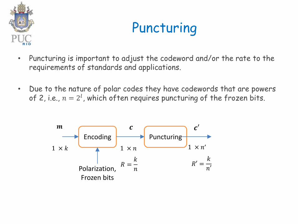
Puncturing
• Puncturing is important to adjust the codeword and/or the rate to therequirements of standards and applications.
• Due to the nature of polar codes they have codewords that are powersof 2, i.e., 𝑛 = 2𝑙, which often requires puncturing of the frozen bits.
Encoding Puncturing
𝒎 𝒄
1 × 𝑘 1 × 𝑛 1 × 𝑛’
Polarization,Frozen bits
𝒄′
𝑅 =𝑘
𝑛𝑅′ =
𝑘
𝑛′
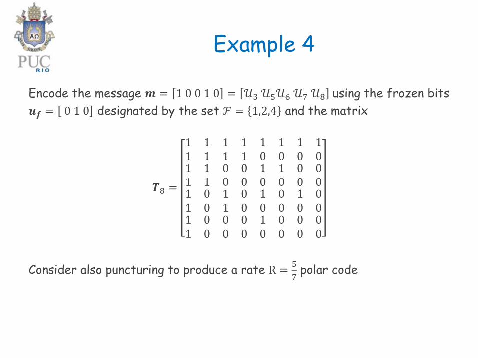
Example 4
Encode the message 𝒎 = 1 0 0 1 0 = 𝒰3 𝒰5𝒰6 𝒰7 𝒰8 using the frozen bits
𝒖𝒇 = 0 1 0 designated by the set ℱ = 1,2,4 and the matrix
𝑻8 =
1 11 1
1 11 1
1 11 1
0 00 0
1 10 0
1 10 0
1 10 0
0 00 0
1 01 0
1 01 0
1 01 0
0 00 0
1 00 0
1 00 0
1 00 0
0 00 0
Consider also puncturing to produce a rate R =5
7polar code
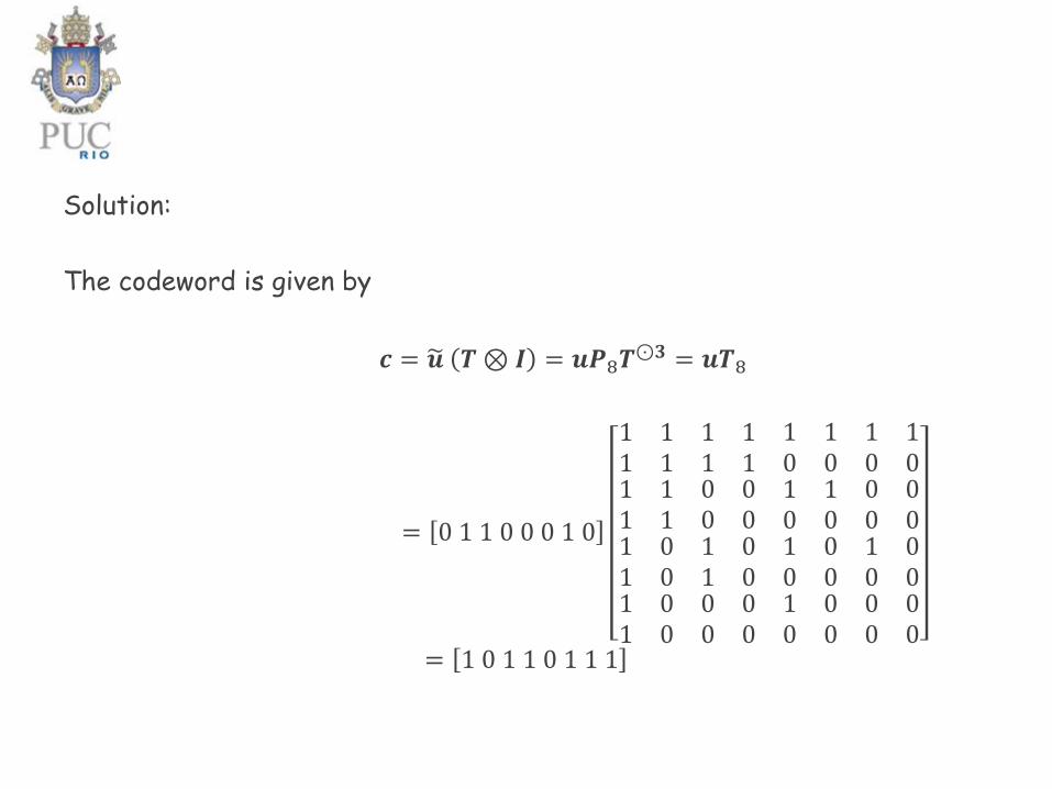
Solution:
The codeword is given by
𝒄 = 𝒖 𝑻⊗ 𝑰 = 𝒖𝑷8𝑻⊙𝟑 = 𝒖𝑻8
= 0 1 1 0 0 0 1 0
1 11 1
1 11 1
1 11 1
0 00 0
1 10 0
1 10 0
1 10 0
0 00 0
1 01 0
1 01 0
1 01 0
0 00 0
1 00 0
1 00 0
1 00 0
0 00 0
= 1 0 1 1 0 1 1 1

In order to puncture this code to obtain a rate R =5
7polar code, we need
to discard 1 frozen bit, which would result in
𝒄 = 0 1 1 0 1 1 1
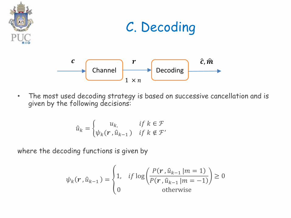
C. Decoding
• The most used decoding strategy is based on successive cancellation and isgiven by the following decisions:
ො𝑢𝑘 = ቊ𝑢𝑘, 𝑖𝑓 𝑘 ∈ ℱ
𝜓𝑘(𝒓 , ො𝑢𝑘−1 ) 𝑖𝑓 𝑘 ∉ ℱ,
where the decoding functions is given by
𝜓𝑘 𝒓 , ො𝑢𝑘−1 = ൞1, 𝑖𝑓 log
𝑃 𝒓 , ො𝑢𝑘−1 |𝑚 = 1
𝑃 𝒓 , ො𝑢𝑘−1 |𝑚 = −1≥ 0
0 otherwise
Channel Decoding
𝒄 𝒓 ො𝒄, ෝ𝒎
1 × 𝑛
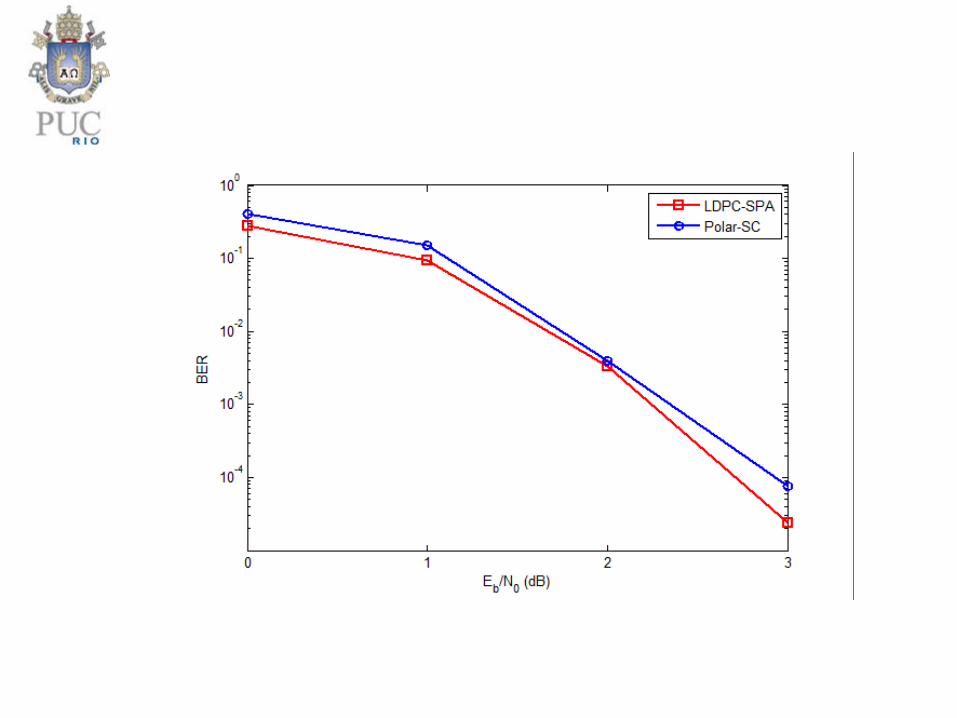
Example 5
Compare the performance of an LDPC code and a polar code with
puncturing, 𝑛 = 1920 and rate 𝑅 =1
4.